KR20170030431A - Aluminum differential housing with cast iron inserts - Google Patents
Aluminum differential housing with cast iron inserts Download PDFInfo
- Publication number
- KR20170030431A KR20170030431A KR1020160108957A KR20160108957A KR20170030431A KR 20170030431 A KR20170030431 A KR 20170030431A KR 1020160108957 A KR1020160108957 A KR 1020160108957A KR 20160108957 A KR20160108957 A KR 20160108957A KR 20170030431 A KR20170030431 A KR 20170030431A
- Authority
- KR
- South Korea
- Prior art keywords
- differential
- housing
- axis
- pair
- openings
- Prior art date
Links
Images


Classifications
-
- B—PERFORMING OPERATIONS; TRANSPORTING
- B60—VEHICLES IN GENERAL
- B60K—ARRANGEMENT OR MOUNTING OF PROPULSION UNITS OR OF TRANSMISSIONS IN VEHICLES; ARRANGEMENT OR MOUNTING OF PLURAL DIVERSE PRIME-MOVERS IN VEHICLES; AUXILIARY DRIVES FOR VEHICLES; INSTRUMENTATION OR DASHBOARDS FOR VEHICLES; ARRANGEMENTS IN CONNECTION WITH COOLING, AIR INTAKE, GAS EXHAUST OR FUEL SUPPLY OF PROPULSION UNITS IN VEHICLES
- B60K17/00—Arrangement or mounting of transmissions in vehicles
- B60K17/04—Arrangement or mounting of transmissions in vehicles characterised by arrangement, location, or kind of gearing
- B60K17/16—Arrangement or mounting of transmissions in vehicles characterised by arrangement, location, or kind of gearing of differential gearing
-
- F—MECHANICAL ENGINEERING; LIGHTING; HEATING; WEAPONS; BLASTING
- F16—ENGINEERING ELEMENTS AND UNITS; GENERAL MEASURES FOR PRODUCING AND MAINTAINING EFFECTIVE FUNCTIONING OF MACHINES OR INSTALLATIONS; THERMAL INSULATION IN GENERAL
- F16H—GEARING
- F16H57/00—General details of gearing
- F16H57/02—Gearboxes; Mounting gearing therein
- F16H57/037—Gearboxes for accommodating differential gearings
-
- F—MECHANICAL ENGINEERING; LIGHTING; HEATING; WEAPONS; BLASTING
- F16—ENGINEERING ELEMENTS AND UNITS; GENERAL MEASURES FOR PRODUCING AND MAINTAINING EFFECTIVE FUNCTIONING OF MACHINES OR INSTALLATIONS; THERMAL INSULATION IN GENERAL
- F16H—GEARING
- F16H48/00—Differential gearings
- F16H48/38—Constructional details
- F16H48/40—Constructional details characterised by features of the rotating cases
-
- B—PERFORMING OPERATIONS; TRANSPORTING
- B22—CASTING; POWDER METALLURGY
- B22D—CASTING OF METALS; CASTING OF OTHER SUBSTANCES BY THE SAME PROCESSES OR DEVICES
- B22D19/00—Casting in, on, or around objects which form part of the product
- B22D19/02—Casting in, on, or around objects which form part of the product for making reinforced articles
-
- F—MECHANICAL ENGINEERING; LIGHTING; HEATING; WEAPONS; BLASTING
- F16—ENGINEERING ELEMENTS AND UNITS; GENERAL MEASURES FOR PRODUCING AND MAINTAINING EFFECTIVE FUNCTIONING OF MACHINES OR INSTALLATIONS; THERMAL INSULATION IN GENERAL
- F16H—GEARING
- F16H48/00—Differential gearings
- F16H48/06—Differential gearings with gears having orbital motion
- F16H48/08—Differential gearings with gears having orbital motion comprising bevel gears
-
- F—MECHANICAL ENGINEERING; LIGHTING; HEATING; WEAPONS; BLASTING
- F16—ENGINEERING ELEMENTS AND UNITS; GENERAL MEASURES FOR PRODUCING AND MAINTAINING EFFECTIVE FUNCTIONING OF MACHINES OR INSTALLATIONS; THERMAL INSULATION IN GENERAL
- F16H—GEARING
- F16H57/00—General details of gearing
- F16H57/02—Gearboxes; Mounting gearing therein
- F16H57/032—Gearboxes; Mounting gearing therein characterised by the materials used
-
- F—MECHANICAL ENGINEERING; LIGHTING; HEATING; WEAPONS; BLASTING
- F16—ENGINEERING ELEMENTS AND UNITS; GENERAL MEASURES FOR PRODUCING AND MAINTAINING EFFECTIVE FUNCTIONING OF MACHINES OR INSTALLATIONS; THERMAL INSULATION IN GENERAL
- F16H—GEARING
- F16H57/00—General details of gearing
- F16H57/04—Features relating to lubrication or cooling or heating
- F16H57/042—Guidance of lubricant
- F16H57/043—Guidance of lubricant within rotary parts, e.g. axial channels or radial openings in shafts
-
- F—MECHANICAL ENGINEERING; LIGHTING; HEATING; WEAPONS; BLASTING
- F16—ENGINEERING ELEMENTS AND UNITS; GENERAL MEASURES FOR PRODUCING AND MAINTAINING EFFECTIVE FUNCTIONING OF MACHINES OR INSTALLATIONS; THERMAL INSULATION IN GENERAL
- F16H—GEARING
- F16H57/00—General details of gearing
- F16H57/04—Features relating to lubrication or cooling or heating
- F16H57/048—Type of gearings to be lubricated, cooled or heated
- F16H57/0482—Gearings with gears having orbital motion
- F16H57/0483—Axle or inter-axle differentials
-
- F—MECHANICAL ENGINEERING; LIGHTING; HEATING; WEAPONS; BLASTING
- F16—ENGINEERING ELEMENTS AND UNITS; GENERAL MEASURES FOR PRODUCING AND MAINTAINING EFFECTIVE FUNCTIONING OF MACHINES OR INSTALLATIONS; THERMAL INSULATION IN GENERAL
- F16H—GEARING
- F16H48/00—Differential gearings
- F16H48/06—Differential gearings with gears having orbital motion
- F16H48/08—Differential gearings with gears having orbital motion comprising bevel gears
- F16H2048/085—Differential gearings with gears having orbital motion comprising bevel gears characterised by shafts or gear carriers for orbital gears
-
- F—MECHANICAL ENGINEERING; LIGHTING; HEATING; WEAPONS; BLASTING
- F16—ENGINEERING ELEMENTS AND UNITS; GENERAL MEASURES FOR PRODUCING AND MAINTAINING EFFECTIVE FUNCTIONING OF MACHINES OR INSTALLATIONS; THERMAL INSULATION IN GENERAL
- F16H—GEARING
- F16H57/00—General details of gearing
- F16H57/02—Gearboxes; Mounting gearing therein
- F16H2057/02091—Measures for reducing weight of gearbox
Landscapes
- Engineering & Computer Science (AREA)
- General Engineering & Computer Science (AREA)
- Mechanical Engineering (AREA)
- Chemical & Material Sciences (AREA)
- Combustion & Propulsion (AREA)
- Transportation (AREA)
- Retarders (AREA)
Abstract
Description
본 발명은 자동차 파워트레인용 차동 하우징, 및 보다 구체적으로는 주철 인서트를 구비한 자동차 파워트레인용 경량 주조 알루미늄 차동 하우징에 관한 것이다.The present invention relates to a differential housing for automotive powertrain, and more particularly to a lightweight cast aluminum differential housing for automotive powertrain with cast iron inserts.
본원의 기재는 본 발명과 관련된 배경기술을 제공하는 것에 불과하며, 종래기술을 구성할 수 있거나 구성하지 않을 수 있다.The description herein is merely to provide background information related to the present invention, and may or may not constitute prior art.
종래의 파워트레인을 구비한 모든 자동차는 사실상 적어도 하나의 차동장치를 포함하는데, 이는 모두 구동 토크를 좌우 전륜(front wheel) 또는 후륜(rear wheel)으로 향하게 하며, 차량이 코너를 돌고 지나갈 때 후방 차축을 스크러빙(scrubbing)하거나 와인딩(winding)하는 것 없이 바퀴가 상이한 속도로 회전하게 한다. 차동장치는 하이포이드(hypoid) 및 링 기어 어셈블리를 통해 구동되는 케이지 또는 하우징을 포함하며, 관련 바퀴를 구동하는 좌우 차축에 연결된 2개의 기어와 상시 물림(constant mesh) 상태인 2개의 베벨 유동 기어(bevel idler gear)를 포함한다. 케이지 또는 하우징은 통상적으로 주철이며, 유동기어가 배치된 스터브 샤프트(stub shaft)를 지지하는 저널 베어링(journal bearings)을 포함한다. 관련 기어, 샤프트 및 베어링에 의해서 받는 힘(force)과 차동 장치에 가해지는 동력(power) 때문에, 하우징을 위해 주철을 선택하는 것은 일반적으로 훌륭한 기술로 여겨진다.All of the vehicles with conventional powertrains actually include at least one differential which directs the drive torque to the left or right front wheel or rear wheel so that when the vehicle passes around the corner, Allowing the wheels to rotate at different speeds without scrubbing or winding the wheels. The differential includes a cage or housing driven through a hypoid and a ring gear assembly and includes two gears connected to the left and right axles that drive the associated wheels and two bevel flow gears in a constant mesh state bevel idler gear. The cage or housing is typically cast iron and includes journal bearings that support a stub shaft on which the flow gear is disposed. Because of the force applied by the associated gear, shaft and bearing, and the power applied to the differential, choosing cast iron for the housing is generally regarded as a good technique.
유감스럽게도, 그 크기 때문에, 주철 차동 하우징의 중량은 상당할 수 있다. 잘 알려진 바와 같이, 자동차 제조업자는 차량 연료 효율을 향상시키려는 상시적이면서도 증가하는 부담을 안고 있으며, 향상된 연료 효율에 도달하는 가장 직접적인 방법은 차량의 중량을 줄이는 것이다. 그러나 이와 같은 중량 감소는 차량 및 차량 부품의 견고성 및 수명을 희생하면서 달성될 수는 없다. 따라서, 차량의 품질, 견고성 및 수명에 어떠한 영향도 미치지 않는 차량 중량의 감소는 향상된 연료 효율의 하나의 진정한 도전이다.Unfortunately, due to its size, the weight of the cast iron differential housing can be significant. As is well known, automakers have a constant and growing burden to improve vehicle fuel efficiency, and the most direct way to reach improved fuel efficiency is to reduce the weight of the vehicle. However, such weight reduction can not be achieved at the expense of robustness and service life of the vehicle and vehicle components. Thus, a reduction in vehicle weight that has no effect on the quality, robustness and longevity of the vehicle is one real challenge of improved fuel efficiency.
본 발명은, 차동 케이지 또는 하우징의 중량 감소, 그리고 품질 및 견고성의 유지 둘 모두를 목적으로 한다.The present invention aims at reducing weight of the differential cage or housing and maintaining both quality and robustness.
본 발명은 하우징의 주조 알루미늄 차동 케이지를 제공한다. 하우징은 경량 주조 알루미늄인데, 이는 이전에 이와 같은 하우징을 제조하는 데 사용되던 철의 약 1/3의 중량이다. 2개의 유동 베벨 기어와 관련된 스터브 샤프트를 위한 마운팅과 같이 상당한 하중 및 마모가 발생하는 위치에서는, 철 인서트가 하우징 내부에 주조된다. 따라서, 하우징이 대등한 철 차동 케이지 하우징보다 훨씬 덜 무겁지만, 2개의 상당한 마모 및 부하 지지 영역이 주철 인서트를 포함하기 때문에, 본 발명의 알루미늄 차동 하우징은 훨씬 더 무거운 종래 기술의 철 하우징과 동등한 견고성, 내구성 및 수명을 갖는다.The present invention provides a cast aluminum differential cage of a housing. The housing is lightweight cast aluminum, which is about one-third the weight of iron that was previously used to make such a housing. In locations where substantial load and wear occurs, such as mounting for stub shafts associated with two flow bevel gears, iron inserts are cast into the housing. Thus, while the housing is much heavier than an equivalent iron differential cage housing, the aluminum differential housing of the present invention has the same ruggedness, rigidity, and strength as a much heavier prior art iron housing, since two significant wear and load bearing areas include cast iron inserts. Durability and service life.
따라서, 본 발명의 일 양태는 알루미늄 차동 하우징을 제공하는 것이다.Accordingly, one aspect of the present invention is to provide an aluminum differential housing.
본 발명의 다른 양태는 주조 알루미늄 차동 하우징을 제공하는 것이다.Another aspect of the invention is to provide a cast aluminum differential housing.
본 발명의 또 다른 양태는 자동차 파워트레인용 알루미늄 차동 하우징을 제공하는 것이다.Another aspect of the invention is to provide an aluminum differential housing for an automotive powertrain.
본 발명의 또 다른 양태는 자동차 파워트레인용 경량 주조 알루미늄 차동 하우징을 제공하는 것이다.Another aspect of the present invention is to provide a lightweight cast aluminum differential housing for an automotive powertrain.
본 발명의 또 다른 양태는 적어도 2개의 주철 인서트를 구비한 알루미늄 차동 하우징을 제공하는 것이다.Another aspect of the present invention is to provide an aluminum differential housing with at least two cast iron inserts.
본 발명의 또 다른 양태는 적어도 2개의 주철 인서트를 구비한 주조 알루미늄 차동 하우징을 제공하는 것이다.Another aspect of the invention is to provide a cast aluminum differential housing with at least two cast iron inserts.
본 발명의 또 다른 양태는 주철 인서트를 구비한 자동차 파워트레인용 알루미늄 차동 하우징을 제공하는 것이다.Another aspect of the present invention is to provide an aluminum differential housing for an automotive powertrain with a cast iron insert.
본 발명의 또 다른 양태는 주철 인서트를 구비한 자동차 파워트레인용 경량 주조 알루미늄 차동 하우징을 제공하는 것이다.Another aspect of the present invention is to provide a lightweight cast aluminum differential housing for an automotive powertrain with cast iron inserts.
본 발명의 또 다른 양태는 유동기어 스터브 샤프트를 지지하는 주철 인서트를 구비한 자동차 파워트레인용 알루미늄 차동 하우징을 제공하는 것이다.Another aspect of the present invention is to provide an aluminum differential housing for an automotive powertrain with a cast iron insert that supports a floating gear stub shaft.
본 발명의 또 다른 양태는 유동기어 스터브 샤프트를 지지하는 주철 인서트를 구비한 자동차 파워트레인용 경량 주조 알루미늄 차동 하우징을 제공하는 것이다.Another aspect of the present invention is to provide a lightweight cast aluminum differential housing for a motor vehicle powertrain with cast iron inserts supporting a floating gear stub shaft.
다른 양태, 장점 및 응용 분야는 본원에 제공된 설명으로부터 명백해질 것이다. 상세한 설명 및 특정 실시예는 단지 예시의 목적으로만 의도된 것이며 본 발명의 범위를 제한하는 것이 아님을 이해해야 한다.Other aspects, advantages, and applications will become apparent from the description provided herein. It should be understood that the detailed description and specific examples are intended for illustrative purposes only and are not intended to limit the scope of the invention.
본 명세서에 설명 된 도면은 단지 예시의 목적이며 어떤 경우로든 본 발명의 범위를 제한하도록 의도된 것이 아니다.
도 1은 본 발명에 따른 전륜 구동 차량 변속기 및 차동장치의 개략도이고;
도 2는 본 발명에 따른 차동 케이지 또는 하우징을 구비한 자동차 차동장치의 전체 단면도이며;
도 3a 및 도 3b는 유동 기어 스터브 샤프트를 지지하는 2개의 철 인서트에 대한 사시도이고;
도 4는 본 발명에 따른 자동차 차동 케이지 또는 하우징의 분리된 부분의 평면도이며; 그리고
도 5는 본 발명에 따른 자동차 차동 허브(hub) 또는 하우징의 평면도이다.The drawings described herein are for illustrative purposes only and are not intended in any way to limit the scope of the invention.
1 is a schematic diagram of a front wheel drive vehicle transmission and a differential according to the present invention;
2 is an overall cross-sectional view of an automotive differential having a differential cage or housing according to the present invention;
Figures 3a and 3b are perspective views of two iron inserts supporting a floating gear stub shaft;
Figure 4 is a plan view of a separate part of an automotive differential cage or housing according to the invention; And
5 is a top view of a vehicle differential hub or housing according to the present invention.
하기의 설명은 본질적으로 예시적인 것에 불과하며, 본원, 적용, 또는 용도를 제한하도록 의도된 것이 아니다.The following description is merely exemplary in nature and is in no way intended to limit the application, application, or uses.
도 1 및 도 2를 참조하면, 전륜 구동 차량 자동 변속기 및 차동 어셈블리(10)가 참조 번호 10으로 도시 및 지정되어 있다. 자동 변속기 및 차동 어셈블리(10)는 이 어셈블리(10)의 다양한 구성요소들을 지지하고, 배치하며, 보호하는 주조 금속 및 다수 개로 구성된 하우징(H)을 포함한다. 수동 변속기 및 차동 어셈블리(10)의 구성요소는 인풋 샤프트(14)를 구동하는 클러치(12), 다수의 정합 기어(mating gear) 어셈블리(16) 및 본 발명에 포함되는 차동장치(20)를 구동하는 아웃풋 샤프트(18)를 포함한다.Referring to Figures 1 and 2, a front wheel drive vehicle automatic transmission and
변속기 어셈블리(10)의 아웃풋 샤프트(18)는 링 기어(24)를 결합 및 구동하는 하이포이드 기어(22) 또는 스퍼(spur)를 포함한다. 링 기어(24)는 하이포이드 기어(22) 상의 치형부를 보완하는 기어 치형부(26)를 포함하며, 링 기어(24) 내 개구부(29)를 통해, 제1 차동 허브 또는 하우징(30)을 통해 제2 차동 케이지 또는 하우징(50) 내부로 연장되는 복수의 나사 조임부(28)에 의해서 고정된다.The
제1 차동 허브 또는 하우징(30)은 나사 조임부(28) 및 개구부(29)와 정렬된 복수의 구멍(34) 또는 관통 개구부를 갖는 상대적으로 얇은 외측 플랜지(32)(outer flange)를 포함한다. 외측 플랜지(32)에 돌기 또는 돌출부(36)(lug)가 인접하며, 그 목적은 이하에서 설명될 것이다. 또한, 차동 허브 또는 하우징(30)은 차축을 수용하도록 적응된 중심 개구부(38), 내부 숄더(interior shoulder) 및 벽(42) 그리고 하우징(H) 내에 지지된 마찰방지 볼 베어링 어셈블리(46)를 수용하는 외부 숄더 및 원주 벽(44)을 포함한다.The first differential hub or
이제 도 2를 참조하면, 제2 차동 케이지 또는 하우징(50)은 일반적으로 반구형의 형상이고, 링 기어(24) 및 제1 차동 허브 또는 하우징(30)의 외측 플랜지(32)에 결합하고 보완적인 플랜지(52)를 포함하며, 제2 차동 케이지 또는 하우징(50)에 제1 차동 허브 또는 하우징(30) 및 링 기어(24)를 고정하는 나사 조임부(28)를 수용하는 복수의 나사 관통 개구부(54)를 포함한다.Referring now to Figure 2, the second differential cage or
제2 차동 케이지 또는 하우징(50)은 차축을 수용하도록 적응된 중심 관통 개구부(56), 내부 숄더 및 벽(58), 그리고 하우징(H) 내에 지지된 제2 마찰방지 볼 베어링 어셈블리(62)를 수용하는 외부 숄더 및 원주 벽(60)을 포함한다. 제1 차동 허브 또는 하우징(30)의 내부 숄더 및 벽(42) 그리고 제2 차동 케이지 또는 하우징(50)의 내부 숄더 및 벽(56)은 좌우 베벨 기어(66L 및 66R)를 대칭으로 수용한다. 스러스트 베어링(thrust bearing)은 바람직하게 베벨 기어(66L 및 66R)와 제1 차동 허브(30) 및 제2 차동 케이지(50)의 내부 표면 사이에 배치된다. 각각의 베벨 기어(66L 및 66R)는 좌우 구동 차축(76L 및 76R) 둘 모두 상의 보완적인 수 스플라인 (74)(male splines)을 연결하고 구동하는 암 스플라인 (72)(female splines)을 포함한다.The second differential cage or
이제 도 2, 도 3a, 도 3b 및 도 4a를 참조하면, 한 쌍의 베벨 유동 기어(82A 및 82B)를 수용하고 배치하는 스터브 샤프트(80)가 구동 차축(76L 및 76R)의 축에 수직으로 배치되어 있다. 2개의 유동 기어(82A 및 82B) 모두 좌우 베벨 기어(66L 및 66R)와 상시 물림 상태이다. 스터브 샤프트(80)는 제2 차동 케이지 또는 하우징(50) 내부에 현장에서 주조되는 한 쌍의 주철 인서트 상에 지지된다.Referring now to Figures 2, 3A, 3B and 4A, a
제1 주철 인서트(90)는 단부 플랜지(92), 정반대로 배치되어 있고 축방향으로 연장되는 한 쌍의 웹(web) 또는 리브(94)(rib), 스터브 샤프트(80)를 수용하는 관통 원형 개구부(96), 및 유지 핀(102)을 수용하는 한 쌍의 정렬된 횡 방향 개구부(98)를 포함한다. 단부 플랜지(92)는 제2 차동 케이지 또는 하우징(50)의 다이 캐스팅 동안 주물(도시되지 않음) 내에서 제1 인서트(90)의 적합한 위치를 지원하고 보장하며, 웹 또는 리브(94)는 제2 차동 케이지 또는 하우징(50) 내에서 제1 인서트(90)의 안전한 부착을 지원하고 회전을 방지한다. 유지 핀(102)은, 제2 차동 케이지 또는 하우징(50) 내에서 스터브 샤프트를 유지하기 위해, 제1 인서트(90) 내에 정렬된 개구부(98) 및 스터브 샤프트(80) 내에 보완적으로 정렬된 개구부(104)를 통해 연장된다. 제1 차동 허브 또는 하우징(30)의 돌기 또는 돌출부(36)는 유지 핀(102)과 결합하며, 도 2에 도시된 위치에 유지 핀을 유지시킨다.The first
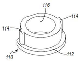
제2 주철 인서트(110)는 단부 플랜지(112), 정반대로 배치되어 있고 축방향으로 연장되는 한 쌍의 웹 또는 리브(114), 및 스터브 샤프트(80)을 수용하는 원형의 관통 개구부(116)를 포함한다. 단부 플랜지(112)는 제2 차동 케이지 또는 하우징(50)의 다이 캐스트 동안 주물(도시되지 않음) 내에서 제2 인서트(110)의 적합한 위치를 지원하고 보장하며, 웹 또는 리브(114)는 제2 차동 케이지 또는 하우징(50) 내에서 제2 인서트(110)의 안전한 부착을 지원하고 회전을 방지한다.The second
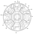
이제 도 2 및 도 4를 참조하면, 제2 차동 케이지 또는 하우징(50)은, 상술한 바와 같이, 볼트 원(bolt circle) 내에 정렬된 복수의 나사 관통 개구부(54)를 포함한다. 또한 케이지 또는 하우징(50)은 비스듬하게 정렬된 복수의 보강 리브(122)를 포함한다. 바람직하게, 리브(122) 중 하나는 각각의 개구부(54)와 관련된다. 제2 차동 케이지 또는 하우징(50)을 통한 윤활유의 이동, 그리고 기어(66L, 66R, 82A 및 82B) 및 스터브 샤프트(80)가 있는 차동 케이지 또는 하우징(50) 내부로의 윤활유의 유입 및 그 내부로부터의 윤활유의 유출을 용이하게 하는 개구부 또는 구멍(124)이 각각의 보강 리브(122) 사이에 배치되어 있다.Referring now to Figures 2 and 4, the second differential cage or
이제 도 2 및 도 5를 참조하면, 제1 차동 허브 또는 하우징(30)은 상술한 바와 같이, 복수의 관통 개구부 또는 구멍(34), 차축(76L)을 수용하도록 적응된 중심 개구부(38), 그리고 마찰방지 볼 베어링 어셈블리(46)를 수용하는 외부 숄더 및 원주 벽(44)을 구비하는 외측 플랜지(32)를 포함한다. 또한, 차동 허브 또는 하우징(30)은 차동 케이지 또는 하우징(50)와 마찬가지로, 차동 허브 또는 하우징(30) 내부로의 윤활유의 유입 및 그 내부로부터의 윤활유의 유출을 용이하게 하는 동일하게 복수의 개구부 또는 구멍(128)과 교대하는 비스듬하게 정렬된 복수의 보강 리브(126)를 포함한다.Referring now to Figures 2 and 5, the first differential hub or
제1 차동 허브 또는 하우징(30) 및 제2 차동 케이지 또는 하우징(50)은 바람직하게 ANSI 383과 같은 알루미늄 합금의 다이 캐스트이거나, 우수한 강도와 주물 특성을 갖는 유사한 재료이다. 철 인서트(90, 110)는 바람직하게 약 3.3%의 탄소, 약 2.30%의 실리콘, 약 .60%의 망간 및 다른 미량원소 또는 유사한 재료를 포함하는 노듈러 주철(nodular cast iron)로 제조된다. 상술한 바와 같이, 철 인서트(90 및 110)는 제2 차동 케이지 또는 하우징(50) 내부에 현장에서 주조된다. "현장 주조(cast in place)"는, 철 인서트(90 및 110)가 처음에 주조되고, 임의의 적절한 가공 또는 표면 마무리 공정에 의해서 마무리되며, 그 다음에 알루미늄으로 추후에 채워지는 제2 차동 케이지 또는 하우징(50)을 위해 주물(도시되지 않음) 내부에 적절하게 위치된다는 것을 의미한다. The first differential hub or
제1 차동 허브 또는 하우징(30) 및 제2 차동 케이지 또는 하우징(50)을 포함하는 차동 장치(20)는 종래 기술의 철 차동 케이지를 능가하는 많은 개선 및 향상을 제공한다. 첫째로, 철 차동 케이지의 중량은 약 1800 그램인데 반해, 차동 허브(30) 및 차동 케이지(50)의 중량은 약 800 그램일 수 있다. 이는 1 kg 또는 약 55%의 중량 감소를 나타낸다. 둘째로, 차동 허브(30)와 차동 케이지(50)가 분리되어 있고, 종래 기술의 케이지에 비해 더 작은 주물이기 때문에, 주물의 정확도 및 무결성이 향상되어, 결함으로 인해 거부되는 주물이 더 적어진다. 또한, 보강 리브(122)는 더 높은 스트레스 영역에 있는 금속에 집중하는 한편, 윤활 개구부(124)는 더 낮은 스트레스의 영역에 있다. 이와 같은 특징의 조합은 중량을 줄여주는 것과 동시에 차동 케이지 또는 하우징(50)의 전체 강도 및 강성을 향상시킨다. 마지막으로, 당연히, 차동 허브(30) 및 차동 케이지(50)의 감소된 중량은 상술한 바와 같이 차량의 중량을 감소시키고 연료 효율을 향상시킨다.A
본 발명의 설명은 본질적으로 예시적인 것에 불과하며, 본 발명의 요지로부터 벗어나지 않는 변경은 본 발명의 범위 내에 속하는 것으로 의도된다. 이와 같은 변경은 본 발명의 사상 및 범위로부터 벗어나는 것으로 간주되지 않는다.The description of the invention is merely exemplary in nature and modifications that do not depart from the gist of the invention are intended to be within the scope of the invention. Such variations are not to be regarded as a departure from the spirit and scope of the invention.
Claims (8)
복수의 치형부, 및 제1 축에 평행하게 정렬된 제1 복수의 개구부를 구비하는 링 기어,
상기 제1 축에 평행하게 정렬된 제2 복수의 개구부, 및 제1 차축을 수용하도록 적응된 상기 제1 축 상의 제1 중심 개구부를 구비하는 차동 허브,
상기 제1 축에 평행하게 정렬되어 있고 나사선을 포함하는 제3 복수의 개구부를 갖는 제2 플랜지, 제2 차축을 수용하도록 적응된 상기 제1 축 상의 제2 중심 개구부, 상기 제1 축에 수직인 제2 축 상의 한 쌍의 관통 개구부를 형성하는 한 쌍의 철 인서트, 상기 철 인서트 내 상기 관통 개구부 내에 배치된 스터브 샤프트, 상기 스터브 샤프트 상에 배치된 한 쌍의 유동 기어, 및 상기 제1 축 상에 배치되어 있고 상기 한 쌍의 유동 기어와 상시 물림상태에 있는 한 쌍의 사이드 기어를 구비하는 차동 하우징을 조합된 형태로 포함하는, 차동장치 어셈블리.A differential assembly comprising:
A ring gear having a plurality of teeth and a first plurality of openings aligned parallel to the first axis,
A differential hub having a second plurality of openings aligned parallel to the first axis and a first central aperture on the first axis adapted to receive a first axle,
A second flange having a third plurality of openings aligned parallel to the first axis and including threads, a second central aperture on the first axis adapted to receive a second axle, A pair of iron inserts forming a pair of through openings on the second axis, a stub shaft disposed in the through-hole in the iron insert, a pair of flow gears disposed on the stub shaft, And a differential housing having a pair of side gears in a normally engaged state with the pair of flow gears in a combined form.
복수의 치형부를 구비하고 제1 축을 형성하는 링 기어,
상기 링 기어에 연결되어 있으며, 상기 제1 축에 평행하게 정렬된 제1 복수의 개구부를 갖는 제1 플랜지, 및 상기 제1 축 상의 제1 중심 개구부를 구비하는 는 제1 알루미늄 차동장치 구성요소,
상기 제1 축에 평행하게 정렬되어 있고 나사선을 포함하는 제3 복수의 개구부를 갖는 제2 플랜지, 제2 차축을 수용하도록 적응된 상기 제1 축 상의 제2 중심 개구부, 상기 제1 축에 수직인 제2 축 상의 한 쌍의 관통 개구부를 형성하는 한 쌍의 철 인서트, 상기 철 인서트 내 상기 관통 개구부 내에 배치된 스터브 샤프트, 상기 스터브 샤프트 상에 배치된 한 쌍의 유동 기어, 및 상기 제1 축 상에 배치되어 있고 상기 한 쌍의 유동 기어와 상시 물림상태에 있는 한 쌍의 사이드 기어를 구비하는 차동 하우징을 조합된 형태로 포함하는, 차동장치 어셈블리.
A differential assembly comprising:
A ring gear having a plurality of teeth and forming a first axis,
A first aluminum differential device component coupled to the ring gear and having a first flange having a first plurality of openings aligned parallel to the first axis and a first central opening on the first axis,
A second flange having a third plurality of openings aligned parallel to the first axis and including threads, a second central aperture on the first axis adapted to receive a second axle, A pair of iron inserts forming a pair of through openings on the second axis, a stub shaft disposed in the through-hole in the iron insert, a pair of flow gears disposed on the stub shaft, And a differential housing having a pair of side gears in a normally engaged state with the pair of flow gears in a combined form.
Applications Claiming Priority (2)
| Application Number | Priority Date | Filing Date | Title |
|---|---|---|---|
| US14/849,127 US9651132B2 (en) | 2015-09-09 | 2015-09-09 | Aluminum differential housing with cast iron inserts |
| US14/849,127 | 2015-09-09 |
Publications (1)
| Publication Number | Publication Date |
|---|---|
| KR20170030431A true KR20170030431A (en) | 2017-03-17 |
Family
ID=58055098
Family Applications (1)
| Application Number | Title | Priority Date | Filing Date |
|---|---|---|---|
| KR1020160108957A KR20170030431A (en) | 2015-09-09 | 2016-08-26 | Aluminum differential housing with cast iron inserts |
Country Status (4)
| Country | Link |
|---|---|
| US (1) | US9651132B2 (en) |
| KR (1) | KR20170030431A (en) |
| CN (1) | CN106523674B (en) |
| DE (1) | DE102016116052B4 (en) |
Families Citing this family (5)
| Publication number | Priority date | Publication date | Assignee | Title |
|---|---|---|---|---|
| US11231099B2 (en) * | 2016-11-09 | 2022-01-25 | Arvinmeritor Technology, Llc | Axle assembly and differential assembly with spider shaft retention |
| KR102394867B1 (en) * | 2017-12-27 | 2022-05-06 | 현대자동차주식회사 | Buried Structure of Cast-Iron Insert for Engine Bed Plate and Method Thereof |
| JP7000216B2 (en) * | 2018-03-20 | 2022-02-04 | トヨタ自動車株式会社 | Transaxle case parts |
| US11878750B2 (en) | 2020-01-17 | 2024-01-23 | Caterpillar Inc. | Wear inserts cast in a wear surface of a drive component |
| CN113145709A (en) * | 2021-02-03 | 2021-07-23 | 重庆大学 | Sheet forming soft die structure with enhanced additive manufacturing insert and manufacturing method thereof |
Family Cites Families (9)
| Publication number | Priority date | Publication date | Assignee | Title |
|---|---|---|---|---|
| US3872741A (en) * | 1973-08-08 | 1975-03-25 | Caterpillar Tractor Co | Differential gear assembly |
| DE19607077C2 (en) * | 1996-02-24 | 1999-04-22 | Getrag Getriebe Zahnrad | Motor vehicle differential |
| US5980417A (en) * | 1998-08-06 | 1999-11-09 | Dana Corporation | Differential case insert |
| US6061907A (en) * | 1998-08-10 | 2000-05-16 | Ford Global Technologies, Inc. | Method for making a differential mechanism for an automotive vehicle |
| DE10338635A1 (en) * | 2003-08-22 | 2005-03-17 | Ina-Schaeffler Kg | Differential gear for vehicles has differential cage rotatable in differential gear housing through ball bearing assembly having bearing pretension produced through plate spring |
| US7341536B2 (en) * | 2005-10-20 | 2008-03-11 | Dana Corporation | Light weight differential case half |
| US7695392B2 (en) * | 2007-07-10 | 2010-04-13 | Ford Global Technologies, Llc | Differential mechanism assembly |
| US8535191B1 (en) * | 2012-07-17 | 2013-09-17 | Gkn Driveline North America, Inc. | Aluminum flange with anti-rotation slots |
| AU2014277689B2 (en) * | 2013-10-23 | 2018-03-08 | Eaton Intelligent Power Limited | Torque limiting differential |
-
2015
- 2015-09-09 US US14/849,127 patent/US9651132B2/en active Active
-
2016
- 2016-08-26 KR KR1020160108957A patent/KR20170030431A/en not_active Application Discontinuation
- 2016-08-29 DE DE102016116052.0A patent/DE102016116052B4/en active Active
- 2016-08-29 CN CN201610751054.0A patent/CN106523674B/en active Active
Also Published As
| Publication number | Publication date |
|---|---|
| CN106523674A (en) | 2017-03-22 |
| DE102016116052B4 (en) | 2023-03-30 |
| US9651132B2 (en) | 2017-05-16 |
| US20170067550A1 (en) | 2017-03-09 |
| DE102016116052A1 (en) | 2017-03-09 |
| CN106523674B (en) | 2019-08-27 |
Similar Documents
| Publication | Publication Date | Title |
|---|---|---|
| KR20170030431A (en) | Aluminum differential housing with cast iron inserts | |
| US11002352B2 (en) | Axle assembly having an axle housing | |
| CN110566651B (en) | Torque transmitting device and collar with concave tooth side surface | |
| US8931373B2 (en) | Drive-force-distribution control device | |
| KR102060545B1 (en) | Aluminum flange with anti-rotation slots | |
| US6379277B1 (en) | Limited slip differential mechanism for an automotive vehicle and method for making the same | |
| US20110303035A1 (en) | Final drive for a work machine | |
| KR101195901B1 (en) | Pinion unit in axle assembly | |
| EP3395599A1 (en) | Bogie axle system | |
| US20070049452A1 (en) | Common center section for independent rear suspension and fixed axle applications | |
| CN107636353A (en) | Final driver | |
| EP2947350A2 (en) | Differential assembly | |
| JP2006266373A (en) | Differential device | |
| US7690449B2 (en) | Output yoke shaft and assembly | |
| JP4577403B2 (en) | Differential gear device for vehicle | |
| US11156281B2 (en) | Axle assembly with lubrication pump | |
| WO2004009392A1 (en) | Inter-axle differential having improved bearing arrangement | |
| CN109869468B (en) | Main reducer assembly and vehicle adopting same | |
| JP6350572B2 (en) | Differential device and manufacturing method thereof | |
| US11079006B2 (en) | Differential unit and differential unit product line | |
| US20240075770A1 (en) | Systems for modular axle housing | |
| US20170082186A1 (en) | Axle assembly | |
| SE2350019A1 (en) | Transmission arrangement for a vehicle | |
| JP2018063039A (en) | Differential device for vehicle | |
| JP2018071563A (en) | Differential device for vehicle |
Legal Events
| Date | Code | Title | Description |
|---|---|---|---|
| A201 | Request for examination | ||
| E902 | Notification of reason for refusal | ||
| E601 | Decision to refuse application |