KR20170026387A - Method and apparatus for predicting image samples for encoding or decoding - Google Patents
Method and apparatus for predicting image samples for encoding or decoding Download PDFInfo
- Publication number
- KR20170026387A KR20170026387A KR1020167036392A KR20167036392A KR20170026387A KR 20170026387 A KR20170026387 A KR 20170026387A KR 1020167036392 A KR1020167036392 A KR 1020167036392A KR 20167036392 A KR20167036392 A KR 20167036392A KR 20170026387 A KR20170026387 A KR 20170026387A
- Authority
- KR
- South Korea
- Prior art keywords
- image
- block
- space
- encoding
- dynamic range
- Prior art date
Links
Images


Classifications
-
- H—ELECTRICITY
- H04—ELECTRIC COMMUNICATION TECHNIQUE
- H04N—PICTORIAL COMMUNICATION, e.g. TELEVISION
- H04N19/00—Methods or arrangements for coding, decoding, compressing or decompressing digital video signals
- H04N19/10—Methods or arrangements for coding, decoding, compressing or decompressing digital video signals using adaptive coding
- H04N19/169—Methods or arrangements for coding, decoding, compressing or decompressing digital video signals using adaptive coding characterised by the coding unit, i.e. the structural portion or semantic portion of the video signal being the object or the subject of the adaptive coding
- H04N19/17—Methods or arrangements for coding, decoding, compressing or decompressing digital video signals using adaptive coding characterised by the coding unit, i.e. the structural portion or semantic portion of the video signal being the object or the subject of the adaptive coding the unit being an image region, e.g. an object
- H04N19/176—Methods or arrangements for coding, decoding, compressing or decompressing digital video signals using adaptive coding characterised by the coding unit, i.e. the structural portion or semantic portion of the video signal being the object or the subject of the adaptive coding the unit being an image region, e.g. an object the region being a block, e.g. a macroblock
-
- H—ELECTRICITY
- H04—ELECTRIC COMMUNICATION TECHNIQUE
- H04N—PICTORIAL COMMUNICATION, e.g. TELEVISION
- H04N19/00—Methods or arrangements for coding, decoding, compressing or decompressing digital video signals
- H04N19/10—Methods or arrangements for coding, decoding, compressing or decompressing digital video signals using adaptive coding
- H04N19/169—Methods or arrangements for coding, decoding, compressing or decompressing digital video signals using adaptive coding characterised by the coding unit, i.e. the structural portion or semantic portion of the video signal being the object or the subject of the adaptive coding
- H04N19/186—Methods or arrangements for coding, decoding, compressing or decompressing digital video signals using adaptive coding characterised by the coding unit, i.e. the structural portion or semantic portion of the video signal being the object or the subject of the adaptive coding the unit being a colour or a chrominance component
-
- H—ELECTRICITY
- H04—ELECTRIC COMMUNICATION TECHNIQUE
- H04N—PICTORIAL COMMUNICATION, e.g. TELEVISION
- H04N19/00—Methods or arrangements for coding, decoding, compressing or decompressing digital video signals
- H04N19/46—Embedding additional information in the video signal during the compression process
-
- H—ELECTRICITY
- H04—ELECTRIC COMMUNICATION TECHNIQUE
- H04N—PICTORIAL COMMUNICATION, e.g. TELEVISION
- H04N19/00—Methods or arrangements for coding, decoding, compressing or decompressing digital video signals
- H04N19/50—Methods or arrangements for coding, decoding, compressing or decompressing digital video signals using predictive coding
- H04N19/503—Methods or arrangements for coding, decoding, compressing or decompressing digital video signals using predictive coding involving temporal prediction
- H04N19/51—Motion estimation or motion compensation
- H04N19/513—Processing of motion vectors
- H04N19/517—Processing of motion vectors by encoding
- H04N19/52—Processing of motion vectors by encoding by predictive encoding
-
- H—ELECTRICITY
- H04—ELECTRIC COMMUNICATION TECHNIQUE
- H04N—PICTORIAL COMMUNICATION, e.g. TELEVISION
- H04N19/00—Methods or arrangements for coding, decoding, compressing or decompressing digital video signals
- H04N19/50—Methods or arrangements for coding, decoding, compressing or decompressing digital video signals using predictive coding
- H04N19/593—Methods or arrangements for coding, decoding, compressing or decompressing digital video signals using predictive coding involving spatial prediction techniques
-
- H—ELECTRICITY
- H04—ELECTRIC COMMUNICATION TECHNIQUE
- H04N—PICTORIAL COMMUNICATION, e.g. TELEVISION
- H04N19/00—Methods or arrangements for coding, decoding, compressing or decompressing digital video signals
- H04N19/90—Methods or arrangements for coding, decoding, compressing or decompressing digital video signals using coding techniques not provided for in groups H04N19/10-H04N19/85, e.g. fractals
- H04N19/98—Adaptive-dynamic-range coding [ADRC]
Abstract
높은 동적 범위 이미지의 적어도 일부분을 인코딩하고 디코딩하는 방법으로서, 이미지는 휘도 성분 및 색차 메트릭을 갖는 고 동적 범위의 지각 공간에서 정의되고, 방법은, 이미지의 적어도 일부분의 블록에 대해, 블록의 예측을 위한 기준 샘플들을 예측될 블록의 LDR 공간으로 컨버팅하는 단계로서, 참조 샘플은 연관된 LDR 공간에서 이전에 재구성된, 상기 컨버팅하는 단계, 및 LDR 이미지에 적용가능한 인코딩 또는 디코딩 기법을 이용하는 블록의 인코딩 또는 디코딩을 위해, 컨버팅된 기준 샘플들을 이용하여 블록을 예측하는 단계를 포함한다.CLAIMS 1. A method for encoding and decoding at least a portion of a high dynamic range image, the image being defined in a high dynamic range perceptual space having a luminance component and a chrominance metric, the method comprising: for a block of at least a portion of the image, Converting the reference samples for a block to be predicted into an LDR space of a block to be predicted, the reference sample having been previously reconstructed in an associated LDR space, converting and encoding or decoding a block using an encoding or decoding technique applicable to the LDR image , ≪ / RTI > using the transformed reference samples.

Description
본 발명은 인코딩 또는 디코딩 프로세스를 위한 이미지 데이터를 예측하기 위한 방법 및 장치에 관한 것이다. 특히, 전적으로는 아니지만, 본 발명은 고 동적 범위 (High Dynamic Range; HDR) 애플리케이션들을 위한 비디오 데이터의 인코딩 및 디코딩을 위한 이미지 데이터의 예측에 관한 것이다.The present invention relates to a method and apparatus for predicting image data for an encoding or decoding process. In particular, but not exclusively, the present invention relates to the prediction of image data for encoding and decoding video data for High Dynamic Range (HDR) applications.
이미징 장치에 의해 캡쳐된 장면의 광의 변화는 크게 달라질 수 있다. 예를 들어, 장면의 그림자에 위치한 오브젝트들은 직사 광선에 의해 조명되는 오브젝트와 비교하여 매우 어둡게 보일 수 있다. 기존의 저 동적 범위 (low dynamic range; LDR) 이미지들이 제공되는 제한된 동적 범위와 색 영역은 그러한 장면 내에서 휘도 및 색에서의 변화들의 정확한 재생을 위한 충분한 범위를 제공하지 않는다. 통상적으로 이미지의 픽셀들의 휘도 또는 색을 표현하는 LDR 이미지들의 성분들의 값들은 제한된 비트들의 수 (통상적으로 8, 10, 또는 12 비트) 로 표현된다. 그러한 표현에 의해 제공되는 휘도의 제한된 범위는, 특히 밝고 어두운 범위의 휘도에서 작은 신호 변동이 효과적으로 재생되는 것을 가능하게 하지 못한다.The change in light of a scene captured by the imaging apparatus can be greatly changed. For example, objects located in the shadows of a scene may look very dark compared to objects illuminated by direct sunlight. The limited dynamic range and color gamut on which existing low dynamic range (LDR) images are provided do not provide sufficient range for accurate reproduction of changes in luminance and color within such a scene. Typically, the values of the components of the LDR images representing the luminance or color of pixels of an image are represented by a limited number of bits (typically 8, 10, or 12 bits). The limited range of luminance provided by such an expression does not enable small signal fluctuations to be effectively reproduced, especially in the bright and dark range of luminance.
고 동적 범위 이미징 (HDR 또는 HDRI 라고도 함) 은 종래의 LDR 이미지들과 비교하여 장면의 밝은 영역과 어두운 영역 사이의 더 큰 동적 범위의 휘도를 가능하게 한다. 이는 전체 범위에 걸쳐 높은 신호 정확도를 제공하기 위해 신호 표현을 더 넓은 동적 범위로 확장함으로써 HDR 이미징에서 달성된다. HDR 이미지들에서, 픽셀들의 성분 값들은 부동-소수점 포맷 (예를 들어, 각각의 성분에 대해 32-비트 또는 16-비트, 즉, 부동 또는 반-부동) - 가장 인기있는 포맷은 openEXR 반-부동 포맷 (RGB 성분당 16-비트, 즉, 픽셀당 48 비트) 이다 -, 또는 긴 표현, 통상적으로 적어도 16 비트를 갖는 정수들을 포함하는 더 많은 수의 비트들 (예를 들어, 16 비트에서 64 비트) 로 보통 표현된다. 그러한 범위들 인간 시각 시스템의 자연스러운 감도에 대응한다. 이러한 방식으로, HDR 이미지들은 실제 장면들에서 발견되는 광범위한 휘도를 보다 정확하게 표현함으로써 장면의 보다 사실적인 표현들을 제공한다.High dynamic range imaging (also referred to as HDR or HDRI) enables a greater dynamic range of brightness between bright and dark areas of the scene compared to conventional LDR images. This is achieved in HDR imaging by extending the signal representation to a wider dynamic range to provide high signal accuracy over the entire range. In HDR images, the component values of pixels are stored in a floating-point format (e.g. 32-bit or 16-bit for each component, i.e. floating or semi-floating) (E.g., 16 bits per RGB component, i.e., 48 bits per pixel), or a larger number of bits (e.g., 16 bits to 64 bits) including integers with long representations, typically at least 16 bits ). Such ranges correspond to the natural sensitivity of the human visual system. In this way, HDR images provide more realistic representations of the scene by more accurately representing the broader brightness found in real scenes.
그러나, 제공되는 값 범위가 더 넓기 때문에, HDR 이미지들은 많은 양의 저장 공간 및 대역폭을 소비하여, HDR 이미지들 및 비디오들의 저장 및 송신에 문제가 되게 한다. 따라서, 보다 작고, 보다 관리하기 쉬운 데이터 사이즈들로 데이터를 압축하기 위해서는 효율적인 코딩 기법들이 요구된다. 정확한 렌더링을 위해 휘도의 동적 범위를 유지하면서 HDR 데이터를 효과적으로 압축하기에 적합한 코딩/디코딩 기법들을 찾는 것은 어려웠다.However, because of the wider range of values provided, HDR images consume a large amount of storage space and bandwidth, making them difficult to store and transmit HDR images and videos. Thus, efficient coding techniques are required to compress data into smaller, more manageable data sizes. It has been difficult to find suitable coding / decoding techniques for efficiently compressing HDR data while maintaining the dynamic range of luminance for accurate rendering.
HDR 이미지를 인코딩하는 통상적인 접근법은 LDR 이미지들을 인코딩하는데 이용되는 종래의 인코딩 스킴으로 이미지를 인코딩하기 위해 이미지의 동적 범위를 감소시키는 것이다.A common approach to encoding HDR images is to reduce the dynamic range of the image to encode the image with a conventional encoding scheme used to encode the LDR images.
예를 들어, 한 가지 그러한 기법에서, 톤-맵핑 오퍼레이터가 입력 HDR 이미지에 적용되고, 톤-맵핑된 이미지는 그 다음에 JPEG/JPEG200 또는 MPEG-2, 비디오용 H.264/AVC 와 같은 종래의 8-10 비트 심도 인코딩 기법에 의해 인코딩된다 (Karsten Suhring, H.264/AVC Reference Software, http://iphome.hhi.de/suehring/tml/download/, the book of I. E. Richardson titled << H.264 and MPEG-4 video compression >> 2003 년 9 월에 J. Wiley & Sons 에서 공개됨). 역 톤-맵핑 오퍼레이터가 그 다음에 디코딩된 이미지에 적용되고, 입력 이미지와 디코딩되고 역-톤-맵핑된 이미지 사이에 잔여가 계산된다. 마지막으로, 잔여는 제 2 종래의 8-10 비트-심도 인코더 스킴에 의해 인코딩된다.For example, in one such technique, a tone-mapped operator is applied to the input HDR image and the tone-mapped image is then combined with a conventional JPEG / JPEG 200 or MPEG-2, H.264 / 8-10 bit depth encoding technique (Karsten Suhring, H.264 / AVC Reference Software, http://iphome.hhi.de/suehring/tml/download/, the book of IE Richardson titled << H. 264 and MPEG-4 video compression ", published by J. Wiley & Sons, September 2003). A reverse tone-mapping operator is then applied to the decoded image, and the residual between the input image and the decoded and back-ton-mapped image is calculated. Finally, the remainder is encoded by a second conventional 8-10 bit-depth encoder scheme.
이 첫 번째 접근법의 주된 단점들은 두 가지 인코딩 스킴들의 이용, 및 입력 이미지의 동적 범위를 종래의 인코딩 스킴의 동적 범위 (16-20 비트) 의 두 배로의 제한이다. 다른 접근법에 따르면, 값들이, 예를 들어, HEVC (B. Bross, W.J. Han, G. J. Sullivan, J.R. Ohm, T. Wiegand JCTVC-K1003, "High Efficiency Video Coding (HEVC) text specification draft 9," Oct 2012) 및 그것의 높은 비트-심도 확장안들과 같은, 종래의 8-10 또는 확장된 12, 14, 또는 16 비트 심도 인코딩 스킴과 호환가능한 동적 범위에 속하는 색 공간에서 이미지 픽셀들의 시각적 무손실 표현을 획득하도록 입력 HDR 이미지가 컨버팅된다. 종래의 코덱들이 높은 픽셀 (비트) 심도들을 오퍼레이팅할 수 있다고 하더라도, 획득된 압축 비율이 송신 애플리케이션들에 있어 너무 낮기 때문에 일반적으로 이미지 전체에 걸쳐 균일한 방식으로 그러한 비트 심도들로 인코딩하기가 어렵다.The main disadvantages of this first approach are the use of two encoding schemes and the limitation of the dynamic range of the input image to twice the dynamic range (16-20 bits) of the conventional encoding scheme. According to another approach, the values are compared with the values obtained by the HEVC (B. Bross, WJ Han, GJ Sullivan, JR Ohm, T. Wiegand JCTVC-K1003, "High Efficiency Video Coding To obtain a visual lossless representation of image pixels in a color space that is compatible with conventional 8-10 or extended 12, 14, or 16 bit depth encoding schemes, such as high bit-depth expansion planes The input HDR image is converted. Even though conventional codecs are capable of operating high pixel depths, it is generally difficult to encode such bit depths in a uniform manner throughout the image, since the obtained compression ratio is too low for transmitting applications.
LDR 이미지들에 적용가능한 코딩 기법들을 이용하는 다른 접근법들은 디코딩 된 이미지에 아티팩트들을 초래한다. 본 발명은 앞서의 것을 염두에 두고 고안되었다.Other approaches that use coding techniques applicable to LDR images result in artifacts in the decoded image. The present invention has been devised with the foregoing in mind.
본 발명의 제 1 양태에 따르면, 고 동적 범위 이미지의 적어도 일부분을 인코딩하고 디코딩하는 방법이 제공되며, 고 동적 범위의 색 공간에서 이미지는 정의되고, 방법은, 이미지의 적어도 일부분의 블록에 대해, 블록의 예측을 위한 기준 샘플들을 예측될 블록의 로컬 지각 LDR 공간으로 컨버팅하는 단계로서, 기준 샘플들은 그것들의 연관된 로컬 LDR 색 공간에서 이전에 재구성되는, 상기 컨버팅하는 단계, 및 LDR 이미지에 적용가능한 인코딩 또는 디코딩 기법을 이용하는 블록의 인코딩 또는 디코딩을 위해, 컨버팅된 기준 샘플들을 이용하여 블록을 예측하는 단계를 포함한다. 블록의 로컬 LDR 지각 공간은 블록의 대표적인 휘도에 기초한 블록의 기준 조명 조건들에 의해 특징지어질 수도 있다. 예를 들어, 기준 조명 조건들은 블록의 평균 휘도 값들로부터 도출될 수도 있다.According to a first aspect of the present invention there is provided a method of encoding and decoding at least a portion of a high dynamic range image, the image being defined in a high dynamic range color space, the method comprising: Converting the reference samples for prediction of a block into a local perceptual LDR space of a block to be predicted, wherein the reference samples are previously reconstructed in their associated local LDR color space; and converting the encoding applicable to the LDR image Or predicting the block using the converted reference samples, for encoding or decoding of the block using the decoding technique. The local LDR perception space of the block may be characterized by the reference illumination conditions of the block based on the representative luminance of the block. For example, the reference illumination conditions may be derived from the average luminance values of the block.
일 실시예에서, 기준 샘플들의 컨버젼은:In one embodiment, the conversion of the reference samples comprises:
개개의 재구성된 LDR 공간으로부터 고 동적 범위의 로컬 지각 공간으로의 기준 샘플들의 스케일링;Scaling the reference samples from the individual reconstructed LDR space to the high dynamic range local perceptual space;
이미지의 원래의 HDR 공간에서 스케일링된 기준 샘플들의 재구성;Reconstruction of scaled reference samples in the original HDR space of the image;
재구성된 스케일링된 기준 샘플들의 예측될 블록의 로컬 지각 공간으로의 맵핑; 및 Mapping the reconstructed scaled reference samples to the local perceptual space of the block to be predicted; And
예측될 블록의 인코딩/디코딩에 이용된 컨버팅된 기준 샘플들의 동적 범위의 LDR 공간으로의 감소를 포함한다.To the LDR space of the dynamic range of the converted reference samples used for encoding / decoding of the block to be predicted.
일 실시예에서, 원래의 HDR 공간에서 스케일링된 샘플들의 재구성은 기준 샘플들과 각각 연관된 공통 대표 휘도 성분들에 의존한다.In one embodiment, the reconstruction of the scaled samples in the original HDR space is dependent on the common representative luminance components associated with the reference samples, respectively.
일 실시예에서, 예측될 블록의 로컬 HDR 공간으로의 재구성된 스케일링된 샘플들의 맵핑은 예측될 블록과 연관된 공통 대표 휘도 성분 값에 의존한다. 각각의 공통 대표 휘도 성분은 기준 샘플이 속하는 블록을 구성하는 샘플들의 휘도를 표현할 수도 있다.In one embodiment, the mapping of the reconstructed scaled samples into the local HDR space of the block to be predicted depends on the value of the common representative luminance component associated with the block to be predicted. Each common representative luminance component may express the luminance of the samples constituting the block to which the reference sample belongs.
일 실시예에서, 기준 샘플에 대한 상기 공통 대표 휘도 성분 값은 그 기준 샘플이 속하는 이미지 블록의 이미지 샘플들의 휘도 값들에 기초하여 획득된다.In one embodiment, the common representative luminance component value for the reference sample is obtained based on the luminance values of the image samples of the image block to which the reference sample belongs.
일 실시예에서, 예측될 블록에 대한 공통 대표 휘도 성분 값은 상기 블록의 이미지 샘플들의 휘도 값들에 기초하여 획득된다.In one embodiment, the common representative luminance component value for the block to be predicted is obtained based on the luminance values of the image samples of the block.
일 실시예에서, 방법은, 적어도 하나의 코딩 파라미터를 포함하는 코딩 파라미터 세트를 적용함으로써 저 동적 범위 (LDR) 이미지에 적용가능한 인코딩 프로세스를 이용하여 이미지의 적어도 일부분의 블록을 인코딩하는 단계; 고 동적 범위의 공간에서 인코딩된 블록을 재구성하는 단계; 고 동적 범위의 공간에서 인코딩된 블록에 대한 레이트 왜곡 비용을 평가하는 단계; 및 평가된 레이트 왜곡 비용에 기초하여 블록의 인코딩 프로세스에 대해 상기 코딩 파라미터 세트를 조정하는 단계를 포함한다.In one embodiment, a method includes encoding a block of at least a portion of an image using an encoding process applicable to a low dynamic range (LDR) image by applying a set of coding parameters including at least one coding parameter; Reconstructing an encoded block in a high dynamic range of space; Evaluating a rate distortion cost for an encoded block in a high dynamic range of space; And adjusting the coding parameter set for the encoding process of the block based on the estimated rate distortion cost.
일 실시예에서, 레이트 왜곡 비용을 평가하는 단계는 인코딩될 블록의 공통 대표 성분 값의 인코딩과 연관된 레이트를 평가하는 단계를 포함한다.In one embodiment, evaluating the rate distortion cost comprises evaluating a rate associated with encoding the common representative component value of the block to be encoded.
일 실시예에서, 예측될 이미지 블록은 블록의 인코딩 이전에 대응하는 공통 대표 휘도 성분 값에 기초하여 고 동적 범위의 로컬 지각 공간에서 표현된다.In one embodiment, the image block to be predicted is represented in a high dynamic range local perceptual space based on the corresponding common representative luminance component value prior to the encoding of the block.
일 실시예에서, 방법은 예측될 블록에 대해 저 동적 범위의 로컬 공간에서 적어도 하나의 로컬 잔여 휘도 성분을 획득하는 단계를 포함하며, 상기 적어도 하나의 로컬 잔여 휘도 성분은 원래 이미지의 대응하는 휘도 성분과 블록의 공통 대표 휘도 값 사이의 차이에 대응한다.In one embodiment, the method includes obtaining at least one local residual luminance component in a low dynamic range local space for a block to be predicted, wherein the at least one local residual luminance component is a corresponding luminance component of the original image And the common representative luminance value of the block.
일 실시예에서, 방법은 블록에 대해 로컬 지각 공간에서의 적어도 하나의 이미지 부분을 획득하는 단계를 포함하며, 상기 적어도 하나의 이미지 부분은 블록의 적어도 하나의 공통 대표 휘도 값에 따라 정규화된, 이미지 부분의 로컬 잔여 휘도 성분 또는 색 성분에 대응한다.In one embodiment, the method includes obtaining at least one image portion in a local perception space for a block, wherein the at least one image portion is an image normalized according to at least one common representative luminance value of the block, Corresponding to the local residual luminance component or chrominance component of the portion.
일 실시예에서, 레이트 왜곡 비용을 평가하는 단계는 상기 적어도 하나의 이미지 부분의 인코딩과 연관된 레이트를 평가하는 단계를 포함한다.In one embodiment, evaluating the rate distortion cost comprises evaluating a rate associated with encoding of the at least one image portion.
일 실시예에서, 레이트 왜곡 비용을 평가하는 단계는 고 동적 범위의 지각 공간에서 인코딩된 블록의 재구성과 연관된 왜곡을 평가하는 단계를 포함한다.In one embodiment, evaluating the rate distortion cost includes evaluating the distortion associated with the reconstruction of the encoded block in the high dynamic range perceptual space.
일 실시예에서, 방법은 로컬 지각 공간에서 재구성된 잔여 이미지 부분의 샘플들 및 원래의 텍스쳐의 샘플들 및 상기 이미지의 대응하는 샘플들 사이에서 가상 무손실 정제를 수행하는 단계를 포함한다.In one embodiment, the method includes performing virtual lossless purification between samples of the reconstructed residual image portion in the local perception space and samples of the original texture and corresponding samples of the image.
본 발명의 제 2 양태는 휘도 성분 및 색차 메트릭을 갖는 지각 공간에서 정의된 고 동적 범위의 이미지의 적어도 일부분을 인코딩하기 위한 인코딩 디바이스를 제공하며, 디바이스는 블록의 예측을 위한 기준 샘플들을 예측될 이미지 블록의 LDR 공간으로 컨버팅하기 위한 기준 샘플 컨버터로서, 기준 샘플들은 그것들의 관련 LDR 공간에서 이전에 재구성되는, 상기 기준 샘플 컨버터, 및 컨버팅된 기준 샘플들을 이용하여 블록을 예측하기 위한 예측 모듈, LDR 이미지에 적용가능한 인코딩 기법을 이용하여 블록을 인코딩하기 위한 인코더를 포함한다.A second aspect of the present invention provides an encoding device for encoding at least a portion of a high dynamic range image defined in a perceptual space having a luminance component and a chrominance metric, the device comprising: A reference sample converter for converting the reference samples into their LDR space, the reference samples being reconstructed previously in their associated LDR space, the reference sample converter, and a prediction module for predicting the block using the converted reference samples, And an encoder for encoding the block using an encoding technique applicable to the encoder.
본 발명의 제 2 양태에 따른 인코딩 디바이스는 본 발명의 제 1 양태의 실시예의 방법을 수행하도록 구성될 수도 있다.An encoding device according to the second aspect of the present invention may be configured to perform the method of the embodiment of the first aspect of the present invention.
본 발명의 제 3 양태는 휘도 성분 및 색차 메트릭을 갖는 지각 공간에서 정의된 고 동적 범위의 이미지의 적어도 일부분을 디코딩하기 위한 디코딩 디바이스를 제공하며, 그 디바이스는:A third aspect of the present invention provides a decoding device for decoding at least a portion of a high dynamic range image defined in a perceptual space having a luminance component and a chrominance metric, the device comprising:
LDR 이미지에 적용가능한 디코딩 기법을 이용하여 이미지 블록을 디코딩하기 위한 디코더,A decoder for decoding an image block using a decoding technique applicable to an LDR image,
블록의 예측을 위한 기준 샘플들을 예측될 블록의 LDR 공간으로 컨버팅하기 위한 기준 샘플 컨버터로서, 기준 샘플들은 이전에 그것들의 연관된 LDR 공간에서 재구성된, 상기 기준 샘플 컨버터, 및A reference sample converter for converting reference samples for prediction of a block into an LDR space of a block to be predicted, the reference samples being reconstructed in their associated LDR space;
컨버팅된 기준 샘플들을 이용하여 블록을 예측하기 위한 예측 모듈을 포함한다.And a prediction module for predicting the block using the converted reference samples.
본 발명의 제 3 또는 제 4 양태에서, 기준 샘플 컨버터는,In a third or fourth aspect of the invention, the reference sample converter comprises:
개개의 재구성된 LDR 공간으로부터 고 동적 범위의 로컬 지각 공간으로 기준 샘플들을 스케일링하고;Scaling the reference samples from the respective reconstructed LDR space to a high dynamic range local perceptual space;
이미지의 원래의 HDR 공간에서 스케일링된 기준 샘플들을 재구성하고;Reconstructing the scaled reference samples in the original HDR space of the image;
재구성된 스케일링된 기준 샘플들을 예측될 블록의 로컬 지각 공간으로 맵핑하고;Map the reconstructed scaled reference samples to the local perceptual space of the block to be predicted;
예측될 블록의 인코딩/디코딩에 이용된 컨버팅된 기준 샘플들의 동적 범위의 LDR 공간으로의 감소를 수행하도록 구성된 하나 이상의 프로세서들을 포함할 수도 있다.And to perform a reduction to the LDR space of the dynamic range of the converted reference samples used for encoding / decoding of the block to be predicted.
본 발명의 실시예들은 개선된 시각적 경험을 제공하는 광범위한 애플리케이션에 대한 고 동적 범위 이미지 데이터를 위한 인코딩 및 디코딩 방법들을 제공한다.Embodiments of the present invention provide encoding and decoding methods for high dynamic range image data for a wide range of applications that provide an improved visual experience.
본 발명에 따른 방법들 중 적어도 부분들은 컴퓨터로 구현될 수도 있다. 이에 따라, 본 발명은 여기서는 모두가 "회로", "모듈", 또는 "시스템" 으로서 일반적으로 지칭될 수도 있는 완전 하드웨어 실시예, 완전 소프트웨어 실시예 (펌웨어, 상주형 소프트웨어, 마이크로코드 등을 포함), 또는 소프트웨어와 하드웨어 양태들을 결합하는 실시예의 형태를 취할 수 있다. 또한, 본 발명은 매체에서 구현되는 컴퓨터 이용가능 프로그램 코드를 갖는 표현의 임의의 유형 매체에서 구현되는 컴퓨터 프로그램 제품의 형태를 취할 수도 있다.At least portions of the methods according to the present invention may be implemented in a computer. Accordingly, the present invention may be embodied in a complete hardware embodiment, a complete software embodiment (including firmware, resident software, microcode, etc.), all of which may be generally referred to herein as a "circuit ", & , Or an embodiment combining software and hardware aspects. The invention may also take the form of a computer program product embodied in any type of medium of representation having computer usable program code embodied in the medium.
본 발명이 소프트웨어로 구현될 수도 있기 때문에, 본 발명은 임의의 적절한 캐리어 매체 상에서 프로그래밍가능한 장치에 대한 제공을 위한 컴퓨터 판독가능 코드로서 구현될 수도 있다. 유형의 캐리어 매체는 저장 매체, 예컨대, 플로피 디스크, CD-ROM, 하드 디스크 드라이브, 자기 테이프 디바이스, 또는 솔리드 스테이트 메모리 디바이스 등을 포함할 수도 있다. 일시적 캐리어 매체는 신호, 예컨대, 전기 신호, 전자 신호, 광학 신호, 음향 신호, 자기 신호 또는 전자기 신호, 예를 들어, 마이크로파 또는 RE 신호를 포함할 수도 있다.As the present invention may be implemented in software, the present invention may be embodied as computer readable code for providing a programmable device on any suitable carrier medium. Type carrier media may include storage media, such as floppy disks, CD-ROMs, hard disk drives, magnetic tape devices, or solid state memory devices, and the like. The transitory carrier medium may comprise a signal, e.g., an electrical signal, an electronic signal, an optical signal, an acoustic signal, a magnetic signal, or an electromagnetic signal, e.g., a microwave or RE signal.
본 발명의 실시형태들은 이제 단지 일 예로 그리고 다음의 도면들을 참조하여 설명될 것이다:
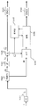
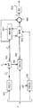
도 1 은 본 발명의 제 1 실시형태에 따른 인코딩 프로세스의 블록도이다;
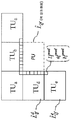
도 2 는 HEVC 비디오 압축 표준에 따른 예측 유닛들 및 변환 유닛들로의 코딩 유닛의 분해의 예를 예시하는 개략도이다;
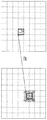
도 3 은 인트라 예측 방법들의 예들을 예시하는 개략도이다;
도 4 는 본 발명의 실시형태에 따른 기준 샘플 변환 프로세스의 플로우 차트이다;
도 5 는 본 발명의 실시형태에 따른 인트라 예측의 예를 예시하는 블록도이다;
도 6 은 본 발명의 실시형태에 따른 인터 예측의 예를 예시하는 블록도이다;
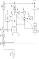
도 7 은 본 발명의 추가 실시형태에 따른 인코딩 프로세스의 블록도이다;
도 8 은 본 발명의 추가 실시형태에 따른 인코딩 프로세스의 블록도이다;
도 9 는 본 발명의 하나 이상의 실시형태들에 따른 디코딩 프로세스의 블록도이다;
도 10 은 본 발명의 하나 이상의 실시형태들에 따른 디코딩 프로세스의 블록도이다;
도 11 은 본 발명의 하나 이상의 실시형태들이 구현될 수 있는 인코딩 또는 디코딩 디바이스의 블록도이다;
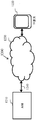
도 12 는 본 발명의 하나 이상의 실시형태들이 구현될 수 있는 데이터 통신 시스템의 예의 블록도이다;
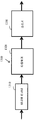
도 13 은 본 발명의 하나 이상의 실시형태들이 구현될 수 있는 데이터 송신기 시스템의 예의 블록도이다; 그리고
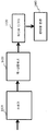
도 14 는 본 발명의 하나 이상의 실시형태들이 구현될 수 있는 데이터 수신기 시스템의 예의 블록도이다.Embodiments of the present invention will now be described, by way of example only and with reference to the accompanying drawings, in which:
1 is a block diagram of an encoding process according to a first embodiment of the present invention;
2 is a schematic diagram illustrating an example of decomposition of a coding unit into prediction units and conversion units according to the HEVC video compression standard;
3 is a schematic diagram illustrating examples of intra prediction methods;
4 is a flowchart of a reference sample conversion process according to an embodiment of the present invention;
5 is a block diagram illustrating an example of intra prediction according to an embodiment of the present invention;
6 is a block diagram illustrating an example of inter prediction according to an embodiment of the present invention;
Figure 7 is a block diagram of an encoding process in accordance with a further embodiment of the present invention;
8 is a block diagram of an encoding process in accordance with a further embodiment of the present invention;
9 is a block diagram of a decoding process in accordance with one or more embodiments of the present invention;
Figure 10 is a block diagram of a decoding process in accordance with one or more embodiments of the present invention;
Figure 11 is a block diagram of an encoding or decoding device in which one or more embodiments of the present invention may be implemented;
12 is a block diagram of an example of a data communication system in which one or more embodiments of the present invention may be implemented;
13 is a block diagram of an example of a data transmitter system in which one or more embodiments of the present invention may be implemented; And
14 is a block diagram of an example of a data receiver system in which one or more embodiments of the present invention may be implemented.
도 1 은 본 발명의 제 1 실시형태에 따른 이미지 (I) 의 적어도 일부를 인코딩하기 위한 방법의 단계들을 예시하는 개략적 블록도이다. 도 1 의 방법의 인코딩 단계들은 일반적으로 LDR 타입 이미지들에 적용가능한 HEVC 압축 표준에 기초하지만 본 발명의 실시형태들이 예를 들어 H.264/AVC, MPEG2 또는 MPEG4 와 같은 LDR 타입 이미지들에 적용가능한 다른 인코딩 표준들에 적용될 수도 있다는 것이 인식될 것이다.1 is a schematic block diagram illustrating steps of a method for encoding at least a portion of an image (I) in accordance with a first embodiment of the present invention. The encoding steps of the method of FIG. 1 are generally based on the HEVC compression standard applicable to LDR type images, but the embodiments of the present invention are applicable to LDR type images such as H.264 / AVC, MPEG2 or MPEG4 But may be applied to other encoding standards.
방법은 HDR 이미지 데이터의 획득 (acquisition) 으로 시작한다. HDR 이미지 데이터는 이미지들의 비디오 시퀀스, 이미지 또는 이미지의 일부를 나타낼 수도 있다. 다음에 오는 설명을 단순화하는 목적들을 위해, 획득된 이미지 데이터는 HDR 이미지에 대응한다. HDR 이미지 데이터는 비디오 카메라와 같은 이미징 디바이스로부터 직접 획득되거나, 그 이미지 데이터가 저장되는 로컬로 또는 원격으로 위치된 메모리 디바이스로부터 획득되거나, 또는 무선 또는 유선 송신 라인을 통해 수신될 수도 있다.The method begins with an acquisition of HDR image data. The HDR image data may represent a video sequence of images, an image, or a portion of an image. For purposes of simplifying the description that follows, the acquired image data corresponds to an HDR image. The HDR image data may be obtained directly from an imaging device, such as a video camera, or may be obtained from a locally or remotely located memory device in which the image data is stored, or received via a wireless or wired transmission line.
본 명세서에서 사용한 바와 같이, 용어 "HDR 이미지" 는 부동 소수점 (부동 (float) 또는 반 부동 (half float)), 고정 소수점 또는 16 보다 큰 비트들의 수로 통상 표현되는 긴 표현 정수 포맷의 고 동적 범위 데이터를 포함하는 임의의 HDR 이미지를 지칭한다. 입력 HDR 이미지는 임의의 색 또는 지각 공간으로 정의될 수도 있다 예를 들어, 본 실시형태에서, 입력 HDR 이미지는 RGB 색 공간으로 정의된다. 다른 실시형태에서, 입력 HDR 이미지는 YUV 또는 임의의 지각 공간과 같은 다른 색 공간으로 정의될 수도 있다. 입력 HDR 이미지는 또한, 선형 또는 비선형 표현, 예를 들어, 감마 보정/변환으로부터 이슈된 로가리즘 표현으로 정의될 수도 있다.As used herein, the term "HDR image" refers to a high dynamic range data in a long presentation integer format, typically represented as a floating point (float or half float), fixed point, Quot; HDR " The input HDR image may be defined as any color or perceptual space. For example, in this embodiment, the input HDR image is defined as an RGB color space. In another embodiment, the input HDR image may be defined as another color space, such as YUV or any perceptual space. The input HDR image may also be defined as a linear or nonlinear representation, for example, a logarithmic representation from the gamma correction / conversion.
일반적으로, 프로세스의 인코딩 단계들은 이미지의 픽셀들의 휘도를 나타내는 데이터를 포함하는 데이터에 대해 수행된다. 이러한 이미지 데이터는 휘도 성분 (L) 및 잠재적으로 적어도 하나의 색 또는 크로마 성분 C(i) 를 포함하고, 여기서 i 는 이미지의 색 또는 크로마 성분을 식별하는 인덱스이다. 이미지의 성분들은 색 공간, 보통 3D 공간을 정의하고, 예를 들어, 이미지는 휘도 성분 (L) 및 잠재적으로 2 개의 색 성분들 (C1 및 C2) 을 포함하는 색 지각 공간으로 정의될 수도 있다.Generally, the encoding steps of the process are performed on data including data indicative of the brightness of the pixels of the image. This image data includes a luminance component L and potentially at least one color or chroma component C (i), where i is an index that identifies the color or chroma component of the image. The components of the image define a color space, usually a 3D space, for example, an image may be defined as a color perception space comprising a luminance component L and potentially two color components C1 and C2.
그러나, 본 발명은 색 성분들을 갖는 HDR 이미지로 한정되지는 않는다는 것이 인식될 것이다. 예를 들어, HDR 이미지는 어떤 색 성분 없이도 휘도 성분을 갖는 지각 공간에서의 그레이 이미지일 수도 있다.However, it will be appreciated that the present invention is not limited to HDR images having color components. For example, an HDR image may be a gray image in a perceptual space with a luminance component without any color components.
지각 공간은 휘도 성분을 포함하는 복수의 성분들에 의해 정의된 색 공간으로서 정의되고 값들이 상기 지각 공간의 2 개의 포인트들의 시지각들 간의 각각의 차이들을 나타내고, 바람직하게는 그 각각의 차이들에 비례하는 색 차이 메트릭 ![]()
![]()
수학적으로 말하면, 색 차이 메트릭 ![]()
![]()
![]()
![]()
![]()
![]()
에서는, 눈이 지각 공간의 2 개의 색들 간의 시각 차이를 지각하는 것이 불가능하다. , It is impossible for the eye to perceive the visual difference between the two colors of the perception space.
지각 임계치 ![]()
![]()
![]()
![]()
획득된 이미지 (I) 가 예를 들어 (R,G,B) 와 같은 비-지각 공간에 속하는 성분들을 포함할 때, 지각 공간을 정의하는 휘도 성분 (L) 및 잠재적으로 적어도 하나의 색 성분, 예를 들어, 휘도 성분 (L) 및 2 개의 색 성분들 (C1 및 C2) 을 갖는 HDR 이미지 (Ip) 를 획득하기 위하여 지각 변환이 단계 S101 에서 이미지 변환 모듈 (IC) 에 의해 이미지 데이터 (I) 에 적용된다.When the acquired image I comprises components belonging to a non-perceptual space, for example (R, G, B), a luminance component L defining the perception space and potentially at least one color component, For example, in order to obtain an HDR image (I p ) having a luminance component (L) and two color components (
수행된 지각 변환은 디스플레이의 라이팅 조건들에 그리고 초기 색 공간에 의존한다. 예를 들어, 초기 색 공간이 (R,G,B) 색 공간인 것을 가정하면, 이미지 (I) 는 잘 알려진 선형 공간 (X,Y,Z) 으로 먼저 변환된다. 이 단계는 적절한 경우, 역 감마 보정을 적용하고 그 후 선형 RGB 공간 데이터를 3x3 변환 매트릭스를 가진 XYZ 공간으로 변환함으로써, 데이터의 선형화를 수행하는 것을 포함한다. 이 단계 동안에는, 이미지의 시각 환경을 특성화하는 데이터가 이용된다. 예를 들어, (X,Y,Z) 공간에서의 디스플레이의 기준 라이팅 조건들을 정의하는 값들 (Xn,Yn,Zn) 의 3D 벡터가 이용될 수도 있다.The perceptual transformation performed depends on the lighting conditions of the display and on the initial color space. For example, assuming that the initial color space is a (R, G, B) color space, the image I is first transformed into a well-known linear space (X, Y, Z). This step involves performing linearization of the data by applying inverse gamma correction, if appropriate, and then converting the linear RGB spatial data into XYZ space with a 3x3 transformation matrix. During this step, data is used that characterize the visual environment of the image. For example, a 3D vector of values (X n , Y n , Z n ) defining the reference lighting conditions of the display in the (X, Y, Z) space may be used.
일 예로서, 지각 변환은 지각 공간 LabCIE1976 이 선택되는 경우에 다음과 같이 정의되고 :As an example, the crustal transformation is defined as follows when the perception space LabCIE1976 is selected:

여기서 f 는 예를 들어, 다음에 의해 주어진 감마 보정 함수이다:Where f is, for example, the gamma correction function given by:

2 개의 색들은 지각 공간 LabCIE1976 에 대해 정의된 다음의 색 차이 메트릭이 충족될 때 기준 라이팅 조건들 (Xn,Yn,Zn) 에서 서로 인간적으로 구별가능하고:The two colors are humanly distinguishable from each other in the reference lighting conditions (X n , Y n , Z n ) when the following color difference metric defined for the perception space LabCIE1976 is satisfied:
![]()
![]()
여기서 는 2 개의 색들 ![]()
![]()
![]()
![]()
![]()
![]()
![]()
![]()
![]()
![]()
공간 (X,Y,Z) 에서의 이미지는 일부 경우들에서, 본 예에서는 (R,G,B) 공간과 같은 초기 공간에서 디코딩된 이미지의 추정치를 획득하도록 역 변환될 수도 있다. 대응하는 역 지각 변환은 다음에 의해 주어진다:The image in space (X, Y, Z) may be inversely transformed to obtain an estimate of the decoded image in an initial space, such as (R, G, B) space in this example in this example. The corresponding inverse crustal transformation is given by:

다른 예에 따르면, 지각 공간 ![]()
![]()
![]()
![]()
![]()
![]()
여기서 다음이 정의된다:Here, the following is defined:
![]()
![]()
및And
![]()
![]()
다음의 유클리드 메트릭은 지각 공간 ![]()
![]()
![]()
![]()
여기서 ![]()
![]()
![]()
![]()
![]()
![]()
![]()
![]()
Luv 공간에 대한 대응하는 역 지각 변환은 다음에 의해 주어진다:The corresponding inverse crustal transformation for Luv space is given by:

본 발명은 지각 공간 LabCIE1976 에 제한되지 않고 동일한 Lab 공간이지만 지각 거리를 측정하기 위한 상이한 메트릭을 가진 LabCIE1994, LabCIE2000 과 같은 임의의 타입의 지각 공간으로, 또는 예를 들어, 임의의 다른 유클리드 지각 공간으로 확장될 수도 있다는 것이 인식될 것이다.The present invention is not limited to the perception space LabCIE1976 but extends to any type of perception space, such as LabCIE1994, LabCIE2000, which has the same Lab space but different metrics for measuring the perception distance, or for example, to any other Euclidean perturbed space ≪ / RTI >
다른 예들은 LMS 공간들 및 IPT 공간들이다. 이러한 지각 공간들에서, 메트릭은, 바람직하게는 지각 차이에 비례하도록 정의된다; 그 결과, 동종의 최대 지각 임계치 ![]()
![]()
단계 S102 에서, 이미지는 파티셔닝 모듈 PART1 에 의해, 일련의 공간 유닛들로 공간 분해된다. 이미지들의 인코딩에서 HEVC 비디오 압축 기법에 따른 공간 코딩 구조들의 일 예가 도 2 에 예시된다. HEVC 타입 인코더의 경우에, 가장 큰 공간 유닛은 코딩 트리 유닛 (CTU) 으로 지칭된다. 각각의 공간 유닛은 쿼드-트리로 종종 지칭되는, 코딩 파라미터들에 의해 나타내진, 분해 구성에 따른 추가 엘리먼트들로 분해된다. 쿼드-트리의 각각의 리프는 코딩 유닛 (CU) 이라 불리고, 샘플들이 공통 예측 파라미터들을 공유하는, 예측 유닛들 (PU) 로 지칭된 하나 이상의 서브-엘리먼트들로, 및 프로세싱 블록 사이즈를 정의하는 변환 유닛들 (TU) 로 추가 파티셔닝된다.In step S102, the image is spatially decomposed into a series of spatial units by the partitioning module PART1. An example of spatial coding schemes according to the HEVC video compression scheme in the encoding of images is illustrated in FIG. In the case of an HEVC type encoder, the largest spatial unit is referred to as a coding tree unit (CTU). Each spatial unit is decomposed into additional elements according to the decomposition scheme, denoted by the coding parameters, often referred to as quadtrees. Each leaf of the quad-tree is called a coding unit (CU) and is divided into one or more sub-elements, referred to as prediction units (PU), in which the samples share common predictive parameters, Are further partitioned into units TU.
도 1 의 예의 단계 S102 에서, 코딩 유닛은, 본 예에서 본 발명의 실시형태들에 따른 예측 기반 인코딩을 위한 예측 유닛들 (PU) 에 대응하는 하나 이상의 서브-엘리먼트들 또는 블록들 (BI) 로 파티셔닝된다.In step S102 of the example of FIG. 1, the coding unit comprises, in this example, one or more sub-elements or blocks BI corresponding to prediction units (PU) for prediction-based encoding according to embodiments of the present invention Partitioned.
도 3 은 HEVC 표준에서 적용된 공간 예측 방법들의 예들을 예시한다. 예측 기반 인코딩 또는 디코딩 방법들에서, 재구성될 공간 블록은 예측자로 통상 지칭되는 기준 샘플로부터 예측된다. 예측자는 인터 예측의 경우에, 프레임들의 시퀀스의 상이한 프레임에서 또는 인트라 예측의 경우에서와 같이 예측될 블록과 동일한 프레임에 위치될 수도 있다. 인트라 예측의 경우에, 예측자들은 방향성 모드 또는 비-방향성 모드에 대응할 수 있는 예측 모드에 의해 나타내진다. 인터 예측의 경우에, 예측자들은 예측 타입 (단- 또는 양-예측), 프레임 인덱스들 및 모션 벡터들에 의해 나타내질 수 있다. 예측 인코딩 또는 디코딩 절차들은 블록을 예측하는데 있어서 사용되는 재구성된 샘플들이 예측될 블록의 샘플들과 잘 상관한다면 더 나은 결과들을 초래한다.Figure 3 illustrates examples of spatial prediction methods applied in the HEVC standard. In prediction-based encoding or decoding methods, the spatial block to be reconstructed is predicted from a reference sample, commonly referred to as a predictor. The predictor may be located in the same frame as the block to be predicted, such as in the case of inter prediction, in a different frame of the sequence of frames, or in the case of intra prediction. In the case of intraprediction, the predictors are represented by a prediction mode that may correspond to a directional mode or a non-directional mode. In the case of inter prediction, the predictors can be represented by the prediction type (single- or positive-predicted), frame indices and motion vectors. The prediction encoding or decoding procedures result in better results if the reconstructed samples used in predicting the block correlate well with the samples of the block to be predicted.
본 예에서, 단계 S102 의 출력 블록 (BI) 이 PU 인 동안에, HEVC 타입 기법이 적용되는 본 발명의 다른 실시형태들에서, 단계 S102 의 출력은 CU 또는 TU 일 수도 있다는 것이 인식될 것이다. 다른 실시형태들에서, 블록 (BI) 은 인코딩되는 이미지의 적합한 공간 영역을 지칭할 것이다. 공간 영역은 하나 이상의 픽셀들로 구성될 수도 있다. 일부 실시형태들에서, 공간 영역 또는 블록은 때때로 매크로블록으로 지칭되는 것에 대응할 수도 있다.In this example, it will be appreciated that in other embodiments of the present invention in which the HEVC type technique is applied while the output block BI of step S102 is a PU, the output of step S102 may be a CU or a TU. In other embodiments, the block BI will refer to a suitable spatial region of the image being encoded. The spatial region may consist of one or more pixels. In some embodiments, the spatial domain or block may correspond to what is sometimes referred to as a macroblock.
본 예에서, 각각의 예측 유닛 또는 블록 (BI) 은 각각의 예측 (인트라 또는 인터) 파라미터들과 연관된 이미지의 정사각형 또는 직사각형 공간 영역에 대응한다:In this example, each prediction unit or block BI corresponds to a square or rectangular spatial region of the image associated with each prediction (intra or inter) parameter:
블록들의 인코딩을 위한 인코딩 파라미터들은 다음의 코딩 파라미터들 중 하나 이상을 포함할 수도 있다:The encoding parameters for encoding the blocks may include one or more of the following coding parameters:
![]()
![]()
![]()
![]()
![]()
![]()
![]()
![]()
![]()
![]()
단계 S103 에서, 각각의 예측 유닛 또는 블록은 그 예측 유닛 또는 블록을 구성하는 샘플들 (일 샘플은 하나 이상의 픽셀들을 포함할 수도 있다) 의 휘도 값들의 평균을 나타내는 낮은 공간 주파수 휘도 성분 ![]()
![]()
![]()
![]()
![]()
![]()
양자화된 낮은-공간 주파수 휘도 성분 ![]()
![]()
![]()
![]()
![]()
![]()
![]()
![]()
![]()
![]()
![]()
![]()
![]()
![]()
로컬 지각 공간 ![]()
![]()
![]()
![]()
여기서 ![]()
![]()
![]()
![]()
이 단계는 본 명세서에서 LDR 로컬화 단계로 지칭될 수도 있다.This step may be referred to herein as an LDR localization step.
그 후, 잔여 휘도 성분 ![]()
![]()
![]()
![]()
![]()
![]()
![]()
![]()
![]()
![]()
이에 따라, 이것은:Accordingly, this is:
![]()
![]()
에 대응하는 변형된 지각 임계치를 초래한다.Resulting in a modified perceptual threshold corresponding to < RTI ID = 0.0 >
결과적으로, 지각 임계치 ![]()
![]()
![]()
![]()
![]()
![]()
![]()
![]()
![]()
![]()
![]()
![]()
![]()
![]()
에 의해 주어진다. 이렇게 하여, 지각 공간은 그것이 현재의 예측 유닛과 연관된 낮은-공간 주파수 휘도 성분 ![]()
![]()
지각 공간의 로컬화는 LabCIE76 지각 공간에 대응하는 실시형태에서, 실제로 다음의 형태를 취한다:The localization of the perceptual space, in the embodiment corresponding to the LabCIE76 perception space, actually takes the following form:

색 성분들 ![]()
![]()
![]()
![]()

각각의 예측 유닛에서 코딩될 잔여 텍스처 데이터는 따라서 로컬 지각 공간 ![]()
![]()
단계 S106 에서 LDR 이미지 데이터에 적용가능한 인코딩 프로세스가 다음으로 적용된다. 인코딩 프로세스는, 각각의 예측 유닛 또는 코딩 유닛에 대해, 통상적으로 예측자들로 지칭되는, 참조 샘플들로부터 유닛을 예측하기 위해 예측 프로세스들이 적용될 예측 유닛 (PU) 들 또는 하나 이상의 변환 유닛 (TU) 들을 결정하는 단계를 포함한다. 예를 들어, 인트라 코딩 유닛의 경우에, 코딩 유닛의 각각의 변환 유닛은, 이전에 코딩 및 복원되었던 이웃하는 TU 들의 샘플들로부터 공간적으로 예측된다. 예측 프로세스들에 참조 샘플들을 제공하기 위한 본 발명의 실시형태들에 따른 프로세스들이 단계 S107 에서 적용된다. 단계 S107 에서, 인코딩될 현재 TU 또는 PU 블록의 예측을 위한 참조 샘플들이, 프로세싱되는 현재 TU 또는 PU 의 로컬 LDR 공간속으로 변환된다. 로컬-LDR-공간 변환된 샘플들을 이용한 현재 TU 또는 PU 의 예측은 단계 S106 의 LDR 인코딩 프로세스에서 적용된다. LDR 인코딩 프로세스에서, 현재 TU 또는 PU 와 연관된 잔여 텍스처 (residual texture) 가 단계 S140 에서 엔트로피 인코더 (ENC2) 에 의해 엔트로피 코딩을 위해 결정, 변환 및 양자화된다. 텍스처 잔여의 인코딩은 제 2 계층의 코딩으로 본원에서 지칭될 수도 있다. 본 발명의 이 특정 실시형태는 현재 TU 에 대해 설명되지만, 그것은 또한 현재 PU 에 적용될 수도 있고, 인터 모드 코딩 경우를 위해 확장될 수 있다는 것이 이해될 것이다.The encoding process applicable to the LDR image data in step S106 is applied next. The encoding process includes for each prediction unit or coding unit one or more prediction units (PU) or one or more conversion units (TU) to which prediction processes are to be applied to predict a unit from reference samples, Lt; / RTI > For example, in the case of an intra coding unit, each transform unit of a coding unit is spatially predicted from samples of neighboring TUs that were previously coded and reconstructed. Processes according to embodiments of the present invention for providing reference samples to prediction processes are applied in step S107. In step S107, reference samples for prediction of the current TU or PU block to be encoded are transformed into the local LDR space of the current TU or PU being processed. The prediction of the current TU or PU using the local-LDR-space converted samples is applied in the LDR encoding process of step S106. In the LDR encoding process, the residual texture associated with the current TU or PU is determined, transformed and quantized for entropy coding by the entropy encoder ENC2 in step S140. The encoding of the texture residue may be referred to herein as coding of the second layer. While this particular embodiment of the present invention is described for the current TU, it will be understood that it may also be applied to the current PU and may be extended for inter mode coding cases.
인코딩 프로세스에서 적용되는 공간 및 시간 예측을 위한 본 발명의 실시형태들에 따른 참조 샘플들을 제공하는 메카니즘은 도 4 에서 착수된 4개의 주된 단계들을 포함한다. 그 프로세스에서 예측자들의 참조 데이터는 예측될 블록의 로컬 LDR 공간으로 예측 프로세스를 위해 전환된다. 이 프로세스는 인코더에서 그리고 디코더 측들에서 동일한 방식으로 적용된다. The mechanism for providing reference samples in accordance with embodiments of the present invention for spatial and temporal prediction applied in the encoding process includes four main steps undertaken in Fig. In the process, the predictor's reference data is diverted for the prediction process into the local LDR space of the block to be predicted. This process is applied in the same way at the encoder and at the decoder sides.
단계 S401 에서 로컬 LDR 공간에서 이전에 복원되고, 현재 TU 의 공간 예측을 위해 예측 파라미터들에 의해 표시되거나 또는 현재 PU 의 시간 예측을 위해 이전에 코딩된 픽처들로부터 인터 코딩 파라미터들 때문에 식별된 TU들 (또는 PU들) 의 샘플들의 휘도 및 크로마 성분들 ![]()
![]()
![]()
![]()
![]()
![]()
공간 인트라 예측에서 블록의 예측을 위한 참조 샘플들은 통상적으로 예측될 블록에 이웃한다.Reference samples for prediction of a block in a spatial intra prediction are typically adjacent to a block to be predicted.
전환 또는 정규화 단계 S401 는 스케일링 프로세스를 수반하고 다음과 같이 수학적으로 표현된다:The conversion or normalization step S401 involves a scaling process and is expressed mathematically as follows:

식 중에서:In the formula:
![]()
![]()
![]()
![]()
![]()
![]()
![]()
![]()
단계 S402 에서 이전에 복원된 TU 또는 PU 샘플들의 리스케일링된 성분들 ![]()
![]()
![]()
![]()
![]()
![]()
![]()
![]()
복원 단계 S402 에서 현재 블록의 예측을 위한 각각의 참조 샘플은 그것이 포함되는 TU 의 낮은 주파수 휘도 값 ![]()
![]()

식 중에서:In the formula:
![]()
![]()
![]()
![]()
다음으로, HDR 공간에서 이런 식으로 복원된 참조 샘플들의 세트는 인코딩되는 현재 이미지의 현재 TU 또는 PU 블록과 연관된 로컬 지각 공간에서 맵핑된다. 단계 S403 에서 이를 달성하기 위하여 원래 HDR 공간으로 전환된 이전에 복원된 Tu들 또는 PU들의 성분들은 다음으로 원래 이미지의 HDR 공간으로부터 예측될 TU 또는 PU 의 로컬 지각 공간으로 전환된다. 예측될 현재 TU 또는 PU 를 위한 양자화된 낮은 공간 주파수 휘도 성분 ![]()
![]()
![]()
![]()
이 프로세스는 수학적으로 다음과 같이 표현된다:This process is mathematically expressed as:

식 중에서:In the formula:
![]()
![]()
단계 S404 에서 로컬 지각 공간에서 데이터는 다음으로 다시 현재 TU 또는 PU 의 인코딩에 사용되는 로컬 LDR 공간으로 스케일링된다:In step S404, the data in the local perception space is scaled back to the local LDR space used for the encoding of the current TU or PU again:
![]()
![]()
이 프로세스는 수학적으로 다음과 같이 표현된다:This process is mathematically expressed as:
![]()
![]()
식 중에서: In the formula:
![]()
![]()
![]()
![]()
![]()
![]()
제안된 메카니즘의 이점은, 예측될 TU 또는 PU 의 로컬 LDR 공간으로 변환된 샘플 성분들이, 예측될 TU 또는 PU 의 콘텐츠와 더 잘 상관되어, 데이터의 더 나은 압축에 이르는 예측의 정확성 및 효율을 향상시킨다는 것이다. An advantage of the proposed mechanism is that the sample components transformed into the local LDR space of the TU or PU to be predicted are better correlated with the content of the TU or PU to be predicted to improve the accuracy and efficiency of prediction leading to better compression of the data .
도 5 는 인트라 공간 예측의 경우에 로컬 LDR 및 HDR 공간들 사이의 샘플들의 전환의 구현의 일 예를 개략적으로 예시한다. 현재 TU 의 예측에 사용될 참조 샘플들은 인트라 예측 모드 (DC, 평면 또는 각도 방향) 으로부터 결정된다. 예시된 예에서, 예측될 TU (500) 는, 예측될 TU 에 이웃하는 TU들의 이전에 복원된 경계 샘플들로부터 예측된다. 예시된 예에서, 복원된 TU들의 샘플들: 일반적으로 예측될 TU (500) 의 위에 그리고 좌측의 경계들에 위치된 TUa 내지 TUe 는 그 TU 의 텍스처를 예측하는데 사용된다. 복원된 TU 들의 각각은 연관된 낮은 주파수 휘도 값 ![]()
![]()
도 6 은 시간 예측의 경우에 로컬 LDR 및 HDR 공간들 사이의 샘플들의 전환의 구현의 일 예를 개략적으로 예시한다. 시간 예측의 경우에, 현재 이미지의 현재 TU 또는 PU 블록은 참조 이미지에서 참조 블록에 모션 벡터 ![]()
![]()
![]()
![]()
현재 블록의 예측을 위한 각각의 참조 샘플은 그것이 포함되는 TU 의 낮은 주파수 휘도 값 ![]()
![]()
도 7 은 본 발명의 추가 실시형태에 따른 이미지의 적어도 일부를 인코딩하는 방법의 단계들을 예시하는 개략 블록도이다. 도 7 을 참조하면, 단계들 S701 내지 S707 는 도 1의 대응하는 단계들 S101 내지 S107 와 유사하다. 도 7 의 실시형태의 프로세스는, 그것이 원래 HDR 공간에서 인코딩될 코딩 유닛의 복원 및 복원된 코딩 유닛에 대해 계산된 레이트 왜곡 비용에 따른 인코딩 프로세스의 인코딩 파라미터들의 조정을 더 포함한다는 점에서, 도 1의 프로세스와 상이하다.7 is a schematic block diagram illustrating steps in a method of encoding at least a portion of an image in accordance with a further embodiment of the present invention. Referring to Fig. 7, steps S701 to S707 are similar to the corresponding steps S101 to S107 of Fig. The process of the embodiment of FIG. 7 is similar to that of FIG. 1 in that it further comprises adjusting the encoding parameters of the encoding process according to the rate distortion cost calculated for the reconstructed coding unit and the reconstruction of the coding unit to be originally encoded in HDR space. . ≪ / RTI >
인코딩될 TU 또는 PU 의 단계 S706 에서의 예측 프로세싱 후에, 각각의 예측 유닛에서 코딩될 잔여 텍스처 데이터는 이렇게 하여 로컬 지각 공간 ![]()
![]()

즉:In other words:

우측 항에서 가산이 상이한 컬러 공간들에서 표현되는 PU 들에 대해 계산된 왜곡에 대해 수행된다는 것을 알 수 있다. 이것은 불일치에 이를 수 있다. It can be seen that the addition in the right-hand side is performed for distortions calculated for PUs represented in different color spaces. This can lead to inconsistencies.
그러한 문제를 다루기 위하여, 도 7 의 실시형태에서, 이미지의 공간 엔티티와 연관된 레이트 왜곡 비용은 로컬 LDR 지각 공간에서보다는 원래 HDR 공간에서 고려된다. 이런 식으로 이미지의 상이한 이미지 블록들에 대응하는 레이트 왜곡 비용들은 비슷한데, 그것들이 동일한 지각 공간에서 계산되었기 때문이다. 따라서, HDR 공간에서 코딩 유닛을 복원하는 단계는 도 7 의 실시형태의 인코딩 프로세스에 포함된다. HDR 공간에서 코딩 유닛의 복원은 다음과 같이 수행된다. To address such a problem, in the embodiment of Figure 7, the rate distortion cost associated with the spatial entities of the image is considered in the original HDR space rather than in the local LDR perception space. The rate-distortion costs corresponding to different image blocks of an image in this way are similar because they are computed in the same perceptual space. Thus, the step of restoring the coding unit in the HDR space is included in the encoding process of the embodiment of Fig. The restoration of the coding unit in the HDR space is performed as follows.
코딩 유닛의 각각의 TU 또는 PU 는 단계 S712 에서 역 영자화 S714 에서 역 변환 및 단계 S716 에서 예측 가산을 수행함으로써 복원된다. 다음으로 복원된 TU 는 단계 S718 에서 원래 HDR 공간에서 획득된다.Each TU or PU of the coding unit is restored by performing an inverse transform in step S714 and a predicted addition in step S716 in step S712. The restored TU is then obtained in the original HDR space in step S718.
본 발명의 특정 실시형태에서 로컬 컬러 공간인 Lab 76 인 HDR 공간에서 잔여 TU 또는 PU 를 복원하는 단계 (S718) 에 대해, 다음의 등식들이 적용될 수도 있다. 등식들은 각각 휘도 성분 L 및 크로미넌스 성분들 a, b 에 대해 HDR 공간에서 TU 의 디코딩된 픽셀들의 복원에 각각 대응한다.For a step S718 of restoring the residual TU or PU in the HDR space which is the local color space Lab 76 in a particular embodiment of the present invention, the following equations may be applied. The equations correspond respectively to the reconstruction of the decoded pixels of the TU in the HDR space for the luminance component L and the chrominance components a, b, respectively.

식 중에서:In the formula:
![]()
![]()
![]()
![]()
![]()
![]()
![]()
![]()
ENCODER CONTROL 모듈은 현재 이미지에서 주어진 코딩 유닛 또는 코딩 유닛의 서브 엘리먼트 (sub-element) 들을 인코딩하는데 사용되는 전략을 관리한다. 그렇게 하기 위하여, 그것은 후보 코딩 파라미터들을 현재 코딩 유닛 또는 코딩 유닛 서브 엘리먼트들에 배정한다. 블록들의 인코딩을 위한 인코딩 파라미터들은 다음의 코딩 파라미터들 중 하나 이상을 포함할 수도 있다: The ENCODER CONTROL module manages the strategy used to encode the given coding unit or sub-elements of the coding unit in the current image. To do so, it assigns candidate coding parameters to the current coding unit or coding unit subelements. The encoding parameters for encoding the blocks may include one or more of the following coding parameters:
![]()
![]()
코딩 트리의 코딩 유닛들에 배정된 코딩 모드 (INTRA 또는 INTER), 여기서 INTER 는 인터 픽처 (시간) 예측을 나타내고 INTRA 는 인트라 픽처 (공간) 예측을 나타낸다. The coding mode assigned to the coding units of the coding tree (INTRA or INTER), where INTER represents inter picture (temporal) prediction and INTRA represents intra picture (spatial) prediction.
![]()
![]()
![]()
![]()
코딩 유닛의 코딩 파라미터들의 선택은 다음과 같이 레이트 왜곡 비용을 최소화하는 것에 의해 수행된다:Selection of the coding parameters of the coding unit is performed by minimizing the rate distortion cost as follows:
![]()
![]()
식중, p 는 주어진 코딩 유닛에 대한 후보 코딩 파라미터들의 세트를 나타내고 는 라그랑즈 파라미터를 나타내고, D(p) 및 R(p) 는 각각 코딩 파라미터들 p 의 후보 세트와 함께 현재 코딩 유닛의 코딩과 연관된 왜곡 및 레이트를 나타낸다.
본 발명의 실시형태들에서, 왜곡 항 D(p) 는 인코딩될 이미지의 초기 HDR 공간에서 얻어진 코딩 에러를 나타낸다. 일반적으로 이것은, 코딩 파라미터 p 와 연관된 왜곡 D(p) 을 계산하기 전에, 이하에서 설명될 바처럼, 원래 ![]()
![]()
본 발명의 하나 이상의 실시형태들에 따른, 인코딩 파라미터들 p 의 세트와 함께 코딩 유닛을 인코딩하기 위해 레이트 왜곡 비용을 계산하기 위한 프로세스는 다음과 같이 착수된다. 도 7 의 실시형태에서 레이트 왜곡 비용 프로세스는 레이트 왜곡 모듈 RATE-DIST 에 의해 단계 S720 에서 수행된다.The process for calculating the rate distortion cost to encode the coding unit with a set of encoding parameters p , according to one or more embodiments of the present invention, is initiated as follows. In the embodiment of FIG. 7, the rate distortion cost process is performed in step S720 by a rate distortion module RATE-DIST.
그 프로세스는 레이트 왜곡 비용 J 를 0 으로 재설정함으로써 초기화된다 : ![]()
![]()
낮은 공간 주파수 성분 ![]()
![]()
![]()
![]()
![]()
![]()
![]()
![]()
![]()
![]()
연관된 레이트 ![]()
![]()
다음으로, 원래 HDR 공간에서 재구성된 TU 에 대한 왜곡은 다음과 같이 계산된다:Next, the distortion for the reconstructed TU in the original HDR space is calculated as: < RTI ID = 0.0 >
![]()
![]()
![]()
![]()
![]()
![]()
![]()
![]()
코딩 파라미터 p 와 함께 CU 의 인코딩과 연관된 레이트 왜곡 비용은 다음과 같이 공식화될 수 있다:The rate distortion cost associated with the encoding of the CU along with the coding parameter p can be formulated as:
![]()
![]()
식 중에서:In the formula:
![]()
![]()
![]()
![]()
단계 S722 에서, 인코더 제어 모듈 ENCODER CONTROL 는 HDR 공간에서 인코딩된 TU 에 대해 단계 S720 에서 계산된 레이트 왜곡 비용에 기초하여 LDR 인코딩 프로세스의 코딩 파라미터들을 적응시킨다. In step S722, the encoder control module ENCODER CONTROL adapts the coding parameters of the LDR encoding process based on the rate distortion cost calculated in step S720 for the TU encoded in the HDR space.
도 8 은 본 발명의 추가 실시형태에 따른 이미지의 적어도 일부를 인코딩하는 방법의 단계들을 예시하는 개략 블록도이다. 도 8 을 참조하면, 단계들 S801 내지 S807 는 도 1의 대응하는 단계들 S101 내지 S107 와 유사하다. 특히 단계 S807 는 본 발명의 실시형태들에 따른 예측자 샘플들에 대한 전환 및 예측을 수행하기 위해 구현된다. 도 8 의 실시형태의 프로세스는, 그것이, 통상적으로 유사 무손실 (quasi-lossless) 으로 지칭되는, 정제 단계 (refinement step) 를 포함하고, 여기서 정제는 프로세싱되는 PU 의 로컬 지각 공간에서 복원된 텍스처 데이터에 대해 수행된다는 점에서, 도 1 및 도 7 의 프로세스와는 상이하다. 인코딩은 삼계층 인코딩 (tri-layer encoding) 으로 지칭될 수도 있는데, 낮은 공간 주파수 성분 ![]()
![]()
![]()
![]()
![]()
![]()
설명된 실시형태들의 각각에서 원래 HDR 이미지를 나타내는 인코딩된 비트스트림은, 디코딩 디바이스를 갖춘 목적지 수신 디바이스로 송신된다. 이미지 데이터를 인코딩하는데 사용되는 코딩 파라미터들에 대한 정보는, HDR 이미지를 나타내는 비트스트림이 디코딩되는 것과 원래 HDR 이미지가 복원되는 것을 가능하게 하기 위하여 디코딩 디바이스로 송신될 수도 있다. 코딩 파라미터들을 나타내는 정보는 송신전에 인코딩될 수도 있다. 예를 들어, 도 7 의 실시형태에서, 코딩 파라미터들을 나타내는 데이터는 인코더 제어 모듈에 의해 제공되고 인코더 ENC2 에 의해 비트스트림에서 인코딩된다. 따라서, 이들 예들에서 파라미터들은 제 2 계층 (LDR 계층) 의 코딩에 대응하는 비트스트림에서 인코딩된다.In each of the described embodiments, the encoded bit stream representing the original HDR image is transmitted to a destination receiving device equipped with a decoding device. Information about the coding parameters used to encode the image data may be sent to the decoding device to enable the bitstream representing the HDR image to be decoded and the original HDR image to be reconstructed. Information representing the coding parameters may be encoded before transmission. For example, in the embodiment of FIG. 7, the data representing the coding parameters is provided by the encoder control module and encoded in the bitstream by the encoder ENC2. Thus, in these examples, the parameters are encoded in the bitstream corresponding to the coding of the second layer (LDR layer).
도 9 는 이미지 (I) 를 나타내는 비트스트림을 디코딩하기 위한 본 발명의 실시형태에 따라, 디코딩 디바이스에 의해 구현된 디코딩 프로세스의 일례를 나타낸 개략 블록 다이어그램이다. 디코딩 프로세스에서, 디코더들 (DEC1, DEC2 및 DEC3) 은 각각 인코더들 (ENC1, ENC2 및 ENC3) 에 의해 인코딩된 데이터를 디코딩하도록 구성된다.FIG. 9 is a schematic block diagram illustrating an example of a decoding process implemented by a decoding device, in accordance with an embodiment of the present invention for decoding a bitstream representing an image I; FIG. In the decoding process, decoders DEC1, DEC2 and DEC3 are configured to decode data encoded by encoders ENC1, ENC2 and ENC3, respectively.
예에서, 비트스트림 (F) 은 휘도 성분과 잠재적으로 적어도 하나의 컬러 성분을 포함하는 HDR 이미지 (I) 를 나타낸다. 실제로 이미지 (I) 의 성분(들)은 전술한 바와 같이 지각의 색 공간에 속한다.In the example, the bitstream F represents an HDR image (I) comprising a luminance component and potentially at least one color component. In fact, the component (s) of image (I) belongs to the color space of the perception as described above.
단계 901에서, 이미지 (I) 의 휘도 성분의 저 공간주파수 버전의 디코딩된 버전 (![]()
![]()
단계 902에서, 인코딩된 잔여 텍스트 데이터의 디코딩된 버전은 디코더 (DEC 2) 에 의해 비트스트림 (F) 을 적어도 부분 디코딩함으로써 얻어진다.In
단계 907에서, TU들 또는 PU들의 예측을 위한 참조 샘플들은 현재 TU 또는 PU의 예측을 위한 본 발명의 실시형태들에 따른 변환 프로세스를 겪는다. 현재 블록의 예측을 위한 각각의 참조 샘플은, 포함되어 있는 TU 또는 PU의 저 주파수 휘도값 (![]()
![]()
변환 프로세스는 도 1의 S107의 변환 프로세스와 동일하다. 도 4 에 상세된 단계들은 현재 TU 또는 PU의 예측을 위한 변환된 참조 샘플들을 제공하기 위해 수행된다. 단계 906에서, TU들 또는 PU들의 예측은 본 발명의 실시형태들에 따라 수행된다. 단계 906은 대응하는 인코딩 프로세스의 단계 S106과 동일하다. S907의 변환 프로세스는 인코더 측 및 디코더 측에서 동일한 방식으로 적용된다.The conversion process is the same as the conversion process in S107 of Fig. The steps detailed in Figure 4 are performed to provide transformed reference samples for prediction of the current TU or PU. At
단계 909에서, 잔여 텍스트 데이터의 디코딩된 버전 및 이미지의 휘도 성분의 저 공간주파수 버전의 디코딩된 버전 (![]()
![]()
![]()
![]()
도 8 의 프로세스와 같은 3 계층 인코딩 프로세스에 따라 이미지 데이터가 인코딩된 본 발명의 일부 실시형태들에서, 디코더 유닛 (DEC3) 에 의해 디코딩이 수행되는 디코딩의 제 3 의 계층이 제공된다.In some embodiments of the present invention in which image data is encoded according to a three layer encoding process such as the process of FIG. 8, a third layer of decoding is provided in which decoding is performed by decoder unit DEC3.
도 10 은, 도 7 또는 도 8 의 인코딩 예에서와 같이, 인코딩 파라미터들이 레이트-왜곡 기준에 기초하여 조정된 본 발명의 실시형태에 따른 디코더를 나타낸다. 조정된 인코딩 파라미터들을 나타내는 데이터 (P) 는 디코딩 디바이스에 의해 수신될 수 있고 추가 단계 930에서 파라미터 디코더 모듈 (DEC-PAR) 에 의해 디코딩될 수 있다. 인코딩 파라미터 데이터 (P) 는 이미지 데이터 (I) 를 갖는 비트스트림에서 송신된다. 채용된 인코딩 파라미터들에 대한 정보는 이후 디코더들 (DEC 1, DEC 2 및 DEC 3) 로 제공되어, 인코딩된 이미지 데이터가 인코더의 인코더 제어 모듈 (ENCODER CONTROL) 에 의해 결정된 인코딩 파라미터들에 따라 디코딩 파라미터들로 디코딩될 수 있게 한다. 단계들 901 내지 909는 도 9 의 단계들 901 내지 909와 유사한 방식으로 수행된다.10 shows a decoder according to an embodiment of the present invention in which the encoding parameters are adjusted based on a rate-distortion criterion, as in the encoding example of Fig. 7 or Fig. Data P indicating the adjusted encoding parameters may be received by the decoding device and decoded by a parameter decoder module (DEC-PAR) in a
디코더 (DEC2) 의 디코딩 정밀도는, 이미지의 디스플레이된 디코딩된 버전에서의 비주얼 손실들의 제어를 보장하는, 지각 공간에서 정의된, 메트릭의 상한을 규정하는 지각 임계치 (![]()
![]()
전술한 바와 같이, 지각 임계치 (![]()
![]()
![]()
![]()
실시형태에 따르면, 잔여 이미지의 각 성분은 지각 임계치 (![]()
![]()
![]()
![]()

실시형태에 따르면, 재정규화는 지각 임계치 (![]()
![]()
인코더들 (ENC1, ENC2 및/또는 ENC3) (및 디코더들 (DEC1, DEC2 및/또는 DEC3)) 은 특정 인코더 (디코더) 에 한정되지 않으며, 엔트로피 인코더 (디코더) 가 요구되는 경우 엔트로피 인코더, 예컨대 호프만 코더, h264/AVC 또는 HEVC에서 사용되는 Cabac과 같은 산술연산 코더 또는 컨텍스트 적응 코더가 유리하다.The encoders ENC1, ENC2 and / or ENC3 (and decoders DEC1, DEC2 and / or DEC3) are not limited to a specific encoder (decoder), and entropy encoders (decoders) An arithmetic operation coder such as a coder, Cabac used in h264 / AVC or HEVC, or a context adaptive coder is advantageous.
인코더 (ENC2) (및 디코더 (DEC2)) 는, 예를 들어 JPEG, JPEG2000, MPEG2, h264/AVC 또는 HEVC과 같은 손실 이미지/비디오 코더일 수도 있는 특정 인코더에 한정되지 않는다.The encoder ENC2 (and decoder DEC2) is not limited to a specific encoder, which may be a lossy image / video coder, such as JPEG, JPEG2000, MPEG2, h264 / AVC or HEVC.
인코더 (ENC3) (및 디코더 (DEC3)) 는, 예를 들어 JPEG 무손실 (lossless), h264/AVC 무손실과 같은 이미지 코더, 격자 기반의 인코더, 또는 적응 DPCM 유사 인코더일 수도 있는 특정 무손실 또는 준-무손실 인코더에 한정되지 않는다.The encoder ENC3 (and decoder DEC3) may be a specific lossless or quasi-lossless encoder, which may be an image coder such as JPEG lossless, h264 / AVC lossless, a grid based encoder, or an adaptive DPCM- But is not limited to an encoder.
변형예에 따르면, 단계 910에서, 모듈 IIC는 디코딩된 이미지 (![]()
![]()
![]()
![]()
지각 공간 LabCIE1976이 선택되는 경우, 역 지각 변환은 다음으로 주어진다:If the perception space LabCIE1976 is selected, the inverse crustal transformation is given by:

지각 공간 Luv가 선택되는 경우, 역 지각 변환은 다음으로 주어진다:If the perceptual space Luv is selected, the inverse crustal transformation is given by:

잠재적으로, 공간 (X,Y,Z) 에서의 이미지는 (R, G, B) 공간과 같은 초기 공간에서의 디코딩된 이미지의 추정을 얻기 위해 역 변환된다.Potentially, the image in space (X, Y, Z) is inversely transformed to obtain an estimate of the decoded image in the initial space, such as (R, G, B) space.
도 1, 도 4 및 도 7 내지 도 10 에서, 모듈들은 함수 유닛들이며, 이것은 구별가능한 물리적 유닛들에 대응하거나 대응하지 않을 수 있다. 예를 들어, 복수의 이러한 모듈들은 고유 성분 또는 회로에 연관되거나 또는 소프트웨어 기능들에 대응할 수도 있다. 게다가, 모듈은 잠재적으로 별도의 물리적 엔티티들 또는 소프트 기능들로 구성될 수도 있다.In Figures 1, 4 and 7 to 10, modules are functional units, which may or may not correspond to distinct physical units. For example, a plurality of such modules may be associated with unique components or circuits, or may correspond to software functions. In addition, the module may potentially comprise separate physical entities or soft functions.
본 발명의 실시형태들과 호환가능한 디바이스들은 하드웨어 단독으로, 소프트웨어 단독으로 또는 하드웨어와 소프트웨어를 조합하여 구현될 수도 있다. 하드웨어 측면에서, 예를 들어 전용 하드웨어가, 예컨대 각각 ≪ Application Specific Integrated Circuit ≫, ≪ Field-Programmable Gate Array ≫, ≪ Very Large Scale Integration ≫인 ASIC 또는 FPGA 또는 VLSI가, 디바이스에 내장된 여러 집적형 전자 성분들을 이용하거나 또는 하드웨어와 소프트웨어 성분들의 블렌드로부터 사용될 수 있다.Devices compatible with embodiments of the present invention may be implemented in hardware alone, in software alone, or in a combination of hardware and software. In terms of hardware, for example, a dedicated hardware may be used, such as an ASIC or an FPGA or VLSI, such as an "Application Specific Integrated Circuit", a "Field-Programmable Gate Array", or a "Very Large Scale Integration" Or may be used from a blend of hardware and software components.
도 11 은 본 발명의 하나 이상의 실시형태가 구현될 수도 있는 인코딩 디바이스 또는 디코딩 디바이스 (1100) 의 기능 성분들을 나타내는 개략 블록 다이어그램이다.11 is a schematic block diagram illustrating functional components of an encoding device or
디바이스 (1100) 는 메모리 (1110), 하나 이상의 프로세싱 유닛들 (CPU들) (1120), 데이터를 애플리케이션으로부터 및 애플리케이션으로 전달하기 위한 입/출력 인터페이스 (1130) 를 포함한다. 성분들은 하나 이상의 통신 버스들 (1150) 을 경유하여 통신한다.The
메모리는 고속 랜덤 액세스 메모리 (RAM) (1111) 및 판독 전용 메모리 (ROM) (1112) 를 포함할 수도 있다. 메모리의 레지스터는 디바이스의 메모리들 중 임의의 메모리의 소용량부 (일부 비트) 또는 매우 큰 용량부 (예를 들어, 적어도 전체 컴퓨터 프로그램 코드 또는 다량의 압축 또는 비압축 데이터) 에 대응할 수도 있다. ROM (1112) 은 적어도 프로그램 코드 및 파라미터들을 저장한다. 본 발명의 실시형태들에 따른 알고리즘들 및 방법들은 ROM (1112) 에 저장될 수도 있다. 스위치 온되는 경우, CPU (1120) 는 RAM (1111) 에 프로그램을 업로드하고 대응하는 명령들을 실행한다.The memory may include high speed random access memory (RAM) 1111 and read only memory (ROM) A register in the memory may correspond to a small portion (some bits) or a very large portion (e.g., at least the entire computer program code or a large amount of compressed or uncompressed data) of any of the memories of the device. The
RAM (111) 은, 레지스터에서, CPU (1120) 에 의해 실행되고 디바이스 (1100) 의 스위치 온 이후 업로드되는 프로그램, 레지스터에서의 입력 데이터, 레지스터에서의 알고리즘의 상이한 상태들에서의 중간 데이터, 및 레지스터에서 알고리즘을 실행하기 위해 사용되는 다른 변수들을 포함한다.The RAM 111 stores in the registers a program executed by the
메모리 (1100) 는 비휘발성 메모리, 예컨대 하나 이상의 자기 디바이스 저장 디바이스들, 플래시 메모리 디바이스들 또는 기타 비휘발성 고체 상태 메모리 디바이스들을 포함할 수도 있다. 일부 실시형태들에서, 메모리는 하나 이상의 CPU들 (1120) 로부터 원격으로 배치된 스토리지를 더 포함할 수도 있다. 예를 들어, 스토리지는 인터페이스 및/또는 통신 네트워크를 통해 액세스가능하다.
몇몇 실시형태들에서, 디바이스에는 배터리 (1140) 와 같은 전력원이 제공된다. 대안의 실시형태들에 따르면, 전력원은 디바이스의 외부에 있을 수도 있다.In some embodiments, the device is provided with a power source, such as
도 11 의 엘리먼트들은 당업자에 의해 주지되어 있으며, 결과적으로 본 발명의 이해를 위해 추가로 상세하게 설명될 필요가 없음을 이해할 것이다.It should be understood that the elements of FIG. 11 are well known by those skilled in the art and, as a result, need not be described in further detail for an understanding of the present invention.
실시형태에 따르면, 도 11 의 디바이스는 디스플레이 조명의 최대 환경 휘도값 (Yn) 과 같은 디스플레이의 기준 조명 조건을 얻기 위한 수단을 더 포함한다. 예를 들면, 감광성 다이오드 등이 있다.According to an embodiment, the device of Fig. 11 further comprises means for obtaining a reference illumination condition of the display, such as the maximum environmental brightness value Yn of the display illumination. For example, there are photosensitive diodes and the like.
일 실시형태에 따르면, 예를 들어, 디코딩 디바이스의 경우, 도 11 의 디바이스는 디스플레이 (1160) 를 포함하며 디스플레이의 기준 조명 조건들을 얻기 위한 수단은 디스플레이의 이러한 기준 조명 조건들을 디스플레이 (1160) 의 일부 특징으로부터 또는 장치에 의해 캡처되는 디스플레이 (1160) 주변의 조명 조건들로부터 결정하도록 구성된다. 이를테면, 디스플레이 조명의 최대 환경 휘도값 (Yn) 을 얻기 위한 수단은 디스플레이에 부착되고 환경 조건들을 측정하는 센서이다. 이 목적을 위해서 포토다이오드 등이 사용될 수도 있다.11 includes a display 1160 and the means for obtaining the reference illumination conditions of the display may include such reference illumination conditions of the display as part of the display 1160. In one embodiment, From the features, or from the illumination conditions around the display 1160 captured by the device. For example, the means for obtaining the maximum environmental brightness value Yn of the display illumination is a sensor attached to the display and measuring environmental conditions. A photodiode or the like may be used for this purpose.
본 발명의 몇몇 실시형태들에서, 디스플레이는 터치 감지 디스플레이 또는 비디오 데이터를 표시하기 위한 임의의 다른 유형의 디스플레이에 의한 것일 수도 있다.In some embodiments of the invention, the display may be by a touch sensitive display or any other type of display for displaying video data.
도 12 는 본 발명의 하나 이상의 실시형태들이 구현될 수도 있는 데이터 통신 시스템의 일례를 개략적으로 나타낸다. 데이터 통신 시스템 (1200) 은, 데이터 통신 네트워크 (1230) 를 통해 수신 디바이스로, 이 경우에는 클라이언트 단말기 (1210) 로 데이터 스트림의 데이터 패킷들을 송신하도록 동작가능한 송신 디바이스, 이 경우에는 서버 (1210) 를 포함한다. 데이터 통신 네트워크 (1230) 는 무선 네트워크이거나 유선 네트워크이거나 유무선 통신 링크들의 조합일 수도 있다. 예를 들어, 데이터 통신 링크는 광역 네트워크 (WAN) 또는 근거리 네트워크 (LAN) 일 수도 있다. 이러한 네트워크는 예를 들어 무선 네트워크 (Wifi I 802.lla 또는 b 또는 g), 이더넷 네트워크, 인터넷 네트워크 또는 여러 상이한 네트워크들로 구성되는 혼합 네트워크일 수도 있다. 본 발명의 특정 실시형태에서, 데이터 통신 시스템은 방송 시스템, 예를 들어 디지털 텔레비전 방송 시스템 또는 서버 (1210) 가 동일한 데이터 컨텐츠를 다수의 클라이언트들 (1220) 로 전송하는 임의의 다른 오디오 비주얼 데이터 공급 시스템일 수도 있다.12 schematically illustrates an example of a data communication system in which one or more embodiments of the invention may be implemented.
서버 (1210) 에 의해 제공된 데이터 스트림 (1240) 은 본 발명의 실시형태들에 따라 비트스트림으로 인코딩된 비디오 데이터를 포함하는 인코딩된 데이터를 포함한다.The
클라이언트 (1220) 는 클라이언트 단말기에 멀티미디어 데이터를 렌더링하기 위해 본 발명의 실시형태들에 따라 인코딩된 비트스트림을 수신하고 그 비트스트림을 디코딩한다. 클라이언트 단말기는 텔레비전이나 컴퓨터 또는 휴대용 컴퓨터, 핸드헬드 컴퓨터, 태블릿 컴퓨터, 이동 전화, 미디어 플레이어, 개인용 디지털 보조기 등을 포함하지만 이에 한정되지 않는 휴대용 전자 디바이스, 그리고 이들 항목 중 2 이상의 조합을 포함한다.The
도 13 은 예시적인 송신 시스템 (1300) 을 나타낸다. 입력 미디어 데이터, 예를 들어, HDR 이미지 데이터를 포함하는 오디오 및 비디오 데이터는 본 발명의 실시형태들에 따라 미디어 인코더 (1310) 에서 인코딩된다. 인코딩된 데이터는 다중화기 (1320) 에서 다중화되고, 송신기 (1330) 에서 송신된다. 송신 시스템은 통상적인 TV 방송 환경에서 사용될 수 있거나, 또는 스트리밍 또는 다운로딩을 위한 오디오 비주얼 데이터를 제공하는 임의의 서비스에서 사용될 수 있다.FIG. 13 shows an
도 14 는 예시적인 수신 시스템 (1400) 을 나타낸다. 시스템 (1400) 의 입력 데이터는 비트스트림에서 인코딩된 멀티미디어 데이터, 예를 들어 시스템 (1300) 의 출력일 수도 있다. 데이터는 수신기 (1410) 에서 수신되고, 디다중화기 (1420) 에서 다중화된 다음, 본 발명의 실시형태들에 따른 디코딩 방법들을 적용함으로써 미디어 디코더 (1430) 에서 디코딩된다. 디코딩된 패킷들은 디다중화기 (1420) 의 버퍼에 위치할 수 있다. 렌더링 엔진 (1440) 은, 예를 들어 HDR 이미지들을 표시하도록 미디어 컨텐츠를 렌더링한다.FIG. 14 shows an exemplary receiving system 1400. The input data of system 1400 may be the multimedia data encoded in the bitstream, e.g., the output of
디바이스들 (1300 및 1400) 은 본 발명의 실시형태들에 따라 HDR 이미지 데이터의 인코딩 및 디코딩을 위한 디스플레이 조명의 최대 환경 휘도값 (Yn) 과 같은 디스플레이의 기준 조명 조건들에 대한 정보에 액세스를 갖도록 구성될 수도 있다.
예를 들면, 디바이스들 (1300 및 1400) 은 디스플레이 조명의 최대 환경 휘도값 (Yn) 과 같은 디스플레이의 동일한 기준 조명 조건들을 저장한다.For example,
대안으로, 디바이스 (1400) 는 디스플레이 조명의 최대 환경 휘도값 (Yn) 과 같은 디스플레이의 기준 조명 조건들을 예를 들어 스토리지 메모리로부터 얻고, 그것을 디바이스 (1300) 로 전송하도록 구성된다. 디바이스 (1300) 는 이후 디스플레이 조명의 최대 환경 휘도값 (Yn) 과 같은 디스플레이의 송신된 기준 조명 조건들을 수신하도록 구성된다.Alternatively, the device 1400 is configured to obtain the reference illumination conditions of the display, such as the maximum environmental brightness value Yn of the display illumination, for example, from the storage memory and transmit it to the
반대로, 디바이스 (1300) 는 디스플레이 조명의 최대 환경 휘도값 (Yn) 과 같은 디스플레이의 기준 조명 조건들을 얻고, 그것을 디바이스 (1400) 로 전송하도록 구성된다. 디바이스 (1400) 는 이후 디스플레이 조명의 최대 환경 휘도값 (Yn) 과 같은 디스플레이의 송신된 기준 조명 조건들을 수신하도록 구성된다.Conversely, the
본원에 기재된 본 발명의 실시형태들은, 예를 들어, 방법 또는 프로세스, 장치, 소프트웨어 프로그램, 데이터 스트림, 또는 신호로 구현될 수도 있다. 단일 형태의 구현예 맥락에서만 논의되는 경우라도 (예를 들어, 방법으로만 논의되는 경우라도), 논의된 특징들의 구현예는 또한 다른 형태들 (예를 들어, 장치 또는 프로그램) 로 구현될 수도 있다. 장치는, 예를 들어, 적절한 하드웨어, 소프트웨어 및 펌웨어로 구현될 수도 있다. 방법은, 예를 들면, 프로세서와 같은 장치에서 구현될 수도 있다. 용어 프로세서는, 예를 들면, 컴퓨터, 마이크로프로세서, 집적 회로, 또는 프로그램가능 논리 디바이스를 포함한, 프로세싱 디바이스를 일반적으로 지칭한다. 프로세서들은 또한 통신 디바이스들, 예를 들면, 컴퓨터, 태블릿, 휴대폰, 개인/휴대용 디지털 보조기 ("PDAs") 및 최종 사용자들 간의 정보 통신을 용이하게 하는 기타 디바이스들을 포함할 수도 있다.The embodiments of the invention described herein may be embodied in, for example, a method or process, an apparatus, a software program, a data stream, or a signal. An implementation of the discussed features may also be implemented in other forms (e.g., a device or a program), even if it is discussed only in the context of a single form of implementation . The device may be implemented with, for example, suitable hardware, software, and firmware. The method may be implemented in a device such as, for example, a processor. The term processor generally refers to a processing device, including, for example, a computer, microprocessor, integrated circuit, or programmable logic device. The processors may also include communication devices, such as computers, tablets, cellular telephones, personal / portable digital assistants ("PDAs"), and other devices that facilitate information communication between end users.
본 발명의 원리들의 "하나의 실시형태" 또는 "일 실시형태" 또는 "하나의 구현예" 또는 "일 구현예", 그리고 다른 변형예들에 대한 지칭은, 본 실시형태들와 관련하여 기재된 특정의 피쳐, 구조, 특징 등등이 본 발명의 원리들의 적어도 하나의 실시형태에 포함된다는 것을 의미한다. 이로써, 본 명세서 전반의 다양한 곳에 보이는 어구 "하나의 실시형태" 또는 "일 실시형태" 또는 "하나의 구현예" 또는 "일 구현예", 그리고 다른 변형예들의 표현은 모두가 동일한 실시형태를 지칭할 필요가 있는 것은 아니다.Reference to " an embodiment, "or" an embodiment, " or "an embodiment, " and other variations of the principles of the present invention, Features, structures, features, and so on, are included in at least one embodiment of the principles of the invention. Thus, the appearances of the phrase "one embodiment" or "one embodiment " or" one embodiment "or" one embodiment " You do not need to.
부가하여, 본 발명의 설명 또는 청구항은 정보의 "결정"의 다양한 조각들을 지칭할 수도 있다. 정보의 결정은 예를 들어 정보 추정, 정보 계산, 정보 예측, 또는 메모리로부터의 정보 검색 중 하나 이상을 포함할 수도 있다.In addition, the description or claims of the present invention may refer to various pieces of "determination" of information. The determination of information may include, for example, one or more of information estimation, information calculation, information prediction, or retrieval of information from memory.
부가하여, 본 발명의 설명 또는 청구항은 정보의 "수신"의 다양한 조각들을 지칭할 수도 있다. 수신은, "액세스"와 같이, 광범위한 용어인 것으로 의도된다. 정보의 수신은 예를 들어 정보 액세스, 또는 (예를 들어, 메모리로부터의) 정보 검색 중 하나 이상을 포함할 수도 있다. 게다가, "수신"은 통상적으로, 예를 들어, 정보 저장, 정보 프로세싱, 정보 송신, 정보 이동, 정보 복사, 정보 삭제, 정보 계산, 정보 결정, 정보 예측, 또는 정보 추정과 같은 동작들 동안 하나의 방식으로 또는 다른 방식으로 관련된다.In addition, the description or claims of the present invention may refer to various pieces of "reception" of information. Reception is intended to be a broad term, such as "access. &Quot; Receipt of information may include, for example, one or more of information access, or information retrieval (e.g., from memory). In addition, "receiving" is typically used to perform one or more operations during operations such as, for example, information storage, information processing, information transmission, information transfer, information copying, information deletion, information calculation, information determination, information prediction, Or otherwise. ≪ / RTI >
본 발명이 상기에서 특정 실시형태들을 참조하여 기재되었지만, 본 발명은 특정 실시형태들에 한정되지 않고 본 발명의 범위 내의 변형은 당업자에게 명백하다는 것을 알 것이다.While the present invention has been described above with reference to particular embodiments, it is to be understood that the invention is not limited to the specific embodiments thereof, and that variations within the scope of the invention will be apparent to those skilled in the art.
이를테면, 상기 예들에서 HEVC 코딩 프로세스에 기반한 인코딩 또는 디코딩이 기재되어 있지만, 본 발명은 임의의 특정 인코딩 또는 디코딩 프로세스에 한정되지 않는다는 것을 알 것이다. 본 발명의 맥락에서 LDR 이미지들의 인코딩에 적용가능한 다른 인코딩 또는 디코딩 프로세스들이 적용될 수도 있다. 예를 들어 인코딩 프로세스 및 상보적 디코딩 프로세스는 MPEG2, MPEG4, AVC, H.263 등과 같은 일부 인코딩 전력 최적화 단계를 수반하는 다른 인코딩/디코딩 방법들에 기반할 수도 있다.For example, although encoding or decoding based on the HEVC coding process is described in the examples, it will be appreciated that the invention is not limited to any particular encoding or decoding process. Other encoding or decoding processes applicable to the encoding of LDR images in the context of the present invention may be applied. For example, the encoding process and the complementary decoding process may be based on other encoding / decoding methods involving some encoding power optimization steps such as MPEG2, MPEG4, AVC, H.263, and so on.
본 발명의 범위를 제한하려는 것이 아니라 단지 예시로서 제공되고, 첨부된 청구범위에 의해서만 결정되는, 많은 추가 변경들 및 변형들이 상기 예시적인 실시형태들의 참조시 당업자들에게 제안될 것이다. 특히 상이한 실시형태들로부터의 상이한 특징들은 적절한 경우 상호교환될 수도 있다.Many additional modifications and variations, which are provided by way of illustration only and are not intended to limit the scope of the invention, but which are determined solely by the appended claims, will be suggested to those skilled in the art upon reference to the above illustrative embodiments. In particular, the different features from the different embodiments may be interchanged where appropriate.
Claims (17)
상기 이미지는 고 동적 범위의 색 공간에서 정의되고,
상기 방법은, 상기 이미지의 상기 적어도 일부분의 블록에 대해,
상기 블록의 예측을 위한 기준 샘플들을 예측될 상기 블록의 로컬 LDR 색 공간으로 컨버팅하는 단계로서, 상기 기준 샘플들은 상기 기준 샘플들의 연관된 로컬 LDR 색 공간에서 이전에 재구성되었고, 상기 예측될 블록의 상기 로컬 LDR 색 공간은 상기 블록의 대표 휘도 값들에 기초하는, 상기 컨버팅하는 단계, 및
LDR 이미지에 적용가능한 인코딩 또는 디코딩 기법을 이용하는 상기 블록의 인코딩 또는 디코딩을 위해, 컨버팅된 상기 기준 샘플들을 이용하여 상기 블록을 예측하는 단계
를 포함하는, 고 동적 범위 이미지의 적어도 일부분을 인코딩하거나 디코딩하는 방법.A method of encoding or decoding at least a portion of a high dynamic range image,
The image is defined in a high dynamic range color space,
The method comprising: for the at least a portion of the image,
Converting the reference samples for prediction of the block to the local LDR color space of the block to be predicted, the reference samples being previously reconstructed in an associated local LDR color space of the reference samples, Wherein the LDR color space is based on representative luminance values of the block;
Predicting the block using the converted reference samples for encoding or decoding of the block using an encoding or decoding technique applicable to the LDR image
Wherein the at least a portion of the high dynamic range image is encoded or decoded.
각각의 기준 샘플들의 컨버젼은,
상기 기준 샘플들의 각각의 재구성된 LDR 색 공간으로부터 고 동적 범위의 로컬 지각 색 공간으로의 상기 기준 샘플의 스케일링;
상기 이미지의 원래의 HDR 지각 색 공간에서 스케일링된 상기 기준 샘플의 재구성;
재구성된 상기 스케일링된 기준 샘플의 상기 예측될 블록의 상기 로컬 지각 색 공간으로의 맵핑; 및
상기 컨버팅된 기준 샘플의 상기 예측될 공간의 인코딩/디코딩에 이용되는 상기 LDR 색 공간으로의 상기 동적 범위의 감소
를 포함하는, 고 동적 범위 이미지의 적어도 일부분을 인코딩하거나 디코딩하는 방법.The method according to claim 1,
Conversion of each of the reference samples may be accomplished,
Scaling the reference sample from each reconstructed LDR color space of the reference samples to a high dynamic range local perceptual color space;
Reconstructing the reference sample scaled in the original HDR perceptual color space of the image;
Mapping of the reconstructed scaled reference sample to the local perceptual color space of the block to be predicted; And
The reduction of the dynamic range to the LDR color space used for encoding / decoding of the space to be predicted of the converted reference sample
Wherein the at least a portion of the high dynamic range image is encoded or decoded.
상기 원래의 HDR 공간에서의 상기 스케일링된 기준 샘플들의 재구성은 상기 기준 샘플들과 각각 연관된 공통 대표 휘도 성분들에 의존하고, 각각의 공통 휘도 성분은 상기 기준 샘플이 속하는 블록을 포함하는 샘플들의 휘도를 표현하는, 고 동적 범위 이미지의 적어도 일부분을 인코딩하거나 디코딩하는 방법.3. The method of claim 2,
Wherein the reconstruction of the scaled reference samples in the original HDR space is dependent on common representative luminance components each associated with the reference samples and each common luminance component comprises a luminance of samples including the block to which the reference sample belongs A method of encoding or decoding at least a portion of a representation of a high dynamic range image.
상기 재구성된 스케일링된 샘플들의 상기 예측될 블록의 상기 로컬 HDR 공간으로의 맵핑은 상기 예측될 블록과 연관된 공통 대표 휘도 성분 값에 의존하는, 고 동적 범위 이미지의 적어도 일부분을 인코딩하거나 디코딩하는 방법.The method according to claim 2 or 3,
Wherein the mapping of the reconstructed scaled samples to the local HDR space of the predicted block depends on a common representative luminance component value associated with the block to be predicted.
기준 샘플에 대한 상기 공통 대표 휘도 성분 값은 상기 기준 샘플이 속하는 이미지 블록의 이미지 샘플들의 휘도 값들에 기초하여 획득되는, 고 동적 범위 이미지의 적어도 일부분을 인코딩하거나 디코딩하는 방법.The method according to claim 3 or 4,
Wherein the common representative luminance component value for the reference sample is obtained based on the luminance values of the image samples of the image block to which the reference sample belongs.
상기 예측될 블록에 대한 상기 공통 대표 휘도 성분 값은 상기 블록의 상기 이미지 샘플들의 상기 휘도 값들에 획득되는, 고 동적 범위 이미지의 적어도 일부분을 인코딩하거나 디코딩하는 방법.The method according to claim 4 or 5,
Wherein the common representative luminance component value for the block to be predicted is obtained for the luminance values of the image samples of the block.
적어도 하나의 코딩 파라미터를 포함하는 코딩 파라미터 세트를 적용함으로써 저 동적 범위 (low dynamic range; LDR) 이미지에 적용가능한 인코딩 프로세스를 이용하여 상기 이미지의 상기 적어도 일부분의 블록을 인코딩하는 단계;
상기 고 동적 범위의 공간에서 인코딩된 상기 블록을 재구성하는 단계;
상기 고 동적 범위의 공간에서의 상기 인코딩된 블록에 대한 레이트 왜곡 비용을 평가하는 단계; 및
평가된 상기 레이트 왜곡 비용에 기초하여 상기 블록의 상기 인코딩 프로세스에 대해 상기 코딩 파라미터 세트를 조정하는 단계
를 더 포함하는, 고 동적 범위 이미지의 적어도 일부분을 인코딩하거나 디코딩하는 방법.7. The method according to any one of claims 1 to 6,
Encoding the at least a portion of the image using an encoding process applicable to a low dynamic range (LDR) image by applying a set of coding parameters including at least one coding parameter;
Reconstructing the block encoded in the high dynamic range space;
Evaluating a rate distortion cost for the encoded block in the high dynamic range space; And
Adjusting the coding parameter set for the encoding process of the block based on the estimated rate distortion cost
Wherein the at least a portion of the high dynamic range image is encoded or decoded.
제 6 항에 종속되는 경우, 상기 레이트 왜곡 비용을 평가하는 단계는 상기 인코딩될 블록의 공통 대표 성분 값의 인코딩과 연관된 레이트를 평가하는 단계를 포함하는, 고 동적 범위 이미지의 적어도 일부분을 인코딩하거나 디코딩하는 방법.8. The method of claim 7,
Wherein the step of evaluating the rate distortion cost comprises evaluating a rate associated with encoding of a common representative component value of the block to be encoded, wherein at least a portion of the high dynamic range image is encoded or decoded How to.
상기 예측될 블록에 대해, 저 동적 범위의 로컬 공간에서 적어도 하나의 로컬 잔여 휘도 성분을 획득하는 단계를 포함하고,
상기 적어도 하나의 로컬 잔여 휘도 성분은 원래의 이미지의 대응하는 휘도 성분과 상기 블록의 상기 공통 대표 휘도 값의 차이에 대응하는, 고 동적 범위 이미지의 적어도 일부분을 인코딩하거나 디코딩하는 방법.9. The method of claim 8,
For the block to be predicted, at least one local residual luminance component in a low dynamic range local space,
Wherein the at least one local residual luminance component corresponds to a difference between a corresponding luminance component of the original image and the common representative luminance value of the block.
상기 블록에 대해, 상기 로컬 지각 공간에서 적어도 하나의 이미지 부분을 획득하는 단계를 더 포함하고,
상기 적어도 하나의 이미지 부분은 상기 블록의 적어도 하나의 공통 대표 휘도 값에 따라 정규화된, 상기 이미지 부분의 상기 색 성분 또는 상기 로컬 잔여 휘도 성분에 대응하는, 고 동적 범위 이미지의 적어도 일부분을 인코딩하거나 디코딩하는 방법.10. The method of claim 9,
Further comprising, for the block, obtaining at least one image portion in the local perception space,
Wherein the at least one image portion encodes or decodes at least a portion of a high dynamic range image that is normalized according to at least one common representative luminance value of the block and corresponds to the color component or the local residual luminance component of the image portion How to.
상기 레이트 왜곡 비용을 평가하는 단계는 상기 적어도 하나의 이미지 부분의 인코딩과 연관된 레이트를 평가하는 단계를 포함하는, 고 동적 범위 이미지의 적어도 일부분을 인코딩하거나 디코딩하는 방법.11. The method of claim 10,
Wherein evaluating the rate distortion cost comprises evaluating a rate associated with encoding of the at least one image portion.
상기 레이트 왜곡 비용을 평가하는 단계는 고 동적 범위의 지각 공간에서의 상기 인코딩된 블록의 재구성과 연관된 왜곡을 평가하는 단계를 포함하는, 고 동적 범위 이미지의 적어도 일부분을 인코딩하거나 디코딩하는 방법.12. The method according to any one of claims 7 to 11,
Wherein evaluating the rate distortion cost comprises evaluating distortion associated with reconstruction of the encoded block in a high dynamic range perceptual space.
상기 로컬 지각 공간에서 재구성된 잔여 이미지 부분의 샘플들과 원래의 텍스쳐의 샘플들 및 상기 이미지의 대응하는 샘플들 사이의 가상 무손실 정제를 수행하는 단계를 더 포함하는, 고 동적 범위 이미지의 적어도 일부분을 인코딩하거나 디코딩하는 방법.13. The method according to any one of claims 1 to 12,
Performing at least a portion of the high dynamic range image, further comprising performing virtual lossless refinement between samples of the reconstructed residual image portion in the local perception space, samples of the original texture, and corresponding samples of the image A method for encoding or decoding.
상기 이미지의 블록의 예측을 위한 기준 샘플들을 예측될 상기 블록의 로컬 LDR 색 공간으로 컨버팅하기 위한 기준 샘플 컨버터로서, 상기 기준 샘플들은 상기 기준 샘플들과 연관된 로컬 LDR 공간에서 이전에 재구성되었고, 상기 블록의 상기 로컬 LDR 색 공간은 상기 블록의 대표 휘도 값들에 기초하는, 상기 기준 샘플 컨버터,
컨버팅된 상기 기준 샘플들을 이용하여 상기 블록을 예측하기 위한 예측 모듈, 및
LDR 이미지에 적용가능한 인코딩 기법을 이용하여 상기 블록을 인코딩하기 위한 인코더
를 포함하는, 고 동적 범위의 이미지의 적어도 일부분을 인코딩하기 위한 인코딩 디바이스.An encoding device for encoding at least a portion of a high dynamic range image defined in a perceptual space having a luminance component and a chrominance metric,
A reference sample converter for converting reference samples for prediction of a block of the image into a local LDR color space of the block to be predicted, the reference samples being previously reconstructed in a local LDR space associated with the reference samples, Wherein the local LDR color space of the reference sample converter is based on representative luminance values of the block,
A prediction module for predicting the block using the converted reference samples, and
An encoder for encoding the block using an encoding technique applicable to an LDR image
And an encoding device for encoding at least a portion of the high dynamic range image.
LDR 이미지에 적용가능한 디코딩 기법을 이용하여 이미지 블록을 디코딩하기 위한 디코더,
상기 블록의 예측을 위한 기준 샘플들을 예측될 상기 블록의 로컬 LDR 색 공간으로 컨버팅하기 위한 기준 샘플 컨버터로서, 상기 기준 샘플들은 상기 기준 샘플들과 연관된 로컬 LDR 공간에서 이전에 재구성되었고, 상기 블록의 상기 로컬 LDR 색 공간은 상기 블록의 대표 휘도 값들에 기초하는, 상기 기준 샘플 컨버터, 및
컨버팅된 상기 기준 샘플들을 이용하여 상기 블록을 예측하기 위한 예측 모듈
을 포함하는, 고 동적 범위의 이미지의 적어도 일부분을 디코딩하기 위한 디코딩 디바이스.10. A decoding device for decoding at least a portion of a high dynamic range image defined in a perceptual space having a luminance component and a chrominance metric,
A decoder for decoding an image block using a decoding technique applicable to an LDR image,
A reference sample converter for converting reference samples for prediction of the block into a local LDR color space of the block to be predicted, the reference samples being previously reconstructed in a local LDR space associated with the reference samples, Wherein the local LDR color space is based on representative luminance values of the block;
A prediction module for predicting the block using the converted reference samples;
And to decode at least a portion of the high dynamic range image.
상기 기준 샘플 컨버터는,
상기 기준 샘플들의 각각의 재구성된 LDR 색 공간으로부터 고 동적 범위의 로컬 지각 색 공간으로 상기 기준 샘플들을 스케일링하고;
상기 이미지의 원래의 HDR 공간에서 스케일링된 상기 기준 샘플들을 재구성하고;
재구성된 상기 스케일링된 기준 샘플들을 상기 예측될 블록의 상기 로컬 지각 색 공간으로 맵핑하고;
상기 컨버팅된 기준 샘플의 상기 예측될 공간의 인코딩/디코딩에 이용되는 상기 LDR 공간으로 상기 동적 범위의 감소시키도록
구성되는, 인코딩 디바이스 또는 디코딩 디바이스.An encoding device according to claim 14 or an encoding device according to claim 15,
The reference sample converter includes:
Scaling the reference samples from each reconstructed LDR color space of the reference samples to a high dynamic range local perceptual color space;
Reconstruct the reference samples scaled in the original HDR space of the image;
Map the reconstructed scaled reference samples to the local perceptual color space of the block to be predicted;
To reduce the dynamic range to the LDR space used for encoding / decoding of the space to be predicted of the converted reference sample
Lt; RTI ID = 0.0 > and / or < / RTI >
상기 컴퓨터 프로그램 제품은, 상기 프로그램가능한 장치에 의해 로딩되고 실행되는 경우, 제 1 항 내지 제 13 항 어느 한 항에 기재된 방법을 구현하기 위한 명령들의 시퀀스를 포함하는, 컴퓨터 프로그램 제품.17. A computer program product for a programmable device,
The computer program product comprising a sequence of instructions for implementing the method of any one of claims 1 to 13 when loaded and executed by the programmable device.
Applications Claiming Priority (3)
| Application Number | Priority Date | Filing Date | Title |
|---|---|---|---|
| EP14306029.1A EP2961168A1 (en) | 2014-06-27 | 2014-06-27 | Method and apparatus for predicting image samples for encoding or decoding |
| EP14306029.1 | 2014-06-27 | ||
| PCT/EP2015/063525 WO2015197437A1 (en) | 2014-06-27 | 2015-06-17 | Method and apparatus for predicting image samples for encoding or decoding |
Publications (1)
| Publication Number | Publication Date |
|---|---|
| KR20170026387A true KR20170026387A (en) | 2017-03-08 |
Family
ID=51228384
Family Applications (1)
| Application Number | Title | Priority Date | Filing Date |
|---|---|---|---|
| KR1020167036392A KR20170026387A (en) | 2014-06-27 | 2015-06-17 | Method and apparatus for predicting image samples for encoding or decoding |
Country Status (7)
| Country | Link |
|---|---|
| US (1) | US20170171565A1 (en) |
| EP (2) | EP2961168A1 (en) |
| JP (1) | JP2017523691A (en) |
| KR (1) | KR20170026387A (en) |
| CN (1) | CN106664418A (en) |
| TW (1) | TW201611581A (en) |
| WO (1) | WO2015197437A1 (en) |
Families Citing this family (9)
| Publication number | Priority date | Publication date | Assignee | Title |
|---|---|---|---|---|
| EP2894857A1 (en) * | 2014-01-10 | 2015-07-15 | Thomson Licensing | Method and apparatus for encoding image data and method and apparatus for decoding image data |
| KR102254535B1 (en) * | 2015-07-22 | 2021-05-20 | 애리스 엔터프라이지즈 엘엘씨 | System for coding high dynamic range and wide color reproduction sequences |
| JP6320440B2 (en) | 2015-08-04 | 2018-05-09 | ドルビー ラボラトリーズ ライセンシング コーポレイション | Signal reconstruction for high dynamic range signals |
| CN108027978B (en) * | 2015-09-18 | 2023-09-22 | 交互数字Vc控股公司 | Determination of position luma samples for HDR encoded/decoded color component samples |
| CN105744157A (en) * | 2016-02-02 | 2016-07-06 | 西安电子科技大学 | Image pixel sampling value conversion method and device as well as sampling value processing method and device |
| JP2018107580A (en) * | 2016-12-26 | 2018-07-05 | 富士通株式会社 | Moving image encoder, moving image encoding method, moving image encoding computer program, moving image decoder, moving image decoding method and moving image decoding computer program |
| CN106980649B (en) | 2017-02-28 | 2020-07-10 | 创新先进技术有限公司 | Method and device for writing block chain service data and service subset determining method |
| TWI650731B (en) * | 2017-07-03 | 2019-02-11 | 國立高雄科技大學 | Adaptive self-repair and verification method for digital images, computer program products |
| US10631009B2 (en) * | 2018-07-17 | 2020-04-21 | Tfi Digital Media Limited | Method based on coding tree unit level rate-distortion optimization for rate control in video coding |
Family Cites Families (5)
| Publication number | Priority date | Publication date | Assignee | Title |
|---|---|---|---|---|
| US8665942B2 (en) * | 2007-01-23 | 2014-03-04 | Sharp Laboratories Of America, Inc. | Methods and systems for inter-layer image prediction signaling |
| TWI513327B (en) * | 2011-04-15 | 2015-12-11 | Dolby Lab Licensing Corp | Encoding, decoding, and representing high dynamic range images |
| EP2704435B1 (en) * | 2011-04-25 | 2019-02-20 | LG Electronics Inc. | Intra-prediction method, and encoder and decoder using same |
| EP2748792B1 (en) * | 2012-08-08 | 2016-12-21 | Dolby Laboratories Licensing Corporation | Image processing for hdr images |
| RU2667034C2 (en) * | 2014-05-28 | 2018-09-13 | Конинклейке Филипс Н.В. | Methods and devices for encoding hdr images and methods and devices for using such encoded images |
-
2014
- 2014-06-27 EP EP14306029.1A patent/EP2961168A1/en not_active Withdrawn
-
2015
- 2015-06-17 JP JP2016574928A patent/JP2017523691A/en not_active Withdrawn
- 2015-06-17 CN CN201580035112.3A patent/CN106664418A/en active Pending
- 2015-06-17 EP EP15728887.9A patent/EP3162059A1/en not_active Withdrawn
- 2015-06-17 KR KR1020167036392A patent/KR20170026387A/en unknown
- 2015-06-17 US US15/322,446 patent/US20170171565A1/en not_active Abandoned
- 2015-06-17 WO PCT/EP2015/063525 patent/WO2015197437A1/en active Application Filing
- 2015-06-26 TW TW104120625A patent/TW201611581A/en unknown
Also Published As
| Publication number | Publication date |
|---|---|
| CN106664418A (en) | 2017-05-10 |
| JP2017523691A (en) | 2017-08-17 |
| US20170171565A1 (en) | 2017-06-15 |
| EP3162059A1 (en) | 2017-05-03 |
| TW201611581A (en) | 2016-03-16 |
| EP2961168A1 (en) | 2015-12-30 |
| WO2015197437A1 (en) | 2015-12-30 |
Similar Documents
| Publication | Publication Date | Title |
|---|---|---|
| KR20170026387A (en) | Method and apparatus for predicting image samples for encoding or decoding | |
| EP2777252B1 (en) | Inter-layer prediction between layers of different dynamic sample value range | |
| JP7205038B2 (en) | Encoders, Decoders and Corresponding Methods Using IBC Search Scope Optimization for Arbitrary CTU Sizes | |
| KR102120571B1 (en) | Entropy coding techniques for display stream compression (DSC) of non-4:4:4 chroma sub-sampling | |
| JP6568078B2 (en) | Method and apparatus for encoding image data and method and apparatus for decoding image data | |
| WO2020103800A1 (en) | Video decoding method and video decoder | |
| JP2022179505A (en) | Video decoding method and video decoder | |
| JP7384974B2 (en) | Method and apparatus for image filtering using adaptive multiplication coefficients | |
| KR20210094056A (en) | Encoders, decoders and corresponding methods of constructing the list of most probable modes for blocks with multiple hypothesis prediction | |
| JP2023085337A (en) | Method and apparatus of cross-component linear modeling for intra prediction, decoder, encoder, and program | |
| EP3955569A1 (en) | Image prediction method and apparatus, and computer-readable storage medium | |
| WO2023093768A1 (en) | Image processing method and apparatus | |
| CN112889280A (en) | Method and apparatus for encoding and decoding digital image/video material | |
| WO2023173916A1 (en) | Encoding and decoding method and apparatus | |
| RU2801326C2 (en) | Coder, decoder and corresponding methods using allocated ibc buffer and default value updated brightness and colour component | |
| CN113766227B (en) | Quantization and inverse quantization method and apparatus for image encoding and decoding | |
| WO2023160470A1 (en) | Encoding/decoding method and apparatus | |
| KR20160135670A (en) | A method for encoding/decoding a picture block | |
| WO2023173929A1 (en) | Coding method and device and decoding method and device | |
| WO2023216445A1 (en) | Coding method and apparatus, and decoding method and apparatus | |
| TW201531089A (en) | Method and apparatus for encoding image data and method and apparatus for decoding image data | |
| CN116647683A (en) | Quantization processing method and device | |
| CN118042136A (en) | Encoding and decoding method and device | |
| JP2022526839A (en) | Video decoding method and video decoding system | |
| WO2020002762A1 (en) | Method and apparatus for motion compensation with non-square sub-blocks in video coding |