KR20170014687A - Stereoscopic Image Display Device - Google Patents
Stereoscopic Image Display Device Download PDFInfo
- Publication number
- KR20170014687A KR20170014687A KR1020150108449A KR20150108449A KR20170014687A KR 20170014687 A KR20170014687 A KR 20170014687A KR 1020150108449 A KR1020150108449 A KR 1020150108449A KR 20150108449 A KR20150108449 A KR 20150108449A KR 20170014687 A KR20170014687 A KR 20170014687A
- Authority
- KR
- South Korea
- Prior art keywords
- opening
- light
- barrier
- subpixels
- panel
- Prior art date
Links
Images


Classifications
-
- H04N13/0409—
-
- G02B27/2214—
-
- G02B27/2264—
-
- H04N13/0404—
-
- H04N13/0425—
Landscapes
- Physics & Mathematics (AREA)
- Engineering & Computer Science (AREA)
- Multimedia (AREA)
- Signal Processing (AREA)
- General Physics & Mathematics (AREA)
- Optics & Photonics (AREA)
- Testing, Inspecting, Measuring Of Stereoscopic Televisions And Televisions (AREA)
Abstract
Description
본 발명은 표시 장치에 관한 것으로, 특히 입체 영상 표시 장치의 슬림화를 꾀하며 동시에 일정 이상의 광학 시청 거리를 3D 크로스토크 없이 균일한 휘도로 확보할 수 있는 입체 영상 표시 장치에 관한 것이다.The present invention relates to a display device, and more particularly, to a stereoscopic image display device capable of achieving slimness of a stereoscopic image display device and at the same time ensuring an optical viewing distance of a certain level or more with uniform luminance without 3D crosstalk.
입체 표시 장치는 안경의 유무에 따라 안경 방식과 무안경 방식으로 나뉠 수 있다.The stereoscopic display apparatus can be divided into a glasses system and a non-glasses system depending on the presence or absence of glasses.
안경 방식은 공간적으로 좌우 영상을 분리해서 표시하거나, 시분할 방식으로 좌우 영상을 분할해서 표시하는 방식이 대표적이다. 이 안경 방식에서는 3D(3-dimension) 영상을 시청시, 시청자가 안경을 착용해야만 하는 불편함이 있어, 무안경 방식의 입체영상 표시 장치가 대안으로 여겨진다.The eyeglass method is a method in which the left and right images are spatially separated or displayed, or the left and right images are divided and displayed in a time-division manner. In this glasses system, there is an inconvenience that viewers have to wear glasses when viewing 3D (3-dimension) images, and a stereoscopic image display apparatus of the non-glasses type is considered as an alternative.
무안경 방식은 일반적으로 좌안 영상과 우안 영상의 시차를 유발할 수 있는 광학 소자를 표시 화면의 앞에 설치하여 3D 영상을 구현한다. 예를 들어, 이러한 기능의 광학 소자로 렌티큘러 렌즈와 패럴랙스 배리어가 있다.In the non-eyeglass mode, an optical device capable of causing a parallax between a left eye image and a right eye image is installed in front of a display screen to implement a 3D image. For example, there are lenticular lenses and parallax barriers as optical elements of this function.
패럴랙스 배리어는 빛을 투과 또는 차단시키기 위한 수직 슬릿을 일정한 간격으로 배열시켜 슬릿을 통해 좌우 영상이 분리되어 입체 영상을 구현하는 것이다. The parallax barrier arranges the vertical slits for transmitting or blocking the light at regular intervals and separates the left and right images through the slit to realize a stereoscopic image.
또한, 렌티큘러 렌즈는 굴곡을 갖는 렌티큘러 어레이 형태의 렌즈를 표시 패널 상에 부착하여, 좌안과 우안이 서로 다른 픽셀을 보게 하여, 좌우 영상이 분리되어 입체 영상을 구현하는 것이다.In addition, the lenticular lens has a bendable lenticular array type lens attached on a display panel so that left and right images are separated by allowing the left and right eyes to see pixels different from each other, thereby realizing a stereoscopic image.
상기 패럴랙스 배리어와 렌티큘러 렌즈는 양안에 들어오는 영상을 분리하는 시차 분리 기능을 갖는다. 또한, 이들 광학 소자가 갖는 시차 분리 기능에 주목하여 패럴랙스(parallax)부라고도 한다.The parallax barrier and the lenticular lens have a parallax separation function for separating images coming into both eyes. It is also referred to as a parallax portion, paying attention to the parallax separation function of these optical elements.
종래의 입체 영상 표시 장치는, 영상 패널과, 그 상부에 패럴랙스부를 배치하여 시차 분리에 따른 입체 영상을 구현한다.A conventional stereoscopic image display device realizes a stereoscopic image according to parallax separation by arranging a parallax part on a video panel and an upper part thereof.
한편, 상기 패럴랙스부에서 분리된 좌안 영상과 우안 영상의 시청자의 양안에 대응되어야 시청자가 입체 영상을 시인할 수 있다. 일반적으로 양안 간격은 65mm로, 패럴랙스부에서 좌우안 영상이 양안 간격에 상당하여 분리되는 지점에 시청 영역(viewing zone)이 형성되고, 이러한 시청 영역이 입체 영상 표시 장치로부터 떨어진 거리를 광학 시청 거리(OVD: Optical Viewing Distance)라 한다.On the other hand, the stereoscopic image can be viewed by a viewer only when both sides of the viewer of the left eye image and the right eye image separated from the parallax portion are corresponded. Generally, the binocular interval is 65 mm, and a viewing zone is formed at a point where the left and right images in the parallax portion correspond to the binocular interval, and the viewing area is spaced from the viewing viewing distance (OVD: Optical Viewing Distance).
그런데, 종래의 입체 영상 표시 장치에서는 일반적으로 패럴랙스부의 단위 렌즈 또는 특정 주기의 단위 슬릿이 갖는 피치로 광학 시청 거리가 결정되는데, 피치로 구현할 수 있는 해상도 한계로 일정 이상의 광학 시청 거리의 확보가 불가능하다.However, in the conventional stereoscopic image display apparatus, the optical viewing distance is generally determined by the pitch of the unit lens of the parallax portion or the unit slit of the specific period. However, Do.
따라서, 광학 시청 거리를 길게 하게 위해 별도로 갭 글래스(gap glass)를 패럴랙스부 전 또는 후에 구비하는 안이 제시되었으나, 이 경우에는 입체 영상 표시 장치의 두께가 늘어나는 문제가 있어, 장치의 슬림화가 불가능하였다.Therefore, in order to increase the optical viewing distance, a separate gap glass is provided before or after the parallax portion. In this case, however, the thickness of the stereoscopic image display device is increased, .
본 발명은 상술한 문제점을 해결하기 위해 안출된 것으로, 입체 영상 표시 장치의 슬림화를 꾀하며 동시에 일정 이상의 광학 시청 거리를 3D 크로스토크 없이 균일한 휘도로 확보할 수 있는 입체 영상 표시 장치를 제공하는 데, 그 목적이 있다.It is an object of the present invention to provide a stereoscopic image display device capable of achieving slimming of a stereoscopic image display device and at the same time securing an optical viewing distance over a certain level with uniform luminance without 3D crosstalk, It has its purpose.
상기와 같은 목적을 달성하기 위한 본 발명의 입체 영상 표시 장치는, 복수개의 서브픽셀을 매트릭스 상으로 갖는 영상 패널과, 영상 패널의 하면에 위치하며, 개구부를 수평 라인의 각 서브 픽셀에 대하여, 서로 다른 위치에 갖는 하면 배리어 및 상기 영상 패널 상측에 위치하며, 상기 수평 라인의 서브 픽셀에 대한 개구부의 주기에 상당한 렌즈 피치를 갖는 렌즈 영역을 구비한 패럴랙스부를 포함한다.According to another aspect of the present invention, there is provided a stereoscopic image display apparatus including a display panel having a plurality of subpixels in a matrix form, a display panel disposed on a lower surface of the display panel, And a parallax portion having a barrier rib at another position and a lens region located above the image panel and having a lens pitch corresponding to the period of the opening for the subpixel of the horizontal line.
여기서, 영역별 휘도 편차 차를 줄이기 위해 상기 하면 배리어의 각 수평 라인의 서브 픽셀에 대하여 상기 개구부가 갖는 주기는 상기 서브 픽셀의 피치와 다른 것이 바람직하다.Here, in order to reduce the difference in brightness deviation between regions, the period of the opening portion with respect to the subpixels of each horizontal line of the barrier is preferably different from the pitch of the subpixel.
또한, 상기 영상 패널은 상기 서브 픽셀들의 경계부에 블랙 매트릭스층을 가질 수 있다. 이 경우, 상기 수평 라인의 서브 픽셀들의 인접한 서브 픽셀들에서, 상기 블랙 매트릭스층과 상기 개구부간의 중첩 면적은 상이하며, 이로써, 수평 라인의 인접 서브 픽셀들에 대하여 상기 개구부는 다른 위치에 대응하여, 동일 뷰에 대해 개구부가 서브 픽셀의 특정 영역에 치우치지 않고, 분산됨으로써, 휘도 편차를 줄일 수 있다.In addition, the image panel may have a black matrix layer at the boundary of the subpixels. In this case, in adjacent subpixels of the subpixels of the horizontal line, the overlap area between the black matrix layer and the opening is different, whereby the opening corresponds to another position with respect to adjacent subpixels of the horizontal line, The openings of the same view are not shifted to a specific area of the subpixels, but are dispersed, thereby reducing the luminance deviation.
또한, 상기 렌즈는 상기 개구부와 동일한 기울기로 상기 수평 라인의 서브 픽셀에 대해 기울어지는 것이 바람직하다.It is also preferable that the lens is inclined with respect to the sub-pixels of the horizontal line at the same slope as the opening.
또한, 상기 하면 배리어는 상기 개구부를 제외한 영역에, 서로 굴절률이 다른 복수층의 차광 패턴을 가질 수 있다. 이 경우, 상기 차광 패턴의 복수층에, 상기 블랙 매트릭스에서 상기 차광 패턴측으로 반사시킨 광을 소멸시키는 물질층을 포함할 수 있다. 그리고, 상기 차광 패턴은 제 1 굴절률의 제 1 차광 금속층, 상기 제 1 차광 금속층 상에 제 2 굴절률의 투명 금속층 및 상기 투명 금속층 상의 상기 제 1 굴절률의 제 2 차광 금속층으로 이루어질 수도 있다.The barrier layer may have a plurality of light-shielding patterns having different refractive indexes from each other in the region excluding the opening. In this case, a plurality of layers of the light-shielding pattern may include a material layer for destroying light reflected from the black matrix toward the light-shielding pattern side. The light-shielding pattern may include a first light-shielding metal layer having a first refractive index, a transparent metal layer having a second refractive index on the first light-shielding metal layer, and a second light-shielding metal layer having the first refractive index on the transparent metal layer.
본 발명의 입체 영상 표시 장치는 다음과 같은 효과가 있다.The stereoscopic image display apparatus of the present invention has the following effects.
첫째, 개구부를 구비한 하면 배리어를 영상 패널의 하측에 구비하여, 영상 패널로 전달된 서로 다른 시점의 영상의 일부에 해당하는 광이 영상 패널 상측의 패럴랙스부로 출사되게 한다. 특히, 별도의 글래스를 구비하지 않고도 영상 패널의 하측에 패터닝만으로 하면 배리어를 형성할 수 있어, 장치의 슬림화를 유지하며 광학 피치를 줄임으로써, 광학 시청 거리를 늘릴 수 있다.First, a bottom barrier having an opening is provided on the lower side of the image panel, so that light corresponding to a part of the image at different viewpoints transmitted to the image panel is emitted to the parallax part above the image panel. Particularly, it is possible to form a barrier by patterning only on the lower side of the image panel without providing a separate glass, thereby keeping the apparatus slim and reducing the optical pitch, thereby increasing the optical viewing distance.
둘째, 영상 패널은 자체적으로 화소 영역을 정의하는 블랙 매트릭스층을 포함하는데, 차광성의 블랙 매트릭스층이 하면 배리어의 개구부 영역과 중첩되었을 때, 투과되는 광량이 줄어든다. 특히, 영상 패널의 서브 픽셀 피치와 하면 배리어의 개구부 주기를 동일하게 할 경우, 특정 수평 라인에서 하면 배리어의 개구부와 블랙 매트릭스층의 중첩 정도가 심하여, 이로 인한 수평 라인들간의 휘도 편차가 심하다. 본 발명의 입체 영상 표시 장치는, 하면 배리어의 개구부를 동일 뷰의 수평 라인의 서브 픽셀에 대하여 배치시 배리어의 개구부 위치를 각 서브 픽셀에 대해 서로 다른 위치에 대응되도록 하여, 서브 픽셀의 블랙 매트릭스층의 중첩 면적이 큰 부위가 집중되어 발생되는 블랙 밴드 현상을 방지할 수 있다.Secondly, the image panel includes a black matrix layer that defines a pixel region by itself, and when the black matrix layer of the light shielding layer overlaps the opening region of the barrier, the amount of transmitted light is reduced. Particularly, when the subpixel pitch of the image panel and the opening period of the lower barrier are made the same, the degree of overlap between the opening portion of the lower barrier and the black matrix layer in a specific horizontal line is significant, and the luminance variation between the horizontal lines is significant. In the stereoscopic image display apparatus of the present invention, when the openings of the bottom barrier are arranged with respect to the subpixels of the horizontal line of the same view, the positions of the openings of the barriers correspond to different positions with respect to the respective subpixels, It is possible to prevent a black band phenomenon that is caused by concentrated portions having a large overlapping area.
셋째, 본 발명의 입체 영상 표시 장치는, 뷰를 수직 방향에서 달리할 때, 뷰가 다른 수평 라인들에 대해 각각 하면 배리어의 개구부와 서브 픽셀의 화소 영역 대응 위치를 달리하여, 특정 뷰에 대해서, 개구부와 화소 영역의 특정 위치가 고정적으로 대응되지 않고, 수평 라인들의 서브 픽셀의 고른 위치에서 개구부가 대응될 수 있어, 결과적으로 합산하면 뷰 별 개구부는 화소 영역에 전체적으로 대응될 수 있어, 뷰 별 휘도 불균일을 제거할 수 있다.Thirdly, in the stereoscopic image display apparatus according to the present invention, when the view is changed in the vertical direction, the view corresponding to the pixel region of the subpixel is different from the opening of the barrier when the view is on the other horizontal lines, The apertures can correspond to the positions of the subpixels of the horizontal lines without any fixed correspondence between the openings and the specific positions of the pixel regions, and as a result, the apertures per view can be entirely corresponded to the pixel regions, The irregularity can be removed.
넷째, 서브 픽셀의 피치와 하면 배리어의 각 개구부의 주기를 달리하되, 달라진 개구부의 주기로 적정 시청 거리를 확보할 수 있다. 예를 들어, 서브 픽셀의 피치보다 하면 배리어의 각 개구부의 주기를 크게 하면, 광학 시청 거리를 줄일 수 있고, 서브 픽셀의 피치보다 하면 배리어의 각 개구부의 주기를 작게 하면, 광학 시청 거리를 늘릴 수 있다.Fourthly, it is possible to secure a proper viewing distance in the period of the changed opening by changing the pitch of the subpixel and the period of each opening portion of the lower barrier. For example, by increasing the period of each opening of the lower barrier than the pitch of the subpixel, the optical viewing distance can be reduced. If the period of each opening of the lower barrier is made smaller than the pitch of the subpixels, have.
다섯째, 하면 배리어의 차광 패턴의 재료를 소멸 간섭이 가능한 물질층을 포함하거나 복수층의 서로 다른 굴절률의 적층체로 구비하여, 하측에서 입사된 광이 블랙 매트릭스층으로 반사되어 차광 패턴으로 입사시 다시 출사되지 않도록 하여, 3D 크로스토크를 방지할 수 있다.Fifth, the material of the shielding pattern of the lower barrier is provided as a laminate having a plurality of layers of different refractive indexes, including a material layer capable of extinction interference, so that light incident from the lower side is reflected by the black matrix layer, So that the 3D crosstalk can be prevented.
도 1은 본 발명의 입체 영상 표시 장치를 나타낸 개략도.
도 2a 내지 도 2c는 비교예에 따른 영상 패널, 하면 배리어 및 패럴랙스부를 나타낸 평면도.
도 3a 및 도 3b는 본 발명의 입체 영상 표시 장치에 있어서, 영상 패널, 하면 배리어, 패럴랙스부의 관계를 나타낸 평면도.
도 4a 내지 도 4c는 본 발명의 입체 영상 표시 장치의 하면 배리어의 개구부를 여러 형태로 나타낸 평면도.
도 5는 본 발명의 입체 영상 표시 장치를 4뷰로 구현시 일예에 따른 평면도.
도 6a 및 도 6b는 도 5의 영상 패널과 하면 배리어를 각각 나타낸 평면도.
도 7은 도 5의 I~I' 선상의 단면도.
도 8a 및 도 8b는 비교예와 본 발명의 입체 영상 표시 장치의 영역별 휘도 편차를 나타낸 그래프.
도 9는 본 발명의 입체 영상 표시 장치의 패럴랙스부의 변형예를 나타낸 단면도.
도 10은 본 발명의 입체 영상 표시 장치의 하면 배리어의 변형예를 나타낸 단면도.1 is a schematic view showing a stereoscopic image display apparatus according to the present invention.
FIGS. 2A to 2C are plan views showing a video panel, a bottom barrier, and a parallax part according to a comparative example.
FIGS. 3A and 3B are plan views illustrating the relationship between a video panel, a bottom barrier, and a parallax portion in the stereoscopic image display device according to the present invention. FIG.
4A to 4C are plan views showing openings of the bottom barrier of the stereoscopic image display device of the present invention in various forms.
5 is a plan view of an exemplary embodiment of a stereoscopic image display apparatus according to the present invention.
6A and 6B are plan views respectively showing the image panel and the bottom barrier of FIG. 5;
7 is a cross-sectional view taken along the line I-I 'in Fig. 5;
8A and 8B are graphs showing luminance deviations of the stereoscopic image display apparatus according to Comparative Examples and the present invention.
9 is a sectional view showing a modification of the parallax portion of the stereoscopic image display device of the present invention.
10 is a sectional view showing a modified example of a bottom barrier of the stereoscopic image display device of the present invention.
이하, 첨부된 도면들을 참조하여, 본 발명의 바람직한 실시예들을 설명한다. 명세서 전체에 걸쳐서 동일한 참조 번호들은 실질적으로 동일한 구성 요소들을 의미한다. 이하의 설명에서, 본 발명과 관련된 공지 기술 혹은 구성에 대한 구체적인 설명이 본 발명의 요지를 불필요하게 흐릴 수 있다고 판단되는 경우, 그 상세한 설명을 생략한다. 또한, 이하의 설명에서 사용되는 구성요소 명칭은 명세서 작성의 용이함을 고려하여 선택된 것으로, 실제 제품의 부품 명칭과 상이할 수 있다.Hereinafter, preferred embodiments of the present invention will be described with reference to the accompanying drawings. Like reference numerals throughout the specification denote substantially identical components. DETAILED DESCRIPTION OF THE PREFERRED EMBODIMENTS In the following description, a detailed description of known technologies or configurations related to the present invention will be omitted when it is determined that the gist of the present invention may be unnecessarily obscured. The component names used in the following description are selected in consideration of easiness of specification, and may be different from the parts names of actual products.
도 1은 본 발명의 입체 영상 표시 장치를 나타낸 개략도이다.1 is a schematic view showing a stereoscopic image display apparatus according to the present invention.
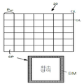
도 1과 같이, 본 발명의 입체 영상 표시 장치는, 복수개의 서브 픽셀을 매트릭스 상으로 갖고, 영상을 표시하는 영상 패널(200), 상기 영상 패널(200) 상측에 위치하며 복수개의 시점(view, 이하 '뷰')으로 영상을 분리하는 패럴랙스부(400) 및 상기 영상 패널의 하면에 위치하여, 상기 서브 픽셀의 일부 영역만을 오픈하는 하면 배리어(300)을 포함한다.1, a stereoscopic image display apparatus according to the present invention includes a
한편, 도면 상의 도시된 광원 유닛(100)은 측면 혹은 하측에 배치된 광원으로부터 광을 상측으로 전달하는 것으로, 광원과 복수개의 광학 쉬트를 포함한다. 그리고, 광원 유닛(100)은 영상 패널(200)의 종류에 따라 생략될 수 있다. 예를 들어, 영상 패널(200)이 유기 발광 표시 패널 혹은 전기 영동 표시 패널과 같은 자발광 소자인 경우에는 상기 광원 유닛(100)은 생략될 수 있으며, 영상 패널(200)이 액정 표시 패널과 같이, 수광형 소자인 경우, 광원 유닛(100)이 구비된다.In the meantime, the
상기 광원 유닛(100)에 이용되는 광원은 형광 램프 어레이, 발광 다이오드(LED: Light Emitting Diode) 어레이, 레이저 광원 어레이 등일 수 있으며, 하측에서 영상 패널(200)로 면발광을 유도하기 위해 도광판 및 확산 쉬트와 같은 복수개의 광학 쉬트를 포함할 수 있다.The light source used in the
또한, 상기 하면 배리어(300)는 규칙적으로 배열된 개구부를 가지며, 상기 개구부는 상기 영상 패널의 서브픽셀의 일부 영역만을 오픈시켜 소정의 뷰(view)에서, 영상패널(200)의 광학적 피치를 줄임으로써, 광학적 피치에 반비례하는 OVD(광학 시청 거리)의 특성상 입체 영상 표시 장치의 광학 시청 거리를 늘릴 수 있게 한다. 여기서, 상기 하면 배리어(300)는 영상 패널(200)로 전달된 서로 다른 뷰의 영상의 일부에 해당하는 광이 영상 패널 상측의 패럴랙스부로 출사되게 한다.In addition, the
또한, 상기 하면 배리어(300)의 종래의 입체 영상 표시 장치에서, 대략 5mm 이상의 두께를 갖는 갭 글래스와 달리, 영상 패널(200)의 하면에 차광 패턴의 패터닝으로 구현이 가능하여, 패터닝된 차광 패턴의 두께는 0.05㎛ 내지 0.3㎛ 수준으로 영상 패널(200)과 패럴랙스부(400)의 합산된 두께에 거의 영향을 주지 않을 수준이다. 따라서, 영상 패널의 상면과 하면에 각각 패럴랙스부와 하면 배리어를 구비하여 슬림화한 상태를 유지하여, 광학 시청 거리를 늘린 입체 영상 표시 장치를 구현할 수 있다.Unlike the gap glass having a thickness of about 5 mm or more in the conventional three-dimensional image display device of the
또한, 상기 패럴랙스부(400)는 예를 들어, 렌티큘러 렌즈 어레이로 세로 방향으로 길게 일정한 피치(PL)를 갖는 렌즈가 규칙적으로 배열되어 있다. 또한, 상기 렌티큘러 렌즈 어레이는 도시된 일정한 곡률을 가진 렌즈의 형태일 수도 있고, 혹은 전압에 의해 온/오프되며 굴절률 변화가 조절되는 스위처블 렌즈 어레이일 수 있다. 스위처블 렌즈 어레이일 경우, 상기 입체 영상 표시 장치는, 스위처블 렌즈 어레이의 온/오프에 의해 선택적으로 3D/2D 표시가 가능하다. 이 경우, 스위처블 렌즈 어레이의 가장 기본적인 형태는 서로 대향된 제 1, 제 2 기판과, 상기 제 1, 제 2 기판 사이의 액정층과, 상기 제 2 기판 상의 공통 전극과, 상기 제 1 기판 상에 일 피치에 해당한 렌즈 영역에 대응하여 복수개 구비된 제 1 전극들을 포함하여 이루어진다.For example, the
스위처블 렌즈 어레이는, 3D 표시일 경우, 렌즈 영역의 중심에 위치한 제 1 전극에 가장 큰 전압을 인가하고, 렌즈 영역의 중심에서 멀어질수록 점차 낮아지는 전압을 인가하고, 제 2 전극에는 제 1 전극들에 인가하는 전압 중 가장 낮은 전압을 인가하여, 구동된다. 이 때, 렌즈 영역의 중심에서 굴절률이 가장 작고 중심에서 멀어질수록 굴절률을 점차 크게 되어, 마치 렌티큘러 렌즈와 같은 광학적 굴절률 차를 얻어, 영상 패널(200)에서 나온 영상이 시점에 따라 분리된다.In the case of 3D display, the switchable lens array applies the highest voltage to the first electrode located at the center of the lens region and applies a gradually lowering voltage toward the center of the lens region, And is driven by applying the lowest voltage among the voltages applied to the electrodes. At this time, the refractive index is the smallest at the center of the lens region and the refractive index gradually increases as the distance from the center increases. Thus, the optical refractive index difference such as the lenticular lens is obtained, and the image from the
또한, 스위처블 렌즈 어레이는, 2D 표시일 경우, 구비된 제 1 전극들 및 공통 전극에 굴절률 차를 없게 하여, 마치 투명 필름처럼 기능하여, 하측 영상 패널의 영상이 그대로 출사된다.Also, in the case of a 2D display, the switchable lens array functions as a transparent film so as to eliminate the refractive index difference between the first electrodes and the common electrode, so that the image of the lower image panel is output as it is.
상기 영상 패널(200)은 투과형 영상 패널과, 수광형 영상 패널로 구분될 수 있으며, 모두 적용 가능하다. 도시된 도 1에는 광원 유닛(100)이 구비된 것으로, 이 경우에는 수광형 영상 패널인 것을 전제로 하나, 광원 유닛(100)을 생략하여, 하면 배리어(300), 영상 패널(200) 및 패럴랙스부(400)의 순으로만 입체 영상 표시 장치를 구현할 수 있다.The
상기 영상 패널(200)은 일 예로 액정 패널, 전기 영동 패널, 양자점 표시 패널, 유기 발광 표시 패널 등일 수 있으며, 예를 들어, 액정 패널일 경우, 서로 대향된 하판 및 상판과, 그 사이에 충진된 액정층, 상기 하판 측에 박막 트랜지스터 어레이, 상판측의 컬러 필터 어레이를 포함한다.The
그리고, 설명하지 않은 부호 251, 252는 영상 패널(200)의 상하에 위치한 제 1 편광판과 제 2 편광판을 나타내는 것으로, 상기 제 1, 제 2 편광판(251, 252)은 서로 교차하는 투과축을 갖는다. 그리고, 상기 제 1, 제 2 편광판(251, 252)은 영상 패널(200)이 액정 패널인 경우로, 전압 무인가의 초기 상태에서 하판과 상판 측의 액정의 배열이 서로 꼬인 상태로, 초기 상태의 광의 투과를 제어하기 위해 구비된다. 제 1, 제 2 편광판(251, 252)은 영상 패널의 종류에 따라 일측 혹은 양측에서 모두 생략될 수도 있다.
한편, 본 발명의 발명자들은 입체 영상 표시 장치에 있어서, 영상 패널의 서브픽셀의 피치와, 하면 배리어의 피치간 관계에 대해 실험을 진행하여 휘도 편차를 최소화한 구조를 제안한다.On the other hand, the inventors of the present invention propose a structure in which the brightness deviation is minimized by conducting experiments on the relationship between the pitch of the subpixels in the image panel and the pitch of the bottom barrier in the stereoscopic image display device.
먼저, 하면 배리어의 개구부 주기를 영상 패널과 동일하게 한 비교예에 대해 설명한다.First, a comparative example in which the aperture period of the lower surface barrier is made the same as that of the image panel will be described.
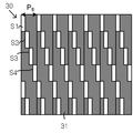
도 2a 내지 도 2c는 비교예에 따른 영상 패널, 하면 배리어 및 패럴랙스부를 나타낸 평면도이다.2A to 2C are plan views showing a video panel, a bottom barrier and a parallax part according to a comparative example.
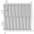
도 2a 내지 도 2c와 같이, 비교예에 따른 입체 영상 표시 장치는 크게 광학적 기능으로 영상 패널(20), 하면 배리어(30) 및 패럴랙스부(40)로 나눌 수 있다.2A to 2C, the stereoscopic image display device according to the comparative example can be roughly divided into an
비교예에서는 4뷰를 나타낸 것으로, 동일한 수평 라인들의 서브 픽셀들에 대해서는 같은 뷰가 표현되고, 수직 방향에서 차례로, 1, 2, 3, 4 뷰가 표현된다. 각각의 뷰는 영상 패널(20)의 각 서브 픽셀에 영상 정보를 주어 나타날 수 있다.In the comparative example, four views are shown. The same view is displayed for subpixels of the same horizontal lines, and 1, 2, 3, and 4 views are displayed sequentially in the vertical direction. Each view may be presented with image information to each subpixel of the
도 2a와 같이, 영상 패널(20)은 서로 교차하는 게이트 라인(GL)과 데이터 라인(DL)에 의해 서브픽셀(SP)이 나뉘며, 게이트 라인(GL)과 데이터 라인(DL)의 교차부에 박막 트랜지스터(미도시)와, 상기 박막 트랜지스터에 연결된 적어된 하나의 화소 전극(미도시)이 서브픽셀 내에 구비된다. 그리고, 상기 서브 픽셀의 경계부에는 상기 게이트 라인(GL)과 데이터 라인(DL)과, 박막 트랜지스터를 커버하는 블랙 매트릭스층(BM)을 더 포함한다. 일반적으로 블랙 매트릭스층(BM)의 폭은 게이트 라인(GL), 데이터 라인(DL)의 폭보다 충분히 크게 하여, 배선이나 소자 형성부를 가린다.2A, in the
그리고, 상기 서브픽셀(SP)은 일정한 가로 피치(PSP)를 갖고, 매트릭스 상으로 배치되어 있다.The subpixels SP have a constant lateral pitch P SP and are arranged in a matrix.
도 2b와 같이, 하면 배리어(30)의 개구부(S1, S2, S3, S4)의 주기(PB)가 도 2a의 영상 패널(20)의 서브 픽셀의 피치(PSP)와 동일한 것으로, 예를 들어, 수평 라인의 서브 픽셀에서 반복되는 제 1 개구부(S1)의 경우, 제 1 개구부(S1)는 각 서브 픽셀의 왼쪽 경계의 동일한 위치에 대응되며, 하나의 제 1 개구부(S1)의 시점부터 다음 제 1 개구부(S1)의 시점까지의 거리가 주기(PB)에 해당한다. 각 개구부의 주기(PB)는 동일한 것으로, 여기서, 수직한 열 방향에서, 제 1 내지 제 4 개구부(S1, S2, S3, S4)가 위치를 달리한 것은, 서로 다른 뷰에 대하여 다른 영상이 공급될 때, 공간적으로 광을 분리하여 일부 광만을 패럴랙스부(40)로 출사시키기 위함이다. 앞서 설명한 바와 같이, 상기 하면 배리어(30)는 갭 글래스와 같이, 영상 패널의 광학 피치를 줄이는 효과를 가지며, 줄어든 광학 피치에 비례하여, 광학 시청 거리는 늘어날 수 있다.The period P B of the
여기서, 상기 하면 배리어(30)는 상기 개구부(S1, S2, S3, S4)를 제외한 영역에 차광 패턴(31)을 구비한다. 또한, 구현하고자 하는 뷰 수에 상당한 개구부의 가로 간격을 합한 수치가 상기 하면 배리어 각각의 개구부의 주기와 같다.Here, the
그리고, 도 2c와 같이, 패럴랙스부의 단위 렌즈의 피치(PL)은 상기 하면 배리어(30)의 개구부의 주기(PB)와 상기 서브 픽셀의 피치 (PSP)와 동일하다.And, as shown in Figure 2c, it is equal to the pitch (P L) of the parallax lens unit is negative period (P B) and the pitch (P SP) of the subpixel of the opening of the
한편, 이러한 비교예에 따른 입체 영상 표시 장치에서, 서브 픽셀(SP)의 경계부는 서로 교차되는 게이트 라인 및 데이터 라인이 구비되고, 이들을 가리기 위해 상기 게이트 라인과 데이터 라인의 폭보다 일정 마진을 더 갖는 블랙 매트릭스층(도 2a의 BM)이 더 구비된다.On the other hand, in the stereoscopic image display device according to this comparative example, the boundaries of the subpixels SP include gate lines and data lines intersecting with each other and have a margin larger than the width of the gate lines and the data lines A black matrix layer (BM in Fig. 2A) is further provided.
그런데, 도 2b와 같이, 제 1 개구부(S1)와 제 4 개구부(S4)는 항상 서브 픽셀에 동일한 부위에 대응되며, 도시된 바와 같이, 서브 픽셀의 가장 자리에 대응되어 블랙 매트릭스층과 중첩 면적이 많은 반면, 제 2 개구부(S2)와 제 3 개구부(S3)는 블랙 매트릭스층과 중첩된 부분이 없다. 동일 수평 라인에 대해서는, 매 서브 픽셀들에 대해 같은 위치에 개구부가 대응되므로, 제 1 개구부가 있는 수평 라인들 및 제 4 개구부가 있는 수평 라인들은 개구부가 블랙 매트릭스층에 거의 가려지고, 제 2, 제 3 개구부가 있는 수평 라인들은 대부분 서브 픽셀의 영역이 오픈되어 영역들간의 광량차가 발생한다. 특히, 이는 표시 상에서 블랙 매트릭스층과 중첩된 면적이 많은 영역이 까맣게 보이는 블랙 밴드(black band) 현상으로 관찰되고, 직접적으로 시청자를 이를 인지하여 시감을 저해시키는 큰 요인이 된다. However, as shown in FIG. 2B, the first opening S1 and the fourth opening S4 always correspond to the same portion in the subpixel, and as shown, the black matrix layer and the overlapping area The second opening S2 and the third opening S3 do not overlap with the black matrix layer. For the same horizontal line, the horizontal lines with the first opening and the horizontal lines with the fourth opening are substantially obscured by the black matrix layer and the second, The horizontal lines having the third openings mostly open the subpixel region, resulting in a light amount difference between the regions. In particular, this is observed as a black band phenomenon in which an area having a large area overlapping with the black matrix layer on the display is black, and this is a major factor for the viewer to directly perceive such a black band phenomenon.
이하의 본 발명의 입체 영상 표시 장치는 상기 블랙 밴드 현상을 방지한 구조를 제안한다.The following three-dimensional image display apparatus of the present invention proposes a structure for preventing the black band phenomenon.
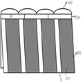
도 3a 및 도 3b는 본 발명의 입체 영상 표시 장치에 있어서, 영상 패널, 하면 배리어, 패럴랙스부의 관계를 나타낸 평면도이다.3A and 3B are plan views showing the relationship between a video panel, a bottom barrier, and a parallax portion in the stereoscopic image display device of the present invention.
본 발명의 입체 영상 표시 장치에 있어서도, 비교예와 같이, 뷰 표현은 수직 방향에서만 다르게 하고, 수평 방향의 서브 픽셀들에 대하여는 동일 뷰를 표현한다.Also in the stereoscopic image display device of the present invention, the view representation is different only in the vertical direction, and the same view is displayed for the subpixels in the horizontal direction, as in the comparative example.
또한, 본 발명의 입체 영상 표시 장치에 있어서, 영상 패널(200)의 서브 픽셀의 배치는 앞서 비교예에서 설명한 바와 동일하게, 매트릭스 상으로 배치되며, 각 서브 픽셀(SP)의 경계부는 서로 교차하는 게이트 라인과 데이터 라인이 배치되고, 매 서브 픽셀(SP)에 대해 상기 게이트 라인과 데이터 라인의 교차부에 박막 트랜지스터(미도시)가 구비되고, 상기 서브 픽셀 내에는 상기 박막 트랜지스터와 전기적으로 연결된 화소 전극(미도시)이 구비되어 있다. 또한, 상기 게이트 라인 및 데이터 라인을 가리도록 블랙 매트릭스층이 구비된다.In the stereoscopic image display apparatus of the present invention, the arrangement of the subpixels of the
상기 영상 패널(200)이 액정 패널일 경우, 수직 전계 모드와 수평 전계 모드에 따라 상기 서브 픽셀의 전극 배치를 달리할 수 있다. 수직 전계 모드일 경우, 상기 서브 픽셀에는 단일의 화소 전극이 일측 기판이 배치되고, 대향 기판측에는 공통 대향 전극이 전체 서브픽셀에 걸쳐 공통적으로 형성된다. 또한, 수평 전계 모드일 경우, 상기 서브 픽셀에는 서로 교번하는 형태의 화소 전극과 공통 전극이 구비된다.When the
도 3a 및 도 3b와 같이, 본 발명의 입체 영상 표시 장치는, 하면 배리어(300)의 개구부(S)의 주기(PB)를 영상 패널의 서브 픽셀의 피치(PSP)와 차이를 갖는 것을 특징으로 한다.3A and 3B, in the stereoscopic image display apparatus of the present invention, the period P B of the opening S of the
도 3a는 상기 하면 배리어(300)의 개구부(S)의 주기(PB)를 서브 픽셀 피치(PSP)보다 작게 한 것이고, 도 3b는 개구부(S)의 주기(PB)를 서브 픽셀 피치(PSP)보다 크게 한 것이다. 이를 통해, 동일한 수평 라인의 서브 픽셀에 대하여 다른 위치에 개구부(S)가 대응될 수 있다. 따라서, 동일한 수평 라인의 서브 픽셀에 동일 뷰가 표시된다면, 동일한 수평 라인의 서브 픽셀들의 다른 위치에서 동일 뷰를 나타낼 수 있게 되고, 동일 뷰에 대응되는 개구부와 서브 픽셀의 블랙 매트릭스층에 대한 중첩이 특정 부분에 치우지지 않게 되고 평균 값을 가질 수 있게 된다. 따라서, 동일한 뷰에 대하여 휘도의 편차를 방지할 수 있다.3A shows the period P B of the opening S of the
도 3a를 참조하며, 도시된 3개의 서브 픽셀 중 가장 좌측의 서브 픽셀에서는 좌우 경계부에 첫번째, 두번째 개구부(S)가 구비되어 블랙 매트릭스층(BM)과 개구부(S)의 중첩이 크지만, 중앙 서브 픽셀과 가장 우측 서브 픽셀은 세번째, 네번째 개구부가 서브 픽셀의 중심에 가깝게 위치하여, 블랙 매트릭스층(BM)과 개구부간의 중첩 면적이 작다. 이 경우, 동일 뷰에 대한 수평 라인의 서브픽셀들(SP)과 상이한 위치의 개구부(S)의 대응으로, 세번째, 네번째 개구부가 첫번째, 두번째 개구부를 보상하는 효과를 갖는다. 예를 들어, 첫번째, 두번째 개구부가 서브 픽셀의 블랙 매트릭스층(BM)과 갖는 중첩 면적이 각 개구부의 75%, 50%라 하고, 세번째, 네번째 개구부가 서브 픽셀의 블랙 매트릭스층과 갖는 중첩 면적의 각 개구부의 15%라 하고 평균적으로, 해당 뷰에서 서브 픽셀들의 블랙 매트릭스층은 개구부에 대해 38.75%의 중첩된 결과를 얻게 되고, 이 경우, 평균적으로 동일 뷰의 수평 라인에 대해 각 개구부의 나머지 61.25%의 면적에서 서브 픽셀의 화소 영역과 대응되어 광이 투과된다.3A, in the leftmost subpixel among the three subpixels, the first and second openings S are provided at the left and right boundaries, so that the superposition of the black matrix layer BM and the opening S is large, The third and fourth openings of the subpixel and the rightmost subpixel are positioned close to the center of the subpixel so that the overlapping area between the black matrix layer BM and the opening is small. In this case, the third and fourth openings have the effect of compensating the first and second openings in correspondence of the openings S at different positions from the sub-pixels SP of the horizontal line for the same view. For example, the overlap area of the first and second openings with the black matrix layer (BM) of the subpixel is 75% and 50% of each aperture, and the third and fourth openings are overlapped with the black matrix layer On average, at 15% of each of the openings, the black matrix layer of subpixels in the view results in an overlap of 38.75% for the openings, in which case the average of the remaining 61.25 And the light is transmitted in correspondence with the pixel region of the subpixel in the area of%.
이와 같이, 본 발명의 입체 영상 표시 장치는, 각 수평 라인의 서브 픽셀에 대해 서브 픽셀의 블랙 매트릭스층과 개구부의 중첩 관계가 평균화되어 다른 뷰들의 수평 라인들간 나타나는 휘도 불균일이 방지될 수 있다.As described above, in the stereoscopic image display apparatus of the present invention, the overlapping relationship between the black matrix layer of the subpixel and the opening portion is averaged with respect to the subpixels of the respective horizontal lines, thereby preventing luminance unevenness between horizontal lines of different views.
또한, 영상 패널은 자체적으로 화소 영역을 정의하는 블랙 매트릭스층을 포함하는데, 차광성의 블랙 매트릭스층이 하면 배리어의 개구부 영역과 중첩되었을 때, 투과되는 광량이 줄어든다. 특히, 도 2a와 같이, 영상 패널의 서브 픽셀 피치와 하면 배리어의 개구부 주기를 동일하게 할 경우, 특정 수평 라인에서 하면 배리어의 개구부와 블랙 매트릭스층의 중첩 정도가 심하여, 이로 인한 수평 라인들간의 휘도 편차가 심하다. 본 발명의 입체 영상 표시 장치는, 하면 배리어(300)의 개구부(S)를 동일 뷰에 수평 라인의 서브 픽셀에 대하여 배치시 배리어의 개구부 위치를 각 서브 픽셀에 대해 서로 다른 위치에 대응되도록 하여, 서브 픽셀의 블랙 매트릭스층과 하면 배리어의 차광 패턴의 중첩 면적이 큰 부위가 집중되어 발생되는 블랙 밴드 현상을 방지할 수 있다.Further, the image panel includes a black matrix layer that defines a pixel region by itself, and the amount of light transmitted when the black matrix layer of light blocking property overlaps the opening area of the bottom surface of the barrier is reduced. In particular, when the subpixel pitch of the image panel and the opening period of the lower barrier are the same, as shown in FIG. 2A, the degree of overlap between the opening portion of the lower barrier and the black matrix layer in a specific horizontal line is large, Deviation is severe. In the stereoscopic image display device of the present invention, when the openings S of the
그리고, 동일 뷰가 공급되는 서브 픽셀들에 대하여 개구부의 위치를 달리한 것으로, 동일한 수평 라인의 개구부가 서로 다른 서브 픽셀과 중첩되더라도 개구부에서는 동일 뷰가 나타나기에, 3D 크로스토크(다른 뷰의 영상이 간섭되어 나타나는 현상)도 방지할 수 있다.Even if the openings of the same horizontal line are overlapped with different subpixels, the same view is displayed in the openings, so that the 3D crosstalk (the image of the other view) Interference phenomenon) can be prevented.
한편, 상기 하면 배리어(300)의 개구부(S)가 아닌 영역에는 하부에서 입사되는 광을 차단하는 차광 기능의 차광 패턴(310)을 갖는다.On the other hand, the
여기서, 상기 개구부(S)의 주기는, 수평 라인의 서브 픽셀에 대해 하나의 개구부(S)의 시점부터 다음 개구부(S)의 시점 사이의 가로 간격을 의미한다. 구현하고자 하는 뷰가 4 view 일 때(도 2b 참조), 수직 방향으로 서로 다른 뷰가 배치되며, 수직 방향에서, 각 개구부는 전단 수평 라인의 개구부에 대해 각 개구부의 가로 폭만큼 쉬프트된 위치에 배치된다. 이는 다른 뷰에 대해 다른 영상이 공급될 때, 공간적으로 광을 분리하여 일부 광만을 패럴랙스부(400)로 출사시키기 위함이다. 앞서 설명한 바와 같이, 상기 하면 배리어(300)는 갭 글래스와 같이, 영상 패널의 광학 피치를 줄이는 효과를 가지며, 줄어든 광학 피치에 비례하여, 광학 시청 거리는 늘어날 수 있다. 특히, 상기 개구부의 주기를 상기 서브 픽셀의 피치보다 작게할 때, 개구부의 주기(PB)를 뷰 수로 나눈 값(PB/ view 수)이 상기 개구부의 가로 폭에 상당하다. 상기 개구부의 가로 폭이 줄수록 상기 영상 패널(200)의 광학 피치가 줄어드는 효과를 가져 이를 통해 광학 시청 거리를 더 늘릴 수 있다.Here, the period of the opening S means a horizontal interval between the start of one opening S and the start of the next opening S with respect to the subpixel of the horizontal line. When the view to be implemented is 4 views (see FIG. 2B), different views are arranged in the vertical direction, and in the vertical direction, each opening is arranged at a position shifted by the width of each opening relative to the opening of the front- do. This is for separating the light spatially and outputting only a part of light to the
도시된 예는 4뷰에 관한 것이나, 이에 한하지 않고, 3D 입체 표시 가능한 2 뷰 이상이라면 모두 적용 가능하다. The illustrated example relates to four views, but the present invention is not limited to this, and any two or more views capable of 3D stereoscopic display are applicable.
한편, 상기 하면 배리어(300)의 주기와 패럴랙스부(400)의 렌즈 피치는 거의 동등하다. 경우에 따라, 하면 배리어(300)의 주기 대비 상기 패럴랙스부(400)의 렌즈 피치를 약간 작게 할 수도 있다.On the other hand, the period of the
도 3b는 하면 배리어(300)의 주기가 서브 픽셀의 피치보다 큰 것으로, 이 경우에는, 모든 하면 배리어(300)의 개구부는 서로 다른 위치의 서브 픽셀의 부위에 대응된다. 경우에 따라, 개구부가 대응되지 않는 서브 픽셀의 위치도 있을 것이다.3B shows that the period of the
이 경우, 상기 개구부의 주기를 상기 서브 픽셀의 피치보다 큰 경우, 개구부의 주기(PB)를 뷰 수로 나눈 값(PB/ view 수)에 상당한 상기 개구부의 가로 폭은 비교예나 도 3a의 경우 대비 늘어나게 되어, 이 때 상기 영상 패널(200)의 광학 피치가 늘어난 효과를 가져 이를 통해 광학 시청 거리를 줄일 수도 있다.In this case, when the period of the opening portion is larger than the pitch of the sub-pixels, the width of the opening portion corresponding to the value (P B / number of views) obtained by dividing the period (P B ) So that the optical pitch of the
즉, 본 발명의 입체 영상 표시 장치는, 서브 픽셀의 피치와 하면 배리어의 각 개구부의 주기를 달리하되, 달라진 개구부의 주기로 적정 시청 거리를 확보할 수 있다. 예를 들어, 도 3b와 같이, 서브 픽셀의 피치보다 하면 배리어의 각 개구부의 주기를 크게 하면, 광학 시청 거리를 줄일 수 있고, 도 3a와 같이, 서브 픽셀의 피치보다 하면 배리어의 각 개구부의 주기를 작게 하면, 광학 시청 거리를 늘릴 수 있다.That is, in the stereoscopic image display apparatus of the present invention, it is possible to secure a proper viewing distance at a period of the changed opening by varying the pitch of subpixels and the period of each opening portion of the lower barrier. For example, as shown in FIG. 3B, if the period of each opening portion of the lower barrier is made larger than the pitch of the subpixel, the optical viewing distance can be reduced. As shown in FIG. 3A, It is possible to increase the optical viewing distance.
또한, 도 3b에 따른 본 발명의 입체 영상 표시 장치는, 도 3a와 비교하여, 개구부의 주기가 서브 픽셀의 피치보다 늘어난 점 외에는 도 3a와 동일한 조건을 갖는 것으로, 각 수평 라인의 서브 픽셀에 대해 서브 픽셀의 블랙 매트릭스층과 개구부의 중첩 관계가 평균화되어 다른 뷰들의 수평 라인들간 나타나는 휘도 불균일이 방지될 수 있다. 그리고, 동일 뷰가 공급되는 서브 픽셀들에 대하여 개구부의 위치를 달리한 것으로, 동일한 수평 라인의 개구부가 서로 다른 서브 픽셀과 중첩되더라도 개구부에서는 동일 뷰가 나타나기에, 3D 크로스토크(다른 뷰의 영상이 간섭되어 나타나는 현상)도 방지할 수 있다.3A, the three-dimensional image display apparatus according to the present invention has the same conditions as those of FIG. 3A except that the period of the openings is larger than the pitch of the subpixels. The overlapping relationship of the black matrix layer of the subpixel and the opening portion is averaged to prevent luminance unevenness appearing between horizontal lines of different views. Even if the openings of the same horizontal line are overlapped with different subpixels, the same view is displayed in the openings, so that the 3D crosstalk (the image of the other view) Interference phenomenon) can be prevented.
한편, 상기 서브픽셀(SP)은 실질적으로 전계 구동시 영상이 투과되는 화소 영역과, 차광 패턴이 형성된 차광 영역으로 구분될 수 있다.Meanwhile, the sub-pixel SP may be divided into a pixel region through which an image is transmitted at the time of electric field driving and a light-shielding region formed with a light-shielding pattern.
본 발명의 입체 영상 표시 장치에서는, 하면 배리어(300)의 피치와 상기 서브 픽셀의 피치가 동일하지 않게 때문에, 도 3a 및 도 3b와 같은 설계시 개구부는 수평 라인에서, 서브 픽셀의 동일한 위치에 있지 않다.In the stereoscopic image display apparatus of the present invention, since the pitch of the sub-pixels 300 is not equal to the pitch of the sub-pixels, the openings at the time of design as shown in Figs. 3A and 3B are not located at the same position not.
한편, 본 발명의 입체 영상 표시 장치와 같은 설계에서도 상기 하면 배리어(300)의 각 개구부의 주기와 상기 영상 패널의 서브 픽셀의 피치의 최소 공배수에 해당하는 피치로, 규칙성이 생기는데, 예를 들어, 하면 배리어(300)의 개구부의 주기를 300㎛로 하고, 서브 픽셀의 피치를 400㎛로 할 때, 1200㎛의 피치 간격으로 규칙성을 갖게 된다.On the other hand, even in the same design of the stereoscopic image display apparatus of the present invention, regularity occurs at a pitch corresponding to the least common multiple of the pitch of the subpixels of the image panel and the period of each opening of the
한편, 상기 하면 배리어의 개구부는 도 3a 및 도 3b와 같은 직사각형의 형상도 가능하지만, 하기와 같은 변형예도 가능하다.3A and 3B. However, the following modifications are also possible.
도 4a 내지 도 4c는 본 발명의 입체 영상 표시 장치의 하면 배리어의 개구부를 여러 형태로 나타낸 평면도이다.4A to 4C are plan views showing various forms of openings of a bottom barrier of the stereoscopic image display device of the present invention.
도 4a는 하면 배리어(300)의 개구부를 사선 방향으로 기울인 형태로 갖는 것으로, 일종의 평행 사변형의 형태로 개구부(S)가 형성됨을 나타낸다. 그리고, 수평 라인의 서브 픽셀들에 대해, 개구부(S)와 개구부(S) 사이에는 개구부(S)와 동일하거나 가로 폭이 다른 평행 사변형의 차광 패턴(310)이 구비된다. 예를 들어, 2 뷰일 경우에는, 수평 라인들에 대해 개구부(S)와 차광 패턴(310)의 면적 비는 1:1이며, 3뷰일 경우, 개구부(S)와 차광 패턴(310)의 면적 비는 1:2, n (자연수) 뷰일 경우, 개구부와 차광 패턴의 면적 비는 1: (n-1)의 관계에 있다.FIG. 4A shows that the opening S of the
한편, 서로 다른 수평 라인들의 서브 픽셀(SP)의 경계에는, 수평 방향으로, 차광 패턴(310, 도 5 참조)을 더 구비할 수 있다.On the other hand, the light-shielding pattern 310 (see FIG. 5) may be further provided in the horizontal direction at the boundary of the subpixels SP of the different horizontal lines.
이 경우, 상기 개구부(S)가 갖는 기울기와 동일하게 영상 패널(200)의 상측에 위치하는 패럴랙스부(400)는 렌즈 형태로 사선의 기울기를 가질 수 있다.In this case, the
도 4b는 하면 배리어(300)의 개구부(S) 형상을 마름모꼴로 한 것으로, 이 경우에는 마름모꼴의 개구부(S)를 제외한 영역에 차광 패턴(310)이 구비된다.4B is a cross-sectional view of the
도 4c는 하면 배리어(300)의 개구부(S) 형상을 각각 중심을 경계로 상하에서 다른 방향으로 기울어진 평행 사변형이 접합된 형태로 할 수도 있다.4C, the shape of the openings S of the
이러한 개구부(S)의 형상은 영상 패널의 각 서브 픽셀이 갖는 화소 영역(블랙 매트릭스층을 제외한 영역)의 형상일 경우, 이와 동일하게 하거나 개구부의 가로 폭만을 조절하여 따를 수도 있고, 혹은 서브 픽셀의 형상과 무관하게 가질 수도 있다.The shape of the opening S may be the same as the shape of the pixel region (region excluding the black matrix layer) of each subpixel of the image panel or may be controlled by adjusting only the width of the opening portion, It may be independent of shape.
한편, 도 4a 내지 도 4c의 경우, 상기 개구부가 갖는 기울기에 따라 패럴랙스부(400)의 렌즈 영역이 구비된다. 즉, 하면 배리어가 갖는 개구부의 슬랜티드 각도(slanted angle)와 패럴랙스부(400)의 렌즈 영역의 슬랜티드 각도는 동일하다.4A to 4C, the lens region of the
도 5는 본 발명의 입체 영상 표시 장치를 4뷰로 구현시 일예에 따른 평면도이며, 도 6a 및 도 6b는 도 5의 영상 패널과 하면 배리어를 각각 나타낸 평면도이고, 도 7은 도 5의 I~I' 선상의 단면도이다.FIG. 5 is a plan view of a stereoscopic image display device according to an embodiment of the present invention. FIG. 6A and FIG. 6B are plan views showing the image panel and the bottom barrier of FIG. &Quot;
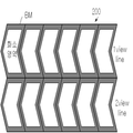
도 5 내지 도 7과 같이, 본 발명의 입체 영상 표시 장치는, 각 서브 픽셀(SP)의 화소 영역이 중심을 경계로 상하에서 다른 방향으로 기울어진 평행 사변형이 접합된 형태인 것을 나타낸다.5 to 7, the stereoscopic image display device of the present invention shows that a pixel region of each subpixel SP has a parallelogram shape in which the center of the subpixel SP is tilted in different directions from upper and lower sides.
영상 패널(200)은 서로 대향된 하판(210)과 상판(220), 상기 하판(210)과 상판(220) 사이의 액정층(240)과, 상기 하판(210) 상의 박막 트랜지스터 어레이 (미도시), 상기 상판(220) 상의 블랙 매트릭스층(BM) 및 컬러 필터층(CF)를 포함한 컬러 필터 어레이를 갖는다.The
상기 영상 패널(200)의 화소 영역에 구비된 전극의 형태로, 크게 IPS(In-Plane Switching) 모드와 TN (Twisted Nematic) 모드로 구별할 수 있으며, 전자의 경우, 동일한 기판 상의 각 화소 영역에 화소 전극과 공통 전극이 서로 교번되어 배치되어, 각 전극에 전압 인가시 수평 전계로 구동되며, 후자의 경우는 서로 다른 기판 상의 각 화소 영역에 화소 전극과, 대향 공통 전극이 구비되어, 각 전극에 전압 인가시 수직 전계로 구동된다. 후자의 경우, 대향 공통 전극은 대향 기판측에 전 화소 영역에 걸쳐 공통 전극으로 형성되어 있다.(IPS) mode and a twisted nematic (TN) mode in the form of electrodes provided in the pixel region of the
일반적으로 IPS 모드인 경우, 도시된 지그재그 형태의 화소 영역의 형상을 가지나, TN 모드의 경우에도 이러한 형상을 가질 수 있다.Generally, in the case of the IPS mode, it has the shape of the zigzagged pixel region shown, but it can also have this shape in the case of the TN mode.
첫번째 수평 라인과, 두번째 수평 라인의 서브 픽셀은 각각 1 뷰와, 2 뷰를 나타낸다. 도시하지 않았지만, 세번째, 네번째 수평 라인의 서브 픽셀을 3뷰와 4뷰를 나타낼 것이며, 이후의 수평 라인들에 대해서는 차례대로, 1뷰 내지 4뷰가 반복된다.The first horizontal line and the second horizontal line subpixels represent one view and two views, respectively. Although not shown, the subpixels of the third and fourth horizontal lines will represent three views and four views, and one or four views are repeated for the subsequent horizontal lines in turn.
그리고, 하면 배리어(300)와 패럴랙스부(400)는 서브 픽셀에 대해 일정한 기울기를 갖고 기울어져 있다. 여기서, 하면 배리어(300)의 개구부(S)가 갖는 기울기와 패럴랙스부(400)가 갖는 기울기는 동일하다.Then, the
본 발명의 입체 영상 표시 장치는 하면 배리어(300)의 개구부(S)가 갖는 주기(PB)를 상기 영상 패널(200)의 서브 픽셀(SP)의 피치(PSP)와 다르게 한 것으로, 동일한 수평 라인의 서브 픽셀에 대해 매 서브 픽셀의 다른 위치에 하면 배리어의 개구부가 대응된다. 그리고, 개구부(S)가 위치하지 않은 상기 하면 배리어(300)에는 차광 패턴(310)이 구비된다.The stereoscopic image display apparatus of the present invention has the period P B of the opening S of the
상기 하면 배리어(300)는 수평 라인의 서브 픽셀들에 대해 개구부(S)와 차광 패턴(310)을 한 세트로 한 배리어 블록이 반복된다.The
그리고, 상기 하면 배리어(300)의 개구부(S)는 수직 방향에서 개구부(S) 폭만큼 쉬프트되어, 다른 뷰에 대한 광 투과 영역을 정의한다.The opening S of the
이 경우, 4뷰를 구현시, 4개의 수평 라인마다 동일 뷰가 반복된다. 이 때, 상기 하면 배리어(300)의 개구부(S)가 서브 픽셀(SP)에 대응되어 기울어져 있고, 각 서브 픽셀(SP)들은 수평 라인들이 서로 쉬프트되어 있지 않고, 수직 방향에서 서브 픽셀들이 동일한 위치에 있기 때문에, 동일 뷰라 하더라도, 첫번째 수평 라인과 다섯번째 수평 라인에서의 개구부는 각 서브 픽셀의 다른 위치에 대응될 수 있다. 즉, 수직 방향에서 기울어진 하면 배리어의 개구부는 동일 뷰에 대해 서로 다른 위치의 서브 픽셀에 대응되고, 수직 방향에서도 서브 픽셀에 대해 서브 픽셀의 블랙 매트릭스층과 개구부의 중첩 관계가 평균화되어 다른 뷰들의 수평 라인들간 나타나는 휘도 불균일이 방지될 수 있다.In this case, when four views are implemented, the same view is repeated for every four horizontal lines. At this time, the opening S of the
한편, 영상 패널(200)의 상측과 하면 배리어(300)의 하측에는 앞서 도 1에서 설명한 제 1, 제 2 편광판(251, 252)이 구비된다.On the other hand, the first and second
제 1 편광판(251) 상측에 구비된 패럴랙스부(400)는 도 1에 도시된 바와 같이, 물리적 굴곡을 갖는 렌티큘러 렌즈 또는 도 7에 도시한 형태의 패널의 형태로도 구비될 수 있다. 도 7의 경우, 상기 패럴랙스 부(400)는 전압 인가에 의해 선택적으로 2D, 3D의 구동을 할 수 있다.The
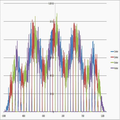
도 8a 및 도 8b는 비교예와 본 발명의 입체 영상 표시 장치의 영역별 휘도 편차를 나타낸 그래프이다.8A and 8B are graphs showing brightness deviations of the three-dimensional image display apparatus according to the comparative example and the present invention.
도 8a는 비교예의 영역별 휘도 편차를 나타낸 것으로, 광학 시청 거리에서, 중심과 좌우 외곽 사이를 관찰할 때 얻어지는 휘도를 나타낸 것으로, 휘도 값에 대한 그래프의 형상이 뚜렷한 고점과 저점이 반복된 형태를 가짐을 알 수 있다. 이는 시청자가 저점이 위치한 영역에서 주위와 다른 심한 휘도 편차로 이 부위에서 블랙 밴드를 인지할 확률이 큼을 예상할 수 있다. 또한, 외곽 영역에서는 거의 휘도 값이 0에 가까운 것으로, 외곽 영역에서는, 3D 인지가 거의 어려움을 예상할 수 있다.FIG. 8A shows luminance deviations for each region in the comparative example. In FIG. 8A, the luminance obtained when observing between the center and the right and left outlines in the optical viewing distance is shown. The shape of the graph with respect to the luminance value is repeated, . It can be expected that the viewer has a high probability of recognizing the black band in the region where the low point is located due to a severe luminance deviation from the surroundings. In addition, it can be expected that the luminance value is almost close to 0 in the outer region, and it is hardly expected to be 3D in the outer region.
도 8b는 도 5와 같은 예로, 실험시 광학 시청 거리에서 중심과 좌우 외곽 사이를 관찰할 때 얻어지는 휘도를 나타낸 것으로, 휘도 값에 대한 그래프의 형상이 뚜렷한 영역별 차이가 거의 없는 점을 관찰할 수 있다. 이는 시청자가 휘도 편차를 거의 느끼지 않고, 안정적으로 3D를 시청할 수 있음을 의미한다. 또한, 외곽 영역에서도 중심과 유사한 고른 휘도 값을 유지하는 것으로, 영역별로 차이없이 고르게 3D를 시청할 수 있음을 나타낸다.FIG. 8B shows the luminance obtained when observing between the center and the right and left outlines in the optical viewing distance in the experiment as shown in FIG. 5. It can be seen that there is almost no difference in the shape of the graph with respect to the luminance value have. This means that the viewer can view the 3D in a stable manner with little feeling of luminance variation. In addition, it maintains a uniform luminance value similar to the center even in the outer area, indicating that 3D can be viewed evenly regardless of the area.
표 1은 상술한 도 8a 및 도 8b를 실험한 비교예와 본 발명의 실험예의 영상 패널, 뷰 맵, 하면 배리어, 패럴랙스 뷰의 조건을 나타낸다.Table 1 shows conditions of a video panel, a view map, a bottom barrier, and a parallax view in the comparative example in which the above-described FIG. 8A and FIG. 8B are tested and the experimental example of the present invention.
도 8a의 비교예와 도 8b의 본 발명의 실시예에서는, 영상 패널은 동일한 크기의 서브 픽셀을 구비하며, 동일한 해상도 및 크기를 갖는 형태로 준비하였으며, 뷰 맵은 공통적으로 4뷰로 적용하고, 수평 라인에는 공통적으로 동일한 뷰가 대응되며, 뷰의 변화는 수직 방향으로만 주었다.In the comparative example of FIG. 8A and the embodiment of FIG. 8B, the image panel has subpixels of the same size and has the same resolution and size. The viewmap is commonly applied to four views, The lines commonly correspond to the same view, and the view changes only in the vertical direction.
여기서, 비교예와, 본 발명의 실시예에서는 하면 배리어의 개구부의 형태를 각각 직사각형과 평행사변형으로 달리하고, 개구부의 폭을 각각 23.xx ㎛와 17.xx ㎛ 로 달리하였다. 앞서 개구부의 폭은 개구부의 주기를 뷰 수를 나눈 값인 점을 설명하였다. 즉, 비교예는, 93.xx ㎛/4 인 것으로, 23.xx ㎛에 상당하며, 본 발명의 실시예는, 개구부 주기를 약 70㎛ 로 한 것으로, 개구부의 폭은 70㎛/4 에 상당한다. 한편, 비교예와, 실험예의 영상 패널의 서브 픽셀 피치는 하나의 예시인 것으로, 그 폭은 변화할 수 있다. 다만, 본 발명과 비교예에서 상이한 것은 본 발명은 영상 패널의 서브 픽셀의 피치와 개구부의 주기를 달리하는 것이다.Here, in the comparative example and the embodiment of the present invention, the shape of the opening of the lower surface barrier was changed to a rectangular parallelogram shape, and the width of the opening was changed to 23.xx m and 17.xx m, respectively. The width of the opening was previously described as the period of the opening divided by the number of views. That is, the comparative example has a size of 93.xx mu m / 4 and corresponds to 23.xx mu m. In the embodiment of the present invention, the opening period is about 70 mu m, and the width of the opening is 70 mu m / 4 do. On the other hand, the subpixel pitches of the comparative example and the experimental panel are one example, and the width thereof can be changed. However, the present invention differs from the comparative example in that the pitch of the sub-pixels of the image panel is different from the period of the opening of the image panel.
또한, 본 발명의 실시예는 비교예와 달리, 0.01˚로 패럴랙스부(400)와 하면 배리어(300)의 개구부에 기울기를 준 것으로, 이는 앞서 설명한 바와 같이, 상하로 위치하는 동일 뷰들의 서브 픽셀들에 다른 위치에 개구부가 대응되어 수직 방향에서의 휘도 불균일을 해결하고자 한다.The embodiment of the present invention differs from the comparative example in that the
한편, 패럴랙스부(400)의 렌즈 피치(PL)는 비교예와 본 발명의 실시예 모두에서, 개구부의 주기보다 약간 작지만 이는 공차이며, 패럴랙스 부(400)의 렌즈 피치와 개구부의 주기는 거의 동등하게 설정한다.On the other hand, the lens pitch P L of the
도 8b는 본 발명의 실시예 적용시 휘도 편차가 영역별로 거의 발생하지 않음을 확인할 수 있으며, 표 1의 광학 시청 거리(OVD)는 비교예 대비 본 발명의 실시예에서 약 1m 늘어난 것으로, 하면 배리어(300)의 개구부의 면적을 줄이지 않더라도, 이러한 광학 시청 거리의 연장 효과가 가능함을 알 수 있다.FIG. 8B shows that the luminance deviation is hardly generated in each region when the embodiment of the present invention is applied, and the optical viewing distance OVD in Table 1 is increased by about 1 m in the embodiment of the present invention, It is possible to extend the optical viewing distance without reducing the area of the opening of the
즉, 본 발명의 실시예에서, 비록 하면 배리어의 단일 개구부 폭은 줄지만 하면 배리어의 개구부가 차지하는 면적은 하면 배리어 면적을 뷰 수로 나눈 것에 상당하여, 실험된 예에서는 4 뷰를 적용하였으므로, 하면 배리어 면적의 1/4에 상당한 것으로, 이는 비교예와 동일한 것으로, 입체 영상 표시 장치의 전체 휘도 특성의 저하도 없게 된다.That is, in the embodiment of the present invention, since the area occupied by the opening of the barrier corresponds to the area of the lower barrier divided by the number of views, if the single opening width of the lower barrier is reduced, This is equivalent to 1/4 of the area, which is the same as that in the comparative example, and the entire luminance characteristic of the stereoscopic image display device is not reduced.
도 9는 본 발명의 입체 영상 표시 장치의 패럴랙스부의 변형예를 나타낸 단면도이다.9 is a sectional view showing a modification of the parallax portion of the stereoscopic image display device of the present invention.
한편, 도 9는 상기 패럴랙스부를 전압 인가 여부에 따라, 3D 표시와 2D 표시로 선택적으로 이용하도록 구성한 것으로, 단위 렌즈 영역에 상당한 부분의 단면도이다.On the other hand, FIG. 9 is a cross-sectional view of a substantial portion of the unit lens region, which is configured to selectively use the parallax portion in 3D display and 2D display depending on whether a voltage is applied or not.
즉, 도 9와 같이, 상기 패럴랙스부는, 서로 대향된 제 1, 제 2 기판(410, 420)과, 상기 제 1, 제 2 기판 사이의 액정층(430)과, 상기 제 1 기판(410) 상에 상기 렌즈 영역에 구비된 복수개의 제 1 전극(411) 및 상기 제 2 기판(420) 상의 제 2 전극(421)을 포함하여 이루어진다.9, the parallax unit includes first and
또한, 상기 제 1 전극(411)을 포함한 상기 제 1 기판(410) 상에 제 1 배향막(431)과, 제 2 전극(421)을 포함한 제 2 기판(420) 상에 제 2 배향막(432)이 더 구비되어, 패럴랙스부(400)의 초기 배향을 제어할 수 있다.A
한편, 상기 제 1 전극(411)과 제 2 전극(421)은 각각 전압원(450)과 연결되어, 전압을 인가받을 수 있다. 상기 제 1 전극(411)은 상기 하면 배리어(도 5의 300 참조)의 개구부(S)가 갖는 기울기를 따르는 것으로, 렌즈 영역(L)에 대응하여, 복수개로 분할되어, 상기 하면 배리어(300)의 개구부(S)의 길이 방향으로 길게 형성되며, 일단 혹은 양단에 패드 전극(미도시)을 마련하여 상기 전압원(450)과 연결된다.The
이 경우, 상기 제 1 전극(411) 및 제 2 전극(421)에 인가되는 전압 여부에 따라 3D 표시와 2D 표시로 구분될 수 있다. 상기 3D 표시에서, 상기 렌즈 영역의 중심으로부터 가장자리에 위치한 상기 제 1 전극들(411)에 대해 점차 증가하거나 점차 낮아지는 전압을 인가하며, 상기 제 2 전극(421)에 상기 제 1 전극(411)에 인가하는 가장 낮은 전압을 인가할 수 있다. 이로써, 상기 패럴랙스부(400)는 각 렌즈 영역에서, 중심에서 가장자리로 가면 점차적으로 굴절률이 변화하게 되어, 광학적으로 렌티큘러 렌즈와 동일 효과를 갖는다.In this case, the display may be divided into a 3D display and a 2D display depending on whether a voltage is applied to the
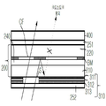
한편, 본 발명의 입체 영상 표시 장치에 있어서, 하면 배리어를 단면 상에서 관찰하면, 도 7과 같이, 하면 배리어(300)는, 개구부(S)를 제외하여 단일층의 차광 패턴(310)이 영상 패널(200)의 하측 배면에 패터닝될 수 있다.7, the
이 경우, 영상 패널이 수광형 소자일 경우, 광원 유닛이 있는 하측에서 광이 상기 하면 배리어의 개구부를 통해 입사되는데, 이 경우, 입사된 광이 영상 패널이 갖는 블랙 매트릭스층(BM)에서 반사되고 하면 배리어의 차광 패턴(310)으로 광 경로를 꺽어 들어와 다시 차광 패턴에서 재반사되어 영상 패널 외측으로 출사되는 경우가 있다. 이 경우, 블랙 매트릭스층(BM), 차광 패턴(310)을 거쳐 재반사된 광은 의도하지 않는 데이터가 될 수 있으며, 이는 3D 크로스토크를 유발할 수 있다.In this case, when the image panel is a light-receiving device, the light is incident on the lower side with the light source unit through the opening of the barrier. In this case, the incident light is reflected on the black matrix layer BM of the image panel The light path is cut off by the
이하, 본 발명의 입체 영상 표시 장치의 하면 배리어의 변형예를 통해 상기 3D 크로스토크를 방지함을 설명한다.Hereinafter, the 3D crosstalk is prevented through the modification of the bottom barrier of the stereoscopic image display device of the present invention.
도 10은 본 발명의 입체 영상 표시 장치의 하면 배리어의 변형예를 나타낸 단면도이다. 도 10은 도 5의 I~I' 선상을 지나는 것이다.10 is a cross-sectional view showing a modification of the bottom barrier of the stereoscopic image display device of the present invention. FIG. 10 is a view that passes through lines I to I 'of FIG.
도 10은 블랙 매트릭스층(BM)과 차광 패턴(310)의 반사 특성으로 인해 나타나는 3D 크로스토크를 방지한 것으로, 상기 차광 패턴(310)의 물질을 변경하여, 블랙 매트릭스층(BM)에서 반사되어 차광 패턴으로 들어오는 광을 소멸시키는 것을 특징으로 한다.10 is a view for preventing the 3D crosstalk caused by the reflection characteristics of the black matrix layer BM and the
예를 들어, 상기 하면 배리어는 상기 개구부를 제외한 영역에, 서로 굴절률이 다른 복수층의 차광 패턴(311, 312, 313)을 가질 수 있다. 도시된 예에서는 삼중층을 도시하였으나, 이중층으로 상기 차광 패턴에서 간섭 광을 소멸시킬 수 있다면 이러한 적용도 가능하다. 이 경우, 상기 차광 패턴(310)의 복수층에, 상기 블랙 매트릭스(BM)에서 상기 차광 패턴측으로 반사시킨 광을 소멸시키는 물질층을 포함할 수 있다. 일예로서, 상기 삼중층은 MoTi/ ITO/MoTi 일 수도 있다. 그러나, 이에 한하지 않고, 이용 가능한 물질층은 반사광의 소멸 간섭을 유도할 수 있는 구조라면 대체 가능할 것이다.For example, the barrier may have a plurality of light-shielding patterns 311, 312, and 313 having different refractive indices from each other in an area excluding the opening. Although a triple layer is shown in the illustrated example, the present invention is also applicable if the double layer is capable of eliminating the interference light in the light shielding pattern. In this case, a plurality of layers of the light-
도시된 예는, 상기 차광 패턴(310)은 제 1 굴절률의 제 1 차광 금속층(311), 상기 제 1 차광 금속층(311) 상에 제 2 굴절률의 투명 금속층(312) 및 상기 투명 금속층(312) 상의 상기 제 1 굴절률의 제 2 차광 금속층(313)으로 이루어진 예를 나타낸 것이다. 이 때, 차광 패턴(310)은 이루는 3층의 물질층은 서로 인접한 계면에서 다른 굴절률을 가지므로, 계면에서 굴절되어 나가는데, 앞서 제 1 차광 금속층(311)의 표면에서 굴절된 광에 대해 투명 금속층(312) 및 제 2 차광 금속층(313)의 표면에서 굴절된 광들이 소멸 간섭 작용을 하여, 최종적으로 상측의 화소 영역을 통과하는 광량을 줄이거나 방지하여, 3D 크로스토크를 방지한 것이다.In the illustrated example, the light-
실제 도 10의 컬러 필터층(CF) 영역은 광이 통과하는 영역인데, 좌측의 컬러 필터층(CF) 영역은 정상적으로 1 뷰 라인에 해당하는 개구부를 통과한 광을 투과시키지만, 만일 블랙 매트릭스층(BM)과 차광 패턴이 갖는 반사를 방지하지 못하면, 제 1 뷰 라인에 개구부를 통과한 광이 2뷰 라인에 상당한 우측 컬러 필터층(CF) 영역으로 반사광이 통과할 수 있어, 다른 뷰의 영상 정보가 다른 컬러 필터층 영역으로 투과함을 방지하기 위해 소멸간섭을 유도하는 형상으로 차광 패턴을 구성한다.The color filter layer (CF) region in FIG. 10 is a region through which light passes. The color filter layer (CF) region on the left side normally transmits light that passes through the opening portion corresponding to one view line. If the black matrix layer The light passing through the opening in the first view line can pass through the right color filter layer (CF) region corresponding to the two view lines, and the image information of the other view can be transmitted to the other color Shielding pattern is formed in a shape that induces destructive interference to prevent transmission to the filter layer region.
한편, 상술한 예에서는 상기 하면 배리어를 영상 패널의 하면에 패터닝하여 형성하는 것으로 설명하였지만, 실제 구현 예에 있어서는, 하면 배리어를 위한 별도의 필름이나 기재를 더 구비하여, 그 상면에 하면 배리어를 형성할 수도 있다. 또한, 하면 배리어는 기재 또는 영상 패널의 하면 전체를 차광 물질로 증착하고, 개구부의 영역만을 선택적으로 제거하여 형성하거나, 혹은 개구부를 제외한 영역에 차광 패턴을 채우는 형식으로 라미네이트하여 형성할 수도 있다.In the above-described example, the bottom barrier is formed by patterning on the lower surface of the image panel. However, in actual implementation, it is also possible to further include a separate film or substrate for the bottom barrier, You may. The lower surface barrier may be formed by depositing the entire lower surface of the substrate or the image panel with a light shielding material and selectively removing only the opening portion or by laminating the light shielding pattern in a region except for the opening portion.
한편, 이상에서 설명한 본 발명은 상술한 실시예 및 첨부된 도면에 한정되는 것이 아니고, 본 발명의 기술적 사상을 벗어나지 않는 범위내에서 여러 가지 치환, 변형 및 변경이 가능하다는 것이 본 발명이 속하는 기술분야에서 통상의 지식을 가진 자에게 있어 명백할 것이다.While the present invention has been described in connection with what is presently considered to be the most practical and preferred embodiment, it is to be understood that the invention is not limited to the disclosed embodiments, but, on the contrary, is intended to cover various modifications and equivalent arrangements included within the spirit and scope of the appended claims. Will be apparent to those of ordinary skill in the art.
100: 광원 유닛 200: 영상 패널
210: 하판 220: 상판
240: 액정층 BM: 블랙 매트릭스층
CF: 컬러 필터층 300: 하면 배리어
S: 개구부 310: 차광 패턴
311: 제 1 차광 금속층 312: 투명 금속층
313: 제 2 차광 금속층 400: 패럴랙스부
410: 제 1 기판 411: 제 1 전극
420: 제 2 전극 421: 제 2 전극
430: 액정층 431: 제 1 배향막
432: 제 2 배향막 450: 전압원100: light source unit 200: image panel
210: lower plate 220: upper plate
240: liquid crystal layer BM: black matrix layer
CF: color filter layer 300: lower barrier
S: opening 310: shielding pattern
311: first light-blocking metal layer 312: transparent metal layer
313: second light-shielding metal layer 400: parallax part
410: first substrate 411: first electrode
420: second electrode 421: second electrode
430: liquid crystal layer 431: first alignment layer
432: second orientation layer 450: voltage source
Claims (19)
상기 영상 패널의 하면에 위치하며, 개구부를 수평 라인의 각 서브 픽셀에 대하여, 서로 다른 위치에 갖는 하면 배리어; 및
상기 영상 패널 상측에 위치하며, 상기 수평 라인의 서브 픽셀에 대한 개구부의 주기에 상당한 렌즈 피치를 갖는 렌즈 영역을 구비한 패럴랙스부를 포함하는 입체 영상 표시 장치.An image panel displaying an image and having a plurality of subpixels in a matrix form;
A bottom barrier disposed at a lower surface of the image panel and having openings at different positions with respect to each subpixel of a horizontal line; And
And a parallax part having a lens area located above the image panel and having a lens pitch corresponding to a period of an opening part with respect to sub pixels of the horizontal line.
상기 하면 배리어의 각 수평 라인의 서브 픽셀에 대하여 상기 개구부가 갖는 주기는 상기 서브 픽셀의 피치와 다른 입체 영상 표시 장치.The method according to claim 1,
Wherein the period of the openings with respect to the subpixels of each horizontal line of the barrier is different from the pitch of the subpixels.
상기 하면 배리어의 개구부의 폭은 상기 개구부의 주기를, 상기 영상 패널이 표시하는 뷰 수로 나눈 값에 상당한 입체 영상 표시 장치.3. The method of claim 2,
The width of the opening of the barrier corresponds to a value obtained by dividing the period of the opening by the number of views displayed by the image panel.
상기 영상 패널은 상기 서브 픽셀들의 경계부에 블랙 매트릭스층을 갖는 입체 영상 표시 장치.The method according to claim 1,
Wherein the image panel has a black matrix layer at a boundary of the sub-pixels.
상기 수평 라인의 서브 픽셀들의 인접한 서브 픽셀들에서, 상기 블랙 매트릭스층과 상기 개구부간의 중첩 면적은 상이한 입체 영상 표시 장치.5. The method of claim 4,
Wherein in the adjacent subpixels of the subpixels of the horizontal line, the area of overlap between the black matrix layer and the opening is different.
상기 개구부는 상기 수평 라인의 서브 픽셀에 대해 기울어진 입체 영상 표시 장치.The method according to claim 1,
Wherein the opening is inclined with respect to a sub-pixel of the horizontal line.
상기 개구부는 평행 사변형인 입체 영상 표시 장치.The method according to claim 6,
Wherein the opening is a parallelogram.
상기 개구부는 각각 중심을 경계로 상하에서 다른 방향으로 기울어진 평행 사변형이 접합된 형태인 입체 영상 표시 장치.The method according to claim 6,
Wherein the opening is formed by joining parallelograms that are inclined in different directions from upper and lower sides with the center as a boundary.
상기 렌즈 영역은 상기 개구부와 동일한 기울기로 상기 수평 라인의 서브 픽셀에 대해 기울어진 입체 영상 표시 장치.The method according to claim 6,
Wherein the lens region is inclined with respect to a sub-pixel of the horizontal line at the same slope as the opening.
상기 영상 패널의 서브 픽셀들은,
수직 방향으로 복수개의 뷰를 순차 표시하고, 수평 라인별로 동일한 뷰가 표시되는 입체 영상 표시 장치.The method of claim 3,
The subpixels of the image panel are,
A plurality of views are sequentially displayed in a vertical direction, and the same view is displayed for each horizontal line.
상기 하면 배리어의 개구부는, 상기 순차 표시된 수직 방향의 서브픽셀에 대하여, 전단 서브픽셀에 대해 현단 서브픽셀이 상기 개구부의 폭만큼 쉬프트된 입체 영상 표시 장치.11. The method of claim 10,
Wherein the aperture of the barrier is shifted by the width of the opening at the current subpixel with respect to the subpixel in the vertical direction sequentially displayed.
상기 영상 패널과 상기 패럴랙스부 사이에 제 1 편광판과,
상기 하면 배리어 하부에 제 2 편광판을 더 구비한 입체 영상 표시 장치.The method according to claim 1,
A first polarizing plate between the image panel and the parallax portion,
The stereoscopic image display apparatus according to claim 1, further comprising a second polarizer at a lower portion of the barrier.
상기 제 2 편광판 하측에 면발광하는 광원 유닛을 더 포함한 입체 영상 표시 장치.13. The method of claim 12,
And a light source unit that emits light in a plane below the second polarizing plate.
상기 하면 배리어는 상기 개구부를 제외한 영역에, 서로 굴절률이 다른 복수층의 차광 패턴을 갖는 입체 영상 표시 장치.The method according to claim 1,
Wherein the barrier has a plurality of light-shielding patterns having different refractive indices from each other in an area excluding the opening.
상기 차광 패턴의 복수층에, 상기 블랙 매트릭스에서 상기 차광 패턴측으로 반사시킨 광을 소멸시키는 물질층을 포함한 입체 영상 표시 장치.15. The method of claim 14,
And a material layer for destroying light reflected from the black matrix toward the light-shielding pattern side in a plurality of layers of the light-shielding pattern.
상기 차광 패턴은 제 1 굴절률의 제 1 차광 금속층, 상기 제 1 차광 금속층 상에 제 2 굴절률의 투명 금속층 및 상기 투명 금속층 상의 상기 제 1 굴절률의 제 2 차광 금속층으로 이루어진 입체 영상 표시 장치.15. The method of claim 14,
Wherein the light-shielding pattern comprises a first light-shielding metal layer having a first refractive index, a transparent metal layer having a second refractive index on the first light-shielding metal layer, and a second light-shielding metal layer having the first refractive index on the transparent metal layer.
상기 패럴랙스부는,
서로 대향된 제 1, 제 2 기판;
상기 제 1, 제 2 기판 사이의 액정층;
상기 제 1 기판 상에 상기 렌즈 영역에 구비된 복수개의 제 1 전극; 및
상기 제 2 기판 상의 제 2 전극을 포함한 입체 영상 표시 장치.The method according to claim 1,
The parallax unit includes:
First and second substrates facing each other;
A liquid crystal layer between the first and second substrates;
A plurality of first electrodes provided in the lens region on the first substrate; And
And a second electrode on the second substrate.
상기 제 1 전극 및 제 2 전극에 인가되는 전압 여부에 따라 3D 표시와 2D 표시로 구분되는 입체 영상 표시 장치.18. The method of claim 17,
Wherein the display unit is divided into a 3D display and a 2D display depending on whether a voltage is applied to the first electrode and the second electrode.
상기 3D 표시에서,
상기 렌즈 영역의 중심으로부터 가장자리에 위치한 상기 제 1 전극들에 대해 점차 증가하거나 점차 낮아지는 전압을 인가하며,
상기 공통 전극에 상기 제 1 전극에 인가하는 가장 낮은 전압을 인가하는 입체 영상 표시 장치.19. The method of claim 18,
In the 3D display,
A voltage gradually increasing or decreasing with respect to the first electrodes positioned at the edge from the center of the lens region is applied,
And applies the lowest voltage applied to the first electrode to the common electrode.
Priority Applications (1)
| Application Number | Priority Date | Filing Date | Title |
|---|---|---|---|
| KR1020150108449A KR102395213B1 (en) | 2015-07-31 | 2015-07-31 | Stereoscopic Image Display Device |
Applications Claiming Priority (1)
| Application Number | Priority Date | Filing Date | Title |
|---|---|---|---|
| KR1020150108449A KR102395213B1 (en) | 2015-07-31 | 2015-07-31 | Stereoscopic Image Display Device |
Publications (2)
| Publication Number | Publication Date |
|---|---|
| KR20170014687A true KR20170014687A (en) | 2017-02-08 |
| KR102395213B1 KR102395213B1 (en) | 2022-05-06 |
Family
ID=58155856
Family Applications (1)
| Application Number | Title | Priority Date | Filing Date |
|---|---|---|---|
| KR1020150108449A KR102395213B1 (en) | 2015-07-31 | 2015-07-31 | Stereoscopic Image Display Device |
Country Status (1)
| Country | Link |
|---|---|
| KR (1) | KR102395213B1 (en) |
Citations (4)
| Publication number | Priority date | Publication date | Assignee | Title |
|---|---|---|---|---|
| KR20050028860A (en) * | 2003-09-18 | 2005-03-23 | 가부시끼가이샤 도시바 | 3-dimensional image displaying device |
| KR20140000782A (en) * | 2012-06-25 | 2014-01-06 | 엘지디스플레이 주식회사 | Stereoscopic image display device of non glasses type |
| KR20140107091A (en) * | 2013-02-27 | 2014-09-04 | 엘지디스플레이 주식회사 | Display Device |
| KR20150025895A (en) * | 2013-08-30 | 2015-03-11 | 한화첨단소재 주식회사 | Apparatus for displaying stereo-scopic images in glassless mode |
-
2015
- 2015-07-31 KR KR1020150108449A patent/KR102395213B1/en active IP Right Grant
Patent Citations (4)
| Publication number | Priority date | Publication date | Assignee | Title |
|---|---|---|---|---|
| KR20050028860A (en) * | 2003-09-18 | 2005-03-23 | 가부시끼가이샤 도시바 | 3-dimensional image displaying device |
| KR20140000782A (en) * | 2012-06-25 | 2014-01-06 | 엘지디스플레이 주식회사 | Stereoscopic image display device of non glasses type |
| KR20140107091A (en) * | 2013-02-27 | 2014-09-04 | 엘지디스플레이 주식회사 | Display Device |
| KR20150025895A (en) * | 2013-08-30 | 2015-03-11 | 한화첨단소재 주식회사 | Apparatus for displaying stereo-scopic images in glassless mode |
Also Published As
| Publication number | Publication date |
|---|---|
| KR102395213B1 (en) | 2022-05-06 |
Similar Documents
| Publication | Publication Date | Title |
|---|---|---|
| US8866980B2 (en) | Display device having a barrier section including a spacer arrangement | |
| TWI487978B (en) | Display device and light barrier element | |
| JP6150787B2 (en) | 3D image display device | |
| US8587737B2 (en) | Display device | |
| JP5630144B2 (en) | Light barrier element and display device | |
| KR20120011342A (en) | 2d/3d switchable display device | |
| US20130107146A1 (en) | Display apparatus | |
| KR102465445B1 (en) | Stereoscopic Image Display Device | |
| US20140063378A1 (en) | Three-dimensional image display apparatus | |
| TWI485475B (en) | Display device | |
| KR20150081106A (en) | Display device | |
| KR102144733B1 (en) | Stereopsis image display device | |
| JP5449238B2 (en) | 3D image display device | |
| TW201539040A (en) | 3-D display device | |
| WO2012169466A1 (en) | Display device | |
| KR102134595B1 (en) | Three-dimension display apparatus | |
| US9759925B2 (en) | Three-dimensional image display apparatus | |
| KR20140080042A (en) | Stereoscopic image display device | |
| US9693047B2 (en) | Transparent stereo display and operation method thereof | |
| US9658483B2 (en) | Liquid crystal lens and display including the same | |
| KR20130105777A (en) | Stereoscopic display | |
| US9983445B2 (en) | Liquid crystal lens panel and display device including liquid crystal lens panel | |
| KR102316982B1 (en) | Stereopsis image display device | |
| KR20180046414A (en) | Lens panel and display device comprising the same | |
| KR102395213B1 (en) | Stereoscopic Image Display Device |
Legal Events
| Date | Code | Title | Description |
|---|---|---|---|
| A201 | Request for examination | ||
| E902 | Notification of reason for refusal | ||
| E701 | Decision to grant or registration of patent right | ||
| GRNT | Written decision to grant |