KR20170010086A - Method and device for transmitting/receiving frame in accordance with bandwidth thereof in wlan system - Google Patents
Method and device for transmitting/receiving frame in accordance with bandwidth thereof in wlan system Download PDFInfo
- Publication number
- KR20170010086A KR20170010086A KR1020177001296A KR20177001296A KR20170010086A KR 20170010086 A KR20170010086 A KR 20170010086A KR 1020177001296 A KR1020177001296 A KR 1020177001296A KR 20177001296 A KR20177001296 A KR 20177001296A KR 20170010086 A KR20170010086 A KR 20170010086A
- Authority
- KR
- South Korea
- Prior art keywords
- frame
- sta
- preamble
- type
- channel bandwidth
- Prior art date
Links
Images


Classifications
-
- H—ELECTRICITY
- H04—ELECTRIC COMMUNICATION TECHNIQUE
- H04L—TRANSMISSION OF DIGITAL INFORMATION, e.g. TELEGRAPHIC COMMUNICATION
- H04L27/00—Modulated-carrier systems
- H04L27/0006—Assessment of spectral gaps suitable for allocating digitally modulated signals, e.g. for carrier allocation in cognitive radio
-
- H—ELECTRICITY
- H04—ELECTRIC COMMUNICATION TECHNIQUE
- H04L—TRANSMISSION OF DIGITAL INFORMATION, e.g. TELEGRAPHIC COMMUNICATION
- H04L1/00—Arrangements for detecting or preventing errors in the information received
- H04L1/12—Arrangements for detecting or preventing errors in the information received by using return channel
- H04L1/16—Arrangements for detecting or preventing errors in the information received by using return channel in which the return channel carries supervisory signals, e.g. repetition request signals
- H04L1/1607—Details of the supervisory signal
- H04L1/1671—Details of the supervisory signal the supervisory signal being transmitted together with control information
-
- H—ELECTRICITY
- H04—ELECTRIC COMMUNICATION TECHNIQUE
- H04L—TRANSMISSION OF DIGITAL INFORMATION, e.g. TELEGRAPHIC COMMUNICATION
- H04L1/00—Arrangements for detecting or preventing errors in the information received
- H04L1/12—Arrangements for detecting or preventing errors in the information received by using return channel
- H04L1/16—Arrangements for detecting or preventing errors in the information received by using return channel in which the return channel carries supervisory signals, e.g. repetition request signals
- H04L1/18—Automatic repetition systems, e.g. Van Duuren systems
- H04L1/1867—Arrangements specially adapted for the transmitter end
- H04L1/188—Time-out mechanisms
-
- H—ELECTRICITY
- H04—ELECTRIC COMMUNICATION TECHNIQUE
- H04L—TRANSMISSION OF DIGITAL INFORMATION, e.g. TELEGRAPHIC COMMUNICATION
- H04L5/00—Arrangements affording multiple use of the transmission path
- H04L5/003—Arrangements for allocating sub-channels of the transmission path
- H04L5/0053—Allocation of signaling, i.e. of overhead other than pilot signals
-
- H—ELECTRICITY
- H04—ELECTRIC COMMUNICATION TECHNIQUE
- H04W—WIRELESS COMMUNICATION NETWORKS
- H04W72/00—Local resource management
- H04W72/04—Wireless resource allocation
- H04W72/044—Wireless resource allocation based on the type of the allocated resource
-
- H—ELECTRICITY
- H04—ELECTRIC COMMUNICATION TECHNIQUE
- H04W—WIRELESS COMMUNICATION NETWORKS
- H04W72/00—Local resource management
- H04W72/04—Wireless resource allocation
- H04W72/044—Wireless resource allocation based on the type of the allocated resource
- H04W72/0446—Resources in time domain, e.g. slots or frames
-
- H—ELECTRICITY
- H04—ELECTRIC COMMUNICATION TECHNIQUE
- H04W—WIRELESS COMMUNICATION NETWORKS
- H04W72/00—Local resource management
- H04W72/20—Control channels or signalling for resource management
-
- H—ELECTRICITY
- H04—ELECTRIC COMMUNICATION TECHNIQUE
- H04W—WIRELESS COMMUNICATION NETWORKS
- H04W74/00—Wireless channel access, e.g. scheduled or random access
- H04W74/08—Non-scheduled or contention based access, e.g. random access, ALOHA, CSMA [Carrier Sense Multiple Access]
- H04W74/0808—Non-scheduled or contention based access, e.g. random access, ALOHA, CSMA [Carrier Sense Multiple Access] using carrier sensing, e.g. as in CSMA
- H04W74/0816—Non-scheduled or contention based access, e.g. random access, ALOHA, CSMA [Carrier Sense Multiple Access] using carrier sensing, e.g. as in CSMA carrier sensing with collision avoidance
-
- H—ELECTRICITY
- H04—ELECTRIC COMMUNICATION TECHNIQUE
- H04L—TRANSMISSION OF DIGITAL INFORMATION, e.g. TELEGRAPHIC COMMUNICATION
- H04L12/00—Data switching networks
- H04L12/28—Data switching networks characterised by path configuration, e.g. LAN [Local Area Networks] or WAN [Wide Area Networks]
- H04L12/2854—Wide area networks, e.g. public data networks
- H04L12/2856—Access arrangements, e.g. Internet access
-
- H—ELECTRICITY
- H04—ELECTRIC COMMUNICATION TECHNIQUE
- H04W—WIRELESS COMMUNICATION NETWORKS
- H04W74/00—Wireless channel access, e.g. scheduled or random access
- H04W74/08—Non-scheduled or contention based access, e.g. random access, ALOHA, CSMA [Carrier Sense Multiple Access]
-
- H—ELECTRICITY
- H04—ELECTRIC COMMUNICATION TECHNIQUE
- H04W—WIRELESS COMMUNICATION NETWORKS
- H04W80/00—Wireless network protocols or protocol adaptations to wireless operation
- H04W80/02—Data link layer protocols
-
- H—ELECTRICITY
- H04—ELECTRIC COMMUNICATION TECHNIQUE
- H04W—WIRELESS COMMUNICATION NETWORKS
- H04W84/00—Network topologies
- H04W84/02—Hierarchically pre-organised networks, e.g. paging networks, cellular networks, WLAN [Wireless Local Area Network] or WLL [Wireless Local Loop]
- H04W84/10—Small scale networks; Flat hierarchical networks
- H04W84/12—WLAN [Wireless Local Area Networks]
-
- Y—GENERAL TAGGING OF NEW TECHNOLOGICAL DEVELOPMENTS; GENERAL TAGGING OF CROSS-SECTIONAL TECHNOLOGIES SPANNING OVER SEVERAL SECTIONS OF THE IPC; TECHNICAL SUBJECTS COVERED BY FORMER USPC CROSS-REFERENCE ART COLLECTIONS [XRACs] AND DIGESTS
- Y02—TECHNOLOGIES OR APPLICATIONS FOR MITIGATION OR ADAPTATION AGAINST CLIMATE CHANGE
- Y02D—CLIMATE CHANGE MITIGATION TECHNOLOGIES IN INFORMATION AND COMMUNICATION TECHNOLOGIES [ICT], I.E. INFORMATION AND COMMUNICATION TECHNOLOGIES AIMING AT THE REDUCTION OF THEIR OWN ENERGY USE
- Y02D30/00—Reducing energy consumption in communication networks
- Y02D30/70—Reducing energy consumption in communication networks in wireless communication networks
Abstract
본 발명은 무선 통신 시스템에 대한 것으로, 보다 상세하게는 무선랜 시스템에서 대역폭에 따른 프레임 송수신 방법 및 장치가 개시된다. 본 발명의 일 실시예에 따른 무선랜 시스템에서 응답 과정을 수행하는 방법은, 응답 프레임을 요구하는 프레임을 제 1 스테이션(STA)에 의해서 제 2 STA로 송신하는 단계; 및 상기 제 1 STA에서, ACKTimeout 인터벌 동안 상기 응답 프레임을 대기하는 단계를 포함할 수 있다. 이때, 상기 응답 프레임의 프리앰블 채널 대역폭 타입은, 상기 프레임의 프리앰블 채널 대역폭 타입과 동일하게 설정되고, 상기 ACKTimeout 인터벌은 제1 파라미터 및 제2 파라미터에 기초하여 결정되며, 상기 제1 파라미터는 상기 프레임의 프리앰블 채널 대역폭 타입이 1MHz 프리앰블 타입인 경우와 상기 프레임의 프리앰블 채널 대역폭 타입이 2MHz 이상의 프리앰블 타입인 경우에 서로 상이한 값으로 설정되고, 상기 제2 파라미터는 상기 프레임의 프리앰블 채널 대역폭 타입이 1MHz 프리앰블 타입인 경우와 상기 프레임의 프리앰블 채널 대역폭 타입이 2MHz 이상의 프리앰블 타입인 경우에 동일한 값으로 설정될 수 있다.BACKGROUND OF THE INVENTION 1. Field of the Invention The present invention relates to a wireless communication system, and more particularly, to a method and apparatus for transmitting / receiving a frame according to a bandwidth in a wireless LAN system. A method of performing a response procedure in a wireless local area network (WLAN) system according to an embodiment of the present invention includes: transmitting a frame requesting a response frame to a second STA by a first station (STA); And waiting the response frame during the ACKTimeout interval in the first STA. Here, the preamble channel bandwidth type of the response frame is set to be the same as the preamble channel bandwidth type of the frame, the ACKTimeout interval is determined based on the first parameter and the second parameter, The preamble channel bandwidth type of the frame is set to a different value when the preamble channel bandwidth type is a 1MHz preamble type and the preamble channel bandwidth type of the frame is a preamble type of 2MHz or more, And the preamble channel bandwidth type of the frame is a preamble type of 2 MHz or more.

Description
이하의 설명은 무선 통신 시스템에 대한 것으로, 보다 구체적으로는 무선랜 시스템에서 대역폭에 따른 프레임 송수신 방법 및 장치에 대한 것이다.The following description relates to a wireless communication system, and more particularly, to a method and apparatus for transmitting / receiving a frame according to a bandwidth in a wireless LAN system.
최근 정보통신 기술의 발전과 더불어 다양한 무선 통신 기술이 개발되고 있다. 이 중에서 무선랜(WLAN)은 무선 주파수 기술을 바탕으로 개인 휴대용 정보 단말기(Personal Digital Assistant; PDA), 랩탑 컴퓨터, 휴대용 멀티미디어 플레이어(Portable Multimedia Player; PMP)등과 같은 휴대용 단말기를 이용하여 가정이나 기업 또는 특정 서비스 제공지역에서 무선으로 인터넷에 액세스할 수 있도록 하는 기술이다.Recently, various wireless communication technologies have been developed along with the development of information communication technologies. The wireless LAN (WLAN) may be a home network, an enterprise, a home network, a home network, a home network, a home network, a home network, a home network, A technology that enables wireless access to the Internet from a specific service area.
무선랜에서 취약점으로 지적되어온 통신 속도에 대한 한계를 극복하기 위하여 최근의 기술 표준에서는 네트워크의 속도와 신뢰성을 증가시키고, 무선 네트워크의 운영 거리를 확장한 시스템이 도입되었다. 예를 들어, IEEE 802.11n에서는 데이터 처리 속도가 최대 540Mbps 이상인 고처리율(High Throughput; HT)을 지원하며, 또한 송신 에러를 최소화하고 데이터 속도를 최적화하기 위해 송신부와 수신부 양단 모두에 다중 안테나를 사용하는 MIMO(Multiple Inputs and Multiple Outputs) 기술의 적용이 도입되었다.In order to overcome the limitation of the communication speed which is pointed out as a weak point in the wireless LAN, a recent technical standard introduces a system that increases the speed and reliability of the network and extends the operating distance of the wireless network. For example, IEEE 802.11n supports high throughput (HT) with data rates of up to 540 Mbps or higher, and uses multiple antennas at both ends of the transmitter and receiver to minimize transmission errors and optimize data rates. The application of multiple input and multiple output (MIMO) technology has been introduced.
차세대 통신 기술로서 M2M(Machine-to-Machine) 통신 기술이 논의되고 있다. IEEE 802.11 WLAN 시스템에서도 M2M 통신을 지원하기 위한 기술 표준이 IEEE 802.11ah로서 개발되고 있다. M2M 통신에서는 매우 많은 기기가 존재하는 환경에서 가끔씩 적은 양의 데이터를 저속으로 통신하는 시나리오를 고려할 수 있다.M2M (Machine-to-Machine) communication technology is being discussed as a next generation communication technology. In IEEE 802.11 WLAN systems, a technical standard for supporting M2M communication is being developed as IEEE 802.11ah. In an M2M communication environment, a scenario where a small amount of data is communicated at a low rate occasionally can be considered in an environment where there are many devices.
본 발명에서는 응답 프레임 타입 및/또는 대역폭을 고려하여 상기 응답 프레임을 대기하거나 채널 액세스를 연기함으로써 자원 낭비를 방지하고 프레임 교환이 올바르게 수행되도록 하는 방안을 제공하는 것을 목적으로 한다.In the present invention, it is an object of the present invention to provide a method for preventing resource waste and correct frame switching by waiting for the response frame or deferring channel access considering the response frame type and / or bandwidth.
본 발명에서 이루고자 하는 기술적 과제들은 이상에서 언급한 기술적 과제들로 제한되지 않으며, 언급하지 않은 또 다른 기술적 과제들은 아래의 기재로부터 본 발명이 속하는 기술분야에서 통상의 지식을 가진 자에게 명확하게 이해될 수 있을 것이다.It is to be understood that both the foregoing general description and the following detailed description are exemplary and explanatory and are not restrictive of the invention, unless further departing from the spirit and scope of the invention as defined by the appended claims. It will be possible.
상기의 기술적 과제를 해결하기 위하여 본 발명의 일 실시예에 따른 무선랜 시스템에서 응답 과정을 수행하는 방법은, 응답 프레임을 요구하는 프레임을 제 1 스테이션(STA)에 의해서 제 2 STA로 송신하는 단계; 및 상기 제 1 STA에서, ACKTimeout 인터벌 동안 상기 응답 프레임을 대기하는 단계를 포함하고, 상기 응답 프레임의 프리앰블 채널 대역폭 타입은, 상기 프레임의 프리앰블 채널 대역폭 타입과 동일하게 설정되고, 상기 ACKTimeout 인터벌은 제1 파라미터 및 제2 파라미터에 기초하여 결정되며, 상기 제1 파라미터는 상기 프레임의 프리앰블 채널 대역폭 타입이 1MHz 프리앰블 타입인 경우와 상기 프레임의 프리앰블 채널 대역폭 타입이 2MHz 이상의 프리앰블 타입인 경우에 서로 상이한 값으로 설정되고, 상기 제2 파라미터는 상기 프레임의 프리앰블 채널 대역폭 타입이 1MHz 프리앰블 타입인 경우와 상기 프레임의 프리앰블 채널 대역폭 타입이 2MHz 이상의 프리앰블 타입인 경우에 동일한 값으로 설정될 수 있다.According to an aspect of the present invention, there is provided a method of performing a response procedure in a wireless local area network (WLAN) system, the method comprising: transmitting a frame requesting a response frame to a second STA by a first station ; And waiting for the response frame during an ACKTimeout interval in the first STA, wherein a preamble channel bandwidth type of the response frame is set equal to a preamble channel bandwidth type of the frame, and the ACKTimeout interval is set to a first Wherein the first parameter is set to a different value when the preamble channel bandwidth type of the frame is a 1MHz preamble type and when the preamble channel bandwidth type of the frame is a preamble type of 2MHz or more And the second parameter may be set to the same value when the preamble channel bandwidth type of the frame is a 1MHz preamble type and when the preamble channel bandwidth type of the frame is a preamble type of 2MHz or more.
상기의 기술적 과제를 해결하기 위하여 본 발명의 다른 실시예에 따른 무선랜 시스템에서 응답 과정을 수행하는 스테이션(STA) 장치는, 송수신기; 및 프로세서를 포함할 수 있다. 상기 프로세서는, 응답 프레임을 요구하는 프레임을 상기 송수신기를 이용하여 다른 STA로 송신하고, ACKTimeout 인터벌 동안 상기 응답 프레임을 대기하도록 설정되고, 상기 응답 프레임의 프리앰블 채널 대역폭 타입은, 상기 프레임의 프리앰블 채널 대역폭 타입과 동일하게 설정되고, 상기 ACKTimeout 인터벌은 제1 파라미터 및 제2 파라미터에 기초하여 결정되며, 상기 제1 파라미터는 상기 프레임의 프리앰블 채널 대역폭 타입이 1MHz 프리앰블 타입인 경우와 상기 프레임의 프리앰블 채널 대역폭 타입이 2MHz 이상의 프리앰블 타입인 경우에 서로 상이한 값으로 설정되고, 상기 제2 파라미터는 상기 프레임의 프리앰블 채널 대역폭 타입이 1MHz 프리앰블 타입인 경우와 상기 프레임의 프리앰블 채널 대역폭 타입이 2MHz 이상의 프리앰블 타입인 경우에 동일한 값으로 설정될 수 있다.According to another aspect of the present invention, there is provided a station (STA) apparatus for performing a response procedure in a wireless LAN system, the apparatus comprising: a transceiver; And a processor. Wherein the processor is configured to transmit a frame requesting a response frame to another STA using the transceiver and to wait for the response frame during an ACKTimeout interval, the preamble channel bandwidth type of the response frame being set to a preamble channel bandwidth And the ACKTimeout interval is determined based on a first parameter and a second parameter, and the first parameter is set to be equal to a preamble channel bandwidth type of the frame is a 1MHz preamble type and a preamble channel bandwidth type The preamble channel bandwidth type of the frame is a 1MHz preamble type and the preamble channel bandwidth type of the frame is a preamble type of 2MHz or more Value Lt; / RTI >
상기 본 발명에 따른 실시예들에 있어서 이하의 사항이 공통으로 적용될 수 있다.In the embodiments according to the present invention, the following matters can be commonly applied.
이때, 상기 제1 파라미터는 aPHY-RX-START-Delay이고, 상기 제2 파라미터는 aSIFSTime + aSlotTime이 적용될 수 있다.Here, the first parameter may be aPHY-RX-START-Delay, and the second parameter may be aSIFSTime + aSlotTime.
또한, 상기 프레임의 상기 프리앰블 채널 대역폭 타입이 상기 1MHz 프리앰블 타입인 경우에, 1MHz 프리앰블에 대한 상기 제1 파라미터 및 제2 파라미터에 기초하여 상기 ACKTimeout 인터벌이 계산되고, 상기 제1 파라미터는 PHY-RXSTART.indication이 이슈(issue)되기까지의 지연 시간을 나타내며, 상기 PHY-RXSTART.indication는, 유효한 PLCP(Physical Layer Convergence Procedure) 헤더를 가지는 PPDU(PLCP Packet Data Unit)가 수신되기 시작하였음을 나타낼 수 있다.Also, when the preamble channel bandwidth type of the frame is the 1MHz preamble type, the ACKTimeout interval is calculated based on the first parameter and the second parameter for a 1MHz preamble, and the first parameter is PHY-RXSTART. indication indicates a delay time until an issue occurs, and the PHY-RXSTART.indication may indicate that a PLCP Packet Data Unit (PPDU) having a valid Physical Layer Convergence Procedure (PLCP) header has started to be received.
또한, 상기 프레임의 상기 프리앰블 채널 대역폭 타입이 상기 2MHz 이상의 프리앰블 타입인 경우에, 2MHz 이상의 프리앰블에 대한 상기 제1 파라미터 및 제2 파라미터에 기초하여 상기 ACKTimeout 인터벌이 계산되고, 상기 제1 파라미터는 PHY-RXSTART.indication이 이슈되기까지의 지연 시간을 나타내며, 상기 PHY-RXSTART.indication는, 유효한 PLCP 헤더를 가지는 PPDU가 수신되기 시작하였음을 나타낼 수 있다.In addition, when the preamble channel bandwidth type of the frame is the preamble type of 2 MHz or more, the ACKTimeout interval is calculated based on the first parameter and the second parameter for a preamble of 2 MHz or more, and the first parameter is PHY- Indicates a delay time until RXSTART.indication is issued, and the PHY-RXSTART.indication may indicate that a PPDU having a valid PLCP header has started to be received.
또한, 상기 프레임이 상기 2MHz 이상의 프리앰블 타입을 가지는 경우, 상기 응답 프레임은 1MHz 프리앰블 타입을 제외한 타입을 가질 수 있다.Also, when the frame has the preamble type of 2 MHz or more, the response frame may have a type excluding the 1 MHz preamble type.
또한, 상기 프레임이 상기 2MHz 이상의 프리앰블 타입을 가지는 경우, 상기 응답 프레임은 2MHz 프리앰블 타입을 가질 수 있다.Also, when the frame has the preamble type of 2 MHz or more, the response frame may have a 2 MHz preamble type.
또한, 상기 프레임이 상기 1MHz 프리앰블 타입을 가지는 경우, 상기 응답 프레임은 1MHz 프리앰블 타입을 가질 수 있다.Also, when the frame has the 1MHz preamble type, the response frame may have a 1MHz preamble type.
또한, 상기 ACKTimeout 인터벌 동안 상기 응답 프레임이 수신되면 상기 프레임의 송신이 성공적인 것으로 결정될 수 있다.Also, if the response frame is received during the ACKTimeout interval, transmission of the frame may be determined to be successful.
또한, 상기 ACKTimeout 인터벌 동안 상기 응답 프레임이 수신되지 않으면 상기 프레임의 송신이 실패한 것으로 결정되고, 상기 ACKTimeout 인터벌이 만료되는 때에 상기 제 1 STA에 의해서 백오프 과정이 수행될 수 있다.In addition, if the ACK timeout interval is not received, it is determined that transmission of the frame has failed, and the backoff process may be performed by the first STA when the ACKTimeout interval expires.
또한, 상기 프레임은 데이터 프레임, RTS 프레임, 또는 PS-Poll 프레임 중의 하나가 적용될 수 있다.Also, one of the data frame, the RTS frame, and the PS-Poll frame may be applied to the frame.
또한, 상기 응답 프레임은, ACK 프레임, CTS 프레임, 또는 데이터 프레임 중의 하나가 적용될 수 있다.The response frame may be one of an ACK frame, a CTS frame, and a data frame.
또한, 상기 STA은 S1G(Sub 1GHz) 주파수 대역에서 동작하는 STA이 적용될 ㅅ수 있다.Also, the STA can be applied to an STA operating in an S1G (
본 발명에 대하여 전술한 일반적인 설명과 후술하는 상세한 설명은 예시적인 것이며, 청구항 기재 발명에 대한 추가적인 설명을 위한 것이다.The foregoing general description and the following detailed description of the invention are illustrative and are for further explanation of the claimed invention.
본 발명에 따르면 응답 프레임 타입 및/또는 대역폭을 고려하여 상기 응답 프레임을 대기하거나 채널 액세스를 연기하는 방법 및 장치를 제공함으로써, 자원 낭비를 방지하고 프레임 교환이 올바르게 수행되도록 하는 방안이 제공될 수 있다.According to the present invention, it is possible to provide a method and an apparatus for waiting for the response frame or delaying the channel access in consideration of the response frame type and / or bandwidth, thereby preventing waste of resources and correct frame exchange .
본 발명에서 얻을 수 있는 효과는 이상에서 언급한 효과들로 제한되지 않으며, 언급하지 않은 또 다른 효과들은 아래의 기재로부터 본 발명이 속하는 기술분야에서 통상의 지식을 가진 자에게 명확하게 이해될 수 있을 것이다.The effects obtained by the present invention are not limited to the above-mentioned effects, and other effects not mentioned can be clearly understood by those skilled in the art from the following description will be.
본 명세서에 첨부되는 도면은 본 발명에 대한 이해를 제공하기 위한 것으로서 본 발명의 다양한 실시형태들을 나타내고 명세서의 기재와 함께 본 발명의 원리를 설명하기 위한 것이다.
도 1은 본 발명이 적용될 수 있는 IEEE 802.11 시스템의 예시적인 구조를 나타내는 도면이다.
도 2는 본 발명이 적용될 수 있는 IEEE 802.11 시스템의 다른 예시적인 구조를 나타내는 도면이다.
도 3은 본 발명이 적용될 수 있는 IEEE 802.11 시스템의 또 다른 예시적인 구조를 나타내는 도면이다.
도 4는 무선랜 시스템의 예시적인 구조를 나타내는 도면이다.
도 5는 무선랜 시스템에서의 링크 셋업 과정을 설명하기 위한 도면이다.
도 6은 백오프 과정을 설명하기 위한 도면이다.
도 7은 숨겨진 노드 및 노출된 노드에 대한 설명을 위한 도면이다.
도 8은 RTS와 CTS를 설명하기 위한 도면이다.
도 9는 IEEE 802.11 시스템에서 사용되는 프레임 구조의 일례를 설명하기 위한 도면이다.
도 10는 S1G 1MHz 포맷의 일례를 나타내는 도면이다.
도 11은 S1G 2MHz 이상 짧은 포맷의 일례를 나타내는 도면이다.
도 12은 S1G 2MHz 이상 긴 포맷의 일례를 나타내는 도면이다.
도 13은 ACK 과정을 설명하기 위한 도면이다.
도 14는 본 발명의 예시에 따른 프레임 교환 시퀀스의 허용 여부를 설명하기 위한 도면이다.
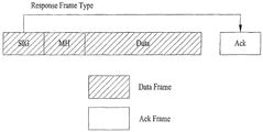
도 15는 PLCP 헤더의 SIG 필드의 응답 프레임 타입 필드를 사용하는 본 발명의 예시를 설명하기 위한 도면이다.
도 16은 본 발명의 일례에 따른 방법을 설명하기 위한 도면이다.
도 17은 본 발명의 일 실시예에 따른 무선 장치의 구성을 나타내는 블록도이다.BRIEF DESCRIPTION OF THE DRAWINGS The accompanying drawings, which are included to provide a further understanding of the invention, illustrate various embodiments of the invention and, together with the description, serve to explain the principles of the invention.
1 is a diagram showing an exemplary structure of an IEEE 802.11 system to which the present invention can be applied.
2 is a diagram showing another exemplary structure of an IEEE 802.11 system to which the present invention can be applied.
3 is a diagram showing another exemplary structure of an IEEE 802.11 system to which the present invention can be applied.
4 is a diagram showing an exemplary structure of a wireless LAN system.
5 is a diagram for explaining a link setup process in a wireless LAN system.
6 is a diagram for explaining a backoff process.
7 is a diagram for explaining hidden nodes and exposed nodes.
8 is a diagram for explaining RTS and CTS.
9 is a view for explaining an example of a frame structure used in the IEEE 802.11 system.
10 is a diagram showing an example of the
11 is a diagram showing an example of a short format of
12 is a diagram showing an example of a format longer than
13 is a diagram for explaining an ACK process.
14 is a diagram for explaining whether or not the frame exchange sequence according to the example of the present invention is allowed.
15 is a diagram for explaining an example of the present invention using the response frame type field of the SIG field of the PLCP header.
16 is a diagram for explaining a method according to an example of the present invention.
17 is a block diagram illustrating a configuration of a wireless device according to an embodiment of the present invention.
이하, 본 발명에 따른 바람직한 실시 형태를 첨부된 도면을 참조하여 상세하게 설명한다. 첨부된 도면과 함께 이하에 개시될 상세한 설명은 본 발명의 예시적인 실시형태를 설명하고자 하는 것이며, 본 발명이 실시될 수 있는 유일한 실시형태를 나타내고자 하는 것이 아니다. 이하의 상세한 설명은 본 발명의 완전한 이해를 제공하기 위해서 구체적 세부사항을 포함한다. 그러나, 당업자는 본 발명이 이러한 구체적 세부사항 없이도 실시될 수 있음을 안다.Hereinafter, preferred embodiments according to the present invention will be described in detail with reference to the accompanying drawings. DETAILED DESCRIPTION OF THE PREFERRED EMBODIMENTS The following detailed description, together with the accompanying drawings, is intended to illustrate exemplary embodiments of the invention and is not intended to represent the only embodiments in which the invention may be practiced. The following detailed description includes specific details in order to provide a thorough understanding of the present invention. However, those skilled in the art will appreciate that the present invention may be practiced without these specific details.
이하의 실시예들은 본 발명의 구성요소들과 특징들을 소정 형태로 결합한 것들이다. 각 구성요소 또는 특징은 별도의 명시적 언급이 없는 한 선택적인 것으로 고려될 수 있다. 각 구성요소 또는 특징은 다른 구성요소나 특징과 결합되지 않은 형태로 실시될 수 있다. 또한, 일부 구성요소들 및/또는 특징들을 결합하여 본 발명의 실시예를 구성할 수도 있다. 본 발명의 실시예들에서 설명되는 동작들의 순서는 변경될 수 있다. 어느 실시예의 일부 구성이나 특징은 다른 실시예에 포함될 수 있고, 또는 다른 실시예의 대응하는 구성 또는 특징과 교체될 수 있다.The following embodiments are a combination of elements and features of the present invention in a predetermined form. Each component or characteristic may be considered optional unless otherwise expressly stated. Each component or feature may be implemented in a form that is not combined with other components or features. In addition, some of the elements and / or features may be combined to form an embodiment of the present invention. The order of the operations described in the embodiments of the present invention may be changed. Some configurations or features of certain embodiments may be included in other embodiments, or may be replaced with corresponding configurations or features of other embodiments.
*이하의 설명에서 사용되는 특정 용어들은 본 발명의 이해를 돕기 위해서 제공된 것이며, 이러한 특정 용어의 사용은 본 발명의 기술적 사상을 벗어나지 않는 범위에서 다른 형태로 변경될 수 있다.The specific terminology used in the following description is provided for the purpose of helping understanding of the present invention, and the use of such specific terminology may be changed into other forms without departing from the technical idea of the present invention.
몇몇 경우, 본 발명의 개념이 모호해지는 것을 피하기 위하여 공지의 구조 및 장치는 생략되거나, 각 구조 및 장치의 핵심기능을 중심으로 한 블록도 형식으로 도시된다. 또한, 본 명세서 전체에서 동일한 구성요소에 대해서는 동일한 도면 부호를 사용하여 설명한다.In some instances, well-known structures and devices are omitted or shown in block diagram form around the core functions of each structure and device in order to avoid obscuring the concepts of the present invention. In the following description, the same components are denoted by the same reference numerals throughout the specification.
본 발명의 실시예들은 무선 액세스 시스템들인 IEEE 802 시스템, 3GPP 시스템, 3GPP LTE 및 LTE-A(LTE-Advanced)시스템 및 3GPP2 시스템 중 적어도 하나에 개시된 표준 문서들에 의해 뒷받침될 수 있다. 즉, 본 발명의 실시예들 중 본 발명의 기술적 사상을 명확히 드러내기 위해 설명하지 않은 단계들 또는 부분들은 상기 문서들에 의해 뒷받침될 수 있다. 또한, 본 문서에서 개시하고 있는 모든 용어들은 상기 표준 문서에 의해 설명될 수 있다.Embodiments of the present invention may be supported by standard documents disclosed in at least one of IEEE 802 systems, 3GPP systems, 3GPP LTE and LTE-Advanced (LTE-Advanced) systems and 3GPP2 systems, which are wireless access systems. That is, the steps or portions of the embodiments of the present invention that are not described in order to clearly illustrate the technical idea of the present invention can be supported by the documents. In addition, all terms disclosed in this document may be described by the standard document.
이하의 기술은 CDMA(Code Division Multiple Access), FDMA(Frequency Division Multiple Access), TDMA(Time Division Multiple Access), OFDMA(Orthogonal Frequency Division Multiple Access), SC-FDMA(Single Carrier Frequency Division Multiple Access) 등과 같은 다양한 무선 액세스 시스템에 사용될 수 있다. CDMA는 UTRA(Universal Terrestrial Radio Access)나 CDMA2000과 같은 무선 기술(radio technology)로 구현될 수 있다. TDMA는 GSM(Global System for Mobile communications)/GPRS(General Packet Radio Service)/EDGE(Enhanced Data Rates for GSM Evolution)와 같은 무선 기술로 구현될 수 있다. OFDMA는 IEEE 802.11 (Wi-Fi), IEEE 802.16 (WiMAX), IEEE 802-20, E-UTRA(Evolved UTRA) 등과 같은 무선 기술로 구현될 수 있다. 명확성을 위하여 이하에서는 IEEE 802.11 시스템을 위주로 설명하지만 본 발명의 기술적 사상이 이에 제한되는 것은 아니다.The following description will be made on the assumption that the present invention is applicable to a CDMA system such as Code Division Multiple Access (CDMA), Frequency Division Multiple Access (FDMA), Time Division Multiple Access (TDMA), Orthogonal Frequency Division Multiple Access (OFDMA), and Single Carrier Frequency Division Multiple Access And can be used in various radio access systems. CDMA may be implemented in radio technology such as Universal Terrestrial Radio Access (UTRA) or CDMA2000. The TDMA may be implemented in a wireless technology such as Global System for Mobile communications (GSM) / General Packet Radio Service (GPRS) / Enhanced Data Rates for GSM Evolution (EDGE). OFDMA may be implemented in wireless technologies such as IEEE 802.11 (Wi-Fi), IEEE 802.16 (WiMAX), IEEE 802-20, and Evolved UTRA (E-UTRA). For clarity, the following description will focus on the IEEE 802.11 system, but the technical idea of the present invention is not limited thereto.
WLAN 시스템의 구조Structure of WLAN system
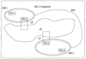
도 1 은 본 발명이 적용될 수 있는 IEEE 802.11 시스템의 예시적인 구조를 나타내는 도면이다.1 is a diagram showing an exemplary structure of an IEEE 802.11 system to which the present invention can be applied.
IEEE 802.11 구조는 복수개의 구성요소들로 구성될 수 있고, 이들의 상호작용에 의해 상위계층에 대해 트랜스패런트한 STA 이동성을 지원하는 WLAN이 제공될 수 있다. 기본 서비스 세트(Basic Service Set; BSS)는 IEEE 802.11 LAN에서의 기본적인 구성 블록에 해당할 수 있다. 도 1 에서는 2 개의 BSS(BSS1 및 BSS2)가 존재하고 각각의 BSS의 멤버로서 2 개의 STA이 포함되는 것(STA1 및 STA2 는 BSS1에 포함되고, STA3 및 STA4는 BSS2에 포함됨)을 예시적으로 도시한다. 도 1 에서 BSS를 나타내는 타원은 해당 BSS에 포함된 STA들이 통신을 유지하는 커버리지 영역을 나타내는 것으로도 이해될 수 있다. 이 영역을 BSA(Basic Service Area)라고 칭할 수 있다. STA이 BSA 밖으로 이동하게 되면 해당 BSA 내의 다른 STA들과 직접적으로 통신할 수 없게 된다.The IEEE 802.11 architecture can be composed of a plurality of components, and their interaction can provide a WLAN that supports STA mobility that is transparent to the upper layer. A Basic Service Set (BSS) may correspond to a basic building block in an IEEE 802.11 LAN. In FIG. 1, two BSSs (BSS1 and BSS2) exist and two STAs are included as members of each BSS (STA1 and STA2 are included in BSS1, and STA3 and STA4 are included in BSS2) do. In Fig. 1, an ellipse representing a BSS may be understood as indicating a coverage area in which STAs included in the corresponding BSS maintain communication. This area can be referred to as a BSA (Basic Service Area). If the STA moves out of the BSA, it will not be able to communicate directly with other STAs in the BSA.
IEEE 802.11 LAN에서 가장 기본적인 타입의 BSS는 독립적인 BSS(Independent BSS; IBSS)이다. 예를 들어, IBSS는 2 개의 STA만으로 구성된 최소의 형태를 가질 수 있다. 또한, 가장 단순한 형태이고 다른 구성요소들이 생략되어 있는 도 1 의 BSS(BSS1 또는 BSS2)가 IBSS의 대표적인 예시에 해당할 수 있다. 이러한 구성은 STA들이 직접 통신할 수 있는 경우에 가능하다. 또한, 이러한 형태의 LAN은 미리 계획되어서 구성되는 것이 아니라 LAN이 필요한 경우에 구성될 수 있으며, 이를 애드-혹(ad-hoc) 네트워크라고 칭할 수도 있다.The most basic type of BSS in an IEEE 802.11 LAN is an independent BSS (IBSS). For example, an IBSS may have a minimal form consisting of only two STAs. Also, the BSS (BSS1 or BSS2) of FIG. 1, which is the simplest form and the other components are omitted, may be a representative example of the IBSS. This configuration is possible when STAs can communicate directly. Also, this type of LAN may not be configured in advance, but may be configured when a LAN is required, which may be referred to as an ad-hoc network.
STA의 켜지거나 꺼짐, STA이 BSS 영역에 들어오거나 나감 등에 의해서, BSS에서의 STA의 멤버십이 동적으로 변경될 수 있다. BSS의 멤버가 되기 위해서는, STA은 동기화 과정을 이용하여 BSS에 조인할 수 있다. BSS 기반구조의 모든 서비스에 액세스하기 위해서는, STA은 BSS에 연관(associated)되어야 한다. 이러한 연관(association)은 동적으로 설정될 수 있고, 분배시스템서비스(Distribution System Service; DSS)의 이용을 포함할 수 있다.The STA's membership in the BSS can be changed dynamically, such as by turning the STA on or off, by the STA entering or leaving the BSS region, and so on. In order to become a member of the BSS, the STA can join the BSS using the synchronization process. In order to access all services of the BSS infrastructure, the STA must be associated with the BSS. This association may be set dynamically and may include the use of a Distribution System Service (DSS).
도 2 는 본 발명이 적용될 수 있는 IEEE 802.11 시스템의 다른 예시적인 구조를 나타내는 도면이다. 도 2 에서는 도 1 의 구조에서 분배시스템(Distribution System; DS), 분배시스템매체(Distribution System Medium; DSM), 액세스 포인트(Access Point; AP) 등의 구성요소가 추가된 형태이다.2 is a diagram showing another exemplary structure of an IEEE 802.11 system to which the present invention can be applied. 2, components such as a distribution system (DS), a distribution system medium (DSM), and an access point (AP) are added in the structure of FIG.
LAN에서 직접적인 스테이션-대-스테이션의 거리는 PHY 성능에 의해서 제한될 수 있다. 어떠한 경우에는 이러한 거리의 한계가 충분할 수도 있지만, 경우에 따라서는 보다 먼 거리의 스테이션 간의 통신이 필요할 수도 있다. 확장된 커버리지를 지원하기 위해서 분배시스템(DS)이 구성될 수 있다.The distance of the station-to-station directly from the LAN may be limited by the PHY performance. In some cases, the limits of such distances may be sufficient, but in some cases communication between stations at greater distances may be required. A distribution system (DS) can be configured to support extended coverage.
DS는 BSS들이 상호연결되는 구조를 의미한다. 구체적으로, 도 1 과 같이 BSS가 독립적으로 존재하는 대신에, 복수개의 BSS들로 구성된 네트워크의 확장된 형태의 구성요소로서 BSS가 존재할 수도 있다.DS means a structure in which BSSs are interconnected. Specifically, instead of the BSSs existing independently as shown in FIG. 1, there may be a BSS as an extended type component of a network composed of a plurality of BSSs.
DS는 논리적인 개념이며 분배시스템매체(DSM)의 특성에 의해서 특정될 수 있다. 이와 관련하여, IEEE 802.11 표준에서는 무선 매체(Wireless Medium; WM)와 분배시스템매체(DSM)을 논리적으로 구분하고 있다. 각각의 논리적 매체는 상이한 목적을 위해서 사용되며, 상이한 구성요소에 의해서 사용된다. IEEE 802.11 표준의 정의에서는 이러한 매체들이 동일한 것으로 제한하지도 않고 상이한 것으로 제한하지도 않는다. 이와 같이 복수개의 매체들이 논리적으로 상이하다는 점에서, IEEE 802.11 LAN 구조(DS 구조 또는 다른 네트워크 구조)의 유연성이 설명될 수 있다. 즉, IEEE 802.11 LAN 구조는 다양하게 구현될 수 있으며, 각각의 구현예의 물리적인 특성에 의해서 독립적으로 해당 LAN 구조가 특정될 수 있다.DS is a logical concept and can be specified by the characteristics of the distribution system medium (DSM). In this regard, the IEEE 802.11 standard logically distinguishes between a wireless medium (WM) and a distribution system medium (DSM). Each logical medium is used for different purposes and is used by different components. In the definition of the IEEE 802.11 standard, these media are not limited to the same or different. In this way, the flexibility of an IEEE 802.11 LAN architecture (DS structure or other network structure) can be described in that a plurality of media are logically different. That is, the IEEE 802.11 LAN structure can be variously implemented, and the LAN structure can be specified independently according to the physical characteristics of each implementation.
DS는 복수개의 BSS들의 끊김 없는(seamless) 통합을 제공하고 목적지로의 어드레스를 다루는 데에 필요한 논리적 서비스들을 제공함으로써 이동 기기를 지원할 수 있다.The DS can support mobile devices by providing seamless integration of a plurality of BSSs and providing the logical services needed to address addresses to destinations.
AP 는, 연관된 STA들에 대해서 WM을 통해서 DS 로의 액세스를 가능하게 하고 STA 기능성을 가지는 엔티티(entity)를 의미한다. AP를 통해서 BSS 및 DS 간의 데이터 이동이 수행될 수 있다. 예를 들어, 도 2 에서 도시하는 STA2 및 STA3 은 STA의 기능성을 가지면서, 연관된 STA들(STA1 및 STA4)가 DS로 액세스하도록 하는 기능을 제공한다. 또한, 모든 AP는 기본적으로 STA에 해당하므로, 모든 AP는 어드레스 가능한 엔티티이다. WM 상에서의 통신을 위해 AP 에 의해서 사용되는 어드레스와 DSM 상에서의 통신을 위해 AP 에 의해서 사용되는 어드레스는 반드시 동일할 필요는 없다.An AP is an entity that enables access to the DS through WM for the associated STAs and has STA functionality. Data movement between the BSS and the DS can be performed through the AP. For example, STA2 and STA3 shown in FIG. 2 have a function of the STA and provide a function of allowing the associated STAs (STA1 and STA4) to access the DS. Also, since all APs are basically STAs, all APs are addressable entities. The address used by the AP for communication on the WM and the address used by the AP for communication on the DSM do not necessarily have to be the same.
AP에 연관된 STA들 중의 하나로부터 그 AP의 STA 어드레스로 송신되는 데이터는, 항상 비제어 포트(uncontrolled port)에서 수신되고 IEEE 802.1X 포트 액세스 엔티티에 의해서 처리될 수 있다. 또한, 제어 포트(controlled port)가 인증되면 송신 데이터(또는 프레임)는 DS로 전달될 수 있다.Data transmitted from one of the STAs associated with the AP to the STA address of that AP is always received at the uncontrolled port and can be processed by the IEEE 802.1X port access entity. Also, when the controlled port is authenticated, the transmission data (or frame) may be delivered to the DS.
도 3 은 본 발명이 적용될 수 있는 IEEE 802.11 시스템의 또 다른 예시적인 구조를 나타내는 도면이다. 도 3 에서는 도 2 의 구조에 추가적으로 넓은 커버리지를 제공하기 위한 확장된 서비스 세트(Extended Service Set; ESS)를 개념적으로 나타낸다.3 is a diagram showing another exemplary structure of an IEEE 802.11 system to which the present invention can be applied. FIG. 3 conceptually illustrates an extended service set (ESS) for providing a wide coverage in addition to the structure of FIG.
임의의(arbitrary) 크기 및 복잡도를 가지는 무선 네트워크가 DS 및 BSS들로 구성될 수 있다. IEEE 802.11 시스템에서는 이러한 방식의 네트워크를 ESS 네트워크라고 칭한다. ESS는 하나의 DS에 연결된 BSS들의 집합에 해당할 수 있다. 그러나, ESS는 DS를 포함하지는 않는다. ESS 네트워크는 LLC(Logical Link Control) 계층에서 IBSS 네트워크로 보이는 점이 특징이다. ESS에 포함되는 STA들은 서로 통신할 수 있고, 이동 STA들은 LLC에 트랜스패런트하게 하나의 BSS에서 다른 BSS로 (동일한 ESS 내에서) 이동할 수 있다.A wireless network with arbitrary size and complexity may be comprised of DS and BSSs. In the IEEE 802.11 system, this type of network is referred to as an ESS network. An ESS may correspond to a set of BSSs connected to one DS. However, ESS does not include DS. The ESS network is characterized by an IBSS network in the LLC (Logical Link Control) layer. STAs included in the ESS can communicate with each other, and moving STAs can move from one BSS to another (within the same ESS) transparently to the LLC.
IEEE 802.11 에서는 도 3 에서의 BSS들의 상대적인 물리적 위치에 대해서 아무것도 가정하지 않으며, 다음과 같은 형태가 모두 가능하다. BSS들은 부분적으로 중첩될 수 있고, 이는 연속적인 커버리지를 제공하기 위해서 일반적으로 이용되는 형태이다. 또한, BSS들은 물리적으로 연결되어 있지 않을 수 있고, 논리적으로는 BSS들 간의 거리에 제한은 없다. 또한, BSS들은 물리적으로 동일한 위치에 위치할 수 있고, 이는 리던던시를 제공하기 위해서 이용될 수 있다. 또한, 하나 (또는 하나 이상의) IBSS 또는 ESS 네트워크들이 하나 (또는 하나 이상의) ESS 네트워크로서 동일한 공간에 물리적으로 존재할 수 있다. 이는 ESS 네트워크가 존재하는 위치에 애드-혹 네트워크가 동작하는 경우나, 상이한 기관(organizations)에 의해서 물리적으로 중첩되는 IEEE 802.11 네트워크들이 구성되는 경우나, 동일한 위치에서 2 이상의 상이한 액세스 및 보안 정책이 필요한 경우 등에서의 ESS 네트워크 형태에 해당할 수 있다.In IEEE 802.11, nothing is assumed for the relative physical location of the BSSs in FIG. 3, and both of the following forms are possible. BSSs can be partially overlapping, which is a form commonly used to provide continuous coverage. Also, the BSSs may not be physically connected, and there is no limitation on the distance between the BSSs logically. Also, the BSSs can be physically located at the same location, which can be used to provide redundancy. Also, one (or more) IBSS or ESS networks may physically exist in the same space as one (or more than one) ESS network. This may be the case when the ad-hoc network is operating at the location where the ESS network is located or when IEEE 802.11 networks physically overlap by different organizations are configured, or when two or more different access and security policies are required at the same location And the ESS network type in the case of the ESS.
도 4 는 무선랜 시스템의 예시적인 구조를 나타내는 도면이다. 도 4 에서는 DS를 포함하는 기반 구조 BSS 의 일례가 도시된다.4 is a diagram showing an exemplary structure of a wireless LAN system. In Fig. 4, an example of an infrastructure BSS including DS is shown.
도 4 의 예시에서 BSS1 및 BSS2가 ESS를 구성한다. 무선랜 시스템에서 STA은 IEEE 802.11 의 MAC/PHY 규정에 따라 동작하는 기기이다. STA은 AP STA 및 비-AP(non-AP) STA을 포함한다. Non-AP STA은 랩탑 컴퓨터, 이동 전화기와 같이 일반적으로 사용자가 직접 다루는 기기에 해당한다. 도 4 의 예시에서 STA1, STA3, STA4 는 non-AP STA에 해당하고, STA2 및 STA5 는 AP STA 에 해당한다.In the example of FIG. 4, BSS1 and BSS2 constitute the ESS. In the wireless LAN system, the STA is a device operating according to the IEEE 802.11 MAC / PHY specification. The STA includes an AP STA and a non-AP STA. Non-AP STAs correspond to devices that are typically handled by the user, such as laptop computers and mobile phones. In the example of FIG. 4, STA1, STA3, and STA4 correspond to non-AP STA, and STA2 and STA5 correspond to AP STA.
이하의 설명에서 non-AP STA은 단말(terminal), 무선 송수신 유닛(Wireless Transmit/Receive Unit; WTRU), 사용자 장치(User Equipment; UE), 이동국(Mobile Station; MS), 이동단말(Mobile Terminal), 이동 가입자국(Mobile Subscriber Station; MSS) 등으로 칭할 수도 있다. 또한, AP는 다른 무선 통신 분야에서의 기지국(Base Station; BS), 노드-B(Node-B), 발전된 노드-B(evolved Node-B; eNB), 기저 송수신 시스템(Base Transceiver System; BTS), 펨토 기지국(Femto BS) 등에 대응하는 개념이다.In the following description, the non-AP STA includes a terminal, a wireless transmit / receive unit (WTRU), a user equipment (UE), a mobile station (MS) , A mobile subscriber station (MSS), or the like. Also, the AP may be a base station (BS), a node-B, an evolved Node-B (eNB), a base transceiver system (BTS) , A femto base station (Femto BS), and the like.
계층 구조Hierarchy
본 발명에서 설명하는 무선랜 시스템에서 동작하는 AP 및/또는 STA의 동작은 계층(layer) 구조의 관점에서 설명할 수 있다. 장치 구성의 측면에서 계층 구조는 프로세서에 의해서 구현될 수 있다. AP 또는 STA는 복수개의 계층 구조를 가질 수 있다. 예를 들어, 802.11 표준문서에서 다루는 계층 구조는 주로 DLL(Data Link Layer) 상의 MAC 서브계층(sublayer) 및 물리(PHY) 계층이다. PHY은 PLCP(Physical Layer Convergence Procedure) 개체, PMD(Physical Medium Dependent) 개체 등을 포함할 수 있다. MAC 서브계층 및 PHY은 각각 MLME(MAC sublayer Management Entity) 및 PLME((Physical Layer Management Entity)라고 칭하여지는 관리 개체들을 개념적으로 포함한다. 이러한 개체들은 계층 관리 기능이 작동하는 계층 관리 서비스 인터페이스를 제공한다.The operations of the AP and / or STA operating in the wireless LAN system described in the present invention can be described in terms of a layer structure. In terms of device configuration, the hierarchy can be implemented by a processor. The AP or STA may have a plurality of hierarchical structures. For example, the hierarchical structure covered in the 802.11 standard document is mainly a MAC sublayer and a physical (PHY) layer on a DLL (Data Link Layer). The PHY may include a Physical Layer Convergence Procedure (PLCP) entity, a PMD (Physical Medium Dependent) entity, and the like. The MAC sublayer and the PHY conceptually include management entities called a MAC sublayer management entity (MLME) and a physical layer management entity (PLME), respectively. These entities provide a layer management service interface in which a layer management function operates .
정확한 MAC 동작을 제공하기 위해서, SME(Station Management Entity) 가 각각의 AP/STA 내에 존재한다. SME는, 별도의 관리 플레인 내에 존재하거나 또는 따로 떨어져(off to the side) 있는 것으로 보일 수 있는, 계층 독립적인 개체이다. SME의 정확한 기능들은 본 문서에서 구체적으로 설명하지 않지만, 일반적으로는 다양한 계층 관리 개체(LME)들로부터 계층-종속적인 상태를 수집하고, 계층-특정 파라미터들의 값을 유사하게 설정하는 등의 기능을 담당하는 것으로 보일 수 있다. SME는 일반적으로 일반 시스템 관리 개체를 대표하여(on behalf of) 이러한 기능들을 수행하고, 표준 관리 프로토콜을 구현할 수 있다.In order to provide correct MAC operation, a Station Management Entity (SME) exists in each AP / STA. An SME is a layer-independent entity that may be present in a separate management plane or may appear to be off-the-side. Although the exact functions of the SME are not described in detail in this document, they generally include the ability to collect layer-dependent states from various Layer Management Entities (LMEs) and to set similar values for layer-specific parameters It can be seen as responsible. An SME typically performs these functions on behalf of a generic system management entity and can implement a standard management protocol.
전술한 개체들은 다양한 방식으로 상호작용한다. 예를 들어, 개체들 간에는 GET/SET 프리머티브(primitive)들을 교환(exchange)함으로써 상호작용할 수 있다. XX-GET.request 프리머티브는 주어진 MIB attribute(관리 정보 기반 속성 정보)의 값을 요청하기 위해 사용된다. XX-GET.confirm 프리머티브는, Status가 "성공"인 경우에는 적절한 MIB 속성 정보 값을 리턴하고, 그렇지 않으면 Status 필드에서 에러 지시를 리턴하기 위해 사용된다. XX-SET.request 프리머티브는 지시된 MIB 속성이 주어진 값으로 설정되도록 요청하기 위해 사용된다. 상기 MIB 속성이 특정 동작을 의미하는 경우, 이는 해당 동작이 수행되는 것을 요청하는 것이다. 그리고, XX-SET.confirm 프리머티브는 status가 "성공"인 경우에 지시된 MIB 속성이 요청된 값으로 설정되었음을 확인하여 주고, 그렇지 않으면 status 필드에 에러 조건을 리턴하기 위해 사용된다. MIB 속성이 특정 동작을 의미하는 경우, 이는 해당 동작이 수행되었음을 확인하여 준다.The aforementioned entities interact in various ways. For example, they can interact by exchanging GET / SET primitives between entities. The XX-GET.request primitive is used to request the value of a given MIB attribute. The XX-GET.confirm primitive returns the appropriate MIB attribute information value if the Status is "Success", otherwise it is used to return an error indication in the Status field. The XX-SET.request primitive is used to request that the indicated MIB attribute be set to the given value. If the MIB attribute indicates a specific operation, it is requested that the corresponding operation be performed. The XX-SET.confirm primitive confirms that the indicated MIB attribute is set to the requested value if the status is "success", otherwise it is used to return an error condition to the status field. If the MIB attribute indicates a specific operation, this confirms that the operation has been performed.
또한, MLME 및 SME는 다양한 MLME_GET/SET 프리머티브들을 MLME_SAP(Service Access Point)을 통하여 교환할 수 있다. 또한, 다양한 PLME_GET/SET 프리머티브들이, PLME_SAP을 통해서 PLME와 SME 사이에서 교환될 수 있고, MLME-PLME_SAP을 통해서 MLME와 PLME 사이에서 교환될 수 있다.In addition, MLME and SME can exchange various MLME_GET / SET primitives through MLME_SAP (Service Access Point). In addition, various PLME_GET / SET primitives can be exchanged between PLME and SME through PLME_SAP and exchanged between MLME and PLME through MLME-PLME_SAP.
링크 셋업 과정Link Setup Process
도 5는 일반적인 링크 셋업(link setup) 과정을 설명하기 위한 도면이다.5 is a diagram for explaining a general link setup process.
STA이 네트워크에 대해서 링크를 셋업하고 데이터를 송수신하기 위해서는, 먼저 네트워크를 발견(discovery)하고, 인증(authentication)을 수행하고, 연관(association)을 맺고(establish), 보안(security)을 위한 인증 절차 등을 거쳐야 한다. 링크 셋업 과정을 세션 개시 과정, 세션 셋업 과정이라고도 칭할 수 있다. 또한, 링크 셋업 과정의 발견, 인증, 연관, 보안 설정의 과정을 통칭하여 연관 과정이라고 칭할 수도 있다.In order for a STA to set up a link to a network and transmit and receive data, the STA first discovers a network, performs authentication, establishes an association, establishes an authentication procedure for security, . The link setup process may be referred to as a session initiation process or a session setup process. Also, the process of discovery, authentication, association, and security setting of the link setup process may be collectively referred to as an association process.
도 5를 참조하여 예시적인 링크 셋업 과정에 대해서 설명한다.An exemplary link setup procedure will be described with reference to FIG.
단계 S510에서 STA은 네트워크 발견 동작을 수행할 수 있다. 네트워크 발견 동작은 STA의 스캐닝(scanning) 동작을 포함할 수 있다. 즉, STA이 네트워크에 액세스하기 위해서는 참여 가능한 네트워크를 찾아야 한다. STA은 무선 네트워크에 참여하기 전에 호환 가능한 네트워크를 식별하여야 하는데, 특정 영역에 존재하는 네트워크 식별과정을 스캐닝이라고 한다.In step S510, the STA can perform a network discovery operation. The network discovery operation may include a scanning operation of the STA. In other words, in order for the STA to access the network, it must find a network that can participate. The STA must identify a compatible network before joining the wireless network. The process of identifying a network in a specific area is called scanning.
스캐닝 방식에는 능동적 스캐닝(active scanning)과 수동적 스캐닝(passive scanning)이 있다.The scanning methods include active scanning and passive scanning.
도 5에서는 예시적으로 능동적 스캐닝 과정을 포함하는 네트워크 발견 동작을 도시한다. 능동적 스캐닝에서 스캐닝을 수행하는 STA은 채널들을 옮기면서 주변에 어떤 AP가 존재하는지 탐색하기 위해 프로브 요청 프레임(probe request frame)을 송신하고 이에 대한 응답을 기다린다. 응답자(responder)는 프로브 요청 프레임을 송신한 STA에게 프로브 요청 프레임에 대한 응답으로 프로브 응답 프레임(probe response frame)을 송신한다. 여기에서, 응답자는 스캐닝되고 있는 채널의 BSS에서 마지막으로 비콘 프레임(beacon frame)을 송신한 STA일 수 있다. BSS에서는 AP가 비콘 프레임을 송신하므로 AP가 응답자가 되며, IBSS에서는 IBSS 내의 STA들이 돌아가면서 비콘 프레임을 송신하므로 응답자가 일정하지 않다. 예를 들어, 1번 채널에서 프로브 요청 프레임을 송신하고 1번 채널에서 프로브 응답 프레임을 수신한 STA은, 수신한 프로브 응답 프레임에 포함된 BSS 관련 정보를 저장하고 다음 채널(예를 들어, 2번 채널)로 이동하여 동일한 방법으로 스캐닝(즉, 2번 채널 상에서 프로브 요청/응답 송수신)을 수행할 수 있다.FIG. 5 illustrates a network discovery operation that includes an exemplary active scanning process. The STA performing the scanning in the active scanning transmits the probe request frame and waits for a response in order to search for the existence of an AP around the channels while moving the channels. The responder sends a probe response frame in response to the probe request frame to the STA that sent the probe request frame. Here, the responder may be the STA that last transmitted the beacon frame in the BSS of the channel being scanned. In the BSS, the AP transmits the beacon frame, so the AP becomes the responder. In the IBSS, the STAs in the IBSS transmit the beacon frame while the beacon frame is transmitted. For example, the STA that transmits the probe request frame in
도 5에서 도시하고 있지 않지만, 스캐닝 동작은 수동적 스캐닝 방식으로 수행될 수도 있다. 수동적 스캐닝에서 스캐닝을 수행하는 STA은 채널들을 옮기면서 비콘 프레임을 기다린다. 비콘 프레임은 IEEE 802.11에서 관리 프레임(management frame) 중 하나로서, 무선 네트워크의 존재를 알리고, 스캐닝을 수행하는 STA으로 하여금 무선 네트워크를 찾아서, 무선 네트워크에 참여할 수 있도록 주기적으로 송신된다. BSS에서 AP가 비콘 프레임을 주기적으로 송신하는 역할을 수행하고, IBSS에서는 IBSS 내의 STA들이 돌아가면서 비콘 프레임을 송신한다. 스캐닝을 수행하는 STA은 비콘 프레임을 수신하면 비콘 프레임에 포함된 BSS에 대한 정보를 저장하고 다른 채널로 이동하면서 각 채널에서 비콘 프레임 정보를 기록한다. 비콘 프레임을 수신한 STA은, 수신한 비콘 프레임에 포함된 BSS 관련 정보를 저장하고 다음 채널로 이동하여 동일한 방법으로 다음 채널에서 스캐닝을 수행할 수 있다.Although not shown in FIG. 5, the scanning operation may be performed in a passive scanning manner. In passive scanning, the STA performing the scanning waits for the beacon frame while moving the channels. The beacon frame is one of the management frames in IEEE 802.11, and is periodically transmitted to notify the presence of the wireless network and allow the STA performing the scanning to find the wireless network and participate in the wireless network. In the BSS, the AP periodically transmits the beacon frame, and in the IBSS, the beacon frame is transmitted while the STAs in the IBSS are running. Upon receiving the beacon frame, the scanning STA stores information on the BSS included in the beacon frame and records beacon frame information on each channel while moving to another channel. The STA receiving the beacon frame stores the BSS-related information included in the received beacon frame, moves to the next channel, and performs scanning in the next channel in the same manner.
능동적 스캐닝과 수동적 스캐닝을 비교하면, 능동적 스캐닝이 수동적 스캐닝보다 딜레이(delay) 및 전력 소모가 작은 장점이 있다.Comparing active scanning with passive scanning, active scanning has the advantage of less delay and less power consumption than passive scanning.
STA이 네트워크를 발견한 후에, 단계 S520에서 인증 과정이 수행될 수 있다. 이러한 인증 과정은 후술하는 단계 S540의 보안 셋업 동작과 명확하게 구분하기 위해서 첫 번째 인증(first authentication) 과정이라고 칭할 수 있다.After the STA finds the network, the authentication procedure may be performed in step S520. This authentication process can be referred to as a first authentication process in order to clearly distinguish from the security setup operation in step S540 described later.
인증 과정은 STA이 인증 요청 프레임(authentication request frame)을 AP에게 송신하고, 이에 응답하여 AP가 인증 응답 프레임(authentication response frame)을 STA에게 송신하는 과정을 포함한다. 인증 요청/응답에 사용되는 인증 프레임(authentication frame)은 관리 프레임에 해당한다.The authentication process includes an STA transmitting an authentication request frame to the AP, and an AP transmitting an authentication response frame to the STA in response to the authentication request frame. The authentication frame used for the authentication request / response corresponds to the management frame.
인증 프레임은 인증 알고리즘 번호(authentication algorithm number), 인증 트랜잭션 시퀀스 번호(authentication transaction sequence number), 상태 코드(status code), 검문 텍스트(challenge text), RSN(Robust Security Network), 유한 순환 그룹(Finite Cyclic Group) 등에 대한 정보를 포함할 수 있다. 이는 인증 요청/응답 프레임에 포함될 수 있는 정보들의 일부 예시에 해당하며, 다른 정보로 대체되거나, 추가적인 정보가 더 포함될 수 있다.The authentication frame includes an authentication algorithm number, an authentication transaction sequence number, a status code, a challenge text, a robust security network (RSN), a finite cyclic group Group), and the like. This corresponds to some examples of information that may be included in the authentication request / response frame, may be replaced by other information, or may include additional information.
STA은 인증 요청 프레임을 AP에게 송신할 수 있다. AP는 수신된 인증 요청 프레임에 포함된 정보에 기초하여, 해당 STA에 대한 인증을 허용할지 여부를 결정할 수 있다. AP는 인증 처리의 결과를 인증 응답 프레임을 통하여 STA에게 제공할 수 있다.The STA may send an authentication request frame to the AP. Based on the information included in the received authentication request frame, the AP can determine whether or not to allow authentication for the STA. The AP can provide the result of the authentication process to the STA through the authentication response frame.
STA이 성공적으로 인증된 후에, 단계 S530에서 연관 과정이 수행될 수 있다. 연관 과정은 STA이 연관 요청 프레임(association request frame)을 AP에게 송신하고, 이에 응답하여 AP가 연관 응답 프레임(association response frame)을 STA에게 송신하는 과정을 포함한다.After the STA has been successfully authenticated, the association process may be performed in step S530. The association process includes the STA sending an association request frame to the AP, and in response, the AP sending an association response frame to the STA.
예를 들어, 연관 요청 프레임은 다양한 능력(capability)에 관련된 정보, 비콘 청취 간격(listen interval), SSID(service set identifier), 지원 레이트(supported rates), 지원 채널(supported channels), RSN, 이동성 도메인, 지원 오퍼레이팅 클래스(supported operating classes), TIM 방송 요청(Traffic Indication Map Broadcast request), 상호동작(interworking) 서비스 능력 등에 대한 정보를 포함할 수 있다.For example, the association request frame may include information related to various capabilities, a listening interval, a service set identifier (SSID), supported rates, supported channels, an RSN, , Supported operating classes, TIM broadcast request, interworking service capability, and the like.
예를 들어, 연관 응답 프레임은 다양한 능력에 관련된 정보, 상태 코드, AID(Association ID), 지원 레이트, EDCA(Enhanced Distributed Channel Access) 파라미터 세트, RCPI(Received Channel Power Indicator), RSNI(Received Signal to Noise Indicator), 이동성 도메인, 타임아웃 간격(연관 컴백 시간(association comeback time)), 중첩(overlapping) BSS 스캔 파라미터, TIM 방송 응답, QoS 맵 등의 정보를 포함할 수 있다.For example, the association response frame may include information related to various capabilities, a status code, an association ID (AID), a support rate, an enhanced distributed channel access (EDCA) parameter set, a Received Channel Power Indicator (RCPI) A timeout interval (an association comeback time), a overlapping BSS scan parameter, a TIM broadcast response, a QoS map, and the like.
이는 연관 요청/응답 프레임에 포함될 수 있는 정보들의 일부 예시에 해당하며, 다른 정보로 대체되거나, 추가적인 정보가 더 포함될 수 있다.This corresponds to some examples of information that may be included in the association request / response frame, may be replaced by other information, or may include additional information.
STA이 네트워크에 성공적으로 연관된 후에, 단계 S540에서 보안 셋업 과정이 수행될 수 있다. 단계 S540의 보안 셋업 과정은 RSNA(Robust Security Network Association) 요청/응답을 통한 인증 과정이라고 할 수도 있고, 상기 단계 S520의 인증 과정을 첫 번째 인증(first authentication) 과정이라고 하고, 단계 S540의 보안 셋업 과정을 단순히 인증 과정이라고도 칭할 수도 있다.After the STA is successfully associated with the network, a security setup procedure may be performed at step S540. The security setup process of step S540 may be referred to as an authentication process through a Robust Security Network Association (RSNA) request / response. The authentication process of step S520 may be referred to as a first authentication process, May also be referred to simply as an authentication process.
단계 S540의 보안 셋업 과정은, 예를 들어, EAPOL(Extensible Authentication Protocol over LAN) 프레임을 통한 4-웨이(way) 핸드쉐이킹을 통해서, 프라이빗 키 셋업(private key setup)을 하는 과정을 포함할 수 있다. 또한, 보안 셋업 과정은 IEEE 802.11 표준에서 정의하지 않는 보안 방식에 따라 수행될 수도 있다.The security setup process of step S540 may include a private key setup through 4-way handshaking over an Extensible Authentication Protocol over LAN (EAPOL) frame, for example . In addition, the security setup process may be performed according to a security scheme not defined in the IEEE 802.11 standard.
WLAN의 진화Evolution of WLAN
무선랜에서 통신 속도에 대한 한계를 극복하기 위하여 비교적 최근에 제정된 기술 표준으로서 IEEE 802.11n이 존재한다. IEEE 802.11n은 네트워크의 속도와 신뢰성을 증가시키고, 무선 네트워크의 운영 거리를 확장하는데 목적을 두고 있다. 보다 구체적으로, IEEE 802.11n에서는 데이터 처리 속도가 최대 540Mbps 이상인 고처리율(High Throughput; HT)을 지원하며, 또한 송신 에러를 최소화하고 데이터 속도를 최적화하기 위해 송신부와 수신부 양단 모두에 다중 안테나를 사용하는 MIMO(Multiple Inputs and Multiple Outputs) 기술에 기반을 두고 있다.In order to overcome the limitation of the communication speed in the wireless LAN, IEEE 802.11n exists as a relatively recently established technical standard. IEEE 802.11n aims to increase the speed and reliability of the network and to extend the operating distance of the wireless network. More specifically, in IEEE 802.11n, high throughput (HT) with a data processing speed of 540 Mbps or higher is supported, and multiple antennas are used at both ends of a transmitter and a receiver in order to minimize transmission error and optimize data rate It is based on Multiple Inputs and Multiple Outputs (MIMO) technology.
무선랜의 보급이 활성화되고 또한 이를 이용한 어플리케이션이 다양화됨에 따라, 최근에는 IEEE 802.11n이 지원하는 데이터 처리 속도보다 더 높은 처리율을 지원하기 위한 새로운 무선랜 시스템에 대한 필요성이 대두되고 있다. 초고처리율(Very High Throughput; VHT)를 지원하는 차세대 무선랜 시스템은 IEEE 802.11n 무선랜 시스템의 다음 버전(예를 들어, IEEE 802.11ac)으로서, MAC 서비스 액세스 포인트(Service Access Point; SAP)에서 1Gbps 이상의 데이터 처리 속도를 지원하기 위하여 최근에 새롭게 제안되고 있는 IEEE 802.11 무선랜 시스템중의 하나이다.With the spread of wireless LANs and the diversification of applications using them, there is a need for a new wireless LAN system to support higher throughput than the data processing rate supported by IEEE 802.11n. The next generation wireless LAN system supporting very high throughput (VHT) is a next version of IEEE 802.11n wireless LAN system (for example, IEEE 802.11ac), and it has a MAC service access point (SAP) The IEEE 802.11 wireless LAN system is one of the newly proposed wireless LAN systems.
차세대 무선랜 시스템은 무선채널을 효율적으로 이용하기 위하여 복수의 STA들이 동시에 채널에 액세스하는 MU-MIMO(Multi User Multiple Input Multiple Output) 방식의 송신을 지원한다. MU-MIMO 송신 방식에 따르면, AP가 MIMO 페어링(pairing)된 하나 이상의 STA에게 동시에 패킷을 송신할 수 있다.The next generation wireless LAN system supports transmission of MU-MIMO (Multi User Multiple Input Multiple Output) method in which a plurality of STAs simultaneously access channels in order to utilize wireless channels efficiently. According to the MU-MIMO transmission scheme, an AP can simultaneously transmit packets to one or more MIMO-paired STAs.
또한, 화이트스페이스(whitespace)에서 무선랜 시스템 동작을 지원하는 것이 논의되고 있다. 예를 들어, 아날로그 TV의 디지털화로 인한 유휴 상태의 주파수 대역(예를 들어, 54~698MHz 대역)과 같은 TV 화이트스페이스(TV WS)에서의 무선랜 시스템의 도입은 IEEE 802.11af 표준으로서 논의되고 있다. 하지만, 이는 예시에 불과하고, 화이트스페이스는 허가된 유저(licensed user)가 우선적으로 사용할 수 있는 허가된 대역이라 할 수 있다. 허가된 유저는 허가된 대역의 사용을 허가 받은 유저를 의미하며, 허가된 장치(licensed device), 프라이머리 유저(primary user), 우선적 사용자(incumbent user) 등으로 칭할 수도 있다.It is also discussed to support the operation of a wireless LAN system in whitespace. For example, the introduction of a WLAN system in a TV white space (TV WS), such as an idle frequency band (e.g., 54 MHz to 698 MHz band) due to the digitization of an analog TV, has been discussed as an IEEE 802.11af standard . However, this is merely an example, and the whitespace may be an authorized band that a licensed user may prefer to use. An authorized user is a user who is authorized to use an authorized band, and may be referred to as a licensed device, a primary user, an incumbent user, or the like.
예를 들어, WS에서 동작하는 AP 및/또는 STA은 허가된 유저에 대한 보호(protection) 기능을 제공하여야 한다. 예를 들어 WS 대역에서 특정 대역폭을 가지도록 규약(regulation)상 분할되어 있는 주파수 대역인 특정 WS 채널을 마이크로폰(microphone)과 같은 허가된 유저가 이미 사용하고 있는 경우, 허가된 유저를 보호하기 위하여 AP 및/또는 STA은 해당 WS 채널에 해당하는 주파수 대역은 사용할 수 없다. 또한, AP 및/또는 STA은 현재 프레임 송신 및/또는 수신을 위해 사용하고 있는 주파수 대역을 허가된 유저가 사용하게 되면 해당 주파수 대역의 사용을 중지해야 한다.For example, an AP and / or STA operating on a WS must provide protection for an authorized user. For example, if an authorized user such as a microphone already uses a specific WS channel, which is a frequency band that is divided in regulation so as to have a specific bandwidth in the WS band, And / or the STA can not use the frequency band corresponding to that WS channel. In addition, the AP and / or the STA should stop using the frequency band used for the current frame transmission and / or reception when the authorized user uses the frequency band.
따라서 AP 및/또는STA은 WS 대역 내 특정 주파수 대역의 사용이 가능한지, 다시 말해서 상기 주파수 대역에 허가된 유저가 있는지 여부를 파악하는 절차가 선행되어야 한다. 특정 주파수 대역에 허가된 유저가 있는지 여부를 파악하는 것을 스펙트럼 센싱(spectrum sensing)이라 한다. 스펙트럼 센싱 메커니즘으로 에너지 탐지(energy detection) 방식, 신호 탐지(signature detection) 방식 등이 활용된다. 수신 신호의 강도가 일정 값 이상이면 허가된 유저가 사용중인 것으로 판단하거나, DTV 프리앰블(preamble)이 검출되면 허가된 유저가 사용중인 것으로 판단할 수 있다.Therefore, the AP and / or the STA must precede the process of determining whether a specific frequency band in the WS band can be used, in other words, whether or not there is an authorized user in the frequency band. Knowing whether or not there is a user authorized in a specific frequency band is called spectrum sensing. The spectrum sensing mechanism uses energy detection method and signature detection method. If the strength of the received signal is equal to or greater than a predetermined value, it is determined that the authorized user is in use, or it is determined that the authorized user is using the DTV preamble when the preamble is detected.
또한, 차세대 통신 기술로서 M2M(Machine-to-Machine) 통신 기술이 논의되고 있다. IEEE 802.11 무선랜 시스템에서도 M2M 통신을 지원하기 위한 기술 표준이 IEEE 802.11ah로서 개발되고 있다. M2M 통신은 하나 이상의 머신(Machine)이 포함되는 통신 방식을 의미하며, MTC(Machine Type Communication) 또는 사물 통신으로 칭하여지기도 한다. 여기서, 머신이란 사람의 직접적인 조작이나 개입을 필요로 하지 않는 엔티티(entity)를 의미한다. 예를 들어, 무선 통신 모듈이 탑재된 검침기(meter)나 자동 판매기와 같은 장치는 물론, 사용자의 조작/개입없이 자동으로 네트워크에 접속하여 통신을 수행할 수 있는 스마트폰과 같은 사용자 기기도 머신의 예시에 해당할 수 있다. M2M 통신은 디바이스 간의 통신(예를 들어, D2D(Device-to-Device) 통신), 디바이스와 서버(application server) 간의 통신 등을 포함할 수 있다. 디바이스와 서버 통신의 예시로, 자동 판매기와 서버, POS(Point of Sale) 장치와 서버, 전기, 가스 또는 수도 검침기와 서버 간의 통신을 들 수 있다. 그 외에도 M2M 통신 기반의 애플리케이션(application)에는, 보안(security), 운송(transportation), 헬스 케어(health care) 등이 포함될 수 있다. 이러한 적용례의 특성을 고려하면, 일반적으로 M2M 통신은 매우 많은 기기가 존재하는 환경에서 가끔씩 적은 양의 데이터를 저속으로 송수신하는 것을 지원할 수 있어야 한다.In addition, M2M (Machine-to-Machine) communication technology is being discussed as a next generation communication technology. In IEEE 802.11 wireless LAN system, a technical standard for supporting M2M communication is being developed as IEEE 802.11ah. The M2M communication means a communication method including one or more machines, and may be referred to as MTC (Machine Type Communication) or object communication. Here, a machine means an entity that does not require direct manipulation or intervention of a person. For example, a user device such as a smart phone capable of automatically connecting to a network and performing communication without a user's operation / intervention, such as a meter or vending machine equipped with a wireless communication module, This can be an example. M2M communication may include communication between devices (e.g., device-to-device communication (D2D)), communication between a device and a server (application server) Examples of device and server communications include vending machines and servers, Point of Sale (POS) devices and servers, and electricity, gas or water meter and server communication. In addition, applications based on M2M communication may include security, transportation, health care, and the like. Given the nature of these applications, M2M communications in general should be able to support the transmission and reception of small amounts of data occasionally at low rates in environments with very large numbers of devices.
구체적으로, M2M 통신은 많은 STA의 개수를 지원할 수 있어야 한다. 현재 정의되어 있는 무선랜 시스템에서는 하나의 AP에 최대 2007 개의 STA이 연관되는 경우를 가정하지만, M2M 통신에서는 이보다 많은 개수(약 6000 개)의 STA이 하나의 AP에 연관되는 경우를 지원하는 방안들이 논의되고 있다. 또한, M2M 통신에서는 낮은 송신 속도를 지원/요구하는 애플리케이션이 많을 것으로 예상된다. 이를 원활하게 지원하기 위해서, 예를 들어, 무선랜 시스템에서는 TIM(Traffic Indication Map) 요소 기반으로 STA이 자신에게 송신될 데이터의 존재 여부를 인지할 수 있는데, TIM의 비트맵 크기를 줄이는 방안들이 논의되고 있다. 또한, M2M 통신에서는 송신/수신 간격이 매우 긴 트래픽이 많을 것으로 예상된다. 예를 들어, 전기/가스/수도 사용량과 같이 긴 주기(예를 들어, 한 달) 마다 매우 적은 양의 데이터를 주고 받는 것이 요구된다. 이에 따라, 무선랜 시스템에서는, 하나의 AP에 연관될 수 있는 STA의 개수는 매우 많아지더라도, 하나의 비콘 주기 동안에 AP로부터 수신할 데이터 프레임이 존재하는 STA의 개수가 매우 적은 경우를 효율적으로 지원하는 방안들이 논의되고 있다.Specifically, M2M communication must be capable of supporting the number of STAs. In the currently defined WLAN system, it is supposed that a maximum of 2007 STAs are associated with one AP. However, in the case of M2M communication, schemes for supporting a case where more than (about 6000) STAs are associated with one AP Are being discussed. In addition, M2M communication is expected to have many applications that support / require low transmission speed. In order to smoothly support this, for example, in a wireless LAN system, STA can recognize whether there is data to be transmitted to itself based on a Traffic Indication Map (TIM) element, and measures for reducing the bitmap size of TIM are discussed . Also, in M2M communication, it is expected that there will be many traffic with a very long transmission / reception interval. For example, a very small amount of data is required to be exchanged over a long period (for example, one month), such as electricity / gas / water usage. Accordingly, in the wireless LAN system, even if the number of STAs that can be associated with one AP becomes very large, it is possible to efficiently support a case in which the number of STAs having a data frame to be received from the AP is small during one beacon period Are discussed.
이와 같이 무선랜 기술은 빠르게 진화하게 있으며, 전술한 예시들 외에도 직접 링크 셋업, 미디어 스트리밍 성능의 개선, 고속 및/또는 대규모의 초기 세션 셋업의 지원, 확장된 대역폭 및 동작 주파수의 지원 등을 위한 기술이 개발되고 있다.In this way, the wireless LAN technology is rapidly evolving. In addition to the above-mentioned examples, techniques for direct link setup, improvement of media streaming performance, support for high-speed and / or large-scale initial session setup, support for extended bandwidth and operating frequency Is being developed.
매체 액세스 메커니즘Medium access mechanism
IEEE 802.11에 따른 무선랜 시스템에서, MAC(Medium Access Control)의 기본 액세스 메커니즘은 CSMA/CA(Carrier Sense Multiple Access with Collision Avoidance) 메커니즘이다. CSMA/CA 메커니즘은 IEEE 802.11 MAC의 분배 조정 기능(Distributed Coordination Function, DCF)이라고도 불리는데, 기본적으로 "listen before talk" 액세스 메커니즘을 채용하고 있다. 이러한 타입의 액세스 메커니즘 따르면, AP 및/또는 STA은 송신을 시작하기에 앞서, 소정의 시간구간(예를 들어, DIFS(DCF Inter-Frame Space) 동안 무선 채널 또는 매체(medium)를 센싱(sensing)하는 CCA(Clear Channel Assessment)를 수행할 수 있다. 센싱 결과, 만일 매체가 유휴 상태(idle status)인 것으로 판단 되면, 해당 매체를 통하여 프레임 송신을 시작한다. 반면, 매체가 점유 상태(occupied status)인 것으로 감지되면, 해당 AP 및/또는 STA은 자기 자신의 송신을 시작하지 않고 매체 액세스를 위한 지연 기간(예를 들어, 임의 백오프 주기(random backoff period))을 설정하여 기다린 후에 프레임 송신을 시도할 수 있다. 임의 백오프 주기의 적용으로, 여러 STA들은 서로 다른 시간 동안 대기한 후에 프레임 송신을 시도할 것이 기대되므로, 충돌(collision)을 최소화시킬 수 있다.In a wireless LAN system compliant with IEEE 802.11, the basic access mechanism of Medium Access Control (MAC) is a CSMA / CA (Carrier Sense Multiple Access with Collision Avoidance) mechanism. The CSMA / CA mechanism is also referred to as the Distributed Coordination Function (DCF) of the IEEE 802.11 MAC, which basically adopts a "listen before talk" access mechanism. According to this type of access mechanism, the AP and / or the STA may sense a radio channel or medium for a predetermined time interval (e.g., DCF Inter-Frame Space (DIFS) If the medium is judged to be in an idle state, the transmission of the frame is started through the corresponding medium. On the other hand, when the medium is in the occupied status, The AP and / or the STA attempts to transmit a frame after setting a delay period (e.g., a random backoff period) for media access without starting its own transmission With the application of an arbitrary backoff period, several STAs are expected to attempt to transmit frames after waiting for different times, thereby minimizing collisions.
또한, IEEE 802.11 MAC 프로토콜은 HCF(Hybrid Coordination Function)를 제공한다. HCF는 상기 DCF와 PCF(Point Coordination Function)를 기반으로 한다. PCF는 폴링(polling) 기반의 동기식 액세스 방식으로 모든 수신 AP 및/또는 STA이 데이터 프레임을 수신할 수 있도록 주기적으로 폴링하는 방식을 일컫는다. 또한, HCF는 EDCA(Enhanced Distributed Channel Access)와 HCCA(HCF Controlled Channel Access)를 가진다. EDCA는 제공자가 다수의 사용자에게 데이터 프레임을 제공하기 위한 액세스 방식을 경쟁 기반으로 하는 것이고, HCCA는 폴링(polling) 메커니즘을 이용한 비경쟁 기반의 채널 액세스 방식을 사용하는 것이다. 또한, HCF는 WLAN의 QoS(Quality of Service)를 향상시키기 위한 매체 액세스 메커니즘을 포함하며, 경쟁 주기(Contention Period; CP)와 비경쟁 주기(Contention Free Period; CFP) 모두에서 QoS 데이터를 송신할 수 있다.In addition, the IEEE 802.11 MAC protocol provides HCF (Hybrid Coordination Function). The HCF is based on the DCF and the PCF (Point Coordination Function). The PCF is a polling-based, synchronous access scheme that refers to periodically polling all receiving APs and / or STAs to receive data frames. In addition, HCF has EDCA (Enhanced Distributed Channel Access) and HCCA (HCF Controlled Channel Access). EDCA is a contention-based access method for a provider to provide data frames to a large number of users, and HCCA uses a contention-based channel access method using a polling mechanism. In addition, the HCF includes a medium access mechanism for improving the QoS (Quality of Service) of the WLAN, and can transmit QoS data in both a contention period (CP) and a contention free period (CFP) .
도 6은 백오프 과정을 설명하기 위한 도면이다.6 is a diagram for explaining a backoff process.
도 6을 참조하여 임의 백오프 주기에 기반한 동작에 대해서 설명한다. 점유(occupy 또는 busy) 상태이던 매체가 유휴(idle) 상태로 변경되면, 여러 STA들은 데이터(또는 프레임) 송신을 시도할 수 있다. 이 때, 충돌을 최소화하기 위한 방안으로서, STA들은 각각 임의 백오프 카운트를 선택하고 그에 해당하는 슬롯 시간만큼 대기한 후에, 송신을 시도할 수 있다. 임의 백오프 카운트는 의사-임의 정수(pseudo-random integer) 값을 가지며, 0 내지 CW 범위의 값 중에서 하나로 결정될 수 있다. 여기서, CW는 경쟁 윈도우(Contention Window) 파라미터 값이다. CW 파라미터는 초기값으로 CWmin이 주어지지만, 송신 실패의 경우(예를 들어, 송신된 프레임에 대한 ACK을 수신하지 못한 경우)에 2 배의 값을 취할 수 있다. CW 파라미터 값이 CWmax가 되면 데이터 송신이 성공할 때까지 CWmax 값을 유지하면서 데이터 송신을 시도할 수 있고, 데이터 송신이 성공하는 경우에는 CWmin 값으로 리셋된다. CW, CWmin 및 CWmax 값은 2n-1 (n=0, 1, 2, ...)로 설정되는 것이 바람직하다.An operation based on an arbitrary backoff period will be described with reference to FIG. When a medium that is in an occupy or busy state is changed to an idle state, several STAs may attempt to transmit data (or frames). At this time, as a method for minimizing the collision, each of the STAs may attempt to transmit after selecting an arbitrary backoff count and waiting for a corresponding slot time. An arbitrary backoff count has a pseudo-random integer value, and may be determined to be one of a value in the range of 0 to CW. Here, CW is a contention window parameter value. The CW parameter is given an initial value of CWmin, but it can take a value twice in case of transmission failure (for example, in the case of not receiving an ACK for a transmitted frame). When the CW parameter value reaches CWmax, data transmission can be attempted while maintaining the CWmax value until the data transmission is successful. If the data transmission is successful, the CWmin value is reset to the CWmin value. The values of CW, CWmin and CWmax are preferably set to 2 n -1 (n = 0, 1, 2, ...).
임의 백오프 과정이 시작되면 STA은 결정된 백오프 카운트 값에 따라서 백오프 슬롯을 카운트 다운하는 동안에 계속하여 매체를 모니터링한다. 매체가 점유상태로 모니터링되면 카운트 다운을 멈추고 대기하고, 매체가 유휴 상태가 되면 나머지 카운트 다운을 재개한다.When an arbitrary backoff process is started, the STA continuously monitors the medium while counting down the backoff slot according to the determined backoff count value. When the medium is monitored in the occupied state, the countdown is stopped and waited, and when the medium is idle, the remaining countdown is resumed.
도 6의 예시에서 STA3의 MAC에 송신할 패킷이 도달한 경우에, STA3는 DIFS 만큼 매체가 유휴 상태인 것을 확인하고 바로 프레임을 송신할 수 있다. 한편, 나머지 STA들은 매체가 점유(busy) 상태인 것을 모니터링하고 대기한다. 그 동안 STA1, STA2 및 STA5의 각각에서도 송신할 데이터가 발생할 수 있고, 각각의 STA은 매체가 유휴상태로 모니터링되면 DIFS만큼 대기한 후에, 각자가 선택한 임의 백오프 카운트 값에 따라 백오프 슬롯의 카운트 다운을 수행할 수 있다. 도 6의 예시에서는 STA2가 가장 작은 백오프 카운트 값을 선택하고, STA1이 가장 큰 백오프 카운트 값을 선택한 경우를 나타낸다. 즉, STA2가 백오프 카운트를 마치고 프레임 송신을 시작하는 시점에서 STA5의 잔여 백오프 시간은 STA1의 잔여 백오프 시간보다 짧은 경우를 예시한다. STA1 및 STA5는 STA2가 매체를 점유하는 동안에 잠시 카운트 다운을 멈추고 대기한다. STA2의 점유가 종료되어 매체가 다시 유휴상태가 되면, STA1 및 STA5는 DIFS만큼 대기한 후에, 멈추었던 백오프 카운트를 재개한다. 즉, 잔여 백오프 시간만큼의 나머지 백오프 슬롯을 카운트 다운한 후에 프레임 송신을 시작할 수 있다. STA5의 잔여 백오프 시간이 STA1보다 짧았으므로 STA5이 프레임 송신을 시작하게 된다. 한편, STA2가 매체를 점유하는 동안에 STA4에서도 송신할 데이터가 발생할 수 있다. 이 때, STA4의 입장에서는 매체가 유휴 상태가 되면 DIFS만큼 대기한 후, 자신이 선택한 임의 백오프 카운트 값에 따른 카운트 다운을 수행하고 프레임 송신을 시작할 수 있다. 도 6의 예시에서는 STA5의 잔여 백오프 시간이 STA4의 임의 백오프 카운트 값과 우연히 일치하는 경우를 나타내며, 이 경우, STA4와 STA5 간에 충돌이 발생할 수 있다. 충돌이 발생하는 경우에는 STA4와 STA5 모두 ACK을 받지 못하여, 데이터 송신을 실패하게 된다. 이 경우, STA4와 STA5는 CW 값을 2배로 늘린 후에 임의 백오프 카운트 값을 선택하고 카운트 다운을 수행할 수 있다. 한편, STA1은 STA4와 STA5의 송신으로 인해 매체가 점유 상태인 동안에 대기하고 있다가, 매체가 유휴 상태가 되면 DIFS만큼 대기한 후, 잔여 백오프 시간이 지나면 프레임 송신을 시작할 수 있다.In the example of FIG. 6, when a packet to be transmitted to the MAC of the STA3 arrives, the STA3 can confirm that the medium is idle by DIFS and transmit the frame immediately. Meanwhile, the remaining STAs monitor and wait for the medium to be in a busy state. In the meanwhile, data to be transmitted may also occur in each of STA1, STA2 and STA5, and each STA waits for DIFS when the medium is monitored in the idle state, and then counts the number of backoff slots Down can be performed. In the example of FIG. 6, STA2 selects the smallest backoff count value, and STA1 selects the largest backoff count value. That is, the case where the remaining backoff time of STA5 is shorter than the remaining backoff time of STA1 at the time when STA2 finishes the backoff count and starts frame transmission is illustrated. STA1 and STA5 stop countdown and wait for a while while STA2 occupies the medium. When the occupation of STA2 is ended and the medium becomes idle again, STA1 and STA5 wait for DIFS and then resume the stopped backoff count. That is, frame transmission can be started after counting down the remaining backoff slots by the remaining backoff time. Since the remaining backoff time of STA5 is shorter than STA1, STA5 starts frame transmission. On the other hand, data to be transmitted may also occur in the
STA의 센싱 동작STA sensing behavior
전술한 바와 같이 CSMA/CA 메커니즘은 AP 및/또는 STA이 매체를 직접 센싱하는 물리적 캐리어 센싱(physical carrier sensing) 외에 가상 캐리어 센싱(virtual carrier sensing)도 포함한다. 가상 캐리어 센싱은 숨겨진 노드 문제(hidden node problem) 등과 같이 매체 액세스에서 발생할 수 있는 문제를 보완하기 위한 것이다. 가상 캐리어 센싱을 위하여, 무선랜 시스템의 MAC은 네트워크 할당 벡터(Network Allocation Vector; NAV)를 이용할 수 있다. NAV는 현재 매체를 사용하고 있거나 또는 사용할 권한이 있는 AP 및/또는 STA이, 매체가 이용 가능한 상태로 되기까지 남아 있는 시간을 다른 AP 및/또는 STA에게 지시(indicate)하는 값이다. 따라서 NAV로 설정된 값은 해당 프레임을 송신하는 AP및/또는 STA에 의하여 매체의 사용이 예정되어 있는 기간에 해당하고, NAV 값을 수신하는 STA은 해당 기간동안 매체 액세스가 연기(defer)된다. NAV는, 예를 들어, 프레임의 MAC 헤더(header)의 "duration" 필드의 값에 따라 설정될 수 있다.As described above, the CSMA / CA mechanism includes virtual carrier sensing in addition to physical carrier sensing in which the AP and / or STA directly senses the medium. Virtual carrier sensing is intended to compensate for problems that may occur in media access, such as hidden node problems. For the virtual carrier sensing, the MAC of the wireless LAN system may use a network allocation vector (NAV). NAV is a value indicating to another AP and / or STA the time remaining until the media and / or the STA that is currently using or authorized to use the media are available. Therefore, the value set to NAV corresponds to a period during which the medium is scheduled to be used by the AP and / or the STA that transmits the frame, and the STA receiving the NAV value is deferred for the corresponding period. The NAV may be set according to the value of the "duration" field of the MAC header of the frame, for example.
또한, 충돌 가능성을 감소시키기 위해서 강인한 충돌 검출(robust collision detect) 메커니즘이 도입되었다. 이에 대해서 도 7 및 도 8을 참조하여 설명한다. 실제 캐리어 센싱 범위와 송신 범위는 동일하지 않을 수도 있지만, 설명의 편의를 위해서 동일한 것으로 가정한다.In addition, a robust collision detection mechanism has been introduced to reduce the probability of collision. This will be described with reference to FIGS. 7 and 8. FIG. The actual carrier sensing range and transmission range may not be the same, but are assumed to be the same for convenience of explanation.
도 7은 숨겨진 노드 및 노출된 노드에 대한 설명을 위한 도면이다.7 is a diagram for explaining hidden nodes and exposed nodes.
도 7(a)는 숨겨진 노드에 대한 예시이며, STA A와 STA B는 통신 중에 있고 STA C가 송신할 정보를 가지고 있는 경우이다. 구체적으로 STA A가 STA B에 정보를 송신하고 있는 상황이지만, STA C가 STA B로 데이터를 보내기 전에 캐리어 센싱을 수행할 때에 매체가 유휴 상태인 것으로 판단할 수 있다. 이는 STA A의 송신(즉, 매체 점유)을 STA C의 위치에서는 센싱하지 못할 수도 있기 때문이다. 이러한 경우에, STA B는 STA A와 STA C의 정보를 동시에 받기 때문에 충돌이 발생하게 된다. 이 때 STA A는 STA C의 숨겨진 노드라고 할 수 있다.FIG. 7A is an example of a hidden node, STA A and STA B are in communication, and STA C has information to transmit. Specifically, STA A is transmitting information to STA B, but it can be determined that the medium is idle when STA C performs carrier sensing before sending data to STA B. This is because the transmission of STA A (i.e., media occupancy) may not be sensed at the location of STA C. In this case, STA B receives information of STA A and STA C at the same time, so that collision occurs. In this case, STA A is a hidden node of STA C.
도 7(b)는 노출된 노드(exposed node)에 대한 예시이며, STA B는 STA A에 데이터를 송신하고 있는 상황에서, STA C가 STA D에서 송신할 정보를 가지고 있는 경우이다. 이 경우에 STA C가 캐리어 센싱을 수행하면, STA B의 송신으로 인하여 매체가 점유된 상태라고 판단할 수 있다. 이에 따라, STA C가 STA D에 송신할 정보가 있더라도 매체 점유 상태라고 센싱되기 때문에 매체가 유휴 상태가 될 때까지 기다려야 한다. 그러나, 실제로는 STA A는 STA C의 송신 범위 밖에 있으므로, STA C로부터의 송신과 STA B로부터의 송신은 STA A의 입장에서는 충돌하지 않을 수도 있으므로, STA C는 STA B가 송신을 멈출 때까지 불필요하게 대기하는 것이 된다. 이 때 STA C를 STA B의 노출된 노드라고 할 수 있다.FIG. 7B is an example of an exposed node, and STA B is a case where STA C has information to be transmitted in STA D in a state of transmitting data to STA A. FIG. In this case, if the STA C carries out the carrier sensing, it can be determined that the medium is occupied due to the transmission of the STA B. Accordingly, even if STA C has information to be transmitted to STA D, it is sensed that the media is occupied, and therefore, it is necessary to wait until the medium becomes idle. However, since the STA A is actually out of the transmission range of the STA C, the transmission from the STA C and the transmission from the STA B may not collide with the STA A, so that the STA C is unnecessary until the STA B stops transmitting It is to wait. In this case, STA C can be regarded as an exposed node of STA B.
도 8은 RTS와 CTS를 설명하기 위한 도면이다.8 is a diagram for explaining RTS and CTS.
도 7과 같은 예시적인 상황에서 충돌 회피(collision avoidance) 메커니즘을 효율적으로 이용하기 위해서, RTS(request to send)와 CTS(clear to send)등의 짧은 시그널링 패킷(short signaling packet)을 이용할 수 있다. 두 STA 간의 RTS/CTS는 주위의 STA(들)이 오버히어링(overhearing)할 수 있도록 하여, 상기 주위의 STA(들)이 상기 두 STA 간의 정보 송신 여부를 고려하도록 할 수 있다. 예를 들어, 데이터를 송신하려는 STA이 데이터를 받는 STA에 RTS 프레임을 송신하면, 데이터를 받는 STA은 CTS 프레임을 주위의 STA들에게 송신함으로써 자신이 데이터를 받을 것임을 알릴 수 있다.A short signaling packet such as RTS (request to send) and CTS (clear to send) can be used in order to efficiently use the collision avoidance mechanism in the exemplary situation as shown in FIG. The RTS / CTS between the two STAs may allow the surrounding STA (s) to overhear, allowing the surrounding STA (s) to consider whether to transmit information between the two STAs. For example, when the STA to which data is to be transmitted transmits an RTS frame to the STA receiving the data, the STA receiving the data can notify that it will receive the data by transmitting the CTS frame to surrounding STAs.
도 8(a)는 숨겨진 노드 문제를 해결하는 방법에 대한 예시이며, STA A와 STA C가 모두 STA B에 데이터를 송신하려고 하는 경우를 가정한다. STA A가 RTS를 STA B에 보내면 STA B는 CTS를 자신의 주위에 있는 STA A와 STA C에 모두 송신을 한다. 그 결과 STA C는 STA A와 STA B의 데이터 송신이 끝날 때까지 기다리게 되어 충돌을 피할 수 있게 된다.FIG. 8A is an example of a method for solving a hidden node problem, and it is assumed that both STA A and STA C attempt to transmit data to STA B. FIG. When STA A sends RTS to STA B, STA B sends CTS to both STA A and STA C around it. As a result, STA C waits until the data transmission of STA A and STA B is completed, thereby avoiding collision.
도 8(b)는 노출된 노드 문제를 해결하는 방법에 대한 예시이며, STA A와 STA B 간의 RTS/CTS 송신을 STA C가 오버히어링함으로써, STA C는 자신이 다른 STA(예를 들어, STA D)에게 데이터를 송신하더라도 충돌이 발생하지 않을 것으로 판단할 수 있다. 즉, STA B는 주위의 모든 STA들에게 RTS를 송신하고, 실제로 보낼 데이터가 있는 STA A만 CTS를 송신하게 된다. STA C는 RTS만을 받고 STA A의 CTS를 받지 못했기 때문에 STA A는 STC C의 캐리어 센싱 밖에 있다는 것을 알 수 있다.FIG. 8B is an illustration of a method for solving the exposed node problem, wherein STA C overrides the RTS / CTS transmission between STA A and STA B, D, the collision does not occur. That is, STA B transmits RTS to all surrounding STAs, and only STA A having data to be transmitted actually transmits CTS. Since STA C only receives RTS and does not receive CTS of STA A, it can be seen that STA A is outside the carrier sensing of STC C.
프레임 구조Frame structure
도 9는 IEEE 802.11 시스템에서 사용되는 프레임 구조의 일례를 설명하기 위한 도면이다.9 is a view for explaining an example of a frame structure used in the IEEE 802.11 system.
PPDU(Physical Layer Convergence Protocol(PLCP) Packet Data Unit) 프레임 포맷은, STF(Short Training Field), LTF(Long Training Field), SIG(SIGNAL) 필드, 및 데이터(Data) 필드를 포함하여 구성될 수 있다. 가장 기본적인(예를 들어, non-HT(High Throughput)) PPDU 프레임 포맷은 L-STF(Legacy-STF), L-LTF(Legacy-LTF), SIG 필드 및 데이터 필드만으로 구성될 수 있다. 또한, PPDU 프레임 포맷의 종류(예를 들어, HT-mixed 포맷 PPDU, HT-greenfield 포맷 PPDU, VHT(Very High Throughput) PPDU 등)에 따라서, SIG 필드와 데이터 필드 사이에 추가적인 (또는 다른 종류의) STF, LTF, SIG 필드가 포함될 수도 있다.The Physical Layer Convergence Protocol (PLCP) packet data unit (PPDU) frame format may include a Short Training Field (STF) field, a Long Training Field (LTF) field, a SIGN (SIGNAL) field, and a Data field . The most basic (e.g., non-HT (High Throughput)) PPDU frame format may consist of L-STF (Legacy-STF), L-LTF (Legacy-LTF), SIG field and data field only. Further, depending on the kind of PPDU frame format (e.g., HT-mixed format PPDU, HT-greenfield format PPDU, VHT (Very High Throughput) PPDU, etc.), additional (or other kind) STF, LTF, and SIG fields may be included.
STF는 신호 검출, AGC(Automatic Gain Control), 다이버시티 선택, 정밀한 시간 동기 등을 위한 신호이고, LTF는 채널 추정, 주파수 오차 추정 등을 위한 신호이다. STF와 LTF를 합쳐서 PCLP 프리앰블(preamble)이라고 칭할 수 있고, PLCP 프리앰블은 OFDM 물리계층의 동기화 및 채널 추정을 위한 신호라고 할 수 있다.STF is a signal for signal detection, AGC (Automatic Gain Control), diversity selection, precise time synchronization, etc., and LTF is a signal for channel estimation and frequency error estimation. The STF and the LTF can be collectively referred to as a PCLP preamble, and the PLCP preamble can be a signal for synchronization and channel estimation of the OFDM physical layer.
SIG 필드는 RATE 필드 및 LENGTH 필드 등을 포함할 수 있다. RATE 필드는 데이터의 변조 및 코딩 레이트에 대한 정보를 포함할 수 있다. LENGTH 필드는 데이터의 길이에 대한 정보를 포함할 수 있다. 추가적으로, SIG 필드는 패리티(parity) 비트, SIG TAIL 비트 등을 포함할 수 있다.The SIG field may include a RATE field and a LENGTH field. The RATE field may contain information on the modulation and coding rate of the data. The LENGTH field may contain information on the length of the data. Additionally, the SIG field may include a parity bit, a SIG TAIL bit, and the like.
데이터 필드는 SERVICE 필드, PSDU(PLCP Service Data Unit), PPDU TAIL 비트를 포함할 수 있고, 필요한 경우에는 패딩 비트도 포함할 수 있다. SERVICE 필드의 일부 비트는 수신단에서의 디스크램블러의 동기화를 위해 사용될 수 있다. PSDU는 MAC 계층에서 정의되는 MAC PDU(Protocol Data Unit)에 대응하며, 상위 계층에서 생성/이용되는 데이터를 포함할 수 있다. PPDU TAIL 비트는 인코더를 0 상태로 리턴하기 위해서 이용될 수 있다. 패딩 비트는 데이터 필드의 길이를 소정의 단위로 맞추기 위해서 이용될 수 있다.The data field may include a SERVICE field, a PLCP Service Data Unit (PSDU), a PPDU TAIL bit, and may also include a padding bit if necessary. Some bits in the SERVICE field may be used for synchronization of the descrambler at the receiving end. The PSDU corresponds to a MAC PDU (Protocol Data Unit) defined in the MAC layer and may include data generated / used in an upper layer. The PPDU TAIL bit can be used to return the encoder to the 0 state. The padding bits may be used to match the length of the data field to a predetermined unit.
MAC 헤더는 프레임 제어(Frame Control) 필드, 기간(Duration)/ID 필드, 주소(Address) 필드 등을 포함한다. 프레임 제어 필드는 프레임 송신/수신에 필요한 제어 정보들을 포함할 수 있다. 기간/ID 필드는 해당 프레임 등을 송신하기 위한 시간으로 설정될 수 있다. MAC 헤더의 Sequence Control, QoS Control, HT Control 서브필드들의 구체적인 내용은 IEEE 802.11-2012 표준 문서를 참조할 수 있다.The MAC header includes a Frame Control field, a Duration / ID field, an Address field, and the like. The frame control field may contain control information necessary for frame transmission / reception. The period / ID field may be set to a time for transmitting the frame or the like. The specific contents of the Sequence Control, QoS Control, and HT Control subfields of the MAC header can refer to the IEEE 802.11-2012 standard document.
MAC 헤더의 프레임 제어 필드는, Protocol Version, Type, Subtype, To DS, From DS, More Fragment, Retry, Power Management, More Data, Protected Frame, Order 서브필드들을 포함할 수 있다. 프레임 제어 필드의 각각의 서브필드의 내용은 IEEE 802.11-2012 표준 문서를 참조할 수 있다.The frame control field of the MAC header may include Protocol Version, Type, Subtype, To DS, From DS, More Fragment, Retry, Power Management, More Data, Protected Frame, Order subfields. The contents of each subfield of the frame control field may refer to the IEEE 802.11-2012 standard document.
한편, 널-데이터 패킷(NDP) 프레임 포맷은 데이터 패킷을 포함하지 않는 형태의 프레임 포맷을 의미한다. 즉, NDP 프레임은, 일반적인 PPDU 포맷에서 PLCP 헤더 부분(즉, STF, LTF 및 SIG 필드)만을 포함하고, 나머지 부분(즉, 데이터 필드)은 포함하지 않는 프레임 포맷을 의미한다. NDP 프레임은 짧은(short) 프레임 포맷이라고 칭할 수도 있다.On the other hand, a null-data packet (NDP) frame format means a frame format that does not include a data packet. That is, the NDP frame means a frame format that includes only the PLCP header part (i.e., the STF, LTF, and SIG fields) in the general PPDU format and does not include the remaining part (i.e., data field). The NDP frame may also be referred to as a short frame format.
S1G 프레임 포맷S1G frame format
M2M, IoT(Internet of Things), 스마트 그리드 등의 애플리케이션을 지원하기 위해서는 장거리(long range), 저전력(low power) 통신이 요구된다. 이를 위해서, 1GHz 이하(Sub 1GHz; S1G) 주파수 대역 (예를 들어, 902-928 MHz)에서 1MHz/2MHz/4MHz/8MHz/16MHz 채널 대역폭(channel bandwidth)를 사용하는 통신 프로토콜을 사용하는 것이 논의되고 있다.In order to support applications such as M2M, Internet of Things (IoT) and smart grid, long range and low power communication are required. To this end, it has been discussed to use a communication protocol that uses 1MHz / 2MHz / 4MHz / 8MHz / 16MHz channel bandwidth in a sub-GHz (S1G) frequency band (e.g., 902-928 MHz) have.
S1G PPDU 포맷으로서, 3 가지 종류의 포맷이 정의된다. S1G 2MHz 이상 대역폭에서 사용되는 짧은 포맷, S1G 2MHz 이상 대역폭에서 사용되는 긴 포맷, 및 S1G 1MHz 대역폭에서 사용되는 포맷이 그것이다.As the S1G PPDU format, three kinds of formats are defined. A short format used in
도 10는 S1G 1MHz 포맷의 일례를 나타내는 도면이다.10 is a diagram showing an example of the
S1G 1MHz 포맷은 1MHz PPDU SU(Single User) 송신을 위해서 사용될 수 있다.The S1G 1MHz format can be used for 1MHz PPDU SU (Single User) transmission.
도 10의 S1G 1MHz 포맷은 IEEE 802.11n에서 정의되는 Green-field 포맷과 유사하게 STF, LTF1, SIG, LTF2-LTFNLTF, Data 필드로 구성되지만, Green-field 포맷에 비하여 프리앰블 부분의 송신 시간이 반복에 의해서 2 배 이상 증가한 형태로 이해될 수 있다.The
도 10의 STF 필드는 2 MHz 이상의 대역폭에 대한 PPDU에서의 STF(2 심볼 길이)와 동일한 주기(same periodicity)를 가지지만 시간 상에서 2번 반복(rep2) 기법이 적용되어 4 심볼 길이(예를 들어, 160㎲)를 가지며, 3 dB 전력 부스팅이 적용될 수 있다.The STF field of FIG. 10 has the same periodicity as the STF (2 symbol length) in the PPDU for a bandwidth of 2 MHz or more, but the repetition of 2 times in time (rep2) , 160 [micro] s), and 3 dB power boosting can be applied.
도 10의 LTF1 필드는 2 MHz 이상의 대역폭에 대한 PPDU에서의 LTF1 필드(2 심볼 길이)와 주파수 도메인에서 직교(orthogonal)하도록 설계되며, 시간 상에서 2번 반복되어 4 심볼 길이를 가질 수 있다. LTF1 필드는 DGI(Double Guard Interval), LTS(Long Training Sequence), LTS, GI(Guard Interval), LTS, GI, LTS를 포함할 수 있다.The LTF1 field of FIG. 10 is designed to be orthogonal in the frequency domain with the LTF1 field (2 symbol length) in the PPDU for a bandwidth of 2 MHz or more, and may be repeated twice in time to have 4 symbol length. The LTF1 field may include a double guard interval (DGI), a long training sequence (LTS), an LTS, a guard interval (GI), an LTS, a GI, and an LTS.
도 10의 SIG 필드는 반복 코딩될 수 있고, 가장 낮은 MCS(Modulation and Coding Scheme) (즉, BPSK(Binary Phase Shift Keying))와 반복 코딩(rep2)이 적용되고, 레이트가 1/2이 되도록 구성되며, 6 심볼 길이로 정의될 수 있다.The SIG field of FIG. 10 may be repeatedly coded and may be configured such that the lowest Modulation and Coding Scheme (i.e., BPSK (Binary Phase Shift Keying)) and repetition coding (rep2) And can be defined as 6 symbol lengths.
도 10의 LTF2 필드부터 LTFNLTF 필드는 MIMO의 경우에 포함될 수 있으며, 각각의 LTF 필드가 1 심볼 길이를 가질 수 있다.The LTF2 LTF field from the LTF2 field of FIG. 10 may be included in the case of MIMO, and each LTF field may have a length of one symbol.
도 10의 1MHz PPDU의 프리앰블 포맷에서 STF, LTF1, SIG, LTF2-LTFNLTF 필드들은 모두 전방향으로 송신되는 옴니 부분(omni portion)에 해당하며, 모든 STA들이 수신할 수 있도록 빔포밍(beamforming) 없이 송신된다.In the preamble format of the 1 MHz PPDU of FIG. 10, the STF, LTF1, SIG, and LTF2-LTFN LTF fields all correspond to omni portions transmitted in all directions, and without beamforming .
도 11은 S1G 2MHz 이상 짧은 포맷의 일례를 나타내는 도면이다.11 is a diagram showing an example of a short format of
S1G 2MHz 이상 짧은 포맷(S1G greater than or equal to 2 MHz short format)은 2MHz, 4MHz, 8MHz 및 16MHz PPDU를 사용하는 SU 송신을 위해서 사용될 수 있다.S1G 2MHz or shorter format (S1G greater than or equal to 2 MHz short format) can be used for SU transmission using 2MHz, 4MHz, 8MHz and 16MHz PPDUs.
도 11의 STF 필드는 2 심볼 길이를 가질 수 있다.The STF field of FIG. 11 may have two symbol lengths.
도 11의 LTF1 필드는 2 심볼 길이를 가질 수 있고, DGI, LTS, LTS를 포함할 수 있다.The LTF1 field of FIG. 11 may have two symbol lengths and may include DGI, LTS, and LTS.
도 11의 SIG 필드는 MCS로서 QPSK(Quadrature PSK), BPSK 등이 적용될 수 있고, 2 심볼의 길이를 가질 수 있다.The SIG field of FIG. 11 may be applied as QPSK (Quadrature PSK), BPSK, or the like as an MCS, and may have a length of 2 symbols.
도 11의 LTF2 필드부터 LTFNLTF 필드는 각각 1 심볼 길이를 가질 수 있다.The LTFN LTF field from the LTF2 field in FIG. 11 may have a length of 1 symbol each.
도 12은 S1G 2MHz 이상 긴 포맷의 일례를 나타내는 도면이다.12 is a diagram showing an example of a format longer than
S1G 2MHz 이상 긴 포맷(S1G greater than or equal to 2 MHz long format)은 2MHz, 4MHz, 8MHz 및 16MHz PPDU를 사용하는 MU 송신 및 SU 빔포밍된(beamformed) 송신을 위해서 사용될 수 있다. S1G 2MHz 이상 긴 포맷은 모든 STA들이 수신할 수 도록 전방향으로 송신되는 옴니 부분(omni portion), 및 특정 STA이 수신할 수 있도록 빔포밍(beamforming)이 적용되는 데이터 부분을 포함할 수 있다.The S1G longer than 2MHz long format (S1G greater than or equal to 2MHz long format) can be used for MU transmit and SU beamformed transmit using 2MHz, 4MHz, 8MHz and 16MHz PPDUs. The S1G 2MHz or longer format may include an omni portion transmitted in all directions for all STAs to receive, and a data portion to which beamforming is applied such that it can be received by a particular STA.
S1G 2MHz 이상 긴 포맷에서 옴니 부분은 STF, LTF1, SIG-A 필드를 포함할 수 있다.S1G In an over 2MHz format, the omni part may include the STF, LTF1, and SIG-A fields.
도 12의 STF 필드는 2 심볼 길이를 가질 수 있다.The STF field of FIG. 12 may have two symbol lengths.
도 12의 LTF1 필드는 2 심볼 길이를 가질 수 있고, DGI, LTS, LTS를 포함할 수 있다.The LTF1 field of FIG. 12 may have two symbol lengths and may include DGI, LTS, and LTS.
도 12의 SIG-A(SIGNAL-A) 필드는 MCS로서 QPSK, BPSK 등이 적용될 수 있고, 2 심볼의 길이를 가질 수 있다.The SIG-A (SIGNAL-A) field in FIG. 12 may be QPSK, BPSK, or the like as an MCS, and may have a length of 2 symbols.
S1G 2MHz 이상 긴 포맷에서 데이터 부분은 D-STF(Short Training field for Data), D-LTF(Long Training field for Data), SIG-B(SIGNAL-B) 및 Data 필드를 포함할 수 있다. 도 12의 PPDU 포맷에서 데이터 부분을 MU 부분이라고 할 수도 있다. 이러한 의미에서, D-STF는 MU-STF라고 칭할 수도 있고, D-LTF는 MU-LTF 라고 칭할 수도 있다.In a format longer than
도 12의 D-STF필드는 1 심볼의 길이를 가질 수 있다.The D-STF field of FIG. 12 may have a length of one symbol.
도 12의 D-LTF필드들, 즉, D-LTF1 필드부터 D-LTFNLTF 필드는 각각 1 심볼 길이를 가질 수 있다.The D-LTF fields of FIG. 12, i.e., the D-LTFN LTF field from the D-LTF1 field, may each have a length of one symbol.
도 12의 SIG-B필드는 1 심볼 길이를 가질 수 있다.The SIG-B field of FIG. 12 may have a length of one symbol.
전술한 바와 같은 도 11 및 도 12의 S1G 2MHz 이상 PPDU의 프리앰블 포맷의 각각의 필드에 대해서 보다 구체적으로 설명한다.Each field of the preamble format of the PPGU of
옴니 부분에서 STF, LTF1, SIG-A 필드는 각각의 부반송파(subcarrier)에 대해서 단일 스트림으로 송신될 수 있다. 이를 수학식으로 표현하면 다음과 같다.In the omnidies, the STF, LTF1, and SIG-A fields can be transmitted in a single stream for each subcarrier. This can be expressed as follows.
![]()
![]()
상기 수학식 1에서 k는 부반송파(또는 톤) 인덱스이고, xk는 부반송파 k에서 송신되는 신호를 의미하며, NTX는 송신 안테나의 개수를 의미한다. Qk는 부반송파 k에서 송신되는 신호를 인코딩(예를 들어, 공간 매핑)하는 열 벡터를 의미하고, dk는 인코더에 입력되는 데이터를 의미한다. 상기 수학식 1에서 Qk에는 시간 도메인에서의 순환시프트지연(CSD)이 적용될 수 있다. 시간 도메인에서의 CSD는 주파수 도메인에서의 위상 회전(phase rotation) 또는 위상 시프트(phase shift)의 의미를 가진다. 따라서, Qk는 시간 도메인 CSD에 의해 유발되는 톤 k에서의 위상 시프트 값을 포함할 수 있다.In Equation (1), k denotes a subcarrier (or tone) index, xk denotes a signal transmitted on a subcarrier k, and N TX denotes a number of transmit antennas. Qk denotes a column vector for encoding (e.g., spatial mapping) a signal transmitted from the subcarrier k, and dk denotes data input to the encoder. In Equation (1), a cyclic shift delay (CSD) in the time domain may be applied to Q k . CSD in the time domain has the meaning of phase rotation or phase shift in the frequency domain. Thus, Qk may comprise a phase shift value at tone k induced by the time domain CSD.
도 12의 예시에서와 같은 프레임 포맷이 이용되는 경우, STF, LTF1, SIG-A 필드는 모든 STA들이 수신할 수 있으며, STA들의 각각은 STF, LTF1에 기초한 채널 추정을 통해서 SIG-A 필드를 디코딩할 수 있다.12, the STF, LTF1, and SIG-A fields can be received by all STAs, and each STA can decode the SIG-A field through channel estimation based on STF, LTF1 can do.
SIG-A 필드에는 길이/듀레이션(Length/Duration), 채널 대역폭(Channel Bandwidth), 공간 스트림의 개수(Number of Spatial Streams) 등에 관한 정보들이 포함될 수 있다. SIG-A 필드는 2 개의 OFDM 심볼 길이로 구성된다. 하나의 OFDM 심볼은 48개의 데이터 톤(data tone)에 대해 BPSK(Binary Phase Shift Keying) 변조를 사용하므로, 하나의 OFDM 심볼상에서 24 비트의 정보가 표현될 수 있다. 이에 따라, SIG-A 필드는 48 비트의 정보를 포함할 수 있다.The SIG-A field may include information on a Length / Duration, a Channel Bandwidth, and a Number of Spatial Streams. The SIG-A field consists of two OFDM symbol lengths. Since one OFDM symbol uses BPSK (Binary Phase Shift Keying) modulation for 48 data tones, 24 bits of information can be represented on one OFDM symbol. Accordingly, the SIG-A field may contain 48 bits of information.
아래의 표 1은 SU의 경우와 MU의 경우의 각각에 대한 SIG-A 필드의 비트 할당의 예시를 나타낸다.Table 1 below shows an example of the bit allocation of the SIG-A field for each of the SU case and the MU case.

상기 표 1에서 SU/MU 지시(SU/MU Indication) 필드는, SU 프레임 포맷과 MU 프레임 포맷을 구분하기 위해 사용된다.In Table 1, the SU / MU Indication field is used to distinguish the SU frame format from the MU frame format.
길이/듀레이션(Length/Duration) 필드는, 프레임의 OFDM 심볼(즉, 듀레이션) 또는 바이트 개수(즉, 길이)를 나타낸다. SU 프레임에서 조합(aggregation) 필드의 값이 1인 경우에 길이/듀레이션 필드는 듀레이션 필드로서 해석된다. 한편, 조합 필드의 값이 0인 경우에는 길이/듀레이션 필드는 길이 필드로서 해석된다. MU 프레임에서는 조합 필드가 정의되지 않고 항상 조합이 적용되도록 구성되므로, 길이/듀레이션 필드는 듀레이션 필드로서 해석된다.The Length / Duration field indicates the OFDM symbol (i.e., duration) or the number of bytes (i.e., length) of the frame. If the value of the aggregation field in the SU frame is 1, the length / duration field is interpreted as a duration field. On the other hand, when the value of the combination field is 0, the length / duration field is interpreted as a length field. In the MU frame, the length / duration field is interpreted as a duration field, since the combination field is not defined and the combination is always applied.
MCS 필드는 PSDU 송신에 사용되는 변조 및 코딩 기법을 나타낸다. SU 프레임인 경우에만 MCS 필드가 SIG-A 필드를 통하여 송신된다. 다른 STA들(즉, 두 STA들간의 송수신에 직접적으로 관련되지 않는 서드파티(3rd party) STA(또는 제 3의 STA)이라고 칭할 수 있음)이 상기 SU 프레임을 수신하는 경우, 길이/듀레이션 필드의 길이 값과 MCS 필드 값에 기초하여 현재 수신되는 SU 프레임(즉, 조합 필드가 0인 SU 빔포밍된 프레임)의 듀레이션을 계산할 수 있다. 한편, MU 프레임에서는 MCS 필드는 SIG-A 필드에 포함되지 않고, 사용자-특정 정보를 나르는 SIG-B 필드에 포함되며, 이에 따라 각각의 사용자 별로 독립적인 MCS의 적용이 가능하다.The MCS field indicates the modulation and coding scheme used for PSDU transmission. Only in the SU frame, the MCS field is transmitted via the SIG-A field. When other STAs (i. E., May be referred to as a third party STA (or a third STA) not directly involved in the transmission / reception between two STAs) receive the SU frame, the length / The duration of a currently received SU frame (i.e., an SU beamformed frame with a combining field of 0) based on the length value and the MCS field value. On the other hand, in the MU frame, the MCS field is not included in the SIG-A field but is included in the SIG-B field carrying the user-specific information, so that an independent MCS can be applied to each user.
BW 필드는, 송신되는 SU 프레임 또는 MU 프레임의 채널 대역폭을 나타낸다. 예를 들어, BW 필드는 2MHz, 4MHz, 8MHz, 16MH 또는 8+8MHz 중의 하나를 지시하는 값으로 설정될 수 있다.The BW field indicates the channel bandwidth of the SU frame or the MU frame to be transmitted. For example, the BW field may be set to a value indicating one of 2 MHz, 4 MHz, 8 MHz, 16 MHz, or 8 + 8 MHz.
조합(Aggregation) 필드는, PSDU가 조합 MPDU(즉, A-MPDU) 형태로 조합되는지 여부를 나타낸다. 조합 필드가 1인 경우에 PSDU가 A-MPDU의 형태로 조합되어 송신됨을 의미한다. 조합 필드가 0인 경우, PSDU는 조합되지 않고 송신됨을 의미한다. MU 프레임에서는 PSDU가 항상 A-MPDU 형태로 송신되므로, 조합 필드가 시그널링될 필요가 없으므로 SIG-A 필드에 포함되지 않는다.The Aggregation field indicates whether the PSDUs are combined in the form of a combined MPDU (i.e., A-MPDU). If the combination field is 1, it means that the PSDUs are combined and transmitted in the form of A-MPDU. If the combination field is 0, it means that the PSDU is transmitted without being combined. In the MU frame, since the PSDU is always transmitted in the A-MPDU format, the combination field is not included in the SIG-A field since it does not need to be signaled.
공간시간블록코딩(STBC) 필드는, SU 프레임 또는 MU 프레임에 STBC가 적용되는지 여부를 나타낸다.The space time block coding (STBC) field indicates whether the STBC is applied to the SU frame or the MU frame.
코딩(coding) 필드는, SU 프레임 또는 MU 프레임에 사용된 코딩 기법을 나타낸다. SU 프레임의 경우에는 BCC(Binary Convolutional Code), LDPC(Low Density Parity Check) 기법 등이 이용될 수 있다. MU 프레임의 경우에는 각각의 사용자 별로 독립적인 코딩 기법이 적용될 수 있으므로, 이를 지원하기 위해서 2 비트 이상의 비트 크기로 상기 코딩 필드가 정의될 수 있다.The coding field indicates the coding technique used for SU frames or MU frames. BCC (Binary Convolutional Code) and LDPC (Low Density Parity Check) techniques can be used for SU frames. In the case of an MU frame, since an independent coding scheme can be applied to each user, the coding field can be defined with a bit size of 2 bits or more to support this.
짧은 가드 인터벌(SGI) 필드는, SU 프레임 또는 MU 프레임의 PSDU 송신에 짧은 GI가 사용되는지 여부를 나타낸다. MU 프레임의 경우에는 SGI가 사용되면 MU-MIMO 그룹에 속한 모든 사용자에 대해서 공통적으로 SGI가 적용됨을 나타낼 수 있다.The short guard interval (SGI) field indicates whether a short GI is used for PSDU transmission of SU frames or MU frames. In case of MU frame, if SGI is used, it can be indicated that SGI is commonly applied to all users belonging to MU-MIMO group.
그룹 식별자(GID) 필드는, MU 프레임에서 다중-사용자 그룹 정보를 나타낸다. SU 프레임의 경우에는 사용자 그룹이 정의될 필요가 없으므로, GID 필드는 SIG-A 필드에 포함되지 않는다.The group identifier (GID) field indicates multi-user group information in the MU frame. In the case of the SU frame, the GID field is not included in the SIG-A field since the user group need not be defined.
공간-시간 스트림의 개수(Nsts) 필드는, SU 프레임 또는 MU 프레임에서 공간 스트림의 개수를 의미한다. MU 프레임의 경우, 해당하는 다중-사용자 그룹에 속한 STA들의 각각에 대한 공간 스트림의 개수를 나타내며, 이를 위해서 8 비트가 필요하다. 구체적으로, 하나의 MU 그룹에 최대 4 명의 사용자가 포함될 수 있으며, 각각의 사용자에 대해서 최대 4 개의 공간 스트림이 송신될 수 있으므로, 이를 올바르게 지원하기 위해서 8 비트가 필요하다.The number of space-time streams (Nsts) field indicates the number of spatial streams in an SU frame or an MU frame. In the case of an MU frame, it indicates the number of spatial streams for each STA belonging to the corresponding multi-user group, and 8 bits are required for this. Specifically, up to four users can be included in one MU group, and up to four spatial streams can be transmitted for each user, so 8 bits are required to properly support them.
부분 AID(PAID) 필드는, SU 프레임에서 수신 STA을 식별하기 위한 STA의 ID를 나타낸다. 상향링크 프레임에서 PAID의 값은 BSSID(Basic Service Set ID) 중의 일부분으로 구성된다. 하향링크 프레임에서 PAID 값은 STA의 AID를 해싱(hashing)한 결과로 구성될 수 있다. 예를 들어, BSSID는 48 비트 길이이고, AID는 16 비트 길이이고, PAID는 9 비트 길이로 구성될 수 있다.The partial AID (PAID) field indicates the ID of the STA for identifying the receiving STA in the SU frame. The value of the PAID in the uplink frame is composed of a part of the BSSID (Basic Service Set ID). The PAID value in the DL frame may be a result of hashing the AID of the STA. For example, the BSSID may be 48 bits long, the AID 16 bits long, and the PAID 9 bits long.
또한, UL 프레임에서의 PAID는 BSSID의 일부분을 해싱한 결과 값으로 설정될 수 있고, DL 프레임에서의 PAID는 AID의 일부분과 BSSID의 일부분을 해싱한 결과 값으로 설정될 수 있다.Also, the PAID in the UL frame may be set to a value obtained by hashing a part of the BSSID, and the PAID in the DL frame may be set to a value obtained by hashing a part of the AID and a part of the BSSID.
상기 표 1의 수신확인 지시(ACK indication) 필드는, SU 프레임 또는 MU 프레임의 다음에 송신되는 ACK의 타입을 나타낸다. 예를 들어, ACK 지시 필드의 값이 00이면 정상 ACK(Normal ACK)을 지시하고, 01이면 블록 ACK(Block ACK)을 지시하고, 10이면 ACK 없음(No ACK)을 지시할 수 있다. 다만 이와 같이 3가지 타입의 구분으로 제한되는 것은 아니고, 응답 프레임(response frame)의 속성에 따라 3 가지 이상의 타입으로 구분할 수도 있다.The ACK indication field of Table 1 indicates the type of ACK transmitted next to the SU frame or the MU frame. For example, if the value of the ACK indication field is 00, a normal ACK is indicated. If the value is 01, a block ACK is indicated. If the value is 10, no ACK can be indicated. However, the present invention is not limited to the above three types, and may be divided into three or more types depending on the attributes of the response frame.
또한, 상기 표 1에서는 포함되어 있지 않지만, SIG 필드에 해당 프레임이 하향링크 프레임(DL frame)인지 상향링크 프레임(UL frame)인지를 명시적으로 나타내는 DL/UL 지시자 필드(예를 들어, 1 비트 크기)가 포함될 수도 있다. DL/UL 지시자 필드는 SU 프레임에서만 정의되고, MU 프레임의 경우에는 정의되지 않고 항상 DL 프레임으로만 사용되는 것으로 미리 정해둘 수도 있다. 또는, SU 프레임과 MU 프레임의 종류에 상관 없이, DL/UL 지시자 필드가 포함될 수도 있다.In addition, although not shown in Table 1, a DL / UL indicator field (for example, 1 bit) indicating explicitly whether the frame is a downlink frame (DL frame) or an uplink frame Size) may be included. The DL / UL indicator field may be defined in advance only in the SU frame, not in the case of the MU frame, but always in the DL frame only. Alternatively, the DL / UL indicator field may be included regardless of the type of the SU frame and the MU frame.
한편, 도 12의 예시와 같은 MU 프레임에서 SIG-B 필드는 사용자-특정(User-specific) 정보를 포함할 수 있다. 아래의 표 2는 MU 프레임에서 SIG-B 필드를 구성하는 필드들을 예시적으로 나타낸다. 또한, 아래의 표 2에서는 대역폭(BW) 2, 4, 8 또는 16 MHz 별로 PPDU에 대해서 적용되는 다양한 파라미터들을 예시적으로 나타낸다.On the other hand, in the MU frame as shown in FIG. 12, the SIG-B field may include user-specific information. Table 2 below exemplarily shows the fields constituting the SIG-B field in the MU frame. In addition, Table 2 below illustrates various parameters applied to the PPDU by bandwidth (BW) 2, 4, 8 or 16 MHz.
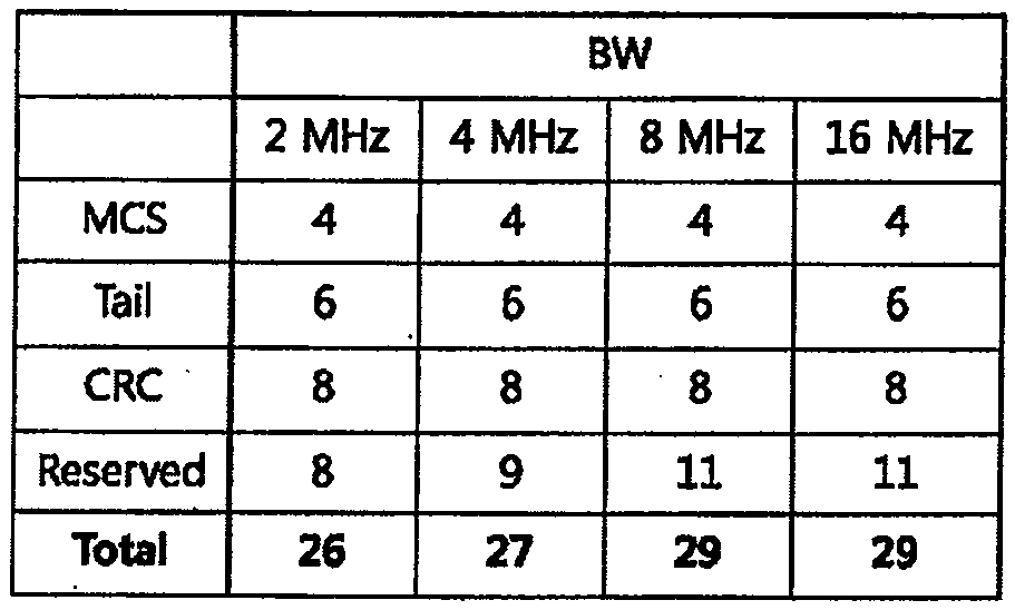
상기 표 2에서 MCS 필드는 각각의 사용자 별로 MU 프레임 형태로 송신되는 PPDU의 MCS 값을 나타낸다.In Table 2, the MCS field indicates the MCS value of a PPDU transmitted in an MU frame format for each user.
TAIL 비트는 인코더를 0 상태로 리턴하기 위해서 이용될 수 있다.The TAIL bit can be used to return the encoder to the 0 state.
CRC(Cyclic Redundancy Check) 필드는 MU 프레임을 수신하는 STA에서의 에러 검출을 위해서 사용될 수 있다.A Cyclic Redundancy Check (CRC) field may be used for error detection in the STA receiving the MU frame.
S1G 즉시응답프레임에 대한 대역폭 선택 방안Bandwidth selection scheme for S1G immediate response frame
본 발명에서는 S1G 주파수 대역(예를 들어, 902-928 MHz)에서 동작하는 무선랜 시스템에서 즉시응답프레임(immediate response frame)에 대한 대역폭을 선택하는 방안에 대해서 제안한다.The present invention proposes a method of selecting a bandwidth for an immediate response frame in a wireless LAN system operating in an S1G frequency band (for example, 902-928 MHz).
송신 STA이 제어 프레임 또는 데이터 프레임을 송신하고, 상기 데이터 프레임을 수신한 수신 STA이 SIFS(Short Inter Frame Space) 시간 후에 응답 프레임을 상기 송신 STA으로 송신하는 경우에, 상기 응답 프레임을 즉시응답프레임이라고 칭한다.When a transmitting STA transmits a control frame or a data frame and the receiving STA receiving the data frame transmits a response frame to the transmitting STA after a short inter frame space (SIFS) time, It is called.
여기서, SIFS는 aRxRFDelay + aRxPLCPDelay + aMACProcessingDelay + aRxTxTurnaroundTimer 값으로 정해진다. aRxRFDelay는 무선 주파수 전파 지연(Radio Frequency Propagation Delay)을 의미한다. aRxPLCPDelay는 PLCP 수신 지연(Reception Delay)을 의미한다. aMACProcessingDelay는 MAC에서 이벤트 핸들링(event handling)을 위한 처리 지연(Processing Delay)을 의미한다. aRxTxTurnaroundTimer는 수신 모드(Rx 모드)에서 송신 모드(Tx 모드)로 전환하는데 필요한 턴어라운드 시간(Turnaround Time)을 의미한다.Here, SIFS is determined by aRxRFDelay + aRxPLCPDelay + aMACProcessingDelay + aRxTxTurnaroundTimer value. aRxRFDelay means Radio Frequency Propagation Delay. aRxPLCPDelay means PLCP reception delay. aMACProcessingDelay means a processing delay for event handling in the MAC. aRxTxTurnaroundTimer denotes a turnaround time required for switching from a reception mode (Rx mode) to a transmission mode (Tx mode).
즉시 응답 방식의 예시로서 다음과 같은 동작을 들 수 있다. 송신 STA이 데이터 프레임을 송신하고, 상기 데이터 프레임을 성공적으로 수신한 STA이 SIFS 시간 후에 ACK 프레임을 송신할 수 있다. 또한, 송신 STA이 RTS 프레임을 송신하고, 상기 RTS 프레임에 대한 응답으로 수신 STA이 SIFS 시간 후에 CTS 프레임을 송신할 수 있다. 또한, 송신 STA이 PS-Poll(Power Save-Poll) 프레임을 송신하고, 상기 PS-Poll 프레임에 대한 응답으로 수신 STA이 SIFS 시간 후에 ACK 프레임 또는 버퍼된 데이터 프레임을 송신할 수 있다.An example of an immediate response scheme is as follows. The transmitting STA may transmit the data frame and the STA that successfully received the data frame may transmit the ACK frame after the SIFS time. In addition, the transmitting STA may transmit the RTS frame, and the receiving STA may transmit the CTS frame after the SIFS time in response to the RTS frame. In addition, the transmitting STA may transmit a PS-Poll (Power Save-Poll) frame, and the receiving STA may transmit an ACK frame or a buffered data frame after SIFS time in response to the PS-Poll frame.
즉시 응답 방식에 대해서 ACK 과정을 예로 들어 보다 구체적으로 설명한다.The ACK process will be described in more detail as an example of the immediate response scheme.
도 13은 ACK 과정을 설명하기 위한 도면이다.13 is a diagram for explaining an ACK process.
ACK 프레임을 응답으로서 요구하는 MPDU를 송신한 후에, STA은 ACKTimeout 인터벌 동안 대기한다. 여기서, ACKTimeout은 aSIFSTime + aSlotTime + aPHY-RX-START-Delay의 값에 기초하여 결정될 수 있으며, PHY-TXEND.confirm 프리머티브의 값에서 시작한다. 여기서, aSIFSTime은 MAC과 PHY가 에어 인터페이스에서 프레임의 마지막 심볼을 수신하고, 해당 프레임을 처리하고, 에어 인터페이스 상에서 가능한한 가장 이른 응답 프레임의 첫 번째 심볼을 송신하기 위해서 요구되는 명목적(nominal) 시간을 의미한다. aSlotTime은 PIFS(point coordination function (PCF) interframe space) 및 DIFS 구간을 정의하기 위해서 MAC이 사용하는 시간 단위이다. aPHY-RX-START-Delay는 PHY-RXSTART.indication 프리머티브가 이슈(issue)되는 시점까지의 지연 시간을 의미한다. PHY-RXSTART.indication 프리머티브는, PLCP가 유효한 PLCP 헤더를 가지는 PPDU를 수신하기 시작하였음을, PHY가 로컬 MAC에게 알려주는 프리머티브이다.After transmitting an MPDU requesting an ACK frame as a response, the STA waits for the ACKTimeout interval. Here, ACKTimeout can be determined based on the value of aSIFSTime + aSlotTime + aPHY-RX-START-Delay and starts from the value of PHY-TXEND.confirm primitive. Where aSIFSTime is the nominal time required for the MAC and PHY to receive the last symbol of the frame at the air interface, process the frame, and transmit the first symbol of the earliest possible response frame on the air interface . aSlotTime is the time unit used by the MAC to define the PIFS (point coordination function (PCF) interframe space) and the DIFS interval. aPHY-RX-START-Delay means the delay time until the PHY-RXSTART.indication primitive is issued. The PHY-RXSTART.indication primitive is a primitive in which the PHY informs the local MAC that the PLCP has begun to receive a PPDU with a valid PLCP header.
도 13에서는 간략하게 ACKTimeout = SIFS + Slot Time + PHY-RX-START-Delay로 표현하였다. 즉, ACKTimeout은 데이터 프레임을 수신한 STA이 SIFS 후에 ACK 프레임을 송신하는 데에 필요한 시간이라고 할 수 있으며, Slot Time을 고려하여 계산될 수 있다.In FIG. 13, it is briefly expressed as ACKTimeout = SIFS + Slot Time + PHY-RX-START-Delay. That is, ACKTimeout is a time required for the STA receiving the data frame to transmit the ACK frame after SIFS, and can be calculated in consideration of the slot time.
Slot Time은 aCCATime + aRxTxTurnaroundTime + aAirPropagationTime + aMACProcessingDelay의 값으로 정해진다. aCCATime은 CCA 메커니즘에 따라서 매체가 점유(busy) 또는 유휴(idle) 상태인지 판정하기 위해서 매 시간 슬롯 내에서 매체에 액세스할 수 있는 최대 시간을 의미한다. aRxTxTurnaroundTimer는 수신 모드(Rx 모드)에서 송신 모드(Tx 모드)로 전환하는데 필요한 턴어라운드 시간(Turnaround Time)을 의미한다. aAirPropagationTime은 슬롯 동기화된 STA들 중에서 가장 멀리 떨어진 허용가능한 STA과의 최대 거리를 신호가 전파하는데 소요되는 시간의 2배의 시간을 의미한다. aMACProcessingDelay는 MAC에서 이벤트 핸들링(event handling)을 위한 처리 지연(Processing Delay)을 의미한다.Slot Time is set to the value of aCCATime + aRxTxTurnaroundTime + aAirPropagationTime + aMACProcessingDelay. aCCATime means the maximum time that media can be accessed in each time slot to determine if the medium is busy or idle according to the CCA mechanism. aRxTxTurnaroundTimer denotes a turnaround time required for switching from a reception mode (Rx mode) to a transmission mode (Tx mode). aAirPropagationTime represents twice the time required for the signal to propagate the maximum distance from the slot-synchronized STAs to the furthest allowable STA. aMACProcessingDelay means a processing delay for event handling in the MAC.
또한, ACKTimeout을 결정하는 요소 중에서 PHY-RX-START-Delay는 ACK 프레임과 같은 즉시응답프레임이 성공적으로 트리거(trigger)되었는지를 식별하기 위한 시간으로, 보통 PLCP 헤더의 의 SIG 필드에 대한 디코딩까지 소요되는 시간을 반영한다.Among the factors determining ACKTimeout, PHY-RX-START-Delay is a time for identifying whether an immediate response frame is successfully triggered, such as an ACK frame, usually until decoding of a SIG field of a PLCP header Time.
즉, 송신 STA이 DATA 프레임을 송신하고 수신 STA이 DATA 프레임을 성공적으로 수신하였다는 가정하에, 수신 STA으로부터 송신된 ACK 프레임의 PLCP 헤더가 송신 STA에 전달되기까지의 최대 시간이 ACKTimeout으로 사용된다고 할 수 있다.Assuming that the transmitting STA has transmitted the DATA frame and the receiving STA has successfully received the DATA frame, it is assumed that the maximum time until the PLCP header of the ACK frame transmitted from the receiving STA is transmitted to the transmitting STA is used as ACKTimeout .
ACKTimeout 인터벌 동안에 PHY-RXSTART.indication 프리머티브가 발생하지 않는 경우, STA은 상기 MPDU의 송신이 실패한 것으로 판단하고, ACKTimeout 인터벌이 만료되는 때에 백오프 과정을 작동(invoke)시킨다.If the PHY-RXSTART.indication primitive does not occur during the ACKTimeout interval, the STA determines that the transmission of the MPDU has failed and invokes the backoff procedure when the ACKTimeout interval expires.
ACKTimeout 인터벌 동안에 PHY-RXSTART.indication 프리머티브가 발생하는 경우, STA은 대응하는 PHYRXEND.indication 프리머티브를 대기하여 MPDU 송신이 성공적이었는지 여부를 판정할 수 있다. PHYRXEND.indication 프리머티브는, 현재 수신되고 있는 PSDU가 완료(complete)되었음을, PHY가 MAC에게 알려주는 프리머티브이다.If a PHY-RXSTART.indication primitive occurs during the ACKTimeout interval, the STA may wait for the corresponding PHYRXEND.indication primitive to determine whether the MPDU transmission was successful. PHYRXEND.indication The primitive is a primitive in which the PHY informs the MAC that the currently received PSDU is complete.
이러한 PHYRXEND.indication 프리머티브에 대응하는, MPDU의 수신측에 의해서 송신된 유효한 ACK 프레임이 인식(recognize)되면, 이는 성공적인 ACK인 것으로 해석된다. 이에 따라, 진행중인 특정 프레임 시퀀스에 적절한 방식에 따라서, 프레임 시퀀스가 계속되는 것이 허용되거나, 또는 재시도 없이 종료될 수 있다.If a valid ACK frame transmitted by the receiving side of the MPDU corresponding to this PHYRXEND.indication primitive is recognized, it is interpreted as a successful ACK. Thus, depending on the manner appropriate to the particular frame sequence in progress, the frame sequence may be allowed to continue, or it may be terminated without retrying.
다른 유효한 프레임을 포함하는 그 외의 프레임이 인지되면, 이는 상기 MPDU 송신의 실패로 해석된다. 이 경우, STA은 PHY-RXEND.indication 프리머티브에서 백오프 과정을 작동시켜야 하고, 상기 수신된 프레임을 처리할 수도 있다. 예외적으로, PS-Poll 프레임의 수신측에 의해서 송신된 유효한 데이퍼 프레임이 인식되는 경우, 이는 상기 PS-Poll 프레임에 대한 성공적인 ACK라고 허용될 수 있따.If another frame containing another valid frame is recognized, this is interpreted as a failure of the MPDU transmission. In this case, the STA must activate the backoff procedure in the PHY-RXEND.indication primitive and may process the received frame. Exceptionally, if a valid data frame transmitted by the receiving side of the PS-Poll frame is recognized, this may be accepted as a successful ACK for the PS-Poll frame.
요컨대, 데이터 프레임을 송신한 STA은, 상기 데이터 프레임을 수신한 STA에 의해서 송신될 ACK을 대기하면서, ACKTimeout 동안에 PHY-RXSTART.indication 프리머티브가 발생하지 않으면 실패로 간주하고 리커버리 과정(즉, 백오프 과정을 다시 수행하여 상기 데이터 프레임의 재송신을 시도하는 과정)을 수행한다.That is, the STA that has transmitted the data frame waits for the ACK to be transmitted by the STA that has received the data frame, and if the PHY-RXSTART.indication primitive does not occur during the ACKTimeout, the STA regards it as a failure and performs a recovery process Off procedure to retransmit the data frame).
도 13에서 나타내는 바와 같이, ACKTimeout 값을 결정함에 있어서 PHY-RX-START-Delay가 고려되는데, PHY-RX-START-Delay는 프레임의 채널 대역폭에 따라서 달라질 수 있다. 예를 들어, 상기 도 10과 같은 S1G 1MHz 프레임 포맷의 경우에서의 PHY-RX-START-Delay와, 상기 도 11 또는 도 12와 S1G 2MHz 이상의 프레임 포맷의 경우에서의 PHY-RX-START-Delay는 상이할 수 있다.As shown in FIG. 13, PHY-RX-START-Delay is considered in determining the ACKTimeout value, and the PHY-RX-START-Delay may vary according to the channel bandwidth of the frame. For example, the PHY-RX-START-Delay in the case of the
채널 대역폭에 따른 PHY-RX-START-Delay의 길이를 비교하기 위해서, 전술한 바와 같이, PHY-RX-START-Delay를 PLCP 헤더의 SIG 필드에 대한 디코딩까지 소요되는 시간이라고 가정한다.In order to compare the length of the PHY-RX-START-Delay according to the channel bandwidth, it is assumed that the PHY-RX-START-Delay is time required until decoding of the SIG field of the PLCP header as described above.
1MHz PPDU의 경우에는 PLCP 헤더의 STF, LTF1 및 SIG 필드는 총 14개의 OFDM 심볼로 구성된다. 하나의 OFDM 심볼에 대한 슬롯 시간을 약 40㎲라고 하면, 1MHz PPDU에 대한 PHY-RX-START-Delay는 대략 560㎲(=14×40㎲)라고 할 수 있다.In the case of 1 MHz PPDU, the STF, LTF1 and SIG fields of the PLCP header are composed of a total of 14 OFDM symbols. Assuming that the slot time for one OFDM symbol is approximately 40 占 퐏, the PHY-RX-START-Delay for 1 MHz PPDU can be approximately 560 占 퐏 (= 14 占 40 占 퐏).
한편, 2MHz 이상의 (즉, 2, 4, 8, 또는 16MHz) PPDU의 경우에는 PLCP 헤더의 STF, LTF1, SIG-A 필드는 총 6 개의 OFDM 심볼로 구성된다. 따라서, 2MHz PPDU에 대한 PHY-RX-START-Delay는 대략 240㎲(=6×40㎲)라고 할 수 있다.On the other hand, in the case of PPDUs of 2 MHz or more (i.e., 2, 4, 8, or 16 MHz), the STF, LTF1, and SIG-A fields of the PLCP header are composed of six OFDM symbols in total. Therefore, the PHY-RX-START-Delay for the 2 MHz PPDU can be approximately 240 μs (= 6 × 40 μs).
따라서, 즉시응답프레임이 1MHz PPDU로 송신되는지, 2MHz 이상 PPDU로 송신되는지에 따라서 ACKTimeout이 상이하게 설정될 필요가 있다. 예를 들어, 수신 STA에 의해서 송신되는 즉시응답프레임이 1MHz PPDU인 경우에는, 2MHz 이상의 PPDU인 경우에 비해서, 송신 STA의 ACKTimeout이 더 크게 설정되는 것이 필요하다.Therefore, ACKTimeout needs to be set differently depending on whether the immediate response frame is transmitted with 1MHz PPDU or 2MHz or higher PPDU. For example, when the immediate response frame transmitted by the receiving STA is 1 MHz PPDU, it is necessary that the ACKTimeout of the transmitting STA is set to be larger than that of the PPDU of 2 MHz or more.
만약, 즉시응답프레임의 채널 대역폭과 무관하게 고정된 하나의 ACKTimeout 값이 사용되는 경우라면, PHY-RX-START-Delay는 디폴트 값으로서 최소한 560㎲(또는 560㎲ + 지연 마진(delay margin))으로 설정되어야 한다. 이러한 경우, 수신 STA에 의해서 송신되는 즉시응답프레임이 2MHz 이상의 PPDU인 경우에는, 송신 STA이 즉시응답프레임의 SIG 필드까지 디코딩하기 위해서 필요한 560㎲을 고려하여 ACKTimeout이 설정되므로 문제가 없다. 그러나, 수신 STA에 의해서 송신되는 즉시응답프레임이 1MHz PPDU인 경우에는, 송신 STA이 즉시응답프레임의 SIG 필드까지 디코딩하기 위해서 필요한 시간 외에 불필요한 320㎲를 더 고려하여 ACKTimeout이 설정된다. 이 경우, 송신 STA이 송신 실패 이후의 리커버리 과정(또는 백오프 과정)에서 대략 320㎲ 정도의 시간 낭비 또는 불필요한 시간 지연이 발생하므로, 전체 처리율(throughput) 및 에너지 소모(energy consumption)에 있어서 비효율적인 문제가 발생한다.If a fixed ACK Timeout value is used irrespective of the channel bandwidth of the immediate response frame, the PHY-RX-START-Delay defaults to at least 560 μs (or 560 μs + delay margin) Should be set. In this case, when the immediate response frame transmitted by the receiving STA is a PPDU of 2 MHz or more, there is no problem since ACKTimeout is set considering 560 필요한 necessary for decoding the SIG field of the response frame immediately by the transmitting STA. However, when the immediate response frame transmitted by the receiving STA is a 1 MHz PPDU, ACKTimeout is set considering the unnecessary 320 占 퐏 in addition to the time required for the transmitting STA to decode the SIG field of the immediate response frame immediately. In this case, since the transmission STA has a waste time of about 320 microseconds or an unnecessary time delay in the recovery process (or the backoff process) after the transmission failure, it is inefficient in overall throughput and energy consumption A problem arises.
참고로, 백오프 과정에서 하나의 백오프 슬롯 시간이 52㎲라고 가정하면, 320㎲의 불필요한 오버헤드는 백오프 타이머(또는 백오프 카운트 값) 상에서 6만큼의 차이에 해당하므로, 실제 STA의 채널 액세스 효율성의 관점에서는 매우 큰 시간 지연이라고 할 수 있다.For reference, assuming that one backoff slot time is 52 占 퐏 in the backoff process, the unnecessary overhead of 320 占 퐏 corresponds to a difference of 6 on the backoff timer (or the backoff count value) From a viewpoint of access efficiency, it can be said that there is a very large time delay.
따라서, 본 발명에서는 2 이상의 타입의 채널 대역폭을 지원하는 시스템에서 즉시응답프레임의 채널 대역폭 선택 방안과, 이에 기초한 즉시 응답 과정을 제안한다.Accordingly, the present invention proposes a channel bandwidth selection method of an immediate response frame in a system supporting two or more types of channel bandwidths, and an immediate response procedure based on the method.
본 발명에서 2 이상의 타입의 채널 대역폭을 지원한다는 것은, 동일한 MCS를 가정하였을 때, 각각의 채널 대역폭에 대해서 단위 시간(예를 들어, 하나의 OFDM 심볼 길이) 동안에 송신될 수 있는 정보 비트가 상이하다는 것을 의미한다. 또는, 각각의 채널 대역폭에 대해서 단위 시간(예를 들어, 하나의 OFDM 심볼 길이)의 듀레이션이 동일한 것을 의미한다. 따라서, 20MHz의 채널 대역폭을 1/10로, 또는 1/20로 다운-클록킹(down-clocking)하는 경우는 2 이상의 타입의 채널 대역폭을 지원하는 것에 포함되지 않는다.Supporting two or more types of channel bandwidth in the present invention means that the information bits that can be transmitted during a unit time (for example, one OFDM symbol length) are different for each channel bandwidth when the same MCS is assumed . Or, it means that the duration of unit time (for example, one OFDM symbol length) is the same for each channel bandwidth. Thus, down-clocking the channel bandwidth of 20 MHz to 1/10 or 1/20 is not included in supporting more than one type of channel bandwidth.
또한, 본 발명에서 즉시응답프레임을 트리거하는 프레임을 즉시트리거프레임(immediate trigger frame)이라고 칭한다. 즉시트리거프레임으로는, 전술한 예시에서와 같이, 정상(normal) ACK 정책을 가지는 데이터 프레임, RTS 프레임, PS-Poll 프레임 등을 예로 들 수 있다, 이 경우, 즉시응답프레임은, ACK 프레임, CTS 프레임, 데이터 프레임 등에 해당할 수 있다.In the present invention, a frame that triggers an immediate response frame is referred to as an immediate trigger frame. As an immediate trigger frame, a data frame, a RTS frame, a PS-Poll frame or the like having a normal ACK policy can be exemplified. In this case, the immediate response frame includes an ACK frame, a CTS Frames, data frames, and the like.
즉시트리거프레임을 송신하는 STA은, 즉시트리거프레임의 송신을 마친 시점에서부터 즉시응답타이머(immediate response timer)를 설정할 수 있다. 즉, 송신 STA은 즉시트리거프레임에 대한 송신을 마친 후, PHY-TXEND.confirm 프리머티브가 발생한 시점에부터 시작해서, aSIFSTime + aSlotTime + aPHY-RX-START-Delay 시간 동안 즉시응답타이머를 동작시킬 수 있다.An STA that immediately transmits a trigger frame can immediately set an immediate response timer from the moment the transmission of the trigger frame is completed. That is, the transmitting STA immediately starts to transmit an immediate response timer during aSIFSTime + aSlotTime + aPHY-RX-START-Delay time, starting from the time when the PHY-TXEND.confirm primitive is generated, .
즉시응답타이머에서 타임아웃(timeout)이 발생하기 전까지 PHY-RXSTART.indication 프리머티브가 발생하지 않는 경우, 송신 STA은, 수신 STA로부터 즉시응답프레임이 송신되지 않은 것으로 간주하고 리커버리 과정(또는 백오프 과정)을 수행할 수 있다.If the PHY-RXSTART.indication primitive does not occur before a timeout occurs in the immediate response timer, the transmitting STA regards that the immediate response frame is not transmitted from the receiving STA and the recovery process (or backoff Process) can be performed.
즉시트리거프레임은, 전술한 바와 같이, 채널 대역폭에 따라 서로 다른 PHY-RX-START-Delay 값을 가지는 2개 이상의 PPDU 형태 중 하나로 송신된다.The immediate trigger frame is transmitted in one of two or more PPDU types having different PHY-RX-START-Delay values depending on the channel bandwidth, as described above.
예를 들어, 제 1 채널 대역폭(예를 들어, 1MHz)을 사용하는 PPDU는 PHY-RX-START-Delay 값으로 A를 가지고, 제 2 채널 대역폭, 제 3 채널 대역폭 등(예를 들어, 2MHz, 4MHz, 등)을 사용하는 PPDU는 PHY-RX-START-Delay 값으로 B를 가진다고 가정한다. 여기서, A와 B는 상이한 값으로 설정되고, A가 B보다 큰 것으로 가정한다.For example, a PPDU using a first channel bandwidth (e.g., 1 MHz) may have a PHY-RX-START-Delay value of A and may have a second channel bandwidth, a third channel bandwidth, 4 MHz, etc.) is assumed to have B as the PHY-RX-START-Delay value. Here, it is assumed that A and B are set to different values, and A is larger than B.
본 발명에 따르면, 이는 수신 STA의 입장에서 즉시응답프레임으로 사용할 PPDU를 기준으로 하여 결정되는 PHY-RX-START-Delay 값이, 수신된 즉시트리거프레임의 PPDU를 기준으로 하여 결정되는 PHY-RX-START-Delay 값과 동일하거나 그보다 작은 값을 가지도록, 상기 즉시응답프레임으로 사용할 PPDU의 채널 대역폭이 결정되어야 한다.According to the present invention, the PHY-RX-START-Delay value determined on the basis of the PPDU to be used as the immediate response frame in the receiving STA is determined based on the PPDU of the trigger frame immediately after being received. The channel bandwidth of the PPDU to be used as the immediate response frame should be determined so as to have a value equal to or smaller than the START-Delay value.
예를 들어, 송신 STA이 제 1 채널 대역폭을 사용해 즉시트리거프레임을 송신한 경우, 수신 STA은 즉시응답프레임을 송신할 때 제 1 채널 대역폭을 사용해 응답할 수 있다.For example, if the transmitting STA immediately transmits the trigger frame using the first channel bandwidth, the receiving STA may respond using the first channel bandwidth when transmitting the acknowledgment frame immediately.
또한, 송신 STA이 제 2 채널 대역폭 또는 제 3 채널 대역폭을 사용해 즉시트리거프레임을 송신한 경우, 수신 STA은 즉시응답프레임을 송신할 때 제 1 채널 대역폭을 사용해서 응답해서는 안 된다. 수신 STA의 입장에서는, 즉시응답프레임으로 사용할 PPDU를 기준으로 하여 결정되는 PHY-RX-START-Delay 값이, 수신된 즉시트리거프레임의 PPDU를 기준으로 하여 결정되는 PHY-RX-START-Delay 값인 B와 동일하거나 B 보다 작은 값을 가지도록, 상기 즉시응답프레임으로 사용할 PPDU의 채널 대역폭이 결정되어야 하기 때문이다. 만약 송신 STA이 제 2 채널 대역폭 또는 제 3 채널 대역폭을 사용해 즉시트리거프레임을 수신한 경우에, 제 2 채널 대역폭 또는 제 3 채널 대역폭의 PPDU를 사용하여 즉시응답프레임을 송신하는 경우라면 PHY-RX-START-Delay 값은 B와 동일하므로 문제 없고, 제 1 채널 대역폭의 PPDU를 사용하여 즉시응답프레임을 송신하는 경우라면 PHY-RX-START-Delay 값이 A가 되어 B 보다 크기 때문이다.Also, if the transmitting STA immediately transmits the trigger frame using the second channel bandwidth or the third channel bandwidth, the receiving STA should not respond using the first channel bandwidth when transmitting the acknowledgment frame immediately. In the receiving STA, the PHY-RX-START-Delay value determined based on the PPDU to be used as the immediate response frame is the PHY-RX-START-Delay value determined based on the PPDU of the trigger frame immediately after being received The channel bandwidth of the PPDU to be used as the immediate response frame must be determined so as to have a value equal to or smaller than B, If the transmitting STA immediately receives the trigger frame using the second channel bandwidth or the third channel bandwidth, if the immediate response frame is transmitted using the PPDU of the second channel bandwidth or the third channel bandwidth, the PHY-RX- Since the START-Delay value is equal to B, if the immediate response frame is transmitted using the PPDU of the first channel bandwidth, the value of PHY-RX-START-Delay becomes A and is larger than B.
추가적으로, 동일한 PHY-RX-START-Delay 값을 가지는 채널 대역폭(예를 들어, 제 2 채널 대역폭, 제 3 채널 대역폭 등)의 PPDU를 사용하여 즉시응답프레임이 송신되는 경우, 즉시응답프레임의 채널 대역폭은 즉시트리거프레임의 채널 대역폭과 같거나 또는 그보다 작아야 한다.Additionally, when an immediate response frame is transmitted using a PPDU of a channel bandwidth having the same PHY-RX-START-Delay value (e.g., a second channel bandwidth, a third channel bandwidth, etc.) Must immediately be equal to or less than the channel bandwidth of the trigger frame.
수신 STA이 즉시응답프레임의 채널 대역폭을 선택함에 있어서 위와 같은 규칙에 따르는 경우, 즉시트리거프레임을 송신한 송신 STA은 즉시응답타이머의 타임아웃(immediate response timeout) 값은 aSIFSTime + aSlotTime + aPHY-RX-START-Delay 값으로 설정된다. 여기서, aPHY-RX-START-Delay 값은 송신 STA이 송신한 즉시트리거프레임의 aPHY-RX-START-Delay 값으로 설정된다. 이는, 즉시응답타임아웃 값은, 송신 STA이 송신한 즉시트리거프레임의 채널 대역폭에 따라서 달라질 수 있다는 것을 의미한다.When the receiving STA complies with the above rule in selecting the channel bandwidth of the immediate response frame, the immediate STA of the transmitting STA that immediately transmits the trigger frame has the immediate response timeout value aSIFSTime + aSlotTime + aPHY-RX- It is set to the START-Delay value. Here, the aPHY-RX-START-Delay value is set to aPHY-RX-START-Delay value of the trigger frame immediately after transmission STA transmits. This means that the immediate response timeout value can vary according to the channel bandwidth of the trigger frame as soon as the transmitting STA has transmitted.
본 발명에서 정의하는 즉시 응답 과정을 S1G 무선랜 시스템(또는 IEEE 802.11ah 표준에 따르는 시스템)에 적용하는 경우의 예시에 대해서 이하에서 설명한다.An example in which the instant response procedure defined in the present invention is applied to the S1G wireless LAN system (or a system conforming to the IEEE 802.11ah standard) will be described below.
ACK 프레임을 응답으로서 요구하는 MPDU를 송신한 후에, STA은 ACKTimeout 인터벌 동안 대기한다. 여기서, ACKTimeout은 aSIFSTime + aSlotTime + aPHY-RX-START-Delay의 값에 기초하여 결정될 수 있고, PHY-TXEND.confirm 프리머티브의 값에서 시작한다.After transmitting an MPDU requesting an ACK frame as a response, the STA waits for the ACKTimeout interval. Here, ACKTimeout can be determined based on the value of aSIFSTime + aSlotTime + aPHY-RX-START-Delay and starts from the value of PHY-TXEND.confirm primitive.
여기서, aPHY-RX-START-Delay는 TXVECTOR의 CH_BANDWIDTH(또는 프리앰블 타입) 파라미터에 의해서 결정된다. TXVECTOR의 CH_BANDWIDTH 파라미터가 (중복된(duplicated))1MHz에 해당하는 경우, aPHY-RX-START-Delay는 601㎲ 으로 설정된다. TXVECTOR의 CH_BANDWIDTH 파라미터가 중복된(duplicated) 2MHz/4MHz/8MHz/16MHz에 해당하는 경우, aPHY-RX-START-Delay는 281㎲ 으로 설정된다.Here, aPHY-RX-START-Delay is determined by the CH_BANDWIDTH (or preamble type) parameter of the TXVECTOR. If the CH_BANDWIDTH parameter of the TXVECTOR corresponds to 1 MHz (duplicated), aPHY-RX-START-Delay is set to 601 μs. If the CH_BANDWIDTH parameter of the TXVECTOR corresponds to a duplicated 2 MHz / 4 MHz / 8 MHz / 16 MHz, aPHY-RX-START-Delay is set to 281 μs.
S1G PPDU를 통해서 전달되는 프레임에 응답하는 제어 프레임(즉, 응답 프레임)을 송신하는 S1G STA은, 상기 응답 프레임을 유발(elicit)하는 프레임의 RXVECTOR 파라미터 CH_BANDWIDTH에 의해서 지시되는 채널 폭과 동일한 채널 폭을, TXVECTOR 파라미터 CH_BANDWIDTH가 지시하도록 설정할 수 있다.The S1G STA that transmits the control frame (i.e., the response frame) responding to the frame transmitted through the S1G PPDU transmits a channel width equal to the channel width indicated by the RXVECTOR parameter CH_BANDWIDTH of the frame that elicits the response frame , The TXVECTOR parameter CH_BANDWIDTH can be set to indicate.
또한, S1G STA에서, 2MHz 이상의 프리앰블(>=2MHz preamble)에 대한 응답으로서 1MHz 프리앰블을 송신하는 것은 허용되지 않는다.Also, in S1G STA, it is not allowed to transmit a 1MHz preamble in response to a preamble of 2MHz or more (> = 2MHz preamble).
도 14는 본 발명의 예시에 따른 프레임 교환 시퀀스의 허용 여부를 설명하기 위한 도면이다.14 is a diagram for explaining whether or not the frame exchange sequence according to the example of the present invention is allowed.
도 14에서는 데이터 프레임 송신 후에 ACK 프레임을 수신하는 동작을 나타내며, 도 14(a)는 허용되는 예시들을 나타내고, 도 14(b)는 허용되지 않는 예시들을 나타낸다.Fig. 14 shows an operation for receiving an ACK frame after a data frame transmission, Fig. 14 (a) showing permitted examples, and Fig. 14 (b) showing unacceptable examples.
도 14(a)에서 나타내는 바와 같이, 4MHz PPDU의 데이터 프레임 송신 이후에 중복된(duplicated) 2MHz PPDU의 ACK 프레임을 수신하는 것이 허용된다. 또한, 2MHz PPDU의 데이터 프레임 송신 이후에 2MHz PPDU의 ACK 프레임을 수신하는 것이 허용된다. 또한, 1MHz PPDU의 데이터 프레임 송신 이후에 1MHz PPDU의 ACK 프레임을 수신하는 것이 허용된다.As shown in Fig. 14 (a), it is allowed to receive an ACK frame of a duplicated 2 MHz PPDU after transmission of a data frame of 4 MHz PPDU. It is also allowed to receive an ACK frame of 2 MHz PPDU after the data frame transmission of 2 MHz PPDU. It is also allowed to receive an ACK frame of 1 MHz PPDU after transmission of a data frame of 1 MHz PPDU.
한편, 도 14(b)에서 나타내는 바와 같이, 4MHz PPDU의 데이터 프레임 송신 이후에 중복된(duplicated) 1MHz PPDU의 ACK 프레임을 수신하는 것은 허용되지 않는다. 또한, 2MHz PPDU의 데이터 프레임 송신 이후에 중복된(duplicated) 1MHz PPDU의 ACK 프레임을 수신하는 것은 허용되지 않는다.On the other hand, as shown in FIG. 14 (b), it is not allowed to receive an ACK frame of a duplicated 1 MHz PPDU after the data frame transmission of the 4 MHz PPDU. Also, it is not allowed to receive an ACK frame of a 1MHz PPDU that is duplicated after a data frame transmission of a 2MHz PPDU.
2MHz 또는 4MHz 채널 대역폭의 데이터 프레임을 송신한 STA은, 이에 대한 응답 프레임으로서 2MHz 채널 대역폭의 프리앰블을 가지는 PPDU를 기대하고, aPHY-RX-START-Delay을 대략 281㎲ 로 간주하여 타임아웃을 값을 계산하고, 이에 따라 응답 프레임의 수신 및 처리를 수행하게 된다.The STA that has transmitted the data frame of the 2MHz or 4MHz channel bandwidth expects the PPDU having the preamble of the 2MHz channel bandwidth as a response frame to it, and regards the aPHY-RX-START-Delay as about 281μs to calculate the timeout value And performs reception and processing of the response frame accordingly.
만약, 도 14(b)와 같이 2MHz 또는 4MHz 채널 대역폭의 데이터 프레임에 응답하여, 1MHz 채널 대역폭의 프리앰블을 가지는 PPDU의 응답 프레임이 수신되면, 이러한 응답 프레임을 올바르게 디코딩하기 위한 타임아웃 값은 대략 601㎲의 aPHY-RX-START-Delay에 기초하여 계산되어야 하는데 반하여, 송신 STA은 대략 281㎲의 aPHY-RX-START-Delay에 기초하여 타임아웃 값을 계산하고 응답 프레임의 수신 및 처리를 수행하므로, 응답 프레임을 올바르게 수신할 수 없다.If a response frame of a PPDU having a preamble of 1 MHz channel bandwidth is received in response to a data frame of 2 MHz or 4 MHz channel bandwidth as shown in FIG. 14 (b), the timeout value for correctly decoding this response frame is approximately 601 RX-START-Delay of about 281 mu s, whereas the transmitting STA calculates the timeout value based on aPHY-RX-START-Delay of approximately 281 mu s and performs reception and processing of the response frame, Response frames can not be received correctly.
전술한 본 발명의 다양한 예시들에서 aPHY-RX-START-Delay에 대한 601㎲, 281㎲와 같은 값들은 단지 예시적인 것이며 설명의 명료성을 위한 것일 뿐이다. 따라서, 본 발명의 범위가 이러한 특정 수치에 제한되는 것은 아니다.In the various examples of the present invention described above, values such as 601 [mu] s and 281 [mu] s for aPHY-RX-START-Delay are merely illustrative and are for clarity of explanation only. Therefore, the scope of the present invention is not limited to these specific numerical values.
VCS 메커니즘VCS mechanism
CS(Carrier Sense) 메커니즘은 채널 액세스를 위해서 이용되며, 해당 채널의 점유/유휴(busy/idle) 상태를 결정하기 위한 동작을 의미한다.The Carrier Sense (CS) mechanism is used for channel access and refers to an operation for determining a busy / idle state of a corresponding channel.
기존의 NAV 설정 방식은 어떤 STA이 다른 STA으로부터 수신한 프레임의 듀레이션 필드의 값에 기초하여, 소정의 기간 동안 상기 다른 STA에 의해서 채널이 사용중인 것으로 결정하고, 이에 따라 동작(즉, 상기 소정의 기간 동안 매체 액세스를 시도하지 않음)하는 것을 의미한다. 이러한 동작은, 물리적(physical) CS를 수행하여 해당 매체가 점유중인지 여부를 결정하는 것에 비교하여, (물리적으로 해당 매체가 유휴 상태이더라도) 마치 CS를 수행한 결과 해당 매체가 점유중인 것으로 결정하는 것과 같다고 하여, 가상(virtual) CS 메커니즘(VCS mechanism)이라고 칭할 수 있다.The existing NAV setting scheme determines that the channel is being used by the other STA for a predetermined period based on the value of the duration field of a frame received from another STA by an STA, And does not attempt to access the medium for a period of time). This operation is equivalent to determining that the corresponding medium is occupied as a result of performing CS (even when the corresponding medium is physically idle) as compared with determining whether the corresponding medium is occupied by performing a physical CS , It can be referred to as a virtual CS mechanism (VCS mechanism).
예를 들어, 수신한 프레임의 목적지(destination) STA이 아닌 서드파티(3rd party) STA들은, 수신한 프레임에 대한 CRC 값이 유효하지 않은 경우에는 에러가 있는 것으로 간주한다. 에러가 있는 프레임을 수신한 STA들은 EIFS(Extended Inter-Frame Space) 시간 동안 기다린 후에, 채널이 유휴상태이면 백오프 과정을 재개하게 된다. EIFS는 일반적으로, aSIFSTime + DIFS + ACKTxTime에 기초하여 계산된다.For example, if it is not the destination of the received frame (destination) STA third party (3 rd party) are STA, the CRC value for the received frame that are not valid are to be considered to be in error. The STAs that received the erroneous frame wait for the Extended Inter-Frame Space (EIFS) time and resume the backoff process if the channel is idle. EIFS is generally calculated based on aSIFSTime + DIFS + ACKTxTime.
여기서, ACKTxTime은 STA이 ACK 프레임을 송신하기 위해서 요구되는 시간을 의미한다. 전술한 본 발명에서 제안하는 응답 프레임의 대역폭 선택 방안에 따르면, ACK 프레임의 채널 대역폭은 ACK 프레임을 유발하는 프레임(예를 들어, 즉시트리거프레임)의 채널 대역폭에 따라서 결정된다. 예를 들어, 즉시트리거프레임이 2MHz 이상의 프리앰블 타입을 가지는 경우, 즉시응답프레임은 1MHz 프리앰블 타입을 가지는 것이 허용되지 않는다. 또한, 즉시응답프레임의 프리앰블 채널 대역폭 타입은, 즉시트리거프레임의 프리앰블 채널 대역폭 타입과 동일하게 설정된다.Here, ACKTxTime means a time required for an STA to transmit an ACK frame. According to the bandwidth selection method of the response frame proposed in the present invention, the channel bandwidth of the ACK frame is determined according to the channel bandwidth of a frame (for example, an immediate trigger frame) causing an ACK frame. For example, if the immediate trigger frame has a preamble type of 2 MHz or more, the immediate response frame is not allowed to have a 1 MHz preamble type. In addition, the preamble channel bandwidth type of the immediate response frame is set to be the same as the preamble channel bandwidth type of the immediate trigger frame immediately.
이에 따라, 서드파티 STA들이 에러가 있는 프레임을 수신하면, EIFS 시간 동안 채널 액세스를 연기(defer)하기 위해, 수신한 프레임의 채널 대역폭을 확인해야 한다. 제 1 채널 대역폭을 통해 수신한 PPDU에 대해서 에러가 발생한 경우, EIFS의 ACKTxTime은 제 1 채널 대역폭과 동일한 채널 대역폭에 대한 aPHY-RX-START-Delay 값을 가정하여 계산된다 (전술한 바와 같이, aPHY-RX-START-Delay는 ACK 프레임과 같은 즉시응답프레임이 성공적으로 트리거되었는지를 식별하기 위한 시간으로, 보통 PLCP 헤더의 SIG 필드에 대한 디코딩까지 소요되는 시간을 반영한다).Accordingly, when third-party STAs receive an erroneous frame, they must check the channel bandwidth of the received frame to defer the channel access during EIFS time. If an error occurs for the PPDU received through the first channel bandwidth, ACKTxTime of EIFS is calculated assuming aPHY-RX-START-Delay value for the same channel bandwidth as the first channel bandwidth (as described above, aPHY -RX-START-Delay is a time for identifying whether an immediate response frame, such as an ACK frame, was successfully triggered, and usually reflects the time taken to decode the SIG field of the PLCP header.
이는, 상기 제 1 채널 대역폭을 통해 수신한 PPDU에 대한 ACK 프레임도 동일하게 제 1 채널 대역폭을 사용해서 송신되며, 해당 ACK 프레임에 대해서는 제 1 채널 대역폭에 대한 aPHY-RX-START-Delay 값이 적용되어야 하기 때문이다. 만약, 제 1 채널 대역폭이 아닌 제 2 채널 대역폭 또는 제 3 채널 대역폭 등을 통해 수신한 PPDU에 대해서 에러가 발생한 경우, EIFS의 ACKTxTime은 제 2 채널 대역폭 또는 제 3 채널 대역폭에 대한 aPHY-RX-START-Delay 값을 가정하여 계산된다.The aPHY-RX-START-Delay value for the first channel bandwidth is applied to the ACK frame for the ACK frame for the PPDU received through the first channel bandwidth using the first channel bandwidth, . If an error occurs in the PPDU received through the second channel bandwidth or the third channel bandwidth instead of the first channel bandwidth, the ACKTxTime of the EIFS is aPHY-RX-START for the second channel bandwidth or the third channel bandwidth -Delay value.
수신한 프레임의 목적지 STA이 아닌 서드파티 STA들은, 수신한 프레임에 대한 CRC 값이 유효한 경우에는 에러가 없는 것으로 간주한다. 에러가 없는 프레임을 수신한 STA들은 수신된 프레임의 MAC 헤더에 포함된 듀레이션 필드(duration field)가 지시하는 값에 해당하는 시간만큼 NAV를 설정한다. 어떤 프레임에 MAC 헤더의 듀레이션 필드는 후속하여 송신될 프레임(들)을 보호하기 위한 프레임 송신 시간을 나타내는 값으로 설정된다.Third party STAs that are not the destination STAs of the received frame are considered to have no error if the CRC value for the received frame is valid. The STAs that receive the frame with no error set the NAV for a time corresponding to the value indicated by the duration field included in the MAC header of the received frame. In a certain frame, the duration field of the MAC header is set to a value indicating a frame transmission time for protecting the frame (s) to be subsequently transmitted.
한편, 짧은 MAC 프레임과 같은 경우에는 MAC 헤더에 대한 오버헤드를 줄이기 위해서, 듀레이션 필드가 MAC 헤더에 포함되지 않는다. 따라서, 전술한 바와 같이 듀레이션 필드를 이용하여 NAV를 설정하는 방식이 적용될 수 없다.On the other hand, in the case of a short MAC frame, in order to reduce the overhead on the MAC header, the duration field is not included in the MAC header. Therefore, the method of setting the NAV using the duration field can not be applied as described above.
짧은 MAC 프레임을 수신하거나 또는 정상적인 MAC 프레임을 수신하는 어떤 경우라도, STA이 NAV 값을 올바르게 설정하도록 하기 위해서는, 후속하여 송신되는 프레임(들)에 대한 정보가 MAC 헤더가 아닌 다른 부분을 통해서 전달될 필요가 있다.In either case of receiving a short MAC frame or receiving a normal MAC frame, in order for the STA to correctly set the NAV value, information about the frame (s) to be subsequently transmitted is transmitted through a part other than the MAC header There is a need.
기존과 같이 수신 프레임의 듀레이션 필드에 기초하여 NAV 값을 설정하는 VCS 메커니즘과 달리, 본 발명에서 제안하는 VCS 메커니즘은 듀레이션 필드가 아닌 다른 특정 정보에 기초하여 동작한다. 따라서, 본 발명에서 제안하는 바에 따라서 수신 프레임의 특정 정보에 기초하여 설정되는 값(즉, 기존의 NAV 값과 유사한 목적으로 설정되는 값)을 VCS의 결과로 채널이 사용 중인 것으로 결정되는 시간 기간이라는 의미에서, "VCS 시간 길이 값"이라고 칭한다. 그러나, 본 발명에서 제안하는 VCS 시간 길이 값의 개념이, 듀레이션 필드가 아닌 다른 정보에 기초하여 NAV 값을 설정하는 것을 배제하는 것은 아니다.Unlike the conventional VCS mechanism for setting the NAV value based on the duration field of the received frame, the VCS mechanism proposed in the present invention operates based on specific information other than the duration field. Therefore, according to the proposal of the present invention, the value set based on the specific information of the received frame (i.e., the value set for the purpose similar to the existing NAV value) is a time period in which it is determined that the channel is being used as a result of the VCS Quot; VCS time length value ". However, the concept of the VCS time length value proposed in the present invention does not exclude the setting of the NAV value based on information other than the duration field.
예를 들어, 어떤 프레임의 PLCP SIG 필드 내의 응답 프레임 타입(response frame type) 필드(이 필드는 ACK 지시(ACK indication) 파라미터, 응답 지시(response indication) 파라미터라고 칭할 수도 있음)를 이용하여, NAV 값(또는 VCS 시간 길이 값)을 설정할 수 있다. 예를 들어, 어떤 프레임의 응답 프레임 타입 파라미터가 지시하는 바에 따라, 상기 프레임에 후속하는 프레임의 타입이 무엇인지 알 수 있으므로, 이에 기초하여 만약 상기 프레임에 듀레이션 필드가 있다면 그 값이 무엇일지를 가정하고, 이에 기초하여 NAV 값(또는 VCS 시간 길이 값)을 결정한다고 표현할 수도 있다. 물론, 반드시 듀레이션 필드의 값을 예상/가정하는 것이 요구되는 것은 아니며, 이는 단지 기존의 NAV 설정 메커니즘과 비교하여 본 발명의 제안에 대한 이해를 돕기 위한 것이다.For example, using a response frame type field (this field may be referred to as an ACK indication parameter, a response indication parameter) in a PLCP SIG field of a frame, the NAV value (Or VCS time length value) can be set. For example, based on the response frame type parameter of a certain frame, it is possible to know what type of frame subsequent to the frame is, and accordingly, if there is a duration field in the frame, And determines the NAV value (or the VCS time length value) on the basis thereof. Of course, it is not necessary to necessarily anticipate / assume the value of the duration field, but this is only to aid understanding of the proposal of the present invention in comparison with the existing NAV setting mechanism.
응답 프레임 타입 파라미터는, 응답 없음(No Response), NDP 제어 응답(NDP Control Response), 정상 제어 응답(Normal Control Response), 긴 응답(Long Response) 등의 타입들 중에서 하나를 지시하도록 설정될 수 있다.The response frame type parameter may be set to indicate one of the types such as No Response, NDP Control Response, Normal Control Response, and Long Response .
도 15는 PLCP 헤더의 SIG 필드의 응답 프레임 타입 필드를 사용하는 본 발명의 예시를 설명하기 위한 도면이다.15 is a diagram for explaining an example of the present invention using the response frame type field of the SIG field of the PLCP header.
도 15의 예시에서 DATA 프레임에 후속하여 송신되는 ACK 프레임의 타입에 따라서, DATA 프레임의 PLCP 헤더의 SIG 필드에 포함된 정보 중에서 응답 프레임 타입 필드(또는 응답 지시 파라미터)는 No Response, NDP Control Response, Normal Control Response, 또는 Long Response 중에서 어느 하나를 지시하는 값으로 설정될 수 있다.15, the response frame type field (or response response parameter) among the information contained in the SIG field of the PLCP header of the DATA frame is No Response, NDP Control Response, Normal Control Response, or Long Response.
응답 프레임 타입이 No Response인 경우, 수신한 프레임의 MAC 헤더의 Duration 필드의 값이, 만약 존재한다면, 0의 값을 가질 것으로 예상/가정할 수 있다. 따라서, 응답 지시 파라미터의 값이 No Response를 지시하면, NAV 값(또는 VCS 시간 길이 값)이 0으로 설정된다.If the response frame type is No Response, the value of the Duration field of the MAC header of the received frame may be assumed / assumed to have a value of 0, if present. Therefore, if the value of the response indication parameter indicates No Response, the NAV value (or VCS time length value) is set to zero.
응답 프레임 타입이 NDP Control Response인 경우, 수신한 프레임의 MAC 헤더의 Duration 필드 값이, 만약 존재한다면, PLCP 헤더 송신 시간 + SIFS (PLCP header transmission time plus SIFS)의 값을 가질 것으로 예상/가정할 수 있다. NDP 프레임은 PLCP 헤더만으로 구성된 프레임을 의미하므로, PLCP 헤더 송신 시간은 NDP 프레임 송신 시간(즉, NDPTxTime)이라고 표현할 수도 있다. 따라서, 응답 지시 파라미터의 값이 NDP Control Response를 지시하면, NAV 값(또는 VCS 시간 길이 값)이 NDPTxTime + aSIFSTime으로 설정된다.If the response frame type is NDP Control Response, the Duration field value of the MAC header of the received frame may be expected to have a value of PLCP header transmission time plus SIFS, if present. have. Since the NDP frame is a frame composed only of the PLCP header, the PLCP header transmission time may be expressed as an NDP frame transmission time (i.e., NDPTxTime). Therefore, if the value of the response indication parameter indicates the NDP Control Response, the NAV value (or VCS time length value) is set to NDPTxTime + aSIFSTime.
응답 프레임 타입이 Normal Control Response인 경우, 수신한 프레임의 MAC 헤더의 Duration 필드의 값이, 만약 존재한다면, CTS/ACK/블록 ACK 송신 시간 + SIFS (CTS/ACK/BlockACK transmission Time plus SIFS)의 값을 가질 것으로 예상/가정할 수 있다. CTS/ACK/BlockACK 프레임 송신은 정상 프레임에 해당하므로, CTS/ACK/블록 ACK 송신 시간은 정상 프레임 송신시간(즉, NoramlTxTime)이라고 표현할 수도 있다. 따라서, 응답 지시 파라미터의 값이 Noral Control Response를 지시하면, NAV 값(또는 VCS 시간 길이 값)이 NormalTxTime + aSIFSTime으로 설정된다.If the response frame type is the Normal Control Response, the value of the Duration field of the MAC header of the received frame, if present, is the value of the CTS / ACK / Block ACK transmission time + SIFS (CTS / ACK / BlockACK transmission Time plus SIFS) / RTI > < / RTI > Since CTS / ACK / BlockACK frame transmission corresponds to a normal frame, the CTS / ACK / block ACK transmission time may be expressed as a normal frame transmission time (i.e., NoramlTxTime). Therefore, if the value of the response indication parameter indicates the Noral Control Response, the NAV value (or VCS time length value) is set to NormalTxTime + aSIFSTime.
응답 프레임 타입이 Long Response인 경우, 수신한 프레임의 MAC 헤더의 Duration 필드 값이, 만약 존재한다면, 임의의 응답 프레임을 나타내기 위해 최대 PPDU 송신 시간 + SIFS (MAX_PPDU transmission Time plus SIFS) 의 값을 가질 것으로 예상/가정할 수 있다. 따라서, 응답 지시 파라미터의 값이 Long Response를 지시하면, NAV 값(또는 VCS 시간 길이 값)이 MaxPPDUTxTime + aSIFSTime으로 설정된다.If the response frame type is Long Response, the Duration field value of the MAC header of the received frame, if present, has the value of the maximum PPDU transmission time + SIFS (MAX_PPDU transmission Time plus SIFS) to indicate an arbitrary response frame Expected / assumed. Therefore, if the value of the response indication parameter indicates a Long Response, the NAV value (or VCS time length value) is set to MaxPPDUTxTime + aSIFSTime.
위와 같이 수신된 프레임에 포함된 응답 프레임 타입 정보를 통하여, 후속하여 송신될 프레임의 타입을 예상/가정할 수 있지만, 서드파티 STA가 올바르게 NAV 값(또는 VCS 시간 길이 값)를 설정하기 위해서는 응답 프레임의 송신 시간 길이를 결정하여야 한다. 전술한 바와 같이 어떤 프레임의 송신 시간은 채널 대역폭에 따라서 상이하기 때문이다.It is possible to predict / presume the type of the frame to be subsequently transmitted through the response frame type information included in the received frame. However, in order for the third party STA to correctly set the NAV value (or the VCS time length value) The length of the transmission time of the mobile station. As described above, the transmission time of a certain frame differs depending on the channel bandwidth.
구체적으로, 서드파티 STA이 NAV 값(또는 VCS 시간 길이 값)를 설정하기 위해서, 응답 프레임의 MPDU 부분의 송신 시간 길이와 프리앰블 부분의 송신 시간 길이가 올바르게 결정되어야 한다.Specifically, in order for the third party STA to set the NAV value (or the VCS time length value), the transmission time length of the MPDU portion of the response frame and the transmission time length of the preamble portion must be correctly determined.
응답 프레임의 MPDU 부분의 송신 시간 길이는, 수신된 프레임의 PLCP SIG 필드의 응답 프레임 타입에 기초하여 결정된다. 예를 들어, 응답 프레임 타입이 No Response, NDP Control Response, Normal Control Response, 또는 Long Response 중의 어느 하나를 지시하는 경우 그에 따른 MPDU 값이 결정된다.The transmission time length of the MPDU portion of the response frame is determined based on the response frame type of the PLCP SIG field of the received frame. For example, if the response frame type indicates any of No Response, NDP Control Response, Normal Control Response, or Long Response, the MPDU value is determined accordingly.
응답 프레임의 프리앰블 부분의 송신 시간 길이는, 채널 대역폭에 의해서 결정된다. 예를 들어, 1MHz 채널 대역폭의 프리앰블 타입의 경우와, 2MHz 이상의 채널 대역폭의 프리앰블 타입의 경우에서, 응답 프레임의 프리앰블 부분의 시간 길이가 상이하게/별개로 결정된다(상기 도 10 내지 12 참조). 또한, 응답 프레임의 채널 대역폭은, 서드파티 STA이 수신한 프레임의 채널 대역폭에 의해서 결정된다.The transmission time length of the preamble portion of the response frame is determined by the channel bandwidth. For example, in the case of the preamble type of the 1 MHz channel bandwidth and the case of the preamble type of the channel bandwidth of 2 MHz or more, the time length of the preamble portion of the response frame is determined differently / separately (see FIGS. 10 to 12). The channel bandwidth of the response frame is determined by the channel bandwidth of the frame received by the third party STA.
결과적으로, 서드파티 STA가 설정하는 NAV 값(또는 VCS 시간 길이 값)은, 응답 프레임의 채널 대역폭(또는 수신된 프레임의 채널 대역폭에 따라서 결정되는 응답 프레임의 프리앰블 타입), 및 상기 수신된 프레임의 PLCP 헤더에 포함된 응답 프레임 타입 필드의 값(또는 응답 지시 파라미터 값)에 의해서 결정된다. 동일한 의미를 달리 표현하자면, 서드파티 STA이 수신한 프레임의 PLCP 헤더에 포함된 응답 프레임 타입 필드의 값(또는 응답 지시 파라미터 값)에 기초하여 응답 프레임 타입이 결정되고, 해당 응답 프레임 타입에 있어서의 프리앰블의 길이/타입은 수신된 프레임의 채널 대역폭에 의하여 결정되며, 이에 기초하여 결정되는 응답 프레임의 송신에 필요한 시간을 포함하여 NAV 값(또는 VCS 시간 길이 값)이 결정될 수 있다. 이에 따라, 서드파티 STA은 수신되는 프레임 종류(예를 들어, 짧은 MAC 프레임 또는 그 외의 프레임(즉, 듀레이션 필드가 없거나 듀레이션 필드가 존재하는 경우)에 대한 구분 없이, NAV 값(또는 VCS 시간 길이 값)을 올바르게 설정할 수 있게 된다.As a result, the NAV value (or VCS time length value) set by the third party STA is determined by the channel bandwidth of the response frame (or the preamble type of the response frame determined according to the channel bandwidth of the received frame) (Or response indication parameter value) of the response frame type field included in the PLCP header. In other words, the response frame type is determined based on the value (or the response indication parameter value) of the response frame type field included in the PLCP header of the frame received by the third party STA, The length / type of the preamble is determined by the channel bandwidth of the received frame, and the NAV value (or VCS time length value) including the time required for transmission of the response frame determined based on the length / type of the preamble can be determined. Accordingly, the third-party STA can determine the NAV value (or the VCS time length value (e.g., the VCS time length value) without discriminating between the received frame type (e.g., a short MAC frame or other frame ) Can be set correctly.
전술한 바와 같은 VCS 메커니즘을 구현하는데 있어서, STA은 하나의 파라미터(예를 들어, NAV 값 (또는 VCS 시간 길이 값))를 사용하여 프로토콜을 설계할 수도 있고, VCS 시간 길이 값을 결정하는 데에 기초가 되는 정보가 무엇인지(예를 들어, MAC 헤더의 듀레이션 필드, 또는 PLCP 헤더의 응답 프레임 타입 필드)에 따라서 별도의 파라미터로 구분하여 프로토콜을 설계할 수도 있다. 전술한 본 발명의 예시에서는 하나의 파라미터(즉, NAV 값 또는 VCS 시간 길이 값)를 사용하여 VCS 메커니즘을 구현하는 것을 설명하였지만, NAV 값은 기존과 같이 듀레이션 필드의 값에 기초하여 설정하고, 이에 추가적으로 별도의 VCS 시간 길이 값을 응답 프레임 타입 필드의 값에 기초하여(또한 채널 대역폭에 기초하여) 설정하는 것도 본 발명의 실시예에 포함된다.In implementing the VCS mechanism as described above, the STA may design the protocol using one parameter (e.g., a NAV value (or VCS time length value)) and determine the VCS time length value The protocol may be designed by dividing the basic information into different parameters according to what kind of information (for example, the duration field of the MAC header or the response frame type field of the PLCP header). In the above-described example of the present invention, the implementation of the VCS mechanism using one parameter (i.e., the NAV value or the VCS time length value) has been described, but the NAV value is set based on the value of the duration field, In addition, it is also included in the embodiment of the present invention to set a separate VCS time length value based on the value of the response frame type field (also based on the channel bandwidth).
서드파티 STA 결정 방안Third Party STA Decision Plan
짧은 MAC 프레임과 같은 경우에는 MAC 헤더에 대한 오버헤드를 줄이기 위한 목적으로 수신자 주소(Receiver Address; RA) 필드 또는 송신자 주소(Transmitter Address; TA) 필드 중에서 일부에서, MAC 주소가 아닌 AID를 사용할 수 있다(AID는 AP가 연관을 맺은 STA에게 할당하는 로컬 ID이다). 예를 들어, STA이 AP로 송신하는 상향링크 짧은 MAC 프레임의 MAC 헤더에는 RA(예를 들어, Address 1(A1) 필드)에 AP의 MAC 주소가 포함되고, TA(예를 들어, Address 2(A2) 필드)에 해당 STA의 AID 값이 포함된다. 반대로, AP가 STA로 송신하는 하향링크 짧은 MAC 프레임의 MAC 헤더에는 RA(또는 A1 필드)에 해당 STA의 AID가 포함되고, TA(또는 A2 필드)에 해당 STA의 MAC 주소가 포함된다. MAC 주소는 6 바이트 길이로 정의되는 반면, AID는 2 옥텟 길이로 정의되므로, 그 차이만큼 MAC 헤더의 오버헤드를 줄일 수 있다.In the case of a short MAC frame, an AID other than a MAC address may be used in a part of a receiver address (RA) field or a transmitter address (TA) field for the purpose of reducing an overhead for a MAC header (AID is the local ID that the AP assigns to the associated STA). For example, in the MAC header of the uplink short MAC frame transmitted from the STA to the AP, the MAC address of the AP is included in the RA (for example, the address 1 (A1) field) A2) field contains the AID value of the corresponding STA. Conversely, the MAC header of the downlink short MAC frame transmitted by the AP to the STA includes the AID of the corresponding STA in the RA (or A1 field), and the MAC address of the corresponding STA is included in the TA (or A2 field). The MAC address is defined as 6 bytes in length, while the AID is defined as 2 octets in length, so that the overhead of the MAC header can be reduced by the difference.
짧은 MAC 프레임을 수신한 STA들의 NAV 값(또는 VCS 시간 길이 값) 설정 여부는, 자신이 해당 프레임의 목적지 STA인지 여부에 따라서 결정된다. 목적지 STA이 아닌 서드파티 STA들은, 수신한 프레임에 대한 CRC 값이 유효한 경우에 에러가 없는 것으로 간주하고, 에러가 없는 프레임을 수신한 STA들은 NAV 값(또는 VCS 시간 길이 값)을 설정한다.Whether or not to set the NAV value (or the VCS time length value) of the STAs that have received the short MAC frame is determined according to whether or not the STA is the destination STA of the corresponding frame. Third party STAs other than the destination STA assume that there is no error when the CRC value for the received frame is valid, and the STAs that receive the frame with no error set the NAV value (or VCS time length value).
어떤 프레임을 수신한 STA이 자신이 해당 프레임의 목적지 STA인지 여부를 결정하여야 한다.The STA that receives a frame must determine whether it is the destination STA of the frame.
만약 STA이 수신한 짧은 MAC 프레임의 RA가 MAC 주소로 되어 있는 경우에는 이를 자신의 MAC 주소와 비교하여, 동일하면 자신이 목적지 STA라고 결정하고, 그렇지 않은 경우에는 자신이 서드파티 STA라고 결정할 수 있다.If the RA of the short MAC frame received by the STA is the MAC address, it is compared with its own MAC address, and if it is the same, it is determined that it is the destination STA, otherwise it can be determined that it is the third party STA .
만약 STA이 수신한 짧은 MAC 프레임의 RA가 AID로 되어 있는 경우에는 이를 자신의 AID와 비교하여, 상이하면 자신이 서드파티 STA인 것으로 결정할 수 있다.If the RA of the short MAC frame received by the STA is AID, it is compared with its own AID, and if it is different, it can be determined that it is a third party STA.
한편, STA이 수신한 짧은 MAC 프레임의 RA가 AID로 되어 있는 경우에는 이를 자신의 AID와 비교하여 동일하다고 해서 바로 자신이 목적지 STA이라고 단정하면 안된다. 왜냐하면, 같은 AID 값이라고 하더라도 이를 할당한 AP가 상이한 경우에는 실제로는 서로 다른 STA을 목적지로 하는 프레임일 수도 있기 때문이다. 따라서, STA이 수신한 짧은 MAC 프레임의 RA가 AID로 되어 있는 경우에는 이를 자신의 AID와 비교하여 동일하면, 상기 짧은 MAC 프레임의 TA와 자신이 연관을 맺은 AP의 MAC 주소와 비교한다. STA이 수신한 짧은 MAC 프레임의 TA와 자신이 연관을 맺은 AP의 MAC 주소가 동일한 경우라면 자신이 목적지 STA으로 결정하고, 그렇지 않은 경우에는 자신이 서드파티 STA라고 결정할 수 있다.On the other hand, when the RA of the short MAC frame received by the STA is AID, it should not be determined that the STA is the destination STA if it is compared with its own AID. This is because, even if the AID value is the same, it may actually be a frame having a different STA as a destination when the APs allocated thereto are different. Accordingly, if the RA of the short MAC frame received by the STA is AID, if it is the same as its own AID, it is compared with the TA of the short MAC frame and the MAC address of the associated AP. If the TA of the short MAC frame received by the STA is identical to the MAC address of the AP to which it is associated, it is determined that the STA is the destination STA. Otherwise, the STA can determine that it is the third-party STA.
만약 STA이 어떤 AP와도 연관을 맺지 않은 상태(즉, 연관-이전(pre-association) 상태)에서 짧은 MAC 프레임을 수신한 경우에는, 전술한 바와 같은 AID로 된 RA 값과 MAC 주소로 되어 있는 TA 값으로 기준으로 자신이 목적지 STA인지 서드파티 STA인지 여부를 결정하는 방식이 적용되지 않는다. 이는, 연관을 맺지 않은 STA에게는 짧은 MAC 프레임(즉, RA 필드나 TA 필드 중 어느 하나가 AID로 되어 있는 MAC 프레임)을 송신할 수 없기 때문이다. 따라서, STA이 연관-이전 상태에서 짧은 MAC 프레임을 수신한 경우라면, 자신이 목적지 STA이 아니고 서드파티 STA인 것으로 결정하여야 한다.If the STA receives a short MAC frame in a state where it is not associated with any AP (i.e., in a pre-association state), the TA with the RA value of AID and the MAC address The method of determining whether the STA is a destination STA or a third-party STA does not apply. This is because a short MAC frame (i.e., a MAC frame in which one of the RA field and the TA field is AID) can not be transmitted to an unassociated STA. Therefore, if the STA receives a short MAC frame in the pre-association state, it should determine that it is not the destination STA but a third-party STA.
이와 같이 어떤 프레임을 수신한 STA이 자신이 서드파티 STA이라고 결정하는 경우, 전술한 본 발명에서 설명한 바와 같이 수신된 프레임의 특정 필드에 따른 NAV 값(또는 VCS 시간 길이 값) 설정을 수행할 수 있다.When the STA that receives a frame decides that it is the third-party STA, it can perform the NAV value (or VCS time length value) setting according to the specific field of the received frame as described in the above-described present invention .
추가적으로, 어떤 STA이 자신이 즉시응답프레임(예를 들어, 짧은 MAC 데이터 프레임에 응답하여 송신되는 ACK 프레임)을 송신해야 하는 STA인지를 결정할 때에도, 전술한 바와 같은 서드파티 STA 결정 방안에 따를 수 있다. 예를 들어, STA이 수신한 짧은 MAC 데이터 프레임의 RA가 자신의 AID와 동일한 경우에는, 추가적으로 TA가 자신이 연관을 맺은 AP의 MAC 주소와 비교하고, 동일한 경우에만 자신이 목적지 STA인 것으로 결정하고 즉시응답프레임을 송신할 수 있다.Additionally, when determining which STA is the STA to which it should send an immediate response frame (e.g., an ACK frame sent in response to a short MAC data frame), it may follow the third party STA decision scheme described above . For example, if the RA of the short MAC data frame received by the STA is the same as its own AID, the TA further compares the TA with the MAC address of the AP to which it relates, and determines that the TA is the destination STA An immediate response frame can be transmitted.
즉, 수신한 short MAC frame 의 Receiver Address 가 AID 에 해당된 경우, 자신의 AID 와 비교하여 같으면 Transmitter Address 을 비교한다. 만약, 수신한 short MAC frame 의 Transmitter Address 가 자신이 association 맺은 AP 의 MAC Address 와 같은 경우에 한해서 목적 STA로 간주하여 ACK frame 과 같은 즉시응답프레임을 송신한다.That is, when the receiver address of the received short MAC frame corresponds to the AID, it compares the transmitter address with its own AID. If the Transmitter Address of the received short MAC frame is the same as the MAC address of the associated AP, it is regarded as the target STA, and the same response frame as the ACK frame is transmitted.
도 16은 본 발명의 일례에 따른 방법을 설명하기 위한 도면이다.16 is a diagram for explaining a method according to an example of the present invention.
도 16의 예시에 있어서 제 1 STA(STA1)의 동작에 대한 것은 전술한 본 발명의 S1G 즉시응답프레임에 대한 대역폭 선택 방안(또는 응답 과정)과 관련된 것이다. 또한, 도 16의 예시에 있어서 제 3 STA(STA3)의 동작에 대한 것은 전술한 본 발명의 VCS 메커니즘에 대한 것이다. 설명의 편의를 위하여 하나의 도면을 참조하여 설명하지만 각각의 STA의 동작은 별개로 이해될 수도 있다.In the example of FIG. 16, the operation of the first STA (STA1) relates to the bandwidth selection scheme (or response procedure) for the S1G immediate response frame of the present invention described above. The operation of the third STA (STA3) in the example of Fig. 16 is related to the VCS mechanism of the present invention described above. For convenience of explanation, the operation of each STA may be separately understood even though it is described with reference to a single drawing.
단계 S1610에서 STA1은 제 2 STA(STA2)에게 프레임을 전송할 수 있다. 이 프레임은 즉시 응답 방식으로 송신되는 즉시트리거프레임일 수도 있다. STA1으로부터의 프레임을 수신한 STA2는, 이에 응답하는 프레임(예를 들어, 즉시응답프레임)을 송신할 수 있다.In step S1610, the STA1 can transmit a frame to the second STA (STA2). This frame may be a trigger frame as soon as it is transmitted in an immediate response mode. Upon receiving the frame from the STA1, the STA2 can transmit a frame (for example, an immediate response frame) responding thereto.
여기서, STA2가 송신하는 응답 프레임의 채널 대역폭 타입은 STA1이 송신하는 프레임의 채널 대역폭 타입과 동일하게 설정될 수 있다. 또한, STA1이 송신하는 프레임이 2MHz 이상의 프리앰블 타입을 가지는 경우, STA2이 송신하는 응답 프레임은 1MHz 프리앰블 타입을 제외한 타입을 가지도록 제한될 수 있다(즉, 1MHz 프리앰블 타입을 가지는 것이 허용되지 않는다).Here, the channel bandwidth type of the response frame transmitted by the STA2 can be set equal to the channel bandwidth type of the frame transmitted by the STA1. In addition, when the frame transmitted by the STA1 has a preamble type of 2 MHz or more, the response frame transmitted by the STA2 can be limited to have a type excluding the 1 MHz preamble type (i.e., it is not allowed to have the 1 MHz preamble type).
추가적으로, 단계 S1610에서 STA1은 ACKTimeout 인터벌 동안 STA2로부터의 응답 프레임을 대기할 수 있는데, ACKTimeout 인터벌은 상기 프레임의 프리앰블 채널 대역폭 타입에 따라서 상이한 값으로 결정된다. 즉, 상기 프레임의 프리앰블 채널 대역폭에 따라서 응답 프레임의 프리앰블 채널 대역폭이 상이하므로, 이를 고려하여 ACKTimeout 인터벌 값을 설정할 수 있다.Additionally, in step S1610 STA1 may wait for a response frame from STA2 during the ACKTimeout interval, wherein the ACKTimeout interval is determined to be a different value according to the preamble channel bandwidth type of the frame. That is, since the preamble channel bandwidth of the response frame differs according to the preamble channel bandwidth of the frame, the ACKTimeout interval value can be set in consideration of this.
단계 S1620에서 STA1은 STA2으로부터 응답 프레임을 수신할 수 있다. 이와 같이 ACKTimeout 인터벌 내에 응답프레임이 수신되면 상기 프레임이 성공적으로 송신된 것으로 결정된다. 그렇지 않으면 상기 프레임의 송신이 실패한 것으로 결정되고 상기 ACKTimeout 인터벌이 만료되는 때에 STA1은 백오프 과정을 수행할 수 있다 (미도시).In step S1620, STA1 can receive a response frame from STA2. When a response frame is received within the ACKTimeout interval, it is determined that the frame has been successfully transmitted. Otherwise, it is determined that transmission of the frame has failed and the STA1 can perform a backoff process when the ACKTimeout interval expires (not shown).
한편, 단계 S1630에서와 같이, 다른 STA(예를 들어, STA1)으로부터 또 다른 STA(예를 들어, STA2)으로 송신되는 프레임을, 서드파티 STA(예를 들어, STA3)이 수신할 수 있다.On the other hand, as in step S1630, a frame transmitted from another STA (e.g., STA1) to another STA (e.g., STA2) may be received by a third party STA (e.g., STA3).
단계 S1640에서 STA3는 수신된 프레임의 응답 지시 파라미터(또는 응답 프레임 타입 필드) 및/또는 채널 대역폭 타입에 기초하여, NAV 값(또는 VCS 시간 길이 값)을 결정할 수 있다. STA3는 NAV 값(또는 VCS 시간 길이 값) 동안에 채널 액세스를 연기(defer)할 수 있다.In step S1640, the STA3 may determine the NAV value (or VCS time length value) based on the response indication parameter (or response frame type field) and / or the channel bandwidth type of the received frame. STA3 may defer channel access during the NAV value (or VCS time length value).
채널 대역폭 타입은 응답 프레임의 채널 대역폭 타입을 의미하며, 응답 프레임의 채널 대역폭 타입은 전술한 바와 같이 상기 프레임(예를 들어, STA1으로부터 STA2로 전송되는 프레임)의 채널 대역폭 타입과 동일하게 설정될 수 있다.The channel bandwidth type indicates the channel bandwidth type of the response frame, and the channel bandwidth type of the response frame may be set equal to the channel bandwidth type of the frame (for example, the frame transmitted from the STA1 to the STA2) have.
예를 들어, 응답 지시 파라미터가 No Response, Normal Response, NDP Response, 또는 Long Response 중에 무엇을 지시하는지에 따라서 NAV 값(또는 VCS 시간 길이 값)이 기본적으로 결정되며, 추가적으로 채널 대역폭에 따라서 NAV 값(또는 VCS 시간 길이 값)이 구체적으로 결정될 수 있다.For example, the NAV value (or the VCS time length value) is basically determined depending on whether the response indication parameter indicates a No Response, a Normal Response, an NDP Response, or a Long Response. In addition, the NAV value Or VCS time length value) can be specifically determined.
도 16에서 설명하는 예시적인 방법은 설명의 간명함을 위해서 동작의 시리즈로 표현되어 있지만, 이는 단계가 수행되는 순서를 제한하기 위한 것은 아니며, 필요한 경우에는 각각의 단계가 동시에 또는 상이한 순서로 수행될 수도 있다. 또한, 본 발명에서 제안하는 방법을 구현하기 위해서 도 16에서 예시하는 모든 단계가 반드시 필요한 것은 아니다.Although the exemplary method described in Fig. 16 is expressed as a series of operations for clarity of explanation, it is not intended to limit the order in which the steps are performed, and if necessary, each step may be performed simultaneously or in a different order have. In addition, not all of the steps illustrated in FIG. 16 are necessary to implement the method proposed by the present invention.
도 16에서 예시하는 본 발명의 방법에 있어서, 전술한 본 발명의 다양한 실시예에서 설명한 사항들은 독립적으로 적용되거나 또는 2 이상의 실시예가 동시에 적용되도록 구현될 수 있다.In the method of the present invention illustrated in FIG. 16, the items described in the various embodiments of the present invention described above may be applied independently, or two or more embodiments may be simultaneously applied.
도 17은 본 발명의 일 실시예에 따른 무선 장치의 구성을 나타내는 블록도이다.17 is a block diagram illustrating a configuration of a wireless device according to an embodiment of the present invention.
STA(10)는 프로세서(11), 메모리(12), 송수신기(13)를 포함할 수 있다. 송수신기(13)는 무선 신호를 송신/수신할 수 있고, 예를 들어, IEEE 802 시스템에 따른 물리 계층을 구현할 수 있다. 프로세서(11)는 송수신기(13)와 연결되어 IEEE 802 시스템에 따른 물리 계층 및/또는 MAC 계층을 구현할 수 있다. 프로세서(11)는 전술한 본 발명의 다양한 실시예에 따른 동작을 수행하도록 구성될 수 있다. 또한, 전술한 본 발명의 다양한 실시예에 따른 동작을 구현하는 모듈이 메모리(12)에 저장되고, 프로세서(11)에 의하여 실행될 수 있다. 메모리(12)는 프로세서(11)의 내부에 포함되거나 또는 프로세서(11)의 외부에 설치되어 프로세서(11)와 공지의 수단에 의해 연결될 수 있다.The
본 발명의 일례에 따른 도 17의 STA(10)은 응답 과정을 수행하도록 설정될 수 있다. 프로세서(11)는, 응답 프레임을 요구하는 프레임을 송수신기(13)를 이용하여 다른 STA로 송신하도록 설정될 수 있다. 또한, 프로세서(11)는, ACKTimeout 인터벌 동안 상기 응답 프레임을 대기하도록 설정될 수 있다. 여기서, ACKTimeout 인터벌은 상기 프레임의 프리앰블 채널 대역폭 타입에 따라서 상이한 값으로 결정될 수 있다.The
본 발명의 다른 일례에 따른 도 17의 STA(10)은 VCS를 수행하도록 설정될 수 있다. 제 3 STA의 프로세서(11)는, 제 1 STA으로부터 제 2 STA으로 전송되는 프레임을 송수신기(13)를 통하여 수신하도록 설정될 수 있다. 또한, 프로세서(11)는, 응답 지시 파라미터 또는 채널 대역폭 타입 중의 하나 이상에 기초하여 VCS 시간 길이 값을 결정하도록 설정될 수 있다. 또한, 프로세서(11)는, VCS 시간 길이 값 동안에 제 3 STA에 의한 채널 액세스를 연기(defer)하도록 설정될 수 있다.The
위와 같은 장치의 구체적인 구성은, 전술한 본 발명의 다양한 실시예에서 설명한 사항들이 독립적으로 적용되거나 또는 2 이상의 실시예가 동시에 적용되도록 구현될 수 있으며, 중복되는 내용은 명확성을 위하여 설명을 생략한다.The specific configurations of the above apparatus may be implemented such that the above-described embodiments of the present invention are applied independently, or two or more embodiments may be applied at the same time, and redundant descriptions will be omitted for clarity.
상술한 본 발명의 실시예들은 다양한 수단을 통해 구현될 수 있다. 예를 들어, 본 발명의 실시예들은 하드웨어, 펌웨어(firmware), 소프트웨어 또는 그것들의 결합 등에 의해 구현될 수 있다.The above-described embodiments of the present invention can be implemented by various means. For example, embodiments of the present invention may be implemented by hardware, firmware, software, or a combination thereof.
하드웨어에 의한 구현의 경우, 본 발명의 실시예들에 따른 방법은 하나 또는 그 이상의 ASICs(Application Specific Integrated Circuits), DSPs(Digital Signal Processors), DSPDs(Digital Signal Processing Devices), PLDs(Programmable Logic Devices), FPGAs(Field Programmable Gate Arrays), 프로세서, 컨트롤러, 마이크로 컨트롤러, 마이크로 프로세서 등에 의해 구현될 수 있다.In the case of hardware implementation, the method according to embodiments of the present invention may be implemented in one or more Application Specific Integrated Circuits (ASICs), Digital Signal Processors (DSPs), Digital Signal Processing Devices (DSPDs), Programmable Logic Devices (PLDs) , FPGAs (Field Programmable Gate Arrays), processors, controllers, microcontrollers, microprocessors, and the like.
펌웨어나 소프트웨어에 의한 구현의 경우, 본 발명의 실시예들에 따른 방법은 이상에서 설명된 기능 또는 동작들을 수행하는 모듈, 절차 또는 함수 등의 형태로 구현될 수 있다. 소프트웨어 코드는 메모리 유닛에 저장되어 프로세서에 의해 구동될 수 있다. 상기 메모리 유닛은 상기 프로세서 내부 또는 외부에 위치하여, 이미 공지된 다양한 수단에 의해 상기 프로세서와 데이터를 주고 받을 수 있다.In the case of an implementation by firmware or software, the method according to embodiments of the present invention may be implemented in the form of a module, a procedure or a function for performing the functions or operations described above. The software code can be stored in a memory unit and driven by the processor. The memory unit may be located inside or outside the processor, and may exchange data with the processor by various well-known means.
상술한 바와 같이 개시된 본 발명의 바람직한 실시형태에 대한 상세한 설명은 당업자가 본 발명을 구현하고 실시할 수 있도록 제공되었다. 상기에서는 본 발명의 바람직한 실시 형태를 참조하여 설명하였지만, 해당 기술 분야의 숙련된 당업자는 하기의 특허 청구의 범위에 기재된 본 발명의 사상 및 영역으로부터 벗어나지 않는 범위 내에서 본 발명을 다양하게 수정 및 변경시킬 수 있음을 이해할 수 있을 것이다. 따라서, 본 발명은 여기에 나타난 실시형태들에 제한되려는 것이 아니라, 여기서 개시된 원리들 및 신규한 특징들과 일치하는 최광의 범위를 부여하려는 것이다.DETAILED DESCRIPTION OF THE PREFERRED EMBODIMENTS The foregoing description of the preferred embodiments of the present invention has been presented for those skilled in the art to make and use the invention. It will be apparent to those skilled in the art that various modifications and variations can be made in the present invention without departing from the spirit or scope of the present invention as defined by the following claims It can be understood that Accordingly, the present invention is not intended to be limited to the embodiments shown herein but is to be accorded the widest scope consistent with the principles and novel features disclosed herein.
10: STA
11: 프로세서
12: 메모리
13: 송수신기10: STA
11: Processor
12: Memory
13: Transceiver
Claims (14)
응답 프레임을 요구하는 프레임을 제 1 스테이션(STA)에 의해서 제 2 STA로 송신하는 단계; 및
상기 제 1 STA에서, ACKTimeout 인터벌 동안 상기 응답 프레임을 대기하는 단계를 포함하고,
상기 응답 프레임의 프리앰블 채널 대역폭 타입은, 상기 프레임의 프리앰블 채널 대역폭 타입과 동일하게 설정되고,
상기 ACKTimeout 인터벌은 제1 파라미터 및 제2 파라미터에 기초하여 결정되며,
상기 제1 파라미터는 상기 프레임의 프리앰블 채널 대역폭 타입이 1MHz 프리앰블 타입인 경우와 상기 프레임의 프리앰블 채널 대역폭 타입이 2MHz 이상의 프리앰블 타입인 경우에 서로 상이한 값으로 설정되고,
상기 제2 파라미터는 상기 프레임의 프리앰블 채널 대역폭 타입이 1MHz 프리앰블 타입인 경우와 상기 프레임의 프리앰블 채널 대역폭 타입이 2MHz 이상의 프리앰블 타입인 경우에 동일한 값으로 설정되는, 응답 과정 수행 방법.A method for performing a response procedure in a wireless LAN system,
Transmitting a frame requesting a response frame to a second STA by a first station (STA); And
Waiting in the first STA for the acknowledgment frame during an ACKTimeout interval,
The preamble channel bandwidth type of the response frame is set to be the same as the preamble channel bandwidth type of the frame,
Wherein the ACKTimeout interval is determined based on a first parameter and a second parameter,
Wherein the first parameter is set to a different value when the preamble channel bandwidth type of the frame is a 1MHz preamble type and when the preamble channel bandwidth type of the frame is a preamble type of 2MHz or more,
Wherein the second parameter is set to the same value when the preamble channel bandwidth type of the frame is a 1MHz preamble type and when the preamble channel bandwidth type of the frame is a preamble type of 2MHz or more.
상기 제1 파라미터는 aPHY-RX-START-Delay이고,
상기 제2 파라미터는 aSIFSTime + aSlotTime인, 응답 과정 수행 방법.The method according to claim 1,
Wherein the first parameter is aPHY-RX-START-Delay,
And the second parameter is aSIFSTime + aSlotTime.
송수신기; 및
프로세서를 포함하고,
상기 프로세서는,
응답 프레임을 요구하는 프레임을 상기 송수신기를 이용하여 다른 STA로 송신하고,
ACKTimeout 인터벌 동안 상기 응답 프레임을 대기하도록 설정되고,
상기 응답 프레임의 프리앰블 채널 대역폭 타입은, 상기 프레임의 프리앰블 채널 대역폭 타입과 동일하게 설정되고,
상기 ACKTimeout 인터벌은 제1 파라미터 및 제2 파라미터에 기초하여 결정되며,
상기 제1 파라미터는 상기 프레임의 프리앰블 채널 대역폭 타입이 1MHz 프리앰블 타입인 경우와 상기 프레임의 프리앰블 채널 대역폭 타입이 2MHz 이상의 프리앰블 타입인 경우에 서로 상이한 값으로 설정되고,
상기 제2 파라미터는 상기 프레임의 프리앰블 채널 대역폭 타입이 1MHz 프리앰블 타입인 경우와 상기 프레임의 프리앰블 채널 대역폭 타입이 2MHz 이상의 프리앰블 타입인 경우에 동일한 값으로 설정되는, 응답 과정 수행 STA 장치.A station (STA) apparatus for performing a response procedure in a wireless LAN system,
A transceiver; And
A processor,
The processor comprising:
Transmits a frame requesting a response frame to another STA using the transceiver,
Is set to wait for the response frame during an ACKTimeout interval,
The preamble channel bandwidth type of the response frame is set to be the same as the preamble channel bandwidth type of the frame,
Wherein the ACKTimeout interval is determined based on a first parameter and a second parameter,
Wherein the first parameter is set to a different value when the preamble channel bandwidth type of the frame is a 1MHz preamble type and when the preamble channel bandwidth type of the frame is a preamble type of 2MHz or more,
Wherein the second parameter is set to the same value when the preamble channel bandwidth type of the frame is a 1MHz preamble type and when the preamble channel bandwidth type of the frame is a preamble type of 2MHz or more.
상기 제1 파라미터는 aPHY-RX-START-Delay이고,
상기 제2 파라미터는 aSIFSTime + aSlotTime인, 응답 과정 수행 STA 장치.The method of claim 3,
Wherein the first parameter is aPHY-RX-START-Delay,
And the second parameter is aSIFSTime + aSlotTime.
상기 프레임의 상기 프리앰블 채널 대역폭 타입이 상기 1MHz 프리앰블 타입인 경우에, 1MHz 프리앰블에 대한 상기 제1 파라미터 및 제2 파라미터에 기초하여 상기 ACKTimeout 인터벌이 계산되고,
상기 제1 파라미터는 PHY-RXSTART.indication이 이슈(issue)되기까지의 지연 시간을 나타내며,
상기 PHY-RXSTART.indication는, 유효한 PLCP(Physical Layer Convergence Procedure) 헤더를 가지는 PPDU(PLCP Packet Data Unit)가 수신되기 시작하였음을 나타내는, 응답 과정 수행 STA 장치.The method of claim 3,
The ACKTimeout interval is calculated based on the first parameter and the second parameter for a 1MHz preamble when the preamble channel bandwidth type of the frame is the 1MHz preamble type,
The first parameter indicates a delay time before the PHY-RXSTART.indication is issued,
The PHY-RXSTART.indication indicates that a PPPU (PLCP Packet Data Unit) having a valid Physical Layer Convergence Procedure (PLCP) header has started to be received.
상기 프레임의 상기 프리앰블 채널 대역폭 타입이 상기 2MHz 이상의 프리앰블 타입인 경우에, 2MHz 이상의 프리앰블에 대한 상기 제1 파라미터 및 제2 파라미터에 기초하여 상기 ACKTimeout 인터벌이 계산되고,
상기 제1 파라미터는 PHY-RXSTART.indication이 이슈되기까지의 지연 시간을 나타내며,
상기 PHY-RXSTART.indication는, 유효한 PLCP 헤더를 가지는 PPDU가 수신되기 시작하였음을 나타내는, 응답 과정 수행 STA 장치.The method of claim 3,
The ACKTimeout interval is calculated based on the first parameter and the second parameter for a preamble of 2 MHz or more when the preamble channel bandwidth type of the frame is the preamble type of 2 MHz or more,
The first parameter indicates a delay time until the PHY-RXSTART.indication is issued,
The PHY-RXSTART.indication indicates that a PPDU having a valid PLCP header has started to be received.
상기 프레임이 상기 2MHz 이상의 프리앰블 타입을 가지는 경우, 상기 응답 프레임은 1MHz 프리앰블 타입을 제외한 타입을 가지는, 응답 과정 수행 STA 장치.The method of claim 3,
Wherein the response frame has a type other than a 1MHz preamble type when the frame has the preamble type of 2MHz or more.
상기 프레임이 상기 2MHz 이상의 프리앰블 타입을 가지는 경우, 상기 응답 프레임은 2MHz 프리앰블 타입을 가지는, 응답 과정 수행 STA 장치.The method of claim 3,
Wherein the response frame has a 2MHz preamble type when the frame has the preamble type of 2MHz or more.
상기 프레임이 상기 1MHz 프리앰블 타입을 가지는 경우, 상기 응답 프레임은 1MHz 프리앰블 타입을 가지는, 응답 과정 수행 STA 장치.The method of claim 3,
And when the frame has the 1MHz preamble type, the response frame has a 1MHz preamble type.
상기 ACKTimeout 인터벌 동안 상기 응답 프레임이 수신되면 상기 프레임의 송신이 성공적인 것으로 결정되는, 응답 과정 수행 STA 장치.The method of claim 3,
And if the response frame is received during the ACKTimeout interval, it is determined that transmission of the frame is successful.
상기 ACKTimeout 인터벌 동안 상기 응답 프레임이 수신되지 않으면 상기 프레임의 송신이 실패한 것으로 결정되고, 상기 ACKTimeout 인터벌이 만료되는 때에 상기 제 1 STA에 의해서 백오프 과정이 수행되는, 응답 과정 수행 STA 장치.The method of claim 3,
Wherein if the ACK timeout interval is not received, the transmission of the frame is determined to have failed and the backoff process is performed by the first STA when the ACK timeout interval expires.
상기 프레임은 데이터 프레임, RTS 프레임, 또는 PS-Poll 프레임 중의 하나인, 응답 과정 수행 STA 장치.The method of claim 3,
Wherein the frame is one of a data frame, an RTS frame, or a PS-Poll frame.
상기 응답 프레임은, ACK 프레임, CTS 프레임, 또는 데이터 프레임 중의 하나인, 응답 과정 수행 STA 장치.The method of claim 3,
Wherein the response frame is one of an ACK frame, a CTS frame, or a data frame.
상기 STA은 S1G(Sub 1GHz) 주파수 대역에서 동작하는 STA인, 응답 과정 수행 STA 장치.The method of claim 3,
Wherein the STA is an STA operating in an S1G (Sub 1 GHz) frequency band.
Applications Claiming Priority (9)
| Application Number | Priority Date | Filing Date | Title |
|---|---|---|---|
| US201361765060P | 2013-02-15 | 2013-02-15 | |
| US61/765,060 | 2013-02-15 | ||
| US201361766114P | 2013-02-18 | 2013-02-18 | |
| US61/766,114 | 2013-02-18 | ||
| US201361803073P | 2013-03-18 | 2013-03-18 | |
| US61/803,073 | 2013-03-18 | ||
| US201361842959P | 2013-07-03 | 2013-07-03 | |
| US61/842,959 | 2013-07-03 | ||
| PCT/KR2013/009730 WO2014126324A1 (en) | 2013-02-15 | 2013-10-30 | Method and device for transmitting/receiving frame in accordance with bandwidth thereof in wlan system |
Related Parent Applications (1)
| Application Number | Title | Priority Date | Filing Date |
|---|---|---|---|
| KR1020157016430A Division KR20150099527A (en) | 2013-02-15 | 2013-10-30 | Method and device for transmitting/receiving frame in accordance with bandwidth thereof in wlan system |
Publications (1)
| Publication Number | Publication Date |
|---|---|
| KR20170010086A true KR20170010086A (en) | 2017-01-25 |
Family
ID=51354302
Family Applications (3)
| Application Number | Title | Priority Date | Filing Date |
|---|---|---|---|
| KR1020157021487A KR20150138159A (en) | 2013-02-15 | 2013-10-30 | Method and device for transmitting/receiving frame in accordance with bandwidth thereof in wlan system |
| KR1020177001296A KR20170010086A (en) | 2013-02-15 | 2013-10-30 | Method and device for transmitting/receiving frame in accordance with bandwidth thereof in wlan system |
| KR1020157016430A KR20150099527A (en) | 2013-02-15 | 2013-10-30 | Method and device for transmitting/receiving frame in accordance with bandwidth thereof in wlan system |
Family Applications Before (1)
| Application Number | Title | Priority Date | Filing Date |
|---|---|---|---|
| KR1020157021487A KR20150138159A (en) | 2013-02-15 | 2013-10-30 | Method and device for transmitting/receiving frame in accordance with bandwidth thereof in wlan system |
Family Applications After (1)
| Application Number | Title | Priority Date | Filing Date |
|---|---|---|---|
| KR1020157016430A KR20150099527A (en) | 2013-02-15 | 2013-10-30 | Method and device for transmitting/receiving frame in accordance with bandwidth thereof in wlan system |
Country Status (10)
| Country | Link |
|---|---|
| US (2) | US9918342B2 (en) |
| EP (2) | EP2958391B1 (en) |
| JP (3) | JP6346906B2 (en) |
| KR (3) | KR20150138159A (en) |
| CN (2) | CN104995983B (en) |
| AU (1) | AU2013378208B2 (en) |
| CA (1) | CA2897744C (en) |
| MX (1) | MX346536B (en) |
| RU (1) | RU2612605C1 (en) |
| WO (2) | WO2014126324A1 (en) |
Families Citing this family (43)
| Publication number | Priority date | Publication date | Assignee | Title |
|---|---|---|---|---|
| KR20150073165A (en) * | 2012-10-16 | 2015-06-30 | 엘지전자 주식회사 | Method and apparatus for accessing channel in wireless lan |
| US20150124678A1 (en) * | 2013-11-07 | 2015-05-07 | Qualcomm Incorporated | System and method for access point power management signalling in a wireless network |
| US9860893B2 (en) * | 2013-11-19 | 2018-01-02 | Intel IP Corporation | Frame structure with reduced signal field and method for high-efficiency Wi-Fi (HEW) communication |
| US9755795B2 (en) * | 2013-12-18 | 2017-09-05 | Huawei Technologies Co., Ltd. | System and method for WLAN OFDMA design of subcarrier groups and frame format |
| US9936502B2 (en) | 2013-12-18 | 2018-04-03 | Huawei Technologies Co., Ltd. | System and method for OFDMA resource management in WLAN |
| US9699741B1 (en) * | 2014-04-30 | 2017-07-04 | Marvell International Ltd. | Method and apparatus for determining access control parameters for devices in a wireless communications network |
| KR102122913B1 (en) * | 2014-05-30 | 2020-06-26 | 삼성에스디에스 주식회사 | Distributed api proxy system and apapparatus and method for managing traffic in such system |
| KR20220153665A (en) | 2014-08-27 | 2022-11-18 | 엘지전자 주식회사 | Method for transmitting data in wireless communication system and device for same |
| KR102144936B1 (en) * | 2014-09-30 | 2020-08-14 | 한국전자통신연구원 | Wireless communication method and apparatus for wireless local area network system |
| US9565568B2 (en) | 2014-11-14 | 2017-02-07 | Blackberry Limited | Sharing channels in a licensed-assisted access in long term evolution operation |
| US20160183252A1 (en) * | 2014-12-19 | 2016-06-23 | Qualcomm Incorporated | Immediate response resource allocation with mixed phy and mac signaling |
| EP3286940A4 (en) * | 2015-04-24 | 2018-12-26 | Newracom, Inc. | Multi-user communication in wireless networks |
| US10191798B2 (en) * | 2015-05-11 | 2019-01-29 | Qualcomm Incorporated | Extended interframe space (EIFS) exemptions |
| KR20220054466A (en) * | 2015-06-16 | 2022-05-02 | 주식회사 윌러스표준기술연구소 | Wireless communication method for multi-user transmission scheduling, and wireless communication terminal using same |
| US10841931B2 (en) * | 2015-06-26 | 2020-11-17 | Wilus Institute Of Standards And Technology Inc. | Wireless communication method for uplink multiple-user transmission schedule and wireless communication terminal using the method |
| US9713170B2 (en) | 2015-08-04 | 2017-07-18 | Qualcomm Incorporated | Techniques for using traffic monitoring for co-existence with unlicensed networks |
| US9763267B2 (en) * | 2015-08-04 | 2017-09-12 | Qualcomm Incorporated | Techniques for using collision avoidance signaling for co-existence with unlicensed networks |
| US10568015B2 (en) * | 2015-08-05 | 2020-02-18 | Lg Electronics Inc. | Method for performing channel access in wireless LAN system and apparatus therefor |
| EP3331271B1 (en) * | 2015-09-09 | 2023-09-20 | Sony Group Corporation | Communications device and communications method |
| CN106604203B (en) | 2015-10-20 | 2020-12-25 | 华为技术有限公司 | Method and related device for direct communication between stations in wireless local area network |
| CA3003391A1 (en) * | 2015-10-29 | 2017-05-04 | Telefonaktiebolaget Lm Ericsson (Publ) | Extending timers for extended coverage |
| US20170142721A1 (en) * | 2015-11-12 | 2017-05-18 | Intel Corporation | Apparatus, system and method of communicating over a narrowband channel in a 2.4 gigahertz (ghz) frequency band |
| EP3396925B1 (en) | 2015-12-24 | 2021-03-24 | Wilus Institute of Standards and Technology Inc. | Wireless communication method and wireless communication terminal, which use discontinuous channel |
| CN108924945B (en) | 2015-12-25 | 2019-08-06 | 华为技术有限公司 | A kind of cut-in method and device |
| JP2017123585A (en) * | 2016-01-08 | 2017-07-13 | ソニー株式会社 | Information processing device, communication system, information processing method, and program |
| US10063302B2 (en) * | 2016-04-15 | 2018-08-28 | Huawei Technologies Co., Ltd. | Short SSW frame format for SLS beamforming process between enabled, associated stations and method of preparing wireless communication |
| US10356784B2 (en) * | 2016-06-14 | 2019-07-16 | Lg Electronics Inc. | Method and apparatus for constructing control field including information regarding resource unit in wireless local area network system |
| JP2018007122A (en) * | 2016-07-05 | 2018-01-11 | 富士通コンポーネント株式会社 | Radio communication device and radio communication system |
| SG11201810184QA (en) | 2016-07-22 | 2018-12-28 | Panasonic Ip Corp America | Transmission appratus and transmission method |
| CN115243276A (en) | 2016-09-08 | 2022-10-25 | 交互数字专利控股公司 | Multi-channel transmission in MMW WLAN systems |
| US20180124700A1 (en) * | 2016-11-01 | 2018-05-03 | Qualcomm Incorporated | Transmit power configuration based on bandwidth |
| CN108366395B (en) * | 2017-01-26 | 2023-04-28 | 中兴通讯股份有限公司 | Method, device and system for configuring wireless transmission and reception parameters |
| US11057922B2 (en) * | 2017-12-20 | 2021-07-06 | Qualcomm Incorporated | Systems for communicating with unassociated stations |
| KR20230129630A (en) * | 2018-05-04 | 2023-09-08 | 세미컨덕터 콤포넨츠 인더스트리즈 엘엘씨 | Beamformer solicited sounding |
| US11552828B2 (en) | 2018-05-04 | 2023-01-10 | Semiconductor Components Industries, Llc | Beamformer solicited sounding |
| US11229024B2 (en) * | 2018-10-19 | 2022-01-18 | Avago Technologies International Sales Pte. Limited | Minimum allocation signaling |
| CN111669204B (en) * | 2019-03-08 | 2022-09-23 | 华为技术有限公司 | Information transmission method, information receiving method and device for wireless communication system |
| WO2020191741A1 (en) | 2019-03-28 | 2020-10-01 | Oppo广东移动通信有限公司 | Connection management method and apparatus, computer device and storage medium |
| CN110080749B (en) * | 2019-04-08 | 2020-08-28 | 中国科学技术大学 | Universal self-adaptive high-speed logging telemetry system |
| CN111817764B (en) * | 2019-04-11 | 2024-01-09 | 华为技术有限公司 | Method for screening cyclic shift delay sequence and related device |
| CN116249146B (en) * | 2020-03-11 | 2023-12-08 | 华为技术有限公司 | Communication method and communication device |
| JP2023541594A (en) * | 2020-09-10 | 2023-10-03 | エルジー エレクトロニクス インコーポレイティド | Method and apparatus for performing sensing in a wireless LAN system |
| CN113099544B (en) * | 2021-03-26 | 2022-08-16 | 珠海泰芯半导体有限公司 | Data transmission method, device, storage medium and wireless node |
Family Cites Families (42)
| Publication number | Priority date | Publication date | Assignee | Title |
|---|---|---|---|---|
| US7054329B2 (en) * | 2000-07-07 | 2006-05-30 | Koninklijke Philips Electronics, N.V. | Collision avoidance in IEEE 802.11 contention free period (CFP) with overlapping basic service sets (BSSs) |
| US7177661B2 (en) | 2002-05-06 | 2007-02-13 | Extricom Ltd. | Communication between wireless access points over LAN cabling |
| WO2004054280A2 (en) * | 2002-12-10 | 2004-06-24 | Data Flow Systems, Inc. | Radio communication system employing spectral reuse transceivers |
| KR100518000B1 (en) | 2003-05-22 | 2005-09-30 | 엘지전자 주식회사 | Method for transmitting a delayed ack |
| US8842657B2 (en) * | 2003-10-15 | 2014-09-23 | Qualcomm Incorporated | High speed media access control with legacy system interoperability |
| KR20050040454A (en) | 2003-10-28 | 2005-05-03 | 삼성전자주식회사 | Method for wirelss local area network communication in distributed coordination function mode |
| JP2007519358A (en) | 2004-01-26 | 2007-07-12 | サムスン エレクトロニクス カンパニー リミテッド | Information transmission / reception and information setting method for virtual carrier sense in wireless network communication and apparatus for realizing the same |
| KR100703686B1 (en) | 2004-01-26 | 2007-04-05 | 삼성전자주식회사 | Method and apparatus of data setting, transmitting, receiving for virtual carrier sensing in wireless network communication |
| KR100603560B1 (en) | 2004-04-16 | 2006-07-24 | 삼성전자주식회사 | Apparatus and method of dynamic frequency selection in wireless lan system |
| KR20060007820A (en) * | 2004-07-22 | 2006-01-26 | 엘지전자 주식회사 | Scheduling method and system for tv network system |
| KR100714680B1 (en) | 2004-08-11 | 2007-05-07 | 삼성전자주식회사 | Method and network device for coexistence in wireless network between MIMO station and SISO station without collision |
| KR100586886B1 (en) | 2004-08-13 | 2006-06-08 | 삼성전자주식회사 | Method and apparatus for wireless local area network communication |
| KR100620124B1 (en) | 2004-12-30 | 2006-09-13 | 인하대학교 산학협력단 | Method and device of load-based dynamic backoff algorithm to support quality of service in contention-based shared medium |
| US7583649B1 (en) * | 2005-08-12 | 2009-09-01 | Marvell International Ltd. | Rate adaptation |
| KR100747592B1 (en) | 2005-12-01 | 2007-08-08 | 한국전자통신연구원 | Method for transmitting data adopted variable inter frame space at a variable data transfer rate in wireless LAN system |
| KR100684167B1 (en) | 2005-12-08 | 2007-02-20 | 한국전자통신연구원 | Periodic media reservation time method for periodic qos data in wlan |
| KR100791300B1 (en) | 2006-04-21 | 2008-01-04 | 삼성전자주식회사 | Wireless network system and method for transmitting/receiving data under the wireless network |
| KR100826525B1 (en) | 2006-09-29 | 2008-04-30 | 한국전자통신연구원 | Apparatus and method for detecting a packet in wireless LAN based on Orthogonal Frequency Division Multiplexing |
| US20090303888A1 (en) | 2007-05-03 | 2009-12-10 | Honeywell International Inc. | Method and system for optimizing wireless networks through feedback and adaptation |
| JP4427567B2 (en) | 2007-07-03 | 2010-03-10 | 株式会社東芝 | Wireless communication apparatus and wireless communication method |
| TWI362855B (en) | 2007-07-10 | 2012-04-21 | Ind Tech Res Inst | Multiplexing method and apparatus thereof for data switching |
| EP2106166A1 (en) | 2008-03-26 | 2009-09-30 | THOMSON Licensing | Relaxed deterministic back-off method for medium access control |
| JP5106275B2 (en) * | 2008-06-30 | 2012-12-26 | 株式会社東芝 | Wireless communication apparatus and wireless communication method |
| WO2010085069A2 (en) | 2009-01-20 | 2010-07-29 | Lg Electronics Inc. | Method and apparatus for channel access in contention-based communication system and station |
| RU2463736C2 (en) | 2009-05-27 | 2012-10-10 | Алексей Александрович Галицын | Method for group processing of channels in intraareal correspondents of basic station of radio telephone network with code division of channels and device for its realisation |
| US10033485B2 (en) | 2010-08-25 | 2018-07-24 | Qualcomm Incorporated | Managing acknowledgement messages from multiple destinations for multi user MIMO transmissions |
| CN102387495A (en) * | 2010-08-30 | 2012-03-21 | 电信科学技术研究院 | Data transmission processing method and equipment for machinery class communication equipment |
| CN103416017B (en) | 2010-11-12 | 2016-11-16 | 交互数字专利控股公司 | For performing channel aggregation and the method and apparatus of media access control re-transmission |
| US8451771B2 (en) | 2010-12-13 | 2013-05-28 | Cisco Technology, Inc. | Medium reservation techniques for multi-user transmissions |
| JP5518264B2 (en) * | 2011-01-03 | 2014-06-11 | エルジー エレクトロニクス インコーポレイティド | Channel sounding method in wireless LAN system and apparatus supporting the same |
| KR101238577B1 (en) | 2011-01-05 | 2013-02-28 | 한국과학기술원 | Method and apparatus of selecting backoff counter in wireless mesh network having plural relay nodes and computer program product thereof |
| US9572156B2 (en) | 2011-03-11 | 2017-02-14 | Lg Electronics Inc. | Method and apparatus for transmitting and receiving channel information in wireless communication system |
| CN102695286B (en) | 2011-03-24 | 2017-08-11 | 中兴通讯股份有限公司 | Network allocation vector repositioning method and device |
| US9515925B2 (en) | 2011-05-19 | 2016-12-06 | Qualcomm Incorporated | Apparatus and methods for media access control header compression |
| KR101933738B1 (en) | 2011-06-24 | 2018-12-28 | 인터디지탈 패튼 홀딩스, 인크 | Method and apparatus for supporting wideband and multiple bandwidth transmission protocols |
| CA2844598C (en) * | 2011-08-07 | 2016-09-27 | Lg Electronics Inc. | Method and apparatus for transmitting and receiving frame on the basis of frequency selection transmission |
| US9049155B2 (en) | 2011-09-06 | 2015-06-02 | Qualcomm Incorporated | Dual interpretation of a length field of a signal unit |
| US9750018B2 (en) * | 2011-12-16 | 2017-08-29 | Futurewei Technologies, Inc. | System and method for multiple channel bandwidth modes coexistence |
| US9237537B2 (en) * | 2012-01-25 | 2016-01-12 | Ofinno Technologies, Llc | Random access process in a multicarrier base station and wireless device |
| WO2013147413A1 (en) | 2012-03-30 | 2013-10-03 | 엘지전자 주식회사 | Method for transmitting data unit in wireless lan system and device for supporting same |
| US9078237B2 (en) * | 2012-04-13 | 2015-07-07 | Intel Corporation | Methods and arrangements for orthogonal training sequences in wireless networks |
| US9853794B2 (en) | 2013-02-20 | 2017-12-26 | Qualcomm, Incorporated | Acknowledgement (ACK) type indication and deferral time determination |
-
2013
- 2013-10-30 CN CN201380073152.8A patent/CN104995983B/en active Active
- 2013-10-30 RU RU2015139153A patent/RU2612605C1/en active
- 2013-10-30 AU AU2013378208A patent/AU2013378208B2/en not_active Ceased
- 2013-10-30 CA CA2897744A patent/CA2897744C/en active Active
- 2013-10-30 JP JP2015557932A patent/JP6346906B2/en active Active
- 2013-10-30 US US14/768,024 patent/US9918342B2/en active Active
- 2013-10-30 EP EP13874908.0A patent/EP2958391B1/en active Active
- 2013-10-30 WO PCT/KR2013/009730 patent/WO2014126324A1/en active Application Filing
- 2013-10-30 KR KR1020157021487A patent/KR20150138159A/en not_active Application Discontinuation
- 2013-10-30 KR KR1020177001296A patent/KR20170010086A/en not_active Application Discontinuation
- 2013-10-30 EP EP13875029.4A patent/EP2958392B1/en active Active
- 2013-10-30 WO PCT/KR2013/009727 patent/WO2014126323A1/en active Application Filing
- 2013-10-30 CN CN201380072907.2A patent/CN104995982B/en active Active
- 2013-10-30 MX MX2015009501A patent/MX346536B/en active IP Right Grant
- 2013-10-30 KR KR1020157016430A patent/KR20150099527A/en active Application Filing
- 2013-10-30 US US14/763,490 patent/US9775174B2/en active Active
- 2013-10-30 JP JP2015552564A patent/JP6002335B2/en active Active
-
2016
- 2016-09-02 JP JP2016171688A patent/JP6247726B2/en active Active
Also Published As
| Publication number | Publication date |
|---|---|
| JP2016508345A (en) | 2016-03-17 |
| JP6346906B2 (en) | 2018-06-20 |
| EP2958392A4 (en) | 2016-10-05 |
| US9775174B2 (en) | 2017-09-26 |
| JP6002335B2 (en) | 2016-10-05 |
| CN104995982A (en) | 2015-10-21 |
| CA2897744A1 (en) | 2014-08-21 |
| US20160014813A1 (en) | 2016-01-14 |
| CN104995983A (en) | 2015-10-21 |
| KR20150099527A (en) | 2015-08-31 |
| CA2897744C (en) | 2019-01-08 |
| MX346536B (en) | 2017-03-24 |
| CN104995983B (en) | 2018-11-23 |
| JP2016226043A (en) | 2016-12-28 |
| EP2958392A1 (en) | 2015-12-23 |
| EP2958391A1 (en) | 2015-12-23 |
| JP2016510573A (en) | 2016-04-07 |
| WO2014126323A1 (en) | 2014-08-21 |
| AU2013378208A1 (en) | 2015-07-30 |
| CN104995982B (en) | 2018-12-04 |
| AU2013378208B2 (en) | 2016-02-25 |
| KR20150138159A (en) | 2015-12-09 |
| EP2958391A4 (en) | 2016-10-05 |
| MX2015009501A (en) | 2016-03-04 |
| EP2958391B1 (en) | 2018-06-06 |
| US20150382333A1 (en) | 2015-12-31 |
| EP2958392B1 (en) | 2018-06-06 |
| JP6247726B2 (en) | 2017-12-13 |
| US9918342B2 (en) | 2018-03-13 |
| RU2612605C1 (en) | 2017-03-09 |
| WO2014126324A1 (en) | 2014-08-21 |
Similar Documents
| Publication | Publication Date | Title |
|---|---|---|
| JP6247726B2 (en) | Frame transmission / reception method and apparatus using bandwidth in wireless LAN system | |
| US10098150B2 (en) | Operation method and apparatus using sectorized transmission opportunity in wireless LAN system | |
| KR102232426B1 (en) | Method and device for transceiving frame comprisng partial association identifier in wireless lan system | |
| KR101832777B1 (en) | Method for channel access in wireless lan system and apparatus thereof | |
| KR101615253B1 (en) | Method for using dynamic bandwidth operation adaptively in mobile communication system and apparatus for same |
Legal Events
| Date | Code | Title | Description |
|---|---|---|---|
| A107 | Divisional application of patent | ||
| A201 | Request for examination | ||
| E902 | Notification of reason for refusal | ||
| E601 | Decision to refuse application |