KR20170001005U - The lamps light angle easy to adjust - Google Patents
The lamps light angle easy to adjust Download PDFInfo
- Publication number
- KR20170001005U KR20170001005U KR2020150006005U KR20150006005U KR20170001005U KR 20170001005 U KR20170001005 U KR 20170001005U KR 2020150006005 U KR2020150006005 U KR 2020150006005U KR 20150006005 U KR20150006005 U KR 20150006005U KR 20170001005 U KR20170001005 U KR 20170001005U
- Authority
- KR
- South Korea
- Prior art keywords
- module
- led
- led module
- hinge
- bracket
- Prior art date
Links
Images

Classifications
-
- F—MECHANICAL ENGINEERING; LIGHTING; HEATING; WEAPONS; BLASTING
- F21—LIGHTING
- F21V—FUNCTIONAL FEATURES OR DETAILS OF LIGHTING DEVICES OR SYSTEMS THEREOF; STRUCTURAL COMBINATIONS OF LIGHTING DEVICES WITH OTHER ARTICLES, NOT OTHERWISE PROVIDED FOR
- F21V14/00—Controlling the distribution of the light emitted by adjustment of elements
- F21V14/02—Controlling the distribution of the light emitted by adjustment of elements by movement of light sources
-
- F—MECHANICAL ENGINEERING; LIGHTING; HEATING; WEAPONS; BLASTING
- F21—LIGHTING
- F21S—NON-PORTABLE LIGHTING DEVICES; SYSTEMS THEREOF; VEHICLE LIGHTING DEVICES SPECIALLY ADAPTED FOR VEHICLE EXTERIORS
- F21S2/00—Systems of lighting devices, not provided for in main groups F21S4/00 - F21S10/00 or F21S19/00, e.g. of modular construction
- F21S2/005—Systems of lighting devices, not provided for in main groups F21S4/00 - F21S10/00 or F21S19/00, e.g. of modular construction of modular construction
-
- F—MECHANICAL ENGINEERING; LIGHTING; HEATING; WEAPONS; BLASTING
- F21—LIGHTING
- F21S—NON-PORTABLE LIGHTING DEVICES; SYSTEMS THEREOF; VEHICLE LIGHTING DEVICES SPECIALLY ADAPTED FOR VEHICLE EXTERIORS
- F21S8/00—Lighting devices intended for fixed installation
- F21S8/08—Lighting devices intended for fixed installation with a standard
- F21S8/085—Lighting devices intended for fixed installation with a standard of high-built type, e.g. street light
-
- F—MECHANICAL ENGINEERING; LIGHTING; HEATING; WEAPONS; BLASTING
- F21—LIGHTING
- F21V—FUNCTIONAL FEATURES OR DETAILS OF LIGHTING DEVICES OR SYSTEMS THEREOF; STRUCTURAL COMBINATIONS OF LIGHTING DEVICES WITH OTHER ARTICLES, NOT OTHERWISE PROVIDED FOR
- F21V15/00—Protecting lighting devices from damage
- F21V15/01—Housings, e.g. material or assembling of housing parts
-
- F—MECHANICAL ENGINEERING; LIGHTING; HEATING; WEAPONS; BLASTING
- F21—LIGHTING
- F21V—FUNCTIONAL FEATURES OR DETAILS OF LIGHTING DEVICES OR SYSTEMS THEREOF; STRUCTURAL COMBINATIONS OF LIGHTING DEVICES WITH OTHER ARTICLES, NOT OTHERWISE PROVIDED FOR
- F21V17/00—Fastening of component parts of lighting devices, e.g. shades, globes, refractors, reflectors, filters, screens, grids or protective cages
- F21V17/10—Fastening of component parts of lighting devices, e.g. shades, globes, refractors, reflectors, filters, screens, grids or protective cages characterised by specific fastening means or way of fastening
- F21V17/107—Fastening of component parts of lighting devices, e.g. shades, globes, refractors, reflectors, filters, screens, grids or protective cages characterised by specific fastening means or way of fastening using hinge joints
-
- F—MECHANICAL ENGINEERING; LIGHTING; HEATING; WEAPONS; BLASTING
- F21—LIGHTING
- F21V—FUNCTIONAL FEATURES OR DETAILS OF LIGHTING DEVICES OR SYSTEMS THEREOF; STRUCTURAL COMBINATIONS OF LIGHTING DEVICES WITH OTHER ARTICLES, NOT OTHERWISE PROVIDED FOR
- F21V17/00—Fastening of component parts of lighting devices, e.g. shades, globes, refractors, reflectors, filters, screens, grids or protective cages
- F21V17/10—Fastening of component parts of lighting devices, e.g. shades, globes, refractors, reflectors, filters, screens, grids or protective cages characterised by specific fastening means or way of fastening
- F21V17/12—Fastening of component parts of lighting devices, e.g. shades, globes, refractors, reflectors, filters, screens, grids or protective cages characterised by specific fastening means or way of fastening by screwing
-
- F—MECHANICAL ENGINEERING; LIGHTING; HEATING; WEAPONS; BLASTING
- F21—LIGHTING
- F21V—FUNCTIONAL FEATURES OR DETAILS OF LIGHTING DEVICES OR SYSTEMS THEREOF; STRUCTURAL COMBINATIONS OF LIGHTING DEVICES WITH OTHER ARTICLES, NOT OTHERWISE PROVIDED FOR
- F21V17/00—Fastening of component parts of lighting devices, e.g. shades, globes, refractors, reflectors, filters, screens, grids or protective cages
- F21V17/10—Fastening of component parts of lighting devices, e.g. shades, globes, refractors, reflectors, filters, screens, grids or protective cages characterised by specific fastening means or way of fastening
- F21V17/16—Fastening of component parts of lighting devices, e.g. shades, globes, refractors, reflectors, filters, screens, grids or protective cages characterised by specific fastening means or way of fastening by deformation of parts; Snap action mounting
- F21V17/162—Fastening of component parts of lighting devices, e.g. shades, globes, refractors, reflectors, filters, screens, grids or protective cages characterised by specific fastening means or way of fastening by deformation of parts; Snap action mounting the parts being subjected to traction or compression, e.g. coil springs
-
- F—MECHANICAL ENGINEERING; LIGHTING; HEATING; WEAPONS; BLASTING
- F21—LIGHTING
- F21W—INDEXING SCHEME ASSOCIATED WITH SUBCLASSES F21K, F21L, F21S and F21V, RELATING TO USES OR APPLICATIONS OF LIGHTING DEVICES OR SYSTEMS
- F21W2111/00—Use or application of lighting devices or systems for signalling, marking or indicating, not provided for in codes F21W2102/00 – F21W2107/00
- F21W2111/02—Use or application of lighting devices or systems for signalling, marking or indicating, not provided for in codes F21W2102/00 – F21W2107/00 for roads, paths or the like
-
- F—MECHANICAL ENGINEERING; LIGHTING; HEATING; WEAPONS; BLASTING
- F21—LIGHTING
- F21W—INDEXING SCHEME ASSOCIATED WITH SUBCLASSES F21K, F21L, F21S and F21V, RELATING TO USES OR APPLICATIONS OF LIGHTING DEVICES OR SYSTEMS
- F21W2131/00—Use or application of lighting devices or systems not provided for in codes F21W2102/00-F21W2121/00
- F21W2131/10—Outdoor lighting
- F21W2131/103—Outdoor lighting of streets or roads
-
- F—MECHANICAL ENGINEERING; LIGHTING; HEATING; WEAPONS; BLASTING
- F21—LIGHTING
- F21Y—INDEXING SCHEME ASSOCIATED WITH SUBCLASSES F21K, F21L, F21S and F21V, RELATING TO THE FORM OR THE KIND OF THE LIGHT SOURCES OR OF THE COLOUR OF THE LIGHT EMITTED
- F21Y2101/00—Point-like light sources
Landscapes
- Engineering & Computer Science (AREA)
- General Engineering & Computer Science (AREA)
- Non-Portable Lighting Devices Or Systems Thereof (AREA)
Abstract
The present invention proposes a streetlight using a plurality of LED modules constituting a high-brightness LED (Light Emitting Diode) by adjusting the angles of the LED modules so as to control the irradiation angle, And a light emitting diode (LED) module constituting a plurality of LED light emitting lamps is installed on the body of the lamp so as to be angularly adjusted. The light emitting diode lamp according to claim 1, An illuminator body constituting a module mounting portion for mounting at least two LED modules; An LED module connected to the module mounting portion of the lamp body so as to be rotatable at both ends thereof to adjust the angle; A hinge bracket mounted on a module mounting portion of the lamp body and having hinge pieces for mounting respective LED modules; A position fixing bracket and a stop bracket integrally coupled to both ends of the LED module; The hinge piece on one side of the hinge bracket configured such that both sides of the LED module are coupled to the module mounting portion of the luminaire body is formed by screwing a fixing bolt separately from the hinge shaft and fixedly fixed to the corresponding LED module And a fixing bolt coupled to the guide slot to fix the position of the LED module; The hinge piece on the other side of the hinge bracket configured such that both sides of the LED module are coupled to the module mounting portion of the luminaire body is constructed such that a stop ball is mounted on the spring separately from the hinge shaft so as to adjust the torsional force with the adjustment bolt And a stop hole is formed on the stop bracket integrally formed on the corresponding LED module at regular intervals on an arc so that the LED module is rotated in stages; A fixing bolt constituting a fixing bolt formed in a hinge bracket of the lamp body and a fixing hole in a position corresponding to a stop wave respectively constitute a street lamp which is easy to control the irradiation angle so that the fixing bolt and the stop bolt can be easily operated.
Description
The present invention proposes a streetlight using a plurality of LED modules constituting a high-brightness LED (Light Emitting Diode) by adjusting the angles of the LED modules so as to control the irradiation angle, The present invention relates to a streetlight capable of easily adjusting the angle of illumination.
Until now, security lamps or street lamps have mainly used mercury lamps or sodium lamps as a light source to illuminate them, resulting in a large energy consumption compared to brightness and a short life span, so that the light quantity is rapidly decreased with time, , Particularly mercury lamps, use mercury gas, which is a cause of environmental pollution during disposal.
In recent years, an LED light emitting diode (LED), which emits light by recombination of a small number of injected carriers (electrons or holes) by using a PN junction structure of a semiconductor having advantages of low power consumption, : Light Emitting Diode) as a light source has been developed and consumed, which consumes about 1/10 of the power consumption compared to conventional incandescent lamps and halogen bulbs for illumination, resulting in a significant reduction in electric energy. Thus, a lamp using an LED light- The trend is spreading.
Particularly, in a portion requiring a lot of electric power such as a security light, a street light, a floodlight, a landscape lighting, a factory, and a house or an axis illumination, if the sodium lamp or the mercury lamp, The power saving effect is very large.
However, LED light-emitting diodes are characterized in that the illuminated light has a straight-line characteristic, so that the irradiation area is narrow and various lighting devices using LED light-emitting diodes have a problem of producing a limited degree of brightness and a light distribution area.
In addition, the LED module using the LED light emitting diode has lenses for irradiating light having a straight line in a predetermined angle. The lens is basically formed separately for each predetermined angle, A lens having a desired light irradiation angle is installed on the front surface of the LED according to the installation position or the like.
However, even in the case of the same illuminator manufactured as described above, since the range of light irradiation differs depending on the installation height or position, the brightness and the light distribution area are different. Therefore, when installing each lighting device, A lens having a desired illumination angle corresponding to the height or position at which the illuminating device is installed in a lens is formed at intervals of 5 ° from 5 ° to 60 °, The desired light irradiation angle can be obtained.
The prior art patent literature on the development of a luminaire using an LED module composed of LED light emitting diodes has been described as follows.
However, LED lamps or LED lighting modules having such a configuration or various lighting devices using the LED lamps must form lenses at intervals of 5 degrees from 5 degrees to 60 degrees, (The actual lens mold requires high technology as well as the high cost), the cost of lens stockpiling and stockpiling, including the cost of the lens, including the cost, There is a problem that the production cost is increased.
In addition, when installing a lighting device in a specific place, carry lenses having different light irradiation angles and go to the installation place or the surrounding situation accurately, and then select a lens having a necessary illumination angle to replace the lighting device It is necessary to have a high level of expertise and labor costs, and in the case of a lighting device having several LED lighting modules, the light amount for each LED lighting module can not be controlled. Therefore, (For example, when a lighting device is installed close to the wall side, the light irradiated from the LED lighting module located close to the wall side can not be changed to the wall and far away) Etc.), and in particular, there is a problem that energy saving can not be activated.
The object of the present invention is to more effectively pursue the investigation range of the street lamp constituted by the LED module by separately adjusting the irradiation angles of the plurality of LED modules.
A street light comprising an LED module constituting several LED light emitting lamps arranged so as to be angularly adjustable on a body of a lighting fixture, the streetlight comprising a column coupling part for coupling a column, and a lamp mounting part for constituting a module mounting part for mounting at least two LED modules A body; An LED module connected to the module mounting portion of the lamp body so as to be rotatable at both ends thereof to adjust the angle; A hinge bracket mounted on a module mounting portion of the lamp body and having hinge pieces for mounting respective LED modules; A position fixing bracket and a stop bracket integrally coupled to both ends of the LED module; The hinge piece on one side of the hinge bracket configured such that both sides of the LED module are coupled to the module mounting portion of the luminaire body is formed by screwing a fixing bolt separately from the hinge shaft and fixedly fixed to the corresponding LED module And a fixing bolt coupled to the guide slot to fix the position of the LED module; The hinge piece on the other side of the hinge bracket configured such that both sides of the LED module are coupled to the module mounting portion of the luminaire body is constructed such that a stop ball is mounted on the spring separately from the hinge shaft so as to adjust the torsional force with the adjustment bolt And a stop hole is formed on the stop bracket integrally formed on the corresponding LED module at regular intervals on an arc so that the LED module is rotated in stages; A fixing bolt constituting a fixing bolt formed in a hinge bracket of the lamp body and a fixing hole in a position corresponding to a stop wave respectively constitute a street lamp which is easy to control the irradiation angle so that the fixing bolt and the stop bolt can be easily operated.
The present invention has been made in view of the above problems, and it is an object of the present invention to solve the above-mentioned problems of an LED lamp having a limited range of illumination due to the straightness of light by constituting a streetlight composed of a plurality of LED modules, The effect of using light effectively such as eliminating blind spot and easy adjustment of the angle of each LED module make it easy to manipulate the irradiation angle of light at installation and expect a new effect that can easily implement an LED lamp with high straightness .
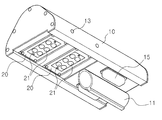
Fig. 1 is a view showing a street lamp according to the present invention. Fig.
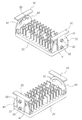
Fig. 2 is an exemplary cross-sectional view showing a configuration of the present invention. Fig.
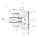
Fig. 3 is a diagram showing an example of the configuration of the operation part of the LED module, which is a main part of the present invention; Fig.
4 is a diagram showing an example of the configuration of a stop wave which is a main part of the present invention;
The construction of the present invention will be described in detail with reference to the accompanying drawings.
A streetlight comprising an LED module (20) constituting a plurality of LED light emitting lamps (21), the angle of which is adjusted by the lighting fixture body (10)
A lighting fixture body (10) constituting a columnar joint part (11) for coupling the pillars and constituting a module mounting part (12) for mounting at least two LED modules (21);
An
A
A
The
The
The
In this case, the
The operation state of the present invention constructed as described above will be described as follows.
First, the bottom surface is formed as a flat surface, and the upper surface thereof is elevated so as to have a center as a roof, so that snow or other rainwater can be stacked or floated easily without being floated, and then a post- An
The
Next, circular
The
The
At this time, the
When the streetlight is installed in the streetlight, the
In the above-mentioned design, the value of the industrial use will be great, for example, by reducing the power consumption by effectively using the LED lamp in installing a street light or a security light.
10: luminaire body 11: holding joint part 12: module coupling part
13:
21: LED lamp 30: Hinge bracket 31: Hinge bracket
32; Hinge shaft 33: Fixing bolt 35: Stop wave
36: stop ball 37: spring 38: adjusting bolt
40: Position fixing bracket 41: Guide slot 50: Stop bracket
51: Stop hole
Claims (3)
A lighting fixture body (10) constituting a columnar joint part (11) for coupling the pillars and constituting a module mounting part (12) for mounting at least two LED modules (21);
An LED module 20 configured to be rotatable on both ends of the module mounting part 12 of the lamp body 10 so as to be adjustable in angle;
A hinge bracket 30 mounted on the module mounting part 12 of the lamp body 10 and constituting a hinge piece 31 for mounting each LED module 20;
And a stop bracket (40) and a stop bracket (50) integrally joined to both ends of the LED module (20).
The lamp body 10 is formed so that its bottom surface is flat and its upper surface rises like a roof to a high center so that snow or other rainwater can be easily stacked or laminated, (12) constituting an identification display (15) on both sides thereof and at least two or more LED modules (20) mounted on the tip side thereof;
The LED module 20 is configured such that both ends thereof are coupled to the hinge pieces 31 of the hinge bracket 30 coupled to the module mounting portion 12 of the lamp body 10 so as to be individually rotatable, Wherein the light source is a light source.
The hinge piece 31 on one side of the hinge bracket 30 configured such that both sides of the LED module 20 are coupled to the module mounting portion 12 of the lamp body 10 is fixed separately from the hinge shaft 32, And an arc-shaped guiding slot 41 guiding the fixing bolt 33 through the position fixing bracket 40 formed integrally with the corresponding LED module 20 is constructed So as to fix the position of the LED module (20) by tightening the fixing bolt (33) coupled to the guide slot (41);
The hinge piece 31 on the other side of the hinge bracket 30 configured such that both sides of the LED module 20 are coupled to the module mounting portion 12 of the lamp body 10 is separated from the hinge shaft 32, A stop wave 35 is formed so that the ball 36 is mounted on the spring 37 to adjust the elastic force with the adjustment bolt 38 and the stop bracket 50 integrally formed with the corresponding LED module 20 A stop hole 51 is formed at a predetermined interval on an arc so that the LED module 20 is rotated in a stepwise manner;
The adjustment bolt 13 is formed at a position corresponding to the fixing bolt 33 and the stop wave 35 formed on the hinge bracket 30 integrally joined to the module mounting portion 12 of the lamp body 10, And the adjusting bolt (38) of the stopper (33) and the stopper (35) are easily manipulated.
Priority Applications (1)
| Application Number | Priority Date | Filing Date | Title |
|---|---|---|---|
| KR2020150006005U KR200485097Y1 (en) | 2015-09-09 | 2015-09-09 | The lamps light angle easy to adjust |
Applications Claiming Priority (1)
| Application Number | Priority Date | Filing Date | Title |
|---|---|---|---|
| KR2020150006005U KR200485097Y1 (en) | 2015-09-09 | 2015-09-09 | The lamps light angle easy to adjust |
Publications (2)
| Publication Number | Publication Date |
|---|---|
| KR20170001005U true KR20170001005U (en) | 2017-03-17 |
| KR200485097Y1 KR200485097Y1 (en) | 2017-11-28 |
Family
ID=58496420
Family Applications (1)
| Application Number | Title | Priority Date | Filing Date |
|---|---|---|---|
| KR2020150006005U KR200485097Y1 (en) | 2015-09-09 | 2015-09-09 | The lamps light angle easy to adjust |
Country Status (1)
| Country | Link |
|---|---|
| KR (1) | KR200485097Y1 (en) |
Cited By (3)
| Publication number | Priority date | Publication date | Assignee | Title |
|---|---|---|---|---|
| KR101890189B1 (en) * | 2018-06-28 | 2018-08-21 | (주)세광산업조명 | Lighting apparatus |
| KR102078256B1 (en) * | 2019-07-01 | 2020-02-17 | 주식회사 대운엘앤씨 | Light pollution prevention Outdoor Lighting Modules |
| KR20200082484A (en) * | 2018-12-28 | 2020-07-08 | 주식회사 세미웰전자 | Led lights |
Families Citing this family (1)
| Publication number | Priority date | Publication date | Assignee | Title |
|---|---|---|---|---|
| KR102041735B1 (en) * | 2018-12-17 | 2019-11-20 | 신효상 | Lighting module with zoom function |
Citations (12)
| Publication number | Priority date | Publication date | Assignee | Title |
|---|---|---|---|---|
| KR20070041519A (en) | 2004-06-17 | 2007-04-18 | 월리텍스 마이크로일렉트로닉스 리미티드 | Improved connector and device for flexibly connectable computer systems |
| JP2007122936A (en) * | 2005-10-26 | 2007-05-17 | Matsushita Electric Works Ltd | Illumination fixture |
| KR20080011080A (en) | 2006-07-27 | 2008-01-31 | 키몬다 노스 아메리카 코포레이션 | Read disturb sensor for phase change memories |
| KR20100002566A (en) | 2008-06-30 | 2010-01-07 | 주식회사 코오롱 | Aramid nonwoven fabric and preparation method thereof |
| KR20100059941A (en) | 2007-09-04 | 2010-06-04 | 콘티넨탈 테베스 아게 운트 코. 오하게 | Navigation system for a complex, menu-controlled, multifunctional vehicle system |
| KR20110133116A (en) * | 2010-06-04 | 2011-12-12 | (주)엔엠엘이디 | Lighting apparatus using led |
| KR20120010881A (en) | 2010-07-27 | 2012-02-06 | 현대자동차주식회사 | a variable compression ratio apparatus for a vehicle's engine |
| KR101177760B1 (en) * | 2011-05-31 | 2012-08-30 | 한국광기술원 | Illumination device for street light |
| KR20120100528A (en) * | 2011-03-04 | 2012-09-12 | 자화전자 주식회사 | Light distribution angle control possiblity led street light |
| KR20130098555A (en) * | 2012-02-28 | 2013-09-05 | 에스케이네트웍스서비스 주식회사 | Bollard for illuminating border line |
| KR20140093087A (en) | 2013-01-17 | 2014-07-25 | 이승태 | Bike seat structures for infant |
| KR20140116113A (en) | 2011-12-20 | 2014-10-01 | 도소 가부시키가이샤 | Strontium-exchanged clinoptilolite |
-
2015
- 2015-09-09 KR KR2020150006005U patent/KR200485097Y1/en active IP Right Grant
Patent Citations (12)
| Publication number | Priority date | Publication date | Assignee | Title |
|---|---|---|---|---|
| KR20070041519A (en) | 2004-06-17 | 2007-04-18 | 월리텍스 마이크로일렉트로닉스 리미티드 | Improved connector and device for flexibly connectable computer systems |
| JP2007122936A (en) * | 2005-10-26 | 2007-05-17 | Matsushita Electric Works Ltd | Illumination fixture |
| KR20080011080A (en) | 2006-07-27 | 2008-01-31 | 키몬다 노스 아메리카 코포레이션 | Read disturb sensor for phase change memories |
| KR20100059941A (en) | 2007-09-04 | 2010-06-04 | 콘티넨탈 테베스 아게 운트 코. 오하게 | Navigation system for a complex, menu-controlled, multifunctional vehicle system |
| KR20100002566A (en) | 2008-06-30 | 2010-01-07 | 주식회사 코오롱 | Aramid nonwoven fabric and preparation method thereof |
| KR20110133116A (en) * | 2010-06-04 | 2011-12-12 | (주)엔엠엘이디 | Lighting apparatus using led |
| KR20120010881A (en) | 2010-07-27 | 2012-02-06 | 현대자동차주식회사 | a variable compression ratio apparatus for a vehicle's engine |
| KR20120100528A (en) * | 2011-03-04 | 2012-09-12 | 자화전자 주식회사 | Light distribution angle control possiblity led street light |
| KR101177760B1 (en) * | 2011-05-31 | 2012-08-30 | 한국광기술원 | Illumination device for street light |
| KR20140116113A (en) | 2011-12-20 | 2014-10-01 | 도소 가부시키가이샤 | Strontium-exchanged clinoptilolite |
| KR20130098555A (en) * | 2012-02-28 | 2013-09-05 | 에스케이네트웍스서비스 주식회사 | Bollard for illuminating border line |
| KR20140093087A (en) | 2013-01-17 | 2014-07-25 | 이승태 | Bike seat structures for infant |
Cited By (3)
| Publication number | Priority date | Publication date | Assignee | Title |
|---|---|---|---|---|
| KR101890189B1 (en) * | 2018-06-28 | 2018-08-21 | (주)세광산업조명 | Lighting apparatus |
| KR20200082484A (en) * | 2018-12-28 | 2020-07-08 | 주식회사 세미웰전자 | Led lights |
| KR102078256B1 (en) * | 2019-07-01 | 2020-02-17 | 주식회사 대운엘앤씨 | Light pollution prevention Outdoor Lighting Modules |
Also Published As
| Publication number | Publication date |
|---|---|
| KR200485097Y1 (en) | 2017-11-28 |
Similar Documents
| Publication | Publication Date | Title |
|---|---|---|
| US10634324B2 (en) | LED-based illumination assembly with adjustable irradiation angle | |
| KR101049177B1 (en) | LED lighting device | |
| KR100944521B1 (en) | Lighting apparatus for street lamp | |
| KR101221196B1 (en) | Led flat luminaires | |
| KR100942000B1 (en) | Led illumination apparatus | |
| CN101608764B (en) | LED illumination device | |
| US9732919B2 (en) | Multifunctional module-type light | |
| KR200485097Y1 (en) | The lamps light angle easy to adjust | |
| KR100936942B1 (en) | Prefabricated led lighting equipment | |
| CN101846291B (en) | Light emitting diode lamp | |
| CN201795396U (en) | LED down lamp | |
| KR100900953B1 (en) | Street light | |
| KR20110047770A (en) | Road Lamp with LED | |
| KR200470352Y1 (en) | LED Lighting | |
| CN205037252U (en) | Lens and light source module | |
| KR20090011424U (en) | LED lamp street light | |
| JP6555475B2 (en) | Illumination method and illumination system | |
| KR101339039B1 (en) | Lighting apparatus regulating irradiation of light | |
| KR101646533B1 (en) | Irradiation position adjustable outdoor LED lamp excellent with compatibility | |
| KR101228469B1 (en) | Adjusting apparatus for irradiated angle of lighting device for led circuit board | |
| CN102734675B (en) | Novel module lamp with integrated combination of wiring channel and mounting member | |
| CN203036411U (en) | Light-emitting diode (LED) grille lamp for subway stations | |
| JP2013131299A (en) | Lamp fitting | |
| CN209371013U (en) | A kind of LED ceiling light | |
| CN202109307U (en) | LED energy-saving street lamp capable of adjusting illumination angle |
Legal Events
| Date | Code | Title | Description |
|---|---|---|---|
| A201 | Request for examination | ||
| E902 | Notification of reason for refusal | ||
| E701 | Decision to grant or registration of patent right | ||
| REGI | Registration of establishment |