KR20160138984A - Asymmetric turning film with multiple light sources - Google Patents
Asymmetric turning film with multiple light sources Download PDFInfo
- Publication number
- KR20160138984A KR20160138984A KR1020167027562A KR20167027562A KR20160138984A KR 20160138984 A KR20160138984 A KR 20160138984A KR 1020167027562 A KR1020167027562 A KR 1020167027562A KR 20167027562 A KR20167027562 A KR 20167027562A KR 20160138984 A KR20160138984 A KR 20160138984A
- Authority
- KR
- South Korea
- Prior art keywords
- light
- light source
- optical system
- shape
- turning film
- Prior art date
Links
Images


Classifications
-
- F—MECHANICAL ENGINEERING; LIGHTING; HEATING; WEAPONS; BLASTING
- F21—LIGHTING
- F21V—FUNCTIONAL FEATURES OR DETAILS OF LIGHTING DEVICES OR SYSTEMS THEREOF; STRUCTURAL COMBINATIONS OF LIGHTING DEVICES WITH OTHER ARTICLES, NOT OTHERWISE PROVIDED FOR
- F21V5/00—Refractors for light sources
- F21V5/002—Refractors for light sources using microoptical elements for redirecting or diffusing light
-
- F—MECHANICAL ENGINEERING; LIGHTING; HEATING; WEAPONS; BLASTING
- F21—LIGHTING
- F21V—FUNCTIONAL FEATURES OR DETAILS OF LIGHTING DEVICES OR SYSTEMS THEREOF; STRUCTURAL COMBINATIONS OF LIGHTING DEVICES WITH OTHER ARTICLES, NOT OTHERWISE PROVIDED FOR
- F21V5/00—Refractors for light sources
- F21V5/08—Refractors for light sources producing an asymmetric light distribution
-
- F—MECHANICAL ENGINEERING; LIGHTING; HEATING; WEAPONS; BLASTING
- F21—LIGHTING
- F21V—FUNCTIONAL FEATURES OR DETAILS OF LIGHTING DEVICES OR SYSTEMS THEREOF; STRUCTURAL COMBINATIONS OF LIGHTING DEVICES WITH OTHER ARTICLES, NOT OTHERWISE PROVIDED FOR
- F21V9/00—Elements for modifying spectral properties, polarisation or intensity of the light emitted, e.g. filters
- F21V9/14—Elements for modifying spectral properties, polarisation or intensity of the light emitted, e.g. filters for producing polarised light
-
- G—PHYSICS
- G02—OPTICS
- G02B—OPTICAL ELEMENTS, SYSTEMS OR APPARATUS
- G02B19/00—Condensers, e.g. light collectors or similar non-imaging optics
- G02B19/0004—Condensers, e.g. light collectors or similar non-imaging optics characterised by the optical means employed
- G02B19/0028—Condensers, e.g. light collectors or similar non-imaging optics characterised by the optical means employed refractive and reflective surfaces, e.g. non-imaging catadioptric systems
-
- G—PHYSICS
- G02—OPTICS
- G02B—OPTICAL ELEMENTS, SYSTEMS OR APPARATUS
- G02B19/00—Condensers, e.g. light collectors or similar non-imaging optics
- G02B19/0033—Condensers, e.g. light collectors or similar non-imaging optics characterised by the use
- G02B19/0047—Condensers, e.g. light collectors or similar non-imaging optics characterised by the use for use with a light source
-
- G—PHYSICS
- G02—OPTICS
- G02B—OPTICAL ELEMENTS, SYSTEMS OR APPARATUS
- G02B5/00—Optical elements other than lenses
- G02B5/02—Diffusing elements; Afocal elements
- G02B5/0205—Diffusing elements; Afocal elements characterised by the diffusing properties
- G02B5/021—Diffusing elements; Afocal elements characterised by the diffusing properties the diffusion taking place at the element's surface, e.g. by means of surface roughening or microprismatic structures
- G02B5/0231—Diffusing elements; Afocal elements characterised by the diffusing properties the diffusion taking place at the element's surface, e.g. by means of surface roughening or microprismatic structures the surface having microprismatic or micropyramidal shape
-
- G—PHYSICS
- G02—OPTICS
- G02B—OPTICAL ELEMENTS, SYSTEMS OR APPARATUS
- G02B5/00—Optical elements other than lenses
- G02B5/02—Diffusing elements; Afocal elements
- G02B5/0273—Diffusing elements; Afocal elements characterized by the use
- G02B5/0278—Diffusing elements; Afocal elements characterized by the use used in transmission
-
- G—PHYSICS
- G02—OPTICS
- G02B—OPTICAL ELEMENTS, SYSTEMS OR APPARATUS
- G02B6/00—Light guides; Structural details of arrangements comprising light guides and other optical elements, e.g. couplings
- G02B6/0001—Light guides; Structural details of arrangements comprising light guides and other optical elements, e.g. couplings specially adapted for lighting devices or systems
- G02B6/0011—Light guides; Structural details of arrangements comprising light guides and other optical elements, e.g. couplings specially adapted for lighting devices or systems the light guides being planar or of plate-like form
- G02B6/0033—Means for improving the coupling-out of light from the light guide
- G02B6/005—Means for improving the coupling-out of light from the light guide provided by one optical element, or plurality thereof, placed on the light output side of the light guide
- G02B6/0053—Prismatic sheet or layer; Brightness enhancement element, sheet or layer
-
- G—PHYSICS
- G02—OPTICS
- G02B—OPTICAL ELEMENTS, SYSTEMS OR APPARATUS
- G02B5/00—Optical elements other than lenses
- G02B5/04—Prisms
- G02B5/045—Prism arrays
-
- G—PHYSICS
- G02—OPTICS
- G02B—OPTICAL ELEMENTS, SYSTEMS OR APPARATUS
- G02B6/00—Light guides; Structural details of arrangements comprising light guides and other optical elements, e.g. couplings
- G02B6/0001—Light guides; Structural details of arrangements comprising light guides and other optical elements, e.g. couplings specially adapted for lighting devices or systems
- G02B6/0011—Light guides; Structural details of arrangements comprising light guides and other optical elements, e.g. couplings specially adapted for lighting devices or systems the light guides being planar or of plate-like form
- G02B6/0066—Light guides; Structural details of arrangements comprising light guides and other optical elements, e.g. couplings specially adapted for lighting devices or systems the light guides being planar or of plate-like form characterised by the light source being coupled to the light guide
- G02B6/0068—Arrangements of plural sources, e.g. multi-colour light sources
Landscapes
- Physics & Mathematics (AREA)
- General Physics & Mathematics (AREA)
- Optics & Photonics (AREA)
- Engineering & Computer Science (AREA)
- General Engineering & Computer Science (AREA)
- Spectroscopy & Molecular Physics (AREA)
- Planar Illumination Modules (AREA)
- Non-Portable Lighting Devices Or Systems Thereof (AREA)
- Optical Elements Other Than Lenses (AREA)
Abstract
광학 시스템이 개시된다. 더 자세하게는, 적어도 제1 광원(120) 및 제2 광원(130)을 갖는 비대칭적 터닝 필름(110)을 포함하는 광학 시스템이 개시된다. 비대칭적 터닝 필름을 위한 기하구조의 선택은 제1 광원, 제2 광원, 또는 둘다의 선택적 조명에 따라 상이한 출력 조망각이 가능하게 할 수 있다. 개시된 광학 시스템은 조명 기구 및 디스플레이 둘다에서 적합할 수 있다.An optical system is disclosed. More specifically, an optical system including an asymmetric turning film 110 having at least a first light source 120 and a second light source 130 is disclosed. The choice of the geometry for the asymmetrical turning film may enable different output contrast angles depending on the selective illumination of the first light source, the second light source, or both. The disclosed optical system may be suitable in both the illuminator and the display.
Description
터닝 필름(turning film)은 많은 디스플레이 및 조명 응용에서 빛의 각 분포(angular distribution)를 변화시키기 위해 이용된다. 터닝 필름은 일반적으로 빛을 굴절 및/또는 반사함으로써 작동하는 특징요소를 갖는다. 터닝 필름은 원하는 광 출력을 제공하기 위해 광원과 함께 이용될 수 있다.Turning films are used to change the angular distribution of light in many display and lighting applications. Turning films generally have feature elements that operate by refracting and / or reflecting light. The turning film can be used with a light source to provide the desired light output.
한 양태에서, 본 발명은 광학 시스템(optical system)에 관한 것이다. 광학 시스템은, 상이하게 배향된 광 분포를 갖는 제1 광원 및 제2 광원, 제1 주면 및 제2 주면을 포함하는 비대칭적 터닝 필름(asymmetric turning film)을 포함하고, 제1 주면은 사실상 매끈하고, 제2 주면은 제1 형상을 갖는 제1 면 및 상이한 제2 형상을 갖는 제2 면을 각각 갖는 복수의 미세 구조체를 포함하며, 제1 광원으로부터의 빛은 제2 면이 아니라 제1 면에 의해 우선적으로 반사되고, 제2 광원으로부터의 빛은 제1 면이 아니라 제2 면에 의해 우선적으로 반사된다. 어떤 실시 형태에서는, 광학 시스템은 제1 광원 및 제2 광원 중 적어도 하나로부터의 빛을 이송하도록 구성되는 광 가이드(lightguide)를 더 포함한다. 광학 시스템은 제1 비대칭적 터닝 필름으로부터 광 가이드의 마주보는 쪽에 배치되는 제2 터닝 필름을 포함할 수 있다. 어떤 실시 형태에서는, 제2 터닝 필름은 비대칭적 터닝 필름일 수 있다. 어떤 실시 형태에서는, 비대칭적 터닝 필름은 제3 형상을 갖는 제3 면 및 상이한 제4 형상을 갖는 제4 면을 각각 갖는 복수의 미세 구조체를 갖고, 제1 광원으로부터의 빛은 제4 면이 아니라 제3 면에 의해 우선적으로 반사되고, 제2 광원으로부터의 빛은 제3 면이 아니라 제4 면에 의해 우선적으로 반사된다.In one aspect, the present invention relates to an optical system. The optical system includes a first light source and a second light source having differently directed light distributions, an asymmetric turning film comprising a first major surface and a second major surface, wherein the first major surface is substantially smooth , The second major surface includes a plurality of microstructures each having a first surface having a first shape and a second surface having a different second shape, wherein light from the first light source is incident on the first surface And the light from the second light source is preferentially reflected by the second surface instead of the first surface. In certain embodiments, the optical system further comprises a lightguide configured to transmit light from at least one of the first light source and the second light source. The optical system may include a second turning film disposed on the opposite side of the light guide from the first asymmetrical turning film. In certain embodiments, the second turning film may be an asymmetric turning film. In some embodiments, the asymmetric turning film has a plurality of microstructures each having a third side having a third shape and a fourth side having a different fourth shape, wherein light from the first light source is not a fourth side Is preferentially reflected by the third surface, and light from the second light source is preferentially reflected by the fourth surface, not the third surface.
어떤 실시 형태에서는, 광 가이드는 쐐기형이다. 어떤 실시 형태에서는, 광학 시스템은 제1 광원 및 제2 광원 중 적어도 하나로부터의 빛을 이송하도록 구성되는 제2 광 가이드를 더 포함한다. 어떤 실시 형태에서는, 광 가이드 및 제2 광 가이드는 적층된다. 어떤 실시 형태에서는, 제1 형상은 사실상 평평하고, 제2 형상은 사실상 굴곡진다. 어떤 실시 형태에서는, 복수의 미세 구조체의 각각은 동일한 횡단면 형상이다. 어떤 실시 형태에서는, 제1 형상 및 제2 형상은 둘다 사실상 평평하다. 어떤 실시 형태에서는, 제1 형상 및 제2 형상은 둘다 사실상 굴곡진다.In some embodiments, the light guide is wedge-shaped. In certain embodiments, the optical system further comprises a second light guide configured to transmit light from at least one of the first light source and the second light source. In some embodiments, the light guide and the second light guide are laminated. In some embodiments, the first shape is substantially flat and the second shape is substantially curved. In some embodiments, each of the plurality of microstructures has the same cross-sectional shape. In certain embodiments, both the first shape and the second shape are substantially flat. In some embodiments, both the first shape and the second shape are substantially curved.
어떤 실시 형태에서는, 광학 시스템에서 복수의 미세 구조체 중 각각의 미세 구조체는 제3 형상을 갖는 제3 면을 더 포함하고, 제1 광원으로부터의 빛이 제2 면이 아니라 제1 면 및 제3 면에 의해 우선적으로 반사되거나 또는 제2 광원으로부터의 빛이 제1 면이 아니라 제2 면 및 제3 면에 의해 우선적으로 반사된다. 어떤 실시 형태에서는, 광학 시스템은 제3 형상을 갖는 제3 면 및 상이한 제4 형상을 갖는 제4 면을 각각 포함하는 제2 복수의 미세 구조체를 더 포함하고, 제3 면은 제2 광원이 아니라 제1 광원으로부터의 빛을 우선적으로 반사하며, 제4 면은 제1 광원이 아니라 제2 광원으로부터의 빛을 우선적으로 반사하고, 제1 형상, 제2 형상, 제3 형상, 및 제4 형상 중 적어도 두개는 상이하다. 어떤 실시 형태에서는, 비대칭적 터닝 필름의 제2 주면은 반사 방지 코팅(antireflective coating) 또는 반사 방지 구조화 표면 중 적어도 하나를 포함한다. 어떤 실시 형태에서는, 제1 면 또는 제2 면 중 적어도 하나는 톱니 또는 사인파 표면(sawtooth or sinusoidal surface)을 포함한다. 어떤 실시 형태에서는, 복수의 미세 구조체는 선형 미세 구조체를 포함한다.In some embodiments, in the optical system, each of the microstructures of the plurality of microstructures further includes a third surface having a third shape, and light from the first light source is incident on the first surface and the third surface Or light from the second light source is preferentially reflected by the second surface and the third surface instead of the first surface. In some embodiments, the optical system further comprises a second plurality of microstructures each comprising a third side having a third shape and a fourth side having a different fourth shape, wherein the third side is not a second light source The first surface reflects light from the first light source preferentially and the fourth surface preferentially reflects light from the second light source rather than the first light source and the first, second, third, and fourth shapes At least two are different. In certain embodiments, the second major surface of the asymmetrical turning film comprises at least one of an antireflective coating or an anti-reflection structured surface. In certain embodiments, at least one of the first or second surface includes a sawtooth or sinusoidal surface. In some embodiments, the plurality of microstructures include linear microstructures.
어떤 실시 형태에서는, 광학 시스템은 두개의 표시 모드(display mode)를 가지며, 제1 모드에서는, 단지 제1 광원만 발광하고, 제2 모드에서는, 단지 제2 광원만 발광한다. 어떤 실시 형태에서는, 광학 시스템은 제3 모드를 갖고, 제3 모드에서는, 제1 광원 및 제2 광원 둘다 발광한다. 어떤 실시 형태에서는, 제1 광원 및 제2 광원 중 적어도 하나는 복수의 LED를 포함한다. 어떤 실시 형태에서는, 제1 광원 및 제2 광원 중 적어도 하나는 사실상 백색광을 방출한다. 어떤 실시 형태에서는, 제1 광원 및 제2 광원 중 적어도 하나는 비백색광(non-white light)을 방출한다.In some embodiments, the optical system has two display modes, in which only the first light source emits light, and in the second mode, only the second light source emits light. In an embodiment, the optical system has a third mode, and in the third mode, both the first light source and the second light source emit light. In some embodiments, at least one of the first light source and the second light source includes a plurality of LEDs. In some embodiments, at least one of the first light source and the second light source substantially emits white light. In some embodiments, at least one of the first light source and the second light source emits non-white light.
다른 한 양태에서, 본 발명은, 표시면 및 두개의 표시 모드를 갖는 광학 시스템으로서, 제1 모드에서는, 표시면이 제1 특성 세트의 조망각(characteristic set of viewing angles)을 갖는 빛을 방출하고, 제2 모드에서는, 표시면이 제2 특성 세트의 조망각을 갖는 빛을 방출하며, 제1 특성 세트의 조망각과 제2 특성 세트의 조망각은 상이한 폭을 갖는 광학 시스템에 관한 것이다.In another aspect, the invention provides an optical system having a display surface and two display modes, wherein in the first mode, the display surface emits light having a characteristic set of viewing angles of the first set of features , In the second mode, the display surface emits light with an angle of refraction of the second set of features, and the angle of view of the first set of features and the angle of convergence of the second set of features have different widths.
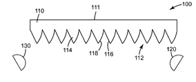
도 1은 다중 광원을 갖는 비대칭적 터닝 필름의 개략적 측면 종단면도이다.
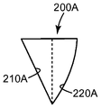
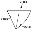
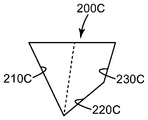
도 2a, 도 2b, 및 도 2c는 도 1의 비대칭적 터닝 필름의 미세 구조체를 위한 예시적인 면 유형을 도시하는 일련의 단면도이다.
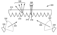
도 3은 도 1의 비대칭적 터닝 필름 및 다중 광원의 작동 및 일반적인 광학 원리를 도시하는 개략적 측면 종단면도이다.
도 4는 제1 세트 및 제2 세트의 특성 조망각을 도시하는 개략적 측면 종단면도이다.
도 5는 제1 세트 및 제2 세트의 특성 조망각을 도시하는 다른 한 개략적 측면 종단면도이다.
도 6은 제1 세트 및 제2 세트의 특성 조망각을 도시하는 다른 한 개략적 측면 종단면도이다.1 is a schematic side elevational cross-sectional view of an asymmetrical turning film having multiple light sources.
2A, 2B, and 2C are a series of cross-sectional views illustrating exemplary surface types for the microstructures of the asymmetric turning film of FIG.
3 is a schematic side elevational cross-sectional view showing the operation and general optical principle of the asymmetrical turning film and multiple light sources of FIG.
4 is a schematic side cross-sectional view showing the first set and the second set of characteristic angles.
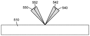
Figure 5 is another schematic side elevational cross-sectional view showing the first set and the second set of characteristic angles.
Figure 6 is another schematic side elevational cross-sectional view showing the first set and the second set of characteristic angles.
비대칭적 터닝 필름은 빛의 유용하거나 또는 바람직한 출력 분포를 제공하기 위해 다중 광원과 함께 이용될 수 있다. 예를 들어, 비대칭적 터닝 필름은 한 광원으로부터의 빛을 반사하지만 다른 한 광원으로부터의 빛은 반사하지 않는 면을 가질 수 있다. 어떤 실시 형태에서는, 비대칭적 터닝 필름은 적어도 제1 면 및 제2 면을 각각 갖는 복수의 미세 구조체 또는 프리즘(prism)을 가질 수 있다. 이러한 면이 대응하는 광원(즉, 면에 의해 우선적으로 반사되는 광원)과 관련해서 상이하게 성형 또는 배향되면, 생성되는 출력 분포가 상이할 수 있다. 어떤 경우에는, 광원은 빛의 가변적 또는 전환 가능한 분포를 생성하도록 선택적으로 구동 또는 조명될 수 있다.Asymmetric turning films can be used with multiple light sources to provide a useful or desirable power distribution of light. For example, an asymmetric turning film may have a surface that reflects light from one light source but does not reflect light from another light source. In certain embodiments, the asymmetric turning film may have a plurality of microstructures or prisms having at least a first side and a second side, respectively. If such a surface is shaped or oriented differently with respect to the corresponding light source (i. E., The light source preferentially reflected by the surface), the resulting output distribution may be different. In some cases, the light source may be selectively driven or illuminated to produce a variable or switchable distribution of light.
도 1은 다중 광원을 갖는 비대칭적 터닝 필름의 개략적 측면 종단면도이다. 광학 시스템(100)은 제1 매끈한 주면(111) 및 제2 구조화 표면(112)을 갖는 비대칭적 터닝 필름(110)을 포함한다. 제2 구조화 표면(112)은 제1 면(116) 및 제2 면(118)을 각각 갖는 복수의 미세 구조체(114)를 포함한다. 제1 광원(120) 및 제2 광원(130)은 그것들이 비대칭적 터닝 필름(110)에 입사하는 빛을 제공하도록 배치된다.1 is a schematic side elevational cross-sectional view of an asymmetrical turning film having multiple light sources. The
비대칭적 터닝 필름(110)은 어떤 적합한 두께든 가질 수 있고 어떤 적합한 재료로든 제조될 수 있다. 어떤 실시 형태에서는, 비대칭적 터닝 필름(110)은 폴리카보네이트, 폴리에틸렌 테레프탈레이트, 폴리에틸렌 나프탈레이트, 폴리(메틸 메타크릴레이트), 및 그것들의 공중합체 및 블렌드와 같은 중합체 재료로부터 형성될 것이다. 어떤 실시 형태에서는, 비대칭적 터닝 필름(110)은 입사광을 바람직하지 않게 산란시키는 것을 회피하기 위해 광학상 투명하거나 또는 낮은 탁도 및 높은 투명도를 가질 수 있다. 어떤 실시 형태에서는, 비대칭적 터닝 필름은 충분히 광범위한 각도에서 완전 내부 반사가 발생하는 것을 보장하기 위해 1.5 이상과 같은 충분히 높은 굴절률을 가질 수 있다. 다른 적합한 재료에는 아크릴계, 폴리스티렌, 메틸 스티렌, 아크릴레이트, 폴리프로필렌, 폴리비닐 클로라이드 등이 포함된다. 어떤 실시 형태에서는, 가요성 필름을 생산하기 위해 비대칭적 터닝 필름(110)의 재료, 치수, 또는 둘다가 선택될 수 있다.The
제1 평탄면(111)은 사실상 매끈하다. 그러나, 제1 평탄면(111)은 모든 실시 형태에서 완전히 매끈할 필요는 없으며, 표면이 미세 구조체를 갖지 않는다면, 사실상 평탄면이라고 할 수 있다. 예를 들어, 안티-아웃 또는 눈부심 방지 비디드 코팅(anti-wetout or anti-glare beaded coating)이 제1 평탄면(111)의 표면 상에 포함 또는 결합될 수 있고, 그러한 표면은 이 출원의 목적상 여전히 사실상 매끈하다고 간주될 수 있다. 다시 말해서, 매끈하다는 것은 거칠지 않다는 의미로 이용되는 것이 아니고, 그것은 구조화되지 않았다는 의미로 이용된다.The first
제2 구조화 표면(112)은 미세 구조체(114)를 포함한다. 미세 구조체(114)의 각각은 선형 미세 구조체일 수 있고, 즉, 미세 구조체(114)는 사실상 동일하거나 또는 전적으로 동일한 단면 형상을 갖는 방향을 따라(도 1의 예시적 구성에서는, 지면으로 들어가는/지면으로부터 나오는 축을 따라) 연장될 수 있다. 비대칭적 터닝 필름(110)의 미세 구조체(114), 및 더 일반적으로는 제2 구조화 표면(112)은 미세 복제 공정과 같은 어떤 적합한 공정을 통해서든 형성될 수 있다. 예를 들어, 제2 구조화 표면(112)은 원하는 구조체의 네거티브(negative)을 갖는 적합한 공구를 절삭(플라이 커팅(fly cutting), 스레드 커팅(thread cutting), 또는 다이아몬드 터닝(diamond turning) 등)하고 유연하지만 경화 가능한 재료를 공구 표면에 대해 누름으로써 성형될 수 있다. 재료는 후속적으로 경화되고(예를 들어, 자외선 광과 같은 빛에 대한 노출에 의해), 원하는 특징요소를 갖는 제2 구조화 표면(112)을 남길 수 있다. 주조 및 경화 공정과 함께 공구의 2광자 마스터링(two-photon mastering)과 같은 포토리소그래피(photolithography), 또는 훨씬 직접적인 가공 또는 첨가적 3차원 인쇄 공정를 이용하여, 전기도금, 레이저 절삭(laser cut), 또는 에칭(etched)된 공구에 의해 주조 및 경화시키는 것을 비롯한, 다른 공정들이 가능할 수 있다.The second structured
미세 구조체(114)는 모두 동일할 수 있거나 또는 그것들은 상이할 수 있다. 미세 구조체(114)의 패턴(pattern) 및 배열이 이 출원의 어디에서든, 특히 도 2 및 도 3과 함께 더 상세하게 설명된다. 미세 구조체(114)의 각각은 제1 면(116) 및 제2 면(118)을 갖는다. 제1 면(116) 및 제2 면(118)은 광학상 제1 광원(120) 및 제2 광원(130)에 대응한다. 그러한 점에서, 그리고 도 3과 함께 더 상세하게 설명하자면, 제1 면(116)은 제2 광원(130)이 아니라 제1 광원(120)으로부터의 빛을 우선적으로 반사하고, 제2 면(118)은 제2 광원(130)으로부터의 빛을 우선적으로 반사한다. 제2 구조화 표면(112) 상의 미세 구조체의 전반적인 배열은 어떤 적합한 피치(pitch)든 가질 수 있고, 미세 구조체(114)들의 사이에 랜드(land)(평평한 영역)를 갖거나 또는 갖지 않을 수 있다. 미세 구조체(114)는 어떤 적합한 크기든 가질 수 있고, 많은 경우에, 밀리미터 또는 마이크로미터 규모일 수 있으며, 어떤 경우에는 10 마이크로미터와 100 마이크로미터의 사이 또는 10 마이크로미터와 300 마이크로미터의 사이일 수 있다. 미세 특징요소(114)의 피치(pitch) 또는 크기는 증대되거나, 감소되거나, 증대되기도 하고 감소되기도 하거나, 또는 제2 구조화 표면(112)의 전부 또는 부분들에서 일정하게 유지될 수 있다.The
제1 광원(120) 및 제2 광원(130)은 어떤 적합한 광원 또는 광원 조합이든 될 수 있다. 많은 경우에, 제1 광원(120) 및 제2 광원(130)을 위한 광원은 발광 다이오드(light emitting diode)(LED)이다. 제1 광원(120) 및 제2 광원(130)은 단수로 지칭되지만, 각각은 일련의 광원들(a bank or series of light sources)을 나타낼 수 있다. 예를 들어, 제1 광원(120)은 지면으로 들어가는/지면으로부터 나오는 축을 따라 연장되는 일련의 LED일 수 있다. 어떤 실시 형태에서는, 광원은 사실상 백색광을 방출한다. 어떤 실시 형태에서는, 제1 광원(120) 및 제2 광원(130)의 구성요소들 중 어떤 것은 함께 백색광을 생성할 수 있는 상이한 파장의 빛들을 방출한다. "백색" 광은 관찰자가 백색광이라고 인지할 수 있고 응용에 따라 조절되거나 또는 캘리브레이팅(calibrating) 될 수 있는 어떤 적합하고 바람직한 컬러 포인트(color point)든 지칭할 수 있다. 어떤 실시 형태에서는, 제1 광원(120) 및/또는 제2 광원(120)은 전자기 스펙트럼(electromagnetic spectrum)의 자외선 범위, 가시 범위, 또는 근적외선 범위 중 하나 이상에서 빛을 방출할 수 있다. 제1 광원(120) 및 제2 광원(130)은 냉 음극 형광등(cold cathode fluorescent light)(CCFL) 또는, 어떤 실시 형태에서는, 심지어 백열 광원도 될 수 있다. 어떤 적합한 파장 또는 파장 조합, 편광, 점 분산 분포, 및 시준도(degrees of collimation)든 제공하도록, 광원 및 어떤 대응하는 주사, 시준, 또는 다른 광학요소든 선택될 수 있다.The first
제1 면(116)은 제2 광원(130)이 아니라 제1 광원(120)으로부터의 빛을 우선적으로 반사하고, 제2 면(118)은 제1 광원(120)이 아니라 제2 광원(130)으로부터의 빛을 우선적으로 반사하기 때문에, 비대칭적 터닝 필름(110)은, 제1 광원(120)이 조명될 때의 제1 면을 갖는 제1 필름으로서, 제2 광원(130)이 조명될 때의 제2 면을 갖는 제2 필름으로서, 또는 심지어 제1 광원 및 제2 광원이 모두 조명될 때의 제1 필름 및 제2 필름 둘다로서, 사실상 기능을 한다.The
도 2a, 도 2b, 및 도 2c는 도 1의 비대칭적 터닝 필름을 위한 일련의 예시적 미세 구조체 유형이다. 제1 미세 구조체(200A)는 사실상 도 1에 도시된 바와 같다. 제1 면(210A)은 사실상 선형 (또는, 미세 구조체가 지면으로 들어가는/지면으로부터 나오는 축을 따라 연장하기 때문에, 더 자세하게는 평면형)이다. 제2 면(220A)은 사실상 포물선 단면과 일치하게 굴곡진다. 제1 미세 구조체(200A)에서의 파선은 미세 구조체의 기부(비대칭적 터닝 필름의 랜드에 사실상 평행한 평면, 또는 미세 구조체를 포함하지 않는 필름의 최근접 평면 부분)의 중간점으로부터 그것의 정점까지 연장하고, 미세 구조체 축이라고 지칭될 수 있다. 비대칭적 터닝 필름의 미세 구조체 축 및 미세 구조체에 대한 그것의 관계는, 미세 구조체 축과 기부의 사이 및 미세 구조체 축과 미세 구조체의 면의 사이의 각도를 비롯한, 유용한 디스크립티브 메트릭(descriptive metric)일 수 있다. 이 출원의 실시 형태에서, 미세 구조체 축은 대칭축이 아니다.2A, 2B, and 2C are a series of exemplary microstructure types for the asymmetric turning film of FIG. The
제2 미세 구조체(200B)는 비대칭적 터닝 필름을 위한 미세 구조체에서 가능한 설계 변화 중 일부를 예시한다. 제2 미세 구조체(200B)에서, 제1 면(210B)이 미세 구조체 축과 더 넓은 꼭지각(vertex angle)을 이룰지라도, 제1 면(210B)은 여전히 사실상 선형 또는 평면형이다. 제2 면(220B)은 제1 미세 구조체(200A)에서의 그것의 대응하는 면보다 더 완만한 곡선이기도 하다. 물론, 제1 면을 위해서든 또는 제2 면을 위해서든, 포물선, 쌍곡선, 타원형, 또는 원형 단면, 복합 곡률, 또는 몇개의 인접한 굴곡진 단면 또는 평평한 단면에 의해 분리되는 굴곡진 단면을 비롯한, 어떤 곡률이든 가능하다.The
제3 미세 구조체(200C)는, 다면적인 제2 면을 비롯한, 비대칭적 터닝 필름 미세 구조체를 위한 다른 한 예시적 설계를 예시한다. 이 실시 형태에서는, 좌로부터 우로(도 2c의 관점으로부터) 입사하는 빛은 제2 면(220C)에 의해서든 또는 제3 면(230C)에 의해서든 반사될 수 있다. 적어도 광원의 입사 방향 및 시준도에 따라, 좌로부터 우로 입사하는 미세 구조체(200C)에 의해 반사되는 빛은 제2 면(220C)으로부터의 반사에 의해 주로 제어되는 출력 분포, 제3 면(230C)으로부터의 반사에 의해 주로 제어되는 출력 분포, 또는 제2 면 및 제3 면 둘다로부터의 반사에 의한 분포를 가질 수 있다. 어떤 실시 형태에서는, 제2 면 및 제3 면 둘다를 제2 면(220C)이라고, 또는 복합 또는 다면적인 제2 면이라고 기술할 수 있다. 이러한 다면적인 면은 어떤 실시 형태에서는 분할된 출력 분포를 제공할 수 있다. 원하는 궁극적인 광 출력을 달성하기 위해 미세 구조체의 어떤 조합이든 비대칭적 터닝 필름 상에서 활용될 수 있다. 예를 들어, 제3 미세 구조체(200C)는, 제2 면(220C)의 특성 및 제3 면(230C)의 특성을 갖는 제2 면을 각각 갖는 제1 미세 구조체와 제2 미세 구조체를 제각기 교번(또는 다른 방식으로 산재)시키는 것에 의해 대체될 수 있다. 관찰자의 관점으로부터, 교번하는 미세 구조체 설계는 동등한 광 출력 외관을 제공할 수 있다.The
가공된 표면은 미세 구조체의 면 중 어느 것에서든 가능하다. 예를 들어, 톱니, 교번하는 포물선, 사인파, 또는 미세 특징요소(예를 들어, 미세 렌즈를 비롯한)를 갖는 면 기하구조(face geometry)가, 그러한 면에 의해 반사되는 빛의 출력 분포를 더 효과적으로 분산시키거나 또는 형성하기 위해, 가능할 수 있고 요구될 수 있다. 특히, 고도로 시준된 광원을 가지면, 어떤 응용은 비대칭적 터닝 필름의 미세 구조체의 면 중 하나 이상으로부터 반사되는 더 넓은 대역의 빛으로부터 유리할 수 있다.The machined surface can be on any of the faces of the microstructure. For example, a face geometry with teeth, alternating parabolic lines, sine waves, or fine feature elements (including, for example, micro lenses) can be used to more effectively Dispersed, or formed on the substrate. In particular, having a highly collimated light source, some applications may benefit from a broader band of light reflected from one or more of the facets of the asymmetric turning film's microstructures.
도 3은 도 1의 비대칭적 터닝 필름 및 다중 광원의 작동 및 일반적인 광학 원리를 도시하는 개략적 측면 종단면도이다. 광학 시스템(300)은, 제1 면(316) 및 제2 면(318)을 갖는 미세 구조체(314)를 갖는 비대칭적 터닝 필름(310), 제1 광 분포 원추(322) 및 제1 예시적 광선(324)을 갖는 제1 광원(320), 제2 광 분포 원추(332) 및 제2 예시적 광선(334)을 갖는 제2 광원(330), 제1 광원(320) 및 제1 면(316)에 관한 제1 출력 분포(326), 및 제2 광원(330) 및 제2 면(318)에 관한 제2 출력 분포(336)를 포함한다.3 is a schematic side elevational cross-sectional view showing the operation and general optical principle of the asymmetrical turning film and multiple light sources of FIG.
비대칭적 터닝 필름(310)은, 도 1과 함께 기술된 바와 같이, 도 1 및 도 2a 내지 도 2c에서 기술된 바와 같은 미세 구조체(314)를 갖는다. 미세 구조체(314)는 도 3에서는 예시의 편의를 위해 사실상 동일한 것으로 예시되지만, 미세 구조체는 비대칭적 터닝 필름(310)의 하나 이상의 부분을 따라 형상, 크기, 회전, 또는 피치를 변화시킬 수 있다. 어떤 실시 형태에서는, 미세 구조체(314)들이 공간적으로 변화하고, 어떤 실시 형태에서는, 유사한 특성을 갖지만 비대칭적 터닝 필름(310)의 인접한 부분들로부터 상이한 특성을 갖는, 별개의 부분의 미세 구조체(314)들이 있을 수 있다.The
제1 광원(320)으로부터의 빛은 제1 광 분포 원추(322) 내에 방출된다. 시준도는 광원(320) 및 어떤 수반하는 시준 또는 주사 광학요소(예를 들어, 광 가이드)든 모두에 의해 결정될 수 있다. 어떤 실시 형태에서는, 특히, 제1 광원(320)이 일련의 평행한 광원을 포함할 때는, 광 분포 원추들이 효과적으로 합쳐져 연장된 쐐기를 생성한다(예를 들어, 제1 광 분포 원추의 단면이 지면 속으로 또는 밖으로 돌출되듯이). 광원이 CCFL 관과 같은 선형 광원인 실시 형태에서는 광 분포 원추가 연장된 쐐기일 수도 있다. 어떤 경우든, 설명의 목적상, 제1 광원(320)으로부터의 빛은 비대칭적 터닝 필름(310) 상에 입사하는 제1 예시적 광선(324)으로 나타낸다. 비대칭적 터닝 필름(110)이 공기보다 더 높은 굴절률을 가질 것이기 때문에, 공기로부터 터닝 필름 속으로 이동하는(도 3에 묘사된 바와 같이) 빛은, 경계면에서의 프레넬 반사(Fresnel reflection)를 제외하고는, 제2 면(318)에 의해 굴절되지만 사실상 반사되지는 않을 것이다. 이러한 프레넬 반사는 비대칭적 터닝 필름의 표면 상에 반사 방지 코팅 또는 처리를 제공함으로써 저감될 수 있다. 어떤 실시 형태에서는, 나방의 눈 구조체 등과 같은 반사 방지 구조화 표면에 의해 반사 방지가 제공될 수 있다. 완전 내부 반사될 정도로 입사각이 터닝 필름/공기 경계면에 대해 임계치 이하이면, 예시적 광선(324)이 제1 면(316)에 의해 사실상 반사된다. 비대칭적 터닝 필름(310) 상에 입사하는 제1 광원(320)으로부터 방출되는 빛의 전부에 대한 제1 면(316)으로부터의 반사는 제1 세트의 특성 조망각을 갖는 제1 출력 분포(326)를 생성한다. 광학 시스템(300)을 보는 관찰자는 단지 특성 조망각(적어도 제1 광원(320)에 대응하는 빛에 대한)에서만 빛을 인지할 것이다.Light from the first
마찬가지로, 제2 광원(330)으로부터의 빛의 경우에는, 빛이 제2 광 분포 원추(332)의 범위에 들어가고, 제2 예시적 광선(334)에 의해 나타낸다. 제1 광원과 제2 광원은 상이하게 배향되는 광 분포를 갖는다. 예시적 광선(334)은 그것이 제1 면(316)을 통과할 때 굴절되지만, 사실상 반사되지 않는다(프레넬 반사를 제외하고). 제2 예시적 광선(334)은 제2 면(318)에 의해 생성되는 경계면에서 반사되고, 비대칭적 터닝 필름(310) 상에 입사하는 제2 광원(320)으로부터 방출되는 모든 빛의 합은 제2 세트의 특성 조망각을 갖는 제2 출력 분포(336)를 생성한다. 제2 세트의 특성 조망각은, 도 3에 묘사된 바와 같이, 제1 세트의 특성 조망각과 상이할 수 있다. 이것은 면 기하구조, 미세 구조체의 크기와 전반적인 배열 및 광원에 대한 그것의 배치, 또는 파장, 시준, 및 발광 분포(즉, 램버시안(Lambertian))를 비롯한 광원의 광학 특성에 기인할 수 있다. 산란을 최소화하기 위해, 미세 구조체, 터닝 필름의 이면, 또는 심지어, 편광기 등을 비롯한, 도시되지 않은 전반적인 시스템의 다른 구성요소 상에 반사 방지 코팅이 배치될 수 있다.Likewise, in the case of light from the second
어떤 실시 형태에서는, 광학 시스템(300)은 하나 이상의 광 가이드를 포함한다. 광 가이드는, 완전 내부 반사에 의해 빛을 이송하고, 그것의 길이 및/또는 폭을 따라 빛의 추출을 제어할 수 있도록, 주의깊게 설계되고 배열된 특징요소 또는 특수한 기하구조를 갖는, 일반적으로 중실의 투명한 광학 구성요소이다. 이러한 경우에, 광 가이드의 출사면(도 3의 기준계에서는, 아마도 상측일 것인) 상의 각각의 점을 광원에 관한 것과 같은 광 분포 원추의 가상 소스(virtual source)라고 생각하는 것이 유용할 수 있다. 광 가이드의 설계 및 기하구조(예를 들어, 쐐기형 광 가이드와 같은) 및 추출기의 형상 및 분포는 그러한 광 분포 원추의 형상 또는 폭을 변경할 수 있다. 원하는 각도로 고도로 시준된 빛을 방출하기 위해, 특정한 추출기 설계가 이용될 수 있다. 어떤 실시 형태에서는, 광학 시스템(300)은 광원의 각각이 광 가이드의 측면들에 빛을 주사하도록 구성되는 단일의 광 가이드를 포함할 수 있다. 어떤 실시 형태에서는, 제1 광원과 제2 광원 중 하나는 광 가이드 속에 빛을 주사하지만, 제1 광원과 제2 광원 중 다른 하나는 주사하지 않는다. 어떤 실시 형태에서는, 적층 또는 다른 방식으로 수직으로 배치될 수 있는 2개의 광 가이드가 있고, 제1 광원과 제2 광원은 제각기 제1 광 가이드 및 제2 광 가이드 속에 빛을 주사하도록 결부된다. 광학 시스템(300)은 광 가이드 또는 광 가이드들에서 터닝 필름을 마주보는 쪽에 배치되는 경면 또는 반경면 반사기(specular or semi-specular reflector)를 포함할 수도 있다.In some embodiments,
어떤 실시 형태에서는, 광학 시스템(300)은 중공 광 가이드를 포함할 수 있다. 어떤 실시 형태에서는, 그러한 중공 광 가이드는, 소정의 거리만큼 분리된, 강화 경면 반사기(Enhanced Specular Reflector)(ESR) 및 강화 확산 반사기(Enhanced Diffuse Reflector)(EDR)(미국, 미네소타, 세인트폴 소재의 쓰리엠 컴퍼니(3M Company)로부터 구매 가능한)처럼 다층 반사기와 같은 한 쌍의 고도로 반사적인 경면, 반경면, 또는 확산 반사적 필름으로 제조될 수 있다. 빛은 필름들 사이의 중공 광 가이드를 따라 공중으로 반사되고 이송될 수 있다. 어떤 실시 형태에서는, 광 가이드의 원하는 출력 표면 또는 표면들이 천공 또는 저감된 반사율(즉, 증대된 투과율)의 영역을 가져 선택적으로 투광시킬 수 있다. 이러한 천공 또는 투과율 영역은, 점증적, 의사 무작위적(pseudorandom), 또는 균일한 배열을 비롯한, 어떤 유용한 패턴으로든 배열될 수 있다. 어떤 경우에는, 트랜스플렉터(transflector)가 중공 광 가이드에서의 필름 중 하나 또는 둘다로서 제공될 수 있다. 트랜스플렉터는 부분적 반사기, 반사적 편광기, 또는 심지어 휘도 향상 필름일 수 있다. 트랜스플렉터의 부분적 반사는 중공 광 가이드를 따르는 광 이동을 돕고, 트랜스플렉터의 부분적 투과율은 빛이 광학 시스템(300)의 잔부를 향해 광 가이드를 탈출하는 것을 허용한다.In certain embodiments,
어떤 경우에는, 광 가이드 또는 광 가이드들(중실 또는 중공)은 상면 및 저면 둘다로부터 빛을 추출하거나 또는 방출할 수 있다. 상응해서, 광학 시스템(300)은 저면 또는 광 가이드 또는 광 가이드들로부터의 빛을 방향변경(redirect)하도록 배향되는 제2 터닝 필름을 포함할 수 있다. 어떤 실시 형태에서는, 이러한 제2 터닝 필름은 비대칭적 터닝 필름일 수 있고, 어떤 경우에는, 그것은 도 1 및 도 3과 함께 도시되고 기술되는 비대칭적 터닝 필름(110 및 310)의 특성들 중 일부 또는 전부를 공유할 수 있다. 이러한 설계 변경은 특정한 양면 디스플레이 및 조명 기구를 위해 바람직할 수 있다.In some cases, light guides or light guides (solid or hollow) can extract or emit light from both the top and bottom surfaces. Correspondingly, the
도 4는 제1 세트 및 제2 세트의 특성 조망각을 도시하는 개략적 측면 종단면도이다. 비대칭적 터닝 필름(410)은 단순화되어 있고, 디스플레이 또는 조명 기구 내의 광학 구성요소들의 전부를 나타내고자 한다. 예를 들어, 예시되지 않을지라도, 적어도 두개의 광원 및 일련의 미세 구조체는 물론이고, 예를 들어, 전반적인 설계 및 구성에 따라서는, 하나 이상의 광 가이드도 포함될 것으로 추정된다. 도 4의 상황에서(그리고 도 5 및 도 6의 경우에), 비대칭적 터닝 필름(410)의 상면이 표시면이라고 간주될 수 있다. 도 4는 두 세트의 특성 조망각을 예시한다. 이러한 특성 각도(광학 시스템의 구성에 따라 원추형 또는 쐐기형일 수도 있는)는 관찰자가 이미지 데이터(image data)(디스플레이인 경우)든 또는 빛(조명 기구 또는 램프인 경우)이든 인지할 수 있는 조망각을 나타낸다. 제1 세트의 특성 각도(440) 및 제2 세트의 특성 각도(450)는 원하는 응용에 따라 광범위하게 변할 수 있다. 이 예시에서, 제1 세트의 특성 각도(440)는 비대칭적 터닝 필름의 미세 구조체의 제1 면과 상호작용하는 제1 광원으로부터의 빛과 부합한다. 마찬가지로, 제2 세트의 특성 각도(450)는 비대칭적 터닝 필름의 미세 구조체의 제2 면과 상호작용하는 제2 광원으로부터의 빛과 부합한다. 이러한 세트들의 특성 각도의 정의는 응용에 따라 변할 수도 있다. 예를 들어, 한 세트의 특성 각도의 에지(edge)는 광 강도가 최대치의 절반까지 낮아지는 점(FWHM)이라고 정의될 수 있거나, 또는 그것은 그것이 인지 가능성, 판독 가능성, 또는 심지어 광 강도에 관한 상이한 임의의 값의 임계치를 초과하는 곳일 수 있다. 어떤 실시 형태에서는, 제1 세트의 특성 각도(440)와 제2 세트의 특성 각도(450)는 중첩한다. 제1 세트의 특성 각도(440)는 그것이 제2 세트의 특성 각도(450)와 공유하는 중간선(442)을 갖는다. 광학 시스템의 설계에 따라, 중간선은 광학 시스템의 출사 또는 표시면에 수직할 수 있거나 또는 그것은 각도를 이룰 수 있다(즉, 한 세트의 특성 각도가 축 상에 중심을 두지 않을 수 있다). 어떤 실시 형태에서는, 제1 세트의 특성 각도 및 제2 세트의 특성 각도의 각각은 상이한 중간선을 가질 수 있다. 도 4에 예시되는 분포는 조명 기구 및 디스플레이를 위해 적합할 수 있다. 예를 들어, 제1 세트의 특성 각도(440)는 램프 또는 조명 기구에서의 협대역 작업광 모드(narrow band task light mode)를 위한 것이거나 또는 이 광학 시스템을 포함하는 디스플레이를 위한 프라이버시 모드(privacy mode), 고휘도, 저전력, 또는 일광 판독성 모드(sunlight readability mode)일 수 있다. 제2 세트의 특성 각도는 조명 기구인 경우의 광범위한 환경 또는 영역 조명을 위해 또는 디스플레이인 경우의 공유 모드를 위해 유용할 수 있다. 두 세트의 특성 각도 모두, 원하면, 협력해서 하이브리드 기능성(hybrid functionality)을 제공할 수 있다. 어떤 적합한 범위의 각도든 이용될 수 있다.4 is a schematic side cross-sectional view showing the first set and the second set of characteristic angles. The
도 5는 제1 세트 및 제2 세트의 특성 조망각을 도시하는 다른 한 개략적 측면 종단면도이다. 이 경우에, 제1 세트의 특성 각도(540)와 제2 세트의 특성 각도(550)는 유사한 각 폭(angular width)을 갖지만, 상이한 중간선을 갖는다. 제1 중간선(552) 및 제2 중간선(542)은 둘다, 도 4에서처럼 전체 광학 시스템을 나타내는, 비대칭적 필름(510)의 출사면의 수직선으로부터 각도를 이루게 제공된다. 이와 같은 분포 구성은 방향성 조명을 위해 또는 흥미롭거나 또는 심미적인 효과를 위해 두개의 상이한 색상을 제공하기에 적합할 수 있다.Figure 5 is another schematic side elevational cross-sectional view showing the first set and the second set of characteristic angles. In this case, the first set of
도 6은 제1 세트 및 제2 세트의 특성 조망각을 도시하는 다른 한 개략적 측면 종단면도이다. 여기서, 중간선(642)을 갖는 제1 세트의 특성 각도(640)는, 제1 세트와 공통의 중간선을 갖는 분할된 제2 세트의 특성 각도(650)에 의해 부분적으로 중첩되는, 사실상 중앙에 있는 광대역이다. 도 4 및 도 5에서처럼, 비대칭적 터닝 필름(610)은 광학 시스템의 잔부를 나타낸다. 도 6에 예시되는 분포를 위한 응용은, 동시에 조명되면, 항법(navigation) 및 정렬(alignment)을 포함한다. 예를 들어, 녹색광은 제1 광원에 의해 제공될 수 있고 제1 세트의 특성 각도 내에서 조망 가능하며, 제2 광원은 제2 세트의 특성 각도 내의 적색광을 제공할 수 있다. 그러면, 관찰자는, 예를 들어, 자신 또는 자신이 제어하고 있는 자동차, 보트, 또는 비행기와 같은 교통수단이 목표 축(중간선(642))과 사실상 정렬되었는지(녹색으로 보일 것임), 축을 약간 벗어났는지(황색으로, 또는 녹색과 적색이 함께 보일 것임), 또는 축을 사실상 벗어났는지(적색으로 보일 것임)에 관한 시각적 단서를 가질 것이다. 다른 응용 및 묘사된 분포들의 조합 및 변경이 바람직할 수 있고, 도 4, 도 5, 및 도 6에서 제공되는 실시예 및 예시는 단지 이용 가능한 다양성의 샘플을 제공하려는 것이다.Figure 6 is another schematic side elevational cross-sectional view showing the first set and the second set of characteristic angles. Here, the first set of
이 명세서에 기술되는 광학 시스템을 포함하는 디스플레이는, 편광기(흡수하고 반사하는)와 같은 추가적 종래의 디스플레이 구성요소를 포함할 수 있고, 액정(liquid crystal)(LC) 패널은 픽셀을 포함하고, 적색, 녹색, 및 청색과 같은 상이한 색상들에 대응할 수 있는 서브픽셀(subpixel)을 갖는다. 예를 들어, 비대칭적 터닝 필름은 편광기들 중 하나에 겹쳐지거나 또는 인접하게 배치될 수 있다. 디스플레이를 비롯한 조명 기구 및 램프는, 추가적 터닝 필름(비대칭적 또는 대칭적), 휘도 향상 필름, 확산기, 색 필터(color filter), 반사기, 편광기 등을 비롯한, 어떤 적합한 광학 구성요소 또는 필름이든 포함할 수도 있다. 근본적으로, 이 명세서에서 기술되는 광학 시스템은 이러한 응용들의 사이에서 유사하게 유지된다.A display comprising an optical system as described herein may include additional conventional display components such as polarizers (absorbing and reflecting), a liquid crystal (LC) panel including pixels, red , Green, and blue colors, as shown in FIG. For example, an asymmetrical turning film may be superimposed on one of the polarizers or disposed adjacent thereto. Illuminators and lamps, including displays, may include any suitable optical component or film, including additional turning films (asymmetric or symmetrical), brightness enhancement films, diffusers, color filters, reflectors, polarizers, It is possible. Fundamentally, the optical system described in this specification remains similar among these applications.
예시적 실시 형태는 다음을 포함한다:Exemplary embodiments include:
항목 1. 광학 시스템으로서,Item 1. As an optical system,
상이하게 배향되는 광 분포를 갖는 제1 광원 및 제2 광원; 및A first light source and a second light source having different light distributions; And
제1 주면 및 제2 주면을 포함하는 비대칭적 터닝 필름 - 제1 주면은 사실상 매끈하며, 제2 주면은 제1 형상을 갖는 제1 면 및 상이한 제2 형상을 갖는 제2 면을 각각 포함하는 복수의 미세 구조체를 포함함 - 을 포함하고;An asymmetrical turning film comprising a first major surface and a second major surface, the first major surface being substantially smooth, the second major surface comprising a first surface having a first shape and a second surface having a second different shape, The microstructure comprising:
제1 광원으로부터의 빛은 제2 면이 아니라 제1 면에 의해 우선적으로 반사되며;The light from the first light source is preferentially reflected by the first side, not the second side;
제2 광원으로부터의 빛은 제1 면이 아니라 제2 면에 의해 우선적으로 반사되는, 광학 시스템.And light from the second light source is preferentially reflected by the second surface, rather than the first surface.
항목 2. 항목 1의 광학 시스템으로서, 제1 광원 및 제2 광원 중 적어도 하나로부터의 빛을 이송하도록 구성되는 광 가이드를 더 포함하는, 광학 시스템.
항목 3. 항목 2의 광학 시스템으로서, 광 가이드는 쐐기형인, 광학 시스템.Item 3. The optical system of
항목 4. 항목 2의 광학 시스템으로서, 제1 광원 및 제2 광원 중 적어도 하나로부터의 빛을 이송하도록 구성되는 제2 광 가이드를 더 포함하는, 광학 시스템.Item 4. The optical system of
항목 5. 항목 4의 광학 시스템으로서, 광 가이드 및 제2 광 가이드는 적층되는, 광학 시스템.Item 5. The optical system of item 4, wherein the light guide and the second light guide are laminated.
항목 6. 항목 1의 광학 시스템으로서, 제1 형상은 사실상 평평하고, 제2 형상은 사실상 굴곡진, 광학 시스템.Item 6. The optical system of item 1, wherein the first shape is substantially flat and the second shape is substantially curved.
항목 7. 항목 1의 광학 시스템으로서, 복수의 미세 구조체의 각각은 동일한 횡단면 형상인, 광학 시스템.Item 7. The optical system of item 1, wherein each of the plurality of microstructures has the same cross-sectional shape.
항목 8. 항목 1의 광학 시스템으로서, 제1 형상 및 제2 형상은 둘다 사실상 평평한, 광학 시스템.Item 8. The optical system of item 1, wherein the first shape and the second shape are both substantially flat.
항목 9. 항목 1의 광학 시스템으로서, 제1 형상 및 제2 형상은 둘다 사실상 굴곡진, 광학 시스템.Item 9. The optical system of item 1, wherein the first shape and the second shape are both substantially curved.
항목 10. 항목 1의 광학 시스템으로서, 복수의 미세 구조체 중 각각의 미세 구조체는 제3 형상을 갖는 제3 면을 더 포함하고, 제1 광원으로부터의 빛이 제2 면이 아니라 제1 면 및 제3 면에 의해 우선적으로 반사되거나, 또는 제2 광원으로부터의 빛이 제1 면이 아니라 제2 면 및 제3 면에 의해 우선적으로 반사되는, 광학 시스템.Item 10. The optical system of Item 1, wherein each of the plurality of microstructures further includes a third surface having a third shape, wherein light from the first light source is incident on the first surface and the second surface, Or the light from the second light source is preferentially reflected by the second surface and the third surface instead of the first surface.
항목 11. 항목 1의 광학 시스템으로서, 제3 형상을 갖는 제3 면 및 상이한 제4 형상을 갖는 제4 면을 각각 포함하는 제2 복수의 미세 구조체를 더 포함하고, 제3 면은 제2 광원이 아니라 제1 광원으로부터의 빛을 우선적으로 반사하고, 제4 면은 제1 광원이 아니라 제2 광원으로부터의 빛을 우선적으로 반사하며, 제1 형상, 제2 형상, 제3 형상, 및 제4 형상 중 적어도 두개는 상이한, 광학 시스템.Item 11. The optical system of Item 1 further comprising a second plurality of microstructures each including a third surface having a third shape and a fourth surface having a different fourth shape, And the fourth surface preferentially reflects light from the second light source rather than the first light source, preferentially reflecting light from the first light source, but not the first, second, third, Wherein at least two of the features are different.
항목 12. 항목 1의 광학 시스템으로서, 비대칭적 터닝 필름의 제2 주면은 반사 방지 코팅 또는 반사 방지 구조화 표면 중 적어도 하나를 포함하는, 광학 시스템.Item 12. The optical system of item 1, wherein the second major surface of the asymmetrical turning film comprises at least one of an anti-reflection coating or an anti-reflection structured surface.
항목 13. 항목 1의 광학 시스템으로서, 비대칭적 터닝 필름의 제1 주면은 반사 방지 코팅 또는 반사 방지 구조화 표면 중 적어도 하나를 포함하는, 광학 시스템.Item 13. The optical system of item 1, wherein the first major surface of the asymmetrical turning film comprises at least one of an anti-reflection coating or an anti-reflection structured surface.
항목 14. 항목 1의 광학 시스템으로서, 제1 면 또는 제2 면 중 적어도 하나는 톱니 또는 사인파 표면을 포함하는, 광학 시스템.Item 14. The optical system of item 1, wherein at least one of the first surface or the second surface includes a toothed or sinusoidal surface.
항목 15. 항목 1의 광학 시스템으로서, 복수의 미세 구조체는 선형 미세 구조체를 포함하는, 광학 시스템.Item 15. The optical system of item 1, wherein the plurality of microstructures comprises a linear microstructure.
항목 16. 항목 1의 광학 시스템으로서, 광학 시스템은 두개의 표시 모드를 갖고, 제1 모드에서는 단지 제1 광원만 발광하며, 제2 모드에서는 단지 제2 광원만 발광하는, 광학 시스템.Item 16. The optical system of item 1, wherein the optical system has two display modes, only the first light source emits light in the first mode, and only the second light source emits light in the second mode.
항목 17. 항목 16의 광학 시스템으로서, 광학 시스템은 제3 모드를 갖고, 제3 모드에서는 제1 광원 및 제2 광원 둘다 발광하는, 광학 시스템.Item 17. The optical system of item 16, wherein the optical system has a third mode, and in the third mode both the first light source and the second light source emit light.
항목 18. 항목 1의 광학 시스템으로서, 제1 광원 및 제2 광원 중 적어도 하나는 복수의 LED를 포함하는, 광학 시스템.Item 18. The optical system of item 1, wherein at least one of the first light source and the second light source includes a plurality of LEDs.
항목 19. 항목 1의 광학 시스템으로서, 제1 광원 및 제2 광원 중 적어도 하나는 사실상 백색광을 방출하는, 광학 시스템.Item 19. The optical system of item 1, wherein at least one of the first light source and the second light source emits substantially white light.
항목 20. 항목 1의 광학 시스템으로서, 제1 광원 및 제2 광원 중 적어도 하나는 비백색광을 방출하는, 광학 시스템.Item 20. The optical system of item 1, wherein at least one of the first light source and the second light source emits non-white light.
항목 21. 항목 2의 광학 시스템으로서, 광 가이드에서 제1 비대칭적 터닝 필름으로부터 마주보는 쪽에 배치되는 제2 터닝 필름을 더 포함하는, 광학 시스템.Item 21. The optical system of
항목 22. 항목 21의 광학 시스템으로서, 제2 터닝 필름은 비대칭적 터닝 필름인, 광학 시스템.Item 22. The optical system of item 21, wherein the second turning film is an asymmetrical turning film.
항목 23. 항목 22의 광학 시스템으로서, 제2 비대칭적 터닝 필름은 제3 형상을 갖는 제3 면 및 상이한 제4 형상을 갖는 제4 면을 각각 갖는 복수의 미세 구조체를 포함하고, 제1 광원으로부터의 빛은 제4 면이 아니라 제3 면에 의해 우선적으로 반사되며, 제2 광원으로부터의 빛은 제3 면이 아니라 제4 면에 의해 우선적으로 반사되는, 광학 시스템.Item 23. The optical system of Item 22, wherein the second asymmetric turning film comprises a plurality of microstructures each having a third side having a third shape and a fourth side having a different fourth shape, Wherein the light from the first light source is preferentially reflected by the third surface, not the fourth surface, and the light from the second light source is preferentially reflected by the fourth surface instead of the third surface.
항목 24. 표시면 및 두개의 표시 모드를 갖는 광학 시스템으로서, 제1 모드에서는 표시면이 제1 특성 세트의 조망각을 갖는 빛을 방출하고, 제2 모드에서는 표시면이 제2 특성 세트의 조망각을 갖는 빛을 방출하며, 제1 특성 세트의 조망각과 제2 특성 세트의 조망각은 상이한 폭을 갖는, 광학 시스템.Item 24. An optical system having a display surface and two display modes, wherein the display surface emits light having an angle of refraction of the first set of features and the display surface emits light of a second set of features Wherein the viewing angle of the first set of features and the angle of convergence of the second set of features have different widths.
항목 25. 항목 1의 광학 시스템을 포함하는 조명 기구.Item 25. A lighting fixture comprising the optical system of item 1.
항목 26. 항목 1의 광학 시스템을 포함하는 디스플레이.Item 26. A display comprising an optical system of item 1.
도면에서의 요소에 대한 기술은, 달리 나타내지 않는 한, 다른 도면에서의 대응하는 요소에 동등하게 적용되는 것을 알아야 한다. 본 발명은 전술된 특정 실시예 및 실시 형태에 제한되는 것으로 간주되어서는 안 되는데, 그 이유는, 본 발명의 다양한 태양들의 설명을 용이하게 하기 위하여 그러한 실시 형태가 상세히 기술되어 있기 때문이다. 오히려, 본 발명은, 첨부된 청구범위 및 그것들의 동등물에 의해 정해지는 바와 같은 본 발명의 범위 내에 드는 다양한 변경, 동등한 공정, 및 대안적 장치를 비롯한, 본 발명의 모든 양태를 망라하는 것으로 이해하여야 한다.It should be noted that the description of the elements in the figures applies equally to the corresponding elements in the other figures, unless otherwise indicated. The present invention should not be construed as limited to the specific embodiments and embodiments described above because such embodiments are described in detail so as to facilitate describing the various aspects of the present invention. Rather, the present invention is to be understood as embracing all aspects of the invention, including various modifications, equivalent processes, and alternative devices that fall within the scope of the invention as defined by the appended claims and their equivalents. shall.
Claims (15)
상이하게 배향되는 광 분포를 갖는 제1 광원 및 제2 광원; 및
제1 주면 및 제2 주면을 포함하는 비대칭적 터닝 필름(asymmetric turning film) - 제1 주면은 사실상 매끈하며, 제2 주면은 제1 형상을 갖는 제1 면 및 상이한 제2 형상을 갖는 제2 면을 각각 포함하는 복수의 미세 구조체를 포함함 - 을 포함하고;
제1 광원으로부터의 빛은 제2 면이 아니라 제1 면에 의해 우선적으로 반사되며;
제2 광원으로부터의 빛은 제1 면이 아니라 제2 면에 의해 우선적으로 반사되는, 광학 시스템.As an optical system,
A first light source and a second light source having different light distributions; And
An asymmetric turning film comprising a first major surface and a second major surface, the first major surface being substantially smooth, the second major surface having a first surface having a first shape and a second surface having a different second shape A plurality of microstructures each including a plurality of microstructures;
The light from the first light source is preferentially reflected by the first side, not the second side;
And light from the second light source is preferentially reflected by the second surface, rather than the first surface.
Applications Claiming Priority (3)
| Application Number | Priority Date | Filing Date | Title |
|---|---|---|---|
| US201461973720P | 2014-04-01 | 2014-04-01 | |
| US61/973,720 | 2014-04-01 | ||
| PCT/US2015/022925 WO2015153329A2 (en) | 2014-04-01 | 2015-03-27 | Asymmetric turning film with multiple light sources |
Publications (1)
| Publication Number | Publication Date |
|---|---|
| KR20160138984A true KR20160138984A (en) | 2016-12-06 |
Family
ID=53264730
Family Applications (1)
| Application Number | Title | Priority Date | Filing Date |
|---|---|---|---|
| KR1020167027562A KR20160138984A (en) | 2014-04-01 | 2015-03-27 | Asymmetric turning film with multiple light sources |
Country Status (8)
| Country | Link |
|---|---|
| US (1) | US10371350B2 (en) |
| EP (2) | EP3748408A1 (en) |
| JP (2) | JP2017511573A (en) |
| KR (1) | KR20160138984A (en) |
| CN (1) | CN106170720B (en) |
| SG (1) | SG11201608201PA (en) |
| TW (1) | TW201541148A (en) |
| WO (1) | WO2015153329A2 (en) |
Cited By (1)
| Publication number | Priority date | Publication date | Assignee | Title |
|---|---|---|---|---|
| KR20180117149A (en) * | 2016-02-22 | 2018-10-26 | 루미레즈 엘엘씨 | Asymmetric light intensity distribution from luminaire |
Families Citing this family (12)
| Publication number | Priority date | Publication date | Assignee | Title |
|---|---|---|---|---|
| US10388230B2 (en) | 2014-05-30 | 2019-08-20 | 3M Innovative Properties Company | Temporally multiplexing backlight with asymmetric turning film |
| CN107750348A (en) | 2015-06-16 | 2018-03-02 | 3M创新有限公司 | Display including switchable back source and preceding skin covering of the surface |
| US10761320B2 (en) | 2015-12-09 | 2020-09-01 | 3M Innovative Properties Company | Optical stack including a grating |
| JP2019537056A (en) * | 2016-11-03 | 2019-12-19 | スリーエム イノベイティブ プロパティズ カンパニー | Multiplexed backlight with asymmetric turning film |
| TW201918700A (en) * | 2017-05-05 | 2019-05-16 | 美商3M新設資產公司 | Scatterometry system and method of using the same |
| US10489613B2 (en) | 2017-11-15 | 2019-11-26 | Dell Products L.P. | System and method of controlling light emissions of displays |
| US10684507B2 (en) | 2018-03-19 | 2020-06-16 | Dell Products L.P. | System and method of controlling light emissions of displays |
| CN111221062B (en) * | 2020-03-19 | 2022-02-08 | 宁波舜宇车载光学技术有限公司 | Display device |
| CN211741786U (en) | 2020-03-19 | 2020-10-23 | 中强光电股份有限公司 | Double-screen display device |
| CN212675319U (en) | 2020-08-07 | 2021-03-09 | 中强光电股份有限公司 | Light source module and double-screen display device |
| CN112987302B (en) * | 2021-02-05 | 2022-10-18 | 业成科技(成都)有限公司 | Head-mounted display device and display system thereof |
| WO2024076876A1 (en) * | 2022-10-04 | 2024-04-11 | Brightview Technologies, Inc. | Back light unit for backlit displays |
Family Cites Families (48)
| Publication number | Priority date | Publication date | Assignee | Title |
|---|---|---|---|---|
| JP4053626B2 (en) * | 1997-03-11 | 2008-02-27 | 株式会社エンプラス | Surface light source device and asymmetric prism sheet |
| US6752505B2 (en) * | 1999-02-23 | 2004-06-22 | Solid State Opto Limited | Light redirecting films and film systems |
| US6342981B1 (en) | 1999-09-21 | 2002-01-29 | Rose Research, Llc | Zero-displacement phase retarder device and method |
| KR100798711B1 (en) * | 1999-10-08 | 2008-01-28 | 쓰리엠 이노베이티브 프로퍼티즈 캄파니 | Illumination device and display device comprising the same |
| US6356391B1 (en) * | 1999-10-08 | 2002-03-12 | 3M Innovative Properties Company | Optical film with variable angle prisms |
| JP4011287B2 (en) * | 2000-12-25 | 2007-11-21 | 株式会社エンプラス | Light control sheet, surface light source device, and liquid crystal display |
| WO2003065083A1 (en) * | 2002-01-31 | 2003-08-07 | Mitsubishi Rayon Co., Ltd. | Light deflection element and light source apparatus using the same |
| WO2004015330A1 (en) | 2002-08-09 | 2004-02-19 | Mitsubishi Rayon Co., Ltd. | Flat light source device |
| JP2004119143A (en) | 2002-09-25 | 2004-04-15 | Casio Comput Co Ltd | Surface light source |
| JP4019886B2 (en) | 2002-09-30 | 2007-12-12 | オムロン株式会社 | Optical film, surface light source device and liquid crystal display device |
| CN1816719B (en) * | 2003-07-15 | 2011-08-10 | 三菱丽阳株式会社 | Light source device and light deflection element |
| JP4544517B2 (en) * | 2003-07-15 | 2010-09-15 | 三菱レイヨン株式会社 | Light source device |
| JP2005235661A (en) | 2004-02-20 | 2005-09-02 | Citizen Electronics Co Ltd | Backlight |
| KR101114854B1 (en) * | 2004-12-24 | 2012-03-07 | 엘지디스플레이 주식회사 | A backlight unit |
| JP2007041431A (en) | 2005-08-05 | 2007-02-15 | Dainippon Printing Co Ltd | Prism array sheet, edge light type surface illuminant, and transmission type image display device |
| JP2007048688A (en) | 2005-08-12 | 2007-02-22 | Dainippon Printing Co Ltd | Planar light source, and transmission image display device with rear face light source |
| CN1982971A (en) * | 2005-12-12 | 2007-06-20 | 群康科技(深圳)有限公司 | Reflecting polarized wafer, its negative-light mould set and liquid-crystal display device |
| KR20080090961A (en) | 2006-01-27 | 2008-10-09 | 가부시키가이샤 엔프라스 | Surface light source and display |
| JP5243439B2 (en) | 2006-10-06 | 2013-07-24 | スリーエム イノベイティブ プロパティズ カンパニー | Backlight module for autostereoscopic 3D display device and scanning backlight for LCD device |
| JP2008177070A (en) | 2007-01-19 | 2008-07-31 | Sony Corp | Optical control element, planar light source device, and liquid crystal display device |
| KR100838322B1 (en) | 2007-03-28 | 2008-06-13 | 제일모직주식회사 | Light guide panel comprising asymmetric front prism for lcd |
| JP2008305728A (en) | 2007-06-08 | 2008-12-18 | Sharp Corp | Light guide and surface light emitting device |
| TWM331676U (en) | 2007-08-22 | 2008-05-01 | Wellstech Optical Co Ltd | Optical film |
| JP2009093989A (en) | 2007-10-11 | 2009-04-30 | Omron Corp | Plane light source apparatus and liquid crystal display device |
| US8851734B2 (en) | 2008-03-27 | 2014-10-07 | Skc Haas Display Films Co., Ltd. | Light guiding film having light extraction features |
| JP4513918B2 (en) * | 2008-06-03 | 2010-07-28 | エプソンイメージングデバイス株式会社 | Illumination device and electro-optical device |
| CN102257314B (en) | 2008-12-25 | 2014-11-05 | 三菱丽阳株式会社 | Light guide for light source device and method for manufacturing the same |
| WO2011084303A2 (en) | 2009-12-17 | 2011-07-14 | 3M Innovative Properties Company | Light redirecting constructions |
| SG181652A1 (en) | 2009-12-17 | 2012-07-30 | 3M Innovative Properties Co | Light redirecting film laminate |
| TW201131209A (en) | 2010-03-10 | 2011-09-16 | Core Flex Optical Suzhou Co Ltd | Beam splitting film, backlight module, and stereo display apparatus |
| TW201133082A (en) * | 2010-03-18 | 2011-10-01 | Coretronic Corp | Backlight module, stereo display apparatus, and beam splitting film |
| JP2011258532A (en) | 2010-06-11 | 2011-12-22 | Omron Corp | Surface light source device and stereoscopic display device |
| JP5397334B2 (en) | 2010-07-09 | 2014-01-22 | カシオ計算機株式会社 | Driving method of display device |
| JP5589674B2 (en) | 2010-08-23 | 2014-09-17 | 大日本印刷株式会社 | Surface light source device, transmissive display device |
| EP2431786A1 (en) | 2010-09-17 | 2012-03-21 | Bayer MaterialScience AG | Autostereoscopic 3D display |
| CN102011981B (en) | 2010-09-27 | 2012-06-27 | 友达光电股份有限公司 | Display with switchable visual angle and backlight module thereof |
| JP5278412B2 (en) | 2010-11-17 | 2013-09-04 | オムロン株式会社 | Surface light source device and stereoscopic display device |
| KR101279979B1 (en) | 2010-11-23 | 2013-07-05 | 제일모직주식회사 | Autostereoscopic 3-dimension image display device |
| US8988336B2 (en) | 2010-12-16 | 2015-03-24 | 3M Innovative Properties Company | Dual-orientation autostereoscopic backlight and display |
| US9244284B2 (en) | 2011-03-15 | 2016-01-26 | 3M Innovative Properties Company | Microreplicated film for autostereoscopic displays |
| WO2012164795A1 (en) * | 2011-05-31 | 2012-12-06 | 三菱電機株式会社 | Backlight and liquid crystal display device |
| EP2718618A1 (en) * | 2011-06-09 | 2014-04-16 | Koninklijke Philips N.V. | Lighting strip |
| BR112014001159A2 (en) | 2011-07-19 | 2017-02-21 | 3M Innovative Properties Co | sequential multiple layers for daylight redirection |
| CN102563527B (en) * | 2012-01-10 | 2016-02-17 | 张勇 | Lens with reflecting surfaces |
| JP6377887B2 (en) * | 2012-02-17 | 2018-08-22 | 学校法人慶應義塾 | Liquid crystal display |
| JP2013187059A (en) | 2012-03-08 | 2013-09-19 | Hitachi Chemical Co Ltd | Light guide plate, and planar light source device |
| JP2013225384A (en) | 2012-04-20 | 2013-10-31 | Sanyo Electric Co Ltd | Lighting device and display device |
| CN203385885U (en) * | 2013-07-01 | 2014-01-08 | 富昱科技开发股份有限公司 | Light guide plate structure |
-
2015
- 2015-03-27 SG SG11201608201PA patent/SG11201608201PA/en unknown
- 2015-03-27 JP JP2016559592A patent/JP2017511573A/en active Pending
- 2015-03-27 WO PCT/US2015/022925 patent/WO2015153329A2/en active Application Filing
- 2015-03-27 CN CN201580018479.4A patent/CN106170720B/en active Active
- 2015-03-27 KR KR1020167027562A patent/KR20160138984A/en not_active Application Discontinuation
- 2015-03-27 US US15/300,707 patent/US10371350B2/en active Active
- 2015-03-27 EP EP20186358.6A patent/EP3748408A1/en not_active Withdrawn
- 2015-03-27 EP EP15724399.9A patent/EP3126884A2/en not_active Withdrawn
- 2015-03-31 TW TW104110561A patent/TW201541148A/en unknown
-
2019
- 2019-12-17 JP JP2019227050A patent/JP7023269B2/en active Active
Cited By (1)
| Publication number | Priority date | Publication date | Assignee | Title |
|---|---|---|---|---|
| KR20180117149A (en) * | 2016-02-22 | 2018-10-26 | 루미레즈 엘엘씨 | Asymmetric light intensity distribution from luminaire |
Also Published As
| Publication number | Publication date |
|---|---|
| CN106170720B (en) | 2019-08-23 |
| EP3126884A2 (en) | 2017-02-08 |
| SG11201608201PA (en) | 2016-10-28 |
| US20170175976A1 (en) | 2017-06-22 |
| US10371350B2 (en) | 2019-08-06 |
| EP3748408A1 (en) | 2020-12-09 |
| WO2015153329A3 (en) | 2016-01-21 |
| JP2020074297A (en) | 2020-05-14 |
| TW201541148A (en) | 2015-11-01 |
| JP7023269B2 (en) | 2022-02-21 |
| WO2015153329A2 (en) | 2015-10-08 |
| JP2017511573A (en) | 2017-04-20 |
| CN106170720A (en) | 2016-11-30 |
Similar Documents
| Publication | Publication Date | Title |
|---|---|---|
| JP7023269B2 (en) | Asymmetric turning film with multiple light sources | |
| US10247872B2 (en) | Dual-sided film with split light spreading structures | |
| TWI424206B (en) | Light guide plate and light source module | |
| US8807816B2 (en) | Luminaire with Functionality-enhancing structure | |
| KR20120052289A (en) | Free form lighting module | |
| KR102449827B1 (en) | Optical structure and display device | |
| TWI428639B (en) | Diffuser plate, backlight unit and liquid crystal display having the same | |
| US20160202409A1 (en) | Double-sided optical film with lenslets and clusters of prisms | |
| US11585966B2 (en) | Multiplexing backlight with asymmetric turning film | |
| US20210088711A1 (en) | Wedge lightguide | |
| RU2638822C2 (en) | Lighting device based on light guide with light-scattering particles and light angle selection module | |
| TWI655463B (en) | Lighting device | |
| US10488014B2 (en) | Display including switchable backlight and front surface film | |
| JP2006202559A (en) | Surface light source apparatus | |
| KR101684741B1 (en) | Back light unit | |
| JP6285220B2 (en) | LIGHTING DEVICE AND LIGHTING APPARATUS HAVING THE SAME |
Legal Events
| Date | Code | Title | Description |
|---|---|---|---|
| A201 | Request for examination | ||
| AMND | Amendment | ||
| E902 | Notification of reason for refusal | ||
| AMND | Amendment | ||
| E601 | Decision to refuse application | ||
| X091 | Application refused [patent] | ||
| E601 | Decision to refuse application | ||
| E801 | Decision on dismissal of amendment |