KR20160098189A - Apparatus and method using ultrasounds for gas conversion - Google Patents
Apparatus and method using ultrasounds for gas conversion Download PDFInfo
- Publication number
- KR20160098189A KR20160098189A KR1020167012727A KR20167012727A KR20160098189A KR 20160098189 A KR20160098189 A KR 20160098189A KR 1020167012727 A KR1020167012727 A KR 1020167012727A KR 20167012727 A KR20167012727 A KR 20167012727A KR 20160098189 A KR20160098189 A KR 20160098189A
- Authority
- KR
- South Korea
- Prior art keywords
- gas
- ultrasonic energy
- column
- process gas
- liquid medium
- Prior art date
Links
Images


Classifications
-
- B—PERFORMING OPERATIONS; TRANSPORTING
- B01—PHYSICAL OR CHEMICAL PROCESSES OR APPARATUS IN GENERAL
- B01D—SEPARATION
- B01D53/00—Separation of gases or vapours; Recovering vapours of volatile solvents from gases; Chemical or biological purification of waste gases, e.g. engine exhaust gases, smoke, fumes, flue gases, aerosols
- B01D53/007—Separation of gases or vapours; Recovering vapours of volatile solvents from gases; Chemical or biological purification of waste gases, e.g. engine exhaust gases, smoke, fumes, flue gases, aerosols by irradiation
-
- B—PERFORMING OPERATIONS; TRANSPORTING
- B01—PHYSICAL OR CHEMICAL PROCESSES OR APPARATUS IN GENERAL
- B01D—SEPARATION
- B01D53/00—Separation of gases or vapours; Recovering vapours of volatile solvents from gases; Chemical or biological purification of waste gases, e.g. engine exhaust gases, smoke, fumes, flue gases, aerosols
- B01D53/34—Chemical or biological purification of waste gases
- B01D53/74—General processes for purification of waste gases; Apparatus or devices specially adapted therefor
- B01D53/86—Catalytic processes
- B01D53/8671—Removing components of defined structure not provided for in B01D53/8603 - B01D53/8668
-
- B—PERFORMING OPERATIONS; TRANSPORTING
- B01—PHYSICAL OR CHEMICAL PROCESSES OR APPARATUS IN GENERAL
- B01D—SEPARATION
- B01D53/00—Separation of gases or vapours; Recovering vapours of volatile solvents from gases; Chemical or biological purification of waste gases, e.g. engine exhaust gases, smoke, fumes, flue gases, aerosols
- B01D53/34—Chemical or biological purification of waste gases
- B01D53/92—Chemical or biological purification of waste gases of engine exhaust gases
- B01D53/94—Chemical or biological purification of waste gases of engine exhaust gases by catalytic processes
-
- B—PERFORMING OPERATIONS; TRANSPORTING
- B01—PHYSICAL OR CHEMICAL PROCESSES OR APPARATUS IN GENERAL
- B01J—CHEMICAL OR PHYSICAL PROCESSES, e.g. CATALYSIS OR COLLOID CHEMISTRY; THEIR RELEVANT APPARATUS
- B01J19/00—Chemical, physical or physico-chemical processes in general; Their relevant apparatus
- B01J19/08—Processes employing the direct application of electric or wave energy, or particle radiation; Apparatus therefor
- B01J19/10—Processes employing the direct application of electric or wave energy, or particle radiation; Apparatus therefor employing sonic or ultrasonic vibrations
-
- B—PERFORMING OPERATIONS; TRANSPORTING
- B01—PHYSICAL OR CHEMICAL PROCESSES OR APPARATUS IN GENERAL
- B01J—CHEMICAL OR PHYSICAL PROCESSES, e.g. CATALYSIS OR COLLOID CHEMISTRY; THEIR RELEVANT APPARATUS
- B01J8/00—Chemical or physical processes in general, conducted in the presence of fluids and solid particles; Apparatus for such processes
- B01J8/16—Chemical or physical processes in general, conducted in the presence of fluids and solid particles; Apparatus for such processes with particles being subjected to vibrations or pulsations
-
- B—PERFORMING OPERATIONS; TRANSPORTING
- B63—SHIPS OR OTHER WATERBORNE VESSELS; RELATED EQUIPMENT
- B63J—AUXILIARIES ON VESSELS
- B63J4/00—Arrangements of installations for treating ballast water, waste water, sewage, sludge, or refuse, or for preventing environmental pollution not otherwise provided for
- B63J4/002—Arrangements of installations for treating ballast water, waste water, sewage, sludge, or refuse, or for preventing environmental pollution not otherwise provided for for treating ballast water
-
- C—CHEMISTRY; METALLURGY
- C07—ORGANIC CHEMISTRY
- C07C—ACYCLIC OR CARBOCYCLIC COMPOUNDS
- C07C1/00—Preparation of hydrocarbons from one or more compounds, none of them being a hydrocarbon
- C07C1/02—Preparation of hydrocarbons from one or more compounds, none of them being a hydrocarbon from oxides of a carbon
- C07C1/12—Preparation of hydrocarbons from one or more compounds, none of them being a hydrocarbon from oxides of a carbon from carbon dioxide with hydrogen
-
- F—MECHANICAL ENGINEERING; LIGHTING; HEATING; WEAPONS; BLASTING
- F01—MACHINES OR ENGINES IN GENERAL; ENGINE PLANTS IN GENERAL; STEAM ENGINES
- F01N—GAS-FLOW SILENCERS OR EXHAUST APPARATUS FOR MACHINES OR ENGINES IN GENERAL; GAS-FLOW SILENCERS OR EXHAUST APPARATUS FOR INTERNAL COMBUSTION ENGINES
- F01N13/00—Exhaust or silencing apparatus characterised by constructional features ; Exhaust or silencing apparatus, or parts thereof, having pertinent characteristics not provided for in, or of interest apart from, groups F01N1/00 - F01N5/00, F01N9/00, F01N11/00
- F01N13/009—Exhaust or silencing apparatus characterised by constructional features ; Exhaust or silencing apparatus, or parts thereof, having pertinent characteristics not provided for in, or of interest apart from, groups F01N1/00 - F01N5/00, F01N9/00, F01N11/00 having two or more separate purifying devices arranged in series
-
- F—MECHANICAL ENGINEERING; LIGHTING; HEATING; WEAPONS; BLASTING
- F01—MACHINES OR ENGINES IN GENERAL; ENGINE PLANTS IN GENERAL; STEAM ENGINES
- F01N—GAS-FLOW SILENCERS OR EXHAUST APPARATUS FOR MACHINES OR ENGINES IN GENERAL; GAS-FLOW SILENCERS OR EXHAUST APPARATUS FOR INTERNAL COMBUSTION ENGINES
- F01N3/00—Exhaust or silencing apparatus having means for purifying, rendering innocuous, or otherwise treating exhaust
- F01N3/02—Exhaust or silencing apparatus having means for purifying, rendering innocuous, or otherwise treating exhaust for cooling, or for removing solid constituents of, exhaust
- F01N3/04—Exhaust or silencing apparatus having means for purifying, rendering innocuous, or otherwise treating exhaust for cooling, or for removing solid constituents of, exhaust using liquids
- F01N3/043—Exhaust or silencing apparatus having means for purifying, rendering innocuous, or otherwise treating exhaust for cooling, or for removing solid constituents of, exhaust using liquids without contact between liquid and exhaust gases
-
- F—MECHANICAL ENGINEERING; LIGHTING; HEATING; WEAPONS; BLASTING
- F01—MACHINES OR ENGINES IN GENERAL; ENGINE PLANTS IN GENERAL; STEAM ENGINES
- F01N—GAS-FLOW SILENCERS OR EXHAUST APPARATUS FOR MACHINES OR ENGINES IN GENERAL; GAS-FLOW SILENCERS OR EXHAUST APPARATUS FOR INTERNAL COMBUSTION ENGINES
- F01N3/00—Exhaust or silencing apparatus having means for purifying, rendering innocuous, or otherwise treating exhaust
- F01N3/08—Exhaust or silencing apparatus having means for purifying, rendering innocuous, or otherwise treating exhaust for rendering innocuous
- F01N3/10—Exhaust or silencing apparatus having means for purifying, rendering innocuous, or otherwise treating exhaust for rendering innocuous by thermal or catalytic conversion of noxious components of exhaust
- F01N3/103—Oxidation catalysts for HC and CO only
-
- F—MECHANICAL ENGINEERING; LIGHTING; HEATING; WEAPONS; BLASTING
- F04—POSITIVE - DISPLACEMENT MACHINES FOR LIQUIDS; PUMPS FOR LIQUIDS OR ELASTIC FLUIDS
- F04F—PUMPING OF FLUID BY DIRECT CONTACT OF ANOTHER FLUID OR BY USING INERTIA OF FLUID TO BE PUMPED; SIPHONS
- F04F1/00—Pumps using positively or negatively pressurised fluid medium acting directly on the liquid to be pumped
- F04F1/18—Pumps using positively or negatively pressurised fluid medium acting directly on the liquid to be pumped the fluid medium being mixed with, or generated from the liquid to be pumped
-
- B—PERFORMING OPERATIONS; TRANSPORTING
- B01—PHYSICAL OR CHEMICAL PROCESSES OR APPARATUS IN GENERAL
- B01D—SEPARATION
- B01D2251/00—Reactants
-
- B—PERFORMING OPERATIONS; TRANSPORTING
- B01—PHYSICAL OR CHEMICAL PROCESSES OR APPARATUS IN GENERAL
- B01D—SEPARATION
- B01D2255/00—Catalysts
- B01D2255/20—Metals or compounds thereof
- B01D2255/207—Transition metals
- B01D2255/20738—Iron
-
- B—PERFORMING OPERATIONS; TRANSPORTING
- B01—PHYSICAL OR CHEMICAL PROCESSES OR APPARATUS IN GENERAL
- B01D—SEPARATION
- B01D2258/00—Sources of waste gases
- B01D2258/02—Other waste gases
- B01D2258/0283—Flue gases
-
- B—PERFORMING OPERATIONS; TRANSPORTING
- B01—PHYSICAL OR CHEMICAL PROCESSES OR APPARATUS IN GENERAL
- B01D—SEPARATION
- B01D2259/00—Type of treatment
- B01D2259/80—Employing electric, magnetic, electromagnetic or wave energy, or particle radiation
- B01D2259/816—Sonic or ultrasonic vibration
-
- B—PERFORMING OPERATIONS; TRANSPORTING
- B01—PHYSICAL OR CHEMICAL PROCESSES OR APPARATUS IN GENERAL
- B01J—CHEMICAL OR PHYSICAL PROCESSES, e.g. CATALYSIS OR COLLOID CHEMISTRY; THEIR RELEVANT APPARATUS
- B01J2208/00—Processes carried out in the presence of solid particles; Reactors therefor
- B01J2208/00796—Details of the reactor or of the particulate material
- B01J2208/00946—Features relating to the reactants or products
-
- B—PERFORMING OPERATIONS; TRANSPORTING
- B01—PHYSICAL OR CHEMICAL PROCESSES OR APPARATUS IN GENERAL
- B01J—CHEMICAL OR PHYSICAL PROCESSES, e.g. CATALYSIS OR COLLOID CHEMISTRY; THEIR RELEVANT APPARATUS
- B01J2219/00—Chemical, physical or physico-chemical processes in general; Their relevant apparatus
- B01J2219/08—Processes employing the direct application of electric or wave energy, or particle radiation; Apparatus therefor
- B01J2219/0873—Materials to be treated
- B01J2219/0881—Two or more materials
- B01J2219/0884—Gas-liquid
-
- B—PERFORMING OPERATIONS; TRANSPORTING
- B01—PHYSICAL OR CHEMICAL PROCESSES OR APPARATUS IN GENERAL
- B01J—CHEMICAL OR PHYSICAL PROCESSES, e.g. CATALYSIS OR COLLOID CHEMISTRY; THEIR RELEVANT APPARATUS
- B01J2219/00—Chemical, physical or physico-chemical processes in general; Their relevant apparatus
- B01J2219/08—Processes employing the direct application of electric or wave energy, or particle radiation; Apparatus therefor
- B01J2219/0873—Materials to be treated
- B01J2219/0892—Materials to be treated involving catalytically active material
-
- B—PERFORMING OPERATIONS; TRANSPORTING
- B63—SHIPS OR OTHER WATERBORNE VESSELS; RELATED EQUIPMENT
- B63B—SHIPS OR OTHER WATERBORNE VESSELS; EQUIPMENT FOR SHIPPING
- B63B13/00—Conduits for emptying or ballasting; Self-bailing equipment; Scuppers
-
- C—CHEMISTRY; METALLURGY
- C07—ORGANIC CHEMISTRY
- C07C—ACYCLIC OR CARBOCYCLIC COMPOUNDS
- C07C2523/00—Catalysts comprising metals or metal oxides or hydroxides, not provided for in group C07C2521/00
- C07C2523/70—Catalysts comprising metals or metal oxides or hydroxides, not provided for in group C07C2521/00 of the iron group metals or copper
- C07C2523/74—Iron group metals
- C07C2523/745—Iron
-
- F—MECHANICAL ENGINEERING; LIGHTING; HEATING; WEAPONS; BLASTING
- F01—MACHINES OR ENGINES IN GENERAL; ENGINE PLANTS IN GENERAL; STEAM ENGINES
- F01N—GAS-FLOW SILENCERS OR EXHAUST APPARATUS FOR MACHINES OR ENGINES IN GENERAL; GAS-FLOW SILENCERS OR EXHAUST APPARATUS FOR INTERNAL COMBUSTION ENGINES
- F01N2250/00—Combinations of different methods of purification
- F01N2250/08—Combinations of different methods of purification filtering and inertial particulate separation
Abstract
공정 가스를 하나 이상의 다른 가스로 변환하기 위한 가스 변환 장치(100)는, 공정 가스를 칼럼(125) 내의 액상 매체 내로 도입하는 수단(105), 및 초음파 에너지를 발생시키도록 배치되어 있는 초음파 에너지 발생기(140)를 포함하며, 이 장치(100)는 초음파 에너지 발생기(140)에 의해 발생된 초음파 에너지를 액체 매체 내로 분출시켜 공정 가스가 초음파 에너지에 노출되도록 구성되어 있고, 이 장치(100)는 초음파 에너지에 노출된 공정 가스를 수집할 수 있도록 배치되어 있다. 이 장치(100)는 또한 초음파 에너지에 노출시키기 위해 공정 가스의 마이크로버블을 발생시키는 마이크로버블 발생기(120)를 포함하는 것이 바람직하다. 초음파 에너지 발생기(140)는 구동 가스가 초음파 에너지 발생기를 관통하여 유동함에 따라 초음파 에너지를 발생시키도록 구성되는 것이 바람직하다.A gas converting apparatus 100 for converting a process gas into one or more other gases includes means 105 for introducing the process gas into the liquid medium in the column 125 and an ultrasound energy generator The apparatus 100 is configured to eject ultrasonic energy generated by an ultrasonic energy generator 140 into a liquid medium to expose the process gas to ultrasonic energy, And is arranged to collect process gases exposed to energy. The apparatus 100 also preferably includes a micro bubble generator 120 that generates a micro bubble of the process gas to expose it to ultrasonic energy. The ultrasonic energy generator 140 is preferably configured to generate ultrasonic energy as the driving gas flows through the ultrasonic energy generator.
Description
참고로 통합Consolidation by Reference
국제공개공보 WO2013/093527호의 내용이 본 명세서에 참고로 통합된다. 왕(Wang) 등이 저술한 J. Phys. Chem. Lett. 2010, 1, 48-53의 내용이 본 명세서에 참고로 통합된다.The contents of WO2013 / 093527 are incorporated herein by reference. J. Phys. Wang et al. Chem. Lett. 2010, 1, 48-53, incorporated herein by reference.
본 발명은 온실 가스의 취급 및 처리에 관한 것이다. 특히, 본 발명이 석탄, 오일 혹은 가스-연소 발전소 같은 산업용 소스 혹은 내연 기관 같은 하나 이상의 다른 소스로부터 방출되는 연소 가스와 같은 온실 가스의 취급 및 처리에 관한 것이기는 하지만, 전적으로 이에 한정되는 것은 아니다.The present invention relates to the handling and treatment of greenhouse gases. In particular, the present invention relates to the handling and treatment of greenhouse gases such as combustion gases emitted from one or more other sources such as coal, oil, or industrial sources such as gas-fired power plants or internal combustion engines, but is not so limited.
석탄, 오일 혹은 가스-연소 발전소 같은 산업용 설비 및 내연 기관을 포함하는 다른 소스에서 발생되는 연소 가스들이 환경에 유해한 것으로 이해되고 있다. 특히 이산화탄소의 방출에 관심이 쏠려 있으며, 대기로 방출되는 이산화탄소의 양을 줄이는 데에 실질적인 관심이 있다.Combustion gases originating from other sources, including industrial plants such as coal, oil or gas-fired power plants and internal combustion engines, are understood to be harmful to the environment. Particular attention is focused on the release of carbon dioxide and there is substantial interest in reducing the amount of carbon dioxide emitted into the atmosphere.
방출되는 이산화탄소의 양을 줄이는 한 가지 방법은 이산화탄소를 포집하여, 저장한 후 덜 유해한 가스 혹은 탄소 및 산소(O2) 같이 오히려 이로운 형태의 가스로 변환하는 것이다. 그러나 이산화탄소를 저장하기 위해서는 비용이 많이 들고, 가스의 변환 문제의 해결을 단지 미룰 뿐이다.One way to reduce the amount of carbon dioxide released is to capture, store and then convert the carbon dioxide into less harmful gases or rather beneficial forms of gas such as carbon and oxygen (O 2 ). However, storing carbon dioxide is costly and just stops the solution of gas conversion problems.
본 발명의 목적은 종래 기술이 갖고 있는 단점들을 해결하는 것이다.It is an object of the present invention to solve the disadvantages of the prior art.
첨부된 특허청구범위를 참고하면, 본 발명의 실시형태들이 이해될 수 있을 것이다.With reference to the appended claims, embodiments of the present invention will be understood.
본 발명의 양태들이 장치와 방법을 제공한다.Aspects of the present invention provide apparatus and methods.
본 발명이 보호받고자 하는 범위에 속하는 일 측면에서, 공정 가스 내에 포함되어 있는 하나 이상의 반응물질 화학종들을 하나 이상의 생성물질 화학종들로 변환시키는 가스 변환 장치로, 이 가스 변환 장치는,In one aspect of the invention, which is within the scope of protection, a gas conversion device is provided for converting one or more reactive species species contained in a process gas into one or more product species species,
공정 가스를 캐리어 액상 매체 내로 도입하기 위한 수단; 및Means for introducing a process gas into the carrier liquid medium; And
초음파 에너지를 발생시키도록 배치되어 있는 초음파 에너지 발생기를 포함하고,And an ultrasonic energy generator arranged to generate ultrasonic energy,
공정 가스가 초음파 에너지에 노출되도록, 상기 가스 변환 장치는 상기 초음파 에너지 발생기에 의해 발생된 초음파 에너지를 액상 매체 내로 분출(launching)시키도록 구성되어 있으며,The gas conversion device is configured to launch the ultrasonic energy generated by the ultrasonic energy generator into the liquid medium so that the process gas is exposed to the ultrasonic energy,
상기 가스 변환 장치는 하나 이상의 생성물질 화학종들을 수집할 수 있도록 배치되어 있는 것, 가스 변환 장치가 제공된다.Wherein said gas conversion device is arranged to collect one or more product species species.
본 발명의 실시형태들은, 공정 가스가 초음파 에너지를 받아 공정 가스 혹은 공정 가스의 하나 이상의 화학종들이 하나 이상의 다른 가스와 같은 하나 이상의 다른 화학종들로 변환될 수 있다는 것을 특징으로 한다.Embodiments of the present invention are characterized in that the process gas receives ultrasonic energy and one or more chemical species of the process gas or process gas can be converted to one or more other species such as one or more other gases.
공정 가스가 도입되어 있는 액상 매체 내로 초음파 에너지를 분출함으로써, 공정 가스가 캐비테이션되어 버블들이 붕괴되며, 이에 의해 예컨대 이산화탄소인 하나의 화학종으로 된 공정 가스가 하나 이상의 탄화수소 및/또는 필요에 따라서는 하나 이상의 다른 종들 같이 하나 이상의 다른 화학종들로 변환되게 된다. 예를 들면, 일부 실시형태에서, 공정 가스는 반응물질 화학종으로 이산화탄소이거나 혹은 이산화탄소를 포함할 수 있으며, 이 이산화탄소가 메탄 및 산소의 생성물질 화학종으로 변환된다. 다른 변환 반응도 또한 유용하다. 예를 들면, 일부 실시형태에서, 이산화탄소가 메탄에 부가하여 아니면 메탄이 아닌 다른 탄화수소 예컨대 에탄, 프로판 또는 다른 적당한 탄화수소로 변환될 수 있다. 일부 실시형태에서, 이산화탄소가 비-탄화수소 물질로 변환될 수 있다. 일부 실시형태에서, 이산화탄소가 아닌 다른 하나 이상의 화합물들이, 기본적인 형태, 화합물 형태 혹은 기타의 다른 형태의 하나 이상의 다른 형태로 변환될 수 있다. By jetting ultrasonic energy into the liquid medium into which the process gas is introduced, the process gas is cavitated and the bubbles collapse, whereby the process gas, e.g., one species of carbon dioxide, is introduced into the liquid medium by one or more hydrocarbons and / Like other species, are converted to one or more other chemical species. For example, in some embodiments, the process gas may be carbon dioxide or carbon dioxide as the reactant species, which is converted to the product species of methane and oxygen. Other conversion reactions are also useful. For example, in some embodiments, carbon dioxide may be converted to methane in addition to methane, or to hydrocarbons other than methane, such as ethane, propane, or other suitable hydrocarbons. In some embodiments, the carbon dioxide may be converted to a non-hydrocarbon material. In some embodiments, one or more compounds other than carbon dioxide may be converted to one or more other forms of basic, compound, or other form.
또한, 본 발명의 일부 실시형태는 예를 들어 공급원료 물질로 사용하기 위한 화합물 같이 산업에서 사용하기 위한 화학 화합물을 생산하는 데에 재생 에너지원 같은 다른 에너지원 또는 예컨대 산화 반응 같이 화학 에너지원 필요에 따라서는 산소-함유 대기에서의 연소에 의한 에너지원을 채용할 수 있는 기회를 제공한다. 이에 따라, 본 발명의 일부 실시형태는 태양열, 풍력, 파랑 및/또는 조석 에너지 같은 재생 에너지원들에 의해 생성된 에너지를 저장하는 수단을 제공하는 데에 유용할 수 있다. 이 재생 에너지는 예컨대 초음파 에너지 발생기를 구동시키기 위한 압축기를 구동하는 데에 및/또는 공정 가스를 초음파 에너지에 노출시킨 후 화학종들을 분리하는 분리기를 구동하는 데에 사용될 수 있다.In addition, some embodiments of the present invention can be used to produce chemical compounds for use in industry, such as, for example, compounds for use as feedstock materials, as well as other sources of energy, such as renewable energy sources, Thus providing an opportunity to employ an energy source by combustion in an oxygen-containing atmosphere. Accordingly, some embodiments of the present invention may be useful in providing means for storing energy generated by renewable energy sources such as solar heat, wind power, wave and / or tidal energy. This regenerative energy can be used, for example, to drive a compressor to drive an ultrasonic energy generator and / or to drive a separator to separate chemical species after exposing the process gas to ultrasonic energy.
일부 실시형태에서, 공정 가스는 초음파 에너지에 노출되어 하나 이상의 탄화수소로 변환되는 이산화탄소를 포함할 수 있다. 후속해서, 탄화수소(들)는 공급원료 물질로 사용되거나 혹은 필요한 경우에는 연료로 연소될 수 있다. 일부 실시형태에서, 하나 이상의 탄화수소가, 하나 이상의 탄소수가 큰 알칸, 하나 이상의 알켄, 알콜 혹은 다른 적당한 화합물 같은 하나 이상의 다른 화합물로 변환될 수 있다. In some embodiments, the process gas may include carbon dioxide that is exposed to ultrasonic energy and converted to one or more hydrocarbons. Subsequently, the hydrocarbon (s) may be used as feedstock material or, if necessary, burned as fuel. In some embodiments, one or more hydrocarbons may be converted to one or more other compounds, such as one or more of the higher carbon alkanes, one or more alkenes, an alcohol, or other suitable compounds.
일부 실시형태에서, 하나 이상의 반응물질 화학종들이 하나 이상의 생성물질 화학종들로 변환되는 것을 촉진시키기 위해 구리, 아연산화물, 알루미늄산화물(알루미나, Al2O3) 같은 하나 이상의 촉매 물질이 사용될 수 있다. 일부 실시형태에서, 이들 하나 이상의 촉매들이 메탄올의 합성을 촉진하는 데에 사용될 수 있다. 일부 실시형태에서, 이산화탄소 공정 가스가 에틸렌 및 프로필렌 같이 짧은 사슬의 올레핀으로 직접 변환되거나 또는 메탄올 같이 하나 이상의 중간 화합물을 거쳐 변환될 수 있다. In some embodiments, one or more catalytic materials such as copper, zinc oxide, aluminum oxide (alumina, Al 2 O 3 ) may be used to facilitate conversion of one or more reactive species species to one or more product species species . In some embodiments, these one or more catalysts can be used to facilitate the synthesis of methanol. In some embodiments, the carbon dioxide process gas may be converted directly into short chain olefins, such as ethylene and propylene, or may be converted via one or more intermediate compounds, such as methanol.
C-체인 길이가 짧은 알칸 탄화수소(1-4)(메탄, 에탄, 프로판, 부탄)들이 실온 및 압력에서 가스 상태로 존재하며, 그 정도의 실온 및 압력에서는 C-4(펜탄) 혹은 C 수가 그 보다 큰 알칸만이 액체 상태로 된다는 것을 이해할 것이다. C-16 혹은 그 이상인 알칸의 경우, 이러한 상태에서 고체 상태에 있게 된다. 본 발명의 일부 실시형태는 C-n에서 n이 1보다 큰 알칸을 생성할 수 있다. 이때 필요에 따라서는 적당한 촉매를 사용할 수도 있다. 액체 또는 고체 상태의 하나 이상의 탄화수소가 생산되는 경우, 액상 매체 또는 다른 가스 혹은 고상 매체에서 탄화수소를 분리하기 위한 적당한 수단이 사용될 수 있다.(C 1-4) (methane, ethane, propane, butane) are present in the gaseous state at room temperature and pressure, and at such room temperature and pressure, It will be appreciated that only the larger alkanes are in the liquid state. For alkanes of C-16 or higher, they are in a solid state in this state. Some embodiments of the present invention are capable of producing alkanes where n is greater than 1 at C-n. If necessary, a suitable catalyst may be used. When one or more hydrocarbons in a liquid or solid state are produced, suitable means for separating hydrocarbons from liquid or other gas or solid phase media may be used.
유리하기로는, 초음파 발생기는 그 초음파 발생기를 관통하는 구동 가스 유동에 의해 초음파 에너지를 발생시키도록 구성될 수 있다.Advantageously, the ultrasonic generator can be configured to generate ultrasonic energy by a drive gas flow through the ultrasonic generator.
이는, 공정 가스가 매우 효율적인 방식으로 초음파 에너지를 받을 수 있다는 이점이 있다. 구동 가스가 적당한 발생기를 통과함으로써, 상대적으로 높은 강도(intensity)의 초음파 에너지가 발생될 수 있다는 점을 이해해야 한다. 발생기는 예컨대 휘슬 장치를 포함할 수 있다. 상대적으로 높은 강도의 초음파 에너지를 발생시키기 위해, 발생기에 투입되어야 하는 에너지의 양은, 압전기 장치 기술에 기초하는 초음파 발생 기술 같은 전기 발생 기술과 같이 다른 초음파 에너지 발생 기술에서 필요로 하는 에너지의 양에 비해 적을 수 있다.This has the advantage that the process gas can receive ultrasonic energy in a very efficient manner. It should be understood that relatively high intensity ultrasound energy may be generated by passing the drive gas through a suitable generator. The generator may comprise, for example, a whistle device. In order to generate relatively high intensity ultrasonic energy, the amount of energy that must be input to the generator is less than the amount of energy required by other ultrasonic energy generation techniques, such as an electric generation technique, such as an ultrasonic generation technique based on piezoelectric device technology Can be written down.
장치는 공정 가스가 도관을 통해 캐리어 액상 매체 내에서 유동하도록 하고, 공정 가스가 도관 내에서 초음파 에너지에 노출되도록 구성될 수 있다. 일부 실시형태에서, 이 도관은 예컨대 거의 수평 방향과 같이 필요로 하는 방위로 배치될 수 있다. 장치는, 공정 가스가 도관을 통해 거의 수평 방향을 이동할 때에 초음파 방사(radiation)에 노출되도록 구성될 수 있다. 도관이 거의 수직 방향으로 장착되어 있는 경우, 공정 가스는 필요에 따라 상향 또는 하향 이동하게 할 수 있다. 일부 실시형태에서, 도관이 수직 방향도 아니며 수평 방향도 아닌 다른 방향으로 배치될 수도 있다. 일부 실시형태에서는 다른 장치도 유용할 수 있다.The apparatus may be configured such that the process gas flows through the conduit in the carrier liquid medium and the process gas is exposed to ultrasonic energy in the conduit. In some embodiments, the conduit may be disposed in a required orientation, such as in a substantially horizontal direction. The apparatus can be configured to be exposed to ultrasonic radiation when the process gas travels in a substantially horizontal direction through the conduit. If the conduit is mounted in a generally vertical orientation, the process gas can be moved up or down as needed. In some embodiments, the conduit may be disposed in a direction other than a vertical direction and not a horizontal direction. Other devices may be useful in some embodiments.
유리하기로는, 초음파 에너지 발생기는 휘슬 장치를 포함할 수 있다. 휘슬 장치는, 구동 가스가 휘슬 장치를 통해 이동할 때 초음파 에너지를 발생시키도록 배치되어 있다.Advantageously, the ultrasonic energy generator may comprise a whistle device. The whistling device is arranged to generate ultrasonic energy when the driving gas moves through the whistling device.
장치는, 구동 가스가 초음파 에너지 발생기를 구동한 후에, 구동 가스를 액상 매체 내로 공급하도록 배치될 수 있다. The apparatus can be arranged to supply the driving gas into the liquid medium after the driving gas drives the ultrasonic energy generator.
장치는, 공정 가스가 구동 가스를 제공하거나 또는 구동 가스를 구성하도록 배치될 수 있다.The apparatus may be arranged such that the process gas provides a drive gas or constitutes a drive gas.
즉, 공정 가스가 초음파 에너지 발생기를 통과하여 초음파 에너지를 발생시킬 수 있으며, 이에 의해 공정 가스가 구동 가스를 공급하거나 구동 가스를 구성하게 되며, 후속하여 액상 매체 내로 통과하여 공정 가스가 초음파 에너지 발생기에 의해 발생된 초음파 에너지를 받게 된다.That is, the process gas can pass through the ultrasonic energy generator to generate ultrasonic energy, which allows the process gas to supply the drive gas or constitute the drive gas and subsequently pass into the liquid medium to cause the process gas to flow into the ultrasonic energy generator The ultrasonic energy generated by the ultrasonic waves is received.
일부 다른 실시형태에서, 구동 가스와 공정 가스는 다를 수 있으며, 또는 그 공급원이 다를 수 있다. 예를 들면, 일부 실시형태에서, 구동 가스는 폐쇄 루프 장치 내에서 공급되어, 휘슬 장치를 통과하여 가압된 구동 가스가 재압축되고 다시 한번 휘슬 장치를 가압 통과하는 것과 같이, 실질적으로 연속된 루프로 순환될 수 있다.In some other embodiments, the driving gas and the process gas may be different, or their sources may be different. For example, in some embodiments, the drive gas may be supplied in a closed-loop device to produce a substantially continuous loop, such as a pressurized drive gas through the whistle device is recompressed and pressurized once again by the whistle device Can be circulated.
구동 가스는 예컨대 공기, 질소, 이산화탄소, 아르곤 또는 다른 적당한 가스 혹은 이들 가스들의 혼합물 같은 적당한 가스일 수 있다.The driving gas may be, for example, air, nitrogen, carbon dioxide, argon or other suitable gas, or a suitable gas such as a mixture of these gases.
장치는 마이크로버블 발생기를 포함할 수 있다. 장치는 액상 매체 내에서 공정 가스의 마이크로버블들이 발생되어 초음파 에너지 발생기에 의해 발생된 초음파 에너지의 방사를 받게 하도록 구성될 수 있다.The apparatus may comprise a micro bubble generator. The apparatus can be configured to generate microbubbles of the process gas in the liquid medium to receive the radiation of ultrasonic energy generated by the ultrasonic energy generator.
이러한 기술적 특징은, 공정 가스의 마이크로버블들의 캐비테이션(cavitation)이 야기될 수 있다는 이점을 갖는다. 공정 가스가 이산화탄소를 함유하는 마이크로버블 형태인 경우, 이산화탄소가 초음파 에너지의 방사를 받아 매우 효율적으로 탄화수소와 산소로 변환될 수 있다는 것을 알 수 있었다.This technical feature has the advantage that cavitation of the microbubbles of the process gas can be caused. It can be seen that when the process gas is in the form of microbubbles containing carbon dioxide, carbon dioxide can be converted to hydrocarbons and oxygen very efficiently by the emission of ultrasonic energy.
장치는, 초음파 에너지에 노출되었던 가스가, 화학종들에 따른 가스 분자들로 분리되도록 하기 위해 가스 분리기 같은 분리기를 통과하도록 작동될 수 있다. 분리기는 중공형 섬유 막 분리기(hollow fibre membrane separator) 같은 적당한 분리기일 수 있다.The apparatus may be operated to pass through a separator, such as a gas separator, so that the gas that has been exposed to the ultrasonic energy is separated into gas molecules according to species. The separator may be a suitable separator such as a hollow fiber membrane separator.
전술한 방식으로 초음파 에너지에 노출된 공정 가스는, 초음파 에너지에 노출되기 전의 공정 가스와 동일한 화학종 혹은 성분이 아닐 수 있다는 점을 이해할 수 있을 것이다. 그러나, 공정 가스로 도입된 가스와 하나 이상의 생성물질 화학종들이 후속하여 가스 분리기를 통과하여 화학종들에 따라 가스 분리들을 분리시킬 수 있다는 점을 이해해야 한다. 일부 실시형태에서, 초음파 에너지 발생기에 의해 발생된 초음파 에너지에 노출된 가스가 해당 가스로부터 생성물질 화학종들을 분리시키기 위해 분리기로 도입된다. 일부 실시형태에서, 초음파 에너지에 노출된 가스와 액체가 분리기로 도입된다. 분리기는 다른 액체로부터 하나 이상의 탄화수소 종들과 같은 액상 화학종들을 분리시키도록 구성될 수 있다. 필요에 따라서는 액체로부터 가스를 분리할 수도 있다. 이에 따라, 일부 실시형태에서, 생성물질 화학종들이 분자체 산소 같은 가스 및 액상 탄화수소 예컨대 에탄올 혹은 다른 액상 탄화수소 같은 액체를 포함하는 경우, 분리기는 예컨대 물을 포함할 수 있는 장치의 액상 매체로부터 분자체 산소와 생성물질 액체를 분리시킬 수 있다. It will be appreciated that the process gas exposed to ultrasonic energy in the manner described above may not be the same chemical species or component as the process gas prior to exposure to ultrasonic energy. It should be understood, however, that the gas introduced into the process gas and the one or more product species can subsequently be passed through a gas separator to separate the gas separations depending on the species. In some embodiments, gas exposed to ultrasonic energy generated by an ultrasonic energy generator is introduced into the separator to separate product species from the gas. In some embodiments, gas and liquid exposed to ultrasonic energy are introduced into the separator. The separator may be configured to separate liquid species such as one or more hydrocarbon species from the other liquid. If necessary, the gas may be separated from the liquid. Thus, in some embodiments, if the product species include a gas such as molecular sieve oxygen and a liquid hydrocarbon such as ethanol or other liquid hydrocarbons, the separator may be separated from the liquid medium of the apparatus, Oxygen and product liquid can be separated.
장치는 하나 이상의 다른 가스로부터 탄화수소 가스를 분리시키도록 구성될 수 있다.The apparatus may be configured to separate the hydrocarbon gas from one or more other gases.
장치는 공정 가스의 화학종들로부터 탄화수소 가스와 같은 탄화수소 화학종들 같은 생성물질 화학종들을 분리시키도록 작동될 수 있다. 이에 따라, 장치는 초음파 에너지에 의해 조사되기 전에 공정 가스로 포함되어 있는 하나 이상의 반응물질 화학종들 같은 하나 이상의 화학종들로부터 탄화수소 가스와 같은 생성물질 화학종들을 분리시키게 된다. 하나 이상의 반응물질 화학종들은 생성물질 화학종들을 형성하도록 반응하지 않는다.The apparatus may be operated to separate product species species, such as hydrocarbon species, such as hydrocarbon gases, from the species of process gas. Thereby, the apparatus separates product species such as hydrocarbon gases from one or more chemical species, such as one or more reactive species species contained as a process gas, prior to being irradiated by the ultrasonic energy. The one or more reactive species do not react to form product species.
장치는 공정 가스 내에 존재하는 분리된 화학종들이 추가로 초음파 에너지에 노출되도록 하기 위해 액상 매체로 복귀되도록 작동할 수 있다. 이에 따라, 초음파 에너지로 조사되기 전에 이산화탄소와 같은 공정 가스가 포함되어 있는 하나 이상의 화학종들이 다시 한번 초음파 에너지의 조사를 받을 수 있게 된다.The apparatus may be operable to return to the liquid medium to expose the separated species present in the process gas further to ultrasound energy. Thereby, one or more chemical species containing a process gas such as carbon dioxide can be subjected to ultrasonic energy irradiation once again before being irradiated with ultrasonic energy.
장치는,The apparatus includes:
가스 리프트 칼럼으로, 이를 관류하여 액상 매체가 가스 리프트(gas lift)에 의해 펌핑될 수 있는 가스 리프트 칼럼과,A gas lift column, a gas lift column through which the liquid medium can be pumped by a gas lift,
가스 리프트에 의해 액상 매체가 칼럼 내로 펌핑되도록 공정 가스를 칼럼 내로 도입하는 수단을 추가로 포함하고,Further comprising means for introducing a process gas into the column such that the liquid medium is pumped into the column by a gas lift,
이 장치는 초음파 에너지 발생기에 의해 발생된 초음파 에너지를 칼럼 내의 액상 매체 내로 분출시켜, 칼럼을 통과하는 공정 가스가 초음파 에너지 발생기에 의해 발생된 초음파 에너지에 노출되도록 한다.The device ejects ultrasonic energy generated by an ultrasonic energy generator into the liquid medium in the column to expose the process gas passing through the column to ultrasonic energy generated by the ultrasonic energy generator.
상기 장치는,The apparatus comprises:
가스 리프트 칼럼, 및Gas lift column, and
액상 매체를 가스 리프트에 의해 칼럼 내에서 펌핑하는 수단을 포함하고,Means for pumping the liquid medium in the column by means of a gas lift,
상기 장치는 초음파 에너지 발생기에 의해 발생된 초음파 에너지를 칼럼 내의 액상 매체 내로 분출시켜, 액상 매체 및 임의의 고체, 액체 및/또는 공정 가스 같은 기체가 초음파 에너지 발생기에 의해 발생된 초음파 에너지에 노출되도록 한다.The apparatus ejects ultrasonic energy generated by an ultrasonic energy generator into a liquid medium in a column to cause a gas such as a liquid medium and any solid, liquid, and / or process gas to be exposed to ultrasonic energy generated by the ultrasonic energy generator .
필요에 따라서는, 칼럼 내에서 액상 매체를 가스 리프트에 의해 펌핑하는 수단은 가스를 칼러 내로 도입하는 수단을 포함한다. 액상 매체를 가스 리프트로 펌핑하기 위해 가스를 칼럼 내로 도입하는 수단은 공정 가스를 도입하는 수단을 포함할 수 있다.Optionally, the means for pumping the liquid medium by the gas lift in the column comprises means for introducing the gas into the collar. Means for introducing the gas into the column for pumping the liquid medium to the gas lift may include means for introducing the process gas.
장치는, 칼럼 내로 도입된 공정 가스가 펌핑되고, 초음파 에너지 발생기에 의해 발생된 초음파 에너지네 노출되도록 구성될 수 있다.The apparatus may be configured such that the process gas introduced into the column is pumped and the ultrasonic energy generated by the ultrasonic energy generator is exposed.
일부 실시형태에서, 초음파 에너지 발생기는 구동 가스에 의해 작동된다. 일부 실시형태에서, 초음파 에너지 발생기는 하나 이상의 휘슬 장치를 포함할 수 있다. 구동 가스는 실질적으로 공정 가스의 화학 성분과 동일할 수 있다. 구동 가스는 장치에 사용되는 공정 가스를 제공할 수 있다. 일부 실시형태에서, 초음파 에너지 발생기를 구동시키는 공정 가스의 적어도 일부분이 칼럼 내로 도입될 수 있다. 이는, 칼럼 내에서 가스 리프트에 의해 액상 매체를 펌핑하기 위한 수단의 적어도 일부를 제공할 수 있다. 필요에 따라서는, 칼럼 내로의 공정 가스의 도입이 칼럼을 통하는 액체의 펌핑을 제공하는 가스 리프트의 거의 전부를 제공할 수 있다. 일부 실시형태에서, 초음파 에너지에 노출되도록, 공정 가스가 칼럼 내로 도입될 수 있다.In some embodiments, the ultrasonic energy generator is operated by a driving gas. In some embodiments, the ultrasound energy generator may include one or more whistle devices. The driving gas may be substantially the same as the chemical composition of the process gas. The driving gas can provide the process gas used in the apparatus. In some embodiments, at least a portion of the process gas that drives the ultrasonic energy generator may be introduced into the column. This may provide at least part of the means for pumping the liquid medium by the gas lift in the column. Optionally, introduction of the process gas into the column may provide almost all of the gas lift providing pumping of the liquid through the column. In some embodiments, process gas may be introduced into the column to be exposed to ultrasonic energy.
칼럼은 액상 매체 내에 잠겨 있을 수 있다. 필요에 따라서는, 액상 매체가 담겨 있는 탱크 내에 잠겨 있을 수 있다. 또는, 칼럼이 탱크 외부에 제공될 수 있다.The column may be submerged in a liquid medium. If necessary, it may be immersed in a tank containing a liquid medium. Alternatively, a column may be provided outside the tank.
본 출원인은, 가스 리프트 펌프 장치의 칼럼이 공정 가스가 초음파 에너지를 받기에 유리한 환경을 제공한다는 것을 알 수 있었다. 이것의 적어도 일부분은, 칼럼 내에 있는 액상 매체 내로 도입된 공정 가스의 적어도 일부가 초음파 에너지에 노출되는 중에 칼럼에 구속되어 있을 수 있기 때문이다. 이에 의해, 공정 가스가 구속되지 않은 탱크 내로 도입되는 경우에 비해 좀 더 제어가능한 방식으로 초음파 에너지에 노출될 수 있게 된다. 공정 가스에 조사되는 초음파 에너지의 강도는, 공정 가스가 발생기를 통과하거나 지날 때 예를 들어 초음파 에너지 발생기에 의해 제공되는 초음파 에너지 공급원과 액상 매체 내의 공정 가스의 버블 사이의 거리에 따라 어느 정도 영향을 받을 수 있다. 초음파 에너지 발생기에 의해 제공되는 초음파 에너지 공급원과 공정 가스 사이의 거리에 따라 어느 정도 영향을 받을 수 있다. 일부 실시형태에서, 거리가 클수록, 초음파 에너지의 강도가 작아지게 된다. 이에 따라, 가능하면 공정 가스를 초음파 에너지 공급원에 대해 근접시켜 노출시키는 것이 일반적으로 유리하다. 공정 가스가 통과하며, 안쪽에서 공정 가스가 초음파 에너지에 노출되는 도관을 설치함으로써, 공정 가스를 공급원에 근접하게 초음파 에너지에 노출시키는 것을 촉진할 수 있다.Applicants have found that the column of the gas lift pump device provides an environment in which the process gas is beneficial to receive ultrasonic energy. At least a portion of which may be constrained to the column while at least a portion of the process gas introduced into the liquid medium in the column is exposed to ultrasonic energy. This allows the process gas to be exposed to ultrasound energy in a more controllable manner than when it is introduced into an unconstrained tank. The intensity of the ultrasound energy irradiated to the process gas depends to some extent on the distance between the ultrasound energy source provided by the ultrasound energy generator and the bubble of the process gas in the liquid medium when the process gas passes or passes through the generator Can receive. May be somewhat affected by the distance between the ultrasound energy source and the process gas provided by the ultrasound energy generator. In some embodiments, the greater the distance, the smaller the intensity of the ultrasonic energy. Accordingly, it is generally advantageous to expose the process gas as close to the ultrasound energy source as possible. By providing a conduit through which the process gas passes and from which the process gas is exposed to ultrasonic energy, the process gas can be expedited to the ultrasonic energy proximate the source.
장치는, 구동 가스가 칼럼 내에서 초음파 에너지에 노출되도록, 구동 가스를 가스 리프트 장치의 칼럼 내의 액상 매체 내로 공급하도록 구성될 수 있다. The apparatus may be configured to supply the drive gas into the liquid medium in the column of the gas lift apparatus such that the drive gas is exposed to ultrasonic energy in the column.
이에 부가하거나 이를 대신하여, 장치는 마이크로버블 발생기에 의해 발생된 마이크로버블들이 초음파 에너지 발생기에 의해 발생된 초음파 에너지에 의한 조사를 받도록 구성될 수 있다.In addition, or alternatively, the apparatus may be configured such that the microbubbles generated by the microbubble generator are subjected to irradiation by the ultrasonic energy generated by the ultrasonic energy generator.
장치는, 공정 가스가 이산화탄소를 포함하게 배치될 수 있다.The apparatus may be arranged such that the process gas contains carbon dioxide.
장치는, 공정 가스가 적어도 약 50부피%의 이산화탄소를 포함하도록 배치될 수 있다.The apparatus may be arranged such that the process gas comprises at least about 50% by volume of carbon dioxide.
장치는, 공정 가스가 실질적으로 이산화탄소로 구성되도록 배치될 수 있다.The apparatus may be arranged such that the process gas is substantially composed of carbon dioxide.
장치는 칼럼을 통과하는 가스로부터 탄화수소 가스를 분리하도록 구성될 수 있다. 일부 실시형태에서, 장치는 칼럼을 통과하는 가스로부터 메탄을 분리하도록 구성될 수 있다.The apparatus may be configured to separate the hydrocarbon gas from the gas passing through the column. In some embodiments, the apparatus can be configured to separate methane from the gas passing through the column.
본 발명이 청구하는 보호 범위의 다른 측면에서는, 본 발명의 이전 측면에 따른 장치 혹은 액체 탱크 필요에 따라서는 액체 보유 탱크 내에 이들 장치가 설치되어 있는 장치가 제공된다.In another aspect of the protection scope claimed by the present invention, an apparatus or a liquid tank according to the previous aspect of the present invention is provided, in which these devices are installed in a liquid holding tank, if necessary.
필요에 따라서는, 탱크는 액체를 보유하고 있다.If necessary, the tank holds a liquid.
필요에 따라서는, 액체에는 그 액체 내에 분산, 용해 혹은 현탁되어 있는 촉매 물질 입자들이 제공되어 있다.Optionally, the liquid is provided with particles of catalyst material dispersed, dissolved or suspended in the liquid.
촉매 입자들은 철을 포함할 수 있으며, 선택적으로는 철산화물을, 선택적으로 헤마타이트-함유 화합물을 포함할 수 있으며, 선택적으로 촉매 입자들은 실질적으로 헤마타이트로 이루어질 수 있다.The catalyst particles may comprise iron, optionally iron oxide, optionally a hematite-containing compound, and optionally the catalyst particles may be substantially hematite.
본 발명이 청구하는 보호 범위의 일 측면에서는, 본 발명의 이전 측면에 따르는 장치 또는 이들의 실시형태가 설치되어 있는, 인-라인 공정 설비, 필요에 따라서는 액상 공정 설비, 필요에 따라서는 폐기물 액상 공정 설비가 제공된다. 장치는 공정 가스 및 초음파 에너지로 폐기액 같은 액체를 처리하도록 구성될 수 있다. 필요에 따라서는 폐수, 필요에 따라서는 하수를 처리하도록 구성될 수 있다. 장치는, 하나 이상의 생물학적 종들을 죽이기 위해, 박테리아나 바이러스 유기물 혹은 다른 생물학적 종들 같은 유기물 같은 하나 이상의 생물학적 종들을 파괴하도록 구성될 수 있다. 일부 실시형태에서, 장치는 액체 내의 하나 이상의 화학종들을 하나 이상의 다른 화학종들로 변환시키도록 구성될 수 있다.In one aspect of the claimed scope of protection of the present invention, there is provided an apparatus according to the previous aspect of the present invention, or an in-line processing facility, an optional liquid processing facility, and a waste liquid Process equipment is provided. The apparatus may be configured to process a liquid, such as a waste liquid, with process gas and ultrasonic energy. And may be configured to treat wastewater, if necessary, sewage as needed. The apparatus may be configured to destroy one or more biological species, such as organisms, such as bacteria or viral organisms or other biological species, to kill one or more biological species. In some embodiments, the apparatus may be configured to convert one or more chemical species in the liquid to one or more other chemical species.
본 발명이 청구하는 보호범위의 다른 측면에서, 공정 가스 내에 포함되어 있는 하나 이상의 반응물질 화학종들을 하나 이상의 생성물질 화학종들로 변환시키는 방법으로, 이 방법은,In another aspect of the claimed scope of the invention, a method of converting one or more reactive species species contained in a process gas into one or more product species species,
공정 가스를 액상 매체 내로 도입하는 단계; 및Introducing a process gas into the liquid medium; And
초음파 에너지 발생기에 의해 초음파 에너지를 발생시키는 단계를 포함하고,Generating ultrasonic energy by an ultrasonic energy generator,
이 방법은, 공정 가스가 초음파 에너지에 노출되도록, 초음파 에너지 발생기에 의해 발생된 초음파 에너지를 액상 매체 내로 방출시키는 단계를 포함하는, 방법이 제공된다.The method includes the step of releasing ultrasound energy generated by an ultrasound energy generator into a liquid medium such that the process gas is exposed to the ultrasound energy.
초음파 에너지는 구동 가스가 초음파 에너지 발생기를 통과하며 유동함에 따라 발생될 수 있다.The ultrasonic energy can be generated as the driving gas flows through the ultrasonic energy generator.
이러한 기술적 특징은, 압전식 발생기와 같이 전기적으로 초음파 에너지를 발생시키는 수단에 비해, 상대적으로 효율적으로 초음파 에너지를 발생시킬 수 있다는 이점이 있다.Such a technical feature has an advantage that ultrasonic energy can be generated relatively efficiently as compared with means for generating ultrasonic energy electrically, such as a piezoelectric type generator.
본 방법은 초음파 에너지에 노출된 공정 가스를 수집하는 단계를 추가로 포함할 수 있다.The method may further comprise the step of collecting the process gas exposed to ultrasonic energy.
본 방법은 구동 가스가 장치를 구동시킴에 따라 초음파 에너지 발생기의 휘슬 장치에 의해 초음파 에너지를 발생시키는 단계를 포함할 수 있다.The method may include generating ultrasonic energy by a whistling device of an ultrasonic energy generator as the driving gas drives the device.
본 방법은 구동 가스가 휘슬 장치를 통과한 후, 액상 매체 내로 공급되는 단계를 포함할 수 있다.The method may include the step of passing the drive gas through the whistle device and then into the liquid medium.
필요에 따라서는, 공정 가스가 구동 가스를 제공하거나 구동 가스를 구성한다.Optionally, the process gas may provide a drive gas or constitute a drive gas.
본 방법은 액상 매체 내에서 마이크로버블들이 생성되도록 하고, 생성된 버블들이 초음파 에너지 발생기에 의해 발생된 초음파 에너지에 의한 조사를 받도록 하는 단계를 포함할 수 있다.The method may include causing microbubbles to be generated in the liquid medium and causing the generated bubbles to be inspected by ultrasonic energy generated by the ultrasonic energy generator.
이러한 기술적 특징은 공정 가스의 마이크로버블들에 캐비테이션이 발생될 수 있다는 이점을 갖는다. 공정 가스가 이산화탄소를 포함한다면, 초음파 에너지의 조사에 의해 이산화탄소가 탄화수소와 산소로 변환될 수 있다는 것을 알 수 있었다.This technical feature has the advantage that cavitation can occur in the microbubbles of the process gas. If the process gas contains carbon dioxide, it can be seen that by irradiation with ultrasonic energy, carbon dioxide can be converted to hydrocarbons and oxygen.
본 방법은 초음파 에너지를 받은 가스들이 가스 분리기에 의해 화학종들로 분리되는 단계를 포함할 수 있다.The method may comprise the step of separating the gases subjected to ultrasonic energy into chemical species by a gas separator.
필요에 따라서는, 가스를 분리하는 단계는 하나 이상의 다른 가스로부터 탄화수소 가스를 분리하는 단계를 포함한다.Optionally, separating the gas comprises separating the hydrocarbon gas from the at least one other gas.
필요에 따라서는, 가스를 분리하는 단계는 공정 가스가 포함되어 있는 하나 이상의 가스로부터 탄화수소 가스를 분리하는 단계를 포함한다. 예를 들면, 가스를 분리하는 단계는 탄화수소 가스가 아닌 가스로부터 탄화수소 가스를 분리하는 단계를 포함한다. 비-탄화수소 가스는 공정 가스가 포함되어 있는 하나 이상의 화학 화합물들 또는 화학종들 같은 공정 가스의 적어도 일부가 탄화수소로 변환하는, 하나 이상의 다른 반응 생성물을 포함할 수 있다. 이에 부가하여, 또는 이 대신에, 비-탄화수소 가스는 원래 공정 가스가 포함되어 있거나 혹은 실질적으로 변하지 않는 하나 이상의 화학 복합물들 또는 화학종들을 포함할 수 있다.Optionally, separating the gas comprises separating the hydrocarbon gas from the at least one gas containing the process gas. For example, separating the gas includes separating the hydrocarbon gas from the gas, not the hydrocarbon gas. The non-hydrocarbon gas may comprise one or more other reaction products in which at least a portion of the process gas, such as one or more chemical compounds or species, in which the process gas is contained is converted to hydrocarbons. In addition, or alternatively, the non-hydrocarbon gas may comprise one or more chemical compounds or chemical species originally containing, or substantially unaltered, the process gas.
본 방법은 분리된 본래 공정 가스가 포함되어 있는 하나 이상의 화학종들을 액상 매체로 복귀시켜, 분리된 화학종들이 액상 매체 내에서 초음파 에너지를 받게 하는 단계를 포함할 수 있다. 또는, 이에 부가하여, 본 방법은 장치로부터 추출할 필요가 없는 모든 가스들 및/또는 액체들을 액상 매체로 복귀시켜, 이들이 액상 매체 내에서 초음파 에너지에 노출되게 하는 단계를 포함할 수 있다.The method may include returning one or more chemical species containing the isolated original process gas to the liquid medium such that the separated species receive ultrasonic energy in the liquid medium. Alternatively or additionally, the method may include returning all gases and / or liquids that do not need to be extracted from the apparatus to the liquid medium so that they are exposed to ultrasonic energy in the liquid medium.
필요에 따라서는, 공정 가스를 액상 매체 내로 도입하는 단계는, 공정 가스를 가스 리프트 펌프 장치의 칼럼 내로 도입하고, 가스 리프트에 의해 칼럼을 통해 액상 매체가 펌핑되도록 하는 단계를 포함한다. 그런 다음, 초음파 에너지 발생기에 의해 발생된 초음파 에너지를 칼럼 내의 액상 매체 내로 분출하는 단계는 초음파 에너지를 액상 매체 내로 분출하여 칼럼을 통과하는 공정 가스가 초음파 에너지에 노출되도록 하는 단계를 포함한다.Optionally, introducing the process gas into the liquid medium includes introducing the process gas into the column of the gas lift pump apparatus and causing the liquid medium to be pumped through the column by the gas lift. The step of ejecting the ultrasonic energy generated by the ultrasonic energy generator into the liquid medium in the column includes ejecting the ultrasonic energy into the liquid medium and exposing the process gas passing through the column to ultrasonic energy.
공정 가스는 이산화탄소를 포함할 수 있다.The process gas may include carbon dioxide.
공정 가스는 적어도 약 10부피%의 이산화탄소를 포함할 수 있다.The process gas may comprise at least about 10% by volume of carbon dioxide.
필요에 따라서는, 공정 가스는 적어도 약 14부피%의 이산화탄소를 포함하고, 또 필요에 따라서는 적어도 약 20부피%의 이산화탄소를 포함하며, 필요에 따라서는 적어도 약 40부피%의 이산화탄소를, 또한 필요에 따라서는 적어도 약 50부피%의 이산화탄소를 포함할 수 있다.Optionally, the process gas may comprise at least about 14% by volume of carbon dioxide, optionally at least about 20% by volume of carbon dioxide, optionally at least about 40% by volume of carbon dioxide, And may include at least about 50% by volume of carbon dioxide, depending on the nature of the catalyst.
공정 가스는 실질적으로 이산화탄소로 구성될 수 있다.The process gas may be substantially composed of carbon dioxide.
본 방법은 칼럼을 통과한 다른 가스로부터 탄화수소를 분리하는 단계를 포함할 수 있다. 필요에 따라서는, 본 방법은 칼럼을 통과한 다른 가스로부터 메탄 가스를 분리하는 단계를 포함할 수 있다. The method may include separating hydrocarbons from other gases that have passed through the column. Optionally, the method may include separating methane gas from other gases that have passed through the column.
본 방법은 칼럼을 통과한 다른 가스 및 액체로부터 산소 가스 같은 하나 이상의 다른 화학종들을 분리하는 단계를 포함할 수 있다. The method may include separating one or more other chemical species, such as oxygen gas, from the other gas and liquid that has passed through the column.
본 방법은 액체 저장 탱크로부터 칼럼 내로 액상 매체를 뽑아내는 단계를 포함할 수 있다.The method may include withdrawing the liquid medium from the liquid storage tank into the column.
액체에는 그 액체에 현탁, 용해 또는 분산되어 있는 촉매 물질 입자들이 제공될 수 있다.The liquid may be provided with particles of catalyst material suspended, dissolved or dispersed in the liquid.
필요에 따라서는, 본 방법은 액체 내에 현탁되어 있는, 용해되어 있는 혹은 분산되어 있는 촉매 물질 입자들을 제공하는 단계를 포함하며, 상기 촉매 입자들은 철, 선택적으로는 철산화물, 선택적으로는 헤마타이트-함유 화합물, 선택적으로는 촉매 입자는 실질적으로 헤마타이트로 구성되어 있다.Optionally, the method comprises the steps of providing dissolved or dispersed catalytic particles suspended in a liquid, said catalytic particles comprising iron, optionally a ferric oxide, optionally a hematite- Containing compound, optionally the catalyst particles, is substantially composed of hematite.
일부 실시형태에서, 촉매 물질은 CdSe를 포함할 수 있다. 이산화탄소가 하나 이상의 탄화수소 화합물로 변환되는 것을 촉진하기 위해, 본 장치는 촉매 물질을 가시 광에 노출시키는 수단을 포함할 수 있으며, 필요에 따라서는 파장이 약 420nm를 상회하는 광에 노출시키는 수단을 포함할 수 있다. CdSe는 CO2의 변환을 촉진시키는 광촉매로 기능할 수 있다. CdSe는 캐비테이션과 조합되어 버블을 붕괴(collapsing)시켜 이산화탄소가 하나 이상의 탄화수소로 변환하는 것을 촉진하는 기능을 할 수 있다. 일부 실시형태에서, 촉매 물질은, Wang 등이 저술한 J. Phys. Chem. Lett. 2010, 1, 48-53에 기재되어 있는 것과 같은 CdSe/Pt/TiO2 헤테로구조 촉매 형태일 수 있다. 상기 기재 내용은 본 명세서에 참고로 통합된다. 이에 부가하여 혹은 이를 대신하여, 다른 촉매 물질도 유용할 수 있다.In some embodiments, the catalytic material may comprise CdSe. To facilitate the conversion of carbon dioxide to one or more hydrocarbon compounds, the apparatus may include means for exposing the catalytic material to visible light, optionally including means for exposing the light to wavelengths above about 420 nm can do. CdSe can function as a photocatalyst to promote the conversion of CO 2 . CdSe, in combination with cavitation, can function to promote the conversion of carbon dioxide into one or more hydrocarbons by collapsing the bubble. In some embodiments, the catalytic material is prepared according to the method of J. Phys. Chem. Lett. 2010, may be a CdSe / Pt / TiO 2 catalyst heterostructure form as described in 1, 48-53. The contents of which are incorporated herein by reference. Additionally or alternatively, other catalytic materials may be useful.
본 발명이 보호범위로 청구하는 다른 측면에서는, 공정 가스 내에 포함되어 있는 하나 이상의 반응물질 화학종들을 하나 이상의 생성물질 화학종들로 변환시키는 가스 변환 장치로, 이 가스 변환 장치는,In another aspect of the invention claimed to be within the scope of protection, there is provided a gas conversion apparatus for converting one or more reactive species species contained in a process gas into one or more product species species,
공정 가스를 가스 리프트 장치의 칼럼 내로 도입하기 위한 수단; 및Means for introducing the process gas into the column of the gas lift apparatus; And
초음파 에너지 발생기로, 그 초음파 에너지 발생기를 통과하는 구동 가스의 유동에 의해 초음파 에너지를 발생시키도록 배치되어 있는 초음파 에너지 발생기를 포함하고,An ultrasonic energy generator comprising an ultrasonic energy generator arranged to generate ultrasonic energy by the flow of a driving gas passing through the ultrasonic energy generator,
공정 가스가 초음파 에너지에 노출되도록, 상기 초음파 에너지 발생기에 의해 발생된 초음파 에너지를 액상 매체 내로 분출시키도록 구성되어 있으며,The ultrasonic energy generated by the ultrasonic energy generator is ejected into the liquid medium so that the process gas is exposed to the ultrasonic energy,
이 장치는 초음파 에너지에 노출된 공정 가스를 수집할 수 있도록 배치되어 있다.The device is arranged to collect process gases exposed to ultrasonic energy.
본 발명이 보호범위로 청구하는 다른 측면에서는, 이산화탄소를 포함하는 공정 가스를 필요에 따라서는 메틴을 포함하는 하나 이상의 탄화수소로 변환시키는 방법으로, 이 방법은,In another aspect of the invention claimed to be protected, a process for converting a process gas comprising carbon dioxide into one or more hydrocarbons, optionally including methine,
공정 가스를 가스 리프트 펌프의 칼럼 내로 도입하고, 가스 리프트에 의해 칼럼 내의 액상 매체가 펌핑되도록 하는 단계; 및Introducing the process gas into the column of the gas lift pump and causing the liquid medium in the column to be pumped by the gas lift; And
초음파 에너지 발생기를 관통하여 구동 가스를 전달함으로써 초음파 에너지 발생기에 의해 초음파 에너지를 발생시키는 단계를 포함하고,Generating ultrasound energy by an ultrasound energy generator by passing a driving gas through the ultrasound energy generator,
상기 방법은, 칼럼을 따라 통과하는 공정 가스가 초음파 에너지 발생기에 의해 발생된 초음파 에너지에 노출되도록, 상기 초음파 에너지 발생기에 의해 발생된 초음파 에너지를 칼럼 내의 액상 매체 내로 분출시키는 단계를 포함하며,The method includes ejecting ultrasonic energy generated by the ultrasonic energy generator into a liquid medium in a column such that the process gas passing along the column is exposed to ultrasonic energy generated by the ultrasonic energy generator,
상기 방법은 칼럼을 통과한 가스를 포집하는 단계를 추가로 포함한다.The method further comprises trapping the gas that has passed through the column.
본 방법은 하나 이상의 탄화수소 외에 산소 가스를 발생시키는 단계를 포함할 수 있다.The method may include generating oxygen gas in addition to the at least one hydrocarbon.
칼럼을 통과한 가스는 분리 공정을 거쳐, 공정 가스의 초음파 조사에 의해 적어도 일부가 발생된 하나 이상의 생성물질 화학종들이 칼럼을 통과한 가스로부터 분리된다. 하나 이상의 생성물질 화학종들은 메탄과 같은 탄화수소를 포함할 수 있다.The gas passing through the column is separated from the gas passing through the column by one or more product species species that have been at least partially generated by ultrasonic irradiation of the process gas through a separation process. The one or more product species species may include hydrocarbons such as methane.
본 발명이 보호범위로 청구하는 다른 측면에서, 이산화탄소를 예컨대 메탄 같은 하나 이상의 탄화수소 및/또는 산소로 변환하는 장치로,In another aspect of the invention claimed to be protected, by an apparatus for converting carbon dioxide into one or more hydrocarbons and / or oxygen, such as methane,
액상 매체 내에서 혹은 액상 매체를 통해 이산화탄소 버블을 발생시키는 수단, 및Means for generating carbon dioxide bubbles in the liquid medium or through the liquid medium, and
액상 매체 내에서 이산화탄소 버블들을 초음파 에너지에 노출시키는 수단을 포함하고,Means for exposing the carbon dioxide bubbles to ultrasonic energy in a liquid medium,
초음파 에너지에 노출된 가스를 포집할 수 있도록 배치되어 있는 장치가 제공된다.There is provided an apparatus arranged to collect gas exposed to ultrasound energy.
이 장치는 가스가 통과함에 따라 초음파 에너지를 발생시키도록 작동할 수 있는 휘슬 장치를 포함할 수 있다. 이 장치는 초음파 에너지를 발생시키기 위해, 이산화탄소를 휘슬 장치를 통해 지나가게 하도록 배치될 수 있다.The apparatus may include a whistle device operable to generate ultrasonic energy as the gas passes therethrough. The device may be arranged to cause carbon dioxide to pass through the whistling device to generate ultrasonic energy.
가스가 휘슬 장치를 통과한 후, 액상 매체 내로 배출될 수 있다. 또는, 휘슬 장치를 통해 가스가 재순환될 수 있다. 또는, 가스가 대기로 배출될 수 있다. 필요에 따라서는, 가스가 저장 용기와 같은 저장 수단에 저장될 수도 있다.After the gas passes through the whistle device, it can be discharged into the liquid medium. Alternatively, the gas may be recirculated through the whistle device. Alternatively, the gas may be vented to the atmosphere. If desired, the gas may be stored in a storage means such as a storage vessel.
이 장치는 마이크로버블 발생기에 의해 액상 매체 내에서 이산화탄소의 마이크로버블을 발생시키고, 발생된 마이크로버블이 초음파 에너지에 노출되도록 배치될 수 있다. 마이크로버블들이 초음파 에너지에 노출되어, 이산화탄소가 적어도 메탄과 산소로 변환될 수 있다.The apparatus can be arranged to generate microbubbles of carbon dioxide in the liquid medium by means of a microbubble generator and to expose the generated microbubbles to ultrasonic energy. The microbubbles are exposed to ultrasonic energy, so that the carbon dioxide can be converted to at least methane and oxygen.
그 반응은 아래의 화학식으로 나타낼 수 있다.The reaction can be represented by the following formula.
CO2 + 4H2O = CH4 + 2H2O + 2O2 CO 2 + 4H 2 O = CH 4 + 2H 2 O + 2O 2
또는,or,
CO2 + 2H2O = CH4 + 2O2 CO 2 + 2H 2 O = CH 4 + 2O 2
본 발명이 보호범위로 청구하는 일 측면에서, 이산화탄소를 예컨대 메탄 같은 하나 이상의 탄화수소 및/또는 산소로 변환하는 장치로,In one aspect of the invention claimed to be protected, by an apparatus for converting carbon dioxide into one or more hydrocarbons and / or oxygen, such as methane,
액상 매체를 통해 이산화탄소 버블을 발생시키는 수단, 및Means for generating carbon dioxide bubbles through the liquid medium, and
액상 매체 내에서 이산화탄소 버블들을 초음파 에너지에 노출시키는 수단을 포함하고,Means for exposing the carbon dioxide bubbles to ultrasonic energy in a liquid medium,
초음파 에너지에 노출된 화학종들을 포집할 수 있도록 배치되어 있는 장치가 제공된다. 화학종들은 액상(들) 및/또는 가스(들)의 형태일 수 있다.An apparatus is provided for collecting chemical species exposed to ultrasonic energy. Chemical species may be in the form of liquid phase (s) and / or gas (s).
본 발명이 보호범위로 청구하는 다른 측면에서, 이산화탄소를 (예컨대 메탄을 포함하는) 하나 이상의 탄화수소 및/또는 산소로 변환하는 장치로,In another aspect of the invention claimed to be protected, by an apparatus for converting carbon dioxide into one or more hydrocarbons and / or oxygen (including, for example, methane)
이산화탄소를 포함하는 가스를 초음파 에너지에 노출시키는 단계, 및Exposing a gas comprising carbon dioxide to ultrasonic energy, and
초음파 에너지에 노출된 가스를 수집하는 수단을 포함하는 장치가 제공된다.There is provided an apparatus comprising means for collecting gas exposed to ultrasonic energy.
초음파 에너지는 초음파 휘슬 장치에 의해 발생될 수 있다.Ultrasonic energy can be generated by an ultrasonic whistling device.
본 발명이 보호범위로 청구하는 다른 측면에서, 이산화탄소를 (예컨대 메탄을 포함하는) 하나 이상의 탄화수소 및/또는 산소로 변환하는 장치로,In another aspect of the invention claimed to be protected, by an apparatus for converting carbon dioxide into one or more hydrocarbons and / or oxygen (including, for example, methane)
가스 리프트 칼럼으로, 이를 통해 액상 매체가 가스 리프트에 의해 펌핑될 수 있는 가스 리프트 칼럼, 및A gas lift column through which a liquid medium can be pumped by a gas lift, and
이산화탄소 유체 유동을 칼럼 내로 전달하는 유체 전달 장치를 포함하고,And a fluid delivery device for delivering the carbon dioxide fluid flow into the column,
이산화탄소 유동이 초음파 에너지 발생기를 관통하여 초음파 에너지를 발생시키는 장치를 포함하며, 초음파 에너지를 액상 칼럼 내로 분출하여 이산화탄소가 초음파 에너지에 노출되도록 작동되며,A device for generating ultrasound energy through a carbon dioxide flow through an ultrasound energy generator, wherein the ultrasound energy is injected into the liquid column and is operated to expose the carbon dioxide to ultrasound energy,
칼럼을 통과한 가스를 포획하는 수단을 추가로 포함하는 장치가 제공된다.An apparatus is provided that further includes means for trapping the gas that has passed through the column.
초음파 에너지를 발생시키는 장치는 가스가 관통하며 통과함에 따라 초음파 에너지를 발생시키도록 작동될 수 있는 휘슬 장치를 포함할 수 있다. 이 장치는 이산화탄소가 휘슬 장치를 통과하여 초음파 에너지를 발생시키도록 배치될 수 있다. 가스가 휘슬 장치를 통과한 후, 그 가사가 액상 매체 내로 배출될 수 있다.The apparatus for generating ultrasonic energy can include a whistle device that can be operated to generate ultrasonic energy as it passes through and passes through the gas. The device may be arranged so that carbon dioxide passes through the whistle device to generate ultrasonic energy. After the gas has passed through the whistling apparatus, the gas can be discharged into the liquid medium.
또는 휘슬 장치를 통과한 가스가 재가압되고 다시 휘슬 장치를 통하도록 가압될 수 있다. 일부 실시형태에서, 이산화탄소 이외의 다른 가스가 이산화탄소에 부가하여 혹은 이산화탄소를 대신하여 휘슬 장치를 통과할 수 있다는 점을 이해해야 할 것이다.Or the gas passing through the whistle device may be re-pressurized and again pressurized through the whistle device. In some embodiments, it will be appreciated that other gases than carbon dioxide may pass through the whistle device in addition to or in lieu of carbon dioxide.
이 장치는 마이크로버블 발생기에 의해 액상 매체 내에서 이산화탄소를 함유하거나 혹은 실질적으로 이산화탄소로 이루어진 가스의 마이크로버블을 발생시키고, 이를 초음파 에너지에 노출시키도록 배치될 수 있다. 적당한 조건 하에서, 이산화탄소를 함유하는 마이크로버블을 초음파 에너지에 노출시키면, 이산화탄소가 메탄과 산소로 변환된다는 것을 실험을 통해 알 수 있었다.The device can be arranged to generate microbubbles of gas containing, or substantially consisting of, carbon dioxide in the liquid medium by means of a microbubble generator and to expose it to ultrasonic energy. Experiments have shown that under appropriate conditions, when microbubbles containing carbon dioxide are exposed to ultrasonic energy, the carbon dioxide is converted to methane and oxygen.
마이크로버블의 직경은 50 마이크론 이하인 것이 유리할 수 있다. 마이크로버블의 직경은 약 1 마이크로미터 내지 약 50 마이크로미터일 수 있다.It may be advantageous for the diameter of the microbubbles to be less than 50 microns. The diameter of the microbubbles may be from about 1 micrometer to about 50 micrometers.
본 발명이 보호범위로 청구하는 다른 측면에서, 공정 가스를 하나 이상의 다른 가스로 변환하는 장치로,In another aspect of the invention claimed to be protected, an apparatus for converting a process gas into one or more other gases,
공정 가스를 액상 매체 내로 도입하는 수단, 및Means for introducing the process gas into the liquid medium, and
초음파 에너지를 발생시키도록 배치되어 있는 초음파 에너지 발생기를 포함하고,And an ultrasonic energy generator arranged to generate ultrasonic energy,
이 장치는 공정 가스가 초음파 에너지에 노출되도록, 초음파 에너지 발생기에 의해 발생된 초음파 에너지를 액상 매체 내로 분출시키도록 구성되어 있으며,The apparatus is configured to eject ultrasonic energy generated by an ultrasonic energy generator into a liquid medium so that the process gas is exposed to ultrasonic energy,
초음파 에너지에 노출된 공정 가스를 수집할 수 있도록 배치되어 있는 장치가 제공된다.An apparatus is provided for collecting process gases exposed to ultrasonic energy.
본 발명이 보호범위로 청구하는 다른 측면에서, 이산화탄소를 (예컨대 메탄을 포함하는) 하나 이상의 탄화수소 및/또는 산소로 변환하는 장치로,In another aspect of the invention claimed to be protected, by an apparatus for converting carbon dioxide into one or more hydrocarbons and / or oxygen (including, for example, methane)
가스 리프트 칼럼으로, 이를 통해 액상 매체가 가스 리프트에 의해 펌핑될 수 있는 가스 리프트 칼럼, 및A gas lift column through which a liquid medium can be pumped by a gas lift, and
이산화탄소 유체 유동을 칼럼 내로 전달하는 유체 전달 장치를 포함하고,And a fluid delivery device for delivering the carbon dioxide fluid flow into the column,
초음파 에너지를 발생하기 위한 장치를 포함하되, 이 장치는 초음파 에너지를 칼럼 내의 액상 매체 내로 분출하여 이산화탄소가 초음파 에너지를 받도록 하며, An apparatus for generating ultrasonic energy, the apparatus comprising: means for ejecting ultrasonic energy into a liquid medium in a column to cause the carbon dioxide to receive ultrasonic energy;
칼럼을 통과한 가스를 포획 및/또는 함유하는 수단을 추가로 포함하는 장치가 제공된다.There is provided an apparatus further comprising means for trapping and / or containing the gas passing through the column.
일부 실시형태에서, 칼럼을 통과한 후 적어도 초기에는 가스가 액상 탱크의 얼리지 공간에 수용될 수 있다. 또는 이에 부가하여, 가스가 칼럼으로부터 별도의 저장 혹은 처리 공간으로 직접 안내되거나, 선택적으로는 분리기를 경유하여 저장 혹은 처리 공간으로 안내될 수 있다. 일부 실시형태에서, 칼럼이 결합되거나 혹은 연장되어 도관을 형성할 수 있으며, 도관을 따라 가스가 통과하여 저장 혹은 처리 공간으로 운송된다.In some embodiments, at least initially after passing through the column, the gas may be contained in the freezing space of the liquid tank. Or in addition, the gas may be directed from the column directly to a separate storage or processing space, or alternatively to the storage or processing space via the separator. In some embodiments, the columns may be joined or extended to form a conduit, and gas is passed through the conduit to the storage or treatment space.
필요에 따라서는, 초음파 에너지를 발생하기 위한 장치가 이를 관류하는 가스 유동에 의해 초음파 에너지를 발생시키도록 구성되어 있다.If necessary, the apparatus for generating ultrasonic energy is configured to generate ultrasonic energy by the gas flow through it.
본 발명이 보호범위로 청구하는 다른 측면은, 본 발명의 전술한 측면들 중 어느 한 측면의 가스 변환 장치의 실시형태에 또는 예컨대 선박의 밸러스트 탱크 혹은 액체 저장 탱크의 순환을 위한 다양한 가스 리프트 펌프 장치 같은 다른 처리 장치에 그 자체로 사용되는 버블 발생기이다. Other aspects of the invention claimed to be within the scope of protection include the use of various gas lift pump devices for circulation of ballast tanks or liquid storage tanks of ships, for example, to the embodiments of gas conversion devices of either of the above- It is a bubble generator that is used by itself on other processing devices, such as.
이에 따라, 본 발명이 보호범위로 청구하는 다른 측면에서, 처리 장치 내에서 액상 매체 내의 가스의 버블 바람직하기로는 마이크로버블을 발생시키는 버블 발생기로, Thus, in another aspect of the invention claimed to be within the scope of protection, there is provided a bubble generator for generating a bubble of gas in a liquid medium, preferably a microbubble,
액상 매체 내에 위치하며 그 안에서 버블을 형성하도록 구성되어 있는 버블 형성 부분,A bubble forming portion positioned within the liquid medium and configured to form a bubble therein,
가스의 입력 유동을 버블 형성 부분으로 운송하는 입력 부분, 및An input portion for transferring the input flow of gas to the bubble forming portion, and
버블 형성 부분으로부터 형성된 가스 버블의 배출 유동을 방출하는 배출 부분을 포함하며,And a discharge portion for discharging the discharge flow of the gas bubble formed from the bubble-forming portion,
상기 버블 형성 부분은 가스 유동이 관류하여 소용돌이를 유도하도록 구성되어 있는 하나 이상의 소용돌이-유도 요소를 포함하는 버블 발생기가 제공된다.The bubble-forming portion is provided with a bubble generator comprising at least one vortex-inducing element configured such that the gas flow is directed to induce a vortex.
본 발명이 보호범위로 청구하는 다른 측면에서, 처리 장치 내에서 액상 매체 내의 가스의 버블, 바람직하기로는 마이크로버블을 발생시키는 버블 발생기로, In another aspect of the invention claimed to be within the scope of protection, with a bubble generator that generates a bubble of gas in the liquid medium, preferably a microbubble,
소용돌이-유도 부분,Whirl-inducing part,
가스의 입력 유동을 소용돌이-유도 부분으로 운송하는 입력 부분, 및An input portion for transferring the input flow of gas to the swirl-inducing portion, and
가스 버블의 출력 유동을 방출하는 배출 부분을 포함하며,And an outlet portion for discharging the output flow of the gas bubble,
상기 소용돌이-유도 부분은 가스 유동이 관류하여 소용돌이를 유도하도록 구성되어 있는 하나 이상의 소용돌이-유도 요소를 포함하는 버블 발생기가 제공된다.The vortex-inducing portion is provided with one or more vortex-inducing elements that are configured to allow the gas flow to flow and induce a vortex.
전술한 버블 발생기의 일부 실시형태에서, 하나 이상의 소용돌이-유도 요소는, 상기 입력 부분과 배출 부분 사이에서 가스 유동경로 내에 위치하는 하나 이상 바람직하기로는 다수의 소용돌이-유도 블레이드 요소를 포함할 수 있다. 블레이드 요소 혹은 각 블레이드 요소는 충돌면을 포함하는 것이 바람직하고, 블레이드 요소 혹은 각 블레이드 요소의 충돌면은 입력 부분 내에서 입력 가스 유동의 방향과 평행하지 않도록 배향되는 것이 바람직하다. 이러한 방식으로, 입력 가스 유동이 블레이드 요소(들) 위로 그리고 이들 요소를 지나면서 충돌면(들) 위에 충돌되어 강제로 방향이 전환되어, 스월(swirling) 혹은 소용돌이(vortex)가 발생하여 가스가 입력 부분에서부터 배출 부분으로 유동함에 따른 가스 유동경로에 영향을 미치게 된다. In some embodiments of the bubble generator described above, the one or more vortex-inducing elements may include one or more preferably a plurality of vortex-inducing blade elements located in the gas flow path between the input portion and the exhaust portion. The blade element or each blade element preferably comprises a crash surface and it is preferred that the impingement surface of the blade element or each blade element is oriented such that it is not parallel to the direction of the input gas flow in the input section. In this way, the input gas flow is forced onto the impingement surface (s) over the blade element (s) and over the element (s), thereby forcing a swirling or vortex to occur, Thereby affecting the gas flow path as it flows from the portion to the discharge portion.
전술한 버블 발생기의 일부 실시형태에서, 다수의 블레이드 요소들이 제공될 수 있으며, 이들은 서로에 대해 등 간격으로 특히 입력 부분 내에서 입력 가스 유동 방향에 직교하는 종 방향 축 주위에 원형으로 이격되는 것이 바람직하다. In some embodiments of the bubble generator described above, a plurality of blade elements may be provided, which are preferably equally spaced relative to one another and in particular circularly spaced about a longitudinal axis orthogonal to the input gas flow direction within the input section Do.
전술한 버블 발생기의 일부 실시형태에서, 소용돌이-유도 부분은 소용돌이-유도 요소(들)을 향해 소용돌이-유도 부분 내로 가스가 채널링되도록 하는 돔(dome) 부재를 포함할 수 있다. 바람직한 형태에서, 돔 부재는 가스가 가스 유동경로에서 유동할 때 와류의 발생을 줄일 수 있도록 구성된 반경을 이루는 내부 형상을 구비한다. In some embodiments of the bubble generator described above, the vortex-inducing portion may include a dome member that allows gas to channel into the vortex-inducing portion toward the vortex-inducing element (s). In a preferred form, the dome member is provided with a radially inner shape configured to reduce the occurrence of eddies as the gas flows in the gas flow path.
전술한 버블 발생기의 일부 실시형태에서, 버블 발생기 내부에는 가스의 출력 유동을 가속시키기 위한 하나 이상의 소용돌이-유도 요소의 하류에, 특히 장치 내에서 가스 유동이 액상 매체로 유입되는 배출 부분의 출구를 향하는 방향으로 가속 부분이 추가로 제공되어 있다. 가속 부분은 예를 들어 안쪽이 배출구를 향해 반경방향 안쪽으로 테이퍼져 있는 원추형 경로를 포함하는 가스 유동경로의 일부분을 획정할 수 있다. 이러한 방식으로, 가스의 소용돌이 혹은 스월 유동이 개선되어, 액상 매체 내에서 가스 버블들의 캐비테이션 정도를 개선하게 된다. 특히, 바람직한 실용적인 실시형태에서, 가스 버블들이 조재하는 하나 이상의 초음파 에너지 발생기(들)에 의해 제공되는 초음파 에너지에 노출될 때 캐비테이션 정도가 개선된다.In some embodiments of the bubble generator as described above, the bubble generator is provided with a bubble generator which is arranged downstream of the at least one vortex-inducing element for accelerating the output flow of the gas, in particular at the outlet of the outlet portion through which gas flows into the liquid medium The acceleration portion is additionally provided. The acceleration portion may define a portion of the gas flow path including, for example, a conical path whose interior is tapered radially inward toward the discharge port. In this way, the vortex or swirl flow of the gas is improved, improving the degree of cavitation of gas bubbles in the liquid medium. In particular, in a preferred practical embodiment, the cavitation degree is improved when the gas bubbles are exposed to the ultrasonic energy provided by the one or more ultrasound energy generators (s) that they are subordinate to.
전술한 버블 발생기의 일부 실용적인 실시형태에서, 가스의 입력 유동을 소용돌이-유도 부분으로 전달하는 입력 부분은, 예컨대 외팔보 방식으로 고정된 도관의 근위단부를 통해 장치 내에 장착되어 있는 도관을 포함하며, 소용돌이-유도 부분을 도관의 원위단부에 지지한다. 도관은 소용돌이-유도 부분을 액상 매체 내에서 저장 탱크, 파이프라인 또는 가스 리프트 펌프 장치의 칼럼, 선택적으로는 가스 피프트 펌프 장치의 칼럼의 측벽과 같이, 장치의 측벽에서 먼 쪽에서 유지한다. 도관의 지지를 보조하기 위해, 특히 장치 내에서 또는 장치를 따라 액상 매체의 유동이 도관의 외부에 비교적 큰 힘을 가한다는 점을 고려하면, 하나 이상의 지지 부재들 혹은 웹들 예컨대 하나 이상의 보강 웹들, 브래킷들, 지지대들 혹은 이와 유사한 부재들이 도관과 장치 위 혹은 장치 안의 고정 지점 사이에 제공됨으로써, 장치 내에 도관의 장착이 개선될 수 있다. 일부 실시형태에서, 도관 내에서의 가스 유동 방향과 입력 부분을 지나는 액체의 유동 방향이 서로에 대해 거의 직교하게 배향될 수 있다.In some practical embodiments of the bubble generator described above, the input portion for transferring the input flow of the gas to the vortex-inducing portion includes a conduit mounted in the device through a proximal end of the conduit, for example fixed in a cantilever manner, - Support the guiding part at the distal end of the conduit. The conduit keeps the vortex-inducing portion away from the side walls of the device, such as the column of storage tanks, pipelines or gas lift pump devices, optionally the sidewalls of the columns of the gas pump pump device, in the liquid medium. Considering that the support of the conduit, and in particular the flow of the liquid medium in the device or along the device, exerts a relatively large force on the outside of the conduit, it is also possible to use one or more support members or webs, Supports, or similar members are provided between the conduit and the fixation point on the device or in the device, so that the fitting of the conduit in the device can be improved. In some embodiments, the gas flow direction within the conduit and the flow direction of the liquid passing through the input portion may be oriented substantially orthogonal to each other.
전술한 버블 발생기 자체의 바람직한 실시형태에서, 버블 발생기는 마이크로버블 발생기인 것이 바람직하다. 이는 버블 발생기가 직경이 약 50마이크론 이하의 가스 버블을 발생시키도록 구성 및 배치되는 것이 바람직하다는 것을 의미한다. 버블 발생기는 직경이 약 1마이크론 내지 약 50마이크론, 선택적으로는 약 10마이크론 내지 약 50마이크론, 더 필요에 따라서는 약 20마이크론 내지 약 50마이크론의 버블을 발생시키도록 구성될 수 있다.In a preferred embodiment of the above-described bubble generator itself, the bubble generator is preferably a micro bubble generator. This means that the bubble generator is preferably configured and arranged to generate gas bubbles of less than about 50 microns in diameter. The bubble generator may be configured to generate a bubble of about 1 micron to about 50 microns in diameter, optionally about 10 microns to about 50 microns, and optionally about 20 microns to about 50 microns.
본 발명의 다른 측면에 따른 버블 발생기의 실시형태들의 다른 유리한 특징을 본 발명의 다른 측면들의 실시형태에 대해 기재한 것을 참고로 하여, 아래에서 상세하게 설명한다.Other advantageous features of embodiments of bubble generator according to other aspects of the present invention are described in detail below with reference to embodiments of other aspects of the invention.
본 발명의 다른 측면의 전술한 버블 발생기의 실시형태들은 다양한 처리 장치들에서 다양하게 사용될 수 있다. 일부 바람직한 적용 분야에서, 처리 장치는 가스 변환 장치이며, 가스는 그 장치에 의해 하나 이상의 다른 가스로 변환되는 공정 가스이다. 이러한 가스 변환 장치는 본 명세서에 기재되어 있는 다양한 측면에서 본 발명의 다양한 실시형태들에 따른 가스 변환 장치일 수 있다.Embodiments of the bubble generator described above in other aspects of the present invention may be used in various ways in various processing devices. In some preferred applications, the treatment apparatus is a gas conversion apparatus, and the gas is a process gas that is converted into one or more other gases by the apparatus. Such gas converting apparatus may be a gas converting apparatus according to various embodiments of the present invention in various aspects described herein.
그러나, 다른 적용분야에서, 처리 장치는 예를 들면, 배 또는 다른 수상-운행 또는 워터본 크래프트 같은 선박의 액체 저장 탱크 혹은 밸러스트 탱크 내에서, 박테리아 혹은 비-박테리아성 수성 유해 종(ANS: aquatic nuisance species)을 죽이기 위한 공정에 사용되는 물 또는 다른 액체를 순환시키기 위한 가스 리프트 펌프 장치일 수 있다.However, in other applications, the treatment device may be a bacterium or a non-bacterial aqueous noxious species (ANS), for example, in a liquid storage tank or ballast tank of a ship, such as a ship or other water- a gas lift pump device for circulating water or other liquid used in a process for killing a liquid or gaseous species.
이에 따라, 본 발명이 보호범위로 청구하는 다른 측면에 따르면,Accordingly, in accordance with another aspect of the present invention,
실제 사용 시에, 칼럼으로, 액상 매체가 가스 리프트에 의해 칼럼을 관류하게 거의 직립되어 있는 부분을 구비하는 칼럼, 및In actual use, in a column, the column has a portion in which the liquid medium is almost upright to flow through the column by the gas lift, and
액상 매체 내에서 가스의 버블을 발생시키기 위해 본 발명의 다른 측면에 따른 버블 발생기를 포함하는 가스 리프트 펌프 장치가 제공된다.There is provided a gas lift pump device comprising a bubble generator according to another aspect of the present invention for generating a bubble of gas in a liquid medium.
필요에 따라서는, 이 장치는 가스 유동을 칼럼의 제1 지점에서 칼럼으로 운송하여, 가스 리프트에 의해 액상 매체가 펌핑될 수 있도록 하는 가스 운송 장치를 포함할 수 있다.Optionally, the apparatus may include a gas delivery device that transports the gas flow from the first point of the column to the column, such that the liquid medium can be pumped by the gas lift.
버블 발생기는 액상 매체가 칼럼을 통과함에 다라 액상 매체 내에 버블들이 형성되도록 배치될 수 있다. 이와는 다르게, 버블 발생기는 액상 매체가 칼럼에 공급된 후 액상 매체 내에 버블이 형성되도록 배치될 수 있다.The bubble generator may be arranged to form bubbles in the liquid medium as the liquid medium passes through the column. Alternatively, the bubble generator may be arranged to form a bubble in the liquid medium after the liquid medium has been fed to the column.
전술한 가스 리프트 펌프 장치의 바람직한 실시형태에서, 버블 발생기에 의해 발생된 버블들에 초음파 에너지를 가하기 위한 하나 이상의 초음파 에너지 발생기가 추가로 제공될 수 있다. 이러한 하나 이상의 초음파 에너지 발생기는 가스 변환 장치에 적용될 수 있는, 본 발명의 다른 측면의 실시형태와 관련하여 설명되어 있는 것들 중 하나 일 수 있다.In a preferred embodiment of the gas lift pump device described above, one or more ultrasonic energy generators for applying ultrasonic energy to the bubbles generated by the bubble generator may additionally be provided. Such one or more ultrasonic energy generators may be one of those described in connection with other aspects of the invention, which may be applied to a gas conversion device.
가스 리프트 펌프 장치에는 밸러스트수 처리 장치가 포함되거나 밸러스트수 처리 장치가 적어도 일부분을 구성할 수 있다. 이 장치는 하나 이상의 밸러스트 탱크의 밸러스트수를 처리하도록 구성될 수 있다. 이 장치는 밸러스트수 내에서 마이크로버블을 발생시키도록 구성될 수 있다. 필요에 따라서는, 밸러스트수 내의 마이크로버블들이 초음파 에너지에 노출될 수 있다. 마이크로버블들은 선박 플루가스, 선택적으로 연소가스를 포함할 수 있고, 이산화탄소를 포함할 수 있다. 마이크로버블들을 발생시키기 위한 마이크로버블 발생기에 의해 사용되는 가스는 산소 농도가 2% 미만, 선택적으로는 1.5% 미만, 더 선택적으로는 1% 미만일 수 있다. 산소 농도는 0.1% 상회할 수 있으며, 일부 실시형태에서, 산소 농도는 약 0.5% 혹은 약 0.6%일 수 있다.The gas lift pump device may include a ballast water treatment device or at least a portion of the ballast water treatment device. The apparatus may be configured to treat ballast water in one or more ballast tanks. This device can be configured to generate microbubbles in the ballast water. If necessary, microbubbles in the ballast water can be exposed to ultrasonic energy. The microbubbles may include marine flue gas, optionally combustion gases, and may include carbon dioxide. The gas used by the microbubble generator for generating microbubbles may have an oxygen concentration of less than 2%, alternatively less than 1.5%, and more optionally less than 1%. The oxygen concentration may be greater than 0.1%, and in some embodiments, the oxygen concentration may be about 0.5% or about 0.6%.
전술한 가스 리프트 펌프 장치의 바람직한 실시형태에서, 버블 발생기의 버블 형성 부분은 칼럼 내에서 칼럼과 거의 동축으로 배치되는 것이 유리하다.In a preferred embodiment of the gas lift pump arrangement described above, it is advantageous that the bubble forming portion of the bubble generator is arranged coaxially with the column in the column.
전술한 가스 리프트 펌프 장치의 실시형태들은 다양한 형태를 취할 수 있다. 일부 특정하게 유용한 형태가 국제공개공보 WO2013/093527호에 개시되어 있으며, 이 문헌에 기재되어 있는 사항들은 전부가 참고로 본 명세서에 통합된다.Embodiments of the gas lift pump apparatus described above can take various forms. Some particularly useful forms are disclosed in WO2013 / 093527, the disclosures of which are incorporated herein by reference in their entirety.
본 출원 명세서의 범위 내에서, 위의 명세서 부분, 청구범위 및/또는 아래의 발명의 상세한 설명 그리고 도면들에 다양한 측면들, 실시형태들, 실시예들 그리고 변형예들을 명백하게 기재하였다. 특히 이들의 개별 특징들은 독립적으로 실시되거나 서로 조합되어 실시될 수 있다. 일 실시형태와 관련하여 기재한 특징들은, 그러한 특징들이 양립될 수 없는 특별한 상황이 있거나 특별히 언급하지 않는 한은 모든 실시형태들에 적용될 수 있다.Various aspects, embodiments, embodiments and variants have been explicitly described in the foregoing specification section, claims and / or the following detailed description of the invention and the drawings, within the scope of the present application. Particularly, these individual features may be implemented independently or in combination with each other. Features described in connection with one embodiment can be applied to all embodiments unless there are particular circumstances in which such features can not be compatible or unless specifically stated otherwise.
아래에서 첨부된 도면들을 참고하여, 본 발명의 다양한 측면에서의 다양한 실시형태를 예시적인 형태로 설명한다.
도 1은 본 발명의 일 실시형태에 따른 장치의 개략적인 도면이다.
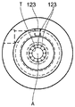
도 2는 본 발명의 일 실시형태에 따른 장치의 개략적인 도면으로, (a)는 실질적으로 수평 축선을 따르는 단면도이고, (b)는 본 발명의 장치의 칼럼을 아래쪽으로 바라 본 도면이다.
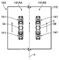
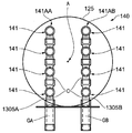
도 3은 도 1에 도시되어 있는 장치에서 채용하고 있는 초음파 발생기의 어레이를 설명하는 개략적인 도면으로, (a)는 측면도이고, (b)는 본 발명 장치의 칼럼을 따라 유동하는 유체의 유동 방향을 따라 바라 본 도면이다.
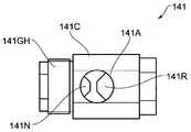
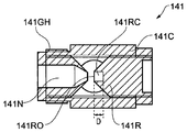
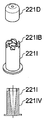
도 4의 (a)는 본 발명의 일 실시형태에 따른 장치에 사용되기에 적합한 휘슬 장치의 측면도이고, (b)는 (a)에서의 방향과 동일한 방향을 따라 바라 본 단면도이다.
도 5는 본 발명의 다른 실시형태에 따른 변환기 부분을 도시하는 도면으로, (a)는 단면도이고, (b)는 평면도이다.
도 6은 도 5에 도시되어 있는 실시형태의 마이크로버블 발생기를 나타내는 도면이다.
도 7은 도 5에 도시되어 있는 실시형태의 초음파 발생기를 나타내는 도면이다.
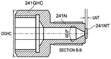
도 8은 도 7의 실시형태의 노즐 부재를 개략적으로 설명하는 도면으로, (a)는 측면도이고, (b)는 (a)의 방향 V1을 따라 바라 본 도면이고, (c)는 (b)에서 라인 B-B를 따르는 단면도이다.
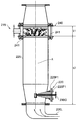
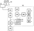
도 9는 발전소 보일러 배기가스를 처리하도록 배치되어 있는 본 발명의 일 실시형태에 따른 보일러 배기가스 처리 시스템의 개략적인 도면이다.
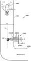
도 10은 내부에 도 6의 실시형태의 마이크로버블 발생기가 제공되어 있는 가스 리프트 펌프 장치의 다른 실시형태의 개략적인 도면이다. Various embodiments in various aspects of the invention will now be described, by way of example, with reference to the accompanying drawings, in which: Fig.
1 is a schematic diagram of an apparatus according to an embodiment of the present invention.
Fig. 2 is a schematic view of an apparatus according to an embodiment of the invention, wherein (a) is a section along a substantially horizontal axis, and (b) is a view of a column of the apparatus of the present invention.
Fig. 3 is a schematic view for explaining an array of ultrasonic generators employed in the apparatus shown in Fig. 1, wherein (a) is a side view, (b) shows a flow direction of a fluid flowing along the column of the inventive device Fig.
Fig. 4 (a) is a side view of a whistle device suitable for use in an apparatus according to an embodiment of the present invention, and Fig. 4 (b) is a cross-sectional view taken along the same direction as in Fig.
5 is a view showing a transducer portion according to another embodiment of the present invention, wherein (a) is a sectional view and (b) is a plan view.
Fig. 6 is a view showing the micro bubble generator of the embodiment shown in Fig. 5;
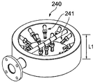
7 is a view showing the ultrasonic generator of the embodiment shown in Fig.
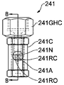
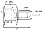
(A) is a side view, (b) is a view taken along a direction V1 of (a), and FIG. 8 (c) is a cross- Sectional view taken along line BB in Fig.
9 is a schematic diagram of a boiler exhaust gas treatment system in accordance with an embodiment of the present invention arranged to process a power plant boiler exhaust gas.
10 is a schematic view of another embodiment of a gas lift pump apparatus in which a micro bubble generator of the embodiment of Fig. 6 is provided therein.
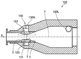
도 1은 본 발명의 일 실시형태에 따른 가스 변환 장치(100)를 개략적으로 설명하는 도면이다. 도 1에 도시되어 있는 장치(100)는 이산화탄소 공정 가스를 메탄 가스와 산소 가스로 변환하도록 구성되어 있다.1 is a view schematically illustrating a
장치(100)는 외부 공급원으로부터 장치(100)로 공급되는 이산화탄소 공정 가스를 압축하기 위한 압축기(105)를 구비한다. 압축기(105)에 의해 압축된 공정 가스는, 액체 보유 탱크(110) 내에 위치하는 장치(100)의 변환부(115)로 공급된다. 탱크(110)는 변환부(115)를 거의 침지하기에 충분한 양의 물을 저장한다. 물 외에 다른 액체도 유용될 수 있다. 가스 변환을 촉진하고, 부식을 억제하며 및/또는 박테리아의 성장을 억제하기 위해, 액체는 하나 혹은 그 이상의 첨가제를 함유할 수 있다.
변환부(115)는 직립 도관 혹은 칼럼(125)에 연결되어 있는 마이크로버블 발생부(120)를 구비한다. 마이크로버블 발생부(120)는 가스 유입구(130G)에서 이산화탄소 공정 가스를 유입하고, 액체 유입구(120L)에서 탱크(110)로부터 액체를 유입하도록 구성되어 있다. 아래에서 보다 자세하게 설명하는 바와 같이, 마이크로버블 발생부(120)는 마이크로버블을 발생시키고, 발생된 마이크로버블이 칼럼(125) 내로 상승하게 할 수 있다.The
칼럼부(125)의 하부에 초음파 발생부(140)가 제공되어 있다. 초음파 발생부(140)는 휘슬 장치(150) 어레이를 구비하며, 휘슬 장치는 압축된 가스가 휘슬 장치를 통해 가압될 때 초음파 에너지를 발생시킨다. 초음파 에너지는 칼럼부(125)를 통해 상승하는 마이크로버블의 캐비테이션을 야기하고, 결과적으로 이산화탄소의 적어도 일부가 메탄 및 산소로 변환되게 된다.And an
칼럼 내에서 초음파 발생부(140)를 통해 상승하는 가스는, 칼럼(140)의 자유 단부(140E)에서 배출되어, 탱크(110) 내의 액체의 액위(110LL) 위쪽의 탱크(11)의 헤드 공간(110H)으로 상승한다. 이에 따라, 메탄, 산소 그리고 변환되지 않은 이산화탄소의 혼합물이 헤드 공간(110H) 내에 포집된다. 일부 실시형태에서, 하나 이상의 탄화수소가 이들 가스에 부가하여 혹은 이들 가스 대신 헤드 공간(110H) 내에 수집될 수 있다.The gas rising through the
탱크(110)는, 실제 운용할 때에 탱크(110) 내에서 예상되는 액체의 최대 액위(level)보다 높은 레벨에서, 탱크(110)의 상부 벽(110U)을 통해 탱크(110)에 연결되어 있는 제1 및 제2 가스 유출부(110G1, 110G2)를 구비한다.The
제1 가스 유출부(110G1)는 가스 분리부(190)에 결합되어 있는 반면, 제2 가스 유출부(110G2)는 압축기(105)의 유입구에 결합되어 있다. 이에 따라, 제2 가스 유출부(110G2)를 통해 탱크(110)로부터 빠져 나가는 가스는 변환부(115)를 통해 재순환하게 된다. 이러한 기술적 특징은 헤드 공간(110H) 내에서의 이산화탄소의 농도를 낮춰줄 수 있게 하며, 이에 따라 지정된 양의 메탄을 얻기 위해, 헤드 공간(110H)에서 나와 분리기(190)에 의해 처리되어야 하는 가스의 양을 줄여주게 된다. 헤드 공간(110H) 내에서의 이산화탄소와 하나 이상의 다른 가스의 농도를 조절하기 위해, 헤드 공간(110H)으로부터 압축기(105)와 분리기(190)로 흐르는 가스의 상대적인 양이 조절될 수 있다. The first gas outflow portion 110G1 is coupled to the
마이크로버블 발생기(Microbubble generator)Microbubble generator
도 1의 장치의 마이크로버블 발생부는 사이클론(혹은 '사이클론식') 마이크로버블 발생기(120)이다. 마이크로버블 발생기(120)는 해당 발생기(120)의 버블 전단부(130) 내로 유입되는 액체 내에 스월(swirl)을 유도하도록 배치되어 있다. 버블 전단부(shear portion)(130)를 지나가는 액체 내에서 마이크로버블의 형성을 촉진하기 위해, 스월이 유도된다. The micro bubble generator of the apparatus of FIG. 1 is a cyclone (or 'cyclone')
도 2에 마이크로버블 발생부(120)가 보다 상세하게 도시되어 있다. 도 2a는 마이크로버블 발생부(120)의 실린더 축(A)과 직교하는 방향에서 바라본 발생부(120)의 단면도이다. 도 2b는 화살표 B를 따라 바라본, 실린더 축(A)을 따라 바라본 도면이다.The
발생부(120)에는, 탱크 내의 액체가 변환부(115) 내로 유입될 수 있도록 하기 위한 액체 유입구(120L)가 형성되어 있다. 도 2(a)로부터 알 수 있는 바와 같이, 유입구(120L)를 통해 발생부(120)로 유입되는 액체는 발생부(120)의 내벽에 대해 거의 접선 방향으로 유입된다. 이러한 기술적 특징은 발생부(120)를 통하는 액체의 유동에 스월이 발생되는 것을 촉진하게 한다.The generating
마이크로버블 발생부(120)를 통해 유동하는 액체는 초크 혹은 벤투리부(121)를 통해 유동하도록 가압된다. 벤투리부(121)는, 액체 유입구(120L)로부터 멀어짐에 따라 단면적이 감소하는 발생부(120) 부분의 위쪽에 해당하는 수렴부(converging portion)(C)와, 상기 수렴부(C)의 바로 하류에서 단면적이 거의 일정한 목부(throat portion)(T), 그리고 상기 수렴부(C)의 바로 하류에서 단면적이 증가하는 발산부(diverging portion)(D)를 구비한다.The liquid flowing through the
가스 유입구(123)는 벤투리부(121)의 목부(T) 내에 제공되며, 목부(T)를 통과하는 액체 내로 공정 가스가 분출될 수 있도록 배치되어 있다. 가스 유입구(123)는 목부(T) 둘레 주위에 이격된 위치에 제공되어 있으며, 이웃하는 가스 유입구는 서로가 거의 균일한 간격으로 위치하고 있다. 도시되어 있는 실시형태에서는 12개의 가스 유입구(123)가 제공되어 있다. 다른 수량의 가스 유입구(123)와 다른 배치의 가스 유입구(123)도 유용하다.The
실제 사용 시에, 벤투리부(121)를 통과하는 액체는 발생부(120)를 통과하는 액체 내에 형성되는 가스 버블을 전단(shear) 시키도록 배치되어 있다. 가스 유입구(123)를 통해 가스가 분사됨에 따라, 버블이 형성된다. 버블들이 전단됨에 따라, 이들 버블들의 크기는 정체된 상태의 액체에 형성되는 평형 상태에서의 가스 버블의 크기에 비해 작아지게 된다. 도 2에 도시되어 있는 형식의 마이크로버블 발생부(120)가 변환부(115) 내에서 마이크로버블이 안정적으로 유동할 수 있도록 하는 데에 매우 효과적이라는 것을 알 수 있었다.In actual use, the liquid passing through the
초음파 에너지 발생기(Ultrasonic energy generator)Ultrasonic energy generator
변환부(115)는, 실제 사용 시에, 액체 내에 공정 가스의 마이크로버블이 혼입된(entrained) 액체 유동을 마이크로버블 발생부(120)로부터 초음파 발생부(140)로 운송하도록 구성되어 있다.The converting
초음파 발생부(140)가 도 3에 상세하게 도시되어 있다. 도 3a는 초음파 발생부(140)의 측면도이고, 도 3b는 초음파 발생부(140)를 위로부터 축 A를 따라 바라본 도면이다. 초음파 발생부(140)는 각각이 휘슬 장치(141AA, 141AB)의 2개의 리니어 어레이를 포함한다. 각 어레이는 4쌍의 휘슬 장치(141)를 구비한다. 각 쌍의 휘슬 장치 중 하나는 실질적으로 수평 방향의 가스 공급 라인(GA, GB) 위쪽에 장착되어 있는 반면, 나머지는 가스 공급 라인 아래쪽에 장착되어 있다. 각 공급 라인(GA, GB)을 따르는 가스 유동은 휘슬 장치들(141)을 통해 흐르도록 가압되고, 가스는 칼럼(125) 내의 액체로 소진된다.The
도 4를 참조하면, 각 휘슬 장치(141)는 휘슬 바디를 제공하는 챔버(141C) 형태의 부분을 구비한다. 노즐 부재(141N)와 리셉터 부재(141R)는 휘슬 바디(141C)에 결합되어 있다. 휘슬 바디(141C)는, 리셉터 부재(141R)를 노즐 부재(141N)와의 관계에 있어서 거의 고정된 간격으로 그리고 거의 동축으로 지지하도록 배치되어 있다. 노즐 부재(141N)는, 각각 가스 공급 라인(GA, GB) 부분을 형성하는 가스 공급 헤드(141GH)에 결합되어 있는 것으로 도시되어 있다. Referring to Figure 4, each
노즐 부재(141N)는, 공정 가스 흐름이 리셉터 부재(141R)의 개구부(141RO)를 통해 리셉터 부재(141R)에 의해 획정되는 개방된 캐비티(141RC) 내로 지향되도록 배치되어 있다. 리셉터 부재(141R)는, 휘슬 바디(141C) 내에 탭이 형성되어 있는 구멍 내로 나사 체결되어 리셉터 부재(141R)가 휘슬 바디(141C)에 결합되도록 배치되어 있다. 이에 따라, 리셉터 부재(141R)는 챔버(141C)의 일 단부에 근접하여 배치되어 있다. 노즐 부재(141N)로부터 나와 캐비티(141RC)를 향하는 가스 유동은, 하트만-타입(Hartmann-type) 휘슬 장치 방식으로 초음파 에너지를 발생시키게 된다. 다른 휘슬 장치도 유용할 수 있다.The
리셉터 부재(141R)의 개구부(141RO)와 노즐 부재(141N) 사이의 거리는, 리셉터 부재(141R)의 회전에 의한 나사에 의해 조절될 수 있다.The distance between the opening 141RO of the
일부 장치에서, 리셉터 부재(141R)에 의해 획정되는 캐비티(141RC)의 깊이 D가 조절될 수 있다. 일부 장치에서, 이러한 깊이의 조절은 추가의 나사 조절에 의해 이루어질 수 있다. 예컨대, 캐비티(141RC)의 내부 기저면의 일 단부에 있는 나사의 위치를 조절함으로써 깊이 조절이 이루어질 수 있다. 이러한 기술적 특징은, 장치(141)에 의해 발생되는 음파 에너지의 양이 최적화될 수 있다는 이점이 있다. 일부 실시형태에서, 음파 에너지의 주파수(즉, 장치(141)에 의해 발생되는 음파(sound wave)의 주파수)는 깊이 D를 조절함으로써 조절될 수 있다.In some devices, the depth D of the cavity 141RC defined by the
휘슬 바디(141C)는 노즐 부재(141N) 및 리셉터 부재(141R)와 동축인 실질적으로 관상의 슬리브(tubular sleeve)이다. 상기 슬리브는 그 안쪽에 휘슬 바디(141C)로부터 나와 있는 노즐 부재(141N)로부터 칼럼(125) 내의 액체 내로 흐르는 가스 유동을 수용하기 위한 한 쌍의 구멍(141A)을 구비한다. 이에 따라, 휘슬 장치(141)는, 칼럼 내에 있는 액체 내로 가스 유동을 전달하는 가스 전달 장치로 기능한다. 액체 내에서 가스가 상승하고, 이러한 가스 리프트에 의해 변환부(115)를 통한 액체 펌핑이 이루어진다.The
초음파 발생기를 구동하기 위해 사용되는 가스는 구동 가스(drive gas)라고 호칭될 수 있다. 구동 가스는 공정 가스와 동일한 타입의 가스일 수 있고, 필요에 따라서는 동일한 공급원을 사용할 수도 있다. 또는, 구동 가스는 공정 가스와 다른 종류의 가스일 수도 있다.The gas used to drive the ultrasonic generator may be referred to as a drive gas. The driving gas may be the same type of gas as the process gas, and the same source may be used if necessary. Alternatively, the driving gas may be a gas other than the process gas.
일부 실시형태에서, 공정 가스는 연소 반응의 산물일 수 있다. 공정 가스는 약 13-14%의 이산화탄소 혹은 연소 조건에 따라서는 이와 다른 함량의 이산화탄소와, 잔부는 질소, 황산화물(SOx) 및 질소 산화물(NOx)로 구성될 수 있다. 예를 들면, 공정 가스는 석탄, 오일 혹은 가스-연소 발전소에서 운송될 수 있다. 일부 실시형태에서, 공정 가스는 선박의 플루 가스(flue gas)일 수 있다. 내연 기관에서 발생하는 배기 가스와 같이 이산화탄소를 함유하는 다른 공급원도 유용하다.In some embodiments, the process gas may be the product of a combustion reaction. The process gas may comprise about 13-14% of carbon dioxide or a different content of carbon dioxide depending on the combustion conditions and the balance of nitrogen, sulfur oxides (SO x ) and nitrogen oxides (NO x ). For example, process gases can be transported from coal, oil or gas-fired power plants. In some embodiments, the process gas may be a flue gas of the vessel. Other sources of carbon dioxide, such as exhaust gas from an internal combustion engine, are also useful.
일부 다른 실시형태에서, 구동 가스가 칼럼 내의 액체 내로 소진되지 않도록, 장치가 배치된다. 일부 실시형태에서, 구동 가스는 재가압되고 휘슬 장치(141)를 통해 재순환한다.In some other embodiments, the apparatus is arranged such that the drive gas is not exhausted into the liquid in the column. In some embodiments, the driving gas is re-pressurized and recycled through the
변환 반응Conversion reaction
이산화탄소 마이크로버블이 변환부(110)의 칼럼(125) 내에 있는 초음파 에너지에 노출되면, 마이크로버블이 붕괴되어 가스가 급속히 그리고 극심하게 가열되며, 자유 라디칼이 발생하게 되는 것으로 이해된다. 아래의 화학식에 따라 이산화탄소가 메탄과 산소로 변환하게 되는 것으로 믿어진다.It is understood that when the carbon dioxide microbubble is exposed to the ultrasonic energy in the
반응식은 다음의 화학식으로 표현될 수 있다.The reaction formula can be expressed by the following formula.
CO2 + 4H2O = CH4 + 2H2O + 2O2 CO 2 + 4H 2 O = CH 4 + 2H 2 O + 2O 2
또는,or,
CO2 + 2H2O = CH4 + 2O2 CO 2 + 2H 2 O = CH 4 + 2O 2
일부 실시형태에서, 반응을 촉진시키기 위해 촉매가 사용될 수 있다. 촉매는 특히 탱크(110) 내에 있는 액상 매체 내에 부유(suspended)되는 촉매 입자 형태로 제공될 수 있다. 일부 실시형태에서, 촉매 입자들은 철 혹은 철산화물을 함유한다. 일부 실시형태에서, 헤마타이트(hematite) 입자 혹은 헤마타이트-함유 입자들이 유용하다.In some embodiments, a catalyst may be used to promote the reaction. The catalyst may be provided in the form of catalyst particles suspended in the liquid medium, particularly in the
본 발명의 실시형태들은, 이산화탄소와 같이 환경에 유해할 수 있는 하나 이상의 가스가, 상대적으로 간단한 방식으로 그리고 에너지 효율적인 공정으로 유용한 형태의 가스로 변환될 수 있다는 특징을 갖는다. 가압된 가스 유동에 의해 초음파 에너지가 발생함으로써, 전기식 변환 장치와 같이 다른 방식으로 초음파 에너지를 발생시키는 공정에 비해 상대적으로 견고(robust)하면서도 탄성(resilient) 있는 장치가 제공될 수 있게 된다.Embodiments of the present invention are characterized in that one or more gases that can be harmful to the environment, such as carbon dioxide, can be converted into a useful form of gas in a relatively simple manner and in an energy efficient process. By generating ultrasonic energy by the pressurized gas flow, a relatively robust and resilient device can be provided as compared to a process of generating ultrasonic energy in other ways like an electric conversion device.
본 발명의 실시형태들은, 발전소에서 방출되는 연소 가스 내에 존재하는 이산화탄소를 산소 및 메탄 가스로 변환하는 데에 유용하다. 본 발명의 일부 실시형태에서 발생되는 산소 가스는 주위 환경으로 방출되거나 산소 가스 용기에 저장되어 예컨대 산업용 공정 가스로 사용되거나 판매될 수 있다.Embodiments of the present invention are useful for converting the carbon dioxide present in the combustion gas emitted from a power plant into oxygen and methane gas. The oxygen gas generated in some embodiments of the present invention may be released to the ambient environment or stored in an oxygen gas vessel to be used or sold, for example, as an industrial process gas.
발생된 메탄 가스는 연료로 사용되거나 혹은 화학물 처리와 같이 다른 적당한 목적을 위해 사용될 수 있다.The generated methane gas can be used as fuel or for other suitable purposes such as chemical treatment.
일부 실시형태에서, 칼럼(125)을 통과하는 가스의 재순환이 수행되지 않는 것으로 이해된다. 일부 실시형태에서, 가스가 재순환되지 않고 분리기(190)로 공급된다. 일부 실시형태에서, 칼럼(125)을 따라 통과하는 가스가 분리기(190)로 운송되지 않는다. 일부 실시형태에서, 가스가 저장 탱크 내에 저장된다.In some embodiments, it is understood that recirculation of the gas passing through the
본 발명의 일부 실시형태에 따른 가스 변환 장치는 태양 에너지와 같은 재생 에너지원에 의해 생성되는 전기 에너지로 작동될 수 있는 것으로 이해된다. 일부 실시형태에서, 초음파 에너지 발생기의 휘슬 장치가 압축기(105)를 필요하지 않게 공정 가스를 압축하지 않고서도 작동될 수 있을 정도로 공정 가스가 충분히 높은 압력으로 장치에 공급될 수 있는 것으로 이해된다. 또한, 헤드 공간(110H)에서 인출된 후 칼럼(125)을 통해 재순환하는 가스를 압축하기 위한 압축기에 동력을 공급할 수 있을 정도로, 공정 가스가 충분히 높은 압력으로 공급될 수 있다. 이에 의해, 압축기(105)를 작동하는 데에 소량의 추가 동력만이 필요하거나 혹은 전혀 필요하지 않게 된다.It is understood that the gas conversion device according to some embodiments of the present invention may be operated with electrical energy generated by a renewable energy source such as solar energy. In some embodiments, it is understood that the process gas can be supplied to the apparatus at sufficiently high pressure such that the whistle device of the ultrasonic energy generator can be operated without compressing the process gas without the need for the
일부 실시형태에서, 헤드 공간(110H) 내에 수집된 가스는, 일부 실시형태에서 적어도 메탄과 산소의 혼합물일 수 있고, 이 혼합물은 연료로 사용되거나 혹은 메탄과 산소를 분리하지 않은 상태로 산업용 공정에 사용될 수 있는 형태일 수 있다. 헤드 공간(110H) 내에 잔류 이산화탄소 공정 가스가 존재하는 실시형태에서, 압축기(105)를 통해 가스가 재순환함에 따라, 가스가 연료 혹은 특정 산업용 공정에 사용될 수 있을 정도로 이산화탄소의 농도가 감소될 수 있다. 다른 장치도 또한 유용하다.In some embodiments, the gas collected in the
본 발명의 일부 다른 실시형태에서, 다른 마이크로버블 발생기 및/또는 다른 초음파 에너지 발생기가 채용될 수 있다.In some other embodiments of the invention, other micro bubble generators and / or other ultrasonic energy generators may be employed.
변환부에 대한 하나의 다른 실시형태가 도 5에서 도면부호 215로 도시되어 있다. 도 5의 변환부(215)는 다른 마이크로버블 발생기(220)와 다른 초음파 에너지 발생기(240)를 구비한다. 도 5의 실시형태에서, 도 1의 실시형태에서의 구성과 유사한 구성에 대해서는 도면부호에 100을 더하여 표기하였다.One alternative embodiment of the transformer is shown at 215 in FIG. The
도 5는 도 5b의 단면 A-A에서 바라본 변환부(215)를 도시하고 있다. 도 5b는 변환부(215)의 평면도이다. 변환부(215)는 칼럼(225)을 구비하고, 칼럼의 베이스에는 칼럼의 하단부로부터 칼럼 내로 액체를 뽑아 올리거나 펌핑될 수 있도록 액체 유입구(220L)를 구비한다.FIG. 5 shows the
도 5a의 실시형태는, 길이 L1이 약 160mm, 길이 L2가 약 1100mm의 크기이다. 다만, 다른 크기도 유용할 수 있다.In the embodiment of Fig. 5A, the length L1 is about 160 mm, and the length L2 is about 1100 mm. However, other sizes may be useful.
마이크로버블 발생기(220)는 액체 유입구(220L) 위쪽에 제공되어 있으며, 마이크로버블 발생기(220)를 칼럼(225)에서 대응 플랜지(225F1)에 결합시키도록 배치되어 있는 플랜지(220F1)를 포함한다. 칼럼(225)이 바람직한 다른 방위로 배치될 수 있다는 점을 이해해야 한다. 본 실시형태에서, 칼럼(225)은 거의 직립 형태로 위치하고 있으며, 수직 방향으로 칼럼(225)의 실린더 축 A를 구비한다. 도 5의 실시형태에서, 마이크로버블 발생기(220)의 플랜지(220F1)는 거의 수직 평면 내에 자리하고 있다.The
도 6a에 도시되어 있는 바와 같이, 마이크로버블 발생기(220)는 발생기를 관통하는 가스 도관(230GB)을 구비하며, 플랜지(220F1)에 고정방식으로 결합되어 있다. 가스 도관(230GB)은 플랜지(220F1)와 거의 수직으로 그리고 플랜지(220F1)와 동축으로 플랜지(220F1)로부터 연장하고 있으며, 붐-유사 구조물을 획정한다. 붐-유사 구조물은 붐의 자유 단부에서 가스 버블러 장치(221)를 지지한다. 한 쌍의 강직한 웹 부분(230W)이 플랜지(220F1)의 일 단부에 부착되어 있으며, 가스 도관(230GB)의 거의 전장을 따라 연장하고 가스 도관(230GB)에 결합되어 있다. 웹 부분(230W)은 가스 도관(230GB)의 바로 위 그리고 아래에 위치하고 있고, 가스 도관(230GB)을 보강 및 강화하는 기능을 한다. 칼럼(225) 내의 가스 도관(230GB)을 통과하는 액체 유동이 가스 도관(230GB)에 큰 힘을 가할 수 있다는 점을 이해할 수 있을 것이다. 이에 따라, 웹 부분(230W)이 가스 도관(230GB)이 벤딩되는 것을 적어도 어느 정도 방지할 수 있는 기능을 수행하게 된다. 웹 부분(230W)은 칼럼(225)의 실린더 축 A와 평행한 방향을 따라 액체 유동이 거의 평행하게 되도록 배치되어 있다. As shown in FIG. 6A, the
버블러 장치(221)는 아래쪽이 개방되어 있는 캐비티를 획정하는 하우징(221H)을 구비한다. 캐비티 내에는 내부형상이 반경이 있는 돔-형 혹은 컵-형 부재인 중공형 돔 부재(221D)가 제공되어 있다. 돔 부재(221D)는 버블러 장치(221)로 유입되는 공정 가스 유동 위에 위치하며, 아래에 설명되어 있는 바와 같이, 버블러 장치(221) 내로 유동하는 채널링 가스가 삽입 부재(221I)를 향해 아래쪽으로 유동하도록 보조하게 배치되어 있다. 돔 부재(221D)의 반경형태의 내부 형상은, 돔 부재(221D) 내로 공정 가스가 유동할 때, 하우징(221H) 내에서 와류가 발생하는 것을 줄여주게 된다.The
버블러(221)로 유입되는 공정 가스는 거의 원통형이며, 버블러(221)의 하우징(221H) 내에 슬라이딩 조립되게 배치되어 있는 중공형 삽입 부재(221I)를 통해 아래쪽으로 유동하게 된다. 중공형 삽입 부재(221I)는 (도시되어 있는 방위와 관련하여) 아래쪽으로부터 도입되어 조립된다. 삽입 부재(221I)에는, 삽입 부재의 상부 둘레 림 주위에 균일한 간격으로 배치되어 있는 5개의 스월 혹은 소용돌이-유도 강직성 블레이드 요소(221IB)가 제공되어 있다. 5개 이외의 다른 수량의 블레이드 요소(221IB)도 유용할 수 있다. 블레이드 요소(221IB)는, 블레이드 요소(221IB)의 충돌 면들이 도관(230GB)으로부터 하우징(221H) 내로 통과하는 공정 가스의 유로 내에 바로 위치하도록 가스 도관(230GB)의 종 방향 실린더 축에 정렬되어 있다. 이에 따라, 버블러(221)로 유입되는 공정 가스는 블레이드 요소(221IB)의 면들 바로 위에서 충돌하여, 버블러(221) 내에서 공정 가스가 스월을 형성하기 시작한다. 즉, 공정 가스가 소용돌이-유사 유로를 거치게 된다. 공정 가스는, 삽입 부재(221I)에 의해 획정되는 유체 통로를 통해 아래쪽으로 유동하도록 가압된다. 유체 통로는 통로의 위쪽에서부터 아래쪽으로 통로가 좁아지게 안쪽으로 테이퍼져 있는 원추형(cone) 이다. 그 결과, 블레이드 요소(221IB)로부터 멀어지며 아래쪽으로 유동하는 공정 가스의 속도가, 블레이드 요소(221IB)로부터의 거리에 따라 증가한다.The process gas flowing into the
삽입 부재(221I)의 하단부에서, 원통형의 구멍 캡 부재(221AP)가 제공되어 하우징(221H)의 자유 단부 위에 나사 고정되어, 삽입 부재(221I)를 하우징(221H) 내에 유지시키게 된다. 구멍 캡 부재(221AP)는 해당 구멍 캡 부재(221AP)의 헤드부(221APH) 내에 형성되어 있는 구멍(221APA)을 구비한다. 구멍(221APA)은 하우징(221H)과 동축이다. 구멍(221APA)은, 공정 가스가 버블러(221)로부터 빠져나와 버블러(221)가 침지되어 있는 액체 내로 유입되도록 배치되어 있다. 공정 가스가 소용돌이 유동을 하고, 삽입 부재(221I)를 따라 가속되도록 실질적으로 가압되게 하는 이러한 구성은, 공정 가스가 칼럼(225) 내의 액체 내로 비교적 고속으로 그리고 고강도의 스월 혹은 스핀을 가진 상태로 분출될 수 있도록 하는 특징을 갖는다. 본 출원인은, 이러한 방식으로 액체 내로 가스가 분출되어 형성되는 가스 버블들이 특히 작은 크기, 일부 실시형태에서는 직경이 50 마이크로미터 미만의 작은 크기로 되도록 하여, 칼럼(225) 내의 액체와 가스가 잘 혼합될 수 있게 한다는 것을 알 수 있었다. 또한, 칼럼(225)을 통해 위쪽으로 유동하는 액체 유동 내에서, 가스 버블들이 초음파 에너지 발생기(240)를 향해 위쪽으로 뽑아 올려지거나 혹은 가압됨에 따라, 가스 버블들이 안정적인 상태를 유지하고, 거의 동일한 크기를 유지한다는 것을 알 수 있었다.At the lower end of the insertion member 221I, a cylindrical hole cap member 221AP is provided and screwed onto the free end of the
도 6의 실시형태에서, 버블러(221)의 실린더 축(이는 삽입 부재(221I)와 구멍 캡(221AP)의 실린더 축과 거의 일치함)이 칼럼(225)의 실린더 축과 거의 일치하도록, 버블러(221)가 칼럼(225)과 거의 동축으로 제공된다. 다른 장치도 유용할 수 있다. 그러나, 버블러(221)를 칼럼(225)에 대해 거의 중앙부에 위치하도록 버블러를 배치하면, 칼럼의 단면적에 대해서 마이크로버블이 비교적 균질하게 유동할 수 있다는 것을 알 수 있었다.In the embodiment of Fig. 6, the
도 7은 초음파 에너지 발생기(240)를 좀 더 상세하게 도시하고 있다. 도 7a는 초음파 에너지 발생기(240)의 3차원 도면이고, 도 7b는, 초음파 에너지 발생기(240)의 일부를 형성하는 19개의 휘슬 장치(241) 중 하나의 외형도이다. 도 7c는 도 7b의 섹션 B-B를 따라 바라본 휘슬 장치(241)를 나타내고, 도 7d는 휘슬 장치(241)의 3차원 도면이다. 도 7의 장치에서 도 4의 장치와 유사한 구성요소에 대해서는 도면부호 100을 더한 유사한 도면부호로 표기하였다.FIG. 7 shows the
도 7a로부터 알 수 있는 바와 같이, 16개의 휘슬 장치가 변환부(215)의 칼럼(225) 주위에 원주방향으로 배치되어 있고, 3개의 휘슬 장치가 칼럼(225)의 직경을 따라 이격되는 위치에 배치되어 있으며, 이들은 실제 사용 시에 칼럼(225)을 통과하는 액체 유동 방향의 상류를 향하고 있다. 다른 수량의 휘슬 장치와, 휘슬 장치의 다른 배치도 유용할 수 있다. 도시되어 있는 실시형태에서, 휘슬 장치(241)는, 거의 모든 유체가 적어도 하나의 휘슬 장치(241)의 바디 부분의 50mm 내에서 칼럼(225)을 따라 통과하도록, 배치되어 있다. 이렇게 함으로써, 유체 내에 동반되어 있는 마이크로버블들이 충분히 높은 강도의 초음파 방사에 노출될 수 있게 된다. 이와 다른 거리도 물론 유용할 수 있다.As can be seen from FIG. 7A, sixteen whistle devices are arranged in the circumferential direction around the
도 4에 도시되어 있는 실시형태에서의 휘슬 장치(141)에서와 같이, 도 7의 휘슬 장치(141)는 탭이 형성되어 있는 휘슬 바디를 획정하는 챔버(241C)를 구비한다. 노블 부재(241N)와 리셉터 부재(241R)들이 각각 나사에 의해 휘슬 장치 바디(241C)에 결합되어 있다. 도시되어 있는 실시형태에서, 리셉터 부재(241R)의 거의 전부가 휘슬 바디(241C) 내에 수용되어 있으며, 노즐 부재(241N)에 대해 거의 동축 방향으로, 실질적으로 이격되되 간격이 고정되어 있다. 도시되어 있는 실시형태에서, 노즐 부재(241N)는, 가스 공급 헤드 커플링(241GHC)과 동일한 부품과 일체로 형성되어 있다. 커플링(241GHC)에는, 노즐 부재(241N)가 가스 공급 헤드에 결합될 수 있도록 암나사가 형성되어 있다. 숫나사는 노즐 부재(241n)가 휘슬 바디(241C)에 결합될 수 있게 한다.As in the
도 8은 하우징(241C)으로부터 분리되어 있는 노즐 부재(241N)와 가스 공급 헤드 커플링(241GHC)을 도시하고 있다. 도 8은 거의 축척에 맞추어 도시되었고, 본 실시형태에서 길이 L1은 40mm이고, 직경 DGHC는 약 31mm이다. 다른 치수도 물론 유용하다.Figure 8 shows the
도 8에 도시되어 있는 바와 같이, 노즐 부재(241N)는 와류발생기(tubulator)(241NT)로 표기될 수 있는, 유동-분할 베인 요소를 구비한다. 와류발생기(241NT)는 실질적으로 평탄형의 직사각 요소로, 노즐 부재(241N)로부터 나오는 가스 유동을 두 분류로 분할하도록 배치되어 있다. 와류발생기(241NT)를 설치함으로써, 휘슬 장치(241)에 의해 발생되는 초음파 에너지의 주파수를 거의 일정하면서도 재현가능한 주파수로 튜닝할 수 있다는 것을 알 수 있었다. 일부 실시형태에서, 초음파 에너지의 주파수는 약 20kHz 내지 약 30kHz이고, 필요에 따라서는 약 20kHz 내지 약 26kHz일 수 있다. 30kHz보다 크거나 및/또는 20kHz보다 작은 주파수도 유용할 수 있다. (실제 사용 시에 칼럼(125)와 거의 일치하는) 노즐 부재(241N)의 종 방향 축 A에 대한, 와류발생기(241NT)의 길이 LNT는 약 1mm이다. 이와 다른 크기도 유용할 수 있으며, 통상의 기술자라면 실험적으로 와류발생기(241NT)의 적정 길이를 결정할 수 있을 것이다.As shown in FIG. 8, the
노즐 부재(241N)는 가스 유동이 노즐 부재(241N)를 통과하여 리셉터 부재(241R)에 의해 획정되는 개방 캐비티(241RC) 내로 유입되도록 지향하고 있다. 가스 유동이 노즐 부재(241N)로부터 개방 캐비티(241RC) 내로 유입됨에 따라, 하트만-타입 휘슬 장치 방식으로 초음파 에너지가 발생되게 된다. 휘슬 장치(241)를 통해 유동하는 가스가 휘슬 바디(241C) 내의 구멍(241A)을 통해 장치로부터 유출됨에 따라, 칼럼(225) 내에서 가스를 리프트 시킨다.The
도시되어 있는 실시형태에서, 휘슬 장치(241)는 약 20 내지 약 26kHz 사이의 주파수를 갖는 초음파 에너지를 발생시키도록 튜닝될 수 있다. 전술한 바와 같이, 일부 실시형태에서 주파수가 높을수록 유용할 수 있다. 통상의 기술자라면 휘슬 장치들을 구동하기에 최적의 가스 압력과, 적당한 주파수와 진폭의 초음파 에너지를 발생시키기 위한 노즐 부재(241N)와 리셉터 부재(241R) 사이의 최적 거리를 결정할 수 있다는 점을 이해할 수 있을 것이다. 본 출원인은, 휘슬 장치(241)에 있어서, 신선한 물 표면으로부터 깊이가 2m 혹은 이보다 다소 낮은 깊이에서, 공정 가스 압력이 1-4바, 필요에 따라서는 1-5바 사이에서, 노즐 부재(241N)와 캐비티(241RC) 사이의 거리를 적당하게 조절함으로써 적당한 진폭과 주파수의 초음파 에너지가 발생될 수 있다는 것을 알 수 있었다. 리셉터 부재(241R)와 노즐 부재(241N) 사이의 거리는 리셉터 부재(241R)의 회전에 따른 나사 회전에 의해 조절될 수 있다. 일부 실시형태에서, 휘슬 장치(141)를 구동하기 위한 구동 가스가 약 1.5바의 압력으로 액체 저장 탱크(110) 내의 액위의 2m 아래 깊이에 있는 휘슬 장치(141)에 공급된다. 일부 실시형태에서는, 5바 보다 큰 압력이 유용할 수 있다.In the embodiment shown, the
본 발명의 실시형태들은 변환부(115, 215)의 칼럼 내의 액체 내에서 매우 효율적으로 마이크로버블을 발생시킬 수 있다는 것을 알 수 있었다. 마이크로버블들이 초음파 에너지 발생기에 의해 발생된 초음파 에너지를 받으면, 마이크로버블들의 캐비테이션이 일어난다. 마이크로버블들이 이산화탄소를 함유하는 경우, 캐비테이션이 마이크로버블을 붕괴시키고, 이에 의해서 위에서 설명한 바와 같이 이산화탄소가 탄화수소 가스와 산소로 변환되는 것으로 생각된다.It has been found that the embodiments of the present invention can generate micro bubbles very efficiently in the liquid in the columns of the
일부 실시형태들에서, 메탄 가스가 발생될 수 있다. 일부 실시형태들에서, 메탄 가스에 부가하여 혹은 메탄 가스 대신에 하나 이상의 다른 탄화수소 화합물이 발생될 수 있다. 예를 들면, 일부 실시형태에서, 메탄에 부가하여 혹은 메탄 대신에 메탄올 및/또는 에탄올이 생성될 수 있다. 일부 실시형태에서, 에탄, 프로판 및 하나 이상의 다른 알칸 물질이 생성될 수 있다. 특정 생성물의 형성을 촉진하기 위해, 하나 이상의 촉매 소재들이 액체 보유 탱크(110, 210) 내에 제공될 수 있다. In some embodiments, methane gas may be generated. In some embodiments, one or more other hydrocarbon compounds may be generated in addition to, or instead of, methane gas. For example, in some embodiments, methanol and / or ethanol may be produced in addition to, or instead of, methane. In some embodiments, ethane, propane, and one or more other alkane materials may be produced. One or more catalytic materials may be provided in the
일부 실시형태에서, 비-탄화수소 가스만이 생성될 수도 있다.In some embodiments, only non-hydrocarbon gas may be produced.
도 9는 이산화탄소를 포함하는 공정 가스를 메탄 가스와 산소 가스로 변환하도록 구성되어 있는 보일러 배기 가스 변환 장치(300)에 연결되어 있는 석탄, 오일 혹은 가스-점화 발전소를 개략적으로 나타내는 도면이다. 장치(300)는 액체 보유 탱크(310)를 구비하며, 액체 보유 탱크 내에는 도 5a 내지 도 8을 참고로 하여 위에서 설명한 변환부(215) 세 개가 제공되어 있다. 변환부(215)는 1, 2, 4, 5, 10 또는 다른 적당한 수량으로 이루어질 수 있다.9 is a view schematically showing a coal, oil or gas-fired power plant connected to a boiler exhaust
장치(300)는 발전소 보일러 배기 가스 형태의 공정 가스를 받아들이고, 공정 가스가 초기에 가스 냉각 스크러버(381)를 통과하도록 구성되어 있다. 스크러버(381)는 수냉 시스템으로 가스를 냉각시키며, 더불어서 가스 내에 현탁되어 있는 그을음 입자와 같은 입상 물질들을 제거한다. 일부 실시형태에서, 가스를 구성하는 하나 이상의 다른 성분들 예컨대 SOx 및/또는 NOx 같은 성분들이 제거될 수 있다.The
그런 다음, 공정 가스는 가스 압축 시스템(382)을 통과하고, 그런 다음 변환부(215)로 바로 들어가거나 아니면 질소 분리 시스템(383)을 지나 변환부(215)로 들어간다. 질소 분리 시스템(383)은 공정 가스에서 질소 가스를 분리하도록 배치되어 있다. 질소 분리 시스템(383)은 질소를 분리시키도록 구성된 막 분리 시스템을 포함할 수 있으며, 필요에 따라서는 중공형 섬유 막 분리(HFMS) 시스템을 포함할 수 있다. 분리된 질소는 질소 가스 배출 취급 시스템(384)을 통과하며, 이 질소 가스 배출 취급 시스템에 의해 질소가 대기로 배출되거나, 저장되고 혹은 하나 이상의 다른 목적을 위해 사용된다. 나머지 가스는 변환부(215)로 안내된다.The process gas then passes through a
위에서 설명한 바와 같이, 액체 보유 탱크는 3개의 변환부(215)를 구비하며, 각 변환부는 액체 보유 탱크(310) 내의 액체 내에 침지되어 있는 칼럼(225) 내에서 공정 가스 마이크로버블을 발생시키도록 배치되어 있다. 변환부(215)는 마이크로버블들이 고 강도의 초음파 방사를 받도록 배치되어 있다. 적어도 하나 이상의 변환부(215)의 칼럼(225)을 통과한 가스는 액체 보유 탱크(310)로부터 취출되어 가스 압축 시스템(388)으로 안내된다. 장치(300)는, 공급되는 가스가 바로 가스 압축 시스템(388)으로 안내되도록 하거나 혹은 질소 분리 시스템(386)을 경유하여 가스 압축 시스템(388)으로 안내되도록 배치되어 있다. 가스가 질소 분리 시스템(386)을 경유하여 가스 압축 시스템(388)으로 안내되도록 장치(300)가 작동하는 경우, 질소 분리 시스템(386)에 의해 가스에서 분리된 질소는 질소 가스 배출 취급 시스템(387)으로 안내되어, 질소가 대기로 배출되거나 저장되며 혹은 하나 이상의 다른 목적을 위해 사용된다.As described above, the liquid holding tank has three
일부 사용 시나리오에서, 보일러 배기 가스 변환 장치(300)는, 해당 시스템을 통과하여 가스 압축 시스템(388)으로 유동하는 가스가 2개의 가스 분리 시스템(383, 386) 중 하나의 가스 분리 시스템만을 통과하도록 배치되어 있다. 일부 다른 시나리오에서는, 장치(300)는 가스가 2개의 가스 분리 시스템(383, 386) 모두를 통과하도록 배치되어 있다.In some use scenarios, the boiler exhaust
일부 실시형태에서, 장치(300)는 2개의 가스 분리 시스템(383, 386) 중 하나의 가스 분리 시스템만을 구비한다. 일부 실시형태에서, 장치(30)는, 가스가 어떠한 가스 분리 시스템(383, 386)도 통과하지 않도록 배치되어 있다.In some embodiments, the
가스 압축 시스템(388)을 통과한 가스는 계속해서 메탄 분리기(389)로 안내되어, 분리기(389)로 유입되는 가스에서 메탄을 분리한다. 분리된 메탄은 메탄 저장 탱크(390) 내에 저장된다.The gas that has passed through the
메탄이 분리된 가스는 분리기(389)로부터 산소 분리기(391)로 안내되어, 가스로부터 산소가 분리된다. 분리된 산소는 산소 저장 탱크(392) 내에 저장된다. 산소 분리기(391)에서 산소가 분리된 가스는 배출되기 전에 추가로 처리될 수 있다.The methane separated gas is led from the
이에 따라, 장치(300)는 발전소 보일러 배기 가스, 특히 이산화탄소가 함유되어 있는 발전소 보일러 배기 가스로부터 탄화수소와 산소를 발생 및 분리시키는 데에 사용될 수 있다.Accordingly, the
질소 분리 시스템(383, 386) 각각은 가스가 막 분리기 같은 분리기 부분을 통과하기 위해, 가스를 압축하기 위한 압축기를 구비할 수 있다는 점을 이해해야 한다.It should be appreciated that each of the
본 발명의 실시형태들에서, 가스의 분리는 막 분리기(membrane separator), 예컨대 중공형 섬유 막 분리기 HFMS 혹은 임의의 다른 적당한 분리기에 의해 수행될 수 있다. In embodiments of the present invention, gas separation may be performed by a membrane separator, such as a hollow fiber membrane separator HFMS or any other suitable separator.
일부 실시형태에서, 이산화탄소를 탄화수소 연료로 변환시키기 위해 장치가 제공된다. 그 장치는 전기 에너지로 구동된다. 전기 에너지를 주로 소모하는 장치는 가스 압축기, 가스 분리 장치 및 장치를 제어하기도록 배치되어 있는 제어 모듈이다. 이산화탄소를 탄화수소 가스, 액체 혹은 고체로 변환하기 위해 장치가 사용될 수 있다. 장치는 태양열 에너지, 지열 에너지, 풍력 에너지, 파도 혹은 조수 에너지 같은 재생 에너지원에서 생성되는 전기 에너지를 사용한다. 본 실시형태에서, 장치는 이산화탄소를 메탄으로 변환하도록 배치되어 있다. 일부 실시형태에서, 장치는 지역에 혹은 상업용 빌딩에 설치되기에 적당할 수 있으며, 예컨대 씻거나 요리하기 위해 필요한 경우 물을 데우거나 다른 물질을 데우는 데에 메탄이 사용된다. 일부 실시형태에서, 발생된 이산화탄소가 다시 장치로 회수되어 다시 메탄으로 변환될 수 있다. 다른 장치도 또한 유용할 수 있다.In some embodiments, an apparatus is provided for converting carbon dioxide to hydrocarbon fuel. The device is driven by electrical energy. The main consuming electrical energy is the control module, which is arranged to control the gas compressor, the gas separation device and the device. Devices can be used to convert carbon dioxide to hydrocarbon gases, liquids, or solids. The device uses electrical energy generated from renewable energy sources such as solar energy, geothermal energy, wind energy, wave or tidal energy. In the present embodiment, the apparatus is arranged to convert carbon dioxide to methane. In some embodiments, the device may be suitable for installation in a local or commercial building, for example, methane is used to heat water or other materials when needed for washing or cooking. In some embodiments, the generated carbon dioxide can be recovered back to the apparatus and converted back to methane. Other devices may also be useful.
일부 실시형태에서, 장치는, 재생 에너지 포획 기기 혹은 솔라 패널, 파워 컨버터 및 제어 전자부품을 구비하는 솔라 광전지 에너지 발생기 같은 장치와 조합되어 제공될 수 있다.In some embodiments, the apparatus may be provided in combination with a device such as a renewable energy capture device or a solar photovoltaic energy generator with a solar panel, a power converter and control electronics.
도 10은, 예컨대 배 혹은 다른 수상-주행 선박 같은 선박의 액체 저장 혹은 밸러스트 탱크 내에서 액체를 순환시키기 위해, 수행의 유해한 종(ANS)을 죽일 목적으로 사용되는, 가스 리프트 펌프 장치(450)의 일예로 도 5 및 도 6에 도시되어 있는 실시형태의 신규의 마이크로버블 발생기(200)의 용도를 보여주는 개략적인 도면이다. 마이크로버블 발생기(220) 혹은, 본 명세서에 정의되어 있는 본 발명의 범위 내에 속하는 다른 실시형태들이, WO2013/093527호(해당 문헌은 참고로 본 명세서에 통합됨)에 개시되어 있는 장치를 포함하여, 다른 실시형태들 및 가스 리프트 장치를 구성하는 데에 사용될 수 있다. Fig. 10 is a side elevational view of a gas
도 10에 도시되어 있는 바와 같이, 가스 리프트 펌프 장치(450)는 도 5에 도시되어 있고 도 6에 상세하게 확대되어 도시되어 있는 바와 같은 신규한 마이크로버블 발생기(220)와, 일반적으로 (실제 사용 시에) 수직 가스 리프트 칼럼(460) 내에 제공되는 음파 에너지 발생기(400)를 포함한다. 음파 에너지 발생기(400)는 본 발명의 다른 실시형태와 본 발명의 다른 양태에서 사용되는 것과 같은 임의의 음향 에너지 발생기일 수 있으며, WO2013/093527의 실시형태에 도시 및 설명되어 있는 것과 같은 유체 전달 장치/음파 에너지 발생기와 조합될 수 있다. 칼럼(460)에는 예컨대 (안에 장치가 제공되는 선박의 밸러스트 탱크 내의 물과 같은) 물인 액체로 채워지며, 액체는 가스 리프트에 의해 유동 L로 펌핑된다.As shown in Figure 10, the gas
마이크로버블 발생기(220)는 버블러(221)를 통해 칼럼(460) 내로 이산화탄소 같은 가스 P가 분출되도록 작동된다. 배출되는 가스 유동은 음파 에너지 발생기(400)를 향해 상승한다. 가스가 버블러(221)를 빠져나와 칼럼(460) 내에서 음파 에너지 발생기(400)를 향해 상승함에 따라, (칼럼(460)의 단면적 D1에 대해) 가스 마이크로버블 유동의 균질성(homogeneity)을 향상시키기 위해, 버블러(221)는 칼럼(460) 내에서 칼럼과 거의 동축으로 위치하는 것이 바람직하다(즉 공통의 종 방향 축 X를 따라 정렬). 장치(450)는, 음파 에너지 발생기(400)와 버블러(221)에 의해 칼럼 내로 분출되는 가스로 인한 가스 리프트 효과에 의해, 흡입 튜브(460H)로부터 물 혹은 다른 액체 L을 칼럼(460)을 통해 펌핑하도록 작동한다. 위에서 설명한 바와 같이, 일부 실시형태에서, 음파 에너지 발생기(400)가 음파 에너지를 발생하도록 하는 데에 사용되는 구동 가스는 가스 리프트 칼럼(460) 내로 소진되기 보다는 장치(450)에 의해 재순환될 수 있다.The
도 6과 관련하여 위에서 설명한 바와 같은 동일한 방식으로, 버블 발생기(220)의 버블러(221)에서 가스 버블들이 생성되어 방출된다. 가스 P가 버블러(221)를 통해 도관(230GB)을 경유하여 분출되어 바닥(출구)에서 배출될 때, 전단력을 받아 버블들의 크기가 미크론-단위 레벨로 감소된다. In the same manner as described above with respect to FIG. 6, gas bubbles are generated and discharged in
WO2013/093527호에 개시되어 있는 바와 같이, 도 10에 도시되어 있는 가스 리프트 펌프 장치의 이 예시적 장치는 신규한 마이크로버블 발생기(220)(혹은 본 명세서에 기재되어 있는 다른 신규의 실시형태의 발생기)를 사용하며, 이러한 장치는 예컨대 수송 선박의 밸러스트수를 처리하는 데에 유용하다. 특히 예컨대 박테리아성 ANS와 비-박테리아성 ANS를 죽이는 데에 유용하다.As shown in WO2013 / 093527, this exemplary device of the gas lift pump arrangement shown in FIG. 10 includes a novel micro bubble generator 220 (or any other novel embodiment of the generator described herein) ), And such a device is useful, for example, for treating ballast water of a transportation vessel. Particularly useful for killing, for example, bacterial ANS and non-bacterial ANS.
도 10의 실시형태에서 마이크로버블 발생기(220)가 유입 튜브(460H)로부터 유입되는 액체의 유동 스트림 L 내에 위치하는 것으로 도시되어 있지만, WO2013/093527호에 예시적으로 기재되어 있는 바와 같이, 다른 다양한 장치들이 채용될 수도 있다는 점을 이해할 수 있을 것이다. 예를 들면, 마이크로버블 발생기(220)가 하단부가 막혀 있는 칼럼의 베이스에 제공될 수 있다. 이 경우 예컨대 도 1의 장치의 액체 유입부(120C)와 유사한 방식으로 물 혹은 다른 액체를 장치에 의해 펌핑하기 위해 물 혹은 다른 액체를 공급하는 별개의 전용 유입장치가 제공되어 있다. Although in the embodiment of FIG. 10 the
본 명세서의 발명의 상세한 설명과 청구범위에서, "포함하다(comprise)", 그리고 "함유하다(contain)"라는 단어와, 이들 단어의 다른 형태 예컨대 "포함하는(comprising)" 및 "포함하다(comprises)"는, "포함하지만 이에 한정되는 것이 아닌" 것을 의미하며, 다른 반족(moiety), 첨가물(additive), 구성성분(component), 정수(integer) 또는 단계(step)를 제외하려는 의도가 아니다.The word "comprise" and "contain" and other forms of these words such as "comprising" and "includes" (eg, "comprising" quot; comprises "means" including but not limited to, " and is not intended to exclude other moieties, additives, components, integers, or steps. .
본 명세서의 발명의 상세한 설명과 청구범위에서, 단수 형태는 특별히 필요로 하지 않는 경우를 제외하면 복수를 포함한다. 특히, 부정관사가 사용되어 있는 경우, 특별히 필요로 하지 않는 경우를 제외하면 본 명세서는 단수뿐만 아니라 복수도 포함하는 것으로 이해되어야 한다.In the specification and claims of this specification, the singular forms " a " include plural references unless the context clearly dictates otherwise. In particular, where indefinite articles are used, it should be understood that the present specification includes the singular as well as the plural, unless specifically required otherwise.
본 발명의 실시예 혹은 실시형태 혹은 특정 양태와 관련하여 기재되어 있는 피쳐들, 정수, 특징들, 화합물들, 화학 반족 또는 그룹들은, 양립될 수 없는 경우를 제외하면, 다른 실시예 혹은 실시형태 혹은 양태에 적용될 수 있는 것으로 이해되어야 한다.The features, integers, features, compounds, chemical groups or groups described in connection with the embodiments or embodiments or specific embodiments of the invention are not to be construed as limited except as may be inconsistent with the other embodiments or embodiments It should be understood that the present invention can be applied to various embodiments.
Claims (67)
공정 가스를 액상 매체 내로 도입하기 위한 수단; 및
초음파 에너지를 발생시키도록 배치되어 있는 초음파 에너지 발생기를 포함하고,
공정 가스가 초음파 에너지에 노출되어, 하나 이상의 반응물질 화학종들을 하나 이상의 생성물질 화학종들로 변환시키기 위해, 상기 가스 변환 장치는 상기 초음파 에너지 발생기에 의해 발생된 초음파 에너지를 액상 매체 내로 분출시키도록 구성되어 있으며,
상기 가스 변환 장치는 하나 이상의 생성물질 화학종들을 수집할 수 있도록 배치되어 있는 것을 특징으로 하는 가스 변환 장치.A gas conversion apparatus for converting one or more reactive species species contained in a process gas into one or more product species species,
Means for introducing a process gas into the liquid medium; And
And an ultrasonic energy generator arranged to generate ultrasonic energy,
Such that the process gas is exposed to ultrasonic energy to convert one or more reactive species species to one or more product species species so that the gas conversion device ejects the ultrasonic energy generated by the ultrasonic energy generator into the liquid medium In addition,
Wherein said gas conversion device is arranged to collect one or more product species species.
초음파 에너지 발생기가 해당 초음파 에너지 발생기를 관류하는 구동 가스의 유동에 의해 초음파 에너지를 발생시키도록 구성되는 것을 특징으로 하는 가스 변환 장치.The method according to claim 1,
Wherein the ultrasonic energy generator is configured to generate ultrasonic energy by the flow of the driving gas flowing through the ultrasonic energy generator.
초음파 에너지 발생기가 휘슬 장치를 포함하되, 상기 휘슬 장치는, 구동 가스가 해당 휘슬 장치를 통해 구동 가스가 유동될 때 초음파 에너지를 발생시키도록 배치되어 있는 것을 특징으로 하는 가스 변환 장치.3. The method of claim 2,
Wherein the ultrasonic energy generator comprises a whistling device, wherein the whistling device is arranged to generate ultrasonic energy when the driving gas flows through the whistling device.
구동 가스가 초음파 에너지 발생기를 통해 이동한 후, 구동 가스가 액체 매체 내로 공급되도록 배치되어 있는 것을 특징으로 하는 가스 변환 장치.The method according to claim 2 or 3,
Wherein the driving gas is arranged to be supplied into the liquid medium after the driving gas has moved through the ultrasonic energy generator.
공정 가스가 상기 구동 가스를 제공하는 것을 특징으로 하는 가스 변환 장치.5. The method according to any one of claims 2 to 4,
Wherein the process gas provides the driving gas.
가스 리프트 칼럼으로, 액상 매체가 가스 리프트에 의해 상기 가스 리프트 칼럼을 통해 펌핑될 수 있는 가스 리프트 칼럼을 추가로 포함하고,
액상 매체 내로 공정 가스를 도입하는 수단은 공정 가스를 칼럼 내로 도입하기 위한 수단을 포함하며,
상기 장치는, 가스 리프트에 의해 칼럼을 통과하는 공정 가스가 초음파 에너지 발생기에 의해 발생된 초음파 에너지에 노출되도록, 초음파 에너지 발생기에 의해 발생된 초음파 에너지가 칼럼 내의 액상 매체 내로 분출되도록 구성되어 있는 것을 특징으로 하는 가스 변환 장치.10. A method according to any one of the preceding claims,
Further comprising, in a gas lift column, a gas lift column through which the liquid medium can be pumped through the gas lift column by a gas lift,
The means for introducing the process gas into the liquid medium comprises means for introducing the process gas into the column,
The apparatus is characterized in that the ultrasonic energy generated by the ultrasonic energy generator is ejected into the liquid medium in the column so that the process gas passing through the column by the gas lift is exposed to the ultrasonic energy generated by the ultrasonic energy generator .
액상 매체 내로 공정 가스를 도입하는 수단은 마이크로버블 발생기를 포함하고, 상기 장치는 액상 매체 내에서 공정 가스의 마이크로버블이 발생되도록 하고, 초음파 에너지 발생기에 의해 발생된 초음파 에너지에 방사되도록 구성되어 있는 것을 특징으로 하는 가스 변환 장치.10. A method according to any one of the preceding claims,
The means for introducing the process gas into the liquid medium comprises a micro bubble generator which is configured to generate microbubbles of the process gas in the liquid medium and to radiate the ultrasonic energy generated by the ultrasonic energy generator Characterized in that the gas conversion device
마이크로버블 발생기가 초음파 에너지 발생기의 칼럼 상류에 있는 액상 매체 내로 공정 가스의 마이크로버블들이 도입되도록 구성되어 있는 것을 특징으로 하는 가스 변환 장치.8. The method according to claim 7,
Wherein the microbubble generator is configured to introduce microbubbles of the process gas into the liquid medium upstream of the column of the ultrasonic energy generator.
가스 리프트 칼럼이 종 방향 축을 획정하고, 마이크로버블 발생기가 상기 칼럼의 종 방향 축과 거의 동축으로 위치하는 것을 특징으로 하는 가스 변환 장치.9. The method according to claim 7 or 8,
Wherein the gas lift column defines a longitudinal axis and the micro bubble generator is positioned substantially coaxially with the longitudinal axis of the column.
화학종들에 따라 가스 분자들을 분리하기 위해, 초음파 에너지에 노출된 가스가 가스 분리기를 통과하도록 작동하는 것을 특징으로 하는 가스 변환 장치.10. A method according to any one of the preceding claims,
Characterized in that the gas exposed to the ultrasonic energy is operated to pass through the gas separator to separate the gas molecules according to the chemical species.
유체로부터 하나 이상의 생성물질 화학종들을 분리하기 위해, 초음파 에너지에 노출된 유체가 가스 분리기를 통과하도록 구성되어 있는 것을 특징으로 하는 가스 변환 장치.10. A method according to any one of the preceding claims,
Wherein the fluid exposed to ultrasonic energy is configured to pass through a gas separator to separate one or more product species species from the fluid.
하나 이상의 다른 가스들로부터 탄화수소 가스를 분리하도록 구성되어 있는 것을 특징으로 하는 가스 변환 장치.The method according to claim 10 or 11,
And is configured to separate the hydrocarbon gas from one or more other gases.
공정 가스가 포함되어 있는 하나 이상의 화학종들로부터 탄화수소 가스 화학종들을 분리하도록 구성되어 있는 것을 특징으로 하는 가스 변환 장치.13. The method of claim 12,
Wherein the process gas is configured to separate the hydrocarbon gas species from the at least one chemical species containing the process gas.
공정 가스가 포함되어 있는 하나 이상의 분리된 화학종들이 추가로 초음파 에너지에 노출되도록 하기 위해 액상 매체로 복귀하도록 작동되는 것을 특징으로 하는 가스 변환 장치.14. The method of claim 13,
Wherein the at least one separated species containing the process gas is further operative to return to the liquid medium for exposure to ultrasonic energy.
칼럼 내에서 구동 가스가 초음파 에너지에 노출되도록, 가스 리프트 장치의 칼럼 내의 액상 매체 내로 구공 가스가 공급되도록 구성되어 있는 것을 특징으로 하는 가스 변환 장치.10. A method according to any one of the preceding claims, citing claim 2, claiming the preceding claim citing claim 6 or claim 6,
Wherein the porous gas is supplied into the liquid medium in the column of the gas lift apparatus so that the driving gas is exposed to the ultrasonic energy in the column.
공정 가스가 이산화탄소를 포함하는 것을 특징으로 하는 가스 변환 장치.10. A method according to any one of the preceding claims,
Wherein the process gas comprises carbon dioxide.
공정 가스가 적어도 10부피%의 이산화탄소를, 필요에 따라서는 적어도 14부피%의 이산화탄소를, 더 필요에 따라서는 적어도 20부피%의 이산화탄소를, 더 필요에 따라서는 적어도 40부피%의 이산화탄소를, 더 필요에 따라서는 적어도 50부피%의 이산화탄소를 포함하는 것을 특징으로 하는 가스 변환 장치.10. A method according to any one of the preceding claims,
Wherein the process gas comprises at least 10% by volume of carbon dioxide, optionally at least 14% by volume of carbon dioxide, optionally at least 20% by volume of carbon dioxide, more preferably at least 40% And optionally at least 50% by volume of carbon dioxide.
공정 가스가 실질적으로 이산화탄소로 구성되어 있는 것을 특징으로 하는 가스 변환 장치.10. A method according to any one of the preceding claims,
Wherein the process gas is substantially composed of carbon dioxide.
칼럼을 통과한 가스로부터 탄화수소를 분리하도록 구성되어 있는 것을 특징으로 하는 가스 변환 장치.10. A method according to any one of the preceding claims, cited in claims 6 or 6,
And is configured to separate hydrocarbons from the gas passing through the column.
장치가 액체 저장 탱크 내에 설치되어 있는 것을 특징으로 하는 가스 변환 장치.10. A method according to any one of the preceding claims,
Wherein the device is installed in a liquid storage tank.
액체 저장 탱크가 액체를 저장하고 있는 것을 특징으로 하는 가스 변환 장치.21. The method of claim 20,
Wherein the liquid storage tank stores a liquid.
액체 내에 분산 혹은 현탁되어 있는 촉매 물질 입자들이 액체에 제공되어 있는 것을 특징으로 하는 가스 변환 장치.22. The method of claim 21,
Characterized in that particles of catalyst material dispersed or suspended in the liquid are provided in the liquid.
촉매 입자들이 철과 헤마타이트-함유 화합물 중에서 선택된 적어도 하나를 포함하고, 촉매 입자들이 실질적으로 헤마타이트로 구성되어 있는 것을 특징으로 하는 가스 변환 장치.23. The method of claim 22,
Wherein the catalyst particles comprise at least one of iron and a hematite-containing compound, and the catalyst particles are substantially composed of hematite.
발전소 혹은 선행하는 청구항들 중 어느 한 항에 따른 장치가 조합되어 있는 발전소에 결합되어 있으며, 상기 발전소에서 발생된 연소 가스가 본 장치의 공정 가스의 적어도 일부분 혹은 필요에 따라서는 공정 가스의 전체 부분을 제공하는 것을 특징으로 하는 가스 변환 장치.10. A method according to any one of the preceding claims,
Wherein the combustion gas from the power plant is combined with at least a portion of the process gas of the apparatus or, if necessary, the entire portion of the process gas And a gas supply unit for supplying the gas to the gas supply unit.
상기 엔진에서 발생된 연소 가스가 본 장치의 공정 가스의 적어도 일부분 혹은 필요에 따라서는 전체 부분을 제공하는 것을 특징으로 하는 연료 연소 엔진.23. A fuel combustion engine in combination with an apparatus according to any one of claims 1 to 23,
Characterized in that the combustion gases generated in the engine provide at least a portion or, if desired, the entire portion of the process gas of the apparatus.
공정 가스를 액상 매체 내로 도입하는 단계; 및
초음파 에너지 발생기에 의해 초음파 에너지를 발생시키는 단계를 포함하고,
상기 방법은, 공정 가스가 초음파 에너지에 노출되어, 하나 이상의 반응물질 화학종들을 하나 이상의 생성물질 화학종들로 변환시키기 위해, 상기 가스 변환 장치는 상기 초음파 에너지 발생기에 의해 발생된 초음파 에너지를 액상 매체 내로 분출시키는 단계를 포함하며,
상기 방법은 하나 이상의 생성물질 화학종들을 수집하는 단계를 추가로 포함하는 것을 특징으로 하는 가스 변환 방법.A method of converting one or more reactive species species contained in a process gas into one or more product species species,
Introducing a process gas into the liquid medium; And
Generating ultrasonic energy by an ultrasonic energy generator,
The method may further comprise the step of converting the ultrasonic energy generated by the ultrasonic energy generator into a liquid medium, such that the process gas is exposed to ultrasonic energy to convert one or more reactive species species to one or more product species species, , Wherein the step
Wherein the method further comprises collecting one or more product species species.
초음파 에너지 발생기에 의해 초음파 에너지를 발생시키는 단계는, 구동 가스가 초음파 에너지 발생기를 통과하는 것에 의해 초음파 에너지를 발생시키는 것을 포함하는 것을 특징으로 하는 가스 변환 방법.28. The method of claim 27,
Wherein the step of generating ultrasonic energy by the ultrasonic energy generator comprises generating ultrasonic energy by passing the driving gas through the ultrasonic energy generator.
구동 가스가 초음파 에너지 발생기를 통해 이동함으로써, 초음파 에너지 발생기의 휘슬 장치에 의해 초음파 에너지를 발생시키는 것을 포함하는 것을 특징으로 하는 가스 변환 방법.29. The method of claim 28,
Wherein the driving gas is moved through the ultrasonic energy generator to generate ultrasonic energy by the whistling device of the ultrasonic energy generator.
구동 가스가 휘슬 장치를 통과한 후에, 구동 가스가 액상 매체 내로 공급되는 것을 포함하는 것을 특징으로 하는 가스 변환 방법.30. The method of claim 28 or 29,
Wherein the drive gas is supplied into the liquid medium after the drive gas has passed through the whistle device.
상기 공정 가스가 구동 가스를 제공하는 것을 특징으로 하는 가스 변환 방법.31. The method according to any one of claims 28 to 30,
Wherein said process gas provides a driving gas.
액상 매체 내에 마이크로버블들이 발생되도록 하고, 초음파 에너지 발생기에 의해 발생된 초음파 에너지에 의해 방사되도록 하는 것을 포함하는 것을 특징으로 하는 가스 변환 방법.32. The method according to any one of claims 27 to 31,
To cause microbubbles to be generated in the liquid medium, and to be radiated by the ultrasonic energy generated by the ultrasonic energy generator.
초음파 에너지에 노출된 가스가 가스 분리기에 의해 화학종들에 따라 분리되도록 하는 것을 포함하는 것을 특징으로 하는 가스 변환 방법.33. The method according to any one of claims 27 to 32,
So as to cause the gases exposed to the ultrasonic energy to be separated according to the species by the gas separator.
가스를 분리하는 것이 가스가 하나 이상의 다른 가스로부터 탄화수소를 분리하는 것을 포함하는 것을 특징으로 하는 가스 변환 방법.34. The method of claim 33,
Wherein separating the gas comprises separating the hydrocarbon from the at least one other gas.
가스를 분리하는 것이 공정 가스로부터 탄화수소를 분리하는 것을 포함하는 것을 특징으로 하는 가스 변환 방법.35. The method of claim 34,
Wherein separating the gas comprises separating hydrocarbons from the process gas.
분리된 가스를 액상 매체로 복귀시키고, 분리된 공정 가스가 액상 매체 내에서 초음파 에너지를 받도록 하는 단계를 포함하는 것을 특징으로 하는 가스 변환 방법.36. The method of claim 35,
Returning the separated gas to the liquid medium and causing the separated process gas to receive ultrasonic energy in the liquid medium.
공정 가스를 액상 매체 내로 도입하는 단계는 공정 가스를 가스 리프트 펌프 장치의 칼럼 내로 도입하는 단계와 가스 리프트에 의해 칼럼을 통해 액상 매체를 펌핑하는 단계를 포함하고, 초음파 에너지 발생기에 의해 발생된 초음파 에너지를 액상 매체 내로 방출시키는 단계는 칼럼 내의 액상 매체 내로 초음파 에너지를 방출하여 칼럼을 통과하는 공정 가스가 초음파 에너지에 노출되도록 하는 단계를 포함하는 것을 특징으로 하는 가스 변환 방법.37. The method according to any one of claims 27 to 36,
Introducing the process gas into the liquid medium includes introducing the process gas into the column of the gas lift pump device and pumping the liquid medium through the column by the gas lift, wherein the ultrasonic energy generated by the ultrasonic energy generator Wherein releasing ultrasound energy into the liquid medium in the column causes the process gas passing through the column to be exposed to ultrasonic energy.
공정 가스가 이산화탄소를 포함하는 것을 특징으로 하는 가스 변환 방법.37. The method according to any one of claims 27 to 37,
Wherein the process gas comprises carbon dioxide.
공정 가스가 적어도 10부피%의 이산화탄소를, 필요에 따라서는 적어도 14부피%의 이산화탄소를, 더 필요에 따라서는 적어도 20부피%의 이산화탄소를, 더 필요에 따라서는 적어도 40부피%의 이산화탄소를, 더 필요에 따라서는 적어도 50부피%의 이산화탄소를 포함하는 것을 특징으로 하는 가스 변환 방법.39. The method according to any one of claims 27 to 38,
Wherein the process gas comprises at least 10% by volume of carbon dioxide, optionally at least 14% by volume of carbon dioxide, optionally at least 20% by volume of carbon dioxide, more preferably at least 40% And optionally at least 50% by volume of carbon dioxide.
공정 가스가 실질적으로 이산화탄소로 구성되어 있는 것을 특징으로 하는 가스 변환 방법.40. The method according to any one of claims 27 to 39,
Wherein the process gas is substantially composed of carbon dioxide.
칼럼을 통과하는 다른 가스로부터 메탄을 분리하는 단계를 포함하는 것을 특징으로 하는 가스 변환 방법.40. The method according to any one of claims 38 to 40, which claims 37 or 37,
Separating methane from other gases passing through the column.
액체 저장 탱크로부터 액상 매체를 칼럼 내로 유입시키는 단계를 포함하는 것을 특징으로 하는 가스 변환 방법.41. The method according to any one of claims 38 to 41, which claims 37 or 37,
And introducing the liquid medium from the liquid storage tank into the column.
액체 내에 분산되거나 현탁되어 있는 촉매 물질의 입자들이 액체에 제공되어 있는 것을 특징으로 하는 가스 변환 방법.43. The method according to any one of claims 27 to 42,
Characterized in that particles of catalytic material dispersed or suspended in the liquid are provided in the liquid.
촉매 입자들이 철, 철산화물 및 헤마타이트-함유 화합물로부터 선택되는 적어도 하나를 포함하고, 또는 촉매 입자들이 실질적으로 헤마타이트로 구성되어 있는 것을 특징으로 하는 가스 변환 방법.44. The method of claim 43,
Wherein the catalyst particles comprise at least one selected from iron, iron oxide and hematite-containing compounds, or the catalyst particles are substantially composed of hematite.
소용돌이-유도 부분;
가스의 유입 유동을 소용돌이-유도 부분으로 이동시키기 위한 입력 부분; 및
가스 버블의 출력 유동을 방출시키기 위한 배출 부분을 포함하고,
상기 소용돌이-유도 부분은 관통하는 가스 유동 내에서 소용돌이를 유도하도록 구성된 하나 이상의 소용돌이-유도 요소들을 포함하는 것을 특징으로 하는 버블 발생기.A bubble generator for generating gas bubbles in a liquid medium in a processing apparatus,
Whirl-inducing part;
An input portion for moving the incoming flow of gas to the vortex-inducing portion; And
A discharge portion for discharging the output flow of the gas bubble,
Wherein said vortex-inducing portion comprises at least one vortex-inducing element configured to induce vortex in a gas flow passing therethrough.
하나 이상의 소용돌이-유도 요소들이 입력 부분과 배출 부분 사이의 가스 유로 내에 위치하는 하나 이상의 소용돌이-유도 블레이드 요소들을 포함하는 것을 특징으로 하는 버블 발생기.46. The method of claim 45,
Wherein at least one vortex-inducing element comprises at least one vortex-inducing blade element located within a gas flow path between the input portion and the exhaust portion.
상기 소용돌이-유도 블레이드 요소들 혹은 이들 요소들 중 각각이 입력 부분 내에서의 입력 가스 유동 방향과 평행하지 않은 방향을 지향하는 것을 특징으로 하는 버블 발생기.47. The method of claim 46,
Wherein each of the vortex-inducing blade elements or each of these elements is oriented in a direction that is not parallel to the input gas flow direction in the input portion.
복수의 블레이드 요소들이 제공되어 있고, 이들 블레이드 요소들은 입력 부분에서의 입력 가스 유동 방향과 직교하는 종 방향 축 주위에 바람직하기로는 원형으로 서로에 대해 등 간격으로 이격되어 있는 것을 특징으로 하는 버블 발생기.48. The method according to any one of claims 45 to 47,
Characterized in that a plurality of blade elements are provided, which are spaced equidistantly from each other, preferably circular, about a longitudinal axis perpendicular to the direction of the input gas flow at the input section.
소용돌이-유도 부분은 가스가 상기 소용돌이-유도 요소들을 항해 소용돌이-유도 부분 내로 가스를 채널링시키는 돔 부재를 포함하는 있는 것을 특징으로 하는 버블 발생기.49. The method according to any one of claims 45 to 48,
Wherein the vortex-inducing portion includes a dome member through which gas channels the gas into the vortex-inducing portion of the vortex-inducing elements.
돔 부재는 가스가 가스 유로 내에서 유동할 때 와류의 발생을 줄이도록 구성된 반경형 내부 형상을 구비하는 있는 것을 특징으로 하는 버블 발생기.50. The method of claim 49,
Wherein the dome member has a radially inner shape configured to reduce the occurrence of eddies as the gas flows in the gas flow path.
가스 버블의 출력 유동을 배출 부분을 향해 가속시키기 위해, 하나 이상의 소용돌이-유도 요소들의 하류에 가속 부분을 추가로 포함하는 것을 특징으로 하는 버블 발생기.52. The method according to any one of claims 45 to 50,
Further comprising an acceleration portion downstream of the one or more vortex-inducing elements to accelerate the output flow of the gas bubble toward the exhaust portion.
가속 부분이 내부 형상이 배출구를 향해 반경방향 안쪽으로 테이퍼져 있는 원추형 유로를 포함하는 가스 유동경로 부분을 획정하는 것을 특징으로 하는 버블 발생기.52. The method of claim 51,
Wherein the acceleration portion defines a gas flow path portion including a conical flow path whose inner shape tapers radially inward toward the discharge port.
가스의 입력 유동을 소용돌이-유도 부분으로 이동시키기 위한 입력 부분이, 입력 부분의 근위단부에서 장치 내에 장착되어 있으며, 소용돌이-유도 부분을 입력 부분의 원위단부에 지지하기 위한 도관을 포함하는 것을 특징으로 하는 버블 발생기.53. The method according to any one of claims 45 to 52,
An input portion for moving the input flow of the gas to the swirl-inducing portion is mounted in the apparatus at the proximal end of the input portion and includes a conduit for supporting the swirl-inducing portion at the distal end of the input portion Bubble generator.
하나 이상의 지지 부재 혹은 웹에 의해, 장치 내에 도관의 장착이 개선되는 것을 특징으로 하는 버블 발생기.54. The method of claim 53,
Characterized in that the mounting of the conduits in the device is improved by means of one or more support members or webs.
도관 내에서의 가스 유동의 종 방향과 소용돌이-유도 부분 내에서의 가스 유동의 종 방향이 서로에 대해 거의 직교하는 것을 특징으로 하는 버블 발생기.54. The method of claim 53 or 54,
Wherein the longitudinal direction of the gas flow in the conduit and the longitudinal direction of the gas flow in the swirl-guiding portion are substantially orthogonal to each other.
버블 발생기가 마이크로버블 발생기인 것을 특징으로 하는 버블 발생기.The method according to any one of claims 45 to 55,
Wherein the bubble generator is a micro bubble generator.
직경이 50미크론 이하인 가스 버블을 발생시키도록 구성 및 배치되어 있는 것을 특징으로 하는 버블 발생기.57. The method of claim 56,
Wherein the bubble generator is constructed and arranged to generate a gas bubble having a diameter of 50 microns or less.
처리 장치가 가스 변환 장치이고, 가스는 상기 장치에 의해 하나 이상의 다른 가스로 변환하기 위한 공정 가스인 것을 특징으로 하는 버블 발생기.61. The method of claim 45 or claim 57,
Wherein the processing device is a gas conversion device and the gas is a process gas for conversion to one or more other gases by the device.
처리 장치가 가스 리프트 펌프 장치인 것을 특징으로 하는 버블 발생기.61. The method of claim 45 or claim 58,
Wherein the treatment device is a gas lift pump device.
칼럼으로, 실제 사용 시에 거의 직립되어 있는 부분을 구비하며, 가스 리프트에 의해 상기 직립 부분을 관류하여 액상 매체가 펌핑될 수 있는 칼럼;
가스 운송 장치로, 상기 칼럼의 제1 지점에서 가스 유동을 칼럼 내로 운송하여 가스 리프트에 의해 액상 매체가 펌핑되도록 하는, 가스 운송 장치; 및
액상 매체 내에서 가스 버블들을 발생시키기 위한 제45항 내지 제59항 중 어느 한 항에 따른 버블 발생기;를 포함하는 것을 특징으로 하는 가스 리프트 펌프 장치.With a gas lift pump device,
A column having a substantially upright portion in actual use and capable of being pumped through the upright portion by a gas lift to pump the liquid medium;
A gas transport device for transporting a gas flow at a first point of the column into a column to cause the liquid medium to be pumped by a gas lift; And
And a bubble generator according to any one of claims 45 to 59 for generating gas bubbles in a liquid medium.
버블 발생기에 의해 형성된 가스 버블들에 초음파 에너지를 가하도록 구성되어 있는 하나 이상의 초음파 에너지 발생기를 추가로 포함하는 것을 특징으로 하는 가스 리프트 펌프 장치.64. The method of claim 60,
Further comprising at least one ultrasonic energy generator configured to apply ultrasonic energy to the gas bubbles formed by the bubble generator.
버블 발생기의 버블 형성 부분이 칼럼 내에 거의 동축으로 위치하는 것을 특징으로 하는 가스 리프트 펌프 장치.62. The method of claim 60 or 61,
Wherein the bubble-forming portion of the bubble generator is positioned coaxially within the column.
Applications Claiming Priority (5)
| Application Number | Priority Date | Filing Date | Title |
|---|---|---|---|
| GB1318187.0 | 2013-10-14 | ||
| GB201318187A GB201318187D0 (en) | 2013-10-14 | 2013-10-14 | Apparatus and method |
| GB201416538A GB201416538D0 (en) | 2014-09-18 | 2014-09-18 | Apparatus And Method |
| GB1416538.5 | 2014-09-18 | ||
| PCT/GB2014/053089 WO2015056003A2 (en) | 2013-10-14 | 2014-10-14 | Apparatus and method |
Publications (1)
| Publication Number | Publication Date |
|---|---|
| KR20160098189A true KR20160098189A (en) | 2016-08-18 |
Family
ID=51787131
Family Applications (1)
| Application Number | Title | Priority Date | Filing Date |
|---|---|---|---|
| KR1020167012727A KR20160098189A (en) | 2013-10-14 | 2014-10-14 | Apparatus and method using ultrasounds for gas conversion |
Country Status (9)
| Country | Link |
|---|---|
| US (1) | US10765988B2 (en) |
| EP (1) | EP3057701A2 (en) |
| JP (1) | JP6727121B2 (en) |
| KR (1) | KR20160098189A (en) |
| CN (2) | CN105992642A (en) |
| EA (1) | EA034806B1 (en) |
| GB (2) | GB2548418A (en) |
| HK (1) | HK1210984A1 (en) |
| WO (1) | WO2015056003A2 (en) |
Families Citing this family (13)
| Publication number | Priority date | Publication date | Assignee | Title |
|---|---|---|---|---|
| US9724703B2 (en) | 2014-06-06 | 2017-08-08 | LLT International (Ireland) Ltd. | Systems and methods for processing solid materials using shockwaves produced in a supersonic gaseous vortex |
| US9050604B1 (en) | 2014-06-06 | 2015-06-09 | LLT International (Ireland) Ltd. | Reactor configured to facilitate chemical reactions and/or comminution of solid feed materials |
| US10427129B2 (en) * | 2015-04-17 | 2019-10-01 | LLT International (Ireland) Ltd. | Systems and methods for facilitating reactions in gases using shockwaves produced in a supersonic gaseous vortex |
| US9452434B1 (en) | 2015-04-17 | 2016-09-27 | LLT International (Ireland) Ltd. | Providing wear resistance in a reactor configured to facilitate chemical reactions and/or comminution of solid feed materials using shockwaves created in a supersonic gaseous vortex |
| US10434488B2 (en) | 2015-08-11 | 2019-10-08 | LLT International (Ireland) Ltd. | Systems and methods for facilitating dissociation of methane utilizing a reactor designed to generate shockwaves in a supersonic gaseous vortex |
| US11358878B2 (en) | 2016-11-14 | 2022-06-14 | William H. Mitchell, JR. | Systems and methods for separating soluble solutions |
| US11203725B2 (en) | 2017-04-06 | 2021-12-21 | LLT International (Ireland) Ltd. | Systems and methods for gasification of carbonaceous materials |
| US11484860B2 (en) | 2017-07-11 | 2022-11-01 | University Of Kentucky Research Foundation | Apparatus and method for enhancing yield and transfer rate of a packed bed |
| CN108599624B (en) * | 2018-07-02 | 2024-02-02 | 浙江理工大学 | Flue-indoor temperature difference energy collecting device |
| CN110091612B (en) * | 2019-04-09 | 2021-01-12 | 镭德杰标识科技武汉有限公司 | White ink jet numbering machine is mixing system independently |
| BE1027227B1 (en) * | 2019-04-25 | 2020-11-23 | Atlas Copco Airpower Nv | Apparatus and method for separating liquid from a gas and compressor apparatus provided with such apparatus |
| CN112495310B (en) * | 2019-09-14 | 2023-02-03 | 南京延长反应技术研究院有限公司 | System and process for strengthening propylene polymerization |
| CN114870663B (en) * | 2022-04-01 | 2023-08-08 | 北京化工大学 | Spiral-flow type hypergravity reactor |
Family Cites Families (96)
| Publication number | Priority date | Publication date | Assignee | Title |
|---|---|---|---|---|
| US347196A (en) | 1886-08-10 | Julius g | ||
| US1054629A (en) | 1911-11-10 | 1913-02-25 | Archibald C Shenstone | Ore-agitator. |
| GB150698A (en) | 1919-08-29 | 1921-09-29 | Edwin Mcneill Rogers | Improvements in and relating to air-lift methods and apparatus for liquids |
| US1604419A (en) | 1923-06-15 | 1926-10-26 | Sullivan Machinery Co | Pumping mechanism |
| US1712695A (en) | 1924-03-18 | 1929-05-14 | Salvage Process Corp | Pumping apparatus |
| US1698619A (en) | 1925-06-11 | 1929-01-08 | Blow George | Liquid-lifting apparatus |
| US2265762A (en) * | 1940-04-09 | 1941-12-09 | Shell Dev | Separation of phases with the aid of sonic waves |
| US2632513A (en) | 1945-07-04 | 1953-03-24 | Continental Oil Co | Gas lifting device for flowing multiple zone wells |
| GB624385A (en) | 1946-03-16 | 1949-06-07 | Bengt Olsson | Improvements in and relating to pumping apparatus |
| US2800444A (en) * | 1953-02-09 | 1957-07-23 | Standard Oil Co | Alkylation process utilizing ultrasonics |
| US3172370A (en) | 1961-10-16 | 1965-03-09 | Jean M Hoff | Continuous hydraulic ram |
| GB1063860A (en) | 1962-11-21 | 1967-03-30 | Sonic Dev Corp | Method and apparatus for atomizing fluent materials |
| US3230923A (en) | 1962-11-21 | 1966-01-25 | Sonic Dev Corp | Sonic pressure wave generator |
| GB1063388A (en) | 1963-09-23 | 1967-03-30 | Atomic Energy Authority Uk | Storage tanks for liquids |
| DE1442761A1 (en) * | 1963-12-07 | 1969-01-23 | Licencia Talalmanyokat | Method and device for carrying out reactions between gases and liquids or suspensions under pressure |
| US3393519A (en) | 1966-01-10 | 1968-07-23 | Davis Ind Inc | Method of installing liquid collection and pumping station in-situ |
| US3427989A (en) | 1966-12-01 | 1969-02-18 | Otis Eng Corp | Well tools |
| US3433174A (en) | 1967-01-13 | 1969-03-18 | Baker Oil Tools Inc | Subsurface well intermitter |
| DE1767497C3 (en) | 1968-05-16 | 1974-05-16 | Engelbart Fritz Dipl Ing | Device for the biological cleaning of polluted water in ponds |
| US3694106A (en) | 1970-06-08 | 1972-09-26 | Chicago Bridge & Iron Co | Air-lift pump with scalloped air-liberation rings, at two levels |
| US3834364A (en) * | 1970-07-17 | 1974-09-10 | D Bartholomew | High efficiency-low pollution emission engine |
| SU500379A1 (en) | 1971-09-22 | 1976-01-25 | Донецкий Ордена Трудового Красного Знамени Политехнический Институт | Airlift |
| JPS4931577A (en) * | 1972-07-24 | 1974-03-22 | ||
| JPS50125718A (en) | 1974-03-20 | 1975-10-03 | ||
| JPS5489366A (en) | 1977-12-27 | 1979-07-16 | Nippon Kokan Kk <Nkk> | Method and apparatus of mixing a storage liquid in a storage tank |
| CH637034A5 (en) | 1979-04-12 | 1983-07-15 | Sanitized Ag | Method for treating liquids with a reaction gas in an ultrasonic field |
| JPS56114897A (en) | 1980-02-07 | 1981-09-09 | Mitsubishi Electric Corp | Method for liquid-phase epitaxial growth |
| US4408719A (en) | 1981-06-17 | 1983-10-11 | Last Anthony J | Sonic liquid atomizer |
| JPS60227887A (en) | 1984-04-27 | 1985-11-13 | Tsukishima Kikai Co Ltd | Stirrer for digestion tank |
| JPS6245398A (en) | 1985-08-24 | 1987-02-27 | Meidensha Electric Mfg Co Ltd | Apparatus for high performance treatment of waste water |
| EP0232000A1 (en) | 1986-01-28 | 1987-08-12 | Raymond Anthony Breckner | Method and apparatus for pumping liquid |
| JPH01310200A (en) | 1988-06-09 | 1989-12-14 | Hitachi Ltd | Controller for gas lift pump |
| JPH0290982A (en) | 1988-09-27 | 1990-03-30 | Matsushita Electric Works Ltd | Water pumping device for soil water treatment |
| DE4004711A1 (en) | 1990-02-15 | 1991-08-22 | Peter Husten | METHOD AND DEVICE FOR THE REMOVAL OF POLLUTANTS FROM SUBSTRATE FORMATIONS IN THE GROUND FLOOR |
| JPH0426100U (en) | 1990-06-20 | 1992-03-02 | ||
| DE4037899A1 (en) | 1990-11-28 | 1992-06-04 | Brechtelterra Spezialtiefbau U | Cleaning device for well shaft - includes perforated or slotted well tube with sealed treatment chamber and pressure pump |
| US5326468A (en) | 1992-03-02 | 1994-07-05 | Cox Dale W | Water remediation and purification method and apparatus |
| JP3412845B2 (en) | 1992-10-23 | 2003-06-03 | ▲たく▼夫 望月 | Air-jet cleaning system |
| DE4240949C1 (en) | 1992-12-07 | 1994-01-05 | Envicon Klaertech Verwalt | Ventilation device |
| DE19524712C2 (en) * | 1995-07-11 | 1997-07-03 | Metallgesellschaft Ag | Device for carrying out chemical reactions |
| DE19539533A1 (en) | 1995-10-24 | 1997-04-30 | Basf Ag | Apparatus for sound treatment of products |
| US5735600A (en) | 1996-06-04 | 1998-04-07 | Chicago Bridge & Iron Technical Services Company | Method and apparatus for automatically mixing drinking water in a reservoir |
| BE1010407A4 (en) | 1996-07-04 | 1998-07-07 | Undatim Ultrasonics | Method and installation of water treatment. |
| DE19700202C2 (en) | 1997-01-04 | 1999-05-06 | Aquaplus Brunnensanierung H Mu | Method and device for the mechanical cleaning of well shaft walls, pipelines or gravel layers behind a well shaft wall |
| JP3397154B2 (en) | 1997-12-30 | 2003-04-14 | 博文 大成 | Revolving microbubble generator |
| US6382601B1 (en) | 1997-12-30 | 2002-05-07 | Hirofumi Ohnari | Swirling fine-bubble generator |
| JP2000205200A (en) | 1999-01-06 | 2000-07-25 | Toto Ltd | Air-lift pump device |
| JP3805920B2 (en) | 1999-02-19 | 2006-08-09 | 株式会社細野建設 | Vacuum pumping device |
| US6221260B1 (en) | 1999-04-02 | 2001-04-24 | Dynaflow, Inc. | Swirling fluid jet cavitation method and system for efficient decontamination of liquids |
| US6402965B1 (en) | 1999-07-13 | 2002-06-11 | Oceanit Laboratories, Inc. | Ship ballast water ultrasonic treatment |
| FR2809179B1 (en) | 2000-05-18 | 2003-09-19 | Ate Antipollution Tech Entpr | DEVICE FOR AUTOMATICALLY PRIMING FLUID COLLECTION RODS |
| US6770248B2 (en) | 2001-05-04 | 2004-08-03 | Her Majesty The Queen In Right Of Canada, As Represented By The Minister Of National Defence Of Her Majesty's Canadian Government | Flowthrough device for the ultrasonic destruction of microorganisms in fluids |
| US6722933B2 (en) | 2001-05-25 | 2004-04-20 | Mh Systems, Inc. | Closed loop control of both pressure and content of ballast tank gases to at different times kill both aerobic and anaerobic organisms within ballast water |
| JP2003049800A (en) | 2001-08-03 | 2003-02-21 | Hitachi Chem Co Ltd | Air lift pump and septic tank having it |
| US6821442B1 (en) | 2002-08-12 | 2004-11-23 | The United States Of America As Represented By The Secretary Of The Department Of The Interior | Method and apparatus for control of aquatic vertebrate and invertebrate invasive species |
| JP2004237144A (en) | 2003-02-03 | 2004-08-26 | Suzuki Sangyo Kk | Waste water disposal system |
| US7048863B2 (en) | 2003-07-08 | 2006-05-23 | Ashland Licensing And Intellectual Property Llc | Device and process for treating cutting fluids using ultrasound |
| RU2248469C1 (en) | 2003-09-18 | 2005-03-20 | Газеев Наиль Хамидович | Gas-lifting plant |
| KR100542895B1 (en) | 2003-12-22 | 2006-01-11 | 재단법인 포항산업과학연구원 | Method for controlling ballast water using effect of NaOCl produced electrolysis of natural seawater and an apparatus for the same |
| JP5007468B2 (en) | 2004-04-05 | 2012-08-22 | 国立大学法人 熊本大学 | Bubble jet air lift pump |
| JP2006043674A (en) | 2004-08-04 | 2006-02-16 | Yasutoshi Takashima | Ballast water purifying system utilizing microorganisms |
| DE102004042984A1 (en) | 2004-09-01 | 2006-03-02 | Hallesche Wasser- Und Abwasser Gmbh | Pipe cleaning method for e.g. waste water system, involves setting ultrasound into coupling unit by sound-radiating end sections of ultrasonic probe that is moved forward in definite speed and direction by water-radiating concentric nozzle |
| JP2006136819A (en) | 2004-11-12 | 2006-06-01 | Hitachi Ltd | Liquid treatment apparatus and liquid treatment system using the same |
| CN101061071A (en) | 2004-11-17 | 2007-10-24 | 亚什兰许可和知识产权有限公司 | Devices and methods for treating cooling fluids utilized in tire manufacturing |
| US20060118495A1 (en) | 2004-12-08 | 2006-06-08 | Ilia Kondratalv | Nozzle for generating high-energy cavitation |
| JP2007113295A (en) | 2005-10-21 | 2007-05-10 | Honda Yutaka | Air lift pump |
| AU2006307586B2 (en) | 2005-10-28 | 2011-03-24 | Resource Ballast Technologies (Proprietary) Limited | Method and apparatus for water treatment to eliminate aquatic organisms by an abrupt pressure reduction |
| GB2432799A (en) * | 2005-11-30 | 2007-06-06 | Specialist Process Technologies Ltd | Gas-Liquid contactor |
| US7703698B2 (en) * | 2006-09-08 | 2010-04-27 | Kimberly-Clark Worldwide, Inc. | Ultrasonic liquid treatment chamber and continuous flow mixing system |
| CA2641569C (en) | 2006-02-09 | 2015-10-06 | Deka Products Limited Partnership | Fluid delivery systems and methods |
| JP5386690B2 (en) | 2006-02-28 | 2014-01-15 | 三菱重工環境・化学エンジニアリング株式会社 | Liquid detoxification treatment apparatus and ship equipped with this apparatus |
| KR20130038955A (en) | 2006-04-24 | 2013-04-18 | 니타 가부시키가이샤 | Microbubble generator |
| US8353619B2 (en) * | 2006-08-01 | 2013-01-15 | Covaris, Inc. | Methods and apparatus for treating samples with acoustic energy |
| US7846341B2 (en) * | 2006-12-04 | 2010-12-07 | Bacoustics, Llc | Method of ultrasonically treating a continuous flow of fluid |
| US7767159B2 (en) * | 2007-03-29 | 2010-08-03 | Victor Nikolaevich Glotov | Continuous flow sonic reactor and method |
| CA2682402C (en) | 2007-04-12 | 2015-07-14 | Cefco, Llc | Process and apparatus for carbon capture and elimination of multi-pollutants in flue gas from hydrocarbon fuel sources and recovery of multiple by-products |
| CA2685609A1 (en) | 2007-05-04 | 2008-11-13 | Principle Energy Solutions, Inc. | Production of hydrocarbons from carbon and hydrogen sources |
| CN101138700A (en) | 2007-06-22 | 2008-03-12 | 太原理工大学 | Three-phase ultrasound light-catalyzed reaction device and method for CO2 reduction thereof |
| US7816415B2 (en) * | 2007-07-17 | 2010-10-19 | Inentec Llc | Method and apparatus for synthesizing hydrocarbons using sonic mixing and solid catalysts |
| JP2009022941A (en) | 2007-07-20 | 2009-02-05 | Chuo Kiko Kk | Air-blowing-type ultrasonic irradiation apparatus and system for treating liquid material |
| JP5466817B2 (en) | 2007-09-03 | 2014-04-09 | シャープ株式会社 | Ozone water production equipment |
| JP2009131827A (en) | 2007-11-08 | 2009-06-18 | Idemitsu Eng Co Ltd | Method for treating sewage |
| JP2009126794A (en) | 2007-11-20 | 2009-06-11 | Tohoku Univ | Method and apparatus for producing hydrocarbon |
| US8006756B2 (en) | 2007-12-10 | 2011-08-30 | Evolution Petroleum Corporation | Gas assisted downhole pump |
| JP5115929B2 (en) | 2008-06-20 | 2013-01-09 | 寛一 伊藤 | Liquid material processing equipment |
| JP2010036148A (en) | 2008-08-07 | 2010-02-18 | Techno Ryowa Ltd | Removal system for volatile organic compound by gas absorption tower |
| JP4523671B1 (en) | 2008-12-02 | 2010-08-11 | 昭三 片倉 | Sewage treatment system and fine bubble generator |
| US20100224571A1 (en) | 2009-03-04 | 2010-09-09 | Bacoustics Llc | Ultrasound ballast water treatment device and method |
| GB2470070B (en) | 2009-05-08 | 2012-05-16 | Coldharbour Marine Ltd | Liquid pump apparatus and method |
| CN101618306B (en) | 2009-08-04 | 2012-05-30 | 天津商业大学 | Method for strengthening gas-liquid contact reaction mass transfer and gas-liquid contact reaction device |
| BR112012033513A2 (en) * | 2010-06-29 | 2016-11-29 | Coldharbour Marine Ltd | shockwave generation device and transmission method |
| CN102302919B (en) | 2011-06-24 | 2013-08-07 | 华南理工大学 | Multi-frequency ultrasonic parallel radiation gas-liquid mass-transfer reaction device |
| GB2497954A (en) * | 2011-12-22 | 2013-07-03 | Coldharbour Marine Ltd | Gas lift pump with a sonic generator |
| JP5807783B2 (en) | 2012-01-19 | 2015-11-10 | ニッタ株式会社 | Fine bubble generator and swirl flow forming body |
| WO2014070419A2 (en) * | 2012-10-31 | 2014-05-08 | Physical Shockwave Industrial Applications, Llc | Process and apparatus for supersonic collision shockwave reaction mechanism making chemical compounds |
| CN103240046A (en) | 2013-05-03 | 2013-08-14 | 潍坊兴信技术服务有限公司 | Gas-liquid reactor |
-
2014
- 2014-10-14 US US15/029,099 patent/US10765988B2/en active Active
- 2014-10-14 JP JP2016523317A patent/JP6727121B2/en not_active Expired - Fee Related
- 2014-10-14 KR KR1020167012727A patent/KR20160098189A/en not_active Application Discontinuation
- 2014-10-14 GB GB1608306.5A patent/GB2548418A/en not_active Withdrawn
- 2014-10-14 GB GB1418204.2A patent/GB2521258B8/en not_active Expired - Fee Related
- 2014-10-14 CN CN201480068047.XA patent/CN105992642A/en active Pending
- 2014-10-14 CN CN201811330261.4A patent/CN109364778A/en active Pending
- 2014-10-14 EA EA201690778A patent/EA034806B1/en unknown
- 2014-10-14 WO PCT/GB2014/053089 patent/WO2015056003A2/en active Application Filing
- 2014-10-14 EP EP14787029.9A patent/EP3057701A2/en not_active Withdrawn
-
2015
- 2015-12-02 HK HK15111871.4A patent/HK1210984A1/en not_active IP Right Cessation
Also Published As
| Publication number | Publication date |
|---|---|
| JP6727121B2 (en) | 2020-07-22 |
| EA201690778A1 (en) | 2016-08-31 |
| GB201418204D0 (en) | 2014-11-26 |
| CN105992642A (en) | 2016-10-05 |
| JP2017500183A (en) | 2017-01-05 |
| WO2015056003A2 (en) | 2015-04-23 |
| GB2521258B (en) | 2018-02-07 |
| GB2521258A (en) | 2015-06-17 |
| WO2015056003A3 (en) | 2015-06-11 |
| EA034806B1 (en) | 2020-03-24 |
| GB2521258B8 (en) | 2020-02-26 |
| EP3057701A2 (en) | 2016-08-24 |
| US20160243488A1 (en) | 2016-08-25 |
| US10765988B2 (en) | 2020-09-08 |
| GB2548418A (en) | 2017-09-20 |
| GB201608306D0 (en) | 2016-06-29 |
| CN109364778A (en) | 2019-02-22 |
| GB2521258A8 (en) | 2020-02-26 |
| HK1210984A1 (en) | 2016-05-13 |
| GB2548418A8 (en) | 2020-02-26 |
Similar Documents
| Publication | Publication Date | Title |
|---|---|---|
| KR20160098189A (en) | Apparatus and method using ultrasounds for gas conversion | |
| US20160346758A1 (en) | Systems and methods for processing fluids | |
| JP4652478B1 (en) | Micro bubble generator | |
| US8267381B2 (en) | Apparatus and method of dissolving a gas into a liquid | |
| JP5870828B2 (en) | Purification device | |
| Zheng et al. | Recent developments in hydrodynamic cavitation reactors: Cavitation mechanism, reactor design, and applications | |
| JP2012504044A (en) | Gas-liquid contactor and gas-liquid contact method | |
| AU705492B2 (en) | Gas dissolution in liquids | |
| JPWO2006129807A1 (en) | Solution reactor and reaction method | |
| JP2006272147A (en) | Ballast water treatment apparatus | |
| RU83944U1 (en) | DEVICE FOR TREATMENT OF LIQUID MEDIUM IN VORTEX FLOW | |
| JP5936168B1 (en) | Underwater oxygen dissolution apparatus and underwater oxygen dissolution method using the same | |
| JP6129204B2 (en) | Apparatus and method for liquid pumping | |
| JP2007253000A (en) | Apparatus and process for producing micro bubble | |
| KR101424949B1 (en) | Membrane diffuser | |
| RU2371245C2 (en) | Reactor and cavitation device | |
| CN208471605U (en) | Efficient ultrasonic wastewater by photocatalysis system | |
| RU85838U1 (en) | EJECTOR WITH GAS-JET ULTRASONIC GENERATORS | |
| JP2004243173A (en) | Bubble generating apparatus, liquid pumping apparatus, stirring apparatus and method for generating bubble | |
| JP2004216261A (en) | Gas injector, liquid lifting-up apparatus, stirring device, and air bubble generation method | |
| JP2005180110A (en) | Stagnation preventive method using water flow of river | |
| CN108483563A (en) | Efficient ultrasonic wastewater by photocatalysis system | |
| RU2002105404A (en) | METHOD FOR HYDRODYNAMIC ACTIVATION OF RAW MATERIALS (OPTIONS) AND INSTALLATION FOR ITS IMPLEMENTATION (OPTIONS) | |
| RU2005141370A (en) | METHOD FOR PRODUCING ELECTRIC ENERGY IN A GAS-LIQUID INJECT UNIT AND A JET UNIT FOR ITS PERFORMANCE |
Legal Events
| Date | Code | Title | Description |
|---|---|---|---|
| A201 | Request for examination | ||
| E902 | Notification of reason for refusal | ||
| E601 | Decision to refuse application |