KR20160096010A - Apparatus and method for manufacturing an anti-counterfeit three-dimensional article - Google Patents
Apparatus and method for manufacturing an anti-counterfeit three-dimensional article Download PDFInfo
- Publication number
- KR20160096010A KR20160096010A KR1020150172432A KR20150172432A KR20160096010A KR 20160096010 A KR20160096010 A KR 20160096010A KR 1020150172432 A KR1020150172432 A KR 1020150172432A KR 20150172432 A KR20150172432 A KR 20150172432A KR 20160096010 A KR20160096010 A KR 20160096010A
- Authority
- KR
- South Korea
- Prior art keywords
- article
- mark
- layer
- electromagnetic radiation
- powder
- Prior art date
Links
- 238000000034 method Methods 0.000 title claims abstract description 128
- 238000004519 manufacturing process Methods 0.000 title claims abstract description 108
- 239000000843 powder Substances 0.000 claims abstract description 209
- 230000005670 electromagnetic radiation Effects 0.000 claims abstract description 117
- 239000002184 metal Substances 0.000 claims abstract description 112
- 239000000654 additive Substances 0.000 claims abstract description 15
- 230000000996 additive effect Effects 0.000 claims abstract description 15
- 230000008569 process Effects 0.000 claims description 71
- 238000002844 melting Methods 0.000 claims description 36
- 230000008018 melting Effects 0.000 claims description 36
- 238000003475 lamination Methods 0.000 claims description 23
- 238000003860 storage Methods 0.000 claims description 21
- 238000003384 imaging method Methods 0.000 claims description 20
- 238000012545 processing Methods 0.000 claims description 20
- 238000010894 electron beam technology Methods 0.000 claims description 9
- 238000000151 deposition Methods 0.000 claims description 8
- 239000010410 layer Substances 0.000 description 260
- 230000007246 mechanism Effects 0.000 description 17
- 239000000463 material Substances 0.000 description 16
- 238000004891 communication Methods 0.000 description 15
- 230000015572 biosynthetic process Effects 0.000 description 10
- 230000002085 persistent effect Effects 0.000 description 10
- 230000033001 locomotion Effects 0.000 description 9
- 238000004590 computer program Methods 0.000 description 8
- 239000000758 substrate Substances 0.000 description 7
- 238000010586 diagram Methods 0.000 description 5
- 238000005516 engineering process Methods 0.000 description 4
- 230000006870 function Effects 0.000 description 4
- 238000007689 inspection Methods 0.000 description 4
- 230000001112 coagulating effect Effects 0.000 description 3
- 238000001816 cooling Methods 0.000 description 3
- 238000013461 design Methods 0.000 description 3
- 239000000945 filler Substances 0.000 description 3
- 238000012423 maintenance Methods 0.000 description 3
- 238000000386 microscopy Methods 0.000 description 3
- 230000003287 optical effect Effects 0.000 description 3
- 230000005540 biological transmission Effects 0.000 description 2
- 239000013078 crystal Substances 0.000 description 2
- 238000009826 distribution Methods 0.000 description 2
- 239000012636 effector Substances 0.000 description 2
- 238000002372 labelling Methods 0.000 description 2
- 229910001092 metal group alloy Inorganic materials 0.000 description 2
- 238000005088 metallography Methods 0.000 description 2
- 238000012986 modification Methods 0.000 description 2
- 230000004048 modification Effects 0.000 description 2
- 230000002265 prevention Effects 0.000 description 2
- 238000000926 separation method Methods 0.000 description 2
- 230000011664 signaling Effects 0.000 description 2
- 239000007787 solid Substances 0.000 description 2
- 238000010146 3D printing Methods 0.000 description 1
- 238000004971 IR microspectroscopy Methods 0.000 description 1
- 238000007792 addition Methods 0.000 description 1
- 239000000853 adhesive Substances 0.000 description 1
- 230000001070 adhesive effect Effects 0.000 description 1
- 230000008859 change Effects 0.000 description 1
- 238000000576 coating method Methods 0.000 description 1
- 238000011960 computer-aided design Methods 0.000 description 1
- 238000013500 data storage Methods 0.000 description 1
- 230000007123 defense Effects 0.000 description 1
- 238000001493 electron microscopy Methods 0.000 description 1
- 230000007613 environmental effect Effects 0.000 description 1
- 238000005530 etching Methods 0.000 description 1
- 239000000835 fiber Substances 0.000 description 1
- 238000005242 forging Methods 0.000 description 1
- 230000010354 integration Effects 0.000 description 1
- 230000001678 irradiating effect Effects 0.000 description 1
- 238000001459 lithography Methods 0.000 description 1
- 238000003754 machining Methods 0.000 description 1
- 239000003550 marker Substances 0.000 description 1
- 238000003801 milling Methods 0.000 description 1
- 239000002105 nanoparticle Substances 0.000 description 1
- 238000000399 optical microscopy Methods 0.000 description 1
- 230000008520 organization Effects 0.000 description 1
- 230000035515 penetration Effects 0.000 description 1
- 238000005498 polishing Methods 0.000 description 1
- 229920000642 polymer Polymers 0.000 description 1
- 238000002360 preparation method Methods 0.000 description 1
- 238000004886 process control Methods 0.000 description 1
- 230000000644 propagated effect Effects 0.000 description 1
- 239000011241 protective layer Substances 0.000 description 1
- 238000009419 refurbishment Methods 0.000 description 1
- 238000004621 scanning probe microscopy Methods 0.000 description 1
- 238000007711 solidification Methods 0.000 description 1
- 230000008023 solidification Effects 0.000 description 1
- 210000003813 thumb Anatomy 0.000 description 1
- 238000012546 transfer Methods 0.000 description 1
- 230000001131 transforming effect Effects 0.000 description 1
- 238000003963 x-ray microscopy Methods 0.000 description 1
Images


Classifications
-
- G—PHYSICS
- G06—COMPUTING; CALCULATING OR COUNTING
- G06K—GRAPHICAL DATA READING; PRESENTATION OF DATA; RECORD CARRIERS; HANDLING RECORD CARRIERS
- G06K19/00—Record carriers for use with machines and with at least a part designed to carry digital markings
- G06K19/06—Record carriers for use with machines and with at least a part designed to carry digital markings characterised by the kind of the digital marking, e.g. shape, nature, code
- G06K19/08—Record carriers for use with machines and with at least a part designed to carry digital markings characterised by the kind of the digital marking, e.g. shape, nature, code using markings of different kinds or more than one marking of the same kind in the same record carrier, e.g. one marking being sensed by optical and the other by magnetic means
- G06K19/083—Constructional details
- G06K19/086—Constructional details with markings consisting of randomly placed or oriented elements, the randomness of the elements being useable for generating a unique identifying signature of the record carrier, e.g. randomly placed magnetic fibers or magnetic particles in the body of a credit card
-
- B—PERFORMING OPERATIONS; TRANSPORTING
- B22—CASTING; POWDER METALLURGY
- B22F—WORKING METALLIC POWDER; MANUFACTURE OF ARTICLES FROM METALLIC POWDER; MAKING METALLIC POWDER; APPARATUS OR DEVICES SPECIALLY ADAPTED FOR METALLIC POWDER
- B22F3/00—Manufacture of workpieces or articles from metallic powder characterised by the manner of compacting or sintering; Apparatus specially adapted therefor ; Presses and furnaces
- B22F3/10—Sintering only
-
- B22F3/1055—
-
- B—PERFORMING OPERATIONS; TRANSPORTING
- B22—CASTING; POWDER METALLURGY
- B22F—WORKING METALLIC POWDER; MANUFACTURE OF ARTICLES FROM METALLIC POWDER; MAKING METALLIC POWDER; APPARATUS OR DEVICES SPECIALLY ADAPTED FOR METALLIC POWDER
- B22F10/00—Additive manufacturing of workpieces or articles from metallic powder
- B22F10/20—Direct sintering or melting
- B22F10/28—Powder bed fusion, e.g. selective laser melting [SLM] or electron beam melting [EBM]
-
- B—PERFORMING OPERATIONS; TRANSPORTING
- B22—CASTING; POWDER METALLURGY
- B22F—WORKING METALLIC POWDER; MANUFACTURE OF ARTICLES FROM METALLIC POWDER; MAKING METALLIC POWDER; APPARATUS OR DEVICES SPECIALLY ADAPTED FOR METALLIC POWDER
- B22F10/00—Additive manufacturing of workpieces or articles from metallic powder
- B22F10/30—Process control
- B22F10/39—Traceability, e.g. incorporating identifier into a workpiece or article
-
- B—PERFORMING OPERATIONS; TRANSPORTING
- B22—CASTING; POWDER METALLURGY
- B22F—WORKING METALLIC POWDER; MANUFACTURE OF ARTICLES FROM METALLIC POWDER; MAKING METALLIC POWDER; APPARATUS OR DEVICES SPECIALLY ADAPTED FOR METALLIC POWDER
- B22F12/00—Apparatus or devices specially adapted for additive manufacturing; Auxiliary means for additive manufacturing; Combinations of additive manufacturing apparatus or devices with other processing apparatus or devices
- B22F12/22—Driving means
- B22F12/226—Driving means for rotary motion
-
- B—PERFORMING OPERATIONS; TRANSPORTING
- B22—CASTING; POWDER METALLURGY
- B22F—WORKING METALLIC POWDER; MANUFACTURE OF ARTICLES FROM METALLIC POWDER; MAKING METALLIC POWDER; APPARATUS OR DEVICES SPECIALLY ADAPTED FOR METALLIC POWDER
- B22F12/00—Apparatus or devices specially adapted for additive manufacturing; Auxiliary means for additive manufacturing; Combinations of additive manufacturing apparatus or devices with other processing apparatus or devices
- B22F12/40—Radiation means
- B22F12/46—Radiation means with translatory movement
- B22F12/47—Radiation means with translatory movement parallel to the deposition plane
-
- B—PERFORMING OPERATIONS; TRANSPORTING
- B22—CASTING; POWDER METALLURGY
- B22F—WORKING METALLIC POWDER; MANUFACTURE OF ARTICLES FROM METALLIC POWDER; MAKING METALLIC POWDER; APPARATUS OR DEVICES SPECIALLY ADAPTED FOR METALLIC POWDER
- B22F12/00—Apparatus or devices specially adapted for additive manufacturing; Auxiliary means for additive manufacturing; Combinations of additive manufacturing apparatus or devices with other processing apparatus or devices
- B22F12/40—Radiation means
- B22F12/46—Radiation means with translatory movement
- B22F12/48—Radiation means with translatory movement in height, e.g. perpendicular to the deposition plane
-
- B—PERFORMING OPERATIONS; TRANSPORTING
- B22—CASTING; POWDER METALLURGY
- B22F—WORKING METALLIC POWDER; MANUFACTURE OF ARTICLES FROM METALLIC POWDER; MAKING METALLIC POWDER; APPARATUS OR DEVICES SPECIALLY ADAPTED FOR METALLIC POWDER
- B22F3/00—Manufacture of workpieces or articles from metallic powder characterised by the manner of compacting or sintering; Apparatus specially adapted therefor ; Presses and furnaces
- B22F3/10—Sintering only
- B22F3/105—Sintering only by using electric current other than for infrared radiant energy, laser radiation or plasma ; by ultrasonic bonding
-
- B—PERFORMING OPERATIONS; TRANSPORTING
- B23—MACHINE TOOLS; METAL-WORKING NOT OTHERWISE PROVIDED FOR
- B23K—SOLDERING OR UNSOLDERING; WELDING; CLADDING OR PLATING BY SOLDERING OR WELDING; CUTTING BY APPLYING HEAT LOCALLY, e.g. FLAME CUTTING; WORKING BY LASER BEAM
- B23K15/00—Electron-beam welding or cutting
- B23K15/0006—Electron-beam welding or cutting specially adapted for particular articles
-
- B—PERFORMING OPERATIONS; TRANSPORTING
- B23—MACHINE TOOLS; METAL-WORKING NOT OTHERWISE PROVIDED FOR
- B23K—SOLDERING OR UNSOLDERING; WELDING; CLADDING OR PLATING BY SOLDERING OR WELDING; CUTTING BY APPLYING HEAT LOCALLY, e.g. FLAME CUTTING; WORKING BY LASER BEAM
- B23K15/00—Electron-beam welding or cutting
- B23K15/0046—Welding
- B23K15/0086—Welding welding for purposes other than joining, e.g. built-up welding
-
- B—PERFORMING OPERATIONS; TRANSPORTING
- B23—MACHINE TOOLS; METAL-WORKING NOT OTHERWISE PROVIDED FOR
- B23K—SOLDERING OR UNSOLDERING; WELDING; CLADDING OR PLATING BY SOLDERING OR WELDING; CUTTING BY APPLYING HEAT LOCALLY, e.g. FLAME CUTTING; WORKING BY LASER BEAM
- B23K26/00—Working by laser beam, e.g. welding, cutting or boring
- B23K26/34—Laser welding for purposes other than joining
- B23K26/342—Build-up welding
-
- B—PERFORMING OPERATIONS; TRANSPORTING
- B23—MACHINE TOOLS; METAL-WORKING NOT OTHERWISE PROVIDED FOR
- B23K—SOLDERING OR UNSOLDERING; WELDING; CLADDING OR PLATING BY SOLDERING OR WELDING; CUTTING BY APPLYING HEAT LOCALLY, e.g. FLAME CUTTING; WORKING BY LASER BEAM
- B23K26/00—Working by laser beam, e.g. welding, cutting or boring
- B23K26/70—Auxiliary operations or equipment
- B23K26/702—Auxiliary equipment
-
- B—PERFORMING OPERATIONS; TRANSPORTING
- B29—WORKING OF PLASTICS; WORKING OF SUBSTANCES IN A PLASTIC STATE IN GENERAL
- B29C—SHAPING OR JOINING OF PLASTICS; SHAPING OF MATERIAL IN A PLASTIC STATE, NOT OTHERWISE PROVIDED FOR; AFTER-TREATMENT OF THE SHAPED PRODUCTS, e.g. REPAIRING
- B29C64/00—Additive manufacturing, i.e. manufacturing of three-dimensional [3D] objects by additive deposition, additive agglomeration or additive layering, e.g. by 3D printing, stereolithography or selective laser sintering
- B29C64/10—Processes of additive manufacturing
-
- B29C67/0085—
-
- B29C67/0088—
-
- B—PERFORMING OPERATIONS; TRANSPORTING
- B32—LAYERED PRODUCTS
- B32B—LAYERED PRODUCTS, i.e. PRODUCTS BUILT-UP OF STRATA OF FLAT OR NON-FLAT, e.g. CELLULAR OR HONEYCOMB, FORM
- B32B15/00—Layered products comprising a layer of metal
- B32B15/01—Layered products comprising a layer of metal all layers being exclusively metallic
-
- B—PERFORMING OPERATIONS; TRANSPORTING
- B32—LAYERED PRODUCTS
- B32B—LAYERED PRODUCTS, i.e. PRODUCTS BUILT-UP OF STRATA OF FLAT OR NON-FLAT, e.g. CELLULAR OR HONEYCOMB, FORM
- B32B5/00—Layered products characterised by the non- homogeneity or physical structure, i.e. comprising a fibrous, filamentary, particulate or foam layer; Layered products characterised by having a layer differing constitutionally or physically in different parts
- B32B5/22—Layered products characterised by the non- homogeneity or physical structure, i.e. comprising a fibrous, filamentary, particulate or foam layer; Layered products characterised by having a layer differing constitutionally or physically in different parts characterised by the presence of two or more layers which are next to each other and are fibrous, filamentary, formed of particles or foamed
- B32B5/30—Layered products characterised by the non- homogeneity or physical structure, i.e. comprising a fibrous, filamentary, particulate or foam layer; Layered products characterised by having a layer differing constitutionally or physically in different parts characterised by the presence of two or more layers which are next to each other and are fibrous, filamentary, formed of particles or foamed one layer being formed of particles, e.g. chips, granules, powder
-
- B—PERFORMING OPERATIONS; TRANSPORTING
- B33—ADDITIVE MANUFACTURING TECHNOLOGY
- B33Y—ADDITIVE MANUFACTURING, i.e. MANUFACTURING OF THREE-DIMENSIONAL [3-D] OBJECTS BY ADDITIVE DEPOSITION, ADDITIVE AGGLOMERATION OR ADDITIVE LAYERING, e.g. BY 3-D PRINTING, STEREOLITHOGRAPHY OR SELECTIVE LASER SINTERING
- B33Y10/00—Processes of additive manufacturing
-
- B—PERFORMING OPERATIONS; TRANSPORTING
- B33—ADDITIVE MANUFACTURING TECHNOLOGY
- B33Y—ADDITIVE MANUFACTURING, i.e. MANUFACTURING OF THREE-DIMENSIONAL [3-D] OBJECTS BY ADDITIVE DEPOSITION, ADDITIVE AGGLOMERATION OR ADDITIVE LAYERING, e.g. BY 3-D PRINTING, STEREOLITHOGRAPHY OR SELECTIVE LASER SINTERING
- B33Y30/00—Apparatus for additive manufacturing; Details thereof or accessories therefor
-
- B—PERFORMING OPERATIONS; TRANSPORTING
- B33—ADDITIVE MANUFACTURING TECHNOLOGY
- B33Y—ADDITIVE MANUFACTURING, i.e. MANUFACTURING OF THREE-DIMENSIONAL [3-D] OBJECTS BY ADDITIVE DEPOSITION, ADDITIVE AGGLOMERATION OR ADDITIVE LAYERING, e.g. BY 3-D PRINTING, STEREOLITHOGRAPHY OR SELECTIVE LASER SINTERING
- B33Y50/00—Data acquisition or data processing for additive manufacturing
- B33Y50/02—Data acquisition or data processing for additive manufacturing for controlling or regulating additive manufacturing processes
-
- B—PERFORMING OPERATIONS; TRANSPORTING
- B33—ADDITIVE MANUFACTURING TECHNOLOGY
- B33Y—ADDITIVE MANUFACTURING, i.e. MANUFACTURING OF THREE-DIMENSIONAL [3-D] OBJECTS BY ADDITIVE DEPOSITION, ADDITIVE AGGLOMERATION OR ADDITIVE LAYERING, e.g. BY 3-D PRINTING, STEREOLITHOGRAPHY OR SELECTIVE LASER SINTERING
- B33Y80/00—Products made by additive manufacturing
-
- B—PERFORMING OPERATIONS; TRANSPORTING
- B33—ADDITIVE MANUFACTURING TECHNOLOGY
- B33Y—ADDITIVE MANUFACTURING, i.e. MANUFACTURING OF THREE-DIMENSIONAL [3-D] OBJECTS BY ADDITIVE DEPOSITION, ADDITIVE AGGLOMERATION OR ADDITIVE LAYERING, e.g. BY 3-D PRINTING, STEREOLITHOGRAPHY OR SELECTIVE LASER SINTERING
- B33Y99/00—Subject matter not provided for in other groups of this subclass
-
- B—PERFORMING OPERATIONS; TRANSPORTING
- B41—PRINTING; LINING MACHINES; TYPEWRITERS; STAMPS
- B41M—PRINTING, DUPLICATING, MARKING, OR COPYING PROCESSES; COLOUR PRINTING
- B41M3/00—Printing processes to produce particular kinds of printed work, e.g. patterns
-
- B—PERFORMING OPERATIONS; TRANSPORTING
- B42—BOOKBINDING; ALBUMS; FILES; SPECIAL PRINTED MATTER
- B42D—BOOKS; BOOK COVERS; LOOSE LEAVES; PRINTED MATTER CHARACTERISED BY IDENTIFICATION OR SECURITY FEATURES; PRINTED MATTER OF SPECIAL FORMAT OR STYLE NOT OTHERWISE PROVIDED FOR; DEVICES FOR USE THEREWITH AND NOT OTHERWISE PROVIDED FOR; MOVABLE-STRIP WRITING OR READING APPARATUS
- B42D25/00—Information-bearing cards or sheet-like structures characterised by identification or security features; Manufacture thereof
- B42D25/40—Manufacture
- B42D25/405—Marking
-
- G—PHYSICS
- G06—COMPUTING; CALCULATING OR COUNTING
- G06V—IMAGE OR VIDEO RECOGNITION OR UNDERSTANDING
- G06V20/00—Scenes; Scene-specific elements
- G06V20/80—Recognising image objects characterised by unique random patterns
-
- B—PERFORMING OPERATIONS; TRANSPORTING
- B22—CASTING; POWDER METALLURGY
- B22F—WORKING METALLIC POWDER; MANUFACTURE OF ARTICLES FROM METALLIC POWDER; MAKING METALLIC POWDER; APPARATUS OR DEVICES SPECIALLY ADAPTED FOR METALLIC POWDER
- B22F10/00—Additive manufacturing of workpieces or articles from metallic powder
- B22F10/80—Data acquisition or data processing
-
- B—PERFORMING OPERATIONS; TRANSPORTING
- B22—CASTING; POWDER METALLURGY
- B22F—WORKING METALLIC POWDER; MANUFACTURE OF ARTICLES FROM METALLIC POWDER; MAKING METALLIC POWDER; APPARATUS OR DEVICES SPECIALLY ADAPTED FOR METALLIC POWDER
- B22F12/00—Apparatus or devices specially adapted for additive manufacturing; Auxiliary means for additive manufacturing; Combinations of additive manufacturing apparatus or devices with other processing apparatus or devices
- B22F12/30—Platforms or substrates
- B22F12/37—Rotatable
-
- B—PERFORMING OPERATIONS; TRANSPORTING
- B22—CASTING; POWDER METALLURGY
- B22F—WORKING METALLIC POWDER; MANUFACTURE OF ARTICLES FROM METALLIC POWDER; MAKING METALLIC POWDER; APPARATUS OR DEVICES SPECIALLY ADAPTED FOR METALLIC POWDER
- B22F12/00—Apparatus or devices specially adapted for additive manufacturing; Auxiliary means for additive manufacturing; Combinations of additive manufacturing apparatus or devices with other processing apparatus or devices
- B22F12/40—Radiation means
- B22F12/41—Radiation means characterised by the type, e.g. laser or electron beam
-
- B—PERFORMING OPERATIONS; TRANSPORTING
- B22—CASTING; POWDER METALLURGY
- B22F—WORKING METALLIC POWDER; MANUFACTURE OF ARTICLES FROM METALLIC POWDER; MAKING METALLIC POWDER; APPARATUS OR DEVICES SPECIALLY ADAPTED FOR METALLIC POWDER
- B22F12/00—Apparatus or devices specially adapted for additive manufacturing; Auxiliary means for additive manufacturing; Combinations of additive manufacturing apparatus or devices with other processing apparatus or devices
- B22F12/40—Radiation means
- B22F12/44—Radiation means characterised by the configuration of the radiation means
-
- B22F2003/1057—
-
- Y—GENERAL TAGGING OF NEW TECHNOLOGICAL DEVELOPMENTS; GENERAL TAGGING OF CROSS-SECTIONAL TECHNOLOGIES SPANNING OVER SEVERAL SECTIONS OF THE IPC; TECHNICAL SUBJECTS COVERED BY FORMER USPC CROSS-REFERENCE ART COLLECTIONS [XRACs] AND DIGESTS
- Y02—TECHNOLOGIES OR APPLICATIONS FOR MITIGATION OR ADAPTATION AGAINST CLIMATE CHANGE
- Y02P—CLIMATE CHANGE MITIGATION TECHNOLOGIES IN THE PRODUCTION OR PROCESSING OF GOODS
- Y02P10/00—Technologies related to metal processing
- Y02P10/25—Process efficiency
Abstract
Description
본 발명은 일반적으로 적층 제조(additive manufacturing)에 관한 것이고, 더욱 특별하게는, 위조방지 인증(anti-counterfeit authentication)을 가지는 3차원 물품들(articles)을 적층 제조하는 장치 및 방법에 관한 것이다.FIELD OF THE INVENTION The present invention relates generally to additive manufacturing, and more particularly to an apparatus and method for stacking three-dimensional articles with anti-counterfeit authentication.
흔히 3D 프린팅으로 불리는 적층 제조(additive manufacturing)는, 연속된 레이어들로부터, 이전의 레이어 위에 각 레이어들이 "프린트된", 고체의, 주로 기하학적으로 복잡한 물체를 건설한다. CNC 밀링 또는 머시닝과 같은 더욱 고전적인 "절삭(subtractive)" 프로세스들과 대조적으로, 적층 제조는 3차원 컴퓨터 조력의 디자인(3D CAD) 데이터로부터 3차원 물체들의 빠르고, 플렉서블하고 비용-효율적인 생성을 가능하게 한다.Additive manufacturing, often referred to as 3D printing, builds solid, mainly geometrically complex objects, from successive layers, where each layer is "printed" over a previous layer. In contrast to more classic "subtractive" processes such as CNC milling or machining, laminate manufacturing enables fast, flexible and cost-effective creation of three-dimensional objects from the design (3D CAD) data of 3D computer aided design .
최근에, 적층 제조는 금속성의 기능성 구성요소들의 제조에 관한 매력적인 솔루션이 되었다. 적층 제조 방법들은 베이스 물질(base material)로서 분말 물질(powder material)을 이용한다. 제조되는 구성요소는 분말 베드(powder bed)로부터 직접 생성된다. 적층 제조 기술들은, 분말 베드로부터 매우 복잡한 디자인을 생성하는 능력으로 인해 높은 성능 및 복잡한 모양의 부품들을 가능하게 한다.Recently, laminate manufacturing has become an attractive solution for the production of metallic functional components. The laminate manufacturing methods use a powder material as a base material. The components to be produced are produced directly from the powder bed. Lamination fabrication techniques enable high performance and complex shaped parts due to their ability to create very complex designs from a powdered bed.
그러나 적층 제조 기술이 발전함에 따라, 이것은 위조범들에게 완벽한 도구를 제공한다. 위조품들이 제조될 뿐만 아니라 그리고 수요 시장에서 판매되는 것이 가능할 수 있다; 주문자 상표부착 생산자(OEM)에게는 알려지지 않고, 모조품 구성요소들은 또한 정품의 OEM 공급 체인 내로 침투할 수 있다.However, as lamination technology develops, it provides a perfect tool for counterfeiters. It may be possible that counterfeit goods are manufactured as well as sold in demand markets; Unknown to Original Equipment Manufacturers (OEMs), counterfeit components can also penetrate genuine OEM supply chains.
전통적인 위조방지 레이블링(labeling) 기술들은 금속 구성요소들에 적합하지 않다. 금속 부품들은 부품 레이블에 사용되는 어떤 잉크 또는 폴리머 보다 높은 용융 온도를 갖기 때문이다. Traditional anti-counterfeiting labeling techniques are not suitable for metal components. Metal parts have a higher melting temperature than any ink or polymer used in part labels.
예를 들어, 매립된 나노입자(embedded nanoparticles), 도장(stamping), 코팅(coatings), 타공 접착(adhesives in drilled holes), 또는 DNA 마킹(DNA markings)과 같은 다른 위조방지 레이블링 또는 마커 기술들은 비용과 부품 제조의 제조 시간이 증가한다.Other anti-counterfeiting labeling or marker technologies, such as, for example, embedded nanoparticles, stamping, coatings, adhesives in drilled holes, or DNA markings, And manufacturing time of parts manufacturing increases.
따라서, 기술계의 당업자들은 적층 제조 분야에서 연구 개발(R&D) 노력을 계속하고 있다.Thus, those of skill in the art are continuing their R & D efforts in the field of laminate manufacturing.
상기와 같은 문제점을 해결하기 위한 본 발명의 목적은, 위조방지 인증을 가지는 3차원 물품들을 적층 제조하는 장치 및 방법을 제공하는 것이다.SUMMARY OF THE INVENTION An object of the present invention is to provide an apparatus and a method for manufacturing a three-dimensional article having an anti-counterfeit authentication.
하나의 실시예에서, 3차원 물품을 제조하는 본 발명의 방법은 (1) 금속 분말의 선택된 부분을 스캐닝하는 것에 의한 적층 제조 프로세스에 의해 전자기 방사를 이용하여 금속 분말로부터 연속적으로 물품을 만들어 내는 단계, 및 (2) 적층 제조 프로세스 동안에 물품(200)에 위조방지 마크(anti-counterfeiting mark)를 형성하는 단계를 포함할 수 있다.In one embodiment, the method of the present invention for producing a three-dimensional article comprises the steps of: (1) continuously producing an article from a metal powder using electromagnetic radiation by a lamination manufacturing process by scanning selected portions of the metal powder , And (2) forming an anti-counterfeiting mark on the
또 다른 실시예에서, 본 발명의 적층 제조된 3차원 물품은 금속 분말(metal powder)의 선택된 부분을 스캐닝하는 것에 의한 적층 제조 프로세스(additive manufacturing process)에 의해 전자기 방사(electromagnetic radiation)를 이용하여 금속 분말로부터 연속적으로 만들어진(built up) 레이어들(layers), 및 적층 제조 프로세스 동안에 레이어들의 적어도 하나의 레이어에 형성된 위조방지 마크(anti-counterfeiting mark)를 포함할 수 있다.In yet another embodiment, the laminated fabricated three-dimensional article of the present invention may be fabricated using electromagnetic radiation by an additive manufacturing process by scanning selected portions of the metal powder, Layers built up from the powder, and anti-counterfeiting marks formed in at least one layer of the layers during the laminate manufacturing process.
또 다른 실시예에서, 본 발명의 적층 제조 장치는, 전자기 방사(electromagnetic radiation)를 방출하도록 구성되는 전자기 방사 소스(source), 이미징 시스템(imaging system), 전자기 방사(106) 소스 및 이미징 시스템(114)에 연결되는 프로세서(604) 및 프로세서(604)에 의해 실행되는 때에, 명령들, (1) 3차원 물품(200)을 나타내는 3차원 모델(158)을 생성한다(generate), (2) 위조방지 이미지(160)를 생성한다(generate), (3) 위조방지 이미지(160)를 3차원 모델(158)에 결합한다(combine), (4) 금속 분말(metal powder)(116)의 선택된 부분을 스캐닝하는 것에 의한 적층 제조 프로세스(additive manufacturing process)에 의해 전자기 방사(electromagnetic radiation)(106)를 이용하여 3차원 모델(158)에 기반하여 금속 분말(116)로부터 연속적으로 물품(article)을 만들어 낸다(building up), (5) 적층 제조 프로세스 동안에 위조방지 이미지(160)에 기반하여 물품(200)에 위조방지 마크(anti-counterfeiting mark)(206)를 형성한다, 그리고 (6) 적층 제조 프로세스 중에 이미징 시스템(114)을 이용하여 물품을 검사함으로써 물품(200)이 위조방지 마크(206)를 포함하는지를 결정하는 단계를 포함하는 일시적이지 않은(non-transitory) 컴퓨터 판독 가능한 스토리지 매체를 포함할 수 있다.In yet another embodiment, a laminate manufacturing apparatus of the present invention includes an electromagnetic radiation source, an imaging system, an
본 발명의 장치 및 방법들의 다른 실시예들은 뒤따르는 상세한 설명, 부가되는 도면들 및 부수적인 청구항들로부터 명백해질 것이다.Other embodiments of the apparatus and methods of the present invention will become apparent from the following detailed description, the accompanying drawings, and the appended claims.
본 발명에 의해, 적층 제조되는 물품의 진정성을 인증할 수 있는 위조방지 수단을 생산 단계에서 만들 수 있다.According to the present invention, counterfeit preventing means capable of authenticating the authenticity of an article to be laminated can be produced at the production stage.
도 1은 본 발명에 따른 적층 제조 환경의 하나의 실시예의 블록도이다.
도 2는 본 발명에 따른 도 1의 적층 제조 장치의 도식적인 투시도이다.
도 3은 도 1의 적층 제조 장치의 전자기 방사 소스 및 빌드 플랫폼의 하나의 실시예의 도식적인 측면도이다.
도 4는 적층적으로 제조되는 3차원 물품의 제1 레이어의 형성을 묘사하는, 도 3의 적층 제조 장치의 전자기 방사 소스 및 빌드 플랫폼의 하나의 실시예의 도식적인 측면도이다.
도 5는 도 4의 적층 제조 장치의 전자기 방사 소스 및 빌드 플랫폼의 하나의 실시예의 도식적인 측면도이다.
도 6은 적층적으로 제조되는 3차원 물품의 제2 레이어의 형성을 묘사하는, 도 5의 적층 제조 장치의 전자기 방사 소스 및 빌드 플랫폼의 하나의 실시예의 도식적인 측면도이다.
도 7은 도 1의 본 발명에 따른 적층 제조된 3차원 물품의 하나의 실시예의 도식적인 투시도이다.
도 8은 도 1의 본 발명에 따른 적층 제조된 3차원 물품의 도식적인 상위 평면도이다.
도 9a는 본 발명에 따른 3차원 물품을 적층 제조하는 방법의 하나의 실시예의 흐름도의 첫 번째 부분이다.
도 9b는 본 발명에 따른 3차원 물품을 적층 제조하는 방법의 하나의 실시예의 흐름도의 두 번째 부분이다.
도 10은 데이터 프로세싱 시스템의 하나의 실시예의 도식적인 블록도이다.
도 11은 항공기 제작 및 서비스 방법론의 블록도이다.
도 12는 항공기의 도식적인 묘사이다.1 is a block diagram of one embodiment of a laminate manufacturing environment in accordance with the present invention.
2 is a schematic perspective view of the apparatus for producing a laminate of FIG. 1 according to the present invention.
3 is a schematic side view of one embodiment of an electromagnetic radiation source and build platform of the laminate manufacturing apparatus of FIG.
Fig. 4 is a schematic side view of one embodiment of an electromagnetic radiation source and build platform of the laminate manufacturing apparatus of Fig. 3 depicting the formation of a first layer of a three-dimensional article produced in a stack.
Figure 5 is a schematic side view of one embodiment of an electromagnetic radiation source and build platform of the laminate manufacturing apparatus of Figure 4;
Figure 6 is a schematic side view of one embodiment of an electromagnetic radiation source and build platform of the laminate manufacturing apparatus of Figure 5 depicting the formation of a second layer of a three-dimensional article produced in a stack.
Figure 7 is a schematic perspective view of one embodiment of a stacked fabricated three-dimensional article in accordance with the present invention of Figure 1;
Figure 8 is a schematic top plan view of a stacked three-dimensional article according to the invention of Figure 1;
9A is a first part of a flow diagram of one embodiment of a method for producing a three-dimensional article laminate according to the present invention.
Figure 9b is a second part of a flow diagram of one embodiment of a method of manufacturing a three-dimensional article according to the present invention.
10 is a schematic block diagram of one embodiment of a data processing system.
11 is a block diagram of an aircraft manufacturing and service methodology.
Figure 12 is a schematic depiction of an aircraft.
다음의 상세한 설명은, 본 발명의 특정 실시예들을 묘사하는, 수반하는 도면들에 관한 것이다. 다른 구조들 및 동작들을 가지는 다른 실시예들은 본 발명의 범위를 벗어나지 않는다. 유사 참조 번호들은 서로 다른 도면에서 동일한 엘리먼트 또는 구성요소를 지칭할 수 있다.The following detailed description is directed to the accompanying drawings, which illustrate specific embodiments of the invention. Other embodiments having other structures and operations are within the scope of the present invention. Like numbers refer to the same elements or components in different drawings.
도 1은 적층 제조 환경(100)의 하나의 실시예를 묘사한다. 3차원 물품(article)(여기서는 일반적으로 디자인되는 "물품(200)")은 적층 제조 장치(여기서는 일반적으로 디자인되는 "장치(102)")에 의해 제조될 수 있다.FIG. 1 depicts one embodiment of a laminate manufacturing environment 100. FIG. A three-dimensional article (here generally referred to as "
여기서 사용되었듯이, "물품(article)"이라는 용어는 임의의 3차원 물체(object), 부품, 구성요소, 생산품 또는 거의 임의의 형태 또는 구조를 갖고 적층 제조 프로세스에 의해 생산되는 유사한 것을 지칭한다. 적층 제조 프로세스(additive manufacturing process)는, 예를 들어 컴퓨터 제어 하에, 베이스 물질의 연속된 레이어들이 내려 놓이는 3차원 물품을 제조하기 위한 임의의 프로세스 또는 오퍼레이션을 포함한다.As used herein, the term "article " refers to any three-dimensional object, part, component, product, or similar that is produced by a laminate manufacturing process having nearly any shape or structure. The additive manufacturing process includes any process or operation for producing a three-dimensional article in which successive layers of base material are laid down, for example under computer control.
장치(102)는 전자기 방사 소스(108)를 포함할 수 있다. 물품(200)은 전자기 방사 소스(108)의 전자기 방사(106)에 의해 용융되는, 미리 정해진 두께(t1), 영역(a), 및/또는 윤곽(c)의 분말 층들(powder stratums)(104)의 연속적인 적층에 의해 제조(manufacture)될 수 있다.
분말 층들(104)은 베이스 물질을 포함할 수 있다. 하나의 예로서, 분말 층들(104)의 베이스 물질은 금속 분말(metal powder)(116)을 포함할 수 있다. 금속 분말(116)은 분말 형태의 임의의 금속 또는 금속 합금을 포함할 수 있다. 따라서, 하나의 예로서, 장치(102)는 금속으로 만들어지는 물품(200)을 제조하는데 사용될 수 있다. 하나의 예로서, 금속 분말(116)은 물품(200)과 동일한 물질을 포함할 수 있다. 예를 들어, 금속 분말(116)은 어떠한 부가적인 충전 물질들을 갖지 않는 순수한 물질일 수 있다. 또 다른 예로서, 금속 분말(116)은 물품(200)의 물질과는 상이한 부가적인 물질들을 포함할 수 있다. 예를 들어, 금속 분말(116)은 부가적인 충전 물질들을 포함할 수 있다.The
전자기 방사 소스(108)는 응고된 균질의(homogeneous) 구성체(mass)(예를 들어, 물품(article)(200))을 형성하기 위해 금속 층(104)의 금속 분말(116)을 조사(照射)할 수 있는 전자기 방사(106)를 생성 및/또는 방사할 수 있다. 전자기 방사(106)는 전자기 방사 또는 에너지의 집중된 빔의 형태를 가질 수 있다. 장치(102)는, 전자기 방사(106)를 이용하여 금속 분말(116)을 레이어 별로(layer-by-layer) 선택적으로 용융시켜 응고된(solid) 균질의(homogeneous) 구성체(mass)로 변화시킴으로써 물품(200)을 형성하기 위해, 예를 들어 컴퓨터 제어 하에, 전자기 방사 소스(108)를 이용할 수 있다.The
하나의 제한적이지 않은 실시예로서, 전자기 방사 소스(108)는 전자기 빔 생성장치(electromagnetic beam generator)(예를 들어, 전자기 방사 용융(electromagnetic radiation melting, "SLM"))를 포함할 수 있다. 전자기 빔 생성장치는 물품(200)을 형성하기 위해 금속 분말(116)을 선택적으로 용융시킬 수 있는 레이저 빔(예를 들어, 전자기 방사(106))을 생성 및/또는 방사한다.In one non-limiting embodiment, the
또 다른 일반이고, 제한적이지 않은 실시예로서, 전자기 방사 소스(108)는 레이저 빔 생성장치(예를 들어, 선택적 레이저 용융(selective laser melting, "SLM"))을 포함할 수 있다. 레이저 빔 생성장치는 물품(200)을 형성하기 위해 금속 분말(116)을 선택적으로 용융시킬 수 있는 레이저 빔(예를 들어, 전자기 방사(106))을 생성 및/또는 방사한다.As another general, non-limiting example, the
적층 제조 프로세스에서 사용되는 전자기 빔 생성장치 및/또는 레이저 빔 생성장치는 금속 분말(116)의 용융을 촉진(promote)할 수 있는 충분한 양의 방사 에너지(예를 들어, 전자 빔 또는 레이저 빔, 각각)를 생성할 수 있다. 바람직하게는, 적층 제조 프로세스(예를 들어, 전자 빔 용융(electron beam melting) 또는 레이저 용융(laser melting) 기술들)에 의해 생산되는 물품(200)은, 전체적으로 빽빽하고(dense), 공극이 없고(void-free), 그리고 극도로 강하다(strong).The electromagnetic beam generating device and / or the laser beam generating device used in the lamination manufacturing process can generate a sufficient amount of radiant energy (for example, an electron beam or a laser beam, which can promote the melting of the
도 1 및 도 2를 참조하면, 전자기 방사 소스(108)는, 적층 제조 프로세스 중에 물품(200)(또는 빌드 플랫폼(130)에 대해 이동이 가능하다. 물품(200)에 대한 전자기 방사 소스(108)의 이동은, 금속 분말(116)의 선택적인 용융(예를 들어, 적어도 금속 층(104)의 부분)을 위해, 전자기 방사 소스(108) 그리고, 더 나아가 전자기 방사(106)를 알맞게 위치하게 할 수 있다.1 and 2, the
하나의 실시예로서, 전자기 방사 소스(108)는 물품(200)(또는 빌드 플랫폼(130))에 대해 선형적으로 움직임이 가능하다. 예를 들어, 전자기 방사 소스(108)는, X 축(예를 들어, 122 화살표 방향으로)을 따라 선형적으로 움직이거나, Y 축(예를 들어, 124 화살표 방향으로)을 따라 선형적으로 움직이거나, Z 축(예를 들어, 126 화살표 방향으로)을 따라 선형적으로 움직이거나, 또는 이들의 조합으로 선형적으로 움직일 수 있다.In one embodiment, the
또 다른 실시예로서, 전자기 방사 소스(108)는 물품(200)(또는 빌드 플랫폼(130))에 대해 회전하여 움직일 수 있다. 예를 들어, 전자기 방사 소스(108)는 Z 축 주위로(예를 들어, 128 화살표 방향으로) 회전하여 움직일 수 있다.As another example, the
또 다른 실시예로서, 전자기 방사 소스(108)는 물품(200)(또는 빌드 플랫폼(130))에 대해 비선형적으로(non-linearly) 이동할 수 있다. 예를 들어, 전자기 방사 소스(108)는 예를 들어, 복잡한 모양들을 형성하기 위해 물품(200)에 대해 자유롭게 이동할 수 있다.As another example, the
장치(102)는 전자기 방사 소스 구동 기계장치(mechanism)(118)를 더 포함할 수 있다. 전자기 방사 소스 구동 기계장치(118)는 전자기 방사 소스(118)에 구동적으로(operatively) 연결될 수 있다. 일반적이고, 제한적이지 않은 예시로서, 전자기 방사 소스 구동 기계장치(118)는 물품(200)에 대한 전자기 방사 소스(108)의 움직임(motion)(예를 들어, 선형, 회전, 및/또는 비선형의)을 구동하기 위한 임의의 적합한 기계적, 전기-기계적, 유압의(hydraulic) 또는 공압의(pneumatic) 기계장치를 포함할 수 있다. 일반적이고, 제한적이지 않은 예시로서, 전자기 방사 소스 구동 기계장치(118)는 물품(200)에 대해 전자기 방사 소스(108)의 움직임(motion)(예를 들어, 선형, 회전, 및/또는 비선형의)을 구동하기 위해 구성되는 로봇 기계장치들(robotic mechanisms), 단말-이펙터들(end-effectors), 자동화 비클들(autonomous vehicles) 및/또는 다른 관련 기술들을 포함할 수 있다.The
도 1 및 도 2를 참조하면, 전자기 방사(106)는 물품(200)에 대해 조종될 수 있다. 전자기 방사(106)를 조종은, 금속 분말(116)의 선택적인 용융(예를 들어, 적어도 분말 층(104)의 일부분) 중에 금속 분말(116)의 용융 이력(melting profile)을 알맞게 제어할 수 있다.Referring to Figures 1 and 2, the
하나의 예로서, 전자기 방사(106)는 물품(200)(또는 빌드 플랫폼(130))에 대해 선형적으로 조종될 수 있다. 예를 들어, 전자기 방사(106)는, X 축을 따라 선형적으로 조종되거나(예들 들어, 122 화살표 방향으로), Y 축을 따라 선형적으로 조종되거나(예를 들어 124 화살표 방향으로), Z 축을 따라 선형적으로 조종되거나(예를 들어 126 화살표 방향으로) 또는 이들의 조합으로 선형적으로 조종될 수 있다.As one example,
또 다른 예로서, 전자기 방사(106)는 비선형적으로 조종될 수 있다. 예를 들어, 전자기 방사(106)는, 예를 들어 복잡한 형태들을 형성하기 위해, 물품(200)에 대하 자유롭게 제어될 수 있다.As another example, the
장치(102)는 전자기 방사 조종 기계장치(120)를 더 포함할 수 있다. 전자기 방사 조종 기계장치(120)는 전자기 방사(106)에 구동적으로 연결될 수 있다. 일반적이고, 제한적이지 않은 예시로서, 전자기 방사 조종 기계장치(120)는 전자 빔(electron beam)의 위치, 포지션 및/또는 지향을 제어하거나 또는 그렇지 않으면 전자 빔을 조종하도록 구성되는 전자기 조종 기계장치를 포함할 수 있다. 또 다른 일반적이고, 제한적이지 않은 예시로서, 전자기 방사 조종 기계장치(120)는 전자 빔의 위치, 포지션 및/또는 지향을 제어하거나 또는 그렇지 않으면 전자 빔을 조종하도록 구성되는 갈보 미러들(galvo mirrors)을 포함할 수 있다. 또 다른 일반적이고, 제한적이지 않은 예시들로서, 전자기 방사 조종 기계장치(120)는 전자 빔의 위치, 포지션 및/또는 지향을 제어하거나 또는 그렇지 않으면 전자기 방사(106)를 조종하기 위해 구성되는 로봇 기계장치들(robotic mechanisms), 단말-이펙터들(end-effectors), 자동화 비클들(autonomous vehicles) 및/또는 다른 관련 기술들을 포함할 수 있다.The
도 2와 함께 도 1을 참조하면, 장치(102)는 빌디 플랫폼(130)을 더 포함할 수 있다. 빌드 플랫폼(130)은 금속 분말(116) 및 물품(200)을 지지하기 위해, 적층 제조가 비롯되는 빌드 표면(build surface)을 제공한다. 전자기 방사 소스(108)에 대한 빌드 플랫폼(130)의 움직임은 금속 분말(116)(예를 들어, 적어도 분말 층(104)의 부분)의 선택적 용융을 위해 분말 층(104)을 알맞게(appropriately) 위치하게(position) 할 수 있다. 전자기 방사 소스(108)에 대한 빌드 플랫폼(130)의 움직임은 빌드 플랫폼(130) 및/또는 물품(200) 상에 금속 분말(116)(예를 들어, 적층의 분말 층(104))의 연속적인 레이어링(layering)을 가능하게 할 수 있다.Referring to FIG. 1 together with FIG. 2, the
하나의 예시로서, 빌드 플랫폼(130)은 전자기 방사 소스(108)에 대해 선형적으로 움직일 수 있다. 예를 들어, 빌드 플랫폼(130)은 Z 축을 따라(예를 들어, 134 화살표 방향으로) 선형적으로 움직일 수 있다.As one example, the
또 다른 예시로서, 빌드 플랫폼(130)은 전자기 방사 소스(108)에 대해 회전하여(rotatably) 움직일 수 있다. 예를 들어, 빌드 플랫폼(130)은 Z 축 주위로(예를 들어, 136 화살표 방향으로) 회전하여 움직일 수 있다.As another example, the
장치(102)는 빌드 플랫폼 구동 기계장치(132)를 더 포함할 수 있다. 빌드 플랫폼 구동 기계장치(132)는 빌드 플랫폼(130)에 구동적으로(operatively) 연결될 수 있다. 빌드 플랫폼 구동 기계장치(132)는 전자기 방사 소스(108)에 대해 빌드 플랫폼(130)의 움직임을 구동하도록 구성되는 임의의 적합한 기계, 전기-기계적인, 유압의 또는 공압의 기계장치를 포함할 수 있다.The
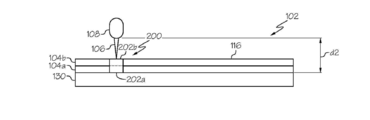
도 3 및 도 4를 참조하면, 하나의 예로서, 적층 제조 오퍼레이션 중에, 빌드 플랫폼(130)은 전자기 방사 소스(108)로부터 멀어지는 수직 거리(d1)에 위치될 수 있다. 금속 분말(116)의 제1 분말 층(104a)은, 도 3에 나타낸 것처럼 빌드 플랫폼(130) 상에 분포될 수 있다. 전자기 방사(106)는 도 4에 나타낸 것처럼 물품(200)의 제1 레이어(202a)를 형성하기 위해 제1 분말 층(104a)의 금속 분말(116)의 선택된 부분을 용융시킬 수 있다.Referring to Figures 3 and 4, as one example, during the laminate manufacturing operation, the
도 5 및 도 6을 참조하면, 따라서 빌드 플랫폼(130)은 전자기 방사 소스(108)로부터 수직 거리(d2)까지 수직으로 움직일 수 있다. 금속 분말(116)의 제2 분말 층(104b)은, 도 5에 나타낸 것처럼 빌드 플랫폼(130) 및/또는 적어도 물품(200)의 일부 위에 분포될 수 있다. 전자기 방사(106)는 물품(200)의 제2 레이어(202b)를 형성하기 위해 제2 분말 층(104b)의 금속 분말(116)의 선택된 부분을 용융시킬 수 있다.5 and 6, the
지시가 있지 않으면, 용어 "제1", "제2", 등은 여기서 단지 표시로서 사용되는 것이지, 이 용어들이 지칭하는 아이템들에 순서적인, 위치적인, 또는 계층적인 필요조건을 부과하려는 것은 아니다. 더욱이, 숫자의 아이템(예를 들어, "제2" 아이템)의 지칭은 낮은-숫자의 아이템(예를 들어, "제1" 아이템) 및/또는 더 높은 숫자의 아이템(예를 들어, "제3" 아이템)을 요구하거나 배제하는 것은 아니다.Unless otherwise indicated, the terms "first "," second ", etc. are used herein merely as an indication, and are not intended to impose an order, positional or hierarchical requirement on the items . Moreover, the designation of a numerical item (e.g., a "second" item) may include a low-number item (e.g., a "first" item) and / 3 "items).
각각의 연속적인(예를 들어, 적층의) 레이어(202)는 물품(200)을 형성하기 위해 응고된 균질의(homogeneous) 구성체(mass)를 형성하도록 이전의 레이어(202) 위에 형성된다. 이에 따라, 기술계에서의 당업자들은 도 6에서 제1 레이어(202a) 및 제2 레이어(202b)를 분리하는 파선은 오로지 적층 제조 프로세스의 본 발명에 따른 실시예를 묘사하기 위한 목적을 위함이고 물품(200)을 형성하는 레이어(202) 사이의 임의의 분리(예를 들어, 물리적 또는 구조적 분리)를 의미하는 것은 아니라는 것을 인식할 것이다.Each successive (e.g., stacked)
기술계에서의 당업자들은 빌드 플랫폼(130)이 전자기 방사 소스(108)로부터 멀어지면서 수직으로 움직이는 것을 인식할 것이고, 수직거리(d2) 및 수직거리(d1) 사이의 차는 각각의 분말 층(104)의 두께를, 따라서 각 레이어(202)의 두께를 또한 정의할 수 있다. 각 분말 층(104)의 두께(t1) 그리고, 따라서 각 레이어(202)의 두께는, 예를 들어 빌드 플랫폼(130) 및/또는 물품(200) 상의 분말 층(104)으로 금속 분말(116)의 디스펜싱(dispensing) 방법, 빌드 플랫폼(130) 및/또는 전자기 방사 소스(108)의 상대적인 움직임, 특정 타입의 전자기 방사(106), 전자기 방사(106)의 움직임, 프로세스 파라미터(112) 및 기타 등등의 다양한 다른 인자들에 의해 또한 정의될 수 있다.Those skilled in the art will appreciate that the
도 1 및 도 2를 참조하면, 장치(102)는 분말-격납부(powder-containment compartment)(138)를 더 포함할 수 있다. 분말-격납부(138)는 금속 분말(116)을 담을 수 있게 구성된다. 분말-격납부(138)는 분말-베드 용량(powder-bed volume)(104)의 적어도 일부분을 정의한다. 유사하게, 빌드 플랫폼(130)은 적어도 부분적으로 분말-베드 용량(140)의 범위를 정한다. 하나의 예로서, 금속 분말(116)은, 빌드 플랫폼(130) 위에 쌓이는 때에 분말-겹납부(138)에 의해 담겨진다. 빌드 플랫폼(130)은 분말-겹납부(108) 내에서 선형적으로 움직일 수 있다(예를 들어, 134 화살표 방향으로). 1 and 2, the
분말-겹납부(138) 내에서 선형적으로(예를 들어, 수직으로) 빌드 플랫폼(130)을 움직이는 것은 분말-베드 용량(140)을 변화시킨다. 따라서, 분말-베드 용량(140)은 빌드 플랫폼(130)의 포지션에 기반하여 가변적이다. 하나의 예로서, 빌드 플랫폼(130)이 전자기 방사 소스(108)로부터 멀리 움직임에 따라, 분말-베드 용량(140)은 증가하고, 이에 의해 추가적인 분말 층(104)을 형성하기 위한 추가적인 금속 분말(116)의 분포 및 물품(200)의 추가적인 레이어들(202)의 형성이 가능해 진다.Moving the
도 1을 참조하면, 장치(102)는 분말 디스펜서(142)를 더 포함할 수 있다. 분말 디스펜서(142)는, 분말 층(104)(예를 들어, 제1 분말 층(104a), 제2 분말 층(104b), 등등)(도 3 내지 도 6)을 형성하기 위해 연속적인 레이어들 형태로, 분말(116)을 분말-격납부(138) 속에, 빌드 플랫폼(130) 위에 및/또는 물품(200) 위에 쌓도록(deposit) 구성될 수 있다. 하나의 예로서, 분말 디스펜서(142)는 일정한 두께를 갖는 금속 층(104)으로서, 금속 분말(116)을 빌드 플랫폼(130) 및/ 또는 이전에 처리된 분말 층(104)(예를 들어, 물품(200)의 이전 레이어(202))에 쌓을 수 있다. 일반적으로, 분말 디스펜서(142)는 분말 소스로부터 금속 분말(116)을 수신하고 분말 소스로부터의 금속 분말(116)을 빌드 플랫폼(130)에 공급하도록 구성되는 임의의 기계장치, 디바이스 또는 시스템을 포함할 수 있다.Referring to FIG. 1, the
도 2와 함께 도 1을 참조하면, 장치(102)는 제어 유닛(144)을 더 포함할 수 있다. 제어 유닛(144)은 전자기 방사 소스(108), 전자기 방사 소스 구동 기계장치(118), 전자기 방사 조종 기계장치(120), 빌드 플랫폼 구동 기계장치(132) 및/또는 분말 디스펜서(142)를 제어하도록 구성되고 이들과 통신할 수 있다.Referring to Fig. 1 together with Fig. 2, the
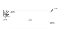
도 1과 함께 도 7을 참조하면, 물품(200)은 베이스 물질(예를 들어, 금속 분말(116))로부터 형성되는 응고된 균질의(homogeneous) 구성체(mass)를 포함한다. 물품(200)은 금속 분말(116)의 연속적인 분말 층들(104)(도 1)을 레이어 별로 조사(照射)함으로써 성장한다. 따라서, 본 발명에 따른 적층 제조 프로세스의 실시예들은 본질적으로 물품(200)을 형성하기 위해 베이스 물질(예를 들어, 금속 분말(116))의 용융 및 응고 프로세스로 정의될 수 있다.Referring to FIG. 7, in conjunction with FIG. 1,
일반적으로, 물품(200)은 복수의 연속적인 레이어들(202)에 의해 형성된다. 하나의 예로서, 그리고 도 7에 최적으로 도시되었듯이, 물품(200)은 응고된 균질의 물품(200)을 형성하기 위해, 제1 레이어(202a), 하나 이상의 내부 레이어들(202c)(예를 들어, 제1 레이어(202a)와 최상부(topmost) 레이어(202n) 사이에 배치된 제2 레이어(202b) 및 임의의 추가적인 레이어들(202)) 및 최상부(예를 들어, 최종의) 레이어(202n)를 포함할 수 있다. 각각의 연속적인(예를 들어, 부가되는) 레이어(202)는, 응고된 균질의 물품(200)을 형성하기 위해, 이전의 레이어(202)(예를 들어, 제2 레이어(202b)는 제1 레이어(202a) 위에 형성될 수 있고, 제3 레이어(202c)는 제2 레이어(202b) 위에 형성될 수 있다, 등등) 위에 형성될 수 있다. 물품(200)을 형성하기 위해 건설된 레이어들(202)의 전체 수는, 예를 들어 물품의 모양, 크기 및/또는 구조에 따라 제한 없이 변할 수 있다. 이에 따라, 기술계에서의 당업자들은 이에 따라, 기술계에서의 당업자들은 도 7에서 레이어들(202)을 분리하는 파선은 오로지 적층 제조 프로세스의 본 발명에 따른 실시예를 묘사하기 위한 목적을 위함이고 물품(200)을 형성하는 레이어(202) 사이의 임의의 분리(예를 들어, 물리적 또는 구조적 분리)를 의미하는 것은 아니라는 것을 인식할 것이다.Generally, the
도 1과 함께 도 7을 참조하면, 물품(200)은 위조방지 마크(anti-counterfeiting mark)(206)를 포함할 수 있다. 위조방지 마크(206)는 적층 제조 프로세스의 실시예에 의해 물품(200)의 창조 또는 형성 중에 물품(200) 내에 형성될 수 있다. 하나의 예로서, 그리고 도 7에 최적으로 도시되었듯이, 위조방지 마크(206)는 적어도 최상부 레이어(202n)의 일부에, 예를 들면, 물품(200)의 외부 표면(210) 근처(예를 들어, 임의의 장소 또는 부근)에 형성될 수 있다. 예를 들면, 위조방지 마크(206)는 외부 표면(210)에 형성되어 적어도 물품(200)의 두께를 통하여 부분적으로(예를 들어, 최상부 레이어(202n)) 펼쳐질 수 있다. 또 다른 예를 들면, 위조방지 마크(206)는 내부 레이어(202c)에 형성될 수 있는데, 이와 직접적으로 최상부 레이어(202n)가 선행하고, 적어도 부분 물품(200)의 두께를 통해 부분적으로 펼쳐질 수 있고 그리고 최상부 레이어(202n)는, 이를 통해 위조방지 마크(206)가 식별될 수 있는, 보호 레이어(예를 들어, 매우 얇은)일 수 있다. 어느 경우에서도, 물품(200)은 외부 표면(206) 및/또는 위조방지 마크(206)를 덮을 수 있는, 이를 통해 위조방지 마크(206)가 식별될 수 있는, 보호(그리고 예를 들어, 실질적으로 투명한) 코팅(미도시)을 포함할 수 있다. 이러한 예시에서, 물품(200)을 감정하기 위해 물품(200)(예를 들어, 물품(200)의 외부에서 보이는)의 외부(예를 들어, 외부 표면(210))를, 예를 들어 현미경 관찰과 같은 조사를 통해 위조방지 마크(206)는 식별될 수 있다.Referring to FIG. 7 together with FIG. 1, the
또 다른 예시로서(미도시), 위조방지 마크(206)는 물품(200)의 하나 이상의 내부 레이어들(202c)의 적어도 일부분에 형성될 수 있다. 예를 들어, 위조방지 마크(206)는 내부에 형성되어 물품(200)의 두께를 통해 적어도 부분적으로 펼쳐질 수 있다. 이러한 예에서, 위조방지 마크(206)는 물품(200)을 감정하기 위해 물품(200)의 내부(예를 들어, 물품(200)의 외부에서는 보이지 않는)를, 예를 들어 현미경 관찰과 같은 조사를 통해 위조방지 마크(206)는 식별될 수 있다.As another example (not shown), the
도 7과 함께 도 1을 참조하면, 물품(200)은 전체 마이크로스트럭처(204)를 포함하고, 각각의 레이어(202)는 레이어 마이크로스트럭처(210)를 포함하고 위조방지 마크(206)는 위조방지 마크 마이크로스트럭처(214)를 포함한다. 물품(200)의 마이크로스트럭처(304), 레이어 마이크로스트럭처(210) 및/또는 위조방지 마크 마이크로스트럭처(214)는 예를 들어, 프로세스 파라미터들(112)에 의해 정의되듯이, 각 분말 층(104)의 선택된 부분의 용융에 따른 금속 분말(116)의 용융 프로파일(profile), 각 분말 층(104)의 선택된 부분이 냉각되어 레이어(202)를 형성함에 따른 용융된 금속 분말(116)의 방향성 있는 응고 및/또는 다른 적합한 인자들에 의해 형성(예를 들어, 창조)될 수 있다.1, the
여기서 사용되듯이, "마이크로스트럭처(microstructure)"는 일반적으로 물질의 정교한 구조를 지칭하고, 그리고 때때로 금속 또는 금속 합금의 폴리싱(polishing) 또는 에칭(etching)과 같은 표면 준비 후에, 보통 (육안으로 보다는) 현미경을 통해 볼 수 있다.As used herein, "microstructure" refers generally to the sophisticated structure of a material, and sometimes after surface preparation, such as polishing or etching of a metal or metal alloy, ) Can be seen through a microscope.
따라서, 물품(200)의 마이크로스트럭처(204)는, 예를 들어, 현미경을 통한 관찰 및/또는 금속 조직학(metallography)에 의해 검사 되듯이, (예를 들어, 물품(200)을 형성하는 응고된 금속 분말(116)의) 물리적 구조(physical structure), 물리적 특징들(physical features), 결정 구조(grain structure) 및/또는 지향(orientation) 및/또는 물품(200)에서의 응용들(variations) 또는 변화들(changes)일 수 있다. 레이어 마이크로스트럭처(210)는, 예를 들어, 현미경을 통한 관찰 및/또는 금속 조직학에 의해 검사되듯이(예를 들어, 레이어(202)를 형성하는 응고된 금속 분말(116)의) 물리적 구조, 물리적 특징들, 결정 구조 및/또는 지향 및/또는 레이어(201)에서의 응용들 또는 변화들일 수 있다. 위조방지 마크 마이크로스트럭처(214)는, 예를 들어, 현미경을 통한 관찰 및/또는 금속 조직학에 의해 검사 되듯이, (예를 들어, 위조방지 마크(206)를 형성하는 응고된 금속 분말(116)의) 물리적 구조, 물리적 특징들, 결정 구조 및/또는 지향 및/또는 위조방지 마크(206)에서의 응용들 또는 변화들일 수 있다.The microstructures 204 of the
위조방지 마크(206)는 마이크로스트럭처에서의 응용들에 의해 형성되거나 정의될 수 있다. 하나의 예로서, 위조방지 마크(206)는 물품(200)의 적어도 일부분의 마이크로스트럭처(204)를 변화시킴으로써 형성될 수 있다. 또 다른 예로서, 위조방지 마크(206)는 물품(200)의 적어도 하나의 레이어(202)(예를 들어, 내부 레이어(202c) 또는 최상부 레이어(202n))의 적어도 일부분의 레이어 마이크로스트럭처(210)를 변화시킴으로써 형성될 수 있다.The
물품(200)의 마이크로스트럭처(204)(또는 물품(200)의 각 레이어(202)의 레이어 마이크로스트럭처(210))는 세팅 및/또는 다양한 프로세스 파라미터(112) 조종(manipulation)에 의해 제어될 수 있다. 물품(200)의 형성 중에 프로세스 파라미터(112)를 수정 및/또는 조종함으로써, 물품(200)은 균일한 또는 균질의 마이크로스트럭처(204)(예를 들어, 물품(200)의 각 레이어(202)는 동일한 레이어 마이크로스트럭처(212)를 포함한다) 또는 균일하지 않은 또는 비균질의 마이크로스트럭처(204)(예를 들어, 물품의(200)의 하나 이상의 레이어(202)는 상이한 레이어 마이크로스트럭처(212)를 포함한다)를 포함할 수 있다. 물품(200)의 형성 중에 프로세스 파라미터들(112)을 수정 및/또는 조종함으로써, 물품(200)의 적어도 하나의 레이어(202)의 적어도 일부분(예를 들어, 내부 레이어(202c) 또는 최상부 레이어(202n))는 레이어(202)의 레이어 마이크로스트럭처(212)(또는 물품(200)의 전체 마이크로스트럭처(204))와 상이한 위조방지 마크 마이크로스트럭처(214)를 포함할 수 있다.The microstructures 204 of the article 200 (or the
예를 들어, 프로세스 파라미터(112)는 금속 분말(116)의 용융 속도(melting speed)(164), 전자기 방사(106)의 파워 레벨(166)(예를 들어, 에너지 출력), 전자기 방사(106)의 방향(168), 금속 분말(116)의 용융 온도(170), 용융된 금속 분말(116)의 유지 온도(hold temperature)(172), 유지 시간(hold time)(174), 금속 분말(116)을 응고시키기 위한 냉각 시간(cool down time)(176), 전자기 방사 소스(108)의 스캔 속도(178)(예를 들어, 전자기 방사 소스(108)가 분말 층(194)에 대해 움직이는 속도) 및/또는 초점 오프셋 값(focal offset value)(182)(예를 들어, 최적의(optimal) 스팟 밀도(spot density)를 위한 초점 거리(focal distance)의 알려진 수렴(convergence)으로부터의 조정)을 포함할 수 있고, 그러나 이에 한정되는 것은 아니다.For example, the process parameters 112 may include the melting speed 164 of the
하나의 예시로서, 위조방지 마크(206) 및, 따라서 위조방지 마크 마이크로스트럭처(214)는 물품(200)의 최상부 레이어(202n)의 두께(t2)(도 7)의 일부분 또는 전체를 통해 펼쳐질(extend) 수 있다. 또 다른 예로서, 위조방지 마크(206) 및, 따라서 위조방지 마크 마이크로스트럭처(214)는 하나 이상의 내부 레이어(202c)의 두께의 일부분 또는 전체를 통해 펼쳐질(extend) 수 있다. 또 다른 예로서, 위조방지 마크(206) 및, 따라서 위조방지 마크 마이크로스트럭처(214)는 최상부 레이어(202n) 및 최상부 레이어(202n)와 직접 인접한 하나 이상의 내부 레이어(202c)의 두께의 일부분 또는 전체의 두께(t2)를 통해(예를 들어, 물품(202)의 두께를 관통하는 부분 또는 전체를 통해) 펼쳐질(extend) 수 있다.As one example, the
기술계의 당업자들은 임의의 레이어(202)의 두께(예를 들어, 최상부 레이어(202n)의 두께(t2))는 일치하는 금속 층(104)의 두께(예를 들어, 금속 층(104n)의 두께(t1))에 의해 정의될 수 있음을 인정할 것이다. 하나의 예로서, 위조방지 마크(206) 및, 따라서 위조방지 마크 마이크로스트럭처(214)는 적어도 하나의 레이어 두께(예를 들어, 바람직하게는 0.010 인치(0.254mm))에서 최대 물품(200)의 두께-관통까지 분포할 수 있다. 또 다른 예로서, 위조방지 마크(206) 및, 따라서 위조방지 마크 마이크로스트럭처(214)는 최소 하나의 레이어 두께 이하부터 최대 하나의 레이어 두께까지 분포할 수 있다.Those skilled in the art will appreciate that the thickness of any layer 202 (e.g., the thickness t2 of the
주어진 레이어(202) 및 위조방지 마크(206) 및, 더 나아가, 위조방지 마크 마이크로스트럭처(214)가 주어진 레이어(202)를 통해 분포하는 범위의 두께는 이러한 두께 분포들에 한정되지 않는다. 예를 들어, 주어진 레이어(202)의 두께는 일치하는 금속 층(104)의 두께, 적층 제조 프로세스를 위해 사용되는 특정의 적층 제조 장치(102)(예를 들어, 전자기 방사 소스(108) 및/또는 전자기 방사(106)의 타입) 및/또는 적층 제조 프로세스의 주어진 프로세스 파라미터(112)에 의해 제한될 수 있다. 따라서, 임의의 주어진 레이어(202)의 두께는 예시의 두께 분포에 비해 훨씬 얇거나 훨씬 두껍다.The thickness of the range over which a given
물품 프로세스 파라미터들(156)은 물품(200)이 전체 물품 마이크로스트럭처(204)(예를 들어, 레이어 마이크로스트럭처(212)의 조합에 의해 정의되는)를 포함하도록, 물품(200)의 모든 레이어들(202)(예를 들어, 최상부 레이어(202n)를 통한 제1 레이어(202a))을 형성하는데 이용될 수 있다. 물품 프로세스 파라미터들(156)은 각 레이어(202)와 동일하거나 하나 이상의 레이어들(202)에 대해 달라질 수 있다.The article process parameters 156 may be used to determine whether all of the
예를 들어, 물품 프로세스 파라미터들(156)은 프로세스 파라미터들(112)의 하나의 예시일 수 있으며, 각각의 연속적인 분말 층(104)의 금속 분말(116)의 용융 속도(melting speed)(164), 각각의 연속적인 분말 층(104)의 금속 분말(116)에 적용되는 전자기 방사(106)의 파워 레벨(power level)(166)(예를 들어, 에너지 출력), 각각의 연속적인 분말 층(104)의 금속 분말(116)에 적용되는 전자기 방사(106)의 방향(direction)(168), 각각의 연속적인 분말 층(104)의 금속 분말(116)의 용융 온도(melting temperature)(170), 각각의 연속적인 분말 층(104)의 용융된 금속 분말(116)의 유지 온도(hold temperature)(172), 각각의 연속적인 분말 층(104)의 용융된 금속 분말(116)의 유지 시간(hold time)(174), 각각의 연속적인 분말 층(104)의 금속 분말(116)을 응고시키기 위한 냉각 시간(cool down time)(176), 각각의 연속적인 분말 층(104)의 전자기 방사(106)의 스캔 속도(scanning speed)(178) 및/또는 초점 오프셋 값(focal offset value)(182)을 포함할 수 있으며, 그러나 이에 한정되는 것은 아니다.For example, the article process parameters 156 may be an example of the process parameters 112, and may include the melting speed 164 of the
위조방지 마크 프로세스 파라미터(162)는 하나 이상의 레이어들(202)의 적어도 일부가, 이러한 하나 이상의 레이어들(202)의 레이어 마이크로스트럭처(212)와 상이한 위조방지 마크 마이크로스트럭처(214)를 포함하도록, 물품(200)의 하나 이상의 레이어들(202)(예를 들어, 내부 레이어(202c), 최상부 레이어(202n) 또는 이들의 조합)에서 위조방지 마크(206)를 형성하는데 이용될 수 있다.The anti-tamper mark process parameter 162 may be configured to include at least some of the one or
예를 들어, 위조방지 마크 프로세스 파라미터(162)는 프로세스 파라미터(112)의 하나의 예시일 수 있고 그리고 하나 이상의 연속적인 분말 층(104)(예를 들어, 최상부 분말 층(104n), 이전의 분말 층 또는 이들의 조합)의 금속 분말(116)의 선택된 부분의 용융 속도(melting speed)(164), 하나 이상의 연속적인 분말 층(104)의 금속 분말(116)에 적용되는 전자기 방사(106)의 파워 레벨(power level)(166)(예를 들어, 에너지 출력), 하나 이상의 연속적인 분말 층(104)의 금속 분말(116)의 선택된 부분에 적용되는 전자기 방사(106)의 방향(direction)(168), 하나 이상의 연속적인 분말 층(104)의 금속 분말(116)의 선택된 부분의 용융 온도(melting temperature)(170), 하나 이상의 연속적인 분말 층(104)의 금속 분말(116)의 용융되고 선택된 부분의 유지 온도(hold temperature)(172), 하나 이상의 연속적인 분말 층(104)의 용융된 금속 분말(116)의 선택된 부분의 유지 시간(hold time)(174), 하나 이상의 연속적인 분말 층(104)의 금속 분말(116)의 선택된 부분을 응고시키기 위한 냉각 시간(cool down time)(176), 하나 이상의 연속적인 분말 층(104)의 선택된 부분의 전자기 방사(106)의 스캔 속도(scanning speed)(178) 및/또는 초점 오프셋 값(focal offset value)(182)을 포함할 수 있으나, 그러나 이에 한정되는 것은 아니다.For example, anti-tamper mark process parameters 162 can be an example of process parameters 112 and include one or more successive powder layers 104 (e.g., top powder layer 104n, The melting speed 164 of a selected portion of the metal powder 116 of the layer of powder 104 or the combination of the electromagnetic radiation 106 applied to the metal powder 116 of the at least one continuous powder layer 104, A power level 166 (e.g., energy output), a direction of electromagnetic radiation 106 applied to a selected portion of the metal powder 116 of one or more continuous powder layers 104 (e.g., The melting temperature 170 of a selected portion of the metal powder 116 of the at least one continuous powder layer 104 and the melting temperature 170 of the metal powder 116 of the at least one continuous powder layer 104 The hold temperature 172 of the selected portion, one or more continuous powders A hold time 174 of a selected portion of the molten metal powder 116 of the metal powder layer 104, a cooling time to solidify a selected portion of the metal powder 116 of the at least one continuous powder layer 104 a cool down time 176, a scanning speed 178 and / or a focal offset value 182 of the electromagnetic radiation 106 of a selected portion of the one or more continuous powder layers 104, But is not limited thereto.
따라서, 물품(200)의 마이크로스트럭처(204)는, 예를 들어 현미경으로 볼 수 있는 것과 대체로 유사한 결정 지향 및/또는 물리적 구조를 포함할 수 있다. 예를 들어, 일반적으로 물품(200)의 관통하는-두께를 통해 예를 들어, 현미경으로 볼 수 있는 물품(200)의 결정 지향(grain orientation) 및/또는 물리적 구조가 동일하도록, 레이어 마이크로스트럭처(212)는 물품(200)의 형성을 통해(예를 들어, 레이어(202) 다음 레이어(202) 식으로) 반복될 수 있다. 다음에 한정되는 것은 아니지만, 예를 들어 다음의 마크들, 모양(shape), 패턴(pattern), 직조 영역(textured area), 이미지(image), 텍스트(text), 수들(numbers) 및/또는 코드(code) 및 바람직하게는 육안, 현미경 또는 다른 감지 디바이스에 의해 볼 수 있는 것 중에서 하나와 같은 미리 정의된 표시(representation)를 이루기 위해, 위조방지 마크 마이크로스트럭처(214)는 상이한(different)(예를 들어, 변화가 있는) 결정 지향 및/또는 물리적 구조(예를 들어, 프로세스 파라미터(112)를 의도적으로 조종함으로써)를 포함할 수 있다.Thus, the microstructure 204 of the
도 8을 참조하면, 물품(200)은 탭(208)을 포함하도록 적층적으로 제조될 수 있다. 탭(208)은 선택된 분말 층(104)의 부분(예를 들어, 최상부 분말 층(104n), 하나 이상의 이전의 분말 층(104) 또는 이들의 조합)(도 1))을 선택적으로 용융 및 냉각시킴으로써 형성될 수 있다. 따라서, 탭(208)은 물품(200)의 하나 이상의 레이어들(202)(예를 들어, 제1 레이어(202a), 최상부 레이어(202n), 하나 이상의 내부 레이어들(202c) 또는 이들의 조합)의 확장일 수 있다. 하나의 예로서, 탭(208)은 하나의 레이어(202)의 두께(예를 들어, 최상부 레이어(202n)의 두께)와 동일하거나 이보다 두꺼운 두께를 포함할 수 있다.8, the
위조방지 마크(206)는 탭(208) 내에 형성될 수 있다. 탭(208)은 레이어 마이크로스트럭처(212)를 포함할 수 있고 위조방지 마크(206)는 탭(208)의 레이어 마이크로스트럭처(212)와 상이한 위조방지 마크 마이크로스트럭처(214)를 포함할 수 있다. 물품(200)의 인증이 수립되거나 확인되면 손상이나 물품(200)의 기능상 사용을 바꾸지 않고 탭(208)은 쉽게 제거될 수 있다.An
도 1과 함께 도 7 및 도 8을 참조하면, 위조방지 마크(206)는 물품(200)의 진정성(authenticity)을 확인할 수 있는 임의의 적절한 마킹을 포함할 수 있다. 예를 들어, 위조방지 마크(206)는 이미지(예를 들어, 로고(logo)), 심벌(symbol), 하나 이상의 알파벳 문자들의 스트링, 하나 이상의 숫자들의 스트링, 바코드, QR 코드, 이들의 조합 또는 예를 들어, 브랜딩 엘리먼트들(branding elements)을 포함하는 임의의 다른 표시 형식을 포함할 수 있는데, 이에 한정되는 것은 아니다.Referring to FIGS. 7 and 8 together with FIG. 1, the
위조방지 마크(206)(예를 들어, 위조방지 마크(206)가 형성되는 물품(200)의 외부 표면(210) 또는 내부)의 크기(예를 들어, 2차원 표면 영역)는 비교적 작은 크기부터(예를 들어, 밀리미터, 미크론 또는 이하 범위에서) 비교적 큰 크기까지(예를 들어, 센티미터, 인치 또는 이하 범위에서) 바람직하게 변할 수 있다. 위조방지 마크(206)의 크기(예를 들어, 작은 것부터 큰 것까지)는 물품(200)의 크기 및/또는 기능, 위조방지 마크(206)에 의해 표시되는 형태, 물품의 인증 등 기타 중에 위조방지 마크(206)를 식별하는데 사용되는 이미징 시스템(114)의 타입 및/또는 구성을 포함하는, 다만 이에 한정되는 것은 아닌, 다양한 인자들(factors)에 의존한다.The size (e.g., the two-dimensional surface area) of the anti-tamper mark 206 (e.g., the
위조방지 마크(206)가 물품(200)의 외부에 근접하여 형성되는 때에(예를 들어, 최상부 레이어(202n)의 외부 표면(210)에서), 위조방지 마크(206)가 위조방지 마크 마이크로스트럭처(214) 및 레이어(202)의 레이어 마이크로스트럭처(212)(또는 물품 마이크로스트럭처(204)) 간의 차이 또는 변화에 의해 형성되기 때문에, 위조방지 마크(206)는 물품(200)의 외부로부터 인간의 시야 또는 일반적인 확대(예를 들어, 25배 이하의 확대) 하에서는 보이지 않는다. 유사하게, 위조방지 마크(206)가 물품(200)의 내부에(예를 들어, 하나 이상의 내부 레이어들(202c)) 형성되는 때에, 위조방지 마크(206)는 물품(200)의 외부로부터 인간의 시야 또는 일반적인 확대 하에서는 보이지 않는다. 따라서, 위조방지 마크(206)를 보기 위해 그리고 진정한 것으로 물품(200)을 인증하기 위해 이미징 시스템(114)(도 1)이 사용될 수 있다.When the
이미징 시스템(114)은 여기서의 상관의 변화들을 식별하기 위해서 미시적인 레벨에서(예를 들어, 25배 이상의 확대) 레이어 마이크로스트럭처(212)(또는 물품 마이크로스트럭처(204)) 및 위조방지 마이크로스트럭처(214)를 관찰할 수 있는 임의의 이미지 또는 스캐닝 시스템을 포함할 수 있다. 하나의 예로서, 이미징 시스템(114)은 물품(200)의 외부에서 위조방지 마크(206)를 관찰할 수 있는(예를 들어, 레이어 마이크로스트럭처(212) 및 위조방지 마크 마이크로스트럭처(214) 사이의 이질성(inhomogeneity)) 이미지 또는 스캐닝 시스템을 포함할 수 있다. 또 다른 예로서, 이미징 시스템(114)은 물품(200)의 내부에서 위조방지 마크(206)를 볼 수 있는(예를 들어 레이어 마이크로스트럭처(212) 및 위조방지 마크 마이크로스트럭처(214) 사이의 이질성(inhomogeneity)) 이미지 또는 스캐닝 시스템을 포함할 수 있다. 일반적이고, 제한적이지 않은 예시로서, 이미징 시스템(114)는 임의의 적당한 현미경 시스템 또는 디바이스를 포함할 수 있다. 구체적이고, 제한적이지 않은 예시들로서, 이미징 시스템(114)은 광학 현미경 시스템(optical microscopy system), 전자 현미경 시스템(electron microscopy system), 스캐닝 프로브 현미경 시스템(scanning probe microscopy system), 자외선 현미경 시스템(ultraviolet microscopy system), 적외선 현미경 시스템(infrared microscopy system), 레이저 현미경 시스템(laser microscopy system), X-레이 현미경 시스템(x-ray microscopy system) 기타 등을 포함할 수 있는데, 이에 한정되는 것은 아니다.Imaging system 114 may include a layer microstructure 212 (or article microstructure 204) at a microscopic level (e.g., greater than 25 times magnification) to identify changes in correlation herein and an anti-fake microstructure 214, < / RTI > As an example, the imaging system 114 may include an anti-fake mark 206 (e.g., between layer microstructures 212 and anti-fake mark microstructures 214) (E.g., inhomogeneity of the image) or a scanning system. As another example, the imaging system 114 may be configured to display the
도 1을 참조하면, 여기에 묘사된 장치(102)의 실시예들은 여기에 개시된 적층 제조 프로세스의 실시예들을 구현하기 위한 컴퓨터 시스템(146) 및/또는 컴퓨터 프로그램 제품(152)(예를 들어, 소프트웨어-기반의 툴 또는 애플리케이션)을 포함할 수 있다. 제어 유닛(144)은 컴퓨터 시스템(146)과 통신할 수 있다. 컴퓨터 시스템(146) 및/또는 컴퓨터 프로그램 제품(152)는 물품(200)을 적층적으로 제조하기 위해 프로세스 데이터(154)를 이용할 수 있다.Referring to Figure 1, embodiments of the
컴퓨터 프로그램 제품(152)은 컴퓨터 시스템(146)에 의해 구현될 수 있다. 컴퓨터 시스템(146)은 하나 이상의 컴퓨터들(148)을 포함할 수 있다. 하나 이상의 컴퓨터(48)가 컴퓨터 시스템(146)에 제공되는 때에, 컴퓨터(148)는 통신 매체를 통해 서로 통신이 가능하다(예를 들어, 유선 및/또는 무선의 통신 연결들 또는 컴퓨터 네트워크를 사용하여).The
프로세스 데이터(154)는 적층 제조 프로세스에 의해 물품(200)을 형성하는데 이용되는, 임의의 프로세스 정보, 프로세스 제어들, 프로세스 입력들, 프로세스 인자들, 베이스 물질 특성들 및 기타 등을 포함할 수 있다. 프로세스 데이터(154)는 데이터베이스(150)에서 저장 및/또는 공유될 수 있다. 예를 들어, 데이터베이스(150)는 프로세스 데이터(154)를 위한 저장소로서 기능할 수 있다. 컴퓨터 시스템(146)은 프로세스 데이터(154)에 접근하기 위해 데이터베이스(150)과 통신할 수 있다.
일반적이고, 제한적이지 않은 예시로서, 프로세스 데이터(154)는 프로세스 파라미터들(112)(예를 들어, 물품 프로세스 파라미터들(156) 및/또는 위조방지 마크 프로세스 파라미터들(162)), 물품(200)의 3차원 모델(158) 및/또는 위조방지 마크(206)의 위조방지 이미지(160)을 포함할 수 있다.
3차원 모델(158)은 물품(200)의 3D CAD 이미지(예를 들어, 가상의 표시)일 수 있다. 하나의 구체적이고, 제한적이지 않은 예시로서, 3차원 모델(158)은 스테레오리소그래피(STereoLithography, STL) 파일 포맷을 포함할 수 있다. 3차원 모델(158)은 물품(200)을 형성하기 위해 컴퓨터 시스템(146) 및/또는 제어 유닛(144)에 의해 사용될 수 있다. 하나의 예시로서, 3차원 모델(158)은 스테레오그래피 CAD 소프트웨어 애플리케이션에 의해 생성될 수 있다. 또 다른 예시로서, 3차원 모델(158)은 컴퓨터 프로그램 제품(152)에 의해 생성될 수 있다.The three-
전자기 방사(106)를 이용하는 선택적 조사(예들 들어, 용융)를 하기 위해 각 분말 층(104)의 금속 분말(116)의 선택된 부분에 관한 명령들을 제어 유닛(144)에 제공하는 컴퓨터 프로그램에 의해 3차원 모델(158)이 처리될 수 있다. 하나의 예시로서, 3차원 모델(158)은 물품(200)의 각 레이어(202)를 나타내는 복수의 단면들로 슬라이싱 될 수 있다.By a computer program that provides the
위조방지 이미지(160)는 위조방지 마크(206)의 3D CAD 이미지(예를 들어, 가상 표시)일 수 있다. 구체적이고, 제한적이지 않은 예시로서, 위조방지 이미지(160)는 스테레오리소그래피(STL) 파일 포맷을 포함할 수 있다. 물품(200)의 하나 이상의 레이어들(202)에서 위조방지 마크(206)를 형성하기 위해, 위조방지 이미지(160)는 컴퓨터 시스템(146) 및/또는 제어 유닛(144)에 의해 사용될 수 있다. 하나의 예시로서, 위조방지 이미지(160)는 스테레오리소그래피 CAD 소프트웨어 애플리케이션에 의해 생성될 수 있다. 또 다른 예시로서, 위조방지 이미지(160)는 컴퓨터 프로그램 제품(152)에 의해 생성될 수 있다.The anti-counterfeit image 160 may be a 3D CAD image (e.g., a virtual display) of the
전자기 방사(106)를 이용하는 선택적 조사(예들 들어, 용융)를 하기 위해 각 분말 층(104)의 금속 분말(116)의 선택된 부분에 관한 명령들을 제어 유닛(144)에 제공하는 컴퓨터 프로그램에 의해 위조방지 이미지(160)는 처리될 수 있다.(For example, fusing) by a computer program that provides the
도 1에서 적층 제조 환경(100)의 묘사된 실시예는, 다른 실시예들이 구현될 수 있는 방법에 물리적 또는 구조적 제한들을 제공하기 위해 의도된 것은 아니다. 다른 구성 요소들이 추가적으로 및/또는 묘사된 기존 것을 대체하여 사용될 수 있다. 몇몇 구성 요소들은 몇몇 예시들에서 불필요할 수 있다. 또한, 블록들은 일정 기능상의 구성 요소들을 묘사하기 위해 제공된다. 다른 실시예들에서 구현되는 경우에, 하나 이상의 이러한 블록들은 조합 및/또는 다른 블록들로 분할될 수 있다.The depicted embodiment of the laminate manufacturing environment 100 in FIG. 1 is not intended to provide physical or structural limitations to the manner in which other embodiments may be implemented. Other components may be used in place of the existing ones additionally and / or described. Some components may be unnecessary in some instances. Blocks are also provided to describe certain functional components. In other embodiments, one or more of these blocks may be combined and / or divided into other blocks.
도 9a 및 9b와 함께 도 1을 참조하면, 일반적으로 300번으로 지정된, 위조방지 마크를 이용하여 3차원 물품을 제조하기 위한 본 발명에 따른 하나의 실시예는, 302 블록에서 나타낸 것처럼, 물품(200)을 나타내는 3차원 모델(158)을 생성하는 단계로 시작된다. 310 블록에 나타낸 것처럼, 본 방법(300)은 위조방지 마크(206)의 표시를 생성하는 단계를 더 포함할 수 있다. 하나의 예시로서, 위조방지 마크(206)의 표시는 위조방지 이미지(160)를 포함할 수 있다. Referring to Figure 1 with Figures 9a and 9b, one embodiment in accordance with the present invention for producing a three-dimensional article using an anti-counterfeit mark, generally designated as 300,
342 블록에 나타낸 것처럼, 본 방법(300)은 3차원 모델(158)이 물품(200) 및 위조방지 마크(206)를 모두 표시하도록(예를 들어, 물품(200)의 표시 내에 집적 또는 포함되는 위조방지 이미지(160)의 표시를 갖는 모델), 위조방지 마크(206)와 3차원 모델(1588)의 표시를(예를 들어, 위조방지 이미지(160)) 예를 들어, 컴퓨터 프로그램 제품(152)을 이용하여 프로세싱 또는 결합하는 단계를 더 포함할 수 있다.As shown in
304 블록에 나타낸 것처럼, 본 방법(300)은, 304 블록에 나타낸 3차원 모델(158)의 단면 슬라이스들(180)을 생성하는 단계를 더 포함할 수 있다. 따라서, 하나 이상의 레이어들(202)에 해당하는 하나 이상의 단면 슬라이스들(180)은 위조방지 마크(206)(예를 들어, 위조방지 이미지)의 표시의 적어도 일부분을 포함할 수 있다. 예를 들어, 단면 슬라이스(180)는 적어도 하나의 레이어(202) 및 위조방지 마크(206)의 적어도 일부분을 표시할 수 있다.As shown in
344 블록에 나타낸 것처럼, 본 방법(300)은 적층 제조 장치(102)에서(예를 들어, 컴퓨터 시스템(146)으로부터 제어 유닛(144)까지) 3차원 모델(158)에 위조방지 마크(206)의 표시를(예를 들어, 위조방지 이미지(160)) 제공하는 단계를 더 포함할 수 있다. 예를 들어, 하나 이상의 레이어들(202)에 해당하거나 이들을 표시하는 복수의 단면 슬라이스들(180) 및 위조방지 마크(206)는 적층 제조 장치(102)에 제공될 수 있다.As shown in
306 블록에 나타낸 것처럼, 본 방법(300)은 물품(200)의 물품 마이크로스트럭처(204)(또는 하나 이상의 레이어(202)의 레이어 마이크로스트럭처(212))를 확정하기 위해, 적층 제조 프로세스에 대한 프로세스 파라미터들(112)(예를 들어, 물품 프로세스 파라미터들(156))을 생성하는 단계를 더 포함할 수 있다.As shown in
308 블록에 나타낸 것처럼, 본 방법(300)은 프로세스 파라미터들(112)(예를 들어, 하나 이상의 물품 프로세스 파라미터들(156))을 적층 제조 장치(102)에(예를 들어, 컴퓨터 시스템(146)으로부터 제어 유닛(144)까지) 제공하는 단계를 더 포함할 수 있다.As shown in block 308, the
312 블록에 나타낸 것처럼, 본 방법(300)은 적층 제조 프로세스가 위조방지 마크(206)의 위조방지 마크 마이크로스트럭처(214)를 확정하도록 하기 위해, 프로세스 파라미터들(112)을(예를 들어, 위조방지 마크 프로세스 파라미터들(162)) 생성하는 단계를 더 포함할 수 있다.As shown in
314 블록에 나타낸 것처럼, 본 방법(300)은 적층 제조 장치(102)로(예를 들어, 컴퓨터 시스템(146)으로부터 제어 유닛(144)까지) 변화된 또는 조종된 프로세스 파라미터들(112)을(예를 들어, 위조방지 마크 프로세스 파라미터들(162)) 제공하는 단계를 더 포함할 수 있다.As shown in
316 블록에 나타낸 것처럼, 본 방법(300)은, 전자기 방사(106)를 이용하여 금속 분말(116)의 선택된 부분의 스캐닝에 의한 적층 제조 프로세스에 의해 금속 분말(116)로부터 연속적으로 물품(200)을 설립하는 단계를 더 포함할 수 있다.As shown in
318 블록에 나타낸 것처럼, 본 방법(300)은 적층 제조 프로세스 중에(예를 들어, 현장에서) 물품(200)에서의 위조방지 마크(206)를 형성하는 단계를 더 포함할 수 있다.As shown in block 318, the
여기서 사용되듯이, "스캐닝(scanning)"은 일반적으로 전자기 방사(106)로 금속 분말(116)(예를 들어, 분말 층(104))의 선택된 부분을 조사하거나 다르게는 금속 분말(116)을 전자기 방사(106) 하에 있도록 하는 것을 지칭한다. 물품(200)의 각 레이어(202)를 형성하기 위해 전자기 방사(106)에 의해 스캔되는 금속 분말(116)의 선택된 부분은, 3차원 모델(158)의 단면 슬라이스들(180)에 따르면 물품(200)의 단면과 일치할 수 있다. 위조방지 마크(206)를 형성하기 위해 전자기 방사(106)에 의해 스캔되는 금속 분말(116)의 선택된 부분은, 3차원 모델(158)의 단면 슬라이스들(180)에 따르면 물품(200)의 단면의 일부와 일치할 수 있다.As used herein, "scanning" generally refers to irradiating a selected portion of metal powder 116 (e.g., powder layer 104) with
320 블록에 나타낸 것처럼, 물품(200)을 만들어 내는 단계(316 블록)는 분말 층(104)을 빌드 플랫폼(130) 위에 쌓는(deposit) 단계를 포함할 수 있다.As shown in
322 블록에 나타낸 것처럼, 물품(200)을 만들어 내는 단계(316 블록)는 전자기 방사(106)를 이용하여 분말 층(104)의 선택된 부분을 용융시키는 단계를 더 포함할 수 있다. As shown in
324 블록에 나타낸 것처럼, 물품(200)을 만들어 내는 단계는(316 블록) 차후의 분말 층들(104)을 각각의 이전 분말 층(104) 위에 쌓는(deposit) 단계를 더 포함할 수 있다.As shown in
326 블록에 나타낸 것처럼, 물품(200)을 만들어 내는 단계(316 블록)는 전자기 방사(106)를 이용하여 차후의 각 분말 층(104)의 선택된 부분을 용융시키는 단계를 더 포함할 수 있다.As shown in
328 블록에 나타낸 것처럼, 물품(200)을 만들어 내는 단계는(316 블록) 위조방지 마크(206)를 포함하는 물품(200)을 형성하기 위해 분말 층(104)의 선택된 부분과 차후의 각 분말 층(104)의 선택된 부분을 응고시키는(예를 들어, 냉각(cooling) 또는 경화(curing)) 단계를 더 포함할 수 있다.As shown in
하나의 실시예로서, 물품(200)을 만들어 내는 단계(316 블록)는 제1 분말 층(104a)을 빌드 플랫폼(130) 위로 쌓는(deposit) 단계를 포함할 수 있다. 제1 분말 층(104a)의 금속 분말(116)의 선택된 부분(예를 들어, 제1 레이어(202a)를 나타내는 단면 슬라이스(180)에 해당하는)은, 제1 레이어(202)를 형성하기 위해 전자기 방사(106)를 이용하여 용융될 수 있다. 제2 분말 층(104b)은 제1 레이어(202a) 및 제1 분말 층(104a) 위에 쌓일 수 있다. 제2 분말 층의 금속 분말(116)의 선택된 부분(예를 들어, 제2 레이어(202b)를 나타내는 단면 슬라이스(180)에 해당하는)은, 제2 레이어(202b)를 형성하기 위해 전자기 방사를 이용하여 용융될 수 있다. 예를 들어, 3차원 모델(158)에 따라 최종 단만 슬라이스(180)에 이르기까지, 임의의 수의 추가적인 내부 분말 층(104)은 이전의 분말 층들(104) 위에 즉시로 쌓일 수 있다. 최상부 분말 층(104n)(예를 들어, 최상부 레이어(202n)를 나타내는 단면 슬라이스(180)에 해당하는)는 이전의 내부 레이어(202c) 및 분말 층(104) 위에 즉시로 쌓일(deposit) 수 있다. 최상부 분말 층(104n)의 금속 분말(116)의 선택된 부분(예를 들어, 최상부 레이어(202n)를 나타내는 단면 슬라이스(180)에 해당하는)은, 최상부 레이어(202n)를 형성하기 위해 전자기 방사(106)을 이용하여 용융될 수 있다. 제1 분말 층(104a), 제2 분말 층(104b), 임의의 추가적인 내부 분말 층(104) 및 최상부 분말 층(104n)의 금속 분물(116)의 선택된 부분은, 제1 레이어(202a), 제2 레이어(202b), 임의의 추가적인 내부 레이어들(202c) 및 최상부 레이어(202n)가 서로 결합하도록 응고될 수 있다.In one embodiment, creating the article 200 (Block 316) may include depositing the
330 블록에 나타낸 것처럼, 위조방지 마크(206)을 형성하는 단계(318 블록)는, 전자기 방사(106)를 이용하여 차후의 분말 층들(104) 중에서 적어도 하나의 분말 층(104)의 선택된 부분을 용융시키는 단계를 포함할 수 있다.As shown in
332 블록에 나타낸 것처럼, 위조방지 마크(206)를 형성하는 단계(318 블록)는, 물품(200)에서 위조방지 마크(206)을 형성하기 위해 차후의 분말 층들(104) 중에서 적어도 하나의 분말 층(104)의 선택된 부분을 응고시키는 단계를 더 포함할 수 있다.As shown in
하나의 실시예로서, 위조방지 마크(206)을 형성하는 단계(318 블록)는, 물품(200)의 최상부 레이어(202n)에 위조방지 마크(206)를 형성하기 위해, 최상부 분말 층(104n)의 금속 분말(116)의 선택된 부분(예를 들어, 위조방지 이미지(160)를 갖는 최상부 레이어(202n)를 나타내는 단면 슬라이스(180)에 해당하는)을 용융시키는 단계를 포함할 수 있다. 또 다른 실시예로서, 위조방지 마크(206)를 형성하는 단계(318 블록)는, 물품(200)의 적어도 하나의 내부 레이어(202c)에 위조방지 마크(206)를 형성하기 위해, 적어도 하나의 내부 분말 층(104)의 금속 분말(116)의 선택된 부분(예를 들어, 위조방지 이미지(160)를 갖는 적어도 하나의 내부 레이어(202c)를 나타내는 단면 슬라이스(180)에 해당하는)을 용융시키는 단계를 포함할 수 있다.In one embodiment, the step of forming anti-counterfeit mark 206 (block 318) may include forming a top
기술계에서 당업자들은 물품(200)을 만들어 내는 단계(316 블록) 및 위조방지 마크(206)를 형성하는 단계(318 블록)가 실질적으로 동시에 일어날 수 있음을 인식할 것이다. 예를 들어, 적어도 하나의 레이어(202)(예를 들어, 적어도 하나의 내부 레이어(202c), 최상부 레이어(202n) 또는 이들의 조합)를 형성하기 위해 차후의 분말 층들(104) 중에서 적어도 하나의 분말 층(104)의 선택된 부분들과 적어도 하나의 레이어(202)에서의 위조방지 마크(206)를 용융 및 응고시키는 단계들은, 해당하는 레이어(202)에 대한 적층 제조 프로세스 중에 동시에 일어날 수 있다.Those skilled in the art will appreciate that steps (316 block) for creating
334 블록에 나타낸 것처럼, 본 방법(300)은 물품(200)의 물품 마이크로스트럭처(204)(또는 각 레이어(202)의 레이어 마이크로스트럭처(212))를 확정하는 단계를 더 포함할 수 있다.As shown in
336 블록에 나타낸 것처럼, 본 방법(300)은 위조방지 마크(206)의 위조방지 마크 마이크로스트럭처(214)를 수립하는 단계를 더 포함할 수 있다. 위조방지 마크 마이크로스트럭처(214)는 물품 마이크로스트럭처(204)와 상이하거나 이의 변형일 수 있다(또는 하나 이상의 레이어들(202)의 레이어 마이크로스트럭처(212)).As shown in block 336, the
338 블록에 나타낸 것처럼, 물품(200)의 물품 마이크로스트럭처(204)(또는 각 레이어(202)의 레이어 마이크로스트럭처(212))를 확정하는 단계(334 블록)는, 미리 결정된 물품 마이크로스트럭처(204)(또는 미리 결정된 레이어 마이크로스트럭처(212)을 갖는 각각의 레이어(212))를 갖는 물품(200)을 생성 또는 형성하기 위해 적층 제조 프로세스의 하나 이상의 프로세스 파라미터들(112)(예를 들어, 물품 프로세스 파라미터들(156))를 세팅하는 단계를 포함할 수 있다.(Step 334) of determining the article microstructures 204 (or the layer microstructures 212 of each layer 202) of the
340 블록에 나타낸 것처럼, 위조방지 마크(206)의 위조방지 마크 마이크로스트럭처(214)를 확정하는 단계는, 미리 결정된 위조방지 마크 마이크로스트럭처(214)를 갖는 적어도 하나의 레이어(202)에서 위조방지 마크(206)을 생성 또는 형성하기 위해, 하나 이상의 프로세스 파라미터들을(112) 조종하는(manipulating)(예를 들어, 위조방지 프로세스 파라미터들(162)을 세팅) 단계를 포함할 수 있다.The step of establishing the anti-fake mark microstructures 214 of the
346 블록에 나타낸 것처럼, 본 방법(300)은, 적층 제조 프로세스 중에 물품(200)이 적어도 하나의 레이어(202)에서 위조방지 마크(206)를 포함하는가를 결정하는 단계를 더 포함할 수 있다.As shown in
348 블록에 나타낸 것처럼, 물품(200)이 위조방지 마크(206)를 포함하는가를 결정하는 단계(346 블록)는, 예를 들어 이미징 시스템(114)을 이용하여 미시적인 레벨에서 물품(200)을 검사하고 조사하는 단계를 포함할 수 있다. 하나의 예시로서, 물품(200)의 적어도 하나의 레이어(202) 및 상기 레이어(202)에서의 위조방지 마크(206)의 형성 후에, 위조방지 마크(206)가 해당 레이어(202)에 알맞게 형성되었는지를 확인하기 위해 시각적으로 물품(200)(예를 들어 형성된 레이어(202))을 검사하는데 이미징 시스템(114)이 사용될 수 있다. 또 다른 예시로서, 물품(200)(예를 들어, 최상부 레이어(202n)의 형성 후에) 및 적어도 하나의 레이어(202)(예를 들어, 하나 이상의 내부 레이어(202c), 최상부 레이어(202n) 또는 이들의 결합)에서의 위조방지 마크(206)의 형성 후에, 위조방지 마크(206)가 알맞게 형성되었는지를 확인하기 위해 시각적으로 물품(200)을 검사하는데 이미징 시스템(114)이 사용될 수 있다.As shown in
예를 들어, 이미징 시스템(114)를 이용하는 물품(200)의 검사는, 위조방지 마이크로스트럭처(214) 및 물품 마이크로스트럭처(204)(또는 임의의 레이어 마이크로스트럭처(212)에서의 변화들(variations)를 감지할 수 있다.For example, inspection of an
위조방지 마크 마이크로스트럭처(214)는, 물품 마이크로스트럭처(204)(또는 적어도 하나의 레이어(202)에서의 레이어 마이크로스트럭처(212))와 비교하여 미시적으로 감지될 수 있는 변화를 포함할 수 있는데, 이는 물품(200)을 인증하는데 사용될 수 있다. 하나의 예시로서, 위조방지 마크(206)는 물품(200)을 인증하기 위한 적어도 하나의 브랜딩 엘리먼트(예를 들어, 위조방지 이미지(160)에 의해 정의되는)를 포함할 수 있다.Anti-tampering mark microstructures 214 may include changes that can be microscopically sensed as compared to article microstructures 204 (or layer microstructures 212 in at least one layer 202) This can be used to authenticate the
수정(modifications), 추가(additions), 또는 누락(omissions)이 본 발명의 범위를 벗어나지 않고 본 방법(300)에 만들어질 수 있다. 본 방법(300)은 더 많거나, 적거나 또는 다른 단계들을 포함할 수 있다. 추가적으로, 단계들은 임의의 적합한 순서로 수행될 수 있다.Modifications, additions, or omissions may be made to the
도 10은 데이터 처리 시스템(600)의 하나의 실시예를 묘사한다. 데이터 처리 시스템(600)은 컴퓨터 시스템(146)(도 1)의 컴퓨터(148)에 의해 제공되는 기능들을 수행하는데 사용되는 데이터 처리 시스템의 예시일 수 있다. 데이터 처리 시스템(600)은 프로세서 유닛(604), 메모리(606), 영구 저장소(608), 통신 유닛(610), 입력/출력("I/O") 유닛(612), 및 디스플레이(614) 간의 통신을 제공하는 통신 버스(602)를 포함할 수 있다.FIG. 10 depicts one embodiment of a
통신 버스(602)는 시스템 버스 또는 입력/출력 버스와 같은 하나 이상의 버스들을 포함할 수 있다. 통신 버스(602)는 다른 구성 요소들 또는 버스 시스템에 연결된 디바이스들 사이의 데이터 전송을 제공하는 임의의 적합한 타입의 구조를 사용하여 구현될 수 있다.
프로세서 유닛(604)은, 메모리(606)에 로드될 수 있는 소프트웨어에 관한 명령들을 수행하는 역할을 할 수 있다. 프로세서 유닛(604)은, 특정의 실시예에 따라 하나 이상의 프로세서들 또는 멀티-프로세서 코어일 수 있다. 하나의 예시로서, 프로세서 유닛(604)은 하나의 칩에서 메인 프로세서에 제2의 프로세서들이 제공되는 하나 이상의 이기종 프로세서 시스템들을 이용하여 구현될 수 있다. 또 다른 예시로서, 프로세서 유닛(604)는 같은 타입의 복수의 프로세서들을 포함하는 대칭의 멀티-프로세서 시스템일 수 있다.The processor unit 604 may be responsible for executing software-related instructions that may be loaded into the
메모리(606) 및 영구 저장소(608)는 스토리지 디바이스들(616)의 예시들일 수 있다. 스토리지 디바이스(616)는 데이터, 함수 형태에서의 프로그램 코드, 및/또는 임시적인 베이시스(temporary basis) 및/또는 영구적인 베이시스(permanent basis)에서의 다른 적합한 정보를 포함하는 정보를 저장할 수 있는 임의의 수의 하드웨어일 수 있으나, 이에 한정되는 것은 아니다. 예를 들어, 메모리(606)는 등속 호출 기억장치(RAM) 또는 임의의 다른 적합한 휘발성 또는 비휘발성의 스토리지 디바이스일 수 있다.
영구 저장소(608)는, 특정의 실시예에 따라 다양한 형태를 띨 수 있다. 영구 저장소(608)는 하나 이상의 구성 요소들 또는 디바이스들을 포함할 수 있다. 예를 들어, 영구 저장소(608)는 하드 드라이브, 플래시 메모리, 재기록이 가능한 광학 디스크, 재기록이 가능한 마그네틱 테입, 또는 이들의 조합일 수 있다. 영구 저장소(608)에 의해 사용되는 미디어는 떼어낼 수 있다. 예를 들어, 떼어낼 수 있는 하드 드라이가 영구 저장소(608)로서 사용될 수 있다.The
통신 유닛(610)은 통신을 위해 다른 데이터 처리 시스템들 또는 디바이스들을 제공할 수 있다. 예를 들어, 통신 유닛(610)은 네트워크 인터페이스 카드를 포함할 수 있다. 또 다른 예로서, 통신 유닛(610)은 모뎀 또는 네트워크 어댑터와 같은 데이터의 전송 및 수신에 사용되는 하나 이상의 디바이스들을 포함할 수 있다. 통신 유닛(610)은, 유선 및/또는 무선 통신 링크들의 이용을 통해 통신을 제공할 수 있다.
입력/출력 유닛(612)은 데이터 처리 시스템(600)에 연결된 다른 디바이스들과 데이터의 입력 및 출력을 가능하게 한다. 예를 들어, 입력/출력 유닛(612)은 키보드, 마우스, 및/또는 다른 적합한 입력 디바이스에 대한 연결을 제공할 수 있다. 더 나아가, 입력/출력 유닛(612)은 프린터 및/또는 디스플레이(614)로 출력을 전송할 수 있다. 디스플레이(614)는 정보를 디스플레이하는 기계장치를 제공할 수 있다.The input /
운영 체재, 애플리케이션들, 및/또는 프로그램들을 위한 명령들은 스토리지 디바이스(616)에 위치할 수 있다. 예를 들어, 명령들은 영구 저장소(608)에서 함수 형태로 있다. 명령들은 프로세서 유닛(604)에 의한 실행을 위해 메모리(606)에 로드될 수 있다. 다른 실시예들의 프로세스들은, 메모리(606)와 같은 메모리에 위치할 수 있는, 컴퓨터로 구현된 명령들을 사용하는 프로세서 유닛(604)에 의해 수행될 수 있다.The instructions for the operating system, applications, and / or programs may be located in the
상기 명령들은, 프로세서 유닛(604)에서의 프로세서에 의해 판독되고 수행될 수 있는, 프로그램 코드, 컴퓨터 사용 프로그램 코드, 또는 컴퓨터 판독 가능한 프로그램 코드로 불릴 수 있다. 다른 실시예들에서, 프로그램 코드는, 메모리(606) 또는 영구 저장소(608)과 같은 다른 물리적인 또는 컴퓨터로 판독 가능한 스토리지 미디어에 구현될 수 있다.The instructions may be referred to as program code, computer-usable program code, or computer-readable program code, which may be read and executed by a processor at the processor unit 604. [ In other embodiments, the program code may be embodied in other physical or computer readable storage media, such as
프로그램 코드(618)는 선택적으로 제거가 가능한 컴퓨터 판독 가능한 미디어(620)에서 함수 형태로 위치할 수 있고 그리고 프로세서 유닛(604)에 의한 실행을 위해 데이터 처리 시스템(600)에 로드되거나 전송될 수 있다. 프로그램 코드(618) 및 컴퓨터 판독 가능한 미디어(620)는 컴퓨터 프로그램 제품(152)를 형성할 수 있다. 하나의 예시로서, 컴퓨터 판독 가능한 미디어(620)는 컴퓨터 판독 가능한 미디어(624) 또는 컴퓨터 판독 가능한 신호 미디어(626)일 수 있다.The
컴퓨터 판독 가능한 스토리지 미디어(624)는, 영구 저장소(608)의 부분인 하드 드라이브와 같은 스토리지 디바이스로 전송하기 위한 영구 저장소(608)의 부분인 드라이브 또는 다른 디바이스에 삽입되거나 위치하는 광학 또는 마그네틱 디스크를 포함할 수 있는데, 이에 한정되는 것은 아니다. 컴퓨터 판독 가능한 스토리지 미디어(624)는 또한 데이터 처리 시스템(600)에 연결된 하드 드라이브, 썸 드라이브(thumb drive), 또는 플래시 메모리와 같은, 영구 저장소 형태를 띌 수 있다. 몇몇 경우들에서, 컴퓨터 판독 가능한 스토리지 미디어(624)는 데이터 처리 시스템(600)에서 떼어낼 수 있는 것이 아닐 수 있다.Computer
선택적으로, 프로그램 코드(618)는 컴퓨터 판독 가능한 신호 미디어(signal media)(626)을 이용하여 데이터 처리 시스템(600)으로 전송될 수 있다. 예를 들어, 컴퓨터 판독 가능한 신호 미디어는, 프로그램 코드(618)를 함유하는 전파되는 데이터 신호(data signal)일 수 있다. 컴퓨터 판독 가능한 신호 미디어(626)는 전자기 신호, 광학 신호, 및/또는 임의의 다른 적합한 타입의 신호를 포함할 수 있는데, 이에 한정되는 것은 아니다. 이러한 신호들은 무선 통신 링크들, 유선, 광섬유 케이블, 동축 케이블, 및/또는 임의의 다른 적합한 타입의 통신 링크와 같은 통신 링크들을 통해 전송될 수 있다.Optionally,
하나의 예시적인 실시예에서, 프로그램 코드(618)는, 다른 디바이스 또는 데이터 처리 장치로부터 데이터 처리 시스템(600) 내에서의 사용을 위한 컴퓨터 판독 가능한 신호 미디어(626)을 통해 영구적인 저장소(608)로 (예를 들어, 네트워크를 통해) 내려 받을 수 있다. 예를 들어 서버 데이터 처리 시스템에 있는 컴퓨터 판독 가능한 스토리지 미디어에 저장된 프로그램 코드는, 네트워크를 통해 서버에서 데이터 처리 시스템(600)으로 내려 받을 수 있다. 프로그램 코드(618)를 제공하는 데이터 처리 시스템은 서버 컴퓨터, 클라이언트 컴퓨터, 또는 프로그램 코드(618)의 저장 및 전송이 가능한 다른 디바이스일 수 있다.In one exemplary embodiment, the
도 1에서의 데이터 처리 시스템(600)의 도시된 실시예는, 다른 실시예들이 구현될 수 있는 방법에 대한 물리적 또는 구조적인 제한을 제공하려고 의도된 것은 아니다. 도시된 실시예들에 추가 및/또는 이들을 대체하는 그 밖의 구성 요소들이 사용될 수 있다. 몇몇 구성 요소들은 몇몇 예시적인 실시예들에서는 불필요할 수 있다. 또한, 몇몇 기능적인 구성 요소들을 묘사하기 위해 블록들을 나타내었다. 하나 이상의 이러한 블록들은, 다른 예시적인 실시예들을 구현하는 경우에, 조합 및/또는 다른 블록들로 분리될 수 있다.The illustrated embodiment of the
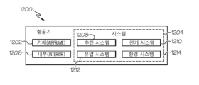
본 발명의 예시들은, 도 11에 나타낸 것처럼 항공기 제작 및 서비스 방법(1100) 및 도 12에 나타낸 것과 같은 항공기(1200)의 여건에서 묘사될 수 있다. 생산 전 단계 중에, 묘사된 방법(1100)은, 1102 블록에 나타낸 것처럼, 항공기(1200)의 사양 및 설계 그리고 1104 블록에 나타낸 것처럼, 자재 조달을 포함한다. 생산 중에, 1106 블록에 나타낸 것처럼, 구성요소 및 서브어셈블리 제조, 그리고 1108 블록에 나타낸 것처럼, 항공기(1200)의 시스템 통합이 발생할 수 있다. 그런 다음에, 항공기(1200)는, 1112 블록에 나타낸 것처럼 서비스 중에 있기 위해, 1110 블록에 나타낸 것처럼 인증 및 인도를 거칠 수 있다. 서비스 중인 동안에, 항공기(1200)는 1114 블록에 나타낸 것처럼 일상적인 유지보수 및 점검이 예정될 수 있다. 일상적인 유지보수 및 점검은, 항공기(1200)의 하나 이상의 시스템들의 수정, 재구성, 쇄신(refurbishment), 기타 등을 포함할 수 있다.Examples of the present invention may be depicted in the context of an
도식적인 방법(1100)의 각각의 프로세스들은, 시스템 통합 사업자, 서드파티, 및/또는 오퍼레이터(예를 들어, 고객)에 의해 수행되거나 행해질 수 있다. 상기 묘사에 있어서, 시스템 통합 사업자는, 제한 없이, 임의의 수의 항공기 제조업자 및 메이저-시스템 하도급업자들을; 서드파티는, 제한 없이, 임의의 수의 벤더들, 하도급업자들, 및 공급자들을; 그리고 오퍼레이터는 항공회사, 리스 회사, 국방 기관, 서비스 기구, 기타 등을 포함할 수 있다.Each of the processes of the
도 12에 나타낸 것처럼, 묘사된 방법(1100)에 의해 생산되는 항공기(1200)는, 복수의 하이-레벨 시스템들(1204) 및 내부(1206)와 함께 기체(airframe)(1202)를 포함한다. 하이-레벨 시스템들(1204)의 예시들은, 하나 이상의 추진 시스템(1208), 전기 시스템(1210), 유압 시스템(1212) 및 환경 시스템(1214)을 포함한다. 임의의 수의 다른 시스템들이 포함될 수 있다. 항공우주 산업이 예시로서 나타나 있지만, 본 발명의 기조들은 자동차 및 선박 산업들과 같은 다른 산업들에 적용될 수 있다.As shown in FIG. 12, an
여기에 개시되거나 묘사된 본 장치 및 방법들은, 제조 및 도식적인 방법(1100)에서의 서비스의 임의의 하나 이상의 스테이지들(stages) 중에 채택될 수 있다. 예를 들어, 구성요소 및 서브어셈블리 제조(1106 블록)에 해당하는 구성요소들 또는 서브어셈블리는, 항공기(1200)가 서비스 중인 동안에(1112 블록), 생산되는 구성요소들 또는 서브어셈블리들과 유사한 방법으로 제작 또는 제조될 수 있다. 또한, 장치 및 방법들, 또는 이들의 조합의 하나 이상의 예시들은, 예를 들어 항공기 제조 및 서비스 프로세스들에서 위조된 구성요소들에 관련된 리스크들을 실질적으로 줄임으로써 제조 스태이지들 중에 이용될 수 있다(1108 및 1110 블록). 유사하게, 장치 및 방법들, 또는 이들의 조합의 하나 이상의 예시들은, 예를 들어 제한 없이, 항공기(1200)가 서비스 중인 동안(1112 블록)에 그리고 유지보수 및 점검 중(1114 블록)에 이용될 수 있다.The present apparatus and methods disclosed or depicted herein may be employed during any one or more of the stages of manufacture and service in the
더 나아가, 본 발명은 다음 항목들에 따른 실시예들을 포함한다.Further, the present invention includes embodiments according to the following items.
[항목 1][Item 1]
전자기 방사(electromagnetic radiation)를 이용하여 금속 분말(metal powder)의 선택된 부분을 스캐닝해서 적층 제조 프로세스(additive manufacturing process)에 의해 상기 금속 분말로부터 연속적으로 물품(article)을 만들어 내는(building up) 단계; 및Scanning a selected portion of the metal powder using electromagnetic radiation to continuously build an article from the metal powder by an additive manufacturing process; And
상기 적층 제조 프로세스 동안에 상기 물품(200)에 위조방지 마크(anti-counterfeiting mark)를 형성하는 단계를 포함하는, 3차원 물품(article)을 제조하는 방법.Forming an anti-counterfeiting mark on the article (200) during the laminate manufacturing process. ≪ Desc / Clms Page number 24 >
[항목 2][Item 2]
항목 1에 있어서,In
상기 물품의 물품 마이크로스트럭처(article microstructure)를 확정하는(establishing) 단계; 및Establishing an article microstructure of the article; And
상기 위조방지 마크의 위조방지 마크 마이크로스트럭처(anti-counterfeiting mark microstructure)를 확정하는(establishing) 단계를 더 포함하고,Further comprising establishing an anti-counterfeiting mark microstructure of the anti-fake mark,
상기 위조방지 마크 마이크로스트럭처는 상기 물품 마이크로스트럭처와 상이한 것을 특징으로 하는, 3차원 물품을 제조하는 방법.Characterized in that the anti-falsification mark microstructures are different from the article microstructures.
[항목 3][Item 3]
항목 2에 있어서,In Item 2,
상기 물품 마이크로스트럭처를 확정하는 단계는,The step of establishing the article micro-
상기 적층 제조 프로세스의 프로세스 파라미터(process parameter)를 세팅(setting)하는 단계를 포함하고,Setting a process parameter of the lamination manufacturing process,
상기 위조방지 마크 마이크로스트럭처를 확정하는 단계는,The step of establishing the anti-fake mark micro-
상기 적층 제조 프로세스의 상기 프로세스 파라미터를 조종하는(manipulating) 단계를 포함하는 것을 특징으로 하는, 3차원 물품을 제조하는 방법.And manipulating the process parameters of the laminate manufacturing process. ≪ Desc / Clms Page number 20 >
[항목 4][Item 4]
항목 3에 있어서,In Item 3,
상기 프로세스 파라미터는,The process parameters include:
상기 금속 분말의 용융 속도(melting speed)를 포함하는 것을 특징으로 하는, 3차원 물품을 제조하는 방법.Wherein the metal powder comprises a melting speed of the metal powder.
[항목 5][Item 5]
항목 3에 있어서,In Item 3,
상기 프로세스 파라미터는,The process parameters include:
상기 전자기 방사의 파워 레벨(power level)을 포함하는 것을 특징으로 하는, 3차원 물품을 제조하는 방법.Characterized in that it comprises a power level of said electromagnetic radiation.
[항목 6][Item 6]
항목 3에 있어서,In Item 3,
상기 프로세스 파라미터는,The process parameters include:
상기 전자기 방사의 방향(direction)을 포함하는 것을 특징으로 하는, 3차원 물품을 제조하는 방법.Characterized in that it comprises the direction of said electromagnetic radiation.
[항목 7][Item 7]
항목 3에 있어서,In Item 3,
상기 프로세스 파라미터는,The process parameters include:
상기 금속 분말의 용융 온도(melting temperature)를 포함하는 것을 특징으로 하는, 3차원 물품을 제조하는 방법.Wherein the metal powder comprises a melting temperature of the metal powder.
[항목 8][Item 8]
항목 3에 있어서,In Item 3,
상기 프로세스 파라미터는,The process parameters include:
용융시에 상기 금속 분말의 유지 온도(hold temperature)를 포함하는 것을 특징으로 하는, 3차원 물품을 제조하는 방법.Wherein the metal powder comprises a hold temperature of the metal powder at the time of melting.
[항목 9][Item 9]
항목 3에 있어서,In Item 3,
상기 프로세스 파라미터는,The process parameters include:
용융시에 상기 금속분말의 유지 시간(hold time)을 포함하는 것을 특징으로 하는, 3차원 물품을 제조하는 방법.Wherein the metal powder comprises a hold time of the metal powder at the time of melting.
[항목 10][Item 10]
항목 3에 있어서,In Item 3,
상기 프로세스 파라미터는,The process parameters include:
용융에 이어 상기 금속 분말을 응고시키기 위한 냉각 시간(cool down time)을 포함하는 것을 특징으로 하는, 3차원 물품을 제조하는 방법.Characterized in that it comprises a cooling down time for solidifying the metal powder followed by melting.
[항목 11] [Item 11]
항목 3에 있어서,In Item 3,
상기 프로세스 파라미터는,The process parameters include:
상기 전자기 방사의 스캔 속도(scanning velocity)를 포함하는 것을 특징으로 하는, 3차원 물품을 제조하는 방법.Characterized in that it comprises a scanning velocity of said electromagnetic radiation.
[항목 12][Item 12]
항목 3에 있어서,In Item 3,
상기 프로세스 파라미터는,The process parameters include:
초점 오프셋 값(focal offset value)을 포함하는 것을 특징으로 하는, 3차원 물품을 제조하는 방법.And a focal offset value. ≪ Desc / Clms Page number 20 >
[항목 13][Item 13]
항목 1에 있어서,In
상기 물품을 만들어 내는 단계는,The step of producing the article,
분말 층(powder stratum)을 빌드 플랫폼(build platform) 위에 쌓는(deposit) 단계;Depositing a powder stratum on a build platform;
상기 전자기 방사를 이용하여 상기 분말 층의 선택된 부분을 용융시키는(melting) 단계;Melting the selected portion of the powder layer using the electromagnetic radiation;
차후의 분말 층을 각각의 이전 분말 층 위에 쌓는(deposit) 단계;Depositing a subsequent powder layer on each previous powder layer;
상기 전자기 방사를 이용하여 각각의 차후의 분말 층의 선택된 부분을 용융시키는 단계;Melting the selected portion of each subsequent powder layer using the electromagnetic radiation;
상기 물품을 형성하기 위해 상기 분말 층의 상기 선택된 부분 및 상기 각각의 차후의 분말 층의 상기 선택된 부분을 응고시키는 단계; 및Solidifying said selected portion of said powder layer and said selected portion of each said subsequent powder layer to form said article; And
상기 물품의 물품 마이크로스트럭처를 확정하는 단계를 포함하는 것을 특징으로 하는, 3차원 물품을 제조하는 방법.And determining an article microstructure of the article. ≪ Desc / Clms Page number 21 >
[항목 14][Item 14]
항목 13에 있어서,Item 13,
상기 분말 층 및 상기 차후의 분말 층 각각은,Wherein each of the powder layer and the subsequent powder layer comprises:
일정한 두께(uniform thickness)를 포함하는 것을 특징으로 하는, 3차원 물품을 제조하는 방법.A method of manufacturing a three-dimensional article, characterized in that it comprises a uniform thickness.
[항목 15][Item 15]
항목 13에 있어서,Item 13,
상기 위조방지 마크를 형성하는 단계는,The step of forming the anti-
상기 차후의 분말 층의 최상부(topmost) 분말 층의 선택된 부분을 용융시키는 단계;Melting a selected portion of the topmost powder layer of the subsequent powder layer;
상기 위조방지 마크를 상기 물품에 형성하기 위해, 상기 차후의 분말 층의 상기 최상부 분말 층의 상기 선택된 부분을 응고시키는 단계; 및Solidifying said selected portion of said top powder layer of said subsequent powder layer to form said anti-fake mark on said article; And
상기 위조방지 마크의 위조방지 마크 마이크로스트럭처를 확정하는 단계를Determining the anti-falsification mark microstructure of the anti-fake mark
포함하고,Including,
상기 위조방지 마크 마이크로스트럭처는 상기 물품 마이크로스트럭처와 상이한 것을 특징으로 하는, 3차원 물품을 제조하는 방법.Characterized in that the anti-falsification mark microstructures are different from the article microstructures.
[항목 16][Item 16]
항목 15에 있어서,Item 15:
상기 물품 마이크로스트럭처를 확정하는 단계는,The step of establishing the article micro-
상기 적층 제조 프로세스의 프로세스 파라미터를 세팅하는 단계를 포함하고, 그리고Setting process parameters of the laminate manufacturing process, and
상기 위조방지 마크 마이크로스트럭처를 확정하는 단계는,The step of establishing the anti-fake mark micro-
상기 적층 제조 프로세스의 상기 프로세스 파라미터를 조정하는 단계를 포함하는 것을 특징으로 하는, 3차원 물품을 제조하는 방법.And adjusting the process parameters of the laminate manufacturing process. ≪ Desc / Clms Page number 20 >
[항목 17][Item 17]
항목 1에 있어서,In
상기 물품을 나타내는 3차원 모델을 생성하는(generating) 단계;Generating a three-dimensional model representing the article;
상기 물품의 레이어들을 나타내는 상기 3차원 모델의 단면 슬라이스들(cross-sectional slices)을 생성하는 단계;Creating cross-sectional slices of the three-dimensional model representing layers of the article;
물품 마이크로스트럭처를 확정하기 위해, 상기 적층 제조 프로세스에 대한 물품 프로세스 파라미터들을 생성하는 단계; 및Generating article process parameters for the laminate manufacturing process to determine the article microstructure; And
적층 제조 장치(additive manufacturing apparatus)에 상기 단면 슬라이스들 및 상기 물품 프로세스 파라미터들을 제공하는 단계를 더 포함하는 것을 특징으로 하는, 3차원 물품을 제조하는 방법.Further comprising providing said cross-sectional slices and said article process parameters to an additive manufacturing apparatus. ≪ RTI ID = 0.0 > < / RTI >
[항목 18][Item 18]
항목 17에 있어서,Item 17,
상기 위조방지 마크를 나타내는 위조방지 이미지를 생성하는 단계;Generating an anti-falsification image representing the anti-fake mark;
위조방지 마크 마이크로스트럭처를 확정하기 위해, 상기 적층 제조 프로세스에 대한 위조방지 마크 프로세스 파라미터들을 생성하는 단계; 및Generating anti-tamper mark process parameters for the laminate manufacturing process to establish an anti-fake mark microstructure; And
상기 적층 제조 장치에 상기 위조방지 이미지 및 상기 위조방지 마크 프로세스 파라미터들을 제공하는 단계를 더 포함하는 것을 특징으로 하는, 3차원 물품을 제조하는 방법.Further comprising providing the laminate production apparatus with the anti-fake image and the anti-fake mark process parameters.
[항목 19][Item 19]
항목 18에 있어서,Item 18,
적어도 하나의 단면 슬라이스가 적어도 하나의 레이어 및 적어도 위조방지 마크의 부분을 나타내도록, 상기 3차원 모델 및 상기 위조방지 이미지를 프로세싱하는 단계를 더 포함하는 것을 특징으로 하는, 3차원 물품을 제조하는 방법.Further comprising processing the three-dimensional model and the anti-falsification image so that the at least one section slice represents at least one layer and at least a portion of the anti-falsification mark .
[항목 20][Item 20]
항목 1에 있어서,In
상기 적층 제조 프로세스는,The lamination manufacturing process includes:
전자 빔 용융(electron beam melting)을 포함하는 것을 특징으로 하는, 3차원 물품을 제조하는 방법.A method of manufacturing a three-dimensional article, characterized in that it comprises electron beam melting.
[항목 21][Item 21]
항목 1에 있어서,In
상기 적층 제조 프로세스는,The lamination manufacturing process includes:
선택적 레이저 용융(selective laser melting)을 포함하는 것을 특징으로 하는, 3차원 물품을 제조하는 방법.Characterized in that the method comprises selective laser melting.
[항목 22][Item 22]
항목 1에 있어서,In
상기 적층 제조 프로세스 동안에 상기 물품이 상기 위조방지 마크를 포함하고 있는지 여부를 결정하는 단계를 더 포함하는 것을 특징으로 하는, 3차원 물품을 제조하는 방법.Further comprising determining whether the article includes the anti-fake mark during the laminate manufacturing process. ≪ Desc / Clms Page number 20 >
[항목 23][Item 23]
항목 22에 있어서,Item 22:
상기 물품이 상기 위조방지 마크를 포함하는지를 결정하는 단계는,Wherein the step of determining whether the article includes the anti-
상기 물품의 외부(exterior)를 검사하는 단계를 포함하는 것을 특징으로 하는, 3차원 물품을 제조하는 방법.And inspecting the exterior of the article. ≪ RTI ID = 0.0 > 11. < / RTI >
[항목 24][Item 24]
항목 22에 있어서,Item 22:
상기 물품이 상기 위조방지 마크를 포함하는지를 결정하는 단계는,Wherein the step of determining whether the article includes the anti-
상기 물품의 내부(interior)를 검사하는 단계를 포함하는 것을 특징으로 하는, 3차원 물품을 제조하는 방법.And inspecting the interior of the article. ≪ Desc / Clms Page number 13 >
[항목 25][Item 25]
항목 22에 있어서,Item 22:
상기 물품의 물품 마이크로스트럭처를 확정하는 단계; 및Establishing an article microstructure of the article; And
상기 위조방지 마크의 위조방지 마크 마이크로스트럭처를 확정하는 단계를 더 포함하되,Further comprising the step of establishing an anti-falsification mark microstructure of said anti-fake mark,
상기 위조방지 마크 마이크로스트럭처는,The anti-falsification mark micro-
상기 물품 마이크로스트럭처에 비하여 미시적으로(microscopically) 감지될 수 있는 변화(variation)를 포함하는 것을 특징으로 하는, 3차원 물품을 제조하는 방법.Characterized by a variation that can be microscopically sensed relative to the article microstructure. ≪ Desc / Clms Page number 13 >
[항목 26][Item 26]
항목 22에 있어서,Item 22:
상기 위조방지 마크는,The anti-
상기 물품을 인증하기(authenticating) 위한 적어도 하나의 브랜딩 엘리먼트(branding element)를 포함하는 것을 특징으로 하는, 3차원 물품을 제조하는 방법.Characterized in that it comprises at least one branding element for authenticating the article. ≪ RTI ID = 0.0 > 31. < / RTI >
[항목 27][Item 27]
전자기 방사(electromagnetic radiation)를 이용하여 금속 분말(metal powder)의 선택된 부분을 스캐닝해서 적층 제조 프로세스(additive manufacturing process)에 의해 금속 분말로부터 연속적으로 만들어진(built up) 레이어들(layers); 및Layers built up from the metal powder by an additive manufacturing process by scanning a selected portion of the metal powder using electromagnetic radiation; And
상기 적층 제조 프로세스 동안에 상기 레이어들 중의 적어도 하나의 레이어에 형성된 위조방지 마크(anti-counterfeiting mark)를 포함하는, 적층 제조된 3차원 물품.And an anti-counterfeiting mark formed on at least one of the layers during the lamination manufacturing process.
[항목 28][Item 28]
항목 27에 있어서,Item 27,
상기 최상부 레이어는,Wherein the uppermost layer comprises:
레이어 마이크로스트럭처를 포함하되, 상기 위조방지 마크는 위조방지 마크 마이크로스트럭처를 포함하고, 그리고 상기 위조방지 마크 마이크로스트럭처는 상기 레이어 마이크로스트럭처와 상이한 것을 특징으로 하는, 적층 제조된 3차원 물품.Wherein the anti-falsification mark comprises a anti-fake mark microstructure, and wherein the anti-fake mark microstructure is different from the layer microstructure.
[항목 29][Item 29]
항목 28에 있어서,Item 28,
상기 위조방지 마크 마이크로스트럭처는,The anti-falsification mark micro-
상기 물품 마이크로스트럭처와 비교하여 미시적으로 감지될 수 있는 변화(variation)를 포함하는 것을 특징으로 하는, 적층 제조된 3차원 물품.Wherein the microstructure comprises variations that can be detected microscopically as compared to the article microstructures.
[항목 30][Item 30]
항목 28에 있어서,Item 28,
상기 위조방지 마크는,The anti-
적어도 25배 확대(25× magnification) 하에서만 볼 수 있는 것을 특징으로 하는, 적층 제조된 3차원 물품.Characterized in that it is only visible under at least 25 magnification (25 x magnification).
[항목 31][Item 31]
항목 27에 있어서,Item 27,
상기 위조방지 마크는,The anti-
적어도 하나의 이미지(image), 심벌(symbol), 하나 이상의 알파벳 문자들의 스트링, 하나 이상의 숫자들의 스트링, 바코드 및 QR 코드를 포함하는 것을, 특징으로 하는, 적층 제조된 3차원 물품.Characterized in that it comprises at least one image, a symbol, a string of one or more alphabetic characters, a string of one or more numbers, a bar code and a QR code.
[항목 32][Item 32]
항목 27에 있어서,Item 27,
상기 위조방지 마크는,The anti-
상기 물품을 인증하기 위한 적어도 하나의 브랜딩 엘리먼트(branding element)를 포함하는 것을 특징으로 하는, 적층 제조된 3차원 물품.Characterized in that it comprises at least one branding element for authenticating the article.
[항목 33][Item 33]
항목 28에 있어서,Item 28,
상기 위조방지 마크는,The anti-
상기 적어도 하나의 레이어의 두께를 관통하여 적어도 부분적으로 뻗는(extend) 것을 특징으로 하는, 적층 제조된 3차원 물품.Wherein the at least one layer extends at least partially through the thickness of the at least one layer.
[항목 34][Item 34]
항목 28에 있어서,Item 28,
상기 위조방지 마크는,The anti-
적어도 0.010 인치의 두께를 갖는 것을 특징으로 하는, 적층 제조된 3차원 물품.Dimensional product having a thickness of at least 0.010 inches.
[항목 35][Item 35]
전자기 방사(electromagnetic radiation)를 방출하도록 구성되는 전자기 방사 소스(source);An electromagnetic radiation source configured to emit electromagnetic radiation;
이미징 시스템(imaging system);An imaging system;
상기 전자기 방사 소스 및 상기 이미징 시스템(114)에 연결되는 프로세서; 및A processor coupled to the electromagnetic radiation source and the imaging system (114); And
명령들을 담고 있는 비일시적인(non-transitory) 컴퓨터 판독 가능 저장 매체;를 포함하고,A non-transitory computer readable storage medium having instructions thereon,
상기 명령들은 상기 프로세서에 의해 실행되는 때에,Wherein the instructions, when executed by the processor,
3차원 물품을 나타내는 3차원 모델을 생성하는 것;Generating a three-dimensional model representing a three-dimensional article;
위조방지 이미지를 생성하는 것;Generating an anti-counterfeit image;
상기 위조방지 이미지를 상기 3차원 모델에 결합하는 것(combine);Combine the anti-counterfeit image with the three-dimensional model;
상기 3차원 모델에 기반하여 전자기 방사(electromagnetic radiation)를 이용하여 금속 분말(metal powder)의 선택된 부분을 스캐닝해서 적층 제조 프로세스(additive manufacturing process)에 의해 금속 분말로부터 연속적으로 상기 물품(article)을 만들어 내는 것(building up); Based on the three-dimensional model, electromagnetic radiation is used to scan a selected portion of the metal powder to continuously make the article from the metal powder by an additive manufacturing process Building up;
상기 위조방지 이미지에 기반하여 전자기 방사를 이용하여 상기 금속 분말의 선택된 부분을 스캐닝해서 상기 적층 제조 프로세스 동안에, 상기 전자기 방사를 이용하여 상기 금속 분말의 선택된 부분을 스캐닝함으로써, 상기 물품에 위조방지 마크(anti-counterfeiting mark)를 형성하는 것; 및Scanning a selected portion of the metal powder using electromagnetic radiation based on the anti-counterfeit image to scan a selected portion of the metal powder using the electromagnetic radiation during the lamination manufacturing process, anti-counterfeiting mark; And
상기 적층 제조 프로세스 동안에 상기 이미징 시스템을 이용하여 상기 물품을 검사함으로써 상기 물품이 상기 위조방지 마크를 포함하고 있는지 여부를 결정하는 것;을 수행하는, 적층 제조 장치(additive manufacturing apparatus).And determining whether the article includes the anti-fake mark by inspecting the article using the imaging system during the laminate manufacturing process. ≪ Desc / Clms Page number 20 >
Claims (19)
상기 적층 제조 프로세스 동안에 상기 물품(200)에 위조방지 마크(anti-counterfeiting mark)(206)를 형성하는 단계를 포함하는, 3차원 물품(article)(200)을 제조하는 방법(300).Electromagnetic radiation 106 is used to scan a selected portion of the metal powder 116 to continuously deposit the article from the metal powder 116 by an additive manufacturing process. Building up; And
A method (300) of manufacturing a three-dimensional article (200) comprising forming an anti-counterfeiting mark (206) on the article (200) during the laminate manufacturing process.
상기 물품(200)의 물품 마이크로스트럭처(article microstructure)(204)를 확정하는(establishing) 단계; 및
상기 위조방지 마크(206)의 위조방지 마크 마이크로스트럭처(anti-counterfeiting mark microstructure)(214)를 확정하는(establishing) 단계를 더 포함하고,
상기 위조방지 마크 마이크로스트럭처(214)는 상기 물품 마이크로스트럭처(204)와 상이한 것을 특징으로 하는, 3차원 물품을 제조하는 방법(300).The method according to claim 1,
Establishing an article microstructure (204) of the article (200); And
Further comprising establishing an anti-counterfeiting mark microstructure 214 of the anti-counterfeit mark 206,
Characterized in that the anti-fake mark microstructures (214) are different from the article microstructures (204).
상기 물품 마이크로스트럭처(204)를 확정하는 단계는,
상기 적층 제조 프로세스의 프로세스 파라미터(process parameter)(112)를 세팅(setting)하는 단계를 포함하고,
상기 위조방지 마크 마이크로스트럭처를 확정하는 단계는,
상기 적층 제조 프로세스의 상기 프로세스 파라미터(112)를 조종하는(manipulating) 단계를 포함하는 것을 특징으로 하는, 3차원 물품을 제조하는 방법(300).The method of claim 2,
The step of establishing the article microstructure (204)
Setting a process parameter (112) of the lamination manufacturing process,
The step of establishing the anti-fake mark micro-
And manipulating the process parameters (112) of the laminate manufacturing process. ≪ Desc / Clms Page number 20 >
상기 물품(200)을 만들어 내는 단계는,
분말 층(powder stratum)(104)을 빌드 플랫폼(build platform) 위에 쌓는(deposit) 단계;
상기 전자기 방사(106)를 이용하여 상기 분말 층(104)의 선택된 부분을 용융시키는(melting) 단계;
차후의(subsequent) 분말 층(104)을 각각의 이전(prior) 분말 층(104) 위에 쌓는(deposit) 단계;
상기 전자기 방사(106)를 이용하여 각각의 차후의 분말 층(104)의 선택된 부분을 용융시키는 단계;
상기 물품(200)을 형성하기 위해 상기 분말 층(104)의 상기 선택된 부분 및 상기 각각의 차후의 분말 층(104)의 상기 선택된 부분을 응고시키는(solidifying) 단계; 및
상기 물품(200)의 물품 마이크로스트럭처(204)를 확정하는 단계를 포함하는 것을 특징으로 하는, 3차원 물품을 제조하는 방법(300).The method according to claim 1,
The step of producing the article (200)
Depositing a powder stratum 104 on a build platform;
Melting selected portions of the powder layer (104) using the electromagnetic radiation (106);
Depositing a subsequent powder layer (104) on a respective prior powder layer (104);
Melting the selected portion of each subsequent powder layer (104) using the electromagnetic radiation (106);
Solidifying said selected portion of said powder layer (104) and said selected portion of each subsequent powder layer (104) to form said article (200); And
Determining a product microstructure (204) of the article (200). ≪ RTI ID = 0.0 > 31. < / RTI >
상기 위조방지 마크(206)를 형성하는 단계는,
상기 차후의 분말 층(104)의 최상부(topmost) 분말 층(104)의 선택된 부분을 용융시키는 단계;
상기 위조방지 마크(206)를 상기 물품(200)에 형성하기 위해, 상기 차후의 분말 층(104)의 상기 최상부 분말 층(104)의 상기 선택된 부분을 응고시키는 단계; 및
상기 위조방지 마크(206)의 위조방지 마크 마이크로스트럭처(214)를 확정하는 단계를 포함하고,
상기 위조방지 마크 마이크로스트럭처(214)는 상기 물품 마이크로스트럭처(204)와 상이한 것을 특징으로 하는, 3차원 물품을 제조하는 방법(300).The method of claim 4,
The step of forming the anti-fake mark (206)
Melting a selected portion of the topmost powder layer (104) of the subsequent powder layer (104);
Solidifying said selected portion of said top powder layer (104) of said subsequent powder layer (104) to form said anti-counterfeit mark (206) on said article (200); And
Determining an anti-falsification mark microstructure (214) of said anti-fake mark (206)
Characterized in that the anti-fake mark microstructures (214) are different from the article microstructures (204).
상기 물품 마이크로스트럭처(204)를 확정하는 단계는,
상기 적층 제조 프로세스의 프로세스 파라미터(112)를 세팅하는 단계를 포함하고, 그리고
상기 위조방지 마크 마이크로스트럭처(214)를 확정하는 단계는,
상기 적층 제조 프로세스의 상기 프로세스 파라미터(112)를 조정하는 단계를 포함하는 것을 특징으로 하는, 3차원 물품을 제조하는 방법(300).The method of claim 5,
The step of establishing the article microstructure (204)
Setting the process parameters (112) of the laminate manufacturing process, and
The step of establishing the anti-fake mark microstructures (214)
And adjusting the process parameters (112) of the laminate manufacturing process. ≪ Desc / Clms Page number 20 >
상기 물품(200)을 나타내는 3차원 모델(158)을 생성하는(generating) 단계;
상기 물품(200)의 레이어들(202)을 나타내는 상기 3차원 모델(158)의 단면 슬라이스들(cross-sectional slices)(180)을 생성하는 단계;
물품 마이크로스트럭처(204)를 확정하기 위해, 상기 적층 제조 프로세스에 대한 물품 프로세스 파라미터들(156)을 생성하는 단계; 및
적층 제조 장치(additive manufacturing apparatus)(102)에 상기 단면 슬라이스들(180) 및 상기 물품 프로세스 파라미터들(156)을 제공하는 단계를 더 포함하는 것을 특징으로 하는, 3차원 물품을 제조하는 방법(300).The method according to claim 1,
Generating a three-dimensional model (158) representing the article (200);
Creating cross-sectional slices (180) of the three-dimensional model (158) representing the layers (202) of the article (200);
Generating article process parameters (156) for the laminate manufacturing process to determine the article microstructures (204); And
A method of manufacturing a three-dimensional article, characterized in that it further comprises providing said cross-sectional slices (180) and said article process parameters (156) to an additive manufacturing apparatus (102) ).
상기 위조방지 마크(206)를 나타내는 위조방지 이미지(160)를 생성하는 단계;
위조방지 마크 마이크로스트럭처(214)를 확정하기 위해 상기 적층 제조 프로세스에 대한 위조방지 마크(206) 프로세스 파라미터들을(112) 생성하는 단계; 및
상기 적층 제조 장치(102)에 상기 위조방지 이미지(160) 및 상기 위조방지 마크(206) 프로세스 파라미터들(112)을 제공하는 단계를 더 포함하는 것을 특징으로 하는, 3차원 물품을 제조하는 방법(300).The method of claim 7,
Generating an anti-fake image (160) representing the anti-fake mark (206);
Generating anti-tamper mark (206) process parameters (112) for the laminate manufacturing process to establish anti-tamper mark microstructures (214); And
Further comprising the step of providing the anti-fake image (160) and the anti-fake mark (206) process parameters (112) to the laminate manufacturing apparatus (102) 300).
적어도 하나의 단면 슬라이스가 적어도 하나의 레이어(202) 및 적어도 위조방지 마크(206)의 부분을 나타내도록, 상기 3차원 모델(158) 및 상기 위조방지 이미지(160)를 프로세싱하는 단계를 더 포함하는 것을 특징으로 하는, 3차원 물품을 제조하는 방법(300).The method of claim 8,
Further comprising processing the three-dimensional model (158) and the anti-falsification image (160) such that at least one section slice represents at least one layer (202) and at least a portion of the anti-fake mark (300). ≪ / RTI >
상기 적층 제조 프로세스는,
전자 빔 용융(electron beam melting)을 포함하는 것을 특징으로 하는, 3차원 물품을 제조하는 방법(300).The method according to claim 1,
The lamination manufacturing process includes:
A method (300) for manufacturing a three-dimensional article, characterized in that it comprises electron beam melting.
상기 적층 제조 프로세스는,
선택적 레이저 용융(selective laser melting)을 포함하는 것을 특징으로 하는, 3차원 물품을 제조하는 방법(300).The method according to claim 1,
The lamination manufacturing process includes:
A method (300) for producing a three-dimensional article, characterized by comprising selective laser melting.
상기 적층 제조 프로세스 동안 상기 물품(200)이 상기 위조방지 마크(206)를 포함하고 있는지 여부를 결정하는 단계를 더 포함하는 것을 특징으로 하는, 3차원 물품을 제조하는 방법(300).The method according to claim 1,
Further comprising the step of determining whether the article (200) includes the anti-fake mark (206) during the laminate manufacturing process.
상기 물품(200)의 물품 마이크로스트럭처(204)를 확정하는 단계; 및
상기 위조방지 마크(206)의 위조방지 마크 마이크로스트럭처(214)를 확정하는 단계를 더 포함하되,
상기 위조방지 마크 마이크로스트럭처(214)는,
상기 물품 마이크로스트럭처(204)에 비하여 미시적으로(miscroscopically) 감지될 수 있는 변화(variation)를 포함하는 것을 특징으로 하는, 3차원 물품을 제조하는 방법(300).The method of claim 12,
Establishing an article microstructure (204) of the article (200); And
Further comprising the step of establishing an anti-falsification mark microstructure (214) of said anti-fake mark (206)
The anti-fake mark microstructures 214,
Dimensional article comprises a variation that can be miscroscopically sensed relative to the article microstructure (204).
상기 위조방지 마크(206)는,
상기 물품(200)을 인증하기(authenticating) 위한 적어도 하나의 브랜딩 엘리먼트(branding element)를 포함하는 것을 특징으로 하는, 3차원 물품을 제조하는 방법(300).The method of claim 12,
The anti-falsification mark (206)
A method (300) for manufacturing a three-dimensional article, characterized in that it comprises at least one branding element for authenticating the article (200).
금속 분말(metal powder)(116)의 선택된 부분을 스캐닝해서 적층 제조 프로세스(additive manufacturing process)에 의해 금속 분말(116)로부터 연속적으로 만들어진(built up) 레이어들(layers)(202); 및
상기 적층 제조 프로세스 동안에 상기 레이어들(202) 중의 적어도 하나의 레이어(202)에 형성된 위조방지 마크(anti-counterfeiting mark)(206)를 포함하는, 적층 제조된 3차원 물품(200).Using electromagnetic radiation 106,
Layers 202 built up from the metal powder 116 by scanning a selected portion of the metal powder 116 by an additive manufacturing process; And
Wherein the anti-counterfeiting mark comprises an anti-counterfeiting mark (206) formed on at least one of the layers (202) of the layers (202) during the lamination manufacturing process.
이미징 시스템(imaging system)(114);
상기 전자기 방사(106) 소스 및 상기 이미징 시스템(114)에 연결되는 프로세서(604); 및
명령들을 담고 있는 비일시적인(non-transitory) 컴퓨터 판독 가능 저장 매체;를 포함하고,
상기 명령들은 상기 프로세서(604)에 의해 실행되는 때에,
3차원 물품(200)을 나타내는 3차원 모델(158)을 생성하는 것;
위조방지 이미지(160)를 생성하는 것;
상기 위조방지 이미지(160)를 상기 3차원 모델(158)에 결합하는 것(combine);
상기 3차원 모델(158)에 기반하여 전자기 방사(electromagnetic radiation)(106)를 이용하여 금속 분말(metal powder)(116)의 선택된 부분을 스캐닝해서 적층 제조 프로세스(additive manufacturing process)에 의해 금속 분말(116)로부터 연속적으로 상기 물품(article)을 만들어 내는 것(building up);
상기 위조방지 이미지(160)에 기반하여 전자기 방사(106)를 이용하여 상기 금속 분말(116)의 선택된 부분을 스캐닝해서 상기 적층 제조 프로세스 동안에, 상기 전자기 방사(106)를 이용하여 상기 금속 분말(116)의 선택된 부분을 스캐닝함으로써, 상기 물품(200)에 위조방지 마크(anti-counterfeiting mark)(206)를 형성하는 것; 및
상기 적층 제조 프로세스 동안에 상기 이미징 시스템(114)을 이용하여 상기 물품을 검사함으로써 상기 물품(200)이 상기 위조방지 마크(206)를 포함하고 있는지 여부를 결정하는 것;을 수행하는, 적층 제조 장치(102).An electromagnetic radiation source configured to emit electromagnetic radiation;
An imaging system 114;
A processor (604) coupled to the source of electromagnetic radiation (106) and to the imaging system (114); And
A non-transitory computer readable storage medium having instructions thereon,
The instructions, when executed by the processor 604,
Generating a three-dimensional model (158) representing the three-dimensional article (200);
Generating an anti-counterfeit image (160);
Combine the anti-counterfeit image (160) with the three-dimensional model (158);
A selected portion of the metal powder 116 is scanned using electromagnetic radiation 106 based on the three dimensional model 158 to produce a metal powder 116 by an additive manufacturing process 116 to build up the article continuously;
Wherein a selected portion of the metal powder (116) is scanned using electromagnetic radiation (106) based on the anti-counterfeit image (160) to cause the metal powder Forming an anti-counterfeiting mark 206 on the article 200 by scanning a selected portion of the article 200; And
And determining whether the article (200) includes the anti-fake mark (206) by inspecting the article using the imaging system (114) during the laminate manufacturing process 102).
상기 위조방지 마크(206)는,
위조방지 마크 마이크로스트럭처(214)를 포함하고,
상기 위조방지 마크 마이크로스트럭처(214)는,
상기 레이어 마이크로스트럭처(layer microstructure)(212)와 상이한 것을 특징으로 하는, 적층 제조 장치(102).18. The method of claim 16,
The anti-falsification mark (206)
Anti-fake mark microstructures 214,
The anti-fake mark microstructures 214,
Is different from the layer microstructure (212). ≪ RTI ID = 0.0 > 11. < / RTI >
상기 위조방지 마크(206)는,
적어도 하나의 이미지(image), 심벌(symbol), 하나 이상의 알파벳 문자들의 스트링, 하나 이상의 숫자들의 스트링, 바코드 및 QR 코드를 포함하는 것을 특징으로 하는, 적층 제조 장치(102).18. The method of claim 16,
The anti-falsification mark (206)
Characterized in that it comprises at least one image, a symbol, a string of one or more alphabetic characters, a string of one or more numbers, a bar code and a QR code.
상기 위조방지 마크(206)는,
적어도 0.010 인치의 두께를 갖는 것을 특징으로 하는, 적층 제조 장치(102).18. The method of claim 16,
The anti-falsification mark (206)
(102) having a thickness of at least 0.010 inches.
Applications Claiming Priority (2)
| Application Number | Priority Date | Filing Date | Title |
|---|---|---|---|
| US14/613,504 US10065264B2 (en) | 2015-02-04 | 2015-02-04 | Apparatus and method for manufacturing an anti-counterfeit three-dimensional article |
| US14/613,504 | 2015-02-04 |
Publications (1)
| Publication Number | Publication Date |
|---|---|
| KR20160096010A true KR20160096010A (en) | 2016-08-12 |
Family
ID=55299294
Family Applications (1)
| Application Number | Title | Priority Date | Filing Date |
|---|---|---|---|
| KR1020150172432A KR20160096010A (en) | 2015-02-04 | 2015-12-04 | Apparatus and method for manufacturing an anti-counterfeit three-dimensional article |
Country Status (6)
| Country | Link |
|---|---|
| US (2) | US10065264B2 (en) |
| EP (1) | EP3053741A1 (en) |
| JP (1) | JP7094651B2 (en) |
| KR (1) | KR20160096010A (en) |
| CN (1) | CN105834419A (en) |
| CA (1) | CA2914172C (en) |
Cited By (2)
| Publication number | Priority date | Publication date | Assignee | Title |
|---|---|---|---|---|
| KR20200069192A (en) | 2018-12-06 | 2020-06-16 | 애니팬 주식회사 | Anti-forgery system using QR code and blockchain network and method thereof |
| KR20200072372A (en) | 2018-12-12 | 2020-06-22 | 애니팬 주식회사 | System for attracting funding using star-marketing system sharing profit and method thereof |
Families Citing this family (22)
| Publication number | Priority date | Publication date | Assignee | Title |
|---|---|---|---|---|
| US10065264B2 (en) * | 2015-02-04 | 2018-09-04 | The Boeing Company | Apparatus and method for manufacturing an anti-counterfeit three-dimensional article |
| US10239264B2 (en) * | 2015-02-09 | 2019-03-26 | Xerox Corporation | Anti-counterfeiting measures for three dimensional objects |
| US20160332426A1 (en) * | 2015-05-12 | 2016-11-17 | International Business Machines Corporation | Three dimensional printing within polymeric currency |
| GB201509033D0 (en) * | 2015-05-27 | 2015-07-08 | Rolls Royce Plc | Additive layer manufacturing method |
| US11178166B2 (en) * | 2016-02-22 | 2021-11-16 | The Regents Of The University Of California | Information leakage-aware computer aided cyber-physical manufacturing |
| FR3059260B1 (en) * | 2016-11-30 | 2020-02-28 | Poly Shape | METHOD FOR IDENTIFYING AN ORIGINAL COMPONENT MADE AT LEAST IN PART BY ADDITIVE MANUFACTURE BASED ON METAL POWDER AND METHOD FOR AUTHENTICATING A COMPONENT |
| GB201704658D0 (en) | 2017-03-24 | 2017-05-10 | Rolls Royce Plc | Direct part marking |
| CN110268449B (en) * | 2017-04-26 | 2023-06-16 | 惠普发展公司,有限责任合伙企业 | Method, apparatus and machine readable medium for locating a region of interest on an object |
| US20180345600A1 (en) * | 2017-05-31 | 2018-12-06 | General Electric Company | Method for real-time simultaneous additive and subtractive manufacturing with a dynamically grown build wall |
| DE102017213378A1 (en) * | 2017-08-02 | 2019-02-07 | Siemens Aktiengesellschaft | Method for forming a defined surface roughness |
| US10518469B2 (en) | 2017-08-07 | 2019-12-31 | Adobe Inc. | Facilitating extraction of three-dimensional object with printed hint |
| WO2019160531A1 (en) | 2018-02-13 | 2019-08-22 | Hewlett-Packard Development Company, L.P. | Part identifier for use at manufacturing facility |
| WO2019236674A1 (en) * | 2018-06-05 | 2019-12-12 | University Of Louisville Research Foundation Inc. | Inclusion of indicia in additive manufacturing |
| US11167375B2 (en) | 2018-08-10 | 2021-11-09 | The Research Foundation For The State University Of New York | Additive manufacturing processes and additively manufactured products |
| CN111267346B (en) * | 2018-12-03 | 2022-11-29 | 海德堡印刷机械股份公司 | Encoding a component during manufacturing in a 3D printing method |
| CN110245962A (en) * | 2019-06-14 | 2019-09-17 | 广州市中煌科技有限公司 | A kind of method for anti-counterfeit of product |
| EP3941725A4 (en) * | 2019-07-31 | 2022-11-16 | Hewlett-Packard Development Company, L.P. | Defined labels for 3d model label placeholders |
| US11238316B2 (en) | 2019-12-04 | 2022-02-01 | Roblox Corporation | Detection of counterfeit virtual objects |
| CN111151745B (en) * | 2019-12-28 | 2021-06-04 | 同济大学 | Modification method of iron-based material |
| CN111738390B (en) * | 2020-06-29 | 2024-03-12 | 陈洪 | Anti-fake image and generation method and application thereof |
| US11321856B1 (en) | 2020-12-18 | 2022-05-03 | Roblox Corporation | Detection of inauthentic virtual objects |
| CN113290662B (en) * | 2021-05-13 | 2022-06-07 | 杭州普太科技有限公司 | Method for manufacturing ceramic anti-counterfeiting entity based on nano ink-jet printing technology |
Family Cites Families (11)
| Publication number | Priority date | Publication date | Assignee | Title |
|---|---|---|---|---|
| US6811744B2 (en) * | 1999-07-07 | 2004-11-02 | Optomec Design Company | Forming structures from CAD solid models |
| US6793140B2 (en) * | 2001-01-10 | 2004-09-21 | The P.O.M. Group | Machine-readable code generation using direct metal deposition |
| GB2378150A (en) * | 2001-07-31 | 2003-02-05 | Dtm Corp | Fabricating a three-dimensional article from powder |
| JP4304965B2 (en) * | 2002-11-11 | 2009-07-29 | トヨタ自動車株式会社 | Laminated modeling apparatus and manufacturing method |
| US7357887B2 (en) | 2004-04-08 | 2008-04-15 | Hewlett-Packard Development Company, L.P. | Identifiable structures and systems and methods for forming the same in a solid freeform fabrication system |
| JP5305375B2 (en) | 2008-03-31 | 2013-10-02 | 元旦ビューティ工業株式会社 | Mounting member for exterior material, its mounting structure, and construction method of exterior structure |
| JP5456400B2 (en) * | 2009-07-27 | 2014-03-26 | パナソニック株式会社 | Manufacturing apparatus and manufacturing method of three-dimensional shaped object |
| DE102009043597A1 (en) * | 2009-09-25 | 2011-04-07 | Siemens Aktiengesellschaft | Method for producing a marked object |
| DE102009043317A1 (en) | 2009-09-28 | 2011-03-31 | Eos Gmbh Electro Optical Systems | Method and device for the generative production of a three-dimensional object with a three-dimensional coded character |
| EP3722027B1 (en) * | 2013-11-25 | 2021-07-21 | SLM Solutions Group AG | Method and apparatus for generating a work piece containing an information code |
| US10065264B2 (en) * | 2015-02-04 | 2018-09-04 | The Boeing Company | Apparatus and method for manufacturing an anti-counterfeit three-dimensional article |
-
2015
- 2015-02-04 US US14/613,504 patent/US10065264B2/en active Active
- 2015-12-04 KR KR1020150172432A patent/KR20160096010A/en not_active Application Discontinuation
- 2015-12-04 CA CA2914172A patent/CA2914172C/en active Active
-
2016
- 2016-02-01 EP EP16153587.7A patent/EP3053741A1/en active Pending
- 2016-02-01 JP JP2016017316A patent/JP7094651B2/en active Active
- 2016-02-02 CN CN201610072533.XA patent/CN105834419A/en active Pending
-
2018
- 2018-08-01 US US16/052,297 patent/US10737351B2/en active Active
Cited By (2)
| Publication number | Priority date | Publication date | Assignee | Title |
|---|---|---|---|---|
| KR20200069192A (en) | 2018-12-06 | 2020-06-16 | 애니팬 주식회사 | Anti-forgery system using QR code and blockchain network and method thereof |
| KR20200072372A (en) | 2018-12-12 | 2020-06-22 | 애니팬 주식회사 | System for attracting funding using star-marketing system sharing profit and method thereof |
Also Published As
| Publication number | Publication date |
|---|---|
| CA2914172A1 (en) | 2016-08-04 |
| JP2016199802A (en) | 2016-12-01 |
| US10065264B2 (en) | 2018-09-04 |
| US20180354062A1 (en) | 2018-12-13 |
| CN105834419A (en) | 2016-08-10 |
| JP7094651B2 (en) | 2022-07-04 |
| EP3053741A1 (en) | 2016-08-10 |
| US20160221114A1 (en) | 2016-08-04 |
| CA2914172C (en) | 2021-06-22 |
| US10737351B2 (en) | 2020-08-11 |
Similar Documents
| Publication | Publication Date | Title |
|---|---|---|
| US10737351B2 (en) | Apparatus and method for manufacturing an anti-counterfeit three-dimensional article | |
| Srivastava et al. | Additive manufacturing: fundamentals and advancements | |
| Gao et al. | The status, challenges, and future of additive manufacturing in engineering | |
| EP2565022B1 (en) | Method for manufacturing of parts | |
| EP3722027B1 (en) | Method and apparatus for generating a work piece containing an information code | |
| US10059056B2 (en) | Micro-dispensing multi-layered 3D objects with curing steps | |
| JP5880791B1 (en) | Manufacturing apparatus and manufacturing method for three-dimensional structure | |
| Wang et al. | Additive manufacturing and big data | |
| Lemu | Study of capabilities and limitations of 3D printing technology | |
| US11504902B2 (en) | Methods and apparatus to identify additively manufactured parts | |
| US20190344506A1 (en) | Three-Dimensional Printing Method for Producing a Product Protected Against Forgery by Means of a Security Feature | |
| Yang et al. | Introduction to additive manufacturing | |
| Embia et al. | 3D printing pathways for sustainable manufacturing | |
| Vardhan et al. | 3D printing: The dawn of a new era in manufacturing | |
| Srivastava et al. | Experimental investigations of printing parameters of fused deposition modeling-based 3D printers for average surface roughness | |
| Sandhu et al. | Some investigations on the tensile strength of additively manufactured polylactic acid components | |
| Ali | Measuring accuracy of two 3D printing materials | |
| JP2000094530A (en) | Apparatus and method for shaping | |
| US20210229176A1 (en) | Inclusion of indicia in additive manufacturing | |
| Hagedorn-Hansen | The effects of developed selective laser melting strategies on titanium hybrid parts | |
| Huang | Development of a software procedure for curved layered fused deposition modelling (CLFDM) | |
| Avula et al. | Modelling and 3D Printing of Differential Gear Box | |
| Guzman | Impact of Temperature and Screw Speed on Material Meso-Structure and Tensile Strength in Large Area Pellet-Fed Additive Manufacturing | |
| Jonuzakov | Economic aspects of additive manufacturing | |
| Jimenez Guzman | Impact Of Temperature And Screw Speed On Material Meso-Structure And Tensile Strength In Large Area Pellet-Fed Additive Manufacturing |
Legal Events
| Date | Code | Title | Description |
|---|---|---|---|
| E902 | Notification of reason for refusal | ||
| E601 | Decision to refuse application |