KR20160090405A - Multifunctional potentiometric gas sensor array with an integrated temperature control and temperature sensors - Google Patents
Multifunctional potentiometric gas sensor array with an integrated temperature control and temperature sensors Download PDFInfo
- Publication number
- KR20160090405A KR20160090405A KR1020167020023A KR20167020023A KR20160090405A KR 20160090405 A KR20160090405 A KR 20160090405A KR 1020167020023 A KR1020167020023 A KR 1020167020023A KR 20167020023 A KR20167020023 A KR 20167020023A KR 20160090405 A KR20160090405 A KR 20160090405A
- Authority
- KR
- South Korea
- Prior art keywords
- sensor
- electrode
- temperature
- electrodes
- platinum
- Prior art date
Links
Images


Classifications
-
- G—PHYSICS
- G01—MEASURING; TESTING
- G01N—INVESTIGATING OR ANALYSING MATERIALS BY DETERMINING THEIR CHEMICAL OR PHYSICAL PROPERTIES
- G01N27/00—Investigating or analysing materials by the use of electric, electrochemical, or magnetic means
- G01N27/26—Investigating or analysing materials by the use of electric, electrochemical, or magnetic means by investigating electrochemical variables; by using electrolysis or electrophoresis
- G01N27/416—Systems
- G01N27/417—Systems using cells, i.e. more than one cell and probes with solid electrolytes
- G01N27/419—Measuring voltages or currents with a combination of oxygen pumping cells and oxygen concentration cells
-
- G—PHYSICS
- G01—MEASURING; TESTING
- G01N—INVESTIGATING OR ANALYSING MATERIALS BY DETERMINING THEIR CHEMICAL OR PHYSICAL PROPERTIES
- G01N27/00—Investigating or analysing materials by the use of electric, electrochemical, or magnetic means
- G01N27/26—Investigating or analysing materials by the use of electric, electrochemical, or magnetic means by investigating electrochemical variables; by using electrolysis or electrophoresis
- G01N27/403—Cells and electrode assemblies
- G01N27/406—Cells and probes with solid electrolytes
- G01N27/4067—Means for heating or controlling the temperature of the solid electrolyte
-
- G—PHYSICS
- G01—MEASURING; TESTING
- G01N—INVESTIGATING OR ANALYSING MATERIALS BY DETERMINING THEIR CHEMICAL OR PHYSICAL PROPERTIES
- G01N27/00—Investigating or analysing materials by the use of electric, electrochemical, or magnetic means
- G01N27/26—Investigating or analysing materials by the use of electric, electrochemical, or magnetic means by investigating electrochemical variables; by using electrolysis or electrophoresis
- G01N27/403—Cells and electrode assemblies
- G01N27/406—Cells and probes with solid electrolytes
- G01N27/407—Cells and probes with solid electrolytes for investigating or analysing gases
- G01N27/4071—Cells and probes with solid electrolytes for investigating or analysing gases using sensor elements of laminated structure
-
- G—PHYSICS
- G01—MEASURING; TESTING
- G01N—INVESTIGATING OR ANALYSING MATERIALS BY DETERMINING THEIR CHEMICAL OR PHYSICAL PROPERTIES
- G01N27/00—Investigating or analysing materials by the use of electric, electrochemical, or magnetic means
- G01N27/26—Investigating or analysing materials by the use of electric, electrochemical, or magnetic means by investigating electrochemical variables; by using electrolysis or electrophoresis
- G01N27/403—Cells and electrode assemblies
- G01N27/406—Cells and probes with solid electrolytes
- G01N27/407—Cells and probes with solid electrolytes for investigating or analysing gases
- G01N27/4075—Composition or fabrication of the electrodes and coatings thereon, e.g. catalysts
-
- G—PHYSICS
- G01—MEASURING; TESTING
- G01N—INVESTIGATING OR ANALYSING MATERIALS BY DETERMINING THEIR CHEMICAL OR PHYSICAL PROPERTIES
- G01N27/00—Investigating or analysing materials by the use of electric, electrochemical, or magnetic means
- G01N27/26—Investigating or analysing materials by the use of electric, electrochemical, or magnetic means by investigating electrochemical variables; by using electrolysis or electrophoresis
- G01N27/416—Systems
- G01N27/417—Systems using cells, i.e. more than one cell and probes with solid electrolytes
-
- Y—GENERAL TAGGING OF NEW TECHNOLOGICAL DEVELOPMENTS; GENERAL TAGGING OF CROSS-SECTIONAL TECHNOLOGIES SPANNING OVER SEVERAL SECTIONS OF THE IPC; TECHNICAL SUBJECTS COVERED BY FORMER USPC CROSS-REFERENCE ART COLLECTIONS [XRACs] AND DIGESTS
- Y02—TECHNOLOGIES OR APPLICATIONS FOR MITIGATION OR ADAPTATION AGAINST CLIMATE CHANGE
- Y02A—TECHNOLOGIES FOR ADAPTATION TO CLIMATE CHANGE
- Y02A50/00—TECHNOLOGIES FOR ADAPTATION TO CLIMATE CHANGE in human health protection, e.g. against extreme weather
- Y02A50/20—Air quality improvement or preservation, e.g. vehicle emission control or emission reduction by using catalytic converters
Landscapes
- Chemical & Material Sciences (AREA)
- Life Sciences & Earth Sciences (AREA)
- Health & Medical Sciences (AREA)
- Physics & Mathematics (AREA)
- Chemical Kinetics & Catalysis (AREA)
- Electrochemistry (AREA)
- Molecular Biology (AREA)
- Analytical Chemistry (AREA)
- Biochemistry (AREA)
- General Health & Medical Sciences (AREA)
- General Physics & Mathematics (AREA)
- Immunology (AREA)
- Pathology (AREA)
- Investigating Or Analyzing Materials By The Use Of Electric Means (AREA)
- Investigating Or Analyzing Materials By The Use Of Fluid Adsorption Or Reactions (AREA)
Abstract
본 발명의 실시예들은 가스 센서 및 하나 또는 그 이상의 가스를 감지하는 방법과 관련되어 있다. 하나의 실시예는 유사한 또는 다른 온도에서 유지되는 센서 전극 배열을 포함하며, 상기 장치의 감도 및 종 선택성은 센서 전극의 다른 쌍 사이에서 잘 조정될 수 있다. 특정의 실시예는 연소 배기가스 및/또는 화학 반응 부산물을 모니터링 하도록 가스 센서 배열을 포함한다. 본 장치의 하나의 실시예는 높은 온도에서 동작하며 거친 화학 환경을 견딜 수 있는 본 발명과 관련된다. 상기 장치의 실시예들은 단일 기판에서 만들어진다. 상기 장치는 상기 전극들이 동일 평면상에 있는 것을 허여하여 제작비용이 계속해서 감소하는 것과 같은 환경에서 센서 전극을 포함할 수 있다. 상기 장치의 실시예들은 감도, 선택성 및 표면 온도 조절을 통한 단일 개입에서의 향상을 제공할 수 있다.Embodiments of the invention relate to a gas sensor and a method for sensing one or more gases. One embodiment includes a sensor electrode array maintained at a similar or different temperature and the sensitivity and species selectivity of the device can be well coordinated between the other pair of sensor electrodes. Certain embodiments include a gas sensor arrangement to monitor combustion exhaust gases and / or chemical reaction byproducts. One embodiment of the present apparatus relates to the present invention which operates at high temperatures and can withstand harsh chemical environments. Embodiments of the apparatus are made on a single substrate. The device may include a sensor electrode in an environment such that the production costs are continuously reduced by allowing the electrodes to be coplanar. Embodiments of the apparatus can provide improvements in sensitivity, selectivity, and single intervention through surface temperature control.
Description
본 발명은 수치, 표 또는 도면을 포함한 전체가 여기서 참조로 포함되는, 2007년 10월 9일 출원된, 미국 가출원 60/978,696의 이익을 가진다.The present invention has the benefit of U.S. Provisional Application No. 60 / 978,696, filed October 9, 2007, the entirety of which is hereby incorporated by reference, including figures, tables or figures.
동일한 가스 환경에서 반도체 금속 산화물(semiconducting metal oxide)과 귀금속 유사 기준 전극(noble metal pseudo-reference electrode) 사이의 잠재적인 차이를 측정하는 것을 기준으로 한 전위차(potentiometric) 가스 센서는 쉽게 제조되고, 저하 성능(degrading performance)없이 거친 환경을 견딜 수 있는 고도로 선택된 장치를 제공한다. 또한, 그것들은 산소 농도에서 연소 배기가스(combustion exhaust)를 일으키는 것 같은 큰 변동(large swings)에 민감하지 않다. 고체 전위차 가스 센서는 배기가스 모니터링을 위해 ppb에서 ppl 레벨 농도까지 질소산화물(NOx), 일산화탄소(CO) 및 탄화수소(hydrocarbon)와 같은 오염물질을 검출할 수 있는 가능성을 보여준다. 그것들은 또한 호흡 분석을 위한 생물의학 분야와 같은 다른 응용분야에서도 사용될 수 있을 것이다. A potentiometric gas sensor based on measuring the potential difference between a semiconducting metal oxide and a noble metal pseudo-reference electrode in the same gas environment is readily manufactured, provides a highly selected device that can withstand harsh environments without degrading performance. Also, they are not sensitive to large swings such as causing combustion exhaust at oxygen concentrations. Solid-state potentiometer gas sensors show the potential to detect contaminants such as nitrogen oxides (NO x ), carbon monoxide (CO) and hydrocarbons from ppb to ppl level concentrations for exhaust gas monitoring. They may also be used in other applications such as the biomedical field for respiratory analysis.
전위차 가스 센서는 여러 다른 방법으로 측정될 수 있고, 가스 혼합물에서 개별적인 가스 농도를 결정하는데 사용될 수 있거나, 다른 가스들이 없을 때 단일한 종들의 변화하는 농도인 출력 전압 신호(output voltage signal)를 가진다. 전극쌍을 이루는 두 전극의 전압차는 하나 또는 각 전극 변화에서 전위로써 모니터 될 수 있다.Potentiometric gas sensors can be measured in many different ways and can be used to determine the individual gas concentrations in a gas mixture or have an output voltage signal that is a varying concentration of a single species in the absence of other gases. The voltage difference between the two electrodes forming the electrode pair can be monitored as one or a potential at each electrode change.
전위차 가스 센서는 가스 혼합물에서 개별적인 가스 농도를 결정하는데 사용될 수 있거나, 다른 가스들이 없을 때 단일한 종들의 변화하는 농도인 출력 전압 신호(output voltage signal)의 측정에 의해 사용될 수 있다. Potentiometric gas sensors can be used to determine the individual gas concentrations in a gas mixture or can be used by measuring output voltage signals that are varying concentrations of a single species in the absence of other gases.
p-type LaICuO4 (LCO)와 같은 반도체 금속 산화물 전극을 가지는 고체 전위차 가스 센서는 연소 배기가스에서 질소산화물과 같은 오염물질 가스 레벨을 모니터링 하기 위한 많은 가능성을 보여줬다. 그것들은 질소산화물의 ppm레벨과 농도에 민감하다. 그러나, 이 센서들의 감도 및 교차감도(cross-sensitivity)는 현재의 상업상의 이용에는 불충분하다. 이것의 주된 예가 질소산화물의 주요소인 일산화질소 및 이산화질소의 식별 불가능이다. 이러한 개별 가스들의 농도를 아는 것은 중요하다. 그러나, 대부분은 질소산화물 센서는 이 종들 중 어떤 것이 존재하는지 결정하거나 혼합된 가스 스트림(stream)에서 그것들의 명확한 농도를 결정할 수 없다. 사실상, 좋지 못한 선택성은 대부분의 고체 오염물질 센서를 저해한다(hinder). 연소 배기가스 및/또는 반응 부산물(reaction byproducts)을 모니터링하는 통용되는 가능한 장치들은 여러 방법에서 제한된다. 통용되는 장치들은 하나의 가스 종만 검출하거나 측정에 의해 가스 농도를 추론하기 위해 값비싼 전자 장치를 사용해서만이 다양한 종을 검출한다. Solid-state potentiometric gas sensors with semiconducting metal oxide electrodes such as p-type LaICuO 4 (LCO) have shown many possibilities for monitoring contaminant gas levels such as nitrogen oxides in combustion exhaust gases. They are sensitive to ppm levels and concentrations of nitrogen oxides. However, the sensitivity and cross-sensitivity of these sensors is insufficient for current commercial use. A prime example of this is the inability to identify nitrogen monoxide and nitrogen dioxide, the major components of nitrogen oxides. It is important to know the concentration of these individual gases. However, for the most part, nitrogen oxide sensors can not determine which of these species are present or determine their definite concentration in a mixed gas stream. In fact, poor selectivity inhibits most solid contaminant sensors (hinder). Possible devices for monitoring combustion exhaust gases and / or reaction byproducts are limited in various ways. Conventional devices detect this variety of species only by using a costly electronic device to detect only one gas species or infer the gas concentration by measurement.
통용되는 장치들은 디자인을 복잡하게 만들고/또는 비용이 상승하는 제조과정으로 복잡하게 만든 공기 기준(air reference)을 요구할 수도 있다. Conventional devices may require an air reference that complicates the design and / or complicates the manufacturing process, which is costly.
기준 전극(reference electrode)은 일반적으로 센서 전극의 변동하는 EMF를 기준 상태와 같은 변동하지 않는 EMF와 비교하는데 사용된다. 유사 기준(pseudo-reference)은 단일한 가스 환경에서 모든 다른 센서 전극들을 비교하는데 사용되는 전극이다. 그러나, 상기 유사 기준은 상기 센서 전극이 바뀌는 동시에 변동하는 EMF를 가지고 있다. 따라서, 상기 유사 기준은 실제로 실제의 기준 상태를 나타내지는 않는다.The reference electrode is generally used to compare the fluctuating EMF of the sensor electrode to the unchanging EMF, such as the reference state. A pseudo-reference is an electrode used to compare all other sensor electrodes in a single gas environment. However, the similarity criterion has a fluctuating EMF at the same time as the sensor electrode is changed. Thus, the similarity criterion does not actually represent an actual reference state.
본 발명의 실시예들은 가스 센서 및 하나 또는 그 이상의 가스를 감지하는 방법과 관련되어 있으며, 구체적인 실시예들은 전위 가스 센서 및 하나 또는 그 이상의 가스를 감지하는 방법을 포함한다. 추가적은 실시예들은 전류 측정에 관한(amperometric)/또는 임피던스 가스 센서 및 하나 또는 그 이상의 가스를 감지하는 방법에 관련되어 있다. 하나의 실시예는 유사한 또는 다른 온도에서 유지되는 센서 전극 배열을 포함하며, 상기 장치의 감도 및 종 선택성은 센서 전극의 다른 쌍 사이에서 잘 조정될 수 있다. 특정의 실시예는 연소 배기가스 및/또는 반응 부산물을 모니터링하도록 가스 센서 배열을 포함한다. 본 장치의 하나의 실시예는 높은 온도에서 동작하며 거친 화학 환경을 견딜 수 있는 본 발명과 관련된다. Embodiments of the present invention relate to a gas sensor and a method of sensing one or more gases, the specific embodiments including a method of sensing a potential gas sensor and one or more gases. Additional embodiments relate to amperometric and / or impedance gas sensors and methods for sensing one or more gases. One embodiment includes a sensor electrode array maintained at a similar or different temperature and the sensitivity and species selectivity of the device can be well coordinated between the other pair of sensor electrodes. Certain embodiments include a gas sensor arrangement to monitor combustion exhaust gases and / or reaction byproducts. One embodiment of the present apparatus relates to the present invention which operates at high temperatures and can withstand harsh chemical environments.
상기 장치의 실시예들은 단일 기판에서 만들어진다. 다른 실시예들에서, 여럿의 다른 단일 전극쌍 장치는 별도의 기판에서 생산될 수 있다. 상기 장치는 상기 전극들이 동일 평면상에(coplanar) 있는 것을 허여하여 제작비용이 계속해서 감소하는 것과 같은 환경에서 센서 전극을 포함할 수 있다. 상기 장치의 실시예들은 감도, 선택성 및 표면 온도 조절을 통한 단일 개입(interference)에서의 향상을 제공할 수 있다.Embodiments of the apparatus are made on a single substrate. In other embodiments, several other single electrode pair devices may be produced on separate substrates. The device may include a sensor electrode in an environment such that the production costs are continuously reduced by allowing the electrodes to be coplanar. Embodiments of the apparatus can provide improvements in single interception through sensitivity, selectivity, and surface temperature control.
본 장치의 실시예들은 단일한 유사 기준을 가질 수 있다. 다른 실시예들은 서로 유사 기준으로 모든 전극을 사용할 수 있다. 상기 전극들은 전위차 신호로 측정될 수 있는 전극쌍을 만드는 것처럼 보일 수 있다. 전극쌍을 만드는 두 전극 사이의 전압차는 하나 또는 각각의 전극 차에서 상기 전위로 측정될 수 있다. 실시예들은 또한 하나의 기준으로 배터리, 다른 전력원 또는 자동차의 샤시에 의해서 제공되는 것과 같은 다른 고정된 전압을 가질 수 있다. Embodiments of the present apparatus may have a single similarity criterion. Other embodiments may use all of the electrodes on a similar basis to one another. The electrodes may appear to make an electrode pair that can be measured with a potential difference signal. The voltage difference between two electrodes making up the electrode pair can be measured from one or each electrode difference to the above potential. Embodiments may also have other fixed voltages, such as those provided by a battery, another power source, or a chassis of an automobile, on a single basis.
센서 전극은 백금 또는 금과 같은 금속, La2CuO4 또는 WO3 등의 반도체 산화물과 같은 반도체 또는 단일하거나 다수의 가스 종에 감도를 보여주는 다른 물질일 수 있다. 일반적으로, 정해진 센서 전극 물질은 하나 또는 많은 다른 가스 종들에 EMF에서의 변동과 같이 변화하는 감도 및 선택성을 가질 것이다. 이것은 각 전극의 온도 및 전극쌍을 만든 전극들 사이의 온도차에 달려있다. 이것은 또한 농도 및 물질과 상호 작용을 하는 특정한 종의 화학적 속성에도 달려있을 것이다. 변동하는 감도 및/또는 선택성의 정도는 상기 물질과 그것의 속성, 가스 종의 존재 및 상기 온도에 달려있다. 각 전극이 하나 또는 그 이상의 전극쌍의 한 부분이기 때문에, 측정 가능한 신호의 숫자는 센서 전극의 실제 숫자보다 커질 수 있다. The sensor electrode may be made of a metal such as platinum or gold, a semiconductor oxide such as La 2 CuO 4 or WO 3 Semiconductors or other materials that exhibit sensitivity to single or multiple gas species. In general, a given sensor electrode material will have a sensitivity and selectivity that will vary, such as in EMF, to one or many other gas species. This depends on the temperature of each electrode and the temperature difference between the electrodes that make up the electrode pair. It will also depend on the concentration and chemical properties of the particular species interacting with the substance. The degree of varying sensitivity and / or selectivity depends on the material and its properties, the presence of the gas species and the temperature. Since each electrode is a part of one or more pairs of electrodes, the number of measurable signals can be greater than the actual number of sensor electrodes.
전극의 실제 숫자보다 더 많은 신호의 존재는 장치에서 이점이 될 수 있다. 일반적으로, 수많은 신호에 대해 다수의 가스 종의 패턴인식(pattern recognition)이 더 쉬워진다. 상기 전극쌍의 전압 응답은 하나 또는 그 이상의 가스 종 농도에의 노출을 포함, 알려진 다양한 조건을 통해 측정될 수 있으며, 이러한 측정은 상기 센서가 눈금이 매겨지는 등의 알려지지 않은 가스 종 농도에의 노출 동안 행해진 측정을 해석하는데 사용될 수 있다. 그러므로, 전극의 총 숫자보다 많은 신호를 가지는 결과는 장치가 같은 또는 더 나은 선택성을 위해 더 적은 전극을 필요로 한다는 것을 의미한다. 결과적으로, 이것은 비용의 감소를 위한 더 작은 장치의 가능성을 의미한다.The presence of more signals than the actual number of electrodes can be an advantage in the device. In general, pattern recognition of multiple gas species becomes easier for a large number of signals. The voltage response of the electrode pair can be measured through a variety of known conditions, including exposure to one or more gas species concentrations, such as when the sensor is exposed to an unknown gas species concentration, such as being scaled ≪ / RTI > Thus, the result of having more signals than the total number of electrodes means that the device requires fewer electrodes for the same or better selectivity. As a result, this means the possibility of a smaller device for cost reduction.
상기 센서 배열의 디자인은 개별적인 장치로 또는 단일한 장치에 함께 있는 두 개의 다른 전극쌍 방법(scheme)을 포함할 수 있다. 하나의 방법은 열 또는 냉각 방식을 이용하여 같은 그리고/또는 다른 온도에서 유지될 수 있는 다수의 물질을 동시에 사용할 수 있다는 것이다. 장치는 또한 하나 또는 그 이상의 다른 온도에서 유지되는 상기 동일한 물질의 다수의 전극을 포함할 것이다. The design of the sensor arrangement may include two different electrode pair schemes, either as individual devices or together in a single device. One approach is to use multiple materials simultaneously that can be maintained at the same and / or different temperatures using a thermal or cooling scheme. The apparatus will also include a plurality of electrodes of the same material held at one or more different temperatures.
상기 동일한 물질의 전극은 만약 미세구조(microstructure)(예를 들어, 알갱이의 사이즈 또는 표면의 거침 정도), 사이즈, 형태 또는 두께와 같은 상기 전극의 다른 특징들이 다르다면 같은 온도에서 유지될 것이다. 또, 상기 가스 센서 배열은 응용에 따라 이러한 방법들 중 하나 또는 단일한 장치(또는 다수의 장치)에서 이 두 개의 방법을 다 사용할 것이다. The electrodes of the same material will be kept at the same temperature if the other features of the electrode are different, such as microstructure (e.g., size of the granules or roughness of the surface), size, shape or thickness. In addition, the gas sensor arrangement will use both of these methods in one of these methods or in a single device (or multiple devices) depending on the application.
어떤 정해진 센서 전극 물질은 일반적으로 하나 이상의 가스 종에 민감하다. 이 감도는 온도 및 가스 종에 대해 달라진다. 그러므로, 만약 그것들이 전극쌍을 만드는 상기 전극 중 적어도 하나의 감도를 바꾸는 방향으로 변경된다면, 하나는 상기 동일한 물질의 두 개의 전극으로부터 신호를 측정할 수 있다. 정해진 전극 물질의 감도는 그것의 미세구조, 기하학적 구조(geometry), 온도 또는 상기 전극의 환경을 바람직한 방법으로 화학적(또는 전기화학적) 반응으로 향상시키거나 변화되도록 바꾸는 다른 방법에서의 차이점에 의해 변경될 수 있다. 상기 동일한 변경은 유사하지 않은 물질로 구성된 측정 가능한 전극쌍을 생산하는데 사용될 것이다.Certain sensor electrode materials are generally sensitive to one or more gas species. This sensitivity varies with temperature and gas species. Therefore, if they are changed to change the sensitivity of at least one of the electrodes making up the electrode pair, one can measure the signal from the two electrodes of the same material. The sensitivity of a given electrode material may be altered by differences in its microstructure, geometry, temperature, or other means of changing the environment of the electrode to a chemical (or electrochemical) reaction in a desired manner . The same change will be used to produce a measurable electrode pair composed of dissimilar materials.
비용절감을 위해, 상기 장치는 단일 기판에서 만들어 질 수 있다. 또한, 상기 장치는 상기 전극들이 예를 들어 모두 상기 기판의 하나의 면 위에 있는 것과 같이 동일 평면상에(coplanar) 있는 것을 허여하여 제작비용이 증가할 수 있는 복잡한 디자인을 피하는 것과 같은 환경에서 센서 전극을 포함 할 수 있다. 이러한 센서들의 상기 감도 및 선택성은 온도에 따라 달라진다. 그러므로, 이러한 장치의 온도는 만약 주위의 온도가 변하거나 상기 전극의 온도가 어떤 이유에 의해서 변하면 재빨리 변경되도록 제어되거나 변경될 수 있다.For cost savings, the device can be made from a single substrate. In addition, the device allows the electrodes to be coplanar as, for example, they are all on one side of the substrate, thereby avoiding the complex design, . ≪ / RTI > The sensitivity and selectivity of these sensors vary with temperature. Therefore, the temperature of such a device can be controlled or changed such that if the ambient temperature changes or if the temperature of the electrode changes for any reason, it changes quickly.
관심 있는 하나 또는 그 이상의 가스 종을 모니터 할 수 있는 장치를 구현하기 위해서, 센서 전극 배열이 사용될 수 있다. 상기 배열 신호는 그 후 개별적인 종의 농도를 결정하도록 알고리즘에 들어가질 수 있다. 패턴 인식은 상기 개별적인 종의 농도를 결정하도록 구현될 수 있다. 선택성의 향상에 의해, 장치는 더 많은 신호를 가지지만 증가된 교차 감도를 가진 장치로써 같은 종을 효과적으로 검출하도록 더 적은 센서 전극을 가질 수 있다. 이것은 상기 장치를 단순화하고, 전력 소비와 상기 장치의 구성 비용을 감소시킬 수 있다. To implement an apparatus capable of monitoring one or more gas species of interest, a sensor electrode arrangement may be used. The array signal may then be entered into an algorithm to determine the concentration of the individual species. Pattern recognition may be implemented to determine the concentration of the individual species. By improving selectivity, the device can have fewer sensor electrodes to effectively detect the same species as a device with more signals but with increased cross-sensitivity. This can simplify the device and reduce power consumption and configuration cost of the device.
히터는 하나 또는 그 이상의 상기 센서 전극의 온도를 제어하기 위해 본 발명에 사용될 수 있다. 이러한 히터는 상기 센서 전극의 온도를 변화시키기 위해 열을 생성하도록 구동될 수 있는 전류원을 통해 하나 또는 그 이상의 가열 요소(heating elements)를 가질 수 있다. 상기 가열 요소는 시간에 의한 감소나 거친 환경으로부터 그것을 지키는데 필요한 열과 화학 안정성을 가지고 있는, 어떤 전도성이 있거나(conducting) 저항력이 있는(resistive) 물질(예; 백금)을 사용할 수 있다. 상기 가열 요소는 저항기로 작동할 수 있다. 상기 열은 줄(Joule) 가열을 통해 혹은 상기 가열 요소를 통한 전자 전류를 지나서 생성된다. 상기 열은 시간에 의해서 곱해진(multiplied) 전류의 제곱(square)에 비례한다. 추가 실시예는 상기 센서 전극의 온도를 낮춰주는 냉각 장치(cooling apparatus)를 사용할 수 있다. 당업자에게 알려진 다양한 냉각 기술은 이 목적을 위해 본 발명의 실시예에 포함될 수 있다. The heater may be used in the present invention to control the temperature of one or more of the sensor electrodes. Such a heater may have one or more heating elements through a current source that can be driven to generate heat to change the temperature of the sensor electrode. The heating element can use any conductive or resistive material (e.g., platinum) that has the heat and chemical stability necessary to keep it from time-wasting or harsh environments. The heating element may operate as a resistor. The heat is generated either through Joule heating or past the electron current through the heating element. The column is proportional to the square of the current multiplied by the time. In a further embodiment, a cooling apparatus for lowering the temperature of the sensor electrode may be used. Various cooling techniques known to those skilled in the art may be included in embodiments of the present invention for this purpose.
본 장치의 실시예의 온도 조절은 여러 방법으로 충족될 수 있다. 최소의 변동에 대한 온도의 정확한 조절은 안정적인 센서 신호를 달성하는데 유용하다. 그러므로, 열 모델링은 상기 장치를 위해 온도 분포(temperature profile)를 디자인하는 방법을 제공할 수 있다. 이 정보는 상기 배열의 표면에 개별적인 전극을 어디에 위치시킬지나 가스 흐름 속도(gas flow velocities)를 변화시키는데 있어 어떻게 상기 온도 분포를 변화시킬지 결정할 때 사용될 수 있다. The temperature control of embodiments of the present apparatus can be met in several ways. Accurate adjustment of the temperature to minimal variations is useful for achieving a stable sensor signal. Thermal modeling can therefore provide a way to design a temperature profile for the device. This information can be used to determine where to place the individual electrodes on the surface of the array or how to change the temperature distribution in varying the gas flow velocities.
표면 온도 측정은 어려울 수도 있다. 상기 센서 전극의 온도에 대한 지식은 상기 장치 수행을 향상시킬 수 있다. 몇몇 금속, 반도체 또는 다른 물질의 저항은 다양한 수학적 모델에 의해서 예측될 수 있는 방법으로 온도와 함께 변할 것이다. 상기 데이터가 모델에 꼭 맞은 후에, 소프트웨어는 상기 모델로부터 계수(coefficients)를 사용하는 센서 동작 및 상기 온도 센서 요소의 저항 측정 동안 상기 표면 온도를 쉽게 산출할 수 있다. 구체적인 실시예에서, 저항 측정 또는 기술을 결정하는 다른 온도는 상기 센서 전극의 온도를 위한 값을 제공하기 위해 예를 들어 상기 가스 센서 측정 전이나 후에 상기 센서 전극에 적용될 수 있다. 추가로, 검출 방법으로써 전압(예;열전지) 또는 정전용량에 있어서의 변화를 이용하는 온도 센서는 또한 상기 장치에 통합될 것이다.Surface temperature measurement may be difficult. Knowledge of the temperature of the sensor electrode can improve the device performance. The resistance of some metals, semiconductors or other materials will vary with temperature in a manner that can be predicted by various mathematical models. After the data fits into the model, the software can easily calculate the surface temperature during the sensor operation using the coefficients from the model and the resistance measurement of the temperature sensor element. In a specific embodiment, a resistance measurement or other temperature for determining the technique may be applied to the sensor electrode, for example before or after the gas sensor measurement, to provide a value for the temperature of the sensor electrode. In addition, temperature sensors that utilize changes in voltage (e.g., thermocouples) or capacitances as detection methods will also be incorporated into the device.
가열 요소는 다른 대상을 가열하는 동시에 온도 센서로 사용될 수 있다. 만약 상기 히터의 저항이 예를 들어 4선법(four-wire method)을 사용하여 정확히 결정될 수 있다면, 상기 가열 요소의 온도 그리고 상기 센서 전극의 온도는 산출될 수 있다. 일반적으로 전압으로 증가된 저항은 줄 가열 때문에 상기 히터에 공급된다. 이것은 전압 또는 전류 측정에 큰 영향을 주지는 않는다. 즉, 상기 측정은 회로에서의 실제 전류 및 상기 히터를 가로지르는 전압 강하(voltage drop)를 나타낸다. 그러므로 상기 히터의 측정된 저항 및 온도는 실제의 값을 나타낸다. The heating element can be used as a temperature sensor while heating other objects. If the resistance of the heater can be accurately determined, for example, using a four-wire method, the temperature of the heating element and the temperature of the sensor electrode can be calculated. Generally, the increased resistance to voltage is supplied to the heater due to the line heating. This does not have a significant effect on the voltage or current measurement. That is, the measurement represents the actual current in the circuit and the voltage drop across the heater. Therefore, the measured resistance and temperature of the heater represent actual values.
상기 가열 요소 형태는 어떤 정해진 센서 전극의 온도라도 반드시 균일하게 될 수 있도록 디자인 되거나, 필요하다면 상기 온도가 의도적으로 균일하지 않게 디자인 될 수도 있다. 상기 가열 요소는 상기 장치 도처에 바람직한 열 분포를 달성하기 위해 C, 나선형, 구불구불한 형태, 또는 다른 유용한 패턴일 것이다. 상기 가열 요소는 전압에 적용되거나 전류에 적용되는 것에 의해 제어될 수 있다. 선택된 방법은 응용에 달려있다. 자동차에서 예를 들면, 전력원과 같은 것이 상기 자동차의 배터리가 될 것이다. 상기 가열 요소는 그러므로, 전압 제어될 수 있을 것이다. The heating element configuration may be designed so that the temperature of any given sensor electrode is necessarily uniform, or the temperature may be intentionally designed to be non-uniform if necessary. The heating element may be C, helical, serpentine, or other useful pattern to achieve a desirable heat distribution throughout the apparatus. The heating element can be controlled by being applied to a voltage or applied to a current. The method chosen depends on the application. In an automobile, for example, a power source and the like will be the battery of the automobile. The heating element may therefore be voltage controlled.
단일 가열 요소 (또는 온도 센서나 냉각 요소) 또는 다수의 가열 요소 (또는 온도 센서나 냉각 요소)는 어떤 정해진 센서 전극의 온도라도 제어하는데 사용될 것이다.A single heating element (or temperature sensor or cooling element) or multiple heating elements (or temperature or cooling elements) will be used to control the temperature of any given sensor electrode.
가열 요소 (또는 온도 센서 나 냉각 요소)는 상기 센서 전극 및 하나 또는 그 이상의 열절연(insulating) 또는 열전도(conducting)층에 의한 고체 전해질로부터 분리된 개별적 또는 다수의 센서 전극 하에 있을 것이고, 적당하게 나란히 놓일(aligned) 것이다.The heating element (or temperature sensor or cooling element) will be under the individual or multiple sensor electrodes separated from the sensor electrode and the solid electrolyte by one or more thermal insulating or conducting layers, Will be aligned.
상기 가열 요소 (또는 온도 센서 나 냉각 요소)는 상기 기판 또는 다른 층들의 기하학적 구조 또는 그것들 사이의 빈 공간에 의한 열절연 또는 열전도층에 의해 서로 분리될 것이다. The heating element (or temperature sensor or cooling element) will be separated from each other by a heat-insulating or thermally conductive layer due to the geometry of the substrate or other layers or the void space between them.
상기 가열 요소 (또는 온도 센서 나 냉각 요소)는 상기 장치의 다른 지역으로부터의 열격리(thermal isolation)를 위한 공간(cavities) 속에 있을 것이다(suspended). The heating element (or temperature sensor or cooling element) may be suspended in cavities for thermal isolation from other areas of the apparatus.
상기 가열 요소 (또는 온도 센서 나 냉각 요소)는 또한 열절연 또는 열전도층에 의해서 완전하게 덮이고, 상기 장치 층 중 하나에 존재할 것이다.The heating element (or temperature sensor or cooling element) will also be completely covered by a heat-insulating or thermally conductive layer and will be present in one of the device layers.
백금은 상기 가열 요소, 온도 센서 및/또는 냉각 요소의 제조를 위해 선택될 것이다. 백금은 내구성 및 화학, 열 안정성 때문에 고온의 저항온도 장치(resistance-temperature-device)(RTD)의 산업 기준 및 가스 센서에서의 가열 요소로 될 수 있다. 그러나, 다른 물질들은 이러한 장치에서 히터로서 사용될 것이다. 또한, 다른 물질들은 상기 온도 센서 또는 냉각 요소에 사용될 것이다.Platinum will be selected for the manufacture of the heating element, temperature sensor and / or cooling element. Because of its durability and chemical and thermal stability, platinum can be the industry standard for high-temperature resistance-temperature-device (RTD) and heating elements in gas sensors. However, other materials will be used as heaters in such devices. Other materials may also be used for the temperature sensor or cooling element.
또한, 이러한 장치들에의 온도 제어 결합과 함께, 전극 중독(poisoning) 또는, 시간이 흐르면서 센서 수행에 변화 및 상기 장치의 완전한 실패를 야기하는 정해진 가스 및 농도에 상기 장치를 노출시키기 위한 반복적인 방법에 응답하지 못하게 하는 다른 현상들(phenomena)은 서로 바꿀 수 있다(reverse). It is also an object of the present invention to provide a repetitive method for exposing a device to a predetermined gas and concentration that causes electrode poisoning or changes in sensor performance over time and complete failure of the device, Other phenomena that prevent them from responding can be reversed.
본 발명의 실시예들은 하나 이상의 가스 종의 선택성을 향상시킬 수 있으며/또는 하나 이상의 감도를 향상시킬 수 있다. 전극쌍을 가진 단일의 장치는 감도 및 선택성 둘 다를 향상시킬 수 있다.Embodiments of the present invention can improve selectivity of one or more gas species and / or improve one or more sensitivity. A single device with electrode pairs can improve both sensitivity and selectivity.
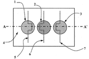
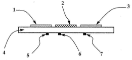
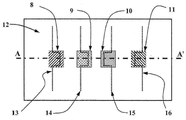
도 1 및 2에서 보이는 상기 장치는 통합된 백금을 가지는 센서 배열 및 작은 사이즈와 낮은 전력소비를 위해 제작된 온도 센서를 포함한다. 상기 배열은 두 개의 (반도체) La2CuO4 (LCO) 전극(1, 3) 및 백금(Pt) 기준 전극(2)을 직사각형의, 테이프 캐스트(taping-cast) 이트리아 안정화 지르코니아(Yttria- Stabilized-Zirconia)(YSZ) 기판(4)의 같은 면에서 포함한다. 다른 실시예에서, 모든 세 개의 전극은 LCO와 같은 하나의 물질이 될 수 있거나 각 전극은 다른 물질이 될 수 있다. 백금 저항 요소는 상기 센서 전극의 온도를 제어하고 모니터 하도록 히터(5) 및/또는 온도 센서(5,6,7)로 사용될 수 있다. 유한 요소 모델링(finite element modeling)은 상기 배열 내에서의 온도 분포를 예측하는데 사용되었다. 상기 배열은 그 후 다른 두 개의 전극들과 관련하여 LCO 전극(1)을 더 뜨겁게 유지하도록 디자인되었다. 센서 전극을 가진 가스 센서 배열이 다른 온도에서 유지되는 것이 입증된 이 장치로부터의 결과는 NO 및 NO2 농도를 선택적으로 결정할 수 있는 장치를 생산한다(yield). 이러한 가스들의 상기 개별적인 농도는 동작 중 산출될 수 있다. 센서 전극 사이의 다른 센서 전극 물질 및/또는 다른 온도차는 다른 가스들의 검출 및/또는 다른 가스들의 농도의 결정에 사용될 수 있다.The device shown in Figures 1 and 2 includes a sensor array with integrated platinum and a temperature sensor fabricated for small size and low power consumption. The arrangement is such that two (semiconductor) La 2 CuO 4 (LCO)
도 7-8에 따르면, YSZ(12)을 기초로 한 다른 가스 센서 배열은 두 개의 LCO 센서 전극 및 두 개의 백금 기준 전극을 포함한다. 상기 외부의 LCO(11) 및 백금(8) 전극이 주변 온도와 비슷하게 남아있는 동안 상기 내부의 LCO(9) 및 백금(10) 전극은 가열된다. (13, 16)이 단지 온도를 측정하기 위해서만 사용되는 반면 백금 요소(14, 15)는 가열하고 온도를 측정하는데 사용된다. 이 장치는 전극의 다수의 쌍 사이에서의 잠재적 차이를 측정하는 능력을 제공한다. 다른 실시예에서, 상기 가열 요소 및/또는 온도 센서 요소는 상기 센서 전극으로 상기 기판의 같은 표면에 위치될 수 있으며, 기판으로부터 분리될 수 있다.7-8, another gas sensor arrangement based on
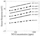
특정한 전극 온도에서의 변화 추이로부터, 상기 감도(가스 농도에서의 십진(decade) 변동당 신호에서의 mV 변동)를 나타내는 도 9-10에서의 플로트(plots)의 기울기(slopes) (및 다른 전극쌍을 위한 유사한 센서 응답 플로트)는 도 11-16의 감도 플로트를 만드는데 사용되었다. 각 라인은 다른 히터 설정치(setpoint)를 나타내어, 결과적으로 보여지는 것처럼 전극 사이의 별개의 온도차(|dT|)를 나타낸다. 이것은 네 개의 센서 전극으로부터 여섯 개의 신호 각각에 반복된다. 상기 추이 플로트에서, |dT|가 0인 경우는 상기 히터가 동작되고 있지 않은 때의 측정치를 나타낸다.9-10, which show the sensitivity (mV variation in the signal per decade change in gas concentration) from the change in the electrode at a particular electrode temperature, and the slopes of the plots in Fig. 9-10 A similar sensor response float for < RTI ID = 0.0 > a < / RTI > Each line represents a different set point of the heater, which results in a distinct temperature difference (| dT |) between the electrodes as shown. This is repeated for each of the six signals from the four sensor electrodes. In the transition float, when | dT | is 0, it represents the measured value when the heater is not operated.
도 17A는 동작 중 도 7-8의 상기 센서 배열에서의 온도 변화의 윤곽(contour) 플로트를 보여준다. 상기 플로트의 각 윤곽은 상기 장치 내의 정해진 온도를 나타낸다. 상기 장치의 중간을 통한 온도 분포는 도 17B에서 보여질 수 있다. 도 7-8의 상기 센서 배열은 손으로 만들어 졌으며, 그러므로 그 결과가 반드시 이상적인 것은 아니다. 그러므로, 각 전극은, 같은 물질로 만들어졌더라도, 서로 약간씩 차이가 있었다. 상기 전극쌍이 같은 물질로 만들어지고, 상기 히터가 동작되고 있지 않을 때, 상기 감도는 0이 되어야 한다. 하지만, 상기 플로트에서 언급한 것처럼, 상기 감도는 실제로 0이 아니다. 17A shows a contour float of the temperature change in the sensor arrangement of Figs. 7-8 during operation. Each contour of the float represents a predetermined temperature in the apparatus. The temperature distribution through the middle of the device can be seen in Figure 17B. The sensor arrangement of Figures 7-8 is made by hand, and therefore the result is not necessarily ideal. Therefore, even though the electrodes were made of the same material, they were slightly different from each other. When the electrode pairs are made of the same material and the heater is not operating, the sensitivity should be zero. However, as mentioned in the above float, the sensitivity is not actually zero.
또한, 도 9-16의 상기 플로트는 여섯 개의 독특한 신호를 만드는 각각의 전극쌍을 보여주도록 접착된다. 상기 플로트에서, 도 7-8의 전극(8, 9, 10, 11)은 백금(1), LCO(2), 백금(3) 및 LCO(4)로 각각 디자인된다. 특정한 설정치에서, 비가열 전극은 이 배열의 특정 디자인 때문에 온도를 약산 상승시키기 시작한다. 이것은 상기 비가열 전극을 가열 전극으로부터 이동하거나, 열절연벽(thermal insulation barrier)을 생성하는 등의 디자인의 작은 차이로 매우 쉽게 정정될 수 있다. 이 장치는 상기 히터 디자인 및 히터에 관련된 전극의 레이아웃, 그리고 서로 변화와 함께 향상될 수 있다. 또한, 상기 히터는 서로 다르게 배열될 수 있다. 열몰딩은 온도 균일성 관련 장치 수행에서 예상하는 것을 결정하는데 도움을 준다. In addition, the float of Figures 9-16 is glued to show each pair of electrodes making six unique signals. In the above float, the
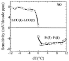
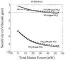
상기 LCO(4)-LCO(2) 및 백금(3)-백금(1) 전극쌍으로부터의 신호를 보여주는 도 11-12에 따르면, 상기 전극쌍의 감도는 그것들 사이의 온도차가 증가함에 따라 변동된다. LCO(4)-LCO(2)에 있어, 상기 가열 전극, LCO(2)의 온도가 상승함에 따라 상기 NO 감도가 상당히 증가한다. 사실상, 상기 전극 사이에 온도차가 존재하지 않을 때, 처음 감도의 거의 10배의 증가가 있다. 상기 히터의 설정치가 증가함에 따라, 상기 NO2 감도는 거의 0으로 감소한다. 나중 설정치에서의 감도에 있어서 약간의 증가가 있겠지만, 적어도 설정치의 작은 범위 이상, 이 전극쌍은 NO2에 민감하지 않다. 그러므로, 이 전극쌍은 단지 NO에의 감도를 보여주며, NO 선택적이어야 한다. 백금(3)-백금(1)로부터의 상기 신호는 상기 같은 물질의 개별적인 전극의 온도를 바꾸는 것에 의해 보여주며, 상기 감도는 변경될 수 있다.According to Figures 11-12, which show signals from the LCO (4) -LCO (2) and platinum (3) -platinum (1) electrode pairs, the sensitivity of the electrode pairs varies as the temperature difference between them increases . In the LCO (4) -
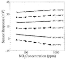
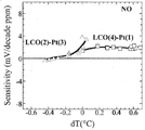
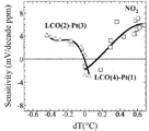
상기 LCO(2)-백금(3) 및 LCO(4)-백금(1) 전극쌍으로부터의 상기 신호를 보여주는 도 13 및 14에 따르면, 상기 전극쌍의 감도는 그것들 사이의 온도차가 증가함에 따라 변동된다. LCO(2)-백금(3)에 있어서, 상기 전극쌍은 NO에 효과적으로 민감하지 않게 되었다. 그러나, 상기 NO2 감도는 더 양성(positive)이 되며, 상기 전극 사이의 온도차가 증가함에 따라 음성 응답(negative response)으로부터 양성 응답(positive response)으로 변경한다. 그러므로, 이 전극쌍은 NO2에 선택적이다. LCO(4)-백금(1)에 있어서, 상기 NO 감도는 상기 신호가 히터 없이 동작하는 레벨에 거의 고정되게 남는다. 이것은 개별적인 전극의 온도의 변화에 의해 보여지며, 상기 감도는 다른 물질의 전극을 위해 변경될 수 있다.According to FIGS. 13 and 14 showing the above signals from the LCO (2) -platinum (3) and LCO (4) -platinum (1) electrode pairs, the sensitivity of the electrode pairs varies with the temperature difference therebetween do. In LCO (2) -platinum (3), the electrode pair became less sensitive to NO. However, the NO 2 sensitivity becomes more positive and changes from a negative response to a positive response as the temperature difference between the electrodes increases. Therefore, this electrode pair is selective for NO 2 . In the LCO (4) -platinum (1), the NO sensitivity remains nearly fixed to the level at which the signal operates without a heater. This is shown by a change in the temperature of the individual electrodes, and the sensitivity can be changed for electrodes of different materials.
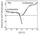
상기 LCO(4)-백금(3) 및 LCO(2)-백금(1) 전극쌍으로부터의 상기 신호를 보여주는 도 15 및 16에 따르면, 상기 전극쌍의 감도는 그것들 사이의 온도차가 증가함에 따라 변동된다. LCO(4)-백금(3)에 있어서, NO에의 상기 감도는 상기 전극 사이의 온도차 없는 조건에 관해서 거의 두 배가 된다. 또한, NO2에의 감도는 더 양성이 되며, 상기 전극 사이의 온도차가 증가함에 따라 음성 응답으로부터 양성 응답으로 된다. 이것은 상기 두 전극 사이의 어떤 온도차에서는 상기 NO2 감도가 0으로 가야 한다는 것을 나타낸다. LCO(2)-백금(1)에 있어서, 상기 NO2 감도는 상기 전극 사이의 온도차가 증가함에 따라, 점점 더 음성이 된다. 이것은 NO 및 NO2 사이의 감도에 있어서의 큰 차이가 전극쌍을 구성하는 전극의 다른 온도를 가지는 것에 의해 가능하다는 것을 보여준다.According to Figures 15 and 16, which show the signal from the LCO (4) -platinum (3) and LCO (2) -platinum (1) electrode pairs, the sensitivity of the electrode pairs varies with the temperature difference between them do. In LCO (4) -platinum (3), the sensitivity to NO is almost doubled for the temperature-free conditions between the electrodes. In addition, the sensitivity to NO 2 becomes more positive, and as the temperature difference between the electrodes increases, the negative response becomes a positive response. This indicates that the NO 2 sensitivity should go to zero at any temperature difference between the two electrodes. In LCO (2) -platinum (1), the NO 2 sensitivity becomes more and more negative as the temperature difference between the electrodes increases. This shows that the large difference in sensitivity between NO and NO 2 is possible by having different temperatures of the electrodes making up the electrode pair.
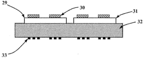
도 18에서 21은 가능한 다양한 추가 센서 실시예를 보여준다. 도 18A는 도 1, 2 및 도 7, 8에서 보여진 것과 유사한 장치의 횡단도(cross-section)를 나타낸다. 이 실시예에서, 전해질(17)은 아직도 (서로 같거나 다를 수 있는) 센서 전극(18)과 연결된다. 그러나, (히터 및/또는 온도 센서로 사용된) 백금 요소(19)는 지지 물질(support material)(20)의 위에 존재한다. 상기 지지체는 전해질층(17)과 같을 수도 있고 다를 수도 있는 전기 절연체 또는 전해질이 될 수도 있다. 상기 전해질(17) (및 부착된 센서 전극(18))은 상기 백금 요소(19)를 덮고, 상기 지지체(20)에 놓여있다. 도 18B에서 보이는 실시예는 지지체(23)의 위에 있는 전해질층(22)과 연결되어 있는 센서 전극(21)과 함께 도 18A에서 보여지는 것과 유사하다. 주요한 차이점은 상기 백금 요소(24)가 현재 상기 지지체(23)에 내장되어(embedded) 있는 것이다. 도 18C에서, 상기 장치는 위에 센서 전극(26) 및 전해질(27)을 가지는 지지 물질(25)를 포함한다. 상기 전해질층(27)은 지지체(25)와 접촉하여 있다. 백금 요소(28)는 지지체(25)의 배면에 존재한다. 도 18D는 (같은 또는 다른) 센서 전극(30)으로 구성된 하나 (또는 그 이상의) 전극쌍을 위한 하나의 전해질층(29)을 포함한다. 또한 센서 전극(30)을 가지는 다른 전해질층(31)은 전해질(29)로부터 분리되어 존재한다. 전해질층(29, 31)은 둘 다 지지체(32)의 상면에 존재한다. 배면의 백금 요소(33)는 또한 지지체 위에 존재한다. 이 배치의 다수의 조합이 가능하다.Figures 21 to 21 show various possible additional sensor embodiments. Figure 18A shows a cross-section of an apparatus similar to that shown in Figures 1, 2 and 7, In this embodiment, the
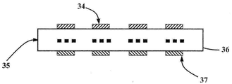
도 19는 면에 내장된 백금 요소(36)를 가지는 전해질(35)의 한 면 위에 (같거나 다른) 센서 전극(34)을 가지는 실시예의 횡단도를 보여준다. 전해질(36)의 다른 쪽 면에는 추가적인 (같거나 다른) 센서 전극(37)이 있다. 전극쌍은 센서 전극(34, 37)의 어떤 조합으로 만들어 질 수 있다. 상기 장치의 다른 쪽에 센서 전극을 갖는 것은 각 센서 전극 주변에 있는 기체환경의 분리를 초래하고, 특정한 상황에서 센서 전극을 갖는 것은 혼선의 감소 및 향상된 선택성을 가져온다. Figure 19 shows a cross-sectional view of an embodiment having (identical or different)
도 20은 상기 장치의 중간에 있는 중공 챔버(hollow chamber)를 가지는 실시예의 횡단도이다. 도 19의 실시예에서 사용된 것과 유사한 방식에서, 이 챔버는 상기 센서 전극의 환경을 분리하는 기능을 하고, 기준으로 알려진 농도의 분리된 가스 스트림을 제공하도록 사용될 수 있다. 상기 장치는 외부에 있는 (같거나 다른) 센서 전극(38) 및 중공 공간의 내부에 있는 (같거나 다른) 센서 전극(39)을 포함하고, 전해질(40)에 부착된다. 백금 요소(41)는 상기 챔버의 내부 (또는 외부)에 존재하며, 또한 전해질(40)에 부착될 수 있을 것이다. 가열 또는 온도 감지를 위한 추가적인 백금 요소는 상기 장치의 다양한 위치에 배치될 수 있을 것이다.20 is a cross-sectional view of an embodiment having a hollow chamber in the middle of the apparatus. In a manner analogous to that used in the embodiment of Figure 19, this chamber serves to separate the environment of the sensor electrode and can be used to provide a separate gas stream of known concentration as a reference. The device comprises
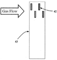
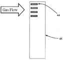
도 21A 및 21B는 상기 기판과 관련된 상기 전극 배치가 도 1, 2 및 도 7, 8에서 보이는 것과 다른 실시예의 평면도를 보여준다. 도 21A는 전해질 및/또는 구조적 지지체(43)에 맨 위의 (같거나 다른) 센서 전극(42)을 가진 실시예를 보여준다. 다른 실시예들과 비교하여, 상기 센서 전극(42)은 상기 전해질 (지지체)(43)의 상면에서 서로 엇갈리며 분리된다. 도 21B는 상기 센서 전극(44)이 도 21A에 보여지는 상기 실시예보다는 상기 전해질 및/또는 지지체(45) 및 가스 유량 방향 관련 다른 방식으로 맞춰지는(oriented) 실시예를 보여준다. 다른 실시예에서 보여지는 것들과 같은 다양한 배치 및 특징은 (히터 및/또는 온도 센서로 사용되는) 백금 요소, 다른 온도 센서 또는 냉각 요소에 사용된다. Figures 21A and 21B show a top view of an embodiment in which the electrode arrangement associated with the substrate is different from that shown in Figures 1, 2 and 7, 8. 21A shows an embodiment with the
도 22에서 31은 본 발명의 실시예에 따른 방법 및/또는 장치를 사용하는 것을 보여주는 도 7 및 8의 상기 장치로부터의 신호를 나타내며, 센서 배열은 개별 전극의 상기 온도가 변함에 따라 특정 가스 종에 선택적으로 만들어 질 수 있다. 전극과 각 전극의 절대 온도 사이의 상기 온도차는 센서 수행에 중요하다. 상기 LCO(4)-LCO(2) 신호가 도 26에서 31에서 보여지는 반면, 도 22에서 25는 LCO(2)-백금(1)에 있어서의 상기 질소산화물 가스 혼합 결과를 보여준다. Figures 22 to 31 illustrate signals from the apparatus of Figures 7 and 8 showing the use of the method and / or apparatus according to an embodiment of the present invention, . ≪ / RTI > The temperature difference between the electrode and the absolute temperature of each electrode is important for sensor performance. The LCO (4) -LCO (2) signal is shown at 31 in FIG. 26, while FIG. 22 at 25 shows the result of the nitrogen oxide gas mixing in LCO (2) -platinum (1).
도 22는 0ppm의 NO(실선) 및 200 ppm의 NO(점선)의 가스 혼합 조건에서의 NO2 가스 노출에 응답하는 LCO(2)-백금(1) 센서를 나타낸다. 상기 플로트의 횡축(x-axis)은 긴 스케일(scale)을 가진다. 정사각형, 원, 다이아몬드 기호들은 총 전력 0, ~13, 및 ~54 mW가 전극 사이에 큰 전력차(dT)를 초래하는 상기 백금 가열요소에 전달되는 조건을 나타낸다. 볼 수 있듯이, NO2에의 상기 감도(가스 농도에서의 십진(decade) 변동당 신호에서의 mV 변동)를 나타내는 라인들의 각 세트의 기울기는 히터 전력 지원과 함께 증가한다. 덧붙여서, 상기 감도는 대부분 NO2 노출 동안 NO의 추가에 의해 변경되지는 않는다. 도 23은 0ppm의 NO2(고체 라인) 및 200ppm의 NO2(대시 라인)의 NO 가스 노출에 대한 상기 센서 응답을 보여준다. 상기 플로트의 횡축은 긴 스케일을 가진다. 도 23에서 보이는 것처럼, NO에의 상기 감도는 상기 히터들에의 전력이 증가함에 따라 감소한다. 200ppm의 NO2가 상기 가스 혼합물에 추가될 때, 이 도면에 나타난 것처럼, 각 히터 설정치는 NO감도에서의 대략적인 시프트(shift)이다. 상기 시프트는 도 22에 보이는 것과 같이 NO2에의 큰 (음성) 응답을 고려할 때 예상되는 것처럼 모두 음성이다. 상기 가열 전력이 증가함에 따라, 상기 시프트는 조사된 NO 농도의 전체 범위이상으로 더 균일하게 된다. 낮은 가열 전력에서, 상기 시프트는 (상기 감도가 200ppm의 NO2의 추가와 함께 감소하는 것과 같이) 더 높은 NO 농도를 위해 더 중요해진다. 상기 히터의 사용 없이, 상기 센서 응답에서의 상기 시프트는 상기 총 NO 농도 범위를 따라 0.18에서 1.3 mV이다. 13mV의 가열 전력을 위해, 상기 시프트는 3.2 와 3.7 mW사이에 있다. 54mW에서, 상기 가열 전력은 곡선(curve)이 수평이 되는 정도까지 상기 NO 응답을 감소시키기에 충분하다. 200ppm의 NO2 가 반입될 때, 상기 곡선은 곡선으로 남아있지만, 6.8 mV까지 더 음성 값으로 이동한다. Figure 22 shows an LCO (2) -platinum (1) sensor responsive to NO 2 gas exposure at 0 ppm NO (solid line) and 200 ppm NO (dotted line) gas mixing conditions. The x-axis of the float has a long scale. Square, circle, and diamond symbols represent the conditions under which the total power of 0, ~ 13, and ~ 54 mW is delivered to the platinum heating element resulting in a large power difference (dT) between the electrodes. As can be seen, the slope of each set of lines representing the above sensitivity to NO 2 (mV variation in signal per decade variation in gas concentration) increases with heater power support. In addition, the sensitivity is largely unchanged by the addition of NO during NO 2 exposure. Figure 23 shows the sensor response for NO gas exposure of 0 ppm NO 2 (solid line) and 200 ppm NO 2 (dash line). The horizontal axis of the float has a long scale. As shown in FIG. 23, the sensitivity to NO decreases as the power to the heaters increases. When 200 ppm NO 2 is added to the gas mixture, as shown in this figure, each heater setting is a rough shift in NO sensitivity. The shift is all negative as expected when considering the large (negative) response to NO 2 , as shown in FIG. As the heating power increases, the shift becomes more uniform over the entire range of irradiated NO concentrations. At low heating power, the shift becomes more important for higher NO concentrations (such that the sensitivity decreases with the addition of 200 ppm NO 2 ). Without the use of the heater, the shift in the sensor response is from 0.18 to 1.3 mV along the total NO concentration range. For 13 mV of heating power, the shift is between 3.2 and 3.7 mW. At 54 mW, the heating power is sufficient to reduce the NO response to such an extent that the curve is horizontal. When 200 ppm of NO 2 is brought in, the curve remains curved but moves to a negative value up to 6.8 mV.
도 24는 0ppm의 NO에 있어 도 22와 같은 조건을 가진 상기 NO2 센서 응답을 보여준다. 그러나, 상기 횡축은 직선(linear) 스케일을 가지고 있고, 이 플로트는 0ppm의 NO2 의 조건에 있어서의 데이터 포인트를 포함한다. 또한 도 24에 나타난 것처럼, 0ppm의 NO2의 기준치(baseline) 및 200ppm의 NO2 가스 스텝 사이의 측정된 전압차에 있어서의 차이이다. 도 23에서의 NO에 있어서의 결과(0ppm 및 200ppm 의 NO2)가 0ppm의 NO2의 기준치(baseline) 및 200ppm의 NO2 가스 스텝 사이의 전압에 있어서의 변화와 비교 될 때(도 24), 증가된 가열 전력과 함께 NO2 감도의 향상이 명백하다. 상기 히터의 사용 없이, NO가 또한 상기 가스 혼합물에 존재할 때 이 두 개의 조건 사이에 0.18 에서 1.3mV의 시프트가 있는 반면(도 23), 0ppm으로부터 200ppm으로의 NO2 변화는 3.5mV의 전압의 변화를 발생한다(도 24). 측정된 실제 전압은 예상되었던 것과 다르기 때문에, 이 차이는 가스 혼합물에서 NO 및/또는 NO2 가스 농도를 결정하려고 할 때 신중히 생각될 수 있다. 작은 양의 전력이 상기 히터에 전달될 때 (~13mW), 5 mV의 전압에서의 상기 예상된 변화(도24)와 NO 및 NO2 가 존재할 때 보이는 3.2에서 3.7mV의 실제적인 변화(도 23)를 비교해볼 때 입증되듯이 상기 상황은 약간 향상한다. 상기에서 언급했듯이, 54mW의 전력을 전달하는 가열 설정치는 증가된 NO2 감도(도 22)및 NO 감도의 완전한 제거(도 23의 수평인 곡선)를 초래한다. 또한, 0ppm 및 200ppm 의 NO2 조건 사이의 상기 예상된 전압 변화는 6.5mV이다(도 24). 이것은 측정이 또한 0ppm 및 200ppm의 NO2 가 있는 데서 만들어질 때, NO 가스 노출 동안의 상기 시프트(6.8 mV)와 거의 정확하게 일치한다. NO 및 NO2의 가스 혼합물은 NO2 변화에의 상기 예상된 전압 변화에 영향을 미치지 않고, 상기 가스 센서 배열은 상기 가스 혼합물에 존재하는 NO2 가스의 실제 농도를 정확히 나타내는데 사용될 수 있다. 같은 원리를 사용해, 상기 센서 배열은 NO, NO2, NH3, CO, CO2 및 탄화수소와 같은 가스의 향상된 감도를 가지도록 만들어질 수 있다. FIG. 24 shows the NO 2 sensor response with the condition as shown in FIG. 22 at 0 ppm NO. However, the abscissa has a linear scale, and this float contains data points in the condition of NO 2 at 0 ppm. Also shown in Figure 24 is the difference in the measured voltage difference between the baseline NO 2 of 0 ppm and the NO 2 gas step of 200 ppm. Also result in a NO at 23 (0ppm and 200ppm of NO 2) (Fig. 24) when compared to the change in the voltage between 0ppm of NO 2 reference values (baseline), and 200ppm of NO 2 gas step, An increase in NO 2 sensitivity with increased heating power is evident. Without the use of the heater, there is a shift of 0.18 to 1.3 mV between these two conditions when NO is also present in the gas mixture (Fig. 23), while the NO 2 change from 0 ppm to 200 ppm is a change in voltage of 3.5 mV (Fig. 24). Since the measured actual voltage is different from what was expected, this difference can be considered carefully when trying to determine the NO and / or NO 2 gas concentration in the gas mixture. When a small amount of power is delivered to the heater (~ 13 mW), the expected change (Fig. 24) at a voltage of 5 mV and the actual change from 3.2 to 3.7 mV when NO and NO 2 are present ), The situation is slightly improved. As mentioned above, the heating set point delivering 54 mW of power results in increased NO 2 sensitivity (FIG. 22) and complete removal of NO sensitivity (horizontal curve in FIG. 23). Also, the expected voltage change between 0 ppm and 200 ppm NO 2 conditions is 6.5 mV (Fig. 24). This is almost exactly the same as the shift (6.8 mV) during NO gas exposure when the measurement is also made with 0 ppm and 200 ppm NO 2 . The gas mixture of NO and NO 2 does not affect the expected voltage change to NO 2 change and the gas sensor arrangement can be used to accurately represent the actual concentration of NO 2 gas present in the gas mixture. Using the same principle, the sensor arrangement can be made to have enhanced sensitivity of gases such as NO, NO 2, NH 3 , CO, CO 2 and hydrocarbons.
도 25는 나타나 있는 것처럼, NO(0 및 200ppm의 NO2) 및 NO2(0 및 200ppm의 NO)의 가스 혼합물 조건을 가지는 도 7 및 8에서의 실시예의 LCO(2)- 백금(1) 신호를 위한 총 가열 전력 대 감도의 플로트를 보여준다. NO2 와 함께 그리고 NO2 없이 NO에의 상기 감도는 상기 가열 전력이 상승함에 따라, 0 mV/십진 ppm의 NO로 감소한다. 이 현상이 발생함에 따라, 200ppm의 NO2가 상기 가스 혼합물에 반입될 때 보여지는 감도의 변화에서의 감소도 또한 있다. NO2 와 함께 그리고 NO2 없이 NO에의 상기 감도는 상기 가열 전력이 상승함에 따라, 0 mV/십진 ppm의 NO로 감소한다. 상기 가열 전력이 상승함에 따라, NO와 함께 그리고 NO 없이 NO2에의 상기 감도는 거의 2인자(factor)만큼 증가한다. 0ppm 및 200ppm의 NO를 가지는 NO2에의 상기 감도는 가열 전력의 같은 범위를 넘어 거의 변하지 않은 채 남아있다. 또한, (가열 전력의 54 mW와 함께 얻어지는) 최대의 dT에서 이 전극쌍을 작동하는 것에 의해, NO에의 교차 감도가 제거 되기 때문에 (0 또는 음성이 됨), NO2에의 높음 감도 및 선택성을 가지는 센서가 획득된다. 전에 언급되었듯이, 이러한 감도의 변화 및 NO 및 NO2의 가스 혼합물의 노출과 함께 관찰된 상기 전압 변화를 고려 할 때, 전체적인 센서 배열 수행은 본 방법의 실시예를 사용하여 향상될 수 있음이 명백하다.As shown in FIG. 25, the LCO (2) -platinum (1) signal of the embodiment in FIGS. 7 and 8 with gas mixture conditions of NO (0 and 200 ppm NO 2 ) and NO 2 (0 and 200 ppm NO) Lt; / RTI > for a total heating power versus sensitivity for < RTI ID = 0.0 > NO 2 And this sensitivity to NO with NO 2 decreases to 0 mV / decimal ppm NO as the heating power rises. As this phenomenon occurs, there is also a reduction in the change in sensitivity seen when 200 ppm of NO 2 is introduced into the gas mixture. NO 2 And this sensitivity to NO with NO 2 decreases to 0 mV / decimal ppm NO as the heating power rises. As the heating power increases, NO and NO The sensitivity to NO 2 increases by almost a factor of two. This sensitivity to NO 2 with 0 ppm and 200 ppm NO remains almost unchanged over the same range of heating power. In addition, by operating this electrode pair at maximum dT (obtained with 54 mW of the heating power), cross sensitivities to NO are eliminated (zero or negative), so that high sensitivity and selectivity to NO 2 A sensor is obtained. As mentioned previously, it is evident that the overall sensor array performance can be improved using an embodiment of the present method, taking into account such changes in sensitivity and the voltage changes observed with exposure of the gas mixture of NO and NO 2 Do.
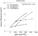
도 26에서 28은 NO 및 NO2가 함께 가스 혼합물에 존재 할 때, 도 7 및 8의 실시예의 상기 LCO(4)-LCO(2) 전극쌍이 어떻게 총 질소산화물 농도를 검출하는데 사용될 수 있는지를 보여준다. 0ppm의 NO(고체 라인) 및 200 ppm의 NO(대시 라인)의 가스 혼합 조건에서의 NO2 가스 노출에의 상기 LCO(4)-LCO(2) 응답은 나타나있는 총 가열 전력 0, 13 및 54 mW로 도 26에서 보여진다. 같은 총 가열전력에 있어서, 도 27은 0ppm의 NO2(고체 라인) 및 200ppm의 NO2(대시 라인)의 가스 혼합 조건에서의 NO 가스 노출에의 응답을 보여준다. 도 26 및 27에 따르면, NO2 (0 및 200ppm 의 NO) 가스 혼합물에의 상기 응답은 항상 양성 응답을 보여준다. NO에 필수적으로 감도가 있지는 않은, 상기 히터가 사용되지 않을 때 (0mW의 총 가열전력)를 제외하고는 NO(0 및 200ppm 의 NO2) 가스 혼합물에도 같다. 또한, LCO(4)-LCO(2) 신호에서의 상기 시프트는 도 26과 같이 NO가 NO2 가스 스텝에 반입될 때 및 도 27과 같이 NO2 가 NO 가스 스텝에 추가될 때 항상 양성이다. 도 26 및 27 둘 다의 경우에 응답하는 시프트가 있을 때, 상기 기울기는 더 좋은 총 가열 전력 세팅에서도 비교적 변함없이 남아있다. 이것은 도 28에서 감도의 플로트(0 mV/십진 ppm의 NO 또는 NO2) 대 NO(0 및 200ppm 의 NO2) 및 NO2 (0 및 200ppm 의 NO)에의 총 가열전력을 보여준다. 또한, NO 및 NO2 둘 다의 상기 감도는 LCO(2) 전극의 온도가 증가함에 따라 총 가열전력의 증가와 함께 증가한다. NO 및 NO2 농도의 각 결합물을 위해 특별한 전압차가 발생된다. 이것은 상기 센서 응답 대 0mW, 13mW, 및 54mW 각각의 가스 혼합물에서의 총 ppm 질소산화물을 보여주는 도 29에서 31에 나타나있다. 상기 히터가 사용되지 않는 경우 (도 29), 상기 LCO(4)-LCO(2) 신호는 NO에 민감하지 않고 NO2 에 감도를 가진다. 그러므로, 이러한 조건하에서, 상기 LCO(4)-LCO(2) 전극쌍은 NO2 에 선택적이다. 그러나, 도 29에서 31에서 입증되듯이, 상기 가열된 LCO(2) 전극의 온도가 증가하면 (상기 가열 전력이 공급될 때), 상기 신호가 NO2 에 민감하게 남아있는 동안 NO에 민감하게 됨에 따라 상기 총 질소산화물 측정이 가능해진다. 도 30 및 31을 비교하면, 상기 가열 전력이 더 증가함에 따라, NO 및 NO2에의 상기 감도는 심지어 더 증가한다. 또한, NO(0 및 200ppm 의 NO2) 및 NO2 (0 및 200ppm 의 NO)를 포함한 상기 가스 혼합물 측정 사이에는 겹침이 있다. 예를 들어, 400ppm의 총 질소산화물 농도에서 (200ppm 의 NO 및 200ppm의 NO2), 상기 센서 응답은 상기 측정이 고정된 NO 농도를 가진 NO2의 동적인 가스 스텝에서 만들어지거나 그 반대로 되는 것과 상관없이 정확히 같다. 요약하면, 적어도 하나의 센서 전극의 온도를 다른 것과 바꾸는 것에 의해, 상기 전극쌍을 구성하는 각 전극을 위해 같은 물질을 사용할 때라도 NO 및 NO2의 가스 혼합물에서의 총 질소산화물을 측정하는 것이 가능해진다. 26 shows how the LCO (4) -LCO (2) electrode pair of the embodiment of FIGS. 7 and 8 can be used to detect the total nitrogen oxide concentration when NO and NO 2 are present together in the gas mixture . The LCO (4) -LCO (2) response to NO 2 gas exposure under the gas mixing conditions of 0 ppm NO (solid line) and 200 ppm NO (dash line) mW. < / RTI > In the same total heating power, 27 is NO in the gas mixture condition of the NO 2 (solid line) and NO 2 (dashed line) of a 200ppm 0ppm It shows the response to gas exposure. According to Figs. 26 and 27, NO 2 (NO of 0 and 200ppm) shows the response of the gas mixture are always positive response. (0 and 200 ppm of NO 2 ) gas mixture, except that the heater is not used (0 mW total heating power), which is not essentially sensitive to NO. Further, the shift in the LCO (4) -LCO (2) signal is always positive when NO is introduced into the NO 2 gas step as shown in FIG. 26 and when NO 2 is added to the NO gas step as in FIG. In the case of both Figures 26 and 27, when there is a shift to respond, the slope remains relatively unchanged even at better total heating power settings. This shows the total heating power to a float of sensitivity (0 mV / decade ppm NO or NO 2 ) vs. NO (0 and 200 ppm NO 2 ) and NO 2 (0 and 200 ppm NO) in FIG. In addition, the sensitivity of both NO and NO 2 increases with increasing total heating power as the temperature of the LCO (2) electrode increases. A special voltage difference is generated for each combination of NO and NO 2 concentrations. This is shown in Figures 29 to 31 showing the total ppm nitrogen oxides in the gas mixture for each of the sensor responses versus 0mW, 13mW, and 54mW. If the heater is not being used (FIG. 29), the LCO (4) -LCO (2) signal has a sensitivity for NO 2 not sensitive to NO. Therefore, under these conditions, the LCO (4) -LCO (2) electrode pair is selective for NO 2 . However, as evidenced in Figures 29 to 31, when the temperature of the heated LCO (2) electrode is increased (when the heating power is supplied), the signal is sensitive to NO while remaining sensitive to NO 2 So that it becomes possible to measure the total nitrogen oxide. Comparing Figures 30 and 31, as the heating power further increases, the sensitivity to NO and NO 2 increases even more. There is also overlap between the gas mixture measurements, including NO (0 and 200 ppm NO 2 ) and NO 2 (0 and 200 ppm NO). For example, at a total nitrogen oxide concentration of 400 ppm (200 ppm NO and 200 ppm NO 2 ), the sensor response is correlated with the measurement being made in the dynamic gas step of NO 2 with a fixed NO concentration or vice versa Exactly the same. In summary, by changing the temperature of at least one sensor electrode to another, it becomes possible to measure the total nitrogen oxide in the gas mixture of NO and NO 2 even when using the same material for each electrode constituting the electrode pair .
도 22에서 31에서 보이는 것과 같이, 도 7 및 8의 실시예 및 유사한 센서 배열은 NO 및 NO2의 개별적인 농도를 측정할 수 있다. 이것은 상기 LCO(2) 전극이 가까이에서 가열될 때, 상기 LCO(2)-백금(1) 전극쌍이 질소산화물 가스 혼합물에서의 NO 이상의 NO2를 선택적으로 검출할 수 있기 때문에 가능하다. 덧붙여서, 같은 물질이지만 다른 온도를 가진 두 개의 센서 전극을 구성하는 LCO(4)-LCO(2) 전극쌍은 총 질소산화물을 검출할 수 있다. NO의 농도는 상기 검출된 질소산화물 농도로부터 상기 검출된 NO2 농도를 빼는 것에 의해서 계산된다. 이 방법은 간접적이지만, 유사한 또는 다른 온도의 전극쌍을 구성하는 개별적인 전극을 가까이에서 가열하는 같은 방법을 사용하는 것이 가능하며, 전극쌍은 도 9에서 16에서 나타난 것처럼 NO, NO2, (또는 CO, CO2, 암모니아 및 다른 가스들)의 선택적인 검출을 제공할 수 있다.As seen in Figures 22 to 31, the embodiments of Figures 7 and 8 and similar sensor arrangements can measure the individual concentrations of NO and NO 2 . This, the LCO (2) when the LCO (2) electrode is heated in a close-platinum is possible because (1) the electrode pair can be selectively detected by the NO over NO 2 in NOx gas mixture. In addition, the LCO (4) -LCO (2) electrode pair, which comprises two sensor electrodes of the same material but different temperatures, can detect total nitrogen oxides. The concentration of NO is calculated by subtracting the detected NO 2 concentration from the NOx concentration detected. This method is indirect, but it is possible to use the same method of closely heating the individual electrodes constituting the electrode pairs at similar or different temperatures, and the electrode pairs can be used for NO, NO 2 , (or CO , CO 2, ammonia, and other gases).
본 명세서 내에 포함되어 있음.Are included herein.
도 1은 본 발명에 따른 장치의 특정 실시예를 보여준다.
도 2는 도 1의 상기 실시예의 횡단면도를 보여준다.
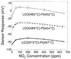
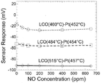
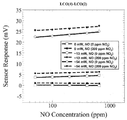
도 3은 세 개의 센서 전극으로부터의 비가열 LCO 전극 대 비가열 백금 전극에 있어서의 센서 응답 대 NO2의 농도를 보여준다.
도 4는 세 개의 센서 전극으로부터의 가열된 LCO 전극 대 비가열 백금 전극에 있어서의 센서 응답 대 NO2의 농도를 보여준다.
도 5는 세 개의 센서 전극으로부터의 가열된 LCO 전극 대 비가열 백금 전극에 있어서의 센서 응답 대 NO2의 농도를 보여준다.
도 6은 세 개의 센서 전극으로부터의 비가열 LCO 전극 대 비가열 백금 전극에 있어서의 센서 응답 대 NO2의 농도를 보여준다.
도 7은 본 발명의 추가 실시예를 보여준다.
도 8은 도 7의 상시기 실시예의 횡단면도를 보여준다.
도 9는 온도차 상승 결과를 보여주는, 비가열 LCO 센서 전극 및 가열된 백금 센서 전극, LCO(4)-백금(3)을 가지는 전극쌍에 있어서의 센서 응답 대 NO2의 농도를 보여준다.
도 10은 온도 상승 결과를 보여주는, 비가열 LCO 센서 전극 및 가열된 백금 센서 전극, LCO(4)-백금(3)을 가지는 전극쌍에 있어서의 센서 응답 대 NO2의 농도를 보여준다.
도 11은 NO 가스 농도의 변화에 응하는 도 7 및 8의 실시예의 LCO(4)-LCO(2) 및 백금(3)-백금(1) 전극쌍으로부터의 신호 결과를 보여준다.
도 12는 NO2 가스 농도의 변화에 응하는 도 7 및 8의 실시예의 LCO(4)-LCO(2) 및 백금(3)-백금(1) 전극쌍으로부터의 신호 결과를 보여준다.
도 13은 NO 가스 농도의 변화에 응하는 도 7 및 8의 실시예의 LCO(2)-백금(3) 및 LCO(4)-백금(1) 전극쌍으로부터의 신호 결과를 보여준다.
도 14는 NO2 가스 농도의 변화에 응하는 도 7 및 8의 실시예의 LCO(2)-백금(3) 및 LCO(4)-백금(1) 전극쌍으로부터의 신호 결과를 보여준다.
도 15는 NO 가스 농도의 변화에 응하는 도 7 및 8의 실시예의 LCO(4)-백금(3) 및 LCO(2)-백금(1) 전극쌍으로부터의 신호 결과를 보여준다.
도 16은 NO2 가스 농도의 변화에 응하는 도 7 및 8의 실시예의 LCO(4)-백금(3) 및 LCO(2)-백금(1) 전극쌍으로부터의 신호 결과를 보여준다.
도 17A는 도 7 및 8에서 보여지는 실시예에 있어 온도 윤곽 플로트를 보여준다.
도 17B는 도 17A의 횡단면을 통해 온도 분포를 보여준다.
도 18A는 다수의 전극쌍이 존재할 상면에 놓인 내장된 히터 및 센서 전극을 가지는 구조적 지지체 및 전해질에 대한 실시예를 보여준다.
도 18B는 다수의 전극쌍이 존재할 상면에 놓인 내장된 히터, 전해질 및 센서 전극을 가지는 구조적 지지체에 대한 실시예를 보여준다.
도 18C는 다수의 전극쌍이 존재할 배면 히터 및 상면에 놓인 전해질 및 센서 전극을 가지는 구조적 지지체에 대한 실시예를 보여준다.
도 18D는 다수의 전극쌍 및 전해질층이 존재할 배면 히터 및 다른 전극쌍에 있어 센서 전극을 가지는 분리된 전해질층을 가지는 구조적 지지체에 대한 실시예를 보여준다.
도 19는 다수의 전극쌍 및 전해질층이 존재할 내장된 히터 및 상기 전해질의 반대편에 있는 센서 전극을 가지는 전해질 지지체에 대한 실시예를 보여준다.
도 20은 기준 가스를 위해 사용될 수 있는 챔버의 한 면에는 히터가, 다른 면에는 센서 전극이, 그리고 외부에는 추가 센서 전극이 높여진 상기 구조적 지지체 내부의 하나 또는 그 이상의 챔버에 대한 실시예를 보여준다.
도 21A는 상기 전해질 및/또는 구조적 지지체의 상면에서 서로 스태거되며 분리된 센서 전극에 대한 실시예를 보여준다.
도 21B는 가스 유량 방향 관련 다른 방식으로 맞춰지는 센서 전극의 실시예를 보여준다.
도 22는 총 가열전력의 다양한 다른 예에 관한 도 9에서 16 보다 높은 주위 온도에서 검사되며, 검사되는 조건은 0ppm의 NO 및 200ppm의 NO 가스 혼합물을 가지는 NO2 가스 스텝을 포함하는, 도 7 및 8에서의 실시예의 LCO(2)-백금(1) 전극쌍에 있어 NO2의 센서 응답의 (긴 스케일) 플로트를 보여준다.
도 23은 총 가열전력의 다양한 다른 예에 관한 도 9에서 16 보다 높은 주위 온도에서 검사되며, 검사되는 조건은 0ppm의 NO 및 200ppm의 NO2 가스 혼합물을 가지는 NO2 가스 스텝을 포함하고 NO 가스 스트림에의 NO2 반입에 응하는 시프트 또한 표시되는, 도 7 및 8에서의 실시예의 LCO(2)-백금(1) 전극쌍에 있어 NO 의 센서 응답의 (긴 스케일) 플로트를 보여준다.
도 24는 각 가열 전력 조건에 표시된 0 에서 200 ppm의 NO2 로부터의 전압 변화를 가지는 도 7 및 8의 실시예와 관련된 도 22의 (직선 스케일) 플로트를 보여준다.
도 25는 도 22 및 23에서 나온, 도 7 및 8의 실시예와 관련된 감도 대 LCO(2)-백금(1) 전극쌍의 총 가열전력을 보여준다.
도 26은 총 가열전력의 다양한 다른 예에 관련된 도 9에서 16 보다 더 높은 주위 온도에서 검사되는 도 7 및 8의 실시예의 LCO(4)-LCO(2)의 NO 응답을 보여준다.
도 27은 총 가열전력의 다양한 다른 예에 관련된 도 9에서 16 보다 더 높은 주위 온도에서 검사되는 도 7 및 8의 실시예의 LCO(4)-LCO(2)의 NO2 응답을 보여준다.
도 28은 도 26 및 27에서 나온, 도 7 및 8의 실시예와 관련된 감도 대 LCO(4)-LCO(2) 전극쌍의 총 가열전력을 보여준다.
도 29는 히터의 사용 없이 (예를 들어, 총 가열전력이 0mW), 도 7 및 8의 실시예와 관련된 LCO(4)-LCO(2) 전극쌍의 총 질소산화물 감지능력을 나타낸다.
도 30은 총 가열 전력 13mW의, 도 7 및 8의 실시예와 관련된 LCO(4)-LCO(2) 전극쌍의 총 질소산화물 감지능력을 나타낸다.
도 31은 총 가열 전력 54mW의, 도 7 및 8의 실시예와 관련된 LCO(4)-LCO(2) 전극쌍의 총 질소산화물 감지능력을 나타낸다.Figure 1 shows a specific embodiment of an apparatus according to the invention.
Figure 2 shows a cross-sectional view of the embodiment of Figure 1;
Figure 3 shows the density of the sensor response for NO 2 in the non-heated platinum electrode LCO electrode for a non-heat from the three sensor electrodes.
Figure 4 shows the density of the sensor response for NO 2 in the heated LCO electrode for non-heating the platinum electrode from the three sensor electrodes.
Figure 5 shows the density of the sensor response for NO 2 in the heated LCO electrode for non-heating the platinum electrode from the three sensor electrodes.
FIG. 6 shows the sensor response versus NO 2 concentration for the non-heated LCO electrode versus non-heated platinum electrode from the three sensor electrodes.
Figure 7 shows a further embodiment of the invention.
Figure 8 shows a cross-sectional view of the same embodiment of Figure 7;
FIG. 9 shows the sensor response versus NO 2 concentration in an electrode pair having a non-heated LCO sensor electrode and a heated platinum sensor electrode, LCO (4) -platinum (3), showing the temperature difference rise.
Figure 10 shows the sensor response versus NO 2 concentration in an electrode pair with a non-heated LCO sensor electrode and a heated platinum sensor electrode, LCO (4) -platinum (3), showing the temperature rise results.
Figure 11 shows the signal results from the LCO (4) -LCO (2) and platinum (3) -platinum (1) electrode pairs of the embodiments of Figures 7 and 8 in response to changes in NO gas concentration.
Figure 12 shows the signal results from the LCO (4) -LCO (2) and platinum (3) -platinum (1) electrode pairs of the embodiments of Figures 7 and 8 in response to changes in NO 2 gas concentration.
Figure 13 shows the signal results from the LCO (2) -platinum (3) and LCO (4) -platinum (1) electrode pairs of the embodiments of Figures 7 and 8 in response to changes in NO gas concentration.
Figure 14 shows the signal results from the LCO (2) -platinum (3) and LCO (4) -platinum (1) electrode pairs of the embodiments of Figures 7 and 8 in response to changes in the NO 2 gas concentration.
Figure 15 shows the signal results from the LCO (4) -platinum (3) and LCO (2) -platinum (1) electrode pairs of the embodiments of Figures 7 and 8 in response to changes in NO gas concentration.
Figure 16 shows the signal results from the LCO (4) -platinum (3) and LCO (2) -platinum (1) electrode pairs of the examples of Figures 7 and 8 in response to changes in NO 2 gas concentration.
17A shows a temperature contour plot for the embodiment shown in FIGS. 7 and 8. FIG.
Figure 17B shows the temperature distribution over the cross-section of Figure 17A.
18A shows an embodiment of a structural support and an electrolyte having an embedded heater and sensor electrode on an upper surface where a plurality of electrode pairs are present.
18B shows an embodiment of a structural support having an embedded heater, an electrolyte and a sensor electrode on top of which a plurality of electrode pairs are present.
18C shows an embodiment of a structural support having a backside heater on which a plurality of electrode pairs are to be present and an electrolyte and a sensor electrode on the upper surface.
18D shows an embodiment of a structural support having a separate electrolyte layer with sensor electrodes in a pair of electrode pairs and a rear heater in which a plurality of electrode pairs and an electrolyte layer are present.
19 shows an embodiment of an electrolyte support having a built-in heater in which a plurality of electrode pairs and an electrolyte layer are present, and a sensor electrode on the opposite side of the electrolyte.
Figure 20 shows an embodiment of one or more chambers in the structural support with a heater on one side of the chamber that can be used for the reference gas, a sensor electrode on the other side, and an additional sensor electrode on the outside .
FIG. 21A shows an embodiment of a sensor electrode that is staggered and separated from the upper surface of the electrolyte and / or the structural support.
Fig. 21B shows an embodiment of a sensor electrode adapted in a different way in relation to the gas flow direction.
22 is in Fig. 9 related to a variety of other example of the total heating power is scanned in high ambient temperature above 16, the conditions to be tested comprises a NO 2 gas step with the NO gas mixture of NO and 200ppm of 0ppm, 7 and (Long scale) float of the sensor response of NO 2 in the LCO (2) -platinum (1) electrode pair of the example in FIG.
23 is different, and tests in the high ambient temperatures in Figure 9 according to another example greater than 16, the condition to be tested is the NO gas including NO 2 gas step with the NO 2 gas mixture of NO and 200ppm of 0ppm stream of the total heating power (Long scale) float of the sensor response of NO in the LCO (2) -platinum (1) electrode pair of the embodiment of FIGS. 7 and 8, where the shift in response to NO 2 entry into NO 2 is also indicated.
Figure 24 shows in Fig. 22 related to the embodiment of Figures 7 and 8 has a voltage change from NO 2 from 0 to 200 ppm above each heating power condition (linear scale) float.
Fig. 25 shows the total heating power of the sensitivity vs. LCO (2) -platinum (1) electrode pair associated with the embodiment of Figs. 7 and 8, from Figs. 22 and 23;
Fig. 26 shows the NO response of LCO (4) -LCO (2) of the embodiment of Figs. 7 and 8 being examined at ambient temperatures higher than 16 in Fig. 9 relative to various other examples of total heating power.
Figure 27 shows the NO 2 response of LCO (4) -LCO (2) of the embodiment of Figures 7 and 8 being examined at an ambient temperature higher than 16 in Figure 9 relative to various other examples of total heating power.
Figure 28 shows the total heating power of the sensitivity vs. LCO (4) -LCO (2) electrode pair associated with the embodiment of Figures 7 and 8, from Figures 26 and 27;
Figure 29 shows the total nitrogen oxide sensing capability of the LCO (4) -LCO (2) electrode pair associated with the embodiment of Figures 7 and 8 without the use of a heater (e.g., total heating power of 0 mW).
Figure 30 shows the total nitrogen oxide sensing capability of the LCO (4) -LCO (2) electrode pair, associated with the embodiment of Figures 7 and 8, with a total heating power of 13 mW.
Figure 31 shows the total nitrogen oxide sensing capability of the LCO (4) -LCO (2) electrode pair, associated with the embodiment of Figures 7 and 8, with a total heating power of 54 mW.
본 발명의 실시예들은 가스 센서 및 하나 또는 그 이상의 가스를 감지하는 방법과 관련되어 있으며, 구체적인 실시예들은 전위 가스 센서 및 하나 또는 그 이상의 가스를 감지하는 방법을 포함한다. 추가적은 실시예들은 전류 측정에 관한/또는 임피던스 가스 센서 및 하나 또는 그 이상의 가스를 감지하는 방법에 관련되어 있다. 하나의 실시예는 유사한 또는 다른 온도에서 유지되는 센서 전극 배열을 포함하며, 상기 장치의 감도 및 종 선택성은 센서 전극의 다른 쌍 사이에서 잘 조정될 수 있다. 특정의 실시예는 연소 배기가스 및/또는 반응 부산물을 모니터링 하도록 가스 센서 배열을 포함한다. 본 장치의 하나의 실시예는 높은 온도에서 동작하며 거친 화학 환경을 견딜 수 있는 본 발명과 관련된다. Embodiments of the present invention relate to a gas sensor and a method of sensing one or more gases, the specific embodiments including a method of sensing a potential gas sensor and one or more gases. Additional embodiments relate to current measurement and / or methods of sensing an impedance gas sensor and one or more gases. One embodiment includes a sensor electrode array maintained at a similar or different temperature and the sensitivity and species selectivity of the device can be well coordinated between the other pair of sensor electrodes. Certain embodiments include a gas sensor arrangement to monitor combustion exhaust gases and / or reaction byproducts. One embodiment of the present apparatus relates to the present invention which operates at high temperatures and can withstand harsh chemical environments.
본 장치의 실시예들은 상기 전극들이 동일 평면상에 있는 것을 허여하여, 같은 환경에서 센서 전극을 가질 수 있다. 이러한 전극들의 감도 및 선택성은 온도와 함께 달라질 수 있다. 그러므로, 특정의 실시예 관련하여, 상기 장치의 온도는 필요할 때 정확하게 제어되고, 빠르게 변화될 수 있다. 관심 있는 하나 또는 그 이상의 가스 종을 모니터 할 수 있는 장치를 달성하기 위해서, 센서 전극 배열이 포함될 수 있다. 상기 배열 신호는 그 후 하나 또는 그 이상의 개별적인 종의 존재 및/또는 농도를 결정하도록 직선 알고리즘 (또는 다른 적합한 알고리즘)에 들어가질 수 있다. 패턴 인식은 달성되기 쉬운 일이 아니며, 추가적인 전극을 요구할 수도 있어서 상기 장치의 비용을 빠르게 끌어올릴 수 있기 때문에, 최소의 간섭과 함께 다른 것들이 있을 때에는, 단일 종을 개별적으로 모니터링 하는 능력을 가지는 것이 더 좋을 것이다. 이렇게 하여, 만약 전혀 없다면, 상기 장치는 광범위한 패턴 인식을 요구하지 않을 것이다. Embodiments of the present apparatus may allow the electrodes to be on the same plane and thus have sensor electrodes in the same environment. The sensitivity and selectivity of these electrodes may vary with temperature. Therefore, with respect to a specific embodiment, the temperature of the apparatus can be accurately controlled and changed quickly as needed. To achieve an apparatus capable of monitoring one or more gas species of interest, a sensor electrode arrangement may be included. The array signal may then enter a linear algorithm (or other suitable algorithm) to determine the presence and / or concentration of one or more individual species. Pattern recognition is not easy to achieve and may require additional electrodes so that the cost of the device can be increased quickly so that when there are others with minimal interference, will be good. In this way, if not at all, the device will not require extensive pattern recognition.
본 발명의 실시예들은 개별 센서 전극 및/또는 전체 장치의 열 변경을 통해 선택성 및 감도의 향상을 제공할 수 있다. 또한 신호 잡음에 있어서의 향상은 만약 상기 온도가 균일하게 유지되면 달성될 수 있다. 또한, 본 장치의 실시예에의 온도 제어 결합과 함께, 전극 중독 또는, 시간이 흐르면서 센서 수행에 변화 또는 상기 장치의 완전한 실패를 초래하는 다른 현상들은 감소되거나 서로 바꿀 수 있다.Embodiments of the present invention can provide selectivity and sensitivity enhancement through thermal modification of the individual sensor electrodes and / or the entire device. The improvement in signal noise can also be achieved if the temperature is maintained uniform. In addition, with temperature control coupling to embodiments of the present apparatus, electrode poisoning or other phenomena that cause changes in sensor performance over time or a complete failure of the apparatus can be reduced or interchanged.
본 방법 및 장치는 연소 부산물 또는 화학/가스 모니터링 과정을 모니터링하는데 사용될 수 있다. 특정 실시예에서, 상기 장치는 촉매 변환기가 제대로 작동하는지를 결정하거나 운전 조건이 달라짐에 따라 변하는 EPA (또는 다른) 요구조건을 기초로 한 엔진에서 공연비를 조절하도록 정보를 제공하기 위해 자동차의 배기가스를 모니터 하는데 사용될 수 있다. 본 장치는 또한 동력 장치 또는 어떤 산업 제조 공정에서의 연소 부산물 (또는 다른 화학/가스 관련 공정)을 모니터 하도록 사용될 수도 있을 것이다.The method and apparatus may be used to monitor combustion byproducts or chemical / gas monitoring processes. In a particular embodiment, the apparatus is adapted to control the air-fuel ratio in an engine based on an EPA (or other) requirement that determines whether the catalytic converter is operating properly or changes as operating conditions change, Can be used for monitoring. The apparatus may also be used to monitor combustion devices (or other chemical / gas related processes) in a power plant or in any industrial manufacturing process.
본 발명에 따른 센서 배열의 실시예는 통합된 백금 히터 및 작은 사이즈와 낮은 전력소비를 위해 제작된 온도 센서를 포함한다. 상기 배열은 두 개의 La2CuO4 전극 및 백금 기준 전극을 직사각형의, 테이프 캐스트 YSZ 기판의 같은 면에서 포함한다. 백금 저항 요소는 상기 센서 전극의 온도를 제어하고 모니터 하도록 히터 및/또는 온도 센서로 사용될 수 있다. 유한 요소 모델링은 상기 배열 내에서의 온도 분포를 예측하는데 사용되었다. 상기 배열은 그 후 다른 두 개의 전극들과 관련하여 La2CuO4 전극을 더 뜨겁게 유지하도록 디자인되었다. 센서 전극을 가진 가스 센서 배열이 다른 온도에서 유지되는 것이 입증된 이 장치로부터의 결과는 NO 및 NO2 농도를 선택적으로 결정할 수 있는 장치를 생산한다(yield). 추가 실시예에서, 센서 배역의 선택성은 상기 센서 전극의 국부 온도의 제어를 통해 향상될 수 있다.Embodiments of the sensor arrangement according to the present invention include an integrated platinum heater and a temperature sensor fabricated for small size and low power consumption. The arrangement comprises two La 2 CuO 4 electrodes and a platinum reference electrode on the same side of a rectangular, tape cast YSZ substrate. The platinum resistance element may be used as a heater and / or temperature sensor to control and monitor the temperature of the sensor electrode. Finite element modeling was used to predict the temperature distribution within the array. The arrangement was then designed to keep the La 2 CuO 4 electrode hotter with respect to the other two electrodes. The result from this device, which has been proven to maintain a gas sensor array with sensor electrodes at different temperatures, yields a device that can selectively determine NO and NO 2 concentrations. In a further embodiment, the selectivity of the sensor region can be improved through control of the local temperature of the sensor electrode.
상기 센서 전극의 국부 온도의 제어는 열에 더하여 또는 열 대신에 냉각에 의해서 실시될 수 있다. 통상적으로 알려진 수동 및/또는 능동 냉각은 본 발명에 포함될 수 있다.The control of the local temperature of the sensor electrode can be carried out by cooling in addition to or instead of heat. Conventional passive and / or active cooling may be included in the present invention.
센서 전극은 백금과 같은 금속, La2CuO4 또는 WO3 등의 반도체 산화물과 같은 반도체 또는 가스에 감도를 보여주는 다른 물질로 만들어 질 수 있다. 일반적으로, 어떤 정해진 센서 전극 물질은 다른 가스 종들에 상기 전극의 온도에 따라 변화하는 감도 및 선택성을 가질 것이다. 변동하는 감도 및/또는 선택성의 정도는 상기 물질, 가스 및 온도에 달려있다. 각 전극은 하나 또는 그 이상의 전극쌍의 한 부분이다. 이것은 신호의 측정 가능한 숫자가 센서 전극의 실제 숫자보다 커질 수 있음을 의미한다. 특히, 상기 센서 배열의 디자인은 (개별적인 장치로 또는 단일한 장치에 함께 있는) 두 개의 다른 전극쌍 방법(scheme)을 포함할 수 있다. 하나의 방법은 같은 그리고/또는 다른 온도에서 유지될 수 있는 다수의 물질을 동시에 사용할 수 있다. 상기 온도의 제어는 가열 및/또는 냉각 기술을 통해 달성될 수 있다. 장치는 또한 하나 또는 그 이상의 다른 온도에서 유지되는 상기 동일한 물질의 다수의 전극을 포함할 수도 있다. 상기 동일한 물질의 전극은 만약 미세구조, 사이즈, 또는 두께와 같은 상기 전극의 하나 또는 그 이상의 다른 특징들이 다른 전극과 달라질 수 있다면 같은 온도에서 유지될 수도 있을 것이다. 따라서, 상기 가스 센서 배열은 응용에 따라 단일한 장치에서 이러한 방법들 중 하나 또는 그 이상을 사용할 수도 있을 것이다. The sensor electrode may be made of a metal such as platinum, a semiconductor oxide such as La 2 CuO 4 or WO 3 Semiconductor or other material that exhibits sensitivity to gases. In general, any given sensor electrode material will have sensitivity and selectivity to other gas species that varies with the temperature of the electrode. The degree of varying sensitivity and / or selectivity depends on the material, gas and temperature. Each electrode is a part of one or more electrode pairs. This means that the measurable number of signals can be larger than the actual number of sensor electrodes. In particular, the design of the sensor arrangement may include two different electrode pair schemes (either as individual devices or together in a single device). One method can use multiple materials simultaneously, which can be maintained at the same and / or different temperatures. Control of the temperature can be achieved through heating and / or cooling techniques. The apparatus may also comprise a plurality of electrodes of the same material held at one or more different temperatures. The electrode of the same material may be maintained at the same temperature if one or more other features of the electrode, such as microstructure, size, or thickness, may differ from the other electrode. Thus, the gas sensor arrangement may use one or more of these methods in a single device depending on the application.
본 발명에 따른 가스 센서는 개별 센서 전극의 상면의 온도를 제어하도록 특별히 디자인된 가열 요소를 포함할 수 있다. 하나의 실시예에서, 상기 센서 전극은 기판의 상면에, 상기 가열 요소는 기판의 배면에 존재한다. 다른 실시예에서, 상기 센서 전극은 상기 기판의 두 개의 면에 다 존재한다. 예를 들어, 상기 기판은 YSZ 기판 또는 다른 전해질이 될 수 있다. 상기 기판은 위에 전해질 층을 가지는 Al2O3와 같은 구조적 지지체도 될 수 있다. 상기 가열 요소는 거친 환경에서 시간이 흐름에 따라 감소되지 않도록 열과 화학 안정성을 가지고 있는, 백금과 같은 물질로 만들어 질 수 있다. 상기 가열 요소는 저항기로 작동할 수 있으며, 상기 가열 요소를 통한 전자 전류를 지남에 의한 줄 가열을 통해 열을 생성한다.The gas sensor according to the invention may comprise a heating element specifically designed to control the temperature of the top surface of the individual sensor electrodes. In one embodiment, the sensor electrode is on the top surface of the substrate, and the heating element is on the back side of the substrate. In another embodiment, the sensor electrode is present on two sides of the substrate. For example, the substrate may be a YSZ substrate or other electrolyte. The substrate may also be a structural support, such as Al 2 O 3 , having an electrolyte layer thereon. The heating element may be made of a material such as platinum, which has thermal and chemical stability such that it does not decrease over time in harsh environments. The heating element may operate as a resistor and generate heat through line heating by passing electron current through the heating element.
*본 발명의 다양한 실시예에 따르면, 상기 기판을 위해 다양한 전해질 물질이 사용될 수 있고, 다양한 물질이 상기 센서 전극에 사용될 수 있으면, 어떤 가열 요소도 사용될 수 있다. 적절한 물질의 예는 여기서 전체적으로 참고로 포함된 U.S. 6,598,596에서 가르쳐 준다. 상기 전극은 금속과 반도체 포함 다양한 물질로 만들어질 수 있다. 상기 반도체 물질은 금속산화물 또는 금속산화물 화합물이다. "금속산화물" 및 "금속산화물 화합물"의 용어는 O2와 결합된 성분 금속을 가지는 화합물을 의미하도록 여기서 교체될 수 있게 사용된다. 본 발명에 유용한 금속산화물의 예는 SnO2, TiO2, TYPd5, MoO3, ZnMoO4 (ZM), WO3, WR3, La2CuO4 및 이것들의 혼합물을 포함한다. 상기 반도체 물질은 하나의 금속산화물을 포함할 수 있다. 상기 금속산화물은 SnO2, TiO2, TYPd5, MoO3, ZnMoO4 (ZM) 또는 WO3 이며, TYPd5 및 WR3는 아래 정의되어 있는 약자이다. 약자 TYPd5는 여기서 약 85:10:5의 중량비에서 TiO2(티타니아), Y2O3(산화이트륨) 및 백금을 선택하는 것에 의해 준비된 합성물을 나타낸다.According to various embodiments of the present invention, various electrolyte materials may be used for the substrate, and any heating element may be used provided that various materials can be used for the sensor electrode. Examples of suitable materials are described in U.S. Pat. 6,598,596. The electrodes can be made of various materials including metals and semiconductors. The semiconductor material is a metal oxide or a metal oxide compound. The terms "metal oxide" and "metal oxide compound" are used interchangeably herein to mean a compound having a constituent metal associated with O2. Examples of metal oxides useful in the present invention include SnO2, TiO2, TYPd5, MoO3, ZnMoO4 (ZM), WO3, WR3, La2CuO4, and mixtures thereof. The semiconductor material may comprise one metal oxide. The metal oxide is SnO2, TiO2, TYPd5, MoO3, ZnMoO4 (ZM) or WO3, and TYPd5 and WR3 are abbreviations defined below. The abbreviation TYPd5 represents a composite prepared by selecting TiO2 (titania), Y2O3 (yttria) and platinum in a weight ratio of about 85: 10: 5.
상기 전해질은 산소 이온 전도성(oxygen ion-conducting) 전해질이다. 상기 산소 이온 전도성 전해질은 ZrO2, Bi2O3 또는 CeO2를 기본으로 할 수 있다. 선호되는 산소 이온 전도성 전해질은 ZrO2, Bi 2O3 또는 CeO2과, 안정제(stabilizers)로써 기능할 수 있는 칼시아(CaO) 및 산화이트륨(Y2O3)과 같은 도판트(dopant) 등의 일반적인 기본 물질 또는 다른 적합한 산소 이온 투과성 물질을 포함하는 전해질 혼합물이다. 예를 들어, 이트리아 안정화 지르코니아(YSZ) 전해질은 산화이트륨과 ZrO2의 혼합에 의해 형성될 수 있다. 할로겐화물과 같은 산소 이온보다 이온성 종을 전도하는 전해질은 통상적으로 잘 알려져 있으며, 할로게이 포함된 가스 종을 측정하기 위해 본 발명에서 효율을 찾는다. 전해질을 위한 물질의 선택은 측정될 가스 혼합물에서의 요소에 달려있다. 그러므로, 예를 들어 NOx, COx or SOx와 같은 산화물 요소의 농도를 측정하기 위해, 전해질은 산소 이온 전도성 전해질이 된다. 선호되는 산소 이온 전도성 전해질은 지르코니아(ZrO 2), 창연 산화물(Bi2 O3) 및 산화세륨(CeO 2)을 기본으로 한 전해질 혼합물이다. 실질적인 전해질 혼합물은 일반적으로 칼시아(CaO) 및 산화이트륨(Y2O3)과 같은 하나 또는 그 이상의 도판트(dopant), 또는 다른 적합한 산소 이온 투과성 물질을 포함한다.The electrolyte is an oxygen ion-conducting electrolyte. The oxygen ion conductive electrolyte may be based on ZrO2, Bi2O3 or CeO2. The preferred oxygen ion conducting electrolyte is a general base material such as ZrO2, Bi2O3 or CeO2 and a dopant such as calcia (CaO) and yttria (Y2O3) that can function as stabilizers, And an oxygen ion permeable substance. For example, the yttria-stabilized zirconia (YSZ) electrolyte can be formed by mixing yttrium oxide with ZrO2. Electrolytes that conduct ionic species more than oxygen ions, such as halides, are commonly well known and find efficiency in the present invention to measure gas species containing halo. The choice of material for the electrolyte depends on the element in the gas mixture to be measured. Thus, for example, to measure the concentration of oxide elements such as NOx, COx or SOx, the electrolyte becomes an oxygen ion conducting electrolyte. The preferred oxygen ion conducting electrolyte is an electrolyte mixture based on zirconia (ZrO 2), bismuth oxide (Bi 2 O 3) and cerium oxide (CeO 2). Substantial electrolyte mixtures generally include one or more dopants, such as calcia (CaO) and yttria (Y2O3), or other suitable oxygen ion permeable materials.
가스 센서 배열의 특정 실시예는 두 개의 LCO 센서 전극 및 두 개의 백금 기준 전극을 포함한다. 상기 외부의 LCO 및 백금 전극이 주변 온도와 비슷하게 남아있는 동안 상기 내부의 LCO 및 백금 전극은 가열된다. 또한, 전극의 다수의 쌍 사이에서의 잠재적 차이는 신호를 제공하기 위해 측정될 수 있다. 두 개의 전극이 물질 및 동작 온도의 동일한 결합을 가지고 있지 않기 때문에, 네 개의 전극을 짝 짓는 것에 의해 측정될 수 있는 총 6개의 별개의 신호가 있다. 이 신호들은 가스의 혼합물에서의 가스 농도를 결정하는데 돕도록 비교될 수 있다.A particular embodiment of a gas sensor arrangement comprises two LCO sensor electrodes and two platinum reference electrodes. The internal LCO and platinum electrodes are heated while the external LCO and platinum electrodes remain close to ambient temperature. In addition, potential differences between multiple pairs of electrodes can be measured to provide a signal. Since the two electrodes do not have the same bond of material and operating temperature, there are a total of six distinct signals that can be measured by pairing the four electrodes. These signals can be compared to help determine the gas concentration in the mixture of gases.
이 장치들에서의 상기 온도 제어는 중요해질 수 있다. 최소의 변동에 대한 온도의 정확한 조절은 상기 장치가 안정적인 센서 신호를 발생하게 할 수 있다. 그러므로, 열 모델링은 상기 센서 전극의 다른 위치에 대한 상기 장치에서의 온도 분포 및 상기 배열 기판에서의 상기 가열 전극에 관한 정보를 제공하도록 설계 단계 동안 수행될 수 있다.The temperature control in these devices can be significant. Accurate adjustment of the temperature to minimal variations can cause the device to generate a stable sensor signal. Thermal modeling can therefore be performed during the design phase to provide temperature distribution in the device to other locations of the sensor electrode and information about the heating electrode in the array substrate.
백금은 가열 요소 및 온도 센서의 제조를 위해 사용될 수 있다. 백금은 내구성 및 화학, 열 안정성 때문에 고온의 저항온도 장치(RTD)의 산업 기준 및 가스 센서에서의 가열 요소로 될 수 있다. 그러나, 다른 물질들은 본 장치에서 히터로서 사용될 것이다.Platinum can be used for the production of heating elements and temperature sensors. Because of its durability and chemical and thermal stability, platinum can be a heating element in industrial standards and gas sensors of high temperature resistance temperature devices (RTD). However, other materials will be used as heaters in this device.
표면 온도 측정은 어려울 수 있고, 가능한 몇몇의 최선의 방법은 광학 적외선 센서(optical infrared sensors)및 RTD의 사용을 포함한다. 아래 약 400℃의 백금 저항은 온도에서 직선 의존성(linear dependence)을 가진다. 그러나, 이 온도 이상은, 추가 열 손실이 실험 데이터로부터 벗어나도록 상기 직선 모형(linear model)을 초래하고, 대체 모형은 a, b 및 c가 실험에 의한 계수인 R(T) = a(l + bT - cT2 )(1) 이다. 상기 데이터가 상기 모형에 맞춰진 후에, 소프트웨어는 (1)과 상기 백금 요소의 저항 측정으로부터 상기 계수를 이용하여 센서 동작 동안 상기 표면온도를 계산할 수 있다.Surface temperature measurements can be difficult, and some of the best possible methods involve the use of optical infrared sensors and RTDs. The platinum resistance at about 400 ° C below has a linear dependence on temperature. However, above this temperature, the linear model results in the additional heat loss deviating from the experimental data, and the alternative model assumes that R (T) = a (l + bT - cT 2 ) (1). After the data is fitted to the model, the software can calculate the surface temperature during sensor operation using (1) and the coefficient from the resistance measurement of the platinum element.
가열 요소는 다른 대상을 가열하는 동시에 온도 센서로 사용될 수 있다. 만약 상기 히터의 저항이 예를 들어 4선법을 사용하여 정확히 결정될 수 있다면, 상기 백금 요소의 온도가 산출될 수 있다. 전압으로 증가된 저항은 줄 가열 때문에 상기 히터에 공급된다. 이것은 전압 또는 전류 측정에 큰 영향을 주지는 않는다. 즉, 상기 측정은 회로에서의 실제 전류 및 상기 히터를 가로지르는 전압 강하를 나타낸다. 그러므로 상기 히터의 측정된 저항 및 온도는 실제의 값을 나타낸다. The heating element can be used as a temperature sensor while heating other objects. If the resistance of the heater can be accurately determined, for example, using a four-wire method, the temperature of the platinum element can be calculated. The increased resistance to voltage is supplied to the heater due to the line heating. This does not have a significant effect on the voltage or current measurement. That is, the measurement represents the actual current in the circuit and the voltage drop across the heater. Therefore, the measured resistance and temperature of the heater represent actual values.
상기 가열 요소 형태는 온도 분배에 중요하다. 하나의 실시예에서, 상기 센서 전극의 온도는 균일하거나, 필요하다면 선호되는 방법에서 균일하지 않다. 하나의 실시예에서, 상기 가열 요소는 C-형태 이다. 구불구불한 형태의 히터 또한 사용될 수 있다. 나선형 또는 다른 형태의 히터도 사용될 수 있다. 상기 가열 요소는 전압에 적용되거나 전류에 적용되는 것에 의해 제어될 수 있다. 사용된 상기 가열 요소를 제어하는 방법은 응용에 달려있다. 하나의 예로, 자동차에서, 자동차의 배터리는 상기 가열 요소가 전압 제어 되는 것과 같이 전력원이 될 수 있다.The heating element configuration is important for temperature distribution. In one embodiment, the temperature of the sensor electrode is uniform, or is not uniform in the preferred method if desired. In one embodiment, the heating element is C-shaped. A serpentine type heater may also be used. Helical or other types of heaters may also be used. The heating element can be controlled by being applied to a voltage or applied to a current. The method of controlling the heating element used depends on the application. As an example, in a vehicle, a battery of an automobile can be a power source such that the heating element is voltage controlled.
특정 실시예에서, YSZ 기판은 한 면에 다수의 센서 전극을 가질 수 있다. 백금 (또는 다른 저항력이 있는 물질) 요소는 상기 전극과 나란히 있는 상기 YSZ 기판의 반대 면에 있다. 상기 센서 전극은 서로 대칭적(symmetric)이거나 비대칭적인(nonsymmetrical) 방식으로 맞춰질 수도 있으며, 그것들은 스태거된다. 상기 백금 (또는 다른 저항력이 있는 물질) 요소는 히터로 사용되지 않을 필요가 있다. 상기 백금 요소는 히터 및/또는 온도 센서로 사용될 수도 있을 것이다. 다른 실시예에서, 반도체 요소는 예를 들어 열전 냉각(thermoelectric cooling)을 통해 상기 전극의 냉각에 사용될 수 있다. 상기 냉각 요소는 어떤 물질이라도 상기 장치에서 특정 지역을 냉각하게 만들어 질 수도 있다. 상기 가열/냉각 요소 및/또는 표면 온도 센서의 열 특성은 상기 장치 구조에 통합된 단열 물질의 사용 또는, 다른 특정 형태 또는 빈 용량(empty volumes)과 같은 상기 장치의 열 속성에 영향을 주는 상기 장치에의 디자인 변경에 의해 향상될 수 있다. 상기 기판의 형태 또한 변할 수 있다.In certain embodiments, the YSZ substrate may have multiple sensor electrodes on one side. A platinum (or other resistive material) element is on the opposite side of the YSZ substrate that is in line with the electrode. The sensor electrodes may be aligned symmetrically or nonsymmetrical to one another and they are staggered. The platinum (or other resistive material) element need not be used as a heater. The platinum element may be used as a heater and / or a temperature sensor. In another embodiment, the semiconductor element may be used to cool the electrode, for example, via thermoelectric cooling. The cooling element may be made to cool certain areas of the device with any material. The thermal characteristics of the heating / cooling element and / or the surface temperature sensor may be determined by the use of an insulating material incorporated in the device structure or by the device which affects the thermal properties of the device such as other specific forms or empty volumes. By design changes to < / RTI > The shape of the substrate may also vary.
도 1은 본 발명에 따른 장치의 특정 실시예를 보여주며, 도 2는 같은 실시예의 횡단면도를 보여준다. 상기 장치는 상기 기판이 전해질인 기판의 제 1면 사이에서 백금 전극을 가지는 두 개의 La2CuO4 전극을 포함한다. 백금 히터 및 두 개의 백금 온도 센서 요소는 상기 기판의 다른 면에 위치될 수 있다. 도 3-6은 세 개의 센서 전극으로부터의 두 개의 다른 전극쌍에 있어서의 센서 응답 대 NO 및 NO2의 농도를 보여준다. 이 결과는 상기 장치가 주로 NO2에 민감했던 신호 및 NO 및 NO2 둘 다에 민감했던 신호를 발생할 수 있음을 보여준다. 그러므로, NO 및 NO2의 개별 농도의 간접적인 검출은 감산(substraction)을 통해 가능해진다. Fig. 1 shows a specific embodiment of the device according to the invention, and Fig. 2 shows a cross-sectional view of the same embodiment. The apparatus comprises two La 2 CuO 4 electrodes having a platinum electrode between the first side of the substrate where the substrate is an electrolyte. A platinum heater and two platinum temperature sensor elements may be located on the other side of the substrate. Figure 3-6 shows the sensor response versus the concentration of NO and NO 2 in the two different electrode pairs from the three sensor electrodes. The results show that the device may occur mainly the signal that is sensitive to signals, and NO and NO 2 were sensitive to both NO 2. Therefore, the indirect detection of the individual concentrations of NO and NO 2 is possible through subtraction.
도 7은 본 발명의 다른 특정 실시예를 보여주며, 도 8은 같은 실시예의 횡단면도를 보여준다. 상기 장치는 기판의 한 면에서 서로 맞물려있는 두 개의 La2CuO4 전극 및 두 개의 백금 전극을 포함한다. 전해질을 포함하는 상기 기판의 다른 쪽 면에는 네 개의 백금 전극이 있는데, 내부의 두 개는 히터 및 온도 센서이며, 외부의 두 개는 온도 센서이다. 이 배열은 두 개의 LCO 전극이 다른 온도에서 유지되게 하며, 두 개의 백금 센서 전극이 다른 온도에 있게 한다. 만약 상기 두 개의 가열된 전극이 변함없는 온도에서 유지된다면, 이것은 신호를 받기 위한 여섯 개의 전극쌍 조합을 허여한다. 만약 상기 가열된 전극이 동작 중 더 많은 온도를 가지게 디자인 된다면, 출력 센서 신호를 제공할 목적으로 두 개의 전극으로 기능할 두 개의 다른 온도에서의 특정 전극을 가지는 더 많은 전극쌍 조합이 발생될 수 있다. 도 9-10은 온도차 상승 결과 및 각 전극의 절대 온도를 보여주는 비가열 LCO 전극 및 가열된 백금 전극을 가지는 전극쌍에 있어서의 NO 및 NO2를 위한 센서 응답을 보여준다. 상기 감도(가스 농도에서의 십진(decade) 변동당 신호에서의 mV변동)를 나타내는 도 9-10에서의 플로트의 기울기는 도 11-16에서 제공된 추이 플로트를 만들도록 쓰일 수 있다. 각 곡선은 다른 히터 설정치를 나타내어, 결과적으로 도 7-8에서 보여지는 것처럼 상기 장치의 전극 사이의 다른 온도차(|dT|)를 나타낸다. 이것은 도 7-8에서 보여지는 상기 장치의 네 개의 센서 전극으로부터 여섯 개의 전극 신호 각각을 위해 반복된다. 상기 추이 플로트에서, |dT|가 0과 같은 곡선은 상기 히터가 동작되고 있지 않은 경우이다.FIG. 7 shows another specific embodiment of the present invention, and FIG. 8 shows a cross-sectional view of the same embodiment. The apparatus comprises two La 2 CuO 4 electrodes and two platinum electrodes interdigitated on one side of the substrate. On the other side of the substrate containing the electrolyte there are four platinum electrodes, two of which are the heater and the temperature sensor, and the other two are the temperature sensors. This arrangement allows the two LCO electrodes to be maintained at different temperatures and the two platinum sensor electrodes at different temperatures. If the two heated electrodes are maintained at an unaltered temperature, this allows for a combination of six electrode pairs to receive the signal. If the heated electrode is designed to have more temperature during operation, more electrode pair combinations with specific electrodes at two different temperatures to serve as two electrodes for the purpose of providing an output sensor signal may be generated . Figures 9-10 show the sensor response for NO and NO 2 in a pair of electrodes with a non-heated LCO electrode and a heated platinum electrode showing the temperature difference rise and the absolute temperature of each electrode. The slope of the float in Figs. 9-10, which represents the sensitivity (mV variation in signal per decade variation in gas concentration), can be used to make the transition float provided in Figs. Each curve represents another heater setting, resulting in a different temperature difference (| dT |) between the electrodes of the device as shown in FIGS. 7-8. This is repeated for each of the six electrode signals from the four sensor electrodes of the device shown in Figures 7-8. In the transition float, a curve where | dT | is equal to 0 is a case where the heater is not operated.
도 7-8에서 보여지는 상기 장치 관련, 상기 장치 자체에서의 센서 전극의 숫자보다 더 많은 센서 신호가 측정될 수 있다. 이것은 몇몇의 전극이 다른 온도에 있기 때문에 가능하다. 또한, 상기 장치는 NO에만 선택적인 전극쌍 및 NO2에만 선택적인 다른 전극-쌍을 가질 수 있다. 다른 실시예들은 CO 및 CO2와 같은 다른 가스에 선택적인 전극쌍을 가질 수 있다. 사실상, 상기 몇몇의 히터 설정치에 있어, 상기 전극쌍이 더 양성이 되거나 더 음성이 됨에 따라 그것들의 신호 방향을 바꾸는 예가 있었다. 이것은 정해진 전극 물질 또는 물질쌍을 나타내며, 만약 상기 온도가 그것들 사이에서 다르게 유지된다면, 상기 전극쌍은 그것이 하나 또는 그 이상의 가스에 민감하거나 민감하지 않게 하는 방법으로 사용될 수 있을 것이다.More sensor signals can be measured than the number of sensor electrodes in the device itself, relative to the device shown in Figures 7-8. This is possible because some of the electrodes are at different temperatures. In addition, the device may have other pairs of electrodes that are selective only for NO, and other pairs that are selective for NO 2 only. Other embodiments may have selective electrode pairs in other gases such as CO and CO 2 . In fact, in some of the above heater settings, there was an example of changing the signal direction of the electrode pairs as they became more positive or more negative. This represents a defined electrode material or substance pair, and if the temperature is maintained different between them, the electrode pair may be used in such a way that it is not sensitive or sensitive to one or more gases.
또한, 상기 센서는 절대 온도의 변화 및 전극쌍을 구성하는 전극 사이의 온도의 차이 등 두 개의 변화라는 이점을 가질 수 있다. 일반적으로 정해진 종에의 감도는 높은 온도에서 변경된다. 만약 두 개의 센서 전극이 그것들이 더 이상 하나의 가스에는 민감하지 않지만 다른 가스에는 민감한 온도 이상에 있게 된다면, 상기 신호는 선택적일 것이다. 추가로, 만약 두 개의 전극 중 하나의 온도가 더 상승한다면, 선택적인 상기 신호는 상기 전극의 개별적인 전위(potentials)가 바뀜에 따라 감도의 증가로부터 이익이 될 수 있다. 이것은 어떻게 상기 센서 전극의 감도가 온도와 함께 변하고 상기 전극의 특정 가스 종이 노출되는가에 기반을 두어 이점이 될 수 있다. 특정 실시예에서, 패턴 인식이 사용되지 않아서, 장치 비용은 감소하고, 센서 수행은 향상된다. 상기 수행은 또한 전극 사이에서의 온도차를 달성하기 위해 같은 방법을 사용하여 상기 몇몇의 전극쌍의 감도를 증가시키는 것이 가능하기 때문에 향상된다. 이것은 또한 장치의 미세구조 및 기하학적 구조의 변화에 의해서도 이루어질 수 있다.In addition, the sensor may have the advantage of two changes, such as a change in absolute temperature and a difference in temperature between the electrodes constituting the electrode pair. In general, the sensitivity to a given species changes at high temperatures. If the two sensor electrodes are not sensitive to one gas anymore but are above a sensitive temperature in another gas, the signal will be optional. Additionally, if the temperature of one of the two electrodes rises further, the optional signal can benefit from an increase in sensitivity as the individual potentials of the electrode change. This can be advantageous based on how the sensitivity of the sensor electrode changes with temperature and the specific gas species of the electrode is exposed. In certain embodiments, pattern recognition is not used, the cost of the device is reduced, and sensor performance is improved. This performance is also improved because it is possible to increase the sensitivity of some of the electrode pairs using the same method to achieve the temperature difference between the electrodes. This can also be achieved by changes in the microstructure and geometry of the device.
본 발명의 다양한 실시예에서 사용된 센서 전극의 상기 배열은 다양한 다른 센서 전극을 포함할 수 있다. 필요하다면, 기준 또는 유사 기준전극이 포함될 수 있다. 실시예들에서, 각 센서 전극은 "센서 전극쌍"을 구성하도록 사용될 수 있다. 또한, 각 센서 전극은 다수의 전극쌍을 구성하도록 상기 배열에서 다른 센서 전극과 결합하여 사용될 수 있다. 다른 전극 구조 및 속성은 상기 센서가 수행하는 방법을 변경할 것이다. 이것은 특정의 응용을 위해 요구되는 수행(예, 감도, 선택성 및 응답 시간)을 달성하도록 상기 장치의 특정 방식(tailoring)을 허여한다.The arrangement of sensor electrodes used in various embodiments of the present invention may include various other sensor electrodes. If necessary, a reference or similar reference electrode may be included. In embodiments, each sensor electrode can be used to construct a "sensor electrode pair ". In addition, each sensor electrode can be used in combination with other sensor electrodes in the array to form a plurality of electrode pairs. Other electrode structures and attributes will change the way the sensor performs. This allows tailoring of the device to achieve the required performance (e.g., sensitivity, selectivity and response time) for a particular application.
특정 디자인 및/또는 응용에 따라서, 상기 센서 전극은 같거나 다른 전극 물질을 사용하고, 같고/같거나 다른 미세구조를 사용하고, 같고/같거나 다른 기하학적 구조(형태 및 두께)를 사용하고/또는 같고/같거나 다른 온도에서 동작되고 있도록 구성될 수 있다. 전해질이 상기 두 개의 전극과 접촉할 때, 센서 전극쌍을 생성하는데 사용될 두 개의 전극은, 측정될 가스 종 또는 측정될 가스 종을 포함하는 가스의 혼합물에 노출될 때, 상기 센서 전극쌍을 가로질러 전압 포텐셜을 생성해야 한다는 것이 핵심이다. 몇몇의 다른 미세구조의 조합을 가지는 두 개의 전극을 가지는 것에 의해, 다른 기하학적 구조 (형태 및 두께), 다른 물질, 다른 온도에서 존재하는 것, 및/또는 어떤 점에서는 상기 물질을 다르게 하는 다른 변화, 센서 전극쌍을 생성하는 조건은 존재할 수 있다.Depending on the particular design and / or application, the sensor electrodes may be of the same or different electrode material, using the same / same or different microstructure, using the same / same or different geometry (shape and thickness) and / May be configured to be operated at the same / same or different temperature. When the electrolyte is in contact with the two electrodes, the two electrodes to be used to generate the sensor electrode pair are exposed to a mixture of gases to be measured or to a gas mixture to be measured, The key is to create a voltage potential. By having two electrodes having a combination of several different microstructures, it is possible to have different geometries (shape and thickness), different materials, existing at different temperatures, and / or other changes that make the material different in some respects, There may be conditions that create a sensor electrode pair.
상기 센서 전극의 온도 제어는 요구되는 수행을 달성하기 위해 사용될 수 있다. 상기 센서 전극쌍에 따라, 상기 측정된 신호의 실행은 일반적으로 열 변화를 통해 변경될 수 있다. 또한, 상기 온도는 (가스 스트림에서의 변화와 같은) 외부 소스로 인한 변화로부터 더 유지된다. 그러므로, 상기 장치의 실시예들은 상기 센서 전극의 온도를 모니터하는 수단 및 필요 시 그것들의 온도를 변경할 수 있는 수단을 포함한다.The temperature control of the sensor electrode can be used to achieve the required performance. Depending on the sensor electrode pair, the performance of the measured signal can generally be changed through a thermal change. In addition, the temperature is further maintained from changes due to external sources (such as changes in the gas stream). Therefore, embodiments of the apparatus include means for monitoring the temperature of the sensor electrodes and means for changing their temperature, if necessary.
*가열 요소는 필요 시 상기 센서 전극의 온도를 변화시키도록 사용될 수 있다. 상기 가열 요소는 특정의 센서 전극과 거의 나란히 있는 센서 전극으로부터의 기판의 반대 면에 위치될 수 있다. 가열 요소는 상기 센서 전극과 마찬가지로 상기 기판의 같은 면에 위치될 수 있다. 가열 요소는 상기 전해질 또는 지지체의 안이나 위에 내장될 수 도 있다. 다른 가열 요소 패턴은 상기 장치에서 이상적인 열 배분을 생성하기 위해 (예를 들어 C 형태, 나선형 또는 구불구불한 패턴으로) 구현될 수 있다. 상기 열은 줄 가열 (열=전력*시간=전류2*저항*시간)에 의해서 생성될 수 있다. 상기 가열 전류는 펄스로(in pulse) 또는 변경없는 방법으로 제어되고 전달되는 전압 또는 전류일 수도 있다. 상기 가열 전류는 단순 전류 분리 또는 상기 가열 요소에의 개별적인 (전류 또는 전압) 출력에 의해 전달 될 수 있다. The heating element can be used to change the temperature of the sensor electrode if necessary. The heating element may be located on the opposite side of the substrate from the sensor electrode substantially in line with the specific sensor electrode. The heating element may be located on the same side of the substrate as the sensor electrode. The heating element may be embedded in or on the electrolyte or support. Other heating element patterns may be implemented (e.g., in C-shaped, spiral, or serpentine pattern) to create an ideal heat distribution in the apparatus. The heat can be generated by string heating (heat = power * time = current 2 * resistance * time). The heating current may be a voltage or current that is controlled and transferred in pulse or unchanged manner. The heating current may be delivered by simple current isolation or by a separate (current or voltage) output to the heating element.
상기 센서 전극의 온도는 또한 열과의 결합 또는 홀로 냉각을 통해 제어될 수 있다. 하나의 실시예에서, 냉각은 예를 들어 고체 상태 가열 펌프와 같은 열전 냉각으로 알려진 방법을 사용하여 달성될 수 있다. 냉각은 또한 열흡수원(heat sinks)의 사용으로 달성될 수 있다. 상기 장치의 다른 부분의 온도를 변화시키는 것에 의해, 센서 전극 하의 온도는 낮아질 수도 있을 것이다. 상기 장치의 특정 지역의 냉각을 달성하기 위해 다른 디자인들 또한 가능하다.The temperature of the sensor electrode can also be controlled through coupling with heat or by cooling down alone. In one embodiment, cooling may be accomplished using a method known as thermo-cooling, such as, for example, a solid state heat pump. Cooling can also be achieved by the use of heat sinks. By changing the temperature of the other part of the device, the temperature under the sensor electrode may be lowered. Other designs are also possible to achieve cooling of a particular area of the device.
온도 모니터링은 저항의 측정 또는, 금속, 반도체나 상기 센서 전극 아래의 또는 가까운 구역을 커버하는 다른 물질로 구성된 요소의 다른 온도 관련 매개 변수(parameter)의 측정에 의해 달성될 수 있다. 온도 센서는 또한 내장되거나 표면에 노출되어 놓일 수도 있다. 온도 감지의 다수의 방법은 RTD 및 열전대의 사용을 포함하여 가능하다. 온도 센서는 가열 요소로 기능하는 동시에 요소로 분리된다. 온도 센서는 냉각 또는 가열 요소로도 동시에 기능한다.Temperature monitoring can be accomplished by measuring the resistance or by measuring other temperature-related parameters of the element consisting of metal, semiconductor, or other material covering the near or near area of the sensor electrode. The temperature sensor may also be embedded or exposed to the surface. Multiple methods of temperature sensing are possible including the use of RTDs and thermocouples. The temperature sensor functions as a heating element and is separated into elements. The temperature sensor functions simultaneously as a cooling or heating element.
모니터 될 수 있는 다수의 다른 신호가 있다. 모니터 될 수 있는 다양한 신호 중 몇몇은 센서 전극의 전압 및/또는 센서 전극쌍의 전압차를 포함한다. 다중화(multiplexing)는 대응하는 다수의 센서 전극쌍으로부터 다수의 전압 신호를 모니터 하도록 사용될 수 있다. 온도 센서의 저항 또는 다른 매개 변수 모니터링은 또한 달성될 수 있으면, 다중화를 사용할 수도 있다.There are a number of other signals that can be monitored. Some of the various signals that can be monitored include the voltage of the sensor electrode and / or the voltage difference of the sensor electrode pair. Multiplexing can be used to monitor multiple voltage signals from a corresponding plurality of sensor electrode pairs. The resistance of the temperature sensor or other parameter monitoring may also be used if multiplexing can be achieved.
다수의 실시예들은 상기 센서 관련 전기적 특성을 측정하는 검출기를 포함한다. 상기 센서 배열에 있어서의 하나의 검출 방법은 전위차일 것이다. 상기 배열은 전도계량(conductimetric) (또는 임피던스계량(impedancemetric)), 용량성(capacitive)과 같은 다른 검출 방법, 또는 가스 종을 검출하는 다른 방법을 포함 할 수도 있다. 상기 센서 배열의 이 확장은 모놀리식으로(monolithically) 또는 공용 측정 시스템에 연결된 분리된 기판에서 이뤄질 수 있다.Many embodiments include a detector that measures the sensor-related electrical characteristics. One detection method in the sensor array will be a potential difference. The arrangement may include other detection methods such as conductimetric (or impedance metric), capacitive, or other methods of detecting gas species. This expansion of the sensor arrangement may be done monolithically or on a separate substrate connected to a common measurement system.
본 장치의 실시예의 제조에서 이용되는 많은 기술이 있다. 다수의 장치들은 제조 후 다양한 수단에 의해 동시에 혹은 분리되어 만들어 질 수도 있을 것이다. 다음의 기술들의 어떤 조합이라도 사용될 수 있을 것 이다. 테이프 캐스트 및/또는 스크린 프린팅과 같은 다층 제조가 사용될 수 있다. 펌프 또는 에어로졸을 기초로 한 증착(deposition) 등의 직접 기입 방법(direct-write methods), 레이저 미세 기계가공(laser micromachining), 및/또는 레이저 소결(laser micromachining)과 같은 상향식 (첨가제) 제조 방법이 사용될 수 있다. 포토리쏘그라피(photolithography)를 사용한 미세 조립(microfabrication), 마이크로 전자(microelectronics)의 제조에 사용되는 다른 기술들, 미세기전 시스템(MEMS), 및/또는 전자빔 및 레이저 베이스 감산과 같은, 다단계 (감산) 제조 방법이 사용될 수 있다. 금속화 또는 와이어 부착에 사용되는 금속과 같은 것들은 거친 환경에서 견딜 수 있어야 한다. (Au 또는 Pt 와이어 같은) 와이어 본딩, 브레이징(brazing) 및/또는 다른 와이어 부착 방법이 사용될 수 있다. (물질 또는 다른 것)의 다른 금속화는 다층에서 존재 할 수 있고, 층들과 상기 장치의 외부 사이에 존재하는 비아들(vias)에 의해 서로 연결될 수도 있을 것이다. 장치 포장은 기본의 또는 다른 포장 기술을 통해 달성될 수 있을 것이다. 고온 (또는 다른) 전자장치 및/또는 센서의 디자인은 이 장치와 함께 사용될 수 있을 것이다. 이것들은 모놀리식 장치의 센서에 포함될 수 있거나 하이브리드 시스템의 한 부분으로 존재 할 수도 있을 것이다.There are many techniques used in the manufacture of embodiments of the present apparatus. Many devices may be made simultaneously or separately by various means after manufacture. Any combination of the following techniques may be used. Multi-layer fabrication such as tape casting and / or screen printing may be used. (Additive) manufacturing methods such as direct-write methods such as chemical vapor deposition, pump or aerosol-based deposition, laser micromachining, and / or laser micromachining, Can be used. Such as microfabrication using photolithography, other techniques used in the fabrication of microelectronics, microelectromechanical systems (MEMS), and / or electron beam and laser bass subtraction, A manufacturing method can be used. Such as metal used for metallization or wire attachment, must be able to withstand harsh environments. Wire bonding, brazing, and / or other wire bonding methods (such as Au or Pt wires) may be used. (Material or otherwise) may be present in multiple layers and may be interconnected by vias present between the layers and the exterior of the device. Device packaging may be achieved through basic or other packaging techniques. The design of high temperature (or other) electronic devices and / or sensors may be used with this device. These may be included in the sensor of a monolithic device or may be present as part of a hybrid system.
여기에서 언급되거나, 인용된 모든 특허, 특허 출원, 가출원 및 공보는 이 명세서의 명백한 사상과 불일치 하지 않는 정도까지 모든 도면과 표 포함 그것들의 전체에서 참조로 포함된다. All patents, patent applications, publications, and publications referred to or cited herein are incorporated by reference in their entirety, including all drawings and tables, to the extent that they are inconsistent with the spirit of this specification.
여기서 묘사된 예 및 실시예는 그것의 다양한 변형이나 변화가 당업자에게 시사되도록 단지 실례로 들기 위함이며, 이 출원의 목적 및 범위 내에 포함될 수 있다. The examples and embodiments depicted herein are for illustrative purposes only and are not to be construed as limiting the scope of the present invention.
1, 2, 3 : 전극
4 : 기판
5, 6, 7 : 온도센서1, 2, 3: Electrode
4: substrate
5, 6, 7: Temperature sensor
Claims (1)
전해질과 접촉하고, 관심 환경에 노출되어 있는 적어도 두 개의 센서 전극들;
상기 적어도 두 개의 센서 전극 중 하나 또는 그 이상의 온도를 변경할 수 있는 메커니즘; 및
각각의 상기 적어도 두 개의 센서 전극들과 관련된 전기적 특성을 측정하는 감지기를 포함하며,
상기 측정된 전기적 특성은 관심 환경에서 하나 또는 그 이상의 가스와 관련된 정보를 제공하고, 상기 감지기는 상기 적어도 두 개의 센서 전극들과 레퍼런스 사이의 EMF를 측정하는 가스 센서.In the gas sensor,
At least two sensor electrodes in contact with the electrolyte and exposed to the environment of interest;
A mechanism capable of changing the temperature of one or more of said at least two sensor electrodes; And
And a sensor for measuring an electrical characteristic associated with each of said at least two sensor electrodes,
Wherein the measured electrical characteristics provide information related to one or more gases in the environment of interest and wherein the sensor measures the EMF between the at least two sensor electrodes and the reference.
Applications Claiming Priority (3)
| Application Number | Priority Date | Filing Date | Title |
|---|---|---|---|
| US97869607P | 2007-10-09 | 2007-10-09 | |
| US60/978,696 | 2007-10-09 | ||
| PCT/US2008/079416 WO2009049091A2 (en) | 2007-10-09 | 2008-10-09 | Multifunctional potentiometric gas sensor array with an integrated temperature control and temperature sensors |
Related Parent Applications (1)
| Application Number | Title | Priority Date | Filing Date |
|---|---|---|---|
| KR1020157033888A Division KR20150138430A (en) | 2007-10-09 | 2008-10-09 | Multifunctional potentiometric gas sensor array with an integrated temperature control and temperature sensors |
Related Child Applications (1)
| Application Number | Title | Priority Date | Filing Date |
|---|---|---|---|
| KR1020177017878A Division KR101931044B1 (en) | 2007-10-09 | 2008-10-09 | Multifunctional potentiometric gas sensor array with an integrated temperature control and temperature sensors |
Publications (1)
| Publication Number | Publication Date |
|---|---|
| KR20160090405A true KR20160090405A (en) | 2016-07-29 |
Family
ID=40549838
Family Applications (4)
| Application Number | Title | Priority Date | Filing Date |
|---|---|---|---|
| KR1020167020023A KR20160090405A (en) | 2007-10-09 | 2008-10-09 | Multifunctional potentiometric gas sensor array with an integrated temperature control and temperature sensors |
| KR1020107008945A KR20100081326A (en) | 2007-10-09 | 2008-10-09 | Multifunctional potentiometric gas sensor array with an integrated temperature control and temperature sensors |
| KR1020177017878A KR101931044B1 (en) | 2007-10-09 | 2008-10-09 | Multifunctional potentiometric gas sensor array with an integrated temperature control and temperature sensors |
| KR1020157033888A KR20150138430A (en) | 2007-10-09 | 2008-10-09 | Multifunctional potentiometric gas sensor array with an integrated temperature control and temperature sensors |
Family Applications After (3)
| Application Number | Title | Priority Date | Filing Date |
|---|---|---|---|
| KR1020107008945A KR20100081326A (en) | 2007-10-09 | 2008-10-09 | Multifunctional potentiometric gas sensor array with an integrated temperature control and temperature sensors |
| KR1020177017878A KR101931044B1 (en) | 2007-10-09 | 2008-10-09 | Multifunctional potentiometric gas sensor array with an integrated temperature control and temperature sensors |
| KR1020157033888A KR20150138430A (en) | 2007-10-09 | 2008-10-09 | Multifunctional potentiometric gas sensor array with an integrated temperature control and temperature sensors |
Country Status (8)
| Country | Link |
|---|---|
| US (2) | US9027387B2 (en) |
| EP (1) | EP2201357B1 (en) |
| JP (2) | JP2011501127A (en) |
| KR (4) | KR20160090405A (en) |
| CN (1) | CN101889201B (en) |
| BR (1) | BRPI0817851B1 (en) |
| CA (1) | CA2701942C (en) |
| WO (1) | WO2009049091A2 (en) |
Families Citing this family (45)
| Publication number | Priority date | Publication date | Assignee | Title |
|---|---|---|---|---|
| CN101526494B (en) * | 2009-03-31 | 2012-05-23 | 西安交通大学 | Gas sensor and temperature compensation method based on Pt reaction electrode |
| US20110210013A1 (en) * | 2010-02-26 | 2011-09-01 | General Electric Company | Selective gas sensor device and associated method |
| WO2012034084A2 (en) * | 2010-09-09 | 2012-03-15 | S.E.A. Medical Systems, Inc. | Systems and methods for intravenous drug management using immittance spectroscopy |
| CN102539492A (en) * | 2010-12-27 | 2012-07-04 | 深圳光启高等理工研究院 | Information acquisition device and equipment based on Internet of things |
| US20130161205A1 (en) * | 2011-12-06 | 2013-06-27 | Abdul-Majeed Azad | Methods and devices for detecting nitrogen oxides |
| AU2012357007B2 (en) | 2011-12-23 | 2015-08-13 | Sanofi-Aventis Deutschland Gmbh | Sensor arrangement for a packaging of a medicament |
| CN103175866A (en) * | 2011-12-26 | 2013-06-26 | 中国第一汽车股份有限公司 | Integrated planar gas sensor substrate |
| WO2013134738A1 (en) | 2012-03-08 | 2013-09-12 | Nextech Materials, Ltd. | Amperometric solid electrolyte gas sensor and detection method wherein the sensing electrode comprises at least one tungstate or molybdate compound |
| US9395344B2 (en) * | 2013-02-06 | 2016-07-19 | Veris Industries, Llc | Gas sensor with thermal measurement compensation |
| US9178032B2 (en) * | 2013-02-15 | 2015-11-03 | Electronics And Telecommunications Research Institute | Gas sensor and manufacturing method thereof |
| DE102013110291A1 (en) * | 2013-03-06 | 2014-09-11 | Heraeus Sensor Technology Gmbh | Method for producing a soot sensor with a laser beam |
| DE102013204469A1 (en) * | 2013-03-14 | 2014-09-18 | Robert Bosch Gmbh | Microelectrochemical sensor and method for operating a microelectrochemical sensor |
| EP2972282A1 (en) | 2013-03-15 | 2016-01-20 | The Cleveland Clinic Foundation | Miniaturized gas sensor device and method |
| DE102014214368A1 (en) * | 2014-07-23 | 2016-01-28 | Siemens Aktiengesellschaft | Gas sensor for detecting NO and / or NO2 and operating method for such a gas sensor |
| DE102014214371A1 (en) * | 2014-07-23 | 2016-01-28 | Siemens Aktiengesellschaft | Gas sensor for detection of NO and NO2 and operating method for the gas sensor |
| US11761923B2 (en) * | 2014-09-12 | 2023-09-19 | Nextech Materials, Ltd. | Amperometric electrochemical sensors, sensor systems and detection methods |
| WO2016040963A1 (en) * | 2014-09-12 | 2016-03-17 | Nextech Materials, Ltd. | Amperometric solid electrolyte sensor and method for detecting nh3 and nox |
| WO2016166126A1 (en) | 2015-04-13 | 2016-10-20 | Danmarks Tekniske Universitet | Gas sensor with multiple internal reference electrodes and sensing electrodes |
| JP6586694B2 (en) * | 2015-07-07 | 2019-10-09 | 国立大学法人九州工業大学 | Material for gas sensor, method for producing the same, and method for producing gas sensor using the same |
| CN105259232A (en) * | 2015-10-28 | 2016-01-20 | 李琴琴 | Oil refinery and implementation method thereof |
| CN105301071A (en) * | 2015-10-28 | 2016-02-03 | 周丽娜 | Novel industrial exhaust gas detection device and manufacturing method thereof |
| CN105259237A (en) * | 2015-10-28 | 2016-01-20 | 陈杨珑 | Novel exhaust gas detection device and manufacturing method thereof |
| CN105241934A (en) * | 2015-10-28 | 2016-01-13 | 胡丽春 | Power plant and implementation method thereof |
| CN105259238A (en) * | 2015-10-28 | 2016-01-20 | 肖锐 | Electrical cabinet and manufacturing method thereof |
| CN106706710A (en) * | 2015-11-11 | 2017-05-24 | 中国科学院上海微系统与信息技术研究所 | Nitrogen oxide gas sensor based on sulphur-doped graphene, and preparation method thereof |
| US10041898B2 (en) | 2015-12-01 | 2018-08-07 | International Business Machines Corporation | 3D micro and nanoheater design for ultra-low power gas sensors |
| CN105606674A (en) * | 2015-12-22 | 2016-05-25 | 张利琴 | Modified gold electrode and preparation method thereof |
| CN107966478A (en) * | 2016-10-19 | 2018-04-27 | 华邦电子股份有限公司 | Sensor array, its manufacture method and method for sensing |
| TWI633046B (en) * | 2016-12-29 | 2018-08-21 | 財團法人工業技術研究院 | Micro-electromechanical apparatus for heating energy control |
| US10393718B2 (en) | 2016-12-29 | 2019-08-27 | Industrial Technology Research Institute | Micro-electromechanical apparatus for thermal energy control |
| US20180252667A1 (en) * | 2017-03-03 | 2018-09-06 | Ngk Spark Plug Co. Ltd. | Gas sensor |
| WO2019003612A1 (en) * | 2017-06-27 | 2019-01-03 | 京セラ株式会社 | Sensor substrate and sensor device |
| WO2019073483A1 (en) * | 2017-10-10 | 2019-04-18 | Indian Institute Of Science | Nano-sensor for detecting gaseous components |
| JP7126238B2 (en) * | 2018-03-05 | 2022-08-26 | 国立研究開発法人産業技術総合研究所 | Combustible gas analysis method |
| JP7396587B2 (en) * | 2018-12-14 | 2023-12-12 | 日本特殊陶業株式会社 | Sensor element and gas sensor |
| CN110031591A (en) * | 2019-04-19 | 2019-07-19 | 东北大学 | A kind of micro-nano gas sensor array dynamic testing method |
| KR101991120B1 (en) * | 2019-06-03 | 2019-06-19 | 한림대학교 산학협력단 | Temperature and impedance integrated sensors manufaturing method |
| KR102223882B1 (en) * | 2019-09-24 | 2021-03-04 | 김현명 | An apparatus for detecting low amount of gas leak |
| CN111830087A (en) * | 2020-07-21 | 2020-10-27 | 艾感科技(广东)有限公司 | Method and device for preparing gas sensor array by regulating light and temperature |
| CN112268938B (en) * | 2020-10-21 | 2023-08-15 | 有研工程技术研究院有限公司 | NOx gas sensor |
| CN113340356B (en) * | 2021-06-29 | 2022-08-26 | 北京科技大学 | Array type temperature and pressure cooperative sensor and application method |
| KR102588967B1 (en) * | 2021-08-02 | 2023-10-12 | 울산과학기술원 | Method of calibrating gas sensor and self-calibrating system performing method |
| TWI821853B (en) * | 2022-01-05 | 2023-11-11 | 財團法人工業技術研究院 | Microelectromechanical sensor and sensing module thereof |
| CN114594141A (en) * | 2022-02-21 | 2022-06-07 | 清华大学 | Integrated electronic nose sensing structure and use method thereof |
| CN115753944B (en) * | 2022-11-02 | 2023-09-12 | 宁波大学 | Alternating current impedance test system and test method for high-temperature tail gas sensor for vehicle |
Family Cites Families (33)
| Publication number | Priority date | Publication date | Assignee | Title |
|---|---|---|---|---|
| JPS59217151A (en) * | 1983-05-26 | 1984-12-07 | Toyota Central Res & Dev Lab Inc | Detector for concentration of plurality of gas components using polarography type sensor |
| US5389225A (en) | 1989-01-24 | 1995-02-14 | Gas Research Institute | Solid-state oxygen microsensor and thin structure therefor |
| US5389218A (en) | 1989-01-24 | 1995-02-14 | Gas Research Institute | Process for operating a solid-state oxygen microsensor |
| DE69006503T2 (en) * | 1990-09-13 | 1994-06-09 | Honeywell Bv | Method and sensor for determining oxygen partial pressure. |
| US5429727A (en) * | 1993-09-30 | 1995-07-04 | Arch Development Corporation | Electrocatalytic cermet gas detector/sensor |
| US5397442A (en) | 1994-03-09 | 1995-03-14 | Gas Research Institute | Sensor and method for accurately measuring concentrations of oxide compounds in gas mixtures |
| DE4408504A1 (en) | 1994-03-14 | 1995-09-21 | Bosch Gmbh Robert | Sensor for determining the concentration of gas components in gas mixtures |
| US5783833A (en) * | 1994-12-12 | 1998-07-21 | Nikon Corporation | Method and apparatus for alignment with a substrate, using coma imparting optics |
| SE512866C2 (en) * | 1995-02-21 | 2000-05-29 | Volvo Ab | Device for analyzing exhaust gases |
| US5788833A (en) | 1995-03-27 | 1998-08-04 | California Institute Of Technology | Sensors for detecting analytes in fluids |
| US5591896A (en) * | 1995-11-02 | 1997-01-07 | Lin; Gang | Solid-state gas sensors |
| JP3333678B2 (en) * | 1996-01-05 | 2002-10-15 | 株式会社日立製作所 | Gas component sensor and catalyst diagnostic device |
| WO1997042495A1 (en) | 1996-05-07 | 1997-11-13 | Sri International | Solid state electrochemical cell for measuring components of a gas mixture, and related measurement method |
| WO1998012550A1 (en) * | 1996-09-17 | 1998-03-26 | Kabushiki Kaisha Riken | Gas sensor |
| US6635161B2 (en) * | 1998-02-20 | 2003-10-21 | Ngk Spark Plug Co., Ltd. | NOx sensor control circuit unit and NOx sensor system using the same |
| JP3489658B2 (en) * | 1998-04-03 | 2004-01-26 | 矢崎総業株式会社 | Solid electrolyte type carbon dioxide gas / oxygen gas sensor |
| JP2000206089A (en) * | 1999-01-14 | 2000-07-28 | Yazaki Corp | Solid electrolyte type carbon dioxide gas sensor |
| EP1281069B1 (en) * | 2000-04-13 | 2012-06-20 | Patrick T. Moseley | Sensors for oxidizing gases |
| US6849239B2 (en) * | 2000-10-16 | 2005-02-01 | E. I. Du Pont De Nemours And Company | Method and apparatus for analyzing mixtures of gases |
| DE10058014C2 (en) * | 2000-11-23 | 2002-12-12 | Bosch Gmbh Robert | Sensor element of a gas sensor |
| US6598596B2 (en) | 2001-09-28 | 2003-07-29 | University Of Florida | Solid state potentiometric gaseous oxide sensor |
| US6787014B2 (en) * | 2001-10-09 | 2004-09-07 | Kabushiki Kaisha Riken | Gas-detecting element and gas-detecting device comprising same |
| US8082314B2 (en) * | 2002-06-27 | 2011-12-20 | Snap-On Incorporated | Portal for distributing business and product information |
| KR20060012575A (en) * | 2003-03-26 | 2006-02-08 | 이 아이 듀폰 디 네모아 앤드 캄파니 | Apparatus for analyzing mixtures of gases |
| US20050214170A1 (en) * | 2004-03-23 | 2005-09-29 | Webasto Ag | Gas sensor and process for producing a gas sensor |
| JP2005326394A (en) * | 2004-04-13 | 2005-11-24 | Denso Corp | Gas sensor |
| CN1588030A (en) * | 2004-07-09 | 2005-03-02 | 大连理工大学 | Portable gas detection analyzer with temperature and humidity compensation function |
| US20060070890A1 (en) | 2004-09-28 | 2006-04-06 | Tdk Corporation | Gas concentration measurement method gas sensor |
| JP2006098136A (en) * | 2004-09-28 | 2006-04-13 | Tdk Corp | Gas concentration measuring method and gas sensor |
| US7611612B2 (en) | 2005-07-14 | 2009-11-03 | Ceramatec, Inc. | Multilayer ceramic NOx gas sensor device |
| US7294252B2 (en) * | 2005-10-07 | 2007-11-13 | Delphi Technologies, Inc. | NOx sensor and methods of using the same |
| JP2007327933A (en) * | 2006-05-12 | 2007-12-20 | Sumitomo Electric Ind Ltd | Gas sensor and its manufacturing method |
| CN100559176C (en) * | 2006-10-09 | 2009-11-11 | 西南交通大学 | A kind of gas sensor and array thereof |
-
2008
- 2008-10-09 US US12/682,365 patent/US9027387B2/en active Active
- 2008-10-09 EP EP08838074.6A patent/EP2201357B1/en active Active
- 2008-10-09 WO PCT/US2008/079416 patent/WO2009049091A2/en active Application Filing
- 2008-10-09 CN CN2008801197645A patent/CN101889201B/en active Active
- 2008-10-09 JP JP2010529056A patent/JP2011501127A/en active Pending
- 2008-10-09 CA CA2701942A patent/CA2701942C/en active Active
- 2008-10-09 BR BRPI0817851-8A patent/BRPI0817851B1/en active IP Right Grant
- 2008-10-09 KR KR1020167020023A patent/KR20160090405A/en not_active Application Discontinuation
- 2008-10-09 KR KR1020107008945A patent/KR20100081326A/en active Search and Examination
- 2008-10-09 KR KR1020177017878A patent/KR101931044B1/en active IP Right Grant
- 2008-10-09 KR KR1020157033888A patent/KR20150138430A/en not_active Application Discontinuation
-
2015
- 2015-05-11 US US14/708,935 patent/US20150241383A1/en not_active Abandoned
- 2015-06-02 JP JP2015111833A patent/JP6335140B2/en active Active
Also Published As
| Publication number | Publication date |
|---|---|
| BRPI0817851B1 (en) | 2019-03-06 |
| JP6335140B2 (en) | 2018-05-30 |
| EP2201357A2 (en) | 2010-06-30 |
| CA2701942A1 (en) | 2009-04-16 |
| KR20100081326A (en) | 2010-07-14 |
| KR101931044B1 (en) | 2018-12-19 |
| CN101889201B (en) | 2013-11-13 |
| WO2009049091A3 (en) | 2009-07-16 |
| CN101889201A (en) | 2010-11-17 |
| BRPI0817851A2 (en) | 2015-04-07 |
| KR20170085133A (en) | 2017-07-21 |
| EP2201357B1 (en) | 2022-09-21 |
| JP2015172595A (en) | 2015-10-01 |
| US20100264900A1 (en) | 2010-10-21 |
| EP2201357A4 (en) | 2013-01-09 |
| JP2011501127A (en) | 2011-01-06 |
| WO2009049091A2 (en) | 2009-04-16 |
| US9027387B2 (en) | 2015-05-12 |
| KR20150138430A (en) | 2015-12-09 |
| CA2701942C (en) | 2016-09-06 |
| US20150241383A1 (en) | 2015-08-27 |
Similar Documents
| Publication | Publication Date | Title |
|---|---|---|
| KR101931044B1 (en) | Multifunctional potentiometric gas sensor array with an integrated temperature control and temperature sensors | |
| US4902400A (en) | Gas sensing element | |
| Wu et al. | Development of chemical sensors using microfabrication and micromachining techniques | |
| US4703555A (en) | Method of making a catalytic-burning sensor | |
| US20120161790A1 (en) | NOx SENSING MATERIALS AND SENSORS INCORPORATING SAID MATERIALS | |
| US6691554B2 (en) | Nanocrystalline films for gas-reactive applications | |
| CN108313972B (en) | Hydrogen sensor and processing method and application thereof | |
| US20190293590A1 (en) | Multi-parametric sensor with bridge structure | |
| US5389218A (en) | Process for operating a solid-state oxygen microsensor | |
| US5389225A (en) | Solid-state oxygen microsensor and thin structure therefor | |
| JP2017166826A (en) | Gas sensor | |
| Xu et al. | Behaviour of a catalytic combustion methane gas sensor working on pulse mode | |
| KR20180097583A (en) | A sensor element for detecting at least one characteristic of a measurement gas in a measurement gas chamber | |
| US6368868B1 (en) | Method and apparatus for detecting the oxygen content of a gas | |
| EP1679509A1 (en) | Multisensor microchip which is used to measure gas flow, temperature and concentration in order to control combustion, production method thereof and use of same | |
| Xu et al. | A low power catalytic combustion gas sensor based on a suspended membrane microhotplate | |
| JP6775814B2 (en) | Gas concentration measuring device | |
| US20180188202A1 (en) | NOx SENSOR WITH CATALYTIC FILTER AND POLARISATION | |
| JP2023157201A (en) | gas sensor | |
| Blackburn et al. | Multifunctional gas sensor array with improved selectivity through local thermal modification | |
| EP0697593A1 (en) | Low power catalytic combustible gas detector | |
| KR20230147551A (en) | High-sensitivity broadband hydrogen sensor | |
| Xu et al. | 5.2. 3 Design and Fabrication of a Novel 3D Micropellistor | |
| Blackburn et al. | Multifunctional Potentiometric Gas Sensor Array with an Integrated Heater and Temperature Sensors | |
| JP5339754B2 (en) | Oxygen gas concentration measurement method |
Legal Events
| Date | Code | Title | Description |
|---|---|---|---|
| A107 | Divisional application of patent | ||
| A201 | Request for examination | ||
| E902 | Notification of reason for refusal | ||
| E601 | Decision to refuse application | ||
| J501 | Disposition of invalidation of trial |