KR20160055169A - Electrically ignited and throttled pyroelectric propellant rocket engine - Google Patents
Electrically ignited and throttled pyroelectric propellant rocket engine Download PDFInfo
- Publication number
- KR20160055169A KR20160055169A KR1020167008182A KR20167008182A KR20160055169A KR 20160055169 A KR20160055169 A KR 20160055169A KR 1020167008182 A KR1020167008182 A KR 1020167008182A KR 20167008182 A KR20167008182 A KR 20167008182A KR 20160055169 A KR20160055169 A KR 20160055169A
- Authority
- KR
- South Korea
- Prior art keywords
- propellant
- electrode
- electrically
- electrically ignitable
- combustion
- Prior art date
Links
Images


Classifications
-
- F—MECHANICAL ENGINEERING; LIGHTING; HEATING; WEAPONS; BLASTING
- F02—COMBUSTION ENGINES; HOT-GAS OR COMBUSTION-PRODUCT ENGINE PLANTS
- F02K—JET-PROPULSION PLANTS
- F02K9/00—Rocket-engine plants, i.e. plants carrying both fuel and oxidant therefor; Control thereof
- F02K9/95—Rocket-engine plants, i.e. plants carrying both fuel and oxidant therefor; Control thereof characterised by starting or ignition means or arrangements
-
- F—MECHANICAL ENGINEERING; LIGHTING; HEATING; WEAPONS; BLASTING
- F02—COMBUSTION ENGINES; HOT-GAS OR COMBUSTION-PRODUCT ENGINE PLANTS
- F02K—JET-PROPULSION PLANTS
- F02K9/00—Rocket-engine plants, i.e. plants carrying both fuel and oxidant therefor; Control thereof
- F02K9/42—Rocket-engine plants, i.e. plants carrying both fuel and oxidant therefor; Control thereof using liquid or gaseous propellants
- F02K9/44—Feeding propellants
- F02K9/52—Injectors
-
- F—MECHANICAL ENGINEERING; LIGHTING; HEATING; WEAPONS; BLASTING
- F02—COMBUSTION ENGINES; HOT-GAS OR COMBUSTION-PRODUCT ENGINE PLANTS
- F02K—JET-PROPULSION PLANTS
- F02K9/00—Rocket-engine plants, i.e. plants carrying both fuel and oxidant therefor; Control thereof
- F02K9/94—Re-ignitable or restartable rocket- engine plants; Intermittently operated rocket-engine plants
Landscapes
- Engineering & Computer Science (AREA)
- Chemical & Material Sciences (AREA)
- Combustion & Propulsion (AREA)
- Mechanical Engineering (AREA)
- General Engineering & Computer Science (AREA)
- Electrical Control Of Air Or Fuel Supplied To Internal-Combustion Engine (AREA)
Abstract
일 양태에 따르면, 예를 들어 로켓 엔진에서 초전성 추진제를 전기적으로 점화 및 스로틀링하기 위한 장치 및 방법이 제공된다. 일례에서, 장치는 전기적으로 점화가능한 추진제를 연소 챔버 및 대향 전극들에 공급하기 위한 인젝터 본체를 포함한다. 제1 전극은 인젝터 본체에 포함될 수 있으며, 제2 전극은 그것에 의해 전기적으로 점화가능한 추진제가 유동할 때 전기적으로 점화가능한 추진제의 점화를 유발하도록 제1 전극에 대해 위치설정된다.According to one aspect, an apparatus and method for electrically igniting and throttling a supercharging propellant in, for example, a rocket engine is provided. In one example, the apparatus includes an injector body for supplying an electrically ignitable propellant to the combustion chamber and the opposing electrodes. The first electrode may be included in the injector body and the second electrode is positioned relative to the first electrode to thereby cause ignition of the electrically ignitable propellant when the electrically ignitable propellant flows.

Description
본 출원은 "전기적으로 점화되고 스로틀링되는 초전성 추진제 로켓 엔진"이라는 제목으로 2013년 8월 29일에 출원된 미국가출원 제61/871,767호에 대한 우선권의 이익을 청구하며, 상기 출원인 그 전체가 모든 목적을 위해 참조로 본원에 통합된다.This application claims the benefit of priority to U.S. Provisional Application No. 61 / 871,767, filed on August 29, 2013, entitled " Electrically Ignited and Throttled Superplastic Propellant Rocket Engine " Incorporated herein by reference for all purposes.
개시된 실시형태는 일반적으로 전기적으로 점화가능한 추진제 및 로켓 엔진에 관한 것이며, 더 구체적으로는 전기적으로 점화되고 스로틀링되는 초전성 추진제 로켓 엔진 및 그 것을 동작시키는 방법에 관한 것이다.The disclosed embodiments relate generally to electrically ignitable propellant and rocket engines, and more particularly to supercharged propellant rocket engines that are electrically ignited and throttled and methods of operating the same.
본 발명의 일 양태에 따르면, 예를 들어 로켓 엔진에서 초전성 추진제를 전기적으로 점화 및 스로틀링하기 위한 장치 및 방법이 제공된다. 일례에서, 장치는 전기적으로 점화가능한 추진제를 연소 챔버에 공급하기 위한 인젝터 본체 및 전기적으로 점화가능한 추진제를 대전 및 점화시키도록 배치된 대향 전극들을 포함한다. 예를 들어, 제1 전극은 인젝터 본체에 포함될 수 있고, 제2 전극은 제2 전극에 의해 전기적으로 점화가능한 추진제가 인젝터 본체로부터 유동할 때 전기적으로 점화가능한 추진제의 점화를 유발하도록 제1 전극에 대해 위치설정된다.According to one aspect of the present invention, there is provided an apparatus and method for electrically igniting and throttling a superplastic propellant, for example, in a rocket engine. In one example, the apparatus includes an injector body for supplying an electrically ignitable propellant to the combustion chamber and counter electrodes arranged to charge and ignite an electrically ignitable propellant. For example, a first electrode may be included in the injector body and a second electrode may be included in the first electrode to cause ignition of the electrically ignitable propellant as the electrically- .
다른 예에서, 예를 들어 로켓 엔진에서 초전성 추진제를 전기적으로 점화 및 스로틀링하기 위한 방법이 제공된다. 상기 방법은 전기적으로 점화가능한 추진제를 전극들에 인접하여 유동하도록 주입하는 단계 및 전기적으로 점화가능한 추진제가 전극들에 인접하여 지나갈 때 전기적으로 점화가능한 추진제를 점화하도록 전극들에 전력을 선택적으로 제공하는 단계를 포함한다.In another example, a method is provided for electrically igniting and throttling a supercharging propellant in, for example, a rocket engine. The method includes the steps of injecting an electrically ignitable propellant to flow adjacent to the electrodes and selectively providing electrical power to the electrodes to ignite an electrically ignitable propellant as the electrically ignitable propellant passes adjacent the electrodes .
본 명세서에 설명된 주제의 하나 이상의 실시형태의 상세는 첨부 도면 및 이하의 설명에서 설명된다. 주제의 다른 특징, 양태 및 장점은 상세한 설명, 도면 및 청구항으로부터 명백해질 것이다.The details of one or more embodiments of the subject matter described herein are set forth in the accompanying drawings and the description below. Other features, aspects and advantages of the subject matter will become apparent from the description, drawings and claims.
본 발명의 제한적이지 않고 완전하지 않은 실시형태들이 이하의 도면들을 참조하여 설명되는데, 다르게 명시되지 않는 한, 다양한 도면들 전체에서 유사한 참조번호들은 유사한 부분들을 나타낸다.
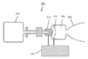
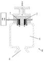
도 1은 일례에 따른 중심 전극 인젝터 시스템을 나타낸다.
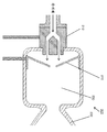
도 2a 내지 도 2c는 다른 예에 따른 스플래시 판(splash plate)을 갖는 중심 전극 인젝터 시스템을 나타낸다.
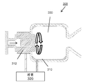
도 3a 및 도 3b는 다른 예에 따른 원형 전극을 갖는 중심 전극 인젝터 시스템을 나타낸다.
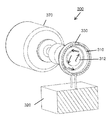
도 4는 다른 예에 따른 반대로 대전된 추진제 스트림을 갖는 중심 전극 인젝터 시스템을 나타낸다.
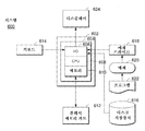
도 5는 본원에 기재된 예시적인 전극 인젝터 및 로켓 엔진 시스템과 함께 또는 연계되어 사용될 수 있는 예시적인 컴퓨터 시스템을 나타낸다.BRIEF DESCRIPTION OF THE DRAWINGS The non-limiting and non-exhaustive embodiments of the present invention are described with reference to the following drawings, wherein like reference numerals designate like parts throughout the various views unless otherwise indicated.
1 shows a center electrode injector system according to an example.
Figures 2A-2C illustrate a center electrode injector system with a splash plate according to another example.
Figures 3a and 3b show a center electrode injector system with a circular electrode according to another example.
Figure 4 shows a center electrode injector system with an oppositely charged propellant stream according to another example.
5 illustrates an exemplary computer system that may be used in conjunction with or in conjunction with the exemplary electrode injector and rocket engine systems described herein.
상세한 설명은 통상의 기술자가 다양한 실시형태들을 제조 및 사용할 수 있게 하기 위해 제시되어 있다. 특정한 장치, 기술 및 적용에 대한 설명은 단지 예로서 제공된다. 여기서 설명된 예에 대한 다양한 변형을 통상의 기술자는 쉽게 알 수 있을 것이며, 여기서 정의된 일반 원리는 본 기술의 사상 및 범위 내에서 다른 예들 및 용례들에 적용될 수 있다. 따라서, 개시된 기술은 본원에서 설명되고 도시된 예들로 제한되는 것이 아니고 청구항과 일치하는 범위를 부여 받는다.The detailed description is presented to enable a person skilled in the art to make and use various embodiments. The description of specific devices, techniques, and applications is provided by way of example only. Various modifications to the examples described herein will be readily apparent to those skilled in the art, and the generic principles defined herein may be applied to other examples and applications within the spirit and scope of the technology. Accordingly, the disclosed techniques are not limited to the examples described and illustrated herein, but are to be accorded the scope consistent with the claims.
본 발명의 일 양태에 따르면, 시스템 및 프로세스는 재생-냉각 구성요소 설계를 갖거나 갖지 않는 경량 엔진에 있어서의, 초전성 추진제, 특히 전기-제어식 점화 및/또는 전기-보조식 연소, 디지털 제어(점화 및/또는 스로틀링) 추진제를 사용하여 설명된다. 실시형태들 및 예들은 이원 추진제 엔진 설계(예를 들어, 개별 연료 및 산화제) 또는 일원 추진제(예를 들어, 구성적으로 최적화된 것) 로켓 엔진, 또는 이들의 조합을 포함할 수 있으며, 이들은 모두 전기적으로 제어가능한 시동 및 정지의 초전성 추진제 특성의 사용에 의한 별개의 그리고 신규한 이점을 가지며, 이 추진제는 부가적으로는 스로틀링되는 조정가능 추력을 산출하도록 유동 제어 또는 가변 전력에 의해 제어된다.According to one aspect of the present invention, systems and processes are used to produce supercharged propellants, particularly electrically-controlled ignition and / or electric-assisted combustion, digital control Ignition and / or throttling) propellants. Embodiments and examples may include a binary propellant engine design (e.g., individual fuel and oxidizer) or a single propellant (e.g., a structurally optimized) rocket engine, or a combination thereof, Has the distinct and novel advantage of using electrically controlled starting and stopping supercharged propellant properties which are additionally controlled by flow control or variable power to produce an adjustable thrust to be throttled .
도 1 내지 도 4를 참고하면, 초전성 일원 추진제 또는 이원 추진제를 사용하는 전기 스로틀링가능 엔진에 대한 상이한 배치 모드가 도시되어 있다. 일원 추진제로서, 예를 들어 가변 오리피스를 통한 유량 또는 압력의 다양한 조건하에서 바람직하지 않은 혼합비(MR) 변화를 받지 않는 단일 배합물이 상기 예에서 사용될 수 있다. 이원 추진제로서, 연료 또는 산화제 성분의 개별 첨가를 통해 일원 추진제 배합물에 의해 제공될 수 있는 것보다 더 높은 성능을 달성하도록 맞춰진, 하지만 최상의 성능에 대해서는 혼합비 최적조건에 의해 한정되는, 전기 연료 추진제 또는 전기 산화제 추진제의 개별 스트림이 전기적으로 점화가능한 및 스로틀링가능한 거동을 이용할 수 있다.Referring to Figures 1-4, different deployment modes for an electric throttling capable engine using a supercharged propellant or binary propellant are shown. As a single propellant, for example, a single combination that is not subject to undesirable mixing ratio (MR) changes under various conditions of flow rate or pressure through a variable orifice may be used in the example. As a binary propellant, an electric fuel propellant or electricity, which is tailored to achieve higher performance than can be provided by a single propellant combination through the individual addition of a fuel or oxidizer component, An individual stream of oxidant propellant can utilize electrically ignitable and throttling possible behavior.
초전성 추진제를 이용한 이원 추진제 또는 일원 추진제 로켓 엔진의 용례는 양자 모두 신규한 특징으로서 엔진의 시동 및 정지를 또한 제어하는 전기-제어식 인젝터를 갖는다. 부가적으로, 연소 챔버와 같은 재생-냉각 열 교환기 구성요소를 포함하는 설계 특징은, 비록 감소된 중량이기는 하지만 최상의 성능을 위해 고비용, 고온이 될 수 있는 초합금을 필요로 하는 비냉각식 또는 복사 냉각식 설계에 비해 강인하고 전통적인 구성 재료의 사용을 가능하게 한다. 간단한 인젝터 전극들이, 특히 전극 인젝터를 통한 추진제(들)의 질량 유량 제어와 연계될 때, 연소 압력 및 그에 따라 엔진의 추력을 변화시키도록 전기적으로 제어될 수 있다. 대등하거나 더 양호한 성능 가능성으로 히드라진 같은 유독성 대안을 대체할 수 있는 이들 고-성능 초전성 추진제가 또한 제공하는 높은 연소 온도를 능동적으로 활용하는 강인한 재생-냉각 엔진 구성요소에 대한 선택과 함께, 초전성 추진제에 의해 제공되는 감소된 유해성, 감소된 유독성 및 전기 제어성의 장점을 동시에 제공함으로써, 결과적인 스로틀기능은 단순한 구성요소 및 재료로 현 기술 상태를 진전시킨다. 액체 추진제가 연소 챔버에 진입하기 전에 "부분적으로" 활성화된 전극들을 거처, 통해, 또는 지나서 유동할 때의 액체 추진제의 체류 시간은 사전조정될 수 있고/부분적으로 대처될 수 있다.The use of a binary propellant or a single propellant rocket engine with a supercharged propellant both have an electro-controlled injector that also controls the starting and stopping of the engine as a novel feature. Additionally, design features that include regeneration-cooling heat exchanger components, such as combustion chambers, can be used for non-cooled or radiant cooling applications requiring a superalloy that can be expensive, high temperature for best performance, Making it possible to use more robust and conventional constituent materials than the conventional design. When simple injector electrodes are associated with mass flow control of the propellant (s), particularly through the electrode injector, they can be electronically controlled to change the combustion pressure and hence the thrust of the engine. These high-performance superpower propellants, which can replace toxic alternatives such as hydrazine with comparable or better performance possibilities, also offer a choice of tough regeneration-cooling engine components that actively take advantage of the high combustion temperatures offered, By simultaneously providing the advantages of reduced hazard, reduced toxicity and electrical control provided by the propellant, the resulting throttle function advances the state of the art to simple components and materials. The residence time of the liquid propellant when the liquid propellant flows through, through, or past "partially" activated electrodes before entering the combustion chamber can be preconditioned and / or partially counteracted.
소정 양태에서, 일원 추진제 엔진은, 높은 재료 또는 제조 비용, 압력 강하, 감소된 수명, 및 제한된 온-오프 듀티 사이클을 갖는 미립자 팩 촉매 섹션 또는 촉매 활성 연소 챔버를 제거하는, 캐소드(전통적으로 음으로 대전됨) 또는 애노드(양으로 대전됨) 구조의 양자 모두를 갖는 전기-제어식 인젝터의 사용에 의해 향상된다. 따라서, 일원 추진제 엔진에 대한 간단한 설계는, 전기 제어식 인젝터 그리드에 의한 초전성 추진제의 사용에 의해 가능하지 않은 경우 온도 요건을 충족시키는데 요구되는 고비용 재료의 사용을 완화시키는 특징부로서 재생-냉각 챔버를 채용할 수 있다. 경량 설계에서는, 의도된 용례에 대한 비용 대 성능의 타협 상 하나가 나머지 엔진 개념에 비해 유리한 것으로 판명될 수 있기 때문에, 재생-냉각 특징부는 필요하지 않을 수 있다.In certain embodiments, the unitary propellant engine may include a particulate pack catalyst section or catalytic active combustion chamber having a high material or manufacturing cost, a pressure drop, a reduced lifetime, and a limited on-off duty cycle, Controlled injector having both an anode (charged) and an anode (positively charged) structure. Thus, a simple design for a unitary propellant engine is a feature that alleviates the use of high cost materials required to meet temperature requirements if not possible by the use of a superplastic propellant by an electrically controlled injector grid, Can be adopted. In a lightweight design, the regeneration-cooling feature may not be needed, since one compromise in cost vs. performance for the intended application may prove advantageous over the rest of the engine concept.
부가적으로, 일부 예에서, 단일 설계 재생-냉각 엔진은 로켓 엔진 또는 비행 운송수단의 임무 시에 상당히 팽창할 수 있는 일원 추진제 또는 이원 추진제를 채용할 수 있다. 따라서, 듀티 사이클은, 인젝터로서 조합된 캐소드/애노드 구조의 하나 또는 다수의 요소로서 공통의 전기-제어식 인젝터 그리드를 사용하여 종래의 밸브 및 질량 유동 제어기에 의해 제어될 수 있는 일원 추진제 모드 또는 이원 추진제 모드를 포함할 수 있다. 따라서, 온-오프 듀티 사이클 또는 추력 조정성을 제공하기 위한 일원 추진제 또는 이원 추진제 초전성 추진제의 유연성은 운송수단에 가용한 추진제의 부피에 의해서만 제한된다.Additionally, in some instances, a single design regeneration-cooling engine may employ a single propellant or binary propellant that can expand considerably during the mission of the rocket engine or flight vehicle. Thus, the duty cycle can be controlled by a single valve or mass flow controller using a common electro-controlled injector grid as one or more elements of the combined cathode / anode structure as injector, Mode. Thus, the flexibility of a single propellant or binary propellant superplasticizer to provide an on-off duty cycle or thrust adjustability is limited only by the volume of propellant available to the vehicle.
도 1은 일례에 따른 중심 전극 인젝터 시스템(100)을 나타낸다. 이 예에서, 하나의 전하를 갖는 중심 전극(110)의 단부 또는 팁에서 점화되는 초전성 일원 추진제는 유동 제어 및 전력 변화를 통해 스로틀링되며, 반대측 전하는 외측 전극 본체(112)에 배치된다. 추진제는 일반적으로 절연체(114)에 의해 부분적으로 절연되는 중심 전극(110)을 포함하는 점화 영역(116)을 통해 그리고 인젝터 본체(112)를 통해 연료 탱크(170)로부터 유동한다. 전기적으로 점화가능한 추진제가 인젝터 본체(112)를 통해 유동할 때, 전원(102)으로부터의 전력이 중심 전극(110) 및 인젝터 본체(112)를 거쳐서 공급되며, 연소 챔버(130)에서 연소가 발생하고 노즐(132)을 통해 방출된다. 시스템(100)은, 전극 인젝터 시스템(100)과 함께 또는 떨어져서 위치될 수 있는 제어기(160)에 의해 동적으로 제어될 수 있는, 전극(110, 112)에 공급되는 전력의 양 및/또는 초전성 추진제의 유동 제어에 의해 스로틀링될 수 있다.1 shows a central
이하에서 더 상세하게 설명되는 바와 같이, 본원에서 설명되는 예시적인 전극 인젝터 시스템은 하나 이상의 전기적으로 점화가능한 추진제, 즉 그것을 통한 전력에 의해 점화 및/또는 유지되는 추진제를 사용할 수 있다. 이러한 추진제가 예를 들어 미국 특허 출원 번호 7,958,823 및 8,317,953, 및 미국 공보 번호 2011/0259230(시리얼 번호 12/989,639) 및 2011/0067789(시리얼 번호 12/993,084)에 설명되어 있으며, 이들은 제어가능한 로켓 엔진에 있어서의 이들 신규한 출원에서 일원 추진제 또는 이원 추진제 액체 또는 겔에 대해 공통될 수 있는 고체 또는 플라스티솔 추진제 성분의 사용에 관한 것이다. 이들 참고물은 모든 목적을 위해 그 전체가 참조로 통합된다.As will be described in more detail below, the exemplary electrode injector system described herein may use one or more electrically ignitable propellants, i.e., propellants that are ignited and / or held by power through it. Such propellants are described, for example, in U.S. Patent Application Nos. 7,958,823 and 8,317,953, and U.S. Publication No. 2011/0259230 (Serial Number 12 / 989,639) and 2011/0067789 (Serial Number 12 / 993,084) The present invention relates to the use of solid or plastisol propellant components that can be common to a single propellant or binary propellant liquid or gel in these new applications. These references are incorporated by reference in their entirety for all purposes.
도 2a 내지 도 2c는 다른 예에 따른 중심 전극 인젝터 시스템(200)을 나타낸다. 특히, 도 2a는 전극 인젝터 시스템(200)의 사시도를 나타내고, 도 2b는 내부의 스플래시 판 점화 배치를 노출시키는 시스템(200)의 단면도를 나타내며, 도 2c는 시스템(200)의 스플래시 판 점화 시스템을 더 상세하게 나타낸다.2A-2C show a central
이 예에서, 연소 챔버(230)의 구성요소로서 고정된 스플래시 판(210)과 충돌시에 점화되는 초전성 일원 추진제 또는 이원 추진제는 유동 제어 및 전력 변화를 통해 스로틀링된다. 다른 예에서, 스플래시 판(210)은 외측 또는 연소 챔버(230), 예를 들어 인젝터 본체(212)의 원위 단부에 위치조정될 수 있다. 이 예에서, 연료 탱크(201)로부터의 초전성 추진제 스트림(들)은, 그들이 전원(220)을 통해 인젝터 본체(212)를 통과함에 따라 전하가 주어지게 되고, 연소 챔버 스플래시 판(210)에 배치된 반대 전하는 추진제의 점화 및 연소를 발생시킨다. 도 2b에 더 명확하게 도시된 바와 같이, 추진제는 전하를 제공받고 인젝터 본체(212)를 통해 유동하여 반대로 대전된 스플래시 판(210)에 충돌한다. 대전된 추진제는 스플래시 판(210)과 접촉할 때 점화되고 연소 챔버(230) 내에서 가스 생성물로 연소되며 노즐(232)로 배출되어 추력을 제공한다. 이전의 예와 마찬가지로, 제어기(본원에는 도시되지 않음)는 시스템에 제공된 전하 및/또는 추진제의 유동을 제어하기 위해 사용될 수 있어, 시스템의 추력의 제어를 제공한다.In this example, the supercharged one propellant or binary propellant that is ignited in collision with the
스플래시 판은, 추진제가 반대로 대전된 그리드, 판, 또는 다른 특징부와 접촉하게 하여 전기 제어 및/또는 유량을 통한 점화 및 조절을 가능하게 하는 설계 특징부를 포함하는 개념의 일례로서 제공된다. 대전된 설계 특징부의 보다 상류의 위치는 엔진의 성능을 최적화 하기 위해 원하는 바에 따라 점화의 임계치까지 추진제를 점진적으로 고감도화 하기 위해 사용될 수 있으며-엔진 동작의 효율 및 응답 시간을 증가시키기 위해서 필요에 따라 추가적인 하류 대전된 표면이 사용된다.The splash plate is provided as an example of a concept that includes a design feature that allows the propellant to contact an oppositely charged grid, plate, or other feature to enable ignition and control through electrical control and / or flow rate. The more upstream position of the charged design features may be used to gradually sensitize the propellant to the threshold of ignition as desired to optimize the performance of the engine and to increase the efficiency and response time of the engine operation as needed An additional downstream charged surface is used.
도 3a 및 도 3b는, 전원(320)에 의해 반대 전하가 제공되는 인젝터 본체(312)와 원형 전극(310)과의 사이의 소용돌이 전극 구성의 단면도 및 사시도를 포함하는 다른 예에 따른 중심 전극 인젝터 시스템(300)을 나타낸다. 이 예에서, 이 경우에는 원형 전극(310)과 충돌시에 점화되는, 탱크(370)로부터의 초전성 일원 추진제 또는 이원 추진제는, 유동 제어 및 전력 변화를 통해 스로틀링되며, 추진제(들)은 원형 유동을 형성하도록 인젝터 본체(312)에 의해 주입된다. 특히, 인젝터 본체(312)는 내부에서 대체적 원형 유동을 갖도록 연소 챔버(330) 안으로 추진제를 주입하도록 형성된다. 제2 원형 전극(310)은 연소 챔버의 내측 벽 주위에 위치설정되어 접촉시에 추진제의 연소를 유발한다. 본 실시예, 그리고, 연소 챔버(330) 내의 원형 유동의 장점은 연소 챔버(330)(및 따라서 엔진)의 보다 짧은 전체적인 길이 및 비교적 높은 연소 효율을 포함한다.3A and 3B are a cross-sectional view and a perspective view of a swirled electrode configuration between the
도 4는 다른 예에 따른 중심 전극 인젝터 시스템(400)을 나타낸다. 이 예에서, 반대로 대전된 추진제 스트림과 충돌 시에 점화되는 초전성 추진제는 유동 제어 및 전력 변화를 통해 스로틀링된다. 예를 들어, 추진제는, 전원(420)에 의해 대전되는 인젝터 본체(410 및 412)를 통과하면서, 반대로 대전된 챔버(430)의 전방부에서 점화되고 연소된다. 노즐(432)에서 배출되는 고온의 연소 생성물이 추력을 제공한다. 연속적인 추진제 스트림에는 반대 전하가 주어져서 점화를 제공한다.4 shows a central
도 1 내지 도 4에 나타낸 바와 같은 상이한 실시형태는 이하에서 일반적으로 논의되는 바와 같은 다양한 이점 및 성능 특성을 제공한다. 본원의 설명과 일치하는 다른 변화 및 변형이 가능하며 고려된다는 것이 통상의 기술자에 의해 이해될 것이다. 또한, 위에서 논의된 다양한 실시형태는 다수의 상이한 모드에서 동작될 수 있다. 일부 예에서, 이원 추진제 모드는 엔진 시스템에서 개별 연료 및 산화제를 사용하는 것을 포함한다. 이원 추진제 모드는 일반적으로, 일원 추진제 모드에 비해, 인젝터를 단순화시키고(예를 들어, 일반적으로 독특한 인젝터 분사 패턴을 위한 제조 비용을 낮춘다), '친환경적인' 감소된 유독성을 갖는 초전성 추진제(예를 들어, 알킬히드라진 연료 군, 또는 유독성이 두드러지는 산화제의 질소 산화물 군에서 현재 사용되는 추진제에 비교됨)의 사용에 의한 스로틀링성 및 정지-시동, 더 높은 성능, 충격, 마찰, 또는 정전기 민감성과 같은 감소된 취급 위험, 단순성을 위한 재생-냉각 설계의 지속 사용, 및 감소된 비용을 제공한다.The different embodiments as shown in Figures 1 to 4 provide various advantages and performance characteristics as generally discussed below. It will be understood by those of ordinary skill in the art that other changes and modifications consistent with the description herein are possible and contemplated. In addition, the various embodiments discussed above may be operated in a number of different modes. In some instances, the binary propellant mode includes the use of individual fuels and oxidants in the engine system. The binary propellant mode generally reduces the injector's propellant (eg, generally lowering the manufacturing cost for a unique injector injection pattern) compared to the one propellant mode, a 'propellant' propellant with reduced 'toxicity' Such as throttleability and stop-start, higher performance, impact, friction, or electrostatic susceptibility by use of alkyl hydrazine fuel groups, or propellants presently used in nitrogen oxides groups of oxidizing agents that are prominent toxicants Reduced handling risk, continued use of regeneration-cooling designs for simplicity, and reduced costs.
다른 예에서, 일원 추진제 모드는 구성적으로 최적화된 추진제를 사용하는 것을 포함한다. 일원 추진제 모드는, 신규한 재생 냉각 능력을 제공하는 위와 같은 특징을 갖는 더 높은 성능 추진제를 채용할 때, 고온 초합금(예를 들어, 하스텔로이, 화스팔로이, 또는 인코넬군 재료)에 대한 필요성을 감소시키거나 제거할 수 있다. 일원 추진제 모드는 또한, 압력 강하, 촉매 성능 저하(예를 들어 소결), 고비용, 엄격한 제조 요건, 제한된 듀티 사이클, 추가된 중량, 제한된 스로틀링성, 비효율적인 연소 등을 고려할 때 사용 수명을 감소시키는, 연소 챔버 내의 촉매 또는 별도의 촉매 팩 섹션에 대한 필요성을 감소시킬 수 있다.In another example, the one propellant mode includes using a propellant that is structurally optimized. The single propellant mode reduces the need for a high temperature superalloy (e.g., Hastelloy, Hass Paloi, or Inconel family materials) when employing a higher performance propellant having the above characteristics to provide a novel regenerative cooling capacity. Or removed. The single propellant mode also reduces the service life in view of pressure drop, catalyst degradation (e.g., sintering), high cost, stringent manufacturing requirements, limited duty cycle, added weight, limited throttling, inefficient combustion, The need for a catalyst in the combustion chamber or a separate catalyst pack section can be reduced.
부가적으로, 다른 예에서, "다원 또는 삼원 추진제" 모드가 사용될 수 있다. 일반적인 재생-냉각 설계에서, 전기-제어식 전극 그리드 인젝터는 인젝터 그리드에 대한 유동 제어 및 전기 제어와 조합될 때 스로틀링성을 확대시킬 수 있는 일원 추진제 또는 이원 추진제 유동의 연속적인 변화에서 기능할 수 있다.Additionally, in another example, a "multiple or triple propellant" mode may be used. In a typical regeneration-cooling design, the electro-controlled electrode grid injector can function in a continuous change of a single propellant or binary propellant flow that can expand throttling capability when combined with flow control and electrical control for the injector grid.
가스 발생기 모드: 일원 추진제 분해 가스 출력은, 유체를 운반하는 작업을 하는 이러한 설계를 갖는 그 밖의 운송수단에서 가압을 제공하고, 전체적인 임무의 이점에 대해 이러한 작업을 하는 밸브 또는 이동가능 구성요소를 가동하기 위해 관리될 수 있다. 예를 들어, 로켓 추진을 위한 고온의 고속 플럭스 최적조건 대신에 가스 종의 맞춤 출력이 요구되는 경우, 추진 운동을 위한 추력을 제공하는 것이 아니라, 추진 요소가 또한 위치될 수 있는 항공기의 다양한 임무를 실행하도록 가압 가스를 제공하기 위해 이러한 동일한 개념이 채용될 수 있다.Gas generator mode: A single propellant decomposition gas output provides pressurization in other modes of transport with this design to carry fluid, and actuates valves or movable components that do this work for the benefit of the overall mission Lt; / RTI > For example, if a customized output of a gas species is required instead of a high-temperature, high-speed flux optimum for rocket propulsion, rather than providing thrust for propulsion, the various tasks of the aircraft This same concept can be employed to provide pressurized gas to perform.
추가적인 연소 효율은, 챔버가 이러한 개념의 사용에 최적화될 때, 일반적인 재생 엔진 설계 또는 복사 냉각식 설계에서 불활성 중량을 더 감소시키고, 추력을 증가시키고, 스로틀링성을 확대시키며 임무 유용을 확대시키는 결과를 가져올 수 있다.Additional combustion efficiencies may result in further reductions in inert weight, thrust, throttling, and widening of duty utilization in a typical regenerative engine design or radiative cooling design when the chamber is optimized for use with this concept Can be imported.
본원의 설명된 실시형태의 양태는 통상의 기술자에게 쉽게 이해되지 않는 종래의 일원 추진제 및 이원 추진제 로켓 엔진의 양자 모두에 대한 주요 결점을 극복한다. 감소된 제조 비용, 재생 설계, 또는 대안적으로는 복사 냉각식 엔진 설계, 촉매 제거, 성능 향상, 유독성 및 위험 감소의 조합된 특징은 중요하며 - 시연 단계 활동에 용이하게 그리고 즉시 적용가능하다. 이원 추진제 또는 일원 추진제와 같은 이러한 전기 제어식 액체 추진제의 다-상(multi-phase) 성능은 배치될 때 임무 유효성을 크게 향상시킬 수 있는 넓은 범위의 배치 선택지를 포함한다.The aspects of the described embodiments of the present invention overcome the major drawbacks of both conventional single propellant and binary propellant rocket engines that are not easily understood by the ordinary artisan. Reduced manufacturing costs, regenerative designs, or alternatively, combined features of radiative cooling engine design, catalyst removal, performance enhancement, toxicity and risk reduction are important - and are readily and readily applicable to demonstration phase activities. The multi-phase performance of such electrically controlled liquid propellants, such as binary propellants or one propellant, includes a wide range of placement options that can significantly improve mission effectiveness when deployed.
이들 예시적인 신규한 용례들은 공간 및 방어 임무의 양자 모두에 이익을 주며 일반적으로 화학적인 추진 기술에 대한 용례를 가질 수 있다. 용례들은, 그들의 고온의 급속한 폭연 및 가스 발생을 통해 작업을 하기 위한 에너지학을 제공하기 위해 또는 조율가능한 액체 폭발로서, 특히 유전, 광업의 표면하 에너지학 용도 또는 해저 용례에서의 상업적인 활동에서도 존재한다.These exemplary novel applications benefit both space and defense missions and can generally be used for chemical propulsion techniques. The applications exist also in the field of energy exploitation, especially in oil fields, underground energy applications in mining or underground applications, to provide energy for working through their high-temperature rapid detonation and gas evolution .
도 5는 예를 들어 예시적인 엔진으로 가는 연료 및/또는 전력을 제어 및 스로틀링하는 것에 관한 상기 프로세스들 중 어느 하나를 실행하도록 구성된 예시적인 컴퓨팅 시스템(600)을 도시한다. 또한, 예시적인 컴퓨팅 시스템은 로켓 엔진, 로켓 엔진을 포함하는 운송수단, 또는 로켓 엔진과 통신하고 그리고/또는 로켓 엔진을 제어하도록 작동할 수 있는 주변 장치에 전체적으로 또는 부분적으로 포함될 수 있다. 이와 관련하여, 컴퓨팅 시스템(600)은 예를 들어, 프로세서, 메모리, 저장장치, 및 입력/출력 장치 (예를 들어, 모니터, 키보드, 디스크 드라이브, 인터넷 연결부 등)을 포함할 수 있다. 그러나, 컴퓨팅 시스템(600)은 프로세스들의 양태 중 일부 또는 모두를 수행하기 위한 회로 또는 다른 특화된 하드웨어를 포함할 수 있다. 일부 작동 설정 환경에서, 컴퓨팅 시스템(600)은, 각각이 소프트웨어, 하드웨어, 또는 그의 일부 조합에서 프로세스 중 일부 양태를 수행하도록 구성된 하나 이상의 유닛을 포함하는 시스템으로서 구성될 수 있다.FIG. 5 illustrates an
도 5는 위에서 설명된 프로세스를 실행하는 데 사용될 수 있는 다수의 구성요소를 포함하는 컴퓨팅 시스템(600)을 도시한다. 메인 시스템(602)은 입력/출력 ("I/O") 섹션(606), 하나 이상의 중앙 처리 유닛("CPU")(608), 및 그에 관련된 플래시 메모리 카드(612)를 가질 수 있는 메모리 섹션(610)을 갖는 마더보드(604)를 포함한다. I/O 섹션(606)은 디스플레이(624), 키보드(614), 디스크 저장 유닛(616), 및 매체 드라이브 유닛(618)에 연결되어 있다. 매체 드라이브 유닛(618)은 프로그램(622) 및/또는 데이터를 포함할 수 있는 컴퓨터 판독가능 매체(620)를 판독/기록할 수 있다. FIG. 5 illustrates a
위에서 설명된 프로세스들의 결과들에 기초한 적어도 일부 값들이 차후의 사용을 위해 저장될 수 있다. 부가적으로, 위에서 설명된 프로세스들 중 임의의 것을 컴퓨터를 사용하여 수행하기 위한 하나 이상의 컴퓨터 프로그램들을 저장(예컨대, 유형적으로 구현)하기 위해 비일시적 컴퓨터 판독가능 매체가 사용될 수 있다. 컴퓨터 프로그램은 예를 들어, 범용 프로그래밍 언어 (예컨대, 파스칼, C, C++, 자바) 또는 일부 특화된 특정 응용 언어로 기록될 수 있다.At least some values based on the results of the processes described above may be stored for future use. Additionally, non-transitory computer readable media may be used to store (e.g., tangibly embody) one or more computer programs for carrying out any of the processes described above using a computer. A computer program may be written in, for example, a general purpose programming language (e.g., Pascal, C, C ++, Java) or some specialized specialized application language.
다양한 예시적인 실시형태들이 본원에 기재되어 있다. 이 예들이 비제한적인 의미로 언급되어 있다. 이 예들은 개시된 기술의 보다 광범위하게 적용가능한 양태들을 예시하기 위해 제공되어 있다. 다양한 실시형태들의 진정한 사상 및 범위 내에서 다양한 변경들이 이루어질 수 있고 등가물들로 대체될 수 있다. 또한, 특정의 상황, 재료, 물질 조성, 프로세스, 프로세스 동작(들) 또는 단계(들)를 다양한 실시형태들의 목적(들), 사상 또는 범위에 적합하도록 하기 위해 많은 수정들이 행해질 수 있다. 게다가, 통상의 기술자라면 인식할 것인 바와 같이, 본원에 기재되고 예시된 개개의 변형들 각각은, 다양한 실시형태들의 범위 또는 사상 내에서 다른 몇몇 실시형태들 중 임의의 것의 특징들로부터 용이하게 분리되거나 그 특징들과 결합될 수 있는 개별 구성요소들 및 특징들을 갖는다. 이러한 수정들 전부는 본 개시 내용과 연관된 청구항들의 범위 내에 있는 것으로 의도된다.Various exemplary embodiments are described herein. These examples are mentioned in a non-limiting sense. These examples are provided to illustrate more broadly applicable aspects of the disclosed technique. Various modifications may be made and equivalents may be substituted within the true spirit and scope of the various embodiments. In addition, many modifications may be made to adapt a particular situation, material, composition of matter, process, process (s) or step (s) to the object (s), idea, or scope of the various embodiments. In addition, it will be appreciated by those of ordinary skill in the art that each of the individual variations described and illustrated herein can be readily decoupled from features of any of several other embodiments within the scope or spirit of the various embodiments. Or individual features and features that can be combined with those features. All such modifications are intended to be within the scope of the claims relating to this disclosure.
본 발명의 앞서 기재된 설명은 통상의 기술자가 그의 최상의 모드인 것으로 현재 고려되는 것을 제조 및 사용하게 할 수 있을지라도, 통상의 기술자들은 본원에서 특정 실시형태, 방법, 및 예들의 변형들, 조합들, 및 등가물들의 존재를 이해 및 인식할 것이다. 그러므로, 본 발명은 전술한 실시형태, 방법, 및 예들에 의해 제한되어서는 안되며 본 발명의 사상 및 범위 내에서 모든 실시형태 및 방법에 의해 이루어진다.Although the foregoing description of the invention allows one of ordinary skill in the art to make and use what is currently considered to be its best mode, it will be appreciated by those of ordinary skill in the art that variations, combinations, And equivalents thereof. Therefore, the present invention should not be limited by the above-described embodiments, methods, and examples, but is made by all embodiments and methods within the spirit and scope of the present invention.
Claims (20)
전기적으로 점화가능한 추진제를 공급하기 위한 인젝터 본체,
연소 챔버, 및
전극들로서, 제1 전극은 인젝터 본체에 포함되고, 제2 전극은 전기적으로 점화가능한 추진제의 점화를 유발하도록 제1 전극에 대해 위치설정되는, 전극들을 포함하는, 장치.An apparatus for electrically igniting and throttling a superplastic propellant, the apparatus comprising:
An injector body for supplying an electrically ignitable propellant,
Combustion chamber, and
Wherein the first electrode is contained in the injector body and the second electrode is positioned relative to the first electrode to cause ignition of the electrically ignitable propellant.
전기적으로 점화가능한 추진제를 전극에 인접하여 유동하도록 주입하는 단계, 및
전기적으로 점화가능한 추진제가 전극에 인접하여 지나갈 때 전기적으로 점화가능한 추진제를 점화시키도록 전극에 전력을 선택적으로 제공하는 단계를 포함하는, 방법.A method for electrically igniting and throttling a supercharging propellant, the method comprising:
Injecting an electrically ignitable propellant to flow adjacent to the electrode, and
Selectively providing electrical power to the electrode to ignite an electrically ignitable propellant when the electrically ignitable propellant passes adjacent the electrode.
Applications Claiming Priority (3)
| Application Number | Priority Date | Filing Date | Title |
|---|---|---|---|
| US201361871767P | 2013-08-29 | 2013-08-29 | |
| US61/871,767 | 2013-08-29 | ||
| PCT/US2014/053528 WO2015031825A1 (en) | 2013-08-29 | 2014-08-29 | Electrically ignited and throttled pyroelectric propellant rocket engine |
Publications (1)
| Publication Number | Publication Date |
|---|---|
| KR20160055169A true KR20160055169A (en) | 2016-05-17 |
Family
ID=52581231
Family Applications (1)
| Application Number | Title | Priority Date | Filing Date |
|---|---|---|---|
| KR1020167008182A KR20160055169A (en) | 2013-08-29 | 2014-08-29 | Electrically ignited and throttled pyroelectric propellant rocket engine |
Country Status (5)
| Country | Link |
|---|---|
| US (1) | US20150059314A1 (en) |
| EP (1) | EP3039277A4 (en) |
| JP (1) | JP2016536520A (en) |
| KR (1) | KR20160055169A (en) |
| WO (1) | WO2015031825A1 (en) |
Families Citing this family (7)
| Publication number | Priority date | Publication date | Assignee | Title |
|---|---|---|---|---|
| US10532830B2 (en) * | 2016-06-09 | 2020-01-14 | The Boeing Company | Stackable pancake satellite |
| CN107044362B (en) * | 2016-12-07 | 2018-12-11 | 西安近代化学研究所 | A kind of low plumage flame feature engine |
| CN111502860B (en) * | 2020-04-30 | 2022-06-28 | 南京理工大学 | Pressure swirl injector with modular design |
| DE102020122337A1 (en) * | 2020-08-26 | 2022-03-03 | LabOrbital GmbH | Hot gas generating device with monergolic ionic fuel and low voltage ignition |
| CN112796907B (en) * | 2021-01-05 | 2021-12-14 | 南京理工大学 | Magnesium gel carbon dioxide engine |
| CN114592989B (en) * | 2022-05-09 | 2022-08-16 | 西安航天动力研究所 | Liquid oxygen kerosene pintle injector thrust chamber and starting method thereof |
| CN115263604A (en) * | 2022-06-22 | 2022-11-01 | 北京控制工程研究所 | Hole-aligning mutual-striking injector applied to light quick-response two-component engine |
Family Cites Families (15)
| Publication number | Priority date | Publication date | Assignee | Title |
|---|---|---|---|---|
| US3057149A (en) * | 1958-09-30 | 1962-10-09 | Aerojet General Co | Rocket propellant spark ignition system |
| US3790088A (en) * | 1967-08-29 | 1974-02-05 | Us Army | Propellant splash plate having flow directing means |
| US3651644A (en) * | 1969-06-25 | 1972-03-28 | Marshall Ind | Apparatus for initiating decomposition of an exothermic propellant |
| FR2497273B1 (en) * | 1980-12-29 | 1985-09-20 | Onera (Off Nat Aerospatiale) | METHOD AND DEVICE FOR IGNITION OF A FUEL MIXTURE |
| US5395076A (en) * | 1993-03-19 | 1995-03-07 | Martin Marietta Corporation | Spacecraft velocity change maneuvers by variable arcjets |
| US6469424B1 (en) * | 1998-12-14 | 2002-10-22 | United Technologies Corporation | Ignitor for liquid fuel rocket engines |
| WO2008060255A2 (en) * | 2002-01-16 | 2008-05-22 | W.E. Research, Llc | Electrically controlled extinguishable solid propellant motors |
| US6931832B2 (en) * | 2003-05-13 | 2005-08-23 | United Technologies Corporation | Monopropellant combustion system |
| US7246483B2 (en) * | 2004-07-21 | 2007-07-24 | United Technologies Corporation | Energetic detonation propulsion |
| US8337765B2 (en) * | 2005-08-26 | 2012-12-25 | Honeywell International Inc. | Electrocatalytically induced propellant decomposition |
| US7634903B2 (en) * | 2005-10-12 | 2009-12-22 | Richard Cary Phillips | Ion impulse engine |
| US8122703B2 (en) * | 2006-04-28 | 2012-02-28 | United Technologies Corporation | Coaxial ignition assembly |
| JP5154568B2 (en) * | 2006-12-04 | 2013-02-27 | ファイアースター エンジニアリング,エルエルシー | Spark-integrated propellant injector head with flashback barrier |
| FR2914369B1 (en) * | 2007-03-30 | 2014-02-07 | Snecma | ELECTROLYTIC IGNITER FOR ENGINE-ROCKET IN MONERGOL |
| WO2009140635A1 (en) * | 2008-05-16 | 2009-11-19 | Digital Solid State Propulsion Llc | Electrode ignition and control of electrically ignitable materials |
-
2014
- 2014-08-29 JP JP2016537912A patent/JP2016536520A/en active Pending
- 2014-08-29 KR KR1020167008182A patent/KR20160055169A/en not_active Application Discontinuation
- 2014-08-29 US US14/473,708 patent/US20150059314A1/en not_active Abandoned
- 2014-08-29 WO PCT/US2014/053528 patent/WO2015031825A1/en active Application Filing
- 2014-08-29 EP EP14839965.2A patent/EP3039277A4/en not_active Withdrawn
Also Published As
| Publication number | Publication date |
|---|---|
| JP2016536520A (en) | 2016-11-24 |
| EP3039277A4 (en) | 2017-04-26 |
| US20150059314A1 (en) | 2015-03-05 |
| WO2015031825A1 (en) | 2015-03-05 |
| EP3039277A1 (en) | 2016-07-06 |
Similar Documents
| Publication | Publication Date | Title |
|---|---|---|
| KR20160055169A (en) | Electrically ignited and throttled pyroelectric propellant rocket engine | |
| JP4113333B2 (en) | Rocket motor assembly | |
| CN109595100B (en) | Electric ignition green unit liquid rocket engine structure | |
| US7506500B1 (en) | Propulsion from combustion of solid propellant pellet-projectiles | |
| US8776526B2 (en) | Motor with solid fuel installed within combustion chamber and vortex generator installed on inner wall of combustion chamber | |
| US7770380B2 (en) | Methods of controlling solid propellant ignition, combustion, and extinguishment | |
| US20130139487A1 (en) | Variable initiation location system for pulse detonation combustor | |
| US7788900B2 (en) | Electrically controlled extinguishable solid propellant motors | |
| JP2007192221A (en) | Acoustic cavity manifold for rocket engine, rocket engine, and method for improving efficiency of specific impulse of rocket engine | |
| Venugopal et al. | Hybrid rocket technology | |
| US11408376B2 (en) | Thrust augmentation of an additively manufactured hybrid rocket system using secondary oxidizer injection | |
| US3143853A (en) | Solid propellant burn area control | |
| EP2600062A2 (en) | Variable initiation location system for pulse detonation combustor | |
| Tsay et al. | Development of Busek 0.5 N green monopropellant thruster | |
| Liu et al. | A long duration and high reliability liquid apogee engine for satellites | |
| US11480136B1 (en) | Monopropellant continuous detonation engines | |
| Heister et al. | Survey of rotating detonation wave combustor technology and potential rocket vehicle applications | |
| Pinto et al. | Green gelled propellant highly throtteable rocket motor and gas generator technology: status and application | |
| JP2022553637A (en) | Spacecraft hybrid propulsion system | |
| US11724829B2 (en) | Miniaturized green end-burning hybrid propulsion system for cubesats | |
| Kageyama et al. | Effect of Aft Chamber Volume on Hybrid Rocket Combustion Efficiency | |
| Scharlemann et al. | Development of propulsion means for microsatellites | |
| US20220315252A1 (en) | Miniaturized green end-burning hybrid propulsion system for cubesats | |
| JP2016044554A (en) | Flying object thruster | |
| Smith et al. | A Miniaturized Green End-Burning Hybrid Propulsion System for CubeSats |
Legal Events
| Date | Code | Title | Description |
|---|---|---|---|
| WITN | Application deemed withdrawn, e.g. because no request for examination was filed or no examination fee was paid |