KR20160052811A - Laser-marked polymer workpiece - Google Patents
Laser-marked polymer workpiece Download PDFInfo
- Publication number
- KR20160052811A KR20160052811A KR1020167011643A KR20167011643A KR20160052811A KR 20160052811 A KR20160052811 A KR 20160052811A KR 1020167011643 A KR1020167011643 A KR 1020167011643A KR 20167011643 A KR20167011643 A KR 20167011643A KR 20160052811 A KR20160052811 A KR 20160052811A
- Authority
- KR
- South Korea
- Prior art keywords
- laser
- opaque
- mark
- transparent
- polymeric
- Prior art date
Links
Images


Classifications
-
- B—PERFORMING OPERATIONS; TRANSPORTING
- B41—PRINTING; LINING MACHINES; TYPEWRITERS; STAMPS
- B41M—PRINTING, DUPLICATING, MARKING, OR COPYING PROCESSES; COLOUR PRINTING
- B41M5/00—Duplicating or marking methods; Sheet materials for use therein
- B41M5/26—Thermography ; Marking by high energetic means, e.g. laser otherwise than by burning, and characterised by the material used
- B41M5/267—Marking of plastic artifacts, e.g. with laser
-
- B—PERFORMING OPERATIONS; TRANSPORTING
- B29—WORKING OF PLASTICS; WORKING OF SUBSTANCES IN A PLASTIC STATE IN GENERAL
- B29C—SHAPING OR JOINING OF PLASTICS; SHAPING OF MATERIAL IN A PLASTIC STATE, NOT OTHERWISE PROVIDED FOR; AFTER-TREATMENT OF THE SHAPED PRODUCTS, e.g. REPAIRING
- B29C45/00—Injection moulding, i.e. forcing the required volume of moulding material through a nozzle into a closed mould; Apparatus therefor
- B29C45/14—Injection moulding, i.e. forcing the required volume of moulding material through a nozzle into a closed mould; Apparatus therefor incorporating preformed parts or layers, e.g. injection moulding around inserts or for coating articles
-
- B—PERFORMING OPERATIONS; TRANSPORTING
- B32—LAYERED PRODUCTS
- B32B—LAYERED PRODUCTS, i.e. PRODUCTS BUILT-UP OF STRATA OF FLAT OR NON-FLAT, e.g. CELLULAR OR HONEYCOMB, FORM
- B32B9/00—Layered products comprising a layer of a particular substance not covered by groups B32B11/00 - B32B29/00
-
- B—PERFORMING OPERATIONS; TRANSPORTING
- B60—VEHICLES IN GENERAL
- B60J—WINDOWS, WINDSCREENS, NON-FIXED ROOFS, DOORS, OR SIMILAR DEVICES FOR VEHICLES; REMOVABLE EXTERNAL PROTECTIVE COVERINGS SPECIALLY ADAPTED FOR VEHICLES
- B60J1/00—Windows; Windscreens; Accessories therefor
-
- B—PERFORMING OPERATIONS; TRANSPORTING
- B60—VEHICLES IN GENERAL
- B60R—VEHICLES, VEHICLE FITTINGS, OR VEHICLE PARTS, NOT OTHERWISE PROVIDED FOR
- B60R13/00—Elements for body-finishing, identifying, or decorating; Arrangements or adaptations for advertising purposes
- B60R13/04—External Ornamental or guard strips; Ornamental inscriptive devices thereon
-
- Y—GENERAL TAGGING OF NEW TECHNOLOGICAL DEVELOPMENTS; GENERAL TAGGING OF CROSS-SECTIONAL TECHNOLOGIES SPANNING OVER SEVERAL SECTIONS OF THE IPC; TECHNICAL SUBJECTS COVERED BY FORMER USPC CROSS-REFERENCE ART COLLECTIONS [XRACs] AND DIGESTS
- Y10—TECHNICAL SUBJECTS COVERED BY FORMER USPC
- Y10T—TECHNICAL SUBJECTS COVERED BY FORMER US CLASSIFICATION
- Y10T428/00—Stock material or miscellaneous articles
- Y10T428/24—Structurally defined web or sheet [e.g., overall dimension, etc.]
- Y10T428/24802—Discontinuous or differential coating, impregnation or bond [e.g., artwork, printing, retouched photograph, etc.]
- Y10T428/24851—Intermediate layer is discontinuous or differential
- Y10T428/24868—Translucent outer layer
-
- Y—GENERAL TAGGING OF NEW TECHNOLOGICAL DEVELOPMENTS; GENERAL TAGGING OF CROSS-SECTIONAL TECHNOLOGIES SPANNING OVER SEVERAL SECTIONS OF THE IPC; TECHNICAL SUBJECTS COVERED BY FORMER USPC CROSS-REFERENCE ART COLLECTIONS [XRACs] AND DIGESTS
- Y10—TECHNICAL SUBJECTS COVERED BY FORMER USPC
- Y10T—TECHNICAL SUBJECTS COVERED BY FORMER US CLASSIFICATION
- Y10T428/00—Stock material or miscellaneous articles
- Y10T428/24—Structurally defined web or sheet [e.g., overall dimension, etc.]
- Y10T428/24802—Discontinuous or differential coating, impregnation or bond [e.g., artwork, printing, retouched photograph, etc.]
- Y10T428/24893—Discontinuous or differential coating, impregnation or bond [e.g., artwork, printing, retouched photograph, etc.] including particulate material
- Y10T428/24901—Discontinuous or differential coating, impregnation or bond [e.g., artwork, printing, retouched photograph, etc.] including particulate material including coloring matter
Abstract
본 발명은 적어도
-
투명 부품(2) 및
-
하나 이상의 투명 부품(2) 영역에 적용된 불투명 부품(3)
을 포함하며, 여기서 마크(4)는 하나 이상의 레이저(5)를 이용하여 투명 부품(2)을 통해 투명 부품(2)을 마주한 불투명 부품(3)의 표면으로 도입되는 레이저 마킹된 고분자 가공물(1)에 관한 것이다.SUMMARY OF THE INVENTION
- Transparent parts (2) and
- opaque parts (3) applied to one or more transparent parts (2)
Wherein the mark 4 is a laser marked polymeric workpiece 1 that is introduced onto the surface of the opaque component 3 facing the transparent component 2 via the transparent component 2 using one or more lasers 5, ).
Description
발명은 레이저-마킹된 고분자 가공물, 이의 생산 방법 및 이의 용도에 관한 것이다.The invention relates to laser-marked polymeric workpieces, their production methods and their uses.
차량용 플라스틱 판유리는 전형적으로 다중-부품 사출 성형 (multi-component injection molding) 방법으로 생산된다. 관습적으로, 어둡게 착색된, 흔히 흑색, 불투명 부품이 이러한 판유리의 가장자리 영역에서 투명 부품에 적용된다. 불투명 부품 영역에서, 판유리는 관찰자에게 비가시적인 방식으로 차체에 결합 예컨대, 접착될 수 있다.Automotive plastic sheet glass is typically produced by a multi-component injection molding process. Conventionally, darkly colored, often black, opaque parts are applied to transparent parts in the edge regions of such a glass. In the opaque part area, the sheet glass can be bonded, for example, to the vehicle body in an invisible manner to the observer.
마크(mark) 또는 표기에 의해, 예컨대, 제작자의 코드, 승인 마크, 생산 일자 또는 광학적 효과가 판유리에 적용될 수 있다. 플라스틱 판유리를 마킹하는 상이한 방법이 알려져 있다. 판유리 사출 성형을 이용하여, 마크는 판유리 표면 내 음각 또는 양각으로서 도입될 수 있다. 그러나, 이미지 선명도, 명암도, 최소 글자 크기 및 세밀도가 제한된다. 게다가, 부조때문에, 판유리에 도료(lacquer) 코팅시 주변(marginal) 코팅 분배 문제가 발생할 수 있다.By mark or notation, for example, the maker's code, approval mark, production date or optical effect can be applied to the plate glass. Different methods of marking plastic pane glasses are known. Using plate glass injection molding, the mark can be introduced as a relief or relief in the plate glass surface. However, image sharpness, intensity, minimum character size, and fineness are limited. In addition, due to the relief, marginal coating distribution problems can occur when lacquer coatings are applied to the plate glass.
다르게는, 마크는 사출 성형 후 부조로서 판유리 내로 새겨지거나 연마될 수 있다. 여기서, 또한, 마킹 후 판유리에 도료 코팅시, 코팅 분배 문제가 발생할 수 있다. 판유리의 도료 코팅 후 부조의 적용은 도료층을 손상시킨다.Alternatively, the mark may be engraved or polished into the sheet glass as a relief after injection molding. Here, also, when the paint is coated on the plate glass after the marking, a coating distribution problem may occur. Application of cohesion after coating of plate glass damages the coating layer.
플라스틱 판유리의 레이저 마킹 방법이 또한 알려져 있다. 이 경우에, 마킹은 레이저 조사의 결과로서 판유리의 표면 영역의 암색화(darkening)를 기반으로 한다. 여기서, 마크는 또한 UV 복사뿐만 아니라 기계적 및 화학적 손상에 대해 보호되지 않는다. 레이저 마킹 후 판유리의 도료 코팅시, 코팅 분배 문제가 발생할 수 있다. 판유리의 도료 코팅 후 마크의 적용은 도료층을 손상시킨다. 암색화는 심지어 플라스틱 판유리의 내부에서도 다른 공지된 방법에 의해 생산될 수 있다. 암색화된 마크는 판유리의 가장자리 영역에서 불투명한 부품의 배경에 대해 식별할 수 없기 때문에, 마크는 교란 효과를 가질 수 있는, 판유리의 투명 시야에서 적용되어야 한다.A laser marking method of plastic sheet glass is also known. In this case, the marking is based on the darkening of the surface area of the plate glass as a result of laser irradiation. Here, the mark is also not protected against UV radiation as well as mechanical and chemical damage. Coating dispensing problems can occur when coating the plate glass after laser marking. Application of mark after coating of plate glass damages the paint layer. Darkening can even be produced by other known methods inside the plastic pane glass. Since the darkened mark is indistinguishable from the background of the opaque part in the edge region of the plate glass, the mark should be applied in the transparent field of view of the plate glass, which may have a disturbing effect.
레이저 마크가 암색화의 형태로 고분자 가공물 내로 도입될 수 있는 방법은 예컨대, DE19944372A1, WO2010019194A1, DE19732306A1 및 WO2010054077A2로부터 공지되어 있다.Methods by which laser marks can be introduced into polymeric workpieces in the form of darkening are known, for example, from DE 199 44 372 A1, WO 2010019194 A1, DE 19732306 A1 and WO2010054077 A2.
또한, 특히 가공물 내로 도입되는 레이저 민감 물질이 사용되는, 레이저 마킹의 방법은 예컨대, DE102009028937A1 및 WO2010023102A1로부터 공지되어 있다. 그러나, 가공물의 생산은 레이저 민감 물질의 필요성에 의해 보다 어렵게 주어진다.Further, a method of laser marking, in which a laser-sensitive material introduced into a workpiece is used, is known from DE102009028937A1 and WO2010023102A1, for example. However, the production of workpieces is more difficult given the need for laser sensitive materials.
본 발명의 목적은 마킹된 고분자 가공물뿐만 아니라 이의 생산 방법을 이용 가능하게 만드는 것이며, 여기서 선행 기술의 결점을 피한다.It is an object of the present invention to make the marked polymeric materials as well as their production methods available, avoiding the drawbacks of the prior art.
본 발명의 목적은 독립 청구항 1에 따른 레이저 마킹된 고분자 가공물에 의해 발명에 따라 완수된다. 선호되는 실시태양은 종속 청구항으로부터 나타난다.The object of the invention is accomplished in accordance with the invention by a laser-marked polymeric workpiece according to
발명에 따른 레이저-마킹된 고분자 가공물은 적어도 다음의 특성을 포함한다:The laser-marked polymeric workpiece according to the invention comprises at least the following characteristics:
- 투명 부품 및 - Transparent parts and
- 투명 부품의 하나 이상의 영역에 적용된 불투명 부품, 여기서 마크는 하나 이상의 레이저를 이용하여 투명 부품을 통해 투명 부품을 향하는 불투명 부품의 표면으로 도입된다. - An opaque component applied to at least one region of a transparent component, wherein the mark is introduced into the surface of the opaque component through the transparent component using one or more lasers and facing the transparent component.
레이저-마킹된 고분자 가공물의 이점은 고분자 가공물 내부에 마크가 위치하는 것에 있다. 따라서, 마크는 기계적 및 화학적 손상 및 다른 환경적 영향에 대해 보호된다. 게다가, 고분자 가공물이 마킹 후 코팅으로 덮힐 때 마크는 코팅 분배 문제를 유발하지 않는다. 게다가, 마크는 고분자 가공물의 불투명 부품 영역에 배열된다. 발명에 따른 고분자 가공물이 예컨대, 차량의 판유리라면, 투명 시야는 마크에 의해 부정적으로 영향받지 않는다.The advantage of laser-marked polymeric workpieces lies in the presence of marks within the polymeric workpieces. Thus, the mark is protected against mechanical and chemical damage and other environmental influences. In addition, the mark does not cause coating dispensing problems when the polymeric workpiece is covered with a post-marking coating. In addition, the mark is arranged in the area of the opaque parts of the polymeric workpiece. If the polymeric workpiece according to the invention is, for example, a plate glass of a vehicle, the transparent field of view is not adversely affected by the mark.
본 발명의 목적은 레이저 마킹된 고분자 가공물 생산 방법에 의해 발명에 따라 추가로 완수되며, 여기서:The object of the present invention is further accomplished according to the invention by a method of producing a laser marked polymeric article, wherein:
a) 투명 부품 및 불투명 부품은 다중-부품 사출 성형에 의해 결합되어 고분자 가공물을 형성하고, a) the transparent part and the opaque part are joined by multi-part injection molding to form a polymeric workpiece,
b) 불투명 부품은 하나 이상의 레이저를 이용하여 투명 부품을 통해 조사되며 마크는 그렇게 함으로써 불투명 부품 내로 도입된다. b) The opaque component is irradiated through the transparent component using one or more lasers and the mark is thereby introduced into the opaque component.
불투명 부품은 착색제를 포함한다. 마크는 불투명 부품의 국소 증백 (brightening)이다.Opaque parts include colorants. The mark is the local brightening of the opaque component.
고분자 가공물의 치수는 폭넓게 상이할 수 있으며, 따라서 각각 경우의 요건에 이상적으로 적응될 수 있다. 고분자 가공물의 면적은 예컨대, 1 cm2 내지 3 m2 사이일 수 있다. 바람직하게, 고분자 가공물은 100 cm2 내지 2.5 m2 사이의 면적을 가지며, 이는 차량 판유리에 대해 및 건설 및 건축 분야에서 관습적이다.The dimensions of the polymeric workpieces can vary widely and therefore can ideally be adapted to the requirements of each case. The area of the polymeric workpiece is, for example, from 1 cm 2 to 3 m 2 Lt; / RTI > Preferably, the polymeric workpiece has an area of between 100 cm 2 and 2.5 m 2 , which is customary for vehicle glazing and in construction and construction.
고분자 가공물은 본 발명에 따라, 적어도 투명 부품 및 불투명 부품을 포함하며, 여기서 불투명 부품은 하나 이상의 투명 부품 영역상에 배열된다. 고분자 가공물은 바람직하게 다중-부품 사출 성형에 의해 생산되며, 여기서 우선, 투명 부품이 사출 성형되고 그런 다음, 불투명 부품이 적어도 투명 부품의 영역에 적용된다. 물론, 이론상으로, 불투명 부품이 먼저 사출 성형되고 투명 부품이 뒤따를 수 있다. 고분자 가공물은 예컨대, 투명 고분자 부품을 포함한 차량 판유리이며, 여기서 불투명 고분자 부품은 투명 고분자 부품의 가장자리 영역에서 원주형으로 배열된다. 불투명 부품의 폭은 예컨대, 1 cm 내지 10 cm 사이이다. 불투명 부품은 따라서 프레임을 형성한다.The polymeric workpiece, according to the present invention, comprises at least a transparent part and an opaque part, wherein the opaque part is arranged on at least one transparent part area. The polymeric workpiece is preferably produced by multi-part injection molding, wherein the transparent component is first injection molded and then the opaque component is applied at least to the area of the transparent component. Of course, theoretically, the opaque part may first be injection molded and the transparent part followed. The polymeric workpiece is, for example, a vehicle plate glass including a transparent polymeric component, wherein the opaque polymeric component is arranged in a columnar shape in an edge region of the transparent polymeric component. The width of the opaque component is, for example, between 1 cm and 10 cm. The opaque part thus forms a frame.
고분자 가공물은 하나 또는 복수의 공간 방향에서 바람직하게는 평평하거나 약간 또는 대단히 곡선적이다.The polymeric workpiece is preferably flat or slightly or very curvilinear in one or more spatial directions.
고분자 가공물의 투명 부품은 바람직하게 적어도 폴리에틸렌(PE), 폴리카르보네이트(PC), 폴리프로필렌(PP), 폴리스티렌, 폴리부타디엔, 폴리니트릴, 폴리에스테르, 폴리우레탄, 폴리메틸 메타크릴레이트(PMMA), 폴리아크릴레이트, 폴리에스테르, 폴리아미드, 폴리에틸렌 테레프탈레이트, 아크릴로니트릴 부타디엔 스티렌(ABS), 스티렌 아크릴로니트릴(SAN), 아크릴로니트릴 스티렌 아크릴에스테르(ASA), 아크릴로니트릴 부타디엔 스티렌- 폴리카르보네이트(ABS/PC) 및/또는 이의 공중합체 또는 혼합물을 포함한다.The transparent component of the polymeric workpiece is preferably at least one of polyethylene (PE), polycarbonate (PC), polypropylene (PP), polystyrene, polybutadiene, polynitrile, polyester, polyurethane, polymethylmethacrylate Acrylonitrile butadiene styrene (ABS), styrene acrylonitrile (SAN), acrylonitrile styrene acrylic ester (ASA), acrylonitrile butadiene styrene-polycarboxylic acid (ABS / PC) and / or copolymers or mixtures thereof.
고분자 가공물의 투명 부품은 특히 바람직하게 폴리카르보네이트(PC) 및/또는 폴리메틸 메타크릴레이트(PMMA)를 포함한다. 이는 고분자 가공물의 투명도, 가공성, 강도, 내후성 및 내화학약품성에 관해서 특히 유리하다.The transparent component of the polymeric workpiece particularly preferably comprises polycarbonate (PC) and / or polymethylmethacrylate (PMMA). This is particularly advantageous for the transparency, processability, strength, weatherability and chemical resistance of polymeric workpieces.
발명의 내용에서, "투명"은 관찰자가 부품을 통해 볼 수 있으며 관찰자가 봤을 때 부품의 뒤에 있는 물체를 인식할 수 있다는 것을 의미한다. 투명 부품은 무색일 수 있다. 투명 부품은 또한 착색 또는 유색일 수 있다. 가시 스펙트럼 범위에서 투명 부품의 투과도는 예컨대, 50 % 이상 또는 심지어 70 % 이상이다.In the context of the invention, "transparent" means that the observer can see through the part and can recognize the object behind the part as viewed by the observer. Transparent parts may be colorless. The transparent part may also be colored or colored. Transparency of the transparent component in the visible spectrum range is, for example, 50% or more, or even 70% or more.
발명의 내용에서, "불투명"은 관찰자가 부품을 통해 볼 수 없다는 것을 의미한다. 가시 스펙트럼 범위에서 불투명 부품의 투과도는 따라서 현저히 감소되며, 예컨대, 20 % 이하, 10 % 이하, 5 % 이하, 특히 거의 0 %이다.In the context of the invention, "opaque" means that the observer can not see through the part. The transmittance of the opaque component in the visible spectrum is thus significantly reduced, for example, not more than 20%, not more than 10%, not more than 5%, particularly not more than 0%.
투명 부품은 바람직하게 1 mm 내지 20 mm 사이, 특히 바람직하게 3 mm 내지 10 mm 사이의 층 두께를 가진다.The transparent part preferably has a layer thickness between 1 mm and 20 mm, particularly preferably between 3 mm and 10 mm.
고분자 가공물의 불투명 부품은 바람직하게 적어도 폴리에틸렌(PE), 폴리카르보네이트(PC), 폴리프로필렌(PP), 폴리스티렌, 폴리부타디엔, 폴리니트릴, 폴리에스테르, 폴리우레탄, 폴리메틸 메타크릴레이트, 폴리아크릴레이트, 폴리에스테르, 폴리아미드, 폴리에틸렌 테레프탈레이트, 아크릴로니트릴 부타디엔 스티렌(ABS), 스티렌 아크릴로니트릴(SAN), 아크릴로니트릴 스티렌 아크릴에스테르(ASA), 아크릴로니트릴 부타디엔 스티렌- 폴리카르보네이트(ABS/PC) 및/또는 이의 공중합체 또는 혼합물, 특히 바람직하게 폴리카르보네이트(PC), 폴리에틸렌 테레프탈레이트(PET) 및/또는 폴리메틸 메타크릴레이트(PMMA)를 포함한다.The opaque component of the polymeric workpiece preferably comprises at least one of polyethylene (PE), polycarbonate (PC), polypropylene (PP), polystyrene, polybutadiene, polynitrile, polyester, polyurethane, polymethyl methacrylate, Acrylate, acrylonitrile butadiene styrene (ABS), styrene acrylonitrile (SAN), acrylonitrile styrene acrylate (ASA), acrylonitrile butadiene styrene-polycarbonate ABS / PC) and / or copolymers or mixtures thereof, particularly preferably polycarbonate (PC), polyethylene terephthalate (PET) and / or polymethylmethacrylate (PMMA).
고분자 가공물의 불투명 부품은 하나 이상의 착색제를 추가로 포함한다. 부품의 불투명도는 착색제에 의해 얻어진다. 착색제는 무기 및/또는 유기 염료 및/또는 안료를 포함할 수 있다. 착색제는 다채롭거나 다채롭지 않을 수 있다. 적합한 착색제는 통상의 기술자에게 알려져 있으며, 예컨대, 문헌 [the Colour Index of the British Society of Dyers and Colourists] 및 [the American Association of Textile Chemists and Colorists]에서 찾을 수 있다. 바람직하게, 흑색 안료 예컨대, 카본 블랙, 아닐린 블랙, 본 블랙, 산화철 블랙, 스피넬 블랙 및/또는 그라파이트가 착색제로서 사용된다. 따라서 흑색 불투명 부품이 얻어진다.The opaque part of the polymeric workpiece further comprises at least one colorant. The opacity of the part is obtained by the colorant. The colorant may comprise inorganic and / or organic dyes and / or pigments. Colorants may not be as varied or as colorful. Suitable colorants are known to those of ordinary skill in the art and are described, for example, in the Color Index of the British Society of Dyers and Colourists, And [The American Association of Textile Chemists and Colorists ]. Preferably, black pigments such as carbon black, aniline black, black black, iron oxide black, spinel black and / or graphite are used as colorants. Thus, a black opaque part is obtained.
불투명 부품은 바람직하게 0.5 mm 내지 10 mm 사이, 특히 바람직하게 1 mm 내지 7 mm 사이의 층 두께를 가진다.The opaque component preferably has a layer thickness between 0.5 mm and 10 mm, particularly preferably between 1 mm and 7 mm.
마크는 본 발명에 따라 레이저에 의해 적용된다. 레이저의 빔은 불투명 부품으로부터 다른 쪽을 향하는 투명 부품의 표면을 통해 고분자 가공물로 들어간다. 레이저의 빔은 유리한 실시태양에서 투명 부품 및 불투명 부품 사이의 경계면 상에서 광학기기 예컨대, 렌즈 또는 대물렌즈에 의해 초점 맞춰진다. 초점 맞춰진 광학기기의 초점 거리는 바람직하게 10 mm 내지 300 mm 사이이다. 특히 좋은 결과가 따라서 얻어진다. 광학기기의 보다 작은 초점 거리는 마킹 작동 동안 고분자 가공물 및 광학기기 사이의 매우 짧은 거리를 요구한다. 보다 큰 초점 거리는 레이저 초점의 매우 큰 확대를 유발하며, 이에 의해 마킹 공정의 해상도 및 초점 내 출력 밀도가 제한된다.The mark is applied by a laser according to the invention. The laser beam enters the polymeric workpiece through the surface of the transparent component facing away from the opaque component. The beam of laser is focused in an advantageous embodiment by an optical instrument, e.g. a lens or an objective lens, on the interface between the transparent part and the opaque part. The focal length of the focused optical device is preferably between 10 mm and 300 mm. Particularly good results are obtained accordingly. The smaller focal length of the optics requires a very short distance between the polymeric workpiece and the optics during the marking operation. Larger focal lengths lead to very large magnifications of the laser focus, thereby limiting the resolution and in-focus power density of the marking process.
레이저의 빔은 하나 이상의 광학 도파로 예컨대, 유리 섬유에 의해 레이저 및 초점 맞춘 광학기기 사이로 안내(guide)될 수 있다. 다른 광학기기도 또한 레이저의 빔 경로에서 배열될 수 있다.The beam of the laser can be guided between one or more optical waveguides, e.g., glass fibers, and between the laser and the focused optics. Other optical devices can also be arranged in the beam path of the laser.
유리한 실시태양에서, 마크는 레이저 빔의 이동에 의해 투명 부품을 향하는 불투명 부품의 표면으로 도입된다. 레이저의 빔이 투명 부품 및 불투명 부품 사이의 경계면의 영역에서 불투명 부품의 증백을 유발한다는 것이 입증되었다. 증백은 마크로서 투명 부품을 통해 분명하게 식별가능하다. 마크는 바람직하게 불투명 부품상에 적어도 균일하게 밝은 영역처럼 나타난다.In an advantageous embodiment, the mark is introduced into the surface of the opaque component towards the transparent component by movement of the laser beam. It has been demonstrated that the beam of the laser causes an increase in the opacity of the opaque part in the region of the interface between the transparent part and the opaque part. The enlargement is clearly identifiable through the transparent part as a mark. The mark preferably appears as a bright area at least uniformly on the opaque part.
발명에 따른 고분자 가공물의 레이저 마킹에 대해, 물론, 투명 부품이 레이저 광의 통과 즉, 적어도 레이저 빔의 부분이 투명 부품을 통해 투과되는 것을 허락하는 것이 필요하다. 투명 부품을 통해 투과된 레이저 빔의 분율은 예컨대, 50 % 이상, 바람직하게 70 % 이상, 특히 바람직하게 80 % 이상 및 가장 특히 바람직하게 90 % 이상이다.Of course, for laser marking of polymeric workpieces according to the invention, it is, of course, necessary for the transparent component to permit the passage of laser light, at least the part of the laser beam to be transmitted through the transparent part. The fraction of the laser beam transmitted through the transparent component is, for example, at least 50%, preferably at least 70%, particularly preferably at least 80% and most particularly preferably at least 90%.
마크는 임의의 구성 예컨대, 이-차원 기하학적 도형, 픽토그램, 회사 또는 상표 상징, 문자 및/또는 숫자의 형태의 표기 또는 이의 조합을 가질 수 있다. 마킹에 의해, 고분자 가공물에는 제작자의 코드, 승인 마크, 생산 일자 또는 광학적 효과가 제공될 수 있다.Marks may have any configuration, such as a two-dimensional geometric shape, pictogram, company or trademark symbol, notation in the form of letters and / or numbers, or a combination thereof. By marking, the polymeric workpiece can be provided with the manufacturer's code, approval mark, production date or optical effect.
레이저 빔의 이동은 이동 가능한 부분과 연결된 하나 이상의 거울에 의해 바람직하게 행해진다. 이동 가능한 부분에 의해, 거울은 두 방향에서, 바람직하게 서로 직교하는 두 방향에서, 특히 바람직하게 수평적으로 및 수직적으로 조정될 수 있다. 레이저 빔의 이동은 또한 각 경우에 이동 가능한 부분과 연결된 복수 개의 거울에 의해 행해질 수 있다. 예컨대, 레이저 빔의 이동은 두 거울에 의해 행해질 수 있으며, 여기서 한 거울은 수평적으로, 그리고 나머지 한 거울은 수직적으로 조정될 수 있다. 레이저 마킹 동안, 고분자 가공물은 바람직하게 부분 홀더에 고정된다.The movement of the laser beam is preferably performed by one or more mirrors connected to the movable portion. By the movable part, the mirror can be adjusted in two directions, preferably in two mutually orthogonal directions, particularly preferably horizontally and vertically. The movement of the laser beam can also be done by a plurality of mirrors connected to the movable part in each case. For example, the movement of the laser beam can be done by two mirrors, where one mirror can be adjusted horizontally and the other mirror can be adjusted vertically. During laser marking, the polymeric workpiece is preferably fixed to the partial holder.
다르게는, 마킹 작동 동안 레이저 빔은 정지될 수 있고 고분자 가공물은 이동될 수 있다.Alternatively, the laser beam may be stopped during the marking operation and the polymeric workpiece may be moved.
레이저 빔은 바람직하게 200 mm/s 내지 5000 mm/s 사이의 속도로 투명 부품 및 불투명 부품 사이의 경계면을 넘어 이동된다. 특히 좋은 결과가 따라서 얻어진다.The laser beam is preferably moved across the interface between the transparent part and the opaque part at a speed between 200 mm / s and 5000 mm / s. Particularly good results are obtained accordingly.
고체-상태 레이저 예컨대, Nd:YAG 레이저, Nd:Cr:YAG 레이저, Nd:Ce:YAG 레이저 또는 Yb:YAG 레이저가 레이저로서 바람직하게 사용된다. 특히 바람직하게, 섬유 레이저가 활성 매질로서 예컨대, 이테르븀 도핑된 유리 섬유와 함께 사용된다. 이는 레이저 빔의 빔 질에 관해서 특히 유리하다. 레이저의 방출 파장은 바람직하게 600 nm 내지 3000 nm 사이, 특히 바람직하게 900 nm 내지 1500 nm 사이, 예컨대, 대략 1064 nm이다. 특히 좋은 결과가 따라서 얻어진다.Solid-state lasers such as Nd: YAG lasers, Nd: Cr: YAG lasers, Nd: Ce: YAG lasers or Yb: YAG lasers are preferably used as lasers. Particularly preferably, a fiber laser is used as the active medium, for example with ytterbium doped glass fibers. This is particularly advantageous with respect to the beam quality of the laser beam. The emission wavelength of the laser is preferably between 600 nm and 3000 nm, particularly preferably between 900 nm and 1500 nm, for example, approximately 1064 nm. Particularly good results are obtained accordingly.
그러나, 상이한 유형의 레이저 예컨대, CO2 레이저와 같은 기체 레이저도 또한 발명에 따라 사용될 수 있다.However, gas lasers of different types, such as CO 2 lasers, may also be used in accordance with the invention.
레이저는 연속파 작동에서 사용될 수 있다. 바람직하게, 레이저는 펄스(pulsed) 모드에서 작동된다. 이는 고분자 기질 내 고출력 밀도에 관해서 특히 유리하다. 펄스 진동수는 바람직하게 1 kHz 내지 500 kHz 사이, 특히 바람직하게 20 kHz 내지 150 kHz 사이이다. 펄스 지속시간은 바람직하게 5 ns 내지 300 ns 사이, 특히 바람직하게 50 ns 내지 150 ns 사이이다. 이는 레이저 마킹 동안 레이저의 출력 밀도에 관해서 특히 유리하다.The laser can be used in continuous wave operation. Preferably, the laser is operated in a pulsed mode. This is particularly advantageous for high power density in polymer matrix. The pulse frequency is preferably between 1 kHz and 500 kHz, particularly preferably between 20 kHz and 150 kHz. The pulse duration is preferably between 5 ns and 300 ns, particularly preferably between 50 ns and 150 ns. This is particularly advantageous with respect to the power density of the laser during laser marking.
레이저 빔의 출력은 바람직하게 1 W 내지 50 W 사이, 특히 바람직하게 15 W 내지 35 W 사이이다. 이는 고분자 기질의 효율적인 마킹에 관해서 특히 유리하다.The output of the laser beam is preferably between 1 W and 50 W, particularly preferably between 15 W and 35 W. This is particularly advantageous for efficient marking of polymeric substrates.
발명의 유리한 실시태양에서, 보호 코팅이 고분자 가공물에 도포된다. 바람직하게, 폴리실록산, 폴리아크릴레이트, 폴리메타크릴레이트 및/또는 폴리우레탄에 기반한 열 경화 또는 UV 경화 코팅 시스템이 사용된다. 보호 코팅은 바람직하게 1 ㎛ 내지 50 ㎛ 사이, 특히 바람직하게 2 ㎛ 내지 25 ㎛ 사이의 층 두께를 가진다. 특정 이점은 보호 코팅으로 인한 고분자 가공물의 내화학약품성뿐만 아니라 내스크레치성 및 내후성에 있다.In an advantageous embodiment of the invention, a protective coating is applied to the polymeric workpiece. Preferably thermosetting or UV curing coating systems based on polysiloxanes, polyacrylates, polymethacrylates and / or polyurethanes are used. The protective coating preferably has a layer thickness between 1 [mu] m and 50 [mu] m, particularly preferably between 2 [mu] m and 25 [mu] m. A particular advantage lies in the resistance to scratching and weathering as well as the chemical resistance of the polymeric workpiece due to the protective coating.
보호 코팅은 또한 내스크레치성을 증가시키기 위한 요소 예컨대, 나노 입자뿐만 아니라 착색 화합물 및 안료, UV 차단제, 방부제를 포함할 수 있다.Protective coatings may also include elements for increasing the scratch resistance, such as nanoparticles, as well as coloring compounds and pigments, UV blocking agents, preservatives.
보호 코팅은 예컨대, 디핑, 플로딩 또는 스프레잉 방법에 의해 고분자 가공물에 도포될 수 있다. 보호 코팅은 바람직하게 온도 및/또는 UV 광에 의한 도포 후 경화된다. 사출 성형에 의해 고분자 가공물이 생산된 경우에, 보호 코팅은 또한 금형내(in-mold) 코팅법에 의해 도포될 수 있다.The protective coating may be applied to the polymeric workpiece by, for example, dipping, blowing or spraying methods. The protective coating is preferably cured after application by temperature and / or UV light. When the polymeric workpiece is produced by injection molding, the protective coating may also be applied by an in-mold coating method.
적합한 보호 코팅 생산물은 예컨대, 모멘티브(Momentive)사에서 생산된, AS4000, AS4700, PHC587 변형체 또는 UVHC300이다.Suitable protective coating products are, for example, AS4000, AS4700, PHC587 variants or UVHC300, produced by Momentive.
보호 코팅은 또한 복수 개의 층, 바람직하게 고분자 가공물상의 접착 촉진층 및 접착 촉진층상의 도료 코팅을 포함할 수 있다. 접착 촉진층은 예컨대, 아크릴레이트를 포함할 수 있고 0.4 ㎛ 내지 5 ㎛ 사이의 층 두께를 가질 수 있다. 도료 코팅은 예컨대, 폴리실록산을 포함할 수 있고 1 ㎛ 내지 15 ㎛ 사이의 층 두께를 가질 수 있다. 접착 촉진층은 바람직하게 도포 후, 도료 코팅이 도포되기 전에 건조된다.The protective coating may also comprise a plurality of layers, preferably an adhesion promoting layer on the polymeric workpiece and a paint coating on the adhesion promoting layer. The adhesion promoting layer may comprise, for example, acrylate and may have a layer thickness between 0.4 [mu] m and 5 [mu] m. The paint coating may, for example, comprise polysiloxane and may have a layer thickness between 1 [mu] m and 15 [mu] m. The adhesion promoting layer is preferably dried after application and before the paint coating is applied.
보호 코팅은 발명에 따른 고분자 가공물의 레이저 마킹 후 바람직하게 도포된다. 마크는 레이저 마킹 후 보호 코팅의 도포 동안, 코팅 분배 문제 또는 보호 코팅 및/또는 마크의 다른 불리한 손상이 발생하지 않도록 고분자 가공물 내부에 배열된다.The protective coating is preferably applied after laser marking of the polymeric workpiece according to the invention. The marks are arranged inside the polymeric workpiece during application of the protective coating after laser marking so that no coating dispensing problems or other adverse damage to the protective coating and / or mark occur.
레이저 마킹된 고분자 가공물은 지상의, 대기 중의 또는 수상의 통행 위한 이송 수단의 판유리 또는 판유리 부분, 특히 차량의 후방 창문 판유리, 바람막이 창, 측면 판유리 및/또는 천장 판유리로서 바람직하게 사용된다. 레이저 마킹된 고분자 가공물은 창문 판유리로서 뿐만 아니라, 내부 부분 예컨대, 스위치 또는 센서 장치로서 사용될 수 있다.The laser marked polymeric workpiece is preferably used as a glazing or plate glass part of ground, atmospheric, or waterborne conveying means, in particular a rear window pane glass, a windshield window, a side pane glass and / or a ceiling pane glass of a vehicle. The laser marked polymeric workpiece can be used not only as a window pane glass, but also as an internal part, for example as a switch or sensor device.
발명은 도면 및 예시의 실시태양을 참조하여 세부적으로 설명된다. 도면은 개략적인 대표도이며 실제 크기와 비례하는 것은 아니다. 도면은 결코 발명을 제한하지 않는다. 도면은 다음을 나타낸다:
도 1. 발명에 따른 레이저-마킹된 고분자 가공물의 일 실시태양의 상평면도,
도 2. 도 1의 발명에 따른 레이저-마킹된 고분자 가공물을 관통하는 A-A'에 따른 단면도,
도 2a. 도 2의 세부(Z)의 확대도,
도 3. 레이저 마킹 동안 도 1의 발명에 따른 고분자 가공물을 관통하는 A-A'에 따른 단면도,
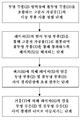
도 4. 발명에 따른 방법의 세부적인 흐름도.BRIEF DESCRIPTION OF THE DRAWINGS The invention is described in detail with reference to the drawings and exemplary embodiments thereof. The drawings are schematic representations and are not drawn to scale. The drawings do not limit the invention in any way. The drawing shows:
Figure 1 is a top plan view of an embodiment of a laser-marked polymeric article according to the invention,
Figure 2 is a cross-sectional view taken along line A-A 'through the laser-marked polymeric workpiece according to the invention of Figure 1,
2a. An enlarged view of detail (Z) in Fig.
Figure 3 is a cross-sectional view taken along line A-A 'through the polymeric workpiece according to the invention of Figure 1 during laser marking,
4 is a detailed flowchart of the method according to the invention.
도 1 및 도 2 각각은 발명에 따른 고분자 가공물(1)의 세부를 묘사한다. 이는 승용차의 측면 창문 판유리이며 30 cm의 높이 및 28 cm의 폭을 가진다. 고분자 가공물(1)은 투명 부품(2)을 포함한다. 4 cm의 폭을 가진 불투명 부품(3)은 고분자 가공물(1)의 가장자리 영역에서 투명 부품(2)상에 원주방향으로 배열된다. 도 1은 불투명 부품(3)으로부터 돌려진 투명 부품(2)의 표면의 상평면도를 묘사한다. 불투명 부품(3)은 투명 부품(2)을 통해 상평면도에서 식별될 수 있다. 고분자 가공물(1)은 다중-부품 사출 성형에 의해 생산하였다. 투명 부품(2)은 4 mm의 두께를 가지며 폴리카르보네이트(PC)를 포함한다. 불투명 부품(3)은 2 mm의 두께를 가진다. 불투명 부품(3)은 광물질-충전된 폴리카르보네이트(PC), 폴리에틸렌 테레프탈레이트(PET) 혼합물을 포함한다. 불투명 부품(3)의 사출 성형을 위한 출발 물질은 테이진 케미칼즈 리미티드 (Teijin Chemicals Ltd. 팬라이트 Y-0346 컬러 No. TG6654 (Panlite Y-0346 Color No. TG6654))에 의해 제조되었다. 고분자 가공물(1)은 불투명 부품(3) 영역에서 투명하지 않다. 측면 창문 판유리는 따라서 불투명 부품(3)이 차량 내부를 향하도록 바람직하게 배열될 때, 관찰자에게 비가시적인 방식으로 차체에 연결 예컨대, 접착될 수 있다.1 and 2 each depict a detail of a
마크(4)는 불투명 부품(3)의 하나 이상의 영역에 배열된다. 마크(4)는 발명에 따라 투명 부품(2) 및 불투명 부품(3) 사이 경계면 상에서의 불투명 부품(3) 내로 도입된다. 마크(4)는 불투명 부품(3)의 표면상에 증백된 영역으로 실현된다. 마크(4)는 간단하게, 채워진 원으로서 묘사된다. 특히, 마크(4)는 예컨대, 제작자의 상징, 상표 상징, 제작자의 코드, 생산 일자 및/또는 승인 마크일 수 있다.The mark (4) is arranged in one or more areas of the opaque part (3). The
투명 부품(2) 및 불투명 부품(3) 사이 경계면상의 고분자 가공물(1)의 내부에서의 마크(4)의 발명에 따른 배열에 의해, 예컨대, 마크(4)는 환경적 영향 예컨대, 기계적 손상에 대해 유리하게 보호된다. 게다가, 레이저 마킹 후 마크(4)는 고분자 가공물(1)의 코팅(나타내지는 않음) 예컨대, 보호 도료 코팅의 도포로 코팅 분배 문제를 유발하지 않는다.By means of the arrangement according to the invention of the
도 2a는 도 2 내 원에 의해 확인되는 세부(Z)의 확대도를 묘사한다. 투명 부품(2)을 향하는 불투명 부품(3)의 표면 내로 도입된 마크(4)뿐만 아니라 투명 부품(2) 영역, 불투명 부품(3) 영역이 보여질 수 있다.Figure 2a depicts an enlarged view of detail (Z) identified by a circle in Figure 2. The area of the
도 3은 발명에 따른 레이저 마킹 동안 도 1의 고분자 가공물을 관통하는 A-A' 단면을 묘사한다. 레이저(5) 빔은 불투명 부품(3)으로부터 다른 쪽을 향하는 투명 부품(2)의 표면을 통해 고분자 가공물(1)로 들어간다. 레이저(5) 빔은 고분자 가공물(1)의 투명 부품(2) 및 불투명 부품(3) 사이 경계면 또는 계면 상에 렌즈(6)에 의해 초점 맞춰진다. 렌즈(6)의 초점 거리는 160 mm이다. 레이저(5)는 활성 매질로서 2 m 길이 이테르븀 도핑된 유리 섬유를 가진 다이오드-펌핑 섬유 레이저이다. 레이저(5)의 방출 파장은 약 1063 nm이다. 레이저(5)는 110 ns의 펄스 지속시간 및 60 kHz의 펄스 진동수를 가진 펄스 모드에서 작동된다. 거울(7)은 레이저(5)의 빔 경로에 배열된다. 거울(7)의 이동에 의해, 레이저(5) 빔의 초점은 고분자 가공물(1)의 투명 부품(2) 및 불투명 부품(3) 사이 경계면 너머로 이동될 수 있다.FIG. 3 depicts a cross-section taken along the line A-A 'through the polymeric workpiece of FIG. 1 during laser marking according to the invention. The
레이저(5) 빔은, 이미 수 밀리초의 범위 내 노출 시간 후, 불투명 부품(3)의 표면상에 명확한 증백을 유발한다. 고분자 가공물(1)의 투명 부품(2) 및 불투명 부품(3) 사이 경계면 너머로 초점 맞춰진 레이저(5) 빔의 이동에 의해, 마크(4)가 예컨대, 제작자의 상징, 제작자의 코드, 생산 일자 또는 승인 마크가 따라서 영구적으로 적용될 수 있다.The
도 4는 한 예로서, 레이저-마킹된 고분자 가공물(1)의 생산을 위한 발명에 따른 방법을 묘사한다.Figure 4 depicts, by way of example, a method according to the invention for the production of a laser-marked
도 1에 따른 발명에 따른 레이저-마킹된 고분자 가공물(1)의 시험 시편은 발명에 따른 방법을 이용하여 만들었다. 레이저 마킹은 레이저(5), 거울(7) 및 렌즈(6)를 포함하는, FOBA사의 레이저 마킹 시스템 DP20F를 이용하여 수행하였다. 마크는(4) 문자, 숫자 및 기하학적 도형을 포함한다. 모든 시험 시편에서, 마크(4)는 분명하게 인식가능하였다. 마크(4)의 최소 선 폭은 대략 0.1 mm이었다.Test specimens of the laser-marked
통상의 기술자는 고분자 가공물(1)의 마크(4)가 고분자 가공물(1)의 표면을 변화시키지 않는 간단하고 신뢰할 수 있는 방식으로 제공될 수 있다는 것을 예상하지 못하였고 놀랐다.It has been surprised that a typical technician did not expect that the
(1)
고분자 가공물
(2)
투명 부품
(3)
불투명 부품
(4)
마크
(5)
레이저
(6)
렌즈
(7)
조정 가능한 거울
A-A'
단면선
Z
고분자 가공물(1)의 세부(1) Polymeric materials
(2) Transparent parts
(3) opaque parts
(4) Mark
(5) Laser
(6) Lens
(7) Adjustable mirrors
AA 'section line
Details of the Z-polymer works (1)
Claims (16)
b) 불투명 부품(3)이 하나 이상의 레이저(5)를 이용하여 투명 부품(2)을 통해 조사되며, 공정에서 마크(4)가 불투명 부품(3)으로 도입되고, 여기서 마크(4)는 불투명 부품(3)의 증백이며, 불투명 부품(3)은 적어도 폴리카르보네이트를 포함하며, 상기 레이저(5)가 펄스 모드에서 작동되며 펄스 반복 진동수가 20 kHz 내지 150 kHz 사이인, 레이저 마킹된 고분자 가공물(1) 생산 방법.a) combining an opaque part (3) and a transparent part (2) comprising at least one coloring agent by multi-part injection molding to form a polymeric workpiece (1)
b) the opaque part 3 is irradiated through the transparent part 2 using one or more lasers 5 and in the process the mark 4 is introduced into the opaque part 3 where the mark 4 is opaque Characterized in that the opaque part (3) comprises at least polycarbonate and the laser (5) is operated in the pulse mode and the pulse repetition frequency is between 20 kHz and 150 kHz. Process (1) production method.
Applications Claiming Priority (3)
| Application Number | Priority Date | Filing Date | Title |
|---|---|---|---|
| EP11189471 | 2011-11-17 | ||
| EP11189471.3 | 2011-11-17 | ||
| PCT/EP2012/069994 WO2013072142A1 (en) | 2011-11-17 | 2012-10-10 | Laser-marked polymer workpiece |
Related Parent Applications (1)
| Application Number | Title | Priority Date | Filing Date |
|---|---|---|---|
| KR1020147013354A Division KR20140079844A (en) | 2011-11-17 | 2012-10-10 | Laser-marked polymer workpiece |
Publications (1)
| Publication Number | Publication Date |
|---|---|
| KR20160052811A true KR20160052811A (en) | 2016-05-12 |
Family
ID=47008602
Family Applications (2)
| Application Number | Title | Priority Date | Filing Date |
|---|---|---|---|
| KR1020147013354A KR20140079844A (en) | 2011-11-17 | 2012-10-10 | Laser-marked polymer workpiece |
| KR1020167011643A KR20160052811A (en) | 2011-11-17 | 2012-10-10 | Laser-marked polymer workpiece |
Family Applications Before (1)
| Application Number | Title | Priority Date | Filing Date |
|---|---|---|---|
| KR1020147013354A KR20140079844A (en) | 2011-11-17 | 2012-10-10 | Laser-marked polymer workpiece |
Country Status (8)
| Country | Link |
|---|---|
| US (2) | US9821585B2 (en) |
| EP (1) | EP2780172B1 (en) |
| JP (1) | JP5959663B2 (en) |
| KR (2) | KR20140079844A (en) |
| CN (1) | CN103917378B (en) |
| ES (1) | ES2567323T3 (en) |
| PL (1) | PL2780172T3 (en) |
| WO (1) | WO2013072142A1 (en) |
Families Citing this family (8)
| Publication number | Priority date | Publication date | Assignee | Title |
|---|---|---|---|---|
| EP2780172B1 (en) | 2011-11-17 | 2016-03-23 | Saint-Gobain Glass France | Laser-marked polymer workpiece |
| CN106627379A (en) * | 2017-01-22 | 2017-05-10 | 江苏海华汽车部件有限公司 | Car lane-changing dead zone alarming signal control system and device |
| DE102017108081A1 (en) * | 2017-04-13 | 2018-10-18 | HELLA GmbH & Co. KGaA | Method for identifying a lens of a lighting device of a vehicle |
| JP7119421B2 (en) | 2018-02-27 | 2022-08-17 | Agc株式会社 | Glass plate with identification mark and method for forming identification mark on glass plate |
| CN110933935B (en) * | 2018-07-20 | 2022-09-30 | 法国圣戈班玻璃厂 | Soldering tool for induction soldering |
| CN109367040B (en) * | 2018-09-28 | 2021-06-04 | 东莞华晶粉末冶金有限公司 | Intelligent wearable shell and manufacturing method thereof |
| US11359323B2 (en) * | 2018-11-27 | 2022-06-14 | Lg Electronics Inc. | Laundry treating apparatus |
| CN114083137A (en) * | 2021-11-18 | 2022-02-25 | 歌尔科技有限公司 | Double-radiation structure for laser, laser engraving method and plastic part with mark |
Family Cites Families (28)
| Publication number | Priority date | Publication date | Assignee | Title |
|---|---|---|---|---|
| DE3411797A1 (en) * | 1984-03-30 | 1985-10-10 | Bayer Ag, 5090 Leverkusen | METHOD FOR LABELING PLASTIC PARTS |
| JP3107982B2 (en) | 1994-10-31 | 2000-11-13 | 帝人化成株式会社 | Resin composition for laser marking |
| US5977514A (en) * | 1997-06-13 | 1999-11-02 | M.A. Hannacolor | Controlled color laser marking of plastics |
| DE19732306B4 (en) * | 1997-07-26 | 2006-10-12 | Volkswagen Ag | Individual vehicle identification |
| WO2000037362A1 (en) | 1998-12-18 | 2000-06-29 | Dmc?2¿ Degussa Metals Catalysts Cerdec Ag | Bismuth manganese oxide pigments |
| DE19944372A1 (en) * | 1999-09-16 | 2001-03-22 | Bayerische Motoren Werke Ag | Laser processing of a partially or wholly transparent plastic element to create visible patterns or symbols, involves grouping laser beams together to locally change the transparency |
| JP4379668B2 (en) * | 2001-03-19 | 2009-12-09 | 日本カラリング株式会社 | Multi-layer sheet for laser marking |
| US20020177065A1 (en) * | 2001-03-21 | 2002-11-28 | Sahi Hussein M. | Laser marking on a coated substrate |
| US7728048B2 (en) * | 2002-12-20 | 2010-06-01 | L-1 Secure Credentialing, Inc. | Increasing thermal conductivity of host polymer used with laser engraving methods and compositions |
| JP2004050213A (en) * | 2002-07-18 | 2004-02-19 | Y E Data Inc | Marking method for glass plate |
| JP2004323252A (en) * | 2003-04-21 | 2004-11-18 | Hideaki Fujita | Tempered glass marking method and tempered glass |
| JP2005324997A (en) * | 2004-05-17 | 2005-11-24 | Nippon Sheet Glass Co Ltd | Reinforced glass board with marking and its manufacturing method |
| GB0421863D0 (en) | 2004-10-01 | 2004-11-03 | Retainagroup Ltd | Apparatus for marking a vehicle |
| GB0500123D0 (en) * | 2005-01-06 | 2005-02-09 | Pilkington Plc | Glazing |
| JP2006256307A (en) * | 2005-02-21 | 2006-09-28 | Techno Polymer Co Ltd | Laminate for laser marking |
| JPWO2006101063A1 (en) | 2005-03-23 | 2008-09-04 | 日本カラリング株式会社 | Two-color molded body for laser marking and laser marking method |
| JP4794487B2 (en) * | 2007-03-22 | 2011-10-19 | ダイセルポリマー株式会社 | Resin structure capable of white marking and white mark forming structure |
| DE102007018402A1 (en) * | 2007-04-17 | 2008-10-23 | Panasonic Electric Works Europe Ag | Method for introducing a structure into a surface of a transparent workpiece |
| JP4740937B2 (en) * | 2007-12-18 | 2011-08-03 | 株式会社ハッポーライフ彩生 | Laser marker for glass marking and glass marking method |
| WO2010011227A1 (en) * | 2008-07-25 | 2010-01-28 | The Sabreen Group, Inc. | Method and system for laser marking |
| US20100040836A1 (en) * | 2008-08-12 | 2010-02-18 | Shenping Li | Method for providing sub-surface marks in polymeric materials |
| CH699407A1 (en) | 2008-08-25 | 2010-02-26 | Tecan Trading Ag | Sample tube with labeling. |
| US8647721B2 (en) | 2008-11-05 | 2014-02-11 | Exatec, Llc | Part marking of coated plastic substrates |
| JP5025667B2 (en) * | 2009-01-23 | 2012-09-12 | 油脂製品株式会社 | Laminated sheet for firing having identification part |
| DE102009029903A1 (en) * | 2009-06-19 | 2010-12-23 | Tesa Se | Method for applying permanently processed label on e.g. plate, involves loading laser transferring film with partially provided pigment layer and supporting layer by using laser, where pigment layer includes laser-sensitive pigment |
| JP2011016304A (en) * | 2009-07-09 | 2011-01-27 | Mitsubishi Engineering Plastics Corp | Molded body for laser marking and laser marking method |
| DE102009028937A1 (en) * | 2009-08-27 | 2011-03-03 | Evonik Röhm Gmbh | Sign for license plates comprising at least one translucent, retroreflective layer |
| EP2780172B1 (en) | 2011-11-17 | 2016-03-23 | Saint-Gobain Glass France | Laser-marked polymer workpiece |
-
2012
- 2012-10-10 EP EP12770128.2A patent/EP2780172B1/en active Active
- 2012-10-10 US US14/351,437 patent/US9821585B2/en active Active
- 2012-10-10 PL PL12770128.2T patent/PL2780172T3/en unknown
- 2012-10-10 JP JP2014541586A patent/JP5959663B2/en not_active Expired - Fee Related
- 2012-10-10 ES ES12770128.2T patent/ES2567323T3/en active Active
- 2012-10-10 KR KR1020147013354A patent/KR20140079844A/en active Application Filing
- 2012-10-10 CN CN201280055618.7A patent/CN103917378B/en active Active
- 2012-10-10 WO PCT/EP2012/069994 patent/WO2013072142A1/en active Application Filing
- 2012-10-10 KR KR1020167011643A patent/KR20160052811A/en not_active Application Discontinuation
-
2017
- 2017-10-20 US US15/789,930 patent/US10500882B2/en active Active
Also Published As
| Publication number | Publication date |
|---|---|
| US9821585B2 (en) | 2017-11-21 |
| EP2780172B1 (en) | 2016-03-23 |
| KR20140079844A (en) | 2014-06-27 |
| US10500882B2 (en) | 2019-12-10 |
| EP2780172A1 (en) | 2014-09-24 |
| JP5959663B2 (en) | 2016-08-02 |
| CN103917378B (en) | 2016-01-06 |
| WO2013072142A1 (en) | 2013-05-23 |
| US20180037045A1 (en) | 2018-02-08 |
| PL2780172T3 (en) | 2016-09-30 |
| CN103917378A (en) | 2014-07-09 |
| ES2567323T3 (en) | 2016-04-21 |
| US20140248476A1 (en) | 2014-09-04 |
| JP2015500749A (en) | 2015-01-08 |
Similar Documents
| Publication | Publication Date | Title |
|---|---|---|
| US10500882B2 (en) | Laser-marked polymer workpiece | |
| US20100040836A1 (en) | Method for providing sub-surface marks in polymeric materials | |
| JP2810151B2 (en) | Laser marking method | |
| US9534344B2 (en) | Dyeing method and dyeing apparatus | |
| KR20000071183A (en) | Laser marking of articles | |
| US10662581B2 (en) | Method for the partial coloring of plastic parts | |
| KR20110086550A (en) | Partmarking of coated plastic substrates | |
| EP3437857B1 (en) | Decorative sheet, decorative molded article and decorative module | |
| JP2012011689A (en) | Method and apparatus for laser marking | |
| US6982828B2 (en) | Microscope slide having a marking region | |
| KR101313646B1 (en) | Method for laser-marking on surface of resin article | |
| Ho et al. | Direct ultrafast laser writing of buried waveguides in Foturan glass | |
| JP2004002056A (en) | Method of coloring tempered glass | |
| JP2004050213A (en) | Marking method for glass plate | |
| ES2400421A1 (en) | Procedure for marking a surface of a domestic appliance component, and domestic appliance device with a domestic appliance component (Machine-translation by Google Translate, not legally binding) | |
| CN116929543A (en) | Glass article for a light sensor comprising a selectively patterned opaque layer and display system comprising the same | |
| EP4272972A1 (en) | Method for laser engraving and/or laser marking, laser marked and/or engraved article and article for laser engraving and/or laser marking | |
| EP4351830A1 (en) | Laser nano-structuring for highly transparent anti-fogging glass | |
| CN117203063A (en) | Method for locally coloring plastic parts using solid dyes in a color carrier layer | |
| DE102010010070A1 (en) | A marking device and method for marking value or security documents with high resolution | |
| JP2019115990A (en) | Laser marking method | |
| CZ20014550A3 (en) | Method for color lettering of plastic materials by making use of a laser |
Legal Events
| Date | Code | Title | Description |
|---|---|---|---|
| A107 | Divisional application of patent | ||
| A201 | Request for examination | ||
| E902 | Notification of reason for refusal | ||
| E902 | Notification of reason for refusal | ||
| E601 | Decision to refuse application |