KR20160028596A - Three dimensional image display device - Google Patents
Three dimensional image display device Download PDFInfo
- Publication number
- KR20160028596A KR20160028596A KR1020140117100A KR20140117100A KR20160028596A KR 20160028596 A KR20160028596 A KR 20160028596A KR 1020140117100 A KR1020140117100 A KR 1020140117100A KR 20140117100 A KR20140117100 A KR 20140117100A KR 20160028596 A KR20160028596 A KR 20160028596A
- Authority
- KR
- South Korea
- Prior art keywords
- pitch
- image display
- stereoscopic image
- display device
- pixels
- Prior art date
Links
Images


Classifications
-
- H—ELECTRICITY
- H04—ELECTRIC COMMUNICATION TECHNIQUE
- H04N—PICTORIAL COMMUNICATION, e.g. TELEVISION
- H04N13/00—Stereoscopic video systems; Multi-view video systems; Details thereof
-
- H—ELECTRICITY
- H04—ELECTRIC COMMUNICATION TECHNIQUE
- H04N—PICTORIAL COMMUNICATION, e.g. TELEVISION
- H04N13/00—Stereoscopic video systems; Multi-view video systems; Details thereof
- H04N13/30—Image reproducers
- H04N13/302—Image reproducers for viewing without the aid of special glasses, i.e. using autostereoscopic displays
- H04N13/305—Image reproducers for viewing without the aid of special glasses, i.e. using autostereoscopic displays using lenticular lenses, e.g. arrangements of cylindrical lenses
-
- G—PHYSICS
- G02—OPTICS
- G02B—OPTICAL ELEMENTS, SYSTEMS OR APPARATUS
- G02B30/00—Optical systems or apparatus for producing three-dimensional [3D] effects, e.g. stereoscopic images
- G02B30/20—Optical systems or apparatus for producing three-dimensional [3D] effects, e.g. stereoscopic images by providing first and second parallax images to an observer's left and right eyes
- G02B30/26—Optical systems or apparatus for producing three-dimensional [3D] effects, e.g. stereoscopic images by providing first and second parallax images to an observer's left and right eyes of the autostereoscopic type
- G02B30/27—Optical systems or apparatus for producing three-dimensional [3D] effects, e.g. stereoscopic images by providing first and second parallax images to an observer's left and right eyes of the autostereoscopic type involving lenticular arrays
- G02B30/29—Optical systems or apparatus for producing three-dimensional [3D] effects, e.g. stereoscopic images by providing first and second parallax images to an observer's left and right eyes of the autostereoscopic type involving lenticular arrays characterised by the geometry of the lenticular array, e.g. slanted arrays, irregular arrays or arrays of varying shape or size
-
- G—PHYSICS
- G02—OPTICS
- G02B—OPTICAL ELEMENTS, SYSTEMS OR APPARATUS
- G02B30/00—Optical systems or apparatus for producing three-dimensional [3D] effects, e.g. stereoscopic images
- G02B30/20—Optical systems or apparatus for producing three-dimensional [3D] effects, e.g. stereoscopic images by providing first and second parallax images to an observer's left and right eyes
- G02B30/26—Optical systems or apparatus for producing three-dimensional [3D] effects, e.g. stereoscopic images by providing first and second parallax images to an observer's left and right eyes of the autostereoscopic type
- G02B30/30—Optical systems or apparatus for producing three-dimensional [3D] effects, e.g. stereoscopic images by providing first and second parallax images to an observer's left and right eyes of the autostereoscopic type involving parallax barriers
- G02B30/32—Optical systems or apparatus for producing three-dimensional [3D] effects, e.g. stereoscopic images by providing first and second parallax images to an observer's left and right eyes of the autostereoscopic type involving parallax barriers characterised by the geometry of the parallax barriers, e.g. staggered barriers, slanted parallax arrays or parallax arrays of varying shape or size
-
- H—ELECTRICITY
- H04—ELECTRIC COMMUNICATION TECHNIQUE
- H04N—PICTORIAL COMMUNICATION, e.g. TELEVISION
- H04N13/00—Stereoscopic video systems; Multi-view video systems; Details thereof
- H04N13/30—Image reproducers
- H04N13/302—Image reproducers for viewing without the aid of special glasses, i.e. using autostereoscopic displays
- H04N13/31—Image reproducers for viewing without the aid of special glasses, i.e. using autostereoscopic displays using parallax barriers
-
- H—ELECTRICITY
- H04—ELECTRIC COMMUNICATION TECHNIQUE
- H04N—PICTORIAL COMMUNICATION, e.g. TELEVISION
- H04N13/00—Stereoscopic video systems; Multi-view video systems; Details thereof
- H04N13/30—Image reproducers
- H04N13/302—Image reproducers for viewing without the aid of special glasses, i.e. using autostereoscopic displays
- H04N13/317—Image reproducers for viewing without the aid of special glasses, i.e. using autostereoscopic displays using slanted parallax optics
Landscapes
- Physics & Mathematics (AREA)
- Engineering & Computer Science (AREA)
- Multimedia (AREA)
- Signal Processing (AREA)
- Optics & Photonics (AREA)
- General Physics & Mathematics (AREA)
- Geometry (AREA)
- Testing, Inspecting, Measuring Of Stereoscopic Televisions And Televisions (AREA)
Abstract
Description
본 발명은 입체 영상 표시 장치에 관한 것으로서, 더 구체적으로 무안경 방식의 입체 영상 표시 장치에 관한 것이다.The present invention relates to a stereoscopic image display apparatus, and more particularly, to a stereoscopic image display apparatus of a non-eyeglass system.
최근에 표시 장치 기술의 발전에 따라서 3차원(3 dimensional, 3D)의 입체 영상 표시 장치가 관심을 끌고 있으며, 다양한 3차원 영상 표시 방법이 연구되고 있다.Recently, three-dimensional (3D) stereoscopic image display devices have attracted attention due to development of display device technology, and various 3D image display methods have been studied.
일반적으로, 3차원 영상 표시 기술에서는 근거리에서 입체감을 인식하는 가장 큰 요인인 양안 시차(binocular parallax)를 이용하여 물체의 입체감을 표현한다. 즉, 왼쪽 눈(좌안)과 오른쪽 눈(우안)에는 각각 서로 다른 2차원 영상이 비춰지고, 좌안에 비춰지는 영상(이하, "좌안 영상(left eye image) "이라 함)과 우안에 비춰지는 영상(이하, "우안 영상(right eye image) "이라 함)이 뇌로 전달되면, 좌안 영상과 우안 영상은 뇌에서 융합되어 깊이감(depth perception)을 갖는 3차원 영상으로 인식된다.Generally, in a three-dimensional image display technology, binocular parallax, which is the greatest factor for recognizing a three-dimensional sensation in a short distance, is used to express a stereoscopic effect of an object. In other words, different two-dimensional images are projected on the left eye (left eye) and the right eye (right eye), and images (hereinafter referred to as "left eye image") and images (Hereinafter referred to as "right eye image") is transmitted to the brain, the left eye image and the right eye image are recognized as a three-dimensional image having a depth perception fused in the brain.
입체 영상 표시 장치는 양안시차를 이용하는 것으로, 셔터 글래스(shutter glasses), 편광 안경(polarized glasses) 등의 안경을 이용하는 안경식(stereoscopic) 입체 영상 표시 장치와 안경을 이용하지 않고 표시 장치에 렌티큘러 렌즈(lenticular lens), 패럴랙스 배리어(parallax barrier) 등의 광학계를 배치하는 무안경식(autostereoscopic) 입체 영상 표시 장치가 있다.The stereoscopic image display device utilizes binocular parallax and is a stereoscopic stereoscopic image display device using glasses such as shutter glasses and polarized glasses and a stereoscopic display device using a lenticular lens an autostereoscopic stereoscopic image display device in which an optical system such as a lens, a parallax barrier, or the like is disposed.
무안경식 방식은 렌티큘러 렌즈 또는 복수의 개구부를 가지는 패럴랙스 배리어 등을 이용하여 입체 영상을 여러 시점(view point)으로 분리하여 표시함으로써 입체 영상을 구현한다. In the non-eye hardening method, a stereoscopic image is realized by separating a stereoscopic image into a plurality of view points by using a lenticular lens or a parallax barrier having a plurality of openings.
본 발명이 해결하고자 하는 기술적 과제는 무안경식 입체 영상 표시 장치에서 하나의 시점 분할부로 포트레이트 모드와 랜드스케이프 모드를 제공하고, 모아레(moire)의 발생을 억제하고 종합적으로 화질을 개선할 수 있는 입체 영상 표시 장치를 제공하는데 있다.SUMMARY OF THE INVENTION It is an object of the present invention to provide a stereoscopic image display apparatus which provides a portrait mode and a landscape mode as one viewpoint division unit in a non-eye-tightening stereoscopic image display apparatus and is capable of suppressing the occurrence of moire, And a video display device.
본 발명의 일 실시예에 따른 입체 영상 표시 장치는 행렬 형태로 배열되어 있는 복수의 화소를 포함하는 표시판; 및 복수의 상기 화소를 대응되는 복수의 시점으로 분할하는 시점 분할부를 포함하고, 상기 시점 분할부는 경사각에 따라 기울어진 복수의 시점 분할 유닛을 포함하고, 상기 화소의 행 방향의 피치를 Hp라 하고, 상기 화소의 열 방향의 피치를 Vp라 하고, Hp>Vp일 때, 상기 경사각은 
상기 시점 분할 유닛에 의해 관찰되는 각 화소의 행 방향의 폭은 Hp/(3b+c)이 되고, 상기 시점 분할 유닛에 의해 관찰되는 각 화소의 열 방향의 폭은 Vp/b이 되도록 구성될 수 있다.The width in the row direction of each pixel observed by the viewpoint division unit becomes Hp / (3b + c), and the width in the column direction of each pixel observed by the viewpoint division unit may be configured to be Vp / b have.
상기 시점 분할 유닛은 렌티큘러 렌즈이고, 상기 렌티큘러 렌즈의 행 방향의 렌즈 피치를 Lh라 하고, 상기 렌티큘러 렌즈의 열 방향의 렌즈 피치를 Lv라 할 때, 상기 렌티큘러 렌즈의 각 렌즈 피치는 
상기 시점 분할 유닛은 패럴랙스 배리어이고, 상기 패럴랙스 배리어의 행 방향의 개구부 피치를 Lh라 하고, 상기 패럴랙스 배리어의 열 방향의 개구부 피치를 Lv라 할 때, 상기 패럴랙스 배리어의 각 개구부 피치는 
상기 입체 영상 표시 장치의 랜드스케이프 모드의 계산 상의 양안 거리를 El라 하고, 상기 입체 영상 표시 장치의 포트레이트 모드의 계산 상의 양안 거리를 Ep라 하고, 인간 평균 양안 거리를 E라 할 때, El은 

E는 62mm 내지 65mm일 수 있다.E may be between 62 mm and 65 mm.
El 및 Ep의 평균치가 E가 되도록 구성될 수 있다.And the average value of El and Ep is E.
관찰자의 눈과 상기 시점 분할부 사이의 거리를 d라 하고, 상기 시점 분할부와 상기 표시판과의 거리를 g라 하고, 랜드스케이프 모드에서 상기 시점 분할 유닛의 렌즈 피치 또는 개구부 피치에 대응되는 상기 표시판 상의 거리를 kl라 할 때, ![]()
![]()
![]()
![]()
관찰자의 눈과 상기 시점 분할부 사이의 거리를 d라 하고, 상기 시점 분할부와 상기 표시판과의 거리를 g라 하고, 포트레이트 모드에서 상기 시점 분할 유닛의 렌즈 피치 또는 개구부 피치에 대응되는 상기 표시판 상의 거리를 kp라 할 때, ![]()
![]()
![]()
![]()
b는 1보다 큰 자연수일 수 있다.b may be a natural number greater than one.
b는 4이고 c는 -1일 때의 상기 경사각을 가질 수 있다.b is 4, and c is -1.
n은 근접 화소 세트의 화소의 개수이고, kl은 

본 발명의 실시예에 따르면 무안경식 입체 영상 표시 장치에서 하나의 시점 분할부로 포트레이트 모드와 랜드스케이프 모드를 제공할 수 있으며, 모아레의 발생을 억제하고 종합적으로 화질을 개선할 수 있는 입체 영상 표시 장치를 제공할 수 있다.According to an embodiment of the present invention, a stereoscopic image display device capable of providing a portrait mode and a landscape mode as one viewpoint division unit in an eye-freezing stereoscopic image display device, suppressing generation of moire, and comprehensively improving image quality Can be provided.
도 1은 본 발명의 한 실시예에 따른 입체 영상 표시 장치의 개략적인 사시도이다.
도 2는 본 발명의 한 실시예에 따른 입체 영상 표시 장치의 개략적인 측면 사시도이다.
도 3은 시점 분할 유닛이 렌티큘러 렌즈일 때 시점 분할부에 의한 시점을 도시한 도면이다.
도 4는 시점 분할 유닛이 패럴랙스 배리어일 때 시점 분할부에 의한 시점을 도시한 도면이다.
도 5는 포트레이트 모드와 랜드스케이프 모드를 설명하기 위한 예시도이다.
도 6은 본 발명의 경사각에 따라 기울어진 시점 분할 유닛을 설명하기 위한 예시도이다.
도 7 및 8은 각각 본 발명의 시점 분할 유닛에 의해 관찰되는 각 화소의 행 방향의 폭 및 열 방향의 폭을 설명하기 위한 예시도이다.
도 9는 시점 분할 유닛이 렌티큘러 렌즈일 때, 행 방향의 렌즈 피치와 열 방향의 렌즈 피치를 설명하기 위한 예시도이다.
도 10은 시점 분할 유닛이 패럴랙스 배리어일 때, 행 방향의 개구부 피치와 열 방향의 개구부 피치를 설명하기 위한 예시도이다.
도 11은 경사각에 따른 크로스토크, 제어 단위 크기, 및 디포커스량을 설명하기 위한 예시도이다.
도 12는 디포커스량을 계산하는 과정을 설명하기 위한 예시도이다.
도 13은 랜드스케이프 모드에서 3D 모드 및 2D 모드의 해상도 설명을 위한 예시도이다.
도 14는 포트레이트 모드에서 3D 모드 및 2D 모드의 해상도 설명을 위한 예시도이다.
도 15는 렌즈 피치를 구성하기 위한 화소 설계의 한 실시예를 도시한 도면이다.
도 16은 계산상의 양안 거리를 이용한 최적 관찰 거리의 설계를 설명하기 위한 예시도이다.
도 17은 랜드스케이프 모드의 계산상의 양안 거리를 이용하여 구성한 입체 영상 표시 장치의 예시도이다.
도 18은 포트레이트 모드의 계산상의 양안 거리를 이용하여 구성한 입체 영상 표시 장치의 예시도이다.
도 19는 도 15 내지 18의 설계에 따른 입체 영상 표시 장치의 각 수치를 나타낸 표를 도시한 도면이다.
도 20은 렌즈 피치를 구성하기 위한 화소 설계의 다른 실시예를 도시한 도면이다.
도 21은 도 20의 설계에 따른 입체 영상 표시 장치의 각 수치를 나타낸 표를 도시한 도면이다.1 is a schematic perspective view of a stereoscopic image display apparatus according to an embodiment of the present invention.
2 is a schematic side elevational view of a stereoscopic image display apparatus according to an embodiment of the present invention.
3 is a view showing the viewpoint by the viewpoint division unit when the viewpoint division unit is a lenticular lens.
4 is a view showing a viewpoint by a time division unit when the viewpoint division unit is a parallax barrier;
5 is an exemplary diagram for explaining the portrait mode and the landscape mode.
6 is an exemplary view for explaining a viewpoint division unit inclined according to the inclination angle of the present invention.
Figs. 7 and 8 are diagrams for explaining the widths in the row direction and the widths in the column direction of each pixel observed by the viewpoint division unit of the present invention. Fig.
9 is an exemplary view for explaining the lens pitch in the row direction and the lens pitch in the column direction when the viewpoint division unit is a lenticular lens.
10 is an exemplary view for explaining the pitch of openings in the row direction and the pitch of openings in the column direction when the viewpoint division unit is a parallax barrier;
11 is an exemplary view for explaining the crosstalk, the control unit size, and the defocus amount according to the tilt angle.
12 is an exemplary diagram for explaining a process of calculating a defocus amount.
13 is an exemplary diagram for explaining resolutions of the 3D mode and the 2D mode in the landscape mode.
14 is an exemplary diagram for explaining resolutions of the 3D mode and the 2D mode in the portrait mode.
15 is a diagram showing an embodiment of a pixel design for constituting a lens pitch.
FIG. 16 is an exemplary diagram for explaining the design of the optimum observation distance using the calculated binocular distance. FIG.
17 is an exemplary view of a stereoscopic image display apparatus configured by using a calculated binocular distance in a landscape mode.
18 is an exemplary view of a stereoscopic image display apparatus configured by using a calculated binocular distance in a portrait mode.
19 is a table showing respective numerical values of the stereoscopic image display device according to the designs of FIGS. 15 to 18. FIG.
20 is a view showing another embodiment of the pixel design for constituting the lens pitch.
FIG. 21 is a table showing respective numerical values of the stereoscopic image display device according to the design of FIG. 20. FIG.
이하, 첨부한 도면을 참고로 하여 본 발명의 실시예들에 대하여 본 발명이 속하는 기술 분야에서 통상의 지식을 가진 자가 용이하게 실시할 수 있도록 상세히 설명한다. 본 발명은 여러 가지 상이한 형태로 구현될 수 있으며 여기에서 설명하는 실시예들에 한정되지 않는다.Hereinafter, exemplary embodiments of the present invention will be described in detail with reference to the accompanying drawings, which will be readily apparent to those skilled in the art to which the present invention pertains. The present invention may be embodied in many different forms and is not limited to the embodiments described herein.
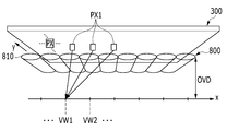
도 1은 본 발명의 한 실시예에 따른 입체 영상 표시 장치의 개략적인 사시도이다.1 is a schematic perspective view of a stereoscopic image display apparatus according to an embodiment of the present invention.
도 1을 참조하면, 본 발명의 한 실시예에 따른 입체 영상 표시 장치는 표시판(300), 표시판 구동부(350), 시점 분할부(800) 및 시점 분할부 구동부(850)를 포함한다.Referring to FIG. 1, a stereoscopic image display apparatus according to an embodiment of the present invention includes a
표시판(300)은 영상을 표시하며, 플라즈마 표시 장치(plasma display panel, PDP), 액정 표시 장치(liquid crystal display), 유기 발광 표시 장치(organic light emitting display) 등의 다양한 표시 장치 중 하나를 포함할 수 있다.The
도 2는 본 발명의 한 실시예에 따른 입체 영상 표시 장치의 개략적인 측면 사시도이다. 2 is a schematic side elevational view of a stereoscopic image display apparatus according to an embodiment of the present invention.
도 2를 참조하면, 표시판(300)은 등가 회로로 볼 때 복수의 신호선과 이에 연결되어 있는 복수의 화소(PX)를 포함한다. 복수의 화소(PX)는 대략 행렬의 형태로 배열될 수 있다. 도 2에서 행 방향은 x축 방향으로 표시하고, 열 방향은 y축 방향으로 표시한다. 각 화소(PX)는 신호선에 연결되어 있는 박막 트랜지스터 등의 스위칭 소자(도시하지 않음)와 이에 연결된 화소 전극(도시하지 않음)을 포함할 수 있다. 신호선은 게이트 신호("주사 신호"라고도 함)를 전달하는 복수의 게이트선과 데이터 전압을 전달하는 복수의 데이터선을 포함할 수 있다.Referring to FIG. 2, the
화소(PX)가 기본색(primary color) 중 하나를 고유하게 표시(공간 분할)하거나 복수 개의 화소(PX)가 시간에 따라 번갈아 기본색을 표시(시간 분할)함으로써 이들 기본색의 공간적 또는 시간적 합으로 원하는 색상이 표시될 수 있다. 기본색들은 삼원색, 사원색 등 다양한 조합일 수 있으나, 본 실시예에서는 적색(R), 녹색(G), 청색(B) 등 삼원색을 예로 들어 설명한다. 서로 다른 기본색을 표시하는 한 세트의 화소(PX)는 함께 하나의 도트를 이룰 수 있다. 하나의 도트는 입체 영상의 표시 단위일 수 있다. 한 화소 열의 화소(PX)들은 동일한 기본색을 나타낼 수 있으나 이에 한정되는 것은 아니고, x축 또는 y축을 기준으로 소정의 각도를 가지는 대각 방향으로 나열된 화소(PX)들이 동일한 기본색을 나타낼 수도 있다.The spatial or temporal sum of these basic colors can be obtained by pixel (PX) uniquely displaying (spatial division) one of the primary colors or by displaying a plurality of pixels (PX) The desired color can be displayed. The basic colors may be various combinations such as three primary colors, temple colors, etc. In the present embodiment, three primary colors such as red (R), green (G), and blue (B) are used as examples. A set of pixels PX indicating different basic colors can form one dot together. One dot may be a display unit of the stereoscopic image. The pixels PX of one pixel row may represent the same basic color but are not limited thereto and the pixels PX arranged in the diagonal direction having a predetermined angle with respect to the x axis or the y axis may represent the same basic color.
표시판 구동부(350)는 표시판(300)에 게이트 신호, 데이터 신호 등의 각종 구동 신호를 전달하여 표시판(300)을 구동한다.The
도 2를 참조하면, 시점 분할부(800)는 표시판(300)의 화소(PX)가 표시하는 영상의 빛을 분할하여 각 화소(PX)에 대응하는 시점(view point)(VW1, VW2,...)으로 보낸다.2, the
입체 영상 표시 장치로부터 최적의 입체 영상을 관찰할 수 있는 지점까지의 거리를 최적 관찰 거리(optimal viewing distance, OVD)라 한다. 최적 관찰 거리(OVD)에 위치한 x축 상에서 각 화소(PX)가 표시하는 영상(이하, 화소 영상이라 함.)이 시점 분할부(800)를 통해 도달하는 지점을 시점(view point)이라 할 수 있다.The distance from the stereoscopic image display device to the point where an optimal stereoscopic image can be observed is called an optimal viewing distance (OVD). A point at which an image represented by each pixel PX (hereinafter referred to as a pixel image) on the x-axis located at the optimum observation distance OVD reaches through the
본 발명의 한 실시예에 따르면 표시판(300)의 각 화소(PX)는 어느 한 시점(VW1, VW2,...)에 대응하고, 각 화소(PX)의 화소 영상은 시점 분할부(800)를 통해 대응하는 시점(VW1, VW2,...)에 도달한다.Each pixel PX of the
관찰자는 양 눈으로 다른 시점의 서로 다른 영상을 관찰하고, 이를 통해 깊이감, 즉 입체감을 느낄 수 있다.The observer observes different images at different points of view with both eyes, and can feel the depth sense, that is, the three-dimensional feeling.
도 2에는 최적 관찰 거리(OVD)에 위치하는 유한 개의 시점(VW1, VW2,...)들이 도시되어 있다. 예를 들어 제1 화소(PX1)가 표시하는 영상이 관찰되는 시점이 제1 시점(VW1)이면, 복수의 제1 화소(PX1) 각각이 표시하는 영상은 시점 분할부(800)를 통해 제1 시점(VW1)에 도달할 수 있다.FIG. 2 shows a finite number of time points VW1, VW2, ... located at the optimum observation distance OVD. For example, if the time point at which the image displayed by the first pixel PX1 is observed is the first time point VW1, the image displayed by each of the plurality of first pixels PX1 is divided into the first The time point VW1 can be reached.
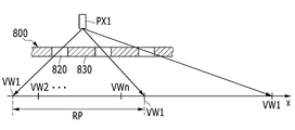
도 3은 시점 분할 유닛이 렌티큘러 렌즈일 때 시점 분할부에 의한 시점을 도시한 도면이고, 도 4는 시점 분할 유닛이 패럴랙스 배리어일 때 시점 분할부에 의한 시점을 도시한 도면이다.FIG. 3 is a view showing a viewpoint by a viewpoint division unit when the viewpoint division unit is a lenticular lens, and FIG. 4 is a view showing a viewpoint by a viewpoint division unit when the viewpoint division unit is a parallax barrier.
도 3 또는 도 4를 참조하면, 표시판(300)이 표시하는 영상은 시점 분할부(800)를 통해 일정 시야각을 가지는 단위 시야 영역(unit view area)(RP)의 어느 한 시점(VW1-VWn)(n은 자연수)에 도달할 수 있다. 즉, 시점(VW1-VWn)은 어느 한 단위 시야 영역(RP) 안에 존재하며, 한 단위 시야 영역(RP) 안에서 빛이 도달하는 위치에 따라 복수의 화소(PX) 각각의 대응 시점이 할당될 수 있다.3 and 4, an image displayed on the
단위 시야 영역(RP)은 최적 관찰 거리(OVD) 상에서 주기적으로 반복될 수 있고, 각 단위 시야 영역(RP) 안에서 시점(VW1-VWn)의 순서는 일정할 수 있다.The unit field of view region RP can be periodically repeated on the optimal observation distance OVD and the order of the viewpoints VW1 to VWn in each unit field region RP can be constant.
도 2 및 도 3을 참조하면, 본 발명의 한 실시예에 따른 시점 분할부(800)는 복수의 시점 분할 유닛을 포함하며, 복수의 시점 분할 유닛은 한 방향으로 배열된 복수의 렌티큘러 렌즈(810)를 포함할 수 있다. 각 렌티큘러 렌즈(810)는 한 방향으로 길게 뻗을 수 있다. 각 렌티큘러 렌즈(810)에 대응하며 이웃하는 화소 행의 색배열은 서로 다를 수 있다. 즉, 각 렌티큘러 렌즈(810)에 대응하며 이웃하는 화소행의 첫 번째 화소(PX)가 나타내는 기본색은 서로 다를 수 있다. 이를 위해 각 렌티큘러 렌즈(810)의 연장 방향은 열 방향인 y축 방향과 예각을 이루며 기울어질 수도 있고, y축 방향에 대체로 나란할 수도 있다.Referring to FIGS. 2 and 3, the
도 4를 참조하면, 본 발명의 한 실시예에 따른 시점 분할부(800)는 복수의 시점 분할 유닛을 포함하며, 복수의 시점 분할 유닛은 패럴랙스 배리어의 복수의 개구부(820)일 수 있다. 패럴랙스 배리어는 개구부(820) 이외에 차광부(830)를 더 포함한다. 일렬로 배열된 개구부(820)들의 배열 방향은 렌즈의 연장 방향과 같이 열 방향인 y축 방향과 예각을 이루며 기울어질 수도 있고, y축 방향에 대체로 나란할 수도 있다. 시점 분할부(800)가 렌티큘러 렌즈(810) 대신 패럴랙스 배리어를 포함하는 경우 도면에서 렌티큘러 렌즈의 연장 방향은 한 시점에 대응하는 개구부(820)의 배열 방향을 나타내는 것으로 한다.Referring to FIG. 4, a
도 1 및 도 2는 시점 분할부(800)가 표시판(300)과 관찰자 사이에 위치하는 것으로 도시하고 있으나 이에 한정되는 것은 아니다.1 and 2 illustrate that the
시점 분할부 구동부(850)는 시점 분할부(800)에 연결되어 시점 분할부(800)를 구동하기 위한 구동 신호를 생성한다.The time
도 5는 포트레이트 모드와 랜드스케이프 모드를 설명하기 위한 예시도이다.5 is an exemplary diagram for explaining the portrait mode and the landscape mode.
랜드스케이프 모드(landscape mode)는 화소(PX)의 행 방향의 피치(Hp)가 열 방향의 피치(Vp)보다 크게 형성되는 경우를 의미한다.The landscape mode means a case where the pitch Hp in the row direction of the pixel PX is formed larger than the pitch Vp in the column direction.
포트레이트 모드(landscape mode)는 화소(PX)의 열 방향의 피치가 행 방향의 피치보다 크게 형성되는 경우를 의미한다.The landscape mode means a case where the pitch in the column direction of the pixel PX is formed larger than the pitch in the row direction.
관찰자는 관찰하고자 하는 영상 또는 화면의 종류에 따라 입체 영상 표시 장치를 회전시킴으로써 랜드스케이프 모드와 포트레이트 모드를 선택할 수 있다. 각 모드의 선택에 따라 화소에 인가되는 데이터 및 표시판(300)의 해상도는 달라질 수 있다.The observer can select the landscape mode and the portrait mode by rotating the stereoscopic image display device according to the type of the image or screen to be observed. The data to be applied to the pixels and the resolution of the
랜드스케이프 모드는 가로 모드라고 하고, 포트레이트 모드를 세로 모드라고 하기도 한다.Landscape mode is called landscape mode, and portrait mode is called vertical mode.
본 발명에서는 기본적으로 랜드스케이프 모드를 기준으로 하여 화소(PX)의 행 방향의 피치(Hp) 및 열 방향의 피치(Vp)를 설명한다. 따라서 화소(PX)의 행 방향의 피치(Hp)는 열 방향의 피치(Vp)보다 크게 형성된다.In the present invention, the pitch Hp in the row direction and the pitch Vp in the column direction of the pixel PX are basically described with reference to the landscape mode. Therefore, the pitch Hp in the row direction of the pixel PX is formed larger than the pitch Vp in the column direction.
이때, 아래 수학식 1의 관계를 만족하도록 행 방향의 피치(Hp) 및 열 방향의 피치(Vp)가 형성될 수 있다.At this time, the pitch Hp in the row direction and the pitch Vp in the column direction may be formed so as to satisfy the relationship of the following equation (1).
[수학식 1][Equation 1]
Hp=3*VpHp = 3 * Vp
다만, 경우에 따라 포트레이트 모드를 위해 화소(PX)의 열 방향의 피치가 행 방향의 피치보다 큰 경우가 있을 수 있다.However, in some cases, the pitch in the column direction of the pixel PX may be larger than the pitch in the row direction for the portrait mode.
도 6은 본 발명의 경사각에 따라 기울어진 시점 분할 유닛을 설명하기 위한 예시도이다.6 is an exemplary view for explaining a viewpoint division unit inclined according to the inclination angle of the present invention.
랜드스케이프 모드 또는 포트레이트 모드에서 하나의 시점 분할부(800)로 입체 영상을 표시하고자 한다면 시점 분할 유닛의 경사각은 45도 부근으로 이루어질 수 있다.If the stereoscopic image is to be displayed by one
하지만 경사각이 45도인 경우에는 모아레(moire) 현상이 심각하게 발생하는 문제가 있다. 이는 모아레 현상 제거를 위해 필요한 디포커스(defocus)량이 커지기 때문이다. 디포커스량이 커지면 크로스토크(crosstalk)량도 함께 커지는 문제가 발생할 수 있다.However, when the inclination angle is 45 degrees, a moire phenomenon occurs seriously. This is because the amount of defocus necessary for removing the moire phenomenon is increased. If the defocus amount is increased, the amount of crosstalk may also increase.
따라서 본 발명에서는 시점 분할 유닛이 아래 수학식 2를 만족시키는 경사각으로 기울어져 있다. 이러한 경사각은 표시판(300)의 화소(PX)의 행 방향의 피치(Hp) 및 열 방향의 피치(Vp)을 기준으로 정의된다.Therefore, in the present invention, the viewpoint division unit is inclined at an inclination angle satisfying the following expression (2). This inclination angle is defined based on the pitch Hp in the row direction and the pitch Vp in the column direction of the pixel PX of the
[수학식 2]&Quot; (2) "

이때 c는 -1 또는 1 중 어느 하나이고, 바람직하게는 b는 1보다 큰 자연수이다.Where c is either -1 or 1, preferably b is a natural number greater than 1.
라인(600)은 경사각이 45도인 경우를 나타낸다.The
본 발명의 경사각은 라인(600)으로부터 수직 방향으로 화소 1개 분량만큼 커지거나 작아지는 각도일 수 있다.The inclination angle of the present invention may be an angle that is increased or decreased by one pixel in the vertical direction from the
라인(610)은 경사각이 c=-1이고, b=2인 경우를 나타낸다.
라인(620)은 경사각이 c=-1이고, b=3인 경우를 나타낸다.The
라인(630)은 경사각이 c=1이고, b=3인 경우를 나타낸다.
라인(640)은 경사각이 c=1이고, b=2인 경우를 나타낸다.
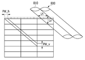
도 7 및 8은 각각 본 발명의 시점 분할 유닛에 의해 관찰되는 각 화소의 행 방향의 폭 및 열 방향의 폭을 설명하기 위한 예시도이다.Figs. 7 and 8 are diagrams for explaining the widths in the row direction and the widths in the column direction of each pixel observed by the viewpoint division unit of the present invention. Fig.
동일한 경사각을 갖는 시점 분할 유닛을 포함하는 시점 분할부(800) 및 표시판(300)으로 구성된 입체 영상 표시 장치라도, 시점 분할 유닛의 경사각에 맞추어 초점 거리를 조절함으로써 표시판(300)에 시점 분할 유닛을 통해 관찰되는 각 화소(PX)의 행 방향의 폭(PW_h) 및 열 방향의 폭(PW_v)이 조정될 수 있다.A stereoscopic image display apparatus including a
본 발명의 시점 분할 유닛에 의해 관찰되는 각 화소(PX)의 행 방향의 폭(PW_h)은 Hp/(3b+c)이 될 수 있다.The width PW_h in the row direction of each pixel PX observed by the viewpoint division unit of the present invention can be Hp / (3b + c).
이때, 본 발명의 시점 분할 유닛에 의해 관찰되는 각 화소(PX)의 열 방향의 폭(PW_v)은 Vp/b이 될 수 있다.At this time, the column width PW_v of each pixel PX observed by the viewpoint division unit of the present invention can be Vp / b.
도 7에서는 상술한 실시예에 따라 경사각이 c=-1이고 b=2인 경우에, 시점 분할 유닛에 의해 관찰되는 각 화소(PX)의 행 방향의 폭(PW_h) 및 열 방향의 폭(PW_v)을 도시한다.7, in the case where the inclination angle is c = -1 and b = 2 according to the embodiment described above, the width PW_h in the row direction and the width PW_v in the column direction of each pixel PX observed by the viewpoint division unit ).
도 8에서는 상술한 실시예에 따라 경사각이 c=-1이고 b=3인 경우에, 시점 분할 유닛에 의해 관찰되는 각 화소(PX)의 행 방향의 폭(PW_h) 및 열 방향의 폭(PW_v)을 도시한다.8, in the case where the inclination angle is c = -1 and b = 3 according to the embodiment described above, the width PW_h in the row direction and the width PW_v in the column direction of each pixel PX observed by the viewpoint division unit ).
도 9는 시점 분할 유닛이 렌티큘러 렌즈(810)일 때, 행 방향의 렌즈 피치(Lh)와 열 방향의 렌즈 피치(Lv)를 설명하기 위한 예시도이다.9 is an exemplary view for explaining the lens pitch Lh in the row direction and the lens pitch Lv in the column direction when the viewpoint division unit is the
본 발명의 렌티큘러 렌즈(810)의 행 방향의 렌즈 피치(Lh) 및 열 방향의 렌즈 피치(Lv)는 아래 수학식 3의 비율을 만족하도록 구성될 수 있다.The lens pitch Lh in the row direction and the lens pitch Lv in the column direction of the
[수학식 3]&Quot; (3) "

도 10은 시점 분할 유닛이 패럴랙스 배리어일 때, 행 방향의 개구부(820) 피치(Lh)와 열 방향의 개구부(820) 피치(Lv)를 설명하기 위한 예시도이다.10 is an exemplary view for explaining the pitch Lh of the
패럴랙스 배리어의 개구부(820)의 피치의 구성 원리는 도 9에서 시점 분할 유닛이 렌티큘러 렌즈일 때의 구성 원리와 유사할 수 있다.The constitution principle of the pitch of the
본 발명의 패럴랙스 배리어의 행 방향의 개구부(820) 피치(Lh) 및 열 방향의 개구부(820) 피치(Lv)는 수학식 3의 비율을 만족하도록 구성될 수 있다.The pitch Lh of the
도 11은 경사각에 따른 크로스토크, 제어 단위 크기, 및 디포커스량을 설명하기 위한 예시도이다.11 is an exemplary view for explaining the crosstalk, the control unit size, and the defocus amount according to the tilt angle.
크로스토크(crosstalk)는 좌안용 영상이 우측 눈에 보이거나 우안용 영상이 좌측 눈에 보이는 현상이다. 크로스토크가 크게 발생할 수록 정상적인 입체 영상을 시청할 수 없게 된다.Crosstalk is a phenomenon in which the left eye image is seen in the right eye or the right eye image is in the left eye. The larger the crosstalk is, the more the normal stereoscopic image can not be viewed.
헤드 트래킹(Head Tracking)은 관찰자의 이동을 추적하여 좌안용 이미지 및 우안용 이미지가 표시되는 도트를 바꿈으로써 크로스토크를 줄이는 기능이다. 관찰자가 이동함에 따라 크로스 토크가 점차 증가하여 50%가 되는 시점에 좌안용 이미지 및 우안용 이미지가 표시되는 도트를 바꾸는 방식으로 헤드 트래킹 기능이 수행될 수 있다.Head Tracking is a function to reduce the crosstalk by tracking the movement of the observer and changing the dot for the left eye image and the image for the right eye. The head tracking function can be performed by changing the dot for displaying the left-eye image and the right-eye image at a point where the crosstalk gradually increases to 50% as the observer moves.
헤드 트래킹의 제어 단위(control unit)는 최적 관찰 거리(OVD)에서 관찰자의 이동에 대응하여 좌안용 영상 및 우안용 영상이 표시되는 화소를 바꾸기 위해 검출해야 할 단위를 의미한다. 이때, 제어 단위는 최적 관찰 거리(OVD)에서 하나의 도트에 대응하는 폭이 될 수 있다.The control unit of the head tracking means a unit to be detected in order to change a pixel for displaying the left eye image and the right eye image corresponding to the movement of the observer at the optimum observation distance (OVD). At this time, the control unit may have a width corresponding to one dot at the optimum observation distance (OVD).
디포커스(defocus)량은 모아레 현상 제거를 위해 조절될 수 있다. 다만 디포커스량이 너무 크면 크로스토크가 발생할 여지가 있다.The amount of defocus can be adjusted for moiré removal. However, if the defocus amount is too large, crosstalk may occur.
도 11에서 크로스토크는 %단위로 기재되어 있으며, 괄호 기호 안에 헤드 트래킹(HT) 제어 단위의 크기가 mm단위로 기재되어 있다.In FIG. 11, the crosstalk is described in units of%, and the size of the head tracking (HT) control unit is described in the unit of mm in parentheses.
경사각이 45도인 라인(600)을 기준으로, 45도보다 큰 경사각을 가질수록 크로스토크가 작아지는 경향이 있다(제1 기준).The crosstalk tends to decrease as the inclination angle is larger than 45 degrees with respect to the
경사각의 기준이 되는 2개의 점이 서로 멀어질수록 크로스토크와 디포커스량은 작아지는 경향이 있다(제2 기준).The crosstalk and the defocus amount tend to be smaller as the two points of reference of the inclination angle become farther from each other (second criterion).
경사각의 기준이 되는 2개의 점이 서로 가까워질수록 제어 단위는 커지는 경향이 있다(제3 기준).The control unit tends to become larger as the two points of the inclination angle become closer to each other (third criterion).
제1 기준을 먼저 고려하고 제2 기준 및 제3 기준도 반영하여 최적의 경사각을 정하는 것이 바람직하다. 제3 기준의 제어 단위의 크기는 5mm이상이 바람직하다. 제어 단위를 크게 하면 디포커스량도 커지고, 따라서 모아레 현상이 발생할 수 있다.It is preferable to consider the first criterion first and also to determine the optimum tilt angle by reflecting the second criterion and the third criterion. The size of the control unit of the third criterion is preferably 5 mm or more. If the control unit is enlarged, the defocus amount also becomes large, and thus the moire phenomenon may occur.
도 11의 실시예에서는 경사각이 c는 -1이고 b는 4일 때, 크로스토크 발생량은 14.2%이고 제어 단위의 크기는 6.3mm가 되어 최적의 경사각(OA)을 찾을 수 있었다.In the embodiment of FIG. 11, when the inclination angle is c -1 and b is 4, the crosstalk generation amount is 14.2% and the control unit size is 6.3 mm, and the optimum inclination angle OA can be found.
도 12에서는 모아레 현상을 없애기 위한 디포커스량 계산 과정을 설명한다.12 illustrates a process of calculating a defocus amount for eliminating the moiré phenomenon.
도 11에서 찾은 경사각(OA)에 있어서, 랜드스케이프 모드와 포트레이트 모드의 모아레 현상 제거를 위한 디포커스량은 독립적으로 계산할 수 있다.In the inclination angle (OA) found in FIG. 11, the defocus amount for removing the moire phenomenon in the landscape mode and the portrait mode can be calculated independently.
이때 랜드스케이프 모드의 디포커스량은 Vp/4이고, 포트레이트 모드의 디포커스량은 Hp/11일 수 있다.At this time, the defocus amount in the landscape mode is Vp / 4 and the defocus amount in the portrait mode is Hp / 11.
도 12a는 시점 분할 유닛의 경사각과 디포커스량을 나타내고 있다. 라인(OA_l1)과 라인(OA_l2) 사이의 영역이 디포커스됨으로서 관찰되는 영역이다.12A shows the tilt angle and defocus amount of the viewpoint division unit. And the area between the lines OA_l 1 and
이때 도 12b에서 도시하는 바와 같이, 수직 방향에서는 Vp/4 크기, 수평 방향에서는 Hp/11 크기의 디포커스량이되어 모순이 발생하지 않는다. 10.1인치의 표시판(300) 경우, 실제 디포커스의 폭(x)는 아래 수학식 4를 통해 구할 수 있다.At this time, as shown in Fig. 12B, a defocus amount of Vp / 4 in the vertical direction and a defocus amount of Hp / 11 in the horizontal direction does not occur, and no contradiction occurs. In the case of the 10.1-
[수학식 4]&Quot; (4) "


도 13은 랜드스케이프 모드에서 3D 모드 및 2D 모드의 해상도 설명을 위한 예시도이다.13 is an exemplary diagram for explaining resolutions of the 3D mode and the 2D mode in the landscape mode.
도 13a 및 도 13b는 랜드스케이프 모드에서 세로 라인과 가로 라인을 표시할 경우에 실제로 관찰되는 이미지를 도시하고 있다.13A and 13B show images actually observed when vertical lines and horizontal lines are displayed in the landscape mode.
도 13b는 2D 모드의 경우로서, 흰색과 검은색 하나의 라인을 표시할 때, 1Hp의 피치로 표시할 수 있다.FIG. 13B shows a case of the 2D mode, and when displaying one line of white and black, it can be displayed with a pitch of 1Hp.
도 13a는 3D 모드의 경우로서, 24Hp/11의 피치로 흰색과 검은색 라인을 표시할 수 있다. 이때 해상도는 수평 방향에서 11/24으로 열화된다. 수직 방향에서의 해상도는 유지된다.13A is a case of the 3D mode, which can display white and black lines at a pitch of 24Hp / 11. At this time, the resolution is degraded to 11/24 in the horizontal direction. The resolution in the vertical direction is maintained.
도 14는 포트레이트 모드에서 3D 모드 및 2D 모드의 해상도 설명을 위한 예시도이다.14 is an exemplary diagram for explaining resolutions of the 3D mode and the 2D mode in the portrait mode.
도 14a 및 도14b는 포트레이트 모드에서 세로 라인과 가로 라인을 표시할 경우에 실제 관찰되는 이미지를 도시하고 있다.14A and 14B show images actually observed when vertical lines and horizontal lines are displayed in the portrait mode.
도 14b는 2D 모드의 경우로서, 흰색과 검은색 하나의 라인을 표시할 때, 3Hp의 피치로 표시할 수 있다.Fig. 14B is a 2D mode, and when displaying one line of white and black, it can be displayed at a pitch of 3Hp.
도 14a는 3D 모드의 경우로서, 6Hp의 피치로 흰색과 검은색 라인을 표시할 수 있다. 이때 해상도는 수평 방향에서 1/2으로 열화된다. 수직 방향에서는 RGB의 비율은 다르지만 라인마다 분리가 가능하다. 따라서 색 정보는 열화되지만 수직 방향의 해상도는 유지된다.14A is a case of the 3D mode, and white and black lines can be displayed at a pitch of 6Hp. At this time, the resolution is degraded to 1/2 in the horizontal direction. In the vertical direction, although the ratio of RGB is different, it is possible to separate each line. Therefore, the color information deteriorates but the resolution in the vertical direction is maintained.
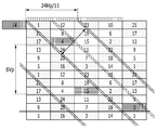
도 15는 목적하는 렌즈 피치를 구성하기 위한 화소 설계의 한 실시예를 도시한 도면이다.Fig. 15 is a diagram showing an embodiment of a pixel design for constituting a desired lens pitch.
근접 화소 세트(proximity dots, PD)란 어느 한 시점에 대한 영상을 나타내는 제1 화소에 대하여 동일한 렌티큘러 렌즈 또는 일렬로 배열된 패럴랙스 배리어의 개구부를 통해 관찰되는 동일한 시점의 다음 제2 화소가 있을 때, 동일한 렌티큘러 렌즈 또는 일렬로 배열된 패럴랙스 배리어의 개구부를 통해 관찰되는 제1 화소 및 제1 화소와 제2 화소 사이에 위치하는 화소의 집단을 의미한다. 근접 화소 세트(PD)의 화소들은 서로 다른 시점의 영상을 표시할 수도 있고 서로 동일한 시점의 영상을 표시할 수도 있다.The proximity dots PD are the same as the lenticular lens for the first pixel representing an image at a certain point in time or the next second pixel at the same point of time observed through the opening of the parallax barrier arranged in a row , A first pixel observed through an opening of the same lenticular lens or a parallax barrier arranged in a line, and a group of pixels located between a first pixel and a second pixel. The pixels of the adjacent pixel set PD may display images at different viewpoints or may display images at the same viewpoints.
근접 화소 세트(PD)의 화소 개수 n은 경사각이 아래 수학식 5과 같이 정의될 때, 아래 수학식 6과 같이 구해질 수 있다.The number n of pixels of the adjacent pixel set PD can be obtained as shown in Equation (6) below when the inclination angle is defined by Equation (5) below.
[수학식 5]&Quot; (5) "

[수학식 6]&Quot; (6) "
![]()
![]()
상술한 수학식 및 이하 수학식에서 m 값은 수학식 2 와 대응시킴으로써 3b+c로 이해될 수 있다.In the above-described equation and the following equation, the value of m can be understood as 3b + c by matching with equation (2).
도 15에서는 2Hp 또는 6Vp 이하의 렌즈 피치를 구성하기 위하여 근접 화소 세트(PD)를 구성하는 화소들 중 4개를 삭감하는 설계를 하고 있다.In Fig. 15, a design is made to reduce four of the pixels constituting the adjacent pixel set PD to constitute the lens pitch of 2Hp or 6Vp or less.
즉 도 15에서는 b=4, m=11인 경우로서 근접 화소 세트(PD)의 화소 개수 n=4+11-1=14로 계산되나, 4개 화소를 근접 화소 세트(PD)로부터 삭감하여 n=10이 된다. 이때 크로스토크는 증가하고 NA는 감소한다.15, b = 4 and m = 11, the number of pixels of the adjacent pixel set PD is calculated as n = 4 + 11-1 = 14. However, four pixels are subtracted from the adjacent pixel set PD, = 10. At this time, crosstalk increases and NA decreases.
구체적으로는 라인(650_l1)과 라인(650_l2) 사이의 디포커스된 영역에 중첩되는 근접 화소 세트(PD)를 구성하는 화소 1, 17, 8, 4, 20, 16, 7, 3, 19, 15, 6, 2, 18, 5 중에서 격자 표시된 화소 8, 16, 7, 15가 제외된다.Specifically,
시점 분할 유닛의 행 방향의 피치(Lv)에 대응되는 표시판(300) 상의 행 방향의 폭(kl)은 아래 수학식 7로 구할 수 있고, 열 방향의 폭(kp)은 아래 수학식 8으로 구할 수 있다. 이는 도 7 및 도 8의 실시예에서 상술한 PW_h 및 PW_v 값에 좌안용 근접 화소 세트와 우안용 근접 화소 세트를 구성하는 화소의 개수를 합한 값(2n)을 곱한 것이다.The width k1 in the row direction on the
[수학식 7]&Quot; (7) "
kl=2n*Hp/m=20Hp/11kl = 2n * Hp / m = 20Hp / 11
[수학식 8]&Quot; (8) "
kp=2n*Vp/b=5Vpkp = 2n * Vp / b = 5 Vp
이 경우 도 12에서 전술한 바와 같이 디포커스량은 Hp/11 및 Vp/4가 된다.In this case, the defocus amount becomes Hp / 11 and Vp / 4 as described above in Fig.
근접 화소 세트(PD) 상의 라인(650_l1)과 라인(650_l2) 사이의 디포커스된 영역의 전체 넓이는 8*2*11=176이다. 이때 단위는 하나의 화소를 8*22개로 구성하는 단위 격자(700)의 개수이다.The total width of the defocused area between the line 650_11 and the line 650_12 on the adjacent pixel set PD is 8 * 2 * 11 = 176. In this case, the unit is the number of
같은 방식으로 계산하면 크로스토크 영역의 넓이는 3*3+2*8=25이다. 따라서 크로스토크 발생률은 100*25/176=14.2%이다. 이러한 크로스토크 발생률은 최소값으로서 다른 디포커스된 영역에서는 더 크게 나타날 수도 있다. 따라서 실제로 적용시키기에는 큰 값이라고 볼 수 있다.When calculated in the same way, the width of the crosstalk area is 3 * 3 + 2 * 8 = 25. Therefore, the crosstalk occurrence rate is 100 * 25/176 = 14.2%. This crosstalk incidence rate may appear to be larger in other defocused areas as the minimum value. Therefore, it can be regarded as a large value for actual application.
도 16은 계산상의 양안 거리를 이용한 최적 관찰 거리의 설계를 설명하기 위한 예시도이다.FIG. 16 is an exemplary diagram for explaining the design of the optimum observation distance using the calculated binocular distance. FIG.
시점 분할 유닛의 행 방향의 피치(Lh)와 열 방향의 피치(Lv)의 비율은 kl과 kp의 비율과 동일할 수 있다. 따라서 아래 수학식 9의 의 관계가 성립할 수 있다.The ratio of the pitch Lh in the row direction of the viewpoint division unit to the pitch Lv in the column direction may be the same as the ratio of kl and kp. Therefore, the relationship of the following expression (9) can be established.
[수학식 9]&Quot; (9) "
![]()
![]()
살펴본 바와 같이 시점 분할 유닛의 행 방향의 피치(Lh)와 열 방향의 피치(Lv)가 다르므로, 최적 관찰 거리(OVD)를 설계할 때에는 두 개의 피치의 평균치(La)를 양안 거리에 대응시키는 것이 바람직하다. 이때 La=(Lh+Lv)/2를 만족할 수 있다.Since the pitch Lh in the row direction and the pitch Lv in the column direction of the viewpoint division unit are different from each other, when designing the optimum observation distance OVD, the average value La of the two pitches is made to correspond to the binocular distance . At this time, La = (Lh + Lv) / 2 can be satisfied.
이때 양안 거리는 인간의 평균 양안 거리(E)인 것이 바람직하다.At this time, the binocular distance is preferably the average binocular distance (E) of the human being.
이때 랜드스케이프 모드의 계산 상의 양안 거리(El)는 La:E=Lh:El을 만족시킬 수 있다. 따라서 El은 아래 수학식 10를 만족시킬 수 있다.At this time, the computed binocular distance (El) in the landscape mode can satisfy La: E = Lh: El. Therefore, El can satisfy Equation (10) below.
[수학식 10]&Quot; (10) "

이때 포트레이트 모드의 계산 상의 양안 거리(Ep)는 La:E=Lv:Ep를 만족시킬 수 있다. 따라서 Ep는 아래 수학식 11을 만족시킬 수 있다.At this time, the computed binocular distance Ep in the portrait mode can satisfy La: E = Lv: Ep. Therefore, Ep can satisfy Equation (11) below.
[수학식 11]&Quot; (11) "

전술한 수학식들을 이용하여 구한 본 실시예의 평균치(La)는 (20Hp/11+5Hp/3)/2=115Hp/66일 수 있다. 이때 E=63mm일 수 있다.The average La of the present embodiment obtained using the above-described equations may be (20Hp / 11 + 5Hp / 3) / 2 = 115Hp / 66. E = 63 mm.
본 실시예에 따른 랜드스케이프 모드의 계산 상의 양안 거리(El)는 115/66:63=20/11:El의 수학식으로부터 El=66*63*20/(11*115)=65.7mm일 수 있다.The computed binocular distance El in the landscape mode according to the present embodiment can be El = 66 * 63 * 20 / (11 * 115) = 65.7 mm from the equation 115/66: 63 = 20/11: have.
본 실시예에 따른 포트레이트 모드의 계산 상의 양안 거리(Ep)는 115/66:63=5/3:Ep의 수학식으로부터 Ep=66*63*5/(3*115)=60.3mm일 수 있다.The computed binocular distance Ep in the portrait mode according to this embodiment may be Ep = 66 * 63 * 5 / (3 * 115) = 60.3 mm from the equation 115/66: 63 = 5 / .
도 17은 랜드스케이프 모드의 계산상의 양안 거리를 이용하여 구성한 입체 영상 표시 장치의 예시도이다.17 is an exemplary view of a stereoscopic image display apparatus configured by using a calculated binocular distance in a landscape mode.
최적 관찰 거리(OVD)의 계산에는 El 또는 Ep가 사용될 수 있다. 도 17의 실시예에서는 El을 사용한 경우를 도시한다.El or Ep can be used to calculate the optimum observation distance (OVD). In the embodiment of Fig. 17, El is used.
관찰자의 눈과 상기 시점 분할부 사이의 거리를 최적 관찰 거리(OVD)인 d라 하고, 시점 분할부(800)와 표시판(300)과의 거리를 g라 하고, 랜드스케이프 모드에서 시점 분할 유닛(800)의 렌즈(810) 피치(Lh)에 대응되는 표시판(300) 상의 거리를 kl이라 할 때, 다음 식들을 만족하도록 구성될 수 있다.The distance between the observer's eye and the viewpoint division is d, which is the optimal observation distance OVD, and the distance between the
[수학식 12]&Quot; (12) "
![]()
![]()
[수학식 13]&Quot; (13) "
![]()
![]()
도 18은 포트레이트 모드의 계산상의 양안 거리를 이용하여 구성한 입체 영상 표시 장치의 예시도이다. 도 18의 실시예에서는 Ep를 사용하여 최적 관찰 거리(OVD)를 계산한 경우를 도시한다.18 is an exemplary view of a stereoscopic image display apparatus configured by using a calculated binocular distance in a portrait mode. In the embodiment of FIG. 18, the case where the optimum observation distance OVD is calculated using Ep is shown.
관찰자의 눈과 상기 시점 분할부 사이의 거리를 최적 관찰 거리(OVD)인 d라 하고, 시점 분할부(800)와 표시판(300)과의 거리를 g라 하고, 포트레이트 모드에서 시점 분할 유닛(800)의 렌즈(810) 피치(Lv)에 대응되는 표시판(300) 상의 거리를 kp라 할 때, 다음 식들을 만족하도록 구성될 수 있다.The distance between the eye of the observer and the viewpoint division is defined as d which is the optimal observation distance OVD and the distance between the
[수학식 14]&Quot; (14) "
![]()
![]()
[수학식 15]&Quot; (15) "
![]()
![]()
도 19는 도 15 내지 18의 설계에 따른 입체 영상 표시 장치의 각 수치를 나타낸 표를 도시한 도면이다. 도 19a는 랜드스케이프 모드의 경우이고, 도 19b는 포트레이트 모드의 경우이다.19 is a table showing respective numerical values of the stereoscopic image display device according to the designs of FIGS. 15 to 18. FIG. FIG. 19A shows a case of the landscape mode, and FIG. 19B shows a case of the portrait mode.
랜드스케이프 모드에 65.7mm, 포트레이트 모드에 60.3mm를 채용하고 10.1인치의 표시판(300)의 최적 관찰 거리(OVD)와 NA를 계산하면 도 19의 표와 같다. 각각의 모드에 있어서 양안 거리에 다른 값을 채용함으로써 최적 관찰 거리(OVD)는 매우 근접한다.The table of FIG. 19 shows the optimum observation distance (OVD) and NA of the
도 20은 목적하는 렌즈 피치를 구성하기 위한 화소 설계의 다른 실시예를 도시한 도면이다.20 is a view showing another embodiment of the pixel design for constituting the objective lens pitch.
10.1인치의 표시판(300)에 있어서, 도 15의 실시예와 같이 시점 분할 유닛의 피치를 2Hp 또는 6Vp보다 작은 피치로 구현하면 NA 값은 문제가 없이 제조가 가능하다. 하지만 최적 관찰 거리(OVD)에 문제가 있음을 도 19의 표에서 알 수 있다. 따라서 도 20의 실시예에서는 최적 관찰 거리(OVD)를 더 짧게 하는 설계를 검토한다.In the case of the 10.1-
도 20의 실시예에서는 근접 화소 세트(PD)의 화소의 개수(n)에서 2개를 삭감하도록 구성한다. 즉 n=14-2=12이다.In the embodiment of Fig. 20, the number n of pixels in the adjacent pixel set PD is reduced by two. That is, n = 14-2 = 12.
각 수치의 계산 방법은 도 15와 동일하다. 계산된 결과는 다음과 같다. kl=24Hp/11, kp=6Vp로서 시점 분할 유닛의 렌즈 피치 또는 개구부 피치는 늘어났지만, 크로스토크 발생률은 5.1%로 현저하게 감소하였음을 알 수 있다.The calculation method of each numerical value is the same as in Fig. The calculated results are as follows. kl = 24Hp / 11 and kp = 6Vp, the lens pitch or aperture pitch of the viewpoint division unit is increased, but the crosstalk occurrence rate is remarkably reduced to 5.1%.
이때 경사각이 바뀌지 않았으므로, 디포커스량은 Hp/11 및 Vp/4이고, Lh:Lv=12:11이고, El은 65.7mm, Ep는 60.3mm로서 도 15와 동일하다. 따라서 최적 관찰 거리(OVD)의 설계는 도 15 내지 18의 경우와 기본적으로는 같다. 다른 점은 최적 관찰 거리(OVD)에 집광되는 우안의 이미지를 표시하는 화소 영역과 좌안의 이미지를 표시하는 화소 영역의 수가 각각 10개에서 12개로 증가되는 점이다.At this time, since the inclination angle is not changed, the defocus amount is Hp / 11 and Vp / 4, Lh: Lv = 12: 11, El is 65.7 mm, and Ep is 60.3 mm. Therefore, the design of the optimum observation distance (OVD) is basically the same as the case of Figs. 15 to 18. The difference is that the number of pixel regions displaying an image of the right eye and the number of pixel regions displaying an image of the left eye, which are converged at the optimum observation distance (OVD), are increased from 10 to 12, respectively.
이 경우 각 화소 영역의 크기(헤드 트래킹의 제어 단위)는 랜드스케이프 모드와 포트레이트 모드의 평균으로 5.25mm가 되므로, 5mm이상으로 정한 목표(제3 기준)가 달성된다.In this case, the size (control unit of head tracking) of each pixel area is 5.25 mm as an average of the landscape mode and the portrait mode, so that a target (third reference) set to 5 mm or more is achieved.
도 21은 도 20의 설계에 따른 입체 영상 표시 장치의 각 수치를 나타낸 표를 도시한 도면이다.FIG. 21 is a table showing respective numerical values of the stereoscopic image display device according to the design of FIG. 20. FIG.
도 19와 비교하였을 때, 최적 관찰 거리(OVD)는 상당히 개선되었음을 알 수 있고, NA 또한 좋은 점을 알 수 있다.Compared with FIG. 19, it can be seen that the optimum observation distance OVD is considerably improved, and the NA is also good.
지금까지 참조한 도면과 기재된 발명의 상세한 설명은 단지 본 발명의 예시적인 것으로서, 이는 단지 본 발명을 설명하기 위한 목적에서 사용된 것이지 의미 한정이나 특허청구범위에 기재된 본 발명의 범위를 제한하기 위하여 사용된 것은 아니다. 그러므로 본 기술 분야의 통상의 지식을 가진 자라면 이로부터 다양한 변형 및 균등한 타 실시 예가 가능하다는 점을 이해할 것이다. 따라서, 본 발명의 진정한 기술적 보호 범위는 첨부된 특허청구범위의 기술적 사상에 의해 정해져야 할 것이다. It is to be understood that both the foregoing general description and the following detailed description of the present invention are illustrative and explanatory only and are intended to be illustrative of the invention and are not to be construed as limiting the scope of the invention as defined by the appended claims. It is not. Therefore, those skilled in the art will appreciate that various modifications and equivalent embodiments are possible without departing from the scope of the present invention. Accordingly, the true scope of the present invention should be determined by the technical idea of the appended claims.
300: 표시판
350: 표시판 구동부
400: 제어부
800: 시점 분할부
810: 렌티큘러 렌즈
820: 개구부
830: 차광부
850: 시점 분할부 구동부300: Display panel
350:
400:
800:
810: Lenticular lens
820: opening
830: light shield
850:
Claims (13)
복수의 상기 화소를 대응되는 복수의 시점으로 분할하는 시점 분할부를 포함하고,
상기 시점 분할부는 경사각에 따라 기울어진 복수의 시점 분할 유닛을 포함하고,
상기 화소의 행 방향의 피치를 Hp라 하고, 상기 화소의 열 방향의 피치를 Vp라 하고, Hp>Vp일 때, 상기 경사각은 다음 식을 만족하고,

c는 -1 또는 1 중 하나인
입체 영상 표시 장치.A display panel including a plurality of pixels arranged in a matrix form; And
And a time division section for dividing the plurality of pixels into a plurality of corresponding time points,
Wherein the viewpoint division unit includes a plurality of viewpoint division units that are inclined according to a tilt angle,
The pitch of the pixels in the row direction is Hp, the pitch of the pixels in the column direction is Vp, and when Hp > Vp, the inclination angle satisfies the following expression,
c is either -1 or 1
Stereoscopic image display device.
상기 시점 분할 유닛에 의해 관찰되는 각 화소의 행 방향의 폭은 Hp/(3b+c)이 되고,
상기 시점 분할 유닛에 의해 관찰되는 각 화소의 열 방향의 폭은 Vp/b이 되도록 구성되는 입체 영상 표시 장치.The method according to claim 1,
The width in the row direction of each pixel observed by the viewpoint division unit becomes Hp / (3b + c)
And a width in a column direction of each pixel observed by the viewpoint division unit is Vp / b.
상기 시점 분할 유닛은 렌티큘러 렌즈이고,
상기 렌티큘러 렌즈의 행 방향의 렌즈 피치를 Lh라 하고, 상기 렌티큘러 렌즈의 열 방향의 렌즈 피치를 Lv라 할 때, 상기 렌티큘러 렌즈의 각 렌즈 피치는 다음 식의 비율을 만족하도록 구성되는

입체 영상 표시 장치.The method according to claim 1,
Wherein the viewpoint division unit is a lenticular lens,
And the lens pitch in the row direction of the lenticular lens is Lh and the lens pitch in the column direction of the lenticular lens is Lv, the respective lens pitches of the lenticular lenses satisfy the following expressions
Stereoscopic image display device.
상기 시점 분할 유닛은 패럴랙스 배리어이고,
상기 패럴랙스 배리어의 행 방향의 개구부 피치를 Lh라 하고, 상기 패럴랙스 배리어의 열 방향의 개구부 피치를 Lv라 할 때, 상기 패럴랙스 배리어의 각 개구부 피치는 다음 식의 비율을 만족하도록 구성되는

입체 영상 표시 장치.The method according to claim 1,
Wherein the viewpoint division unit is a parallax barrier,
The opening pitch in the row direction of the parallax barrier is Lh and the opening pitch in the column direction of the parallax barrier is Lv, the pitch of each opening of the parallax barrier satisfies the following expression
Stereoscopic image display device.
상기 입체 영상 표시 장치의 랜드스케이프 모드의 계산 상의 양안 거리를 El라 하고, 상기 입체 영상 표시 장치의 포트레이트 모드의 계산 상의 양안 거리를 Ep라 하고, 인간 평균 양안 거리를 E라 할 때,
El은 다음 식을 만족하고

Ep는 다음 식을 만족하는

입체 영상 표시 장치.The method according to claim 3 or 4,
When the binocular distance in the calculation of the landscape mode of the stereoscopic image display device is El, the binocular distance in calculation of the portrait mode of the stereoscopic image display device is Ep and the human mean binocular distance is E,
El satisfies the following equation
Ep satisfies the following equation
Stereoscopic image display device.
E는 62mm 내지 65mm인 입체 영상 표시 장치.6. The method of claim 5,
And E is 62 mm to 65 mm.
El 및 Ep의 평균치가 E가 되도록 구성되는 입체 영상 표시 장치.6. The method of claim 5,
And the average value of El and Ep is E.
관찰자의 눈과 상기 시점 분할부 사이의 거리를 d라 하고, 상기 시점 분할부와 상기 표시판과의 거리를 g라 하고,
랜드스케이프 모드에서 상기 시점 분할 유닛의 렌즈 피치 또는 개구부 피치에 대응되는 상기 표시판 상의 거리를 kl라 할 때,
다음 식들을 만족하도록 구성되는
입체 영상 표시 장치.6. The method of claim 5,
D is the distance between the observer's eye and the viewpoint division, g is the distance between the viewpoint division and the display panel,
When the distance on the display panel corresponding to the lens pitch or the aperture pitch of the viewpoint division unit in the landscape mode is kl,
And is configured to satisfy the following equations
Stereoscopic image display device.
관찰자의 눈과 상기 시점 분할부 사이의 거리를 d라 하고, 상기 시점 분할부와 상기 표시판과의 거리를 g라 하고,
포트레이트 모드에서 상기 시점 분할 유닛의 렌즈 피치 또는 개구부 피치에 대응되는 상기 표시판 상의 거리를 kp라 할 때,
다음 식들을 만족하도록 구성되는
입체 영상 표시 장치.6. The method of claim 5,
D is the distance between the observer's eye and the viewpoint division, g is the distance between the viewpoint division and the display panel,
When the distance on the display panel corresponding to the lens pitch or the aperture pitch of the viewpoint division unit in the portrait mode is kp,
And is configured to satisfy the following equations
Stereoscopic image display device.
b는 1보다 큰 자연수인 입체 영상 표시 장치.The method according to claim 1,
and b is a natural number greater than one.
b는 4이고 c는 -1일 때의 상기 경사각을 갖는
입체 영상 표시 장치.The method according to claim 1,
b is 4 and c is -1,
Stereoscopic image display device.
n은 근접 화소 세트의 화소의 개수이고,
kl은 다음 식을 만족하고,

kp는 다음 식을 만족하는

입체 영상 표시 장치.9. The method of claim 8,
n is the number of pixels in the set of adjacent pixels,
kl satisfies the following equation,
kp satisfies the following equation
Stereoscopic image display device.
n은 근접 화소 세트의 화소의 개수이고,
kl은 다음 식을 만족하고,

kp는 다음 식을 만족하는
입체 영상 표시 장치.10. The method of claim 9,
n is the number of pixels in the set of adjacent pixels,
kl satisfies the following equation,
kp satisfies the following equation
Stereoscopic image display device.
Priority Applications (2)
| Application Number | Priority Date | Filing Date | Title |
|---|---|---|---|
| KR1020140117100A KR20160028596A (en) | 2014-09-03 | 2014-09-03 | Three dimensional image display device |
| US14/664,304 US10244229B2 (en) | 2014-09-03 | 2015-03-20 | Three-dimensional image display device |
Applications Claiming Priority (1)
| Application Number | Priority Date | Filing Date | Title |
|---|---|---|---|
| KR1020140117100A KR20160028596A (en) | 2014-09-03 | 2014-09-03 | Three dimensional image display device |
Publications (1)
| Publication Number | Publication Date |
|---|---|
| KR20160028596A true KR20160028596A (en) | 2016-03-14 |
Family
ID=55404094
Family Applications (1)
| Application Number | Title | Priority Date | Filing Date |
|---|---|---|---|
| KR1020140117100A KR20160028596A (en) | 2014-09-03 | 2014-09-03 | Three dimensional image display device |
Country Status (2)
| Country | Link |
|---|---|
| US (1) | US10244229B2 (en) |
| KR (1) | KR20160028596A (en) |
Families Citing this family (5)
| Publication number | Priority date | Publication date | Assignee | Title |
|---|---|---|---|---|
| JP7120537B2 (en) * | 2017-10-31 | 2022-08-17 | 公立大学法人大阪 | THREE-DIMENSIONAL DISPLAY DEVICE, THREE-DIMENSIONAL DISPLAY SYSTEM, HEAD-UP DISPLAY, AND THREE-DIMENSIONAL DISPLAY DESIGN METHOD |
| JP2020134679A (en) * | 2019-02-19 | 2020-08-31 | 株式会社ジャパンディスプレイ | Display |
| EP3767946A1 (en) * | 2019-07-17 | 2021-01-20 | SeeFront GmbH | Base display for an autostereoscopic display assembly |
| JP7433631B2 (en) | 2020-01-16 | 2024-02-20 | 公立大学法人大阪 | 3D display device |
| JP2023063627A (en) * | 2021-10-25 | 2023-05-10 | 株式会社ジャパンディスプレイ | Display device |
Family Cites Families (9)
| Publication number | Priority date | Publication date | Assignee | Title |
|---|---|---|---|---|
| GB2317734A (en) | 1996-09-30 | 1998-04-01 | Sharp Kk | Spatial light modulator and directional display |
| JP3668116B2 (en) | 1999-09-24 | 2005-07-06 | 三洋電機株式会社 | 3D image display device without glasses |
| JP5665255B2 (en) | 2007-10-15 | 2015-02-04 | Nltテクノロジー株式会社 | Display device, driving method thereof, terminal device, and display panel |
| CN101946521B (en) * | 2008-02-11 | 2013-01-23 | 皇家飞利浦电子股份有限公司 | Autostereoscopic image output device |
| JP5521380B2 (en) | 2009-04-13 | 2014-06-11 | ソニー株式会社 | 3D display device |
| JP5286302B2 (en) | 2010-02-04 | 2013-09-11 | 株式会社東芝 | Stereoscopic image display device |
| JP2011197376A (en) | 2010-03-19 | 2011-10-06 | Sony Corp | Display device and electronic apparatus |
| JP2011197508A (en) | 2010-03-23 | 2011-10-06 | Sony Corp | Display device and electronic apparatus |
| KR20120021074A (en) | 2010-08-31 | 2012-03-08 | 엘지디스플레이 주식회사 | Stereoscopic 3d display device |
-
2014
- 2014-09-03 KR KR1020140117100A patent/KR20160028596A/en not_active Application Discontinuation
-
2015
- 2015-03-20 US US14/664,304 patent/US10244229B2/en active Active
Also Published As
| Publication number | Publication date |
|---|---|
| US10244229B2 (en) | 2019-03-26 |
| US20160065951A1 (en) | 2016-03-03 |
Similar Documents
| Publication | Publication Date | Title |
|---|---|---|
| EP2811746B1 (en) | Glasses-free 3d image display device for flattening field of view and minimizing dynamic crosstalk | |
| JP3966830B2 (en) | 3D display device | |
| JP4403162B2 (en) | Stereoscopic image display device and method for producing stereoscopic image | |
| US9766469B2 (en) | Stereoscopic image display device | |
| JP5465430B2 (en) | Control of angle range of autostereoscopic viewing zone | |
| JP5332978B2 (en) | 3D display device | |
| JP4331224B2 (en) | 3D image display device and 3D image display method | |
| US9674509B2 (en) | Multi-view 3D image display apparatus using modified common viewing zone | |
| JP2010524309A (en) | Method and configuration for three-dimensional display | |
| KR20160010169A (en) | Curved multiview image display apparatus and control method thereof | |
| KR20110049039A (en) | High density multi-view display system and method based on the active sub-pixel rendering | |
| KR101966152B1 (en) | Multi view image display apparatus and contorl method thereof | |
| KR20130107584A (en) | Method of displaying three dimensional stereoscopic image and display apparatus performing for the method | |
| KR101963392B1 (en) | Method for Generating Dynamic Maximal Viewing Zone of 3D Autostereoscopic Display | |
| KR20160062312A (en) | Three dimensional image display device | |
| KR20160028596A (en) | Three dimensional image display device | |
| KR20150055322A (en) | multi view image display apparatus and multi view image display method thereof | |
| KR20160058327A (en) | Three dimensional image display device | |
| KR20150055442A (en) | Three dimensional image display device | |
| KR20140134512A (en) | Three dimensional image display device and method of displaying three dimensional image | |
| KR101975246B1 (en) | Multi view image display apparatus and contorl method thereof | |
| KR102221773B1 (en) | Three dimensional image display device | |
| JP7335233B2 (en) | A system and method for displaying two-viewpoint autostereoscopic images on an N-viewpoint autostereoscopic display screen and a method for controlling the display on such a display screen | |
| KR101471654B1 (en) | Apparatus for 3-dimensional displaying having modified delta pixel structure | |
| KR102271171B1 (en) | Glass-free multiview autostereoscopic display device and method for image processing thereof |
Legal Events
| Date | Code | Title | Description |
|---|---|---|---|
| A201 | Request for examination | ||
| E902 | Notification of reason for refusal | ||
| E90F | Notification of reason for final refusal | ||
| E601 | Decision to refuse application |