KR20150131247A - Vane arrangement having alternating vanes with different trailing edge profile - Google Patents
Vane arrangement having alternating vanes with different trailing edge profile Download PDFInfo
- Publication number
- KR20150131247A KR20150131247A KR1020157029103A KR20157029103A KR20150131247A KR 20150131247 A KR20150131247 A KR 20150131247A KR 1020157029103 A KR1020157029103 A KR 1020157029103A KR 20157029103 A KR20157029103 A KR 20157029103A KR 20150131247 A KR20150131247 A KR 20150131247A
- Authority
- KR
- South Korea
- Prior art keywords
- stationary
- vane
- casing
- vanes
- diffuser
- Prior art date
Links
Images


Classifications
-
- F—MECHANICAL ENGINEERING; LIGHTING; HEATING; WEAPONS; BLASTING
- F01—MACHINES OR ENGINES IN GENERAL; ENGINE PLANTS IN GENERAL; STEAM ENGINES
- F01D—NON-POSITIVE DISPLACEMENT MACHINES OR ENGINES, e.g. STEAM TURBINES
- F01D9/00—Stators
- F01D9/02—Nozzles; Nozzle boxes; Stator blades; Guide conduits, e.g. individual nozzles
- F01D9/04—Nozzles; Nozzle boxes; Stator blades; Guide conduits, e.g. individual nozzles forming ring or sector
- F01D9/041—Nozzles; Nozzle boxes; Stator blades; Guide conduits, e.g. individual nozzles forming ring or sector using blades
-
- F—MECHANICAL ENGINEERING; LIGHTING; HEATING; WEAPONS; BLASTING
- F01—MACHINES OR ENGINES IN GENERAL; ENGINE PLANTS IN GENERAL; STEAM ENGINES
- F01D—NON-POSITIVE DISPLACEMENT MACHINES OR ENGINES, e.g. STEAM TURBINES
- F01D5/00—Blades; Blade-carrying members; Heating, heat-insulating, cooling or antivibration means on the blades or the members
- F01D5/12—Blades
- F01D5/14—Form or construction
- F01D5/141—Shape, i.e. outer, aerodynamic form
- F01D5/142—Shape, i.e. outer, aerodynamic form of the blades of successive rotor or stator blade-rows
-
- F—MECHANICAL ENGINEERING; LIGHTING; HEATING; WEAPONS; BLASTING
- F01—MACHINES OR ENGINES IN GENERAL; ENGINE PLANTS IN GENERAL; STEAM ENGINES
- F01D—NON-POSITIVE DISPLACEMENT MACHINES OR ENGINES, e.g. STEAM TURBINES
- F01D5/00—Blades; Blade-carrying members; Heating, heat-insulating, cooling or antivibration means on the blades or the members
- F01D5/12—Blades
- F01D5/14—Form or construction
- F01D5/141—Shape, i.e. outer, aerodynamic form
- F01D5/145—Means for influencing boundary layers or secondary circulations
-
- F—MECHANICAL ENGINEERING; LIGHTING; HEATING; WEAPONS; BLASTING
- F01—MACHINES OR ENGINES IN GENERAL; ENGINE PLANTS IN GENERAL; STEAM ENGINES
- F01D—NON-POSITIVE DISPLACEMENT MACHINES OR ENGINES, e.g. STEAM TURBINES
- F01D5/00—Blades; Blade-carrying members; Heating, heat-insulating, cooling or antivibration means on the blades or the members
- F01D5/12—Blades
- F01D5/14—Form or construction
- F01D5/16—Form or construction for counteracting blade vibration
-
- F—MECHANICAL ENGINEERING; LIGHTING; HEATING; WEAPONS; BLASTING
- F04—POSITIVE - DISPLACEMENT MACHINES FOR LIQUIDS; PUMPS FOR LIQUIDS OR ELASTIC FLUIDS
- F04D—NON-POSITIVE-DISPLACEMENT PUMPS
- F04D29/00—Details, component parts, or accessories
- F04D29/40—Casings; Connections of working fluid
- F04D29/42—Casings; Connections of working fluid for radial or helico-centrifugal pumps
- F04D29/4206—Casings; Connections of working fluid for radial or helico-centrifugal pumps especially adapted for elastic fluid pumps
- F04D29/4213—Casings; Connections of working fluid for radial or helico-centrifugal pumps especially adapted for elastic fluid pumps suction ports
-
- F—MECHANICAL ENGINEERING; LIGHTING; HEATING; WEAPONS; BLASTING
- F04—POSITIVE - DISPLACEMENT MACHINES FOR LIQUIDS; PUMPS FOR LIQUIDS OR ELASTIC FLUIDS
- F04D—NON-POSITIVE-DISPLACEMENT PUMPS
- F04D29/00—Details, component parts, or accessories
- F04D29/40—Casings; Connections of working fluid
- F04D29/42—Casings; Connections of working fluid for radial or helico-centrifugal pumps
- F04D29/44—Fluid-guiding means, e.g. diffusers
- F04D29/441—Fluid-guiding means, e.g. diffusers especially adapted for elastic fluid pumps
- F04D29/444—Bladed diffusers
-
- F—MECHANICAL ENGINEERING; LIGHTING; HEATING; WEAPONS; BLASTING
- F04—POSITIVE - DISPLACEMENT MACHINES FOR LIQUIDS; PUMPS FOR LIQUIDS OR ELASTIC FLUIDS
- F04D—NON-POSITIVE-DISPLACEMENT PUMPS
- F04D29/00—Details, component parts, or accessories
- F04D29/40—Casings; Connections of working fluid
- F04D29/52—Casings; Connections of working fluid for axial pumps
- F04D29/54—Fluid-guiding means, e.g. diffusers
- F04D29/541—Specially adapted for elastic fluid pumps
- F04D29/542—Bladed diffusers
- F04D29/544—Blade shapes
-
- F—MECHANICAL ENGINEERING; LIGHTING; HEATING; WEAPONS; BLASTING
- F04—POSITIVE - DISPLACEMENT MACHINES FOR LIQUIDS; PUMPS FOR LIQUIDS OR ELASTIC FLUIDS
- F04D—NON-POSITIVE-DISPLACEMENT PUMPS
- F04D29/00—Details, component parts, or accessories
- F04D29/66—Combating cavitation, whirls, noise, vibration or the like; Balancing
- F04D29/68—Combating cavitation, whirls, noise, vibration or the like; Balancing by influencing boundary layers
- F04D29/681—Combating cavitation, whirls, noise, vibration or the like; Balancing by influencing boundary layers especially adapted for elastic fluid pumps
-
- F—MECHANICAL ENGINEERING; LIGHTING; HEATING; WEAPONS; BLASTING
- F05—INDEXING SCHEMES RELATING TO ENGINES OR PUMPS IN VARIOUS SUBCLASSES OF CLASSES F01-F04
- F05D—INDEXING SCHEME FOR ASPECTS RELATING TO NON-POSITIVE-DISPLACEMENT MACHINES OR ENGINES, GAS-TURBINES OR JET-PROPULSION PLANTS
- F05D2240/00—Components
- F05D2240/10—Stators
- F05D2240/12—Fluid guiding means, e.g. vanes
- F05D2240/122—Fluid guiding means, e.g. vanes related to the trailing edge of a stator vane
-
- F—MECHANICAL ENGINEERING; LIGHTING; HEATING; WEAPONS; BLASTING
- F05—INDEXING SCHEMES RELATING TO ENGINES OR PUMPS IN VARIOUS SUBCLASSES OF CLASSES F01-F04
- F05D—INDEXING SCHEME FOR ASPECTS RELATING TO NON-POSITIVE-DISPLACEMENT MACHINES OR ENGINES, GAS-TURBINES OR JET-PROPULSION PLANTS
- F05D2250/00—Geometry
- F05D2250/50—Inlet or outlet
- F05D2250/51—Inlet
-
- F—MECHANICAL ENGINEERING; LIGHTING; HEATING; WEAPONS; BLASTING
- F05—INDEXING SCHEMES RELATING TO ENGINES OR PUMPS IN VARIOUS SUBCLASSES OF CLASSES F01-F04
- F05D—INDEXING SCHEME FOR ASPECTS RELATING TO NON-POSITIVE-DISPLACEMENT MACHINES OR ENGINES, GAS-TURBINES OR JET-PROPULSION PLANTS
- F05D2260/00—Function
- F05D2260/96—Preventing, counteracting or reducing vibration or noise
- F05D2260/961—Preventing, counteracting or reducing vibration or noise by mistuning rotor blades or stator vanes with irregular interblade spacing, airfoil shape
-
- Y—GENERAL TAGGING OF NEW TECHNOLOGICAL DEVELOPMENTS; GENERAL TAGGING OF CROSS-SECTIONAL TECHNOLOGIES SPANNING OVER SEVERAL SECTIONS OF THE IPC; TECHNICAL SUBJECTS COVERED BY FORMER USPC CROSS-REFERENCE ART COLLECTIONS [XRACs] AND DIGESTS
- Y02—TECHNOLOGIES OR APPLICATIONS FOR MITIGATION OR ADAPTATION AGAINST CLIMATE CHANGE
- Y02T—CLIMATE CHANGE MITIGATION TECHNOLOGIES RELATED TO TRANSPORTATION
- Y02T50/00—Aeronautics or air transport
- Y02T50/60—Efficient propulsion technologies, e.g. for aircraft
-
- Y02T50/671—
Landscapes
- Engineering & Computer Science (AREA)
- Mechanical Engineering (AREA)
- General Engineering & Computer Science (AREA)
- Physics & Mathematics (AREA)
- Fluid Mechanics (AREA)
- Geometry (AREA)
- Structures Of Non-Positive Displacement Pumps (AREA)
Abstract
작동 유체를 터보기계의 입구단으로부터 출구단으로 안내하는 정지형 베인 장치에 있어서, 케이싱의 둘레 주위에서 둘레방향 간격으로 정지형 케이싱으로부터 반경방향 내측으로 연장되는 적어도 하나의 열의 복수의 정지형 베인(230)으로서, 각 정지형 베인(230)은 후행 에지(310)에 반대되는 선행 에지(320)와, 선행 에지 및 후행 에지 사이에서 연장되는 대향하는 종방향 표면(300a, 300b)을 갖는, 복수의 정지형 베인(230)을 포함하고, 정지형 베인의 제1 부의 후행 에지는 제1 단 프로파일(340)을 갖고, 정지형 베인의 제2 부의 후행 에지는 제1 단 프로파일과 상이한 제2 단 프로파일(330)을 가지며, 후행 에지의 하류측에서의 근본적인 후류 통과 진동수를 최소화하기 위해, 제1 단 프로파일을 갖는 각 정지형 베인이 제2 단 프로파일을 갖는 정지형 베인 사이에 위치되도록, 정지형 베인이 배치되는, 정지형 베인 장치.A stationary vane apparatus for guiding working fluid from an inlet end to an outlet end of a turbomachine, the stationary vane apparatus comprising: a plurality of stationary vanes (230) of at least one row extending radially inwardly from the stationary casing at circumferential spacing around the circumference of the casing Each stationary vane 230 has a leading edge 320 opposite the trailing edge 310 and a plurality of stationary vanes 300a and 300b having opposing longitudinal surfaces 300a and 300b extending between leading and trailing edges. Wherein the trailing edge of the first portion of the stationary vane has a first end profile and the trailing edge of the second portion of the stationary vane has a second end profile different from the first end profile, In order to minimize the fundamental wake pass frequency on the downstream side of the trailing edge, each stationary vane with the first stage profile is placed between the stationary vanes with the second stage profile Such that, the stationary vanes, the stationary vanes being arranged.
Description
[관련출원][Related Application]
본 PCT 출원은 그 개시 전체가 본원에 참조로 포함되는 2013년 3월 14일에 출원된 미국 특허 출원 번호 13/804,179의 우선권을 주장한다.This PCT application claims priority from U.S. Patent Application No. 13 / 804,179, filed March 14, 2013, the entire disclosure of which is incorporated herein by reference.
[기술분야][TECHNICAL FIELD]
본 발명은 전반적으로 터보기계에 관한 것으로, 보다 상세하게는, 정지형 베인으로부터 발산되는(shed-off) 와류의 효과를 감소시킬 뿐만 아니라 유동 및 음향 파동 모두에 대한 기체 유동 흐름을 균일화함으로써 로터 블레이드 및/또는 디스크 여기(excitation)를 감소시키도록 구성되는 터보기계용 정지형 베인 장치에 관한 것이다.The present invention relates generally to a turbomachine, and more particularly, to a turbomachine which is capable of reducing the effects of shed-off vortices from stationary vanes, / RTI > The invention relates to a stationary vane device for a turbomachine which is configured to reduce disc excitation and / or reduce disc excitation.
원심 유동 압축기(centrifugal flow compressor), 축류 압축기(axial flow compressor) 및 터빈과 같은 터보기계가 다양한 산업에 활용될 수 있다. 특히, 원심 유동 압축기 및 터빈은 발전소, 제트 엔진 응용(jet engine applications), 가스 터빈 및 자동차 응용(automotive applications)에서 광범위한 용도를 갖는다. 또한, 원심 유동 압축기 및 터빈은 보통 공기 분리 플랜트(air separation plants) 및 석유 정제 산업(oil refinery industry)에서 사용되는 고온 기체 팽창기(hot gas expanders)와 같은 대형 산업 응용처에서 사용된다. 또한, 원심 압축기는 정제소(refineries) 및 화학 플랜트(chemical plants)와 같은 대형 산업 응용처에 사용된다.Turbomachines such as centrifugal flow compressors, axial flow compressors and turbines can be used in a variety of industries. In particular, centrifugal flow compressors and turbines have a wide range of applications in power plants, jet engine applications, gas turbines and automotive applications. In addition, centrifugal flow compressors and turbines are commonly used in large industrial applications such as hot gas expanders used in air separation plants and the oil refinery industry. In addition, centrifugal compressors are used in large industrial applications such as refineries and chemical plants.
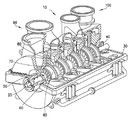
도 1을 참조하면, 종래의 디자인에 따른 다중 스테이지 원심 유동 터보기계(centrifugal-flow turbomachine)(10)가 도시된다. 일부 응용에서, 단일 스테이지가 활용될 수 있다. 이러한 터보기계(10)는 전반적으로 한 쌍의 베어링(40)에 의해 하우징(30) 내에 회전 가능하게 지지되는 샤프트(20)를 포함한다. 도 1에 도시된 터보기계(10)는 작동 유체의 유체 압력을 점진적으로 증가시키기 위해 복수의 스테이지를 포함한다. 각 스테이지는 터보기계(10)의 종축(longitudinal axis)을 따라 연속적으로 배치되며, 스테이지 모두는 동일한 원리로 작동하는 유사한 부품을 가질 수 있거나 가지지 않을 수 있다.Referring to FIG. 1, a multi-stage centrifugal-
도 1을 계속 참조하면, 임펠러(impeller)(50)는 결국 샤프트(20)에 부착되는 임펠러 허브(70)에 둘레방향으로 배치되고 부착되는 복수의 회전 블레이드(60)를 포함한다. 블레이드(60)는 커버 디스크(65)에 선택적으로 부착될 수 있다. 복수의 임펠러(50)는 샤프트(20)의 축방향 길이(axial length)를 따라 다중 스테이지 내에서 이격될 수 있다. 회전 블레이드(60)가 임펠러 허브(70)와 함께 샤프트(20)의 회전에 따라 회전하도록, 회전 블레이드(60)가 임펠러 허브(70)에 고정되게 결합된다. 회전 블레이드(60)가 정지형 튜브형 케이싱(stationary tubular casing)에 부착된 복수의 정지형 베인(stationary vane) 또는 스테이터(80)의 하류측에서 회전한다. 혼합 기체와 같은 작동 유체는 샤프트(20)의 축방향으로 터보기계(10)로 유입되고 배출된다. 작동 유체로부터의 에너지는 스테이터(80)에 대한 회전 블레이드(60)의 상대 운동을 일으킨다. 원심 압축기에서, 임펠러(50) 내의 회전 블레이드(60) 사이의 단면적이 입구단으로부터 배출단 쪽으로 감소하여, 작동 유체가 임펠러(50)를 횡단하여 통과하면서 압축된다.1, the
도 2를 참조하면, 혼합 기체와 같은 작동 유체가 터보기계(10)의 입구단(90)으로부터 출구단(100)으로 이동한다. 입구단(90)에 구비된 하나의 열의 스테이터(a row of stators)(80)가 작동 유체를 터보기계(10)의 출구단(100)에 구비된 하나의 열의 회전 블레이드(60) 내로 전달(channel)한다. 스테이터(80)는 작동 유체를 회전 블레이드(60)로 전달하기 위해 케이싱 내에서 연장된다. 스테이터(80)는 케이싱의 둘레 주위에서 개별 스트럿 사이에서 등간격으로 둘레방향으로 이격된다. 디퓨저(diffuser)(110)는 회전 블레이드(60)로부터 나오는 유체 유동을 균일화하기 위해 회전 블레이드(60)의 출구에 구비된다. 디퓨저(110)는 케이싱 내에서 연장되는 복수의 디퓨저 베인(120)을 선택적으로 갖는다. 디퓨저 블레이드(120)는 디퓨저 케이싱의 둘레 주위에서 개별 디퓨저 블레이드(120) 사이에서 등간격으로 둘레방향으로 이격된다. 다중 스테이지 터보기계(10)에서, 작동 유체를 다음의 연속적인 스테이지의 회전 블레이드(60)로 전달하기 위해, 복수의 리턴 채널 베인(125)이 터보기계(10)의 출구단(100)에 구비된다. 이러한 실시예에서, 리턴 채널 베인(125)은 터보기계(10)의 제1 스테이지로부터 스테이터(80)의 기능을 제공한다. 다중 스테이지 터보기계 내의 최후의 임펠러는 통상적으로 디퓨저 베인을 구비하거나 구비하지 않는 디퓨저만을 갖는다. 최후 디퓨저는 배출관에 연결되는 출구 플랜지를 갖는 배출 케이싱(벌류트(volute))으로 작동 유체의 유동을 전달한다. 단일 스테이지 실시예에서, 터보기계(10)는 입구단(90)에서의 스테이터(80)와, 출구단(100)에서의 디퓨저(110)를 포함한다.Referring to FIG. 2, a working fluid such as a mixed gas is transferred from the
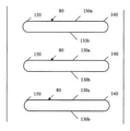
도 3를 참조하면, 복수의 스테이터(80)의 개략도가 도시된다. 각 스테이터(80)는 실질적으로 서로 평행하게 배향되는 한 쌍의 대향하는 종방향 표면(longitudinal surfaces)(130a, 130b)을 갖는다. 스테이터(80)는 바람직하게는 터보기계(10)의 종축에 대하여 동일한 각도로 배향(orient)된다. 각 스테이터(80)는, 하류측 끝단에 구비되는 후행 에지(trailing edge)(140)와 상류측 끝단에 구비되는 선행 에지(leading edge)(150)를 갖는다. 각 스테이터(80)의 후행 에지(140)는 인접한 스테이터(80)의 후행 에지(140)와 동일한 형상을 갖는다. 예를 들면, 후행 에지(140)는 둥근 지점(rounded point)에서 끝나는 뾰족한 프로파일(pointed profile)을 가질 수 있다. 마찬가지로, 각 스테이터(80)의 선행 에지(150)는 후행 에지(140)에 대응하는 형상을 가질 수 있다. 각 디퓨저 블레이드(120)(미도시)의 선행 에지(150)는 바람직하게는 후행 에지(140)와 동일하게 형성된다. 예를 들면, 스테이터(80)의 후행 에지(140)와 마찬가지로, 디퓨저 블레이드(120)의 선행 에지는 둥근 지점에서 끝나는 뾰족한 프로파일을 가질 수 있다.Referring to Fig. 3, a schematic view of a plurality of
터보기계를 설계하는 데에 있어 중요한 관심사는 터보기계의 작동 범위 전체에서 회전 블레이드 및 허브의 진동을 제어하는 것이다. 터보기계 내의 회전 블레이드 및 디스크는, a) 상류측 스테이터 스트럿(strut) 및/또는 베인 후류(vane wake) 및 하류측 스트럿 및 베인과의 퍼텐셜 유동(potential flow) 상호 작용, b) 불균일한 둘레방향 압력 분포에 의해 형성되는 유동 흐름 내의 다른 이질성(inhomogeneities), c) 회전 블레이드 통과 진동수(passing frequency)에서의 음향 파동(acoustic pulsation), 및/또는 d) 정지형 베인으로부터 발산하는 와류에 의해 공진 진동으로 여기되며(excited), 결국, 케이싱 내에서의 기체의 동시 발생적인 음향 공진(acoustic resonance)을 초래한다. 예를 들면, 스핀 모드(spinning mode)를 제공하는 베인으로부터 반사되는 블레이드 통과 진동수를 갖는 음파로 인해 Tyler/Sofrin 모드가 발생할 수 있다(Tyler, J. M., 및 Sofrin, T. G., 1962, "Axial Flow Compressor Noise Studies", SAE Transactions, Vol.70, pp.309-332. 참조). 음향 파동은 임펠러로부터 더 뒤로 설정된 스테이터 스트럿으로부터 상이하게 반사하며, 스핀 모드의 효과적인 진폭을 감소시킨다. 예를 들면, 15개의 회전 블레이드 및 20개의 스테이터 스트럿을 갖는 임펠러에서, 5개 직경 스핀 모드(5-diameter spinning mode)가 존재한다. 5개 직경 구조 모드(5-diameter structural mode)는 회전 속도의 20배와 동일하며, 파의 반사(wave reflection)가 위상 상쇄(phase cancellation)를 유발할 수 있으므로 음파 길이(acoustic wave length)의 약 이분의 일의 하류측에 스테이터 스트럿의 절반부를 설정하는 것에 의해, 블레이드 여기(blade excitation)가 낮아질 수 있다.An important concern in designing turbo machines is to control the vibrations of the rotating blades and hubs throughout the operating range of the turbo machine. The rotating blades and discs in the turbomachine are characterized by a) potential flow interaction with upstream stator struts and / or vane wakes and downstream struts and vanes, b) non-uniform circumferential direction Other inhomogeneities in the flow flow formed by the pressure distribution, c) acoustic pulsation at a rotating blade passing frequency, and / or d) resonant vibration by vortex emanating from the stationary vane Is excited and eventually results in the simultaneous acoustic resonance of the gas in the casing. For example, a Tyler / Sofrin mode can occur due to a sound wave having a blade pass frequency that reflects from a vane providing a spinning mode (Tyler, JM, and Sofrin, TG, 1962, "Axial Flow Compressor Noise Studies ", SAE Transactions, Vol. 70, pp. 309-332). The acoustic waves reflect differently from the stator struts set back from the impeller and reduce the effective amplitude of the spin mode. For example, in an impeller with 15 rotating blades and 20 stator struts, there is a 5-diameter spinning mode. The 5-diameter structural mode is equal to 20 times the rotational speed and the wave reflection can cause phase cancellation, so about half of the acoustic wave length By setting a half of the stator strut on the downstream side of the work of the blade excitation, the blade excitation can be lowered.
이러한 여기는 주기적인 응력(cyclic stress)을 초래하여, 회전 블레이드, 허브 또는 커버에서의 임펠러 내의 잠재적인 고 사이클 피로 및 고장(high cycle fatigue and failure)을 유발한다. 블레이드 모드 진동수(blade modal frequency)가 블레이드에 의해 나타나는 유동 이질성(flow inhomogeneity)의 조화수(harmonic number)를 곱한 샤프트 회전 진동수에 대응할 때, 임펠러 부품은 큰 진폭으로 여기될 수 있다. 통상적으로, 고 사이클 피로를 유발하기에 충분히 큰 진폭을 갖는 공진의 수가 제한된다. 재료의 무한한 내구 강도가 깨지는 경우에만 피로로부터의 손상율이 발생하므로, 진동 진폭에서 크지 않은 감소가 종종 블레이드 및 디스크 수명에 대한 제한 요인으로서의 고 사이클 피로를 제거할 수 있다.This excitation causes cyclic stresses, resulting in potential high cycle fatigue and failure in the impeller at the rotating blade, hub or cover. When the blade modal frequency corresponds to the shaft rotational frequency multiplied by the harmonic number of flow inhomogeneity exhibited by the blade, the impeller component can be excited with a large amplitude. Typically, the number of resonances with amplitudes large enough to cause high cycle fatigue is limited. Since a damage rate from fatigue occurs only when the infinite durability strength of the material is broken, a small reduction in vibration amplitude can often eliminate high cycle fatigue as a limiting factor for blade and disk life.
이러한 문제를 극복하기 위한 하나의 현재의 관행은, 공진에 직면할 때 속도를 신속하게 변경하는 것에 의해 공진 진동수에서의 작동을 방지하여, 작동 중 블레이드에 누적되는 피로 사이클(fatigue cycle)의 수를 최소화하는 것이다. 진동 사이클(vibration cycle)의 수가 최소화된 경우, 하류측 후류, 음향 파동, 유동 불균일성 또는 와류 발산(vortex shedding)이 아닌 메커니즘(mechanism)에 의해 블레이드 고장이 제어된다. 그러나, 이러한 관행은 터보기계의 작동에 바람직하지 않은 제한을 준다.One current practice to overcome this problem is to prevent the resonance frequency from operating by rapidly changing the speed in the face of resonance, thereby increasing the number of fatigue cycles accumulated in the blade during operation To minimize it. When the number of vibration cycles is minimized, the blade failure is controlled by a mechanism other than downstream wake, acoustic wave, flow non-uniformity or vortex shedding. However, this practice places undesirable limitations on the operation of the turbomachine.
현재의 다른 접근법은 장애물(obstructions) 뒤에서의 저속 후류 내로 공기를 직접 분사하는 것에 의해 유동장(flow field) 내에서의 공간적인 변동(spatial variation)을 감소시키는 것이다(Rao, N. M., Feng, J., Burdisso, R. A, 및 Ng, W. F., "Active Flow Control to Reduce Fan Blade Vibration 및 Noise", 5.sup.th AIAA/CEAS Aeroacoustic Conference, American Institute of Aeronautics 및 Astronautics, May 10-12, 1999). 이러한 접근법은 상대적으로 큰 양으로 압축기로부터의 공기 또는 추가적인 외부 공기원으로부터의 공기를 사용할 것을 필요로 한다. 압축기 공기의 사용은 성능에 유해한 영향을 미친다. 별도의 공기 공급부를 추가하는 것은 중량을 증가시키고 동력을 필요로 한다. 두 방법은 성능에 유해한 영향을 미친다. 또한, 후류 주입(wake filling)은 유동 장애물(flow obstruction)의 하류측으로부터의 두부파(bow wave)로 인한 모드 여기(modal excitation)를 해결하지 않는다.Another current approach is to reduce spatial variations in the flow field by direct injection of air into the low velocity wakes behind the obstructions (Rao, NM, Feng, J., Burdisso, R. A, and Ng, WF, "Active Flow Control to Reduce Fan Blade Vibration and Noise," 5th AIAA / CEAS Aeroacoustic Conference, American Institute of Aeronautics and Astronautics, May 10-12, 1999). This approach requires the use of air from a compressor or air from an additional external air source in a relatively large amount. The use of compressor air has a detrimental effect on performance. Adding a separate air supply increases weight and requires power. Both methods have a detrimental effect on performance. Also, wake filling does not address modal excitation due to bow waves from the downstream side of the flow obstruction.
종래 기술에서, 회전 블레이드의 진동 진폭을 감소시키고/시키거나 소음 감소를 제공하기 위해 다수의 접근법이 제시되었다. Kuhnel 등에게 부여된 미국 출원 공개 번호 2007/0274826는 압축기 임펠러용 디퓨저를 개시한다. Kuhnel 등의 공보의 도 1은, 각각 두 개의 부품 블레이드로 형성되는 가이드 블레이드를 포함하는 디퓨저 구조를 개시한다. 제1 부품 블레이드는 입구 에지를 가지며, 제2 부품 블레이드는 다른 입구 에지로부터 뒤로 단차진(stepped) 입구 에지를 갖는다. 도 2는 제3 부품 블레이드가 부품 블레이드들 사이에 구비되는 다른 실시예를 도시한다. 단차진 입구 에지는 소음 감소를 위해 구비된다.In the prior art, a number of approaches have been proposed to reduce the vibration amplitude of the rotating blades and / or to provide noise reduction. U.S. Patent Application Publication No. 2007/0274826 to Kuhnel et al. Discloses a diffuser for a compressor impeller. 1 of Kuhnel et al. Discloses a diffuser structure comprising guide blades each formed of two component blades. The first component blade has an inlet edge and the second component blade has a stepped inlet edge back from the other inlet edge. Figure 2 shows another embodiment in which a third component blade is provided between the component blades. The stepped entrance edge is provided for noise reduction.
Barton 등에게 부여된 미국 특허 번호 7,189,059는 임펠러 주위에 위치되는 입구 쉬라우드(shroud)를 갖는 압축기를 개시한다. 도 2에 도시된 바와 같이, 쉬라우드는 복수의 이격된 베인 또는 스트럿 선단(tip)을 갖는 스트럿을 포함한다. 도 6에 도시된 바와 같이, 스트럿은 제1 단 및 스트럿 선단 사이의 두께가 다르게 구성된다. 스트럿의 고유 진동수(natural frequency)를 증가시키기 위한 스트럿 제1 단 및 스트럿 선단 사이의 선형 테이퍼(linear taper)로서, 두께의 변화가 구현된다.U.S. Patent No. 7,189,059 to Barton et al. Discloses a compressor having an inlet shroud positioned around an impeller. As shown in Figure 2, the shroud includes a strut having a plurality of spaced vanes or strut tips. As shown in Fig. 6, the strut has a different thickness between the first end and the strut tip. A change in thickness is implemented as a linear taper between the strut first end and the strut tip to increase the natural frequency of the strut.
Crall 등에게 부여된 미국 특허 번호 6,439,838는 진동 여기를 감소시키기 위해 축류 터보기계의 베인의 가변 둘레방향 간격의 사용을 개시한다.U.S. Patent No. 6,439,838 to Crall et al. Discloses the use of a variable circumferential spacing of vanes in an axial turbo machine to reduce vibration excitation.
Clark, J., "Design Strategies to Mitigate Unsteady Forcing (Preprint)", AFRL-RZ-WP-TP-2008-2112은 수평 분할 구성을 갖는 기계의 상측 및 하측의 두 개의 절반부에서 상이한 개수의 정지형 베인을 사용하는 것을 포함하는 회전 블레이드에 대한 여기를 감소시키는 데에 사용되는 종래 기술을 제시한다.AFRL-RZ-WP-TP-2008-2112 has a different number of stationary vanes in two halves, upper and lower, of a machine having a horizontal split configuration, as described in Clark, J., "Design Strategies to Mitigate Unsteady Forcing Which is used to reduce excitation on a rotating blade, including using a rotating blade.
그러나, 종래 기술 디자인 중 어느 것도, 음압 파동(acoustic pressure pulsation) 및 회전 블레이드로의 직접적인 압력 부하를 감소시킬 뿐만 아니라 유동 흐름 내의 연속적인 후류를 불균일화하고 베인으로부터 발산하는 와류의 효과를 감소시키기는 것에 의해 로터 블레이드 여기를 감소시키도록 구성되는 정지형 베인 장치와 관련되지 않는다.However, none of the prior art designs reduce acoustic pressure pulsation and direct pressure loading into the rotating blades, as well as to reduce the effect of vortexing that diverges the continuous wake in the flow stream and emanates from the vane Lt; RTI ID = 0.0 > vane < / RTI >
일 실시예에 따르면, 작동 유체를 터보기계의 입구단으로부터 출구단으로 안내하기 위해 정지형 베인 장치가 구비된다. 정지형 베인 장치는 케이싱의 둘레 주위에서 둘레방향 간격으로 케이싱으로부터 반경방향 내측으로 연장되는 적어도 하나의 열의 복수의 정지형 베인을 포함한다. 각 정지형 베인은 후행 에지에 반대되는 선행 에지와, 선행 에지 및 후행 에지 사이에서 연장되는 대향하는 종방향 표면을 갖는다. 정지형 베인의 제1 부의 후행 에지는 제1 단 프로파일(end profile)을 가질 수 있고, 정지형 베인의 제2 부의 후행 에지는 제1 단 프로파일과 상이한 제2 단 프로파일을 가질 수 있다. 후행 에지의 하류측에서의 근본적인 후류 통과 진동수를 최소화하기 위해, 제1 단 프로파일을 갖는 정지형 베인이 제2 단 프로파일을 갖는 정지형 베인 사이에 구비되도록, 정지형 베인이 배치될 수 있다.According to one embodiment, a stationary vane device is provided for guiding the working fluid from the inlet end to the outlet end of the turbomachine. The stationary vane device includes a plurality of stationary vanes of at least one row extending radially inwardly from the casing at circumferential spacings around the circumference of the casing. Each stationary vane has a leading edge opposite the trailing edge and an opposing longitudinal surface extending between the leading edge and the trailing edge. The trailing edge of the first portion of the stationary vane may have a first end profile and the trailing edge of the second portion of the stationary vane may have a second end profile that is different from the first end profile. To minimize the fundamental wake pass frequency on the downstream side of the trailing edge, a stationary vane with a first stage profile may be disposed between stationary vanes with a second stage profile.
다른 실시예에 따르면, 제1 단 프로파일은 실질적으로 둥근 끝단(rounded end)을 가질 수 있고, 제2 단 프로파일은 스트럿의 대향하는 종방향 표면에 대하여 각이 진 테이퍼진 끝단(tapered end)을 가질 수 있다. 다른 실시예에서, 제1 단 프로파일은 스트럿의 대향하는 종방향 표면에 대하여 제1 방향으로 각이 진 테이퍼진 끝단을 가질 수 있으며, 제2 단 프로파일은 대향하는 종방향 표면에 대하여 제2 방향으로 각이 진 테이퍼진 끝단을 가질 수 있다.According to another embodiment, the first end profile may have a substantially rounded end and the second end profile may have an angled tapered end relative to the opposite longitudinal surface of the strut . In another embodiment, the first end profile may have a tapered end angled in a first direction relative to an opposing longitudinal surface of the strut, and the second end profile may have a tapered end that is angled in a second direction It can have an angled tapered end.
추가적인 실시예에 따르면, 복수의 정지형 베인은 터보기계의 입구단에 구비될 수 있다. 정지형 베인은 복수의 정지형 베인으로부터 하류측의 회전 블레이드의 일 열로 작동 유체를 향하게 하도록 구성될 수 있다. 복수의 정지형 베인은 케이싱을 통과하여 연장되는 종축을 중심으로 서로에 대하여 등거리로 케이싱의 둘레 주위에서 둘레방향으로 이격될 수 있다. 정지형 베인은 케이싱을 통과하여 연장되는 종축에 대하여 동일한 각도 위치에서 배향될 수 있다. 일 실시예에서, 복수의 정지형 베인은 선형 프로파일을 가질 수 있다. 다른 실시예에서, 복수의 정지형 베인은 유선형 프로파일(streamlined profile)을 가질 수 있다.According to a further embodiment, a plurality of stationary vanes may be provided at the inlet end of the turbomachine. The stationary vane may be configured to direct the working fluid from the plurality of stationary vanes to a row of rotating blades downstream. The plurality of stationary vanes may be circumferentially spaced around the circumference of the casing equidistantly with respect to each other about a longitudinal axis extending through the casing. The stationary vane may be oriented at the same angular position relative to the longitudinal axis extending through the casing. In one embodiment, the plurality of stationary vanes may have a linear profile. In another embodiment, the plurality of stationary vanes may have a streamlined profile.
또 다른 실시예에서, 복수의 회전 블레이드를 갖는 로터가 복수의 정지형 베인으로부터 하류측에 구비될 수 있어, 복수의 정지형 베인이 작동 유체를 복수의 회전 블레이드로 향하게 하도록 구성된다. 또한, 복수의 디퓨저 베인을 선택적으로 갖는 디퓨저는 케이싱의 둘레 주위에서 둘레방향 간격으로 케이싱으로부터 반경방향 내측으로 연장되는 복수의 회전 블레이드의 하류측에 구비될 수 있다. 각 디퓨저 베인은, 구비될 때, 후행 에지에 반대되는 선행 에지와, 선행 에지 및 후행 에지 사이에서 연장되는 대향하는 종방향 표면을 가질 수 있다. 디퓨저 베인의 제1 부(portion)의 선행 에지는 제1 단 프로파일을 가질 수 있고, 디퓨저 베인의 제2 부의 선행 에지는 제1 단 프로파일과 상이한 제2 단 프로파일을 가질 수 있다. 디퓨저 베인은 제1 단 프로파일을 갖는 디퓨저 베인이 제2 단 프로파일을 갖는 디퓨저 베인에 인접하게 구비되도록 배치될 수 있다.In another embodiment, a rotor having a plurality of rotating blades may be provided downstream from the plurality of stationary vanes, such that the plurality of stationary vanes direct the working fluid to the plurality of rotating blades. The diffuser optionally having a plurality of diffuser vanes may be provided on a downstream side of a plurality of rotating blades extending radially inwardly from the casing at circumferential intervals around the circumference of the casing. Each diffuser vane, when provided, may have a leading edge opposite the trailing edge and an opposing longitudinal surface extending between the leading edge and the trailing edge. The leading edge of the first portion of the diffuser vane may have a first end profile and the leading edge of the second portion of the diffuser vane may have a second end profile that is different from the first end profile. The diffuser vane may be positioned such that the diffuser vane having the first stage profile is adjacent to the diffuser vane having the second stage profile.
추가적인 실시예에 따르면, 복수의 디퓨저 베인은 케이싱을 통과하여 연장되는 종축을 중심으로 서로에 대하여 등거리로 케이싱의 둘레 주위에서 둘레방향으로 이격될 수 있다. 디퓨저 베인은 케이싱을 통과하여 연장되는 종축에 대하여 동일한 각도 위치에서 배향될 수 있다. 일 실시예에서, 복수의 디퓨저 베인은 선형 프로파일을 가질 수 있다. 다른 실시예에서, 디퓨저 베인은 유선형 프로파일을 가질 수 있다.According to a further embodiment, the plurality of diffuser vanes may be circumferentially spaced around the circumference of the casing equidistantly with respect to each other about a longitudinal axis extending through the casing. The diffuser vane may be oriented at the same angular position relative to the longitudinal axis extending through the casing. In one embodiment, the plurality of diffuser vanes may have a linear profile. In another embodiment, the diffuser vane may have a streamlined profile.
다른 실시예에 따르면, 터보기계는 케이싱의 종축을 따라 출구단에 반대되는 입구단을 갖는 케이싱을 가질 수 있다. 샤프트 조립체는 케이싱 내에 구비되며 입구단 및 출구단 사이에서 연장된다. 뿐만 아니라, 복수의 회전 블레이드를 갖는 로터가 샤프트 조립체로부터 반경방향 외측으로 연장될 수 있다. 또한, 정지형 베인 장치가 로터의 상류측에 구비된다. 정지형 베인 장치는 케이싱의 둘레 주위에서 둘레방향 간격으로 케이싱으로부터 반경방향 내측으로 연장되는 적어도 하나의 열의 복수의 정지형 베인을 포함할 수 있다. 각 정지형 베인은 후행 에지에 반대되는 선행 에지와, 선행 에지 및 후행 에지 사이에서 연장되는 대향하는 종방향 표면을 가질 수 있다. 정지형 베인의 제1 부의 후행 에지는 제1 단 프로파일을 가질 수 있고, 정지형 베인의 제2 부의 후행 에지는 제1 단 프로파일과 상이한 제2 단 프로파일을 가질 수 있다. 정지형 베인은 제1 단 프로파일을 갖는 정지형 베인이 제2 단 프로파일을 갖는 정지형 베인에 인접하게 구비되도록 배치될 수 있다.According to another embodiment, the turbomachine may have a casing having an inlet end opposite the outlet end along the longitudinal axis of the casing. The shaft assembly is provided in the casing and extends between the inlet end and the outlet end. In addition, a rotor having a plurality of rotating blades can extend radially outward from the shaft assembly. Further, a stationary vane device is provided on the upstream side of the rotor. The stationary vane device may include a plurality of stationary vanes of at least one row extending radially inwardly from the casing at circumferential spacings around the circumference of the casing. Each stationary vane may have a leading edge opposite the trailing edge and an opposing longitudinal surface extending between the leading edge and the trailing edge. The trailing edge of the first portion of the stationary vane may have a first end profile and the trailing edge of the second portion of the stationary vane may have a second end profile that is different from the first end profile. The stationary vane may be arranged such that the stationary vane with the first stage profile is adjacent to the stationary vane with the second stage profile.
다른 실시예에 따르면, 복수의 정지형 베인은 터보기계의 입구단에 구비될 수 있고, 작동 유체를 복수의 정지형 베인으로부터 하류측의 회전 블레이드의 열로 향하게 하도록 구성될 수 있다. 이 실시예에서, 복수의 정지형 베인은 케이싱을 통과하여 연장되는 종축에 대하여 동일한 각도 위치에서 배향될 수 있다. 일 실시예에 따르면, 복수의 정지형 베인은 선형 프로파일을 가질 수 있다. 대안적으로, 복수의 정지형 베인은 유선형 프로파일을 가질 수 있다. 또한, 복수의 디퓨저 베인은 케이싱의 둘레 주위에서 둘레방향 간격으로 케이싱으로부터 반경방향 내측으로 연장되는 복수의 회전 블레이드의 하류측에 구비될 수 있다. 각 디퓨저 베인은 후행 에지에 반대되는 선행 에지와, 선행 에지 및 후행 에지 사이에서 연장되는 대향하는 종방향 표면을 가질 수 있다. 디퓨저 베인의 제1 부의 선행 에지는 제1 단 프로파일을 가질 수 있고, 디퓨저 베인의 제2 부의 선행 에지는 제1 단 프로파일과 상이한 제2 단 프로파일을 가질 수 있다. 디퓨저 베인은 제1 단 프로파일을 갖는 디퓨저 베인이 제2 단 프로파일을 갖는 디퓨저 베인에 인접하게 구비되도록 배치될 수 있다.According to another embodiment, a plurality of stationary vanes may be provided at the inlet end of the turbomachine and configured to direct the working fluid from the plurality of stationary vanes to the row of rotating blades downstream. In this embodiment, the plurality of stationary vanes may be oriented at the same angular position relative to the longitudinal axis extending through the casing. According to one embodiment, the plurality of stationary vanes may have a linear profile. Alternatively, the plurality of stationary vanes may have a streamlined profile. The plurality of diffuser vanes may be provided on the downstream side of the plurality of rotating blades extending radially inwardly from the casing at circumferential intervals around the circumference of the casing. Each diffuser vane may have a leading edge opposite the trailing edge and an opposing longitudinal surface extending between the leading edge and the trailing edge. The leading edge of the first part of the diffuser vane may have a first end profile and the leading edge of the second part of the diffuser vane may have a second end profile that is different from the first end profile. The diffuser vane may be positioned such that the diffuser vane having the first stage profile is adjacent to the diffuser vane having the second stage profile.
구조의 연관된 요소 및 부품의 조합의 작동 방법 및 기능 및 제조의 경제성뿐만 아니라 터보기계의 이러한 특징 및 특성과 다른 특징 및 특성은, 그 모두가 본 명세서의 일부를 형성하는, 다양한 도면에서 대응하는 부분에 동일한 도면 부호가 지정된 첨부된 도면을 참조한 후술하는 설명 및 첨부된 청구범위를 고려하면, 더 명백해질 것이다. 그러나, 도면은 도시 및 설명만을 위한 것이며 본 발명의 제한을 정의하는 것으로 의도되지 않는다는 것이 명확히 이해될 것이다. 본 명세서 및 청구범위에 사용되는 바와 같이, 단수형 "a", "an", 및 "the"는 문맥이 명확하게 달리 표시하지 않는다면 복수형을 포함한다.These and other features and characteristics of the turbomachine as well as the manner and functioning of the operation and function of the associated element and combination of components of the structure, as well as the economics of manufacture, will be apparent to those skilled in the art, Will be more apparent in light of the following description taken in conjunction with the accompanying drawings in which like reference numerals designate like elements throughout, and in which: FIG. However, it will be clearly understood that the drawings are for purposes of illustration only and are not intended to define limitations of the invention. As used in this specification and the claims, the singular forms "a "," an ", and "the" include plural forms unless the context clearly dictates otherwise.
도 1은 종래 기술 실시예에 따른 다중 스테이지 원심 유동 터보기계의 부분 절개 사시도이다.
도 2는 도 1에 도시된 터보기계의 일 스테이지의 개략적인 단면도이다.
도 3은 종래 기술 실시예에 따른 복수의 스테이터의 개략도이다.
도 4는 본 발명의 일 실시예에 따른 다중 스테이지 원심 유동 터보기계의 일 스테이지의 종축에 따른 개략적인 단면도이다.
도 5a 내지 도 5c는 본 발명의 두 실시예에 따른 정지형 베인 장치의 개략도를 도시한다.1 is a partially cutaway perspective view of a multi-stage centrifugal flow turbomachine according to the prior art.
2 is a schematic cross-sectional view of one stage of the turbomachine shown in Fig.
3 is a schematic view of a plurality of stator in accordance with the prior art embodiment.
4 is a schematic cross-sectional view along the longitudinal axis of one stage of a multi-stage centrifugal flow turbomachine according to one embodiment of the present invention.
Figures 5A-5C show schematic views of a stationary vane apparatus according to two embodiments of the present invention.
이하, 설명을 위해, "상측(upper)", "하측(lower)", "우측(right)", "좌측(left)", "수직(vertical)", "수평(horizontal)", "상부(top)", "저부(bottom)", "횡방향(lateral)", "종방향(longitudinal)"이라는 용어 및 그 파생어는, 도면에서 배향된 것과 같이 본 발명에 연관된다. 그러나, 이와 달리 명확히 특정된 경우를 제외하고, 본 발명은 대안적인 변형예 및 단계 순서를 상정할 수 있는 것으로 이해될 것이다. 또한, 첨부된 도면에 도시되고 후술하는 명세서에서 설명되는 구체적인 장치 및 과정은 단순히 본 발명의 예시적인 실시예인 것으로 이해될 것이다. 그러므로, 본원에 개시된 실시예와 연관된 구체적인 치수 및 다른 물리적인 특징은 한정되는 것으로 여겨지지 않는다.Hereinafter, for the purpose of explanation, the terms "upper," "lower," "right," "left," "vertical," " top "," bottom "," lateral "," longitudinal "and derivatives thereof are related to the present invention as directed in the drawings. It will be appreciated, however, that the invention can assume alternative variations and step sequences, except where otherwise explicitly specified. It is also to be understood that the specific apparatus and process illustrated in the accompanying drawings and described in the following description are merely exemplary embodiments of the present invention. Therefore, the specific dimensions and other physical characteristics associated with the embodiments disclosed herein are not considered to be limiting.
상술한 바와 같이, 종래의 터보기계(10) 내의 회전 블레이드(60)는, a) 상류측 스테이터 스트럿 및/또는 베인 후류(wake) 및 하류측 스트럿 및 베인과의 퍼텐셜 유동(potential flow) 상호 작용, b) 불균일한 둘레방향 압력 분포에 의해 형성되는 유동 흐름 내의 다른 이질성, c) 회전 블레이드 통과 진동수(passing frequency)에서의 음향 파동(acoustic pulsation), 및/또는 d) 스트럿 또는 베인으로부터 발산하는 와류에 의해 공진 진동으로 여기되며(excited), 결국, 케이싱 내에서의 기체의 동시 발생적인 음향 공진을 초래한다. 블레이드 모드 진동수가 회전 블레이드(60)에 의해 나타나는 유동 이질성의 조화수(harmonic number)를 곱한 샤프트 회전 진동수에 대응할 때, 회전 블레이드(60)는 큰 진폭으로 여기될 수 있다.As described above, the
종래 기술의 이러한 결함을 극복하기 위해, 본 발명은, 파괴력을 감소시키고 적용 범위를 증가시키도록 회전 블레이드 내로의 유동을 균일화하도록 구성된 정지형 베인 장치를 제공한다. 본 발명은, 정지형 베인으로부터 발산되는(shed-off) 와류의 효과를 감소시킬 뿐만 아니라 유동 및 음향 파동 모두에 대한 기체 유동 흐름을 균일화함으로써 로터 블레이드 및/또는 디스크 여기(excitation)를 감소시키도록 구성되는 정지형 베인 장치를 제공한다.In order to overcome this drawback of the prior art, the present invention provides a stationary vane device configured to equalize the flow into the rotating blade to reduce the destructive force and increase the coverage. The present invention provides a system and method for reducing rotor blade and / or disk excitation by reducing the effect of shed-off vortices from stationary vanes, as well as equalizing gas flow for both flow and acoustic waves And a stationary vane device.
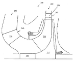
도 4를 참조하면, 터보기계(200)는, 스테이터 스트럿의 후행 에지에서 발산하는 와류로 인한 유동 흐름 내의 이질성에 의해 유발되는 공진 진동을 감소시키거나 제거하도록 구성되는 정지형 베인 장치를 포함한다. 도 4는 터보기계(200)의 단일 스테이지를 도시하고 있으나, 통상의 기술자는 도 4에 도시된 구체적인 부품이 다중 스테이지 원심 유동 압축기와 같은 다중 스테이지 터보기계에서의 사용에 용이하게 적용될 수 있음을 이해할 것이다.Referring to FIG. 4, the
도 4를 계속 참조하면, 터보기계(200)는 샤프트(220)와 회전 가능한 디스크(215) 주위에 둘레방향으로 배치되는 복수의 회전 블레이드(210)를 포함한다. 터보기계(200)가 다중 스테이지를 갖는 실시예(미도시)에서, 회전 블레이드(210)는 샤프트(220)의 축방향 길이를 따라 다중 스테이지 내에 배치된다. 다른 실시예에서, 회전 블레이드(210)가 샤프트(220)의 회전과 함께 회전하도록, 회전 블레이드(210)가 샤프트(220)에 고정되게 결합될 수 있다. 회전 블레이드(210)는 정지형 튜브형 케이싱(240)에 부착되는 복수의 정지형 베인(230)(즉, 정지형 베인 장치)에 인접하게 회전한다. 혼합 기체와 같은 작동 유체(working fluid)가 터보기계(200)의 입구단(250)으로부터 출구단(260)으로 이동한다. 입구단(250)에 구비된 하나의 열의 정지형 베인(230)이 작동 유체를 터보기계(200)의 출구단(260)에서의 하나의 열의 회전 블레이드(210) 내로 전달한다. 정지형 베인(230)의 개수는 회전 블레이드(210)의 개수에 대응할 수 있다. 대안적으로, 정지형 베인(230)의 개수는 회전 블레이드(210)의 개수에 비하여 많거나 적을 수 있다. 바람직하게는, 블레이드 모두가 원형 라인을 따라 동일 위상에서 진동할 때 원형 및 비틀림 모드(circular and torsional modes)를 제거하기 위해, 회전 블레이드(210)의 개수는 정지형 베인(230)과 동일하지 않다. 정지형 베인(230)은 짝수 개 또는 홀수 개의 개별 베인을 가질 수 있다. 공기역학적 우려로 인하여, 혼합을 향상시키고 베인으로부터 발산하는 와류의 효과를 감소시키기 위해, 정지형 베인(230)은 바람직하게는 회전 블레이드(210)에 근접하게 구비된다. 이러한 배치는 음압 파동 및 회전 블레이드(210)에 가해지는 직접적인 압력 부하를 감소시킨다.4, the
디퓨저(280)가, 선택적인 디퓨저 베인(270)과 함께, 회전 블레이드(210)로부터 나오는 유체 유동을 균일화하기 위해 회전 블레이드(210)의 출구에 구비된다. 디퓨저(280)가 바람직하게는 터보기계(200)의 출구단(260)에 구비된다. 각 디퓨저(280)는 선택적으로 그 다음의 연속적인 스테이지의 정지형 베인(230)으로 작동 유체를 전달하기 위해 케이싱을 횡단하여 연장되는 하나 이상의 디퓨저 베인(270)을 갖는다. 디퓨저 베인(270)은 바람직하게는 디퓨저 케이싱의 둘레 주위에서 동등하게 이격된다.A
정지형 베인(230)은 작동 유체를 회전 블레이드(210)로 향하게 하기 위해 정지형 케이싱(240)의 내부를 횡단하여 연장된다. 정지형 베인(230)은 바람직한 공기역학적 성능을 확보하기 위해 정지형 케이싱(240)의 둘레 주위의 개별 베인 사이에서 동일한 간격으로 둘레방향으로 이격된다. 종래의 스트럿의 후행 에지의 하류측에서의 근본적인 후류 통과 진동수의 생성으로 이어지는 종래 기술 디자인의 결함을 극복하기 위해, 본 발명은 터보기계가 다양한 작동 속도에 걸쳐 작동됨에 따라 회전 블레이드의 하나 이상의 공진 진공 모드의 진동 여기(vibratory excitation)를 감소시키도록 구성되는 정지형 베인 장치를 포함한다.The
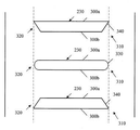
도 5a 내지 도 5c를 참조하면, 정지형 베인 장치의 다양한 구성이 본 발명의 복수의 실시예에 따라 도시된다. 도 5a 내지 도 5c는 각각 복수의 정지형 베인(230)의 개략도를 도시한다. 각 실시예에서, 정지형 베인(230)은 한 쌍의 대향하는 종방향 표면(300a, 300b)을 갖는다. 도 5a 내지 도 5c에 도시된 바와 같이, 각 정지형 베인(230)의 대향하는 종방향 표면(300a, 300b)은 실질적으로 선형이며 실질적으로 서로 평행하다. 대안적인 실시예에서, 각 정지형 베인(230)의 대향하는 종방향 표면(300a, 300b)은 특정 공기역학적 프로파일을 갖도록 유선형일 수 있다.Referring to Figures 5A-5C, various configurations of stationary vane devices are shown in accordance with multiple embodiments of the present invention. Figures 5A-5C show schematic views of a plurality of
각 정지형 베인(230)은, 하류측 끝단에 구비되는 후행 에지(310)와 상류측 끝단에 구비되는 선행 에지(320)를 갖는다. 각 정지형 베인의 후행 에지가 각 인접하는 후행 에지와 동일한 형상을 갖는 종래 기술 디자인에 대조적으로, 도 5a 내지 도 5c에 도시된 정지형 베인(230)은 회전 블레이드(210)의 하나 이상의 공진 진동 모드의 진동 여기를 감소시키기 위해 스테이터 후류에 의해 발생되는 힘을 감소시키거나 상쇄하는 수정된 디자인을 포함한다.Each
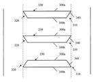
도 5a를 구체적으로 참조하면, 교호하는 패턴의 후행 에지(310) 및 선행 에지(320)를 갖는 정지형 베인(230)이 홀수 개의 정지형 베인(230)을 갖는 스테이터에 대하여 도시된다. 하나의 바람직한 비한정적 실시예에서, 정지형 베인(230)은 균일화된 후류 패턴을 교대로 만들기 위해 둘 또는 셋의 그룹으로 그룹화된다. 예를 들면, 도 5a에 나타낸 바와 같이 배치되는 21개의 정지형 베인(230)을 갖는 스테이터는 세 개의 정지형 베인 세트의 그룹의 반복하는 패턴을 갖는다. 정지형 베인(230)은 바람직하게는 인접하는 베인 사이에서 반경방향으로 동일하게 분리되어 위치된다. 또한, 정지형 베인(230) 모두가 정지형 케이싱(240) 내에서 동일한 종방향 위치에 배치됨으로써, 정지형 베인(230) 모두가 회전 블레이드(210)(도 5a에 도시되지 않음)로부터 동등하게 이격된다. 정지형 베인(230)은, 정지형 베인(230)의 제1 절반부가, 도 3에 도시된 정지형 베인(80)과 유사하게, 실질적으로 둥근 끝단(330)에서 종결하는 후행 에지(310) 및 선행 에지(320)를 갖도록, 배치된다. 도 5a에 도시된 정지형 베인 장치의 정지형 베인(230)의 제2 절반부는 테이퍼진 끝단(340)에서 종결하는 후행 에지(310) 및 선행 에지(320)를 갖는다. 둥근 끝단(330)을 갖는 각 정지형 베인(230)이 테이퍼진 끝단(340)을 갖는 정지형 베인(230) 사이에 위치되도록 두 타입의 정지형 베인(230)이 배치된다. 대향하는 종방향 표면(300a, 300b)에 대한 각도로 하나의 종방향 표면(300a, 300b)의 일부를 절단하는 것에 의해, 테이퍼진 끝단(340)이 형성된다. 각 정지형 베인(230)의 후행 에지(310) 및 선행 에지(320)는, 도 5a에 도시된 바와 같이, 동일 방향 또는 반대 방향으로 테이퍼지는 테이퍼진 끝단(340)을 가질 수 있다.5A, a
각 디퓨저 베인(미도시)의 선행 에지는 바람직하게는 유사한 방식으로 형성된다. 예를 들면, 각 디퓨저 베인의 선행 에지는 일부 디퓨저 베인이 실질적으로 둥근 선행 에지를 갖는 한편 나머지 디퓨저 베인은 테이퍼진 선행 에지를 갖는 교호하는 패턴을 가질 수 있다.The leading edge of each diffuser vane (not shown) is preferably formed in a similar manner. For example, the leading edge of each diffuser vane may have an alternating pattern with some diffuser vanes having a substantially rounded leading edge while the remaining diffuser vanes having a tapered leading edge.
도 5b를 구체적으로 참조하면, 교호하는 패턴의 후행 에지(310) 및 선행 에지(320)를 갖는 정지형 베인(230)이 짝수 개의 정지형 베인(230)을 갖는 스테이터에 대하여 도시된다. 도 5a에 도시된 실시예와 마찬가지로, 정지형 베인(230)은 균일화된 후류 패턴을 교대로 만들기 위해 둘 또는 셋의 그룹으로 그룹화된다. 예를 들면, 도 5b에 나타낸 바와 같이 배치되는 20개의 정지형 베인(230)을 갖는 스테이터는 두 개의 정지형 베인 쌍의 그룹의 반복하는 패턴을 갖는다. 정지형 베인(230)은 바람직하게는 인접하는 베인 사이에서 반경방향으로 동일하게 분리되어 위치된다. 또한, 정지형 베인(230)이 정지형 케이싱(240) 내에서 교호하는 오프셋 종방향 위치 내에 배치됨으로써, 일부 정지형 베인(230)이 다른 정지형 베인(230)에 비하여 회전 블레이드(210)(도 5a에 도시되지 않음)에 더 가깝다. 정지형 베인(230)은, 정지형 베인(230)의 제1 절반부(first half)가, 도 5a에 도시된 정지형 베인(230)과 유사하게, 실질적으로 둥근 끝단(330)에서 종결하는 후행 에지(310) 및 선행 에지(320)를 갖도록, 배치된다. 도 5a에 도시된 정지형 베인 장치와 마찬가지로, 도 5b에 도시된 정지형 베인 장치의 정지형 베인(230)의 제2 절반부는 테이퍼진 끝단(340)에서 종결하는 후행 에지(310) 및 선행 에지(320)를 갖는다. 둥근 끝단(330)을 갖는 각 정지형 베인(230)이 테이퍼진 끝단(340)을 갖는 정지형 베인(230) 사이에 위치되도록 두 타입의 정지형 베인(230)이 배치된다. 둥근 끝단(330)을 갖는 정지형 베인(230)은 테이퍼진 끝단(340)을 갖는 정지형 베인(230)에 대하여 종방향으로 뒤로 설정된다. 이러한 구성에서, 둥근 끝단(330)을 갖는 정지형 베인(230)은 테이퍼진 끝단(340)을 갖는 정지형 베인(230)에 비하여 회전 블레이드(210)(도 5b에 도시되지 않음)에 더 가깝게 위치된다. 대향하는 종방향 표면(300a, 300b)에 대한 각도로 하나의 종방향 표면(300a, 300b)의 일부를 절단하는 것에 의해, 테이퍼진 끝단(340)이 형성된다. 개별 정지형 베인(230)의 후행 에지(310) 및 선행 에지(320)는, 도 5b에 도시된 바와 같이, 동일 방향 또는 반대 방향으로 테이퍼지는 테이퍼진 끝단(340)을 가질 수 있다.Referring specifically to FIG. 5B, a
도 5c를 구체적으로 참조하면, 다른 실시예에 따라, 교호하는 패턴의 후행 에지(310) 및 선행 에지(320)를 갖는 정지형 베인(230)이 짝수 개의 정지형 베인(230)을 갖는 스테이터에 대하여 도시된다. 다른 실시예와 마찬가지로, 정지형 베인(230)은 균일화된 후류 패턴을 교대로 만들기 위해 둘 또는 셋의 그룹으로 그룹화된다. 예를 들면, 도 5c에 나타낸 바와 같이 배치되는 20개의 정지형 베인(230)을 갖는 스테이터는 두 개의 정지형 베인 쌍의 그룹의 반복하는 패턴을 갖는다. 정지형 베인(230)은 바람직하게는 인접하는 베인 사이에서 반경방향으로 동일하게 분리되어 위치된다. 또한, 정지형 베인(230) 모두가 정지형 케이싱(240) 내에서 동일한 종방향 위치에 배치됨으로써, 정지형 베인(230) 모두가 회전 블레이드(210)(도 5c에 도시되지 않음)로부터 동등하게 이격된다. 도 5c에 도시된 정지형 베인 장치의 정지형 베인(230) 모두는 테이퍼진 끝단(340)에서 종결하는 후행 에지(310) 및 선행 에지(320)를 갖는다. 대향하는 종방향 표면(300a, 300b)에 대한 각도로 하나의 종방향 표면(300a, 300b)의 일부를 절단하는 것에 의해, 테이퍼진 끝단(340)이 형성된다. 이 실시예에서, 테이퍼진 끝단(340)은 상호 반대하는 각도로 경사지게 배치된다. 다시 말하면, 정지형 베인(230)은 테이퍼진 끝단(340)이 인접하는 정지형 베인(230) 사이에서 교대로 절단되도록 배치된다. 마찬가지로, 각 디퓨저 베인(미도시)의 선행 에지는 바람직하게는 유사한 방식으로 형성된다. 예를 들면, 각 디퓨저 베인의 선행 에지는 디퓨저 베인이 상호 반대되는 테이퍼진 선행 에지를 갖는 교호하는 패턴을 가질 수 있다.5c, in accordance with another embodiment, a
상술한 정지형 베인 장치는 유동 흐름 내의 연속적인 후류를 불균일화하고(dehomogenizing) 정지형 베인(230)으로부터 발산되는 음향 파동 및 와류의 효과를 감소시키는 것에 의해 회전 블레이드(210) 및 디스크(215)의 여기를 감소시키도록 구성된다. 정지형 베인(230)의 후행 에지(310)의 하류측에서의 근본적인 후류 통과 진동수로의 여기의 생성이 최소화되며, 이에 의해, 터보기계가 다양한 작동 속도에 걸쳐 작동됨에 따라 회전 블레이드의 하나 이상의 공진 진동 모드의 진동 응답을 감소시킨다. 또한, 음향 여기에 대한 응답이 상술한 정지형 베인 장치에 의해 완화된다.The above-described stationary vane device is capable of dehomogenizing continuous wakes in the flow stream and thereby reducing the effect of acoustic waves and eddies emanating from
정지형 베인(230)으로부터 나오는 후류에 의해 발생되는 힘이 주어진 작동 속도에서 전체 로터에 대하여 서로 상쇄하는지 여부를 판단하기 위해, 로터 상의 회전 블레이드(210)의 개수가 회전 블레이드(210)와 상호 작용하는 정지형 베인(230)의 개수와 관련하여 고려된다. 예를 들면, 15개 블레이드의 임펠러의 5개 직경 모드와 같은 디스크(215) 또는 결합된 블레이드 구조 모드의 경우, 정지형 베인(230)으로부터 발산하는 여기 힘(exciting force)은, 10개 베인 또는 20개 베인의 스테이터를 제외하고, 정지형 베인 장치 모두에 대하여 상쇄한다. 고유 진동수가 10개 블레이드의 스테이터에서 작동 속도의 10배와 동일하다면, 또는 10개 블레이드 또는 20개 블레이드의 스테이터에서 구조적 진동수가 작동 속도의 20배와 동일하다면, 힘은 상쇄하지 않는다. 위상 상쇄(phase cancellation)가 달성될 수 없는 실시예를 나타내는 매개 변수 수학식이 아래에 제시된다.The number of
수학식 (1) 수학식 (2)Equation (1) Equation (2)
디스크 임계 속도에 있지 않음 디스크 임계 속도에 있음Not at disk critical speed At disk critical speed
(a) |y · S| ± |z · B| = n (a) For B >1(a) | y S | ± | z · B | = n (a) For B > 1
(b) y · S = h (b) y · S = h = n(b) y S = h (b) y S = h = n
(c) fr = y · S · ω (c) fr = n · ω(c) f r = y · S · ω (c) fr = n · ω
여기에서:From here:
B = 회전 블레이드의 수B = number of rotating blades
S = 정지형 요소의 수S = number of stationary elements
fr = 속도에서의 고유 진동수, Hzfr = natural frequency at speed, Hz
h = 속도의 배진동(harmonic)h = speed harmonic (harmonic)
n = 직경 결절선(nodal line)의 수n = number of nodal line of diameter
y & z = 정수 > 0y & z = integer> 0
ω = 회전 속도, Hzω = rotational speed, Hz
회전 블레이드 통과 진동수에서의 음압 파동의 스핀 모드(spinning mode)와 연관되는 복수의 요인에 의해 정지형 베인 장치의 하류측에서 불균일 유동이 유발될 수 있다. 정지형 베인(230)의 상류측 및 하류측 모두에서의 회전 블레이드(210)의 상호 작용은 회전 블레이드 통과 진동수에서 음향 파동에 영향을 미친다. 일반적으로, 회전 블레이드(210) 및 정지형 베인(230)의 개수 차이의 절대값과 동일한 개수의 직경을 갖는 직경 패턴을 갖는 디스크(215) 내에서 반사 음파가 발생된다. 예를 들면, 15개의 회전 블레이드(210) 및 10개의 상류측 정지형 베인(230)을 갖는 터보기계(200)에는, 5개 직경 스핀 음향 모드(|15 - 10| = 5)가 존재한다. 마찬가지로, 5개 직경 스핀 음향 모드(5-diameter spinning acoustic mode)가 또한 15개의 회전 블레이드(210) 및 20개의 상류측 정지형 베인(230)을 갖는 터보기계(200)에 존재한다(|15 - 20| = 5). 회전 속도의 20배가 5개 직경 디스크 또는 블레이드 결합 모드 진동수와 동일한 경우, 여기 진동수는 공진을 일으킨다. 이 두 경우에서, 회전 블레이드(210)에 대한 스핀 모드가 회전 속도의 15배와 동일한 진동수에서 발생한다. 회전 요소에서의 스핀 모드의 공진 속도에서, 기체의 동일한 직경 패턴 음향 모드가 회전 블레이드 통과 진동수와 동시에 일치하는 경우에만, 이러한 음향 상호 작용 여기가 보통 관심 사항이 된다. 기체 모드의 다른 음향 여기가 정지형 베인(230)의 후행 에지로부터 와류 발산 진동수에 의해 유발될 수 있다. 결국, 동일한 모드 형상을 갖는 음향 모드 진동수, 즉, 직경의 수는, 샤프트 속도를 곱한 직경의 수를 더하거나 뺀 디스크 또는 블레이드 결합 모드 진동수와 동일한 경우, 공진 속도에서 존재할 수 있다. 축방향 유동 터보기계는 통상적으로, 상술한 방정식에서 상대적으로 높은 수가 사용되고 회전 블레이드 및 정지형 베인의 개수 사이에 큰 차이가 있기 때문에, 디스크 모드에서 블레이드/베인 상호 작용 공진의 위험이 낮다. 따라서, 작동 속도 미만의 디스크 임계 속도 또는 상호 작용 공진을 갖는 임의의 디자인이 낮은 속도를 횡단하면서 제한된 수의 공진 사이클을 갖는다. 그럼에도 불구하고, 본원에 설명된 실시예에 따른 회전 블레이드(210)의 개수 및 정지형 베인(230)의 디자인의 적절한 선택에 의해 이들 세 개의 여기원(source of excitation) 모두가 완화될 수 있다.A plurality of factors associated with the spinning mode of the negative pressure wave at the rotating blade pass frequency can cause a non-uniform flow downstream of the stationary vane device. The interaction of the
상술한 정지형 베인 장치는 압축기와 같은 터보기계를 참조로 설명되었지만, 반경방향 유입 터빈, 팬(fan), 축류 압축기/원심 압축기, 기체 터빈, 제트 엔진, 터보 펌프, 팽창기(expander), 모터 내의 냉각 유동 요소, 및 발전기를 포함하지만 이에 한정되지 않는 블레이드 디스크 구조를 활용하는 임의의 다른 터보기계에 디자인이 동등하게 적용 가능하다. 당업자는 본 발명의 범위 및 사상을 벗어나지 않는 범위에서 이러한 실시예를 수정하고 변경할 수 있다. 예를 들면, 본 발명은, 가능한 범위에서, 임의의 실시예의 하나 이상의 특징부가 임의의 다른 실시예의 하나 이상의 특징부와 조합될 수 있다는 것을 고려하고 있음이 이해될 것이다. 따라서, 전술한 설명은 한정적인 것이 아닌 예시적인 것으로 의도된다. 상기에 설명된 본 발명은 첨부된 청구항들에 의해 정의되며, 청구항들의 균등물의 의미 및 범위에 속하는 본 발명의 모든 변경들은 청구항들의 범위에 포함된다.Although the above-described stationary vane apparatus has been described with reference to a turbomachine such as a compressor, it is not limited to a radial inlet turbine, a fan, an axial compressor / centrifugal compressor, a gas turbine, a jet engine, a turbo pump, an expander, The design is equally applicable to any other turbomachine utilizing a blade disc structure, including, but not limited to, flow elements and generators. Those skilled in the art will be able to modify and modify these embodiments without departing from the scope and spirit of the invention. For example, it will be appreciated that the present invention contemplates that, to the extent possible, one or more features of any embodiment may be combined with one or more features of any other embodiment. Accordingly, the foregoing description is intended to be illustrative, not limiting. The invention described above is defined by the appended claims, and all modifications of the invention which fall within the meaning and range of equivalents of the claims are included in the scope of the claims.
Claims (20)
케이싱의 둘레 주위에서 둘레방향 간격으로 정지형 케이싱으로부터 반경방향 내측으로 연장되는 적어도 하나의 열의 복수의 정지형 베인으로서, 각 정지형 베인은 후행 에지에 반대되는 선행 에지와, 상기 선행 에지 및 상기 후행 에지 사이에서 연장되는 대향하는 종방향 표면을 갖는, 복수의 정지형 베인을 포함하고,
상기 정지형 베인의 제1 부의 상기 후행 에지는 제1 단 프로파일을 갖고, 상기 정지형 베인의 제2 부의 상기 후행 에지는 상기 제1 단 프로파일과 상이한 제2 단 프로파일을 가지며,
상기 후행 에지의 하류측에서의 근본적인 후류 통과 진동수를 최소화하기 위해, 상기 제1 단 프로파일을 갖는 각 정지형 베인이 상기 제2 단 프로파일을 갖는 정지형 베인 사이에 위치되도록, 상기 정지형 베인이 배치되는, 정지형 베인 장치.A stationary vane device for guiding working fluid from an inlet end to an outlet end of a turbomachine,
A plurality of stationary vanes in at least one row extending radially inwardly from the stationary casing at circumferential spacings around the circumference of the casing, each stationary vane having a leading edge opposite to the trailing edge and a plurality of stationary vanes extending between the leading edge and the trailing edge A plurality of stationary vanes having opposite longitudinal surfaces extending therefrom,
Wherein the trailing edge of the first portion of the stationary vane has a first end profile and the trailing edge of the second portion of the stationary vane has a second end profile that is different than the first end profile,
Wherein the stationary vane is disposed such that each stationary vane with the first end profile is positioned between stationary vanes having the second end profile to minimize the fundamental wake pass frequency on the downstream side of the trailing edge. .
상기 제1 단 프로파일은 실질적으로 둥근 에지를 포함하며, 상기 제2 단 프로파일은 상기 정지형 베인의 상기 대향하는 종방향 표면에 대하여 각이 진 테이퍼진 끝단을 포함하는, 정지형 베인 장치.The method according to claim 1,
Wherein said first end profile comprises a substantially rounded edge and said second end profile comprises a tapered end angled relative to said opposing longitudinal surface of said stationary vane.
상기 제1 단 프로파일은 상기 스트럿의 상기 대향하는 종방향 표면에 대하여 제1 방향으로 각이 진 테이퍼진 끝단을 포함하며, 상기 제2 단 프로파일은 상기 대향하는 종방향 표면에 대하여 제2 방향으로 각이 진 테이퍼진 끝단을 포함하는, 정지형 베인 장치.The method according to claim 1,
Wherein the first end profile includes a tapered end angled in a first direction relative to the opposing longitudinal surface of the strut and the second end profile is angled relative to the opposing longitudinal surface in a second direction A stationary vane device including an angled tapered end.
상기 복수의 정지형 베인은 터보기계의 입구단에 구비되며, 작동 유체를 상기 복수의 정지형 베인으로부터 하류측의 회전 블레이드의 열로 향하게 하도록 구성되는, 정지형 베인 장치.The method according to claim 1,
Wherein the plurality of stationary vanes are provided at an inlet end of the turbomachine and are configured to direct working fluid from the plurality of stationary vanes to a row of rotating blades downstream.
상기 복수의 정지형 베인은 상기 케이싱을 통과하여 연장되는 종축을 중심으로 서로에 대하여 등거리로 상기 케이싱의 둘레 주위에서 둘레방향으로 이격되는, 정지형 베인 장치.The method according to claim 1,
Wherein the plurality of stationary vanes are circumferentially spaced about the circumference of the casing equidistantly with respect to each other about a longitudinal axis extending through the casing.
상기 복수의 정지형 베인의 상기 제1 부는 상기 복수의 정지형 베인의 상기 제2 부에 대하여 상기 케이싱을 통과하여 연장되는 종축에 대하여 오프셋되는, 정지형 베인 장치.The method according to claim 1,
Wherein the first portion of the plurality of stationary vanes is offset with respect to a longitudinal axis extending through the casing with respect to the second portion of the plurality of stationary vanes.
상기 복수의 정지형 베인은 선형 프로파일을 갖는, 정지형 베인 장치.The method according to claim 1,
Wherein the plurality of stationary vanes have a linear profile.
상기 복수의 정지형 베인은 유선형 프로파일을 갖는, 정지형 베인 장치.The method according to claim 1,
Wherein the plurality of stationary vanes have a streamlined profile.
상기 복수의 정지형 베인으로부터 하류측에 구비되는 복수의 회전 블레이드를 갖는 로터를 더 포함하며, 상기 복수의 정지형 베인은 작동 유체를 상기 복수의 회전 블레이드로 향하게 하도록 구성되는, 정지형 베인 장치.The method according to claim 1,
Further comprising a rotor having a plurality of rotating blades disposed downstream from the plurality of stationary vanes, wherein the plurality of stationary vanes are configured to direct working fluid to the plurality of rotating blades.
상기 복수의 회전 블레이드의 하류측에 구비되며 상기 케이싱의 둘레 주위에서 둘레방향 간격으로 상기 케이싱으로부터 반경방향 내측으로 연장되는 복수의 디퓨저 베인을 선택적으로 갖는 디퓨저를 더 포함하고, 각 디퓨저 베인은 후행 에지에 반대되는 선행 에지와, 상기 선행 에지 및 상기 후행 에지 사이에서 연장되는 대향하는 종방향 표면을 가지며, 상기 디퓨저 베인의 제1 부의 상기 선행 에지는 제1 단 프로파일을 갖고, 상기 디퓨저 베인의 제2 부의 상기 선행 에지는 상기 제1 단 프로파일과 상이한 제2 단 프로파일을 가지며, 상기 디퓨저 베인은 제1 단 프로파일을 갖는 디퓨저 베인이 제2 단 프로파일을 갖는 디퓨저 베인에 인접하게 구비되도록 배치되는, 정지형 베인 장치.The method of claim 9,
Further comprising a diffuser optionally disposed on a downstream side of the plurality of rotating blades and having a plurality of diffuser vanes extending radially inwardly from the casing at a circumferential spacing around the circumference of the casing, each diffuser vane having a trailing edge Wherein the leading edge of the first portion of the diffuser vane has a first end profile and the second edge of the second portion of the diffuser vane has an opposite longitudinal surface extending between the leading edge and the trailing edge, Wherein said diffuser vane is arranged such that a diffuser vane having a first end profile is disposed adjacent to a diffuser vane having a second end profile, wherein said diffuser vane has a first end profile and a second end profile different from said first end profile, Device.
상기 복수의 정지형 베인은 상기 케이싱을 통과하여 연장되는 종축을 중심으로 서로에 대하여 동일하지 않은 거리로 상기 케이싱의 둘레 주위에서 둘레방향으로 이격되는, 정지형 베인 장치.The method of claim 4,
Wherein the plurality of stationary vanes are circumferentially spaced about the circumference of the casing at distances not equal to each other about a longitudinal axis extending through the casing.
상기 복수의 디퓨저 베인은 상기 케이싱을 통과하여 연장되는 종축을 중심으로 서로에 대하여 동일하지 않은 거리로 상기 케이싱의 둘레 주위에서 둘레방향으로 이격되는, 정지형 베인 장치.The method of claim 10,
Wherein the plurality of diffuser vanes are circumferentially spaced about the circumference of the casing at distances not equal to each other about a longitudinal axis extending through the casing.
상기 케이싱 내에 구비되며 상기 입구단 및 상기 출구단 사이에서 연장되는 샤프트 조립체;
상기 샤프트 조립체로부터 반경방향 외측으로 연장되는 복수의 회전 블레이드를 갖는 로터;
상기 로터의 상류측에 구비되는 정지형 베인 장치를 포함하고,
상기 정지형 베인 장치는:
상기 케이싱의 둘레 주위에서 둘레방향 간격으로 상기 케이싱으로부터 반경방향 내측으로 연장되는 적어도 하나의 열의 복수의 정지형 베인으로서, 각 정지형 베인은 후행 에지에 반대되는 선행 에지와, 상기 선행 에지 및 상기 후행 에지 사이에서 연장되는 대향하는 종방향 표면을 갖는, 복수의 정지형 베인을 포함하고,
상기 정지형 베인의 제1 부의 상기 후행 에지는 제1 단 프로파일을 갖고, 상기 정지형 베인의 제2 부의 상기 후행 에지는 상기 제1 단 프로파일과 상이한 제2 단 프로파일을 가지며,
상기 정지형 베인은 상기 제1 단 프로파일을 갖는 정지형 베인이 상기 제2 단 프로파일을 갖는 스트럿에 인접하게 구비되도록 배치되는, 터보기계.A casing having an inlet end opposite the outlet end along a longitudinal axis of the casing;
A shaft assembly disposed within the casing and extending between the inlet end and the outlet end;
A rotor having a plurality of rotating blades extending radially outwardly from the shaft assembly;
And a stationary vane device provided on an upstream side of the rotor,
The stationary vane device comprises:
A plurality of stationary vanes in at least one row extending radially inwardly from the casing at circumferential spacings around the circumference of the casing, each stationary vane having a leading edge opposite to the trailing edge and a plurality of trailing vanes extending between the leading edge and the trailing edge And a plurality of stationary vanes having opposing longitudinal surfaces extending therefrom,
Wherein the trailing edge of the first portion of the stationary vane has a first end profile and the trailing edge of the second portion of the stationary vane has a second end profile that is different than the first end profile,
Wherein the stationary vane is disposed such that a stationary vane having the first end profile is adjacent to the strut having the second end profile.
상기 복수의 정지형 베인은 상기 터보기계의 입구단에 구비되며, 작동 유체를 상기 복수의 정지형 베인으로부터 하류측의 회전 블레이드의 열로 향하게 하도록 구성되는, 터보기계.14. The method of claim 13,
Wherein the plurality of stationary vanes are provided at an inlet end of the turbomachine and are configured to direct working fluid from the plurality of stationary vanes to a row of rotating blades downstream.
상기 복수의 정지형 베인은 상기 케이싱을 통과하여 연장되는 종축에 대하여 동일한 각도 위치에서 배향되는, 터보기계.14. The method of claim 13,
Wherein the plurality of stationary vanes are oriented at the same angular position with respect to the longitudinal axis extending through the casing.
상기 복수의 정지형 베인은 선형 프로파일을 갖는, 터보기계.14. The method of claim 13,
Wherein the plurality of stationary vanes have a linear profile.
상기 복수의 정지형 베인은 유선형 프로파일을 갖는, 터보기계.14. The method of claim 13,
Wherein the plurality of stationary vanes have a streamlined profile.
상기 복수의 회전 블레이드의 하류측에 구비되며 상기 케이싱의 둘레 주위에서 둘레방향 간격으로 상기 케이싱으로부터 반경방향 내측으로 연장되는 복수의 디퓨저 베인을 선택적으로 갖는 디퓨저를 더 포함하고, 각 디퓨저 베인은 후행 에지에 반대되는 선행 에지와, 상기 선행 에지 및 상기 후행 에지 사이에서 연장되는 대향하는 종방향 표면을 가지며, 상기 디퓨저 베인의 제1 부의 상기 선행 에지는 제1 단 프로파일을 갖고, 상기 디퓨저 베인의 제2 부의 상기 선행 에지는 상기 제1 단 프로파일과 상이한 제2 단 프로파일을 가지며, 상기 디퓨저 베인은 제1 단 프로파일을 갖는 디퓨저 베인이 제2 단 프로파일을 갖는 디퓨저 베인에 인접하게 구비되도록 배치되는, 터보기계.14. The method of claim 13,
Further comprising a diffuser optionally disposed on a downstream side of the plurality of rotating blades and having a plurality of diffuser vanes extending radially inwardly from the casing at a circumferential spacing around the circumference of the casing, each diffuser vane having a trailing edge Wherein the leading edge of the first portion of the diffuser vane has a first end profile and the second edge of the second portion of the diffuser vane has an opposite longitudinal surface extending between the leading edge and the trailing edge, Wherein the diffuser vane is positioned such that the diffuser vane having the first end profile is adjacent to the diffuser vane having the second end profile, wherein the diffuser vane has a second end profile that is different from the first end profile, .
상기 복수의 디퓨저 베인은 상기 케이싱을 통과하여 연장되는 종축을 중심으로 서로에 대하여 등거리로 상기 케이싱의 둘레 주위에서 둘레방향으로 이격되는, 터보기계.18. The method of claim 17,
Wherein the plurality of diffuser vanes are circumferentially spaced about the circumference of the casing equidistantly with respect to each other about a longitudinal axis extending through the casing.
상기 케이싱 내에 구비되며 상기 입구단 및 상기 출구단 사이에서 연장되는 샤프트 조립체;
상기 샤프트 조립체로부터 반경방향 외측으로 연장되는 복수의 회전 블레이드를 갖는 적어도 하나의 로터;
상기 적어도 하나의 로터에 대응하는 적어도 하나의 정지형 베인 장치를 포함하고,
상기 적어도 하나의 정지형 베인 장치는,
상기 적어도 하나의 로터의 상류측에 구비되며 상기 케이싱의 둘레 주위에서 둘레방향 간격으로 상기 케이싱으로부터 반경방향 내측으로 연장되는 적어도 하나의 열의 복수의 정지형 베인으로서, 각 정지형 베인은 후행 에지에 반대되는 선행 에지와 상기 선행 에지 및 상기 후행 에지 사이에서 연장되는 대향하는 종방향 표면을 갖고, 상기 정지형 베인의 제1 부의 상기 후행 에지는 제1 단 프로파일을 갖고, 상기 정지형 베인의 제2 부의 상기 후행 에지는 상기 제1 단 프로파일과 상이한 제2 단 프로파일을 가지며, 상기 정지형 베인은 상기 제1 단 프로파일을 갖는 정지형 베인이 상기 제2 단 프로파일을 갖는 정지형 베인에 인접하게 구비되도록 배치되는, 적어도 하나의 열의 복수의 정지형 베인; 및
상기 로터의 하류측에 구비되며 상기 케이싱의 둘레 주위에서 둘레방향 간격으로 상기 케이싱으로부터 반경방향 내측으로 연장되는 하나의 열의 복수의 디퓨저 베인을 선택적으로 갖는 적어도 하나의 디퓨저로서, 각 디퓨저 베인은 후행 에지에 반대되는 선행 에지와 상기 선행 에지 및 상기 후행 에지 사이에서 연장되며 대향하는 종방향 표면을 갖고, 상기 디퓨저 베인의 제1 부의 상기 선행 에지는 제1 단 프로파일을 갖고, 상기 디퓨저 베인의 제2 부의 상기 선행 에지는 상기 제1 단 프로파일과 상이한 제2 단 프로파일을 가지며, 상기 디퓨저 베인은 상기 제1 단 프로파일을 갖는 디퓨저 베인이 상기 제2 단 프로파일을 갖는 디퓨저 베인에 인접하게 구비되도록 배치되는, 적어도 하나의 디퓨저를 더 포함하는, 터보기계.A casing having an inlet end opposite the outlet end along a longitudinal axis of the casing;
A shaft assembly disposed within the casing and extending between the inlet end and the outlet end;
At least one rotor having a plurality of rotating blades extending radially outwardly from the shaft assembly;
At least one stationary vane device corresponding to said at least one rotor,
Said at least one stationary vane device comprising:
A plurality of stationary vanes of at least one row extending upstream of the at least one rotor and extending radially inwardly from the casing at circumferential spacings around the circumference of the casing, Wherein the trailing edge of the first portion of the stationary vane has a first end profile and the trailing edge of the second portion of the stationary vane has an opposite longitudinal surface extending between the leading edge and the trailing edge, The stationary vane having a first end profile and a second end profile different from the first end profile, wherein the stationary vane is disposed such that a stationary vane having the first end profile is disposed adjacent the stationary vane having the second end profile, Stationary vanes; And
At least one diffuser disposed downstream of the rotor and having a plurality of diffuser vanes in one row extending radially inwardly from the casing at circumferential spacing around the circumference of the casing, each diffuser vane having a trailing edge Wherein the leading edge of the first portion of the diffuser vane has a first end profile and wherein the leading edge of the second portion of the diffuser vane has a leading edge and an opposing longitudinal surface extending between the leading edge and the trailing edge, Wherein the leading edge has a second end profile that is different from the first end profile and the diffuser vane is positioned such that the diffuser vane having the first end profile is disposed adjacent the diffuser vane having the second end profile ≪ / RTI > further comprising a single diffuser.
Applications Claiming Priority (3)
| Application Number | Priority Date | Filing Date | Title |
|---|---|---|---|
| US13/804,179 US9581034B2 (en) | 2013-03-14 | 2013-03-14 | Turbomachinery stationary vane arrangement for disk and blade excitation reduction and phase cancellation |
| US13/804,179 | 2013-03-14 | ||
| PCT/US2014/013579 WO2014143426A1 (en) | 2013-03-14 | 2014-01-29 | Vane arrangement having alternating vanes with different trailing edge profile |
Publications (1)
| Publication Number | Publication Date |
|---|---|
| KR20150131247A true KR20150131247A (en) | 2015-11-24 |
Family
ID=50097879
Family Applications (1)
| Application Number | Title | Priority Date | Filing Date |
|---|---|---|---|
| KR1020157029103A KR20150131247A (en) | 2013-03-14 | 2014-01-29 | Vane arrangement having alternating vanes with different trailing edge profile |
Country Status (9)
| Country | Link |
|---|---|
| US (1) | US9581034B2 (en) |
| EP (1) | EP2971529A1 (en) |
| JP (1) | JP6499636B2 (en) |
| KR (1) | KR20150131247A (en) |
| CN (1) | CN105026689A (en) |
| AU (1) | AU2014228703B2 (en) |
| CA (1) | CA2900706A1 (en) |
| RU (1) | RU2015143628A (en) |
| WO (1) | WO2014143426A1 (en) |
Families Citing this family (8)
| Publication number | Priority date | Publication date | Assignee | Title |
|---|---|---|---|---|
| FR3027623B1 (en) * | 2014-10-23 | 2021-05-28 | Snecma | MOBILE ROTOR DAWN WITH REDUCED ACOUSTIC RESPONSE |
| FR3046196B1 (en) * | 2015-12-24 | 2019-11-22 | Safran Aircraft Engines | TURBINE MACHINE TURBINE DISPENSER |
| WO2018161069A1 (en) | 2017-03-03 | 2018-09-07 | Elliott Company | Method and arrangement to minimize noise and excitation of structures due to cavity acoustic modes |
| CN108035891A (en) * | 2018-01-12 | 2018-05-15 | 大连派思透平动力科技有限公司 | Single stage centrifugal high pressure ratio compressor |
| AT521637B1 (en) * | 2018-08-14 | 2021-05-15 | Andritz Ag Maschf | GUIDE VANE FOR A HYDRAULIC FLOW MACHINE |
| DE102019204723A1 (en) * | 2019-04-03 | 2020-10-08 | Robert Bosch Gmbh | Delivery unit for a fuel cell system for delivering and / or controlling a gaseous medium |
| IT201900006674A1 (en) * | 2019-05-09 | 2020-11-09 | Nuovo Pignone Tecnologie Srl | Stator vane for a centrifugal compressor |
| CN115640649B (en) * | 2022-11-09 | 2023-10-20 | 中国航发沈阳发动机研究所 | Blisk and active detuning vibration reduction design method thereof |
Family Cites Families (38)
| Publication number | Priority date | Publication date | Assignee | Title |
|---|---|---|---|---|
| US910266A (en) | 1906-12-17 | 1909-01-19 | Giuseppe Belluzzo | Elastic-fluid turbine. |
| US1534721A (en) | 1924-04-28 | 1925-04-21 | Aeg | Construction of elastic-fluid turbines to prevent breakage of blades due to vibrations |
| US2798661A (en) * | 1954-03-05 | 1957-07-09 | Westinghouse Electric Corp | Gas turbine power plant apparatus |
| US2918254A (en) | 1954-05-10 | 1959-12-22 | Hausammann Werner | Turborunner |
| US3572960A (en) * | 1969-01-02 | 1971-03-30 | Gen Electric | Reduction of sound in gas turbine engines |
| JPS60169699A (en) | 1984-02-13 | 1985-09-03 | Matsushita Seiko Co Ltd | Vane wheel of multiblade blower |
| JPH04262100A (en) * | 1991-02-18 | 1992-09-17 | Hitachi Ltd | Axial compressor |
| FR2681644B1 (en) | 1991-09-20 | 1995-02-24 | Onera (Off Nat Aerospatiale) | IMPROVEMENT FOR BLOWERS, PARTICULARLY FOR TURBOREACTORS WITH AT LEAST TWO FLOWS. |
| JPH05133396A (en) | 1991-11-13 | 1993-05-28 | Hitachi Ltd | Diffuser of centrifugal fluid machine |
| JP3482668B2 (en) | 1993-10-18 | 2003-12-22 | 株式会社日立製作所 | Centrifugal fluid machine |
| DE59507918D1 (en) | 1994-03-19 | 2000-04-06 | Ksb Ag | DEVICE FOR REDUCING NOISE IN CENTRIFUGAL PUMPS |
| GB9805030D0 (en) * | 1998-03-11 | 1998-05-06 | Rolls Royce Plc | A stator vane assembly for a turbomachine |
| DE19936507A1 (en) | 1999-08-05 | 2001-02-15 | 3K Warner Turbosystems Gmbh | Turbine guide vane for an exhaust gas turbocharger |
| EP1077310A1 (en) | 1999-08-18 | 2001-02-21 | Siemens Aktiengesellschaft | Vaned stator |
| US6409465B1 (en) | 1999-08-31 | 2002-06-25 | Hood Technology Corporation | Blade vibration control in turbo-machinery |
| US6439838B1 (en) | 1999-12-18 | 2002-08-27 | General Electric Company | Periodic stator airfoils |
| DE10028733A1 (en) | 2000-06-09 | 2001-12-13 | Daimler Chrysler Ag | Exhaust turbine for turbocharger ha guide blades with flow intake edges and/or outflow edges at angle relative to jacket line, and cover rings to connected blade ends |
| US6471475B1 (en) | 2000-07-14 | 2002-10-29 | Pratt & Whitney Canada Corp. | Integrated duct diffuser |
| JP4378084B2 (en) | 2000-10-20 | 2009-12-02 | 富士フイルム株式会社 | Method for producing cellulose acetate film |
| JP2002349498A (en) | 2001-05-24 | 2002-12-04 | Ishikawajima Harima Heavy Ind Co Ltd | Low noise fan stationary blade |
| US6733240B2 (en) * | 2001-07-18 | 2004-05-11 | General Electric Company | Serrated fan blade |
| US6554564B1 (en) | 2001-11-14 | 2003-04-29 | United Technologies Corporation | Reduced noise fan exit guide vane configuration for turbofan engines |
| DE10205363A1 (en) * | 2002-02-08 | 2003-08-21 | Rolls Royce Deutschland | gas turbine |
| GB0314123D0 (en) * | 2003-06-18 | 2003-07-23 | Rolls Royce Plc | A gas turbine engine |
| US8757965B2 (en) * | 2004-06-01 | 2014-06-24 | Volvo Aero Corporation | Gas turbine compression system and compressor structure |
| US7189059B2 (en) | 2004-10-27 | 2007-03-13 | Honeywell International, Inc. | Compressor including an enhanced vaned shroud |
| WO2007063768A1 (en) * | 2005-11-29 | 2007-06-07 | Ishikawajima-Harima Heavy Industries Co., Ltd. | Cascade of stator vane of turbo fluid machine |
| CN101460706B (en) * | 2006-03-31 | 2012-02-08 | 阿尔斯通技术有限公司 | Guide blade for turbomachinery, in particular for a steam turbine |
| EP1860325A1 (en) | 2006-05-26 | 2007-11-28 | ABB Turbo Systems AG | Diffuser |
| JP5375099B2 (en) * | 2006-11-27 | 2013-12-25 | 日本電産株式会社 | Inline axial fan |
| US8540490B2 (en) * | 2008-06-20 | 2013-09-24 | General Electric Company | Noise reduction in a turbomachine, and a related method thereof |
| US20100322774A1 (en) * | 2009-06-17 | 2010-12-23 | Morrison Jay A | Airfoil Having an Improved Trailing Edge |
| US20110110763A1 (en) | 2009-11-06 | 2011-05-12 | Dresser-Rand Company | Exhaust Ring and Method to Reduce Turbine Acoustic Signature |
| JP5494972B2 (en) * | 2010-12-07 | 2014-05-21 | 株式会社日立製作所 | Axial-flow turbomachine and its modification method |
| GB201108001D0 (en) | 2011-05-13 | 2011-06-29 | Rolls Royce Plc | A method of reducing asymmetric fluid flow effect in a passage |
| ITTO20110728A1 (en) * | 2011-08-04 | 2013-02-05 | Avio Spa | STATIC PALLETED SEGMENT OF A GAS TURBINE FOR AERONAUTICAL MOTORS |
| US20130094942A1 (en) * | 2011-10-12 | 2013-04-18 | Raymond Angus MacKay | Non-uniform variable vanes |
| EP2685050B1 (en) | 2012-07-11 | 2017-02-01 | General Electric Technology GmbH | Stationary vane assembly for an axial flow turbine |
-
2013
- 2013-03-14 US US13/804,179 patent/US9581034B2/en active Active
-
2014
- 2014-01-29 CA CA2900706A patent/CA2900706A1/en not_active Abandoned
- 2014-01-29 JP JP2016500184A patent/JP6499636B2/en active Active
- 2014-01-29 KR KR1020157029103A patent/KR20150131247A/en not_active Application Discontinuation
- 2014-01-29 AU AU2014228703A patent/AU2014228703B2/en not_active Expired - Fee Related
- 2014-01-29 WO PCT/US2014/013579 patent/WO2014143426A1/en active Application Filing
- 2014-01-29 CN CN201480012304.8A patent/CN105026689A/en active Pending
- 2014-01-29 EP EP14704253.5A patent/EP2971529A1/en not_active Withdrawn
- 2014-01-29 RU RU2015143628A patent/RU2015143628A/en not_active Application Discontinuation
Also Published As
| Publication number | Publication date |
|---|---|
| WO2014143426A1 (en) | 2014-09-18 |
| AU2014228703B2 (en) | 2017-07-27 |
| JP6499636B2 (en) | 2019-04-10 |
| CA2900706A1 (en) | 2014-09-18 |
| US20140322001A1 (en) | 2014-10-30 |
| AU2014228703A1 (en) | 2015-08-20 |
| JP2016512586A (en) | 2016-04-28 |
| EP2971529A1 (en) | 2016-01-20 |
| RU2015143628A (en) | 2017-04-20 |
| US9581034B2 (en) | 2017-02-28 |
| CN105026689A (en) | 2015-11-04 |
Similar Documents
| Publication | Publication Date | Title |
|---|---|---|
| AU2014228703B2 (en) | Vane arrangement having alternating vanes with different trailing edge profile | |
| JP5883610B2 (en) | Rotating machine with non-uniform blade and vane spacing | |
| US9086002B2 (en) | Resonator silencer for a radial flow machine, in particular for a radial compressor | |
| CN102454425B (en) | There is the rotating machinery of sept for controlling hydrodynamic | |
| US10443626B2 (en) | Non uniform vane spacing | |
| US20110274537A1 (en) | Blade excitation reduction method and arrangement | |
| US20120272663A1 (en) | Centrifugal compressor assembly with stator vane row | |
| US20130287542A1 (en) | Twisted variable inlet guide vane | |
| JP2017519154A (en) | Diffuser for centrifugal compressor | |
| JP2023052513A (en) | Method and arrangement to minimize noise and excitation of structures due to cavity acoustic modes | |
| KR20170073501A (en) | Turbomachine and tubine nozzle therefor | |
| WO2014078370A1 (en) | An exhaust gas diffuser for a gas turbine | |
| JP2013151934A (en) | Turbine exhaust diffuser system | |
| JP5494972B2 (en) | Axial-flow turbomachine and its modification method | |
| EP2960432B1 (en) | Rotor and gas turbine engine including a rotor | |
| US10415391B2 (en) | Rotor and gas turbine engine including a rotor | |
| US20150063997A1 (en) | Airfoil trailing edge | |
| WO2016024458A1 (en) | Axial flow-type turbo machine | |
| JP6151901B2 (en) | Noise reduction in turbomachines and related methods | |
| Li et al. | Investigation of the wake effect from the centrifugal splitter impeller blade to the vaned diffuser | |
| JP5726236B2 (en) | Diffuser for turbomachinery | |
| JP7266610B2 (en) | Turbomachinery having flow separating slats with serrated profiles | |
| Kushner | Quadruple Flow and Acoustic Coincident Resonance of Rotating Bladed Disks Interacting With Stationary Elements | |
| JP2021008820A (en) | Aircraft gas turbin | |
| JP2017082725A (en) | Rotor blade and axial flow turbine |
Legal Events
| Date | Code | Title | Description |
|---|---|---|---|
| WITN | Application deemed withdrawn, e.g. because no request for examination was filed or no examination fee was paid |