KR20150121728A - Graded drilling cutters - Google Patents
Graded drilling cutters Download PDFInfo
- Publication number
- KR20150121728A KR20150121728A KR1020157029947A KR20157029947A KR20150121728A KR 20150121728 A KR20150121728 A KR 20150121728A KR 1020157029947 A KR1020157029947 A KR 1020157029947A KR 20157029947 A KR20157029947 A KR 20157029947A KR 20150121728 A KR20150121728 A KR 20150121728A
- Authority
- KR
- South Korea
- Prior art keywords
- gradient
- compact
- polishing
- particles
- particle size
- Prior art date
Links
Images


Classifications
-
- B—PERFORMING OPERATIONS; TRANSPORTING
- B24—GRINDING; POLISHING
- B24D—TOOLS FOR GRINDING, BUFFING OR SHARPENING
- B24D18/00—Manufacture of grinding tools or other grinding devices, e.g. wheels, not otherwise provided for
- B24D18/0009—Manufacture of grinding tools or other grinding devices, e.g. wheels, not otherwise provided for using moulds or presses
-
- B—PERFORMING OPERATIONS; TRANSPORTING
- B24—GRINDING; POLISHING
- B24D—TOOLS FOR GRINDING, BUFFING OR SHARPENING
- B24D18/00—Manufacture of grinding tools or other grinding devices, e.g. wheels, not otherwise provided for
-
- B—PERFORMING OPERATIONS; TRANSPORTING
- B24—GRINDING; POLISHING
- B24D—TOOLS FOR GRINDING, BUFFING OR SHARPENING
- B24D3/00—Physical features of abrasive bodies, or sheets, e.g. abrasive surfaces of special nature; Abrasive bodies or sheets characterised by their constituents
- B24D3/02—Physical features of abrasive bodies, or sheets, e.g. abrasive surfaces of special nature; Abrasive bodies or sheets characterised by their constituents the constituent being used as bonding agent
- B24D3/04—Physical features of abrasive bodies, or sheets, e.g. abrasive surfaces of special nature; Abrasive bodies or sheets characterised by their constituents the constituent being used as bonding agent and being essentially inorganic
- B24D3/06—Physical features of abrasive bodies, or sheets, e.g. abrasive surfaces of special nature; Abrasive bodies or sheets characterised by their constituents the constituent being used as bonding agent and being essentially inorganic metallic or mixture of metals with ceramic materials, e.g. hard metals, "cermets", cements
Landscapes
- Engineering & Computer Science (AREA)
- Chemical & Material Sciences (AREA)
- Mechanical Engineering (AREA)
- Ceramic Engineering (AREA)
- Inorganic Chemistry (AREA)
- Manufacturing & Machinery (AREA)
- Polishing Bodies And Polishing Tools (AREA)
- Ceramic Products (AREA)
- Earth Drilling (AREA)
Abstract
일 실시형태에서, 연마용 콤팩트는 소결, 접착 또는 다른 방법으로 고체로 통합되는 초경질 입자를 포함한다. 또한, 콤팩트는 연속 구배, 다중 축선 구배 또는 다수의 독립 구배를 갖는 다양한 물리적 특징을 포함한다.In one embodiment, the abrasive compact comprises ultra hard particles that are consolidated into a solid by sintering, gluing or otherwise. A compact also includes a variety of physical features with continuous gradients, multi-axial gradients, or multiple independent gradients.
Description
본 출원은 2007 년 1월 26일에 출원된 미국 가특허출원 No. 60/886,711 을 우선권으로 주장한다.This application claims the benefit of U.S. Provisional Application No. 60 / 548,113, filed January 26, 2007, which is incorporated herein by reference. 60 / 886,711 as priority.
본 발명은 연속 구배, 다축 구배 또는 다수의 독립 구배를 갖는 콤팩트와 같이 다양한 물리적 특징을 갖는 연마용 콤팩트에 관한 것이다.The present invention relates to a polishing compact having various physical characteristics, such as a continuous gradient, a multi-axial gradient, or a compact with multiple independent gradients.
연마용 콤팩트는 드릴링, 보링, 커팅, 밀링, 연삭 및 다른 재료 제거 작업에서 널리 사용된다. 연마용 콤팩트는 고체로 소결, 접합 또는 다른 방법으로 통합되는 초경질 (ultra-hard) 입자를 포함한다. 초경질 입자는 천연 혹은 인조 다이아몬드, 입방 질화붕소 (cubic boron nitride, CBN), 탄질화 (carbo-nitride, CN) 화합물, 붕소-탄소-질소-산소 (BCNO) 화합물 또는 탄화 붕소보다 더 단단한 재료를 포함할 수 있다. 초경질 입자는 단일결정, 다결정질 (polycrystalline) 집합체 또는 양자 모두 가능하다.Polishing compacts are widely used in drilling, boring, cutting, milling, grinding and other material removal operations. The abrasive compacts include ultra-hard particles that are sintered, bonded, or otherwise integrated into a solid. Super hard particles can be made of materials that are harder than natural or artificial diamonds, cubic boron nitride (CBN), carbo-nitride (CN) compounds, boron-carbon-nitrogen-oxygen (BCNO) compounds or boron carbide . Super hard particles can be single crystals, polycrystalline aggregates or both.
상업적으로, 연마용 콤팩트는 다이아몬드계인 경우 종종 다결정질 다이아몬드 (PCD), 또는 다이아몬드 콤팩트라고 불린다. CBN 계 연마용 콤팩트는 보통 다결정질 입방 질화붕소 (PCBN) 또는 CBN 콤팩트라고 불린다. 잔류 소결 촉매가 부분적으로 또는 완전히 제거된 연마용 콤팩트는 종종 리치된 (leached) 또는 열적으로 안정한 콤팩트라고 불리운다. 시멘티드 카바이드 (cemented carbide) 나 다른 기재와 결합된 연마용 콤팩트는 때로 지지된 콤팩트라고 불린다.Commercially, polishing compacts are often referred to as polycrystalline diamond (PCD), or diamond compacts, when they are diamond-based. CBN-based abrasive compacts are commonly referred to as polycrystalline cubic boron nitride (PCBN) or CBN compacts. A polishing compact in which the residual sintering catalyst is partially or completely removed is often referred to as a leached or thermally stable compact. A polishing compact, in combination with a cemented carbide or other substrate, is sometimes referred to as a supported compact.
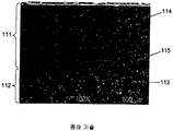
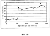
연마용 콤팩트는 내마모성, 내부식성, 내열응력성, 내충격성 및 강도를 크게요구하는 용도에 유용하다. 연마용 콤팩트를 지지 기재에 부착하는 것, 소결 처리의 제한, 또는 내부식성을 위한 소결 첨가물의 필요성과 같이 역으로 변하는 특성을 균형을 맞추는 것의 어려움이 있기 때문에, 이러한 연마용 콤팩트에 대한 설계의 절충안을 고려하게 된다. 종래 기술의 연마용 콤팩트는 이러한 설계 절충안을 극복하기 위해 층상 (layered) 미세구조를 사용한다. 종래 기술에서의, 상이한 초경질 입자 크기를 갖는 층간 천이는 도 1 에 나타나 있고, 여기서 미세한 입자 (114) 가 있는 일정한 미세한 입자 영역 (111) 및 조대한 입자 (113) 가 있는 일정하게 조대한 영역 (112) 을 각각 볼 수 있다. 도 2 는 도 1 의 콤팩트의 입자 크기의 급격한 변화를 나타내고 있고, 이 급격한 변화는 커터의 작용 커팅면으로부터 550 미크론에서 나타난다.The polishing compact is useful for applications requiring a great demand for abrasion resistance, corrosion resistance, heat resistance, impact resistance and strength. Because of the difficulty of balancing the reversed characteristics, such as the attachment of the polishing compact to the support substrate, the sintering process restriction, or the need for sintering additive for corrosion resistance, the compromise of design for such a polishing compact . Prior art polishing compacts use layered microstructures to overcome this design compromise. The interlayer transitions with different super-hard particle sizes in the prior art are shown in Figure 1 in which a uniformly
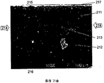
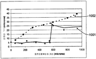
종래 기술의 콤팩트는 또한 급격한 화학적 천이가 존재한다. 도 3 의 전자 광학현미경 사진은 종래 기술의 지지된 연마용 콤팩트에서의 촉매 농도 변화 (213, 214) 를 나타내고 있다. 촉매 금속 고갈 영역 (211) 은 작용 커팅면 (217) 의 근처에 있다. 촉매 금속은 금속이 풍부한 영역 (212) 에서 밝은 회색 라인의 미세한 네트워크로 보인다. 또한, 천이는 일면 (215) 에서 다른 면 (216) 으로 향하는 라인을 따라 수행되는 전자 빔 마이크로프로브 분석에 의해 나타날 수 있다. 도 4 는 표면 (215 및 216) 사이의 라인을 따른 도 3 의 커터의 촉매 농도의 5 배 감소를 그래프로 나타내고 있다. 두 천이 모두는 대략 하나의 조대한 결정립 직경에서 발생한다.Prior art compacts also have abrupt chemical transitions. The electro-optical micrograph of FIG. 3 shows the
종래 기술의 연마용 콤팩트의 물리적 특성이나 구조의 급격한 천이는 예를 들어 미국 특허 No. 5,135,061, No. 6,187,068 및 No. 4,604,106 에 지지되고 있고, 이 개시 내용은 본 명세서에서 전체적으로 참조한다. The abrupt transition of the physical properties and structure of prior art polishing compacts is described, for example, in U.S. Pat. No. 5,135,061; 6,187,068 and No. No. 4,604,106, the disclosure of which is incorporated herein by reference in its entirety.
전술한 연마용 콤팩트 전부는, 영역 간에 급격한 천이가 있고 본질적으로 일정한 물리적 특징을 갖는, 개별적인 층을 포함한다. 물리적, 화학적 또는 구조적 특징의 급격한 천이는 연마용 콤팩트의 성능를 줄일 수 있다.All of the aforementioned abrasive compacts include individual layers having abrupt transitions between regions and having essentially constant physical characteristics. The abrupt transition of the physical, chemical or structural characteristics can reduce the performance of the polishing compact.
일 실시형태에서, 연마용 콤팩트는 고체 덩어리로 통합되는 다수의 초연마용 입자를 포함한다. 이 입자는 연속적이고, 단조적이며 또한 단축적인 특징 구배를 갖는다.In one embodiment, the polishing compact comprises a plurality of superabrasive particles incorporated into a solid body. These particles are continuous, monotonous and have a short characteristic gradient.
선택적으로, 특징 구배는 입자 크기 구배이다. 추가적으로, 축선 방향으로 입자 크기의 최대 변화율은 1 미크론 이동 당 직경이 1 미크론 미만일 수 있다.Optionally, the characteristic gradient is a particle size gradient. Additionally, the maximum rate of change of the particle size in the axial direction may be less than 1 micron per micron of travel.
대안적으로, 특징 구배는 기공 (pore) 크기 구배가 될 수 있다. 추가적으로, 축선 방향으로 기공 크기의 최대 변화율은 1 미크론 이동 당 직경이 1 미크론 미만일 수 있다.Alternatively, the characteristic gradient can be a pore size gradient. Additionally, the maximum rate of change in pore size in the axial direction may be less than one micron per micron of travel.
다른 선택으로, 특징 구배는 입자 형태 구배가 될 수 있다. 추가적으로, 축선 방향으로 입자 가로세로비의 최대 변화율은 1 미크론 이동 당 0.1 미만일 수 있다.Alternatively, the feature gradient can be a particle shape gradient. Additionally, the maximum rate of change of the aspect ratio of the particles in the axial direction may be less than 0.1 per micron movement.
또다른 선택으로, 특징 구배는 초연마용 입자 농도가 될 수 있다.As another option, the characteristic gradient can be the concentration of the primary particles.
다른 실시형태에서, 연마용 콤팩트는 고체 덩어리로 통합되는 초연마 재료를 포함한다. 이 덩어리는 각각 연속인 2 이상의 특징 구배를 갖는다. 이 구배는 (i) 단조적인 단축 구배 또는 (ii) 진동 구배일 수 있다.In another embodiment, the polishing compact comprises an ultra abrasive material incorporated into a solid body. This mass has a characteristic gradient of 2 or more in succession. This gradient may be (i) a monotonic short axis gradient or (ii) a vibration gradient.
일 실시형태에서, 연마용 콤팩트 제조 방법은, 다양한 입자 크기를 갖는, 준비된 인조 다이아몬드와 같은 일군의 초경질 입자로 시작한다. 이 입자들은 조합되고 알콜 또는 다른 유체와 혼합되어 혼합 슬러리를 형성한다. 이 슬러리는 침전되거나 그렇지 않으면 분리된다. 혼합 슬러리는 실질적으로 고체의 그레이드된 층으로 침전되고, 선택적으로는 이 층에서 다수의 조대한 입자가 먼저 침전되고 다수의 가장 미세한 입자는 맨 나중에 침전된다. 전부는 아니지만, 대부분의 남은 액체는 건조, 원심분리 또는 다른 방법으로 제거된다. 그레이드된 층의 일부는 제거되고, 전형적으로는 HPHT 조건 하에서 소결에 의해 처리되어 연마용 콤팩트를 형성하게 된다. 그레이드된 층의 일부는 선택적으로 기재에 위치할 수 있다. 초경질 입자 층은, 더 조대한 다이아몬드 입자를 갖는 표면이 기재 근처에 위치되도록 배향되어 초기 결합체를 형성하고, 이 초기 결합체는 전형적으로 HPHT 조건 하에서 소결 처리되어, 처리된 결합체를 형성하게 된다. 이 처리된 결합체로부터, 코발트 시멘티드 텅스텐 카바이드 기재에 지지된 소결 다이아몬드 연마용 콤팩트가 제조되고 회수된다. 결과적으로 얻어진 지지된 소결 콤팩트는 마무리되어 연마용 공구로 될 수 있다.In one embodiment, a compact manufacturing method for polishing begins with a group of super hard particles, such as prepared artificial diamonds, having various particle sizes. These particles are combined and mixed with an alcohol or other fluid to form a mixed slurry. This slurry is precipitated or otherwise separated. The mixed slurry is precipitated as a substantially solid, graded layer, optionally in this layer a plurality of coarse particles are first precipitated and a plurality of the finest particles are precipitated at the end. Most, but not all, of the remaining liquid is removed by drying, centrifugation or other means. A portion of the graded layer is removed and typically treated by sintering under HPHT conditions to form a polishing compact. A portion of the graded layer may optionally be located on the substrate. The super hard particle layer is oriented such that the surface with the coarser diamond particles is located near the substrate to form an initial bond which is typically sintered under HPHT conditions to form the treated bond. From this treated assembly, a compact for sintered diamond polishing supported on a cobalt-cemented tungsten carbide substrate is produced and recovered. The resulting supported sinter compact may be finished and turned into a polishing tool.
[색인어][Index]
드릴링 커터, 연마용 콤팩트Drilling cutter, compact for polishing
선택적으로, 혼합 슬러리는 비평면 고정구에서 분리되도록 된다. 추가적으로, 기재는 그레이드된 층과 맞는 계면을 가질 수 있고, 더 미세한 입자를 갖는 콤팩트의 부분에 대하여 위치할 수 있다.Optionally, the mixed slurry is allowed to separate from the non-planar anchors. Additionally, the substrate can have an interface that fits the graded layer and can be positioned relative to a compact portion with finer particles.
도 1 은 급격한 천이와 입자 크기를 나타내는, 종래 기술의 PCD 콤팩트 구조의 전자 광학현미경 사진이다.
도 2 는 도 1 의 커터와 관계된, 커팅면으로부터의 거리에 따른 입자 크기 변화를 나타내는 그래프이다.
도 3 은 종래 기술의 열적으로 안정한 지지된 연마용 복합재에서 급격한 촉매 농도 변화를 나타내는 전자 광학현미경 사진이다.
도 4 는 도 3 의 커터와 관계된, 커터 경계면으로부터의 거리에 따른 코발트 촉매 농도를 나타낸 그래프이다.
도 3 은 초연마용 커터의 다양한 층을 나타내는, 종래 기술에서의 블록도이다.
도 4 는 원주 구역에 위치한 다른 크기의 입자를 갖는 종래 기술의 커터를 나타내는 도면이다.
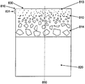
도 5 는 예시적인, 원통으로 지지되는 연마용 복합재의 단면을 나타내는 도면이다.
도 6 은 도 5 와 같은 실시형태의 예시적인 미세구조를 나타내는 전자 광학현미경 사진이다.
도 7 은 도 3 및 도 5 의 실시형태에서, 커팅면으로부터의 거리에 따른 결정립 크기를 비교한 그래프이다.
도 8 은 고배율 삽입도를 포함하는, 여러 독립 구배를 갖는 예시적인 커터의 전자 광학현미경 사진을 포함한다.
도 9 는 도 8 의 실시형태를 기초로 하는, 작용 커팅면으로부터의 거리에 따른 결정립 크기를 나타내는 그래프이다.
도 10 은 예시적인 커터에서 텅스텐 함량, 촉매 금속 농도, 및 입자 크기 구배를 나타내는 그래프이다.
도 11 은 여러 축선상에 존재하는 다모드 구배를 갖는, 지지된 연마용 콤팩트의 개략적인 단면이다.
도 12 는 도 11 의 커터 영역에서의 구배를 나타내는 광학현미경 사진이다.
도 13 은 도 12 의 예시적인 커터의 일방향에서의 입자 크기 구배를 나타내는 그래프이다.
도 14 는 도 12 의 예시적인 커터의 일방향에서의, 촉매 금속 농도를 나타낸다.
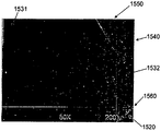
도 15 및 도 16 은 도 13 및 도 14 에 나타난 방향과는 다른 방향으로의, 도 12 의 예시적인 커터의 촉매 금속 농도 및 입자 크기 구배를 나타내는 도면이다.
도 17 은 예 3 의 예시적인 커터의 입자 크기 분포를 나타내는 그래프이다.
도 18 은 예 4 에서 사용된 다이아몬드 분말의 입자 크기 분포를 나타내는 그래프이다.
도 19 는 예 5 에서 사용된 텅스텐 분말의 입자 크기 분포를 나타내는 그래프이다.
도 20 은 콤팩트와 예시적인 침전 고정구를 나타낸다.Figure 1 is an electron optical micrograph of a prior art PCD compact structure showing abrupt transition and particle size.
Fig. 2 is a graph showing changes in particle size along the distance from the cutting face, in relation to the cutter of Fig.
3 is an electron optical micrograph showing abrupt change in catalyst concentration in the prior art thermally stable supported abrasive composites.
4 is a graph showing the cobalt catalyst concentration with distance from the cutter interface, in relation to the cutter of Fig.
Figure 3 is a block diagram in the prior art showing various layers of a prefabricated cutter.
Figure 4 is a view of a prior art cutter having different sized particles located in the circumferential zone.
Fig. 5 is a view showing a cross section of an exemplary, cylindrical supported abrasive composite material. Fig.
FIG. 6 is an electron optical micrograph showing an exemplary microstructure of the embodiment as in FIG.
FIG. 7 is a graph comparing grain sizes according to the distance from the cutting face in the embodiment of FIGS. 3 and 5; FIG.
Figure 8 includes an electron optical micrograph of an exemplary cutter with several independent gradients, including high magnification insertions.
9 is a graph showing the grain size according to the distance from the action cutting surface, based on the embodiment of Fig.
10 is a graph showing the tungsten content, catalyst metal concentration, and grain size gradient in an exemplary cutter.
Figure 11 is a schematic cross-section of a supported abrasive compact with a multimodal gradient present on several axis lines.
12 is an optical microscope photograph showing a gradient in the cutter area of FIG.
13 is a graph showing the grain size gradient in one direction of the exemplary cutter of Fig.
Figure 14 shows the catalyst metal concentration in one direction of the exemplary cutter of Figure 12;
Figs. 15 and 16 are views showing the catalyst metal concentration and particle size gradient of the exemplary cutter of Fig. 12 in a direction different from the directions shown in Figs. 13 and 14. Fig.
17 is a graph showing the particle size distribution of the exemplary cutter of Example 3. Fig.
18 is a graph showing the particle size distribution of the diamond powder used in Example 4. Fig.
19 is a graph showing the particle size distribution of the tungsten powder used in Example 5. Fig.
Figure 20 shows a compact and an exemplary settling fixture.
본 방법, 시스템 및 재료에 대해 설명하기 전에, 본 명세서는 설명한 특정 방법론, 시스템 및 재료에 한정되지 않고, 매우 다양할 수 있다. 또한, 본 명세서에서 사용된 용어는 특정한 버전이나 실시형태만을 설명하기 위한 것으로, 발명의 범위를 한정하기 위한 것은 아니다. 예를 들어, 여기 사용된 것처럼, 단수 형태는 문맥상 명확하게 다르게 나타내지 않는 한 복수 형태도 포함한다. 더불어, 여기서 "~을 포함한다" 라는 단어는 "~을 포함하나 이에 한정되지 않는다" 는 것을 의미한다. 다르게 규정되어 있지 않다면, 사용된 모든 기술적, 과학적 용어는 당업자들이 통상 이해하고 있는 것과 같은 의미를 갖는다.Before describing the present methods, systems, and materials, the present disclosure is not limited to the particular methodology, systems, and materials described, and may be highly varied. Furthermore, terms used herein are for the purpose of describing specific versions or embodiments only and are not intended to limit the scope of the invention. For example, as used herein, the singular forms include plural forms unless the context clearly dictates otherwise. In addition, the word " comprising "herein means" including, but not limited to ". Unless otherwise specified, all technical and scientific terms used have the same meaning as commonly understood by one of ordinary skill in the art.
본 명세서는, 구조나 다른 물리적 특징과 같은 하나 이상의 특징이 재료의 위치에 따라 다른 고체 재료에 관한 것이다. 이하의 용어는 다음과 같이 정의된다.The present specification relates to solid materials in which one or more features, such as structures or other physical features, depend on the location of the material. The following terms are defined as follows.
면적 평균 - 구배축선에 대한 콤팩트의 일단면에서 산정된 측정된 특징의 평균. 구배 축선에 수직인 치수는 특징을 잘 예측하기에 충분히 크고, 적어도 30 개의 조대한 입자 직경이고, 어떠한 경우는 100 이상이다. 구배에 평행한 치수는 불연속의 존재를 불분명하게 하지 않기에 충분히 작고, 관심 단면에서 가장 조대한 입자의 직경의 적어도 1 ~ 3 배이다.Area Average - The average of the measured features estimated from one side of the compact for the gradient axis. The dimensions perpendicular to the gradient axis are large enough to predict the feature well, at least 30 coarse particle diameters, and in some cases greater than 100. The dimension parallel to the gradient is small enough not to obscure the presence of discontinuity and at least 1 to 3 times the diameter of the coarsest particle in the cross section of interest.
조대한 결정립 - 콤팩트의 샘플 영역에 존재하는 결정립의 99 번째의 (제일 큰) 백분위수 직경을 갖는 다결정질 콤팩트의 결정립.Coarse grain-grains of a polycrystalline compact with a 99th (largest) percentile diameter of the grains present in the sample area of the compact.
부수적인 구배 - 대상물의 하나 또는 여러 축선을 따라 동시에 변하는 구조적 또는 물리적 특징 또는 위치에 따라 동시에 변하는 여러 구조적 또는 물리적 특징. 구배 간에 인과 관계가 존재한다.Ancillary gradients - various structural or physical features that change simultaneously depending on the structural or physical characteristics or position of the object that change simultaneously along one or several axes. There is a causal relationship between gradients.
연속 구배 - 콤팩트의 미세구조 스케일에서 급격한 변화가 없는 매끈한 구배. 수학적으로 나타내면, 연속 구배는 유한한 1 차 도함수를 가질 수 있다.Continuous Gradient - A smooth gradient with no rapid changes in the compact microstructure scale. Mathematically, the continuous gradient can have a finite first order derivative.
연속 특징 구배 - 콤팩트의 미세구조 스케일이나 그 이하에서 위치에 따라 변하는 특징. 연속 특징은 구배축선을 따른 특징의, 임의로 선택된 30 이상의 다른 라인 차단 산정 평균의 매끈한 위치 의존성을 보여준다. 다르게는, 연속 특징 구배는 더 작은 치수의 산정 영역이 구배축선에 평행하게 향하고 있는 때 특징의 면적 평균의 매끈한 위치 의존성을 보여준다.Continuous feature gradient - a feature that changes positionally at or below a compact microstructure scale. The continuity feature shows the smooth location dependence of randomly selected 30 or more different line cut-off averages of features along the gradient axis. Alternatively, the continuous feature gradient shows a smooth position dependence of the area average of the feature when the estimation area of the smaller dimension is parallel to the gradient axis.
연속 변수 - 상대적으로 작은 변화부분에서 큰 변동이 발생하지 않도록 작은 증분으로 변화가 발생하는 변수.Continuous variable - A variable that changes in small increments to avoid large fluctuations in relatively small changes.
구배 - 고체 내의 위치를 기초로 한 구조적 또는 물리적 특성의 변화. 이 정의는 구조적 및/또는 물리적 특징의 변화를 포함한다. 여기서 종종 구배는 "특징 구배" 를 일컫기도 하는데, 이 특징은 변화하는 구조적 또는 물리적 특성이다.Gradient - a change in structural or physical properties based on location within a solid. This definition includes changes in structural and / or physical characteristics. Here, the gradient is sometimes referred to as a "characteristic gradient", which is a changing structural or physical characteristic.
선형 구배 - 입자 크기, 화학적 조성 또는 양자 모두가 위치의 선형 함수에 따라 변화하는 구배.Linear gradient - a gradient in which the particle size, chemical composition, or both, change with a linear function of position.
단조 구배 - 위치에 따라 특징이 계속 증가하거나 감소하나, 진동하지는 않는 구배.Monotonic gradient - a gradient that does not oscillate, but continues to increase or decrease, depending on position.
다축 구배 - 하나보다 많은 축선을 따라 변하는 구배.Multi-Axial Gradient - A gradient that varies along more than one axis.
다모드 구배 - 하나보다 많은 독립된 구조적 또는 물리적 특징 구배. 이 구배는 서로 인과 관계를 가질 수도 있고 아닐 수도 있다. 비제한적인 예로서, 초경질 입자 크기와 조성 모두가 동시에 변하는 콤팩트는 다모드 구배를 갖는다.Multimode Gradient - More than one independent structural or physical feature gradient. These grades may or may not have a causal relationship with each other. As a non-limiting example, a compact in which both superhard particle size and composition change at the same time has a multimodal gradient.
진동 구배 - 한계값 사이에서 위치에 따라 특징이 반복적으로 변하는 연속 구배.Vibration gradient - A continuous gradient in which the features are repeatedly changed according to position between limits.
초경질 재료 - 다이아몬드, 입방 질화붕소 또는 약 3000 kg/mm2 보다 큰, 선택적으로 약 3200 kg/mm2 보다 큰 비커스 (Vickers) 경도를 갖는 다른 재료. 종종 초경질 재료는 초연마용 재료라고 한다.Super hard material-diamond, cubic boron nitride or other material having a Vickers hardness greater than about 3000 kg / mm 2 , alternatively greater than about 3200 kg / mm 2 . Often, super hard materials are called super soft materials.
단축 구배 - 하나의 방향의 축선을 따른 구배.Short axis gradient - a gradient along the axis of one direction.
단모드 구배 - 하나의 구조적 또는 물리적 특징의 구배. 비제한적인 예로서, 연마용 콤팩트에서 일 방향을 따라 증가하는 초경질 입자 직경은 단모드 구배가 된다. 대상물의 여러 축선을 따른 부수적인 구배는 단모드 구배와 연관될 수 있다.Short mode gradient - the gradient of one structural or physical feature. By way of non-limiting example, the super hard particle diameter increasing along one direction in the abrasive compact results in a short mode gradient. Ancillary gradients along various axes of the object can be associated with a short mode gradient.
여기서 개시된 실시형태에 따르면, 연마용 콤팩트는 고체 덩어리로 통합되는 다이아몬드, 입방 질화붕소 (CBN) 또는 다른 초경질 재료 입자를 포함한다. 이하에 알려진 모든 통합 방법은, 고압/고온 (HPHT) 조건으로 알려진, 상승된 온도와 압력에서 소결시키는 것과 같이, 덩어리를 만들어내도록 이용될 수 있다. 다결정질 다이아몬드 (PCD) 또는 다결정질 CBN (PCBN) 의 경우, 이러한 조건은 전형적으로 4 기가파스칼 (Gpa) 을 넘고 온도는 1200℃ 를 넘는다. 연마용 콤팩트는 자유롭게 서 있을 수 있고, 기재에 부착되어 지지된 연마용 콤팩트를 형성할 수 있고/있거나, 처리되어 열적으로 안정된 또는 여과된 연마용 콤팩트를 형성할 수 있다.According to the embodiments disclosed herein, the polishing compact comprises diamond, cubic boron nitride (CBN) or other ultra hard material particles incorporated into a solid body. All of the consolidation methods known below can be used to produce lumps, such as sintering at elevated temperatures and pressures, known as high pressure / high temperature (HPHT) conditions. For polycrystalline diamond (PCD) or polycrystalline CBN (PCBN), these conditions typically exceed 4 gigapascals (Gpa) and temperatures exceed 1200 ° C. The polishing compact can stand freely and can be attached to a substrate to form a supported abrasive compact and / or can be processed to form a thermally stable or filtered abrasive compact.
일 형태에서, 연마용 콤팩트는 연속적으로 분포된 구조적 또는 물리적 특징의 연속 단축 특징 구배를 하나 이상 가질 수 있다. 도 5 는 굴착 비트 (earth-boring bit) 에서 드릴링 커터로 사용될 수 있는 형태와 같은 원통형의 지지된 연마용 복합재의 개략적인 단면도이다. 도시된 단면은 드릴링 커터의 원통 축선 (850) 과 평행하다. 이러한 커터는, 시멘티드 텅스텐 카바이드와 같은 지지 재료로 만들어진 기재 (820) 를 포함하고, 소결된 초경질 입자의 콤팩트 (810) 가 동축으로 상기 기재의 하나 이상의 단부에 부착되어 있다. 연마용 콤팩트의 자유 평면 단부 (830) 와 원통형 연마용 콤팩트 측면 (831) 의 일부분은 작용 커팅면이다.In one form, the polishing compact may have one or more continuous shortening characteristic gradients of continuously distributed structural or physical features. Figure 5 is a schematic cross-sectional view of a cylindrical supported abrasive composite, such as the form that can be used as a drilling cutter at an earth-boring bit. The cross section shown is parallel to the
개시된 실시형태에서, 연마용 콤팩트 미세구조는 전형적으로는 입자 형태인 초경질 재료의 연속적인 크기 구배를 갖는다. 도 5 에 도시된 구배는 커터 원통 축선 (850) 과 실질적으로 평행하다. 그러나 상부면 (830) 과 측면 (831) 으로부터 원하는 각도로 오프셋된 라인을 따라 콤팩트의 코너 (816) 로부터 내측으로 향하는 구배와 같은, 다른 위치 구배도 가능하다. 도시된 초경질 입자 크기의 단모드 단축 구배는 독립적인 연속 특징 구배이다. 미세한 초경질 입자 (813) 의 상대적으로 높은 농도는 커팅면 근방에서 높은 내연삭 마멸성 및 내파괴성을 제공하고, 더 조대한 입자 (814) 의 상대적으로 높은 농도가 텅스텐 카바이드 기재 (820) 근방에 존재하게 된다. 미세한 입자 (811) 영역은 기재 (820) 를 향하여 어느 정도의 축선 방향 거리만큼 형성되어, 작용 커팅면 (830 및 831) 전체를 둘러싸게 된다. 전술한 바와 같이 측정된 선 또는 면적 평균 입자 크기는 기재 (820) 쪽으로 축선 방향으로 매끈하고 연속적으로 증가한다.In the disclosed embodiment, the abrasive compact microstructure typically has a continuous size gradient of ultra hard material in particulate form. The gradient shown in FIG. 5 is substantially parallel to the cutter
도 6 의 광학현미경 사진은 도 5 에 개략적으로 도시된 것과 같은 실시형태의 일 미세구조를 나타낸다. 초경질 입자 크기 (910) 는 광학현미경 사진에서 측정하고 기록된다. 작용 커팅면 (930 및 931) 은, 이 실시예에서 높은 내마모성 (abrasion resistance) 을 위해 크기가 약 6 ~ 8 미크론인 초경질 입자를 포함한다. 다른 크기의 입자도 사용될 수 있다. 초경질 입자 크기는 기재 경계면 (940) 을 향하는 방향으로 약 40 미크론까지 연속적으로 증가한다. 초경질 입자 크기 특징은 연속 구배로 변화하고, 따라서 종래 기술의 층상화된 불연속적인 혼합 구배와는 확연히 다르다. 어떤 실시형태에서, 입자 크기 구배의 최대 변화율은 구배 축선을 따라서 1 미크론 이동 (즉, 물리적 거리) 당 입자 크기가 1 미크론 미만일 수 있다. 대안적인 구배는 기공 크기가 될 수 있으며, 비슷한 최대 변화율을 갖는다.The optical microscope photograph of Fig. 6 shows a microstructure of an embodiment as schematically shown in Fig. The super
도 7 은 (도 3 에 도시된 것과 같은) 종래 기술의 콤팩트 (1001) 와 도 5 및 도 6 의 실시형태에서의 초경질 입자 크기 변화를 그래프로 나타내어 비교한 것이다. 초경질 입자 크기는 드릴링 커터의 원통 축선 (도 5 의 축선 (850)) 과 평행한 방향으로 측정된다. 도 7 은 도 5 의 실시형태에서의 초경질 입자 크기의 연속 구배 (1002) 를, 도 3 의 종래 기술의 급격한 입자 크기 변화 (1001) 와 명확하게 대비하여 나타낸다. 도 5 의 실시형태가 입자 크기는 공칭적으로 선형 구배 (1002) 이지만, 선형 구배가 요구되는 것은 아니고, 본 발명의 범위가 선형 구배에 한정되는 것도 아니다. 이 콤팩트는 또한 몇 개의 부수적인 구배를 가질 수 있는데, (ⅰ) 부수적인 연속 단축 내마모성 구배 (연속 변수), (ⅱ) 부수적인 연속 단축 조성 구배 (불연속 변수), 및 (ⅲ) 촉매 금속 풀 (pool) 크기, 열 전도성 및/또는 열팽창과 같은 다른 것 등이 있다. 설명된 구배는 나타난 연마용 콤팩트 부피의 일부 또는 전체 부피를 포함할 수 있다. 설명된 연마용 콤팩트는 층상 구조의 불연속 계면의 응력 집중이나 오염 없이 종래기술의 목적을 달성할 수 있다. 설명된 연마용 콤팩트는 연속적으로 분포된 콤팩트 변수의 연속 단축 구배의 제 1 실시예이다.FIG. 7 graphically compares the ultra-hard particle size variation in the prior art compact 1001 (as shown in FIG. 3) and the embodiment of FIGS. 5 and 6. The ultra-hard particle size is measured in a direction parallel to the cylindrical axis of the drilling cutter (
다른 실시형태는 다모드 구배를 갖는 연마용 콤팩트이다. 이러한 독립 구배는 연속적이거나 아닐 수 있고, 연속적 또는 불연속적으로 분포된 구조적 또는 물리적 특징을 포함할 수 있다. 이 구배는 단조적이거나 혹은 진동할 수 있다. 예를 들어, 연마용 콤팩트는 연속적으로 분포된 초경질 입자와 첨가물 입자의 크기 및 불연속적으로 분포된 조성 특징의 독립 구배를 포함할 수 있다.Another embodiment is a polishing compact having a multi-mode gradient. This independent gradient may or may not be continuous, and may include structural or physical features distributed continuously or discontinuously. This gradient can be monotonic or oscillatory. For example, the abrasive compact may include an independent gradient of the size and non-continuously distributed composition characteristics of the additive particles and the continuously distributed super hard particles.
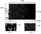
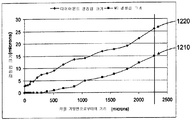
도 8 에 나타난 것을 예로 드는 이러한 실시형태에서, 드릴링 커터의 단면의 광학현미경 사진은 다수의 독립 동축 구배를 갖는 연마용 복합재를 나타내고, 텅스텐 카바이드 및/또는 다른 재료로 된 기재 (1120) 를 포함하고, 다이아몬드와 텅스텐 카바이드 및/또는 다른 재료로 된 연마용 콤팩트 (1110) 가 상기 기재에 동축선으로 부착되어 있다. 연마용 콤팩트의 자유 평면 단부 (1130) 와 원통형 연마용 콤팩트 표면의 인접부 (1135) 가 작용 커팅면이다. 고배율 삽입도 (1115) 에 나타난 바와 같이, 이 실시예에서 약 3 미크론 미만의 입자 크기를 갖는 미세한 초경질 입자 (1113) 는 작용 커팅면을 포함하고, 높은 내연삭 마멸성 및 내파괴성을 제공하고, 고배율 삽입도 (1116) 에 나타난 조대한 입자는 약 20 미크론을 넘는 입자 크기 (1114) 를 갖고 텅스텐 카바이드 기재 (1120) 근처에서 HPHT 소결을 향상시킨다. 미세한 초경질 입자 영역은 텅스텐 카바이드 기재 (1120) 를 향하여 어느 정도의 축선 방향 거리만큼 연장되고, 작용 커팅면 (1135) 의 연장부를 둘러싼다. 특징 입자 크기 구배는 약 3 미크론의 평균 입자 크기에서 시작하고, 자유 평면 단부 (1130) 에서 기재 (1120) 방향을 향하여 축선 방향으로 연속적으로 증가하여, 약 20 미크론의 최종 입자 직경에 도달한다. 도 9 는 자유 평면 단부 및/또는 작용 커팅면으로부터의 거리에 따른 다이아몬드 크기 구배 (1220) 를 나타내는 그래프를 나타낸다.8, an optical microscope photograph of a cross section of the drilling cutter shows a polishing composite having a plurality of independent coaxial gradients and includes a
본 실시형태의 제 2 구배는 전술한 초경질 입자 크기 구배와 독립적이고 동축이며, 텅스텐 카바이드 첨가물 특징의 구배를 포함한다. 텅스텐 카바이드 첨가물은 입자 크기 및 혼합물 조성 구배를 모두 갖는다. 도 8 의 삽입도 A 및 B 와 도 9 의 그래프에 나타난 바와 같이, 평균 텅스텐 카바이드 입자 크기 구배 (1210) 는 텅스텐 카바이드 기재 (1120) 근처에서의 약 15 미크론 (1114) 에서부터 작용 커팅면 (1130) 에서의 거의 0 미크론 (1113) (텅스텐 카바이드가 거의 존재하지 않는 것을 의미한다) 까지 연속적으로 감소한다. 초경질 입자 크기 구배와 동축인 연속 텅스텐 카바이드 조성 구배는 텅스텐 카바이드 기재 (1120) 근처에서의 약 50 중량 % 에서부터 평면 단부 및/또는 작용 커팅면 (1130) 에서의 대략 0 % 까지 감소한다.The second gradient of this embodiment is independent of and coaxial with the above super hard particle size gradient and comprises a gradient of the tungsten carbide additive feature. The tungsten carbide additive has both a particle size and a mixture composition gradient. 8, the average tungsten carbide
도 10 (원소 농도 미시분석) 은 임의적인 조성 유닛에서 이러한 구배의 독립성을 나타낸다. 텅스텐 원소로 측정한, 연마용 콤팩트의 텅스텐 카바이드 함량 (1310) 은 텅스텐 카바이드 기재에서 멀어지는 축선 방향으로 감소한다. 독립적인 초경질 입자 크기 구배 (1320) 또한 기재에서 멀어질수록 감소할 수 있음을 보여주고, 코발트 촉매 금속 농도 (1320) 는 동일한 방향으로 증가할 수 있다. 앞의 실시형태처럼, 코발트 입자 크기나 다이아몬트 농도과 같은 다른 부수적인 구배가 존재할 수 있다. 독립 구배는 연마용 콤팩트의 일부 부피 또는 전체 부피를 포함할 수 있다. 다모드 구배는, 종래기술에서의 오염과 응력 집중을 줄이면서 추가적으로 콤팩트 설계의 유연성을 제공할 수 있다.Figure 10 (elemental concentration microanalysis) shows the independence of this gradient in arbitrary composition units. The
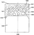
또다른 실시형태는 연마용 콤팩트 내의 다수 축선 상의 독립 연속 구배를 포함한다. 이 구배는 전술한 어떠한 유형이 되어도 좋다. 도 11 은 다수 축선상에 다모드 구배가 존재하는, 지지된 연마용 콤팩트 (1400) 의 개략적인 단면이다. 개략적인 단면은 콤팩트의 실린더 축선 (1450) 과 교차한다. 반경 방향 (1460) 또한 도시하였다. 연마용 콤팩트의 외부는 평면 작용 커팅면 (1410) 과 원주면 (1411) 을 포함하고, 이 원주면의 일부가 작용 커팅면이 될 수 있다. 본 실시형태에서 미세한 것 (1431) 에서 조대한 것 (1432) 까지 다양할 수 있는 초경질 입자가 연마용 콤팩트에 존재한다. 조성 구배, 특성 또는 다른 구배와 같은 제 2 구배 (1440) 가 연마용 콤팩트에 존재한다. 이 제 2 구배 특징은 쉐이드가 변화하는 것으로 나타내었다. 지지 기재 (1420) 와 연마용 콤팩트 (1400) 의 계면에 비평면부 (1470) 가 존재할 수 있다. 이 비제한적인 예에서, 연마용 콤팩트의 외부면에 본질적으로 하나의 크기의 입자가 존재한다. 입자는 정확하게 크기가 같을 필요는 없으나, 10 % 이하의 변동, 5 % 이하의 변동 또는 1 % 이하의 변동과 같이 크기가 거의 비슷할 필요만 있으면 된다. 내부에 다른 크기의 입자가 존재할 수 있다. 입자는 1 이상의 축선에서 평균 또는 중간 크기가 변할 수 있고, 입자 크기 변화율은 축선 방향 (1450), 반경 방향 (1460) 또는 다른 방향과 같이, 다른 축선에 따라 다양할 수 있다. 다른 특징 구배는 촉매 금속 농도; 촉매 금속 분포; 기공 분율로 알려진, 다공성 콤팩트의 양 또는 분율인 초경질 입자 농도; 기공 크기로 알려진, 콤팩트에 존재하는 기공의 크기; 및 형상 분포의 부수적인 구배 및 다른 물리적 특징에서 파생되는 구배를 포함할 수 있다. 제 2 구배 (1440) 는 전술한 어떠한 형태의 구배일 수 있고, 예를 들어 추가적인 상의 농도 또는 입자 크기의 구배이다. 다중 구배는 진동, 단조적이거나 선형 또는 다른 형태일 수 있다.Yet another embodiment includes an independent continuous gradient over multiple axes in a polishing compact. This gradient may be any of the types described above. 11 is a schematic cross-section of a supported abrasive compact 1400 in which there is a multimodal gradient on multiple axis lines. The schematic cross-section intersects the
도 12 는 도 11 의 영역 (1470) 에서의 실제 다축, 다모드 구배의 광학현미경 사진이다. 커터 원통 축선 (1550) 과 평행한 방향 및 반경 방향 (1560) 이 나타나 있다. 지지 기재 (1520), 조대한 초경질 연마용 결정립 (1532) 및 미세한 초경질 연마용 결정립 (1531) 이 나타나 있다. 반경방향 및 축선방향 초경질 입자 크기 구배가 존재한다. 또한, 입자 크기의 변화율은 선택된 축선에 따라 다양하다.12 is an optical microscope photograph of an actual multi-axis, multi-mode gradient in the
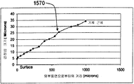
도 13 은 콤팩트의 외부 근처에서의 약 5 미크론에서부터 카바이드 기재 (1520) 근처에서의 약 35 미크론까지 초경질 입자 크기의 매끄러운 축선방향 구배 (1570) 를 보여준다. 도 14 는 단일 선스캔으로 평가했을 때 동일 방향으로의 촉매 금속 농도 구배 (1580) 를 나타낸다. 연마용 입자에 존재하는 훨씬 더 낮은 레벨의 촉매로 인한 촉매 농도의 변화성은 구배의 존재를 불확실하게 하지 않는다. 전술한 바와 같이 구배와 평행한 선스캔의 통계학적으로 의미있는 수 또는 또는 면적 평가를 평균하여 변화성은 줄어들 수 있다. 도 15 및 도 16 은 반경 방향으로의 동일한 물리적 특징 구배를 나타낸다. 더 낮은 변화율이 반경 방향으로 존재한다. 다축 구배가 설계의 유연성을 더 향상시킨다.FIG. 13 shows a smooth
전체 표면 또는 부피, 예를 들어 전체 외부 표면이 하나 이상의 실질적으로 일정한 물리적 특징을 갖고, 다른 영역에서는 구배를 갖는 연마용 콤팩트에서 일 형태의 다축 구배를 발견할 수 있다. 예를 들어, 이 실시형태는, 전체 외부 표면에서 일정한 초경질 입자 크기를 갖고 소결 또는 응력 관리를 향상시키기 위한 내부 구배가 있는 굴착 비트 커터를 위한 지지된 연마용 복합재를 포함할 수 있다. 이러한 실시형태에서, 부수적인 구배가 존재할 수 있다. 이 실시형태는 커터를 사용하는 동안 바람직하지 않은 우선적인 마모를 없애면서 설계의 유연성을 더 높힐 수 있다.It is possible to find one form of the multiaxial gradient in the polishing compact, where the entire surface or volume, for example the entire outer surface, has one or more substantially constant physical characteristics, and the gradient in other areas. For example, this embodiment may include a supported abrasive composite for an excavation bit cutter having an internal gradient to enhance sintering or stress management, having a constant ultrafine grain size at the entire outer surface. In such an embodiment, there may be an incidental gradient. This embodiment can further increase design flexibility while eliminating undesirable preferential wear during use of the cutter.
다른 실시형태에서, 몇몇 구조적 또는 물리적 특징은, 모든 방향은 아니나 어떠한 방향으로는 변할 수 있다. 예를 들어, 연속 축선 방향 조성 구배가 반경 방향 초경질 입자 크기 구배와 함께 존재할 수 있다. 이러한 실시형태에서, 부수적인 구배가 존재할 수 있다.In other embodiments, some structural or physical features may vary in any direction, but not in all directions. For example, a continuous axial composition gradient may be present along with a radial ultra hard particle size gradient. In such an embodiment, there may be an incidental gradient.
또다른 형태에서, 개시된 콤팩트는 초경질 입자와 혼합된 다른 상의 불연속 구배를 보여줄 수 있다. 일 실시예에서, 반응성 금속 가공용 커팅 공구는 작업물에 대해 비반응성인 작용 커팅면을 가지며 동시에 기재에 대해서는 고반응성인 지지된 연마용 콤팩트를 필요로 한다. 연마용 복합재에 산화 알루미늄을 첨가하면 커팅면 반응성을 유리하게 줄일 수 있으나, 불리하게도 연마용 복합재와 텅스텐 카바이드 기재의 계면 결합 강도가 감소된다. 다양한 실시형태의 연마용 콤팩트는 기재 경계면에서 더 낮은 산화 알루미늄 농도 조성까지 연속적으로 변하는, 산화 알루미늄이 풍부한 작용 커팅면을 가질 수 있다. 이렇게 해서, 커팅 공구는 수명이 더 향상되고, 바람직하지 않은 급격한 변화가 거의 없거나 전혀 없으며, 텅스텐 카바이드 기재에 더 강하게 부착되게 된다.In yet another form, the disclosed compact may exhibit a discontinuous gradient of another phase mixed with super hard particles. In one embodiment, the cutting tool for reactive metal processing requires a supported abrasive compact having an action cutting surface that is non-reactive to the workpiece, while at the same time being highly reactive with the substrate. Adding aluminum oxide to the abrasive composite material can advantageously reduce the cut surface reactivity, but disadvantageously reduces the interfacial bond strength between the abrasive composite and the tungsten carbide substrate. The polishing compacts of the various embodiments may have aluminum oxide-rich working cutting surfaces that continuously change from the substrate interface to the lower aluminum oxide concentration composition. In this way, the cutting tool has a longer lifetime, little or no undesirable abrupt change, and is more strongly attached to the tungsten carbide substrate.
다른 실시형태는 입자 형태 구배를 갖는다. 연마용 콤팩트의 입자는 다양한 형태를 가질 수 있다. 가로세로비 (aspect ratio), 입자의 주축선과 부축선 간의 수치비 또는 입자의 직경은 입자 형태를 정량화하는데 이용될 수 있다. 입자 형태 구배가 있는 연마용 콤팩트는, 일부 부피나 영역에서 구형 또는 덩어리 형태의 입자로 이루어지며 다른 부피나 영역에서는 더 편원 (oblate), 평면, 위스커형 (whiskery) 의 입자를 갖는다. 연마용 콤팩트는 낮은 가로세로비의 입자를 가지며 연속 구배를 통해 작은판 (platelet) 또는 위스커 (whisker) 와 같이 높은 가로세로비 입자를 갖는 영역이 되는 영역을 가질 수 있다. 가로세로비가 더 큰 영역은 다른 파괴, 강도 또는 트라이볼로지 (tribological), 화학 또는 전기적 특징을 제공한다. 어떤 실시형태에서, 가로세로비의 최대 변화율은 축선을 따라 1 미크론 이동 (즉, 거리) 당 0.1 을 넘지 않는다.Other embodiments have a particle shape gradient. The compact particles for polishing may have various shapes. The aspect ratio, the numerical ratio between the major axis and minor axis of the particle, or the diameter of the particle can be used to quantify the particle shape. A polishing compact with a particle shape gradient consists of particles in the form of spheres or lumps in some volume or area, and more oblate, planar, whiskery particles in other volumes or areas. The abrasive compact may have areas of low aspect ratio and areas that become areas with high aspect ratio particles such as platelets or whiskers through continuous gradients. Areas with larger aspect ratios provide different fracture, strength or tribological, chemical or electrical characteristics. In certain embodiments, the maximum rate of change in aspect ratio does not exceed 0.1 per micron shift (i.e., distance) along the axis.
다른 실시형태에서, 전기 전도성 및 내마모성 구배는 제조된 목재 제품을 가공하기 위한 초경질 입자 연마용 콤팩트를 제공한다. 이러한 용도로, 높은 레벨의 벌크 전기 전도성을 갖는 다이아몬드계 연마용 콤팩트가 다이아몬드 커터의 전자 불꽃 가공에 적합하다. 또한, 이 용도에서, 조대한 다이아몬드 입자를 최대 함량으로 갖는 구조에서 높은 내마모성이 얻어진다. 이러한 조대한 다이아몬드 입자가, 단체형의 균질한 연마용 콤팩트에 포함되는 경우, 전자 불꽃 가공이 더욱 어려워진다. 이 실시형태는, 더 미세한 초경질 입자로의 구배가 있고 부수적인 더 높은 전기 전도성을 갖는 작용 커팅면에서의 조대한 초경질 입자를 통해 이러한 문제점을 해결할 수 있다. 입자 크기의 일정한 연속 구배는 높은 내마모성 연마면과 함께 높은 벌크 전기 전도성을 제공할 수 있다.In another embodiment, the electrical conductivity and abrasion resistance grades provide compacts for polishing ultra hard particles for processing manufactured wood products. For this purpose, a diamond-based polishing compact having a high level of bulk electrical conductivity is suitable for the electronic flame machining of a diamond cutter. Further, in this application, a high abrasion resistance is obtained in the structure having the largest amount of coarse diamond particles. When such a coarse diamond particle is contained in a uniform compact polishing compact, the electron flame processing becomes more difficult. This embodiment can overcome this problem through coarse super hard particles in the working cutting surface having a gradient to finer super hard particles and having an additional higher electrical conductivity. A constant continuous gradient of particle size can provide a high bulk electrical conductivity with a high abrasion resistant polishing surface.
다른 실시형태는 발명된 연속 구배를 다른 형태에 적용한다. 환형 연마용 콤팩트 형상은 와이어 드로잉 다이 (wire drawing die) 에 적합하다. 이 연마용 콤팩트에서 구조적 또는 물리적 특징은 변화하여, 원하는 특성을 갖는 환형 표면을 생성한다. 환형 형태에서, 어떠한 구배는 테이퍼진 원통형 또는 환상 마모면에 대략 수직 (반경방향) 이 될 것이다.Other embodiments apply the inventive continuous gradients to other forms. The compact shape for annular polishing is suitable for wire drawing die. In this polishing compact, the structural or physical characteristics change to produce an annular surface with the desired properties. In the annular form, any gradient will be approximately perpendicular (radial) to the tapered cylindrical or annular wear surface.
조성 및 초경질 입자 크기 구배에 대해 설명하였고, 다른 구배도 효용성을 가질 것이다. 잠재적으로 이용되는 단모드, 다모드, 단축 및 다축 구배는 다음과 같다 : 상 조성, 입자 형태, 전기 전도성, 열 전도성 또는 팽창, 음향 및 탄성 특성, 초경질 입자 재료 외의 다른 재료의 포함, 밀도, 기공 크기 및 형태, 강도, 파괴 인성, 광학적 특성.Composition and super hard particle size gradients, and other gradients will have utility. The potentially used short mode, multimode, short axis and multiaxial gradients are as follows: phase composition, particle shape, electrical conductivity, thermal conductivity or expansion, acoustical and elastic properties, inclusion of other materials, Pore size and shape, strength, fracture toughness, optical properties.
일 실시형태에서, 연마용 콤팩트를 만드는 방법은 일정 범위의 입자 크기를 가진 준비된 일군의 초경질 입자 (인조 다이아몬드와 같은) 로부터 시작한다. 입자는 알코올 또는 다른 유체와 결합되고 혼합되어 혼합 슬러리를 형성한다. 혼합 슬러리는 중력, 원심력, 전기장, 자기장 또는 다른 방법에 의해 영향을 받아서 분리된다. 혼합 슬러리는 실질적으로 고체인 그레이드된 층으로 침전되서, 선택적으로 이 층에서는 다수의 조대한 입자들이 먼저 침전되고 다수의 가장 미세한 입자들이 마지막에 침전된다. 전부는 아니나, 몇몇 남은 액체는 건조, 원심분리 또는 다른 방법으로 제거된다. 그레이드된 층의 일부는 제거되어 선택적으로 기재에 위치한다. 초경질 입자 층은, 더 조대한 다이아몬드 입자를 갖는 표면이 기재 근처에 위치하도록 배향되어 초기 결합체를 형성할 수 있고, 이 초기 결합체는, 전형적으로는 HPHT 조건 하에서 소결 처리되어 처리된 결합체를 형성한다. 이 처리된 결합체로부터, 코발트 시멘티드 텅스텐 기재에 지지된 소결된 다이아몬드 연마용 콤팩트가 생산되고 회수된다. 결과적으로 얻어진 지지된 소결 콤팩트는 마무리되어 연마용 공구로 될 수 있다.In one embodiment, a method of making a polishing compact begins with a set of prepared super hard particles (such as artificial diamonds) having a range of particle sizes. The particles are combined with an alcohol or other fluid and mixed to form a mixed slurry. The mixed slurry is separated by gravity, centrifugal force, electric field, magnetic field or other methods. The mixed slurry is precipitated with a graded layer that is substantially solid, optionally, in this layer, a number of coarse particles are first precipitated and a plurality of the finest particles are finally precipitated. Some, if not all, of the remaining liquid is removed by drying, centrifugation or other methods. A portion of the graded layer is removed and optionally placed on the substrate. The super hard particle layer can be oriented such that the surface with the coarser diamond particles is located near the substrate to form an initial bond, which is typically sintered under HPHT conditions to form a treated bond . From this treated assembly, a sintered diamond polishing compact supported on a cobalt cemented tungsten substrate is produced and recovered. The resulting supported sinter compact may be finished and turned into a polishing tool.
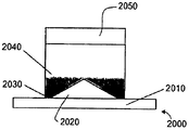
선택적으로, 혼합 슬러리는 비평면 고정구 내에서 분리되게 된다. 고정구 (2000) 의 비평면 요소의 예는 도 20 에 나타나 있다. 도 20 에 나타난 바와 같이, 고정구 (2000) 는 평면부분 (2010) 과 비평면부분 (2020) 을 포함할 수 있다. 비평면부분은 두 경사가 하나의 피크에서 만나는 것, 원뿔 형태, 반구 형태, 피라미드 형태 또는 다른 비평면 형태와 같이, 어떠한 비평면 형태가 되어도 좋다. 더 큰 농도의 조대한 입자 (2030) 는 비평면 구조 근처에 침전되고, 더 큰 농도의 미세한 입자 (2040) 는 비평면 구조에서 멀리 떨어진 더 높은 지점에 침전된다. 또한 선택적으로, 카바이드 또는 다른 기재는, 그것이 배치되는 침전된 다이아몬드 층의 크기와 형태와 맞는 계면 크기 및 형태를 가질 수 있다.Optionally, the mixed slurry is separated in a non-planar anchor. An example of the non-planar element of
실시예Example
예 1 - 종래 기술. 이하는 미국 특허 No. 3,831,428; 3,745,623 및 4,311,490 이다. Diamond Innovations, Inc 에서 제조한 MBM® 그레이드, 3 미크론 직경의 인조 다이아몬드가 16 mm 직경의 고순도 탄탈륨 호일 컵 내에 대략 1.5 mm 의 일정한 깊이로 위치하였다. 이 미세한 층 상부에 제 2 의, 1.5 mm 로 일정한 두께의 40 미크론 MBM 분말 층이 추가되었다. 16 mm 의 실린더형 13 중량 % 코발트 시멘티드 텅스텐 카바이드 기재 또한 탄탈륨 호일 컵 내에 위치하였다. 이 결합체는 약 15 ~ 45 분간 55 ~ 65 Kbar 의 압력과 약 1500 ℃ 의 온도로, 인용된 특허의 셀 구조체 및 교시에 따라 처리되었다. 회수된 지지된 연마용 콤팩트는 시멘티드 카바이드 기재에 지지된, 소결된 다이아몬드 층 구조체를 가졌다. 이 커터의 구조는 도 1 및 도 2 에 나타나 있다.Example 1 - Prior art. U.S. Pat. 3,831,428; 3,745,623 and 4,311,490. The MBM® grades, manufactured by Diamond Innovations, Inc., 3-micron diameter artificial diamonds were positioned at a constant depth of approximately 1.5 mm in a high purity tantalum foil cup of 16 mm diameter. A second, 1.5 mm thick, 40 micron MBM powder layer was added on top of this fine layer. A 16 mm cylindrical 13 wt% cobalt cemented tungsten carbide substrate was also placed in the tantalum foil cup. This combination was treated according to the cell structure and teachings of the cited patent, at a pressure of 55-65 Kbar and a temperature of about 1500 ° C for about 15 to 45 minutes. The recovered supported abrasive compact had a sintered diamond layer structure supported on a cemented carbide substrate. The structure of this cutter is shown in Figs.
예 2 - 종래 기술. 드릴링 커터는 미국 특허 No. 4,224,380 에 설명된 것과 같은 방법을 이용하여 3HCl : 1HNO3 산에서 가열될 수 있고, 여기서 카바이드 기재는 보호층에 의해 피복되어 있어서, 코발트가 고갈된 영역을 얻는다. 이러한 커터의 구조는 도 2 및 도 3 에 나타나 있다.Example 2 - Prior art. Drilling cutters are described in U.S. Pat. Using the same method as that described in the 4,224,380 3HCl: can be heated in 1HNO acid 3, where carbide substrate in is covered with a protective layer, to obtain a cobalt-depleted zone. The structure of such a cutter is shown in Figs. 2 and 3. Fig.
예 3. 도 17 에 나타나 있는 입자 크기 분포의 45 g 의 인조 다이아몬드가 준비되어 450 cc 의 99.9 % 순도의 이소프로필 알콜 (isopropyl alcohol) 과 결합될 수 있다. 이러한 재료는 TURBULA® 믹서에서 2 분간 혼합될 수 있다. 혼합 슬러리를 100 mm 직경의 플라스틱 용기에 붓고 8 시간 동안 침전되도록 할 수 있다. 남은 액체를 디캔팅 (decanting) 과 증발을 통해 조심스럽게 제거할 수 있다. 침전된 다이아몬드 층이 굳어지면, 침전된 층에서 16mm 디스크가 잘려나올 수 있다. 다이아몬드 층은 탄탈륨 (Ta) 호일 컵 안에서 배향되어 조대한 입자를 텅스텐 카바이드 기재 주위에 위치하도록 할 수 있다. 원통형 코발트 시멘티드 텅스텐 카바이드 기재는 조대한 다이아몬드 입자의 위에 위치할 수 있다. 이 결합체는 약 15 ~ 45 분간 55 ~ 65 Kbar 의 압력과 약 1500 ℃ 의 온도로 HPHT 처리를 이용하여 처리될 수 있다. 정확한 조건은 여러가지 변수에 의하지만, 이 변수들은 가이드라인으로 제시된다. 회수된 결합체는 시멘티드 텅스텐 카바이드 기재에 지지되는 소결된 다이아몬드 연마용 콤팩트를 생산할 것이고, 이는 마무리되어 연마용 공구로 될 수 있다. 이러한 구조의 샘플은 구조 평가를 위해 축선방향으로 반으로 잘려서 연마되었고, 이 예에 따른 구조는 도 6 에 나타나 있다.Example 3. 45 g of artificial diamond of particle size distribution shown in Fig. 17 is prepared and can be combined with isopropyl alcohol of 99.9% purity of 450 cc. These materials can be mixed in a TURBULA® mixer for 2 minutes. The mixed slurry can be poured into a 100 mm diameter plastic container and allowed to settle for 8 hours. The remaining liquid can be carefully removed through decanting and evaporation. When the precipitated diamond layer becomes hard, a 16 mm disc may be cut off from the deposited layer. The diamond layer may be oriented in a tantalum (Ta) foil cup so that coarse particles are positioned around the tungsten carbide substrate. Cylindrical cobalt cemented tungsten carbide substrates can be placed on top of coarse diamond particles. The conjugate can be treated using HPHT treatment at a pressure of 55-65 Kbar and a temperature of about 1500 < 0 > C for about 15-45 minutes. The exact conditions depend on a number of variables, but these are presented as guidelines. The recovered composite will produce a sintered diamond abrasive compact supported on a cemented tungsten carbide substrate, which can be finished and made into a polishing tool. A sample of this structure was cut in half in the axial direction for polishing the structure, and the structure according to this example is shown in Fig.
이 예의 단축의 연속적으로 그레이드된 구조의 효용을 설명하기 위하여, 몇 개의 커터가 준비되고 내충격성 및 내마모성에 대해 실험하여다. 이 결과를 Diamond Innovations, Inc. 의 TITAN 상업용 드릴링 커터와 비교하였다. 충격 실험은 INSTRON 9250 낙하 테스터에서 수행되었다. 내마모성 실험 (부피 효율 또는 G 비율) 은 화강암 원통을 날카롭고 모따기 (chamfer) 되지 않은 커터로 선삭하여 측정하였다. 이 예의 커터의 성능은 충격 성능에서는 100 % 이상, 마모에서는 500 % 이상 상업 연마용 커터를 능가하였다. 자세한 실험 결과는 표 1 과 같다.In order to illustrate the utility of the shortened, continuously graded construction of this example, several cutters are prepared and tested for impact resistance and abrasion resistance. The results are reported by Diamond Innovations, Inc. Of the TITAN commercial drilling cutter. The impact test was performed on an INSTRON 9250 drop tester. Abrasion resistance experiments (volume efficiency or G ratio) were measured by turning the granite cylinder with a sharp, non-chamfered cutter. The performance of the cutter in this example surpassed the commercial abrasive cutter by more than 100% for impact performance and over 500% for abrasion. Detailed experimental results are shown in Table 1.
예 4. 예 3 에 나타나 있는 바와 같이, 입자 크기 분포가 도 19 에 나타난 45 g 의 인조 다이아몬드 분말이, 입자 크기 분포가 도 19 에 나타난 12 g 의 텅스텐 분말 (99 % 순도 및 소스) 과 결합되었다. 제조 및 소결 처리는 도 3 과 같이 이루어졌다. 회수된 복합재 콤팩트는 시멘티드 카바이드 기재에 지지된, 소결된 다이아몬드 층 구조를 가졌고, 연마용 공구를 얻기 위해 마무리될 수 있다. 소결된 하나의 공구가 구조 평가를 위해 잘려져서 연마되었다. 이 예의 미세 구조는 도 8 에 나타나 있다.Example 4. As shown in Example 3, 45 g of artificial diamond powder with a particle size distribution shown in Fig. 19 was combined with 12 g of tungsten powder (99% purity and source) whose particle size distribution was shown in Fig. 19 . The preparation and the sintering treatment were carried out as shown in Fig. The recovered composite compact has a sintered diamond layer structure supported on a cemented carbide substrate and can be finished to obtain a polishing tool. One sintered tool was cut and polished for structural evaluation. The microstructure of this example is shown in FIG.
예 5. 8 시간 동안 슬러리가 도 20 에 나타난 바와 같은 비평면 고정구에서 분리되도록 한 것을 제외하고는, 예 3 에서의 침전된 다이아몬드 층 처리와 똑같다. 도 20 에 나타난 바와 같이, 조대한 입자 (2030) 는 비평면 구조 근처에 주로 침전하였고, 미세한 입자 (2040) 는 주로 비평면 구조의 상방에서 분리되었다. 예 3 에서의 건조 및 결합 처리가 이루어졌으나, 침전된 다이아몬드 층 표면의 계면의 크기 및 형상과 맞는 계면을 갖는 원통형 코발트 시멘티드 텅스텐 카바이드 기재 (2050) 가 다이아몬드 입자 위에 위치되었다는 점은 예외다. 예 3 의 소결이 반복되었다. 회수된 복합재 콤팩트는, 시멘티드 카바이드 기재에 지지된 소결된 다이아몬드 층 구조를 가졌고, 연마용 공구를 얻기 위해 마무리될 수 있었다. 소결된 하나의 공구가 구조 평가를 위해 잘려져서 연마되었다. 이 예의 미세구조는 도 12 에 나타나 있다.Example 5. Treatment of the precipitated diamond layer in Example 3 is the same as that of Example 3, except that the slurry is separated from the non-planar anchor as shown in Fig. 20 for 8 hours. As shown in FIG. 20,
전술한 예는 제한적인 것이 아니다. 침적을 설명하였으나, 원심분리, 여과, 진동, 자기, 정전기, 전기이동, 진공 및 다른 방법과 같은 방법도 가능하다. 전술한 것들 및 다른 형태와 기능 또는 이들의 대안은 바람직하게는 다양한 다른 시스템이나 적용예에 결합할 수 있다. 또한, 당업자들에 의해, 이하의 청구범위에서 포함하고자 하는 현재 예상하거나 예측하지 못한 다양한 대안, 개선, 변형이나 개량들이 결과적으로 이루어질 수 있다.
The foregoing examples are not limiting. Deposition has been described, but methods such as centrifugation, filtration, vibration, magnetism, electrostatic, electromigration, vacuum and other methods are also possible. The foregoing and other forms and functions, or alternatives thereof, may preferably be combined with various other systems or applications. Also, various alternatives, improvements, modifications, or improvements that are presently anticipated or unexpected by those of ordinary skill in the art to which the present invention is intended to be included in the following claims may result.
Claims (1)
Applications Claiming Priority (3)
| Application Number | Priority Date | Filing Date | Title |
|---|---|---|---|
| US88671107P | 2007-01-26 | 2007-01-26 | |
| US60/886,711 | 2007-01-26 | ||
| PCT/US2008/052076 WO2008092093A2 (en) | 2007-01-26 | 2008-01-25 | Graded drilling cutters |
Related Parent Applications (1)
| Application Number | Title | Priority Date | Filing Date |
|---|---|---|---|
| KR1020097014166A Division KR101663316B1 (en) | 2007-01-26 | 2008-01-25 | Graded drilling cutters |
Publications (1)
| Publication Number | Publication Date |
|---|---|
| KR20150121728A true KR20150121728A (en) | 2015-10-29 |
Family
ID=39515283
Family Applications (2)
| Application Number | Title | Priority Date | Filing Date |
|---|---|---|---|
| KR1020157029947A KR20150121728A (en) | 2007-01-26 | 2008-01-25 | Graded drilling cutters |
| KR1020097014166A KR101663316B1 (en) | 2007-01-26 | 2008-01-25 | Graded drilling cutters |
Family Applications After (1)
| Application Number | Title | Priority Date | Filing Date |
|---|---|---|---|
| KR1020097014166A KR101663316B1 (en) | 2007-01-26 | 2008-01-25 | Graded drilling cutters |
Country Status (7)
| Country | Link |
|---|---|
| US (2) | US20080178535A1 (en) |
| EP (1) | EP2114620B1 (en) |
| JP (2) | JP2010516488A (en) |
| KR (2) | KR20150121728A (en) |
| CN (1) | CN101646527B (en) |
| WO (1) | WO2008092093A2 (en) |
| ZA (1) | ZA200903696B (en) |
Families Citing this family (36)
| Publication number | Priority date | Publication date | Assignee | Title |
|---|---|---|---|---|
| US7694757B2 (en) * | 2005-02-23 | 2010-04-13 | Smith International, Inc. | Thermally stable polycrystalline diamond materials, cutting elements incorporating the same and bits incorporating such cutting elements |
| US7493973B2 (en) | 2005-05-26 | 2009-02-24 | Smith International, Inc. | Polycrystalline diamond materials having improved abrasion resistance, thermal stability and impact resistance |
| US9097074B2 (en) | 2006-09-21 | 2015-08-04 | Smith International, Inc. | Polycrystalline diamond composites |
| CA2619547C (en) | 2007-02-06 | 2016-05-17 | Smith International, Inc. | Polycrystalline diamond constructions having improved thermal stability |
| US7942219B2 (en) | 2007-03-21 | 2011-05-17 | Smith International, Inc. | Polycrystalline diamond constructions having improved thermal stability |
| US9297211B2 (en) | 2007-12-17 | 2016-03-29 | Smith International, Inc. | Polycrystalline diamond construction with controlled gradient metal content |
| US7866418B2 (en) | 2008-10-03 | 2011-01-11 | Us Synthetic Corporation | Rotary drill bit including polycrystalline diamond cutting elements |
| US8297382B2 (en) | 2008-10-03 | 2012-10-30 | Us Synthetic Corporation | Polycrystalline diamond compacts, method of fabricating same, and various applications |
| US9315881B2 (en) | 2008-10-03 | 2016-04-19 | Us Synthetic Corporation | Polycrystalline diamond, polycrystalline diamond compacts, methods of making same, and applications |
| JP5052666B2 (en) * | 2008-10-28 | 2012-10-17 | 京セラ株式会社 | Surface coating tool |
| US8628385B2 (en) * | 2008-12-15 | 2014-01-14 | Saint-Gobain Abrasives, Inc. | Bonded abrasive article and method of use |
| GB2481957B (en) | 2009-05-06 | 2014-10-15 | Smith International | Methods of making and attaching tsp material for forming cutting elements, cutting elements having such tsp material and bits incorporating such cutting |
| WO2010129811A2 (en) | 2009-05-06 | 2010-11-11 | Smith International, Inc. | Cutting elements with re-processed thermally stable polycrystalline diamond cutting layers, bits incorporating the same, and methods of making the same |
| US8783389B2 (en) * | 2009-06-18 | 2014-07-22 | Smith International, Inc. | Polycrystalline diamond cutting elements with engineered porosity and method for manufacturing such cutting elements |
| US8434347B2 (en) * | 2009-12-18 | 2013-05-07 | Varel Europe S.A.S. | Synthetic materials for PDC cutter testing or for testing other superhard materials |
| US8329219B2 (en) * | 2009-12-22 | 2012-12-11 | Cook Biotech Incorporated | Methods for producing ECM-based biomaterials |
| US9205531B2 (en) | 2011-09-16 | 2015-12-08 | Baker Hughes Incorporated | Methods of fabricating polycrystalline diamond, and cutting elements and earth-boring tools comprising polycrystalline diamond |
| US10005672B2 (en) | 2010-04-14 | 2018-06-26 | Baker Hughes, A Ge Company, Llc | Method of forming particles comprising carbon and articles therefrom |
| SA111320374B1 (en) | 2010-04-14 | 2015-08-10 | بيكر هوغيس انكوبوريتد | Method Of Forming Polycrystalline Diamond From Derivatized Nanodiamond |
| CN102959177B (en) | 2010-06-24 | 2016-01-20 | 贝克休斯公司 | The method of the cutting element of the cutting element of earth-boring tools, the earth-boring tools comprising this cutting element and formation earth-boring tools |
| WO2012021821A2 (en) | 2010-08-13 | 2012-02-16 | Baker Hughes Incorporated | Cutting elements including nanoparticles in at least one portion thereof, earth-boring tools including such cutting elements, and ralted methods |
| EP2635764A1 (en) | 2010-11-03 | 2013-09-11 | Diamond Innovations, Inc. | Cutting element structure with sloped superabrasive layer |
| US8689912B2 (en) * | 2010-11-24 | 2014-04-08 | Smith International, Inc. | Polycrystalline diamond constructions having optimized material composition |
| US8727046B2 (en) | 2011-04-15 | 2014-05-20 | Us Synthetic Corporation | Polycrystalline diamond compacts including at least one transition layer and methods for stress management in polycrsystalline diamond compacts |
| BR112014006306A2 (en) | 2011-09-16 | 2017-04-11 | Baker Hughes Inc | polycrystalline diamond manufacturing methods, and ground elements and drilling tools comprising polycrystalline diamond |
| US9140072B2 (en) | 2013-02-28 | 2015-09-22 | Baker Hughes Incorporated | Cutting elements including non-planar interfaces, earth-boring tools including such cutting elements, and methods of forming cutting elements |
| KR101651664B1 (en) | 2014-02-04 | 2016-08-29 | 일진다이아몬드(주) | Polycrystalline diamond compat with improved thermal stability |
| US10144065B2 (en) | 2015-01-07 | 2018-12-04 | Kennametal Inc. | Methods of making sintered articles |
| US10695872B2 (en) * | 2015-03-11 | 2020-06-30 | Lockheed Martin Corporation | Heat spreaders fabricated from metal nanoparticles |
| US10711331B2 (en) | 2015-04-28 | 2020-07-14 | Halliburton Energy Services, Inc. | Polycrystalline diamond compact with gradient interfacial layer |
| CN107438498A (en) * | 2015-05-28 | 2017-12-05 | 哈里伯顿能源服务公司 | Manufacture the induced material segregation method of polycrystalline diamond instrument |
| CN105817842A (en) * | 2016-01-13 | 2016-08-03 | 广东工业大学 | Diamond tool with gradient and multilayered structure and preparation method of diamond tool |
| EP3442728B1 (en) * | 2016-04-15 | 2021-05-19 | Sandvik Intellectual Property AB | Cermet or cemented carbide powder and three dimensional printing thereof |
| CA3037846A1 (en) * | 2016-11-02 | 2018-05-11 | Halliburton Energy Services, Inc. | Polycrystalline diamond compact with increased leaching surface area and method of leaching a polycrystalline diamond compact |
| US11065863B2 (en) | 2017-02-20 | 2021-07-20 | Kennametal Inc. | Cemented carbide powders for additive manufacturing |
| CN113573828B (en) | 2019-03-25 | 2024-03-01 | 肯纳金属公司 | Additive manufacturing technology and application thereof |
Family Cites Families (40)
| Publication number | Priority date | Publication date | Assignee | Title |
|---|---|---|---|---|
| US4311490A (en) * | 1980-12-22 | 1982-01-19 | General Electric Company | Diamond and cubic boron nitride abrasive compacts using size selective abrasive particle layers |
| JPS57175775A (en) * | 1981-04-20 | 1982-10-28 | Showa Denko Kk | Diamond sintered body |
| US4525178A (en) * | 1984-04-16 | 1985-06-25 | Megadiamond Industries, Inc. | Composite polycrystalline diamond |
| ZA862903B (en) * | 1985-04-29 | 1987-11-25 | Smith International | Composite polycrystalline diamond compact |
| US4694918A (en) * | 1985-04-29 | 1987-09-22 | Smith International, Inc. | Rock bit with diamond tip inserts |
| CA1313762C (en) * | 1985-11-19 | 1993-02-23 | Sumitomo Electric Industries, Ltd. | Hard sintered compact for a tool |
| AU605995B2 (en) * | 1988-08-31 | 1991-01-24 | De Beers Industrial Diamond Division (Proprietary) Limited | Manufacture of abrasive products |
| GB2234542B (en) * | 1989-08-04 | 1993-03-31 | Reed Tool Co | Improvements in or relating to cutting elements for rotary drill bits |
| JPH0437650A (en) * | 1990-06-04 | 1992-02-07 | Exxon Res & Eng Co | Fracture resisting diamond and processing of diamond-combined article |
| SE9004123D0 (en) * | 1990-12-21 | 1990-12-21 | Sandvik Ab | DIAMOND IMPREGNERATED HARD MATERIAL |
| US5547767A (en) * | 1991-10-14 | 1996-08-20 | Commissariat A L'energie Atomique | Multilayer material, anti-erosion and anti-abrasion coating incorporating said multilayer material and process for producing said multilayer material |
| US6793681B1 (en) * | 1994-08-12 | 2004-09-21 | Diamicron, Inc. | Prosthetic hip joint having a polycrystalline diamond articulation surface and a plurality of substrate layers |
| US7396501B2 (en) * | 1994-08-12 | 2008-07-08 | Diamicron, Inc. | Use of gradient layers and stress modifiers to fabricate composite constructs |
| US7494507B2 (en) * | 2000-01-30 | 2009-02-24 | Diamicron, Inc. | Articulating diamond-surfaced spinal implants |
| US5510193A (en) * | 1994-10-13 | 1996-04-23 | General Electric Company | Supported polycrystalline diamond compact having a cubic boron nitride interlayer for improved physical properties |
| US5985356A (en) * | 1994-10-18 | 1999-11-16 | The Regents Of The University Of California | Combinatorial synthesis of novel materials |
| US6063149A (en) * | 1995-02-24 | 2000-05-16 | Zimmer; Jerry W. | Graded grain size diamond layer |
| US5645617A (en) * | 1995-09-06 | 1997-07-08 | Frushour; Robert H. | Composite polycrystalline diamond compact with improved impact and thermal stability |
| JP3309897B2 (en) * | 1995-11-15 | 2002-07-29 | 住友電気工業株式会社 | Ultra-hard composite member and method of manufacturing the same |
| US5706906A (en) * | 1996-02-15 | 1998-01-13 | Baker Hughes Incorporated | Superabrasive cutting element with enhanced durability and increased wear life, and apparatus so equipped |
| US6641893B1 (en) * | 1997-03-14 | 2003-11-04 | Massachusetts Institute Of Technology | Functionally-graded materials and the engineering of tribological resistance at surfaces |
| AUPP040297A0 (en) * | 1997-11-14 | 1997-12-11 | Australian National University, The | A cell for forming a composite hard material and method of forming composite hard materials |
| US6315065B1 (en) * | 1999-04-16 | 2001-11-13 | Smith International, Inc. | Drill bit inserts with interruption in gradient of properties |
| US6193001B1 (en) * | 1998-03-25 | 2001-02-27 | Smith International, Inc. | Method for forming a non-uniform interface adjacent ultra hard material |
| JP2000054007A (en) * | 1998-07-31 | 2000-02-22 | Sumitomo Electric Ind Ltd | Diamond-sintered body and its production |
| US6187068B1 (en) * | 1998-10-06 | 2001-02-13 | Phoenix Crystal Corporation | Composite polycrystalline diamond compact with discrete particle size areas |
| US6290008B1 (en) * | 1998-12-07 | 2001-09-18 | Smith International, Inc. | Inserts for earth-boring bits |
| US6220375B1 (en) * | 1999-01-13 | 2001-04-24 | Baker Hughes Incorporated | Polycrystalline diamond cutters having modified residual stresses |
| DE19907749A1 (en) * | 1999-02-23 | 2000-08-24 | Kennametal Inc | Sintered hard metal body useful as cutter insert or throwaway cutter tip has concentration gradient of stress-induced phase transformation-free face-centered cubic cobalt-nickel-iron binder |
| GB2365025B (en) * | 2000-05-01 | 2004-09-15 | Smith International | Rotary cone bit with functionally-engineered composite inserts |
| GB2362388B (en) * | 2000-05-15 | 2004-09-29 | Smith International | Woven and packed composite constructions |
| US6908688B1 (en) * | 2000-08-04 | 2005-06-21 | Kennametal Inc. | Graded composite hardmetals |
| US6951578B1 (en) * | 2000-08-10 | 2005-10-04 | Smith International, Inc. | Polycrystalline diamond materials formed from coarse-sized diamond grains |
| DE60140617D1 (en) * | 2000-09-20 | 2010-01-07 | Camco Int Uk Ltd | POLYCRYSTALLINE DIAMOND WITH A SURFACE ENRICHED ON CATALYST MATERIAL |
| US6655845B1 (en) * | 2001-04-22 | 2003-12-02 | Diamicron, Inc. | Bearings, races and components thereof having diamond and other superhard surfaces |
| US6817550B2 (en) * | 2001-07-06 | 2004-11-16 | Diamicron, Inc. | Nozzles, and components thereof and methods for making the same |
| AU2003284065A1 (en) * | 2002-10-11 | 2005-05-05 | Chien-Min Sung | Carbonaceous heat spreader and associated methods |
| US20040137834A1 (en) * | 2003-01-15 | 2004-07-15 | General Electric Company | Multi-resinous molded articles having integrally bonded graded interfaces |
| US20070175103A1 (en) | 2003-05-22 | 2007-08-02 | Iakovos Sigalas | Method of making a tool component |
| US20050133277A1 (en) * | 2003-08-28 | 2005-06-23 | Diamicron, Inc. | Superhard mill cutters and related methods |
-
2008
- 2008-01-25 WO PCT/US2008/052076 patent/WO2008092093A2/en active Application Filing
- 2008-01-25 US US12/020,247 patent/US20080178535A1/en not_active Abandoned
- 2008-01-25 KR KR1020157029947A patent/KR20150121728A/en not_active Application Discontinuation
- 2008-01-25 JP JP2009547442A patent/JP2010516488A/en active Pending
- 2008-01-25 CN CN200880003089XA patent/CN101646527B/en active Active
- 2008-01-25 EP EP08728300.8A patent/EP2114620B1/en active Active
- 2008-01-25 KR KR1020097014166A patent/KR101663316B1/en active IP Right Grant
-
2009
- 2009-05-27 ZA ZA2009/03696A patent/ZA200903696B/en unknown
-
2012
- 2012-01-30 US US13/360,909 patent/US8679206B2/en active Active
-
2013
- 2013-10-15 JP JP2013214798A patent/JP5739502B2/en active Active
Also Published As
| Publication number | Publication date |
|---|---|
| US20080178535A1 (en) | 2008-07-31 |
| CN101646527A (en) | 2010-02-10 |
| US8679206B2 (en) | 2014-03-25 |
| KR101663316B1 (en) | 2016-10-06 |
| ZA200903696B (en) | 2013-08-28 |
| EP2114620A2 (en) | 2009-11-11 |
| KR20090113259A (en) | 2009-10-29 |
| JP5739502B2 (en) | 2015-06-24 |
| US20120151846A1 (en) | 2012-06-21 |
| WO2008092093A3 (en) | 2008-09-12 |
| EP2114620B1 (en) | 2015-11-18 |
| CN101646527B (en) | 2012-08-08 |
| JP2010516488A (en) | 2010-05-20 |
| JP2014037054A (en) | 2014-02-27 |
| WO2008092093B1 (en) | 2008-11-06 |
| WO2008092093A2 (en) | 2008-07-31 |
Similar Documents
| Publication | Publication Date | Title |
|---|---|---|
| KR101663316B1 (en) | Graded drilling cutters | |
| AU732575B2 (en) | Abrasive tools | |
| US6093092A (en) | Abrasive tools | |
| Konstanty | Powder metallurgy diamond tools | |
| US6019668A (en) | Method for grinding precision components | |
| US4505746A (en) | Diamond for a tool and a process for the production of the same | |
| US20160129554A1 (en) | High toughness thermally stable polycrystalline diamond | |
| WO2009045940A1 (en) | Abrasive processing of hard and/or brittle materials | |
| JPH02160429A (en) | Super-abrasive cutting element | |
| JPH01503058A (en) | diamond compact | |
| WO2007035394A2 (en) | Sintered polycrystalline diamond material with extremely fine microstructures | |
| US9476258B2 (en) | PDC cutter with chemical addition for enhanced abrasion resistance | |
| WO2014078620A1 (en) | Sintering of thick solid carbonate-based pcd for drilling application | |
| WO2004098875A2 (en) | Polycrystalline diamond tools and method of making thereof | |
| WO2011042566A1 (en) | Polycrystalline diamond | |
| JP2003136410A (en) | Super-abrasive grains vitrified bond grinding wheel | |
| US20190344350A1 (en) | Superhard constructions & methods of making same | |
| GB2546615A (en) | Super hard constructions & methods of making same | |
| US10137557B2 (en) | High-density polycrystalline diamond | |
| JP2002224963A (en) | Super abrasive vitrified bonded whetstone | |
| KR20200006632A (en) | Abrasive article and method of forming the same |
Legal Events
| Date | Code | Title | Description |
|---|---|---|---|
| A107 | Divisional application of patent | ||
| A201 | Request for examination | ||
| E902 | Notification of reason for refusal | ||
| E601 | Decision to refuse application |