KR20150106232A - A touch recognition device and display applying the same - Google Patents
A touch recognition device and display applying the same Download PDFInfo
- Publication number
- KR20150106232A KR20150106232A KR1020140028484A KR20140028484A KR20150106232A KR 20150106232 A KR20150106232 A KR 20150106232A KR 1020140028484 A KR1020140028484 A KR 1020140028484A KR 20140028484 A KR20140028484 A KR 20140028484A KR 20150106232 A KR20150106232 A KR 20150106232A
- Authority
- KR
- South Korea
- Prior art keywords
- light
- camera
- liquid crystal
- voltage
- disposed
- Prior art date
Links
Images


Classifications
-
- G—PHYSICS
- G06—COMPUTING; CALCULATING OR COUNTING
- G06F—ELECTRIC DIGITAL DATA PROCESSING
- G06F3/00—Input arrangements for transferring data to be processed into a form capable of being handled by the computer; Output arrangements for transferring data from processing unit to output unit, e.g. interface arrangements
- G06F3/01—Input arrangements or combined input and output arrangements for interaction between user and computer
- G06F3/03—Arrangements for converting the position or the displacement of a member into a coded form
- G06F3/041—Digitisers, e.g. for touch screens or touch pads, characterised by the transducing means
- G06F3/042—Digitisers, e.g. for touch screens or touch pads, characterised by the transducing means by opto-electronic means
- G06F3/0421—Digitisers, e.g. for touch screens or touch pads, characterised by the transducing means by opto-electronic means by interrupting or reflecting a light beam, e.g. optical touch-screen
-
- G—PHYSICS
- G06—COMPUTING; CALCULATING OR COUNTING
- G06F—ELECTRIC DIGITAL DATA PROCESSING
- G06F3/00—Input arrangements for transferring data to be processed into a form capable of being handled by the computer; Output arrangements for transferring data from processing unit to output unit, e.g. interface arrangements
- G06F3/01—Input arrangements or combined input and output arrangements for interaction between user and computer
- G06F3/03—Arrangements for converting the position or the displacement of a member into a coded form
- G06F3/041—Digitisers, e.g. for touch screens or touch pads, characterised by the transducing means
- G06F3/042—Digitisers, e.g. for touch screens or touch pads, characterised by the transducing means by opto-electronic means
- G06F3/0425—Digitisers, e.g. for touch screens or touch pads, characterised by the transducing means by opto-electronic means using a single imaging device like a video camera for tracking the absolute position of a single or a plurality of objects with respect to an imaged reference surface, e.g. video camera imaging a display or a projection screen, a table or a wall surface, on which a computer generated image is displayed or projected
-
- H—ELECTRICITY
- H04—ELECTRIC COMMUNICATION TECHNIQUE
- H04N—PICTORIAL COMMUNICATION, e.g. TELEVISION
- H04N5/00—Details of television systems
- H04N5/30—Transforming light or analogous information into electric information
- H04N5/33—Transforming infrared radiation
-
- G—PHYSICS
- G06—COMPUTING; CALCULATING OR COUNTING
- G06F—ELECTRIC DIGITAL DATA PROCESSING
- G06F2203/00—Indexing scheme relating to G06F3/00 - G06F3/048
- G06F2203/041—Indexing scheme relating to G06F3/041 - G06F3/045
- G06F2203/04108—Touchless 2D- digitiser, i.e. digitiser detecting the X/Y position of the input means, finger or stylus, also when it does not touch, but is proximate to the digitiser's interaction surface without distance measurement in the Z direction
Landscapes
- Engineering & Computer Science (AREA)
- General Engineering & Computer Science (AREA)
- Theoretical Computer Science (AREA)
- Human Computer Interaction (AREA)
- Physics & Mathematics (AREA)
- General Physics & Mathematics (AREA)
- Multimedia (AREA)
- Liquid Crystal (AREA)
- Signal Processing (AREA)
- Liquid Crystal Display Device Control (AREA)
- Position Input By Displaying (AREA)
Abstract
Description
본 발명은 손이나 물체로 화면과 직접 접촉하는 방식으로 화면에 표시되는 영상을 컨트롤 하고, 화면과의 인터페이스를 하는 터치인식장치, 더욱 상세하게는 사용자가 터치하는 스크린의 뒷면에 설치된 카메라를 통하여 화면을 터치하는 사용자의 손을 인식하거나, 화면에 접촉하는 물체를 인식하는 터치인식장치 및 이를 적용한 디스플레이장치에 관한 것이다.BACKGROUND OF THE
사용자가 화면을 조작하는 방식은 점점 직관적으로 변해가고 있다. 처음 키보드를 이용한 화면과의 인터페이스는 마우스를 사용함으로 인하여 한층 간편해 졌으며, 최근의 보다 직접적이고 직관적으로 화면을 조작하는 인터페이스가 발전하여 왔다. 이미 스마트폰에서는 직접 화면에 사용자가 손가락을 터치하는 방식으로 인터페이스가 발전되었고, 보다 큰 화면에 대하여 서도 상기와 같은 직접 터치하는 방식으로 발전되어 왔다. The way users manipulate the screen is becoming more and more intuitive. The interface with the keyboard using the keyboard has been simplified because of the use of the mouse, and the interface has recently been developed which directly manipulates the screen more intuitively. In the smartphone, the interface has been developed in such a way that the user directly touches the screen with the finger, and the larger screen has been developed in the above-mentioned direct touching manner.
보다 큰 화면에 대한 터치 인식, 다수의 손가락의 인식, 임의의 물체에 대한 인식 등 사용자의 요구가 다양해 짐에 따라서, 최근에는 카메라로 직접 터치하는 모습을 촬영하여 해석하는 기술이 발전되어 왔다. 카메라의 위치를 사용자의 터치하는 영상스크린의 정면에 위치시키는 기술은 얼리 상용화 되어 적용되어 왔으나, 이는 사용자가 만드는 그림자로 인하여 정확한 접촉 지점을 알아 내는데 한계가 있다. 이에 사용자의 터치하는 영상스크린의 배면에 카메라를 설치하여 사용자의 터치위치를 정확하게 인식하는 FTIR(Frustrated Total internal Reflection) 방식과 DI(Diffused Illumination) 방식에서는 손가락에 반사되는 적외선 이미지를 받아서 터치되는 위치를 정확하게 인식하게 된다. Recently, as the demands of users, such as touch recognition for a larger screen, recognition of a large number of fingers, recognition of an arbitrary object, have diversified, techniques for shooting and analyzing a state of touching directly with a camera have been developed. The technique of placing the position of the camera on the front side of the screen to be touched by the user has been applied in the early stage of commercialization, but it is limited to find the exact contact point due to the shadow created by the user. Accordingly, in the FTIR (FTIR) method and the DI (Diffused Illumination) method in which a camera is installed on the back of a user's touch screen to accurately recognize the touch position of the user, infrared It is recognized correctly.
손가락으로 터치하는 영상스크린은 다음과 같이 2가지 기능을 하게 되는데, 하나는 영상을 표시하는 역할이며, 다른 하나는 손가락이 터치하는 위치에서 IR 광원을 반사시켜 주어 IR 카메라에 위치를 알려주는 역할을 하게 된다. The finger touch screen has two functions as shown below. One is to display the image and the other is to reflect the IR light source at the position where the finger is touched to inform the IR camera of the position .
일반적으로 LCD표시장치는 CCFL 또는 LED와 같은 광원을 이용하는 백라이트와 컬러 영상을 표시하기 위한 LCD 셀을 기본 구성으로 한다. 적외선 LED 및 적외선카메라를 영상스크린의 배면에 배치하기 위해서 적외선 LED 및 적외선카메라를 백라이트 내에 설치하여야 한다.In general, an LCD display device has a basic configuration of an LCD cell for displaying a backlight and a color image using a light source such as a CCFL or an LED. Infrared LEDs and infrared cameras should be installed in the backlight to place infrared LEDs and infrared cameras on the back of the image screen.
상기 백라이트는 광 효율을 높이기 위한 반사판 및 광원으로부터 발산하는 광을 균일하게 확산시키고 모아주기 위한 광학 필름 또는 시트로 구성된 확산판을 포함하고 있어서, 적외선 LED 및 적외선카메라를 설치하는 데에 기술적 어려움이 있다. 즉, 확산판과 백색LED 사이에 적외선카메라가 놓이게 되면 사용자로부터 반사되는 적외선 신호를 확산판이 방해하기 때문에 터치인식에 어려움이 있으며, 반대로 적외선카메라가 영상스크린과 확산판 사이에 놓이게 되면 확산된 광이 LCD 화면에 도달하는 경로에 적외선카메라가 놓이게 됨에 따라서 적외선카메라가 만드는 그림자로 인하여 화면에서 얼룩덜룩 해지는 문제가 발생한다.The backlight includes a reflection plate for increasing the light efficiency and a diffusion plate composed of an optical film or sheet for uniformly diffusing and collecting the light emitted from the light source, and it is technically difficult to install the infrared LED and the infrared camera . In other words, if the infrared camera is placed between the diffusion plate and the white LED, the diffusion plate interferes with the infrared ray signal reflected from the user. Therefore, when the infrared camera is placed between the image screen and the diffusion plate, As the infrared camera is placed on the path reaching the LCD screen, there is a problem that the shadows made by the infrared camera cause the screen to be spotted.
본 발명의 목적은 상술한 종래의 문제를 해결하기 위한 것으로, 적외선카메라를 백라이트 내에서 확산판과 백색광원 사이에 배치하면서도 확산판에 의해 적외선 인식을 방해받지 않는 터치인식장치 및 이를 채용한 디스플레이장치를 제공함에 있다.SUMMARY OF THE INVENTION An object of the present invention is to solve the above-mentioned conventional problems, and it is an object of the present invention to provide a touch recognition device in which an infrared camera is disposed between a diffusion plate and a white light source in a backlight, .
상술한 본 발명의 과제를 해결하기 위한 일 실시예에 따른 터치인식장치는, 영상을 표시하는 영상스크린, 상기 영상스크린을 향해 광을 방출하는 광원, 상기 영상스크린의 배면에 배치되고, 상기 영상스크린에 접근 또는 접촉하는 물체로부터 반사 또는 입력된 적외선을 수신하는 카메라, 상기 영상 스크린과 카메라 사이에 배치되고, 상기 광원의 광방출 시에는 방출광을 확산시키고, 상기 광원의 광 미방출 시에는 상기 적외선을 투과시키는 확산투과부를 포함한다.According to another aspect of the present invention, there is provided a touch recognition apparatus including a video screen for displaying an image, a light source for emitting light toward the video screen, A camera disposed between the image screen and the camera, for diffusing the emitted light when the light source emits light, and for radiating the infrared light emitted from the infrared light source when the light source does not emit light, And a diffusion transmitting portion for transmitting the light.
상기 터치인식장치는 상기 영상스크린의 배면에 배치되어 적외선을 방출하는 적외선 방출부를 더 포함할 수 있다.The touch recognition apparatus may further include an infrared ray emitting unit disposed on a back surface of the image screen and emitting infrared rays.
상기 적외선방출부, 카메라 및 확산투과부는 상기 광원이 광을 방출하는 동안에는 동작하지 않는 것이 바람직하다.Preferably, the infrared ray emitting portion, the camera and the diffusion transmitting portion do not operate while the light source emits light.
상기 적외선방출부, 카메라 및 확산투과부는 상기 광원이 광을 방출하지 않는 동안에 동작하는 것이 바람직하다.Preferably, the infrared ray emitting portion, the camera, and the diffusion transmitting portion operate while the light source does not emit light.
상기 확산투과부는, 액정을 포함하는 액정패널 및 상기 액정에 전압을 인가하기 위해 상기 액정패널의 양면에 배치되는 투명전극을 포함할 수 있다.The diffusion transmitting portion may include a liquid crystal panel including a liquid crystal and a transparent electrode disposed on both sides of the liquid crystal panel to apply a voltage to the liquid crystal.
상기 터치인식장치는 상기 액정패널의 양면에 배치되는 투명전극에 전압을 인가하는 구동부를 더 포함할 수 있다.The touch recognition apparatus may further include a driver for applying a voltage to the transparent electrodes disposed on both surfaces of the liquid crystal panel.
상기 구동부는 상기 영상스크린에 표시되는 영상 프레임 변화에 연동하여 상기 투명전극에 전압을 인가할 수 있다.The driving unit may apply a voltage to the transparent electrode in response to a change of an image frame displayed on the image screen.
상기 구동부는 적어도 하나의 영상 프레임 단위로 전압 인가 온/ 오프를 반복할 수 있다.The driving unit may repeatedly apply voltage on / off in units of at least one image frame.
본 발명의 일 실시예에 따른 디스플레이장치는, 상기 영상을 표시하는 표시패널, 상기 표시 패널에 광을 공급하는 백라이트, 상기 백라이트에 배치되어, 상기 표시패널에 접촉 또는 접근하는 물체로부터 반사 또는 입력된 적외선을 감지하는 카메라 및 상기 표시패널과 카메라 사이에 배치되고, 상기 백라이트의 광방출 시에는 방출광을 확산시키고, 상기 백라이트의 광 미방출 시에는 상기 적외선을 투과시키는 확산투과부를 포함한다.A display device according to an embodiment of the present invention includes a display panel that displays the image, a backlight that supplies light to the display panel, and a backlight that is disposed on the backlight and reflects or inputs And a diffusion transmitting unit disposed between the display panel and the camera and diffusing the emitted light when the backlight is emitted and transmitting the infrared rays when the backlight is not emitting light.
상기 확산투과부는. 전압인가에 따라 광 확산 또는 광투과 동작을 수행할 수 있다.The diffusion transmitting portion includes: The light diffusion or light transmission operation can be performed according to the voltage application.
상기 백라이트는 적외선방출부를 더 포함할 수 있다.The backlight may further include an infrared ray emitting portion.
상기 적외선방출부, 카메라 및 확산투과부는 상기 백라이트가 광을 방출하는 동안에는 동작하지 않는 것이 바람직하다.Preferably, the infrared emitting portion, the camera and the diffusion transmitting portion do not operate while the backlight emits light.
상기 적외선방출부, 카메라 및 확산투과부는 상기 백라이트가 광을 방출하지 않는 동안에 동작하는 것이 바람직하다.Preferably, the infrared ray emitting portion, the camera, and the diffusion transmitting portion operate while the backlight does not emit light.
상기 확산투과부는, 액정을 포함하는 액정패널 및 상기 액정에 전압을 인가하기 위해 상기 액정패널의 양면에 배치되는 투명전극을 포함할 수 있다.The diffusion transmitting portion may include a liquid crystal panel including a liquid crystal and a transparent electrode disposed on both sides of the liquid crystal panel to apply a voltage to the liquid crystal.
상기 디스플레이장치는 액정패널의 양면에 배치되는 투명전극에 전압을 인가하는 구동부를 더 포함할 수 있다.The display device may further include a driver for applying a voltage to the transparent electrodes disposed on both surfaces of the liquid crystal panel.
본 발명에 의하면, 터치인식의 정확성을 위해 영상스크린의 배면에 적외선카메라를 배치하여도 확산판에 의한 적외선 인식을 방해받지 않을 뿐만 아니라 적외선카메라에 의한 그림자로 화면에 얼룩이 형성되는 것을 방지할 수 있다.According to the present invention, even if an infrared camera is disposed on the back of a screen for accurate recognition of the touch screen, it is possible not only to prevent the infrared ray from being recognized by the diffuser plate but also to prevent the screen from being formed with shadows by the infrared camera .
도 1 및 도 2는 본 발명의 터치인식장치를 채용한 디스플레이장치를 개략적으로 나타내는 도,
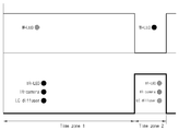
도 3은 본 발명에 따른 터치인식장치의 각 부품 동작 타이밍을 나타내는 도이다.1 and 2 schematically illustrate a display device employing the touch recognition device of the present invention,
3 is a diagram showing the operation timing of each component of the touch recognition apparatus according to the present invention.
이하에서는 첨부도면을 참조하여 본 발명에 대해 상세히 설명한다. 이하 실시예에서는 본 발명의 사상과 직접적인 관련이 있는 구성들에 관해서만 설명하며, 그 외의 구성에 관해서는 설명을 생략한다. 그러나, 본 발명의 사상이 적용된 장치 또는 시스템을 구현함에 있어서, 이와 같이 설명이 생략된 구성이 불필요함을 의미하는 것이 아님을 밝힌다. 도면에 표현된 동일한 참조 번호는 동일한 구성 요소를 나타낸다.Hereinafter, the present invention will be described in detail with reference to the accompanying drawings. In the following embodiments, only configurations directly related to the concept of the present invention will be described, and description of other configurations will be omitted. However, it is to be understood that, in the implementation of the apparatus or system to which the spirit of the present invention is applied, it is not meant that the configuration omitted from the description is unnecessary. Like reference numerals in the drawings denote like elements.
도 1은 본 발명에 따른 터치인식기술을 채용한 디스플레이장치(100)의 구조를 개략적으로 나타낸 도이다. 도 1에 나타낸 바와 같이, 디스플레이장치(100)는 영상을 표시하는 영상스크린(110), 백라이트(120), 터치인식부(130), 광확산과 광투과 동작하는 확산투과부(140), 및 상기 확산투과부(140)의 광확산과 광투과 동작을 수행하도록 구동하는 구동부(150)를 포함할 수 있다.FIG. 1 schematically shows a structure of a
상기 영상스크린(110)은 표시패널(112)과 보호패널(114)을 포함할 수 있다.The
표시패널(112)은 영상신호를 표시할 수 있다. 표시패널(112)의 구현 방식은 한정되지 않는 바, 액정(liquid crystal), 발광 다이오드(light-emitting diode), 유기발광 다이오드(organic light-emitting diode) 등의 다양한 디스플레이 패널로 구현될 수 있다.The
표시패널(112)는 구현 방식에 따라서 부가적인 구성을 추가적으로 포함할 수 있다. 예를 들면, 표시패널(112)는 액정 방식인 경우, 편광특성 및 조명광의 집광특성에 따라서 프리즘 필름, 편광필름, LCD셀, 컬러필터 등을 포함하고 있으며, 본 발명분야의 통상의 지식에 의해서 구현되는 것으로 일부 필름의 추가 또는 삭제가 가능하다.The
보호패널(114)은 외부로부터의 충격으로부터 표시패널(112)을 보호하고, 사용자의 터치에 의해 표시패널(112)이 오염되는 것을 방지하기 위한 것이다.The
백라이트(120)는 백색광을 방출하는 복수의 W-LED(122), 반사 또는 산란하는 광을 반사하여 광효율을 향상시키는 반사판(124)을 포함할 수 있다. 물론 백라이트(120)의 구성은 상술한 부품들 외에 DBEF 시트(dual brightness enhance film)(미도시), 프리즘시트(미도시), 도광판(미도시) 등을 더 포함할 수 있다.The
터치인식부(130)는 적외선을 방출하는 복수의 IR-LED(132) 및 영상스크린(110)에서 반사 또는 입력된 적외선을 인식하는 IR-카메라(134)를 포함할 수 있다.The
IR-LED(132)는 적외선을 영상스크린을 향해 방출하며, 방출된 적외선은 영상스크린에 접촉 또는 접근하는 물체에 의해 반사되어 되돌아온다. 만일 터치대상이 손가락이나 물체가 아닌 적외선 펜(미도시)을 사용할 경우 IR-LED(132)는 생략하는 것도 가능하다. The IR-
IR-카메라(134)는 상기 IR-LED(132)가 방출하여 물체로부터 반사된 적외선이나 외부 도구 예를 들면 IR펜(미도시)에서 입력된 적외선을 인식하여 물체나 IR펜의 위치를 정확하게 인식할 수 있다. The IR-
확산투과부(140)는 백라이트(120)와의 사이에 IR-카메라(134)가 배치될 수 있도록 IR-카메라(134)로부터 소정 간격 이격시켜 배치할 수 있다.The
액정물질(146)을 포함하는 패널의 일면 배치된 제1투명전극(142)과 패널 반대면에 배치된 제2투명전극(144)를 포함한다.A first
액정물질(146)은 전압인가에 따라 액정분자의 배열이 변화하는 물질로서 네마틱 액정을 포함할 수 있다.The
제1 및 제2 투명전극(142,144))은 패널의 양면에는 기상 증착법 등에 의해 형성될 수 있다. 제1 및 제2투명전극(142,144)은 ITO(Indium Tin Oxide), IZO(Indium Zinc Oxide) 또는 투명한 도전성 폴리머류 등을 이용하여 형성할 수 있다.The first and second
확산투과부(140)는 제1 및 제2투명전극(142,144)에 전압을 인가하면, 액정물질(146)의 분자 배열의 뒤틀림 각도가 변화하여 광이나 적외선이 투과할 수 있는 상태로 변화하고, 인가하던 전압을 차단하면 액정물질(146)의 분자 배열의 뒤틀림이 원래 위치로 되돌아와 광을 산란시킬 수 있다. 이때, 액정물질(146)의 분자는 인가되는 전압에 따라 적절한 각도로 배열하여 광투과와 광확산을 수행할 수 있도록 하여야 한다.When the voltage is applied to the first and second
구동부(150)는 상기 확산투과부(140)의 제1 및 제2투명전극(142,144)에 전압을 인가하기 위한 회로로서, 영상스크린(110)에 표시하는 영상 프레임 단위로 동작시킬 수 있다. 즉, 영상신호를 60 Hz나 120Hz로 표시하는 경우, 구동부(150)는 제1 및 제2투명전극(142,144)에 전압을 인가를 60 Hz나 120Hz로 연동하여 온/오프(ON/OFF) 동작시킬 수 있다. 따라서, 구동부(150)는 60분의1 초 또는 120분의1초에 한번씩 온/오프 스위칭 동작을 반복적으로 수행할 수 있다. 물론 구동부(150)는 2 이상의 프레임 단위로 온/오프 스위칭 동작을 반복적으로 수행하는 것도 가능하다.The
도 1에 나타낸 디스플레이장치(100)는 구동부(150)가 확산투과부(140)의 제1 및 제2투명전극(142,144)에 전압을 인가하지 않은 상태로서, 확산투과부(140)는 광을 확산시키는 역할을 한다. 이때, 확산투과부(140)가 확산 기능을 하는 상태에서는 IR-LED(1320와 IR-카메라(134)는 확산투과부(140)의 방해에 의해 제기능을 발휘할 수 없기 때문에 오프(OFF)시키고, 영상표시를 위한 백생광을 방출하는 W-LED(122)는 동작시킨다.In the
도 2에 나타낸 디스플레이장치(100)는 구동부(150)가 확산투과부(140)의 제1 및 제2투명전극(142,144)에 전압을 인가한 상태로서, 확산투과부(140)는 광이나 적외선을 투과시키는 역할을 한다. 이때, 확산투과부(140)가 투과 기능을 하는 상태에서는 IR-LED(132)와 IR-카메라(134)는 확산투과부(140)의 방해 없이 제기능을 발휘할 수 있기 때문에 온(ON)시키고, 영상표시를 위한 백생광을 방출하는 W-LED(122)는 오프시킨다.2, the driving
도 3은 본 발명에 따른 구동부(150)의 확산투과부(140) 구동 타이밍을 나타내는 도이다.FIG. 3 is a diagram illustrating a timing of driving the
도 3에 나타낸 바와 같이, 영상스크린(110)에 영상을 표시하는 시간영역 1(time zone 1)에서는 영상표시를 위한 백색광을 방출하는 W-LED(122)를 동작시키고, IR-LED(132, IR-카메라(134) 및 확산투과부(140)는 오프시킨다. 따라서, 시간영역 1에서는 정상적으로 영상을 표시할 수 있으며, 확산투과부(140)의 확산기능에 따라 백라이트(120)가 동작하더라도 IR-카메라(134)는 감춰질 수 있다. 따라서, IR-카메라(134)에 의한 화면 얼룩 발생을 방지할 수 있다.3, a W-
영상스크린(110)에 영상을 표시하지 않는 시간영역 2(time zone 2)에서는 영상표시를 위한 백색광을 방출하는 W-LED(122)를 동작시키고, IR-LED(132, IR-카메라(134) 및 확산투과부(140)(구동부)는 온시킨다. 따라서, 시간영역 2에서는 영상 표시를 위한 광원을 발생하지 않으며, 확산투과부(140)의 투과기능에 따라 IR-LED(132)의 방출 적외선이 확산투과부(140)를 투과하여 영상스크린(110)에 도달하고, 영상스크린(110)에 접촉 또는 접근하는 물체(손가락)에서 반사된 적외선도 확산투과부(140)를 투과하여 IR-카메라(134)로 수신될 수 있다. 이때, 시간영역2는 영상 신호 1프레임 내의 일부분에 포함될 수 있다. 즉, 본 발명에 따른 터치인식방법은 매우 짧은 주기, 예를 들면 60분의1 초 또는 120분의 1초 마다 반복적으로 적외선 인식을 위한 스위칭 동작을 수행함으로써 사용자는 이를 시각적으로 전혀 느낄 수 없다. 또한, 영상스크린에 접촉하는 물체가 영상스크린 접촉 또는 접근하는 시간이 60분의1 초 또는 120분의 1초보다 짧지 않는 한 적외선 카메라의 터치인식의 실패는 발생할 수 없다. The W-
상기한 실시예는 예시적인 것에 불과한 것으로, 당해 기술 분야의 통상의 지식을 가진 자라면 다양한 변형 및 균등한 타 실시예가 가능하다. 따라서, 본 발명의 진정한 기술적 보호범위는 하기의 특허청구범위에 기재된 발명의 기술적 사상에 의해 정해져야 할 것이다.The above-described embodiments are merely illustrative, and various modifications and equivalents may be made by those skilled in the art. Accordingly, the true scope of protection of the present invention should be determined by the technical idea of the invention described in the following claims.
100: 디스플레이장치
110: 영상스크린
120: 백라이트
130: 터치인식부
140: 확산투과부
150: 구동부100: display device
110: Video screen
120: Backlight
130: Touch recognition unit
140: diffusion transmitting portion
150:
Claims (17)
영상을 표시하는 영상스크린;
상기 영상스크린을 향해 광을 방출하는 광원;
상기 영상스크린의 배면에 배치되고, 상기 영상스크린에 접근 또는 접촉하는 물체로부터 반사 또는 입력된 적외선을 수신하는 카메라;
상기 영상 스크린과 카메라 사이에 배치되고, 상기 광원의 광방출 시에는 방출광을 확산시키고, 상기 광원의 광 미방출 시에는 상기 적외선을 투과시키는 확산투과부를 포함하는 것을 특징으로 하는 터치입력장치.
In the touch recognition device,
A video screen for displaying video;
A light source emitting light toward the image screen;
A camera disposed on a back surface of the image screen and receiving infrared rays reflected or input from an object approaching or contacting the image screen;
And a diffusion transmitting unit which is disposed between the image screen and the camera and diffuses the emitted light when the light source emits light and transmits the infrared light when the light source emits no light.
상기 영상스크린의 배면에 배치되어 적외선을 방출하는 적외선 방출부를 더 포함하는 것을 특징으로 터치인식장치.
The method according to claim 1,
And an infrared ray emitting unit disposed on a rear surface of the image screen and emitting infrared rays.
상기 적외선방출부, 카메라 및 확산투과부는 상기 광원이 광을 방출하는 동안에는 동작하지 않는 것을 특징으로 하는 터치인식장치.
3. The method of claim 2,
Wherein the infrared ray emitting portion, the camera, and the diffusion transmitting portion are not operated while the light source emits light.
상기 적외선방출부, 카메라 및 확산투과부는 상기 광원이 광을 방출하지 않는 동안에 동작하는 것을 특징으로 하는 터치인식장치.
3. The method of claim 2,
Wherein the infrared ray emitting portion, the camera and the diffusion transmitting portion operate while the light source does not emit light.
액정을 포함하는 액정패널; 및
상기 액정에 전압을 인가하기 위해 상기 액정패널의 양면에 배치되는 투명전극을 포함하는 것을 특징으로 하는 터치인식장치.
The liquid crystal display device according to claim 1,
A liquid crystal panel including a liquid crystal; And
And a transparent electrode disposed on both sides of the liquid crystal panel for applying a voltage to the liquid crystal.
상기 액정패널의 양면에 배치되는 투명전극에 전압을 인가하는 구동부를 더 포함하는 것을 특징으로 하는 터치인식장치.
6. The method of claim 5,
Further comprising a driver for applying a voltage to the transparent electrodes disposed on both sides of the liquid crystal panel.
상기 구동부는 상기 영상스크린에 표시되는 영상 프레임 변화에 연동하여 상기 투명전극에 전압을 인가하는 것을 특징으로 하는 터치인식장치.
The method according to claim 6,
Wherein the driving unit applies a voltage to the transparent electrode in response to a change in an image frame displayed on the image screen.
상기 구동부는 적어도 하나의 영상 프레임 단위로 전압 인가 온/ 오프를 반복하는 것을 특징으로 하는 터치인식장치.
8. The method of claim 7,
Wherein the driving unit repeatedly applies voltage on / off in units of at least one image frame.
상기 영상을 표시하는 표시패널;
상기 표시 패널에 광을 공급하는 백라이트;
상기 백라이트에 배치되어, 상기 표시패널에 접촉 또는 접근하는 물체로부터 반사 또는 입력된 적외선을 감지하는 카메라; 및
상기 표시패널과 카메라 사이에 배치되고, 상기 백라이트의 광방출 시에는 방출광을 확산시키고, 상기 백라이트의 광 미방출 시에는 상기 적외선을 투과시키는 확산투과부를 포함하는 것을 특징으로 하는 디스플레이장치.
In the display device,
A display panel for displaying the image;
A backlight for supplying light to the display panel;
A camera disposed in the backlight for sensing infrared rays reflected or input from an object contacting or approaching the display panel; And
And a diffusion transmitting portion disposed between the display panel and the camera and diffusing the emitted light when the backlight is emitting light and transmitting the infrared rays when the backlight is not emitting light.
상기 확산투과부는.
전압인가에 따라 광 확산 또는 광투과 동작하는 것을 특징으로 하는 디스플레이장치.
10. The method of claim 9,
The diffusion transmitting portion includes:
And the light diffusion or light transmission operation is performed according to the voltage application.
상기 백라이트는 적외선방출부를 더 포함하는 것을 특징으로 하는 디스플레이장치.
10. The method of claim 9,
Wherein the backlight further comprises an infrared ray emitting portion.
상기 적외선방출부, 카메라 및 확산투과부는 상기 백라이트가 광을 방출하는 동안에는 동작하지 않는 것을 특징으로 하는 디스플레이장치.
12. The method of claim 11,
Wherein the infrared ray emitting portion, the camera, and the diffusion transmitting portion do not operate while the backlight emits light.
상기 적외선방출부, 카메라 및 확산투과부는 상기 백라이트가 광을 방출하지 않는 동안에 동작하는 것을 특징으로 하는 디스플레이장치.
12. The method of claim 11,
Wherein the infrared ray emitting portion, the camera, and the diffusion transmitting portion operate while the backlight does not emit light.
액정을 포함하는 액정패널; 및
상기 액정에 전압을 인가하기 위해 상기 액정패널의 양면에 배치되는 투명전극을 포함하는 것을 특징으로 하는 디스플레이장치.
11. The apparatus of claim 10, wherein the diffusion-
A liquid crystal panel including a liquid crystal; And
And a transparent electrode disposed on both sides of the liquid crystal panel to apply a voltage to the liquid crystal.
상기 액정패널의 양면에 배치되는 투명전극에 전압을 인가하는 구동부를 더 포함하는 것을 특징으로 하는 디스플레이장치.
15. The method of claim 14,
And a driving unit for applying a voltage to the transparent electrodes disposed on both surfaces of the liquid crystal panel.
상기 구동부는 상기 영상스크린에 표시되는 영상 프레임 변화에 연동하여 상기 투명전극에 전압을 인가하는 것을 특징으로 하는 디스플레이장치.
16. The method of claim 15,
Wherein the driving unit applies a voltage to the transparent electrode in response to a change in an image frame displayed on the image screen.
상기 구동부는 적어도 하나의 영상 프레임 단위로 전압 인가 온/ 오프를 반복하는 것을 특징으로 하는 디스플레이장치.17. The method of claim 16,
Wherein the driving unit repeatedly applies voltage on / off in units of at least one image frame.
Priority Applications (3)
| Application Number | Priority Date | Filing Date | Title |
|---|---|---|---|
| KR1020140028484A KR20150106232A (en) | 2014-03-11 | 2014-03-11 | A touch recognition device and display applying the same |
| EP15157650.1A EP2919101A1 (en) | 2014-03-11 | 2015-03-04 | Touch recognition device and display apparatus using the same |
| US14/644,869 US20150261384A1 (en) | 2014-03-11 | 2015-03-11 | Touch recognition device and display apparatus using the same |
Applications Claiming Priority (1)
| Application Number | Priority Date | Filing Date | Title |
|---|---|---|---|
| KR1020140028484A KR20150106232A (en) | 2014-03-11 | 2014-03-11 | A touch recognition device and display applying the same |
Publications (1)
| Publication Number | Publication Date |
|---|---|
| KR20150106232A true KR20150106232A (en) | 2015-09-21 |
Family
ID=52672165
Family Applications (1)
| Application Number | Title | Priority Date | Filing Date |
|---|---|---|---|
| KR1020140028484A KR20150106232A (en) | 2014-03-11 | 2014-03-11 | A touch recognition device and display applying the same |
Country Status (3)
| Country | Link |
|---|---|
| US (1) | US20150261384A1 (en) |
| EP (1) | EP2919101A1 (en) |
| KR (1) | KR20150106232A (en) |
Cited By (1)
| Publication number | Priority date | Publication date | Assignee | Title |
|---|---|---|---|---|
| WO2020101324A1 (en) * | 2018-11-15 | 2020-05-22 | Samsung Electronics Co., Ltd. | Display apparatus and method of controlling the same |
Families Citing this family (2)
| Publication number | Priority date | Publication date | Assignee | Title |
|---|---|---|---|---|
| CN108594524B (en) * | 2018-04-26 | 2021-04-13 | 京东方科技集团股份有限公司 | Display device |
| CN110780487A (en) * | 2019-11-12 | 2020-02-11 | 广州视源电子科技股份有限公司 | Display and electronic equipment |
Family Cites Families (7)
| Publication number | Priority date | Publication date | Assignee | Title |
|---|---|---|---|---|
| US20050122308A1 (en) * | 2002-05-28 | 2005-06-09 | Matthew Bell | Self-contained interactive video display system |
| US20090219253A1 (en) * | 2008-02-29 | 2009-09-03 | Microsoft Corporation | Interactive Surface Computer with Switchable Diffuser |
| US8674965B2 (en) * | 2010-11-18 | 2014-03-18 | Microsoft Corporation | Single camera display device detection |
| US9298318B2 (en) * | 2010-12-01 | 2016-03-29 | Smart Technologies Ulc | Interactive input system and method |
| US8665244B2 (en) * | 2011-02-22 | 2014-03-04 | Microsoft Corporation | Optical touch detection |
| US9262011B2 (en) * | 2011-03-30 | 2016-02-16 | Smart Technologies Ulc | Interactive input system and method |
| KR102081733B1 (en) * | 2012-09-10 | 2020-04-16 | 삼성디스플레이 주식회사 | Method of driving a display panel, display panel driving apparatus for performing the method and display apparatus having the display panel driving apparatus |
-
2014
- 2014-03-11 KR KR1020140028484A patent/KR20150106232A/en not_active Application Discontinuation
-
2015
- 2015-03-04 EP EP15157650.1A patent/EP2919101A1/en not_active Withdrawn
- 2015-03-11 US US14/644,869 patent/US20150261384A1/en not_active Abandoned
Cited By (2)
| Publication number | Priority date | Publication date | Assignee | Title |
|---|---|---|---|---|
| WO2020101324A1 (en) * | 2018-11-15 | 2020-05-22 | Samsung Electronics Co., Ltd. | Display apparatus and method of controlling the same |
| US11095844B2 (en) | 2018-11-15 | 2021-08-17 | Samsung Electronics Co., Ltd. | Display apparatus and method of controlling the same |
Also Published As
| Publication number | Publication date |
|---|---|
| EP2919101A1 (en) | 2015-09-16 |
| US20150261384A1 (en) | 2015-09-17 |
Similar Documents
| Publication | Publication Date | Title |
|---|---|---|
| CN101989155B (en) | Optical position detection apparatus and display apparatus having position detection function | |
| US9830019B2 (en) | Touch-sensing LCD panel | |
| US8884900B2 (en) | Touch-sensing display apparatus and electronic device therewith | |
| US8339373B2 (en) | Touch panel display with infrared light source | |
| US8259240B2 (en) | Multi-touch sensing through frustrated total internal reflection | |
| EP2325735A2 (en) | Multi-touch detecting apparatus and method for LCD display apparatus | |
| US8624810B2 (en) | Liquid crystal display to which infrared rays source is applied and multi-touch system using the same | |
| US20110234535A1 (en) | Touched position identification method | |
| US20130222353A1 (en) | Prism illumination-optic | |
| US8493365B2 (en) | Optical touch display apparatus | |
| EP2188701A2 (en) | Multi-touch sensing through frustrated total internal reflection | |
| US9310918B2 (en) | Touch display having a reflective type display screen | |
| KR20090026957A (en) | Image display device including touch panel | |
| US20140092068A1 (en) | Optical touch panel and brightness control method thereof | |
| KR101374418B1 (en) | Multi-touch device | |
| JP3156727U (en) | Optical contact module | |
| CN109284026B (en) | Touch type display device and method for sensing touch | |
| KR20180085423A (en) | Display device | |
| US20110273403A1 (en) | Photo-sensing lcd touch device | |
| KR20150106232A (en) | A touch recognition device and display applying the same | |
| US8982100B2 (en) | Interactive input system and panel therefor | |
| JP2022511133A (en) | In-screen fingerprint identification device and electronic devices | |
| JP2015141499A (en) | display device | |
| Izadi et al. | Thinsight: a thin form-factor interactive surface technology | |
| CN101825797A (en) | Photo induction touch-control liquid crystal display device |
Legal Events
| Date | Code | Title | Description |
|---|---|---|---|
| WITN | Application deemed withdrawn, e.g. because no request for examination was filed or no examination fee was paid |