KR20150057321A - Dual viewing film and dual view display apparatus using that - Google Patents
Dual viewing film and dual view display apparatus using that Download PDFInfo
- Publication number
- KR20150057321A KR20150057321A KR1020130140530A KR20130140530A KR20150057321A KR 20150057321 A KR20150057321 A KR 20150057321A KR 1020130140530 A KR1020130140530 A KR 1020130140530A KR 20130140530 A KR20130140530 A KR 20130140530A KR 20150057321 A KR20150057321 A KR 20150057321A
- Authority
- KR
- South Korea
- Prior art keywords
- light
- dual
- prism
- light guide
- guide plate
- Prior art date
Links
Images


Classifications
-
- G—PHYSICS
- G02—OPTICS
- G02B—OPTICAL ELEMENTS, SYSTEMS OR APPARATUS
- G02B30/00—Optical systems or apparatus for producing three-dimensional [3D] effects, e.g. stereoscopic images
- G02B30/20—Optical systems or apparatus for producing three-dimensional [3D] effects, e.g. stereoscopic images by providing first and second parallax images to an observer's left and right eyes
- G02B30/26—Optical systems or apparatus for producing three-dimensional [3D] effects, e.g. stereoscopic images by providing first and second parallax images to an observer's left and right eyes of the autostereoscopic type
- G02B30/30—Optical systems or apparatus for producing three-dimensional [3D] effects, e.g. stereoscopic images by providing first and second parallax images to an observer's left and right eyes of the autostereoscopic type involving parallax barriers
-
- G—PHYSICS
- G02—OPTICS
- G02B—OPTICAL ELEMENTS, SYSTEMS OR APPARATUS
- G02B3/00—Simple or compound lenses
- G02B3/0006—Arrays
- G02B3/0037—Arrays characterized by the distribution or form of lenses
-
- G—PHYSICS
- G02—OPTICS
- G02B—OPTICAL ELEMENTS, SYSTEMS OR APPARATUS
- G02B5/00—Optical elements other than lenses
- G02B5/04—Prisms
- G02B5/045—Prism arrays
-
- G—PHYSICS
- G02—OPTICS
- G02B—OPTICAL ELEMENTS, SYSTEMS OR APPARATUS
- G02B6/00—Light guides; Structural details of arrangements comprising light guides and other optical elements, e.g. couplings
- G02B6/0001—Light guides; Structural details of arrangements comprising light guides and other optical elements, e.g. couplings specially adapted for lighting devices or systems
- G02B6/0011—Light guides; Structural details of arrangements comprising light guides and other optical elements, e.g. couplings specially adapted for lighting devices or systems the light guides being planar or of plate-like form
- G02B6/0033—Means for improving the coupling-out of light from the light guide
- G02B6/005—Means for improving the coupling-out of light from the light guide provided by one optical element, or plurality thereof, placed on the light output side of the light guide
- G02B6/0053—Prismatic sheet or layer; Brightness enhancement element, sheet or layer
-
- G—PHYSICS
- G02—OPTICS
- G02B—OPTICAL ELEMENTS, SYSTEMS OR APPARATUS
- G02B6/00—Light guides; Structural details of arrangements comprising light guides and other optical elements, e.g. couplings
- G02B6/0001—Light guides; Structural details of arrangements comprising light guides and other optical elements, e.g. couplings specially adapted for lighting devices or systems
- G02B6/0011—Light guides; Structural details of arrangements comprising light guides and other optical elements, e.g. couplings specially adapted for lighting devices or systems the light guides being planar or of plate-like form
- G02B6/0075—Arrangements of multiple light guides
- G02B6/0076—Stacked arrangements of multiple light guides of the same or different cross-sectional area
-
- H—ELECTRICITY
- H04—ELECTRIC COMMUNICATION TECHNIQUE
- H04N—PICTORIAL COMMUNICATION, e.g. TELEVISION
- H04N13/00—Stereoscopic video systems; Multi-view video systems; Details thereof
- H04N13/30—Image reproducers
- H04N13/302—Image reproducers for viewing without the aid of special glasses, i.e. using autostereoscopic displays
- H04N13/305—Image reproducers for viewing without the aid of special glasses, i.e. using autostereoscopic displays using lenticular lenses, e.g. arrangements of cylindrical lenses
-
- H—ELECTRICITY
- H04—ELECTRIC COMMUNICATION TECHNIQUE
- H04N—PICTORIAL COMMUNICATION, e.g. TELEVISION
- H04N13/00—Stereoscopic video systems; Multi-view video systems; Details thereof
- H04N13/30—Image reproducers
- H04N13/302—Image reproducers for viewing without the aid of special glasses, i.e. using autostereoscopic displays
- H04N13/32—Image reproducers for viewing without the aid of special glasses, i.e. using autostereoscopic displays using arrays of controllable light sources; using moving apertures or moving light sources
-
- H—ELECTRICITY
- H04—ELECTRIC COMMUNICATION TECHNIQUE
- H04N—PICTORIAL COMMUNICATION, e.g. TELEVISION
- H04N13/00—Stereoscopic video systems; Multi-view video systems; Details thereof
- H04N13/30—Image reproducers
- H04N13/302—Image reproducers for viewing without the aid of special glasses, i.e. using autostereoscopic displays
- H04N13/31—Image reproducers for viewing without the aid of special glasses, i.e. using autostereoscopic displays using parallax barriers
-
- H—ELECTRICITY
- H04—ELECTRIC COMMUNICATION TECHNIQUE
- H04N—PICTORIAL COMMUNICATION, e.g. TELEVISION
- H04N13/00—Stereoscopic video systems; Multi-view video systems; Details thereof
- H04N13/30—Image reproducers
- H04N2013/40—Privacy aspects, i.e. devices showing different images to different viewers, the images not being viewpoints of the same scene
- H04N2013/403—Privacy aspects, i.e. devices showing different images to different viewers, the images not being viewpoints of the same scene the images being monoscopic
-
- H—ELECTRICITY
- H04—ELECTRIC COMMUNICATION TECHNIQUE
- H04N—PICTORIAL COMMUNICATION, e.g. TELEVISION
- H04N13/00—Stereoscopic video systems; Multi-view video systems; Details thereof
- H04N13/30—Image reproducers
- H04N2013/40—Privacy aspects, i.e. devices showing different images to different viewers, the images not being viewpoints of the same scene
- H04N2013/405—Privacy aspects, i.e. devices showing different images to different viewers, the images not being viewpoints of the same scene the images being stereoscopic or three dimensional
Landscapes
- Physics & Mathematics (AREA)
- General Physics & Mathematics (AREA)
- Optics & Photonics (AREA)
- Multimedia (AREA)
- Signal Processing (AREA)
- Engineering & Computer Science (AREA)
- Liquid Crystal (AREA)
- Planar Illumination Modules (AREA)
- Devices For Indicating Variable Information By Combining Individual Elements (AREA)
- Optical Elements Other Than Lenses (AREA)
- Stereoscopic And Panoramic Photography (AREA)
- Fittings On The Vehicle Exterior For Carrying Loads, And Devices For Holding Or Mounting Articles (AREA)
- Transforming Electric Information Into Light Information (AREA)
- Testing, Inspecting, Measuring Of Stereoscopic Televisions And Televisions (AREA)
Abstract
Description
본 발명은 듀얼 뷰잉 필름(Dual Viewing Film)과 이를 이용한 듀얼 뷰 디스플레이(Dual View Display) 장치에 관한 것으로서, 상세하게는 프리즘 입력층 및 렌즈 출력층을 구비하여 빛을 듀얼 뷰 디스플레이의 법선 축에서 벗어난 좌측 또는 우측 방향의 시청자를 향하도록 굴절시키는 듀얼 뷰잉 필름과 이를 이용한 듀얼 뷰 디스플레이 장치에 관한 것이다.[0001] The present invention relates to a dual viewing film and a dual view display using the same, and more particularly, to a dual viewing display having a prism input layer and a lens output layer, Or a viewer toward the right direction, and a dual view display device using the same.
내비게이션 맵, 후방 카메라 디스플레이, 자동차 제어 디스플레이, 웹-브라우징 디스플레이, 브로드캐스트 디스플레이 등의 다양한 목적을 위해, 디스플레이 시스템이 자동차에 장착되고 있다.For various purposes, such as navigation maps, rear camera displays, automotive control displays, web-browsing displays, broadcast displays, and the like, display systems are being installed in automobiles.
자동차 내비게이션 디스플레이는 특정 경로를 이용하여 운전자를 올바른 목적지로 가이드 해주는 간단한 자동차 내비게이션 기능, 후방으로 이동할 때 운전자에게 어떤 객체나 사물이 있는지를 표시하는 기능, 많은 다른 콘텐츠(영화, TV 콘텐츠 등)를 공유하는 기능과 같은 다양한 목적을 위해 차량에 널리 채택된다.The car navigation display has a simple car navigation function that guides the driver to the correct destination by using a specific route, a function to display the driver what objects or objects are present when moving backward, and a lot of other contents (movies, TV contents, etc.) And is widely adopted in vehicles for various purposes.
그러나 내비게이션 이외의 다른 많은 정보는 운전을 방해할 수 있다. 그것은 심각한 자동차 사고를 초래할 수 있다. 운전자가 운전하면서 다양한 콘텐츠를 보는 것을 방지하기 위해, 듀얼 이미지 디스플레이는 운전자와 조수석 승객 모두에 적합하다. 운전자는 단지 내비게이션 콘텐츠들을 볼 것이고, 반면, 조수석 승객들은 원하는 콘텐츠를 볼 수 있다. 즉, 자동차 내비게이션의 듀얼 이미지 디스플레이는 운전자에게 내비게이션 이미지를 표시하고, 반면, 조수석 승객에게는 다른 콘텐츠를 표시한다.However, many other information besides navigation can interfere with driving. It can cause serious car accidents. To prevent the driver from seeing various content while driving, the dual image display is suitable for both driver and passenger seat passengers. The driver will only see the navigation content, while the passenger seat passengers will be able to view the desired content. That is, the dual image display of the car navigation displays the navigation image to the driver, while the passenger of the passenger seat displays the other content.
전형적인 듀얼 이미지 디스플레이는 이미지를 좌측 이미지와 우측 이미지로 분할하기 위해 시차 장벽 디스플레이(Parallax Barrier Display)로 구현된다.A typical dual image display is implemented with a Parallax Barrier Display to divide the image into left and right images.
도 1 및 도 2는 자동차에 장착된 종래의 듀얼 이미지 디스플레이에 대한 설명도이다.1 and 2 are explanatory views of a conventional dual image display mounted on a vehicle.
이미지 분할과 같은 시차 장벽 기능의 전형적인 예가 도 1 및 도 2에 도시되어 있다.A typical example of a parallax barrier function such as image segmentation is shown in Figs. 1 and 2. Fig.
도 1에 도시된 바와 같이, 종래의 듀얼 이미지 디스플레이는 스크린(110) 및 시차 장벽(120)으로 구성된다. 시차 장벽(120)은 의도적으로 스크린(110)의 좌측 이미지(111)와 우측 이미지(112)를 분할하기 위한 장벽으로 이루어진다. LCD 패널로부터의 스크린(110)의 빛이 시차 장벽(120)에 의해 개별적으로 분할되어 좌측(101) 및 우측(102)에 도달한다.As shown in FIG. 1, a conventional dual-image display comprises a
대안적으로, 도 2에 도시된 바와 같이, 종래의 듀얼 이미지 디스플레이는 스크린(110) 및 볼록 렌즈(220)로 구성된다. 볼록 렌즈(220)는 스크린(110)의 좌측 이미지(212)와 우측 이미지(211)를 굴절시키는 렌즈로 이루어진다. 스크린(110)으로부터 빛이 볼록 렌즈(220)에 의해 개별적으로 굴절되어 좌측(201) 및 우측(202)에 도달한다.Alternatively, as shown in FIG. 2, a conventional dual-image display consists of a
도 1 및 도 2에 도시된 기술은 좌측 및 우측 뷰잉 존(Viewing Zone)에서 각각의 위치에 해당하는 하나의 시야(View)를 보여준다. 따라서 시청자는 특수한 안경들의 사용 없이 시차 모션과 양안 스테레오를 경험한다. 이러한 디스플레이 유형의 단점은 LCD 패널이 라인별로 얽힌 2개의 좌측 및 우측 이미지를 디스플레이하기 때문에 해상도가 반으로 감소하는 것이다.The techniques shown in FIGS. 1 and 2 show one view corresponding to each position in the left and right viewing zones. Thus viewers experience parallax motion and binocular stereo without the use of special glasses. A disadvantage of this type of display is that the resolution is halved because the LCD panel displays two left and right images tangled line by line.
도 3은 종래의 시차 장벽 디스플레이에 의한 좌측 및 우측 시야에 대한 예시도이다.3 is an exemplary view of left and right viewing fields by a conventional parallax barrier display.
종래의 듀얼 뷰 디스플레이는 시차 장벽(320)을 사용하거나 렌즈 모양의 렌즈 또는 프리즘 렌즈를 사용하는 공간 멀티플렉싱(Spatial Multiplexing) 방식을 이용한다. 이러한 공간 멀티플렉싱 방식은 원본 이미지(310)의 해상도를 반으로 감소시킨다. 이는 원본 이미지(310)가 듀얼 뷰 디스플레이를 구현하기 위해 공간적으로 분할되기 때문이다. 이것은 공간 멀티플렉싱의 듀얼 뷰 디스플레이가 기술적으로 용이하게 채택되더라도 시차 장벽 디스플레이로 해결될 수 없는 단점 중의 하나이다. Conventional dual view displays employ a spatial multiplexing scheme using a
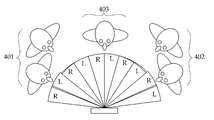
도 4는 종래의 시차 장벽 방식이 이용된 듀얼 뷰 디스플레이를 통해 좌측, 중앙 및 우측 시청자가 바라보는 이미지에 대한 설명도이다.4 is an explanatory view of images viewed by left, center and right viewers through a dual view display using a conventional parallax barrier method.
종래의 시차 장벽이 이용된 듀얼 뷰 디스플레이는 전체 좌측(L) 이미지와 우측(R) 이미지를 교대로 좌측 사용자(401), 중앙 사용자(403) 및 우측 사용자(402)에게 표시한다.The dual view display using the conventional parallax barriers alternately displays the left (L) image and the right (R) image to the left user (401), the central user (403), and the right user (402).
본 발명은 시차 장벽 및 렌즈 타입의 듀얼 이미지 디스플레이로부터의 이슈를 해결한다. 본 발명은 높은 재생률 패널 조합을 가진 필드 연속(Sequential) 양방향 백라이트를 이용하여 이미지 해상도 감소에 대한 문제를 해결한다.The present invention addresses the issue from dual image displays of parallax barrier and lens type. The present invention solves the problem of image resolution reduction using a field sequential bi-directional backlight with a high refresh rate panel combination.
본 발명은 좌우 측면 발광 광원(예컨대, LED 광원), 구조화된 도광판, 기판의 하부에 프리즘 패턴을 가진 렌즈 모양의 듀얼 뷰잉 필름 및 높은 재생률을 가진 디스플레이 패널(예컨대, LCD 패널)을 포함함으로써, 좌측 및 우측 방향의 시청자에게 해상도가 감소하지 않은 서로 다른 이미지를 디스플레이할 수 있는 듀얼 뷰잉 필름과 이를 이용한 듀얼 뷰 디스플레이 장치를 제공한다. 3D 디스플레이는 3D 효과를 실현하기 위해 높은 재생률 LCD 패널을 이용한다. 전형적인 재생률은 3D LCD TV의 대부분 셔터 안경들이 이용하는 120Hz 및 240Hz이다. 본 발명은 이러한 높은 재생률을 필수적으로 요구하지 않는다. 본 발명은 3D 디스플레이가 아니기 때문에 90Hz 이상 120Hz 미만의 재생률 패널이 충분하다.The present invention includes a left and right side luminescent light source (e.g., LED light source), a structured light guide plate, a lens-like dual viewing film having a prism pattern at the bottom of the substrate, and a display panel And a dual view film capable of displaying different images in which resolution is not reduced to a viewer in the right direction, and a dual view display device using the same. 3D displays use high refresh rate LCD panels to realize 3D effects. Typical refresh rates are 120Hz and 240Hz for most shutter glasses in 3D LCD TVs. The present invention does not necessarily require such a high regeneration rate. Since the present invention is not a 3D display, a refresh rate panel of 90 Hz or more and 120 Hz or less is sufficient.
또한, 본 발명은, 듀얼 뷰 디스플레이 장치에서 크로스토크가 발생하는 경우, 프리즘 입력층의 프리즘 피치와 렌즈 출력층의 렌즈 피치 간의 피크-투-피크 편차를 가진 듀얼 뷰잉 필름을 통해 크로스토크를 최소화하고자 한다.The present invention also attempts to minimize crosstalk through a dual viewing film having a peak-to-peak deviation between the prism pitch of the prism input layer and the lens pitch of the lens output layer when crosstalk occurs in a dual view display device .
또한, 본 발명은, 피치 편차를 가진 듀얼 뷰잉 필름으로 인해 비대칭적인 빛의 출력 분포가 발생하는 경우, 서로 다른 밝기를 가진 광원을 이용하여 대칭적인 빛의 출력 분포를 가지는 듀얼 뷰 디스플레이 장치를 제공하고자 한다.The present invention also provides a dual view display device having a symmetrical light output distribution using a light source having different brightness when an asymmetrical light output distribution occurs due to a dual viewing film having a pitch deviation do.
또한, 본 발명은, 좌측 및 우측 광원의 밝기 강도가 조절되지 않는 경우, 동일한 밝기 강도를 가진 광원을 이용하더라도 제1 및 제2 도광판으로 이루어진 듀얼 도광판을 이용하여 대칭적인 빛의 출력 분포를 가지는 듀얼 뷰 디스플레이 장치를 제공하고자 한다.The present invention also provides a dual-mode light source having a symmetrical light output distribution using a dual light guide plate made of first and second light guide plates even when a light source having the same brightness intensity is used, View display device.
이를 위하여, 본 발명의 제1 측면에 따르면, 듀얼 뷰 디스플레이에서의 듀얼 뷰잉 필름에 있어서, 기판층; 상기 기판층 하부에 프리즘 꼭지각 및 프리즘 피치를 가지는 복수의 프리즘이 형성되는 프리즘 입력층; 및 상기 기판층 상부에 렌즈 피치와 렌즈 곡률 반경을 가지는 복수의 렌즈가 형성되는 렌즈 출력층을 포함하고, 상기 프리즘 입력층의 좌측 또는 우측으로 입력된 빛이 반사되고, 상기 반사된 빛이 상기 렌즈 출력층을 통해 상기 듀얼 뷰 디스플레이의 법선 축에서 벗어난 좌측 또는 우측 방향의 시청자를 향하도록 굴절되는 것을 특징으로 하는 듀얼 뷰잉 필름이 제공될 수 있다.To this end, according to a first aspect of the present invention, there is provided a dual viewing film in a dual view display comprising: a substrate layer; A prism input layer in which a plurality of prisms having a prism apex angle and a prism pitch are formed under the substrate layer; And a lens output layer in which a plurality of lenses having a lens pitch and a radius of curvature of lens are formed on the substrate layer, wherein light input to the left or right of the prism input layer is reflected, Is directed to a viewer in the left or right direction outside the normal axis of the dual view display.
상기 렌즈 출력층에서 굴절된 빛이 상기 듀얼 뷰 디스플레이의 법선 축에서 ±10도 이상 벗어난 좌측 또는 우측 방향의 시청자를 향하는 것을 특징으로 한다.And the light refracted in the lens output layer is directed to the viewer in the left or right direction deviated by more than +/- 10 degrees from the normal axis of the dual view display.
상기 프리즘 입력층은, 80도 내지 90도 사이의 프리즘 꼭지각과 40um 내지 60um 사이의 프리즘 피치를 가지는 복수의 프리즘이 형성되는 것을 특징으로 한다.The prism input layer is characterized in that a plurality of prisms having a prism apex angle between 80 degrees and 90 degrees and a prism pitch between 40 pm and 60 pm are formed.
상기 듀얼 뷰 디스플레이의 크로스토크가 기설정된 값 이하로 감소하도록, 상기 프리즘 입력층의 프리즘 피치와 상기 렌즈 출력층의 렌즈 피치의 피크 중심이 서로 어긋나있는 것을 특징으로 한다.The prism pitch of the prism input layer and the peak center of the lens pitch of the lens output layer are shifted from each other such that the crosstalk of the dual view display is reduced to a predetermined value or less.
상기 프리즘 입력층의 프리즘 피치와 상기 렌즈 출력층의 렌즈 피치 간의 피크-투-피크 피치 값이 0um 내지 20um 범위로 어긋나는 것을 특징으로 한다.The peak-to-peak pitch value between the prism pitch of the prism input layer and the lens pitch of the lens output layer is shifted in the range of 0 um to 20 um.
한편, 본 발명의 제2 측면에 따르면, 빛의 경로를 가이드하는 도광판; 상기 도광판의 양측 에지에 인접하고, 연속적인 좌측 및 우측 타이밍에 따라 좌측 또는 우측으로 빛을 상기 도광판으로 출력하는 좌측 및 우측 광원; 상기 도광판의 하부에 위치하고, 상기 도광판으로부터 출력된 빛을 후면 반사시키는 반사면; 복수의 프리즘이 전체 하부면에 걸쳐 연속적인 프리즘 입력층과 복수의 렌즈가 전체 상부면에 걸쳐 연속적인 렌즈 출력층을 포함하고, 상기 도광판의 상부에 위치하고 상기 도광판으로부터 상기 프리즘 입력층의 좌측 또는 우측으로 입력된 빛을 반사시키고, 상기 반사된 빛을 상기 렌즈 출력층을 통해 듀얼 뷰 디스플레이의 법선 축에서 벗어난 좌측 또는 우측 방향의 시청자를 향하도록 굴절시키는 듀얼 뷰잉 필름; 및 상기 듀얼 뷰잉 필름의 상부에 위치하고, 상기 굴절된 빛을 이용하여 상기 좌측 또는 우측 방향의 시청자에게 서로 다른 이미지를 표시하는 디스플레이 패널을 포함하는 것을 특징으로 한다.According to a second aspect of the present invention, there is provided a light guide plate for guiding a light path; Left and right light sources adjacent to both side edges of the light guide plate and outputting light to the light guide plate to left or right according to successive left and right timings; A reflection surface positioned at a lower portion of the light guide plate and reflecting light output from the light guide plate backward; A plurality of prisms including a continuous prism input layer and a plurality of lenses extending over the entire lower surface and including a continuous lens output layer over the entire upper surface and disposed on the upper side of the light guide plate and extending from the light guide plate to the left or right side A dual viewing film reflecting the input light and refracting the reflected light through the lens output layer towards a viewer in the left or right direction away from the normal axis of the dual view display; And a display panel positioned on the dual viewing film and displaying different images to the viewer in the left or right direction using the refracted light.
상기 프리즘 입력층은 상기 듀얼 뷰잉 필름의 하부에 상기 좌측 및 우측 광원의 발광 방향과 수직인 패턴을 가지고, 상기 렌즈 출력층은 상기 듀얼 뷰잉 필름의 상부에 상기 좌측 및 우측 광원의 발광 방향과 수직한 패턴을 가지는 것을 특징으로 한다.Wherein the prism input layer has a pattern perpendicular to a light emitting direction of the left and right light sources at a lower portion of the dual viewing film, .
상기 듀얼 뷰잉 필름의 프리즘 입력층 및 렌즈 출력층 간의 피치 편차가 있고, 상기 좌측 및 우측 광원은 비대칭적인 빛의 분포를 가지도록 서로 다른 밝기 강도의 빛을 좌측 및 우측으로 각각 출력하는 것을 특징으로 한다.The prism input layer and the lens output layer of the dual viewing film have a pitch deviation and the left and right light sources output lights of different brightness intensities to left and right respectively so as to have an asymmetrical light distribution.
상기 도광판은, 수평 방향으로 위치한 제1 및 제2 도광판으로 이루어지고, 상기 제1 및 제2 도광판이 상기 좌측 및 우측 광원과 각각 결합되고, 상기 좌측 및 우측 광원으로부터 출력된 빛의 경로를 상기 각각 결합된 제1 및 제2 도광판을 통해 각각 가이드하는 것을 특징으로 한다.Wherein the light guide plate comprises first and second light guide plates disposed in a horizontal direction, the first and second light guide plates are respectively coupled to the left and right light sources, and the paths of light output from the left and right light sources are respectively And guided through the first and second light guide plates, respectively.
상기 제1 도광판 및 상기 제2 도광판이 각각 결합된 도광판의 상부 및 하부에 위치하고, 상기 제2 도광판의 상부 표면과 상기 제1 도광판의 하부 표면 사이에 에어 갭이 형성되는 것을 특징으로 한다.And an air gap is formed between the upper surface of the second light guide plate and the lower surface of the first light guide plate, the upper surface and the lower surface of the light guide plate having the first light guide plate and the second light guide plate respectively coupled thereto.
상기 디스플레이 패널은, 상기 좌측 또는 우측 방향의 시청자에게 서로 다른 이미지를 90Hz 이상의 재생률로 재생시켜 액정 디스플레이를 통해 표시하는 것을 특징으로 한다.The display panel reproduces different images to the viewer in the left or right direction at a refresh rate of 90 Hz or higher and displays the image through a liquid crystal display.
상기 도광판의 에지 표면은 반사면에 의해 후면 반사된 빛으로부터 생성된 크로스토크를 최소화하는 패턴 처리하는 것을 특징으로 한다.And the edge surface of the light guide plate is patterned to minimize crosstalk generated from the back-reflected light by the reflective surface.
상기 렌즈 출력층에서 굴절된 빛이 상기 듀얼 뷰 디스플레이의 법선 축에서 ±10도 이상 벗어난 좌측 또는 우측 방향의 시청자를 향하는 것을 특징으로 한다.And the light refracted in the lens output layer is directed to the viewer in the left or right direction deviated by more than +/- 10 degrees from the normal axis of the dual view display.
상기 프리즘 입력층은, 80도 내지 90도 사이의 프리즘 꼭지각과 40um 내지 60um 사이의 프리즘 피치를 가지는 복수의 프리즘이 형성되는 것을 특징으로 한다.The prism input layer is characterized in that a plurality of prisms having a prism apex angle between 80 degrees and 90 degrees and a prism pitch between 40 pm and 60 pm are formed.
상기 듀얼 뷰 디스플레이의 크로스토크가 기설정된 값 이하로 감소되도록, 상기 프리즘 입력층의 프리즘 피치와 상기 렌즈 출력층의 렌즈 피치의 피크 중심이 서로 어긋나있는 것을 특징으로 한다.The prism pitch of the prism input layer and the peak center of the lens pitch of the lens output layer are shifted from each other such that the crosstalk of the dual view display is reduced to a predetermined value or less.
상기 프리즘 입력층의 프리즘 피치와 상기 렌즈 출력층의 렌즈 피치 간의 피크-투-피크 피치 값이 0um 내지 20um 범위로 어긋나는 것을 특징으로 한다.The peak-to-peak pitch value between the prism pitch of the prism input layer and the lens pitch of the lens output layer is shifted in the range of 0 um to 20 um.
본 발명은, 높은 재생률 패널 조합을 가진 필드 연속(Sequential) 양방향 백라이트를 이용하여 이미지 해상도 감소를 해결할 수 있는 효과가 있다.The present invention has the effect of solving image resolution reduction using a field sequential bidirectional backlight with a high refresh rate panel combination.
또한, 본 발명의 실시 예들은 좌우 측면 발광 광원(예컨대, LED 광원), 구조화된 도광판, 기판의 하부에 프리즘 패턴을 가진 렌즈 모양의 듀얼 뷰잉 필름 및 높은 재생률을 가진 디스플레이 패널(예컨대, LCD 패널)을 포함함으로써, 좌측 및 우측 방향의 시청자에게 해상도가 감소하지 않은 서로 다른 이미지를 디스플레이할 수 있는 효과가 있다.In addition, the embodiments of the present invention can be applied to a display device (e.g., an LCD panel) having a left and right side emission light source (for example, LED light source), a structured light guide plate, a dual viewing film in the form of a lens having a prism pattern, It is possible to display different images in which the resolution is not reduced to the viewers in the left and right directions.
또한, 본 발명의 실시 예들은, 듀얼 뷰 디스플레이 장치에서 크로스토크가 발생하는 경우, 프리즘 입력층의 프리즘 피치와 렌즈 출력층의 렌즈 피치 간의 피크-투-피크 편차를 가진 듀얼 뷰잉 필름을 통해 크로스토크를 최소화할 수 있는 효과가 있다.Embodiments of the present invention also provide a method and apparatus for measuring crosstalk through a dual viewing film having a peak-to-peak deviation between a prism pitch of a prism input layer and a lens pitch of a lens output layer when a crosstalk occurs in a dual view display device There is an effect that can be minimized.
또한, 본 발명의 실시 예들은, 피치 편차를 가진 듀얼 뷰잉 필름으로 인해 비대칭적인 빛의 출력 분포가 발생하는 경우, 서로 다른 밝기를 가진 광원을 이용하여 대칭적인 빛의 출력 분포를 제공할 수 있는 효과가 있다.In addition, embodiments of the present invention can provide an output distribution of symmetrical light using a light source having different brightness when an asymmetrical light output distribution occurs due to a dual viewing film having a pitch deviation .
또한, 본 발명의 실시 예들은, 좌측 및 우측 광원의 밝기 강도가 조절되지 않는 경우, 동일한 밝기 강도를 가진 광원을 이용하더라도 제1 및 제2 도광판으로 이루어진 듀얼 도광판을 이용하여 대칭적인 빛의 출력 분포를 제공할 수 있는 효과가 있다.Further, in the embodiments of the present invention, when the brightness intensity of the left and right light sources is not adjusted, even if a light source having the same brightness intensity is used, a dual light guide plate composed of first and second light guide plates is used, Can be provided.
도 1 및 도 2는 자동차에 장착된 종래의 듀얼 이미지 디스플레이에 대한 설명도이다.
도 3은 종래의 시차 장벽 디스플레이에 의한 좌측 및 우측 시야에 대한 예시도이다.
도 4는 종래의 시차 장벽 방식이 이용된 듀얼 뷰 디스플레이를 통해 좌측, 중앙 및 우측 시청자가 바라보는 이미지에 대한 설명도이다.
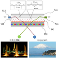
도 5a 및 도 5b는 본 발명의 실시 예에 따른 좌우 측면 발광을 이용한 듀얼 뷰 디스플레이 장치에 대한 개념도이다.
도 6은 본 발명의 실시 예에 따른 듀얼 뷰 디스플레이의 구동을 위한 LCD 패널 및 백라이트 제어 타이밍에 대한 설명도이다.
도 7은 본 발명의 실시 예에 따른 듀얼 뷰잉 필름의 구조도 및 빛 출력 각도에 대한 설명도이다.
도 8은 다양한 디스플레이 구조에서의 각도 빛 분포에 대한 코노스코프 설명도이다.
도 9는 본 발명의 실시 예에 따른 듀얼 뷰잉 필름이 적용된 듀얼 뷰 디스플레이에서의 좌우측 시야에 대한 예시도이다.
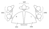
도 10 및 도 11은 본 발명의 실시 예에 따른 시간적 멀티플렉싱의 듀얼 뷰 디스플레이를 통해 좌측, 중앙 및 우측 시청자가 바라보는 이미지에 대한 설명도와 이미지에 대한 예시도이다.
도 12 및 도 13은 본 발명의 실시 예에 따른 프리즘 꼭지각 및 입력 각도에 의한 출력 각도 시뮬레이션과 출력 각도 계산 과정에 대한 설명도이다.
도 14는 본 발명의 실시 예에 따른 프리즘 입력층 및 렌즈 출력층 간의 피크 편차에 따른 크로스토크에 대한 설명도이다.
도 15는 본 발명의 실시 예에 따른 프리즘 입력층 및 렌즈 출력층 간의 피크 편차에 따른 시야각 분포 시뮬레이션에 대한 설명도이다.
도 16은 본 발명의 실시 예에 따른 프리즘 각도와 피크-투-피크 편차에 따른 광학 시뮬레이션 결과에 대한 설명도이다.
도 17은 본 발명의 듀얼 뷰잉 필름에서 발생하는 1차 및 2차 크로스토크에 대한 설명도이다.
도 18은 본 발명의 실시 예에 따른 듀얼 뷰잉 필름을 이용한 듀얼 뷰 디스플레이 장치의 구성도이다.
도 19는 본 발명에 적용된 양쪽 측면 LED들을 가진 도광판을 이용한 빛 출력 분포의 광학 시뮬레이션 결과에 대한 설명도이다.
도 20 및 도 21은 본 발명의 실시 예에 따른 두 가지 종류의 듀얼 뷰잉 필름을 이용한 광학 시뮬레이션 결과에 대한 설명도이다.
도 22 및 도 23은 본 발명의 실시 예에 따른 서로 다른 밝기 강도를 가지는 광원을 이용한 듀얼 뷰 디스플레이 장치의 빛 출력 분포에 대한 설명도이다.
도 24는 본 발명의 실시 예에 따른 듀얼 도광판을 이용한 듀얼 뷰 디스플레이 장치의 구성도이다.
도 25는 본 발명의 실시 예에 따른 동일한 광원과 결합된 듀얼 도광판에 대한 비대칭적인 광학 시뮬레이션 결과에 대한 설명도이다.
도 26은 본 발명의 실시 예에 따른 듀얼 도광판을 이용한 듀얼 뷰 디스플레이 장치에 대한 광학 시뮬레이션 결과에 대한 설명도이다.1 and 2 are explanatory views of a conventional dual image display mounted on a vehicle.
3 is an exemplary view of left and right viewing fields by a conventional parallax barrier display.
4 is an explanatory view of images viewed by left, center and right viewers through a dual view display using a conventional parallax barrier method.
5A and 5B are conceptual diagrams of a dual view display device using left and right side light emission according to an embodiment of the present invention.
6 is an explanatory diagram of an LCD panel and backlight control timing for driving a dual view display according to an embodiment of the present invention.
FIG. 7 is a diagram illustrating a structure of a dual viewing film and a light output angle according to an embodiment of the present invention.
8 is a conoscopic illustration of angular light distribution in various display structures.
FIG. 9 is an exemplary view of right and left views in a dual view display to which a dual viewing film according to an embodiment of the present invention is applied.
FIGS. 10 and 11 are illustrations of images viewed by left, center and right viewers through a dual view display of temporal multiplexing according to an embodiment of the present invention.
12 and 13 are explanatory diagrams of an output angle simulation and an output angle calculation process according to a prism apex angle and an input angle according to an embodiment of the present invention.
14 is an explanatory diagram of crosstalk according to a peak deviation between a prism input layer and a lens output layer according to an embodiment of the present invention.
15 is an explanatory diagram of simulation of a viewing angle distribution according to a peak deviation between a prism input layer and a lens output layer according to an embodiment of the present invention.
16 is an explanatory diagram of optical simulation results according to a prism angle and a peak-to-peak deviation according to an embodiment of the present invention.
17 is an explanatory diagram of primary and secondary crosstalk generated in the dual viewing film of the present invention.
18 is a configuration diagram of a dual view display device using a dual viewing film according to an embodiment of the present invention.
FIG. 19 is an explanatory diagram of optical simulation results of a light output distribution using a light guide plate having both side LEDs applied to the present invention. FIG.
20 and 21 are explanatory diagrams of optical simulation results using two kinds of dual viewing films according to an embodiment of the present invention.
22 and 23 are explanatory diagrams of a light output distribution of a dual view display device using light sources having different brightness intensities according to an embodiment of the present invention.
24 is a configuration diagram of a dual view display device using a dual light guide plate according to an embodiment of the present invention.
25 is an explanatory diagram of asymmetric optical simulation results for a dual light guide plate combined with the same light source according to an embodiment of the present invention.
26 is an explanatory diagram of optical simulation results for a dual view display device using a dual light guide plate according to an embodiment of the present invention.
이하, 첨부된 도면을 참조하여 본 발명의 실시 예에 따른 실시 예를 상세하게 설명한다. 본 발명의 구성 및 그에 따른 작용 효과는 이하의 상세한 설명을 통해 명확하게 이해될 것이다. 본 발명의 상세한 설명에 앞서, 동일한 구성요소에 대해서는 다른 도면 상에 표시되더라도 가능한 동일한 부호로 표시하며, 공지된 구성에 대해서는 본 발명의 요지를 흐릴 수 있다고 판단되는 경우 구체적인 설명은 생략하기로 함에 유의한다.Hereinafter, embodiments of the present invention will be described in detail with reference to the accompanying drawings. The configuration of the present invention and the operation and effect thereof will be clearly understood through the following detailed description. Before describing the present invention in detail, the same components are denoted by the same reference symbols as possible even if they are displayed on different drawings. In the case where it is judged that the gist of the present invention may be blurred to a known configuration, do.
본 발명의 실시 예들에 따른 듀얼 이미지 디스플레이는 시차 장벽 방식의 듀얼 이미지 디스플레이에서 전형적으로 나타나는 해상도의 손실 없이 차량에서 듀얼 이미지 디스플레이를 제공한다.The dual image display according to embodiments of the present invention provides dual image display in a vehicle without loss of resolution typically exhibited in a parallax barrier dual image display.
3차원 필름은 시청자의 각각의 눈을 향하여 측면 발광 LED에서 발광된 빛을 터닝시켜 자동 스테레오스코픽 이미지를 제공한다. 이와 다르게, 본 발명의 실시 예들에 따른 듀얼 이미지 디스플레이는 필름의 프리즘 기하학적 구조에 의해, 균등하게 분산된 빛을 듀얼 이미지 디스플레이에 적합하게 생성할 수 있다. 듀얼 이미지 디스플레이는 차량에 내장된 자동차 내비게이션 디스플레이에 매우 유용하게 적용될 수 있다.The three-dimensional film turns the light emitted from the side emitting LED toward each eye of the viewer to provide an automatic stereoscopic image. Alternatively, the dual image display according to embodiments of the present invention can produce uniformly dispersed light for a dual image display, due to the prism geometry of the film. The dual image display can be very useful for car navigation displays embedded in vehicles.
종래의 자동차 내비게이션 디스플레이는 하나의 이미지를 운전자 및 승객 모두에게 제공한다. 반면, 본 발명의 실시 예들은 운전자 및 승객에게 서로 다른 이미지를 해상도 감소 없이 제공할 수 있다. 예를 들어, 운전자는 내비게이션 지도를 본다. 반면, 승객은 영화, 웹 브라우징 또는 트래픽 정보와 같은 다른 콘텐츠를 본다.Conventional car navigation displays provide an image to both the driver and passengers. On the other hand, embodiments of the present invention can provide different images to the driver and passenger without resolution reduction. For example, the driver sees a navigation map. On the other hand, passengers see other content such as movies, web browsing or traffic information.
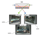
도 5a 및 도 5b는 본 발명의 실시 예에 따른 좌우 측면 발광을 이용한 듀얼 뷰 디스플레이 장치에 대한 개념도이다.5A and 5B are conceptual diagrams of a dual view display device using left and right side light emission according to an embodiment of the present invention.
도 5a 및 도 5b에 도시된 바와 같이, 듀얼 뷰 디스플레이(500)는 좌우 측면 발광 LED(511 및 512), 반사면(520), 패턴을 가진 도광판(530), 듀얼 뷰잉 필름(Dual Viewing Film)(540) 및 디스플레이 패널(550)을 포함한다.5A and 5B, the
여기서, 듀얼 뷰잉 필름(540)은 상부에 렌즈 구조와 하부에 프리즘 구조를 가진다. 그리고 디스플레이 패널(550)은 높은 재생률(Refresh rate)을 가진 액정(LCD: Liquid Crystal Display) 패널로 이루어진다.Here, the
도 5a에는 조수석 승객(502)이 이미지 1을 볼 수 있는 구조가 나타나 있다.5A shows a structure in which the
좌측 LED 광원(511)이 턴온(Turn On)되고, 좌측 LED 광원(511)으로부터의 빛이 도광판(530)으로 주입된다. 도광판(530)으로 주입된 빛은 굴절되거나 반사면(520)에 후면 반사된다. 예를 들어, 반사면(520)은 강화 반사면(ESR: Enhanced Specular reflector)으로 이루어진다. 강화 반사면(ESR)은 경면 반사판 중 하나이다. 은(Silver)이 침전된 PET 필름 반사판도 이용될 수 있지만 ESR 보다 덜 효율적이다.The left LED
이때, 듀얼 뷰잉 필름(540)은 반사면(520)에 후면 반사된 빛의 일부 및 도광판(530)으로부터의 빛을 자동차의 조수석 승객(502)을 향해 리다이렉션한다. 우측 LED 광원(512)이 턴온되기 전에, 좌측 이미지는 풀 해상도로 디스플레이 패널(550)에 업로드된다.At this time, the
이후, 우측 LED 광원(512)이 턴온되고, 운전자(501)는 우측 LED 광원(512)으로부터 주입된 빛을 통해 다른 이미지 2를 볼 수 있다.Thereafter, the right
도 6은 본 발명의 실시 예에 따른 듀얼 뷰 디스플레이의 구동을 위한 LCD 패널 및 백라이트 제어 타이밍에 대한 설명도이다.6 is an explanatory diagram of an LCD panel and backlight control timing for driving a dual view display according to an embodiment of the present invention.
도 6에 도시된 바와 같이, 좌측 프레임(611)이 LCD 패널(610)에서 디스플레이될 때, 좌측 및 우측 백라이트(620 및 630)는 프레임의 시작 시간(time=0)에 꺼져있다. Tstart 시간(621)에, 좌측 백라이트(620)는 켜진다. Tstop 시간(622)에, 좌측 백라이트(620)는 꺼진다. 유사한 방식으로, 우측 프레임(612)이 LCD 패널(610)에서 디스플레이될 때, 좌측 및 우측 백라이트(620 및 630)는 프레임의 시작 시간(time=0)에 꺼져있다. Tstart 시간(631)에, 우측 백라이트(630)는 켜진다. Tstop 시간(632)에, 우측 백라이트(630)는 꺼진다.6, when the left frame 611 is displayed on the LCD panel 610, the left and
여기서, Tstart 시간(621, 631)과 Tstop 시간(622, 632)은, 예들 들어, 0 내지 8ms 사이의 값으로 설정될 수 있다. Tstart 시간(621, 631)과 Tstop 시간(622, 632)은 원하는 명도 및 명암을 유지하면서 LCD 응답 시간에 따른 타이밍 크로스토크(Timing Crosstalk)를 제거하기 위해 최적화될 수 있다. 일반적으로, Tstop 시간(622, 632)은 프레임의 끝 또는 그 이전에 존재한다. Tstart 시간(621, 631) 값은 가시적인 비디오의 모든 라인들을 기록하는 시간 즉, 비디오 기록 시간과 LCD 패널 응답 시간을 더한 값과 동일하다.Here, the
도 7은 본 발명의 실시 예에 따른 듀얼 뷰잉 필름의 구조도 및 빛 출력 각도에 대한 설명도이다.FIG. 7 is a diagram illustrating a structure of a dual viewing film and a light output angle according to an embodiment of the present invention.
듀얼 뷰 디스플레이에서의 듀얼 뷰잉 필름(700)은 기판층(710), 프리즘 입력층(720) 및 렌즈 출력층(730)을 포함한다.The dual viewing film 700 in a dual view display includes a
여기서, 듀얼 뷰 디스플레이에서의 필름 위치는 다음과 같이 정의하기로 한다. 듀얼 뷰잉 필름(700)의 상부는 상측을 의미하고, 시청자가 디스플레이를 보는 방향에 위치한다. 반면, 듀얼 뷰잉 필름(700)의 하부는 하측(시청자의 반대측)을 의미한다. 듀얼 뷰잉 필름(700)의 좌측 및 우측은 백라이트에서 광원 위치를 의미한다. 광원은 선택적으로 온 및 오프되는 곳에 위치한다. 운전자가 좌측에 위치하면, 우측 광원으로부터의 빛이 운전자 측으로 향하게 된다. 반면, 좌측 광원으로부터의 빛은 조수석 승객으로 향하게 된다. 빛의 방향, 운전자 및 조수석 승객의 위치는 나라마다 바뀔 수 있다.Here, the film position in the dual view display will be defined as follows. The upper part of the dual viewing film 700 means the upper side, and the viewer is positioned in the direction in which the viewer views the display. On the other hand, the lower part of the dual viewing film 700 means the lower side (opposite side of the viewer). The left and right sides of the dual viewing film 700 refer to the light source position in the backlight. The light source is optionally located on and off. When the driver is located on the left side, light from the right light source is directed toward the driver. On the other hand, the light from the left light source is directed to the passenger in the passenger seat. The direction of light, driver and passenger position may vary from country to country.
프리즘 입력층(720)은 기판층(710)의 하부에 프리즘 꼭지각 2×θ(722) 및 프리즘 피치 Pp(721)를 가지는 복수의 프리즘으로 이루어진다.The
렌즈 출력층(730)은 기판층(710)의 상부에 렌즈 피치 Pl(731)와 렌즈 곡률 반경 R(732)을 가지는 복수의 렌즈로 이루어진다.The
여기서, 프리즘 입력층(720)의 좌측 또는 우측으로 입력된 빛이 반사되고, 반사된 빛이 렌즈 출력층(730)을 통해 듀얼 뷰 디스플레이의 법선 축에서 벗어난 좌측 또는 우측 방향의 시청자를 향하도록 굴절된다. 예를 들어, 렌즈 출력층(730)에서 굴절된 빛이 듀얼 뷰 디스플레이의 법선 축에서 ±10도 이상 벗어난 좌측 또는 우측 방향의 시청자를 향할 수 있다.Here, the light input to the left or right of the
듀얼 뷰잉 필름(700)은 듀얼 뷰 디스플레이를 위한 것으로 좁은 터닝(Turning) 각도가 아닌 넓은 터닝 각도를 가진다. 기판층(710) 하부 측의 프리즘 구조는 프리즘 꼭지각 2×θ(722)를 증가시켜 빛을 좀더 넓게 리디렉션(Redirection)하여 트윈 빛 분포(Twin Light Distribution)를 퍼지게 하도록 한다. 프리즘 입력층(720)은, 프리즘 꼭지각 2×θ(722)(예컨대, 예를 들어, 80도 내지 90도 사이)와 프리즘 피치 PP(721)(예컨대, 40um 내지 60um 사이)를 가지는 복수의 프리즘으로 이루어질 수 있다.The dual viewing film 700 is for a dual view display and has a wide turning angle rather than a narrow turning angle. The prism structure on the lower side of the
듀얼 뷰잉 필름(700)은 3D(Three Dimension) 필름과 다른 프리즘 구조에 의해 생성된 다른 출력 각도를 가진다. 프리즘 꼭지각도 2×θ(722)는 90도로 형성되고, 프리즘 피치 PP(721)는 70um에서 50um로 형성된다. 양쪽 필름에서 입력 각도가 동일하다면, 3D 필름의 출력 각도는 법선 축(Normal Axis)에 근접할 것이다. 양쪽 필름에서 입력 각도(θ_in)가 동일한 경우, 3D 필름의 프리즘 꼭지각도는 60 내지 70도 정도라서 3D 필름으로부터 출력된 빛은 주축(on-axis)을 향하는 반면, 듀얼 뷰잉 필름은 프리즘 꼭지각도가, 자동차 안에서 운전자와 조수석 승객 모두에게 최적화된, 80도 내지 90도의 범위이기 때문에 오프 축을 향한다. 프리즘 꼭지각도 및 경로 길이가 다르기 때문에 3D 필름의 출력 각도(θ_out) 및 듀얼 뷰잉 필름의 출력 각도(?θ_out?^,)는 동일하지 않다.The dual viewing film 700 has different output angles produced by the 3D (Three Dimension) film and other prism structures. The
한편, 듀얼 뷰잉 필름(700)의 기판층(710)은, 예를 들어, PET(Poly Ethylene Terephthalate) 기판으로 이루어진다. 프리즘 입력층(720) 및 렌즈 출력층(730)은 휘도 향상 수지(Brightness Enhancement Resin)로 이루어질 수 있다. 기판은 PET 외에도 PC, PEN, CoPEN이 될 수 있으나 PET는 기하학 구조의 패턴을 형성하는 필름 공정에 가장 용이하고 안정적인 기판이다. 본 발명은 일반적으로 구조적인 필름에 이용되는 아크릴 수지를 이용한다.Meanwhile, the
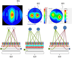
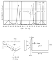
도 8은 다양한 디스플레이 구조에서의 각도 빛 분포에 대한 코노스코프 설명도이다.8 is a conoscopic illustration of angular light distribution in various display structures.
도 8에 도시된 바와 같이, 좌측 도면(801)은 3D 자동 스테레오스코픽 디스플레이(810)의 자동 스테레오스코픽 코노스코프(Autostreoscopic Conoscope) 이미지를 나타내고, 중앙 도면(802)은 상부 및 하부의 프리즘 구조를 가지는 2 피크 디스플레이(820)의 2 피크 코노스코프(Twin Peak Conoscope) 이미지를 나타내고, 우측 도면(803)은 듀얼 뷰 디스플레이(830)의 코노스코프 이미지를 나타낸다.8, the
구체적으로 살펴보면, 좌측 도면(801)은 3D 자동 스테레오스코픽 디스플레이(810)의 전형적인 빛 분포이고 3D 자동 스테레오스코픽 디스플레이(810)의 단면도가 나타나 있다. Specifically, the left-
중앙 도면(802)은 2 피크 디스플레이(820)의 경우로 상부 및 하부에 각기 다른 프리즘이 사용된다.The central diagram 802 is a two-
우측 도면(803)은 듀얼 뷰잉 필름(830)의 경우로서, 90도의 프리즘 각도 및 50um의 프리즘 피치와, 30um의 렌즈 피치를 가지는 구조에서 측정된 코노스코프 이미지를 나타낸다. 여기서, 측정된 코노스코프 이미지는 픽셀 모아레(![]()
![]()
도 9는 본 발명의 실시 예에 따른 듀얼 뷰잉 필름이 적용된 듀얼 뷰 디스플레이에서의 좌우측 시야에 대한 예시도이다.FIG. 9 is an exemplary view of right and left views in a dual view display to which a dual viewing film according to an embodiment of the present invention is applied.
도 9에 도시된 바와 같이, 본 발명의 실시 예에 따른 듀얼 뷰 디스플레이는 좌우 측면 발광 LED(511 및 512), 반사면(520), 패턴을 가진 도광판(530), 듀얼 뷰잉 필름(540) 및 디스플레이 패널(550)을 포함한다. 듀얼 뷰잉 필름(540)은 상부에 높은 정밀도를 가지는 미세 복사를 이용한 렌즈 출력층과 하부에 프리즘 입력층을 포함한다. 도광판(530)은 양측의 구조화된 도광판 패턴을 가진다. 이미지 아래의 상부 측은 수평 방향으로 정렬된 렌즈 패턴을 가지는 반면, 하부 측은 렌즈 패턴에 수직인 얕은 프리즘 패턴을 가진다.9, a dual view display according to an embodiment of the present invention includes left and right
듀얼 뷰 디스플레이는 높은 재생률을 가진 디스플레이 패널(550)을 이용함으로써, 시차 장벽 디스플레이에서 발생하는 해상도 감소 문제와 좌측뷰(901) 및 우측뷰(902)에 대한 시야 반전을 향상시킬 수 있다.By using the
듀얼 뷰 디스플레이는 좌측뷰(901)와 우측뷰(902)에 나타난 바와 같이, 이미지의 해상도를 감소시키지 않는 시간적 멀티플렉싱(Temporal Multiplexing)을 이용한다. 듀얼 뷰 디스플레이는 풀 해상도(Full Resolution) 이미지를 유지하도록, 다른 이미지를 연속적으로 디스플레이한다. 일반적인 LCD 디스플레이 패널과의 차이점은 높은 재생률(예컨대, 60Hz 이상)의 디스플레이 패널(550), 좌우 측면 발광 LED(511 및 512) 및 듀얼 뷰잉 필름(540)을 이용하는 것이다.The dual view display utilizes temporal multiplexing, which does not reduce the resolution of the image, as shown in left view 901 and right view 902. The dual view display continuously displays other images to maintain a full resolution image. The difference from the conventional LCD display panel is that the
도 10 및 도 11은 본 발명의 실시 예에 따른 시간적 멀티플렉싱의 듀얼 뷰 디스플레이를 통해 좌측, 중앙 및 우측 시청자가 바라보는 이미지에 대한 설명도와 이미지에 대한 예시도이다.FIGS. 10 and 11 are illustrations of images viewed by left, center and right viewers through a dual view display of temporal multiplexing according to an embodiment of the present invention.
도 10에 도시된 바와 같이, 시간적 멀티플렉싱의 듀얼 뷰 디스플레이는 하나의 뷰잉 존(Single Viewing Zone)을 제공한다. 시간적 멀티플렉싱의 듀얼 뷰 디스플레이는 우측 사용자(1001) 및 좌측 사용자(1002)에게 이미지의 해상도가 감소되지 않은 우(R) 이미지와 좌(L) 이미지를 각각 제공한다. 즉, 원본 이미지의 해상도 및 시야 반전에 영향을 미치지 않는다. 단, 중앙 사용자(1003)는 우(R) 및 좌(L) 이미지가 혼합된 이미지를 보게 된다.As shown in FIG. 10, the dual view display of temporal multiplexing provides a single viewing zone. The dual view display of temporal multiplexing provides the
도 11에 도시된 바와 같이, 시간적 멀티플렉싱의 듀얼 뷰 디스플레이(500)는 프리즘 각도 및 프리즘 피치가 90도 및 50um이고 상부에 렌즈를 가진 듀얼 뷰잉 필름을 이용하여 서로 다른 이미지를 디스플레이한다.As shown in FIG. 11, the
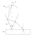
도 12 및 도 13은 본 발명의 실시 예에 따른 프리즘 꼭지각 및 입력 각도에 의한 출력 각도 시뮬레이션과 출력 각도 계산 과정에 대한 설명도이다.12 and 13 are explanatory diagrams of an output angle simulation and an output angle calculation process according to a prism apex angle and an input angle according to an embodiment of the present invention.
듀얼 뷰잉 필름은 빛의 분포를 대칭적으로 축 이동시키기 위해, 프리즘 꼭지각은 80도 이상이 된다.In order to symmetrically move the distribution of light symmetrically, the dual viewing film has a prism apex angle of 80 degrees or more.
도 12에 도시된 바와 같이, 프리즘 하프 각도가 10도 내지 55도의 범위를 가지고, 입력 각도가 50도 내지 80의 범위를 가지는 경우, 듀얼 뷰잉 필름의 출력 각도가 시뮬레이션되어 나타나 있다.As shown in Fig. 12, when the prism half angle is in the range of 10 to 55 degrees and the input angle is in the range of 50 to 80, the output angle of the dual viewing film is simulated.
이러한 시뮬레이션에 기초하여, 도 13에 도시된 도광판(520)에서부터 입사된 빛이 프리즘 입력층(720)과 렌즈 출력층(730)을 통해 출력되는 출력 각도가 나타나 있다.An output angle at which light incident from the
듀얼 뷰잉 필름의 특정 오프 축의 출력 각도(![]()
![]()
![]()
![]()

여기서, ![]()
![]()
![]()
![]()
![]()
![]()
![]()
![]()
![]()
![]()
![]()
![]()
![]()
![]()
상기 [수학식 1]에 따르면, 프리즘 입력층(720)의 꼭지점 하프 각도(![]()
![]()
![]()
![]()
![]()
![]()
![]()
![]()
![]()
![]()
![]()
![]()
예를 들어, 시청자 위치가 주축(on-axis)으로부터 40도에 있다면, 듀얼 뷰 디스플레이에 대한 빛의 입력 각도는 70도가 된다. 그리고 프리즘 하프 각도는 43가 될 것이다. 이러한 듀얼 뷰잉 필름의 출력 각도에 기초하여 빛이 시청자를 향하도록 듀얼 뷰 디스플레이가 구현될 수 있다.For example, if the viewer position is at 40 degrees from the on-axis, the light input angle to the dual view display is 70 degrees. And the prism half angle would be 43. A dual view display can be implemented such that the light is directed to the viewer based on the output angle of the dual viewing film.
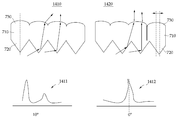
도 14는 본 발명의 실시 예에 따른 프리즘 입력층 및 렌즈 출력층 간의 피크 편차에 따른 크로스토크에 대한 설명도이다.14 is an explanatory diagram of crosstalk according to a peak deviation between a prism input layer and a lens output layer according to an embodiment of the present invention.
좌측 듀얼 뷰잉 필름(1410)은 프리즘 입력층(720) 및 렌즈 출력층(730) 간의 피크가 어긋나지 않아 피크 편차가 없고 정확하게 피크 정렬이 맞은 경우이다. 이러한 좌측 듀얼 뷰잉 필름(1410)의 빛의 분포를 살펴보면, 크로스토크에서 다른 입력 각도(예컨대, 10°)를 가진다.The left
크로스토크는 좌측 및 우측 이미지 채널들의 불완전한 분리를 나타내며 이미지가 중첩되어 보이는 현상을 의미한다. 그래서 하나는 이중 노출과 같이 다른 곳으로 누출되거나 번진다. 그리고 본 발명에서의 크로스토크는 좌측 또는 우측의 최대 밝기 강도를 갖는 시야 각도에서 좌측 광원 및 우측 광원 사이의 밝기 강도의 비율을 나타낸다. 좌측 LED의 최대 밝기 강도 및 그 위치가 각각 1 및 30도일 때, 30도에서 우측 LED의 밝기 강도는 0.1이다. 그러면, 크로스토크는 10%(0.1/1)이다. Crosstalk refers to an imperfect separation of the left and right image channels and the appearance of overlapping images. So one can leak or spread to other places like double exposures. The crosstalk in the present invention represents the ratio of the brightness intensity between the left light source and the right light source at a viewing angle having the maximum brightness intensity on the left or right side. When the maximum brightness intensity of the left LED and its position are 1 and 30 degrees, respectively, the brightness intensity of the right LED is 0.1 at 30 degrees. Then, the crosstalk is 10% (0.1 / 1).
크로스토크가 적을수록, 적게 번질수록, 시청자에게 더욱 편안한 시야가 제공될 수 있다. 3D에서 많이 다른 크로스토크 레벨이 존재하고, 크로스토크의 레벨은 시청자의 양쪽 눈 사이의 거리 및 주관적인 느낌에 상당히 의존되기 때문에, 더 좋은 크로스토크 레벨을 결정하는 것은 쉽지 않다. 본 발명에 따른 크로스토크 레벨은 0.47% 내지 1%가 될 수 있다. 0.47% 내지 1%의 크로스토크 레벨은 자동 스테레오스코픽 3D에서 5%의 크로스토크에 비하면 매우 적은 크로스토크 레벨이라는 것을 알 수 있다.The smaller the crosstalk is and the less the crosstalk is, the more comfortable the field of view can be provided to the viewer. It is not easy to determine a better crosstalk level because there are many different crosstalk levels in 3D and the level of crosstalk is highly dependent on the distance between the eyes of the viewer and the subjective feel. The crosstalk level according to the present invention can be 0.47% to 1%. It can be seen that the crosstalk levels of 0.47% to 1% are very low crosstalk levels compared to 5% crosstalk in auto stereoscopic 3D.
좌측 및 우측 듀얼 뷰얼 필름(1410 및 1420)은 프리즘 피크와 렌즈 피크 사이의 미정렬의 일례를 설명한다. 좌측 듀얼 뷰잉 필름(1410)은 프리즘 피크와 렌즈 피크 사이의 어긋나지 않는다. 좌측 듀얼 뷰잉 필름(1410)의 크로스토크는 하기의 [표 1]의 모델링 결과에 따르면 7.75%이다. 우측 듀얼 뷰잉 필름(1420)은 5um 어긋나 있다. 우측 듀얼 뷰잉 필름(1420)의 크로스토크 레벨은 하기의 [표 1]의 모델링 결과에 따르면 0.94%로 줄어든다.The left and right dual-
우측 듀얼 뷰잉 필름(1420)은 프리즘 입력층(720) 및 렌즈 출력층(730) 간의 피크 중심이 어긋나서 피크 편차가 있는 경우이다. 이러한 우측 듀얼 뷰잉 필름(1420)의 빛을 분포를 살펴보면, 어긋남은 프리즘 입력층(720) 및 렌즈 출력층(730)간에 어떤 오버랩을 주지 않아 크로스토크가 감소되는 것을 알 수 있다.The right
즉, 우측 듀얼 뷰잉 필름(1420)의 일례에서 살펴본 바와 같이, 듀얼 뷰 디스플레이의 크로스토크가 기설정된 값 이하로 감소되도록, 프리즘 입력층(720)의 프리즘 피치(PP)와 렌즈 출력층(730)의 렌즈 피치(Pl)의 피크 중심이 서로 어긋나는 것을 특징으로 한다. 예를 들어, 프리즘 입력층(720)의 프리즘 피치(PP)와 렌즈 출력층(730)의 렌즈 피치(Pl) 간의 피크 편차(X)는 하기의 [수학식 2]와 같이 나타난다.That is, as shown in the example of the right
![]()
![]()
여기서, Pl은 렌즈 피치, PP는 프리즘 피치, X는 피크 편차를 나타낸다.Here, P l is the lens pitch, P P is Prism pitch, and X represents a peak deviation.
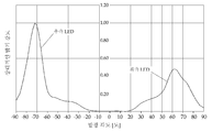
도 15는 본 발명의 실시 예에 따른 프리즘 입력층 및 렌즈 출력층 간의 피크 편차에 따른 시야각 분포 시뮬레이션에 대한 설명도이다.15 is an explanatory diagram of simulation of a viewing angle distribution according to a peak deviation between a prism input layer and a lens output layer according to an embodiment of the present invention.
프리즘 입력층(720) 및 렌즈 출력층(730) 간의 피크 편차에 따른 시야각 분포 시뮬레이션 결과 그래프가 도 15에 나타나 있고, 시뮬레이션 결과표는 하기의 [표 1]과 같이 나타난다. 크로스토크 시뮬레이션을 위한 프리즘 각도는 고정되어 있고 피크가 어긋난 값은 0um 내지 22um까지 변화한다.A graph of the simulation result of the viewing angle distribution according to the peak deviation between the
상기 [표 1]의 크로스토크 시뮬레이션 결과에 따르면, 피크 차이가 0um의 경우는 7.75% 크로스토크를 가지는 32.4도의 피크 각도를 보인다. 피크 차이가 4um의 경우는 1.56% 크로스토크를 가지는 28.04 피크 각도를 보인다. 0um 내지 22um 범위까지의 경우들을 비교하면, 프리즘 입력층(720) 및 렌즈 출력층(730) 간의 피크-투-피크 어긋남은 크로스토크 감소를 현저하게 향상시킨다. 이는 시스템 성능을 향상시키고, 최대 밝기를 증폭하기 위함이다.According to the crosstalk simulation results in Table 1, when the peak difference is 0um, the peak angle is 32.4 degrees with 7.75% crosstalk. And a peak angle of 28.04 with a 1.56% crosstalk when the peak difference is 4 μm. Comparing the cases from 0um to 22um, the peak-to-peak shift between the
상기 시뮬레이션 결과를 살펴보면, 본 발명의 실시 예에 따른 듀얼 뷰잉 필름은 최소 크로스토크(5% 이하)를 유지하고 최고의 주축(On axis) 밝기를 가질 수 있다. 듀얼 뷰잉 필름은 프리즘 입력층의 프리즘 피치와 렌즈 출력층의 렌즈 피치 간의 피크-투-피크 피치 값이 0um 내지 20um 범위로 어긋날 때 시야각이 최소 14.4도 이상이 된다. 여기서, 더 바람직하게는 프리즘 꼭지각이 85도 내지 90도의 범위로 변화하고, 피크-투-피크 어긋남이 0um 내지 7um 범위의 구조로 구현되는 것이 바람직하다.According to the simulation results, the dual viewing film according to the embodiment of the present invention can maintain the minimum crosstalk (5% or less) and have the best on axis brightness. The dual viewing film has a viewing angle of at least 14.4 degrees when the peak-to-peak pitch value between the prism pitch of the prism input layer and the lens pitch of the lens output layer is shifted in the range of 0 um to 20 um. More preferably, the prism apex angle is changed in the range of 85 degrees to 90 degrees, and the peak-to-peak deviation is in the range of 0 um to 7 um.
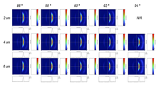
도 16은 본 발명의 실시 예에 따른 프리즘 각도와 피크-투-피크 편차에 따른 광학 시뮬레이션 결과에 대한 설명도이다.16 is an explanatory diagram of optical simulation results according to a prism angle and a peak-to-peak deviation according to an embodiment of the present invention.
서로 다른 피크-투-피크 어긋남과 서로 다른 프리즘 각도를 가지는 조건으로 광학 시뮬레이션 그래프가 도 16에 도시되어 있고, 광학 시뮬레이션 결과표는 하기의 [표 2]에 나타나 있다.The optical simulation graph is shown in Fig. 16 with different peak-to-peak deviations and different prism angles, and the optical simulation result table is shown in Table 2 below.
상기 [표 2]에 따르면, 크로스토크가 작으면서 상대적인 밝기가 높은 범위는 프리즘 각도가 86도이고 피크 편차가 4um 및 6um인 경우, 프리즘 각도가 88도이고 피크 편차가 4um 및 6um인 경우 및 프리즘 각도가 90도이고 피크 편차가 6um인 경우이다.According to Table 2, in the range where the crosstalk is small and the relative brightness is high, the prism angle is 86 degrees, the peak deviations are 4 um and 6 um, the prism angle is 88 degrees, the peak deviations are 4 um and 6 um, The angle is 90 degrees and the peak deviation is 6 um.
상기 [표 2]에 따르면, 4um 내지 6um의 피크-투-피크 편차에 86, 88 및 90의 프리즘 각도를 가지는 경우가 가장 적은 크로스토크와 최대 밝기를 가질 수 있다. 크로스토크가 최저인 경우는 6um의 피크-투-피크 편차에 프리즘 각도가 88도일 때이다. 그리고 최고의 밝기인 경우는 6um의 피크-투-피크 편차를 가지고 프리즘 각도가 86도일 때와 6um의 피크-투-피크 편차를 가지고 프리즘 각도 88도일 때이다.According to the above Table 2, the prismatic angle of 86, 88 and 90 with the peak-to-peak deviation of 4 um to 6 um can have the lowest crosstalk and maximum brightness. When the crosstalk is the lowest, it is the peak-to-peak deviation of 6 um and the prism angle is 88 degrees. The highest brightness is when the prism angle is 86 degrees with a peak-to-peak deviation of 6 um and the prism angle is 88 degrees with a peak-to-peak deviation of 6 um.
도 17은 본 발명의 듀얼 뷰잉 필름에서 발생하는 1차 및 2차 크로스토크에 대한 설명도이다.17 is an explanatory diagram of primary and secondary crosstalk generated in the dual viewing film of the present invention.
피크-투-피크 편차가 5um로 고정된 분석 결과가 하기의 [표 3]에 나타나 있으며, 1차 및 2차 크로스토크에 대한 그래프가 도 17에 도시되어 있다.The analysis results in which the peak-to-peak deviation is fixed at 5 mu m are shown in [Table 3] below, and a graph for the primary and secondary crosstalk is shown in Fig.
상기 [표 3]에 따르면, 5개의 다른 프리즘 각도 중에서 88도의 프리즘 각도일 때가 크로스토크가 낮으면서 밝기가 높게 된다.According to Table 3, when the prism angle is 88 degrees among five different prism angles, the crosstalk is low and the brightness is high.
듀얼 뷰잉 디스플레이의 시청자가 두 명이기 때문에, 양쪽 위치에서 크로스토크 레벨이 고려되어야 한다. 그리고 시청자가 디스플레이를 볼 때, 크로스토크 레벨이 고려되어야 한다.Since the dual view display has two viewers, the crosstalk level should be considered at both locations. When the viewer views the display, the crosstalk level must be considered.
도 17에 도시된 바와 같이, 1차 크로스토크는 최대 밝기 시야각에서 다른 쪽 LED로부터의 밝기 값으로 한쪽 LED로부터의 밝기 최대값을 나눈 비율로 나타난다. 1차 크로스토크는 낮은 레벨로 나타난다. 반면, 반대쪽 도광판으로부터 후면 반사된 LED 빛은 2차 크로스토크를 발생시킨다.As shown in Fig. 17, the primary crosstalk is represented by the ratio of brightness from the other LED at the maximum brightness viewing angle divided by the maximum brightness from one LED. The primary crosstalk appears at a low level. On the other hand, the back-reflected LED light from the opposite light guide plate generates a second crosstalk.
후면 반사로부터 본질적으로 야기된 이러한 2차 크로스토크는 반사된 도광판(1700)의 에지 표면의 패턴 처리(1710)에 의해 최소화될 수 있다. 도광판(1700)의 반사된 에지 표면을 최소화하기 위한 패턴 처리(1710)는 도 17에 도시된 바와 같이 가로 1um 내지 2um 피치 및 1um 내지 2um 깊이 패턴이 된다.This secondary crosstalk, which is essentially caused by back reflection, can be minimized by the
2차 크로스토크 레벨은 상대적으로 후면 반사 때문에 높기 때문에, 도광판 수정과 블랙 마스킹과 같은 에지 표면 처리가 된 듀얼 뷰잉 필름에 의해 최소화될 수 있다.Secondary crosstalk levels are relatively high due to back reflection, and can be minimized by dual viewing films with edge surface treatments such as light guide plate modification and black masking.
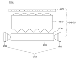
도 19은 본 발명의 실시 예에 따른 듀얼 뷰잉 필름을 이용한 듀얼 뷰 디스플레이 장치의 구성도이다.19 is a configuration diagram of a dual view display device using a dual viewing film according to an embodiment of the present invention.
도 19에 도시된 바와 같이, 본 발명의 실시 예에 따른 듀얼 뷰 디스플레이 장치(1800)는 좌측 및 우측 LED 광원(1811 및 1812)으로 이루어진 좌측 및 우측 광원(1810), 반사면(1820), 도광판(1830), 듀얼 뷰잉 필름(1840) 및 디스플레이 패널(1850)을 포함한다.19, a dual
좌측 및 우측 광원(1810)은 연속적인 좌측 및 우측 타이밍에 따라 좌측 또는 우측으로 빛을 출력한다. 좌측 및 우측 광원(1810)은 좌측 LED 광원(1811) 및 우측 LED 광원(1812)으로 이루어진다. 여기서, 좌측 및 우측 LED 광원(1811 및 1812)은 듀얼 뷰 디스플레이 장치(1800)의 양쪽 측면에서 동일한 밝기 강도를 가지거나 서로 다른 밝기 강도를 가질 수 있다.The left and right
반사면(1820)은 좌측 및 우측 광원(1810)에서 출력된 빛을 후면 반사시킨다.The reflecting
도광판(1830)은 좌측 및 우측 광원(1810)에서 출력된 빛의 경로를 가이드한다.The
듀얼 뷰잉 필름(1840)은 하부에 복수의 프리즘이 연속적으로 형성되는 프리즘 입력층과 상부에 복수의 렌즈가 연속적으로 형성되는 렌즈 출력층을 포함한다. 듀얼 뷰잉 필름(1840)은 도광판(1830)으로부터 프리즘 입력층의 좌측 또는 우측으로 입력된 빛을 반사시키고, 그 반사된 빛을 렌즈 출력층을 통해 듀얼 뷰 디스플레이의 법선 축에서 벗어난 좌측 또는 우측 방향의 시청자를 향하도록 굴절시킨다. 여기서, 프리즘 입력층은 듀얼 뷰잉 필름(1840)의 하부에 좌측 및 우측 광원(1810)의 발광 방향과 수직인 패턴을 가진다. 그리고 렌즈 출력층은 듀얼 뷰잉 필름(1840)의 상부에 좌측 및 우측 광원(1810)의 발광 방향과 평행한 패턴을 가진다.The
디스플레이 패널(1850)은 듀얼 뷰잉 필름(1840)에서 굴절된 빛을 이용하여 좌측 또는 우측 방향의 시청자에게 서로 다른 이미지를 표시한다. 디스플레이 패널(1850)은 일반적인 LCD 디스플레이 패널보다 높은 재생률을 가진다. 즉, 디스플레이 패널(1850)은 좌측 또는 우측 방향의 시청자에게 서로 다른 이미지를 미리 설정된 재생률 이상으로 재생시켜 액정 디스플레이를 통해 표시할 수 있다.The
한편, 동일한 밝기 강도를 가지는 좌측 및 우측 LED 광원(1811 및 1812)에서 듀얼 뷰잉 필름(1840)은 필름에서 상부 렌즈의 패턴과 하부 프리즘 패턴 사이의 피치 편차로 인해 비대칭적인 빛의 출력 분포를 가진다. 이는 크로스토크 감소를 위함이다.On the other hand, in the left and right
하지만, 좌측 및 우측에서 서로 다른 강도를 가지는 좌측 및 우측 LED 광원(1811 및 1812)을 가지는 듀얼 뷰 디스플레이 장치(1800)는 비대칭적인 빛의 출력 분포가 아닌 대칭적인 빛의 출력 분포를 가질 수 있다.However, the dual
도 19는 본 발명에 적용된 양쪽 측면 LED들을 가진 도광판을 이용한 빛 출력 분포의 광학 시뮬레이션 결과에 대한 설명도이다.FIG. 19 is an explanatory diagram of optical simulation results of a light output distribution using a light guide plate having both side LEDs applied to the present invention. FIG.
오른쪽 빛 출력 분포 곡선(1902)은 듀얼 뷰 디스플레이 장치(1800)에서 좌측 LED 광원(1811)을 이용한 단일 측면 입력에 대한 빛 출력을 보여준다. 반면, 왼쪽 빛 출력 분포 곡선(1901)은 듀얼 뷰 디스플레이 장치(1800)에서 우측 LED 광원(1812)을 이용한 단일 측면 입력에 대한 빛 출력을 보여준다. 즉, 도 19의 결과에 따르면, 좌측 및 우측 광원(1810)을 가진 도광판(1820)의 빛 출력은 대칭적으로 분포한다.The right light output
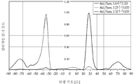
도 20 및 도 21은 본 발명의 실시 예에 따른 두 가지 종류의 듀얼 뷰잉 필름을 이용한 광학 시뮬레이션 결과에 대한 설명도이다.20 and 21 are explanatory diagrams of optical simulation results using two kinds of dual viewing films according to an embodiment of the present invention.
도 20에는 86도의 프리즘 각도와 5um의 피치 편차를 가지는 듀얼 뷰잉 필름의 광학 시뮬레이션 결과가 나타나 있다. 또한, 도 21에는 88도의 프리즘 각도와 5um의 피치 편차를 가지는 듀얼 뷰잉 필름의 광학 시뮬레이션 결과가 나타나 있다. 도 20 및 도 21에 도시된 바와 같이, 듀얼 뷰잉 필름은 광학 시뮬레이션 결과에서 듀얼 뷰잉 필름의 상부 및 하부의 피치 편차 때문에 비대칭적 빛 분포를 가진다. 두 가지(86도/5um, 88도/5um) 종류의 듀얼 뷰잉 필름을 이용한 광학 시뮬레이션 결과에서 우측 LED 광원(1812)에 의한 빛 출력은 좌측 LED 광원(1811)보다 30% 이하를 가진다.20 shows the optical simulation results of a dual viewing film having a prism angle of 86 degrees and a pitch deviation of 5 um. 21 shows an optical simulation result of a dual viewing film having a prism angle of 88 degrees and a pitch deviation of 5 um. As shown in Figs. 20 and 21, the dual viewing film has an asymmetric light distribution due to the pitch deviation at the top and bottom of the dual viewing film in the optical simulation results. In the optical simulation results using the dual viewing films of the two types (86 degrees / 5 um, 88 degrees / 5 um), the light output by the right
이와 같은 결과에 따라, 듀얼 뷰잉 필름에서 비대칭적 빛 입력이 필요하다. 듀얼 뷰잉 필름의 프리즘 입력층 및 렌즈 출력층 간의 피치 편차가 있는 경우, 좌측 및 우측 LED 광원(1811 및 1812)은 비대칭적인 빛의 분포를 가지도록 서로 다른 밝기 강도의 빛을 좌측 및 우측으로 각각 출력한다. 예를 들어, 우측 LED 광원(1812)의 밝기 강도는 좌측 LED 광원(1811) 보다 최소 20% 이상으로 설정될 수 있다. 여기서, 우측 LED 광원(1812)의 발광 각도는 좌측 LED 광원(1811)과 동일하게 한다.As a result, asymmetrical light input is required in the dual viewing film. When there is a pitch deviation between the prism input layer and the lens output layer of the dual viewing film, the left and right
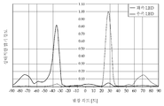
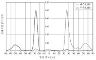
도 22 및 도 23은 본 발명의 실시 예에 따른 서로 다른 밝기 강도를 가지는 광원을 이용한 듀얼 뷰 디스플레이 장치의 빛 출력 분포에 대한 설명도이다.22 and 23 are explanatory diagrams of a light output distribution of a dual view display device using light sources having different brightness intensities according to an embodiment of the present invention.
도 22 및 도 23에 도시된 그래프는 86도의 프리즘 각도와 5um의 피치 편차를 가지는 듀얼 뷰잉 필름을 이용한 듀얼 뷰 디스플레이 장치에 대한 것이다.The graphs shown in FIGS. 22 and 23 are for a dual view display device using a dual viewing film having a prism angle of 86 degrees and a pitch deviation of 5 um.
도 22에는 1.0의 밝기 강도를 가지는 좌측 LED 광원, 1.23의 밝기 강도를 가지는 우측 LED 광원, 1.32의 밝기 강도를 가지는 우측 LED 광원에 대한 빛 출력 분포가 나타나 있다. 구체적으로 살펴보면, 1.23의 밝기 강도를 가지는 우측 LED 광원에 대한 빛 출력 분포는 1.0의 밝기 강도를 가지는 좌측 LED 광원에 빛 출력 분포에 비해서 비대칭적인 출력 분포를 가진다. 반면, 1.32의 밝기 강도를 가지는 우측 LED 광원에 대한 빛 출력 분포는 1.23의 밝기 강도의 광원에 비해 대칭적인 빛 출력 분포를 가진다.FIG. 22 shows the light output distribution for a left LED light source having a brightness intensity of 1.0, a right LED light source having a brightness intensity of 1.23, and a right LED light source having a brightness intensity of 1.32. Specifically, the light output distribution for the right LED light source having a brightness intensity of 1.23 has an asymmetrical output distribution as compared with the light output distribution for the left LED light source having a brightness intensity of 1.0. On the other hand, the light output distribution for a right LED light source having a brightness intensity of 1.32 has a symmetrical light output distribution as compared with a light source having a brightness intensity of 1.23.
도 23에는 1.0의 밝기 강도를 가지는 좌측 LED 광원과 1.23의 밝기 강도를 가지는 우측 LED 광원에 대하 빛의 출력은 대칭적인 분포를 가진다. 결론적으로, 듀얼 뷰 디스플레이 장치는 대칭적인 빛의 출력 분포를 위해, 좌측 또는 우측의 방향적 분포를 고려하여, 백라이트의 양쪽 측면에서 서로 다른 강도를 가지는 광원을 가진다. 이는 듀얼 뷰잉 필름의 피치 편차에 의한 비대칭적인 빛의 출력이 대칭적으로 변경하기 위함이다.FIG. 23 shows a symmetrical distribution of light output for a left LED light source having a brightness intensity of 1.0 and a right LED light source having a brightness intensity of 1.23. Consequently, the dual view display device has light sources having different intensities on both sides of the backlight, taking into account the left or right directional distribution, for symmetrical light output distribution. This is for symmetrically changing the asymmetrical light output due to the pitch deviation of the dual viewing film.
도 24는 본 발명의 실시 예에 따른 듀얼 도광판을 이용한 듀얼 뷰 디스플레이 장치의 구성도이다.24 is a configuration diagram of a dual view display device using a dual light guide plate according to an embodiment of the present invention.
도 24에 도시된 바와 같이, 본 발명의 실시 예에 따른 듀얼 도광판을 이용한 듀얼 뷰 디스플레이 장치(1800)는 좌측 및 우측 LED 광원(1811 및 1812)으로 이루어진 좌측 및 우측 광원(1810), 반사면(1820), 제1 및 제2 도광판(1831 및 1832)으로 이루어진 듀얼 도광판, 듀얼 뷰잉 필름(1840) 및 디스플레이 패널(1850)을 포함한다.24, a dual
피크 편차를 가지는 듀얼 뷰잉 필름에서는 비대칭적인 밝기 강도를 가지는 좌측 및 우측 LED 광원(1811 및 1812)에 의한 빛 입력이 필요하다. 만약 좌측 및 우측 LED 광원(1811 및 1812)의 밝기 강도가 수정되지 않는다면, 제1 및 제2 도광판(1831 및 1832)은 동일한 밝기 강도를 가지는 좌측 및 우측 LED 광원(1811 및 1812)을 구비한 듀얼 뷰 디스플레이 장치(1800)에서도 대칭적인 빛의 출력 분포를 가지게 한다.In a dual viewing film having a peak deviation, light input by the left and right
구체적으로 살펴보면, 듀얼 도광판은 수평 방향으로 위치한 제1 및 제2 도광판(1831 및 1832)으로 이루어지고, 제1 및 제2 도광판(1831 및 1832)이 좌측 및 우측 LED 광원(1811 및 1812)과 각각 결합된다. 우측 LED 광원(1812)은 제1 도광판(1831)과 결합되고, 좌측 LED 광원(1811)은 제2 도광판(1832)과 결합된다. 듀얼 도광판은 제1 및 제2 도광판(1831 및 1832)은 좌측 및 우측 광원으로부터 출력된 빛의 경로를 각각 결합된 제1 및 제2 도광판(1831 및 1832)을 통해 각각 가이드한다. 또한, 제1 도광판(1831) 및 제2 도광판(1832)이 각각 듀얼 도광판의 상부 및 하부에 위치한 경우, 제2 도광판(1832)의 상부 표면과 제1 도광판(1831)의 하부 표면 사이에 에어 갭(Air Gap)이 형성될 수 있다. 제1 및 제2 도광판(1831 및 1832)은 하나의 도광판과 같이 상부 및 하부 표면상에서 동일한 연속적인 렌즈 패턴 및 프리즘 패턴을 가진다.Specifically, the dual light guide plate includes first and second
도 25는 본 발명의 실시 예에 따른 동일한 광원과 결합된 듀얼 도광판에 대한 비대칭적인 광학 시뮬레이션 결과에 대한 설명도이다.25 is an explanatory diagram of asymmetric optical simulation results for a dual light guide plate combined with the same light source according to an embodiment of the present invention.
도 25에 도시된 바와 같이, 동일한 좌측 및 우측 LED 광원(1811 및 1812)에 의한 듀얼 도광판은 비대칭적인 빛 출력 분포를 가진다. 우측 LED 광원(1812)과 결합된 제1 도광판(1831)의 빛 출력 분포가 좌측 LED 광원(1811)과 결합된 제2 도광판(1832)의 빛 출력 분포에 비해 낮은 분포를 가진다.As shown in Fig. 25, the dual light guide plate by the same left and right
도 26은 본 발명의 실시 예에 따른 듀얼 도광판을 이용한 듀얼 뷰 디스플레이 장치에 대한 광학 시뮬레이션 결과에 대한 설명도이다.26 is an explanatory diagram of optical simulation results for a dual view display device using a dual light guide plate according to an embodiment of the present invention.
도 26에 도시된 바와 같이, 비대칭적인 빛의 출력 분포를 가지는 듀얼 도광판을 이용한 듀얼 뷰 디스플레이 장치(1800)는 대칭적인 빛의 출력 분포를 가진다. 좌측 및 우측 LED 광원(1811 및 1812)의 밝기 강도 수정이 가능하지 않은 경우, 듀얼 도광판을 이용한 듀얼 뷰 디스플레이 장치(1800)가 적용될 수 있다.As shown in FIG. 26, the dual
이상의 설명은 본 발명을 예시적으로 설명한 것에 불과하며, 본 발명이 속하는 기술 분야에서 통상의 지식을 가진 자에 의해 본 발명의 기술적 사상에서 벗어나지 않는 범위에서 다양한 변형이 가능할 것이다. 따라서 본 발명의 명세서에 개시된 실시 예들은 본 발명을 한정하는 것이 아니다. 본 발명의 범위는 아래의 특허청구범위에 의해 해석되어야 하며, 그와 균등한 범위 내에 있는 모든 기술도 본 발명의 범위에 포함되는 것으로 해석해야 할 것이다.The foregoing description is merely illustrative of the present invention, and various modifications may be made by those skilled in the art without departing from the spirit of the present invention. Accordingly, the embodiments disclosed in the specification of the present invention are not intended to limit the present invention. The scope of the present invention should be construed according to the following claims, and all the techniques within the scope of equivalents should be construed as being included in the scope of the present invention.
511, 1811: 좌측 LED 광원
512, 1812: 우측 LED 광원
520, 1820: 반사면
530, 1830: 도광판
1831: 제1 도광판
1832: 제2 도광판
540, 1840: 듀얼 뷰잉 필름
550, 1850: 디스플레이 패널
710: 기판층
720: 프리즘 입력층
730: 렌즈 입력층511, 1811: Left LED
520, 1820: Reflecting
1831: first light guide plate 1832: second light guide plate
540, 1840:
710: substrate layer 720: prism input layer
730: Lens input layer
Claims (16)
기판층;
상기 기판층 하부에 프리즘 꼭지각 및 프리즘 피치를 가지는 복수의 프리즘이 형성되는 프리즘 입력층; 및
상기 기판층 상부에 렌즈 피치와 렌즈 곡률 반경을 가지는 복수의 렌즈가 형성되는 렌즈 출력층을 포함하고,
상기 프리즘 입력층의 좌측 또는 우측으로 입력된 빛이 반사되고, 상기 반사된 빛이 상기 렌즈 출력층을 통해 상기 듀얼 뷰 디스플레이의 법선 축에서 벗어난 좌측 또는 우측 방향의 시청자를 향하도록 굴절되는 것을 특징으로 하는 듀얼 뷰잉 필름.For a dual viewing film in a dual view display,
A substrate layer;
A prism input layer in which a plurality of prisms having a prism apex angle and a prism pitch are formed under the substrate layer; And
And a lens output layer on which a plurality of lenses having a lens pitch and a lens radius of curvature are formed on the substrate layer,
The light input to the left or right of the prism input layer is reflected and the reflected light is refracted through the lens output layer so as to face the viewer in the left or right direction away from the normal axis of the dual view display. Dual viewing film.
상기 렌즈 출력층에서 굴절된 빛이 상기 듀얼 뷰 디스플레이의 법선 축에서 ±10도 이상 벗어난 좌측 또는 우측 방향의 시청자를 향하는 것을 특징으로 하는 듀얼 뷰잉 필름.The method according to claim 1,
Wherein the refracted light from the lens output layer is directed to a viewer in the left or right direction deviating by more than +/- 10 degrees from the normal axis of the dual view display.
상기 프리즘 입력층은,
80도 내지 90도 사이의 프리즘 꼭지각과 40um 내지 60um 사이의 프리즘 피치를 가지는 복수의 프리즘이 형성되는 것을 특징으로 하는 듀얼 뷰잉 필름.The method according to claim 1,
The prism-
Wherein a plurality of prisms having a prism apex angle between 80 and 90 degrees and a prism pitch between 40 and 60 um are formed.
상기 듀얼 뷰 디스플레이의 크로스토크가 기설정된 값 이하로 감소되도록, 상기 프리즘 입력층의 프리즘 피치와 상기 렌즈 출력층의 렌즈 피치의 피크 중심이 서로 어긋나있는 것을 특징으로 하는 듀얼 뷰잉 필름.The method according to claim 1,
Wherein a prism pitch of the prism input layer and a peak center of a lens pitch of the lens output layer are shifted from each other such that crosstalk of the dual view display is reduced to a predetermined value or less.
상기 프리즘 입력층의 프리즘 피치와 상기 렌즈 출력층의 렌즈 피치 간의 피크-투-피크 피치 값이 0um 내지 20um 범위로 어긋나는 것을 특징으로 하는 듀얼 뷰잉 필름.5. The method of claim 4,
Peak-to-peak pitch value between the prism pitch of the prism input layer and the lens pitch of the lens output layer is shifted in the range of 0 um to 20 um.
상기 도광판의 양측 에지에 인접하고, 연속적인 좌측 및 우측 타이밍에 따라 좌측 또는 우측으로 빛을 상기 도광판으로 출력하는 좌측 및 우측 광원;
상기 도광판의 하부에 위치하고, 상기 도광판으로부터 출력된 빛을 후면 반사시키는 반사면;
복수의 프리즘이 전체 하부면에 걸쳐 연속적인 프리즘 입력층과 복수의 렌즈가 전체 상부면에 걸쳐 연속적인 렌즈 출력층을 포함하고, 상기 도광판의 상부에 위치하고 상기 도광판으로부터 상기 프리즘 입력층의 좌측 또는 우측으로 입력된 빛을 반사시키고, 상기 반사된 빛을 상기 렌즈 출력층을 통해 듀얼 뷰 디스플레이의 법선 축에서 벗어난 좌측 또는 우측 방향의 시청자를 향하도록 굴절시키는 듀얼 뷰잉 필름; 및
상기 듀얼 뷰잉 필름의 상부에 위치하고, 상기 굴절된 빛을 이용하여 상기 좌측 또는 우측 방향의 시청자에게 서로 다른 이미지를 표시하는 디스플레이 패널을 포함하는 것을 특징으로 하는 듀얼 뷰잉 필름을 이용한 듀얼 뷰 디스플레이 장치.A light guide plate guiding a light path;
Left and right light sources adjacent to both side edges of the light guide plate and outputting light to the light guide plate to left or right according to successive left and right timings;
A reflection surface positioned at a lower portion of the light guide plate and reflecting light output from the light guide plate backward;
A plurality of prisms including a continuous prism input layer and a plurality of lenses extending over the entire lower surface and including a continuous lens output layer over the entire upper surface and disposed on the upper side of the light guide plate and extending from the light guide plate to the left or right side A dual viewing film reflecting the input light and refracting the reflected light through the lens output layer towards a viewer in the left or right direction away from the normal axis of the dual view display; And
And a display panel located above the dual viewing film and displaying different images to the viewer in the left or right direction using the refracted light.
상기 프리즘 입력층은 상기 듀얼 뷰잉 필름의 하부에 상기 좌측 및 우측 광원의 발광 방향과 수직인 패턴을 가지고, 상기 렌즈 출력층은 상기 듀얼 뷰잉 필름의 상부에 상기 좌측 및 우측 광원의 발광 방향과 수직한 패턴을 가지는 것을 특징으로 하는 듀얼 뷰잉 필름을 이용한 듀얼 뷰 디스플레이 장치.The method according to claim 6,
Wherein the prism input layer has a pattern perpendicular to a light emitting direction of the left and right light sources at a lower portion of the dual viewing film, And a display unit for displaying the dual view film.
상기 듀얼 뷰잉 필름의 프리즘 입력층 및 렌즈 출력층 간의 피치 편차가 있고, 상기 좌측 및 우측 광원은 비대칭적인 빛의 분포를 가지도록 서로 다른 밝기 강도의 빛을 좌측 및 우측으로 각각 출력하는 것을 특징으로 하는 듀얼 뷰잉 필름을 이용한 듀얼 뷰 디스플레이 장치.The method according to claim 6,
And the left and right light sources output light having different brightness intensities to the left and right sides, respectively, so that the left and right light sources have a distribution of asymmetrical light, and the prism input layer and the lens output layer of the dual viewing film have a pitch deviation. A dual view display device using a viewing film.
상기 도광판은,
수평 방향으로 위치한 제1 및 제2 도광판으로 이루어지고, 상기 제1 및 제2 도광판이 상기 좌측 및 우측 광원과 각각 결합되고, 상기 좌측 및 우측 광원으로부터 출력된 빛의 경로를 상기 각각 결합된 제1 및 제2 도광판을 통해 각각 가이드하는 것을 특징으로 하는 듀얼 뷰잉 필름을 이용한 듀얼 뷰 디스플레이 장치.The method according to claim 6,
The light-
Wherein the first and second light guide plates are coupled to the left and right light sources, respectively, and the paths of light output from the left and right light sources are connected to the first and second light guide plates, respectively, And the second light guide plate, respectively. The dual view display device according to claim 1,
상기 제1 도광판 및 상기 제2 도광판이 각각 결합된 도광판의 상부 및 하부에 위치하고, 상기 제2 도광판의 상부 표면과 상기 제1 도광판의 하부 표면 사이에 에어 갭이 형성되는 것을 특징으로 하는 듀얼 뷰잉 필름을 이용한 듀얼 뷰 디스플레이 장치.10. The method of claim 9,
Wherein an air gap is formed between the upper surface of the second light guide plate and the lower surface of the first light guide plate, the upper surface of the second light guide plate being coupled to the first light guide plate and the second light guide plate, A dual-view display device using the same.
상기 디스플레이 패널은,
상기 좌측 또는 우측 방향의 시청자에게 서로 다른 이미지를 90Hz 이상의 재생률로 재생시켜 액정 디스플레이를 통해 표시하는 것을 특징으로 하는 듀얼 뷰잉 필름을 이용한 듀얼 뷰 디스플레이 장치.The method according to claim 6,
The display panel includes:
And displaying the different images to the left or right viewer through a liquid crystal display at a refresh rate of 90 Hz or higher.
상기 도광판의 에지 표면은 상기 반사면에 의해 후면 반사된 빛으로부터 생성된 크로스토크를 최소화하는 패턴 처리하는 것을 특징으로 하는 듀얼 뷰잉 필름을 이용한 듀얼 뷰 디스플레이 장치.The method according to claim 6,
Wherein the edge surface of the light guide plate is patterned to minimize crosstalk generated from light reflected back from the reflective surface.
상기 렌즈 출력층에서 굴절된 빛이 상기 듀얼 뷰 디스플레이의 법선 축에서 ±10도 이상 벗어난 좌측 또는 우측 방향의 시청자를 향하는 것을 특징으로 하는 듀얼 뷰잉 필름을 이용한 듀얼 뷰 디스플레이 장치.The method according to claim 6,
And the light refracted in the lens output layer is directed to the viewer in the left or right direction deviated by more than +/- 10 degrees from the normal axis of the dual view display.
상기 프리즘 입력층은,
80도 내지 90도 사이의 프리즘 꼭지각과 40um 내지 60um 사이의 프리즘 피치를 가지는 복수의 프리즘이 형성되는 것을 특징으로 하는 듀얼 뷰잉 필름을 이용한 듀얼 뷰 디스플레이 장치.The method according to claim 6,
The prism-
Wherein a plurality of prisms having a prism apex angle of between 80 degrees and 90 degrees and a prism pitch of between 40 pm and 60 pm are formed.
상기 듀얼 뷰 디스플레이의 크로스토크가 기설정된 값 이하로 감소되도록, 상기 프리즘 입력층의 프리즘 피치와 상기 렌즈 출력층의 렌즈 피치의 피크 중심이 서로 어긋나있는 것을 특징으로 하는 듀얼 뷰잉 필름을 이용한 듀얼 뷰 디스플레이 장치.The method according to claim 6,
Wherein a prism pitch of the prism input layer and a peak center of a lens pitch of the lens output layer are shifted from each other such that crosstalk of the dual view display is reduced to a predetermined value or less. .
상기 프리즘 입력층의 프리즘 피치와 상기 렌즈 출력층의 렌즈 피치 간의 피크-투-피크 피치 값이 0um 내지 20um 범위로 어긋나는 것을 특징으로 하는 듀얼 뷰잉 필름을 이용한 듀얼 뷰 디스플레이 장치.16. The method of claim 15,
Wherein the peak-to-peak pitch value between the prism pitch of the prism input layer and the lens pitch of the lens output layer deviates from 0um to 20um.
Priority Applications (7)
| Application Number | Priority Date | Filing Date | Title |
|---|---|---|---|
| KR1020130140530A KR20150057321A (en) | 2013-11-19 | 2013-11-19 | Dual viewing film and dual view display apparatus using that |
| KR1020167016019A KR20160085887A (en) | 2013-11-19 | 2014-11-19 | Dual viewing film and dual view display apparatus using the same |
| CN201480063287.0A CN105745925A (en) | 2013-11-19 | 2014-11-19 | Dual viewing film and dual view display apparatus using the same |
| EP14864385.1A EP3072295A4 (en) | 2013-11-19 | 2014-11-19 | Dual viewing film and dual view display apparatus using the same |
| US15/037,275 US20160282542A1 (en) | 2013-11-19 | 2014-11-19 | Dual viewing film and dual view display apparatus using the same |
| JP2016532571A JP2017506762A (en) | 2013-11-19 | 2014-11-19 | Dual viewing film and dual view display device using the same |
| PCT/US2014/066279 WO2015077272A1 (en) | 2013-11-19 | 2014-11-19 | Dual viewing film and dual view display apparatus using the same |
Applications Claiming Priority (1)
| Application Number | Priority Date | Filing Date | Title |
|---|---|---|---|
| KR1020130140530A KR20150057321A (en) | 2013-11-19 | 2013-11-19 | Dual viewing film and dual view display apparatus using that |
Publications (1)
| Publication Number | Publication Date |
|---|---|
| KR20150057321A true KR20150057321A (en) | 2015-05-28 |
Family
ID=53180082
Family Applications (2)
| Application Number | Title | Priority Date | Filing Date |
|---|---|---|---|
| KR1020130140530A KR20150057321A (en) | 2013-11-19 | 2013-11-19 | Dual viewing film and dual view display apparatus using that |
| KR1020167016019A KR20160085887A (en) | 2013-11-19 | 2014-11-19 | Dual viewing film and dual view display apparatus using the same |
Family Applications After (1)
| Application Number | Title | Priority Date | Filing Date |
|---|---|---|---|
| KR1020167016019A KR20160085887A (en) | 2013-11-19 | 2014-11-19 | Dual viewing film and dual view display apparatus using the same |
Country Status (6)
| Country | Link |
|---|---|
| US (1) | US20160282542A1 (en) |
| EP (1) | EP3072295A4 (en) |
| JP (1) | JP2017506762A (en) |
| KR (2) | KR20150057321A (en) |
| CN (1) | CN105745925A (en) |
| WO (1) | WO2015077272A1 (en) |
Cited By (1)
| Publication number | Priority date | Publication date | Assignee | Title |
|---|---|---|---|---|
| US9911384B2 (en) | 2015-06-15 | 2018-03-06 | Samsung Dispaly Co., Ltd. | Scan driver, organic light emitting diode display device and display system including the same |
Families Citing this family (7)
| Publication number | Priority date | Publication date | Assignee | Title |
|---|---|---|---|---|
| US20170003546A1 (en) * | 2015-06-30 | 2017-01-05 | Dimension Technologies Inc. | Bidirectional LED Backlight For In-Vehicle LCD Displays |
| US20170010407A1 (en) * | 2015-07-09 | 2017-01-12 | Apple Inc. | Displays With Multimode Backlight Units |
| JP2019537056A (en) * | 2016-11-03 | 2019-12-19 | スリーエム イノベイティブ プロパティズ カンパニー | Multiplexed backlight with asymmetric turning film |
| CN110546040B (en) * | 2017-04-27 | 2023-04-18 | 松下知识产权经营株式会社 | Vehicle-mounted display device |
| CN108172125B (en) * | 2018-01-31 | 2021-02-09 | 京东方科技集团股份有限公司 | Display device and automobile |
| CA3170343A1 (en) * | 2020-03-02 | 2021-09-10 | Leia Inc. | Static-image augmented privacy display, mode-switchable privacy display system, and method |
| TWI763488B (en) * | 2021-05-18 | 2022-05-01 | 幻景啟動股份有限公司 | Stereoscopic image display device |
Family Cites Families (11)
| Publication number | Priority date | Publication date | Assignee | Title |
|---|---|---|---|---|
| CN100376924C (en) * | 2002-09-19 | 2008-03-26 | 三菱电机株式会社 | Display unit and electronic apparatus equipped with display unit |
| JP4845893B2 (en) * | 2004-01-20 | 2011-12-28 | シャープ株式会社 | Directional backlight and multi-view display devices |
| WO2007097353A1 (en) * | 2006-02-22 | 2007-08-30 | Fujitsu Ten Limited | Display device and display method |
| US8363181B2 (en) * | 2007-09-27 | 2013-01-29 | Chimei Innolux Corporation | Backlight device for dual-view display |
| US8659830B2 (en) * | 2009-12-21 | 2014-02-25 | 3M Innovative Properties Company | Optical films enabling autostereoscopy |
| EP2598932B1 (en) * | 2010-07-28 | 2021-01-13 | Koninklijke Philips N.V. | Optical beam deflection arrangement and multi-view display having the same |
| US20120032872A1 (en) * | 2010-08-09 | 2012-02-09 | Delphi Technologies, Inc. | Dual view display system |
| KR101279979B1 (en) * | 2010-11-23 | 2013-07-05 | 제일모직주식회사 | Autostereoscopic 3-dimension image display device |
| JP2012123936A (en) * | 2010-12-06 | 2012-06-28 | Omron Corp | Plane light source device, and three-dimensional display device |
| US8988336B2 (en) * | 2010-12-16 | 2015-03-24 | 3M Innovative Properties Company | Dual-orientation autostereoscopic backlight and display |
| US9244284B2 (en) * | 2011-03-15 | 2016-01-26 | 3M Innovative Properties Company | Microreplicated film for autostereoscopic displays |
-
2013
- 2013-11-19 KR KR1020130140530A patent/KR20150057321A/en unknown
-
2014
- 2014-11-19 KR KR1020167016019A patent/KR20160085887A/en not_active Application Discontinuation
- 2014-11-19 US US15/037,275 patent/US20160282542A1/en not_active Abandoned
- 2014-11-19 WO PCT/US2014/066279 patent/WO2015077272A1/en active Application Filing
- 2014-11-19 EP EP14864385.1A patent/EP3072295A4/en not_active Withdrawn
- 2014-11-19 CN CN201480063287.0A patent/CN105745925A/en active Pending
- 2014-11-19 JP JP2016532571A patent/JP2017506762A/en not_active Withdrawn
Cited By (1)
| Publication number | Priority date | Publication date | Assignee | Title |
|---|---|---|---|---|
| US9911384B2 (en) | 2015-06-15 | 2018-03-06 | Samsung Dispaly Co., Ltd. | Scan driver, organic light emitting diode display device and display system including the same |
Also Published As
| Publication number | Publication date |
|---|---|
| KR20160085887A (en) | 2016-07-18 |
| EP3072295A4 (en) | 2017-07-05 |
| US20160282542A1 (en) | 2016-09-29 |
| JP2017506762A (en) | 2017-03-09 |
| WO2015077272A1 (en) | 2015-05-28 |
| EP3072295A1 (en) | 2016-09-28 |
| CN105745925A (en) | 2016-07-06 |
Similar Documents
| Publication | Publication Date | Title |
|---|---|---|
| US10408992B2 (en) | Segmented imaging directional backlights | |
| US10425635B2 (en) | Wide angle imaging directional backlights | |
| KR20150057321A (en) | Dual viewing film and dual view display apparatus using that | |
| JP4845893B2 (en) | Directional backlight and multi-view display devices | |
| US8154800B2 (en) | Multiple-view directional display | |
| US7639210B2 (en) | Multi-depth displays | |
| KR102117220B1 (en) | Directional backlight | |
| US7583327B2 (en) | Liquid crystal display panel and liquid crystal display device | |
| US9274346B2 (en) | Multi-view auto-stereoscopic display | |
| JP4679147B2 (en) | Display system for displaying images in a vehicle | |
| US8860906B2 (en) | Directional light guide plate, directional surface light source, and three-dimensional image display apparatus employing the directional surface light source | |
| JP4861180B2 (en) | Backlight for 3D display device | |
| CN106932960B (en) | Backlight unit and autostereoscopic 3D display device including the same | |
| CN103032758A (en) | Light source device, display apparatus and electronic equipment | |
| CN106199987A (en) | A kind of bore hole 3D display system pointed to based on continuous backlight | |
| US20170070727A1 (en) | High Quality and Moire-Free 3D Stereoscopic Image Rendering System Using a Lenticular Lens | |
| JP2008009358A (en) | Parallax barrier and three-dimensional video display device | |
| US20120133647A1 (en) | Three-dimensional image display | |
| GB2428129A (en) | A multiple-view directional display | |
| KR20110024062A (en) | 3d display apparatus |