KR20150050795A - Device for measuring eccentric quantity between spindle and twin arm of machining center - Google Patents
Device for measuring eccentric quantity between spindle and twin arm of machining center Download PDFInfo
- Publication number
- KR20150050795A KR20150050795A KR1020130131832A KR20130131832A KR20150050795A KR 20150050795 A KR20150050795 A KR 20150050795A KR 1020130131832 A KR1020130131832 A KR 1020130131832A KR 20130131832 A KR20130131832 A KR 20130131832A KR 20150050795 A KR20150050795 A KR 20150050795A
- Authority
- KR
- South Korea
- Prior art keywords
- jig
- spindle
- eccentricity
- twin arm
- groove
- Prior art date
Links
Images


Classifications
-
- G—PHYSICS
- G01—MEASURING; TESTING
- G01B—MEASURING LENGTH, THICKNESS OR SIMILAR LINEAR DIMENSIONS; MEASURING ANGLES; MEASURING AREAS; MEASURING IRREGULARITIES OF SURFACES OR CONTOURS
- G01B5/00—Measuring arrangements characterised by the use of mechanical techniques
- G01B5/24—Measuring arrangements characterised by the use of mechanical techniques for measuring angles or tapers; for testing the alignment of axes
- G01B5/25—Measuring arrangements characterised by the use of mechanical techniques for measuring angles or tapers; for testing the alignment of axes for testing the alignment of axes
- G01B5/252—Measuring arrangements characterised by the use of mechanical techniques for measuring angles or tapers; for testing the alignment of axes for testing the alignment of axes for measuring eccentricity, i.e. lateral shift between two parallel axes
Landscapes
- Physics & Mathematics (AREA)
- General Physics & Mathematics (AREA)
- Machine Tool Sensing Apparatuses (AREA)
Abstract
Description
본 발명은 머시닝센터의 스핀들과 트윈암의 편심량 측정장치 및 방법에 관한 것이다.The present invention relates to an apparatus and a method for measuring eccentricity of a spindle and a twin arm of a machining center.
각종의 절삭 가공방법 또는 비절삭 가공방법으로 금속 또는 비금속의 소재를 적당한 공구를 사용하여 형상 및 치수로 가공하든가 또는 반소재에 더욱 정밀한 가공을 할 목적으로 사용하는 기계를 공작기계라 한다. 상기한 공작기계중에서 가공과정에서 칩이 발생하는 공작기계를 절삭공작기계라고 하고, 가공과정에서 칩이 발생하지 않는 비절삭 공작기계를 금속가공기계라고 한다. 상기한 절삭공작기계에는 선반(lathe), 밀링기, 머시닝센터(machining center), 드릴링기, 보링기, 연삭기, 기어가공기, 특수가공기 등이 있고, 상기한 금속성형기계에는 기계식 프레스, 유압식 프레스, 절단절곡기, 단조기, 인발기 등이 있다. A machine used for machining a metal or non-metal material to a shape and dimensions using appropriate tools, or for finer machining of a semi-finished material by various cutting or non-cutting methods is called a machine tool. Among the above-mentioned machine tools, a machine tool in which chips are generated in the machining process is called a cutting machine tool, and a non-cutting machine tool in which chips are not generated in a machining process is called a metal machining machine. The above-mentioned cutting machine tools include a lathe, a milling machine, a machining center, a drilling machine, a boring machine, a grinding machine, a gear processing machine, and a special processing machine. The metal forming machine includes a mechanical press, Bending machines, stair machines, and drawing machines.
산업 전반적인 성력화 추세에 힘입어 절삭 가공분야의 자동화 및 수치제어(NC)화도 급속히 진전되고 있다. 아울러 최근에는 그동안 회전형 선반계열과 밀링 계열로 양분되어 진행되어 온 공작기계의 수치제어(NC)화가 서로 복합적으로 결합되어 다기능 머시닝센터가 출현하였으며, 산업현장의 폭넓은 수요에 힘입어 그 시장은 급속히 확대되고 있다. The automation and numerical control (NC) of the cutting machining field is also rapidly progressing owing to the tendency of the industry as a whole. In recent years, a multi-function machining center has emerged as a result of the combined numerical control (NC) of the machine tool which has been divided into a rotary type milling system and a rotary type machining system. It is rapidly expanding.
상기한 머시닝센터란 몇가지 종류의 절삭가공을 하나의 기계에서 자동적으로 수행하는 NC 공작기계로서, 대개 공구 자동교환기능과 가공물의 2개면 이상을 자동적으로 깎고 또한 분할할 수 있는 기능을 구비하고 있다. 상기한 머시닝 센터는 그 발달의 뿌리를 어디에 두었던간에 크게 비회전체 부품을 가공하는 형식과 회전체 부품을 가공하는 형식의 2종으로 구분할 수 있다. 비회전체 부품을 대상으로 하는 머시닝 센터는 가공하는 NC 밀링 머시인 또는 NC 드릴링 머시인을 발전 모체로 하여 여러가지 부분을 개량하였고, 여기에 자동 공구교환장치(Automatic Tool Changer, ATC), 투울 매거진, 자동 가공물 교환장치(Automatic Loader, AL)를 조합하여 머시닝 센터를 만든 것이다. 회전부품을 대상으로 하는 머시닝 센터는 NC 선반을 발전 모체로 하여 회전체 부품을 선삭후에 각도분할, 홈가공, 구멍가공, 탭작업 등 여러가지 가공을 하며, 자동 공구교환장치(ATC) 이외에 자동 가공물 교환장치(AL)도 가지고 있고, 또한 가공중에 별도로 준비된 척으로 소재를 잡고 가공이 완료된 가공물은 척에서 풀려 나오도록 함으로써 가공물의 탈착을 자동화하고 있다. The above-mentioned machining center is an NC machine tool which automatically carries out several types of cutting machining in one machine, and usually has an automatic tool changing function and a function of automatically cutting and dividing more than two sides of the workpiece. The above-mentioned machining center can be divided into two types, one for machining the entire non-circulating part and the other for machining the rotating part, regardless of the root of the development. The machining centers for non-rotating parts have various parts modified by machining NC milling machines or NC drilling machines. Automatic tool changer (ATC), bullet magazine, automatic A machining center was created by combining an automatic loader (AL). Machining centers for rotating parts are used for various machining operations such as angle division, grooving, hole machining, tapping, etc. after turning the rotary parts with the NC lathe as the power generation base. In addition to the automatic tool changer (ATC) (AL), and the workpiece is held by a separately prepared chuck during processing, and the processed workpiece is released from the chuck, thereby automating the detachment of the workpiece.
상기 자동 공구교환장치는 공구 매거진 장치에 각 공정에 필요한 공구를 다수 보유하고 있으면서, 공구홀더를 이용하여 다양한 작업에 필요한 적당한 공구를 교환 공급해주는 구조로 이루어진다. 자동 공구교환을 위해 공구 매거진 장치에 저장중인 공구가 대기포트로 이동함과 동시에, 주축은 작업공간내의 공구 교환위치로 이동된다. 대기포트의 공구와 주축의 공구는 트윈암의 회전에 의해 교체가 된다. 대기포트에서는 퍼지용 에어가 공급되어 교환되는 툴생크의 이물질을 세척한다.The automatic tool changer has a structure in which a plurality of tools necessary for each process are stored in the tool magazine apparatus, and a suitable tool necessary for various operations is exchanged and supplied using a tool holder. At the same time that the tool being stored in the tool magazine device for automatic tool change moves to the standby port, the spindle is moved to the tool change position in the work space. The tool of the standby port and the tool of the main shaft are replaced by the twin arm rotation. At the standby port, purging air is supplied to clean the exchanged tool shank.
머시닝센터에서 원점설정시 스핀들과 트윈암의 동심을 맞추는 것은 아주 중요한 과정이다. 이 과정에서 스핀들과 트윈암의 사이에 편심이 크게 발생하게 되면, 트윈암 작동시 공구 홀더에 손상을 주어 파손이 되고, 정확한 파지를 하지 못하여 공구 홀더가 탈락하게 되는 사고가 발생하기 때문이다. It is very important to concentrate the spindle and twin arm when setting the origin in the machining center. If a large eccentricity occurs between the spindle and the twin arm in this process, damage to the tool holder occurs during operation of the twin arm, resulting in an accident that the tool holder is dropped due to failure to grasp correctly.
종래에는 작업자가 눈과 손의 감각만을 이용하여 스핀들과 트윈암의 동심을 맞추는 방법을 사용함으로써 비숙련자의 경우에 원점설정이 정확하지 못하여 사고를 유발할 수도 있고, 또한 작업시간도 오래 걸리게 되어 상대적으로 작업 생산성이 저하되는 문제점이 있다.Conventionally, by using a method of aligning the concentricity of the spindle and the twin arm using only the sense of the eyes and the hand by the operator, it is possible that the setting of the origin is not accurate in the case of the unskilled person and the accident may be caused, There is a problem that work productivity is lowered.
본 발명은 상기한 바와 같은 종래의 문제점을 해결하기 위하여 안출된 것으로서, 비숙련자도 간단하고 용이하게 스핀들과 트윈암의 편심량을 측정하여 정확한 원점설정을 할 수 있도록 함으로써 스핀들과 트윈암의 편심량에 의한 사고의 발생을 방지함과 동시에 작업 생산성도 향상시킬 수 있는, 머시닝센터의 스핀들과 트윈암의 편심량 측정장치 및 방법을 제공하는 데 그 목적이 있다. SUMMARY OF THE INVENTION The present invention has been made in order to solve the above-mentioned problems of the prior art, and it is an object of the present invention to provide a spindle and twin arm that can easily and easily set an origin by measuring the eccentricity of a spindle and a twin arm, And an object of the present invention is to provide an apparatus and a method for measuring the eccentricity of a spindle and a twin arm of a machining center which can prevent the occurrence of an accident and improve work productivity.
본 발명의 장치의 구성은, 링형태로 이루어지며 일측에 손잡이홈이 형성되어 있으며 타측에 결합을 위한 경사 돌기부가 형성되어 있는 제1 치구와, 링형태로 이루어지며 내주면에 상기한 제1 치구의 경사 돌기부와 결합되는 경사홈이 형성되어 있으며 외주면에 트윈암 그리퍼가 장착되기 위한 그리퍼홈이 형성되어 있는 제2 치구와, 일단은 스핀들에 결합되며 타단은 상기한 제1 치구 및 제2 치구를 관통하여 결합되는 제3 치구를 포함한다.The apparatus of the present invention comprises a first jig having a ring shape and having a knob groove formed on one side thereof and an inclined projection portion formed on the other side thereof for engaging with the first jig, A second jig having an inclined groove to be engaged with the inclined projection and formed with a gripper groove for mounting a twin arm gripper on an outer circumferential surface thereof and a second jig having one end coupled to the spindle and the other end passing through the first jig and the second jig And a third jig coupled thereto.
본 발명의 장치의 구성은, 상기한 제2 치구를 트윈암 그리퍼에 장착한 경우에, 링형태의 제2 치구의 원중심은 반원형태의 트윈암 그리퍼의 원중심과 동심을 이루게 되는 구조로 이루어진다.The configuration of the apparatus of the present invention is such that when the second jig is mounted on the twin arm gripper, the center of the circle of the second jig is concentric with the center of the circle of the twin arm gripper .
본 발명의 장치의 구성은, 상기한 제3 치구를 스핀들에 장착한 경우에, 축형태의 제3 치구의 축중심은 스핀들의 축중심과 동심을 이루게 되는 구조로 이루어진다. The structure of the apparatus of the present invention is such that, when the above-described third jig is mounted on the spindle, the axial center of the shaft-shaped third jig is concentric with the axial center of the spindle.
본 발명의 장치의 구성은, 상기한 제3 치구는 중간에 단차부가 형성되어 있으며 제1 치구와 결합되는 부위에 위치확인홈이 형성되어 있는 구조로 이루어진다.The structure of the apparatus of the present invention is such that the third jig has a stepped portion in the middle and a positioning groove is formed at a portion to be coupled with the first jig.
본 발명의 방법의 구성은, 링형태로 이루어지며 일측에 손잡이홈이 형성되어 있으며 타측에 결합을 위한 경사 돌기부가 형성되어 있는 제1 치구와, 링형태로 이루어지며 내주면에 상기한 제1 치구의 경사 돌기부와 결합되는 경사홈이 형성되어 있으며 외주면에 트윈암 그리퍼가 장착되기 위한 그리퍼홈이 형성되어 있는 제2 치구와, 일단은 스핀들에 결합되며 타단은 상기한 제1 치구 및 제2 치구를 관통하여 결합되는 제3 치구를 이용하여 편심량(E)을 측정하고 계산하는 단계와, 계산된 편심량(E)을 바탕으로 두 축간 편심된 거리를 2축으로 성분을 분리하는 단계와, 편심량(E)의 성분 분리를 위해, 두 축중 임의의 축방향으로, 이송거리(F)만큼 P1에서 P2로 이송시켜서 이차 편심량(E2)을 다시 측정하는 단계와, 편심량(E)과 이송거리(F)의 사이의 각도(α)를 계산한 후, 코사인 제2 법칙을 사용하여 각 축방향으로 발생된 편심량을 계산하는 단계를 포함하여 이루어진다.The method of the present invention comprises a first jig having a ring shape and having a knob groove formed on one side thereof and an inclined projection for coupling on the other side thereof; A second jig having an inclined groove to be engaged with the inclined projection and formed with a gripper groove for mounting a twin arm gripper on an outer circumferential surface thereof and a second jig having one end coupled to the spindle and the other end passing through the first jig and the second jig Measuring the eccentricity (E) using a third jig coupled to the eccentricity (E), separating the two components of the eccentric distance (E) (E2) by transferring from P1 to P2 by a feed distance (F) in an arbitrary axial direction of two axes to separate the components of the eccentricity (E) and the feed distance (F) The angle? After using the cosine second law comprises the step of calculating the amount of eccentricity occurs in each axial direction.
본 발명의 방법의 구성은, 상기한 편심량(E)은 다음 수식에 의해 계산된다.In the construction of the method of the present invention, the eccentricity amount E is calculated by the following equation.
E = TOTAL LENGTH - (K1 + K2 + K3 + M1 + M2)E = TOTAL LENGTH - (K1 + K2 + K3 + M1 + M2)
여기서, TOTAL LENGTH 은 제3 치구(1)의 단차부(32)에서부터 시작하여 제2 치구(2) 및 제1 치구(1)와 결합되는 부위의 축방향 길이이고, K1, K2, K3는 가공에 의해 구속된 가공값이고, M1, M2는 측정기를 사용하여 측정한 측정값이다.Here, TOTAL LENGTH is the axial length of a portion to be engaged with the
본 발명의 효과로서는, 비숙련자도 간단하고 용이하게 스핀들과 트윈암의 편심량을 측정하여 정확한 원점설정을 할 수 있도록 함으로써 스핀들과 트윈암의 편심량에 의한 사고의 발생을 방지함과 동시에 작업 생산성도 향상시킬 수가 있다.As an effect of the present invention, it is possible to easily set the origin of the spindle and the twin arm by measuring the eccentricity of the spindle and the twin arm, so that an unskilled person can set an accurate origin, thereby preventing an accident caused by the eccentric amount of the spindle and the twin arm, You can.
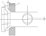
도 1은 본 발명에 따른 머시닝센터의 스핀들과 트윈암의 편심량 측정장치 의 구성도이다.
도 2는 본 발명에 따른 머시닝센터의 스핀들과 트윈암의 편심량 측정장치 의 설치 상태도이다.
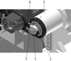
도 3은 본 발명에 따른 머시닝센터의 스핀들과 트윈암의 편심량 측정장치 의 설치 상태를 보여주는 요부 확대도이다.
도 4는 본 발명에 따른 머시닝센터의 스핀들과 트윈암의 편심량 측정장치 의 설치상태를 보여주는 단면도이다.
도 5는 본 발명에 따른 머시닝센터의 스핀들과 트윈암의 편심량 측정장치 의 설치상태를 보여주는 요부 단면도이다.
도 6은 본 발명에 따른 머시닝센터의 스핀들과 트윈암의 편심량 측정장치 의 편심시 요부 단면도이다.
도 7은 본 발명에 따른 머시닝센터의 스핀들과 트윈암의 편심량 측정장치 의 측정원리를 설명하기 위한 도면이다.1 is a configuration diagram of an apparatus for measuring the eccentricity of a spindle and a twin arm of a machining center according to the present invention.
FIG. 2 is an installation view of an apparatus for measuring the eccentricity of a spindle and a twin arm of a machining center according to the present invention.
3 is an enlarged view showing an installation state of a spindle and a twin arm eccentricity measuring device of a machining center according to the present invention.
4 is a sectional view showing the installation state of the eccentricity measuring device of the spindle and the twin arm of the machining center according to the present invention.
FIG. 5 is a sectional view showing the main part showing the installation state of the eccentricity measuring device for the spindle and the twin arm of the machining center according to the present invention.
6 is a cross-sectional view of a main part of the eccentricity measuring device for measuring the eccentricity of a spindle and a twin arm of a machining center according to the present invention.
7 is a view for explaining a measurement principle of an apparatus for measuring the eccentricity of a spindle and a twin arm of a machining center according to the present invention.
이하, 본 발명의 바람직한 실시예를 첨부된 도면을 참조로 하여 상세히 설명한다. Hereinafter, preferred embodiments of the present invention will be described in detail with reference to the accompanying drawings.
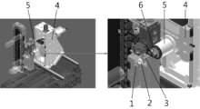
본 발명에 따른 머시닝센터의 스핀들과 트윈암의 편심량 측정장치의 구성은, 도 1 내지 도 5에 도시되어 있는 바와 같이, 링형태로 이루어지며 일측에 손잡이홈(11)이 형성되어 있으며 타측에 결합을 위한 경사 돌기부(12)가 형성되어 있는 제1 치구(1)와, 링형태로 이루어지며 내주면에 상기한 제1 치구(1)의 경사 돌기부(12)와 결합되는 경사홈(21)이 형성되어 있으며 외주면에 트윈암 그리퍼(6)가 장착되기 위한 그리퍼홈(22)이 형성되어 있는 제2 치구(2)와, 일단은 스핀들(5)에 결합되며 타단은 상기한 제1 치구(1) 및 제2 치구(2)를 관통하여 결합되는 제3 치구(3)를 포함하여 이루어진다.As shown in Figs. 1 to 5, the spindle and twin arm eccentricity measuring device of the present invention are formed in a ring shape and have a
상기한 제2 치구(2)를 트윈암 그리퍼(6)에 장착한 경우에, 링형태의 제2 치구(2)의 원중심은 반원형태의 트윈암 그리퍼(1)의 원중심과 동심을 이루게 되는 구조로 이루어진다.When the
상기한 제3 치구(3)를 스핀들(5)에 장착한 경우에, 축형태의 제3 치구(3)의 축중심은 스핀들(5)의 축중심과 동심을 이루게 되는 구조로 이루어진다. When the
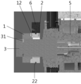
상기한 제3 치구(3)는 중간에 단차부(32)가 형성되어 있으며 제1 치구(1)와 결합되는 부위에 위치확인홈(31)이 형성되어 있는 구조로 이루어진다.The
상기한 구성에 의한, 본 발명에 따른 머시닝센터의 스핀들과 트윈암의 편심량 측정장치 및 방법의 작용은 다음과 같다.The operation and effects of the apparatus and method for measuring the eccentricity of the spindle and the twin arm of the machining center according to the present invention are as follows.
컬럼(4)에 설치되어 있는 스핀들(5)에 제3 치구(3)를 결합한 후에, 상기한 제3 치구(3)에 제2 치구(2)를 장착하면서 상기한 제2 치구(2)가 트윈암 그리퍼(6)에 장착되도록 한다. 이 경우에, 제3 치구(3)의 축중심은 스핀들(5)의 축중심과 동심을 형성하고 제2 치구(2)의 원중심은 트윈암 그리퍼(6)의 원중심과 동심을 형성하게 된다.The
이어서, 제3 치구(3)에 제1 치구(1)가 관통 결합되도록 한 뒤에, 제1 치구(1)의 경사 돌기부(12)와 제2 치구(2)의 경사홈(21)이 결합되도록 끼운다. Then, after the
이 상태에서, 만약 스핀들(5)의 축중심과 트윈암 그리퍼(6)의 원중심이 동심을 형성하지 못하고 편심되어 있다면, 스핀들(5)과 동심을 형성하며 결합되어 있는 제3 치구(3)의 중심과, 트윈암 그리퍼(6)와 동심을 형성하며 결합되어 있는 제2 치구(2)의 중심이 편심된다. In this state, if the axial center of the
이와 같이 제3 치구(3)의 중심과 제2 치구(2)의 중심이 편심되면, 도 6에 도시되어 있는 바와 같이, 제1 치구(1)의 경사 돌기부(12)가 제2 치구(2)의 경사홈((22)과 밀착결합되지 못하고, 편심량(E)만큼 이격되어 결합된다.6, when the center of the
상기한 편심량(E)은 다음과 같은 수식에 의해 구체적으로 계산된다.The eccentricity amount E is specifically calculated by the following equation.
E = TOTAL LENGTH - (K1 + K2 + K3 + M1 + M2)E = TOTAL LENGTH - (K1 + K2 + K3 + M1 + M2)
여기서, TOTAL LENGTH 은 제3 치구(1)의 단차부(32)에서부터 시작하여 제2 치구(2) 및 제1 치구(1)와 결합되는 부위의 축방향 길이이고, K1, K2, K3는 가공에 의해 구속된 가공값이고, M1, M2는 측정기를 사용하여 측정한 측정값이다.Here, TOTAL LENGTH is the axial length of a portion to be engaged with the
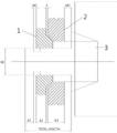
이와 같이 계산된 편심량(E)을 바탕으로 두 축간 편심된 거리를 2축으로 성분을 분리한다. 이때 주의해야 할 점은 공작기계 자체의 이송축과 편심량의 이동좌표가 일치해야 한다.Based on the calculated eccentricity (E), components are separated in two axes by the distance between the two axes. It should be noted that the movement axis of the eccentricity and the feed axis of the machine tool itself must coincide with each other.
다음에, 도 7에 도시되어 있는 바와 같이, 편심량(E)의 성분 분리를 위해, 두 축중 임의의 축방향으로, 이송거리(F)만큼 P1에서 P2로 이송시켜서 이차 편심량(E2)을 다시 측정한다.Next, as shown in Fig. 7, in order to separate the component of the eccentric quantity E, the secondary eccentricity E2 is measured again by feeding the product from P1 to P2 by the feed distance F in an arbitrary axial direction of the two axes do.
이어서, 편심량(E)과 이송거리(F)의 사이의 각도(α)를 계산한 후, 코사인 제2 법칙을 사용하여 각 축방향으로 발생된 편심량을 계산한다.Subsequently, the angle? Between the eccentricity amount E and the feed distance F is calculated, and then the amount of eccentricity generated in each axial direction is calculated using the cosine second law.
이상에서 제시된 실시예는 여러가지 실시가능한 예중에서 당업자의 이해를 돕기 위하여 가장 바람직한 실시예를 선정하여 제시한 것일 뿐, 본 발명의 기술적 사상이 반드시 제시된 실시예에만 의해서 한정되거나 제한되는 것은 아니고, 본 발명의 기술적 사상을 벗어나지 않는 범위내에서 다양한 변화와 부가 및 변경이 가능함은 물론, 균등한 타의 실시예가 가능하다. While the present invention has been described in connection with what is presently considered to be practical exemplary embodiments, it is to be understood that the invention is not limited to the disclosed embodiments, but, on the contrary, It will be understood by those skilled in the art that various changes in form and details may be made therein without departing from the spirit and scope of the invention as defined in the appended claims.
1 : 제1 치구 2 : 제2 치구
3 : 제3 치구 4 : 컬럼
5 : 스핀들 6 : 트윈암 그리퍼1: first jig 2: second jig
3: Third jig 4: Column
5: Spindle 6: Twin arm gripper
Claims (6)
링형태로 이루어지며 내주면에 상기한 제1 치구의 경사 돌기부와 결합되는 경사홈이 형성되어 있으며 외주면에 트윈암 그리퍼가 장착되기 위한 그리퍼홈이 형성되어 있는 제2 치구; 및
일단은 스핀들에 결합되며 타단은 상기한 제1 치구 및 제2 치구를 관통하여 결합되는 제3 치구를 포함하는 머시닝센터의 스핀들과 트윈암의 편심량 측정장치. A first jig having a ring shape and formed with a knob groove on one side and an inclined projection for coupling on the other side;
A second jig having a ring shape and having an inclined groove to be engaged with the inclined projection of the first jig on an inner circumferential surface thereof and a gripper groove for mounting a twin arm gripper on an outer circumferential surface thereof; And
And a third jig, one end of which is coupled to the spindle and the other end that is coupled through the first jig and the second jig, and the eccentricity of the spindle and twin arm of the machining center.
상기한 제2 치구를 트윈암 그리퍼에 장착한 경우에, 링형태의 제2 치구의 원중심은 반원형태의 트윈암 그리퍼의 원중심과 동심을 이루는 머시닝센터의 스핀들과 트윈암의 편심량 측정장치. The method according to claim 1,
Wherein the center of the circle of the second jig is concentric with the center of the circle of the twin arm gripper when the second jig is mounted on the twin arm gripper.
상기한 제3 치구를 스핀들에 장착한 경우에, 축형태의 제3 치구의 축중심은 스핀들의 축중심과 동심을 이루는 머시닝센터의 스핀들과 트윈암의 편심량 측정장치. The method according to claim 1,
Wherein the shaft center of the third jig having a shaft shape is concentric with the shaft center of the spindle when the third jig is mounted on the spindle.
상기한 제3 치구는 중간에 단차부가 형성되어 있으며 제1 치구와 결합되는 부위에 위치확인홈이 형성되어 있는 머시닝센터의 스핀들과 트윈암의 편심량 측정장치.The method according to claim 1,
Wherein the third jig has a stepped portion formed at an intermediate portion thereof and a positioning groove is formed at a portion to be coupled with the first jig, wherein the positioning jig is formed in the spindle and the twin arm.
계산된 편심량(E)을 바탕으로 두 축간 편심된 거리를 2축으로 성분을 분리하는 단계;
편심량(E)의 성분 분리를 위해, 두 축중 임의의 축방향으로, 이송거리(F)만큼 P1에서 P2로 이송시켜서 이차 편심량(E2)을 다시 측정하는 단계; 및
편심량(E)과 이송거리(F)의 사이의 각도(α)를 계산한 후, 코사인 제2 법칙을 사용하여 각 축방향으로 발생된 편심량을 계산하는 단계를 포함하는 머시닝센터의 스핀들과 트윈암의 편심량 측정방법.A first jig having a ring shape and formed with a knob groove on one side and an inclined projection for engaging on the other side; and a slant groove, which is formed in a ring shape and engages with the slant projection of the first jig, A second jig having a gripper groove for mounting a twin arm gripper on an outer circumferential surface thereof and a third jig having one end coupled to the spindle and the other end coupled to the first jig and the second jig Measuring and calculating an eccentricity (E);
Separating the components by biaxial distances between the two axes based on the calculated eccentricity (E);
Measuring the secondary eccentricity E2 again by feeding from P1 to P2 by the feed distance F in an arbitrary axial direction of the two axes for component separation of the eccentricity E; And
Calculating an angle? Between the eccentricity amount (E) and the feed distance (F) and calculating an eccentricity amount generated in each axial direction by using a cosine second law; Of the eccentricity.
상기한 편심량(E)은 다음 수식에 의해 계산되는 머시닝센터의 스핀들과 트윈암의 편심량 측정방법.
E = TOTAL LENGTH - (K1 + K2 + K3 + M1 + M2)
여기서, TOTAL LENGTH 은 제3 치구(1)의 단차부(32)에서부터 시작하여 제2 치구(2) 및 제1 치구(1)와 결합되는 부위의 축방향 길이이고, K1, K2, K3는 가공에 의해 구속된 가공값이고, M1, M2는 측정기를 사용하여 측정한 측정값이다.6. The method of claim 5,
Wherein the eccentricity amount (E) is calculated by the following equation: < EMI ID = 1.0 >
E = TOTAL LENGTH - (K1 + K2 + K3 + M1 + M2)
Here, TOTAL LENGTH is the axial length of a portion to be engaged with the second jig 2 and the first jig 1 starting from the stepped portion 32 of the third jig 1, and K1, K2, And M1 and M2 are measured values measured using a measuring device.
Priority Applications (1)
| Application Number | Priority Date | Filing Date | Title |
|---|---|---|---|
| KR1020130131832A KR20150050795A (en) | 2013-10-31 | 2013-10-31 | Device for measuring eccentric quantity between spindle and twin arm of machining center |
Applications Claiming Priority (1)
| Application Number | Priority Date | Filing Date | Title |
|---|---|---|---|
| KR1020130131832A KR20150050795A (en) | 2013-10-31 | 2013-10-31 | Device for measuring eccentric quantity between spindle and twin arm of machining center |
Publications (1)
| Publication Number | Publication Date |
|---|---|
| KR20150050795A true KR20150050795A (en) | 2015-05-11 |
Family
ID=53388454
Family Applications (1)
| Application Number | Title | Priority Date | Filing Date |
|---|---|---|---|
| KR1020130131832A KR20150050795A (en) | 2013-10-31 | 2013-10-31 | Device for measuring eccentric quantity between spindle and twin arm of machining center |
Country Status (1)
| Country | Link |
|---|---|
| KR (1) | KR20150050795A (en) |
Cited By (2)
| Publication number | Priority date | Publication date | Assignee | Title |
|---|---|---|---|---|
| CN107525488A (en) * | 2017-08-18 | 2017-12-29 | 青岛海尔洗衣机有限公司 | A kind of washing machine and eccentric detection method with fine motion ring |
| CN114526704A (en) * | 2022-01-30 | 2022-05-24 | 安徽英克尔汽车零部件有限公司 | Method for detecting circumferential clearance of ball cage type constant-speed transmission shaft assembly |
-
2013
- 2013-10-31 KR KR1020130131832A patent/KR20150050795A/en not_active Application Discontinuation
Cited By (4)
| Publication number | Priority date | Publication date | Assignee | Title |
|---|---|---|---|---|
| CN107525488A (en) * | 2017-08-18 | 2017-12-29 | 青岛海尔洗衣机有限公司 | A kind of washing machine and eccentric detection method with fine motion ring |
| CN107525488B (en) * | 2017-08-18 | 2021-08-27 | 青岛胶南海尔洗衣机有限公司 | Washing machine with micro-moving ring and eccentricity detection method |
| CN114526704A (en) * | 2022-01-30 | 2022-05-24 | 安徽英克尔汽车零部件有限公司 | Method for detecting circumferential clearance of ball cage type constant-speed transmission shaft assembly |
| CN114526704B (en) * | 2022-01-30 | 2024-02-23 | 安徽英克尔汽车零部件有限公司 | Circumferential gap detection method for ball cage type constant-speed transmission shaft assembly |
Similar Documents
| Publication | Publication Date | Title |
|---|---|---|
| CN103894800B (en) | The processing method of candan universal joint jaw and fixture thereof | |
| CN104400335A (en) | Taper sleeve processing method | |
| TWI694878B (en) | Working machine and processing method of working machine | |
| CN101972861B (en) | Method for processing inclined hole on cylindrical surface of numerical control machine tool | |
| CN203141109U (en) | Special tool for processing spindle radial hole | |
| KR101368761B1 (en) | Machining process of flange yoke | |
| KR20150050795A (en) | Device for measuring eccentric quantity between spindle and twin arm of machining center | |
| CN201833192U (en) | Clamping device for processing inclined hole on cylindrical surface of shaft | |
| KR20160015678A (en) | Revolving device for tool holder for machining center | |
| KR20090082206A (en) | Clamping method for workpieces used for the production of compressor or turbine wheels | |
| CN103769955B (en) | Multistation vertical rotary building-block machine | |
| CN103753155B (en) | A kind of hydraulic turbine annular piston processing technology and machining tool thereof | |
| CN103978256A (en) | Method and tool for machining arc-shaped groove in batches by using lathe | |
| JP2009255189A (en) | Tool changing system of machining center | |
| CN105537656A (en) | Double-sided special key slot milling machine | |
| CN105033312A (en) | Glass mold clamping and rotating device matching numerical control machining machine | |
| CN111906392B (en) | Automatic threading machine and threading method for production of connecting piece | |
| CN202556111U (en) | Self-centering flexible drill shank | |
| CN203621518U (en) | Pendulum mass rotatable turning processing device | |
| CN103464785B (en) | The turning cutting-off method of rod-shaped workpiece | |
| KR101345946B1 (en) | Clamping device for table of machining center | |
| CN204381978U (en) | Numerical Control Cam automatic processing center | |
| CN111618538A (en) | Method for machining guide vane outer ring guide vane hole of through-flow turbine | |
| JP2003062701A (en) | Cnc lathe with counter spindle | |
| CN201366626Y (en) | Fixture for surfacing |
Legal Events
| Date | Code | Title | Description |
|---|---|---|---|
| WITN | Withdrawal due to no request for examination |