KR20150020953A - Method and apparatus for processing images - Google Patents
Method and apparatus for processing images Download PDFInfo
- Publication number
- KR20150020953A KR20150020953A KR20130098134A KR20130098134A KR20150020953A KR 20150020953 A KR20150020953 A KR 20150020953A KR 20130098134 A KR20130098134 A KR 20130098134A KR 20130098134 A KR20130098134 A KR 20130098134A KR 20150020953 A KR20150020953 A KR 20150020953A
- Authority
- KR
- South Korea
- Prior art keywords
- pixel
- point
- depth
- depth value
- image
- Prior art date
Links
- 238000000034 method Methods 0.000 title claims abstract description 97
- 238000012545 processing Methods 0.000 title claims abstract description 18
- 238000003709 image segmentation Methods 0.000 claims abstract description 42
- 238000003672 processing method Methods 0.000 claims abstract description 32
- 238000010586 diagram Methods 0.000 description 46
- 230000003287 optical effect Effects 0.000 description 4
- 239000003086 colorant Substances 0.000 description 3
- 238000001514 detection method Methods 0.000 description 2
- 238000002372 labelling Methods 0.000 description 2
- 238000013507 mapping Methods 0.000 description 2
- 238000011160 research Methods 0.000 description 2
- 238000006243 chemical reaction Methods 0.000 description 1
- 238000012937 correction Methods 0.000 description 1
- 238000005516 engineering process Methods 0.000 description 1
- 210000004905 finger nail Anatomy 0.000 description 1
- 238000009499 grossing Methods 0.000 description 1
- 238000005259 measurement Methods 0.000 description 1
- 238000012805 post-processing Methods 0.000 description 1
- 238000013139 quantization Methods 0.000 description 1
- 230000001131 transforming effect Effects 0.000 description 1
Images


Classifications
-
- G—PHYSICS
- G06—COMPUTING; CALCULATING OR COUNTING
- G06T—IMAGE DATA PROCESSING OR GENERATION, IN GENERAL
- G06T3/00—Geometric image transformations in the plane of the image
- G06T3/40—Scaling of whole images or parts thereof, e.g. expanding or contracting
-
- G—PHYSICS
- G06—COMPUTING; CALCULATING OR COUNTING
- G06T—IMAGE DATA PROCESSING OR GENERATION, IN GENERAL
- G06T3/00—Geometric image transformations in the plane of the image
- G06T3/40—Scaling of whole images or parts thereof, e.g. expanding or contracting
- G06T3/4053—Scaling of whole images or parts thereof, e.g. expanding or contracting based on super-resolution, i.e. the output image resolution being higher than the sensor resolution
- G06T3/4061—Scaling of whole images or parts thereof, e.g. expanding or contracting based on super-resolution, i.e. the output image resolution being higher than the sensor resolution by injecting details from different spectral ranges
-
- G—PHYSICS
- G06—COMPUTING; CALCULATING OR COUNTING
- G06F—ELECTRIC DIGITAL DATA PROCESSING
- G06F18/00—Pattern recognition
- G06F18/20—Analysing
- G06F18/24—Classification techniques
-
- G—PHYSICS
- G06—COMPUTING; CALCULATING OR COUNTING
- G06T—IMAGE DATA PROCESSING OR GENERATION, IN GENERAL
- G06T5/00—Image enhancement or restoration
-
- G—PHYSICS
- G06—COMPUTING; CALCULATING OR COUNTING
- G06T—IMAGE DATA PROCESSING OR GENERATION, IN GENERAL
- G06T7/00—Image analysis
- G06T7/10—Segmentation; Edge detection
- G06T7/11—Region-based segmentation
-
- G—PHYSICS
- G06—COMPUTING; CALCULATING OR COUNTING
- G06T—IMAGE DATA PROCESSING OR GENERATION, IN GENERAL
- G06T7/00—Image analysis
- G06T7/50—Depth or shape recovery
-
- H—ELECTRICITY
- H04—ELECTRIC COMMUNICATION TECHNIQUE
- H04N—PICTORIAL COMMUNICATION, e.g. TELEVISION
- H04N13/00—Stereoscopic video systems; Multi-view video systems; Details thereof
-
- G—PHYSICS
- G06—COMPUTING; CALCULATING OR COUNTING
- G06T—IMAGE DATA PROCESSING OR GENERATION, IN GENERAL
- G06T2200/00—Indexing scheme for image data processing or generation, in general
- G06T2200/04—Indexing scheme for image data processing or generation, in general involving 3D image data
-
- G—PHYSICS
- G06—COMPUTING; CALCULATING OR COUNTING
- G06T—IMAGE DATA PROCESSING OR GENERATION, IN GENERAL
- G06T2207/00—Indexing scheme for image analysis or image enhancement
- G06T2207/10—Image acquisition modality
- G06T2207/10028—Range image; Depth image; 3D point clouds
-
- G—PHYSICS
- G06—COMPUTING; CALCULATING OR COUNTING
- G06T—IMAGE DATA PROCESSING OR GENERATION, IN GENERAL
- G06T2207/00—Indexing scheme for image analysis or image enhancement
- G06T2207/20—Special algorithmic details
- G06T2207/20212—Image combination
- G06T2207/20221—Image fusion; Image merging
Landscapes
- Engineering & Computer Science (AREA)
- Physics & Mathematics (AREA)
- Theoretical Computer Science (AREA)
- General Physics & Mathematics (AREA)
- Computer Vision & Pattern Recognition (AREA)
- Spectroscopy & Molecular Physics (AREA)
- Data Mining & Analysis (AREA)
- Bioinformatics & Cheminformatics (AREA)
- Artificial Intelligence (AREA)
- Bioinformatics & Computational Biology (AREA)
- Life Sciences & Earth Sciences (AREA)
- Evolutionary Biology (AREA)
- Evolutionary Computation (AREA)
- General Engineering & Computer Science (AREA)
- Multimedia (AREA)
- Signal Processing (AREA)
- Image Analysis (AREA)
Abstract
Description
본 발명의 실시예는 영상 처리 방법 및 영상 처리 장치에 관한 것으로서, 보다 상세하게는 깊이 맵의 해상도보다 더 높은 해상도를 갖는 색상 영상을 이용하여 상기 깊이 맵의 해상도를 상기 색상 영상의 해상도로 업샘플링할 수 있는 영상 처리 방법 및 영상 처리에 관한 것이다.An embodiment of the present invention relates to an image processing method and an image processing apparatus, and more particularly, to an image processing method and an image processing apparatus that upsample a resolution of a depth map using a color image having a resolution higher than a resolution of a depth map, And more particularly, to an image processing method and an image processing method capable of performing image processing.
전통적으로 2차원 영상을 촬영하는 카메라에 대한 연구가 많이 진행되었고, 관련 제품도 다수 출시되었다. 종래에는 아날로그 방식의 카메라가 주로 이용되었으나 최근 들어서는 디지털 방식의 카메라가 널리 이용되고 있다. 디지털 카메라에 대한 연구 역시 활발하다. 높은 해상도 및 높은 품질을 가진 사진을 용이하게 촬영할 수 있는 디지털 카메라에 대한 연구가 계속되고 있다.Traditionally, there have been a lot of researches on cameras that shoot 2D images, and many related products have been released. Conventionally, analog type cameras are mainly used, but in recent years, digital type cameras have been widely used. Research on digital cameras is also active. A study on a digital camera which can easily photograph a photograph having a high resolution and a high quality is continuing.
최근에는 3차원 표시 장치의 보급과 더불어 3차원 촬영 장치에 대한 수요가 늘고 있다. 다양한 종류의 3차원 카메라가 판매되고 있으며, 3차원 카메라를 활용한 기술도 발전하고 있다.In recent years, along with the spread of the three-dimensional display device, the demand for the three-dimensional photographing device is increasing. Various types of 3D cameras are being sold, and technologies utilizing 3D cameras are also being developed.
예를 들어, 조이스틱 등의 물리적인 컨트롤러 없이 사람의 제스처(gesture)를 이용하여 전자 장치를 제어할 수 있는 기술이 소개되었다. 또한, 3차원 카메라 덕분에 장면(scene) 또는 사물의 3차원 모델을 생성하는 일도 종래에 비해 훨씬 용이해졌다.For example, techniques have been introduced that can control an electronic device using a person's gesture without a physical controller such as a joystick. Also, thanks to the three-dimensional camera, it is much easier to create a three-dimensional model of a scene or object than in the prior art.
3차원 카메라는 대상의 표면의 3차원 위치 정보를 실시간으로 제공할 수 있다는 장점을 갖는다. 그러나, 일반적으로 3차원 카메라는 2차원 카메라에 비해 낮은 해상도를 갖는다. 현재까지 상용화된 3차원 카메라 중에서 해상도가 가장 높은 제품의 해상도는 320 * 240 화소이다. 이는 풀 HD(full HD) 해상도(1920 * 1080)의 1/27배 정도이다.The three-dimensional camera has an advantage that it can provide three-dimensional position information of the surface of the object in real time. However, in general, a three-dimensional camera has a lower resolution than a two-dimensional camera. Among the 3D cameras commercialized so far, the resolution of the highest resolution product is 320 * 240 pixels. This is about 1/27 times the full HD resolution (1920 * 1080).
또한, 최근의 3차원 카메라들은 깊이를 감지하는 센서뿐만 아니라 색상을 감지하는 카메라도 포함하고 있다. 이로써, 장면의 3차원 깊이 정보와 함께 장면의 고해상도 색상 정보가 제공될 수 있다.In addition, recent 3D cameras include not only a sensor for sensing depth but also a camera for detecting color. Thus, the high-resolution color information of the scene can be provided together with the three-dimensional depth information of the scene.
본 발명의 실시예는 깊이 맵의 해상도보다 더 높은 해상도를 갖는 색상 영상을 이용하여 상기 깊이 맵의 해상도를 상기 색상 영상의 해상도로 업샘플링할 수 있는 영상 처리 방법 및 영상 처리를 제공할 수 있다.The embodiment of the present invention can provide an image processing method and an image processing method capable of upsampling the resolution of the depth map to the resolution of the color image using a color image having a higher resolution than the resolution of the depth map.
본 발명의 실시예는 대상에 대한 깊이 맵에서의 경계가 대상에 대한 색상 영상에서의 경계와 일치하도록 상기 깊이 맵을 업샘플링할 수 있는 영상 처리 방법 및 영상 처리를 제공할 수 있다.An embodiment of the present invention may provide an image processing method and an image processing method capable of upsampling the depth map such that the boundary in the depth map for the object matches the boundary in the color image for the object.
본 발명의 실시예는 깊이 맵의 해상도를 상기 해상도보다 더 높은 해상도로 업샘플링할 수 있는 영상 처리 방법 및 영상 처리를 제공할 수 있다.Embodiments of the present invention can provide an image processing method and an image processing method capable of upsampling a resolution of a depth map to a resolution higher than the resolution.
본 발명의 실시예는 시점의 위치 및 방향이 유사한 깊이 센서 및 색상 카메라를 통해 각각 수신된 깊이 맵 및 색상 영상을 이용하여, 상기 색상 영상의 시점 및 해상도와 동일한 시점 및 해상도를 갖는 깊이 맵을 생성할 수 있는 영상 처리 방법 및 영상 처리 장치를 제공할 수 있다.The embodiment of the present invention generates a depth map having the same viewpoint and resolution as the viewpoint and resolution of the color image using the depth map and the color image received through the depth sensor and the color camera, It is possible to provide an image processing method and an image processing apparatus that can be used.
본 발명의 기술적 과제들은 이상에서 언급한 기술적 과제들로 제한되지 않으며, 언급되지 않은 또 다른 기술적 과제들은 아래의 기재로부터 당업자에게 명확하게 이해 될 수 있을 것이다.The technical objects of the present invention are not limited to the above-mentioned technical problems, and other technical subjects not mentioned can be clearly understood by those skilled in the art from the following description.
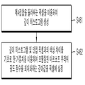
본 발명의 실시예에 따른 영상 처리 방법은, 특정한 장면(scene)에 대한 깊이 맵 및 색상 영상을 수신하는 단계, 상기 깊이 맵에 포함된 각각의 지점을 상기 색상 영상에 투영하는 단계, 상기 깊이 맵이 투영된 상기 색상 영상을 적어도 둘 이상의 영상 분할(image segmentation) 방법을 이용하여 분할함으로써 각각의 분할된 결과를 생성하고, 상기 각각의 분할된 결과에 따라 상기 색상 영상에 포함된 지점들을 적어도 하나 이상의 집합으로 분류하는 단계, 상기 집합에 포함된 상기 색상 영상의 지점에 깊이값을 설정하는 단계, 및 상기 깊이값이 설정된 상기 색상 영상을 출력하는 단계를 포함할 수 있다.The image processing method according to an embodiment of the present invention includes the steps of receiving a depth map and a color image for a specific scene, projecting each point included in the depth map onto the color image, And generating the divided result by dividing the projected color image by using at least two or more image segmentation methods and dividing the points included in the color image according to each divided result into at least one A step of classifying the color image into a set, a step of setting a depth value at a point of the color image included in the set, and a step of outputting the color image with the depth value set.
또한, 상기 깊이 맵의 해상도는 상기 색상 영상의 해상도보다 더 낮을 수 있다.In addition, the resolution of the depth map may be lower than the resolution of the color image.
또한, 상기 깊이 맵에 포함된 각각의 지점을 상기 색상 영상에 투영하는 단계는, 상기 깊이 맵의 각각의 제1지점의 깊이값 및 상기 제1지점과 서로 인접한 제2지점의 깊이값을 이용하여, 상기 제1지점 중에서 상기 제2지점과 서로 불연속하는 불연속 지점을 검출하는 단계, 상기 제1지점의 깊이값과 상기 제2지점의 깊이값의 차이 및 상기 제1지점을 이용하여 메쉬를 생성하는 단계, 및 상기 메쉬를 상기 색상 영상에 투영하는 단계를 포함할 수 있다.The step of projecting each of the points included in the depth map on the color image may further include using a depth value of each first point of the depth map and a depth value of a second point adjacent to the first point, Detecting a discontinuity point that is discontinuous with the second point in the first point, generating a mesh using the difference between the depth value of the first point and the depth value of the second point, And projecting the mesh onto the color image.
또한, 상기 제1지점 중에서 상기 제2지점과 서로 불연속하는 불연속 지점을 검출하는 단계는, 상기 제1지점의 깊이값과 상기 제2지점의 깊이값의 차이 또는 상기 장면 내에 존재하는 적어도 하나 이상의 객체 중에서 상기 제1지점에 대응되는 제1객체와 상기 제2지점에 대응되는 제2객체가 서로 동일한지 여부에 대한 판정결과를 이용하여 상기 불연속 지점을 검출하는 단계를 포함할 수 있다.The step of detecting a discontinuity point that is discontinuous with the second point among the first points may include detecting a difference between a depth value of the first point and a depth value of the second point, Detecting the discontinuity using a determination result of whether or not the first object corresponding to the first point and the second object corresponding to the second point are the same among the first object and the second object.
또한, 상기 제1지점 중에서 상기 제2지점과 서로 불연속하는 불연속 지점을 검출하는 단계는, 상기 깊이 맵의 각각의 제1지점에 대해 상기 제1지점의 접평면에 대응되는 벡터를 산출하는 단계, 상기 각각의 제1지점에 대해 상기 제1지점을 중심으로 한 특정한 범위의 영역 내에 포함된 적어도 하나 이상의 제3지점의 상기 벡터를 이용하여 계산된 상기 제1지점의 예상 깊이값과 상기 깊이 맵에 포함된 상기 제1지점의 깊이값의 차이 중에서 최소값을 산출하는 단계, 및 상기 제1지점의 깊이값, 상기 제2지점의 깊이값, 상기 제1지점의 상기 최소값 및 상기 제2지점의 상기 최소값을 이용하여 상기 제1지점 중에서 상기 제2지점과 서로 불연속하는 불연속 지점을 검출하는 단계를 포함할 수 있다.The step of detecting a discontinuity point that is discontinuous with the second point among the first points may include calculating a vector corresponding to a tangent plane of the first point with respect to each first point of the depth map, An estimated depth value of the first point calculated by using the vector of at least one third point included in a specific range of areas centered on the first point with respect to each first point, Calculating a depth value of the first point, a depth value of the second point, the minimum value of the first point, and the minimum value of the second point, based on the depth value of the first point, And detecting a discontinuity point in the first point that is discontinuous with the second point.
또한, 상기 메쉬를 생성하는 단계는, 상기 제1지점과 가로 방향으로 서로 인접한 제4지점을 상기 제1지점과 연결하는 단계, 상기 제1지점과 세로 방향으로 서로 인접한 상기 제5지점을 상기 제1지점과 연결하는 단계, 및 상기 제4지점의 깊이값과 상기 제5지점의 깊이값의 차이 및 상기 제4지점과 세로 방향으로 인접하고 상기 제5지점과 가로 방향으로 인접하는 제6지점의 깊이값과 상기 제1지점의 깊이값의 차이 중에서 더 작은 쪽에 대응되는 상기 지점들을 서로 연결하는 단계를 포함할 수 있다.The step of generating the mesh may further include connecting a fourth point adjacent to the first point to the first point and a fifth point adjacent to the first point in the longitudinal direction, And a step of connecting the fourth point to a depth of the fourth point and a depth value of the fifth point and a difference between a depth value of the fourth point and a depth value of the fifth point, And connecting the points corresponding to the smaller one of the difference between the depth value and the depth value of the first point to each other.
또한, 상기 색상 영상에 포함된 지점들을 적어도 하나 이상의 집합으로 분류하는 단계는, 상기 투영된 메쉬의 각각의 정점의 깊이값을 이용하여 상기 투영된 메쉬에 포함된 각각의 지점에 깊이값을 설정하는 단계, 상기 투영된 메쉬 중에서, 다른 메쉬에 의해 가려지는 적어도 하나 이상의 정점을 포함하는 적어도 하나 이상의 메쉬 및 상기 불연속 지점을 중심으로 한 특정한 범위의 영역을 포함하는 불연속 영역을 검출하는 단계, 상기 투영된 메쉬 중에서, 적어도 하나 이상의 상기 불연속 지점을 포함하는 적어도 하나 이상의 메쉬를 포함하는 홀(hole) 영역을 검출하는 단계, 상기 홀 영역의 내부에 적어도 하나 이상의 가상 정점을 생성하는 단계, 상기 적어도 둘 이상의 영상 분할 방법, 상기 정점 및 상기 가상 정점을 이용하여 상기 색상 영상을 분할하는 단계, 및 상기 각각의 분할된 결과에 따라 상기 색상 영상에 포함된 상기 지점들을 상기 집합으로 분류하는 단계를 포함할 수 있다.The step of classifying the points included in the color image into at least one or more sets may include the steps of setting a depth value at each point included in the projected mesh using the depth value of each vertex of the projected mesh Detecting at least one mesh including at least one vertex covered by another mesh and a discontinuity region including a specific range of areas centered at the discontinuity among the projected meshes, The method comprising: detecting, in a mesh, a hole region including at least one or more meshes including at least one discontinuity point, generating at least one virtual vertex in the hole region, And dividing the color image using the vertex and the virtual vertex It may phase, and according to the division result of each include the step of classifying said point included in the color image in the set.
또한, 상기 투영된 메쉬에 포함된 각각의 지점에 깊이값을 설정하는 단계는 상기 각각의 정점의 위치를 기초로 한 평면 방정식을 이용하여 상기 투영된 메쉬에 포함된 각각의 지점에 상기 깊이값을 보간하여 설정하는 단계, 및 상기 색상 영상에 포함된 지점 중에서 적어도 둘 이상의 상기 메쉬에 대응되는 지점에는, 상기 지점에 대응되는 상기 깊이값 중에서 가장 작은 깊이값을 설정하는 단계를 포함할 수 있다.The step of setting a depth value at each point included in the projected mesh may further include the step of calculating a depth value at each point included in the projected mesh using a plane equation based on the position of each vertex And setting a minimum depth value among the depth values corresponding to the points at a point corresponding to at least two or more meshes among the points included in the color image.
또한, 상기 적어도 둘 이상의 영상 분할 방법, 상기 정점 및 상기 가상 정점을 이용하여 상기 색상 영상을 분할하는 단계는, 제1 영상 분할 방법을 이용하여, 하나의 상기 정점 또는 하나의 상기 가상 정점을 포함하거나 상기 정점 및 상기 가상 정점을 포함하지 않는 적어도 하나 이상의 영역으로 상기 메쉬가 투영된 상기 색상 영상이 분할된 제1분할영상을 생성하는 단계, 및 상기 제1 영상 분할 방법과 서로 다른 제2 영상 분할 방법 이용하여 하나의 상기 정점 또는 하나의 상기 가상 정점을 포함하거나 상기 정점 및 상기 가상 정점을 포함하지 않는 적어도 하나 이상의 영역으로 상기 메쉬가 투영된 상기 색상 영상이 분할된 제2분할영상을 생성하는 단계를 포함할 수 있다.The step of dividing the color image using the at least two image segmentation methods, the vertices, and the virtual vertices may include one vertex or one virtual vertex using the first image segmentation method Generating a first divided image in which the color image projected from the mesh is divided into at least one region that does not include the vertex and the virtual vertex, and generating a second divided image, which is different from the first divided image, And generating a second divided image in which the color image is divided into at least one region including one vertex or one virtual vertex or not including the vertex and the virtual vertex, .
또한, 상기 각각의 분할된 결과에 따라 상기 색상 영상에 포함된 상기 지점들을 상기 집합으로 분류하는 단계는, 적어도 하나 이상의 영역으로 상기 깊이 맵이 분할된 제3분할영상을 생성하고, 상기 제3분할영상에 포함된 각각의 영역에 서로 다른 레이블을 설정하는 단계, 상기 제1분할영상에 포함된 각각의 영역에 포함된 상기 정점에 대응되는 상기 제3분할영상의 영역에 설정된 상기 레이블에 대응하는 레이블을 상기 제1분할영상에 포함된 각각의 영역에 설정하는 단계, 상기 제2분할영상에 포함된 각각의 영역에 포함된 상기 정점에 대응되는 상기 제3분할영상의 영역에 설정된 상기 레이블에 대응하는 레이블을 상기 제2분할영상에 포함된 각각의 영역에 설정하는 단계, 및 상기 제1분할영상에 포함된 각각의 제1픽셀 중에서, 상기 제1픽셀에 대응되는 상기 레이블이 상기 제1픽셀에 대응되는 상기 제2분할영상의 제2픽셀에 대응되는 상기 레이블과 서로 동일한 적어도 하나 이상의 상기 제1픽셀을 포함하는 제1집합을 생성하는 단계를 포함할 수 있다.The step of classifying the points included in the color image into the set according to the respective divided results may include generating a third divided image in which the depth map is divided into at least one region, The method of
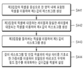
또한, 상기 집합에 포함된 상기 색상 영상의 지점에 깊이값을 설정하는 단계는, 상기 제1집합에 포함된 각각의 제3픽셀에 대하여, 상기 제3픽셀의 색상 및 상기 제3픽셀의 위치를 기초로 하여 깊이 히스토그램이 생성되고 상기 깊이 히스토그램의 피크(peak)에 대응되는 상기 깊이값이 상기 제3픽셀의 깊이값으로서 설정되는 단계를 포함할 수 있다.In addition, the step of setting a depth value at a point of the color image included in the set may include calculating a color of the third pixel and a position of the third pixel with respect to each third pixel included in the first set And a depth histogram corresponding to a peak of the depth histogram is set as a depth value of the third pixel.
또한, 상기 집합에 포함된 상기 색상 영상의 지점에 깊이값을 설정하는 단계는, 상기 제1집합에 포함된 각각의 제3픽셀에 대하여, 상기 제3픽셀을 중심으로 한 특정한 범위의 영역 내에 포함되고 상기 깊이값이 설정된 적어도 하나 이상의 제4픽셀의 상기 깊이값, 상기 제3픽셀과 상기 제4픽셀의 위치 차이 및 상기 제3픽셀과 상기 제4픽셀의 색상 차이를 이용하여 제1 깊이 히스토그램이 생성되는 단계, 상기 제3픽셀에 대응하는 레이블과 서로 동일한 레이블에 대응되는 적어도 하나 이상의 제5픽셀의 상기 깊이값, 상기 제3픽셀과 상기 제5픽셀의 위치 차이 및 상기 제3픽셀과 상기 제5픽셀의 색상 차이를 이용하여 제2 깊이 히스토그램이 생성되는 단계, 및 상기 제1 깊이 히스토그램 및 상기 제2 깊이 히스토그램에 가중치가 적용되어 합산된 결과의 피크(peak)에 대응되는 상기 깊이값이 상기 제3픽셀의 깊이값으로서 설정되는 단계를 포함할 수 있다.In addition, the step of setting a depth value at a point of the color image included in the set may include, for each third pixel included in the first set, within a specific range area centered on the third pixel The depth value of at least one or more fourth pixels having the depth value set therein, the position difference between the third pixel and the fourth pixel, and the color difference between the third pixel and the fourth pixel, The depth value of the at least one fifth pixel corresponding to the same label as the label corresponding to the third pixel, the positional difference between the third pixel and the fifth pixel, Wherein the first depth histogram and the second depth histogram are weighted to produce a resultant peak pea k may be set as the depth value of the third pixel.
또한, 상기 각각의 분할된 결과에 따라 상기 색상 영상에 포함된 상기 지점들을 상기 집합으로 분류하는 단계는, 상기 제1픽셀 중에서, 상기 제1픽셀에 대응되는 상기 영역 또는 상기 제1픽셀에 대응되는 상기 제2픽셀에 대응되는 상기 영역 중에서 적어도 하나 이상이 상기 가상 정점을 포함하는 적어도 하나 이상의 상기 제1픽셀을 포함하는 제2집합을 생성하는 단계를 더 포함할 수 있다.In addition, the step of classifying the points included in the color image into the set according to the respective divided results may further include a step of classifying the points corresponding to the first pixel or the region corresponding to the first pixel among the first pixels And generating a second set in which at least one of the regions corresponding to the second pixel includes at least one of the first pixels including the virtual vertices.
또한, 상기 집합에 포함된 상기 색상 영상의 지점에 깊이값을 설정하는 단계는, 상기 제2집합에 포함된 각각의 제6픽셀은, 상기 제6픽셀의 색상 및 상기 제6픽셀의 위치를 기초로 하여 선택되고 상기 깊이값이 설정된 하나의 제7픽셀을 포함하는 적어도 하나 이상의 서브집합으로 분할되고, 상기 각각의 제6픽셀의 깊이값으로서 상기 제6픽셀이 포함된 상기 서브집합에 포함된 상기 제7픽셀의 깊이값이 설정되는 단계를 포함할 수 있다.The step of setting a depth value at a point of the color image included in the set may include the step of setting a depth value at a point of the color image based on the color of the sixth pixel and the position of the sixth pixel, And the sixth pixel is divided into at least one subset including a seventh pixel set with the depth value, and the subset including the sixth pixel as the depth value of each sixth pixel, And a depth value of the seventh pixel is set.
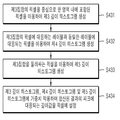
또한, 상기 각각의 분할된 결과에 따라 상기 색상 영상에 포함된 상기 지점들을 상기 집합으로 분류하는 단계는, 상기 각각의 제1픽셀 중에서, 상기 제1픽셀에 대응되는 상기 레이블이 상기 제1픽셀에 대응되는 상기 제2픽셀에 대응되는 상기 레이블과 서로 다르고, 상기 제1픽셀에 대응되는 상기 영역 또는 상기 제1픽셀에 대응되는 상기 제2픽셀에 대응되는 상기 영역 중에서 적어도 하나 이상이 상기 정점을 포함하는 적어도 하나 이상의 상기 제1픽셀을 포함하는 제3집합을 생성하는 단계를 더 포함할 수 있다.In addition, the step of classifying the points included in the color image according to the divided result into the set may include: determining whether the label corresponding to the first pixel among the first pixels is included in the first pixel Wherein at least one of the region corresponding to the first pixel or the region corresponding to the second pixel corresponding to the first pixel is different from the label corresponding to the corresponding second pixel, And generating a third set of at least one of the first pixels.
또한, 상기 집합에 포함된 상기 색상 영상의 지점에 깊이값을 설정하는 단계는, 상기 제3집합에 포함된 각각의 제8픽셀에 대하여, 상기 제8픽셀을 중심으로 한 특정한 범위의 영역 내에 포함되고 상기 깊이값이 설정된 적어도 하나 이상의 제9픽셀의 상기 깊이값, 상기 제8픽셀과 상기 제9픽셀의 위치 차이 및 상기 제8픽셀과 상기 제9픽셀의 색상 차이를 이용하여 제3 깊이 히스토그램이 생성되는 단계, 상기 제8픽셀에 대응하는 레이블과 서로 동일한 레이블에 대응되는 적어도 하나 이상의 제10픽셀의 상기 깊이값, 상기 제8픽셀과 상기 제10픽셀의 위치 차이 및 상기 제8픽셀과 상기 제10픽셀의 색상 차이를 이용하여 제4 깊이 히스토그램이 생성되는 단계, 상기 제3집합을 둘러싸고 상기 깊이값이 설정된 적어도 하나 이상의 제11픽셀의 상기 깊이값, 상기 제8픽셀과 상기 제11픽셀의 위치 차이 및 상기 제8픽셀과 상기 제11픽셀의 색상 차이를 이용하여 제5 깊이 히스토그램이 생성되는 단계, 및 상기 제3 깊이 히스토그램, 상기 제4 깊이 히스토그램 및 상기 제5 깊이 히스토그램에 가중치가 적용되어 합산된 합산 히스토그램이 생성되는 단계를 포함할 수 있다.In addition, the step of setting a depth value at a point of the color image included in the set may include, for each eighth pixel included in the third set, within a specific range area centered on the eighth pixel The depth value of at least one or more ninth pixels for which the depth value is set, the position difference between the eighth pixel and the ninth pixel, and the color difference between the eighth pixel and the ninth pixel, The depth value of the at least one tenth pixel corresponding to the same label as the label corresponding to the eighth pixel, the positional difference between the eighth pixel and the tenth pixel, A fourth depth histogram is generated using a color difference of 10 pixels, the depth value of at least one or more eleventh pixels surrounding the third set and the depth value is set, The fourth depth histogram, the fourth depth histogram, and the fourth depth histogram are generated using the difference in position between the eighth pixel and the eleventh pixel and the color difference between the eighth pixel and the eleventh pixel, 5 weighting is applied to the depth histogram to generate a summed sum histogram.
또한, 상기 합산 히스토그램이 생성되는 단계 이후에, 상기 제1 합산 히스토그램의 피크(peak)에 대응되는 상기 깊이값이 상기 제8픽셀의 깊이값으로서 설정되는 단계를 더 포함할 수 있다.The depth value corresponding to a peak of the first sum histogram may be set as a depth value of the eighth pixel after the step of generating the sum histogram.
또한, 상기 합산 히스토그램이 생성되는 단계 이후에, 상기 제8픽셀과 인접한 픽셀과 상기 제8픽셀의 색상 차이를 기초로 한 가중치 및 상기 합산 히스토그램을 이용하여 모델링된 마르코프 무작위 필드(Markov Random Field) 점수를 최대화하는 깊이값이 상기 제8픽셀의 깊이값으로서 설정되는 단계를 더 포함할 수 있다.In addition, after the step of generating the sum histogram, a weight based on the color difference between the pixel adjacent to the eighth pixel and the eighth pixel, and a Markov random field model modeled using the summation histogram May be set as a depth value of the eighth pixel.
또한, 상기 각각의 분할된 결과에 따라 상기 색상 영상에 포함된 상기 지점들을 상기 집합으로 분류하는 단계는, 상기 각각의 제1픽셀 중에서, 상기 제1픽셀에 대응되는 상기 영역 및 상기 제1픽셀에 대응되는 상기 제2픽셀에 대응되는 상기 영역이 상기 정점 및 상기 가상 정점을 포함하지 않는 적어도 하나 이상의 상기 제1픽셀을 포함하는 제4집합을 생성하는 단계를 더 포함할 수 있다.In addition, the step of classifying the points included in the color image into the set according to the respective divided results may further include, in each of the first pixels, the region corresponding to the first pixel, And generating a fourth set in which the region corresponding to the corresponding second pixel includes at least one or more of the first pixels that do not include the vertex and the virtual vertex.
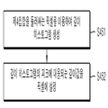
또한, 상기 집합에 포함된 상기 색상 영상의 지점에 깊이값을 설정하는 단계는, 상기 제4집합에 포함된 각각의 제12픽셀에 대하여, 상기 제4집합을 둘러싸고 상기 깊이값이 설정된 적어도 하나 이상의 제13픽셀의 상기 깊이값 및 상기 제12픽셀과 상기 제13픽셀의 위치 차이를 이용하여 깊이 히스토그램이 생성되는 단계를 포함할 수 있다.In addition, the step of setting a depth value at a point of the color image included in the set may include, for each of the twelfth pixels included in the fourth set, at least one or more pixels surrounding the fourth set, And generating the depth histogram using the depth value of the thirteenth pixel and the positional difference between the twelfth pixel and the thirteenth pixel.
또한, 상기 깊이 히스토그램이 생성되는 단계 이후에, 상기 깊이 히스토그램의 피크(peak)에 대응되는 상기 깊이값이 상기 제12픽셀의 깊이값으로서 설정되는 단계를 더 포함할 수 있다.The depth value corresponding to a peak of the depth histogram may be set as a depth value of the twelfth pixel after the step of generating the depth histogram.
또한, 상기 깊이 히스토그램이 생성되는 단계 이후에, 상기 제12픽셀과 인접한 픽셀과 상기 제12픽셀의 색상 차이를 기초로 한 가중치 및 상기 깊이 히스토그램을 이용하여 모델링된 마르코프 무작위 필드(Markov Random Field) 점수를 최대화하는 깊이값이 상기 제12픽셀의 깊이값으로서 설정되는 단계를 더 포함할 수 있다.In addition, after the step of generating the depth histogram, a weight based on a color difference between the pixel adjacent to the twelfth pixel and the twelfth pixel, and a Markov Random Field score modeled using the depth histogram May be set as a depth value of the twelfth pixel.
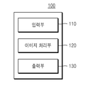
본 발명의 실시예에 따른 영상 처리 장치는, 특정한 장면(scene)에 대한 깊이 맵 또는 색상 영상을 수신하거나 생성하는 입력부, 상기 깊이 맵에 포함된 각각의 지점을 상기 색상 영상에 투영하고, 상기 깊이 맵이 투영된 상기 색상 영상을 적어도 둘 이상의 영상 분할 방법을 이용하여 각각의 분할된 결과를 생성하고, 상기 각각의 분할된 결과에 따라 상기 색상 영상에 포함된 지점들을 적어도 하나 이상의 집합으로 분류하고, 상기 집합에 포함된 상기 색상 영상의 지점에 깊이값을 설정하는 이미지 처리부, 및 상기 깊이값이 설정된 상기 색상 영상을 출력하는 출력부를 포함할 수 있다.An image processing apparatus according to an embodiment of the present invention includes an input unit for receiving or generating a depth map or a color image for a specific scene, a projection unit for projecting each point included in the depth map on the color image, A method of generating a color image in which a map is projected, the method comprising the steps of: generating each divided result using at least two or more image segmentation methods; classifying points included in the color image into at least one set according to each divided result; An image processing unit for setting a depth value at a point of the color image included in the set, and an output unit for outputting the color image with the depth value set.
본 발명의 실시예에 따르면 깊이 맵의 해상도보다 더 높은 해상도를 갖는 색상 영상을 이용하여 상기 깊이 맵의 해상도를 상기 색상 영상의 해상도로 업샘플링할 수 있다.According to an embodiment of the present invention, the resolution of the depth map can be upsampled to the resolution of the color image using a color image having a higher resolution than the resolution of the depth map.
본 발명의 실시예에 따르면 대상에 대한 깊이 맵에서의 경계가 대상에 대한 색상 영상에서의 경계와 일치하도록 상기 깊이 맵을 업샘플링할 수 있다.According to an embodiment of the present invention, the depth map can be upsampled such that the boundary in the depth map for the object coincides with the boundary in the color image for the object.
본 발명의 실시예에 따르면 깊이 맵의 해상도를 상기 해상도보다 더 높은 해상도로 업샘플링할 수 있다.According to the embodiment of the present invention, the resolution of the depth map can be upsampled to a resolution higher than the resolution.
본 발명의 실시예에 따르면 시점의 위치 및 방향이 유사한 깊이 센서 및 색상 카메라를 통해 각각 수신된 깊이 맵 및 색상 영상을 이용하여, 상기 색상 영상의 시점 및 해상도와 동일한 시점 및 해상도를 갖는 깊이 맵을 생성할 수 있다.According to the embodiment of the present invention, a depth map having the same viewpoint and resolution as the viewpoint and resolution of the color image using the depth map and the color image respectively received through the depth sensor and the color camera, Can be generated.
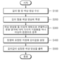
도 1은 본 발명의 실시예에 따른 영상 처리 방법이 수행되는 순서를 나타낸 순서도이다.
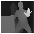
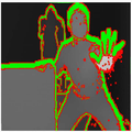
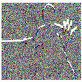
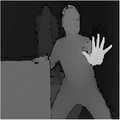
도 2는 본 발명의 실시예에 따라 수신된 깊이 맵을 시각적으로 도시화한 도면이다.
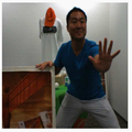
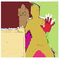
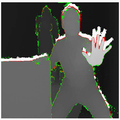
도 3은 본 발명의 실시예에 따라 수신된 색상 영상을 나타낸 도면이다.
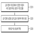
도 4는 본 발명의 실시예에 따라 깊이 맵이 색상 영상에 투영되는 순서를 나타낸 순서도이다.
도 5는 본 발명의 실시예에 따라 깊이 맵의 지점 중에서 인접한 지점과 서로 불연속하는 불연속 지점이 검출되는 순서를 나타낸 순서도이다.
도 6은 본 발명의 실시예에 따라 주변 지점의 벡터를 이용하여 특정한 지점의 예상 깊이값이 계산되는 과정을 설명하기 위한 참고도이다.
도 7은 본 발명의 실시예에 따라 깊이 맵의 지점 중에서 인접한 지점과 서로 불연속하는 불연속 지점이 검출된 결과를 나타낸 개념도이다.
도 8은 본 발명의 실시예에 따라 깊이 맵의 지점 중에서 인접한 지점과 서로 불연속하는 불연속 지점이 검출된 결과를 시각적으로 나타낸 도면이다.
도 9는 본 발명의 실시예에 따라 메쉬가 생성되는 순서를 나타낸 순서도이다.
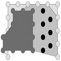
도 10은 본 발명의 실시예에 따라 메쉬가 생성된 결과를 나타낸 개념도이다.
도 11은 본 발명의 실시예에 따라 메쉬가 색상 영상에 투영된 결과를 나타낸 개념도이다.
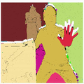
도 12는 본 발명의 실시예에 따라 메쉬가 색상 영상에 투영된 결과를 시각적으로 나타낸 도면이다.
도 13은 본 발명의 실시예에 따라 색상 영상이 둘 이상의 방법으로 분할되고 분할 결과에 따라 각각의 지점들이 하나 이상의 집합으로 분류되는 순서를 나타낸 순서도이다.
도 14는 본 발명의 실시예에 따라 메쉬의 각각의 정점의 깊이값을 이용하여 메쉬에 포함된 각각의 지점에 깊이값이 설정되는 순서를 나타낸 순서도이다.
도 15는 본 발명의 실시예에 따라 메쉬에 포함된 각각의 지점에 깊이값이 설정된 결과를 나타낸 개념도이다.
도 16은 본 발명의 실시예에 따라 불연속 영역이 검출된 결과를 나타낸 개념도이다.
도 17은 본 발명의 실시예에 따라 홀 영역이 검출된 결과를 나타낸 개념도이다.
도 18은 본 발명의 실시예에 따라 불연속 영역 및 홀 영역이 검출된 결과를 시각적으로 나타낸 도면이다.
도 19는 본 발명의 실시예에 따라 홀 영역 내부에 가상 정점이 생성된 결과를 나타낸 개념도이다.
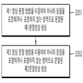
도 20은 본 발명의 실시예에 따라 둘 이상의 영상 분할 방법을 이용하여 색상 영상이 분할되는 순서를 나타내는 순서도이다.
도 21은 본 발명의 실시예에 따라 제1 영상 분할 방법을 이용하여 색상 영상이 분할된 결과를 시각적으로 나타낸 도면이다.
도 22는 본 발명의 실시예에 따라 제2 영상 분할 방법을 이용하여 색상 영상이 분할된 결과를 시각적으로 나타낸 도면이다.
도 23은 본 발명의 실시예에 따라 색상 영상의 각각의 지점들을 하나 이상의 집합으로 분류하는 순서를 나타내는 순서도이다.
도 24는 본 발명의 실시예에 따라 깊이 맵이 분할된 분할영상을 시각적으로 나타낸 도면이다.
도 25는 본 발명의 실시예에 따라 제1 영상 분할 방법을 이용하여 분할된 각각의 영역에 레이블이 설정된 결과를 시각적으로 나타낸 도면이다.
도 26은 본 발명의 실시예에 따라 제2 영상 분할 방법을 이용하여 분할된 각각의 영역에 레이블이 설정된 결과를 시각적으로 나타낸 도면이다.
도 27은 본 발명의 실시예에 따라 색상 영상의 각각의 지점들이 하나 이상의 집합으로 분류된 결과를 시각적으로 나타낸 도면이다.
도 28은 본 발명의 실시예에 따라 집합에 포함된 지점에 깊이값을 설정하는 순서를 나타내는 순서도이다.
도 29는 본 발명의 실시예에 따라 제1집합의 픽셀에 대해 깊이 히스토그램이 생성되고 깊이값이 픽셀에 설정되는 순서를 나타내는 순서도이다.
도 30은 본 발명의 실시예에 따라 제2집합의 픽셀이 서브집합으로 분할된 결과를 나타낸 개념도이다.
도 31은 본 발명의 실시예에 따라 제2집합의 픽셀에 깊이값이 설정된 결과를 시각적으로 나타낸 도면이다.
도 32는 본 발명의 실시예에 따라 제3집합의 픽셀에 대해 깊이 히스토그램이 생성되고 깊이값이 픽셀에 설정되는 순서를 나타내는 순서도이다.
도 33은 본 발명의 다른 실시예에 따라 제3집합의 픽셀에 대해 깊이 히스토그램이 생성되고 깊이값이 픽셀에 설정되는 순서를 나타내는 순서도이다.
도 34는 본 발명의 실시예에 따라 제4집합의 픽셀에 대해 깊이 히스토그램이 생성되고 깊이값이 픽셀에 설정되는 순서를 나타내는 순서도이다.
도 35는 본 발명의 실시예에 따라 제4집합을 둘러싸는 픽셀을 이용하여 깊이 히스토그램이 생성되는 과정을 설명하기 위한 참고도이다.
도 36은 본 발명의 다른 실시예에 따라 제4집합의 픽셀에 대해 깊이 히스토그램이 생성되고 깊이값이 픽셀에 설정되는 순서를 나타내는 순서도이다.
도 37은 본 발명의 실시예에 따라 깊이값이 설정된 색상 영상이 출력된 결과를 시각적으로 나타낸 도면이다.
도 38은 본 발명의 실시예에 따른 영상 처리 장치의 구성을 나타내는 블록도이다.FIG. 1 is a flowchart illustrating a procedure in which an image processing method according to an exemplary embodiment of the present invention is performed.
2 is a graphical representation of a received depth map according to an embodiment of the present invention.
3 is a diagram illustrating a received color image according to an embodiment of the present invention.
FIG. 4 is a flowchart illustrating a procedure in which a depth map is projected onto a color image according to an embodiment of the present invention.
FIG. 5 is a flowchart showing a sequence of detecting discontinuous points that are discontinuous with adjacent points among the points of the depth map according to the embodiment of the present invention.
FIG. 6 is a reference diagram for explaining a process of calculating a predicted depth value at a specific point using a vector of a surrounding point according to an embodiment of the present invention.
FIG. 7 is a conceptual diagram showing a result of detecting discontinuous points that are discontinuous with adjacent points among the points of the depth map according to the embodiment of the present invention. FIG.
FIG. 8 is a diagram showing a result of detecting discontinuous points that are discontinuous with adjacent points among the points of the depth map according to the embodiment of the present invention. FIG.
FIG. 9 is a flowchart illustrating a sequence in which meshes are generated according to an embodiment of the present invention.
10 is a conceptual diagram illustrating a result of generating a mesh according to an embodiment of the present invention.
11 is a conceptual diagram illustrating a result of projection of a mesh onto a color image according to an embodiment of the present invention.
12 is a diagram showing a result of a projection of a mesh onto a color image according to an embodiment of the present invention.
13 is a flowchart illustrating a procedure in which a color image is divided into two or more methods according to an embodiment of the present invention, and each point is classified into one or more sets according to the division result.
FIG. 14 is a flowchart illustrating a procedure of setting depth values at respective points included in a mesh using depth values of respective vertices of a mesh according to an embodiment of the present invention. FIG.
15 is a conceptual diagram illustrating a result of setting depth values at respective points included in a mesh according to an embodiment of the present invention.
16 is a conceptual diagram showing a result of detecting a discontinuous area according to an embodiment of the present invention.
17 is a conceptual diagram showing a result of detection of a hole region according to an embodiment of the present invention.
18 is a diagram showing a result of detecting a discontinuous area and a hole area according to an embodiment of the present invention.
19 is a conceptual diagram showing a result of generating a virtual vertex in a hole region according to an embodiment of the present invention.
FIG. 20 is a flowchart illustrating a procedure of dividing a color image using two or more image segmentation methods according to an embodiment of the present invention.
FIG. 21 is a diagram showing a result of dividing a color image using a first image segmentation method according to an embodiment of the present invention.
22 is a diagram showing a result of dividing a color image using a second image segmentation method according to an embodiment of the present invention.
23 is a flowchart showing a procedure of sorting each point of a color image into one or more sets according to an embodiment of the present invention.
FIG. 24 is a diagram showing a divided image obtained by dividing a depth map according to an embodiment of the present invention. FIG.
FIG. 25 is a diagram visually showing a result of setting a label in each divided area using the first image segmentation method according to an embodiment of the present invention. FIG.
FIG. 26 is a diagram showing a result of setting a label in each of divided areas using the second image segmentation method according to an embodiment of the present invention. FIG.
FIG. 27 is a diagram showing a result of visualizing each of the points of a color image classified into one or more sets according to an embodiment of the present invention.
28 is a flowchart showing a procedure of setting a depth value at a point included in the set according to an embodiment of the present invention.
29 is a flowchart showing a sequence in which a depth histogram is generated for a first set of pixels and depth values are set in pixels according to an embodiment of the present invention.
30 is a conceptual diagram illustrating a result of dividing a second set of pixels into subsets according to an embodiment of the present invention.
31 is a diagram showing a result of visually showing a result of setting a depth value in a second set of pixels according to an embodiment of the present invention.
32 is a flowchart showing a sequence in which a depth histogram is generated for a third set of pixels and depth values are set in pixels according to an embodiment of the present invention.
33 is a flowchart illustrating a procedure in which a depth histogram is generated for a third set of pixels and a depth value is set for pixels according to another embodiment of the present invention.
FIG. 34 is a flowchart showing a sequence in which a depth histogram is generated for a fourth set of pixels and depth values are set in pixels according to an embodiment of the present invention. FIG.
35 is a reference diagram for explaining a process of generating a depth histogram using pixels surrounding a fourth set according to an embodiment of the present invention.
FIG. 36 is a flowchart showing a sequence in which a depth histogram is generated for a fourth set of pixels and depth values are set in pixels according to another embodiment of the present invention. FIG.
FIG. 37 is a diagram showing a result of outputting a color image in which a depth value is set according to an embodiment of the present invention.
38 is a block diagram showing a configuration of an image processing apparatus according to an embodiment of the present invention.
본 발명의 이점 및 특징, 그리고 그것들을 달성하는 방법은 첨부되는 도면과 함께 상세하게 후술되어 있는 실시예들을 참조하면 명확해질 것이다. 그러나 본 발명은 이하에서 개시되는 실시예들에 한정되는 것이 아니라 서로 다른 다양한 형태로 구현될 것이며, 단지 본 실시예들은 본 발명의 개시가 완전하도록 하며, 본 발명이 속하는 기술분야에서 통상의 지식을 가진 자에게 발명의 범주를 완전하게 알려주기 위해 제공되는 것이며, 본 발명은 청구항의 범주에 의해 정의될 뿐이다. 명세서 전체에 걸쳐 동일 참조 부호는 동일 구성 요소를 지칭한다.BRIEF DESCRIPTION OF THE DRAWINGS The advantages and features of the present invention and the manner of achieving them will become apparent with reference to the embodiments described in detail below with reference to the accompanying drawings. The present invention may, however, be embodied in many different forms and should not be construed as being limited to the embodiments set forth herein. Rather, these embodiments are provided so that this disclosure will be thorough and complete, and will fully convey the scope of the invention to those skilled in the art. Is provided to fully convey the scope of the invention to those skilled in the art, and the invention is only defined by the scope of the claims. Like reference numerals refer to like elements throughout the specification.
비록 "제1" 또는 "제2" 등이 다양한 구성요소를 서술하기 위해서 사용되나, 이러한 구성요소는 상기와 같은 용어에 의해 제한되지 않는다. 상기와 같은 용어는 단지 하나의 구성요소를 다른 구성요소와 구별하기 위하여 사용될 수 있다. 따라서, 이하에서 언급되는 제1구성요소는 본 발명의 기술적 사상 내에서 제2구성요소일 수도 있다.Although "first" or "second" and the like are used to describe various components, such components are not limited by such terms. Such terms may be used to distinguish one element from another. Therefore, the first component mentioned below may be the second component within the technical spirit of the present invention.
본 명세서에서 사용된 용어는 실시예를 설명하기 위한 것이며 본 발명을 제한하고자 하는 것은 아니다. 본 명세서에서, 단수형은 문구에서 특별히 언급하지 않는 한 복수형도 포함한다. 명세서에서 사용되는 "포함한다(comprises)" 또는 "포함하는(comprising)"은 언급된 구성요소 또는 단계가 하나 이상의 다른 구성요소 또는 단계의 존재 또는 추가를 배제하지 않는다는 의미를 내포한다.The terminology used herein is for the purpose of illustrating embodiments and is not intended to be limiting of the invention. In the present specification, the singular form includes plural forms unless otherwise specified in the specification. &Quot; comprises "or" comprising "as used herein mean that the stated element or step does not exclude the presence or addition of one or more other elements or steps.
다른 정의가 없다면, 본 명세서에서 사용되는 모든 용어는 본 발명이 속하는 기술분야에서 통상의 지식을 가진 자에게 공통적으로 이해될 수 있는 의미로 해석될 수 있다. 또한, 일반적으로 사용되는 사전에 정의되어 있는 용어들은 명백하게 특별히 정의되어 있지 않는 한 이상적으로 또는 과도하게 해석되지 않는다.Unless defined otherwise, all terms used herein are to be construed in a sense that is commonly understood by one of ordinary skill in the art to which this invention belongs. In addition, commonly used predefined terms are not ideally or excessively interpreted unless explicitly defined otherwise.
이하에서는, 도 1 내지 도 38을 참조하여 본 발명의 실시예에 따른 영상 처리 방법 및 영상 처리 장치(100)에 대해 상세히 설명하기로 한다.Hereinafter, an image processing method and an
도 1은 본 발명의 실시예에 따른 영상 처리 방법이 수행되는 순서를 나타낸 순서도이다. 도 1을 참조하면 본 발명의 실시예에 따른 영상 처리 방법은 먼저, 특정한 장면(scene)에 대한 깊이 맵(map) 및 색상 영상을 수신하는 단계(S100)가 수행될 수 있다. FIG. 1 is a flowchart illustrating a procedure in which an image processing method according to an exemplary embodiment of the present invention is performed. Referring to FIG. 1, an image processing method according to an exemplary embodiment of the present invention may include performing a step S100 of receiving a depth map and a color image for a specific scene.
도 2는 본 발명의 실시예에 따라 수신된 깊이 맵을 시각적으로 도시화한 도면이다. 깊이 맵은 깊이 센서에 의해 생성될 수 있다. 또한, 깊이 맵은 깊이 센서에 의해 감지된 결과가 변환된 결과물일 수 있다. 깊이 센서는 예를 들어, 스테레오스코픽 카메라(stereoscopic camera), 패턴 프로젝션 카메라(pattern projection camera), TOF(Time Of Flight) 카메라, 또는 유사한 측정 장치 중에서 어느 하나일 수 있다.2 is a graphical representation of a received depth map according to an embodiment of the present invention. The depth map can be generated by a depth sensor. Also, the depth map may be the result of transforming the sensed result by the depth sensor. The depth sensor can be, for example, any of a stereoscopic camera, a pattern projection camera, a TOF (Time Of Flight) camera, or a similar measuring device.
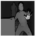
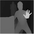
도 3은 본 발명의 실시예에 따라 수신된 색상 영상을 나타낸 도면이다. 색상 영상은 광학 촬영 장치에 의해 생성될 수 있다. 또한, 색상 영상은 광학 촬영 장치에 의해 촬영된 결과가 변환된 결과물일 수 있다. 광학 촬영 장치는 예를 들어, CMOS 카메라, CCD 카메라(Charge-Coupled Device camera), 또는 유사한 촬영 장치 중에서 어느 하나일 수 있다.3 is a diagram illustrating a received color image according to an embodiment of the present invention. The color image can be generated by the optical photographing apparatus. In addition, the color image may be the result of conversion of the result of photographing by the optical photographing apparatus. The optical photographing apparatus may be, for example, a CMOS camera, a CCD camera (Charge-Coupled Device camera), or a similar photographing apparatus.
본 발명의 실시예에 따르면 상기 깊이 맵 및 색상 영상은 시점의 위치 및 방향이 유사한 깊이 센서 및 색상 카메라를 통해 각각 수신될 수 있다. 또한, 색상 영상의 해상도는 깊이 맵의 해상도보다 더 높을 수 있다.According to the embodiment of the present invention, the depth map and the color image can be respectively received through the depth sensor and the color camera having the same position and direction of the viewpoint. Also, the resolution of the color image may be higher than the resolution of the depth map.
다시 도 1을 참조하면, 다음으로, 상기 깊이 맵에 포함된 각각의 지점을 상기 색상 영상에 투영하는 단계(S200)가 수행될 수 있다. 도 4는 본 발명의 실시예에 따라 깊이 맵이 색상 영상에 투영되는 순서를 나타낸 순서도이다. Referring again to FIG. 1, a step S200 of projecting each point included in the depth map on the color image may be performed. FIG. 4 is a flowchart illustrating a procedure in which a depth map is projected onto a color image according to an embodiment of the present invention.
도 4를 참조하면, 깊이 맵이 색상 영상에 투영되는 단계(S200)는 먼저, 상기 깊이 맵의 각각의 제1지점의 깊이값 및 상기 제1지점과 서로 인접한 제2지점의 깊이값을 이용하여, 상기 제1지점 중에서 상기 제2지점과 서로 불연속하는 불연속 지점을 검출하는 단계(S210)가 수행될 수 있다. 도 5는 본 발명의 실시예에 따라 깊이 맵의 지점 중에서 인접한 지점과 서로 불연속하는 불연속 지점이 검출되는 순서를 나타낸 순서도이다.Referring to FIG. 4, in step S200, a depth map is projected onto a color image using a depth value of each first point of the depth map and a depth value of a second point adjacent to the first point, , A step S210 of detecting a discontinuous point that is discontinuous with the second point among the first points may be performed. FIG. 5 is a flowchart showing a sequence of detecting discontinuous points that are discontinuous with adjacent points among the points of the depth map according to the embodiment of the present invention.
도 5를 참조하면, 깊이 맵의 지점 중에서 인접한 지점과 서로 불연속하는 불연속 지점이 검출되는 단계(S210)는 먼저, 상기 깊이 맵의 각각의 제1지점에 대해 상기 제1지점의 접평면에 대응되는 벡터를 산출하는 단계(S211)가 수행될 수 있다.Referring to FIG. 5, a step S210 of detecting a discontinuity point that is discontinuous with an adjacent point among the points of the depth map is performed by first obtaining, for each first point of the depth map, a vector corresponding to a tangent plane of the first point (S211) may be performed.
본 발명의 실시예에 따르면 미리 정해진 문턱값을 이용하여 깊이 맵에서 서로 인접한 제1지점들 사이의 불연속성(discontinuity) 여부가 판정될 수 있다. 만약 대상의 연속된 표면의 법선 방향과 깊이 센서의 시각 방향(viewing direction)이 특정한 기준 각도보다 큰 각도를 이룬다고 가정하면, 서로 인접한 제1지점들 각각의 깊이값의 상기 문턱값보다 클 수 있다. 따라서, 실제로는 대상의 표면이 연속성을 가짐에도 불구하고 불연속성을 가진다고 판정될 수 있다. 따라서 본 발명의 실시예에서와 같이 제1지접의 접평면에 대응되는 벡터를 산출하고 이를 이용하는 경우, 대상의 표면의 법선 방향에 대한 요소가 고려되므로 상기와 같은 오류가 방지될 수 있다.According to an embodiment of the present invention, it is possible to determine whether discontinuity between first points adjacent to each other in the depth map is determined using a predetermined threshold value. If it is assumed that the normal direction of the continuous surface of the object and the viewing direction of the depth sensor are at an angle greater than a certain reference angle, then it may be greater than the threshold value of the depth value of each of the adjacent first points . Thus, in practice, it can be determined that the surface of the object has discontinuity even though it has continuity. Therefore, as in the embodiment of the present invention, when a vector corresponding to the tangential plane of the first fingernail is calculated and used, the above-mentioned error can be prevented because the element for the normal direction of the surface of the object is considered.
본 발명의 실시예에 따르면, 어느 하나의 제1지점을 중심으로 하는 3 * 3 크기의 영역에 포함된 각각의 지점의 깊이값을 이용하여 상기 제1지점의 접평면에 대응되는 벡터가 산출될 수 있다. 예를 들어, 제1지점 u의 깊이값 du는 다음의 수학식 1과 같이 표현될 수 있다.According to the embodiment of the present invention, a vector corresponding to the tangential plane of the first point can be calculated using the depth value of each point included in the 3 * 3 region centered on any one first point have. For example, the depth value du of the first point u can be expressed by the following equation (1).

따라서, 본 발명의 실시예에 따르면 상기 3 * 3 크기의 영역에 포함된 각각의 지점의 위치 벡터 (x, y) 및 각각의 지점의 깊이값을 이용하여 상기 수학식 1을 만족시키는 벡터 ![]()
![]()
다음으로, 상기 각각의 제1지점에 대해 상기 제1지점을 중심으로 한 특정한 범위의 영역 내에 포함된 적어도 하나 이상의 제3지점의 상기 벡터를 이용하여 계산된 상기 제1지점의 예상 깊이값과 상기 깊이 맵에 포함된 상기 제1지점의 깊이값의 차이 중에서 최소값을 산출하는 단계(S212)가 수행될 수 있다. 도 6은 본 발명의 실시예에 따라 주변 지점의 벡터를 이용하여 특정한 지점의 예상 깊이값이 계산되는 과정을 설명하기 위한 참고도이다.Next, an estimated depth value of the first point calculated using the vector of at least one third point included in a specific range of the area about the first point with respect to each of the first points, The step S212 of calculating the minimum value among the differences of the depth values of the first point included in the depth map may be performed. FIG. 6 is a reference diagram for explaining a process of calculating a predicted depth value at a specific point using a vector of a surrounding point according to an embodiment of the present invention.
도 6에 나타난 바와 같이, 제1지점을 중심으로 한 3 * 3의 크기의 영역 내에 포함된 각각의 지점에 대해 앞서 산출된 벡터를 이용하여 상기 제1지점의 예상 깊이값이 산출될 수 있다. 다시 말해서, 상기 영역 내에 포함된 지점 중에서 상기 제1지점을 제외한 8개의 제3지점 각각을 이용하여 상기 제1지점에 대한 8개의 예상 깊이값이 산출될 수 있다. 예상 깊이값은 상기 제1지점의 위치에 대응하는 벡터와 상기 제3지점에 대해 앞서 산출된 벡터를 내적함으로써 산출될 수 있다.As shown in FIG. 6, the predicted depth value of the first point can be calculated using the previously calculated vector for each point included in the area of the 3 * 3 size centered on the first point. In other words, eight predicted depth values for the first point can be calculated using each of the eight third points except for the first point among the points included in the area. The expected depth value can be calculated by discarding the vector corresponding to the position of the first point and the previously calculated vector for the third point.
또한, 상기 산출된 예상 깊이값과 상기 깊이 맵에 포함된 상기 제1지점의 실제 깊이값의 차이가 산출될 수 있다. 도 6을 참조하면 총 8의 예상 깊이값이 산출될 수 있으므로 총 8개의 차이값이 산출될 수 있다. 또한, 상기 산출된 차이값 중에서 최소값이 산출될 수 있다. 상기와 같은 과정을 상기 깊이 맵에 포함된 모든 지점에 대하여 반복하면 상기 각각의 지점에 대해 상기 최소값이 하나씩 산출될 수 있다.The difference between the calculated expected depth value and the actual depth value of the first point included in the depth map can be calculated. Referring to FIG. 6, since a total of 8 estimated depth values can be calculated, a total of 8 difference values can be calculated. Also, the minimum value among the calculated difference values may be calculated. If the above process is repeated for all points included in the depth map, the minimum value may be calculated for each point.
상술한 바에 따르면, 제1지점 u에 대응되는 상기 최소값 lu는 다음의 수학식 2와 같이 표현될 수 있다.According to the above description, the minimum value lu corresponding to the first point u can be expressed by the following equation (2).

상기 수학식 2에서 Nu는 상기 제1지점 u를 중심으로 한 특정한 크기의 영역 내에 포함된 제3지점 u'을 포함하는 집합이다. 상기 수학식 2에서 벡터 u는 상기 제1지점 u의 위치 벡터이다. 또한, 상기 수학식 2에서 du는 깊이맵에 포함된 상기 제1지점 u의 깊이값이다. 또한, lu'은 제3지점 u'의 접평면에 대응되는 벡터이다.In Equation (2), Nu is a set including a third point u 'included in a region of a specific size centered on the first point u. In Equation (2), u is a position vector of the first point u. In Equation (2), du is the depth value of the first point u included in the depth map. Also, lu 'is a vector corresponding to the tangent plane of the third point u'.
다음으로, 상기 제1지점의 깊이값, 상기 제2지점의 깊이값, 상기 제1지점의 상기 최소값 및 상기 제2지점의 상기 최소값을 이용하여 상기 제1지점 중에서 상기 제2지점과 서로 불연속하는 불연속 지점을 검출하는 단계(S213)가 수행될 수 있다. Next, using the depth value of the first point, the depth value of the second point, the minimum value of the first point and the minimum value of the second point, A step S213 of detecting a discontinuity point may be performed.
예를 들어, 상기 제1지점의 깊이값과 상기 제2지점의 깊이값의 차이가 작을수록 상기 제1지점과 상기 제2지점은 연속성을 가질 확률이 더 높을 수 있다. 따라서, 상기 제1지점의 깊이값과 상기 제2지점의 깊이값의 차이를 상기 문턱값과 비교함으로써 불연속성 여부가 판정될 수 있다.For example, the smaller the difference between the depth value of the first point and the depth value of the second point, the higher the probability that the first point and the second point have continuity. Therefore, the discontinuity can be determined by comparing the difference between the depth value of the first point and the depth value of the second point with the threshold value.
또한, 상기 장면 내에 존재하는 적어도 하나 이상의 객체 중에서 상기 제1지점에 대응되는 제1객체와 상기 제2지점에 대응되는 제2객체가 서로 동일한지 여부에 대한 판정결과에 따라 불연속성이 판단될 수 있다. 상기 제1객체와 상기 제2객체가 서로 동일한지 여부에 대한 판정은 다음과 같이 수행될 수 있다. The discontinuity may be determined according to a determination result as to whether or not a first object corresponding to the first point and a second object corresponding to the second point are the same among at least one object existing in the scene . The determination as to whether the first object and the second object are equal to each other can be performed as follows.
제2지점의 접평면에 대응되는 벡터를 이용하여 계산된 상기 제1지점의 예상 깊이값과 깊이 맵에 포함된 상기 제1지점의 실제 깊이값의 차이가 작을수록 연속성을 가질 확률이 더 높을 수 있다. 또한, 상기 제1지점의 접평면에 대응되는 벡터를 이용하여 계산된 상기 제2지점의 예상 깊이값과 깊이 맵에 포함된 상기 제2지점의 실제 깊이값의 차이가 작을수록 연속성을 가질 확률이 더 높을 수 있다. The smaller the difference between the estimated depth value of the first point and the actual depth value of the first point included in the depth map calculated using the vector corresponding to the tangent plane of the second point, the higher the probability of having continuity . The smaller the difference between the estimated depth value of the second point calculated using the vector corresponding to the tangent plane of the first point and the actual depth value of the second point included in the depth map, Can be high.
따라서, 상기 차이값과 문턱값을 비교함으로써 불연속성 여부가 판정될 수 있다. 상기 제1지점 또는 상기 제2지점의 예상 깊이값은 상기 제1지점 또는 상기 제2지점의 위치에 대응하는 벡터와 상기 제2지점 또는 상기 제1지점에 대해 앞서 산출된 최소값을 내적함으로써 산출될 수 있다.Therefore, the discontinuity can be determined by comparing the difference value with the threshold value. The predicted depth value of the first point or the second point is calculated by deducing a vector corresponding to the position of the first point or the second point and a minimum value calculated previously for the second point or the first point .
상술한 바에 따르면, 제1지점 u와 상기 제1지점 u에 인접하는 제2지점 u' 사이의 불연속성 여부를 판정하기 위해 다음의 수학식 3에 나타난 바와 같은 불연속 지수 e가 산출될 수 있다. 또한, 상기 불연속 지수 e와 미리 정의된 문턱값을 비교하여 상기 불연속 지수 e가 상기 문턱값보다 크거나 같은 경우, 제1지점 u와 제2지점 u'는 불연속성을 갖는 것으로 판정될 수 있다.According to the above description, a discontinuity index e as shown in the following equation (3) can be calculated to determine whether there is discontinuity between the first point u and the second point u 'adjacent to the first point u. Also, when the discontinuity index e is compared with a predefined threshold value, if the discontinuity index e is greater than or equal to the threshold value, the first point u and the second point u 'may be determined to have discontinuities.

상기 수학식 3에서, du는 제1지점 u의 깊이값이고, du'은 제2지점 u'의 깊이값이다. 벡터 u는 제1지점 u의 위치 벡터이고 벡터 u'은 제2지점 u'의 위치 벡터이다. 벡터 lu'은 제2지점 u'에 대해 앞서 산출된 최소값이고, 벡터 lu는 제1지점 u에 대해 앞서 산출된 최소값이다.In Equation (3), du is the depth value of the first point u and du 'is the depth value of the second point u'. The vector u is the position vector of the first point u and the vector u 'is the position vector of the second point u'. The vector lu 'is the minimum value calculated previously for the second point u', and the vector lu is the minimum value calculated for the first point u.
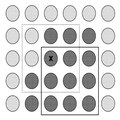
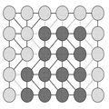
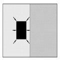
도 7은 본 발명의 실시예에 따라 깊이 맵의 지점 중에서 인접한 지점과 서로 불연속하는 불연속 지점이 검출된 결과를 나타낸 개념도이다. 도 7을 참조하면 인접한 두 지점이 불연속성을 가지는 경우 상기 두 지점을 잇는 간선(edge)은 점선으로 표현되어 있다. 또한, 인접한 두 지점이 연속성을 가지는 경우 상기 두 지점을 잇는 간선은 실선으로 표현되어 있다. 도 7을 참조하면, 검정색 지점으로 구성된 부분은 회색 지점으로 구성된 부분과 불연속성을 가질 수 있다. 따라서, 검정색 지점으로 구성된 부분과 회색 지점으로 구성된 부분은 서로 다른 객체일 수 있다.FIG. 7 is a conceptual diagram showing a result of detecting discontinuous points that are discontinuous with adjacent points among the points of the depth map according to the embodiment of the present invention. FIG. Referring to FIG. 7, when two neighboring points have discontinuities, an edge connecting the two points is represented by a dotted line. In addition, when two adjacent points have continuity, the trunk connecting the two points is represented by a solid line. Referring to FIG. 7, a portion constituted by black points may have a discontinuity with a portion constituted by gray points. Therefore, the portion composed of black points and the portion composed of gray points may be different objects.
도 8은 본 발명의 실시예에 따라 깊이 맵의 지점 중에서 인접한 지점과 서로 불연속하는 불연속 지점이 검출된 결과를 시각적으로 나타낸 도면이다. 도 8을 참조하면, 불연속 지점의 집합은 장면에 포함된 객체의 경계를 나타낼 수 있다.FIG. 8 is a diagram showing a result of detecting discontinuous points that are discontinuous with adjacent points among the points of the depth map according to the embodiment of the present invention. FIG. Referring to FIG. 8, a set of discontinuous points may represent a boundary of an object included in a scene.
다시 도 4를 참조하면, 다음으로, 상기 제1지점의 깊이값과 상기 제2지점의 깊이값의 차이 및 상기 제1지점을 이용하여 메쉬를 생성하는 단계(S220)가 수행될 수 있다. 도 9는 본 발명의 실시예에 따라 메쉬가 생성되는 순서를 나타낸 순서도이다.Referring again to FIG. 4, a difference between the depth value of the first point and the depth value of the second point, and generating the mesh using the first point may be performed (S220). FIG. 9 is a flowchart illustrating a sequence in which meshes are generated according to an embodiment of the present invention.
도 9를 참조하면, 메쉬가 생성되는 단계(S220)는 먼저, 상기 제1지점과 가로 방향으로 서로 인접한 제4지점을 상기 제1지점과 연결하는 단계(S221)가 수행될 수 있다. 다음으로, 상기 제1지점과 세로 방향으로 서로 인접한 상기 제5지점을 상기 제1지점과 연결하는 단계(S222)가 수행될 수 있다. Referring to FIG. 9, a step S220 of creating a mesh may be performed by connecting a first point and a fourth point adjacent to each other in the horizontal direction (S221) with the first point. Next, connecting the first point and the fifth point adjacent to each other in the longitudinal direction with the first point (S222) may be performed.
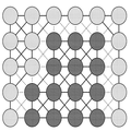
다음으로, 상기 제4지점의 깊이값과 상기 제5지점의 깊이값의 차이 및 상기 제4지점과 세로 방향으로 인접하고 상기 제5지점과 가로 방향으로 인접하는 제6지점의 깊이값과 상기 제1지점의 깊이값의 차이 중에서 더 작은 쪽에 대응되는 상기 지점들을 서로 연결하는 단계(S223)가 수행될 수 있다. 다시 말해서, 사각형을 이루는 네 개의 지점이 대각선 방향에 따라 두 개씩 나뉠 수 있다. 상기 두쌍의 지점들 중에서, 지점에 대응되는 깊이값의 차이가 더 작은 쌍이 서로 연결되고 나머지 한 쌍은 연결되지 않을 수 있다. 도 10은 본 발명의 실시예에 따라 메쉬가 생성된 결과를 나타낸 개념도이다.Next, the difference between the depth value of the fourth point and the depth value of the fifth point and the depth value of the sixth point adjacent to the fourth point in the longitudinal direction and adjacent to the fifth point in the width direction, The step of connecting the points corresponding to the smaller one among the differences of the depth values of the one point (S223) may be performed. In other words, the four points that make up the rectangle can be divided into two in the diagonal direction. Among the two pairs of points, the pair of smaller difference in depth value corresponding to the point may be connected to each other and the other pair may not be connected. 10 is a conceptual diagram illustrating a result of generating a mesh according to an embodiment of the present invention.
다시 도 4를 참조하면, 상기 메쉬를 상기 색상 영상에 투영하는 단계(S230)가 수행될 수 있다. 깊이 센서와 색상 카메라는 미리 서로 캘리브레이션(calibration)되어 있을 수 있다. 다시 말해서, 깊이 센서에 의해 감지된 깊이 맵의 어느 지점이 색상 카메라에 의해 촬영된 색상 영상의 어느 지점에 대응되는지에 대한 매핑 정보가 미리 저장되어 있을 수 있다. 따라서, 상기 매핑 정보를 참조하여, 상기 메쉬가 상기 색상 영상에 투영될 수 있다.Referring again to FIG. 4, the step of projecting the mesh onto the color image (S230) may be performed. The depth sensor and the color camera may be calibrated to each other in advance. In other words, mapping information on which point of the depth map detected by the depth sensor corresponds to which point of the color image photographed by the color camera may be stored in advance. Accordingly, the mesh can be projected onto the color image by referring to the mapping information.
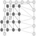
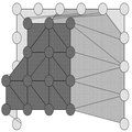
도 11은 본 발명의 실시예에 따라 메쉬가 색상 영상에 투영된 결과를 나타낸 개념도이다. 도 11의 왼쪽 부분에 나타난 바와 같이, 깊이 센서와 색상 카메라의 시점 차이에 의해서 메쉬의 일부 정점들은 서로 겹칠 수 있다. 반대로, 도 11의 오른쪽 부분에 나타난 바와 같이 다른 부분에 비하여 정점의 밀도가 낮은 부분도 존재할 수 있다. 도 12는 본 발명의 실시예에 따라 메쉬가 색상 영상에 투영된 결과를 시각적으로 나타낸 도면이다.11 is a conceptual diagram illustrating a result of projection of a mesh onto a color image according to an embodiment of the present invention. As shown in the left part of FIG. 11, some vertices of the mesh may overlap each other due to the difference in viewpoint between the depth sensor and the color camera. On the contrary, as shown in the right part of FIG. 11, there may be a part where the density of the vertex is lower than other parts. 12 is a diagram showing a result of a projection of a mesh onto a color image according to an embodiment of the present invention.
다시 도 1을 참조하면, 다음으로, 상기 깊이 맵이 투영된 상기 색상 영상을 적어도 둘 이상의 영상 분할 방법을 이용하여 각각의 분할된 결과를 생성하고, 상기 각각의 분할된 결과에 따라 상기 색상 영상에 포함된 지점들을 적어도 하나 이상의 집합으로 분류하는 단계(S300)가 수행될 수 있다. 도 13은 본 발명의 실시예에 따라 색상 영상이 둘 이상의 방법으로 분할되고 분할 결과에 따라 각각의 지점들이 하나 이상의 집합으로 분류되는 순서를 나타낸 순서도이다.Referring again to FIG. 1, the color image, in which the depth map is projected, is generated by using at least two or more image segmentation methods, (S300) of classifying the included points into at least one set may be performed. 13 is a flowchart illustrating a procedure in which a color image is divided into two or more methods according to an embodiment of the present invention, and each point is classified into one or more sets according to the division result.
도 13을 참조하면, 색상 영상에 포함된 지점들이 하나 이상의 집합으로 분류되는 단계(S300)는 먼저, 상기 투영된 메쉬의 각각의 정점의 깊이값을 이용하여 상기 투영된 메쉬에 포함된 각각의 지점에 깊이값을 설정하는 단계(S310)가 수행될 수 있다. 도 14는 본 발명의 실시예에 따라 메쉬의 각각의 정점의 깊이값을 이용하여 메쉬에 포함된 각각의 지점에 깊이값이 설정되는 순서를 나타낸 순서도이다.Referring to FIG. 13, in step S300, points included in a color image are classified into one or more sets. First, a depth value of each vertex of the projected mesh is used to determine the position of each point included in the projected mesh A step S310 of setting a depth value may be performed. FIG. 14 is a flowchart illustrating a procedure of setting depth values at respective points included in a mesh using depth values of respective vertices of a mesh according to an embodiment of the present invention. FIG.
도 14를 참조하면, 메쉬에 포함된 각각의 지점에 깊이값을 설정하는 단계(S310)는 먼저, 상기 각각의 정점의 위치를 기초로 한 평면 방정식을 이용하여 상기 투영된 메쉬에 포함된 각각의 지점에 상기 깊이값을 보간하여 설정하는 단계(S311)가 수행될 수 있다. 각각의 메쉬는 삼각형의 형상을 하고 있을 수 있다. 따라서, 메쉬에 포함된 세 개의 정점(vertex)의 위치 및 깊이값을 기초로 하여 평면 방정식이 산출될 수 있다. 상기 평면 방정식을 이용하여 메쉬의 내부의 각각에 지점에 깊이값이 설정될 수 있다.Referring to FIG. 14, the step of setting a depth value at each point included in the mesh (S310) may be performed by first calculating a depth value of each point included in the projected mesh using a plane equation based on the position of each vertex And interpolating and setting the depth value at a point (S311) may be performed. Each mesh can be in the shape of a triangle. Therefore, a plane equation can be calculated based on the position and depth values of three vertices included in the mesh. The depth values may be set at points in each of the meshes using the planar equation.
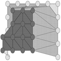
다음으로, 상기 색상 영상에 포함된 지점 중에서 적어도 둘 이상의 상기 메쉬에 대응되는 지점에는, 상기 지점에 대응되는 상기 깊이값 중에서 가장 작은 깊이값을 설정하는 단계(S312)가 수행될 수 있다. 예를 들어, 도 11의 왼쪽 부분에 포함된 지점과 같이, 일부 지점은 적어도 둘 이상의 메쉬와 겹칠 수 있다. 이러한 경우에는, 통상적인 Z-버퍼링 방법에 따라서, 대응되는 깊이값 중에서 가장 작은 깊이값이 상기 지점에 설정될 수 있다. 다시 말해서, 메쉬는 다른 메쉬에 의해 적어도 일부가 가려질 수 있다.Next, a minimum depth value among the depth values corresponding to the points may be set at a point corresponding to at least two of the points included in the color image (S312). For example, some points may overlap at least two or more meshes, such as the points included in the left portion of FIG. In this case, according to the conventional Z-buffering method, the smallest depth value among the corresponding depth values can be set at the above point. In other words, the mesh may be obscured at least partially by other meshes.
도 15는 본 발명의 실시예에 따라 메쉬에 포함된 각각의 지점에 깊이값이 설정된 결과를 나타낸 개념도이다. 도 15를 참조하면, 도 11에서의 투영된 메쉬 중에서 일부는 Z-버퍼링 방법에 의해 적어도 일부가 다른 메쉬에 의해 가려져 있다. 도 15를 참조하면, 검정색 부분의 메쉬에 대응되는 깊이값은 회색 부분의 메쉬에 대응되는 깊이값보다 작을 수 있다.15 is a conceptual diagram illustrating a result of setting depth values at respective points included in a mesh according to an embodiment of the present invention. Referring to FIG. 15, some of the projected meshes in FIG. 11 are partially obscured by other meshes by the Z-buffering method. Referring to FIG. 15, the depth value corresponding to the mesh of the black portion may be smaller than the depth value corresponding to the gray portion mesh.
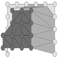
다시 도 13을 참조하면, 상기 투영된 메쉬 중에서, 다른 메쉬에 의해 가려지는 적어도 하나 이상의 정점을 포함하는 적어도 하나 이상의 메쉬 및 상기 불연속 지점을 중심으로 한 특정한 범위의 영역을 포함하는 불연속 영역을 검출하는 단계(S320)가 수행될 수 있다. 메쉬에 포함된 세 개의 정점 중에서 적어도 하나 이상의 정점이 다른 메쉬에 의해서 가려진 경우, 상기 메쉬의 내부의 영역은 불연속 영역이라고 판정될 수 있다. 또한, 상기 불연속 지점을 검출하는 단계(S210)에서 검출된 불연속 지점을 중심으로 한 특정한 범위의 영역은 불연속 영역이라고 판정될 수 있다.Referring again to FIG. 13, in the projected mesh, at least one mesh including at least one vertex covered by another mesh and a discontinuity region including a specific range of the center around the discontinuity point are detected Step S320 may be performed. If at least one of the three vertexes included in the mesh is covered by another mesh, the area inside the mesh may be determined as a discontinuous area. In addition, the region of the specific range centered on the discontinuity point detected in the step S210 of detecting the discontinuity point may be determined as a discontinuous region.
도 16은 본 발명의 실시예에 따라 불연속 영역이 검출된 결과를 나타낸 개념도이다. 도 16을 참조하면, 불연속 영역으로 검출된 영역의 내부에는 격자 무늬가 채워져 있다.16 is a conceptual diagram showing a result of detecting a discontinuous area according to an embodiment of the present invention. Referring to FIG. 16, a grid pattern is filled in a region detected as a discontinuous region.
다시 도 13을 참조하면, 다음으로, 상기 투영된 메쉬 중에서, 적어도 하나 이상의 상기 불연속 지점을 포함하는 적어도 하나 이상의 메쉬를 포함하는 홀(hole) 영역을 검출하는 단계(S330)가 수행될 수 있다. 도 17은 본 발명의 실시예에 따라 홀 영역이 검출된 결과를 나타낸 개념도이다. 도 17을 참조하면, 불연속 영역으로 검출된 영역의 내부에는 격자 무늬가 채워져 있다. 도 18은 본 발명의 실시예에 따라 불연속 영역 및 홀 영역이 검출된 결과를 시각적으로 나타낸 도면이다. 도 18에서 붉은색으로 표시된 영역은 불연속 영역에 대응되며, 초록색으로 표시된 영역은 홀 영역에 대응될 수 있다.Referring again to FIG. 13, a step S330 of detecting a hole area including at least one mesh including at least one discontinuity point among the projected meshes may be performed. 17 is a conceptual diagram showing a result of detection of a hole region according to an embodiment of the present invention. Referring to FIG. 17, a grid pattern is filled in a region detected as a discontinuous area. 18 is a diagram showing a result of detecting a discontinuous area and a hole area according to an embodiment of the present invention. In Fig. 18, the area indicated by red corresponds to the discontinuous area, and the area indicated with green corresponds to the hole area.
다시 도 13을 참조하면, 다음으로 상기 홀 영역의 내부에 적어도 하나 이상의 가상 정점을 생성하는 단계(S340)가 수행될 수 있다. 도 19는 본 발명의 실시예에 따라 홀 영역 내부에 가상 정점이 생성된 결과를 나타낸 개념도이다. 도 19를 참조하면, 홀 영역인 오른쪽 부분에 검정색의 가상 정점이 도시되어 있다.Referring again to FIG. 13, a step S340 of creating at least one virtual vertex in the hole region may be performed. 19 is a conceptual diagram showing a result of generating a virtual vertex in a hole region according to an embodiment of the present invention. Referring to FIG. 19, a black virtual vertex is shown on the right side, which is a hole area.
다시 도 13을 참조하면, 다음으로, 둘 이상의 영상 분할 방법을 이용하여 상기 깊이 맵이 투영된 상기 색상 영상을 분할하는 단계(S350)가 수행될 수 있다. 임의의 한 종류의 영상 분할(image segmentation) 방법이 다른 모든 영상 분할 방법들보다 항상 좋은 성능을 나타내지는 않는다고 볼 수 있다. 본 발명의 실시예에 따르면 적어도 둘 이상의 영상 분할 방법을 이용하여 고해상도에서의 객체의 경계를 보다 정확히 검출할 수 있다.Referring again to FIG. 13, a step S350 of dividing the color image on which the depth map is projected using two or more image segmentation methods may be performed. It can be seen that any one kind of image segmentation method does not always show better performance than all other image segmentation methods. According to the embodiment of the present invention, the boundary of an object at a high resolution can be more accurately detected by using at least two image segmentation methods.
도 20은 본 발명의 실시예에 따라 둘 이상의 영상 분할 방법을 이용하여 색상 영상이 분할되는 순서를 나타내는 순서도이다. 도 20을 참조하면, 상기 색상 영상을 분할하는 단계(S350)는 먼저, 제1 영상 분할 방법을 이용하여, 하나의 상기 정점 또는 하나의 상기 가상 정점을 포함하거나 상기 정점 및 상기 가상 정점을 포함하지 않는 적어도 하나 이상의 영역으로 상기 메쉬가 투영된 상기 색상 영상이 분할된 제1분할영상을 생성하는 단계(S351)가 수행될 수 있다. 다시 말해서, 분할된 하나의 영역에는 오직 하나의 정점 또는 가상 정점을 포함하거나, 정정 또는 가상 정점 중에서 어느 것도 포함하지 않을 수 있다.FIG. 20 is a flowchart illustrating a procedure of dividing a color image using two or more image segmentation methods according to an embodiment of the present invention. Referring to FIG. 20, in step S350, the color image is divided into a plurality of vertices or a plurality of virtual vertices by using a first image segmentation method, (S351) may be performed to generate a first divided image in which the color image projected from the mesh is divided into at least one or more regions. In other words, one divided area may contain only one vertex or virtual vertex, or may not contain either a correction or a virtual vertex.
예를 들어 상기 제1 영상 분할 방법은 SLIC 영상 분할 방법일 수 있다. 상기 방법에 따르면 색상 영상에 포함된 모든 지점은 상기 지점과 가장 가까운 정점과 동일한 영역 내에 포함되도록 분할될 수 있다. 이 때, 상기 지점으로부터 상기 정점까지의 거리는 상기 지점 및 상기 정점의 색상의 차이 및 위치의 차이를 각각 제곱한 뒤 가중치를 부여하여 합산한 결과일 수 있다. For example, the first image segmentation method may be an SLIC image segmentation method. According to the method, all the points included in the color image can be divided so as to be included in the same area as the vertex closest to the point. In this case, the distance from the point to the apex may be a result of squaring each of the difference in color and position of the point and the apex, adding weights, and summing the weights.
이 때, 제1지점과 가장 가까운 정점 사이에, 상기 정점이 포함된 영역과 다른 영역에 포함된 제2지점이 존재함으로써 제1지점과 상기 정점이 서로 물리적으로 연결이 될 수 없는 경우가 있을 수 있다. 이 경우에는, 상기 제1지점은 정점 또는 가상 정점 중에서 어느 것도 포함되지 않은 영역에 속하는 것으로 정의될 수 있다. 도 21은 본 발명의 실시예에 따라 제1 영상 분할 방법을 이용하여 색상 영상이 분할된 결과를 시각적으로 나타낸 도면이다.At this time, there may be a case where the first point and the vertex can not be physically connected to each other because there is a second point between the vertex closest to the first point and the second vertex included in another region including the vertex have. In this case, the first point may be defined as belonging to an area that does not include either a vertex or a virtual vertex. FIG. 21 is a diagram showing a result of dividing a color image using a first image segmentation method according to an embodiment of the present invention.
다시 도 20을 참조하면, 다음으로, 상기 제1 영상 분할 방법과 서로 다른 제2 영상 분할 방법 이용하여 하나의 상기 정점 또는 하나의 상기 가상 정점을 포함하거나 상기 정점 및 상기 가상 정점을 포함하지 않는 적어도 하나 이상의 영역으로 상기 메쉬가 투영된 상기 색상 영상이 분할된 제2분할영상을 생성하는 단계(S352)가 수행될 수 있다.Referring to FIG. 20 again, at least one vertex or one virtual vertex is included or a plurality of virtual vertices including no vertex and the virtual vertex are generated using a second image segmentation method different from the first image segmentation method A step S352 of generating a second divided image in which the color image projected from the mesh is divided into one or more regions may be performed.
상기 제2 영상 분할 방법은 EGB 영상 분할 방법일 수 있다. 상기 방법에 따르면, 인접한 모든 지점에 대해서 색상 차이가 문턱치보다 작은 경우 서로 연결되어 동일한 영역 내에 포함될 수 있다. 상기 문턱치는 서로 연결되어 이루어진 영역의 크기에 반비례할 수 있다. 다시 말해서, 영역이 커지면 커질수록 문턱치가 작아지므로, 새로운 지점이 동일한 영역 내에 포함될 수 있는 가능성은 점점 낮아질 수 있다. The second image segmentation method may be an EGB image segmentation method. According to the above method, when the color difference is smaller than the threshold value for all adjacent points, they can be connected to each other and included in the same area. The threshold value may be inversely proportional to the size of the area connected to each other. In other words, the larger the area, the smaller the threshold value, so the possibility that a new point can be included in the same area can be lowered.
만약 두 지점 중 한 지점이 정점이거나, 두 지점 중 한 지점이 정점이 포함된 영역에 속하는 경우에는, 두 지점이 연결되어 생성된 영역의 레이블이 상기 정점의 레이블로 치환될 수 있다. 만약 두 지점 모두 정점이거나, 정점가 포함된 영역 내에에 속하는 경우에는 두 지점을 연결할 필요가 없다. 도 22는 본 발명의 실시예에 따라 제2 영상 분할 방법을 이용하여 색상 영상이 분할된 결과를 시각적으로 나타낸 도면이다.If one of the two points is a vertex, or one of the two points belongs to an area containing a vertex, the label of the vertex may be replaced with the label of the generated area. If both points are vertices, or if they belong to an area containing vertices, it is not necessary to connect the two points. 22 is a diagram showing a result of dividing a color image using a second image segmentation method according to an embodiment of the present invention.
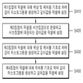
다시 도 13을 참조하면, 상기 분할 결과에 따라 각각의 지점들을 하나 이상의 집합으로 분류하는 단계(S360)가 수행될 수 있다. 도 23은 본 발명의 실시예에 따라 색상 영상의 각각의 지점들을 하나 이상의 집합으로 분류하는 순서를 나타내는 순서도이다.Referring again to FIG. 13, classification of each point into one or more sets according to the division result (S360) may be performed. 23 is a flowchart showing a procedure of sorting each point of a color image into one or more sets according to an embodiment of the present invention.
도 23을 참조하면, 상기 분할 결과에 따라 각각의 지점들을 하나 이상의 집합으로 분류하는 단계(S360)는 먼저, 적어도 하나 이상의 영역으로 상기 깊이 맵이 분할된 제3분할영상을 생성하고, 상기 제3분할영상에 포함된 각각의 영역에 서로 다른 레이블을 설정하는 단계(S361)가 수행될 수 있다.Referring to FIG. 23, in step S360 of classifying each point into one or more sets according to the division result, a third divided image in which the depth map is divided into at least one region is generated, A step S361 of setting different labels in the respective regions included in the divided images may be performed.
깊이 맵은 예를 들어, Watershed 또는 EGB 영상 분할 방식 등을 이용하여 영상 분할(image segmentation)될 수 있다. 또한 분할된 각각의 영역에는 서로 다른 레이블이 설정될 수 있다. 도 24는 본 발명의 실시예에 따라 깊이 맵이 분할된 분할영상을 시각적으로 나타낸 도면이다. 도 24를 참조하면, 서로 다른 레이블을 갖는 영역은 서로 다른 색으로 도시되어 있다.The depth map may be image segmentation using, for example, a Watershed or EGB image segmentation method. Also, different labels may be set for each divided area. FIG. 24 is a diagram showing a divided image obtained by dividing a depth map according to an embodiment of the present invention. FIG. Referring to FIG. 24, areas having different labels are shown in different colors.
다시 도 23을 참조하면, 다음으로, 상기 제1분할영상에 포함된 각각의 영역에 포함된 상기 정점에 대응되는 상기 제3분할영상의 영역에 설정된 상기 레이블에 대응하는 레이블을 상기 제1분할영상에 포함된 각각의 영역에 설정하는 단계(S362)가 수행될 수 있다.Referring again to FIG. 23, a label corresponding to the label set in the region of the third divided image corresponding to the vertex included in each of the regions included in the first divided image is referred to as the first divided image (S362) may be performed.
도 25는 본 발명의 실시예에 따라 제1 영상 분할 방법을 이용하여 분할된 각각의 영역에 레이블이 설정된 결과를 시각적으로 나타낸 도면이다. 도 25를 참조하면, 서로 다른 레이블을 갖는 영역은 서로 다른 색으로 도시되어 있다. 도 25를 참조하면, 도 21에서의 상당수의 영역들이 서로 병합되었음을 확인할 수 있다.FIG. 25 is a diagram visually showing a result of setting a label in each divided area using the first image segmentation method according to an embodiment of the present invention. FIG. Referring to Fig. 25, regions having different labels are shown in different colors. Referring to FIG. 25, it is confirmed that a large number of areas in FIG. 21 are merged with each other.
다시 도 23을 참조하면, 다음으로, 상기 제2분할영상에 포함된 각각의 영역에 포함된 상기 정점에 대응되는 상기 제3분할영상의 영역에 설정된 상기 레이블에 대응하는 레이블을 상기 제2분할영상에 포함된 각각의 영역에 설정하는 단계(S363)가 수행될 수 있다.Referring again to FIG. 23, a label corresponding to the label set in the region of the third divided image corresponding to the vertex included in each region included in the second divided image is referred to as the second divided image (Step S363) may be performed.
도 26은 본 발명의 실시예에 따라 제2 영상 분할 방법을 이용하여 분할된 각각의 영역에 레이블이 설정된 결과를 시각적으로 나타낸 도면이다. 도 26을 참조하면, 서로 다른 레이블을 갖는 영역은 서로 다른 색으로 도시되어 있다. 도 26를 참조하면, 도 22에서의 상당수의 영역들이 서로 병합되었음을 확인할 수 있다.FIG. 26 is a diagram showing a result of setting a label in each of divided areas using the second image segmentation method according to an embodiment of the present invention. FIG. Referring to FIG. 26, regions having different labels are shown in different colors. Referring to FIG. 26, it is confirmed that a large number of areas in FIG. 22 are merged with each other.
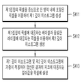
다시 도 23을 참조하면, 상기 제1분할영상에 포함된 각각의 제1픽셀 중에서, 상기 제1픽셀에 대응되는 상기 레이블이 상기 제1픽셀에 대응되는 상기 제2분할영상의 제2픽셀에 대응되는 상기 레이블과 서로 동일한 적어도 하나 이상의 상기 제1픽셀을 포함하는 제1집합을 생성하는 단계(S364)가 수행될 수 있다. Referring again to FIG. 23, among the first pixels included in the first divided image, the label corresponding to the first pixel corresponds to the second pixel of the second divided image corresponding to the first pixel (S364) may be performed to generate a first set including at least one or more first pixels that are the same as the label.
다음으로, 상기 제1픽셀 중에서, 상기 제1픽셀에 대응되는 상기 영역 또는 상기 제1픽셀에 대응되는 상기 제2픽셀에 대응되는 상기 영역 중에서 적어도 하나 이상이 상기 가상 정점을 포함하는 적어도 하나 이상의 상기 제1픽셀을 포함하는 제2집합을 생성하는 단계(S365)가 수행될 수 있다. 다시 말해서, 제2집합은 홀 영역에 포함되어 있던 픽셀을 포함할 수 있다.At least one of the regions corresponding to the first pixels or the regions corresponding to the second pixels corresponding to the first pixels among the first pixels includes at least one of the regions including the virtual vertices, A step S365 of generating a second set including the first pixel may be performed. In other words, the second set may include the pixels contained in the hole area.
다음으로, 상기 각각의 제1픽셀 중에서, 상기 제1픽셀에 대응되는 상기 레이블이 상기 제1픽셀에 대응되는 상기 제2픽셀에 대응되는 상기 레이블과 서로 다르고, 상기 제1픽셀에 대응되는 상기 영역 또는 상기 제1픽셀에 대응되는 상기 제2픽셀에 대응되는 상기 영역 중에서 적어도 하나 이상이 상기 정점을 포함하는 적어도 하나 이상의 상기 제1픽셀을 포함하는 제3집합을 생성하는 단계(S366)가 수행될 수 있다. 다시 말해서, 제3집합은 제1 영상 분할 방식을 기초로 한 결과와 제2 영상 분할 방식을 기초로 한 결과가 서로 다른 픽셀들을 포함할 수 있다.Next, among the first pixels, the label corresponding to the first pixel is different from the label corresponding to the second pixel corresponding to the first pixel, and the label corresponding to the first pixel (S366) is performed to generate a third set including at least one or more of the first pixels including at least one of the regions corresponding to the first pixels or the regions corresponding to the second pixels corresponding to the first pixels . In other words, the third set may include pixels having different results based on the first image segmentation scheme and the second image segmentation scheme.
다음으로, 상기 각각의 제1픽셀 중에서, 상기 제1픽셀에 대응되는 상기 영역 및 상기 제1픽셀에 대응되는 상기 제2픽셀에 대응되는 상기 영역이 상기 정점 및 상기 가상 정점을 포함하지 않는 적어도 하나 이상의 상기 제1픽셀을 포함하는 제4집합을 생성하는 단계(S367)가 수행될 수 있다. 다시 말해서, 제4집합은 정점 또는 가상 정점을 포함하는 영역에 속하지 않는 픽셀들을 포함할 수 있다. Next, among the first pixels, the region corresponding to the first pixel and the region corresponding to the second pixel corresponding to the first pixel do not include the vertex and the virtual vertex, and at least one The generating of the fourth set including the first pixel (S367) may be performed. In other words, the fourth set may include pixels that do not belong to a region including a vertex or a virtual vertex.
상술한 바와 같이, 임의의 제1지점과 가장 가까운 정점 사이에, 상기 정점이 포함된 영역과 다른 영역에 포함된 제2지점이 존재함으로써 제1지점과 상기 정점이 서로 물리적으로 연결이 될 수 없는 경우가 있을 수 있다. 이 경우에는, 상기 제1지점은 정점 또는 가상 정점 중에서 어느 것도 포함되지 않은 영역에 속하는 것으로 정의될 수 있다. 제4집합은 상기 제1지점을 포함할 수 있다. As described above, between the arbitrary first point and the closest vertex, there is a second point included in the region different from the region including the vertex, so that the first point and the vertex can not be physically connected to each other There may be cases. In this case, the first point may be defined as belonging to an area that does not include either a vertex or a virtual vertex. And the fourth set may include the first point.
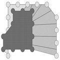
도 27은 본 발명의 실시예에 따라 색상 영상의 각각의 지점들이 하나 이상의 집합으로 분류된 결과를 시각적으로 나타낸 도면이다. 도 27을 참조하면, 제1집합에 포함된 픽셀들은 회색으로 도시되어 있으며, 제2집합에 포함된 픽셀들은 흰색으로 도시되어 있다. 또한, 제3집합에 포함된 픽셀들은 초록색으로 도시되어 있으며, 제4집합에 포함된 픽셀들은 붉은색으로 도시되어 있다.FIG. 27 is a diagram showing a result of visualizing each of the points of a color image classified into one or more sets according to an embodiment of the present invention. Referring to FIG. 27, the pixels included in the first set are shown in gray, and the pixels included in the second set are shown in white. In addition, the pixels included in the third set are shown in green, and the pixels included in the fourth set are shown in red.
다시 도 1을 참조하면, 상기 집합에 포함된 상기 색상 영상의 지점에 깊이값을 설정하는 단계(S400)가 수행될 수 있다. 도 28은 본 발명의 실시예에 따라 집합에 포함된 지점에 깊이값을 설정하는 순서를 나타내는 순서도이다.Referring again to FIG. 1, setting a depth value at a point of the color image included in the set (S400) may be performed. 28 is a flowchart showing a procedure of setting a depth value at a point included in the set according to an embodiment of the present invention.
도 28을 참조하면, 상기 집합에 포함된 상기 색상 영상의 지점에 깊이값을 설정하는 단계(S400)는 먼저, 제1집합의 픽셀에 대해 색상 및 위치를 기초로 하여 깊이 히스토그램을 생성하고 깊이값을 픽셀에 설정하는 단계(S410)가 수행될 수 있다.Referring to FIG. 28, in step S400, a depth value is set at a point of the color image included in the set. First, a depth histogram is generated based on hue and position for a first set of pixels, (S410) may be performed.
도 29는 본 발명의 실시예에 따라 제1집합의 픽셀에 대해 깊이 히스토그램이 생성되고 깊이값이 픽셀에 설정되는 순서를 나타내는 순서도이다. 도 29를 참조하면, 먼저, 상기 제1집합에 포함된 각각의 제3픽셀에 대하여 제1 깊이 히스토그램이 생성되는 단계(S411)가 수행될 수 있다. 29 is a flowchart showing a sequence in which a depth histogram is generated for a first set of pixels and depth values are set in pixels according to an embodiment of the present invention. Referring to FIG. 29, a first depth histogram may be generated for each third pixel included in the first set (S411).
상기 제1 깊이 히스토그램은, 상기 제3픽셀을 중심으로 한 특정한 범위의 영역 내에 포함되고 상기 깊이값이 설정된 적어도 하나 이상의 제4픽셀의 상기 깊이값, 상기 제3픽셀과 상기 제4픽셀의 위치 차이 및 상기 제3픽셀과 상기 제4픽셀의 색상 차이를 이용하여 생성될 수 있다. 예를 들어, 제1 깊이 히스토그램은 다음의 수학식 4를 이용하여 생성될 수 있다.Wherein the first depth histogram includes the depth value of at least one or more fourth pixels included in a region of a specific range centered on the third pixel and in which the depth value is set, And a color difference between the third pixel and the fourth pixel. For example, the first depth histogram may be generated using the following equation (4).

상기 수학식 4에서, G는 가우시안 가중치 함수이다. Ix는 픽셀 x의 색상을 나타낸다. x'은 x를 중심으로 한 특정한 범위의 영역 W(x)에 포함된 픽셀들 중에서 깊이값이 설정된 픽셀을 나타낸다. d'은 상기 깊이값이 설정된 픽셀의 깊이값을 나타낸다.In Equation (4), G is a Gaussian weight function. Ix represents the color of the pixel x. x 'represents a pixel in which a depth value is set among pixels included in a specific range of the area W (x) centered at x. d 'represents the depth value of the pixel for which the depth value is set.
다음으로, 상기 제3픽셀에 대응하는 레이블과 서로 동일한 레이블에 대응되는 적어도 하나 이상의 제5픽셀의 상기 깊이값, 상기 제3픽셀과 상기 제5픽셀의 위치 차이 및 상기 제3픽셀과 상기 제5픽셀의 색상 차이를 이용하여 제2 깊이 히스토그램이 생성되는 단계(S412)가 수행될 수 있다. 예를 들어, 제2 깊이 히스토그램은 다음의 수학식 5를 이용하여 생성될 수 있다.Next, the depth value of at least one fifth pixel corresponding to the same label as the label corresponding to the third pixel, the positional difference between the third pixel and the fifth pixel, and the difference between the third pixel and the fifth pixel The step of generating the second depth histogram using the color difference of the pixel (S412) may be performed. For example, the second depth histogram can be generated using the following equation (5).

상기 수학식 5에서, R(x)는 상술한 영상 분할 방법에 의해서 분할되고 픽셀 x를 포함하는 영역에 포함된 픽셀의 집합이다.In Equation (5), R (x) is a set of pixels divided by the above-described image segmentation method and included in an area including the pixel x.
다음으로, 상기 제1 깊이 히스토그램 및 상기 제2 깊이 히스토그램에 가중치가 적용되어 합산된 결과의 피크(peak)에 대응되는 상기 깊이값이 상기 제3픽셀의 깊이값으로서 설정되는 단계(S413)가 수행될 수 있다. 상기 제1 깊이 히스토그램 및 상기 제2 깊이 히스토그램에 가중치가 적용되어 합산된 결과는 다음의 수학식 6과 같이 표현될 수 있다.Next, a step S413 of setting the depth value corresponding to a peak of a result obtained by weighting the first depth histogram and the second depth histogram as a depth value of the third pixel is performed . The result obtained by applying the weights to the first depth histogram and the second depth histogram may be expressed as Equation (6).

다시 도 28을 참조하면, 다음으로, 상기 제2집합에 포함된 각각의 제6픽셀은, 상기 제6픽셀의 색상 및 상기 제6픽셀의 위치를 기초로 하여 선택되고 상기 깊이값이 설정된 하나의 제7픽셀을 포함하는 적어도 하나 이상의 서브집합으로 분할되고, 상기 각각의 제6픽셀의 깊이값으로서 상기 제6픽셀이 포함된 상기 서브집합에 포함된 상기 제7픽셀의 깊이값이 설정되는 단계(S420)가 수행될 수 있다.Referring again to FIG. 28, next, each sixth pixel included in the second set is selected based on the color of the sixth pixel and the position of the sixth pixel, and the depth value is set to one A depth value of the seventh pixel included in the subset including the sixth pixel is set as a depth value of each sixth pixel, the depth value being divided into at least one subset including a seventh pixel S420) may be performed.
도 30은 본 발명의 실시예에 따라 제2집합의 픽셀이 서브집합으로 분할된 결과를 나타낸 개념도이다. 홀 영역 주변의 일부 픽셀들에는 깊이값이 설정되게 된다. 따라서, 제2집합은 상기 픽셀들을 정점으로서 Watershed 알고리즘 또는 EGB 영상 분할 방법 등을 이용하여 서브집합으로 분할될 수 있다. 이로써, 홀 영역에 포함된 모든 픽셀은 하나의 정점과 동일한 영역 내에 포함될 수 있다. 또한, 상기 서브집합에 포함된 픽셀들의 깊이값으로서 상기 새로운 정점의 깊이값이 설정될 수 있다. 도 31은 본 발명의 실시예에 따라 제2집합의 픽셀에 깊이값이 설정된 결과를 시각적으로 나타낸 도면이다.30 is a conceptual diagram illustrating a result of dividing a second set of pixels into subsets according to an embodiment of the present invention. Depth values are set for some pixels around the hole area. Accordingly, the second set can be divided into sub-sets using the Watershed algorithm or the EGB image segmentation method or the like using the pixels as vertices. Thereby, all the pixels included in the hole area can be included in the same area as one vertex. Also, the depth value of the new vertex may be set as the depth value of the pixels included in the subset. 31 is a diagram showing a result of visually showing a result of setting a depth value in a second set of pixels according to an embodiment of the present invention.
다시 도 28을 참조하면, 다음으로, 제3집합의 픽셀에 대해 색상 및 위치를 기초로 하여 깊이 히스토그램을 생성하고 깊이값을 픽셀에 설정하는 단계(S430)가 수행될 수 있다. 도 32는 본 발명의 실시예에 따라 제3집합의 픽셀에 대해 깊이 히스토그램이 생성되고 깊이값이 픽셀에 설정되는 순서를 나타내는 순서도이다.Referring again to FIG. 28, a depth histogram may be generated based on hue and position for a third set of pixels, and a step of setting a depth value to a pixel (S430) may be performed. 32 is a flowchart showing a sequence in which a depth histogram is generated for a third set of pixels and depth values are set in pixels according to an embodiment of the present invention.
도 32를 참조하면, 먼저, 상기 제3집합에 포함된 각각의 제8픽셀에 대하여, 상기 제8픽셀을 중심으로 한 특정한 범위의 영역 내에 포함되고 상기 깊이값이 설정된 적어도 하나 이상의 제9픽셀의 상기 깊이값, 상기 제8픽셀과 상기 제9픽셀의 위치 차이 및 상기 제8픽셀과 상기 제9픽셀의 색상 차이를 이용하여 제3 깊이 히스토그램이 생성되는 단계(S431)가 수행될 수 있다.Referring to FIG. 32, for each eighth pixel included in the third set, at least one or more ninth pixels included in a specific range region centered on the eighth pixel and having the depth value set The third depth histogram may be generated using the depth value, the positional difference between the eighth pixel and the ninth pixel, and the color difference between the eighth pixel and the ninth pixel (S431).
다음으로, 상기 제8픽셀에 대응하는 레이블과 서로 동일한 레이블에 대응되는 적어도 하나 이상의 제10픽셀의 상기 깊이값, 상기 제8픽셀과 상기 제10픽셀의 위치 차이 및 상기 제8픽셀과 상기 제10픽셀의 색상 차이를 이용하여 제4 깊이 히스토그램이 생성되는 단계(S432)가 수행될 수 있다.Next, the depth value of at least one tenth pixel corresponding to the same label as the label corresponding to the eighth pixel, the positional difference between the eighth pixel and the tenth pixel, and the difference between the eighth pixel and the tenth The fourth depth histogram may be generated using the color difference of pixels (S432).
다음으로, 상기 제3집합을 둘러싸고 상기 깊이값이 설정된 적어도 하나 이상의 제11픽셀의 상기 깊이값, 상기 제8픽셀과 상기 제11픽셀의 위치 차이 및 상기 제8픽셀과 상기 제11픽셀의 색상 차이를 이용하여 제5 깊이 히스토그램이 생성되는 단계(S433)가 수행될 수 있다. 상기 제5 깊이 히스토그램은 다음의 수학식 7과 같이 표현될 수 있다.Next, the depth value of the at least one eleventh pixel surrounding the third set and having the depth value set, the positional difference between the eighth pixel and the eleventh pixel, and the color difference between the eighth pixel and the eleventh pixel (S433) may be performed in which the fifth depth histogram is generated using the second depth histogram. The fifth depth histogram may be expressed by the following Equation (7).

상기 수학식 7에서, SRND는 상기 제3집합을 둘러싸고 상기 깊이값이 설정된 픽셀들을 포함하는 집합이다.In Equation (7), SRND is a set that surrounds the third set and includes the pixels for which the depth value is set.
다음으로, 상기 제3 깊이 히스토그램, 상기 제4 깊이 히스토그램 및 상기 제5 깊이 히스토그램에 가중치가 적용되어 합산된 합산 히스토그램이 생성되는 단계(S434)가 수행될 수 있다. 상기 합산 히스토그램은 다음의 수학식 8과 같이 표현될 수 있다.Next, a summed histogram may be generated by applying weights to the third depth histogram, the fourth depth histogram, and the fifth depth histogram (S434). The summation histogram can be expressed as Equation (8).

도 33은 본 발명의 다른 실시예에 따라 제3집합의 픽셀에 대해 깊이 히스토그램이 생성되고 깊이값이 픽셀에 설정되는 순서를 나타내는 순서도이다.33 is a flowchart illustrating a procedure in which a depth histogram is generated for a third set of pixels and a depth value is set for pixels according to another embodiment of the present invention.
본 발명의 다른 실시예에 따르면, 먼저, 상기 제3집합에 포함된 각각의 제8픽셀에 대하여, 상기 제8픽셀을 중심으로 한 특정한 범위의 영역 내에 포함되고 상기 깊이값이 설정된 적어도 하나 이상의 제9픽셀의 상기 깊이값, 상기 제8픽셀과 상기 제9픽셀의 위치 차이 및 상기 제8픽셀과 상기 제9픽셀의 색상 차이를 이용하여 제3 깊이 히스토그램이 생성되는 단계(S441)가 수행될 수 있다.According to another embodiment of the present invention, first, for each eighth pixel included in the third set, at least one or more pixels included in a region of a specific range centered on the eighth pixel, A step S441 may be performed in which the third depth histogram is generated using the depth value of 9 pixels, the positional difference between the eighth pixel and the ninth pixel, and the color difference between the eighth pixel and the ninth pixel have.
다음으로, 상기 제8픽셀에 대응하는 레이블과 서로 동일한 레이블에 대응되는 적어도 하나 이상의 제10픽셀의 상기 깊이값, 상기 제8픽셀과 상기 제10픽셀의 위치 차이 및 상기 제8픽셀과 상기 제10픽셀의 색상 차이를 이용하여 제4 깊이 히스토그램이 생성되는 단계(S442)가 수행될 수 있다.Next, the depth value of at least one tenth pixel corresponding to the same label as the label corresponding to the eighth pixel, the positional difference between the eighth pixel and the tenth pixel, and the difference between the eighth pixel and the tenth A step S442 in which the fourth depth histogram is generated using the color difference of pixels may be performed.
다음으로, 상기 제3집합을 둘러싸고 상기 깊이값이 설정된 적어도 하나 이상의 제11픽셀의 상기 깊이값, 상기 제8픽셀과 상기 제11픽셀의 위치 차이 및 상기 제8픽셀과 상기 제11픽셀의 색상 차이를 이용하여 제5 깊이 히스토그램이 생성되는 단계(S443)가 수행될 수 있다.Next, the depth value of the at least one eleventh pixel surrounding the third set and having the depth value set, the positional difference between the eighth pixel and the eleventh pixel, and the color difference between the eighth pixel and the eleventh pixel May be performed to generate the fifth depth histogram (S443).
다음으로, 상기 제8픽셀과 인접한 픽셀과 상기 제8픽셀의 색상 차이를 기초로 한 가중치 및 상기 합산 히스토그램을 이용하여 모델링된 마르코프 무작위 필드(Markov Random Field) 점수를 최대화하는 깊이값이 상기 제8픽셀의 깊이값으로서 설정되는 단계(S444)가 수행될 수 있다. 상기 제8픽셀과 인접한 픽셀과 상기 제8픽셀의 색상 차이를 기초로 한 가중치 및 상기 합산 히스토그램을 이용하여 모델링된 마르코프 무작위 필드 점수는 예를 들어, 다음의 수학식 9와 같이 표현될 수 있다.Next, a weight value based on a color difference between the pixel adjacent to the eighth pixel and the eighth pixel, and a depth value maximizing a Markov random field model modeled using the summation histogram, A step S444 may be performed, which is set as the depth value of the pixel. A weight based on the color difference between the pixel adjacent to the eighth pixel and the eighth pixel, and a Markov random field score modeled using the summation histogram may be expressed as Equation (9), for example.

상기 수학식 9에서 px는 깊이 히스토그램의 퀀타이제이션(quantization) 레벨과 동일한 레벨을 갖는 벡터이다. 또한, px는 만약 x가 d라는 깊이값을 갖는 경우 다음과 같이 설정된다. d번째 요소인 px(d)는 1이고, 나머지 요소는 모두 0이다. 상기 Wx,y는 인접한 두 픽셀의 색상 차이를 기초로 한 가중치로서 다음의 수학식 10과 같이 표현될 수 있다.In Equation (9), px is a vector having the same level as the quantization level of the depth histogram. Also, px is set as follows if x has a depth value of d. The d-th element px (d) is 1 and the remaining elements are all 0s. Wx, y is a weight based on the color difference between two adjacent pixels, and can be expressed as Equation (10).

상기 수학식 10에서 δ(x)는 x가 0인 경우 1이고 그렇지 않은 경우 0인 함수이다. ![]()
![]()
상기 마르코프 무작위 필드 점수에 대한 함수인 S({p})를 최대화시키는 {p}는 릴렉세이션 레이블링(relaxation labeling) 알고리즘을 이용하여 계산될 수 있다. 릴렉세이션 레이블링 알고리즘에 따르면 다음의 수학식 11에서와 같이 p가 산출될 수 있다.{P} maximizing the function S ({p}) for the Markov random field score can be computed using a relaxation labeling algorithm. According to the relaxation labeling algorithm, p can be calculated as shown in the following Equation (11).

상기 수학식 11에서 "old" 레이블이 붙어있는 변수는 이터레이션(iteration) 과정에서 바로 이전의 값을 나타낸다. 또한, "new" 레이블이 붙어있는 변수는 이터레이션 과정에서 현재 갱신된 값을 나타낸다.The variable labeled "old" in Equation (11) represents a previous value in the iteration process. Also, a variable labeled "new" indicates the current value updated during the iteration process.
다시 도 28을 참조하면 제4집합의 픽셀에 대해 위치를 기초로 하여 깊이 히스토그램을 생성하고 깊이값을 픽셀에 설정하는 단계(S450)가 수행될 수 있다. 도 34는 본 발명의 실시예에 따라 제4집합의 픽셀에 대해 깊이 히스토그램이 생성되고 깊이값이 픽셀에 설정되는 순서를 나타내는 순서도이다.Referring again to FIG. 28, a depth histogram may be generated based on the position of the fourth set of pixels and a depth value may be set to a pixel (S450). FIG. 34 is a flowchart showing a sequence in which a depth histogram is generated for a fourth set of pixels and depth values are set in pixels according to an embodiment of the present invention. FIG.
도 34를 참조하면, 먼저, 상기 제4집합에 포함된 각각의 제12픽셀에 대하여, 상기 제4집합을 둘러싸고 상기 깊이값이 설정된 적어도 하나 이상의 제13픽셀의 상기 깊이값 및 상기 제12픽셀과 상기 제13픽셀의 위치 차이를 이용하여 깊이 히스토그램이 생성되는 단계(S451)가 수행될 수 있다. 다음으로, 상기 깊이 히스토그램의 피크(peak)에 대응되는 상기 깊이값이 상기 제12픽셀의 깊이값으로서 설정되는 단계(S452)가 수행될 수 있다.Referring to FIG. 34, first, for each of the twelfth pixels included in the fourth set, the depth value of the at least one thirteenth pixel surrounding the fourth set and having the depth value set, The step of generating the depth histogram using the positional difference of the thirteenth pixel (S451) may be performed. Next, the depth value corresponding to the peak of the depth histogram may be set as the depth value of the twelfth pixel (S452).
도 35는 본 발명의 실시예에 따라 제4집합을 둘러싸는 픽셀을 이용하여 깊이 히스토그램이 생성되는 과정을 설명하기 위한 참고도이다.35 is a reference diagram for explaining a process of generating a depth histogram using pixels surrounding a fourth set according to an embodiment of the present invention.
도 35를 참조하면, 화살표가 가리키고 있는 영역에 속한 제1지점과 오른쪽 큰 사각형 영역의 임의의 제2지점 사이에 왼쪽 큰 사각형 영역에 포함된 제3지점들이 존재함으로써, 제1지점은 제2지점과 서로 물리적으로 연결될 수 있다. 이 경우, 상기 화살표가 가리키고 있는 영역을 둘러싸고 깊이값이 설정된 왼쪽 큰 사각형 영역 내의 제3지점을 이용하여 깊이 히스토그램이 생성될 수 있다. 깊이 히스토그램은 다음의 수학식 12와 같이 표현될 수 있다.Referring to FIG. 35, since there are third points included in the left large rectangular area between the first point belonging to the area indicated by the arrow and any second point of the right large rectangular area, And may be physically connected to each other. In this case, a depth histogram can be generated using a third point in the left large rectangular area surrounding the area indicated by the arrow and having a depth value set. The depth histogram can be expressed as the following equation (12).

도 36은 본 발명의 다른 실시예에 따라 제4집합의 픽셀에 대해 깊이 히스토그램이 생성되고 깊이값이 픽셀에 설정되는 순서를 나타내는 순서도이다. 도 36을 참조하면, 본 발명의 다른 실시예에 따른 경우 먼저, 상기 제4집합에 포함된 각각의 제12픽셀에 대하여, 상기 제4집합을 둘러싸고 상기 깊이값이 설정된 적어도 하나 이상의 제13픽셀의 상기 깊이값 및 상기 제12픽셀과 상기 제13픽셀의 위치 차이를 이용하여 깊이 히스토그램이 생성되는 단계(S461)가 수행될 수 있다. FIG. 36 is a flowchart showing a sequence in which a depth histogram is generated for a fourth set of pixels and depth values are set in pixels according to another embodiment of the present invention. FIG. Referring to FIG. 36, according to another embodiment of the present invention, for each of the twelfth pixels included in the fourth set, at least one or more thirteen pixels surrounding the fourth set and having the depth value set therein The step of generating the depth histogram using the depth value and the positional difference between the twelfth pixel and the thirteenth pixel (S461) may be performed.
다음으로, 상기 제12픽셀과 인접한 픽셀과 상기 제12픽셀의 색상 차이를 기초로 한 가중치 및 상기 깊이 히스토그램을 이용하여 모델링된 마르코프 무작위 필드(Markov Random Field) 점수를 최대화하는 깊이값이 상기 제12픽셀의 깊이값으로서 설정되는 단계(S462)가 수행될 수 있다.Next, a weight value based on the color difference between the pixel adjacent to the twelfth pixel and the twelfth pixel, and a depth value maximizing the Markov random field score modeled using the depth histogram, A step S462 may be performed, which is set as the depth value of the pixel.
다시 도 1을 참조하면, 다음으로, 상기 깊이값이 설정된 상기 색상 영상을 출력하는 단계(S500)가 수행될 수 있다. 도 37은 본 발명의 실시예에 따라 깊이값이 설정된 색상 영상이 출력된 결과를 시각적으로 나타낸 도면이다. 또한, 상기 출력 결과에 영상 후처리(post processing)을 통하여 엣지 보존 스무딩(edge-preserving smoothing) 등을 적용하는 경우, 더욱 정확한 깊이 맵이 획득될 수 있다.Referring again to FIG. 1, a step S500 of outputting the color image having the depth value set therein may be performed. FIG. 37 is a diagram showing a result of outputting a color image in which a depth value is set according to an embodiment of the present invention. Further, when edge-preserving smoothing or the like is applied to the output result through image post-processing, a more accurate depth map can be obtained.
도 38은 본 발명의 실시예에 따른 영상 처리 장치(100)의 구성을 나타내는 블록도이다. 도 38을 참조하면, 본 발명의 실시예에 따른 영상 처리 장치(100)는, 입력부(110), 이미지 처리부(120), 및 출력부(130)를 포함할 수 있다.38 is a block diagram showing the configuration of the
입력부(110)는 특정한 장면(scene)에 대한 깊이 맵 또는 색상 영상을 수신하거나 생성할 수 있다. 입력부(110)는 외부로부터 깊이 맵 및 색상 영상을 수신할 수 있다. 또한, 입력부(110)는 예를 들어, 스테레오스코픽 카메라(stereoscopic camera), 패턴 프로젝션 카메라(pattern projection camera), TOF(Time Of Flight) 카메라, 또는 유사한 측정 장치 중에서 어느 하나인 깊이 센서를 포함할 수 있다. 또한, 입력부(110)는 예를 들어, CMOS 카메라, CCD 카메라(Charge-Coupled Device camera), 또는 유사한 촬영 장치 중에서 어느 하나인 광학 촬영 장치를 포함할 수 있다.The
입력부(110)에 대한 상세한 내용은 상술한 깊이 맵 및 색상 영상을 수신하는 단계(S100)와 대응되므로 자세한 설명은 생략하기로 한다.The details of the
이미지 처리부(120)는 상기 깊이 맵에 포함된 각각의 지점을 상기 색상 영상에 투영하고, 상기 깊이 맵이 투영된 상기 색상 영상을 적어도 둘 이상의 영상 분할 방법을 이용하여 각각의 분할된 결과를 생성하고, 상기 각각의 분할된 결과에 따라 상기 색상 영상에 포함된 지점들을 적어도 하나 이상의 집합으로 분류하고, 상기 집합에 포함된 상기 색상 영상의 지점에 깊이값을 설정할 수 있다.The
이미지 처리부(120)에 대한 보다 상세한 내용은 상기 깊이 맵을 색상 영상에 투영하는 단계(S200) 내지 집합에 포함된 지점에 깊이값을 설정하는 단계(S400)에 대응되므로 자세한 설명은 생략하기로 한다.The details of the
출력부(130)는 깊이값이 설정된 상기 색상 영상을 출력할 수 있다. 출력부(130)에 대한 상세한 내용은 상술한 깊이값이 설정된 색상 영상을 출력하는 단계(S500)와 대응되므로 자세한 설명은 생략하기로 한다.The
이상에서 설명한 본 발명의 실시예에 따르면 깊이 맵의 해상도보다 더 높은 해상도를 갖는 색상 영상을 이용하여 상기 깊이 맵의 해상도를 상기 색상 영상의 해상도로 업샘플링할 수 있다. 또한, 대상에 대한 깊이 맵에서의 경계가 대상에 대한 색상 영상에서의 경계와 일치하도록 상기 깊이 맵을 업샘플링할 수 있다. 또한, 깊이 맵의 해상도를 상기 해상도보다 더 높은 해상도로 업샘플링할 수 있다. 또한, 시점의 위치 및 방향이 유사한 깊이 센서 및 색상 카메라를 통해 각각 수신된 깊이 맵 및 색상 영상을 이용하여, 상기 색상 영상의 시점 및 해상도와 동일한 시점 및 해상도를 갖는 깊이 맵을 생성할 수 있다.According to the embodiment of the present invention described above, the resolution of the depth map can be upsampled to the resolution of the color image using a color image having a resolution higher than that of the depth map. The depth map may also be upsampled such that the boundary in the depth map for the object coincides with the boundary in the color image for the object. In addition, the resolution of the depth map can be upsampled to a resolution higher than the resolution. Also, a depth map having the same viewpoint and resolution as the viewpoint and resolution of the color image can be generated by using the depth map and the color image respectively received through the depth sensor and the color camera having similar positions and orientations of viewpoints.
이상에서 첨부된 도면을 참조하여 본 발명의 실시예들을 설명하였지만, 본 발명이 속하는 기술분야에서 통상의 지식을 가진 자는 본 발명이 그 기술적 사상이나 필수적인 특징을 변경하지 않고서 다른 구체적인 형태로 실시될 수 있다는 것을 이해할 수 있을 것이다. 그러므로 이상에서 기술한 실시예들은 모든 면에서 예시적인 것이며 한정적이 아닌 것으로 이해해야만 한다.While the present invention has been described in connection with what is presently considered to be practical exemplary embodiments, it is to be understood that the invention is not limited to the disclosed embodiments, but, on the contrary, It will be understood. It is therefore to be understood that the above-described embodiments are illustrative in all aspects and not restrictive.
100: 영상 처리 장치
110: 입력부
120: 이미지 처리부
130: 출력부100: image processing device
110: input unit
120:
130:
Claims (24)
상기 깊이 맵에 포함된 각각의 지점을 상기 색상 영상에 투영하는 단계;
상기 깊이 맵이 투영된 상기 색상 영상을 적어도 둘 이상의 영상 분할(image segmentation) 방법을 이용하여 분할함으로써 각각의 분할된 결과를 생성하고, 상기 각각의 분할된 결과에 따라 상기 색상 영상에 포함된 지점들을 적어도 하나 이상의 집합으로 분류하는 단계;
상기 집합에 포함된 상기 색상 영상의 지점에 깊이값을 설정하는 단계; 및
상기 깊이값이 설정된 상기 색상 영상을 출력하는 단계
를 포함하는 영상 처리 방법.Receiving a depth map and a color image for a specific scene;
Projecting each point included in the depth map onto the color image;
Wherein the depth map is generated by dividing the color image on which the depth map is projected by using at least two or more image segmentation methods and arranging the points included in the color image according to each divided result Classifying the at least one set into at least one set;
Setting a depth value at a point of the color image included in the set; And
Outputting the color image having the depth value set therein
And an image processing method.
상기 깊이 맵의 해상도는 상기 색상 영상의 해상도보다 더 낮은 영상 처리 방법.The method according to claim 1,
Wherein the resolution of the depth map is lower than the resolution of the color image.
상기 깊이 맵에 포함된 각각의 지점을 상기 색상 영상에 투영하는 단계는,
상기 깊이 맵의 각각의 제1지점의 깊이값 및 상기 제1지점과 서로 인접한 제2지점의 깊이값을 이용하여, 상기 제1지점 중에서 상기 제2지점과 서로 불연속하는 불연속 지점을 검출하는 단계;
상기 제1지점의 깊이값과 상기 제2지점의 깊이값의 차이 및 상기 제1지점을 이용하여 메쉬를 생성하는 단계; 및
상기 메쉬를 상기 색상 영상에 투영하는 단계
를 포함하는 영상 처리 방법.The method according to claim 1,
Wherein projecting each point included in the depth map onto the color image comprises:
Detecting a discontinuity point that is discontinuous with the second point among the first points using a depth value of each first point of the depth map and a depth value of a second point adjacent to the first point;
Generating a mesh using the difference between the depth value of the first point and the depth value of the second point and the first point; And
Projecting the mesh onto the color image
And an image processing method.
상기 제1지점 중에서 상기 제2지점과 서로 불연속하는 불연속 지점을 검출하는 단계는,
상기 제1지점의 깊이값과 상기 제2지점의 깊이값의 차이 또는 상기 장면 내에 존재하는 적어도 하나 이상의 객체 중에서 상기 제1지점에 대응되는 제1객체와 상기 제2지점에 대응되는 제2객체가 서로 동일한지 여부에 대한 판정결과를 이용하여 상기 불연속 지점을 검출하는 단계
를 포함하는 영상 처리 방법.The method of claim 3,
Detecting a discontinuity point that is discontinuous with the second point among the first points,
A first object corresponding to the first point and a second object corresponding to the second point among at least one object existing in the scene or a difference between the depth value of the first point and the depth value of the second point, Detecting the discontinuity point using a determination result as to whether or not the discontinuity point is the same
And an image processing method.
상기 제1지점 중에서 상기 제2지점과 서로 불연속하는 불연속 지점을 검출하는 단계는,
상기 깊이 맵의 각각의 제1지점에 대해 상기 제1지점의 접평면에 대응되는 벡터를 산출하는 단계;
상기 각각의 제1지점에 대해 상기 제1지점을 중심으로 한 특정한 범위의 영역 내에 포함된 적어도 하나 이상의 제3지점의 상기 벡터를 이용하여 계산된 상기 제1지점의 예상 깊이값과 상기 깊이 맵에 포함된 상기 제1지점의 깊이값의 차이 중에서 최소값을 산출하는 단계; 및
상기 제1지점의 깊이값, 상기 제2지점의 깊이값, 상기 제1지점의 상기 최소값 및 상기 제2지점의 상기 최소값을 이용하여 상기 제1지점 중에서 상기 제2지점과 서로 불연속하는 불연속 지점을 검출하는 단계
를 포함하는 영상 처리 방법.The method of claim 3,
Detecting a discontinuity point that is discontinuous with the second point among the first points,
Calculating a vector corresponding to a tangent plane of the first point for each first point of the depth map;
A predicted depth value of the first point calculated using the vector of at least one third point included in a region of a specific range about the first point with respect to each of the first points, Calculating a minimum value among differences of depth values of the first points included; And
Using a depth value of the first point, a depth value of the second point, the minimum value of the first point, and the minimum value of the second point to determine a discontinuous point that is discontinuous with the second point among the first points Detecting step
And an image processing method.
상기 메쉬를 생성하는 단계는,
상기 제1지점과 가로 방향으로 서로 인접한 제4지점을 상기 제1지점과 연결하는 단계;
상기 제1지점과 세로 방향으로 서로 인접한 상기 제5지점을 상기 제1지점과 연결하는 단계; 및
상기 제4지점의 깊이값과 상기 제5지점의 깊이값의 차이 및 상기 제4지점과 세로 방향으로 인접하고 상기 제5지점과 가로 방향으로 인접하는 제6지점의 깊이값과 상기 제1지점의 깊이값의 차이 중에서 더 작은 쪽에 대응되는 상기 지점들을 서로 연결하는 단계
를 포함하는 영상 처리 방법.The method of claim 3,
Wherein the generating the mesh comprises:
Connecting a fourth point adjacent to the first point to the first point in a lateral direction;
Connecting the first point and the fifth point adjacent to each other in the longitudinal direction with the first point; And
A difference between a depth value of the fourth point and a depth value of the fifth point and a depth value of a sixth point adjacent to the fourth point in the longitudinal direction and adjacent to the fifth point in the width direction, Connecting the points corresponding to the smaller of the difference in depth values to each other
And an image processing method.
상기 색상 영상에 포함된 지점들을 적어도 하나 이상의 집합으로 분류하는 단계는,
상기 투영된 메쉬의 각각의 정점의 깊이값을 이용하여 상기 투영된 메쉬에 포함된 각각의 지점에 깊이값을 설정하는 단계;
상기 투영된 메쉬 중에서, 다른 메쉬에 의해 가려지는 적어도 하나 이상의 정점을 포함하는 적어도 하나 이상의 메쉬 및 상기 불연속 지점을 중심으로 한 특정한 범위의 영역을 포함하는 불연속 영역을 검출하는 단계;
상기 투영된 메쉬 중에서, 적어도 하나 이상의 상기 불연속 지점을 포함하는 적어도 하나 이상의 메쉬를 포함하는 홀(hole) 영역을 검출하는 단계;
상기 홀 영역의 내부에 적어도 하나 이상의 가상 정점을 생성하는 단계;
상기 적어도 둘 이상의 영상 분할 방법, 상기 정점 및 상기 가상 정점을 이용하여 상기 색상 영상을 분할하는 단계; 및
상기 각각의 분할된 결과에 따라 상기 색상 영상에 포함된 상기 지점들을 상기 집합으로 분류하는 단계
를 포함하는 영상 처리 방법.The method according to claim 1,
Wherein the step of classifying the points included in the color image into at least one or more sets comprises:
Setting a depth value at each point included in the projected mesh using a depth value of each vertex of the projected mesh;
Detecting at least one mesh including at least one vertex covered by another mesh among the projected meshes and a discrete region including a specific range of areas around the discontinuity;
Detecting a hole region in the projected mesh, the hole region including at least one or more meshes including at least one discontinuity point;
Creating at least one virtual vertex in the hole region;
Dividing the color image using the at least two image segmentation methods, the vertices, and the virtual vertices; And
Classifying the points included in the color image according to the divided result into the set
And an image processing method.
상기 투영된 메쉬에 포함된 각각의 지점에 깊이값을 설정하는 단계는
상기 각각의 정점의 위치를 기초로 한 평면 방정식을 이용하여 상기 투영된 메쉬에 포함된 각각의 지점에 상기 깊이값을 보간하여 설정하는 단계; 및
상기 색상 영상에 포함된 지점 중에서 적어도 둘 이상의 상기 메쉬에 대응되는 지점에는, 상기 지점에 대응되는 상기 깊이값 중에서 가장 작은 깊이값을 설정하는 단계
를 포함하는 영상 처리 방법.8. The method of claim 7,
Wherein the step of setting a depth value at each point included in the projected mesh
Interpolating and setting the depth value at each point included in the projected mesh using a plane equation based on the position of each vertex; And
Setting a minimum depth value among the depth values corresponding to the point at a point corresponding to at least two of the points included in the color image
And an image processing method.
상기 적어도 둘 이상의 영상 분할 방법, 상기 정점 및 상기 가상 정점을 이용하여 상기 색상 영상을 분할하는 단계는,
제1 영상 분할 방법을 이용하여, 하나의 상기 정점 또는 하나의 상기 가상 정점을 포함하거나 상기 정점 및 상기 가상 정점을 포함하지 않는 적어도 하나 이상의 영역으로 상기 메쉬가 투영된 상기 색상 영상이 분할된 제1분할영상을 생성하는 단계; 및
상기 제1 영상 분할 방법과 서로 다른 제2 영상 분할 방법 이용하여 하나의 상기 정점 또는 하나의 상기 가상 정점을 포함하거나 상기 정점 및 상기 가상 정점을 포함하지 않는 적어도 하나 이상의 영역으로 상기 메쉬가 투영된 상기 색상 영상이 분할된 제2분할영상을 생성하는 단계
를 포함하는 영상 처리 방법.8. The method of claim 7,
Dividing the color image using the at least two image segmentation methods, the vertices, and the virtual vertices,
The color image projected from the mesh into at least one region that includes one vertex or one virtual vertex or does not include the vertex and the virtual vertex, using the first image segmentation method, Generating a divided image; And
And a second image segmentation method that is different from the first image segmentation method, wherein the image is divided into at least one region including one vertex or one virtual vertex or not including the vertex and the virtual vertex, A step of generating a second divided image in which a color image is divided
And an image processing method.
상기 각각의 분할된 결과에 따라 상기 색상 영상에 포함된 상기 지점들을 상기 집합으로 분류하는 단계는,
적어도 하나 이상의 영역으로 상기 깊이 맵이 분할된 제3분할영상을 생성하고, 상기 제3분할영상에 포함된 각각의 영역에 서로 다른 레이블을 설정하는 단계;
상기 제1분할영상에 포함된 각각의 영역에 포함된 상기 정점에 대응되는 상기 제3분할영상의 영역에 설정된 상기 레이블에 대응하는 레이블을 상기 제1분할영상에 포함된 각각의 영역에 설정하는 단계;
상기 제2분할영상에 포함된 각각의 영역에 포함된 상기 정점에 대응되는 상기 제3분할영상의 영역에 설정된 상기 레이블에 대응하는 레이블을 상기 제2분할영상에 포함된 각각의 영역에 설정하는 단계; 및
상기 제1분할영상에 포함된 각각의 제1픽셀 중에서, 상기 제1픽셀에 대응되는 상기 레이블이 상기 제1픽셀에 대응되는 상기 제2분할영상의 제2픽셀에 대응되는 상기 레이블과 서로 동일한 적어도 하나 이상의 상기 제1픽셀을 포함하는 제1집합을 생성하는 단계
를 포함하는 영상 처리 방법.8. The method of claim 7,
Wherein the step of classifying the points included in the color image into the set according to the respective divided results includes:
Generating a third divided image in which the depth map is divided into at least one region and setting different labels in the respective regions included in the third divided image;
Setting a label corresponding to the label set in an area of the third divided image corresponding to the vertex included in each area included in the first divided image to each area included in the first divided image ;
Setting a label corresponding to the label set in an area of the third divided image corresponding to the vertex included in each area included in the second divided image to each area included in the second divided image ; And
The label corresponding to the first pixel is at least equal to the label corresponding to the second pixel of the second divided image corresponding to the first pixel among the first pixels included in the first divided image, Generating a first set comprising at least one said first pixel
And an image processing method.
상기 집합에 포함된 상기 색상 영상의 지점에 깊이값을 설정하는 단계는,
상기 제1집합에 포함된 각각의 제3픽셀에 대하여, 상기 제3픽셀의 색상 및 상기 제3픽셀의 위치를 기초로 하여 깊이 히스토그램이 생성되고 상기 깊이 히스토그램의 피크(peak)에 대응되는 상기 깊이값이 상기 제3픽셀의 깊이값으로서 설정되는 단계
를 포함하는 영상 처리 방법.11. The method of claim 10,
Wherein the step of setting a depth value at a point of the color image included in the set includes:
For each third pixel included in the first set, a depth histogram is generated based on the color of the third pixel and the position of the third pixel, and the depth corresponding to the peak of the depth histogram Value is set as the depth value of the third pixel
And an image processing method.
상기 집합에 포함된 상기 색상 영상의 지점에 깊이값을 설정하는 단계는,
상기 제1집합에 포함된 각각의 제3픽셀에 대하여, 상기 제3픽셀을 중심으로 한 특정한 범위의 영역 내에 포함되고 상기 깊이값이 설정된 적어도 하나 이상의 제4픽셀의 상기 깊이값, 상기 제3픽셀과 상기 제4픽셀의 위치 차이 및 상기 제3픽셀과 상기 제4픽셀의 색상 차이를 이용하여 제1 깊이 히스토그램이 생성되는 단계;
상기 제3픽셀에 대응하는 레이블과 서로 동일한 레이블에 대응되는 적어도 하나 이상의 제5픽셀의 상기 깊이값, 상기 제3픽셀과 상기 제5픽셀의 위치 차이 및 상기 제3픽셀과 상기 제5픽셀의 색상 차이를 이용하여 제2 깊이 히스토그램이 생성되는 단계; 및
상기 제1 깊이 히스토그램 및 상기 제2 깊이 히스토그램에 가중치가 적용되어 합산된 결과의 피크(peak)에 대응되는 상기 깊이값이 상기 제3픽셀의 깊이값으로서 설정되는 단계
를 포함하는 영상 처리 방법.11. The method of claim 10,
Wherein the step of setting a depth value at a point of the color image included in the set includes:
For each third pixel included in the first set, the depth value of at least one or more fourth pixels included in a specific range of the area centered on the third pixel and for which the depth value is set, Generating a first depth histogram using a difference between a position of the fourth pixel and a color difference between the third pixel and the fourth pixel;
The depth value of at least one fifth pixel corresponding to the same label as the label corresponding to the third pixel, the positional difference between the third pixel and the fifth pixel, and the color of the third pixel and the fifth pixel Generating a second depth histogram using the difference; And
Wherein the depth value corresponding to a peak of a result obtained by applying a weight to the first depth histogram and the second depth histogram is set as a depth value of the third pixel
And an image processing method.
상기 각각의 분할된 결과에 따라 상기 색상 영상에 포함된 상기 지점들을 상기 집합으로 분류하는 단계는,
상기 제1픽셀 중에서, 상기 제1픽셀에 대응되는 상기 영역 또는 상기 제1픽셀에 대응되는 상기 제2픽셀에 대응되는 상기 영역 중에서 적어도 하나 이상이 상기 가상 정점을 포함하는 적어도 하나 이상의 상기 제1픽셀을 포함하는 제2집합을 생성하는 단계
를 더 포함하는 영상 처리 방법.11. The method of claim 10,
Wherein the step of classifying the points included in the color image into the set according to the respective divided results includes:
Wherein at least one of the region corresponding to the first pixel or the region corresponding to the second pixel corresponding to the first pixel among the first pixels includes at least one of the first pixels RTI ID = 0.0 > a < / RTI >
Further comprising the steps of:
상기 집합에 포함된 상기 색상 영상의 지점에 깊이값을 설정하는 단계는,
상기 제2집합에 포함된 각각의 제6픽셀은, 상기 제6픽셀의 색상 및 상기 제6픽셀의 위치를 기초로 하여 선택되고 상기 깊이값이 설정된 하나의 제7픽셀을 포함하는 적어도 하나 이상의 서브집합으로 분할되고, 상기 각각의 제6픽셀의 깊이값으로서 상기 제6픽셀이 포함된 상기 서브집합에 포함된 상기 제7픽셀의 깊이값이 설정되는 단계
를 포함하는 영상 처리 방법.14. The method of claim 13,
Wherein the step of setting a depth value at a point of the color image included in the set includes:
Each of the sixth pixels included in the second set is selected based on the color of the sixth pixel and the position of the sixth pixel and includes at least one seventh pixel And a depth value of the seventh pixel included in the subset including the sixth pixel is set as a depth value of each sixth pixel
And an image processing method.
상기 각각의 분할된 결과에 따라 상기 색상 영상에 포함된 상기 지점들을 상기 집합으로 분류하는 단계는,
상기 각각의 제1픽셀 중에서, 상기 제1픽셀에 대응되는 상기 레이블이 상기 제1픽셀에 대응되는 상기 제2픽셀에 대응되는 상기 레이블과 서로 다르고, 상기 제1픽셀에 대응되는 상기 영역 또는 상기 제1픽셀에 대응되는 상기 제2픽셀에 대응되는 상기 영역 중에서 적어도 하나 이상이 상기 정점을 포함하는 적어도 하나 이상의 상기 제1픽셀을 포함하는 제3집합을 생성하는 단계
를 더 포함하는 영상 처리 방법.11. The method of claim 10,
Wherein the step of classifying the points included in the color image into the set according to the respective divided results includes:
The label corresponding to the first pixel is different from the label corresponding to the second pixel corresponding to the first pixel among the first pixels and the label corresponding to the first pixel is different from the label corresponding to the second pixel corresponding to the first pixel, Generating a third set in which at least one of the regions corresponding to the second pixel corresponding to one pixel includes at least one of the first pixels including the vertex
Further comprising the steps of:
상기 집합에 포함된 상기 색상 영상의 지점에 깊이값을 설정하는 단계는,
상기 제3집합에 포함된 각각의 제8픽셀에 대하여, 상기 제8픽셀을 중심으로 한 특정한 범위의 영역 내에 포함되고 상기 깊이값이 설정된 적어도 하나 이상의 제9픽셀의 상기 깊이값, 상기 제8픽셀과 상기 제9픽셀의 위치 차이 및 상기 제8픽셀과 상기 제9픽셀의 색상 차이를 이용하여 제3 깊이 히스토그램이 생성되는 단계;
상기 제8픽셀에 대응하는 레이블과 서로 동일한 레이블에 대응되는 적어도 하나 이상의 제10픽셀의 상기 깊이값, 상기 제8픽셀과 상기 제10픽셀의 위치 차이 및 상기 제8픽셀과 상기 제10픽셀의 색상 차이를 이용하여 제4 깊이 히스토그램이 생성되는 단계;
상기 제3집합을 둘러싸고 상기 깊이값이 설정된 적어도 하나 이상의 제11픽셀의 상기 깊이값, 상기 제8픽셀과 상기 제11픽셀의 위치 차이 및 상기 제8픽셀과 상기 제11픽셀의 색상 차이를 이용하여 제5 깊이 히스토그램이 생성되는 단계; 및
상기 제3 깊이 히스토그램, 상기 제4 깊이 히스토그램 및 상기 제5 깊이 히스토그램에 가중치가 적용되어 합산된 합산 히스토그램이 생성되는 단계
를 포함하는 영상 처리 방법.16. The method of claim 15,
Wherein the step of setting a depth value at a point of the color image included in the set includes:
For each of the eighth pixels included in the third set, the depth value of the at least one ninth pixel included in the specific range of the area around the eighth pixel and for which the depth value is set, Generating a third depth histogram using a difference in position of the ninth pixel and a color difference between the eighth pixel and the ninth pixel;
The depth value of at least one tenth pixel corresponding to the same label as the label corresponding to the eighth pixel, the positional difference between the eighth pixel and the tenth pixel, and the color of the eighth pixel and the tenth pixel Generating a fourth depth histogram using the difference;
The depth value of at least one or more eleventh pixels surrounding the third set and having the depth value set, the position difference between the eighth pixel and the eleventh pixel, and the color difference between the eighth pixel and the eleventh pixel Generating a fifth depth histogram; And
Wherein the summed histogram is generated by applying weights to the third depth histogram, the fourth depth histogram, and the fifth depth histogram,
And an image processing method.
상기 합산 히스토그램이 생성되는 단계 이후에,
상기 제1 합산 히스토그램의 피크(peak)에 대응되는 상기 깊이값이 상기 제8픽셀의 깊이값으로서 설정되는 단계
를 더 포함하는 영상 처리 방법.17. The method of claim 16,
After the step of generating the summation histogram,
Wherein the depth value corresponding to a peak of the first sum histogram is set as a depth value of the eighth pixel
Further comprising the steps of:
상기 합산 히스토그램이 생성되는 단계 이후에,
상기 제8픽셀과 인접한 픽셀과 상기 제8픽셀의 색상 차이를 기초로 한 가중치 및 상기 합산 히스토그램을 이용하여 모델링된 마르코프 무작위 필드(Markov Random Field) 점수를 최대화하는 깊이값이 상기 제8픽셀의 깊이값으로서 설정되는 단계
를 더 포함하는 영상 처리 방법.17. The method of claim 16,
After the step of generating the summation histogram,
A depth value maximizing a Markov random field score modeled using the sum histogram and a weight based on a color difference between the pixel adjacent to the eighth pixel and the eighth pixel and a depth value maximizing a Markov Random Field score modeled using the summation histogram, Step to set as a value
Further comprising the steps of:
상기 각각의 분할된 결과에 따라 상기 색상 영상에 포함된 상기 지점들을 상기 집합으로 분류하는 단계는,
상기 각각의 제1픽셀 중에서, 상기 제1픽셀에 대응되는 상기 영역 및 상기 제1픽셀에 대응되는 상기 제2픽셀에 대응되는 상기 영역이 상기 정점 및 상기 가상 정점을 포함하지 않는 적어도 하나 이상의 상기 제1픽셀을 포함하는 제4집합을 생성하는 단계
를 더 포함하는 영상 처리 방법.11. The method of claim 10,
Wherein the step of classifying the points included in the color image into the set according to the respective divided results includes:
Wherein the region corresponding to the first pixel and the region corresponding to the second pixel corresponding to the first pixel among the first pixels do not include the vertex and the virtual vertex, Generating a fourth set including one pixel
Further comprising the steps of:
상기 집합에 포함된 상기 색상 영상의 지점에 깊이값을 설정하는 단계는,
상기 제4집합에 포함된 각각의 제12픽셀에 대하여, 상기 제4집합을 둘러싸고 상기 깊이값이 설정된 적어도 하나 이상의 제13픽셀의 상기 깊이값 및 상기 제12픽셀과 상기 제13픽셀의 위치 차이를 이용하여 깊이 히스토그램이 생성되는 단계
를 포함하는 영상 처리 방법.20. The method of claim 19,
Wherein the step of setting a depth value at a point of the color image included in the set includes:
For each of the twelfth pixels included in the fourth set, the depth value of the at least one thirteenth pixel surrounding the fourth set and having the depth value set and the difference between the depth value of the twelfth pixel and the thirteenth pixel A step in which a depth histogram is generated using
And an image processing method.
상기 깊이 히스토그램이 생성되는 단계 이후에,
상기 깊이 히스토그램의 피크(peak)에 대응되는 상기 깊이값이 상기 제12픽셀의 깊이값으로서 설정되는 단계
를 더 포함하는 영상 처리 방법.21. The method of claim 20,
After the step of generating the depth histogram,
Wherein the depth value corresponding to a peak of the depth histogram is set as a depth value of the twelfth pixel
Further comprising the steps of:
상기 깊이 히스토그램이 생성되는 단계 이후에,
상기 제12픽셀과 인접한 픽셀과 상기 제12픽셀의 색상 차이를 기초로 한 가중치 및 상기 깊이 히스토그램을 이용하여 모델링된 마르코프 무작위 필드(Markov Random Field) 점수를 최대화하는 깊이값이 상기 제12픽셀의 깊이값으로서 설정되는 단계
를 더 포함하는 영상 처리 방법.21. The method of claim 20,
After the step of generating the depth histogram,
A weight based on a color difference between the pixel adjacent to the twelfth pixel and the twelfth pixel, and a depth value maximizing a Markov random field model modeled using the depth histogram, Step to set as a value
Further comprising the steps of:
상기 깊이 맵에 포함된 각각의 지점을 상기 색상 영상에 투영하고, 상기 깊이 맵이 투영된 상기 색상 영상을 적어도 둘 이상의 영상 분할 방법을 이용하여 각각의 분할된 결과를 생성하고, 상기 각각의 분할된 결과에 따라 상기 색상 영상에 포함된 지점들을 적어도 하나 이상의 집합으로 분류하고, 상기 집합에 포함된 상기 색상 영상의 지점에 깊이값을 설정하는 이미지 처리부; 및
상기 깊이값이 설정된 상기 색상 영상을 출력하는 출력부
를 포함하는 영상 처리 장치.An input unit for receiving or generating a depth map or a color image for a specific scene;
Projecting each of the points included in the depth map onto the color image, generating each divided result using at least two or more image segmentation methods of the color image on which the depth map is projected, An image processing unit for classifying the points included in the color image into at least one set according to a result and setting a depth value at a point of the color image included in the set; And
An output unit for outputting the color image with the depth value set;
And the image processing apparatus.
상기 수신된 깊이 맵의 해상도는 상기 수신된 색상 영상의 해상도보다 더 낮은 영상 처리 장치.24. The method of claim 23,
Wherein the resolution of the received depth map is lower than the resolution of the received color image.
Priority Applications (3)
| Application Number | Priority Date | Filing Date | Title |
|---|---|---|---|
| KR20130098134A KR20150020953A (en) | 2013-08-19 | 2013-08-19 | Method and apparatus for processing images |
| US14/327,682 US9367920B2 (en) | 2013-08-19 | 2014-07-10 | Method and apparatus for processing images |
| EP14179344.8A EP2840549A1 (en) | 2013-08-19 | 2014-07-31 | Depth Image Upsampling |
Applications Claiming Priority (1)
| Application Number | Priority Date | Filing Date | Title |
|---|---|---|---|
| KR20130098134A KR20150020953A (en) | 2013-08-19 | 2013-08-19 | Method and apparatus for processing images |
Publications (1)
| Publication Number | Publication Date |
|---|---|
| KR20150020953A true KR20150020953A (en) | 2015-02-27 |
Family
ID=51265548
Family Applications (1)
| Application Number | Title | Priority Date | Filing Date |
|---|---|---|---|
| KR20130098134A KR20150020953A (en) | 2013-08-19 | 2013-08-19 | Method and apparatus for processing images |
Country Status (3)
| Country | Link |
|---|---|
| US (1) | US9367920B2 (en) |
| EP (1) | EP2840549A1 (en) |
| KR (1) | KR20150020953A (en) |
Families Citing this family (11)
| Publication number | Priority date | Publication date | Assignee | Title |
|---|---|---|---|---|
| JP6232906B2 (en) * | 2013-10-09 | 2017-11-22 | 富士ゼロックス株式会社 | Image processing apparatus and image processing program |
| KR102156410B1 (en) * | 2014-04-14 | 2020-09-15 | 삼성전자주식회사 | Apparatus and method for processing image considering motion of object |
| WO2016065541A1 (en) * | 2014-10-28 | 2016-05-06 | SZ DJI Technology Co., Ltd. | Rgb-d imaging system and method using ultrasonic depth sensing |
| CN107111598B (en) * | 2014-12-19 | 2020-09-15 | 深圳市大疆创新科技有限公司 | Optical flow imaging system and method using ultrasound depth sensing |
| WO2017008125A1 (en) * | 2015-07-15 | 2017-01-19 | Blinxel Pty Ltd | "system and method for image processing" |
| CN106097299A (en) * | 2016-05-26 | 2016-11-09 | 天津市测绘院 | The detection method of a kind of 3D model leak and device |
| US10776992B2 (en) * | 2017-07-05 | 2020-09-15 | Qualcomm Incorporated | Asynchronous time warp with depth data |
| US11012694B2 (en) | 2018-05-01 | 2021-05-18 | Nvidia Corporation | Dynamically shifting video rendering tasks between a server and a client |
| US10713756B2 (en) | 2018-05-01 | 2020-07-14 | Nvidia Corporation | HW-assisted upscaling and multi-sampling using a high resolution depth buffer |
| CN111091592B (en) * | 2018-10-24 | 2023-08-15 | Oppo广东移动通信有限公司 | Image processing method, image processing apparatus, electronic device, and readable storage medium |
| US11670063B2 (en) * | 2020-11-20 | 2023-06-06 | Samsung Electronics Co., Ltd. | System and method for depth map guided image hole filling |
Family Cites Families (8)
| Publication number | Priority date | Publication date | Assignee | Title |
|---|---|---|---|---|
| US8126291B2 (en) | 2007-07-16 | 2012-02-28 | Ecole Centrale De Paris | System and method for dense image registration using Markov Random Fields and efficient linear programming |
| JP5329677B2 (en) * | 2009-01-27 | 2013-10-30 | テレフオンアクチーボラゲット エル エム エリクソン(パブル) | Depth and video coprocessing |
| US8933925B2 (en) | 2009-06-15 | 2015-01-13 | Microsoft Corporation | Piecewise planar reconstruction of three-dimensional scenes |
| US8643701B2 (en) | 2009-11-18 | 2014-02-04 | University Of Illinois At Urbana-Champaign | System for executing 3D propagation for depth image-based rendering |
| US8823745B2 (en) | 2011-06-02 | 2014-09-02 | Yoostar Entertainment Group, Inc. | Image processing based on depth information and color data of a scene |
| WO2013006115A2 (en) * | 2011-07-06 | 2013-01-10 | Telefonaktiebolaget L M Ericsson (Publ) | Depth or disparity map upscaling |
| KR101828814B1 (en) | 2011-07-07 | 2018-02-13 | 삼성전자주식회사 | Depth image conversion apparatus and method thereof |
| US9349169B2 (en) * | 2012-05-17 | 2016-05-24 | The Regents Of The University Of California | Sampling-based multi-lateral filter method for depth map enhancement and codec |
-
2013
- 2013-08-19 KR KR20130098134A patent/KR20150020953A/en not_active Application Discontinuation
-
2014
- 2014-07-10 US US14/327,682 patent/US9367920B2/en not_active Expired - Fee Related
- 2014-07-31 EP EP14179344.8A patent/EP2840549A1/en not_active Withdrawn
Also Published As
| Publication number | Publication date |
|---|---|
| US9367920B2 (en) | 2016-06-14 |
| EP2840549A1 (en) | 2015-02-25 |
| US20150049937A1 (en) | 2015-02-19 |
Similar Documents
| Publication | Publication Date | Title |
|---|---|---|
| KR20150020953A (en) | Method and apparatus for processing images | |
| CN108205797B (en) | Panoramic video fusion method and device | |
| US11348267B2 (en) | Method and apparatus for generating a three-dimensional model | |
| KR101554241B1 (en) | A method for depth map quality enhancement of defective pixel depth data values in a three-dimensional image | |
| US9773302B2 (en) | Three-dimensional object model tagging | |
| EP2024937B1 (en) | Method and system for generating a 3d representation of a dynamically changing 3d scene | |
| US8248410B2 (en) | Synthesizing detailed depth maps from images | |
| US9141873B2 (en) | Apparatus for measuring three-dimensional position, method thereof, and program | |
| US8451322B2 (en) | Imaging system and method | |
| US8737769B2 (en) | Reconstruction of sparse data | |
| US20100284607A1 (en) | Method and system for generating a 3d model from images | |
| CN108961158B (en) | Image synthesis method and device | |
| Choi et al. | A consensus-driven approach for structure and texture aware depth map upsampling | |
| CN111369660A (en) | Seamless texture mapping method for three-dimensional model | |
| US20210209776A1 (en) | Method and device for depth image fusion and computer-readable storage medium | |
| JP6817742B2 (en) | Information processing device and its control method | |
| JP2009025910A (en) | Obstacle detection device, obstacle detection system, and obstacle detection method | |
| JP6914734B2 (en) | Silhouette extractor, method and program | |
| Pan et al. | Depth map completion by jointly exploiting blurry color images and sparse depth maps | |
| Camplani et al. | Accurate depth-color scene modeling for 3D contents generation with low cost depth cameras | |
| CN110717910A (en) | CT image target detection method and CT scanner | |
| JP2011113177A (en) | Method and program for structuring three-dimensional object model | |
| JP6811679B2 (en) | Silhouette extractor, method and program | |
| US11557056B2 (en) | Image-capturing control apparatus, image-capturing control method, and storage medium for evaluating appearance of object | |
| US11721063B1 (en) | Systems and methods for dynamic image rendering using a depth map |
Legal Events
| Date | Code | Title | Description |
|---|---|---|---|
| WITN | Application deemed withdrawn, e.g. because no request for examination was filed or no examination fee was paid |