KR20150011325A - Use of a plurality of tx coils - Google Patents
Use of a plurality of tx coils Download PDFInfo
- Publication number
- KR20150011325A KR20150011325A KR20140091814A KR20140091814A KR20150011325A KR 20150011325 A KR20150011325 A KR 20150011325A KR 20140091814 A KR20140091814 A KR 20140091814A KR 20140091814 A KR20140091814 A KR 20140091814A KR 20150011325 A KR20150011325 A KR 20150011325A
- Authority
- KR
- South Korea
- Prior art keywords
- transmit coil
- transmit
- magnetic resonance
- imaging system
- resonance imaging
- Prior art date
Links
Images

Classifications
-
- G—PHYSICS
- G01—MEASURING; TESTING
- G01R—MEASURING ELECTRIC VARIABLES; MEASURING MAGNETIC VARIABLES
- G01R33/00—Arrangements or instruments for measuring magnetic variables
- G01R33/20—Arrangements or instruments for measuring magnetic variables involving magnetic resonance
- G01R33/28—Details of apparatus provided for in groups G01R33/44 - G01R33/64
- G01R33/38—Systems for generation, homogenisation or stabilisation of the main or gradient magnetic field
-
- G—PHYSICS
- G01—MEASURING; TESTING
- G01R—MEASURING ELECTRIC VARIABLES; MEASURING MAGNETIC VARIABLES
- G01R33/00—Arrangements or instruments for measuring magnetic variables
- G01R33/20—Arrangements or instruments for measuring magnetic variables involving magnetic resonance
- G01R33/28—Details of apparatus provided for in groups G01R33/44 - G01R33/64
- G01R33/32—Excitation or detection systems, e.g. using radio frequency signals
- G01R33/36—Electrical details, e.g. matching or coupling of the coil to the receiver
- G01R33/3664—Switching for purposes other than coil coupling or decoupling, e.g. switching between a phased array mode and a quadrature mode, switching between surface coil modes of different geometrical shapes, switching from a whole body reception coil to a local reception coil or switching for automatic coil selection in moving table MR or for changing the field-of-view
-
- G—PHYSICS
- G01—MEASURING; TESTING
- G01R—MEASURING ELECTRIC VARIABLES; MEASURING MAGNETIC VARIABLES
- G01R33/00—Arrangements or instruments for measuring magnetic variables
- G01R33/20—Arrangements or instruments for measuring magnetic variables involving magnetic resonance
- G01R33/28—Details of apparatus provided for in groups G01R33/44 - G01R33/64
- G01R33/32—Excitation or detection systems, e.g. using radio frequency signals
- G01R33/36—Electrical details, e.g. matching or coupling of the coil to the receiver
- G01R33/3642—Mutual coupling or decoupling of multiple coils, e.g. decoupling of a receive coil from a transmission coil, or intentional coupling of RF coils, e.g. for RF magnetic field amplification
- G01R33/365—Decoupling of multiple RF coils wherein the multiple RF coils have the same function in MR, e.g. decoupling of a receive coil from another receive coil in a receive coil array, decoupling of a transmission coil from another transmission coil in a transmission coil array
Abstract
Description
본 발명은 자기 공명 이미징(magnetic resonance imaging)을 위한 방법들 및 디바이스(device)들에 관한 것이다.The present invention relates to methods and devices for magnetic resonance imaging.
자기 공명 이미징에 의하여 대상들 또는 환자들을 검사하기 위한 자기 공명 이미징(MRI:magnetic resonance imaging) 디바이스들은 예컨대 DE10314215B4로부터 또는 US4680549(1985년)로부터 또는 "Inductive Coupled Local TX Coil Design" W. Wang, X. Lu, J. You, W. Zhang, H. Wang, H. Greim, M. Vester, 및 J. Wang, SiemensMindit MagneticResonance Ltd, ShenZhen/GuangDong, Siemens Medical Solutions Magnetic Resonance/ Erlangen, ISMRM 2010로부터 알려져 있다.Magnetic resonance imaging (MRI) devices for examining objects or patients by magnetic resonance imaging are described, for example, in DE 103 14 215 B4 or in US4680549 (1985) or in "Inductive Coupled Local TX Coil Design" W. Wang, Lu, J. You, W. Zhang, H. Wang, H. Greim, M. Vester, and J. Wang, SiemensMindit Magnetic Resonance Ltd, ShenZhen / GuangDong, Siemens Medical Solutions Magnetic Resonance / Erlangen, ISMRM 2010.
본 발명의 목적은 MR 이미징을 최적화하는 것이다. 이러한 목적은 각각의 경우 독립 특허청구항들의 특징들에 의해 달성된다. 유리한 발달들이 종속 청구항들 및 설명에서 특정된다.It is an object of the present invention to optimize MR imaging. This object is achieved in each case by the features of the independent patent claims. Advantageous developments are specified in the dependent claims and the description.
본 발명의 가능한 구성들의 추가적인 특징들 및 장점들은 도면에 기초하여 예시적 실시예들의 다음의 설명으로부터 나온다.Additional features and advantages of possible configurations of the present invention arise from the following description of exemplary embodiments based on the drawings.
도 1은 제어 유닛에 연결된 MRI 시스템(system)의 송신 장치들을 단순화된 사시도로 도시한다.
도 2는 MRI 시스템의 두 개의 송신 장치들의 가능한 시간-오프셋 작동을 시간 프로파일로서 단순화된 방식으로 도시한다.
도 3은 MRI 시스템을 개략적으로 도시한다.BRIEF DESCRIPTION OF THE DRAWINGS Figure 1 shows a simplified perspective view of the transmission devices of an MRI system connected to a control unit.
Figure 2 shows the possible time-offset behavior of the two transmitting devices of the MRI system in a simplified manner as a time profile.
Figure 3 schematically shows an MRI system.
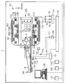
도 3은 (그 중에서도, 또한, 기술적 배경에 대해, 특히) 전신 코일(whole body coil)(102) ― 이 경우, 관형 공간(103)을 가짐 ― 을 갖는 자기 공명 이미징(MRI) 디바이스(101)(차폐된 방 또는 패러데이 케이지(Faraday cage)(F)에 위치됨)를 도시하고, 상기 관형 공간(103)에서, 이미징 방법에 의해 환자(105)의 레코딩(recording)들을 생성하기 위하여, 예컨대 검사 대상(예컨대, 환자)(105)(로컬 코일 어레인지먼트(local coil arrangement)(106)를 갖거나 또는 갖지 않음)의 바디와 함께 환자 침상(104)이 화살표(z)의 방향으로 옮겨 놓일 수 있다. 이 경우, 로컬 코일 어레인지먼트(106)는 환자 상에서 배열되고, 상기 로컬 코일 어레인지먼트에 의하여, MRI의 로컬 구역(시야 또는 FOW로 또한 지칭됨)에서, FOV에 있는 바디(105)의 일부분의 레코딩들이 생성될 수 있다. 로컬 코일 어레인지먼트(106)의 신호들은 MRI(101)의 평가 디바이스(168, 115, 117, 119, 120, 121 등등)에 의해 평가(예컨대, 이미지들로 변환, 저장 또는 디스플레이(display))될 수 있고, 상기 평가 디바이스(168, 115, 117, 119, 120, 121 등등)는 예컨대 동축 케이블(coaxial cable)들에 의하여 또는 라디오 링크(167) 등등에 의해 로컬 코일 어레인지먼트(106)에 연결될 수 있다.3 shows a magnetic resonance imaging (MRI)
자기 공명 이미징(MRI) 디바이스(101)를 이용하여, 자기 공명 이미징에 의하여 바디(105)(검사 대상 또는 환자)를 검사하기 위하여, 각자의 시간 및 공간 특성들 면에서 서로 정확하게 매칭되는 상이한 자기장들이 바디(105) 상으로 방사된다. 이 경우 터널(tunnel)-형상화된 오프닝(opening)(103)을 갖는 측정 캐빈(measurement cabin)에 있는 강한 자석(종종, 저온자석(107))이 강한 정적 주 자기장(B0)을 생성하고, 상기 주 자기장(B0)은 예컨대 0.2 테슬라(Tesla) 내지 3 테슬라 또는 그 초과의 강도를 갖는다. 검사될 바디(105)는, 환자 침상(104)에 의해 지지되면서, 관찰 구역(FoV)("시야")에서 대략 균질한 주 자기장(B0)의 구역 안으로 태워진다. 바디(105)의 원자 핵들의 핵 스핀(nuclear spin)들이, 여기서 (예컨대, 멀티-파트) 바디 코일(108)(예컨대 링들(108a, 108b, 108c) 및 길이방향 로드(rod)들(108d-108h)을 이용하여 단순화된 방식으로 묘사됨)로서 훨씬 단순화된 방식으로 묘사되는 무선주파수 안테나(및/또는, 선택적으로, 로컬 코일 어레인지먼트)에 의하여 방사되는 자기 무선주파수 여기 펄스(pulse)들 B1(x, y, z, t)에 의해 여기된다. 예로서, 무선주파수 여기 펄스들은 펄스 생성 유닛(109)에 의해 생성되고, 상기 펄스 생성 유닛(109)은 펄스 시퀀스 제어 유닛(pulse sequence control unit)(110)에 의해 제어된다. 무선주파수 증폭기(111)에 의한 증폭 이후, 상기 무선주파수 여기 펄스들은 무선주파수 안테나(108)에 안내된다. 여기서 도시된 무선주파수 시스템은 단지 개략적으로 표시된다. 자기 공명 이미징 디바이스(101)에서는, 하나보다 많은 펄스 생성 유닛(109), 하나보다 많은 무선주파수 증폭기(111) 및 여러 무선주파수 안테나들(108a, 108b, 108c)이 종종 사용된다.In order to inspect the body 105 (subject or patient) by magnetic resonance imaging using a magnetic resonance imaging (MRI)
또한, 자기 공명 이미징 디바이스(101)는 구배 코일들(112x, 112y, 112z)을 포함하고, 상기 구배 코일들(112x, 112y, 112z)에 의하여, 자기 구배 필드(field)들 BG(x, y, z, t)이 선택적 슬라이스(slice) 여기 및 측정 신호의 공간 인코딩(spatial encoding)을 위해 측정 동안 방사된다. 구배 코일들(112x, 112y, 112z)은 구배 코일 제어 유닛(114)에 의해(그리고, 선택적으로, 증폭기들(Vx, Vy, Vz)을 통해) 제어되고, 상기 구배 코일 제어 유닛(114)은, 펄스 생성 유닛(109)처럼, 펄스 시퀀스 제어 유닛(110)에 연결된다.The magnetic
(검사 대상의 원자 핵들의) 여기된 핵 스핀들에 의해 방출된 신호들이 바디 코일(108) 및/또는 적어도 하나의 로컬 코일 어레인지먼트(106)에 의해 수신되고, 연관된 무선주파수 전치증폭기들(116)에 의해 증폭되고, 수신 유닛(117)에 의해 추가로 프로세싱 및 디지털화된다. 레코딩된 측정 데이터는 k-공간 매트릭스(matrix)에서 복소수들로서 디지털화 및 저장된다. 연관된 MR 이미지는 다차원 푸리에 변환에 의한 값들로 채워진 k-공간 매트릭스로부터 재구성될 수 있다.Signals emitted by the excited nuclear spindle (of the atomic nuclei to be inspected) are received by the body coil 108 and / or the at least one
예컨대 바디 코일(108) 또는 로컬 코일(106)과 같이, 송신 모드 및 수신 모드 둘 다로 동작될 수 있는 코일에 대해, 정확한 신호 송신은 업스트림 송신/수신 스위치(118)에 의해 조절된다.For a coil that can be operated in both a transmit mode and a receive mode, such as body coil 108 or
이미지 프로세싱 유닛(119)은 측정 데이터로부터 이미지를 생성하고, 상기 이미지는 동작 콘솔(console)(120)에 의하여 사용자에게 디스플레이되거나 그리고/또는 스토리지 유닛(storage unit)(121)에 저장된다. 중앙 컴퓨터 유닛(central computer unit)(122)이 개별 설비 컴포넌트(component)들을 제어한다.The
MR 이미징에서, 요즘에는 소위 로컬 코일 어레인지먼트들(코일들, 로컬 코일들)을 이용하여 높은 신호-대-잡음비(SNR)를 갖는 이미지들이 일반적으로 레코딩된다. 이들은 바디(105) 상에(앞쪽에), 또는 바디(105) 아래에(뒤쪽에), 또는 바디(105)에, 또는 바디(105) 내에, 바로 부근에 부착되는 안테나 시스템들이다. MR 측정 동안, 여기된 핵들이 로컬 코일의 개별 안테나들에서 전압을 유도하고, 그런 다음 저-잡음 전치증폭기(예컨대, LNA, 프리앰프)를 이용하여 상기 전압이 증폭되고, 마지막으로 수신 전자장치들에 전송된다. 심지어 고 해상도 이미지들의 경우에 신호-대-잡음비를 개선시키기 위하여, 소위 하이-필드 설비들(1.5T-12T 또는 그 초과)이 사용된다. 수신기들보다 MR 수신 시스템에 연결될 수 있는 더 많은 개별 안테나들이 이용가능하다면, 예컨대 스위칭 매트릭스(RCCS로 또한 지칭됨)가 수신 안테나들과 수신기들 사이에 설치된다. 상기 매트릭스는 현재 액티브인 수신 채널들(보통, 자석의 시야에 현재 놓인 수신 채널들임)을 이용가능한 수신기들로 라우팅한다. 그 결과, 수신기들보다 이용가능한 더 많은 코일 엘리먼트들을 연결시키는 것이 가능한데, 그 이유는 전신 커버(cover)의 경우, FoV(시야)에 또는 자석의 균질한 볼륨(volume)에 위치되는 코일들만을 판독할 필요가 있기 때문이다.In MR imaging, images with a high signal-to-noise ratio (SNR) are now typically recorded using so-called local coil arrangements (coils, local coils) nowadays. These are antenna systems that are attached on the body 105 (on the front side), under the body 105 (on the back side), or on the
예로서, 예컨대 하나의 안테나 엘리먼트(antenna element)로 구성될 수 있거나 또는 여러 안테나 엘리먼트들(특히, 코일 엘리먼트들)의 어레이 코일로서 구성될 수 있는 안테나 시스템은 일반적으로 로컬 코일 어레인지먼트(106)로 지칭된다. 예로서, 이러한 개별 안테나 엘리먼트들은 루프 안테나(loop antenna)들(루프들), 버터플라이 코일(butterfly coil)들, 플렉스 코일(flex coil)들 또는 새들 코일(saddle coil)들로서 구현된다. 예로서, 로컬 코일 어레인지먼트는 코일 엘리먼트들, 전치증폭기, 추가적인 전자장치들(정상파 트랩(trap)들 등등), 하우징(housing), 지지부들, 그리고 보통 플러그(plus)를 갖는 케이블을 포함하고, 상기 케이블에 의하여, 로컬 코일 어레인지먼트가 MRI 설비에 연결된다. 설비-측에 부착된 수신기(168)가, 예컨대 라디오 링크 등등에 의해 로컬 코일(106)로부터 수신된 신호를 필터링 및 디지털화하고, 데이터를 디지털 신호 프로세싱 디바이스에 전송하며, 상기 디지털 신호 프로세싱 디바이스는 보통, 측정에 의해 획득된 데이터로부터 이미지 또는 스펙트럼을 도출하고, 예컨대 사용자에 의한 후속 진단을 위해 그리고/또는 저장하기 위해, 이것을 상기 사용자에게 이용가능하게 만든다.By way of example, an antenna system, which may be composed of, for example, one antenna element or may be configured as an array coil of various antenna elements (particularly, coil elements), is generally referred to as a
도 1-도 3은 본 발명의 예시적 실시예들의 세부사항들을 명확하게 한다.Figures 1 - 3 clarify the details of exemplary embodiments of the present invention.
핵 자기 공명에서 로컬 송신 코일 어레인지먼트들(= LC = 로컬 코일들)의 사용은 다양한 장점들을 가질 수 있다. 더 높은 B1-필드 피크(peak) 값들(B1-필드 극값들) 및/또는 더 높은 B1-필드 평균 값들을 획득하는 것이 가능하다. 특히 (아마도, 예컨대 짧은 에코 시간들과 같이) 매우 짧은 시간 기간 내에서 매우 높은 B1 값들을 요구하는 애플리케이션들(임플란트들 상에서 인공물들을 억제하기 위한 "금속 이미징", 분광학)이 더 높은 B1 피크 값들로부터 이익을 얻을 수 있다. 또한, 로컬 송신 코일 어레인지먼트들이 바디의 전용 부분(예컨대, 검사 대상의 왼쪽 무릎)에만 송신 필드를 적용하고, MRI 디바이스의 바디 코일에 위치된 (검사 대상의) 전신에 적용하지 않는다면, 상기 로컬 송신 코일 어레인지먼트들은 SAR을 제한하기 위해 장점들을 가질 수 있다. 또한, 송신 필드 및 상이한 필드 프로파일(profile)을 제한하는 것은, (예컨대, 위상 인코딩의 방향에 대해) 프로토콜을 설계할 때 장점들을 허용할 수 있는데, 그 이유는 검사되지 않을 다른 바디 부분들로부터의 컨볼루션(convolution)들이 송신 필드가 그 상에서 동작하지 않으면 더 강하게 억제될 수 있기 때문이다. 예로서, z-방향으로의 위상 인코딩 방향은, 로컬 무릎 또는 머리 코일에 의한 조사가 z-방향으로 더 낮다면, 무릎 또는 머리의 이미징 레코딩 동안 더 적은 위상 오버샘플링(oversampling)으로 때울 수 있다. 이러한 장점들은 단일 채널 및 많은 채널들 둘 다 상에서 전송하는 송신 장치의 코일들에 적용된다.The use of local transmit coil arrangements (= LC = local coils) in nuclear magnetic resonance can have a variety of advantages. It is possible to obtain higher B1-field peak values (B1-field extremes) and / or higher B1-field average values. Applications requiring very high B1 values ("metal imaging ", spectroscopy for suppressing artifacts on implants), especially in very short time periods (such as short echo times, for example) You can get a profit. Also, if the local transmit coil arrangements apply the transmit field only to a dedicated portion of the body (e.g., the left knee of the subject to be examined) and not to a body located (checked) on the body coil of the MRI device, Arrangements can have advantages to limit SAR. Also, restricting the transmission field and the different field profile may allow advantages in designing the protocol (e.g., for the direction of phase encoding) Convolutions can be more strongly suppressed if the transmit field does not operate on it. By way of example, the phase encoding direction in the z-direction can be beat with less phase oversampling during imaging recording of the knee or head if the illumination by the local knee or head coil is lower in the z-direction. These advantages apply to the coils of a transmitting apparatus transmitting on both a single channel and many channels.
그러나, 로컬 송신 코일들의 사용으로부터 단점이 나올 수 있다: 로컬 코일로부터의 로컬로 강하게 제한된, 그리고 아마도 살짝 더 비균질한 송신 필드를 이용하여, 모든 타입들의 검사들이 반드시 잘 동작하는 것은 아니다.However, there may be drawbacks from the use of local transmit coils: using locally strongly restricted and possibly slightly inhomogeneous transmit fields from local coils, not all types of checks necessarily work well.
예로서, 로컬 송신 코일을 이용하여, 머리 검사 다음에, 경추 검사가 수행될 것이라면, 코일은 교환될 수 있고, 환자의 위치가 바뀔 수 있다.By way of example, using a local transmit coil, following a head examination, if a cervical examination is to be performed, the coil can be exchanged and the position of the patient can be changed.
로컬 송신 코일들의 장점들은 다음을 포함한다:Advantages of local transmit coils include:
- 더 높은 B1 피크,- higher B1 peak,
- 더 낮은 글로벌 SAR,- Lower global SAR,
- 바디 코일(BC)보다, 송신 코일(TX)이 검사될 조직으로부터 살짝 더 멀리 배치되기가 더 쉽다면, 더 낮은 로컬 SAR(바디 코일의 경우, 이것은 값비쌀 수 있는 자석 지름의 손상에 대한 것일 수 있음), If the transmit coil TX is easier to locate slightly farther away from the tissue to be inspected than for the body coil BC then a lower local SAR (in the case of a body coil, Lt; / RTI >
- 더 편리한 프로토콜 선택을 위한 필드 프로파일들의 더 강한 로컬화, 또는 송신(TX) 프로파일(PTX)들의 개선된 직교성.- stronger localization of field profiles for more convenient protocol selection, or improved orthogonality of transmit (TX) profiles (PTX).
여기서 문제점은, 현재 로컬 송신 코일들 ― 상기 현재 로컬 송신 코일들이 시스템에 연결된다면 ― 이 송신 코일들로서 배타적으로 사용되어야 하고, 안전 이유들로(BC 및 LC의 유도성 커플링(inductive coupling)에 의한 환자 화상들을 방지하기 위해, 그리고 BC로부터의 필드의 로컬 송신 코일에 의한 포커싱을 위해), 송신 코일 어레인지먼트로서 로컬 TX 코일의 존재시 MRI 디바이스의 바디 코일(BC)을 이용한 송신이 허용되지 않아야 한다는 점일 수 있다. 알려져 있는 한, 소위 유도성으로 커플링된 송신 코일들("Inductive Coupled Local TX Coil Design"(Wang, Vester 등등))만이 현재, 특별한 역할을 맡는다. 여기서, 로컬 송신 코일에는 케이블에 의하여 송신 전력이 공급되는 것이 아니라, 그보다는 상기 로컬 송신 코일에는 바디 코일(BC)에 의해 유도성으로 전력이 공급된다. 여기서 타겟(target)된 그리고 정확하게 계량된 방식으로, 필드 포커싱 ― 그렇지 않으면 원해지지 않음 ― 이 사용된다. 그러나, 알려져 있는 한, 코일의 존재시, 더 큰 코일(BC)을 이용한 송신을 허용하고 "원해지지 않는" 코일을 디튜닝(detuning)하고 그에 따라 하나의 송신 코일 또는 다른 하나의 송신 코일의 선택을 허용하는 모드는, 송신 코일의 어느 쪽 타입(케이블 연결된 또는 유도성으로 커플링된)에 대해서도 현재 제공되지 않는다.The problem here is that the current local transmit coils - if the current local transmit coils are connected to the system - should be used exclusively as transmit coils and for safety reasons (by inductive coupling of BC and LC) (For focusing by the local transmit coil of the field from the BC and to prevent patient images), transmission using the body coil BC of the MRI device in the presence of the local TX coil as transmit coil arrangement should not be allowed . As far as is known, only so-called inductively coupled transmit coils ("Inductive Coupled Local TX Coil Design" (Wang, Vester, etc.)) now play a special role. Here, not the transmission power is supplied to the local transmission coil by the cable, but rather the power is inductively supplied to the local transmission coil by the body coil BC. Field focusing, otherwise not desired, is used here in a targeted and precisely metered manner. However, as far as is known, in the presence of a coil, it is possible to detuning the coil that is not "unwanted" while allowing transmission using a larger coil BC and thus to select one transmit coil or another transmit coil Is not currently provided for either type of transmission coil (either cabled or inductively coupled).
MRI 시스템의 제어 유닛에 의하여, MRI 디바이스의 바디 코일(BC) 또는 MRI 디바이스의 로컬 TX 코일을 이용하여 송신이 교대로 유발될 수 있는 코일 어레인지먼트들이 지금까지 구현되지 않았다. 이것의 결과로서, 하나의 검사/시퀀스 타입(예컨대, 순수한 머리 이미징)에 대해 로컬 송신 코일의 장점들이 사용될 수 있고, (예컨대, 그 후) 환자의 위치가 그동안에 바뀔 필요 없이, (예컨대, 경추 이미징을 위해) 비교적 큰 구역들이 바디 코일(BC)에 의하여 조사될 수 있다. 그러한 코일 어레인지먼트, 연관된 회로 아키텍처(circuit architecture)들, 작동 및 검사 진행은, 함께 또는 개별 토픽(topic)들로서, 본 발명의 구성들의 논제들이다.Coil arrangements in which transmissions can be alternately induced using the body coil (BC) of the MRI device or the local TX coil of the MRI device by the control unit of the MRI system have not been implemented so far. As a result of this, the advantages of the local transmit coil can be used for one test / sequence type (e.g., pure head imaging), and the position of the patient (e.g., Relatively large areas may be irradiated by the body coil BC for imaging. Such coil arrangements, associated circuit architectures, operation and inspection progress are topics of the inventive arrangements, either together or as individual topics.
코일 어레인지먼트들:Coil Arrangements:
예로서, 도 1 또는 도 3에서, 두 개의 송신 코일 어레인지먼트들(104, 106)이 MRI 시스템(101)에 위치된다. 여기서, 하나의 송신 코일 어레인지먼트(예컨대, 로컬 코일(LC)(106))가 더 큰 송신 코일 어레인지먼트(예컨대, 바디 코일(BC)(104)) 내에 위치될 수 있거나, 또는 이것이 MRI 디바이스(101)에서 상이한 위치들에 있는, 예컨대 유사한 치수들의 두 개의 송신 코일 어레인지먼트들에 관련될 수 있다. 디튜닝 회로들((예컨대 PIN 다이오드(diode)들과 같은) 스위치(switch)들에 의해 스위칭되는 예컨대 공명 회로들)에 의하여, 송신 코일 어레인지먼트들 둘 다가 교대로 또는 동시에 (송신 목적들을 위해, 공명하도록) 튜닝되거나 또는 (다른 하나의 송신 코일 어레인지먼트가 전송할 때 그리고 그 반대일 때, 하나의 송신 코일 어레인지먼트의 원해지지 않는 공명을 방지하기 위해) 디튜닝되는 것이 가능하다. 여기서, 디튜닝 회로들은, 하나의 송신 코일 어레인지먼트가 추가적인 송신 코일 어레인지먼트에서 유도할 수 있는 고전압들이 디튜닝(의 충분한 효과)에서의 강하를 이끌 수 없도록 설계될 수 있다.By way of example, in FIG. 1 or FIG. 3, two
디튜닝을 위한 가능한 회로 아키텍처들은 다음과 같을 수 있다:The possible circuit architectures for detuning may be as follows:
- 솔루션 1: 송신 코일 어레인지먼트들은, 와이어들(TX-K1, TX-K2, TX-K3, TX-K4)에 의해 적용되는 상대적으로 고전압(이를 위한 통상적 전압들: 50-500V)에 의해 디튜닝될 수 있다.Solution 1: The transmit coil arrangements are detuned by a relatively high voltage applied by wires (TX-K1, TX-K2, TX-K3, TX-K4) .
- 솔루션 2: 송신 코일 어레인지먼트들은 상대적으로 저전압(이를 위한 통상적 전압들: 1-50V)에 의해 프리-디튜닝될 수 있다. 그런 다음, 예컨대 (PIN 다이오드) 스위치들을 디튜닝하기에 적절한 (전술된) 고전압(특히, DC 전압)이 예컨대 정류기 회로에 의해 생성되고, 상기 정류기 회로는 예컨대 송신 코일 어레인지먼트로부터 유도성으로 커플링된 교류 RF 필드로부터 그 전압을 획득한다.Solution 2: The transmit coil arrangements can be pre-detuned by a relatively low voltage (typical voltages for this: 1-50 V). A high voltage (in particular a DC voltage) suitable for detuning (PIN diode) switches, for example (described above), is then generated, for example, by a rectifier circuit, which is inductively coupled, for example from a transmit coil arrangement And obtains the voltage from the AC RF field.
안전 이유들로, (부수적으로 또한, 부가적인 수신 코일들을 포함할 수 있거나 또는 수신을 위해 송신 코일들을 사용할 수 있는) 송신 코일 어레인지먼트는 유리하게도 ― 그러나, 반드시는 아님 ―, (예컨대 연결부가 부주의로 제거되었기 때문에) 커넥터들이 MRI 디바이스(101) 안으로 (예컨대, 그 환자 침상에 있는 커넥터들을 통해) 삽입되지 않는다면, 상기 송신 코일 어레인지먼트가 RF 송신 필드에 의하여 자신을 디튜닝하도록(즉, 상기 송신 코일 어레인지먼트가 자신을 패시브하게 디튜닝하도록) 구현될 수 있다; 디튜닝 회로들은, 외부 공급부에 의하여 전압/전류 소스를 적용함으로써만 스위칭되고, 코일 어레인지먼트는 공명하게 되고, 송신 목적들을 위해 사용될 수 있다.For safety reasons, transmit coil arrangements (which, incidentally, may also include additional receive coils or use transmit coils for reception) are advantageously - but not necessarily - If the connectors are not inserted into the MRI device 101 (e.g., through connectors on the patient bed), the transmission coil arrangement may be detuned by the RF transmit field (i.e., the transmit coil arrangement To passively detune itself); The detuning circuits are switched only by applying a voltage / current source by an external supply, the coil arrangement becomes resonant, and can be used for transmission purposes.
자기 공명 이미징 시스템의 송신 장치(109)에 의해 RF 송신 코일 어레인지먼트들(104; 106)을 작동시킬 때, RF 전원을 위한 회로 아키텍처들:Circuit architectures for RF power supply when operating RF transmit coil arrangements 104 (106) by a
제1 솔루션 1이 (도 1에서 TX-K1, TX-K2, TX-K3, TX-K4와 같은) 케이블들을 통해 RF 펄스들(RF-P1 - RF-P8)을 이용하여 공급부에 놓일 수 있다.The
제2 솔루션 2가 (예컨대, 패시브하게) 유도성으로 커플링된 전력에 의하여 공급부에 놓일 수 있다.And the second solution 2 may be placed in the supply by inductively coupled power (e.g., passively).
예로서, 검사 진행이 다음과 같을 수 있다:As an example, the inspection progress may be as follows:
추가적인 송신 코일 어레인지먼트들(106, 104)의 존재시 하나의 송신 코일 어레인지먼트(104, 106)를 이용한 송신 그리고 그 반대는, 심지어 둘 다가 서로 강하게 커플링되더라도, 가능하다.The transmission with one transmit
예로서, 바디 코일(= BC)(104) 형태의 송신 코일 어레인지먼트가 검사 대상의 개요 이미지를 생성하는데 사용될 수 있고, 그런 다음 로컬 코일(106) 형태의 로컬 송신 코일 어레인지먼트가 단지 더욱 로컬인 검사를 위해 사용될 수 있다.By way of example, a transmit coil arrangement in the form of a body coil (= BC) 104 can be used to generate an overview image of the object to be inspected, and then the local transmit coil arrangement in the form of
또는, 예컨대, 머리 송신 코일을 이용하여 머리 검사들이 이루어질 수 있고, 바디 코일(104)을 이용하여 척추(예컨대, 경추) 검사들이 이루어질 수 있다.Alternatively, head examinations may be made using, for example, a head transmit coil, and vertebrae (e.g., cervical vertebra) tests may be performed using the
또는, 예컨대, 목에 있는 혈액의 로컬 여기가 존재할 수 있고(동맥 스핀 라벨링(arterial spin labeling)), 목 송신 코일에 의하여, 머리에서, 라벨링된 혈액의 이미징이 존재할 수 있고, 그 뒤에 바디 코일(104)을 이용한 (종래의) 머리 검사가 이어질 수 있다.Or, for example, a local excitation of blood in the neck may be present (arterial spin labeling) and imaging of the labeled blood may be present at the head, by the neck transmission coil, followed by the body coil 104 (conventional) head inspection can be followed.
이러한 검사들 전부는 ― 환자/코일들을 바꾸는 것 없이 ― 적절한 작동 및 디튜닝 개념들에 의해서만 또한 구현될 수 있다.All of these tests can also be implemented by appropriate operating and detuning concepts - without changing patient / coils.
지금까지, 디튜닝을 위한 그리고 전력을 공급하기 위한 전술된 솔루션들에 대한 몇몇 회로들은, 이와 같이, 적어도 내부적으로 알려진 종래 기술이다. 이 점에서, 추가적인 RF 송신 코일 어레인지먼트(들)의 존재시 RF 송신 코일 어레인지먼트들 중 하나를 이용한 송신, 그리고 그 반대가 허용되고 가능하게 되도록, (RF) 송신 코일 어레인지먼트들 및 그 작동의 결합이 신규하고, 디튜닝된 송신 코일 어레인지먼트로부터 환자로의 위험도 존재하지 않고 현재 전송하는 송신 코일 어레인지먼트의 송신 필드가 크게 왜곡되지도 않도록 디튜닝이 치수화된다.So far, some circuits for the above-described solutions for detuning and powering are thus known at least in the prior art. In this regard, the combination of (RF) transmit coil arrangements and their operation is described in terms of a novel, novel transmission coil arrangement, such that transmission with one of the RF transmit coil arrangements in the presence of additional RF transmit coil arrangement (s) Detuning is dimensioned so that there is no risk from the detuned transmission coil arrangement to the patient and the transmission field of the currently transmitted transmission coil arrangement is not significantly distorted.
여기서, 코일 어레인지먼트들은 상이한 조사 볼륨들 및 필드 프로파일들을 갖고, 정확하게는, 이러한 차이는, 코일 교환/환자의 위치 바뀜과 같은 단점들 없이 전술된 장점들을 활용하는데 사용될 수 있다.Here, the coil arrangements have different irradiation volumes and field profiles, and precisely, this difference can be used to exploit the advantages described above without disadvantages such as coil exchange / patient position changes.
또한, 하나의 검사/시퀀스로부터 다음 차례로, 하나의 송신 코일 어레인지먼트로부터 추가적인 송신 코일 어레인지먼트로 송신의 스위칭이 존재하는 것뿐만 아니라, 두 개의 코일 어레인지먼트 타입들 사이의 매우 신속한 스위칭(예컨대 10 마이크로초 내지 100㎳의 사이클(cycle) 시간을 가짐)이 미래의 애플리케이션들에 원해질 수 있음도 고려될 수 있다. 이는, 어느 송신 코일 어레인지먼트가 송신 펄스별로 그리고 뿐만 아니라 하나의 시퀀스 타입으로부터 다음 차례로 전송하는지의 선택을 허용하는 MRI 디바이스(101)의 제어 유닛(107) 때문에 가능해질 수 있다.In addition, there is also a very fast switching between two coil array types (e.g., from 10 microseconds to 100 microseconds), as well as the presence of switching of transmissions from one transmit coil arrangement to additional transmit coil arrangements in the next order from one check / Lt; RTI ID = 0.0 > msec < / RTI > cycle time) may be desired for future applications. This may be possible because of the
매우 특별한 애플리케이션들에 대해 양쪽 코일들의 서로로부터의 가능한 디커플링은 편파 디커플링일 것이다: 코일들은 예컨대 상호 직교 편파 방향들로 전송한다(예컨대, 바디 코일(104)은 수직 편파만을 갖고, 로컬 코일(106)은 수평 편파만을 가짐); 선택적으로, 이는, 애플리케이션들 중 몇몇에만 적용될 수 있는데, 그 이유는 이것이 (예컨대, SAR에 관련된) 다른 단점들을 숨길 수 있기 때문이다.The possible decoupling of both coils from each other for very specific applications would be polarization decoupling: the coils transmit, for example, in mutually orthogonal polarization directions (e.g.,
본 발명의 단계는, 상이한 애플리케이션들에 대해 TX 조사 및 그 TX 필드 프로파일들이 각각의 경우 코일-특정 장점들(더 높은 B1 피크, 더 큰 FoV, 더 균질한 B1 프로파일 등등)을 갖도록, 두 개 또는 두 개보다 많은 전송하는 송신 코일 어레인지먼트들(선택적으로, 서로 강하게 유도성으로 커플링됨)을 배열하는 것으로 구성될 수 있다. 이러한 장점들은, 추가적인 코일 어레인지먼트(106, 104)의 존재시 전송하는 송신 코일 어레인지먼트(104, 106)를 이용한 송신(그리고 그 반대)이 가능하도록, 그리고 각각의 경우 전송하는 송신 코일 어레인지먼트의 사용되지 않는 (디튜닝된) 코일로부터 환자(105)로의 위험이 존재하지 않도록, 그리고 다른 하나의 전송하는 송신 코일 어레인지먼트(106, 104)의 필드 프로파일에 원해지지 않는 영향이 끼쳐지지 않도록, MRI 디바이스(101)의 로컬 코일들(106)이 치수화 및 작동될 수 있는 것 때문에 사용가능해질 수 있다. 그 결과, 로컬로 전송하는 송신 코일 어레인지먼트(106)(그러나, 특히, 또한 N=I-X개 송신 채널들 및 M=1-Y개 수신 채널들을 갖는 하이브리드 코일)를 더 큰, 전송하는 송신 코일 어레인지먼트(예컨대, BC(104))의 송신 필드에 남겨 두는 것이 가능하고, 각각의 검사에 대해 최선 특징들만을 갖는 검사를 위해 상기 전송하는 송신 코일 어레인지먼트(106/104)를 사용하는 것이 가능하다.The steps of the present invention are based on the assumption that the TX lookup and its TX field profiles for the different applications have two or more values such that each has coil-specific advantages (higher B1 peak, larger FoV, more homogeneous B1 profile, etc.) And may be arranged to arrange more than two transmitting transmitting coil arrangements (optionally, strongly inductively coupled to one another). These advantages are advantageous in that transmission (and vice versa) is possible with the transmitting
상세하게, 도 1은 ((예컨대 도 2의 RF-P1 - RF-P4와 같은) RF 펄스들 및 RF 송신 전력을 전송하기 위한) 송신 케이블들(TX-K1, TX-K2, TX-K3)을 통해 제어 유닛(109)(그 내에 RF 펄스들을 생성하기 위한 송신기를 가짐)에 연결된 MRI 디바이스(101)의 복수의 (RF) 전송하는 송신 코일 어레인지먼트(104, 106)를 단순화된 방식으로 도시하고, 상기 송신 코일들은 (예컨대 도 2에 도시된 것들과 같은) RF 펄스들을 전송하기 위한 제어 유닛(107)에 의해 각각 작동될 수 있다.In particular, Figure 1 illustrates transmission cables (TX-K1, TX-K2, TX-K3) (to transmit RF pulses and RF transmit power (e.g., RF-P1 - RF- (RF) transmitting
도 1은 복수의 안테나들(108a, 108b, 108c, 108d, 108b, 108f, 108g, 108h)을 포함하는 바디 코일(=바디코일=BC)(104) 형태의 RF 송신 코일 어레인지먼트, 그리고 복수의 안테나들(예컨대, 어레이로서 구현됨)(TX1, TX2, TX3 등등)(임의의 형태 및 어레인지먼트로 있음)을 포함하고 아마도 자신만의 수신 안테나들(RX)을 포함하는 로컬 코일(106) 형태의 RF 송신 코일 어레인지먼트를 묘사하고, 여기서 안테나들(TX1, TX2, TX3 등등)은 개별적으로 교대로 작동될 수 있거나 그리고/또는 그 중 여러 개가 RF 펄스들을 전송하기 위해 함께/동시에 작동될 수 있다.1 shows an RF transmit coil arrangement in the form of a body coil (= body coil = BC) 104 including a plurality of
RF 송신 코일 어레인지먼트들(BC = 104; 106)은 서로 유도성으로 커플링될 수 있거나, 또는 이들을 디커플링하는 것이 가능할 수 있다.The RF transmit coil arrangements (BC = 104; 106) may be inductively coupled to each other, or it may be possible to decouple them.
예로서, 임의의 주어진 시간(t)에서, 송신 장치(109)(송신기를 가짐)가 RF 펄스들을 전송하기 위해 RF 송신 코일 어레인지먼트들(104, 106) 중 하나만을 항상 작동시키는 동시에, 다른 하나의 RF 송신 코일 어레인지먼트(106, 104)는 바람직하게, 특히 특정 주파수를 갖는 RF 펄스들로 (액티브하게 그리고/또는 패시브하게) 디튜닝된다.By way of example, at any given time t, the transmitting device 109 (with the transmitter) always operates only one of the RF transmit
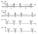
상세하게, 도 2는, 예로서, 제어 및 송신 장치(109)가 임의의 주어진 시간(t)에, RF 펄스들을 전송하기 위해, 로컬 코일(106) 형태의 단 한 개의 RF 송신 코일 어레인지먼트(BC = 104; 106)이든 또는 바디 코일(104) 형태의 단 한 개의 RF 송신 코일 어레인지먼트이든 어떻게 작동시키는지를 도시한다.In detail, FIG. 2 illustrates, by way of example, only one RF transmit coil arrangement (BC) in the form of a
상단으로부터 제1 라인에서, 도 2는, 인가되는 전압의 레벨에 따라, 바디 코일(104)을 Utune으로 튜닝하거나(공명으로) 또는 바디 코일(104)을 Udetune으로 디튜닝하기 위하여, 시간(t)에 걸쳐, 시간들(t1, t2, t3, t4)에서, 바디 코일(104) 형태의 RF 송신 코일 어레인지먼트에 (패시브하게 그리고/또는 예컨대 제어 유닛(107)에 의하여) 인가되는 (DC) 전압들(Utune, Udetune)(또는 전류들)을 묘사한다.In the first line from the top, FIG. 2 shows the time (t) of the
상단으로부터 제2 라인에서, 도 2는, 인가되는 전압의 레벨에 따라, 상기 바디 코일(104)을 Utune으로 튜닝하거나(공명으로) 또는 상기 바디 코일(104)을 Udetune으로 디튜닝하기 위하여, 시간(t)에 걸쳐, 시간들(t5, t6, t7, t8)에서, 바디 코일(104) 형태의 RF 송신 코일 어레인지먼트에 (필드에 의하여 패시브하게 그리고/또는 예컨대 제어 유닛(107)에 의하여 액티브하게) 인가되는 (DC) 전압들(Utune, Udetune)(또는 전류들)을 묘사한다.In the second line from the top, Fig. 2 shows the time (in resonance) of the
상단으로부터 제3 라인에서, 도 2는, 시간(t)에 걸쳐, 시간들(t1, t2, t3, t4)에서, 방출된 RF 펄스들(RF-P1, RF-P2, RF-P3, RF-P4)의, 바디 코일(104) 형태의 하나의 RF 송신 코일 어레인지먼트로부터의 펄스 전력 진폭들(P)(104)을 묘사한다.In the third line from the top, Fig. 2 shows the emission of RF pulses RF-P1, RF-P2, RF-P3, and RF at time t1, t2, t3, t4 over time t (P) 104 from one RF transmit coil arrangement in the form of a
상단으로부터 제4 라인에서, 도 2는, 시간(t)에 걸쳐, 시간들(t5, t6, t7, t8)에서, 방출된 RF 펄스들(RF-P5, RF-P6, RF-P7, RF-P8)의, 바디 코일(106) 형태의 하나의 RF 송신 코일 어레인지먼트로부터의 펄스 전력 진폭들(P)(106)을 묘사한다. 예로서, 시간 간격들의 예들은 예컨대 (RF 펄스들의) 시퀀스 내에서 I1 = 0.01 내지 10,000㎳이거나 그리고/또는 두 개의 시퀀스들 사이에서 I2 = 1㎳ 내지 600초이다.
P5, RF-P6, RF-P7, and RF at time t5, t6, t7, t8, (P) 106 from one RF transmit coil arrangement in the form of a
Claims (27)
상기 자기 공명 이미징 시스템(101)은 적어도 두 개의 RF 송신 코일 어레인지먼트(transmission coil arrangement)들(104; 106) ― 각각은 적어도 하나의 RF 송신 안테나(transmission antenna)(108a-108h; TX1, TX2, TX3)를 가짐 ― 을 포함하고,
상기 RF 송신 코일 어레인지먼트들(104, 106)은 RF 펄스(pulse)들(RF-P1 - RF-P8)을 전송하기 위해 상기 자기 공명 이미징 시스템(101)의 송신 장치(109)에 의해 작동될 수 있는,
자기 공명 이미징 시스템(101).A magnetic resonance imaging system (101) comprising:
The MR imaging system 101 comprises at least two RF transmission coil arrangements 104 106 each having at least one RF transmission antenna 108a-108h, TX1, TX2, TX3 ), ≪ / RTI >
The RF transmit coil arrangements 104 and 106 may be operated by a transmitting device 109 of the magnetic resonance imaging system 101 to transmit RF pulses RF-P1 - RF- there is,
Magnetic resonance imaging system (101).
상기 자기 공명 이미징 시스템(101)은 적어도 두 개의 RF 송신 코일 어레인지먼트들(BC = 104; 106) ― 각각은 적어도 하나의 RF 송신 안테나(108a-108c; TX1, TX2, TX3)를 가짐 ― 을 포함하고,
상기 RF 송신 코일 어레인지먼트들(104, 106)은, 송신 목적들을 위해, 혼자서만 교대로든지 그리고/또는 그 복수 개가 함께 동시에든지, 송신 장치(송신기(109))에 의해 작동될 수 있는,
자기 공명 이미징 시스템(101).The method according to claim 1,
The magnetic resonance imaging system 101 comprises at least two RF transmit coil arrangements (BC = 104; 106) each having at least one RF transmit antenna 108a-108c (TX1, TX2, TX3) ,
The RF transmit coil arrangements 104, 106 may be used for transmission purposes, either alone alone and / or multiple thereof together at the same time, or may be operated by a transmitting device (transmitter 109)
Magnetic resonance imaging system (101).
상기 RF 송신 코일 어레인지먼트들(BC = 104; 106)은 서로 유도성으로 커플링(coupling)되는,
자기 공명 이미징 시스템(101).3. The method according to claim 1 or 2,
The RF transmit coil arrangements (BC = 104; 106) are inductively coupled to one another,
Magnetic resonance imaging system (101).
송신 장치(송신기(109))는, 특히 환자의 변경된 포지션 없이 그리고/또는 상기 RF 송신 코일 어레인지먼트들(BC = 104; 106)의 변경된 포지션 없이, 특히 상이한 애플리케이션들에 대해, 상이한 공간 TX 조사를 위해 그리고/또는 시간-가변적인 TX 필드 프로파일(field profile)들에 대해, 상기 RF 송신 코일 어레인지먼트들(BC = 104; 106)을 작동시키도록 구현되는,
자기 공명 이미징 시스템(101).4. The method according to any one of claims 1 to 3,
The transmitting device (transmitter 109) may be configured for different spatial TX probing, especially for different applications, without changing the position of the patient and / or with the altered position of the RF transmit coil arrangements (BC = 104; 106) And / or for time-varying TX field profiles, to implement the RF transmit coil arrangements (BC = 104; 106)
Magnetic resonance imaging system (101).
송신 장치(송신기(109))는, 임의의 주어진 시간에, RF 펄스들(RF-P1 - RF-P4; RF-P5 - RF-P8)을 전송하기 위해, 상기 RF 송신 코일 어레인지먼트들(BC = 104; 106) 중 하나만이 항상 작동되도록 구현되는,
자기 공명 이미징 시스템(101).5. The method according to any one of claims 1 to 4,
The transmitter (transmitter 109) is configured to transmit the RF transmit coil arrangements (BC = < RTI ID = 0.0 > 104, < RTI ID = 0.0 > 106 < / RTI &
Magnetic resonance imaging system (101).
송신 장치(송신기(109))는, 임의의 주어진 시간(t)에, RF 펄스들(RF-P1 - RF-P4; RF-P5 - RF-P8)을 전송하기 위해, 상기 RF 송신 코일 어레인지먼트들(104; 106) 중 하나만이 항상 작동되고 다른 하나는 특히 RF 펄스들(RF-P1 - RF-P8)에 대해 디튜닝(detuning)되도록 구현되는,
자기 공명 이미징 시스템(101).6. The method according to any one of claims 1 to 5,
The transmitter (transmitter 109) is configured to transmit RF pulses RF-P1-RF-P4, RF-P5-RF-P8 at any given time t, Only one of the RF pulses 104 (106) is always active and the other is implemented to be detuned especially for RF pulses (RF-P1-RF-P8)
Magnetic resonance imaging system (101).
상기 자기 공명 이미징 시스템(101)은, 이 경우 RF 송신 코일 어레인지먼트(104; 106)를 디튜닝하기 위한 전류가 다른 하나의 RF 송신 코일 어레인지먼트(106; 104)의 송신 필드로부터 정류에 의해 완전히 또는 부분적으로 생성될 수 있도록 구현되는,
자기 공명 이미징 시스템(101).7. The method according to any one of claims 1 to 6,
The magnetic resonance imaging system 101 is configured such that the current for detuning the RF transmit coil arrangement 104 106 in this case is completely or partially received by rectification from the transmit field of one of the other RF transmit coil arrangements 106, Lt; RTI ID = 0.0 >
Magnetic resonance imaging system (101).
송신 장치(109)는, 이미징 검사를 위해, 검사에 대해 더 나은 특징들을 갖는 RF 송신 코일 어레인지먼트(104; 106)만이 송신 목적들을 위해 사용되도록 구현되는,
자기 공명 이미징 시스템(101).8. The method according to any one of claims 1 to 7,
The transmitting device 109 is configured for use only for transmitting purposes, for imaging inspection, only an RF transmit coil arrangement 104 (106) with better characteristics for the test,
Magnetic resonance imaging system (101).
상기 RF 송신 코일 어레인지먼트들(104; 106) 중 하나는 로컬 코일(106)이고, 다른 하나의 RF 송신 코일 어레인지먼트(104; 106)는 전신 코일(104)인,
자기 공명 이미징 시스템(101).9. The method according to any one of claims 1 to 8,
One of the RF transmit coil arrangements 104 106 is a local coil 106 and the other RF transmit coil arrangement 104 106 is a full body coil 104,
Magnetic resonance imaging system (101).
송신 장치(송신기(109))는, 임의의 주어진 시간(t)에, 상기 송신 장치(송신기(109))가 송신 목적들을 위해 작동되는, 로컬 코일(106) 형태의 단 한 개의 RF 송신 코일 어레인지먼트(104; 106)이거나 또는 전신 코일(104) 형태의 단 한 개의 RF 송신 코일 어레인지먼트(104; 106)이도록 구현되는,
자기 공명 이미징 시스템(101).10. The method according to any one of claims 1 to 9,
A transmitter (transmitter 109) may be configured to transmit only one RF transmit coil arrangement in the form of a local coil 106, which transmitter (transmitter 109) is operated for transmit purposes at any given time t. (104; 106), or only one RF transmit coil arrangement (104; 106) in the form of a full body coil (104)
Magnetic resonance imaging system (101).
송신 장치(109)는, 환자(105)의 구역(K, ROI)의 제1 이미징 검사를 위해, 로컬 코일(106) 형태의 단 한 개의 RF 송신 코일 어레인지먼트(104; 106)만이 RF 펄스들(RF-P5, RF-P6, RF-P7, RF-P8)을 전송하기 위해 특정 시간들(t5, t6, t7, t8)에 작동되도록, 그리고 추가적인 시간들(t1, t2, t3, t4)에서 환자(105)의 특히 추가적인 구역(B)의 시간상 그 이후 또는 그 이전에 이루어지는 추가적인 이미징 검사를 위해, 전신 코일(104) 형태의 단 한 개의 RF 송신 코일 어레인지먼트(104; 106)만이 RF 펄스들(RF-P1, RF-P2, RF-P3, RF-P4)을 전송하기 위해 작동되도록 구현되는, (도 2)
자기 공명 이미징 시스템(101).11. The method according to any one of claims 1 to 10,
The transmitting device 109 is configured such that only a single RF transmit coil arrangement 104 (106) in the form of a local coil 106 is required for RF pulses (R, T2, t3, t4) to be activated at specific times t5, t6, t7, t8 to transmit RF-P5, RF-P6, RF- Only one RF transmit coil arrangement 104 (106) in the form of a full-body coil 104 is required to provide RF pulses (< RTI ID = 0.0 > (FIG. 2), which is implemented to operate to transmit RF-P1, RF-P2, RF-P3,
Magnetic resonance imaging system (101).
상기 RF 송신 코일 어레인지먼트들 중 하나(106)는 상기 RF 송신 코일 어레인지먼트들 중 다른 하나(104) 내에 위치되는,
자기 공명 이미징 시스템(101).12. The method according to any one of claims 1 to 11,
One of the RF transmit coil arrangements being located within the other one of the RF transmit coil arrays,
Magnetic resonance imaging system (101).
상기 RF 송신 코일 어레인지먼트들(104; 106) 중 두 개가 각각, 또는 각각의 RF 송신 코일 어레인지먼트가 로컬 코일(106)인,
자기 공명 이미징 시스템(101).13. The method according to any one of claims 1 to 12,
Wherein each of the two RF transmit coil arrangements (104; 106), or each RF transmit coil arrangement is a local coil (106)
Magnetic resonance imaging system (101).
상기 RF 송신 코일 어레인지먼트들(104; 106) 중 한 개 또는 두 개가 각각, 또는 각각의 RF 송신 코일 어레인지먼트가 디튜닝 회로(detuning circuit), 특히 공명 회로 및/또는 스위치(switch)들, 특히 PIN 다이오드(diode)들을 갖는 디튜닝 회로에 연결되거나 또는 연결될 수 있는,
자기 공명 이미징 시스템(101).14. The method according to any one of claims 1 to 13,
One or both of the RF transmit coil arrangements 104 and 106, respectively, or each RF transmit coil arrangement may be coupled to a detuning circuit, particularly a resonant circuit and / or switches, which can be connected to or coupled to a detuning circuit having diodes,
Magnetic resonance imaging system (101).
RF 송신 코일 어레인지먼트들(104; 106)을 디튜닝하기 위한 디튜닝 회로들은 유선 연결부(TX-K1 내지 TX-K3)에 의하여 그에 인가되는 50-500V의 전압에 의해 디튜닝될 수 있는,
자기 공명 이미징 시스템(101).15. The method according to any one of claims 1 to 14,
The detuning circuits for detuning RF transmit coil arrangements 104 (106) may be detuned by a voltage of 50-500V applied thereto by wired connections (TX-K1 to TX-K3)
Magnetic resonance imaging system (101).
RF 송신 코일 어레인지먼트들(104; 106)을 디튜닝하기 위한 디튜닝 회로들은 유선 연결부(TX-K1 내지 TX-K3)에 의하여 그에 인가되는 1 V-50V의 전압을 공급받을 수 있고,
그에 인가될 수 있는 부가적인 전압, 특히 DC 전압은 PIN 다이오드 스위치들을 디튜닝하기 위한 정류기 회로에 의해 생성될 수 있고, 상기 정류기 회로의 전압은 상기 RF 송신 코일 어레인지먼트들(104; 106) 중 적어도 하나의 유도성으로 커플링된 교류 RF 필드로부터 획득될 수 있는,
자기 공명 이미징 시스템(101).16. The method according to any one of claims 1 to 15,
Detuning circuits for detuning RF transmit coil arrangements 104 (106) may be supplied with a voltage of 1 V-50 V applied thereto by wire connections (TX-K1 to TX-K3)
An additional voltage that may be applied thereto, in particular a DC voltage, may be generated by a rectifier circuit for detuning PIN diode switches, wherein the voltage of the rectifier circuit is at least one of the RF transmit coil arrangements (104; 106) Lt; RTI ID = 0.0 > RF < / RTI &
Magnetic resonance imaging system (101).
상기 RF 송신 코일 어레인지먼트들(104; 106) 중 적어도 하나의 RF 송신 코일 어레인지먼트는, 그 연결 플러그(plug)들이 환자 테이블(table) 및/또는 MRI 디바이스(device)(104)에 연결되지 않을 때, 상기 적어도 하나의 RF 송신 코일 어레인지먼트가 추가적인 RF 송신 코일 어레인지먼트들(106; 104)로부터의 RF 펄스들(RF-P1 - RF-P4; RF-P5 - RF-P8)에 의해 유도되는 전압들 및/또는 전류들을 이용하여 자신을 디튜닝하도록 치수화되는,
자기 공명 이미징 시스템(101).17. The method according to any one of claims 1 to 16,
At least one RF transmit coil arrangement of the RF transmit coil arrangements 104 and 106 is configured such that when the connection plugs are not connected to the patient table and / or the MRI device 104, Wherein the at least one RF transmit coil arrangement is adapted to receive voltages induced by RF pulses RF-P1-RF-P4; RF-P5-RF-P8 from additional RF transmit coil arrangements 106; Or are dimensioned to detune itself using currents,
Magnetic resonance imaging system (101).
외부 공급부에 의한 전압원 및/또는 전류원을 적용함으로써, 상기 RF 송신 코일 어레인지먼트들(104; 106) 중 하나를 각각 디튜닝하거나 그리고/또는 상기 RF 송신 코일 어레인지먼트들(106; 104) 중 하나가 공명되도록 각각 스위칭하기 위하여, 디튜닝 회로들은 RF 송신 코일 어레인지먼트(104; 106)로 연결될 수 있는,
자기 공명 이미징 시스템(101).18. The method according to any one of claims 1 to 17,
By applying a voltage source and / or a current source by an external supply, each of the RF transmit coil arrangements 104 (106) and / or one of the RF transmit coil arrays 106 (104) For switching respectively, the detuning circuits may be connected to the RF transmit coil arrangement 104 (106)
Magnetic resonance imaging system (101).
MRI 디바이스(101)의 제어 유닛(109, 110)은, 적어도 하나의 추가적인 RF 송신 코일 어레인지먼트(106; 104)가 상기 MRI 디바이스(101)에 존재하는 동안, 상기 RF 송신 코일 어레인지먼트들(104; 106) 중 하나의 RF 송신 코일 어레인지먼트로부터의 송신을 가능케 하는,
자기 공명 이미징 시스템(101).19. The method according to any one of claims 1 to 18,
A control unit (109,110) of the MRI device (101) is configured to control the RF transmit coil arrangements (104; 106; 104) while at least one additional RF transmit coil arrangement Lt; RTI ID = 0.0 > RF < / RTI > transmission coil arrangement,
Magnetic resonance imaging system (101).
MRI 디바이스(101)는, 검사 대상(105)의 이미징 검사 이후 그리고/또는 다음 차례의 이미징 검사에 앞서 시퀀스 이후, 상기 RF 송신 코일 어레인지먼트들(104; 106) 중 하나의 RF 송신 코일 어레인지먼트에 의한 송신으로부터 상기 RF 송신 코일 어레인지먼트들(104; 106) 중 추가적인 RF 송신 코일 어레인지먼트로 자동 스위칭이 존재하도록 구현되는,
자기 공명 이미징 시스템(101).20. The method according to any one of claims 1 to 19,
The MRI device 101 may be configured to transmit a transmission by one of the RF transmit coil arrangements 104 106 after an imaging check of the object of inspection 105 and / To an additional RF transmit coil arrangement of the RF transmit coil arrangements (104; 106)
Magnetic resonance imaging system (101).
MRI 디바이스(101)는, 검사 대상(105)의 이미징 검사 및/또는 시퀀스 동안, 10㎲-100㎳의 사이클(cycle) 시간을 이용하여, 상기 RF 송신 코일 어레인지먼트들(104; 106) 중 하나의 RF 송신 코일 어레인지먼트에 의한 송신으로부터 상기 RF 송신 코일 어레인지먼트들(104; 106) 중 추가적인 RF 송신 코일 어레인지먼트로 자동 스위칭이 존재하도록 구현되는,
자기 공명 이미징 시스템(101).21. The method according to any one of claims 1 to 20,
The MRI device 101 may be configured to measure one of the RF transmit coil arrangements 104 and 106 using a cycle time of 10 占 퐏 to 100 ms during imaging inspection and / Wherein there is automatic switching from transmission by RF transmit coil arrangement to additional RF transmit coil arrangement among the RF transmit coil arrangements (104; 106)
Magnetic resonance imaging system (101).
MRI 디바이스(101)는, 상기 MRI 디바이스(101)의 제어 유닛(110, 109)이 각각의 경우 상기 RF 펄스들(RF-P1 - RF-P4) 중 하나의 송신 펄스에 대해 상기 RF 송신 코일 어레인지먼트들 중 하나의 RF 송신 코일 어레인지먼트(104)의 선택을 가능케 하고, 차례로 상기 RF 펄스들(RF-P5 - RF-P8) 중 후속 송신 펄스들 중 하나 또는 그 초과에 대해 상기 RF 송신 코일 어레인지먼트들 중 다른 하나의 RF 송신 코일 어레인지먼트(106)의 선택을 가능케 하도록 구현되는,
자기 공명 이미징 시스템(101).22. The method according to any one of claims 1 to 21,
The MRI device 101 may be configured such that the control units 110 and 109 of the MRI device 101 are each capable of transmitting the RF transmit coil arrangement for one of the RF pulses RF- (RF-P5-RF-P8) of one of the RF transmit coil arrangements for one or more of the subsequent transmit pulses of the RF pulses (RF-P5-RF-P8) Is implemented to enable selection of the other RF transmit coil arrangement (106)
Magnetic resonance imaging system (101).
상기 RF 송신 코일 어레인지먼트들(104; 106) 중 하나의 RF 송신 코일 어레인지먼트는 편파 디커플링에 의해 상기 RF 송신 코일 어레인지먼트들(104; 106) 중 추가적인 RF 송신 코일 어레인지먼트로부터 디커플링될 수 있는,
자기 공명 이미징 시스템(101).23. The method according to any one of claims 1 to 22,
The RF transmit coil arrangement of one of the RF transmit coil arrangements 104 106 may be decoupled from additional RF transmit coil arrangements of the RF transmit coil arrangements 104 106 by polarization decoupling,
Magnetic resonance imaging system (101).
상기 RF 송신 코일 어레인지먼트들(104; 106)은, 특히 수직 편파로만 전송하는 RF 송신 코일 어레인지먼트(104) 및 수평 편파로만 전송하는 추가적인 RF 송신 코일 어레인지먼트(106)를 이용하여, 상호 직교 편파 방향들로 전송 및/또는 수신하도록 구현되는,
자기 공명 이미징 시스템(101).24. The method according to any one of claims 1 to 23,
The RF transmit coil arrangements 104 and 106 may be arranged in mutually orthogonal polarization directions using an RF transmit coil arrangement 104 that transmits only vertically polarized waves and an additional RF transmit coil arrangement 106 that transmits only horizontally polarized waves. And / or < / RTI >
Magnetic resonance imaging system (101).
두 개의 RF 송신 코일 어레인지먼트들(104; 106)은 비-전도성 방식으로 서로 연결되거나, 그리고/또는 서로 전기적으로 절연되는,
자기 공명 이미징 시스템(101).25. The method according to any one of claims 1 to 24,
The two RF transmit coil arrangements (104; 106) are connected to each other in a non-conductive manner, and / or electrically insulated from each other,
Magnetic resonance imaging system (101).
적어도 두 개의 RF 송신 코일 어레인지먼트들(104; 106) 중에서 ― 각각은 적어도 하나의 RF 송신 안테나(108a-108c; TX1, TX2, TX3)를 가짐 ―, 각각의 경우(t), RF 펄스들(RF-P1 - RF-P4; RF-P5 - RF-P8)을 전송하기 위해, 상기 자기 공명 이미징 시스템(101)의 송신 장치(109)에 의해 단 한 개만이 작동되는,
방법.25. A method for MRI imaging using a magnetic resonance imaging system (101) according to any one of claims 1 to 25,
Each of the at least two RF transmit coil arrangements 104-106 has at least one RF transmit antenna 108a-108c (TX1, TX2, TX3) Only one is operated by the transmitting device 109 of the magnetic resonance imaging system 101 to transmit the RF-P5-RF-P4 (RF-P5-RF-P8)
Way.
환자(105)의 구역(K, ROI)의 제1 이미징 검사를 위해, 제1 시간들(t5, t6, t7, t8)에서, 송신 장치(109)는, RF 펄스들(RF-P5, RF-P6, RF-P7, RF-P8)을 전송하기 위해, 로컬 코일(106) 형태의 하나의 RF 송신 코일 어레인지먼트만을 작동시키고, 그리고 시간상 그 이후 또는 그 이전에 이루어지는 추가적인 시간들(t1, t2, t3, t4)에서 환자(105)의 특히 추가적인 구역(B)의 추가적인 이미징 검사를 위해, 상기 송신 장치(109)는, RF 펄스들(RF-P1, RF-P2, RF-P3, RF-P4)을 전송하기 위해, 전신 코일(104) 형태의 하나의 RF 송신 코일 어레인지먼트만을 작동시키고,
동시에, 바람직하게, 각각의 경우 현재 전송하지 않는 RF 송신 코일 어레인지먼트(104; 106)는 전압 및/또는 전류에 의해 디커플링(Udetune)되거나 그리고/또는 비-공명적이 되도록 스위칭되는,
방법.
27. The method of claim 26,
At a first time (t5, t6, t7, t8), the transmitting device 109 transmits RF pulses RF-P5, RF Only one RF transmit coil arrangement in the form of a local coil 106 is activated and the additional times (t1, t2, ..., P1, RF-P2, RF-P3, RF-P4, and RF-P4 for additional imaging examination of the patient 105, Only one RF transmit coil arrangement in the form of a full body coil 104 is activated,
At the same time, preferably, the RF transmission coil arrangement 104 (106), which in each case is not currently transmitting, is switched to be Udetune and / or non-resonant by voltage and /
Way.
Applications Claiming Priority (2)
| Application Number | Priority Date | Filing Date | Title |
|---|---|---|---|
| DE102013214285.4A DE102013214285A1 (en) | 2013-07-22 | 2013-07-22 | Use of multiple TX coils |
| DE102013214285.4 | 2013-07-22 |
Publications (1)
| Publication Number | Publication Date |
|---|---|
| KR20150011325A true KR20150011325A (en) | 2015-01-30 |
Family
ID=52131417
Family Applications (1)
| Application Number | Title | Priority Date | Filing Date |
|---|---|---|---|
| KR20140091814A KR20150011325A (en) | 2013-07-22 | 2014-07-21 | Use of a plurality of tx coils |
Country Status (5)
| Country | Link |
|---|---|
| US (1) | US10274560B2 (en) |
| JP (1) | JP6463608B2 (en) |
| KR (1) | KR20150011325A (en) |
| CN (1) | CN104330756B (en) |
| DE (1) | DE102013214285A1 (en) |
Families Citing this family (9)
| Publication number | Priority date | Publication date | Assignee | Title |
|---|---|---|---|---|
| US8970217B1 (en) | 2010-04-14 | 2015-03-03 | Hypres, Inc. | System and method for noise reduction in magnetic resonance imaging |
| CN105143905B (en) * | 2013-04-23 | 2019-05-10 | 皇家飞利浦有限公司 | Single coaxial interface for magnetic resonance (MR) coil |
| DE102014202567B4 (en) * | 2014-02-12 | 2017-05-04 | Siemens Healthcare Gmbh | Method for generating magnetic resonance imaging and magnetic resonance tomography system |
| DE102014209783B4 (en) * | 2014-05-22 | 2018-06-14 | Siemens Healthcare Gmbh | Creating an MR image using a combination of a whole-body coil and a local transmitter coil |
| EP3248024B1 (en) * | 2015-01-21 | 2024-04-03 | Koninklijke Philips N.V. | Automated impedance adjustment of a multichannel rf coil assembly |
| CN106646298B (en) * | 2015-10-28 | 2019-05-24 | 西门子(深圳)磁共振有限公司 | A kind of body coil and magnetic resonance imaging system |
| JP6687375B2 (en) * | 2015-11-30 | 2020-04-22 | キヤノンメディカルシステムズ株式会社 | RF coil and magnetic resonance imaging apparatus |
| EP3581954B1 (en) * | 2018-06-12 | 2023-03-08 | Siemens Healthcare GmbH | Sensor and magnetic resonance tomographic device with wireless near-field transmission of power and data |
| EP4016103A1 (en) * | 2020-12-18 | 2022-06-22 | Siemens Healthcare GmbH | Magnetic resonance tomograph and method for rapidly switching from tx to rx |
Family Cites Families (26)
| Publication number | Priority date | Publication date | Assignee | Title |
|---|---|---|---|---|
| FI73320C (en) | 1984-01-20 | 1987-09-10 | Instrumentarium Oy | NMR SPOLARRANGEMANG. |
| JPH0194834A (en) * | 1987-10-06 | 1989-04-13 | Mitsubishi Electric Corp | High frequency probe for nmr and nmr signal measuring method |
| US5243287A (en) * | 1992-04-27 | 1993-09-07 | General Electric Company | Dynamically detuned NMR field coil |
| DE10051155C2 (en) | 2000-10-16 | 2002-09-19 | Siemens Ag | Inherently decoupled MR receiving coil arrangement |
| DE10113661A1 (en) * | 2001-03-21 | 2002-09-26 | Philips Corp Intellectual Pty | Catheter for magnetic resonance imaging has an excitation transmitter at its distal end which excites vibration within the area surrounding it that is readily imaged by the MR imaging device |
| US6552544B2 (en) | 2001-04-05 | 2003-04-22 | Varian, Inc. | Detunable coil assembly and method of detuning RF coil for MRI |
| WO2003098247A1 (en) * | 2002-05-15 | 2003-11-27 | Siemens Aktiengesellschaft | Magnetic resonance system |
| US6850067B1 (en) * | 2002-05-17 | 2005-02-01 | General Electric Company | Transmit mode coil detuning for MRI systems |
| DE10314215B4 (en) | 2003-03-28 | 2006-11-16 | Siemens Ag | Magnetic resonance antenna and method for detuning their natural resonance frequency |
| DE102006046044B4 (en) * | 2006-09-28 | 2010-04-08 | Siemens Ag | High-frequency transmission arrangement of a magnetic resonance system |
| EP2147325A1 (en) * | 2007-05-04 | 2010-01-27 | Koninklijke Philips Electronics N.V. | Method and rf transmitter arrangement for generating rf fields |
| JP5405017B2 (en) * | 2007-12-28 | 2014-02-05 | ジーイー・メディカル・システムズ・グローバル・テクノロジー・カンパニー・エルエルシー | Coil system and MRI apparatus |
| DE102008014751B4 (en) | 2008-03-18 | 2015-01-15 | Siemens Aktiengesellschaft | Method for operating an arrangement for detuning a receiving antenna in a local coil |
| CN101782635A (en) * | 2009-01-20 | 2010-07-21 | 西门子迈迪特(深圳)磁共振有限公司 | Receiver and receiving method of magnetic resonance signal |
| DE102009012109B4 (en) * | 2009-03-06 | 2011-05-12 | Siemens Aktiengesellschaft | Digital method for channel reduction in MR receiving systems and corresponding device |
| DE102009052197B4 (en) | 2009-11-06 | 2013-06-13 | Siemens Aktiengesellschaft | MR signal transmission in a local coil arrangement |
| WO2011065532A1 (en) * | 2009-11-30 | 2011-06-03 | 株式会社 日立メディコ | High-frequency coil unit and magnetic resonance imaging device |
| US9081066B2 (en) * | 2010-03-24 | 2015-07-14 | Hoby P. Hetherington | Method and apparatus for generating an effective equivalent of simultaneous transmission to a targeted tissue using a conventional transceiver array |
| DE102010020153A1 (en) | 2010-05-11 | 2011-11-17 | Siemens Aktiengesellschaft | Combinable multi-part surface coil for magnetic resonance tomography |
| US8269499B2 (en) * | 2010-06-01 | 2012-09-18 | Quality Electrodynamics, Llc | Failsafe protection from induced RF current for MRI RF coil assembly having transmit functionality |
| DE102010025919A1 (en) | 2010-07-02 | 2012-01-05 | Siemens Aktiengesellschaft | Magnetic resonance imaging system has coil system with upper section and lower section, where upper section is arranged above opening for inclusion of object under examination |
| JP2012239723A (en) * | 2011-05-20 | 2012-12-10 | Toshiba Corp | Magnetic resonance imaging apparatus |
| CN103703384B (en) | 2011-07-20 | 2016-12-14 | 皇家飞利浦有限公司 | For the local parallel transmitting coil inductively of MRI, its element each include variableimpedance |
| US9645207B2 (en) | 2011-09-28 | 2017-05-09 | General Electric Company | Adjustable MRI head coil apparatus and MRI system |
| DE102011083959B4 (en) * | 2011-10-04 | 2021-02-25 | Siemens Healthcare Gmbh | Method for controlling a magnetic resonance system |
| US8918159B2 (en) * | 2012-04-18 | 2014-12-23 | Mayo Foundation For Medical Education And Research | System and method for improved accelerated magnetic resonance imaging using ROI masking |
-
2013
- 2013-07-22 DE DE102013214285.4A patent/DE102013214285A1/en not_active Ceased
-
2014
- 2014-07-18 JP JP2014147643A patent/JP6463608B2/en active Active
- 2014-07-21 US US14/337,199 patent/US10274560B2/en not_active Expired - Fee Related
- 2014-07-21 KR KR20140091814A patent/KR20150011325A/en not_active Application Discontinuation
- 2014-07-22 CN CN201410350075.2A patent/CN104330756B/en active Active
Also Published As
| Publication number | Publication date |
|---|---|
| US20150022208A1 (en) | 2015-01-22 |
| US10274560B2 (en) | 2019-04-30 |
| CN104330756B (en) | 2018-06-08 |
| JP2015020075A (en) | 2015-02-02 |
| DE102013214285A1 (en) | 2015-01-22 |
| JP6463608B2 (en) | 2019-02-06 |
| CN104330756A (en) | 2015-02-04 |
Similar Documents
| Publication | Publication Date | Title |
|---|---|---|
| US10274560B2 (en) | Use of a plurality of TX coils | |
| US9851423B2 (en) | Patient-adaptive B0 homogenization of MR systems using different types of shim coils | |
| KR101615880B1 (en) | Local coil, especially neck coil, with a number of separately switchable local coil shim coils | |
| US20100102817A1 (en) | Hybrid birdcage-tem radio frequency (rf) coil for multinuclear mri/mrs | |
| KR101645199B1 (en) | Automatic detuning of non-connected transceiver coils for mri | |
| JP2015020075A5 (en) | ||
| US9864023B2 (en) | Combined shim and RF coil arrangement | |
| US9547055B2 (en) | Identifying the static position of transmission/reception coils of a magnetic resonance imaging scanner with the aid of electronically readable labels | |
| US10509085B2 (en) | Automated impedance adjustment of a multichannel RF coil assembly | |
| US9448295B2 (en) | Multi-layer cushion for optimum adjustment to anatomy and for susceptibility adjustment | |
| US20150025362A1 (en) | Local Transmission Coils and Transmission Coil Arrays for Spinal Column Imaging in an MRI Device | |
| US9726470B2 (en) | Identifying a position of transmission/reception coils of a magnetic resonance imaging scanner with labels read in motion | |
| US9903897B2 (en) | Identifying transmission/reception coils of a magnetic resonance imaging scanner with the aid of electronically readable labels | |
| CN106872921B (en) | MR imaging method and device | |
| KR101959405B1 (en) | Combined hf/shim/gradient signal routing | |
| US10031193B2 (en) | Local SAR behavior of MRI transmission coils by use of orthogonal loop antennas | |
| US20140073909A1 (en) | MR Patient Couch with Integrated RF Devices | |
| CN105044633B (en) | Knee coil | |
| KR101661453B1 (en) | Holder for double loop coil | |
| US9671476B2 (en) | Application of a multichannel coil for hand imaging | |
| US20130123612A1 (en) | Mrt surface coil array | |
| JP4236595B2 (en) | Magnetic resonance imaging system |
Legal Events
| Date | Code | Title | Description |
|---|---|---|---|
| WITN | Application deemed withdrawn, e.g. because no request for examination was filed or no examination fee was paid |