KR20140147834A - Integrated implant - Google Patents
Integrated implant Download PDFInfo
- Publication number
- KR20140147834A KR20140147834A KR1020147028547A KR20147028547A KR20140147834A KR 20140147834 A KR20140147834 A KR 20140147834A KR 1020147028547 A KR1020147028547 A KR 1020147028547A KR 20147028547 A KR20147028547 A KR 20147028547A KR 20140147834 A KR20140147834 A KR 20140147834A
- Authority
- KR
- South Korea
- Prior art keywords
- implant
- bone
- cutting
- integral
- distal end
- Prior art date
Links
Images


Classifications
-
- A—HUMAN NECESSITIES
- A61—MEDICAL OR VETERINARY SCIENCE; HYGIENE
- A61B—DIAGNOSIS; SURGERY; IDENTIFICATION
- A61B17/00—Surgical instruments, devices or methods, e.g. tourniquets
- A61B17/16—Bone cutting, breaking or removal means other than saws, e.g. Osteoclasts; Drills or chisels for bones; Trepans
-
- A—HUMAN NECESSITIES
- A61—MEDICAL OR VETERINARY SCIENCE; HYGIENE
- A61B—DIAGNOSIS; SURGERY; IDENTIFICATION
- A61B17/00—Surgical instruments, devices or methods, e.g. tourniquets
- A61B17/56—Surgical instruments or methods for treatment of bones or joints; Devices specially adapted therefor
- A61B17/58—Surgical instruments or methods for treatment of bones or joints; Devices specially adapted therefor for osteosynthesis, e.g. bone plates, screws, setting implements or the like
- A61B17/68—Internal fixation devices, including fasteners and spinal fixators, even if a part thereof projects from the skin
- A61B17/84—Fasteners therefor or fasteners being internal fixation devices
- A61B17/846—Nails or pins, i.e. anchors without movable parts, holding by friction only, with or without structured surface
-
- A—HUMAN NECESSITIES
- A61—MEDICAL OR VETERINARY SCIENCE; HYGIENE
- A61F—FILTERS IMPLANTABLE INTO BLOOD VESSELS; PROSTHESES; DEVICES PROVIDING PATENCY TO, OR PREVENTING COLLAPSING OF, TUBULAR STRUCTURES OF THE BODY, e.g. STENTS; ORTHOPAEDIC, NURSING OR CONTRACEPTIVE DEVICES; FOMENTATION; TREATMENT OR PROTECTION OF EYES OR EARS; BANDAGES, DRESSINGS OR ABSORBENT PADS; FIRST-AID KITS
- A61F2/00—Filters implantable into blood vessels; Prostheses, i.e. artificial substitutes or replacements for parts of the body; Appliances for connecting them with the body; Devices providing patency to, or preventing collapsing of, tubular structures of the body, e.g. stents
- A61F2/02—Prostheses implantable into the body
- A61F2/30—Joints
- A61F2/30988—Other joints not covered by any of the groups A61F2/32 - A61F2/4425
-
- A—HUMAN NECESSITIES
- A61—MEDICAL OR VETERINARY SCIENCE; HYGIENE
- A61B—DIAGNOSIS; SURGERY; IDENTIFICATION
- A61B17/00—Surgical instruments, devices or methods, e.g. tourniquets
- A61B17/16—Bone cutting, breaking or removal means other than saws, e.g. Osteoclasts; Drills or chisels for bones; Trepans
- A61B17/1662—Bone cutting, breaking or removal means other than saws, e.g. Osteoclasts; Drills or chisels for bones; Trepans for particular parts of the body
- A61B17/1671—Bone cutting, breaking or removal means other than saws, e.g. Osteoclasts; Drills or chisels for bones; Trepans for particular parts of the body for the spine
-
- A—HUMAN NECESSITIES
- A61—MEDICAL OR VETERINARY SCIENCE; HYGIENE
- A61B—DIAGNOSIS; SURGERY; IDENTIFICATION
- A61B17/00—Surgical instruments, devices or methods, e.g. tourniquets
- A61B17/56—Surgical instruments or methods for treatment of bones or joints; Devices specially adapted therefor
- A61B17/58—Surgical instruments or methods for treatment of bones or joints; Devices specially adapted therefor for osteosynthesis, e.g. bone plates, screws, setting implements or the like
- A61B17/68—Internal fixation devices, including fasteners and spinal fixators, even if a part thereof projects from the skin
- A61B17/70—Spinal positioners or stabilisers ; Bone stabilisers comprising fluid filler in an implant
- A61B17/7055—Spinal positioners or stabilisers ; Bone stabilisers comprising fluid filler in an implant connected to sacrum, pelvis or skull
-
- A—HUMAN NECESSITIES
- A61—MEDICAL OR VETERINARY SCIENCE; HYGIENE
- A61F—FILTERS IMPLANTABLE INTO BLOOD VESSELS; PROSTHESES; DEVICES PROVIDING PATENCY TO, OR PREVENTING COLLAPSING OF, TUBULAR STRUCTURES OF THE BODY, e.g. STENTS; ORTHOPAEDIC, NURSING OR CONTRACEPTIVE DEVICES; FOMENTATION; TREATMENT OR PROTECTION OF EYES OR EARS; BANDAGES, DRESSINGS OR ABSORBENT PADS; FIRST-AID KITS
- A61F2/00—Filters implantable into blood vessels; Prostheses, i.e. artificial substitutes or replacements for parts of the body; Appliances for connecting them with the body; Devices providing patency to, or preventing collapsing of, tubular structures of the body, e.g. stents
- A61F2/02—Prostheses implantable into the body
- A61F2/28—Bones
-
- A—HUMAN NECESSITIES
- A61—MEDICAL OR VETERINARY SCIENCE; HYGIENE
- A61F—FILTERS IMPLANTABLE INTO BLOOD VESSELS; PROSTHESES; DEVICES PROVIDING PATENCY TO, OR PREVENTING COLLAPSING OF, TUBULAR STRUCTURES OF THE BODY, e.g. STENTS; ORTHOPAEDIC, NURSING OR CONTRACEPTIVE DEVICES; FOMENTATION; TREATMENT OR PROTECTION OF EYES OR EARS; BANDAGES, DRESSINGS OR ABSORBENT PADS; FIRST-AID KITS
- A61F2/00—Filters implantable into blood vessels; Prostheses, i.e. artificial substitutes or replacements for parts of the body; Appliances for connecting them with the body; Devices providing patency to, or preventing collapsing of, tubular structures of the body, e.g. stents
- A61F2/02—Prostheses implantable into the body
- A61F2/30—Joints
- A61F2/44—Joints for the spine, e.g. vertebrae, spinal discs
- A61F2/4455—Joints for the spine, e.g. vertebrae, spinal discs for the fusion of spinal bodies, e.g. intervertebral fusion of adjacent spinal bodies, e.g. fusion cages
-
- A—HUMAN NECESSITIES
- A61—MEDICAL OR VETERINARY SCIENCE; HYGIENE
- A61F—FILTERS IMPLANTABLE INTO BLOOD VESSELS; PROSTHESES; DEVICES PROVIDING PATENCY TO, OR PREVENTING COLLAPSING OF, TUBULAR STRUCTURES OF THE BODY, e.g. STENTS; ORTHOPAEDIC, NURSING OR CONTRACEPTIVE DEVICES; FOMENTATION; TREATMENT OR PROTECTION OF EYES OR EARS; BANDAGES, DRESSINGS OR ABSORBENT PADS; FIRST-AID KITS
- A61F2/00—Filters implantable into blood vessels; Prostheses, i.e. artificial substitutes or replacements for parts of the body; Appliances for connecting them with the body; Devices providing patency to, or preventing collapsing of, tubular structures of the body, e.g. stents
- A61F2/02—Prostheses implantable into the body
- A61F2/30—Joints
- A61F2/46—Special tools or methods for implanting or extracting artificial joints, accessories, bone grafts or substitutes, or particular adaptations therefor
- A61F2/4603—Special tools or methods for implanting or extracting artificial joints, accessories, bone grafts or substitutes, or particular adaptations therefor for insertion or extraction of endoprosthetic joints or of accessories thereof
- A61F2/4611—Special tools or methods for implanting or extracting artificial joints, accessories, bone grafts or substitutes, or particular adaptations therefor for insertion or extraction of endoprosthetic joints or of accessories thereof of spinal prostheses
-
- A—HUMAN NECESSITIES
- A61—MEDICAL OR VETERINARY SCIENCE; HYGIENE
- A61B—DIAGNOSIS; SURGERY; IDENTIFICATION
- A61B17/00—Surgical instruments, devices or methods, e.g. tourniquets
- A61B17/064—Surgical staples, i.e. penetrating the tissue
- A61B17/0642—Surgical staples, i.e. penetrating the tissue for bones, e.g. for osteosynthesis or connecting tendon to bone
-
- A—HUMAN NECESSITIES
- A61—MEDICAL OR VETERINARY SCIENCE; HYGIENE
- A61F—FILTERS IMPLANTABLE INTO BLOOD VESSELS; PROSTHESES; DEVICES PROVIDING PATENCY TO, OR PREVENTING COLLAPSING OF, TUBULAR STRUCTURES OF THE BODY, e.g. STENTS; ORTHOPAEDIC, NURSING OR CONTRACEPTIVE DEVICES; FOMENTATION; TREATMENT OR PROTECTION OF EYES OR EARS; BANDAGES, DRESSINGS OR ABSORBENT PADS; FIRST-AID KITS
- A61F2/00—Filters implantable into blood vessels; Prostheses, i.e. artificial substitutes or replacements for parts of the body; Appliances for connecting them with the body; Devices providing patency to, or preventing collapsing of, tubular structures of the body, e.g. stents
- A61F2/02—Prostheses implantable into the body
- A61F2/30—Joints
- A61F2/30988—Other joints not covered by any of the groups A61F2/32 - A61F2/4425
- A61F2002/30995—Other joints not covered by any of the groups A61F2/32 - A61F2/4425 for sacro-iliac joints
-
- A—HUMAN NECESSITIES
- A61—MEDICAL OR VETERINARY SCIENCE; HYGIENE
- A61F—FILTERS IMPLANTABLE INTO BLOOD VESSELS; PROSTHESES; DEVICES PROVIDING PATENCY TO, OR PREVENTING COLLAPSING OF, TUBULAR STRUCTURES OF THE BODY, e.g. STENTS; ORTHOPAEDIC, NURSING OR CONTRACEPTIVE DEVICES; FOMENTATION; TREATMENT OR PROTECTION OF EYES OR EARS; BANDAGES, DRESSINGS OR ABSORBENT PADS; FIRST-AID KITS
- A61F2/00—Filters implantable into blood vessels; Prostheses, i.e. artificial substitutes or replacements for parts of the body; Appliances for connecting them with the body; Devices providing patency to, or preventing collapsing of, tubular structures of the body, e.g. stents
- A61F2/02—Prostheses implantable into the body
- A61F2/30—Joints
- A61F2/44—Joints for the spine, e.g. vertebrae, spinal discs
- A61F2002/448—Joints for the spine, e.g. vertebrae, spinal discs comprising multiple adjacent spinal implants within the same intervertebral space or within the same vertebra, e.g. comprising two adjacent spinal implants
-
- A—HUMAN NECESSITIES
- A61—MEDICAL OR VETERINARY SCIENCE; HYGIENE
- A61F—FILTERS IMPLANTABLE INTO BLOOD VESSELS; PROSTHESES; DEVICES PROVIDING PATENCY TO, OR PREVENTING COLLAPSING OF, TUBULAR STRUCTURES OF THE BODY, e.g. STENTS; ORTHOPAEDIC, NURSING OR CONTRACEPTIVE DEVICES; FOMENTATION; TREATMENT OR PROTECTION OF EYES OR EARS; BANDAGES, DRESSINGS OR ABSORBENT PADS; FIRST-AID KITS
- A61F2/00—Filters implantable into blood vessels; Prostheses, i.e. artificial substitutes or replacements for parts of the body; Appliances for connecting them with the body; Devices providing patency to, or preventing collapsing of, tubular structures of the body, e.g. stents
- A61F2/02—Prostheses implantable into the body
- A61F2/30—Joints
- A61F2/46—Special tools or methods for implanting or extracting artificial joints, accessories, bone grafts or substitutes, or particular adaptations therefor
- A61F2/4603—Special tools or methods for implanting or extracting artificial joints, accessories, bone grafts or substitutes, or particular adaptations therefor for insertion or extraction of endoprosthetic joints or of accessories thereof
- A61F2002/4625—Special tools or methods for implanting or extracting artificial joints, accessories, bone grafts or substitutes, or particular adaptations therefor for insertion or extraction of endoprosthetic joints or of accessories thereof with relative movement between parts of the instrument during use
- A61F2002/4627—Special tools or methods for implanting or extracting artificial joints, accessories, bone grafts or substitutes, or particular adaptations therefor for insertion or extraction of endoprosthetic joints or of accessories thereof with relative movement between parts of the instrument during use with linear motion along or rotating motion about the instrument axis or the implantation direction, e.g. telescopic, along a guiding rod, screwing inside the instrument
Landscapes
- Health & Medical Sciences (AREA)
- Orthopedic Medicine & Surgery (AREA)
- Life Sciences & Earth Sciences (AREA)
- Surgery (AREA)
- Biomedical Technology (AREA)
- Engineering & Computer Science (AREA)
- Animal Behavior & Ethology (AREA)
- General Health & Medical Sciences (AREA)
- Heart & Thoracic Surgery (AREA)
- Veterinary Medicine (AREA)
- Public Health (AREA)
- Neurology (AREA)
- Molecular Biology (AREA)
- Nuclear Medicine, Radiotherapy & Molecular Imaging (AREA)
- Medical Informatics (AREA)
- Oral & Maxillofacial Surgery (AREA)
- Transplantation (AREA)
- Cardiology (AREA)
- Vascular Medicine (AREA)
- Dentistry (AREA)
- Neurosurgery (AREA)
- Physical Education & Sports Medicine (AREA)
- Prostheses (AREA)
- Surgical Instruments (AREA)
Abstract
일체형 커팅 브로치 및/또는 커팅 버를 가지는 임플란트가 개시된다. 일체형 임플란트는 뼈를 천공하고 브로칭하기 위한 개별 단계들을 요구하지 않으면서 삽입될 수 있다. 일체형 임플란트 조립체는 일체형 임플란트, 가요성 덮개, 전달 봉, 및 전달 핀을 포함할 수 있다. 임플란트는 다양한 횡단면의 기하학적 형상들 중 어느 하나를 가질 수 있는 코어를 가질 수 있다. 뼈 유합 방법은 임플란트를 측면에서 장골을 관통하여, 천장-관절을 관통하여, 천골 내로 삽입하는 단계를 포함할 수 있다.An implant having an integral cutting broach and / or a cutting bur is disclosed. Integral implants can be inserted without requiring separate steps to perforate and broach the bone. The integral implant assembly may include an integral implant, a flexible lid, a delivery rod, and a delivery pin. The implant may have a core that can have any of a variety of cross-sectional geometric shapes. The bone union method may include the step of inserting the implant through the ilium at the side, through the ceiling-joint, and into the sacrum.
Description
관련 출원에 대한 교차 출원Cross-Application for Related Application
본 특허 출원은 2012년 3월 9일에 출원되고 발명의 명칭이 "일체형 임플란트"인 미국 가 출원 제 61/609,221호를 우선권으로 청구한다. 이 특허 출원은 아래의 특허 출원들 중 하나 또는 그 초과의 특허 출원과 관련될 수 있다: 2010년 10월 5일에 출원되고 발명의 명칭이 "천골-장골 관절의 유합을 위한 시스템 및 방법"인 미국 특허 공보 제 2011/0087294호 및 2010년 12월 6일에 출원되고 발명의 명칭이 "전방 추체 간 유합을 위한 장치, 시스템들, 및 방법들"인 미국 특허 공보 제 2011/0118785호. 이 인용문헌들 각각은 본 명세서에서 전체가 인용에 의해 포함된다.
This patent application claims priority from U.S. Provisional Application No. 61 / 609,221, filed March 9, 2012, entitled "Integrated Implant ". This patent application may relate to one or more of the following patent applications: A patent application, filed October 5, 2010, entitled " System and Method for Union of the Sacrum - U.S. Patent Publication No. 2011/0087294 and U.S. Patent Application Publication No. 2011/0118785, filed on December 6, 2010, entitled "Apparatus, systems, and methods for anterior interbody fusion". Each of these cited documents is incorporated herein by reference in its entirety.
인용에 의한 포함 관계(INCORPORATION BY REFERENCE)INCORPORATION BY REFERENCE
본 명세서에서 언급된 모든 공보들 및 특허 출원들은, 각각의 개별 공보 또는 특허 출원이 인용에 의해 특별히 그리고 개별적으로 포함되는 것으로 표시된 것과 동일한 정도로, 인용에 의해 본 명세서에 포함된다.
All publications and patent applications mentioned in this specification are herein incorporated by reference to the same extent as if each individual publication or patent application was specifically and individually indicated to be incorporated by reference.
분야Field
본 발명은 일반적으로 뼈의 고정 또는 유합(fusion)에 관한 것이다.
The present invention generally relates to the fixation or fusion of bones.
많은 유형의 하드웨어가 골절되는 뼈들의 고정 및 유합될 뼈들의 고정 양자 모두에 대해 이용가능하다. 유합은 보통 관절에 의해 분리된 두 개의 뼈들이 하나의 뼈로 함께 성장하는 것을 허용하는 작업이다. 이러한 유형의 유합 처치(fusion procedure)에 대한 의학적 용어는 관절 고정술(arthrodesis)이다.
Many types of hardware are available for both the fixation of the fractured bone and the fixation of the bone to be united. Union is a task that allows two bones separated by joints to grow together into one bone. The medical term for this type of fusion procedure is arthrodesis.
예를 들면, 허리 유합 처치(lumbar fusion procedure)들은 등 아래 부분에서의 퇴행성 변화들의 영향들 및 통증의 치료에서 사용되어 왔다. 허리 유합의 일 예는 척추의 S1-L5-L4 영역에서의 유합이다.
For example, lumbar fusion procedures have been used in the treatment of pain and the effects of degenerative changes in the lower back. An example of a waist union is fusion in the S1-L5-L4 region of the vertebra.
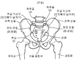
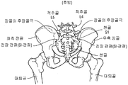
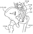
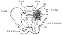
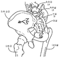
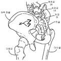
다른 예, 사람의 골반대(hip girdle)(도 9 및 도 10 참조)는 두 개의 상대적으로 움직이지 않는 관절들에 의해 연결된 3개의 큰 뼈들로 이루어진다. 이 뼈들 중 하나는 천골이라 불리고 이 뼈는 요추골의 바닥에 놓이며 여기서 이 뼈는 L5 척추골과 연결된다. 나머지 두 개의 뼈들은 통상적으로 "골반뼈들"이라 불리고 기술적으로 우측 장골 및 좌측 장골로 지칭된다. 천골은 좌측 및 우측 천장 관절(간단히, SI-관절)에서 양 골반뼈들과 연결된다.
Another example, the hip girdle of a human (see Figures 9 and 10), consists of three large bones connected by two relatively immobile joints. One of these bones is called the sacrum, which is placed on the floor of the lumbar spine where it connects with the L5 vertebra. The other two bones are commonly referred to as "pelvic bones ", technically referred to as right iliac and left iliac. The sacrum is connected to both pelvic bones in the left and right cephalo-joints (briefly, SI-joints).
SI-관절은 척추로부터 하지들로, 그리고 그 반대로 힘들을 전달하는 기능을 한다. SI-관절은 등 아래 부분 통증의 최고 22%까지에 대한 통증 생성부로서 설명되었다.
SI-joints function to transmit forces from the vertebrae to the torso and vice versa. SI-joints have been described as pain-generating parts for up to 22% of the back pain.
SI-관절로부터 생성된 통증을 완화하기 위하여, 천장 유합이 예를 들면 퇴행성 천장골염, 염증성 천장골염, 천장 관절의 의원성 불안정(성iatrogenic instability), 반응성 관절염, 또는 골반의 외상성 골절 탈구(traumatic fracture dislocation)를 위한 전형적인 수술 치료로서 필요하다. 현재, 나사들 및 플레이트들을 구비한 나사들이 천장 유압을 위해 사용된다. 동시에, 연골이 SI-관절의 " 활막 관절(synovial joint)" 부분으로부터 제거되어야 한다. 이는 손상된, 아탈구된(subluxed), 탈구된(dislocated), 골절된, 또는 퇴행성 관절에 접근하기 위해 큰 절개부를 요구한다.
In order to alleviate the pain generated from the SI joints, it is known that ceiling fusion can be used, for example, for degenerative cephaloskeletal inflammation, inflammatory cephalopathy, cephaladial instability, reactive arthritis, or traumatic fracture of the pelvis dislocation). Currently, screws with screws and plates are used for ceiling hydraulics. At the same time, cartilage should be removed from the "synovial joint" part of the SI-joint. This requires large incisions to access the injured, subluxed, dislocated, fractured, or degenerative joints.
만성 골반, 관절, 요통을 해결하기 위한 개선된 뼈 유합 치료들에 대한 요구가 있다.
There is a need for improved bone fusion therapies to solve chronic pelvic, joint, and back pain.
본 발명은 뼈의 고정 또는 유합에 관한 것이다.
The present invention relates to the fixation or union of bones.
코어(core) 및 코어의 말단부에 커팅 브로치(cutting broach)를 가지는 일체형 뼈 유합 임플란트; 전달 봉; 전달 핀; 및 가요성 덮개를 가지는 일체형 임플란트 전달 조립체에 대한 일부 실시예들이 제공된다. 일부 실시예들에서, 캐뉼러(cannula)는 전달 봉 및 임플란트를 관통하여 연장한다. 일부 실시예들에서, 임플란트는 전달 봉의 나사형 말단부와 맞물리도록 구성된 선단부에 소켓을 포함한다.
An integral bony union implant having a core and a cutting broach at the distal end of the core; Transmission rod; Transmission pin; And an integral implant delivery assembly having a flexible lid. In some embodiments, a cannula extends through the delivery rods and the implant. In some embodiments, the implant includes a socket at a distal end configured to engage a threaded distal end of the delivery rod.
앞의 실시예들 중 어느 하나에서, 전달 핀은 전달 봉 및 임플란트를 관통하여 연장하는 캐뉼러를 관통하여 슬라이드(slide)되도록 구성된다. 전달 핀은 캐뉼러를 관통하여 제거가능하게 슬라이드되도록 구성될 수 있다. 일부 변형예들에서, 전달 핀은 임플란트에 영구적으로 부착된다. 전달 핀은 일부 경우들에서 철회할 수 있다. 또한, 전달 핀은 임플란트의 말단부에 해제 가능하게 부착되도록 구성될 수 있다. 몇몇 변형예들에서, 전달 핀은 맞물림 해제되어 임플란트의 내부로 슬립(slip)하도록 구성된다. 전달 핀은 약 5mm 내지 약 30mm의 길이를 가질 수 있다. 전술한 실시예들 중 어느 하나에서, 전달 핀의 길이의 일 부분이 임플란트의 말단부의 말단으로 연장한다. 길이의 부분은 약 5mm 내지 약 30mm일 수 있다.
In any of the preceding embodiments, the transfer pin is configured to slide through the cannula extending through the delivery rod and implant. The transfer pin may be configured to removably slide through the cannula. In some variations, the transfer pin is permanently attached to the implant. The transfer pin can be withdrawn in some cases. In addition, the transfer pin can be configured to releasably attach to the distal end of the implant. In some variations, the transfer pin is configured to be disengaged and slip into the interior of the implant. The transfer pin may have a length of about 5 mm to about 30 mm. In any of the embodiments described above, a portion of the length of the transfer pin extends to the distal end of the implant. The portion of the length may be from about 5 mm to about 30 mm.
전술한 실시예들 중 어느 하나에서, 임플란트가 뼈를 관통하여 전진할 때 가요성 덮개는 연조직(soft tissue)을 보호하기 위해 구성되며, 가요성 덮개는 덮개의 말단부에 피라미드형 선단(tip)을 형성하는 복수의 외벽 부분을 갖는다. 피라미드형 선단은 임플란트의 말단부에서 커팅 브로치 근처에 위치 설정될 수 있다. 일부 경우들에서, 외벽 부분들은 피라미드형 선단의 정점들을 형성하도록 60도로 각도를 형성한다. 전술한 실시예들 중 어느 하나에서, 가요성 덮개는 테이퍼진 말단부를 포함한다.
In any of the foregoing embodiments, the flexible lid is configured to protect the soft tissue when the implant is advanced through the bone, and the flexible lid has a pyramidal tip at the distal end of the lid. And has a plurality of outer wall portions. The pyramidal tip can be positioned near the cutting broth at the distal end of the implant. In some cases, the outer wall portions form an angle of 60 degrees to form the apexes of the pyramidal tip. In any of the foregoing embodiments, the flexible lid includes a tapered distal end.
전술한 실시예들 중 어느 하나에서, 브로치는 코어에 커플링된다. 일부 실시예들에서, 브로치는 브로치의 테이퍼진 말단부 상에 위치되는 복수의 커팅 에지들을 포함한다. 추가 실시예들에서, 임플란트가 뼈를 관통하여 삽입될 때 브로치는 뼈 재료를 제거하도록 구성된 치형부들을 포함한다. 전술한 실시예들 중 어느 하나에서, 임플란트는 임플란트 상의 뼈의 인-그로스(bony in-growth)을 증진하도록 구성된 표면 특징물(feature)들을 가지는 외측 표면을 포함한다. 일부 실시예들에서, 표면 특징물들은 천공부(fenestration)들을 포함한다. 일부 변형예들에서, 임플란트의 외측 표면은 다공성이다. 전술한 실시예들 중 어느 하나에서, 표면 특징물들은 임플란트의 선단부와 말단부 사이의 외측 표면을 따라 길이 방향으로 연장한다. 전술한 실시예들 중 어느 하나에서, 표면 특징물들은 두 개의 뼈들과 접촉하도록 구성된 길이 방향으로 연장하는 릿지(ridge)들을 포함한다. 일부 경우들에서, 표면 특징물들은 다공성 플라즈마 스프레이 코팅을 포함한다. 다른 실시예들에서, 표면 특징물들은 뼈의 인-그로스를 증진하기 위한 생물학적 보조물을 갖는 표면 코팅을 포함한다. 생물학적 보조물은 성장 인자들 또는 방출 조절제를 포함한다.
In any of the embodiments described above, the broach is coupled to the core. In some embodiments, the broach includes a plurality of cutting edges located on the tapered distal end of the broach. In further embodiments, the broach includes toothed portions configured to remove bone material when the implant is inserted through the bone. In any of the foregoing embodiments, the implant includes an outer surface having surface features configured to enhance bony in-growth of the bone on the implant. In some embodiments, the surface features include fenestrations. In some variations, the outer surface of the implant is porous. In any of the embodiments described above, the surface features extend longitudinally along the outer surface between the distal and distal ends of the implant. In any of the foregoing embodiments, the surface features include longitudinally extending ridges configured to contact the two bones. In some cases, the surface features include a porous plasma spray coating. In other embodiments, the surface features include a surface coating having biological aids for promoting phosphorus ingrowth of the bone. Biological aids include growth factors or release modifiers.
전술한 실시예들 중 어느 하나에서, 임플란트는 움직임 동안 느슨하게 되는 것을 방지하도록 구성된 기하학적 구성을 포함한다. 기하학적 구성은 삼각형 횡단면, 직선형 횡단면, 또는 곡선형 횡단면일 수 있다.
In any of the embodiments described above, the implant includes a geometry configured to prevent it from becoming loose during movement. The geometric configuration may be a triangular cross-section, a straight cross-section, or a curved cross-section.
전술한 실시예들 중 어느 하나에서, 전달 봉은 뼈를 통한 전진을 제어하도록 구성된 돌기를 포함한다. 전술한 실시예들 중 어느 하나에서, 임플란트는 임플란트 삽입 깊이를 표시하기 위하여 구성된 안전 돌기를 포함한다. 일부 실시예들에서, 임플란트는 임플란트 삽입 깊이를 표시하기 위하여 안전 마킹(safety marking)을 포함한다.
In any of the foregoing embodiments, the delivery rod includes a projection configured to control advancement through the bone. In any of the foregoing embodiments, the implant includes a safety projection configured to indicate an implant insertion depth. In some embodiments, the implant includes safety marking to indicate the implant insertion depth.
다른 실시예들은 두 개의 뼈들 사이의 배치를 위해 구성된 코어를 가지는 뼈 유합 임플란트가 제공되며, 상기 코어는 제 1 단부 및 제 2 단부; 및 코어의 제 2 단부에 커팅 브로치를 갖는다. 일부 실시예들에서, 브로치는 코어에 커플링된다. 브로치는 브로치의 테이퍼진 말단부 상에 위치된 복수의 커팅 에지를 포함할 수 있다. 일부 경우들에서, 임플란트가 두 개의 뼈들을 관통하여 삽입될 때 브로치는 뼈 재료를 제거하기 위해 적용된 치형부들을 포함한다.
Other embodiments provide a bone union implant having a core configured for placement between two bones, the core having a first end and a second end; And a cutting broach at a second end of the core. In some embodiments, the broach is coupled to the core. The broach may include a plurality of cutting edges located on the tapered distal end of the broach. In some cases, when the implant is inserted through the two bones, the broach includes the toothed portions applied to remove the bone material.
전술한 실시예들 중 어느 하나에서, 임플란트는 임플란트 상의 뼈의 인-그로스를 증진하도록 구성된 표면 특징물들을 가지는 외측 표면을 포함한다. 일부 실시예들에서, 표면 특징물은 천공부들을 포함한다. 일부 변형예들에서 임플란트의 외측 표면은 다공성이다. 전술한 실시예들 중 어느 하나에서, 표면 특징물은 임플란트의 선단부와 말단부 사이의 외측 표면을 따라 길이 방향으로 연장한다. 전술한 실시예들 중 어느 하나에서, 표면 특징물은 두 개의 뼈들과 접촉하도록 구성된 길이 방향으로 연장하는 릿지들을 포함한다. 일부 경우들에서, 표면 특징물들은 다공성 플라즈마 스프레이 코팅을 포함한다. 다른 실시예들에서, 표면 특징물들은 뼈 인-그로스를 증진하기 위한 생물학적 보조물을 가지는 표면 코팅을 포함한다. 생물학적 보조물은 성장 인자들 또는 방출 조절제를 포함한다.
In any of the embodiments described above, the implant includes an outer surface having surface features configured to promote in-growth of bone on the implant. In some embodiments, the surface feature comprises perforations. In some variations, the outer surface of the implant is porous. In any of the embodiments described above, the surface features extend longitudinally along the outer surface between the distal and distal ends of the implant. In any of the foregoing embodiments, the surface feature comprises longitudinally extending ridges configured to contact the two bones. In some cases, the surface features include a porous plasma spray coating. In other embodiments, the surface features include a surface coating having biological aids for enhancing bone in-growth. Biological aids include growth factors or release modifiers.
전술한 실시예들 중 어느 하나에서, 임플란트는 코어의 제 1 단부 상에 소켓을 포함하며, 상기 소켓은 임플란트를 뼈 내로 전달하도록 구성된 전달 도구에 커플링하도록 구성된다.
In any of the foregoing embodiments, the implant includes a socket on a first end of the core, the socket configured to couple to a delivery tool configured to deliver the implant into the bone.
전술한 실시예들 중 어느 하나에서, 임플란트는 임플란트에 영구적으로 부착되는 전달 핀을 포함한다. 일부 경우들에서, 전달 핀은 철회 가능하다. 다른 경우들에서, 전달 핀은 약 5mm 내지 약 30mm의 길이를 갖는다. 일부 경우들에서, 전달 핀의 길이의 일 부분은 임플란트의 말단부의 말단으로 연장한다. 길이의 부분은 약 5mm 내지 약 30mm일 수 있다.
In any of the embodiments described above, the implant includes a transfer pin permanently attached to the implant. In some cases, the transfer pin is retractable. In other cases, the transfer pin has a length of from about 5 mm to about 30 mm. In some cases, a portion of the length of the delivery pin extends to the distal end of the implant. The portion of the length may be from about 5 mm to about 30 mm.
전술한 실시예들 중 어느 하나에서, 임플란트는 임플란트의 말단부에 해제 가능하게 부착되도록 구성된 전달 핀을 포함할 수 있다. 일부 경우들에서, 전달 핀은 맞물림 해제되어 임플란트의 내부로 슬립되도록 구성된다.
In any of the embodiments described above, the implant may include a transfer pin configured to releasably attach to the distal end of the implant. In some cases, the transfer pin is configured to disengage and slip into the interior of the implant.
전술한 실시예들 중 어느 하나에서, 임플란트는 움직임 동안 느슨하게 되는 것을 방지하도록 구성된 기하학적 구성을 포함한다. 이 기하학적 구성은 삼각형 횡단면, 직선형 횡단면 또는 곡선형 횡단면일 수 있다.
In any of the embodiments described above, the implant includes a geometry configured to prevent it from becoming loose during movement. The geometric configuration may be a triangular cross-section, a straight cross-section, or a curved cross-section.
전술한 실시예들 중 어느 하나에서, 임플란트는 약 30mm 내지 약 70mm의 길이를 갖는다.
In any of the embodiments described above, the implant has a length of about 30 mm to about 70 mm.
전술한 실시예들 중 어느 하나에서, 임플란트는 임플란트 삽입 깊이를 표시하도록 구성된 안전 돌기를 포함한다. 일부 실시예들에서, 임플란트는 임플란트 삽입 깊이를 표시하기 위하여 안전 마킹을 포함한다.
In any of the embodiments described above, the implant includes a safety projection configured to indicate an implant insertion depth. In some embodiments, the implant includes a safety marking to indicate an implant insertion depth.
코어를 포함하는 뼈 유합 임플란트; 코어의 말단부에 커팅 브로치; 및 뼈를 제거하고 뼈를 관통하여 커팅하도록 구성된 커팅 조립체를 가지는 커팅 버(cutting burr); 및 전달 핀 및 구동 장치를 가지는 전달 핀 조립체를 가지는 일체형 임플란트 전달 조립체에 대한 추가 실시예들이 제공되며, 상기 전달 핀 조립체는 커팅 버를 회전되게 구동하도록 커팅 버 내에 부분적으로 수용되도록 구성된다.
A bone union implant including a core; A cutting broach at the distal end of the core; A cutting burr having a cutting assembly configured to remove bone and cut through the bone; And a transfer pin assembly having a transfer pin and a drive, wherein the transfer pin assembly is configured to be partially received within the cutting bur to rotationally drive the cutting burr.
전술한 실시예들 중 어느 하나에서, 구동 장치 및 전달 핀은 별개의 상호 잠금 구성요소들이다. 일부 경우들에서, 구동 장치 및 전달 핀은 단일 구성요소를 형성하도록 유합된다. 다른 변형예들에서, 구동 장치의 길이는 약 30mm 내지 150mm 이다. 추가 실시예들에서, 전달 핀은 커팅 버의 캐뉼러 내에 슬라이드 가능하게 수용되도록 구성되며, 전달 핀은 커팅 버의 말단부로부터 말단으로 연장하도록 구성된다.
In any of the embodiments described above, the driver and the transmission pin are separate mutual locking components. In some cases, the drive and transmission pins are united to form a single component. In other variations, the length of the drive is from about 30 mm to 150 mm. In further embodiments, the transfer pin is configured to be slidably received within the can of the cutting burr, and the transfer pin is configured to extend from the distal end of the cutting burr to the distal end.
전술한 실시예들 중 어느 하나에서, 구동 장치는 구동 소켓; 구동 샤프트, 및 임플란트 소켓과 함께 회전이 잠금하도록 임플란트의 선단부에 임플란트 소켓과 맞물리도록 구성된 구동 부재를 포함한다. 구동 부재는 임플란트 소켓과 맞물릴 때 커팅 바를 회전되게 구동하도록 구성될 수 있다.
In any one of the above-described embodiments, the driving device comprises: a driving socket; A drive shaft, and a drive member configured to engage the implant socket at the distal end of the implant to lock the rotation with the implant socket. The drive member may be configured to rotate the cutting bar in rotation when engaged with the implant socket.
전술한 실시예들 중 어느 하나에서, 전달 핀은 구동 장치의 구동 부재와 맞물리도록 구성된 핀 소켓 및 상기 핀 소켓으로부터 말단으로 연장하는 핀 샤프트를 포함한다. 일부 경우들에서, 핀 소켓은 구동 부재와 맞물릴 때 구동 장치에 의해 회전되게 구동되도록 구성된다. 추가 실시예들에서, 핀 소켓은 테이퍼진 말단 포인트(point)들을 포함한다. 다른 변형예들에서, 핀 샤프트의 길이는 약 30mm 내지 약 90mm이다. 전술한 실시예들 중 어느 하나에서, 핀 샤프트는 약 5mm 내지 약 30mm 사이의 길이만큼 커팅 버의 말단 단부를 넘어 연장한다.
In any of the preceding embodiments, the transmission pin includes a pin socket configured to engage a drive member of the drive apparatus and a pin shaft extending from the pin socket to the distal end. In some cases, the pin socket is configured to be rotationally driven by the drive device when engaged with the drive member. In further embodiments, the pin socket includes tapered end points. In other variations, the length of the pin shaft is from about 30 mm to about 90 mm. In any of the foregoing embodiments, the pin shaft extends beyond the distal end of the cutting bur by a length between about 5 mm and about 30 mm.
전술한 실시예들 중 어느 하나에서, 구동 소켓은 드릴 부재를 수용하도록 구성되고, 드릴 부재는 드래프트 샤프트 및 드릴에 커플링된다. 드릴은 임팩트 드릴(impact drill)일 수 있다. 드릴 샤프트는 드릴 부재를 회전되게 구동하키도록 구성될 수 있으며 이에 의해 드릴 부재가 구동 소켓에 맞물리는 동안 구동 장치를 회전되게 구동한다.
In any of the foregoing embodiments, the drive socket is configured to receive the drill member, and the drill member is coupled to the draft shaft and the drill. The drill may be an impact drill. The drill shaft may be configured to rotationally drive the drill member such that the drill member is rotationally driven while engaging the drive socket.
전술한 실시예들 중 어느 하나에서, 커팅 버는 임플란트의 중앙 축선을 따라 위치 설정되고 코어 및 커팅 브로치를 관통하여 연장한다. 커팅 버는 코어 내부에 위치 설정되는 동안 회전하도록 구성될 수 있다. 일부 변형예들에서, 커팅 버는 커팅 브로치 내부에 위치 설정되는 동안 회전하도록 구성된다. 추가의 변형예들에서, 커팅 버는 접을 수 있고 철회(retraction)에 의해 제거가능하게 되도록 구성된다.
In any of the embodiments described above, the cutting burr is positioned along the central axis of the implant and extends through the core and the cutting broach. The cutting bur can be configured to rotate while being positioned within the core. In some variations, the cutting bur is configured to rotate while being positioned within the cutting brochure. In further variations, the cutting bur is configured to be collapsible and removable by retraction.
전술한 실시예들 중 어느 하나에서, 커팅 버는 펼쳐진 구성 및 접혀진 구성을 포함하며, 커팅 버는 철회에 의해 접혀진 구성으로 전이하도록 구성된다. 전술한 실시예들 중 어느 하나에서, 커팅 버는 임플란트의 말단부를 넘어 연장하도록 구성된다. 전술한 실시예들 중 어느 하나에서, 커팅 버는 임플란트의 말단부를 넘어 약 5mm 내지 약 200mm의 길이로 연장하도록 구성된다.
In any of the preceding embodiments, the cutting bur includes an expanded configuration and a folded configuration, wherein the cutting burr is configured to transition to a folded configuration by retraction. In any of the embodiments described above, the cutting burr is configured to extend beyond the distal end of the implant. In any of the foregoing embodiments, the cutting burr is configured to extend a length of about 5 mm to about 200 mm beyond the distal end of the implant.
전술한 실시예들 중 어느 하나에서, 커팅 조립체는 한 세트의 원심 블레이드들을 포함하며, 블레이드들은 펼쳐진 상태 및 철회 상태를 가지며, 블레이드들은 펼쳐진 상태에서 임플란트의 말단부를 넘어 연장하고 블레이드들은 철회 상태에서 임플란트의 말단부의 내측으로 철회된다.
In any one of the preceding embodiments, the cutting assembly includes a set of centrifugal blades, wherein the blades have an unfolded and retracted condition, the blades extend beyond the distal end of the implant in an unfolded state, As shown in FIG.
전술한 실시예들 중 어느 하나에서, 커팅 조립체는 커팅 조립체의 중앙으로부터 반경 방향 외측으로 연장하는 복수의 커팅 블레이드들을 포함한다. 전술한 실시예들 중 어느 하나에서, 복수의 커팅 블레이드들은 힌지 결합되고 이에 의해 커팅 조립체를 펼치고 접는다. 전술한 실시예들 중 어느 하나에서, 커팅 블레이드들은 뼈를 통과하여 구멍을 형성하도록 구성한다.
In any of the foregoing embodiments, the cutting assembly includes a plurality of cutting blades extending radially outward from a center of the cutting assembly. In any of the foregoing embodiments, the plurality of cutting blades are hinged together thereby to unfold and fold the cutting assembly. In any of the embodiments described above, the cutting blades are configured to form an aperture through the bone.
추가 실시예들은 제 1 단부 및 제 2 단부를 가지는 코어; 코어의 제 2 단부에서의 커팅 브로치; 및 뼈를 관통하여 제거되고 커팅되도록 구성된 커팅 조립체를 가지는 커팅 버를 가지는 뼈 유합 임플란트가 제공된다.
Additional embodiments include a core having a first end and a second end; A cutting broach at a second end of the core; And a cutting bur having a cutting assembly configured to be cut and removed through the bone.
전술한 실시예들 중 어느 하나에서, 커팅 버는 임플란트의 중앙 축선을 따라 위치 설정되고 코어 및 커팅 브로치를 관통하여 연장한다. 일부 경우들에서, 커팅 버는 코어 내부에 위치 설정되는 동안 회전하도록 구성된다. 전술한 실시예들 중 어느 하나에서, 커팅 버는 커팅 브로치 내부에 위치 설정되는 동안 회전하도록 구성된다. 또한, 커팅 버는 임플란트의 중앙 축선 상에 병진 운동식으로 고정될 수 있다.
In any of the embodiments described above, the cutting burr is positioned along the central axis of the implant and extends through the core and the cutting broach. In some cases, the cutting burr is configured to rotate while being positioned within the core. In any of the foregoing embodiments, the cutting burr is configured to rotate while being positioned within the cutting broach. In addition, the cutting burr can be fixed translationally on the central axis of the implant.
전술한 실시예들 중 어느 하나에서, 커팅 버는 펼쳐진 구성 및 접혀진 구성을 포함하며, 커팅 버는 철회에 의해 접혀진 구성으로 전이되도록 구성된다. 전술한 실시예들 중 어느 하나에서, 커팅 버는 임플란트의 말단부를 넘어 연장하도록 구성된다. 전술한 실시예들 중 어느 하나에서, 커팅 버는 임플란트의 말단부를 넘어 약 5mm 내지 20mm 사이의 길이로 연장하도록 구성된다. 전술한 실시예들 중 어느 하나에서, 커팅 버는 철회에 의해 접힐 수 있고 제거가능하게 되도록 구성된다.
In any of the foregoing embodiments, the cutting bur includes an expanded configuration and a folded configuration, wherein the cutting burr is configured to transition to a folded configuration by retraction. In any of the embodiments described above, the cutting burr is configured to extend beyond the distal end of the implant. In any of the embodiments described above, the cutting burr is configured to extend a length of between about 5 mm and 20 mm beyond the distal end of the implant. In any of the foregoing embodiments, the cutting bur is configured to be foldable and removable by retraction.
전술한 실시예들 중 어느 하나에서, 커팅 버는 커팅 버의 선단부에 위치 설정되는 소켓; 커팅 조립체와 소켓 사이로 연장하는 캐뉼러; 및 소켓에 커플링되고 캐뉼러 내에 들어있는 샤프트를 더 포함한다. 일부 실시예에서, 소켓은 사각형 또는 육각형 형상을 가지는 내측 표면을 포함한다. 구동 장치를 끼워 맞춰서 수용하도록 구성된 내측 표면을 구비하는 소켓이 구성될 수 있다. 추가 실시예들에서, 소켓은 구동 장치로부터 샤프트로 회전 구동력을 전달하도록 구성된다.
In any one of the above-described embodiments, the cutting bur has a socket positioned at the leading end of the cutting burr; A cannula extending between the cutting assembly and the socket; And a shaft coupled to the socket and received within the cannula. In some embodiments, the socket includes an inner surface having a rectangular or hexagonal shape. A socket having an inner surface configured to receive and fit the drive device may be constructed. In further embodiments, the socket is configured to transfer rotational drive force from the drive to the shaft.
전술한 실시예들 중 어느 하나에서, 샤프트는 뼈 부스러기를 임플란트의 내부 내로 이동시키도록 적용된 채널을 포함한다.
In any of the foregoing embodiments, the shaft includes a channel adapted to move bone debris into the interior of the implant.
전술한 실시예들 중 어느 하나에서, 커팅 조립체는 커팅 조립체의 중심으로 부터 반경 방향 외측으로 연장하는 복수의 커팅 블레이드들을 포함한다. 전술한 실시예들 중 어느 하나에서, 복수의 커팅 블레이드들은 힌지 결합되며 이에 의해 커팅 조립체를 펼치고 접을 수 있다. 전술한 실시예들 중 어느 하나에서, 커팅 블레이드는 뼈를 관통하여 구멍을 형성하도록 구성된다.
In any of the foregoing embodiments, the cutting assembly includes a plurality of cutting blades extending radially outwardly from a center of the cutting assembly. In any of the foregoing embodiments, the plurality of cutting blades are hinged together thereby expanding and collapsing the cutting assembly. In any of the foregoing embodiments, the cutting blade is configured to pierce through the bone to form an aperture.
전술한 실시예들 중 어느 하나에서, 브로치는 코어에 커플링된다. 브로치는 브로치의 테이퍼진 말단부 상에 위치된 복수의 커팅 에지들을 포함할 수 있다. 부가적으로, 임플란트가 두 개의 뼈들을 관통하여 삽입될 때 브로치는 뼈 재료를 제거하도록 구성된 치형부들을 포함할 수 있다.
In any of the embodiments described above, the broach is coupled to the core. The broach may include a plurality of cutting edges located on the tapered end of the broach. Additionally, when the implant is inserted through the two bones, the broach may include toothed portions configured to remove bone material.
전술한 실시예들 중 어느 하나에서, 임플란트는 임플란트 상의 뼈의 인-그로스를 증진하도록 구성된 표면 특징물들을 가지는 외측 표면을 포함한다. 일부 실시예들에서, 표면 특징물들은 천공부들을 포함한다. 일부 변형예들에서, 임플란트의 외측 표면은 다공성이다. 전술한 실시예들 중 어느 하나에서, 표면 특징물들은 임플란트의 선단부와 말단부 사이의 외측 표면을 따라 길이 방향으로 연장한다. 전술한 실시예들 중 어느 하나에서, 표면 특징물들은 두 개의 뼈들과 접촉하도록 구성된 길이 방향으로 연장하는 릿지들을 포함한다. 일부 경우들에서, 표면 특징물들은 다공성 플라즈마 스프레이 코팅을 포함한다. 다른 실시예들에서, 표면 특징물은 뼈의 인-그로스를 증진하기 위한 생물학적 보조물을 가지는 표면 코팅을 포함한다. 생물학적 보조물은 방출 조절제 또는 성장 인자들을 포함한다.
In any of the embodiments described above, the implant includes an outer surface having surface features configured to promote in-growth of bone on the implant. In some embodiments, the surface features include perforations. In some variations, the outer surface of the implant is porous. In any of the embodiments described above, the surface features extend longitudinally along the outer surface between the distal and distal ends of the implant. In any of the foregoing embodiments, the surface features include longitudinally extending ridges configured to contact the two bones. In some cases, the surface features include a porous plasma spray coating. In other embodiments, the surface feature comprises a surface coating having biological aids to promote phosphorus ingrowth of the bone. Biological adjuvants include release modifiers or growth factors.
전술한 실시예들 중 어느 하나에서, 임플란트는 코어의 제 1 단부 상에 소켓을 포함하며, 상기 소켓은 임플란트를 뼈 내로 전달하도록 구성된 전달 도구에 커플링하도록 구성된다.
In any of the foregoing embodiments, the implant includes a socket on a first end of the core, the socket configured to couple to a delivery tool configured to deliver the implant into the bone.
전술한 실시예들 중 어느 하나에서, 임플란트는 임플란트에 영구적으로 부착되는 전달 핀을 포함할 수 있다. 일부 경우들에서, 전달 핀은 철회가능하다. 전달 핀은 약 5mm 내지 약 30mm의 길이를 가질 수 있다. 일부 경우들에서, 전달 핀은 임플란트의 말단부에 해제 가능하게 부착되도록 구성된다. 전술한 실시예들 중 어느 하나에서, 전달 핀은 맞물림 해제되어 임플란트의 내부로 슬립하도록 구성된다. 전술한 실시예들 중 어느 하나에서, 핀은 약 5mm 내지 약 30mm의 길이만큼 커팅 버의 말단부를 넘어 연장할 수 있다.
In any of the embodiments described above, the implant may include a transfer pin permanently attached to the implant. In some cases, the transfer pin is retractable. The transfer pin may have a length of about 5 mm to about 30 mm. In some cases, the transfer pin is configured to releasably attach to the distal end of the implant. In any of the embodiments described above, the transfer pin is configured to disengage and slip into the interior of the implant. In any of the foregoing embodiments, the fins may extend beyond the distal end of the cutting bur by a length of between about 5 mm and about 30 mm.
전술한 실시예들 중 어느 하나에서, 임플란트는 움직임 동안 느슨하게 되는 것을 방지하도록 구성된 기하학적 구성을 포함할 수 있다. 이들은 삼각형, 직선형, 및 곡선형 횡단면을 포함한다.
In any of the foregoing embodiments, the implant may include a geometric configuration configured to prevent it from becoming loose during movement. These include triangular, straight, and curved cross sections.
전술한 실시예들 중 어느 하나에서, 임플란트는 임플란트 삽입 깊이를 표시하도록 구성된 안전 돌기를 포함할 수 있다. 전술한 실시예들 중 어느 하나에서, 임플란트는 임플란트 삽입 깊이를 표시하기 위하여 안전 마킹을 포함할 수 있다.
In any of the embodiments described above, the implant may include a safety projection configured to indicate an implant insertion depth. In any of the embodiments described above, the implant may include a safety marking to indicate an implant insertion depth.
뼈 유합 임플란트를 위한 추가 실시예들이 제공되며, 뼈 유합 임플란트는 다면 벽(multi-sided wall)에 의해 형성된 중공형 구조를 가지는 코어; 코어의 선단부로부터 말단부로 연장하는 코어 내의 전달 핀 구멍; 및 다면 벽의 말단부에 복수의 커팅 에지들을 갖는다.
Additional embodiments for bone union implants are provided, wherein the bone union implant includes a core having a hollow structure formed by a multi-sided wall; A transmission pin hole in the core extending from the distal end of the core to the distal end; And a plurality of cutting edges at the distal end of the multi-faceted wall.
전술한 실시예들 중 어느 하나에서, 다면 벽은 복수의 상호 잠금 벽 섹션들을 포함한다. 몇몇 경우들에서, 복수의 상호 잠금 벽 섹션들은 상호 잠금 에지들을 포함하며, 벽 섹션들은 환자 몸 안으로 삽입 후 독립적으로 이식되고 상호 잠금되도록 구성된다. 전술한 실시예들 중 어느 하나에서, 다면 벽은 약 0.5mm 내지 약 5mm의 두께를 갖는다. 전술한 실시예들 중 어느 하나에서, 다면 벽은 복수의 벽 부분들로 형성되며, 각각의 벽 부분은 테이퍼진 말단부를 갖는다. 전술한 실시예들 중 어느 하나에서, 테이퍼진 말단부는 각각의 벽 부분의 테이퍼진 말단부의 중앙에 포인트를 형성한다. 전술한 실시예들 중 어느 하나에서, 테이퍼진 말단부는 교차하는 벽 부분들 사이에 정점을 형성한다. 전술한 실시예들 중 어느 하나에서, 테이퍼진 말단부는 교차하는 벽 부분들 사이에 정점을 형성한다. 일부 실시예들에서, 테이퍼진 말단부는 다면 벽의 말단부에 삐죽 삐죽한(jagged) 커팅 에지를 형성한다.
In any of the embodiments described above, the multi-faceted wall comprises a plurality of mutually locking wall sections. In some instances, the plurality of mutually locking wall sections include interlocking edges, and the wall sections are configured to be implanted independently and interlocked independently after insertion into the patient's body. In any of the embodiments described above, the multi-sided wall has a thickness of about 0.5 mm to about 5 mm. In any of the embodiments described above, the polyhedral wall is formed of a plurality of wall portions, each wall portion having a tapered distal end. In any of the embodiments described above, the tapered end forms a point in the middle of the tapered end of each wall portion. In any of the embodiments described above, the tapered end forms a vertex between intersecting wall portions. In any of the embodiments described above, the tapered end forms a vertex between intersecting wall portions. In some embodiments, the tapered end forms a jagged cutting edge at the distal end of the multi-faceted wall.
전술한 실시예들 중 어느 하나에서, 임플란트의 표면적은 테이퍼진 말단부로부터 임플란트의 선단부를 향하여 이동하는 거리에 따라 점차적으로 증가한다.
In any of the foregoing embodiments, the surface area of the implant gradually increases with distance traveled from the tapered distal end toward the distal end of the implant.
전술한 실시예들 중 어느 하나에서, 커팅 에지들은 주름지거나 테이퍼진다. 전술한 실시예들 중 어느 하나에서, 커팅 에지들은 다면 벽의 내측 표면상에 위치 설정된다. 다른 실시예들에서, 커팅 에지들은 뼈를 커팅하여 절단된 뼈가 코어를 통하여 지나가도록 구성된다.
In any of the embodiments described above, the cutting edges are wrinkled or tapered. In any of the embodiments described above, the cutting edges are positioned on the inner surface of the polyhedral wall. In other embodiments, the cutting edges are configured to cut the bone so that the cut bone passes through the core.
전술한 실시예들 중 어느 하나에서, 코어는 제 1 중공 삼각형 부재, 제 2 중공 삼각형 부재, 및 제 1 및 제 2 삼각형 부재들에 부착되는 연결 부재를 갖는 3개의 벽 부분들로 형성된다. 일부 경우들에서, 제 1 및 제 2 부재들은 각각의 삼각형 부재를 위한 정점 지점에서 함께 커플링된다.
In any of the foregoing embodiments, the core is formed of three wall portions having a first hollow triangular member, a second hollow triangular member, and a connecting member attached to the first and second triangular members. In some cases, the first and second members are coupled together at an apex point for each triangular member.
전술한 실시예들 중 어느 하나에서, 임플란트는 보우-타이(bow-tie)형 횡단면을 포함한다.
In any of the embodiments described above, the implant includes a bow-tie-shaped cross-section.
전술한 실시예들 중 어느 하나에서, 3개의 벽 부분들의 두께는 약 0.5mm 내지 약 5mm이다.
In any of the foregoing embodiments, the thickness of the three wall portions is from about 0.5 mm to about 5 mm.
전술한 실시예들 중 어느 하나에서, 임플란트의 길이는 약 30mm 내지 약 70mm이다.
In any of the embodiments described above, the length of the implant is about 30 mm to about 70 mm.
전술한 실시예들 중 어느 하나에서, 임플란트는 I자형 횡단면을 포함한다.
In any of the embodiments described above, the implant comprises an I-shaped cross-section.
전술한 실시예들 중 어느 하나에서, 코어는 제 1 세장형 부재, 제 2 세장형 부재, 및 제 3 세장형 부재를 가지는 3개의 벽 부분들로 형성되며, 제 1 및 제 2 부재들은 서로에 대해 상대적으로 평행하게 위치 설정되고, 제 3 세장형 부재는 3개의 부재들을 함께 커플링하기 위해 제 1 부재 및 제 2 부재와 교차한다.
In any of the preceding embodiments, the core is formed of three wall portions having a first elongate member, a second elongate member, and a third elongate member, wherein the first and second members And the third elongate member intersects the first member and the second member to couple the three members together.
전술한 실시예들 중 어느 하나에서, 제 3 세장형 부재는 제 1 및 제 2 부재들과 수직하게 교차한다.
In any of the foregoing embodiments, the third elongated member is perpendicular to the first and second members.
전술한 실시예들 중 어느 하나에서, 임플란트는 3개의 레그를 구비한 횡단면(tri-legged cross section)을 갖는다. 전술한 실시예들 중 어느 하나에서, 임플란트는 T자 형상의 횡단면을 갖는다. 전술한 실시예들 중 어느 하나에서, 임플란트는 X자형 횡단면을 갖는다. 전술한 실시예들 중 어느 하나에서, 임플란트는 직선형 횡단면을 갖는다. 전술한 실시예들 중 어느 하나에서, 임플란트는 곡선형 횡단면을 갖는다.
In any of the embodiments described above, the implant has a tri-legged cross section. In any of the embodiments described above, the implant has a T-shaped cross-section. In any of the embodiments described above, the implant has an X-shaped cross-section. In any of the embodiments described above, the implant has a straight cross-section. In any of the embodiments described above, the implant has a curved cross-section.
추가의 실시예들은 뼈 유합을 위한 방법들을 설명한다. 이러한 방법들은 제 1 뼈 부분, 제 2 뼈 부분, 및 제 1 및 제 2 뼈 부분들 사이에 뼈가 아닌 구역을 가지는 뼈 위치를 확인하는 단계; 말단부를 구비한 코어 및 코어의 말단부 상에 커팅 브로치를 가지는 뼈 유합 임플란트를 제공하는 단계; 전달 핀을 제 1 뼈 부분을 ㅗ관통하여 제 2 뼈 부분 내로 삽입하는 단계로서, 상기 전달 핀은 제 2 뼈 부분을 관통하여 부분적으로 삽입되는, 단계; 제 1 및 제 2 뼈 부분들 내에 파일럿 삽입 보어(pilot insertion bore)를 형성하는 단계; 및 임플란트를 제 1 및 제 2 뼈 부분들 내로 삽입하고 이에 의해 뼈 부분들을 유합하는 단계를 포함하며, 상기 임플란트를 삽입하는 단계는 커팅 브로치를 보어를 관통하여 전진시키고 임플란트 형상을 수용하기 위하여 보어의 하나 이상의 에지를 커팅한다.
Additional embodiments describe methods for bone union. These methods include identifying a bone location having a first bone part, a second bone part, and a non-bone area between the first and second bone parts; Providing a bone union implant having a core with a distal end and a cutting brochure on a distal end of the core; Inserting a transfer pin through the first bone portion and into the second bone portion, wherein the transfer pin is partially inserted through the second bone portion; Forming a pilot insertion bore within the first and second bone portions; And inserting the implant into the first and second bone portions, thereby fusing the bone portions, wherein the step of inserting the implant includes advancing the cutting broach through the bore and moving the bore to receive the implant configuration. Cut one or more edges.
전술한 실시예들 중 어느 하나에서, 상기 방법은 임플란트를 제 1 뼈 부분 및 뼈가 아닌 구역을 완전히 관통하여 그리고 제 2 뼈 부분을 부분적으로 관통하여 삽입하는 단계를 포함할 수 있다.
In any of the embodiments described above, the method may include inserting the implant completely through the first bone portion and the non-bone portion and partially penetrating the second bone portion.
또한, 전술한 실시예들 중 어느 하나는 전달 핀을 지나 삽관식(cannulated) 드릴 비트를 통과시켜 삽관식 드릴에 의해 파일럿 삽입 보어를 형성하는 단계를 포함할 수 있다.
In addition, any of the embodiments described above may include the step of passing a cannulated drill bit past the transfer pin to form a pilot insert bore with an introductory drill.
전술한 실시예들 중 어느 하나에서, 임플란트는 코어의 말단부 상에 커팅 버를 더 포함한다.
In any of the foregoing embodiments, the implant further comprises a cutting bur on the distal end of the core.
전술한 실시예들 중 어느 하나에서, 파일럿 삽입 보어를 형성하는 단계는 커팅 버를 제 1 및 제 2 뼈 부분들 내로 전진시키는 단계를 포함한다.
In any of the embodiments described above, forming the pilot insertion bore includes advancing the cutting bur into the first and second bone portions.
부가적으로, 전술한 실시예들 중 어느 하나는 임플란트를 제 1 및 제 2 뼈 부분들 내로 태핑(tapping)함으로써 파일럿 삽입 보어를 생성하는 단계를 포함할 수 있다.
Additionally, any of the embodiments described above may include creating a pilot insertion bore by tapping the implant into the first and second bone portions.
전술한 실시예들 중 어느 하나에서, 임플란트를 삽입하는 단계는 커팅 버를 사용하여 파일럿 삽입 보어를 형성하도록 임플란트와 맞물린 전달 로드를 태핑하는 단계를 더 포함한다.
In any of the embodiments described above, the step of inserting the implant further comprises the step of tapping the transfer rod engaged with the implant to form the pilot insertion bore using the cutting burr.
또한, 전술한 실시예들 중 어느 하나는 파일럿 삽입 보어를 형성하도록 커팅 버를 회전되게 구동하는 단계를 포함할 수 있다.
In addition, any of the embodiments described above may include rotationally driving the cutting burr to form a pilot insert bore.
또한, 전술한 실시예들 중 어느 하나는 커팅 보어를 임플란트의 내부 내로 철회하는 단계를 포함할 수 있다.
In addition, any of the embodiments described above may include withdrawing the cutting bore into the interior of the implant.
또한, 전술한 실시예들 중 어느 하나는 삼각형 횡단면을 구비한 임플란트를 포함할 수 있다.
In addition, any of the embodiments described above may include an implant having a triangular cross-section.
또한, 전술한 실시예들 중 어느 하나는 I자형 횡단면을 구비한 임플란트를 포함할 수 있다.
In addition, any of the embodiments described above may include an implant having an I-shaped cross-section.
뼈를 유합하기 위한 전술한 실시예들 중 어느 하나에서, 제 1 뼈 부분은 장골이고 제 2 뼈 부분은 천골이다.
In any of the foregoing embodiments for unifying the bone, the first bone portion is the iliac bone and the second bone portion is the sacrum.
뼈를 유합하기 위한 전술한 실시예들 중 어느 하나에서, 상기 단계들은 임플란트를 측면에서 장골을 관통하여 천골 내로 삽입하는 단계를 포함할 수 있다.
In any of the foregoing embodiments for fusing the bone, the steps may include inserting the implant through the ilium at the side and into the sacrum.
뼈를 유합하기 위한 전술한 실시예들 중 어느 하나에서, 상기 단계들은 복수의 임플란트들을 측면에서 장골을 관통하여 천골 내로 삽입하는 단계를 포함한다.
In any of the foregoing embodiments for fusing bone, the steps include inserting a plurality of implants through the ilium at the side and into the sacrum.
부가 실시예들은 장골과 천골 사이의 천장 관절의 유합을 위한 방법을 제공한다. 이 방법들은 일체형 임플란트 전달 조립체 및 전달 핀을 제공하는 단계; 전달 핀을 측면에서 장골을 관통하여 천골 내로 삽입하는 단계; 전달 핀 주위의 연 조직을 보호하기 위하여 전달 핀 위로 가요성 덮개를 슬라이딩하는 단계; 임플란트를 장골 내로, 천장 관절을 관통하여, 천골 내로 태핑하는 단계를 포함한다.
Additional embodiments provide a method for union of the cephalic joint between the iliac and sacrum. The methods include providing an integral implant transfer assembly and a transfer pin; Inserting a transmission pin through the ilium at the side and into the sacrum; Sliding the flexible lid over the transfer pin to protect the soft tissue around the transfer pin; And tapping the implant into the iliac bone, through the cephalad joint, and into the sacrum.
전술한 실시예들 중 어느 하나에서, 상기 조립체는 가요성 덮개와 그리고 코어 및 코어의 말단부 상에 커팅 브로치를 가지는 뼈 유합 임플란트를 포함할 수 있다.
In any of the embodiments described above, the assembly may include a flexible lid and a bone union implant having a cutting brooch on the distal end of the core and core.
전술한 실시예들 중 어느 하나에서, 상기 방법은 임플란트를 장골 내로 천장 관절을 관통하여 천골 내로 태핑함으로써 파일럿 삽입 보어를 형성하는 단계를 포함할 수 있다.
In any of the embodiments described above, the method may include forming a pilot insertion bore by tapping the implant into the iliac bone through the sacroiliac joint and into the sacrum.
전술한 실시예들 중 어느 하나에서, 상기 방법은 상기 보어를 통하여 임플란트를 전진시킴으로써 보어를 브로칭(broaching)하는 단계를 포함할 수 있다. 전술한 실시예들 중 어느 하나에서, 임플란트는 코어의 말단부에 커팅 버를 더 포함한다.
In any of the embodiments described above, the method may include the step of broaching the bore by advancing the implant through the bore. In any of the embodiments described above, the implant further comprises a cutting burr at the distal end of the core.
전술한 실시예들 중 어느 하나에서, 상기 방법은 파일럿 삽입 보어를 생성하기 위해 커팅 버를 회전되게 구동하는 단계를 포함할 수 있다. 전술한 실시예들 중 어느 하나에서, 상기 방법은 보어 생성 후 임플란트 내부에서 커팅 버를 철회하는 단계를 포함할 수 있다.
In any of the foregoing embodiments, the method may include rotationally driving the cutting burr to create a pilot insert bore. In any of the embodiments described above, the method may include withdrawing the cutting bur within the implant after bore formation.
전술한 실시예들 중 어느 하나에서, 상기 방법은 임플란트를 장골의 측벽과 동일 높이가 되도록 위치 설정하는 단계를 포함할 수 있다. 전술한 실시예들 중 어느 하나에서, 상기 방법은 장골의 외부로 약 1mm 내지 약 5mm로 연장하도록 임플란트의 선단부를 위치 설정하는 단계를 포함할 수 있다.
In any of the embodiments described above, the method may include positioning the implant to be flush with the sidewall of the iliac bone. In any of the embodiments described above, the method may include positioning the distal end of the implant to extend from about 1 mm to about 5 mm outside the iliac bone.
본 발명의 신규한 특징들이 다음의 청구범위에서 상세하게 제시된다. 본 발명의 특징들 및 장점들의 향상된 이해는 예시적인 실시예들을 제시하는 아래의 상세한 설명을 참조하여 얻어질 것이며, 예시적인 실시에들에서 본 발명의 원리들이 활용되며, 첨부 도면들은 아래와 같다:
도 1a는 전형적인 일체형 임플란트 조립체의 길이 방향 단면도이다.
도 1b는 도 1a의 가요성 덮개의 말단부의 확대 정면도이다.
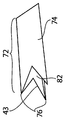
도 1c는 도 1a의 일체형 임플란트의 말단부의 확대 정면도이다.
도 2a는 다른 전형적인 일체형 플란트의 길이 방향 단면도이다.
도 2b는 도 2a의 일체형 임플란트의 말단부의 확대 정면도이다.
도 3은 일체형 전달 핀 조립체의 측면도이다.
도 4a 내지 도 4f는 전형적인 중공의 일체형 임플란트들의 등축도이다.
도 5는 다른 중공형의 일체형 임플란트의 정면도이다.
도 6a는 다른 일체형 임플란트의 정면도이다.
도 6b는 도 6a의 일체형 임플란트의 사시도이다.
도 7a 내지 도 7m은 예시적인 일체형 임플란트들의 횡단면의 기하학적 형상들의 예시도들이다.
도 8a 내지 도 8d는 도 1a의 일체형 임플란트를 이식하기 위한 전형적인 절차의 예시도들이다.
도 9 및 도 10은 각각 천골 및 골반 뼈(우측 장골 및 좌측 장골)들을 포함하는 사람의 골반대의 전방도 및 후방도이며, 천골은 천장 관절(간단히, SI-관절)에서 양 골반 뼈들과 연결된다.
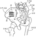
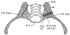
도 11 내지 도 13b는 각각 이식 전 상태 사시도, 이식된 상태 사시도, 이식된 상태의 전방도, 및 이식된 상태의 두개-미골부 단면도(cranio-caudal section)를 도시하는 해부도들이며, SI-관절의 고정을 위한 3개의 임플란트 구조들의 이식은 장골, SI-관절을 관통하여 천골 내로의 측면 접근을 사용한다.
도 14a 내지 도 14d는 이식된 상태의 전형적인 일체형 임플란트들의 해부도들이다.The novel features of the invention are set forth in detail in the appended claims. BRIEF DESCRIPTION OF THE DRAWINGS An improved understanding of the features and advantages of the present invention will be gained with reference to the following detailed description which sets forth illustrative embodiments, in which the principles of the invention are utilized in an exemplary embodiment, the accompanying drawings being as follows:
1A is a longitudinal cross-sectional view of a typical integral implant assembly.
1B is an enlarged front view of the distal end of the flexible lid of FIG. 1A.
1C is an enlarged front view of the distal portion of the integral implant of FIG. 1A.
Figure 2a is a longitudinal cross-sectional view of another exemplary integrated tool.
FIG. 2B is an enlarged front view of the distal end of the integral implant of FIG. 2A.
3 is a side view of the integral transmission pin assembly.
Figures 4A-4F are isometric views of typical hollow, integral implants.
5 is a front view of another hollow integral implant.
6A is a front view of another integral implant.
6B is a perspective view of the integral implant of FIG. 6A.
Figures 7A-7M are illustrations of geometric shapes of cross-sections of exemplary integrated implants.
Figures 8A-8D are illustrations of an exemplary procedure for implanting the integral implant of Figure 1A.
Figures 9 and 10 are anterior and posterior views of the human pelvic girdle, including sacral and pelvic bones (right iliac and left iliac), respectively, and the sacrum is connected to both pelvic bones in the cephalic joint (simply, SI-joint) .
Figs. 11 to 13B are dissection views showing a pre-implantation state perspective view, an implanted state perspective view, an anterior view of the implanted state, and a cranio-caudal section of the implanted state, Implantation of three implant structures for fixation uses a lateral approach into the sacrum through the iliac, SI-joints.
14A-14D are anatomical views of typical integrated implants in an implanted state.
지금부터 본 발명의 전형적인 실시예들을 상세히 참조할 것이며, 이들의 예들은 첨부 도면에 예시된다. 본 발명이 전형적인 실시예들과 관련하여 설명되지만, 본 발명이 전형적인 실시예들로 제한되는 것이 의도되지 않는다는 것이 이해될 것이다. 반대로, 본 발명은 본 명세서에서 설명된 본 발명의 사상 및 범즈 내에 포함될 수 있는, 대안예들, 수정예들 및 등가예들을 포함하는 것으로 의도된다.
Reference will now be made in detail to exemplary embodiments of the invention, examples of which are illustrated in the accompanying drawings. While the invention has been described in conjunction with exemplary embodiments, it is to be understood that the invention is not intended to be limited to the exemplary embodiments. On the contrary, the invention is intended to cover alternatives, modifications and equivalents, which may be included within the spirit and scope of the invention described herein.
본 발명의 다양한 양태들은 커팅 브로치 및/또는 커팅 버를 가지는 일체형 임플란트에 관한 것이다. 다양한 실시예들에서, 일체형 임플란트들은 천장 관절을 유합하기 위해 사용될 수 있다. 본 명세서에서 설명된 일체형 임플란트들은 또한 사람 환자 몸 안의 다른 뼈들을 유합하기 위해 사용될 수 있다. 예를 들면, 일체형 임플란트는 척추 및 다른 뼈들의 요추 구역을 유합하기 위해 사용될 수 있다. 이와 같이, 당업자는 천장 관절 유합과 관련된 전형적인 실시예가 이러한 유형의 유합에 제한되지 않으며 오히려 예로서 제시된다는 것을 구현할 것이다.
Various aspects of the present invention are directed to an integral implant having a cutting broach and / or a cutting bur. In various embodiments, integral implants can be used to union the ceiling joint. The integral implants described herein can also be used to fuse other bones in a human patient's body. For example, an integral implant can be used to fuse the lumbar region of the vertebrae and other bones. As such, those skilled in the art will realize that the exemplary embodiment associated with ceiling articulation is not limited to this type of union, but rather is presented as an example.
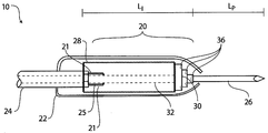
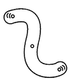
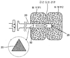
도 1a는 전형적인 일체형 임플란트 조립체의 길이 방향 단면도이다. 일체형 임플란트 조립체(10)는 일체형 임플란트(20), 가요성 덮개(22), 전달 봉(24), 및 전달 핀(26)을 포함한다. 전달 봉(24) 및 일체형 임플란트(20)는 삽관식일 수 있다. 캐뉼러(32)는 전달 핀(26)을 위한 접근을 제공할 수 있다. 전달 봉(24)은 전달 봉(24)의 반경보다 작은 반경을 가질 수 있는 나사형 말단부(threaded distal end; 25)를 포함할 수 있다. 나사형 말단부(25)는 일체형 임플란트 소켓(21)과 맞물릴 수 있다. 일체형 임플란트(20)는 소켓(21), 코어(28) 및 커팅 브로치(30)를 포함할 수 있다. 코어(28)는 선단부 및 말단부를 가질 수 있으며, 여기에서 용어 말단 및 선단은 전달 봉의 외측 단부(일체형 임플란트 소켓(21)과 맞물리지 않는 전달 봉의 부분)에 대해 사용된다. 코어(28)의 말단부는 커팅 브로치(30)에 커플링된다. 커팅 브로치(30)는 뼈를 드릴링하고 브로칭하는 부가 단계들 또는 별개의 단계에서 뼈를 브로칭하는 단계를 취하는 요구를 제거할 수 있다. 다양한 실시예들에서, 커팅 브로치(30)는 용접, 별개의 체결 장치들, 압입 끼워맞춤, 나사 결합들, 또는 다른 방법에 의해 코어(28)에 커플링될 수 있다. 다양한 실시예들에서, 커팅 브로치(30) 및 코어(28)는 기계가공, 몰딩, 압출 또는 다른 방법에 의해 단일 피스로서 생성될 수 있다.
1A is a longitudinal cross-sectional view of a typical integral implant assembly. The
일체형 임플란트(20)는 시간이 지남에 따라 뼈 또는 조직을 둘러쌈으로써 상당한 생체-흡수(bio-absorption) 또는 재흡수가 일어나지 않는 보철 분야에서 사용가능한 내구적인 재료로 형성될 수 있다. 일체형 임플란트(20)는 골절 또는 유합 위치를 안정화하기에 충분한 시간 동안 제 위치에 남아 있을 것이 의도된다. 일체형 임플란트(20)는 또한 환자 안 제 위치에 영구적으로 남아 있을 수 있다. 이 같은 재료들은 티타늄, 티타늄 합금들, 탄탈, 티바늄(tivanium)(알루미늄, 바나듐, 및 티타늄), 크롬 코발트, 수술용 강, 또는 임의의 다른 모든 관절 대체 금속 및/또는 세라믹, 소결 유리, 인공 뼈, 임의의 언시멘티드 금속(uncemented metal) 또는 세라믹 표면, 또는 이들의 조합물을 포함하지만 이에 제한되지 않는다. 대안적으로, 일체형 임플란트(20)는 적합한 내구적인 생물학적 재료 또는 생체 적합성 뼈-충전 재료와 같은 금속 및 생물학적 재료의 조합물로 형성될 수 있다. 일체형 임플란트(20)는 예를 들면 UV 광에 의해, 비-유동성 또는 고체 재료(예를 들면 PLA, PLGA, PGA, 또는 다른 유사 재료들과 같은 중합체들)로 경화되는 유동성 생물학적 재료, 예를 들면 아크릴 골형 시멘트로 성형될 수 있다.
The
일체형 임플란트(20)는 국부 해부학적 구조에 따른 크기를 가질 수 있다. 국부적 구조의 형태는 위치 및 이의 질병 또는 상처의 전문 의료진의 지식과 함께 사람의 골격 해부학의 교본들을 사용하여 전문 의료진에 의해 일반적으로 이해될 수 있다. 의사는 또한 예를 들면 단순 촬영 x-레이, 형광 투시경 x-레이, 또는 MRI 또는 CT 스캐닝뿐만 아니라 제공된 장비를 사용한 수술 중 크기 조절(sizing) 방법을 사용하여 목표 뼈 구역의 형태의 사전 분석을 기초로 하여 적절하게 크기 조절된 일체형 임플란트(20)의 치수들을 확인할 수 있다. 다양한 실시예들에서, 일체형 임플란트의 길이(LI)는 약 30mm 내지 70mm의 범위에 있다. 다양한 실시예들에서, 일체형 임플란트의 길이(LI)는 약 30mm, 35mm, 40mm, 45mm, 50mm, 55mm, 60mm, 65mm, 및 70mm이다.
The
일체형 임플란트(20)는 다양한 형상들을 가질 수 있고 다양한 횡단면의 기하학적 형상들을 가질 수 있다. 일체형 임플란트(20)는 일반적으로 곡선형(예를 들면, 라운드형(round) 또는 타원형) 횡단면 또는 일반적으로 직선형 횡단면(예를 들면, 정사각형 또는 직사각형 또는 삼각형) 또는 이들의 조합형 횡단면을 가질 수 있다. 일체형 임플란트(20)의 형상은 도 4 내지 도 7m에 대해 추가로 논의된다.
The
도 1a 및 도 2a에서, 일체형 임플란트(20, 50)들은 임플란트 안정성을 효과적으로 개선할 수 있는, 삼각형 형상으로 예시된다. 임플란트 안정성은 느슨해지지 않으면서 축방향, 측면 방향 및 회전 방향의 부하들을 저지하기 위한 임플란트의 기능으로서 규정될 수 있다. 안정성을 유지하면서 이러한 부하들을 견디는 임플란트의 기능은 중요하다. 주요 임플란트 안정성은 수술시에 달성되고 임플란트 설계에 의존할 수 있다. 주요 임플란트 안정성은 임플란트 기하학적 형상에 의해 영향을 받을 수 있다. 삼각형 기하학적 형상을 가지는 임플란트는 이식되면 회전, 이동 및 미동을 저지할 수 있으며 다른 기하학적 형상들에 비해 장점들을 제공할 수 있다. 초기 안정성이 기계적 특징물들에 관련될 수 있지만, 뼈 치료 과정이 궁극적으로 장기 안정성에 영향을 줄 수 있다.
In Figs. 1A and 2A, the
시간이 지남에 따라 달성되는 2차 임플란트 안정성은 주요 안정성의 수준 및 수술 및 임플란트에 대한 생물학적 반응에 종속될 수 있다. 새로이 형성된 뼈 조직은 임플란트/뼈 경계부에서의 공극을 채울 수 있어, 임플란트 표면과의 직접 접촉을 형성하여 표면 불균일부들과 맞물릴 수 있다. 새로이 형성된 뼈가 시간이 지남에 따라 발달할 때 이러한 상호 장금 효과가 증폭된다.
The secondary implant stability achieved over time can depend on the level of major stability and on the biological response to surgery and implants. The newly formed bone tissue can fill the voids at the implant / bone interface and form direct contact with the implant surface to engage the surface irregularities. This new mutation effect is amplified when newly formed bones develop over time.
일체형 임플란트(20)의 외측 표면은 말단부로부터 선단부로 연장하는 길이 방향 채널들을 가질 수 있다. 다양한 실시예들에서, 일체형 임플란트(20)의 외측 표면에는 주름이 형성되어 일련의 평행한 릿지들 및 말단부와 선단부 사이에서 길이 방향으로 연장하는 골(furrow)들을 갖는다. 채널들, 주름들 및 골들은 뼈들과 임플란트(20) 사이의 뼈 접촉 영역을 증가시킬 수 있다.
The outer surface of the
부가적으로, 일체형 임플란트(20)는 뼈의 인-그로스(in-growth), 온-그로스(on-growth), 또는 스루-그로스(through-growth)에 도움이 되는 외측 표면 상에 일 부분을 가질 수 있다. 다양한 실시예들에서, 상기 부분은 일체형 임플란트(20)의 전체 외측 표면을 포함할 수 있다. 뼈의 인-그로스, 온-그로스, 또는 스루-그로스는 관통공들, 다양한 표면 패턴들, 다양한 표면 질감들, 및/또는 구멍들, 또는 이들의 조합들을 포함할 수 있다. 다양한 실시예들에서, 외측 표면은 메시 구성(mesh configuration), 비드형(beaded) 구성, 기둥 구성, 구멍들 또는 천공부들 또는 뼈의 스루-그로스에 도움이 되는 임의의 표면을 가질 수 있다.
In addition, the
일체형 임플란트(20)의 외측 표면은 뼈 인-그로스 또는 스루-그로스를 증진하기 위해 코팅되고, 감싸지고, 또는 표면 처리될 수 있다. 다양한 실시예들에서, 코팅 재료는 뼈의 인-그로스, 조직 회복을 증진 및/또는 강화하고, 및/또는 염증, 감염 및 통증을 감소시킬 수 있는 생물학적 보조물을 포함할 수 있다. 샘물학적 보조물은 뼈 형성 단백질(BMP)들, 액체 또는 슬러리 캐리어 내의 수산화 인회석, 탈화골, 자가 이식편 또는 동종 이식편의 뼈, 진통제, 항생제, 및 스테로이드들과 같이 염증, 감염 및 통증을 감소시키기 위한 약제와 같은 성장 인자들을 포함할 수 있다. 다양한 실시예들에서, 성장 인자들은 rh-BMP-2 및/또는 rh-BMP-7, 또는 BMP의 임의의 다른 사람의 재조합제 형태와 같은 사람 재조합 성장 인자일 수 있다. 생물학적 보조물용 캐리어는 염수 또는 콜라겐 겔과 같은 액체 또는 겔일 수 있다. 생물학적 보조물은 또한 방출 제어형 제제(controlled released formulation)에서 캡슐화되거나 포함될 수 있어 생물학적 보조물은 더 긴 지속 기간에 걸쳐 임플란트 위치에서 환자에게 방출된다. 예를 들면, 방출 제어형 제제는 몇 일(days), 몇 주(days)(day), 몇 달(month) 동안 생물학적 보조물을 방출하도록 구성될 수 있고 치료하기 위해 임플란트 위치에 대해 취해질 추정 시간에 걸쳐 샐물학적 보조제를 방출하도록 구성될 수 있다. 일체형 임플란트(20)에 전달된 생물학적 보조물의 양은 일체형 임플란트(20)에 인가된 코팅 재료의 양을 제어하거나 변화시키고 및/또는 코팅 재료 내로 포함되는 생물학적 보조물의 양을 제어하거나 변화시키는 것과 같은, 다양한 기술들을 사용하여 제어될 수 있다. 특정 생물학적 보조물의 과도 사용이 국부 염증, 국부 통증, 또는 근통과 같은 부정적 영향을 초래할 수 있기 때문에, 전달된 생물학적 보조물의 양을 제어하는 것은 중요할 수 있다.
The outer surface of the
다양한 실시예들에서, 뼈의 인-그로스 부분, 온-그로스 부분, 또는 스루-그로스 부분은 일체형 임플란트(20) 상에 다공성 플라즈마 스프레이 코팅을 포함한다. 코팅은 확실한 고정/유합 및 예민한(acute) 웨이트 지지 성능을 지지하도록 설계된 생체 역학적 정밀 고정/유합 시스템을 생성할 수 있다.
In various embodiments, the in-grosse portion, on-grosse portion, or through-grosse portion of the bone comprises a porous plasma spray coating on the
대안적으로, 외측 표면은 자체적으로 본질적으로 다공성 메시, 하이드록시애피타이트(hydroxyapetite), 또는 다른 다공성 표면과 같은, 뼈의 인-그로스 또는 스루-그로스에 도움을 주는 구조를 보유하는 재료로 형성될 수 있다.
Alternatively, the outer surface may be formed of a material that itself has a structure that aids in phosphorus-gassing or through-grosing of the bone, such as a porous mesh, hydroxyapetite, or other porous surface .
뼈의 인-그로스 또는 스루-그로스 부분은 추가로 항균성, 항혈전성, 및 뼈 전도성 제제 또는 이들의 조합물과 같은 다양한 다른 코팅들로 덮일 수 있다. 다양한 실시예들에서, 완전한 일체형 임플란트(20)는 이 같은 제제들로 주입될 수 있다.
The in-grosse or through-grosse portion of the bone may additionally be covered with a variety of other coatings such as antimicrobial, antithrombogenic, and osteoconductive agents or combinations thereof. In various embodiments, a complete
도 1a에 도시된 일체형 임플란트 조립체(10)의 전달 핀(26)은 말단부에 날카롭거나 무딘 선단을 가질 수 있다. 전달 핀(26)은 일체형 임플란트(20)에 영구적으로 부착될 수 있다. 영구적으로 부착된 전달 핀(26)은 철회 가능할 수 있거나 맞물림 해제되어 일체형 임플란트(20) 내부로 슬립될 수 있다. 대안적으로, 전달 핀(26)은 제거 가능할 수 있다. 다양한 실시예들에서, 전달 핀(26)은 일체형 임플란트(20)의 부분이거나 전달 봉(24)의 부분일 수 있다. 다양한 실시예들에서, 전달 핀(26)의 길이(LP)는 약 0mm 내지 30mm의 범위 내에 있다. 다양한 실시예들에서, 전달 핀(26)의 길이(LP)는 약 0mm, 5mm, 10mm, 15mm, 20mm, 25mm 및 30mm이다. 다양한 실시예들에서, 전달 핀(26)의 길이(LP)는 약 0mm 내지 30mm의 거리만큼 일체형 임플란트(20)의 말단부를 넘어 연장한다. 다양한 실시예들에서, 전달 핀(26)의 길이(LP)는 약 0mm, 5mm, 10mm, 15mm, 20mm, 25mm, 및 30mm의 거리만큼 일체형 임플란트(20)의 말단부를 넘어 연장한다.
The
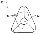
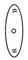
도 1b는 도 1a의 가요성 덮개의 말단부의 확대된 정면도이다. 가요성 덮개(22)는 일체형 임플란트(20)가 전진할 때 연 조직을 보호할 수 있는 전달 덮개로서 사용될 수 있다. 가요성 덮개가 뼈에 맞닿아 태핑될 때 가요성 덮개(22)는 펼쳐짐을 강제하는 말단부에 형성된 선단을 가질 수 있다. 가요성 덮개(22)의 선단의 설계는 연 조직을 통과하여 용이한 삽입을 제공할 수 있다. 가요성 덮개(22)는 외벽 부분(34)을 포함한다. 외벽 부분(34)은 예를 들면 대략 60도로 각도를 형성할 수 있어 삼각형의 정점들을 형성한다. 외벽 부분(34)은 실질적으로 평면이어서 말단부에 피라미드형 선단을 형성한다. 가요성 덮개는 열가소성 폴리에틸렌(예를 들면, 초고 분자량 폴리에틸렌, 고 분자 폴리에틸렌 또는 고 성능 폴리에틸렌), 유기 중합체 열가소성 수지(예를 들면 폴리에테르 에테르 켑톤), 열경화성 중합체, 탄성체 및 다른 재료 중 하나 또는 초과로 형성될 수 있다.
1B is an enlarged front view of the distal end of the flexible lid of FIG. 1A. The
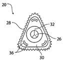
도 1c는 도 1a의 일체형 임플란트의 말단부의 확대 정면도이다. 일체형 임플란트(20)는 전달 핀(26), 코어(28), 커팅 브로치(30) 및 캐뉼러(32)를 포함한다. 커팅 브로치(30)는 브로칭 에지(36)들을 포함할 수 있다. 브로칭 에지(36)는 커팅 브로치(30)의 테이퍼진 말단부 상에 위치될 수 있다. 브로칭 에지(36)들은 일체형 임플란트(20)가 선형적으로 삽입될 때 뼈 재료를 제거하기 위해 사용된 치형부들을 포함할 수 있다.
1C is an enlarged front view of the distal portion of the integral implant of FIG. 1A. The
다양한 실시예들에서, 일체형 임플란트 조립체(10)는 삽관식 전달 봉(24) 및 표준 전달 핀(26), 예를 들면 스테인만 핀(Steinman pin)이 사용되는 삽관식 일체형 임플란트(20)를 포함한다. 다양한 실시예들에서, 일체형 임플란트 조립체(10)는 일체형 임플란트(20)에 커플링되는 전달 핀(26)을 포함한다. 일체형 임플란트(20) 또는 전달 봉(24) 내에 캐뉼러(32)가 없을 수 있다. 다양한 실시예들에서, 일체형 임플란트 조립체(10)는 전달 봉(24) 및 삽관식 일체형 임플란트(20)를 포함한다. 전달 봉(24)은 전달 핀(26)으로 커플링될 수 있다.
In various embodiments, the
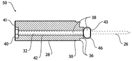
도 2a는 다른 전형적인 일체형 임플란트의 길이 방향 단면도이다. 도 2a의 일체형 임플란트(50)는 도 1a 및 도 1c의 코어(28) 및 커팅 브로치(30)를 포함한다. 일체형 임플란트(50)는 또한 커팅 버(38)에 커플링될 수 있다. 커팅 버(38)는 캐뉼러(32)를 가질 수 있으며 소켓(40), 샤프트(42), 및 커팅 조립체(46)를 포함할 수 있다. 커팅 버(38)는 도 1a의 일체형 임플란트와 동일한 재료로 형성될 수 있다. 커팅 버(38)는 일체형 임플란트(50)의 선단부(41)와 말단부(43) 사이로 연장할 수 있고 예를 들면 일체형 임플란트(50)의 중앙 축선을 따라 일체형 임플란트(50) 내에 위치 설정될 수 있다. 다양한 실시예들에서, 커팅 버(38)는 일체형 임플란트 구조의 일 부분일 수 있으며 일체형 임플란트(50)의 중앙 내에 있는 동안 회전되게 운동하도록 구성된다. 다양한 실시예들에서, 커팅 버(38)는 일체형 임플란트(50)의 중앙 내에서 병진 운동식으로 고정된다. 커팅 버(38)가 일체형 임플란트(50)의 일 부분일 때, 커팅 버(38)가 이식되어 유지될 수 있다.
Figure 2a is a longitudinal cross-sectional view of another exemplary integrated implant. The
다양한 실시예들에서, 커팅 버(38)는 접힐 수 있고 철회에 의해 제거가능하다. 커팅 버(38)는 일체형 임플란트(50)의 말단부를 넘어 연장할 수 있다. 다양한 실시예들에서, 커팅 버(38)는 약 0mm 내지 20mm의 범위 내의 거리만큼 일체형 임플란트(50)의 말단부를 넘어 연장할 수 있다. 다양한 실시예들에서, 커팅 버는 0mm, 5mm, 10mm, 15mm, 및 20mm의 거리만큼 일체형 임플란트(50)의 말단부를 넘어 연장할 수 있다.
In various embodiments, the cutting
소켓(40)은 커팅 버(38)의 선단부에 위치 설정되고 그 안으로 삽입 부분이 끼워져 맞춰지도록 설계되는 중공형 공동 또는 개구를 포함할 수 있다. 소켓(40)의 내측 표면은 정사각형, 육각형 또는 다른 기하학적 형상과 같은 기하학적 형상을 형성할 수 있다. 다양한 실시예들에서, 소켓(40)의 내측 표면은 구동기 또는 구동 장치에 끼워져 맞추어져 수용하도록 설계된다. 소켓(40)은 회전 구동력을 구동기로부터 샤프트(42)로 전달하기 위해 샤프트(42)에 커플링될 수 있다. 샤프트(42)는 소켓(40)의 말단부로부터 커팅 조립체(46)의 선단부로 길이 방향으로 연장할 수 있다.
The
커팅 조립체(46)는 반경 방향 외측으로 연장하고 중앙 축선을 중심으로 한 회전을 위해 장착될 수 있는 복수의 커팅 블레이드(48)들(도 2b에 도시됨)의 배열체를 포함할 수 있다. 작동 동안, 커팅 블레이드(48)들은 뼈를 관통하여 제거 및 커팅하기 위해 커팅 브로치(30)의 전방에서 외측으로 연장할 수 있다. 커팅 블레이드(48)들이 힌지 조립될 수 있어 커팅 블레이드들이 펼쳐질 수 있고 접혀질 수 있다. 커팅 블레이드(48)들은 플랜지에 부착될 수 있다. 커팅 블레이드(48)들은 뼈 제거가 완료된 후 일체형 임플란트(50)의 내부에서 철회될 수 있다. 하나 또는 그 초과의 채널들은 샤프트(42) 내 및/또는 코어(28) 내에 제공될 수 있어 커팅 블레이드(48)들에 의해 생성된 뼈 조각들이 커팅 영역으로부터 멀리 그리고 일체형 임플란트 내로 이동된다. 제거된 뼈 조각들은 나선홈들, 흡입, 가스 압력, 관류액의 도입 및/또는 다른 수단의 사용에 의해 임플란트로부터 배출될 수 있다. 일체형 임플란트(50)는 절단된 뼈 조각들 모두 또는 일부가 임플란트 내에 유지되고 및/또는 임플란트의 표면 부분으로 지향되도록 구성될 수 있어 치료 및 임플란트 내로의 뼈 인-그로스에 도움이 된다.
The cutting
일반적으로, 커팅 브로치(30)는 뼈의 날카롭거나 모가 난 모서리들을 커팅하기 위해 사용될 수 있고 커팅 버(38)는 뼈의 주 직경을 커팅하기 위해 사용될 수 있다. 일체형 임플란트(50)의 코어(28), 커팅 브로치(30) 및 커팅 버(38)는 도 1a 내지 도 1c의 일체형 임플란트(20)의 코어, 커팅 브로치 및 커팅 버와 유사한 방식으로 형성될 수 있다. 형성 과정은 도 1a 내지 도 1c에 대해 설명된 바와 같이, 유사한 재료로 그리고 유사한 몰딩 및 크기 조절 과정을 사용하여 일체형 임플란트를 구성하는 것을 포함할 수 있다.
Generally, the cutting
도 2b는 도 2a의 일체형 임플란트의 말단부의 확대된 정면도이다. 일체형 임플란트(50)는 코어(28), 커팅 브로치(30), 커팅 버(38) 및 캐뉼러(32)를 포함한다. 커팅 브로치(30)는 브로칭 에지(36)를 포함할 수 있다. 브로칭 에지(36)들은 커팅 브로치(30)의 테이퍼진 말단부 상에 위치될 수 있다. 일체형 임플란트(50)가 선형적으로 삽입될 때 브로칭 에지(36)들은 뼈 재료를 제거하기 위해 사용된 치형부들을 포함할 수 있다. 커팅 버(38)는 뼈를 관통하여 구멍을 형성하기 위한 커팅 블레이드(48)를 구비한 커팅 조립체(46)를 포함할 수 있다.
Figure 2B is an enlarged front view of the distal portion of the integral implant of Figure 2A. The
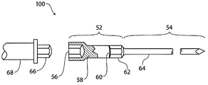
도 3은 일체형 전달 핀 조립체의 측면도이다. 일체형 전달 핀 조립체(100)는 구동 장치(52) 및 전달 핀(54)을 포함할 수 있다. 구동 장치(52)는 구동 소켓(56), 구동 샤프트(58), 및 구동 부재(60)를 포함할 수 있다. 전달 핀(54)은 핀 소켓(62) 및 핀 샤프트(64)를 포함할 수 있다. 이러한 실시예의 일체형 전달 핀 조립체(100)는 커팅 버를 회전되게 구동하도록 커팅 버(38) 내에 부분적으로 수용되도록 구성된다. 특히, 전달 핀(54)은 커팅 버(38)의 캐뉼러(32) 내에 슬라이드 가능하게 수용되도록 그리고 도 2a에 점선으로 표시된, 커팅 버(38)의 말단부로부터 연장하도록 구성된다. 구동 부재(60)는 도 2a에 도시된, 임플란트 소켓(40) 내에 슬라이드 가능하게 수용되고 임플란트 소켓과 함께 회전이 잠금되도록 구성된다. 구동 소켓(56)은 드릴 부재(66)를 수용하거나 끼워져 맞춰질 수 있다. 드릴 부재(66)는 드릴 샤프트(68) 및 드릴(도시 안됨)에 커플링된다. 다양한 실시예들에서, 드릴은 임팩트 드릴(impact drill)이다.
3 is a side view of the integral transmission pin assembly. The integral
다양한 실시예들에서, 구동 장치(52) 및 전달 핀(54)은 조립될 수 있는 별개의 피스들일 수 있다. 작동 중, 드릴 샤프트(68)는 드릴 부재(66)를 회전 방향을 구동하는 회전 방향으로 터닝한다. 드릴 부재(66)는 구동 소켓(56)과 맞물려서 구동 장치(52)를 회전 방향으로 구동한다. 구동 소켓(56)의 내측 표면은 육각형 또는 다른 기하학적 형상과 같은 기하학적 형상을 형성할 수 있다. 구동 샤프트(58)는 구동 소켓(56)의 말단부와 구동 부재(60)의 선단부 사이에서 길이 방향으로 연장한다. 구동 부재(60)는 핀 소켓(62)과 맞물릴 수 있다.
In various embodiments, the
핀 소켓(62)은 구동 부재(60)에 의해 회전 방향으로 구동된다. 핀 소켓(62)의 내측 표면은 육각형 또는 다른 기하학적 형상과 같은 기하학적 형상을 형성할 수 있다. 핀 소켓(62)의 말단부는 LS의 길이를 가지는 핀 샤프트(64)에 커플링될 수 있다. 핀 샤프트(64)의 말단부는 포인트를 형성할 수 있다. 다양한 실시예들에서, 핀 샤프트의 길이(LS)가 약 30mm 내지 90mm의 범위 내에 있다. 다양한 실시예들에서, 핀 샤프트(64)의 길이(LS)는 약 30mm, 35mm, 40mm, 45mm, 50mm, 55mm, 60mm, 65mm, 70mm, 75mm, 80mm, 85mm, 및 90mm이다.
The
전달 핀 조립체(100)는 일체형 임플란트(50)를 이식하기 위해 사용될 수 있다. 전달 핀 조립체(100)는 다양한 금속들, 금속 합금들(예를 들면, 스테인리스 강, 티타늄 합금), 중합체들, 탄소 섬유들, 및 다른 재료들로 형성될 수 있다.
The
대안적으로, 구동 장치(52) 및 전달 핀(54)은 단일 피스로서 형성되거나 단일 피스를 형성하도록 함께 유합될 수 있다. 작동 중, 일체형 임플란트(50)와 같이, 단일 구동 부재/구동 핀 피스, 드릴 부재(66)를 포함하는 일 실시예는 구동 소켓(56)과 맞물려서 단일 피스를 회전 방향으로 이동할 수 있다. 구동 소켓(56)은 구동 부재(60)에 커플링될 수 있다. 구동 부재(60)는 커팅 버(도 2a에 도시됨)의 선단부 상에서 소켓(40)과 맞물릴 수 있고 커팅 버(38)를 회전 방향으로 구동할 수 있다.
Alternatively, the
다양한 실시예들에서, 핀 샤프트(64)의 길이(LS)는 약 0mm 내지 30mm의 거리만큼 커팅 버(38)의 말단부를 넘어 연장한다. 다양한 실시예들에서, 핀 샤프트(64)의 길이(LS)는 약 0mm, 5mm, 10mm, 15mm, 20mm, 25mm, 및 30mm의 거리만큼 커팅 버(38)의 말단부를 넘어 연장한다. 핀 샤프트(64)의 길이(LS)는 일체형 임플란트(50)의 길이로 특정될 수 있다. 구동 장치(52)의 길이(LD)는 일체형 임플란트(50)가 뼈 내로 구동될 거리일 수 있다. 다양한 실시예들에서, 구동 장치(52)의 길이(LD)는 약 30mm 내지 150mm의 범위이다. 다양한 실시예들에서, 구동 장치(52)의 길이(LD)는 30mm, 60mm, 90mm, 120mm, and 150mm이다.
In various embodiments, the length L S of the
일체형 임플란트(20 및 50)들은 임플란트가 환자 안으로 너무 멀리 구동되는 것을 방지하기 위한 안전 특징물을 포함할 수 있다. 다양한 실시예들에서, 안전 특징물은 임플란트(20 및 50) 상에 마킹, 돌기 또는 소정의 다른 특징물을 포함할 수 있다. 돌기는 전달 봉(24) 또는 드릴 샤프트(68) 상에 위치될 수 있으며 뼈 내로의 추가 전진을 방지하기 위하여 환자의 피부 또는 외측 장골 표면과 접촉하게 될 수 있다. 마킹은 전달 봉(24) 또는 드릴 샤프트(68) 상에 위치될 수 있고 삽입 깊이의 측정, 예를 들면 깊이 게이지를 표시할 수 있다.
The
도 4a 내지 도 7m에 대해 논의된 일체형 임플란트 구조들은 도 1a 내지 도 1c의 일체형 임플란트(20)와 동일한 방식으로 형성될 수 있다. 형성은 도 1a 내지 도 1c에 대해 설명된 것과 유사한 몰딩 및 크기 조절 과정을 사용하여 그리고 유사 재료로 일체형 임플란트를 구성하는 것을 포함할 수 있다.
The integral implant structures discussed with respect to Figs. 4A-7M may be formed in the same manner as the
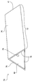
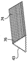
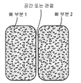
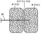
도 4a 내지 도 4e는 전형적인 중공의 일체형 임플란트들의 측면도들이다. 도 4e의 중공의 일체형 임플란트(70)는 3개의 벽 부분(74)들로 이루어지는 코어(72)를 포함한다. 코어(72)는 하나의 다면 벽 부분(74) 또는 별개의 다수의 상호 잠금 가능한 벽 부분(74)들로서 형성될 수 있다. 다양한 실시예들에서, 다수의 벽 부분(74)들은 독립적으로 이식되고 벽 부분 에지들을 상호 잠금함으로써 조립된다. 벽 부분(74)의 말단부(43)는 커팅 에지(76)를 가질 수 있다. 전달 핀 구멍(78)은 코어(72) 내에 있을 수 있으며 말단부(43)와 선단부(41) 사이로 연장할 수 있다. 다양한 실시예들에서, 각각의 전달 핀 구멍(78)은 납땜될 수 있거나 그렇지 않으면 벽 부분의 내측 표면에 부착될 수 있는 구조로 형성될 수 있다. 다른 실시예들에서, 전달 핀 구멍(들)은 벽 부분(들)과 일체로 형성될 수 있다. 전달 핀 구멍(들)은 벽 부분(들)의 에지(들)에 및/또는 임플란트의 외측을 따라 위치될 수 있다.
Figures 4A-4E are side views of typical hollow, integral implants. The hollow
커팅 에지(76)들은 주름형 에지, 레이저 에지, 톱니형 에지 또는 소정의 다른 커팅 에지로서 실시될 수 있다. 다양한 실시예들에서, 커팅 에지(76)들은 테이퍼진다(도 4b 참조). 커팅 에지(76)들은 말단부(43)의 일 부분을 따라 연장할 수 있다. 예를 들면, 커팅 에지(76)들은 말단부(43)(도시안됨)에서 벽 부분(74)들의 내측 표면상에 위치 설정될 수 있다. 커팅 에지(76)들을 가지는 벽 부분(74)들은 뼈를 관통하여 커팅하도록 구성될 수 있고 뼈가 벽 부분(74)들에 의해 형성된 중공형 구조를 통과하여 지나가는 것을 허용할 수 있다.
The cutting edges 76 may be embodied as corrugated edges, laser edges, sawtooth edges or any other cutting edge. In various embodiments, the cutting edges 76 are tapered (see FIG. 4B). The cutting edges 76 may extend along a portion of the
벽 부분(74)들은 뼈의 인-그로스(도 4c 참조)에 도움이 되는 천공부(80)를 가질 수 있다. 다양한 실시예들에서, 벽 부분(74)들은 선단부(41)와 말단부(43) 사이의 전체 표면을 따라 주름질 수 있다(도 4d 참조). 벽 부분(74)들의 외측 표면은 뼈의 인-그로스 또는 온-그로스를 증진하기 위해 다공성일 수 있다. 다양한 실시예들에서, 벽 부분(74)들의 벽의 두께는 약 1mm이다. 다양한 실시예들에서, 벽 부분(74)들의 두께는 약 0.5mm 내지 5mm의 범위 내에 있다. 다양한 실시예들에서, 일체형 임플란트(70)의 길이는 약 30mm 내지 70mm의 범위 내에 있다. 다양한 실시예들에서, 일체형 임플란트(70)의 길이는 약 30mm, 35mm, 40mm, 45mm, 50mm, 55mm, 60mm, 65mm, 및 70mm이다.
The
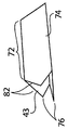
다양한 실시예들에서, 각각의 벽 부분(74)의 말단부(43)는 하나 내지 그 초과의 포인트들로 테이퍼질 수 있다. 도 4e 및 도 4f의 일체형 임플란트들은 커팅 에지(76)들, 코어(72) 및 테이퍼진 말단부(82)들을 구비한 3개의 벽 부분(74)들을 포함하는 전형적인 실시예들을 예시한다. 다양한 실시예들에서, 테이퍼진 말단부(82)들 각각은 각각의 벽 부분(74)의 말단부의 중앙에(도 4e) 또는 삼각형 횡단면의 정점들에(도 4f) 포인트를 형성한다. 테이퍼진 말단부(82)들은 뼈 내로의 코어(72)의 구동을 용이하게 하도록 점차적으로 증가하는 표면적을 제공한다.
In various embodiments, the
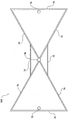
도 5는 다른 중공의 일체형 임플란트의 정면도이다. 중공의 일체형 임플란트(100)는 벽 부분(74)들, 커팅 에지(76)들 및 전달 핀 구멍(78)들을 포함한다. 벽 부분(74)들은 I자 빔과 유사한 중공 형상을 형성할 수 있다. I자 빔의 각각의 반부는 삼각형을 형성하는 3개의 벽 부분(74)들로 형성될 수 있다. 두 개의 삼각형들은 각각의 삼각형에 대한 정점에서 함께 커플링될 수 있다. 부가 벽 부분(75)은 연결된 정점들의 각각의 측부 상에서 두 개의 삼각형들을 연결할 수 있다. 두 개의 삼각형들은 보우-타이 형상의 구성을 형성하도록 정점에서 함께 커플링할 수 있다. 벽 부분(74 및 75)들의 벽의 두께는 약 1mm일 수 있다. 다양한 실시예들에서, 벽 부분(74 및 75)들의 두께는 약 0.5mm 내지 5mm의 범위 내에 있다. 다양한 실시예들에서, 일체형 임플란트(100)의 길이은 약 30mm 내지 70mm의 범위 내에 있다. 다양한 실시예들에서, 일체형 임플란트(100)의 길이는 약 30mm, 35mm, 40mm, 45mm, 50mm, 55mm, 60mm, 65mm, 및 70mm이다.
5 is a front view of another hollow integral implant. The hollow,
커팅 에지(76)들은 벽 부분(74)들 중 하나 또는 그 초과의 벽 부분들 상에 구현될 수 있다. 다양한 실시예들에서, 각각의 벽 부분(74)은 커팅 에지(76)를 포함할 수 있다. 각각의 커팅 에지(76)는 도 4a 내지 도 4e에 대해 논의된 커팅 에지들 중 어느 하나로서 구현될 수 있다.
The cutting edges 76 may be implemented on one or more of the
중공의 일체형 임플란트(100)는 하나 또는 그 초과의 전달 핀(78)들일 수 있다. 각각의 전달 핀 구멍은 전달 핀을 수용하도록 구성될 수 있다. 다양한 실시예들에서, 각각의 전달 핀 구멍(78)은 벽 부분의 내부, 중간 또는 외부 구역에 납땜되거나 그렇지 않으면 부착되거나 형성될 수 있는 구조로 형성될 수 있다. 커팅 에지(76)들을 가지는 벽 부분(74)들은 뼈를 관통하여 커팅하도록 구성될 수 있고 뼈가 벽 부분(74)들에 의해 형성된 중공형 구조를 통과하여 지나가는 것을 허용할 수 있다.
The hollow
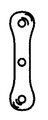
도 6a 및 도 6b는 각각 다른 일체형 임플란트의 정면도 및 사시도이다. 중공의 또는 개방된 일체형 임플란트(100)는 벽 부분(74)들 및 커팅 에지(76)들을 포함한다. 비록 전달 핀 구멍(78)이 예시되지 않았지만, 일체형 임플란트(110)는 하나 또는 그 초과의 전달 핀 구멍(78)들을 포함할 수 있다. 벽 부분(74)들은 I자 빔 형상을 형성할 수 있다. I자 빔 형상은 문자 "I"를 형성하는 3개의 벽 부분(74)들에 의해 형성될 수 있다. 다양한 실시예들에서, 빌딩 구성에서 사용된 I자 빔 구성에 비해, 일체형 임플란트(110)는 I자 벽 부분(74) 및 상부 및 바닥 벽 부분(74)들 사이의 접합부에서 직각을 요구하지 않을 수 있다(도 14b 참조).
6A and 6B are a front view and a perspective view of different integrated implants, respectively. The hollow or open
커팅 에지(76)들은 벽 부분(74)들 중 하나 또는 그 초과의 벽 부분들 상에 구현될 수 있다. 다양한 실시예들에서, 각각의 벽 부분(74)은 커팅 에지(76)를 포함할 수 있다. 각각의 커팅 에지(76)는 도 4a 내지 도 4e에 대해 논의된 커팅 에지들 중 어느 하나로서 구현될 수 있다. 벽 부분(74 및 75)들의 벽의 두께는 약 1mm일 수 있다. 다양한 실시예들에서, 벽 부분(74, 75)들의 두께는 약 0.5mm 내지 5mm의 범위 내에 있다. 다양한 실시예들에서, 일체형 임플란트(110)의 길이는 약 10mm 내지 70mm의 범위 내에 있다. 다양한 실시예들에서, 일체형 임플란트(110)의 길이는 약 30mm, 35mm, 40mm, 45mm, 50mm, 55mm, 60mm, 65mm, 및 70mm이다.
The cutting edges 76 may be implemented on one or more of the
도 7a 내지 도 7m은 전형적인 일체형 임플란트들의 횡단면의 기하학적 형상의 예시들이다. 도 7a 내지 도 7m 각각은 기하학적 형상, 전달 핀 구멍 및 브로칭 에지들을 예시한다.
Figures 7A-7M are examples of geometric shapes of cross-sections of typical integrated implants. Figures 7A-7M each illustrate geometric shapes, transmission pin holes, and broaching edges.
도 7a는 3개 다리를 구비한(tri-legged) 일체형 임플란트를 예시한다. 도 7a의 일체형 임플란트는 3개의 다리들을 포함하며 각각의 다리는 리그의 단부를 향하여 브로칭 에지들을 갖는다. 도 7a의 일체형 임플란트는 임플란트의 중앙에 전달 핀 구멍을 더 포함한다. 도 7b는 5개의 포인트들과 같은 복수의 포인트들을 가지는 별 형상의 일체형 임플란트를 예시한다. 각각의 포인트는 브로칭 에지들을 포함할 수 있고, 전달 핀 구멍은 별 형상의 일체형 임플란트의 중앙에 위치될 수 있다.
Figure 7A illustrates a tri-legged integral implant. The monolithic implant of Figure 7a comprises three legs, each leg having brooding edges towards the end of the ligature. The monolithic implant of Fig. 7A further includes a transfer pin hole in the center of the implant. Figure 7b illustrates a star-shaped monolithic implant having a plurality of points, such as five points. Each point may include the broaching edges, and the transfer pin hole may be located in the center of the star-shaped integral implant.
도 7c는 T-형상의 일체형 임플란트를 예시한다. T-형상의 일체형 임플란트의 각각의 모서리는 브로칭 에지들을 포함할 수 있다. 전달 핀 구멍은 예를 들면 T-형상의 수평 부분을 따라 중앙에 위치되는 것과 같이, 다양한 위치들에서 T-형상의 일체형 임플란트 내에 위치 설정될 수 있다. 도 7d는 4개의 포인트들을 가지는 연(kite) 형상 또는 다이아몬드 형상의 일체형 임플란트를 예시한다. 각각의 포인트는 브로칭 에지들을 포함할 수 있고, 전달 핀 구멍은 연 또는 다이아몬드 형상의 일체형 임플란트의 중앙에 위치 설정될 수 있다.
Fig. 7C illustrates a T-shaped integral implant. Each edge of the T-shaped integral implant may include the broaching edges. The transfer pin hole can be positioned in a T-shaped integral implant at various locations, for example centered along the horizontal portion of the T-shape. FIG. 7D illustrates a kite-shaped or diamond-shaped integral implant having four points. Each point may include broaching edges and the transfer pin orifice may be positioned in the center of a soft or diamond-shaped integral implant.
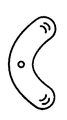
도 7e는 곡선형 단부의 4개의 포인트를 구비한 별 형상의 일체형 임플란트를 에시한다. 곡선형의 별 형상의 일체형 임플란트는 4개의 만곡형 연장부들을 가지며 이 연장부 각각은 브로칭 에지를 포함한다. 전달 핀 구멍은 별의 중앙에 위치될 수 있다. 에지들은 도 7e에 예시된 별 형상의 임플란트보다 적게 라운드 처리(round)될 수 있거나 크게 라운드 처리될 수 있다. 도 7f는 직선형 단부의 4개의 포인트를 구비한 별 형상 또는 X-형상의 일체형 임플란트를 예시한다. 직선의 별-형상의 일체형 임플란트는 4개의 직선 연장부들을 가지며 이 연장부들 각각은 브로칭 에지 및 별의 중앙에 전달 핀 구멍을 포함한다.
FIG. 7E illustrates a star-shaped integral implant having four points of a curved end. The curved, star-shaped, integral implant has four curved extensions, each of which includes a broaching edge. The transmission pin hole can be located in the center of the star. The edges may be rounded less than the star shaped implant illustrated in Figure 7e or may be largely rounded. Figure 7f illustrates a monolithic implant of a star or X-shape with four points of a straight end. Straight star-shaped integral implants have four straight extensions, each of which includes a breaching edge and a transfer pin hole in the center of the star.
도 7g는 아령 형상의 일체형 임플란트를 예시한다. 도 7g의 일체형 임플란트는 임플란트의 두 개의 단부들 각각 및 중앙에 전달 핀 구멍을 포함한다. 각각의 단부는 또한 브로칭 에지들을 가질 수 있다. 도 7h는 콩(bean) 형상의 일체형 임플란트를 예시한다. 콩 형상의 일체형 임플란트는 일체형 임플란트의 두 개의 단부들 각각에서 임플란란트 중앙 및 브로칭 에지들에서 전달 핀 구멍을 포함한다. 도 7i는 중앙 및 각각의 단부에서 전달 핀 구멍을 가지는 S자 형상의 일체형 임플란트를 예시한다. 브로칭 에지들은 일체형 임플란트 단부들에 위치될 수 있다.
Fig. 7G illustrates a dumbbell-shaped integral implant. The monolithic implant of Figure 7g comprises a transfer pin hole in each of the two ends of the implant and in the center. Each end may also have broaching edges. Figure 7h illustrates an integrated implant in the form of a bean. The bean-shaped monolithic implant includes a transfer pin hole at the implant center and at the broaching edges at each of the two ends of the monolithic implant. Fig. 7i illustrates an S-shaped integral implant having a central and a transfer pin hole at each end. The broaching edges may be located at the integral implant ends.
도 7j는 정사각형 형상의 일체형 임플란트를 예시한다. 정사각형 형상의 임플란트는 임플란트의 각각의 모서리에 브로칭 에지들 및 정사각형 형상의 중앙에 전달 핀 구멍을 포함한다. 도 7k는 타원형의 좁은 단부들에 브로칭 에지들 및 타원형의 중앙에 전달 핀 구멍을 가지는 타원형 형상의 일체형 임플란트를 예시한다. 도 7l은 Z자 형상의 일체형 임플란트를 예시한다. 도 7l의 일체형 임플란트는 Z자 형상의 중앙 수직 부분을 따라 전달 핀 구멍뿐만 아니라 하나 또는 그 초과의 단부들에서 전달 핀 구멍을 포함할 수 있다. 브로칭 에지들은 또한 각각의 단부에 위치될 수 있다. 도 7m은 V자 형상의 일체형 임플란트를 예시한다. 도 7m의 일체형 임플란트는 도시된 도립형 V자 형상의 상부에서 전달 핀 구멍뿐만 아니라 하나 또는 그 초과의 단부들에서 전달 핀 구멍을 포함할 수 있다. 브로칭 에지들은 또한 두 개의 V자 형상의 단부들 중 하나 또는 그 초과의 단부들에 위치 설정될 수 있다.
7J illustrates an integral implant of a square shape. Square shaped implants include broaching edges at each edge of the implant and a transfer pin hole at the center of the square shape. 7k illustrates an elliptical integral implant having broaching edges at narrow ends of the ellipse and a transfer pin hole at the center of the ellipse. FIG. 71 illustrates an integral implant of a Z-shape. The monolithic implant of FIG. 71 may include a transfer pin hole along the central vertical portion of the Z-shape as well as a transfer pin hole at one or more ends. The broaching edges may also be located at each end. FIG. 7M illustrates a V-shaped integral implant. The monolithic implant of Figure 7m may include a transfer pin hole at the top of the illustrated inverted V shape as well as at one or more ends. The broaching edges may also be positioned at one or more of the two V-shaped ends.
도 8a 내지 도 8d는 도 1a의 일체형 임플란트를 이식하기 위한 전형적인 절차를 예시한다. SI-관절 내의 일체형 임플란트(20)의 특별한 이식 기술들의 더욱 상세하고 해부학적으로 초점이 맞추어진 설명들이 도 9 내지 도 13b에 대해 설명된다.
8A-8D illustrate a typical procedure for implanting the integral implant of FIG. 1A. More detailed and anatomically focused explanations of the special implantation techniques of the
의사는 고정되거나 유합되는(관절 고정되는(arthrodesed)) 뼈 부분들 또는 인접 벽 구역들(도 8a 참조)을 확인한다. TV 스트린 상에 디스플레이되는 라이브 이미지 피드(live image feed)를 생성하기 위하여 종래의 시각화 기법들에 의해 지원된, 예를 들면, C-암(C-arm)들 또는 형광 투시경들과 같은 X-레이 이미지 증폭기들을 사용하여, 전달 핀(26)은 종래의 수단(도 8b 참조)에 의해 하나의 인접한 뼈 부분 또는 구역(뼈 부분 1)을 관통하여 또는 개재되는 공간 또는 관절을 관통하여 부분적으로 다른 인접한 뼈 부분 또는 구역(뼈 부분 2) 내로 도입될 수 있다.
The physician identifies fixed or unioned (arthrodesed) bone sections or adjacent wall sections (see FIG. 8A). Such as, for example, C-arms or fluoroscopes, supported by conventional visualization techniques to create a live image feed displayed on a TV screen, Using the ray image amplifiers, the
삽관식 드릴 비트(90)는 전달 핀(26)(도 8c 참조)를 지나 통과할 수 있어 하나의 인접한 뼈 부분 또는 구역을 관통하여 개재되는 공간 또는 관절을 관통하여 그리고 부분적으로 다른 인접한 뼈 부분 또는 구역 내로 파일럿 삽입 경로 또는 보어(92)를 형성한다. 단일 드릴 비트 또는 다수의 드릴 비트(90)들은 원하는 크기 및 구성의 파일럿 보어(902)를 생성하기 위하여 뼈 세편(bone fragment)들 또는 뼈 표면들을 관통하여 천공하도록 적용될 수 있다. 파일럿 보어(92)가 완성될 때, 삽관식 드릴 비트(90)가 제거된다.
The
예시된 실시예(도 8d 참조)에서 삼각형인 일체형 임플란트(20)는 파일럿 보어(92)를 관통하여 전달 핀(26) 위로 태핑된다. 일체형 임플란트(20)는 파일럿 보어(92)의 에지들을 따라 커팅되어 하나의 인접한 뼈 부분 또는 구역을 관통하여 개재하는 공간 또는 관절을 관통하여, 부분적으로 다른 인접한 뼈 부분 또는 구역 내로 일체형 임플란트(20)의 기하학적 형상을 수용하도록 원하는 프로파일을 형성한다.
In the illustrated embodiment (see FIG. 8D), the triangular
다양한 실시예들에서, 일체형 임플란트(20)는 파일럿 삽입 경로 또는 보어(92)를 형성하지 않으면서 위치 설정될 수 있다. 일체형 임플란트(20)는 도 1a 내지 도 2b에 대해 설명된 안전 멈춤 특징물에 의해 전진이 방지될 때까지 전달 봉을 직접 태핑함으로써 위치 설정될 수 있다.
In various embodiments, the
도 2a 및 도 2b에 도시된 일체형 임플란트(50)의 경우, 임플란트 구조는 커팅 브로치(30) 및 커팅 버(38)를 포함한다. 커팅 버(38)의 부가는 별개의 삽관식 드릴 비트(90)에 의해 뼈 내에 파일럿 보어(92)의 생성의 제거를 허용한다. 오히려, 파일럿 보어(92)는 일체형 임플란트(50)의 부분으로서 커팅 버(38)에 의해 생성된다. 따라서, 일체형 임플란트(50)는 파일럿 보어(92)를 발생시키기 위해 사용될 수 있으며 동시에 일체형 임플란트는 하나의 인접한 뼈 부분 또는 구역을 관통하여, 개재하는 공간 또는 관절을 관통하여, 부분적으로 다른 인접한 뼈 부분 또는 구역 내로 위치 설정된다. 일체형 임플란트(50)는 파일럿 보어가 형성되는 동안 동시에 위치 내로 태핑될 수 있다.
In the case of the
도 9 및 도 10은 각각 천골 및 골반뼈들(우측 장골, 및 좌측 장골)을 포함하는 사람의 골반대의 전방 및 전후방 도면들이며, 천골은 천장 관절(간단히, SI-관절)에서 양 골반 뼈들과 연결된다. 도 1a 및 도 2a(및 대안적 실시예에서)에 도시된 것과 같은 세장의 스템(stem)-형 일체형 임플란트 구조(20, 50)들은 몸에 최소로 칼을 대는 방식(minimally invasive manner)으로 SI-관절(도 9 및 도 10에서 각각 전방도 및 후방도로 도시된)의 고정을 가능하게 한다. 일체형 임플란트 구조(20, 50)들은 두 개의 대안적인 수술적 접근, 즉 측면 접근 또는 후방-측면 접근의 사용을 통하여 효과적으로 이식될 수 있다. 어느 한 절차가 바람직하게는 TV 스크린상에 디스플레이되는 라이브 이미지 피드를 생성하기 위하여 종래의 측면 및/또는 전-후방(A-P) 시각화 기법들에 의해, 예를 들면,C-암들 또는 형광 투시경들과 같은 X-레이 이미지 증폭기들을 사용하여 도움을 받는다.
9 and 10 are front and front and rear views of a human pelvic girdle including sacral and pelvic bones (right iliac and left iliac), respectively, and the sacrum is connected to both pelvic bones at the cephalic joint (simply, SI-joint) do. The stem-type
도 11 내지 도 13b는 각각 이식 전 사시도, 이식 사시도, 이식 후 도면 및 이식된 두개-미골부 단면도로 도시된 해부도이며, SI-관절의 고정을 위한 3개의 임플란트 구조들의 이식은 측면 접근을 사용한다. 측면 접근의 일 실시예에서(도 11 내지 도 13b 참조), 하나 또는 그 초과의 일체형 임플란트 구조(20, 50)들은 측면에서 장골, SI-관절을 관통하여 천골 내로 도입된다. 일체형 임플란트 구조(20, 50)들의 이러한 경로 및 결과적인 배치가 도 12 내지 도 13b에 최상으로 도시된다. 예시된 실시예에서, 3개의 일체형 임플란트 구조(20, 50)들이 이러한 방식으로 배치된다. 또한, 예시된 실시예들에서, 일체형 임플란트 구조(20, 50)들은 단면이 삼각형이지만, 앞에서 설명된 바와 같이 다른 횡단면들의 일체형 임플란트 구조들이 사용될 수 있다는 것이 인정되어야 한다.
Figs. 11 to 13B are exploded perspective views, a transplant perspective view, a post implantation view, and a transplanted craniofacial cross-sectional view, respectively, and the implantation of three implant structures for fixation of the SI joint uses a lateral approach . In one embodiment of the lateral approach (see Figs. 11 to 13B), one or more
측면 이식 절차를 수행하기 전에, 의사는 예를 들면 포틴 핑거 테스트(Fortin finger test), 싸이 스러스트(thigh thrust), FABER, 겐슬런의 압착(Gaenslen's compression), 디스트랙션(distraction), 및 진단 SI 관절 주사(diagnostic SI joint injection)를 사용하여 고정 또는 유합(관절 고정)될 SI-관절 부분들을 확인한다.
Prior to performing the lateral implantation procedure, the physician may perform, for example, a Fortin finger test, thigh thrust, FABER, Gaenslen ' s compression, distraction, Use the scan (diagnostic SI joint injection) to identify the SI-joint parts to be fixed or union (joint fixation).
측면, 인렛(inlet) 및 아웃렛(outlet) C-암 도면들에 의해 지원되고, 환자가 엎드린 위치(복부를 대고)로 누워있으면서, 의사는 진정한 측면 위치를 제공하기 위하여 측면 가시화를 사용하는 대좌골절흔(greater sciatic notch)들을 정렬한다. 3cm 절개는 장골에 대한 무딘-조직 분리에 의해 후속된, 천골관의 후부 피질과 정렬되어 시작된다. 측면도로부터, 핀 슬리이브(도시안됨)를 구비한 전달 핀(26), 예를 들면 스타인만 핀은 천골 단부판 보다 아래 위치에서 그리고 완만한 각도(예를 들면 도 13b에 도시된, 플로어(floor)로부터 15˚내지 20˚)로 장골에 놓여져 시작한다. 아웃렛 도면에서, 전달 핀(26)은 천골 단부판에 대해 평행하게 되어야 하고 천골 단부판으로부터 약간 떨어져 각도를 형성하여야 한다. 측면도에서, 전달 핀(26)은 천골 전방 벽보다 후방에 있어야 한다. 아웃렛에서, 전달 핀(26)은 천골 내부 구멍 및 정중선의 측면보다 위에 있어야 한다. 이는 일반적으로 도 8a 및 도 8b에 도식적으로 도시된 순서에 대응한다. 연 조직 프로텍터(도시 안됨) 또는 가요성 덮개(22)는 바람직하게는 전달 핀(26) 위로 그리고 핀 슬리이브를 제거하기 전에 장골에 대해 확실히 슬립된다. 인렛 도면에서, 전달 핀(26)의 궤적은 환자의 시상 봉합 정중선(sagittal midline) 앞의 전방 천골 피질을 관통하지 않아야 한다.
While the patient is supported by the side, inlet and outlet C-arm drawings, and the patient is lying at the prone position (abdomen), the physician may use a lateral view, Sort larger sciatic notches. The 3 cm incision is initiated by aligning with the posterior cortex of the sacrum tube, followed by blunt-tissue separation of the ilium. From the side view, the
파일럿 보어(92)는 도 8c에서 예시된 바와 같이, 전달 핀(26) 위로(및 연 조직 프로텍터 또는 가요성 덮개를 관통하여) 앞에서 설명된 방식으로 천공될 수 있다. 파일럿 보어(92)는 장골을 관통하여, SI-관절을 관통하여, 천골 내로 연장할 수 있다. 이어서 드릴 비트(90)가 제거된다.
The pilot bore 92 may be perforated in the manner previously described above the transmission pin 26 (and through the soft tissue protector or flexible lid), as illustrated in Fig. 8C. Pilot bore 92 may extend through the ilium, through the SI-joint, into the sacrum. The
일체형 임플란트(20)는 전달 핀(26) 위로(그리고 연 조직 프로텍터 또는 가요성 덮개를 관통하여) 파일럿 보어(92) 내로 태핑된다. 커팅 브로치(30)를 구비한 일체형 임플란트(20)는 일체형 임플란트 구조(20)에 대해 바람직한 프로파일에 의해 브로칭된 보어를 생성하도록 별도의 브로치를 사용하는 것이 요구되는 부가 단계를 제거한다.
The
도 11 및 도 12에 도시된 바와 같이, 일체형 임플란트(20)의 선단부가 장골의 측벽에 대해 동일 높이가 될 때까지 삼각형의 일체형 임플란트(20)는 전달 핀(26) 위로 연조직 프로텍터 또는 가요성 덮개를 관통하여 장골을 관통하여 SI-관절을 가로질러, 천골 내로 태핑될 수 있다(또한 도 13a 및 도 13b 참조). 다양한 실시예들에서, 전달 핀(36) 및 연 조직 프로텍터 또는 가요성 덮개가 철회되고, 브로칭된 통로에 놓이는 일체형 임플란트(20)가 남아서 장골의 측벽과 동일 높이가 된다(도 13a 및 도 13b 참조). 다른 실시예들에서, 일체형 임플란트(20)의 선단부는 장골의 측벽을 넘어 있어서(is left proud) 장골의 외부로 1, 2, 3, 4, 또는 5mm 연장한다. 이는 일체형 임플란트(20)가 단지 더 부드러운 망상 조직의 부분이 아닌 장골의 단단한 피질 부분과 맞물리며 이를 통하여 단단한 피질 부분으로부터 구조적 지지가 없었던 경우 완화될 것을 보장한다. 단단한 피질골은 또한 전형적으로 일체형 임플란트(20)에 의해 피질골 상에 가해지는 부하들 또는 힘들을 지탱할 수 있다. 다양한 실시예들에서, 전달 핀(26)은 철회되지 않을 수 있고 대신 일체형 임플란트와 함께 이식되어 유지될 수 있다. 예시된 실시예에서, 두 개의 부가적인 일체형 임플란트(20)들은 도 12에서 최상으로 도시된 바와 같이, 이러한 방식으로 전달된다.
As shown in Figs. 11 and 12, the triangular
일체형 임플란트(50)의 경우, 임플란트 구조는 커팅 브로치(30) 및 커팅 버(38)를 포함한다. 커팅 버(38)의 부가는 개별 드릴로 뼈 내에 파일럿 보어(92)를 생성하는 것의 제거를 허용한다. 오히려, 파일럿 보어(92)는 일체형 임플란트(50)의 삽입의 부분으로서 커팅 보어(38)에 의해 생성된다.
In the case of an
일체형 임플란트(20, 50)는 국부적 해부학에 따라 크기가 조절된다. SI-관절에 대해, 대표적인 일체형 임플란트(20, 50)들은 국부적 해부학에 따라 길이가 약 30mm 내지 약 70mm, 내접 지름이 약 7mm(즉, 높이가 약 10.5mm 이고 기부가 약 12mm인 삼각형)의 크기의 범위를 가질 수 있다. 국부적 구조들의 형태는 의료 전문가들의 위치의 지식 및 이의 병 또는 부상과 함께 인간의 골격 구조의 교본을 사용하여 의료 전문가들에 의해 일반적으로 이해될 수 있다. 의사는 또한 예를 들면 단순 촬영 x-레이, 형광 투시 x-레이, 또는 MRI 또는 CT 스캐닝뿐만 아니라 제공된 기구를 사용하여 수술 중 크기 조절 방법들을 사용하여 목표 뼈의 형태의 사전 분석을 기초로 하여 일체형 임플란트(20, 50)의 치수들을 확인할 수 있다.
The
도 14a 내지 도 14d는 이식된 예시적인 일체형 임플란트들의 해부도이다. 환자 내에 사용하기 위한 일체형 임플란트들의 개수가 변할 수 있다. 도 14a는 도 5에 도시된 바와 같은 보우-타이와 유사한 횡단면의 기하학적 형상을 가지는 두 개의 일체형 임플란트(100)를 예시한다. 도 14a의 일체형 임플란트는 인접하고 거의 동일한 크기이다. 다양한 실시예들에서, 더 많거나 더 적은 임플란트들이 사용될 수 있다. 일체형 임플란트(100)들은 도 11 내지 도 12에 대해 설명된 것과 유사한 방식으로 뼈 내로 삽입될 수 있다.
Figures 14A-14D are anatomical views of exemplary implanted integrated implants. The number of monolithic implants for use in a patient may vary. 14A illustrates two
도 14b는 도 6a 및 도 6b에 도시된 바와 같은 I자 빔의 형상과 유사한 횡단면의 기하학적 형상을 가지는 두 개의 일체형 임플란트(110)들을 예시한다. 도 14b의 일체형 임플란트들은 인접하고 거의 동일한 크기를 갖는다. 일체형 임플란트(110)들은 도 11 및 도 12에 대해 설명된 것과 유사한 방식으로 뼈 내로 삽입될 수 있다.
FIG. 14B illustrates two
도 14c는 도 7l에 도시된, 문자 "Z"자와 유사한 횡단면의 기하학적 형상을 가지는 두 개의 일체형 임플란트(20)들을 예시한다. 도 14c의 일체형 임플란트들은 인접하고 거의 동일한 크기를 갖는다. 일체형 임플란트(20)들은 도 11 및 도 12에 대해 설명된 방식과 동일한 방식으로 뼈 내로 삽입될 수 있다.
Fig. 14C illustrates two
도 14d는 도 7m에 도시된 문자 "V"자와 유사한 횡단면의 기하학적 형상을 가지는 두 개의 일체형 임플란트(20)들을 예시한다. 도 14d의 일체형 임플란트들은 인접하고 거의 동일한 크기를 갖는다. 일체형 임플란트(20)들은 도 11 및 도 12에 대해 설명된 방식과 유사한 방식으로 뼈 내로 삽입될 수 있다.
Figure 14d illustrates two
일체형 임플란트 구조들은 자가 조직의 이식, 뼈 이식 재료, 부가 척추경 나사들, 및/또는 봉들, 중공의 모듈식 고정 나사들, 삽관식 압축 나사들, 케이지들, 또는 고정 나사들에 대한 요구를 제거할 수 있다. 또한, 의사의 재량으로, 뼈 이식 재료 및 다른 고정 기구는 일체형 임플란트(20)들과 조합하여 사용될 수 있다.
The integral implant structures eliminate the need for autologous transplantation, bone graft material, additional pedicle screws, and / or rods, hollow modular set screws, intubating compression screws, cages, or set screws can do. In addition, at the physician's discretion, the bone graft material and other fixation devices may be used in combination with the
일체형 임플란트(20, 50)들은 대규모 연조직 스트리핑 없이 그리고 디스크 제거 없이 종래의 개복술보다 몸에 적게 칼을 대는 수술 기법들을 가능하게 한다. 상기 조립체들은 몸에 최소로 칼을 대는 수술 기법들을 보완하는 간단한 수술 접근들을 가능하게 한다. 일체형 임플란트(20)의 프로파일 및 설계는 회전 및 미세-움직임을 최소화한다. 티타늄으로 제조된 강성의 일체형 임플란트(20)들은 즉각적인 수술 후 유합 안정성(immediate post-op fusion stability)을 제공한다. 불규칙적인 표면을 구비한 다공성 플라즈마 스프레이 코팅을 포함하는 뼈의 인-그로스 구역은 안정된 뼈 고정/유합을 지지한다. 일체형 임플란트(20)들 및 수술적 접근들은 수술 후 중량 지지 성능을 최대화하도록 설계된 더 큰 유합 표면적의 배치를 가능하게 하고 과부하가 걸린 천장 관절을 안정화하기 위해 특별히 설계된 생체 역학적으로 엄격한 임플란트를 제공한다.
The
재료들 및 제조 기술들을 포함하여, 본 발명에 관련된 부가 상세들은 당업자의 수준 내에서와 같이 채용될 수 있다. 동일한 것이 공통적으로 또는 논리적으로 채용되는 부가 작동(act)들의 면에서 본 발명의 방법 기반 양태들에 대해 유효하다. 또한, 설명된 본 발명의 변형들의 임의의 선택적인 특징이 여기서 독립적으로 또는 설명된 특징들 중 어느 하나 또는 그 초과의 특징들과 조합하여 제시될 수 있고 청구될 수 있음이 고려된다. 또한, 단수 품목에 대한 참조는 복수의 동일한 품목들이 존재할 가능성을 포함한다. 더 상세하게는, 여기서 및 첨부된 청구범위에서 사용된 바와 같은, 단일 형태, "부정관사(a)", 및 "상기(said)", 및 "정관사(the)"는 내용이 확실히 다르게 나타나지 않으면 복수형 지지 대상들을 포함한다. 또한 청구범위는 임의의 선택적 요소를 배제하도록 작성될 수 있다. 이와 같이, 이러한 진술은 청구 요소들의 인용과 관련하여 "단독으로(solely)", "단지(only)" 등과 같은 독점적인 용어의 사용 또는 "부정적(negative)" 제한의 사용을 위한 선행적인 기반로서 기능하는 것으로 의도된다. 여기서 달리 정의되지 않는다면, 여기서 사용된 모든 기술 및 과학적 용어들은 본 발명이 속하는 당업자들 중 하나에 의해 통상적으로 이해되는 것과 동일한 의미를 가진다. 본 발명의 폭은 여기서 설명된 예들로 제한되지 않고 단지 청구항들의 명백한 의미에 의해서만 제공된다.Additional details relating to the present invention, including materials and manufacturing techniques, may be employed as such within the skill of the art. Are valid for the method-based aspects of the present invention in terms of additional acts that are commonly or logically employed. It is also contemplated that any optional feature of the described variations of the invention may be presented herein and claimed independently or in combination with any one or more of the features described herein. Also, references to the singular items include the possibility that a plurality of identical items exist. More specifically, the singular forms "a", "the" and "the" as used herein and in the appended claims are intended to be inclusive and permissive unless the content clearly appears to be otherwise Plural support objects. Also, the claims may be drafted to exclude any optional elements. As such, these statements are used as a preliminary basis for the use of exclusive terms such as " solely ", "only ", etc., or for the use of" It is intended to function. Unless otherwise defined herein, all technical and scientific terms used herein have the same meaning as commonly understood by one of ordinary skill in the art to which this invention belongs. The breadth and scope of the present invention are not limited to the examples described herein but are only provided by the plain meaning of the claims.
Claims (32)
코어 및 상기 코어의 말단부에 커팅 브로치(cutting broach)를 포함하는 일체형 뼈 유합 임플란트(integrated bone fusion implant);
전달 봉:
전달 핀; 및
가요성 덮개를 포함하는,
일체형 임플란트 전달 조립체.
An integrated implant delivery assembly,
An integrated bone fusion implant comprising a core and a cutting broach at a distal end of the core;
Transfer rods:
Transmission pin; And
Comprising a flexible lid,
An integral implant delivery assembly.
상기 전달 핀은 상기 임플란트에 영구적으로 부착되는,
일체형 임플란트 전달 조립체.
The method according to claim 1,
Wherein the transfer pin is permanently attached to the implant,
An integral implant delivery assembly.
상기 전달 핀은 철회 가능한(retractable),
일체형 임플란트 전달 조립체.
The method according to claim 1,
The transmission pin is retractable,
An integral implant delivery assembly.
상기 브로치는 상기 코어의 벽으로부터 형성되는,
일체형 임플란트 전달 조립체.
The method according to claim 1,
Wherein the broach is formed from a wall of the core,
An integral implant delivery assembly.
상기 브로치는 상기 코어의 말단부의 중앙 상에 포인트(point)를 포함하는,
일체형 임플란트 전달 조립체.
The method according to claim 1,
The broach comprising a point on the center of the distal end of the core,
An integral implant delivery assembly.
상기 전달 핀은 맞물림 해제하여 상기 임플란트의 내부 내로 슬립(slip)하도록 구성되는,
일체형 임플란트 전달 조립체.
The method according to claim 1,
Wherein the delivery pin is configured to disengage and slip into the interior of the implant.
An integral implant delivery assembly.
상기 덮개의 피라미드형 선단은 상기 커팅 브로치 근처의 상기 임플란트의 말단부에 위치 설정되는,
일체형 임플란트 전달 조립체.
The method according to claim 1,
Wherein the pyramidal tip of the lid is positioned at a distal end of the implant near the cutting broach,
An integral implant delivery assembly.
상기 브로치는 상기 코어에 커플링되는,
일체형 임플란트 전달 조립체.
The method according to claim 1,
The broach being coupled to the core,
An integral implant delivery assembly.
상기 브로치는 상기 브로치의 테이퍼진 말단부 상에 위치되는 복수의 커팅 에지들을 포함하는,
일체형 임플란트 전달 조립체.
The method according to claim 1,
Wherein the broach includes a plurality of cutting edges located on a tapered end of the broach,
An integral implant delivery assembly.
상기 임플란트가 뼈를 관통하여 삽입될 때 상기 브로치는 뼈 재료를 제거하기 위해 구성되는 치형부들을 포함하는,
일체형 임플란트 전달 조립체.
The method according to claim 1,
Wherein the broach includes toothed portions configured to remove bone material when the implant is inserted through the bone.
An integral implant delivery assembly.
코어, 상기 코어의 말단부에 커팅 브로치, 및 뼈를 관통하여 제거 및 커팅하도록 구성된 커팅 조립체를 가지는 커팅 버를 포함하는 뼈 유합 임플란트; 및
전달 핀 및 구동 장치를 포함하는 전달 핀 조립체로서, 상기 커팅 버를 회전되게 구동하도록 상기 커팅 버 내에 부분적으로 수용되도록 구성된 전달 핀 조립체를 포함하는,
일체형 임플란트 전달 조립체.
An integrated implant delivery assembly,
A cutting bud having a core, a cutting broach at the distal end of the core, and a cutting assembly configured to cut and remove through the bone; And
A transfer pin assembly comprising a transfer pin and a drive device, the transfer pin assembly comprising a transfer pin assembly configured to be partially received within the cutting burr to rotationally drive the cutting burr,
An integral implant delivery assembly.
상기 구동 장치 및 상기 전달 핀은 별개의 상호 잠금하는 구성요소들인,
일체형 임플란트 전달 조립체.
12. The method of claim 11,
Wherein the drive device and the transfer pin are separate interlocking components,
An integral implant delivery assembly.
상기 전달 핀은 상기 커팅 버의 캐뉼러 내에 슬라이드 가능하게 수용되도록 구성되며, 상기 전달 핀은 상기 커팅 버의 말단부로부터 말단으로 연장하도록 구성되는,
일체형 임플란트 전달 조립체.
12. The method of claim 11,
Wherein the transfer pin is configured to be slidably received within a cannula of the cutting burr, the transfer pin being configured to extend from a distal end of the cutting burr to an end,
An integral implant delivery assembly.
상기 구동 장치는 구동 소켓, 구동 샤프트, 및 이와 함께 회전적으로 잠금되도록 상기 임플란트의 선단부에서 임플란트 소켓과 맞물리도록 구성된 구동 부재를 포함하는,
일체형 임플란트 전달 조립체.
12. The method of claim 11,
The drive device includes a drive socket, a drive shaft, and a drive member configured to engage the implant socket at a distal end of the implant to be rotatably locked therewith.
An integral implant delivery assembly.
상기 구동 부재는 상기 임플란트 소켓과 맞물릴 때 상기 커팅 버를 회전되게 구동시키도록 구성된,
일체형 임플란트 전달 조립체.
15. The method of claim 14,
Wherein the drive member is configured to rotationally drive the cutting bur when engaged with the implant socket.
An integral implant delivery assembly.
상기 전달 핀은 상기 구동 장치의 구동 부재와 맞물리도록 구성된 핀 소켓 및 상기 핀 소켓으로부터 말단으로 연장하는 핀 샤프트를 포함하는,
일체형 임플란트 전달 조립체.
15. The method of claim 14,
The transmission pin comprising a pin socket configured to engage a driving member of the drive device and a pin shaft extending from the pin socket to an end,
An integral implant delivery assembly.
상기 핀 샤프트는 약 5mm 내지 약 30mm의 길이만큼 상기 커팅 버의 말단부를 넘어 연장하는,
일체형 임플란트 전달 조립체.
17. The method of claim 16,
The pin shaft extending beyond the distal end of the cutting bur by a length of about 5 mm to about 30 mm,
An integral implant delivery assembly.
상기 커팅 버는 상기 임플란트의 중앙 축선을 따라 위치 설정되고 상기 코어 및 상기 커팅 브로치를 관통하여 연장하는,
일체형 임플란트 전달 조립체.
12. The method of claim 11,
Wherein the cutting bur is positioned along the central axis of the implant and extends through the core and the cutting broach,
An integral implant delivery assembly.
상기 커팅 버는 상기 코어 내부에 위치 설정되는 동안 회전하도록 구성되는,
일체형 임플란트 전달 조립체.
12. The method of claim 11,
Wherein the cutting burr is configured to rotate while being positioned within the core,
An integral implant delivery assembly.
상기 커팅 버는 상기 커팅 브로치 내부에 위치 설정되는 동안 회전하도록 구성되는,
일체형 임플란트 전달 조립체.
12. The method of claim 11,
Wherein the cutting bur is configured to rotate while being positioned within the cutting broach,
An integral implant delivery assembly.
상기 커팅 조립체는 한 세트의 원심 블레이드들을 포함하며, 상기 블레이드들은 펼쳐진 상태 및 철회 상태를 가지며, 상기 블레이드는 상기 펼쳐진 상태에서 상기 임플란트의 말단부를 넘어 연장하고 상기 블레이드는 상기 철회 상태에서 상기 임플란트의 말단부의 내측으로 철회되는,
일체형 임플란트 전달 조립체.
12. The method of claim 11,
Wherein the cutting assembly includes a set of centrifugal blades, the blades having an unfolded condition and a retracted condition, the blades extending beyond the distal end of the implant in the unfolded condition and the blades in the unfolded condition, Lt; / RTI >
An integral implant delivery assembly.
다면 벽에 의해 형성된 중공형 구조를 가지는 코어;
상기 코어의 선단부로부터 말단부로 연장하는 코어 내의 전달 핀 구멍; 및
상기 다면 벽의 말단부에 복수의 커팅 에지들을 포함하는,
뼈 유합 임플란트.
As bone union implants,
A core having a hollow structure formed by a polyhedral wall;
A transmission pin hole in the core extending from the distal end of the core to the distal end; And
And a plurality of cutting edges at the distal end of the multi-
Bone union implant.
상기 다면 벽은 복수의 상호 잠금 벽 부분들을 포함하며, 상기 벽 부분은 독립적으로 이식되도록 구성되고 환자 내로 삽입 후 상호 잠금되는,
뼈 유합 임플란트.
23. The method of claim 22,
Wherein the multi-sided wall comprises a plurality of mutually locking wall portions, the wall portions being configured to be implanted independently and interlocked after insertion into a patient,
Bone union implant.
상기 벽의 테이퍼지는 말단부는 상기 벽의 말단부에서 삐죽 삐죽한(jagged) 커팅 에지를 형성하는,
뼈 유합 임플란트.
23. The method of claim 22,
Wherein the tapered distal end of the wall defines a jagged cutting edge at the distal end of the wall,
Bone union implant.
상기 임플란트는 삼각형 횡단면을 포함하는,
뼈 유합 임플란트.
23. The method of claim 22,
Wherein the implant comprises a triangular cross-section,
Bone union implant.
제 1 뼈 부분, 제 2 뼈 부분, 및 제 1 뼈 부분과 제 2 뼈 부분 사이의 뼈가 아닌 구역을 포함하는 뼈 위치를 확인하는 단계;
말단부를 구비한 코어 및 상기 코어의 말단부 상에 커팅 브로치를 포함하는 뼈 유합 임플란트를 제공하는 단계;
제 1 뼈 부분을 관통하여 제 2 뼈 부분 내로 전달 핀을 삽입하는 단계로서, 상기 전달 핀은 상기 제 2 뼈 부분을 관통하여 부분적으로 삽입되는, 단계;
상기 제 1 뼈 부분 및 상기 제 2 뼈 부분 내에 파일럿 삽입 보어(pilot insertion bore)를 형성하는 단계; 및
상기 제 1 뼈 부분 및 상기 제 2 뼈 부분 내로 상기 임플란트를 삽입하는 단계에 이어서 상기 뼈 부분들을 유합하는 단계로서, 상기 임플란트를 삽입하는 단계는 상기 보어를 관통하여 상기 커팅 브로치를 전진시켜 상기 임플란트 형상을 수용하기 위하여 상기 보어의 하나 이상의 에지를 커팅하는, 단계를 포함하는,
뼈 유합 방법.
As a bone fusion method,
Identifying a bone location comprising a first bone portion, a second bone portion, and a non-bone region between the first and second bone portions;
Providing a bone union implant comprising a core having a distal end and a cutting brochure on a distal end of the core;
Inserting a transfer pin into the second bone portion through the first bone portion, wherein the transfer pin is partially inserted through the second bone portion;
Forming a pilot insertion bore within the first bone portion and the second bone portion; And
Fusing the bone portions following the step of inserting the implant into the first bone portion and the second bone portion, wherein the step of inserting the implant includes advancing the cutting broach through the bore to form the implant shape And cutting at least one edge of the bore to receive the bore.
Bone fusion method.
상기 임플란트는 상기 코어의 말단부 상에 커팅 버를 더 포함하는,
뼈 유합 방법.
27. The method of claim 26,
Wherein the implant further comprises a cutting bur on the distal end of the core,
Bone fusion method.
파일럿 삽입 보어를 형성하는 단계는 상기 커팅 버를 상기 제 1 뼈 부분 및 제 2 뼈 부분 내로 전진시키는 단계를 포함하는,
뼈 유합 방법.
28. The method of claim 27,
Wherein forming the pilot insertion bore comprises advancing the cutting bur into the first bone portion and the second bone portion.
Bone fusion method.
상기 임플란트를 상기 제 1 뼈 부분 및 상기 제 2 뼈 부분 내로 태핑(tapping)함으로써 상기 파일럿 삽입 보어를 생성하는 단계를 더 포함하는,
뼈 유합 방법.
27. The method of claim 26,
Further comprising creating the pilot insertion bore by tapping the implant into the first bone portion and the second bone portion.
Bone fusion method.
상기 커팅 버를 상기 임플란트의 내부 내로 철회하는 단계를 더 포함하는,
뼈 유합 방법.
28. The method of claim 27,
Further comprising withdrawing the cutting bur into the interior of the implant,
Bone fusion method.
상기 제 1 뼈 부분은 장골이고 상기 제 2 뼈 부분은 천골인,
뼈 유합 방법.
27. The method of claim 26,
Wherein the first bone portion is the iliac bone and the second bone portion is the sacrum,
Bone fusion method.
상기 임플란트를 측면에서 상기 장골을 관통하여 상기 천골 내로 삽입하는 단계를 더 포함하는,
뼈 유합 방법.27. The method of claim 26,
Further comprising inserting the implant through the ilium at a lateral side into the sacrum.
Bone fusion method.
Applications Claiming Priority (3)
| Application Number | Priority Date | Filing Date | Title |
|---|---|---|---|
| US201261609221P | 2012-03-09 | 2012-03-09 | |
| US61/609,221 | 2012-03-09 | ||
| PCT/US2013/029934 WO2013134670A1 (en) | 2012-03-09 | 2013-03-08 | Integrated implant |
Publications (1)
| Publication Number | Publication Date |
|---|---|
| KR20140147834A true KR20140147834A (en) | 2014-12-30 |
Family
ID=49114784
Family Applications (1)
| Application Number | Title | Priority Date | Filing Date |
|---|---|---|---|
| KR1020147028547A KR20140147834A (en) | 2012-03-09 | 2013-03-08 | Integrated implant |
Country Status (8)
| Country | Link |
|---|---|
| US (4) | US9044321B2 (en) |
| EP (1) | EP2822490A4 (en) |
| JP (2) | JP6091529B2 (en) |
| KR (1) | KR20140147834A (en) |
| CN (1) | CN104334102A (en) |
| HK (1) | HK1205902A1 (en) |
| IN (1) | IN2014DN06946A (en) |
| WO (1) | WO2013134670A1 (en) |
Families Citing this family (56)
| Publication number | Priority date | Publication date | Assignee | Title |
|---|---|---|---|---|
| US9949843B2 (en) | 2004-08-09 | 2018-04-24 | Si-Bone Inc. | Apparatus, systems, and methods for the fixation or fusion of bone |
| US20060036251A1 (en) | 2004-08-09 | 2006-02-16 | Reiley Mark A | Systems and methods for the fixation or fusion of bone |
| US9662158B2 (en) | 2004-08-09 | 2017-05-30 | Si-Bone Inc. | Systems and methods for the fixation or fusion of bone at or near a sacroiliac joint |
| US20180228621A1 (en) | 2004-08-09 | 2018-08-16 | Mark A. Reiley | Apparatus, systems, and methods for the fixation or fusion of bone |
| US8414648B2 (en) | 2004-08-09 | 2013-04-09 | Si-Bone Inc. | Apparatus, systems, and methods for achieving trans-iliac lumbar fusion |
| US8425570B2 (en) | 2004-08-09 | 2013-04-23 | Si-Bone Inc. | Apparatus, systems, and methods for achieving anterior lumbar interbody fusion |
| US20070156241A1 (en) | 2004-08-09 | 2007-07-05 | Reiley Mark A | Systems and methods for the fixation or fusion of bone |
| US8388667B2 (en) | 2004-08-09 | 2013-03-05 | Si-Bone, Inc. | Systems and methods for the fixation or fusion of bone using compressive implants |
| US9757154B2 (en) | 2010-01-13 | 2017-09-12 | Jcbd, Llc | Systems and methods for fusing a sacroiliac joint and anchoring an orthopedic appliance |
| US9333090B2 (en) | 2010-01-13 | 2016-05-10 | Jcbd, Llc | Systems for and methods of fusing a sacroiliac joint |
| EP2523633B1 (en) * | 2010-01-13 | 2016-12-21 | Jcbd, Llc | Sacroiliac joint fixation fusion system |
| WO2014015309A1 (en) | 2012-07-20 | 2014-01-23 | Jcbd, Llc | Orthopedic anchoring system and methods |
| US9381045B2 (en) * | 2010-01-13 | 2016-07-05 | Jcbd, Llc | Sacroiliac joint implant and sacroiliac joint instrument for fusing a sacroiliac joint |
| US9421109B2 (en) | 2010-01-13 | 2016-08-23 | Jcbd, Llc | Systems and methods of fusing a sacroiliac joint |
| BR112013002081A2 (en) | 2010-07-27 | 2018-01-30 | S Ginn Richard | sacroiliac stabilization system |
| IN2014DN06946A (en) | 2012-03-09 | 2015-04-10 | Si Bone Inc | |
| US10363140B2 (en) * | 2012-03-09 | 2019-07-30 | Si-Bone Inc. | Systems, device, and methods for joint fusion |
| US20140277463A1 (en) * | 2013-03-15 | 2014-09-18 | Scott A. Yerby | Long implant for sacroiliac joint fusion |
| BR112014027319A2 (en) | 2012-05-04 | 2017-06-27 | Si Bone Inc | fenestrated implant |
| US20140012340A1 (en) * | 2012-07-05 | 2014-01-09 | Warsaw Orthopedic, Inc. | Sacro-iliac joint implant system and method |
| US9119732B2 (en) | 2013-03-15 | 2015-09-01 | Orthocision, Inc. | Method and implant system for sacroiliac joint fixation and fusion |
| US9717539B2 (en) | 2013-07-30 | 2017-08-01 | Jcbd, Llc | Implants, systems, and methods for fusing a sacroiliac joint |
| US10245087B2 (en) | 2013-03-15 | 2019-04-02 | Jcbd, Llc | Systems and methods for fusing a sacroiliac joint and anchoring an orthopedic appliance |
| US10433880B2 (en) | 2013-03-15 | 2019-10-08 | Jcbd, Llc | Systems and methods for fusing a sacroiliac joint and anchoring an orthopedic appliance |
| US9826986B2 (en) | 2013-07-30 | 2017-11-28 | Jcbd, Llc | Systems for and methods of preparing a sacroiliac joint for fusion |
| US9936983B2 (en) | 2013-03-15 | 2018-04-10 | Si-Bone Inc. | Implants for spinal fixation or fusion |
| WO2015017593A1 (en) | 2013-07-30 | 2015-02-05 | Jcbd, Llc | Systems for and methods of fusing a sacroiliac joint |
| WO2015057866A1 (en) * | 2013-10-15 | 2015-04-23 | Si-Bone Inc. | Implant placement |
| US11147688B2 (en) | 2013-10-15 | 2021-10-19 | Si-Bone Inc. | Implant placement |
| US9452065B1 (en) * | 2013-12-18 | 2016-09-27 | Robert Charles Hill | Sacroiliac joint exposure, fusion, and debridement |
| US9801546B2 (en) | 2014-05-27 | 2017-10-31 | Jcbd, Llc | Systems for and methods of diagnosing and treating a sacroiliac joint disorder |
| US10045803B2 (en) | 2014-07-03 | 2018-08-14 | Mayo Foundation For Medical Education And Research | Sacroiliac joint fusion screw and method |
| WO2016044731A1 (en) * | 2014-09-18 | 2016-03-24 | Si-Bone Inc. | Implants for bone fixation or fusion |
| US9662157B2 (en) * | 2014-09-18 | 2017-05-30 | Si-Bone Inc. | Matrix implant |
| US9931141B2 (en) | 2014-11-26 | 2018-04-03 | Ex Technology, Llc | Method and apparatus for joint fusion |
| US10376206B2 (en) | 2015-04-01 | 2019-08-13 | Si-Bone Inc. | Neuromonitoring systems and methods for bone fixation or fusion procedures |
| US10413332B2 (en) | 2016-04-25 | 2019-09-17 | Imds Llc | Joint fusion implant and methods |
| US10751071B2 (en) | 2016-04-25 | 2020-08-25 | Imds Llc | Joint fusion instrumentation and methods |
| EP3500218B1 (en) | 2016-06-23 | 2021-10-13 | Frank H. Boehm | Minimally invasive surgical systems for fusion of the sacroiliac joint |
| US10603055B2 (en) | 2017-09-15 | 2020-03-31 | Jcbd, Llc | Systems for and methods of preparing and fusing a sacroiliac joint |
| WO2019067584A1 (en) | 2017-09-26 | 2019-04-04 | Si-Bone Inc. | Systems and methods for decorticating the sacroiliac joint |
| US10219841B1 (en) * | 2017-10-25 | 2019-03-05 | Foundation Fusion Solutions, LLC | Bone structure coupling systems and methods of use |
| US10405889B2 (en) * | 2018-06-14 | 2019-09-10 | New Standard Device, LLC | Cold forged cutting tip for orthopedic wires and pins |
| US11272967B2 (en) | 2018-07-11 | 2022-03-15 | Medline Industries, Lp | Bone plate system and method |
| US11129655B2 (en) | 2018-07-20 | 2021-09-28 | Kic Ventures, Llc | System and method for bone fusing implants |
| WO2020168269A1 (en) | 2019-02-14 | 2020-08-20 | Si-Bone Inc. | Implants for spinal fixation and or fusion |
| US11369419B2 (en) | 2019-02-14 | 2022-06-28 | Si-Bone Inc. | Implants for spinal fixation and or fusion |
| USD967959S1 (en) | 2019-07-10 | 2022-10-25 | Medline Industries, Lp | Bone plate |
| US11426154B2 (en) | 2019-09-11 | 2022-08-30 | Medline Industries, Lp | Orthopedic stabilization device, kit, and method |
| US11890039B1 (en) * | 2019-09-13 | 2024-02-06 | Treace Medical Concepts, Inc. | Multi-diameter K-wire for orthopedic applications |
| US11058550B2 (en) | 2019-10-04 | 2021-07-13 | Pain TEQ, LLC | Allograft implant for fusing a sacroiliac joint |
| US11154402B1 (en) | 2019-10-04 | 2021-10-26 | Pain TEQ, LLC | Instrumentation for fusing a sacroiliac joint |
| AU2020359013B2 (en) | 2019-10-04 | 2024-05-02 | Ptl Opco Llc | Allograft implant for fusing a sacroiliac joint |
| EP4065015A4 (en) | 2019-11-27 | 2024-01-03 | Si Bone Inc | Bone stabilizing implants and methods of placement across si joints |
| JP2023553120A (en) | 2020-12-09 | 2023-12-20 | エスアイ-ボーン・インコーポレイテッド | Sacroiliac joint stabilization implants and implant methods |
| US11931053B2 (en) | 2022-08-04 | 2024-03-19 | PTL Opco, LLC | Single-use joint decorticator apparatus |
Family Cites Families (601)
| Publication number | Priority date | Publication date | Assignee | Title |
|---|---|---|---|---|
| US2675801A (en) | 1954-04-20 | Intramedbllary nail | ||
| US1951278A (en) | 1932-02-13 | 1934-03-13 | Ericsson Ernst Axel Johan | Fracture nail |
| US2136471A (en) | 1937-06-30 | 1938-11-15 | Rudolph H Schneider | Bone pin |
| US2243717A (en) | 1938-09-20 | 1941-05-27 | Moreira Franciseo Elias Godoy | Surgical device |
| US2414882A (en) | 1943-09-24 | 1947-01-28 | Herschel Leiter H | Fracture reduction apparatus |
| US2562419A (en) | 1948-04-05 | 1951-07-31 | George L Ferris | Expansion nut setting tool |
| US2697433A (en) | 1951-12-04 | 1954-12-21 | Max A Zehnder | Device for accurately positioning and guiding guide wires used in the nailing of thefemoral neck |
| US3076453A (en) | 1961-01-16 | 1963-02-05 | Raymond G Tronzo | Hip nail |
| US3506982A (en) | 1965-06-21 | 1970-04-21 | Cleveland Clinic | Endoprosthetic joints |
| US3709218A (en) | 1970-04-24 | 1973-01-09 | W Halloran | Combination intramedullary fixation and external bone compression apparatus |
| US3694821A (en) | 1970-11-02 | 1972-10-03 | Walter D Moritz | Artificial skeletal joint |
| US3744488A (en) | 1971-06-08 | 1973-07-10 | J Cox | Bone splint |
| US4059115A (en) | 1976-06-14 | 1977-11-22 | Georgy Stepanovich Jumashev | Surgical instrument for operation of anterior fenestrated spondylodessis in vertebral osteochondrosis |
| US4156943A (en) | 1977-08-24 | 1979-06-05 | Collier John P | High-strength porous prosthetic device and process for making the same |
| AT358715B (en) | 1978-09-04 | 1980-09-25 | Plansee Metallwerk | BUTCHING AND REJECTING DEVICE FOR BONE MARKING NAIL |
| US4341206A (en) | 1978-12-19 | 1982-07-27 | Synthes Ag | Device for producing a hole in a bone |
| DE2901962A1 (en) | 1979-01-19 | 1980-07-24 | Max Bernhard Ulrich | DEVICE FOR ILIOSACRAL TRANSFIXATION OF A POOL FRACTURE |
| DE3064260D1 (en) | 1979-07-25 | 1983-08-25 | Univ Exeter | Plugs for the medullary canal of a bone |
| US4399813A (en) | 1981-01-22 | 1983-08-23 | Barber Forest C | Apparatus and method for removing a prosthesis embedded in skeletal bone |
| US4501269A (en) | 1981-12-11 | 1985-02-26 | Washington State University Research Foundation, Inc. | Process for fusing bone joints |
| DE8214493U1 (en) | 1982-05-18 | 1982-09-09 | Howmedica International, Inc. Zweigniederlassung Kiel, 2301 Schönkirchen | Bone nail for the treatment of fractures in the proximal thigh area |
| US4475545A (en) | 1982-12-06 | 1984-10-09 | Ender Hans G | Bone-nail |
| JPS59200642A (en) | 1983-04-28 | 1984-11-14 | 三菱鉱業セメント株式会社 | Bone fixing nail |
| US4569338A (en) | 1984-02-09 | 1986-02-11 | Edwards Charles C | Sacral fixation device |
| US4612918A (en) | 1984-10-16 | 1986-09-23 | Barclay Slocum | Method of eliminating canine cauda equina syndrome |
| FR2575059B1 (en) | 1984-12-21 | 1988-11-10 | Daher Youssef | SHORING DEVICE FOR USE IN A VERTEBRAL PROSTHESIS |
| US4622959A (en) | 1985-03-05 | 1986-11-18 | Marcus Randall E | Multi-use femoral intramedullary nail |
| US4638799A (en) | 1985-06-13 | 1987-01-27 | Moore Robert R | Needle guide apparatus for discolysis procedures |
| US4773402A (en) | 1985-09-13 | 1988-09-27 | Isola Implants, Inc. | Dorsal transacral surgical implant |
| US4743256A (en) | 1985-10-04 | 1988-05-10 | Brantigan John W | Surgical prosthetic implant facilitating vertebral interbody fusion and method |
| US4787378A (en) | 1986-09-08 | 1988-11-29 | Sodhi Jitendra S | Self-retaining nail for fracture of neck of femur |
| JPS6368155A (en) | 1986-09-11 | 1988-03-28 | グンゼ株式会社 | Bone bonding pin |
| IT1214567B (en) | 1986-12-02 | 1990-01-18 | Cremascoli G S P A | ENDOMIDOLLAR NAIL STRUCTURE, AND EQUIPMENT FOR ITS INSERTION INTO THE BONE. |
| US4834757A (en) | 1987-01-22 | 1989-05-30 | Brantigan John W | Prosthetic implant |
| US4790303A (en) | 1987-03-11 | 1988-12-13 | Acromed Corporation | Apparatus and method for securing bone graft |
| GB8718627D0 (en) | 1987-08-06 | 1987-09-09 | Showell A W Sugicraft Ltd | Spinal implants |
| US4846162A (en) | 1987-09-14 | 1989-07-11 | Moehring H David | Orthopedic nail and method of bone fracture fixation |
| DE3734111A1 (en) | 1987-10-06 | 1989-04-20 | Mecron Med Prod Gmbh | INTERMEDIATE NAIL FOR TREATMENT OF BONE BREAKS ACCORDING TO THE PRINCIPLE OF MARBLE NAILING AND MARNEL TOOL |
| CN1128944A (en) * | 1988-06-13 | 1996-08-14 | 卡林技术公司 | Apparatus and method of inserting spinal implants |
| US7452359B1 (en) | 1988-06-13 | 2008-11-18 | Warsaw Orthopedic, Inc. | Apparatus for inserting spinal implants |
| US6770074B2 (en) | 1988-06-13 | 2004-08-03 | Gary Karlin Michelson | Apparatus for use in inserting spinal implants |
| US7491205B1 (en) | 1988-06-13 | 2009-02-17 | Warsaw Orthopedic, Inc. | Instrumentation for the surgical correction of human thoracic and lumbar spinal disease from the lateral aspect of the spine |
| US7534254B1 (en) | 1988-06-13 | 2009-05-19 | Warsaw Orthopedic, Inc. | Threaded frusto-conical interbody spinal fusion implants |
| US7431722B1 (en) | 1995-02-27 | 2008-10-07 | Warsaw Orthopedic, Inc. | Apparatus including a guard member having a passage with a non-circular cross section for providing protected access to the spine |
| US5609635A (en) | 1988-06-28 | 1997-03-11 | Michelson; Gary K. | Lordotic interbody spinal fusion implants |
| US4961740B1 (en) | 1988-10-17 | 1997-01-14 | Surgical Dynamics Inc | V-thread fusion cage and method of fusing a bone joint |
| SE462137B (en) | 1988-10-18 | 1990-05-14 | Freddy Rafael Astudillo Ley | DEVICE FOR CONNECTING AN OPENING IN STERNUM |
| DE3844661C2 (en) | 1988-12-10 | 1994-05-11 | Imz Fertigung Vertrieb | Implantable fastener for extraoral applications |
| US5066296A (en) | 1989-02-02 | 1991-11-19 | Pfizer Hopsital Products Group, Inc. | Apparatus for treating a fracture |
| US4950270A (en) | 1989-02-03 | 1990-08-21 | Boehringer Mannheim Corporation | Cannulated self-tapping bone screw |
| US4969888A (en) | 1989-02-09 | 1990-11-13 | Arie Scholten | Surgical protocol for fixation of osteoporotic bone using inflatable device |
| US5034013A (en) | 1989-04-24 | 1991-07-23 | Zimmer Inc. | Intramedullary nail |
| US5041118A (en) | 1989-04-28 | 1991-08-20 | Implant Technology Inc. | Femoral broach |
| US5139500A (en) | 1989-05-08 | 1992-08-18 | Schwartz Nathan H | Bone attachment system |
| US5458638A (en) | 1989-07-06 | 1995-10-17 | Spine-Tech, Inc. | Non-threaded spinal implant |
| US5290558A (en) | 1989-09-21 | 1994-03-01 | Osteotech, Inc. | Flowable demineralized bone powder composition and its use in bone repair |
| US5059193A (en) | 1989-11-20 | 1991-10-22 | Spine-Tech, Inc. | Expandable spinal implant and surgical method |
| CH683065A5 (en) | 1990-03-20 | 1994-01-14 | Synthes Ag | Tibial intramedullary nail with adapted cross-section. |
| US5108397A (en) | 1990-04-19 | 1992-04-28 | Joseph White | Method and apparatus for stabilization of pelvic fractures |
| US5053035A (en) | 1990-05-24 | 1991-10-01 | Mclaren Alexander C | Flexible intramedullary fixation rod |
| US5034011A (en) | 1990-08-09 | 1991-07-23 | Advanced Spine Fixation Systems Incorporated | Segmental instrumentation of the posterior spine |
| US5122141A (en) | 1990-08-30 | 1992-06-16 | Zimmer, Inc. | Modular intramedullary nail |
| US5098434A (en) | 1990-11-28 | 1992-03-24 | Boehringer Mannheim Corporation | Porous coated bone screw |
| US5147402A (en) | 1990-12-05 | 1992-09-15 | Sulzer Brothers Limited | Implant for ingrowth of osseous tissue |
| US5190551A (en) | 1990-12-14 | 1993-03-02 | Zimmer, Inc. | Controlled apparatus and method for extracting cement mantles from bone recesses |
| US5390683A (en) | 1991-02-22 | 1995-02-21 | Pisharodi; Madhavan | Spinal implantation methods utilizing a middle expandable implant |
| US5147367A (en) | 1991-02-22 | 1992-09-15 | Ellis Alfred B | Drill pin guide and method for orthopedic surgery |
| CA2062012C (en) | 1991-03-05 | 2003-04-29 | Randall D. Ross | Bioabsorbable interference bone fixation screw |
| GB9113578D0 (en) | 1991-06-24 | 1991-08-14 | Howmedica | Intramedullary intertrochanteric fracture fixation appliance |
| EP0523926A3 (en) | 1991-07-15 | 1993-12-01 | Smith & Nephew Richards Inc | Prosthetic implants with bioabsorbable coating |
| US5242444A (en) | 1991-11-04 | 1993-09-07 | University Of Florida | Lumbosacral fixation and fusion method and device |
| US5443466A (en) | 1991-12-13 | 1995-08-22 | Shah; Mrugesh K. | Method and apparatus for treating fractures of a bone |
| US5171279A (en) | 1992-03-17 | 1992-12-15 | Danek Medical | Method for subcutaneous suprafascial pedicular internal fixation |
| US5197961A (en) | 1992-05-12 | 1993-03-30 | Castle Tris S | Toenail extender |
| US5433718A (en) | 1992-08-20 | 1995-07-18 | Brinker; Mark | Antibiotic eluding intramedullary nail apparatus |
| US6989033B1 (en) | 1992-09-17 | 2006-01-24 | Karlheinz Schmidt | Implant for recreating verterbrae and tubular bones |
| SE510158C2 (en) | 1992-10-29 | 1999-04-26 | Medevelop Ab | Anchorage elements for supporting prostheses and the use of such anchorage elements for fixing dentures |
| FR2697742B1 (en) | 1992-11-06 | 1994-12-16 | Biomat | Osteosynthesis device for spinal consolidation. |
| US6984235B2 (en) | 1993-01-21 | 2006-01-10 | Acumed Llc | System for fusing joints |
| US6030162A (en) | 1998-12-18 | 2000-02-29 | Acumed, Inc. | Axial tension screw |
| US6066175A (en) | 1993-02-16 | 2000-05-23 | Henderson; Fraser C. | Fusion stabilization chamber |
| WO1995009569A1 (en) | 1993-10-04 | 1995-04-13 | Endocare Ag | Drill, and kirschner wires, bone drills, etc., fitted with such a drill |
| CA2164859C (en) * | 1993-06-10 | 2005-11-29 | Gary Karlin Michelson | Apparatus and method of inserting spinal implants |
| US5334205A (en) | 1993-06-30 | 1994-08-02 | The United States Of America As Represented By The Secretary Of The Air Force | Sacroiliac joint fixation guide |
| US5480402A (en) | 1993-08-05 | 1996-01-02 | Kim; Andrew C. | Shoulder compression interlocking system |
| US7722678B2 (en) | 1993-11-01 | 2010-05-25 | Biomet Manufacturing Corp. | Intramedullary compliant fixation |
| WO1995031947A1 (en) | 1994-05-23 | 1995-11-30 | Spine-Tech, Inc. | Intervertebral fusion implant |
| AU4089697A (en) | 1994-05-25 | 1998-03-19 | Roger P Jackson | Apparatus and method for spinal fixation and correction of spinal deformities |
| US5489284A (en) | 1994-07-15 | 1996-02-06 | Smith & Nephew Richards Inc. | Cannulated modular intramedullary nail |
| FR2722980B1 (en) | 1994-07-26 | 1996-09-27 | Samani Jacques | INTERTEPINOUS VERTEBRAL IMPLANT |
| US5716358A (en) | 1994-12-02 | 1998-02-10 | Johnson & Johnson Professional, Inc. | Directional bone fixation device |
| US5766252A (en) | 1995-01-24 | 1998-06-16 | Osteonics Corp. | Interbody spinal prosthetic implant and method |
| CN1134810A (en) | 1995-02-17 | 1996-11-06 | 索发默达纳集团股份有限公司 | Improved interbody spinal fusion implants |
| US5591235A (en) | 1995-03-15 | 1997-01-07 | Kuslich; Stephen D. | Spinal fixation device |
| US5782919A (en) | 1995-03-27 | 1998-07-21 | Sdgi Holdings, Inc. | Interbody fusion device and method for restoration of normal spinal anatomy |
| PT1504732E (en) | 1995-03-27 | 2007-08-30 | Warsaw Orthopedic Inc | Spinal fusion implant |
| US5607424A (en) | 1995-04-10 | 1997-03-04 | Tropiano; Patrick | Domed cage |
| US5626616A (en) | 1995-05-31 | 1997-05-06 | Speece; Conrad A. | Sacroiliac joint mobilization device |
| US5683391A (en) | 1995-06-07 | 1997-11-04 | Danek Medical, Inc. | Anterior spinal instrumentation and method for implantation and revision |
| US5667510A (en) | 1995-08-03 | 1997-09-16 | Combs; C. Robert | Joint fixation system and method |
| FR2737968B1 (en) | 1995-08-23 | 1997-12-05 | Biomat | IMPLANT FOR OSTEOSYNTHESIS OF SUPERIOR FEMALE EPIPHYSIS |
| US5643264A (en) | 1995-09-13 | 1997-07-01 | Danek Medical, Inc. | Iliac screw |
| US5766174A (en) | 1995-09-26 | 1998-06-16 | Orthologic Corporation | Intramedullary bone fixation device |
| US6423095B1 (en) | 1995-10-16 | 2002-07-23 | Sdgi Holdings, Inc. | Intervertebral spacers |
| JPH11513598A (en) * | 1995-10-20 | 1999-11-24 | ジンテーズ アクチエンゲゼルシャフト クール | Intervertebral implant having a compressible molded hollow member |
| IT1276590B1 (en) | 1995-11-03 | 1997-11-03 | Fernando Ricci | OSTEO INTEGRATED DENTAL IMPLANT WITH HYBRID ANCHORAGE |
| JPH09149906A (en) | 1995-11-29 | 1997-06-10 | Nagoya Rashi Seisakusho:Kk | Tool for curing bone disease |
| ES2134646T3 (en) | 1995-12-04 | 1999-10-01 | Straumann Inst Ag | HEALING HOOD FOR A DENTAL IMPLANT. |
| US5709683A (en) | 1995-12-19 | 1998-01-20 | Spine-Tech, Inc. | Interbody bone implant having conjoining stabilization features for bony fusion |
| US5672178A (en) | 1996-01-05 | 1997-09-30 | Petersen; Thomas D. | Fixation pin |
| US5766261A (en) | 1996-02-01 | 1998-06-16 | Osteonics Corp. | Femoral revision broach with modular trial components and method |
| US5868749A (en) | 1996-04-05 | 1999-02-09 | Reed; Thomas M. | Fixation devices |
| DE19628473C1 (en) | 1996-07-15 | 1998-04-23 | Aesculap Ag & Co Kg | Implant to fuse vertebrae |
| US6159214A (en) | 1996-07-31 | 2000-12-12 | Michelson; Gary K. | Milling instrumentation and method for preparing a space between adjacent vertebral bodies |
| JP3263806B2 (en) | 1996-09-18 | 2002-03-11 | タキロン株式会社 | Osteosynthesis pin |
| US5941885A (en) | 1996-10-08 | 1999-08-24 | Jackson; Roger P. | Tools for use in installing osteosynthesis apparatus utilizing set screw with break-off head |
| US6602293B1 (en) | 1996-11-01 | 2003-08-05 | The Johns Hopkins University | Polymeric composite orthopedic implant |
| US6632224B2 (en) | 1996-11-12 | 2003-10-14 | Triage Medical, Inc. | Bone fixation system |
| US5961554A (en) | 1996-12-31 | 1999-10-05 | Janson; Frank S | Intervertebral spacer |
| US6068630A (en) | 1997-01-02 | 2000-05-30 | St. Francis Medical Technologies, Inc. | Spine distraction implant |
| US7306628B2 (en) | 2002-10-29 | 2007-12-11 | St. Francis Medical Technologies | Interspinous process apparatus and method with a selectably expandable spacer |
| US5836948A (en) | 1997-01-02 | 1998-11-17 | Saint Francis Medical Technologies, Llc | Spine distraction implant and method |
| ATE429181T1 (en) | 1997-02-06 | 2009-05-15 | Howmedica Osteonics Corp | EXPANDABLE, THREADLESS SPINAL FUSION DEVICE |
| US6193721B1 (en) | 1997-02-11 | 2001-02-27 | Gary K. Michelson | Multi-lock anterior cervical plating system |
| US7066956B2 (en) | 1997-02-12 | 2006-06-27 | Arthrex, Inc. | Transverse fixation technique for ACL reconstruction using bone-tendon-bone graft |
| US5713904A (en) | 1997-02-12 | 1998-02-03 | Third Millennium Engineering, Llc | Selectively expandable sacral fixation screw-sleeve device |
| US20070282443A1 (en) | 1997-03-07 | 2007-12-06 | Disc-O-Tech Medical Technologies Ltd. | Expandable element |
| US5800440A (en) | 1997-03-18 | 1998-09-01 | Johnson & Johnson Professional, Inc. | Device for inserting a surgical pin |
| US5897556A (en) | 1997-06-02 | 1999-04-27 | Sdgi Holdings, Inc. | Device for supporting weak bony structures |
| US7048762B1 (en) | 1997-08-27 | 2006-05-23 | Regeneration Technologies, Inc. | Elongated cortical bone implant |
| US5961522A (en) | 1997-11-10 | 1999-10-05 | Mehdizadeh; Hamid M. | Laminectomy chisel and guide apparatus |
| US6021343A (en) | 1997-11-20 | 2000-02-01 | Surgical Navigation Technologies | Image guided awl/tap/screwdriver |
| US7147666B1 (en) | 1997-11-26 | 2006-12-12 | Bernard Francis Grisoni | Monolithic implants with openings |
| US6214049B1 (en) | 1999-01-14 | 2001-04-10 | Comfort Biomedical, Inc. | Method and apparatus for augmentating osteointegration of prosthetic implant devices |
| US6036696A (en) | 1997-12-19 | 2000-03-14 | Stryker Technologies Corporation | Guide-pin placement device and method of use |
| DE19801219A1 (en) | 1998-01-15 | 1999-07-22 | Holger K Dr Essiger | Bone nail |
| WO1999044528A1 (en) | 1998-03-05 | 1999-09-10 | Synthes Ag Chur | Intramedullary nail with locking hole |
| US5928239A (en) | 1998-03-16 | 1999-07-27 | University Of Washington | Percutaneous surgical cavitation device and method |
| CA2326125A1 (en) | 1998-04-01 | 1999-10-07 | Bionx Implants Oy | Bioabsorbable surgical fastener for tissue treatment |
| US6241729B1 (en) | 1998-04-09 | 2001-06-05 | Sdgi Holdings, Inc. | Method and instrumentation for posterior interbody fusion |
| US6264657B1 (en) | 1998-04-21 | 2001-07-24 | Depuy Acromed, Inc. | Method for removing devices from bone |
| US6241769B1 (en) | 1998-05-06 | 2001-06-05 | Cortek, Inc. | Implant for spinal fusion |
| US6800093B2 (en) | 1998-05-06 | 2004-10-05 | Cortek, Inc. | Device for spinal fusion |
| JPH11318931A (en) | 1998-05-20 | 1999-11-24 | Ikufumi Yamada | Intramedullary nail facilitating distal lateral fixing and nail pulling |
| US6010507A (en) | 1998-07-24 | 2000-01-04 | Rudloff; David A. C. | Repair of bone fracture using flexible fully or partially cannulated compression/decompression fixation element |
| EP1102568A1 (en) | 1998-08-06 | 2001-05-30 | SDGI Holdings, Inc. | Composited intervertebral bone spacers |
| US6605294B2 (en) | 1998-08-14 | 2003-08-12 | Incept Llc | Methods of using in situ hydration of hydrogel articles for sealing or augmentation of tissue or vessels |
| US6406498B1 (en) | 1998-09-04 | 2002-06-18 | Bionx Implants Oy | Bioactive, bioabsorbable surgical composite material |
| ATE293411T1 (en) | 1998-10-30 | 2005-05-15 | Michelson Gary K | SELF-REAVING, ROTATABLE, INSERTABLE SPONDYLOSUS IMPLANT |
| US6241732B1 (en) | 1998-11-03 | 2001-06-05 | David W. Overaker | Biocompatible absorbable rivets and pins for use in surgical procedures |
| US6120504A (en) | 1998-12-10 | 2000-09-19 | Biomet Inc. | Intramedullary nail having dual distal bore formation |
| EP1139892B1 (en) | 1998-12-23 | 2006-12-20 | Sesic, Nenard | Axial intramedullary screw for the osteosynthesis of long bones |
| US6197062B1 (en) | 1999-01-11 | 2001-03-06 | Howmedica Osteonics, Corp. | Modular shoulder prosthesis system |
| AU773603B2 (en) | 1999-01-25 | 2004-05-27 | Warsaw Orthopedic, Inc. | Instrument and method for creating an intervertebral space for receiving an implant |
| US6086589A (en) | 1999-02-02 | 2000-07-11 | Spineology, Inc. | Method and device for fixing spondylolisthesis posteriorly |
| AU757391B2 (en) | 1999-02-04 | 2003-02-20 | Synthes Gmbh | Bone screw |
| US6053916A (en) | 1999-02-17 | 2000-04-25 | Moore; Michael R. | Sacroiliac implant |
| US6056749A (en) | 1999-03-15 | 2000-05-02 | Spineology, Inc. | Method and device for fixing and correcting spondylolisthesis anteriorly |
| WO2000066045A1 (en) | 1999-05-05 | 2000-11-09 | Michelson Gary K | Spinal fusion implants with opposed locking screws |
| US6607530B1 (en) | 1999-05-10 | 2003-08-19 | Highgate Orthopedics, Inc. | Systems and methods for spinal fixation |
| US6221074B1 (en) | 1999-06-10 | 2001-04-24 | Orthodyne, Inc. | Femoral intramedullary rod system |
| US6575991B1 (en) | 1999-06-17 | 2003-06-10 | Inrad, Inc. | Apparatus for the percutaneous marking of a lesion |
| US6497707B1 (en) | 1999-07-23 | 2002-12-24 | Ethicon, Inc. | Graft fixation device combination |
| US6447516B1 (en) | 1999-08-09 | 2002-09-10 | Peter M. Bonutti | Method of securing tissue |
| US7972337B2 (en) * | 2005-12-28 | 2011-07-05 | Intrinsic Therapeutics, Inc. | Devices and methods for bone anchoring |
| US8323341B2 (en) * | 2007-09-07 | 2012-12-04 | Intrinsic Therapeutics, Inc. | Impaction grafting for vertebral fusion |
| GB9920785D0 (en) | 1999-09-03 | 1999-11-03 | Depuy Int Ltd | Bone splint |
| US20040260286A1 (en) | 1999-10-08 | 2004-12-23 | Ferree Bret A. | Intradiscal devices with anti-extrusion keels |
| US6494883B1 (en) | 2000-05-26 | 2002-12-17 | Bret A. Ferree | Bone reinforcers |
| US6432107B1 (en) | 2000-01-15 | 2002-08-13 | Bret A. Ferree | Enhanced surface area spinal fusion devices |
| CN1196452C (en) | 1999-10-20 | 2005-04-13 | Sdgi控股股份有限公司 | Impacted orthopedic bone support implant |
| US6575899B1 (en) | 1999-10-20 | 2003-06-10 | Sdgi Holdings, Inc. | Methods and instruments for endoscopic interbody surgical techniques |
| US6206924B1 (en) | 1999-10-20 | 2001-03-27 | Interpore Cross Internat | Three-dimensional geometric bio-compatible porous engineered structure for use as a bone mass replacement or fusion augmentation device |
| US6764491B2 (en) | 1999-10-21 | 2004-07-20 | Sdgi Holdings, Inc. | Devices and techniques for a posterior lateral disc space approach |
| ES2298675T3 (en) | 1999-10-22 | 2008-05-16 | Archus Orthopedics Inc. | DEVICES OF FACETARY ARTROPLASTY. |
| US6673116B2 (en) | 1999-10-22 | 2004-01-06 | Mark A. Reiley | Intramedullary guidance systems and methods for installing ankle replacement prostheses |
| US6827740B1 (en) | 1999-12-08 | 2004-12-07 | Gary K. Michelson | Spinal implant surface configuration |
| AU2726701A (en) | 1999-12-10 | 2001-06-18 | Nuvasive, Inc. | Facet screw and bone allograft intervertebral support and fusion system |
| US6558386B1 (en) | 2000-02-16 | 2003-05-06 | Trans1 Inc. | Axial spinal implant and method and apparatus for implanting an axial spinal implant within the vertebrae of the spine |
| US6409768B1 (en) | 2000-03-16 | 2002-06-25 | Slobodan Tepic | Screw anchored joint prosthesis |
| US6565566B1 (en) | 2000-03-22 | 2003-05-20 | Spinal Concepts, Inc. | Sacral screw assembly and method |
| AU6197901A (en) | 2000-05-25 | 2001-12-03 | Lionel C Sevrain | Anchoring system for fixing objects to bones |
| US6821277B2 (en) | 2000-06-23 | 2004-11-23 | University Of Southern California Patent And Copyright Administration | Percutaneous vertebral fusion system |
| US7018416B2 (en) | 2000-07-06 | 2006-03-28 | Zimmer Spine, Inc. | Bone implants and methods |
| US6579293B1 (en) | 2000-08-02 | 2003-06-17 | Rama E. Chandran | Intramedullary rod with interlocking oblique screw for tibio-calcaneal arthrodesis |
| US20020038123A1 (en) | 2000-09-20 | 2002-03-28 | Visotsky Jeffrey L. | Osteotomy implant |
| US6527775B1 (en) | 2000-09-22 | 2003-03-04 | Piper Medical, Inc. | Intramedullary interlocking fixation device for the distal radius |
| US20040073216A1 (en) | 2000-10-05 | 2004-04-15 | The Cleveland Clinic Foundation | Apparatus and method for attaching adjacent bones |
| KR20030060910A (en) | 2000-10-11 | 2003-07-16 | 마이클 디. 메이슨 | Graftless spinal fusion device |
| US6556857B1 (en) | 2000-10-24 | 2003-04-29 | Sdgi Holdings, Inc. | Rotation locking driver for image guided instruments |
| US6740088B1 (en) | 2000-10-25 | 2004-05-25 | Sdgi Holdings, Inc. | Anterior lumbar plate and method |
| US6605090B1 (en) | 2000-10-25 | 2003-08-12 | Sdgi Holdings, Inc. | Non-metallic implant devices and intra-operative methods for assembly and fixation |
| US6582467B1 (en) | 2000-10-31 | 2003-06-24 | Vertelink Corporation | Expandable fusion cage |
| DE10055891A1 (en) | 2000-11-10 | 2002-06-06 | Biedermann Motech Gmbh | bone screw |
| FR2817463B1 (en) | 2000-12-05 | 2003-04-04 | Stryker Spine Sa | IN-SITU DISTRACTABLE SPINAL INTERSOMATIC IMPLANT |
| US6692501B2 (en) | 2000-12-14 | 2004-02-17 | Gary K. Michelson | Spinal interspace shaper |
| US20020169507A1 (en) | 2000-12-14 | 2002-11-14 | David Malone | Interbody spine fusion cage |
| US6743257B2 (en) | 2000-12-19 | 2004-06-01 | Cortek, Inc. | Dynamic implanted intervertebral spacer |
| CA2432216C (en) | 2000-12-22 | 2009-03-10 | Jonathan Martinek | Suture screw |
| FR2818530B1 (en) | 2000-12-22 | 2003-10-31 | Spine Next Sa | INTERVERTEBRAL IMPLANT WITH DEFORMABLE SHIM |
| US6635059B2 (en) | 2001-01-03 | 2003-10-21 | Bernard L. Randall | Cannulated locking screw system especially for transiliac implant |
| US6306140B1 (en) | 2001-01-17 | 2001-10-23 | Synthes (Usa) | Bone screw |
| CA2404647A1 (en) | 2001-02-04 | 2002-08-15 | Gary Karlin Michelson | Instrumentation and method for inserting and deploying an expandable interbody spinal fusion implant |
| ATE336953T1 (en) | 2001-02-13 | 2006-09-15 | Jeffrey E Yeung | COMPRESSION DEVICE AND TROCAR FOR REPAIRING AN INTERVERBAL PROSTHESIS |
| US20030078660A1 (en) | 2001-02-15 | 2003-04-24 | Dale Clifford | Orthopedic implant and method for orthopedic treatment |
| US6989032B2 (en) | 2001-07-16 | 2006-01-24 | Spinecore, Inc. | Artificial intervertebral disc |
| US7235081B2 (en) | 2001-07-16 | 2007-06-26 | Spinecore, Inc. | Wedge plate inserter/impactor and related methods for use in implanting an artificial intervertebral disc |
| US6673075B2 (en) | 2001-02-23 | 2004-01-06 | Albert N. Santilli | Porous intervertebral spacer |
| US6663656B2 (en) | 2001-02-26 | 2003-12-16 | Arthrex, Inc. | Torque driver for interference screw |
| DE60138521D1 (en) | 2001-02-27 | 2009-06-10 | Co Ligne Ag | Medical implant |
| US6896680B2 (en) | 2001-03-01 | 2005-05-24 | Gary K. Michelson | Arcuate dynamic lordotic guard with movable extensions for creating an implantation space posteriorly in the lumbar spine |
| ATE556661T1 (en) | 2001-03-01 | 2012-05-15 | Warsaw Orthopedic Inc | DYNAMIC LORDOSIC PROTECTION WITH MOVABLE EXTENSIONS FOR CREATING A POSTERIOR IMPLANTATION SPACE IN THE LUMBAR SPINE AND METHOD OF USE THEREOF |
| US6666868B2 (en) | 2001-03-02 | 2003-12-23 | Medicinelodge, Inc. | Two-part orthopedic fastener |
| CN100337599C (en) | 2001-03-02 | 2007-09-19 | 伍德韦尔丁公司 | Implants, device and method for jointing tissue parts, particularly bones |
| US6595998B2 (en) | 2001-03-08 | 2003-07-22 | Spinewave, Inc. | Tissue distraction device |
| US7066943B2 (en) | 2001-03-30 | 2006-06-27 | Zirkle Jr Lewis G | Method and apparatus for locating and stabilizing an orthopedic implant |
| US6511481B2 (en) | 2001-03-30 | 2003-01-28 | Triage Medical, Inc. | Method and apparatus for fixation of proximal femoral fractures |
| JP4499310B2 (en) | 2001-04-12 | 2010-07-07 | 経憲 武井 | Surgical instruments |
| US6471707B1 (en) | 2001-05-11 | 2002-10-29 | Biomet | Bone screw having bioresorbable proximal shaft portion |
| US20020183858A1 (en) | 2001-06-05 | 2002-12-05 | Contiliano Joseph H. | Attachment of absorbable tissue scaffolds to scaffold fixation devices |
| JP2004536818A (en) | 2001-06-08 | 2004-12-09 | スミス アンド ネフュー ピーエルシー | BMP binding proteins for use in bone or cartilage regeneration |
| DE10129490A1 (en) | 2001-06-21 | 2003-01-02 | Helmut Mueckter | Implantable screw for stabilization of joint or bone fracture, has flexible shaft which interconnects proximal head portion and distal insertion portion of elongated screw body |
| JP4197158B2 (en) | 2001-07-16 | 2008-12-17 | デピュイ・プロダクツ・インコーポレイテッド | Devices with naturally occurring biologically derived materials |
| US6652528B2 (en) | 2001-07-17 | 2003-11-25 | Biomet, Inc. | Intramedullary nail with modular sleeve |
| DE10136129A1 (en) | 2001-07-27 | 2003-02-20 | Biedermann Motech Gmbh | Bone screw and fastening tool for this |
| US6524314B1 (en) | 2001-08-24 | 2003-02-25 | John C. Dean | Interlocking intramedullary nail |
| CA2356535A1 (en) | 2001-09-04 | 2003-03-04 | Sylvio Quesnel | Intervertebral fusion device |
| US6916321B2 (en) | 2001-09-28 | 2005-07-12 | Ethicon, Inc. | Self-tapping resorbable two-piece bone screw |
| US6835197B2 (en) | 2001-10-17 | 2004-12-28 | Christoph Andreas Roth | Bone fixation system |
| US7008431B2 (en) | 2001-10-30 | 2006-03-07 | Depuy Spine, Inc. | Configured and sized cannula |
| US6709439B2 (en) | 2001-10-30 | 2004-03-23 | Depuy Spine, Inc. | Slaphammer tool |
| US7285121B2 (en) | 2001-11-05 | 2007-10-23 | Warsaw Orthopedic, Inc. | Devices and methods for the correction and treatment of spinal deformities |
| US6723099B1 (en) | 2001-11-08 | 2004-04-20 | Biomet, Inc. | Three sided tack for bone fixation |
| FR2832054B1 (en) | 2001-11-15 | 2004-09-10 | Rene Louis | POSTERIOR VERTEBRAL JOINT PROSTHESIS |
| US6572620B1 (en) | 2001-11-16 | 2003-06-03 | Lew C. Schon | Modular, blade-rod, intramedullary fixation device |
| US6991461B2 (en) | 2001-12-28 | 2006-01-31 | Gittleman Neal B | Expandable dental implant apparatus |
| US6740118B2 (en) | 2002-01-09 | 2004-05-25 | Sdgi Holdings, Inc. | Intervertebral prosthetic joint |
| US20030181979A1 (en) | 2002-01-23 | 2003-09-25 | Ferree Bret A. | Bone reinforcers |
| US7527649B1 (en) | 2002-02-15 | 2009-05-05 | Nuvasive, Inc. | Intervertebral implant and related methods |
| US20030181982A1 (en) | 2002-03-04 | 2003-09-25 | Spineology, Inc. | No-profile, lumbo-sacral fixation device and method |
| US7819869B2 (en) | 2004-11-15 | 2010-10-26 | Kimberly-Clark Inc. | Methods of treating the sacroilac region of a patient's body |
| WO2003077808A2 (en) | 2002-03-11 | 2003-09-25 | Spinal Concepts, Inc. | Instrumentation and procedure for implanting spinal implant devices |
| US6991653B2 (en) | 2002-03-21 | 2006-01-31 | Sdgi Holdings, Inc. | Vertebral body and disc space replacement devices |
| US20040010315A1 (en) | 2002-03-29 | 2004-01-15 | Song John K. | Self-expanding intervertebral device |
| US8696749B2 (en) | 2002-04-25 | 2014-04-15 | Blackstone Medical, Inc. | Artificial intervertebral disc |
| US6770095B2 (en) | 2002-06-18 | 2004-08-03 | Depuy Acroned, Inc. | Intervertebral disc |
| ATE389359T1 (en) | 2002-06-26 | 2008-04-15 | Synthes Gmbh | BONE FIXATION ELEMENT |
| US20050143837A1 (en) | 2002-06-27 | 2005-06-30 | Ferree Bret A. | Arthroplasty devices configured to reduce shear stress |
| US7175663B1 (en) | 2003-10-08 | 2007-02-13 | Biomet Manufacturing Corp. | Shoulder implant assembly |
| JP4988203B2 (en) | 2002-07-19 | 2012-08-01 | インターヴェンショナル スパイン、インコーポレイテッド | Spinal fixation method and spinal fixation device |
| US7988693B2 (en) | 2002-07-19 | 2011-08-02 | Warsaw Orthopedic, Inc. | Chisels and procedure for insertion of spinal implant in a spinal disc space |
| US7001386B2 (en) | 2002-07-23 | 2006-02-21 | Advanced Orthopaedic Solutions, Inc. | Intramedullary nail for long bone fractures |
| US20040087948A1 (en) | 2002-08-29 | 2004-05-06 | Loubert Suddaby | Spinal facet fixation device |
| US7201775B2 (en) | 2002-09-24 | 2007-04-10 | Bogomir Gorensek | Stabilizing device for intervertebral disc, and methods thereof |
| US6712852B1 (en) | 2002-09-30 | 2004-03-30 | Depuy Spine, Inc. | Laminoplasty cage |
| DE10246177A1 (en) | 2002-10-02 | 2004-04-22 | Biedermann Motech Gmbh | Anchor element consists of screw with head, bone-thread section on shank and holder joining rod-shaped part to screw. with cavities in wall, and thread-free end of shank |
| DE10246386B4 (en) | 2002-10-04 | 2008-08-07 | Biedermann Motech Gmbh | Bone screw, bone fixation device and retaining element |
| US6966929B2 (en) | 2002-10-29 | 2005-11-22 | St. Francis Medical Technologies, Inc. | Artificial vertebral disk replacement implant with a spacer |
| US7537664B2 (en) | 2002-11-08 | 2009-05-26 | Howmedica Osteonics Corp. | Laser-produced porous surface |
| US20060147332A1 (en) | 2004-12-30 | 2006-07-06 | Howmedica Osteonics Corp. | Laser-produced porous structure |
| AU2003281881A1 (en) | 2002-11-13 | 2004-06-03 | Orthoplex Llc | Anchoring system for fixing objects to bones |
| US7641677B2 (en) | 2002-11-20 | 2010-01-05 | Orthopediatrics Corp. | Compression bone fragment wire |
| US7175625B2 (en) | 2002-11-25 | 2007-02-13 | Triage Medical | Soft tissue anchor and method of using same |
| US20050124993A1 (en) | 2002-12-02 | 2005-06-09 | Chappuis James L. | Facet fusion system |
| US7223269B2 (en) | 2002-12-02 | 2007-05-29 | Chappuis James L | Facet fusion system |
| US7776042B2 (en) | 2002-12-03 | 2010-08-17 | Trans1 Inc. | Methods and apparatus for provision of therapy to adjacent motion segments |
| US7204852B2 (en) | 2002-12-13 | 2007-04-17 | Spine Solutions, Inc. | Intervertebral implant, insertion tool and method of inserting same |
| US6994727B2 (en) | 2002-12-17 | 2006-02-07 | Amedica Corporation | Total disc implant |
| EP1430858B1 (en) | 2002-12-19 | 2012-11-14 | coLigne AG | A pair of lumbar interbody implants and method of fusing together adjoining vertebrae bodies |
| DE10260222B4 (en) | 2002-12-20 | 2008-01-03 | Biedermann Motech Gmbh | Tubular element for an implant and implant to be used in spine or bone surgery with such an element |
| US7500991B2 (en) | 2002-12-31 | 2009-03-10 | Depuy Acromed, Inc. | Banana cage |
| US7048764B2 (en) | 2003-01-07 | 2006-05-23 | Ferree Bret A | Artificial disc replacements with articulating components |
| USD493533S1 (en) | 2003-02-14 | 2004-07-27 | Nuvasive, Inc. | Intervertebral implant |
| US6669529B1 (en) | 2003-02-25 | 2003-12-30 | Joseph L. Scaries | Turkey call |
| US20040176853A1 (en) | 2003-03-05 | 2004-09-09 | Sennett Andrew R. | Apparatus and method for spinal fusion using posteriorly implanted devices |
| WO2004080356A2 (en) | 2003-03-07 | 2004-09-23 | Smart Disc, Inc. | Spinal implant with securement spikes |
| US7648509B2 (en) | 2003-03-10 | 2010-01-19 | Ilion Medical Llc | Sacroiliac joint immobilization |
| CA2521977A1 (en) | 2003-04-10 | 2004-10-21 | Synthes (U.S.A.) | Device for the temporary splinting of toes |
| US6993406B1 (en) | 2003-04-24 | 2006-01-31 | Sandia Corporation | Method for making a bio-compatible scaffold |
| US7608097B2 (en) | 2003-04-29 | 2009-10-27 | Millennium Medical Technologies | Bone screw with fluid delivery structure |
| US7601155B2 (en) | 2003-05-20 | 2009-10-13 | Petersen Thomas D | Instruments and method for minimally invasive surgery for total hips |
| CA2764495C (en) | 2003-06-25 | 2013-09-17 | Ronald W. Lindsey | Tissue integration design for seamless implant fixation |
| JP4054291B2 (en) | 2003-07-11 | 2008-02-27 | スミス・アンド・ネフュー株式会社 | Ligament reconstruction tool and ligament reconstruction method |
| US7575572B2 (en) | 2003-07-15 | 2009-08-18 | Spinal Generations, Llc | Method and device for delivering medicine to bone |
| US8062270B2 (en) | 2003-07-15 | 2011-11-22 | Spinal Generations, Llc | Method and device for delivering medicine to bone |
| JP2006528515A (en) | 2003-07-24 | 2006-12-21 | テコメット・インコーポレーテッド | Spongy structure |
| FR2858546B1 (en) | 2003-08-04 | 2006-04-28 | Spine Next Sa | INTERVERTEBRAL DISC PROSTHESIS |
| US8062365B2 (en) | 2003-08-04 | 2011-11-22 | Warsaw Orthopedic, Inc. | Bone supporting devices with bio-absorbable end members |
| US9254137B2 (en) | 2003-08-29 | 2016-02-09 | Lanterna Medical Technologies Ltd | Facet implant |
| GB0320287D0 (en) | 2003-08-29 | 2003-10-01 | Stanmore Implants Worldwide | Shoulder joint prosthetic system |
| US8388690B2 (en) | 2003-10-03 | 2013-03-05 | Linvatec Corporation | Osteotomy system |
| US20050080415A1 (en) | 2003-10-14 | 2005-04-14 | Keyer Thomas R. | Polyaxial bone anchor and method of spinal fixation |
| US7896917B2 (en) | 2003-10-15 | 2011-03-01 | Biomet Sports Medicine, Llc | Method and apparatus for graft fixation |
| WO2005041793A2 (en) | 2003-10-23 | 2005-05-12 | Trans1, Inc. | Spinal mobility preservation apparatus and method |
| WO2005039651A2 (en) | 2003-10-23 | 2005-05-06 | Trans1 Inc. | Tools and tool kits for performing minimally invasive procedures on the spine |
| US7699852B2 (en) | 2003-11-19 | 2010-04-20 | Zimmer Spine, Inc. | Fenestrated bone tap and method |
| EP1845890A4 (en) | 2003-11-20 | 2010-06-09 | Arthrosurface Inc | System and method for retrograde procedure |
| US20050149192A1 (en) | 2003-11-20 | 2005-07-07 | St. Francis Medical Technologies, Inc. | Intervertebral body fusion cage with keels and implantation method |
| US7723395B2 (en) | 2004-04-29 | 2010-05-25 | Kensey Nash Corporation | Compressed porous materials suitable for implant |
| US7979150B2 (en) | 2003-12-05 | 2011-07-12 | The Regents Of The University Of Michigan | Biodegradable/bioresorbable tissue augmentation/reconstruction device |
| US8926700B2 (en) | 2003-12-10 | 2015-01-06 | Gmedelware 2 LLC | Spinal facet joint implant |
| US7785328B2 (en) | 2003-12-30 | 2010-08-31 | Depuy Products, Inc. | Minimally invasive bone miller apparatus |
| EP1708632A1 (en) | 2004-01-16 | 2006-10-11 | Expanding Orthopedics, Inc. | Bone fracture treatment devices |
| WO2005069884A2 (en) | 2004-01-16 | 2005-08-04 | Osteobiologics, Inc. | Bone-tendon-bone implant |
| US20050165398A1 (en) | 2004-01-26 | 2005-07-28 | Reiley Mark A. | Percutaneous spine distraction implant systems and methods |
| US20100191292A1 (en) | 2004-02-17 | 2010-07-29 | Demeo Joseph | Oriented polymer implantable device and process for making same |
| US7819902B2 (en) | 2004-02-27 | 2010-10-26 | Custom Spine, Inc. | Medialised rod pedicle screw assembly |
| US20050216082A1 (en) | 2004-03-25 | 2005-09-29 | Zimmer Spine, Inc. | Threaded intervertebral implant |
| US20060062825A1 (en) | 2004-04-19 | 2006-03-23 | Maria Maccecchini | Method of implanting a sterile, active agent-coated material and composition made according to same |
| US7338500B2 (en) | 2004-04-20 | 2008-03-04 | Chappuis James L | Internal pedicle insulator apparatus and method of use |
| US8410146B2 (en) | 2004-04-21 | 2013-04-02 | Sk Chemicals Co., Ltd. | 2-pyridyl substituted imidazoles as ALK5 and/or ALK4 inhibitors |
| DE102004027881B4 (en) | 2004-05-28 | 2006-06-01 | Aesculap Ag & Co. Kg | Bone screw and osteosynthesis device |
| FR2871362B1 (en) | 2004-06-11 | 2007-05-25 | Michel Allard | PIN FOR ATTACHING A SUPPORT ON A BONE |
| AU2005254105B2 (en) | 2004-06-14 | 2012-01-12 | Boston Scientific Limited | Systems, methods and devices relating to implantable supportive slings |
| US7175626B2 (en) | 2004-06-15 | 2007-02-13 | Board Of Regents Of The University Of Nebraska | Dynamic compression device and driving tool |
| EP1758514B1 (en) | 2004-06-24 | 2008-09-10 | Synthes GmbH | Intramedullary nail |
| US7632273B2 (en) | 2004-06-29 | 2009-12-15 | Depuy Products, Inc. | Minimally invasive bone broach |
| RU2401086C2 (en) | 2004-06-30 | 2010-10-10 | Синерджи Диск Риплейсмент, Инк. | Artificial intervertebral disc |
| US20100094420A1 (en) | 2004-07-02 | 2010-04-15 | Grohowski Jr Joseph A | Porous Bone Fixation Device |
| US20090324678A1 (en) | 2004-07-16 | 2009-12-31 | Spinal Restoration, Inc. | Methods and kits for treating joints and soft tissues |
| US8444693B2 (en) | 2004-08-09 | 2013-05-21 | Si-Bone Inc. | Apparatus, systems, and methods for achieving lumbar facet fusion |
| US8388667B2 (en) | 2004-08-09 | 2013-03-05 | Si-Bone, Inc. | Systems and methods for the fixation or fusion of bone using compressive implants |
| US20070156241A1 (en) * | 2004-08-09 | 2007-07-05 | Reiley Mark A | Systems and methods for the fixation or fusion of bone |
| US9949843B2 (en) | 2004-08-09 | 2018-04-24 | Si-Bone Inc. | Apparatus, systems, and methods for the fixation or fusion of bone |
| US8425570B2 (en) | 2004-08-09 | 2013-04-23 | Si-Bone Inc. | Apparatus, systems, and methods for achieving anterior lumbar interbody fusion |
| US8470004B2 (en) | 2004-08-09 | 2013-06-25 | Si-Bone Inc. | Apparatus, systems, and methods for stabilizing a spondylolisthesis |
| US9662158B2 (en) | 2004-08-09 | 2017-05-30 | Si-Bone Inc. | Systems and methods for the fixation or fusion of bone at or near a sacroiliac joint |
| US20180228621A1 (en) | 2004-08-09 | 2018-08-16 | Mark A. Reiley | Apparatus, systems, and methods for the fixation or fusion of bone |
| US20060036251A1 (en) | 2004-08-09 | 2006-02-16 | Reiley Mark A | Systems and methods for the fixation or fusion of bone |
| US8414648B2 (en) | 2004-08-09 | 2013-04-09 | Si-Bone Inc. | Apparatus, systems, and methods for achieving trans-iliac lumbar fusion |
| US7186255B2 (en) | 2004-08-12 | 2007-03-06 | Atlas Spine, Inc. | Polyaxial screw |
| WO2006023793A2 (en) | 2004-08-20 | 2006-03-02 | Triage Medical, Inc. | Method and apparatus for delivering an agent |
| US7799081B2 (en) * | 2004-09-14 | 2010-09-21 | Aeolin, Llc | System and method for spinal fusion |
| US20060054171A1 (en) | 2004-09-15 | 2006-03-16 | Bruce Dall | Method and apparatus of approaching a joint |
| WO2006034436A2 (en) | 2004-09-21 | 2006-03-30 | Stout Medical Group, L.P. | Expandable support device and method of use |
| US8298235B2 (en) | 2004-09-30 | 2012-10-30 | Depuy Spine, Inc. | Instrument and method for the insertion and alignment of an intervertebral implant |
| US7452369B2 (en) | 2004-10-18 | 2008-11-18 | Barry Richard J | Spine microsurgery techniques, training aids and implants |
| US20060089656A1 (en) | 2004-10-22 | 2006-04-27 | Sdgi Holdings, Inc. | Revision instruments |
| JP2008517733A (en) | 2004-10-25 | 2008-05-29 | アルファスパイン インコーポレイテッド | Pedicle screw system and assembly / installation method of the system |
| US20060089646A1 (en) | 2004-10-26 | 2006-04-27 | Bonutti Peter M | Devices and methods for stabilizing tissue and implants |
| US9463012B2 (en) * | 2004-10-26 | 2016-10-11 | P Tech, Llc | Apparatus for guiding and positioning an implant |
| US20060111779A1 (en) | 2004-11-22 | 2006-05-25 | Orthopedic Development Corporation, A Florida Corporation | Minimally invasive facet joint fusion |
| US7857832B2 (en) | 2004-12-08 | 2010-12-28 | Interventional Spine, Inc. | Method and apparatus for spinal stabilization |
| US20060142772A1 (en) | 2004-12-29 | 2006-06-29 | Ralph James D | Surgical fasteners and related implant devices having bioabsorbable components |
| US20060178673A1 (en) | 2005-02-09 | 2006-08-10 | Arthrocare Corporation | Lockable slide hammer and gripping apparatus |
| US20060195091A1 (en) | 2005-02-15 | 2006-08-31 | Mcgraw J K | Percutaneous spinal stabilization device and method |
| US8986383B2 (en) | 2005-03-24 | 2015-03-24 | Igip, Llc | End cap and connector for a spinal implant |
| US8273086B2 (en) | 2005-03-24 | 2012-09-25 | Depuy Spine, Inc. | Low profile spinal tethering devices |
| US20060217717A1 (en) | 2005-03-24 | 2006-09-28 | Dale Whipple | Methods and devices for stabilizing a bone anchor |
| US7771441B2 (en) | 2005-04-20 | 2010-08-10 | Arthroscopic Innovations Llc | Method and apparatus for providing suture in a passageway |
| US8292967B2 (en) | 2005-04-21 | 2012-10-23 | Biomet Manufacturing Corp. | Method and apparatus for use of porous implants |
| US8221472B2 (en) | 2005-04-25 | 2012-07-17 | Synthes Usa, Llc | Bone anchor with locking cap and method of spinal fixation |
| WO2006116761A2 (en) | 2005-04-27 | 2006-11-02 | Stout Medical Group, L.P. | Expandable support device and methods of use |
| US7951198B2 (en) | 2005-05-10 | 2011-05-31 | Acumed Llc | Bone connector with pivotable joint |
| US20060264951A1 (en) | 2005-05-18 | 2006-11-23 | Nelson Charles L | Minimally Invasive Actuable Bone Fixation Devices Having a Retractable Interdigitation Process |
| US20060293667A1 (en) | 2005-05-19 | 2006-12-28 | Agnes Vignery | Bone implant device and methods of using same |
| US7837688B2 (en) | 2005-06-13 | 2010-11-23 | Globus Medical | Spinous process spacer |
| US7727235B2 (en) | 2005-06-29 | 2010-06-01 | Ethicon, Inc. | Medical fixation devices with improved torsional drive head |
| KR101145415B1 (en) | 2005-07-08 | 2012-05-15 | 비이더만 모테크 게엠베하 & 코. 카게 | Bone Anchoring Element |
| WO2007009107A2 (en) | 2005-07-14 | 2007-01-18 | Stout Medical Group, P.L. | Expandable support device and method of use |
| US20070027544A1 (en) | 2005-07-28 | 2007-02-01 | Altiva Corporation | Spinal cage implant |
| KR20080042861A (en) | 2005-08-09 | 2008-05-15 | 트랜스1 인코포레이티드 | Exchange system for axial spinal procedures |
| KR100741293B1 (en) | 2005-08-30 | 2007-07-23 | 주식회사 솔고 바이오메디칼 | Spinal Pedicle Screw |
| US7835784B2 (en) | 2005-09-21 | 2010-11-16 | Medtronic Navigation, Inc. | Method and apparatus for positioning a reference frame |
| GB2430396A (en) | 2005-09-23 | 2007-03-28 | Thomas Hoogland | A surgical drill |
| US7875075B2 (en) | 2005-09-26 | 2011-01-25 | Warsaw Orthopedic, Inc. | Hybrid intervertebral spinal fusion implant |
| CN101296669A (en) | 2005-09-26 | 2008-10-29 | 华沙整形外科股份有限公司 | Hybrid intervertebral spinal fusion implant |
| EP1942838A4 (en) | 2005-10-03 | 2012-01-04 | Samy M Abdou | Devices and methods for inter-vertebral orthopedic device placement |
| US7678114B2 (en) | 2005-12-20 | 2010-03-16 | Warsaw Orthopedic, Inc. | Vertebral implant inserter and method of use |
| CA2572095C (en) | 2005-12-30 | 2009-12-08 | Howmedica Osteonics Corp. | Laser-produced implants |
| US20070173820A1 (en) | 2006-01-13 | 2007-07-26 | Sdgi Holdings, Inc. | Materials, devices, and methods for treating multiple spinal regions including the anterior region |
| WO2007089739A2 (en) | 2006-01-27 | 2007-08-09 | Stryker Corporation | Low pressure delivery system and method for delivering a solid and liquid mixture into a target site for medical treatment |
| US7780704B2 (en) | 2006-03-10 | 2010-08-24 | Custom Spine, Inc. | Spinal cross-connector |
| US7867257B2 (en) | 2006-03-20 | 2011-01-11 | Synthes Usa, Llc | Poly-axial bone screw mating seat |
| DE602006009069D1 (en) | 2006-04-06 | 2009-10-22 | Biedermann Motech Gmbh | Angled polyaxial bone anchoring device |
| WO2007120903A2 (en) | 2006-04-14 | 2007-10-25 | Blackstone Medical, Inc. | Percutaneous facet fusion system and method |
| US20070270879A1 (en) | 2006-04-19 | 2007-11-22 | Depuy Spine, Inc. | Sacroiliac joint fusion alignment guide |
| US20070250166A1 (en) | 2006-04-25 | 2007-10-25 | Sdgi Holdings, Inc. | Facet fusion implants and methods of use |
| US20080140082A1 (en) | 2006-07-17 | 2008-06-12 | Eren Erdem | Kit and methods for medical procedures within a sacrum |
| US20080021456A1 (en) | 2006-07-21 | 2008-01-24 | Depuy Spine, Inc. | Sacral or iliac cross connector |
| US20080021455A1 (en) | 2006-07-21 | 2008-01-24 | Depuy Spine, Inc. | Articulating Sacral or Iliac Connector |
| US20080021454A1 (en) | 2006-07-21 | 2008-01-24 | Depuy Spine, Inc. | Sacral or iliac connector |
| US8002799B2 (en) | 2006-07-21 | 2011-08-23 | Spinefrontier Lls | System and method for spine fixation |
| US7967847B2 (en) | 2006-07-24 | 2011-06-28 | Warsaw Orthopedic, Inc. | Spinal stabilization and reconstruction with fusion rods |
| US8894661B2 (en) | 2007-08-16 | 2014-11-25 | Smith & Nephew, Inc. | Helicoil interference fixation system for attaching a graft ligament to a bone |
| PL1897518T3 (en) | 2006-09-05 | 2010-09-30 | Coligne Ag | Spinal implant and instrument |
| US8377133B2 (en) | 2006-09-15 | 2013-02-19 | Pioneer Surgical Technology, Inc. | Systems and methods for sizing, inserting and securing an implant in intervertebral space |
| US20080161810A1 (en) | 2006-10-18 | 2008-07-03 | Warsaw Orthopedic, Inc. | Guide and Cutter for Contouring Facet Joints and Methods of Use |
| US7850732B2 (en) | 2006-12-11 | 2010-12-14 | Warsaw Orthopedic, Inc. | Sacral prosthesis and surgical method |
| US8734452B2 (en) | 2006-12-15 | 2014-05-27 | Spinefrontier, Inc | Guidance system,tools and devices for spinal fixation |
| US20080154374A1 (en) | 2006-12-20 | 2008-06-26 | Robert David Labrom | Joint implant and a surgical method associated therewith |
| US7892265B2 (en) | 2006-12-28 | 2011-02-22 | Mi4Spine, Llc | Surgical screw including a body that facilitates bone in-growth |
| US8221479B2 (en) | 2007-01-19 | 2012-07-17 | Pbj, Llc | Orthopedic screw insert |
| US8425602B2 (en) | 2007-02-09 | 2013-04-23 | Alphatec Spine, Inc. | Curvilinear spinal access method and device |
| EP1961433A1 (en) | 2007-02-20 | 2008-08-27 | National University of Ireland Galway | Porous substrates for implantation |
| US8133261B2 (en) | 2007-02-26 | 2012-03-13 | Depuy Spine, Inc. | Intra-facet fixation device and method of use |
| US20080255664A1 (en) | 2007-04-10 | 2008-10-16 | Mdesign International | Percutaneously deliverable orthopedic joint device |
| US8343197B2 (en) | 2007-04-11 | 2013-01-01 | Toby Orthopaedics, Inc. | Curved assembly for reattachment of fragmented bone segments |
| US8043334B2 (en) | 2007-04-13 | 2011-10-25 | Depuy Spine, Inc. | Articulating facet fusion screw |
| US7955336B2 (en) | 2007-04-13 | 2011-06-07 | Warsaw Orthopedic, Inc. | Cutting instrument and method of use for preparing an osteochondral plug for implantation |
| US8894685B2 (en) | 2007-04-13 | 2014-11-25 | DePuy Synthes Products, LLC | Facet fixation and fusion screw and washer assembly and method of use |
| US7901439B2 (en) | 2007-04-13 | 2011-03-08 | Horton Kenneth L | Allograft spinal facet fusion system |
| US8197513B2 (en) | 2007-04-13 | 2012-06-12 | Depuy Spine, Inc. | Facet fixation and fusion wedge and method of use |
| WO2008131310A1 (en) | 2007-04-18 | 2008-10-30 | Nuvasive, Inc. | Textile-based surgical implant and related methods |
| US20090048675A1 (en) | 2007-04-25 | 2009-02-19 | Bhatnagar Mohit K | Spinal Fusion Implants with Selectively Applied Bone Growth Promoting Agent |
| US8257395B2 (en) | 2007-09-21 | 2012-09-04 | Jmea Corporation | Spinal fixation with selectively applied bone growth promoting agent |
| US20080275454A1 (en) | 2007-05-04 | 2008-11-06 | Geibel Paul T | Lumbar pedicular-facet fixation system and instrumentation |
| WO2008153732A1 (en) | 2007-05-22 | 2008-12-18 | Vg Innovations, Llc | Method and apparatus for spinal facet fusion |
| US9095391B2 (en) | 2007-06-11 | 2015-08-04 | Aeolin Llc | Osseointegration and biointegration coatings for bone screw implants |
| US8500811B2 (en) | 2007-07-02 | 2013-08-06 | Spinal Elements, Inc. | Device and method for delivery of multiple heterogenous orthopedic implants |
| WO2009006622A2 (en) | 2007-07-03 | 2009-01-08 | Innovative Spinal Technologies, Inc. | Facet fusion implant |
| US7938834B2 (en) | 2007-07-13 | 2011-05-10 | Thomas F Roush | Hybrid fusion/arthroplasty device |
| US10758283B2 (en) | 2016-08-11 | 2020-09-01 | Mighty Oak Medical, Inc. | Fixation devices having fenestrations and methods for using the same |
| US20090024174A1 (en) | 2007-07-17 | 2009-01-22 | Stark John G | Bone screws and particular applications to sacroiliac joint fusion |
| US8052728B2 (en) | 2007-07-31 | 2011-11-08 | Zimmer Spine, Inc. | Method for stabilizing a facet joint |
| EP2117479B1 (en) * | 2007-08-31 | 2014-11-12 | Ilion Medical LLC | Sacroiliac joint immobilzation |
| US8894651B2 (en) | 2007-09-11 | 2014-11-25 | Kamran Aflatoon | Method of lateral facet approach, decompression and fusion using screws and staples as well as arthroplasty |
| US20090082869A1 (en) | 2007-09-14 | 2009-03-26 | Slemker Tracy C | Double ended pyramid adapter |
| US8343189B2 (en) | 2007-09-25 | 2013-01-01 | Zyga Technology, Inc. | Method and apparatus for facet joint stabilization |
| US8551171B2 (en) | 2007-10-12 | 2013-10-08 | Globus Medical, Inc. | Methods of stabilizing the sacroiliac joint |
| US8398683B2 (en) | 2007-10-23 | 2013-03-19 | Pioneer Surgical Technology, Inc. | Rod coupling assembly and methods for bone fixation |
| US8109971B2 (en) | 2007-10-29 | 2012-02-07 | Horace Winston Hale | Orthopedic fixation mechanism |
| US8961571B2 (en) | 2007-11-19 | 2015-02-24 | David Lee | Method and apparatus for spinal facet joint fusion using irregularly shaped cortical bone implants |
| DE102007056993A1 (en) | 2007-11-27 | 2009-06-04 | Kilian Kraus | Bone-contacting implants |
| AU2009205896A1 (en) | 2008-01-17 | 2009-07-23 | Synthes Gmbh | An expandable intervertebral implant and associated method of manufacturing the same |
| US20090187247A1 (en) | 2008-01-23 | 2009-07-23 | Metcalf Jr Newton H | Spinal implant having a resorbable anchor device for temporarily securing an interbody device to adjacent upper and lower vertebrae |
| US8740912B2 (en) | 2008-02-27 | 2014-06-03 | Ilion Medical Llc | Tools for performing less invasive orthopedic joint procedures |
| WO2009131955A1 (en) | 2008-04-21 | 2009-10-29 | Total Connect Spine, Llc | Posterior spinal fastener and method for using same |
| US8080046B2 (en) | 2008-04-24 | 2011-12-20 | Loubert Suddaby | Facet joint fixation device |
| FR2931054A1 (en) | 2008-05-13 | 2009-11-20 | Warsaw Orthopedic Inc | SPINAL CONNECTOR SYSTEM AND SPINAL SURGICAL SYSTEM USING THE SAME |
| US8246654B2 (en) | 2008-06-16 | 2012-08-21 | U.S. Spine, Inc. | Transfacet fixation assembly and related surgical methods |
| US8562348B2 (en) | 2008-07-02 | 2013-10-22 | Zimmer Dental, Inc. | Modular implant with secured porous portion |
| US8308783B2 (en) | 2008-08-11 | 2012-11-13 | Arch Day Design, Llc | Collapsible bone screw apparatus |
| US8475505B2 (en) | 2008-08-13 | 2013-07-02 | Smed-Ta/Td, Llc | Orthopaedic screws |
| US8172878B2 (en) * | 2008-08-27 | 2012-05-08 | Yue James J | Conical interspinous apparatus and a method of performing interspinous distraction |
| JP5687622B2 (en) | 2008-08-29 | 2015-03-18 | スメド−ティーエイ/ティーディー・エルエルシー | Orthopedic implant |
| WO2010028045A1 (en) | 2008-09-02 | 2010-03-11 | Synthes Usa, Llc | Intervertebral implant with blades for connecting to adjacent vertebral bodies |
| DE102008049012A1 (en) | 2008-09-25 | 2010-04-22 | Bagambisa, Frank, Dr. | Device for explanting a dental implant from a human or animal bone |
| US8177785B2 (en) | 2008-10-09 | 2012-05-15 | Rahul Vaidya | Method for minimally invasive treatment of unstable pelvic ring injuries with an internal anterior fixator and posterior iliosacral screws |
| US8398635B2 (en) | 2008-10-09 | 2013-03-19 | Rahul Vaidya | Method and apparatus for minimally invasive treatment of unstable pelvic ring injuries |
| AU2009222580B2 (en) | 2008-10-10 | 2014-11-27 | Depuy Mitek, Inc. | Method for replacing a ligament in a knee |
| US8506601B2 (en) | 2008-10-14 | 2013-08-13 | Pioneer Surgical Technology, Inc. | Low profile dual locking fixation system and offset anchor member |
| JP5893407B2 (en) | 2008-10-21 | 2016-03-23 | ダブリュ・ダブリュ・テクノロジー・アクチェンゲゼルシャフトWw Technology Ag | Fusion device and tool set for fusing human or animal joints |
| CA2741747A1 (en) | 2008-10-29 | 2010-05-14 | Carie Fincher Alley | Porous surface layers with increased surface roughness and implants incorporating the same |
| US20100114174A1 (en) | 2008-10-30 | 2010-05-06 | Bryan Jones | Systems and Methods for Delivering Bone Cement to a Bone Anchor |
| US20110196372A1 (en) | 2008-10-31 | 2011-08-11 | Robert Reid, Inc. | Bone Fixing Material and Thighbone Fixing System |
| CN102238919A (en) * | 2008-12-04 | 2011-11-09 | 西-博恩公司 | Systems and methods for the fixation or fusion of bone at or near a sacroiliac joint |
| JP2010137016A (en) | 2008-12-15 | 2010-06-24 | Kobayashi Pharmaceut Co Ltd | Osteosynthesis implement |
| US8430930B2 (en) | 2008-12-18 | 2013-04-30 | 4-Web, Inc. | Truss implant |
| US20100168798A1 (en) | 2008-12-30 | 2010-07-01 | Clineff Theodore D | Bioactive composites of polymer and glass and method for making same |
| FR2940760B1 (en) | 2009-01-08 | 2010-12-31 | Memometal Technologies | ORTHOPEDIC IMPLANT FOR DIGITAL ARTHROPLASTY |
| US9592131B2 (en) | 2010-01-22 | 2017-03-14 | Frontier Medical Devices, Inc. | Apparatus and method for stabilizing adjacent bone portions |
| EP2408389B1 (en) | 2009-02-23 | 2021-04-14 | Crocker Spinal, L.L.C. | Press-on link for surgical screws |
| US9482260B1 (en) | 2009-02-24 | 2016-11-01 | William R Krause | Flexible fastening device for industrial use |
| US7935138B1 (en) | 2010-07-28 | 2011-05-03 | Richelsoph Marc E | Active bone screw |
| WO2010105196A1 (en) * | 2009-03-13 | 2010-09-16 | University Of Toledo | Removable anchoring pedicle screw |
| US9241798B2 (en) | 2009-03-20 | 2016-01-26 | David A. Petersen | Surgical methods and tools |
| US8911497B2 (en) | 2009-04-09 | 2014-12-16 | DePuy Synthes Products, LLC | Minimally invasive spine augmentation and stabilization system and method |
| US9408715B2 (en) | 2009-04-15 | 2016-08-09 | DePuy Synthes Products, Inc. | Arcuate fixation member |
| US8529608B2 (en) | 2009-04-28 | 2013-09-10 | Osteomed Llc | Bone plate with a transfixation screw hole |
| US8439925B2 (en) | 2009-05-11 | 2013-05-14 | Trinity Orthopedics, Llc | Transiliac-transsacral method of performing lumbar spinal interventions |
| US8486084B2 (en) | 2009-06-24 | 2013-07-16 | Donald HUENE | Surgical slap hammer |
| CN102481162B (en) | 2009-06-26 | 2015-11-25 | 安全电线控股有限责任公司 | The Kirschner wire used in surgical procedures and method |
| WO2011010463A1 (en) | 2009-07-22 | 2011-01-27 | 株式会社ネクスト21 | Artificial bone constructing unit and artificial bone constructing system |
| US8394125B2 (en) | 2009-07-24 | 2013-03-12 | Zyga Technology, Inc. | Systems and methods for facet joint treatment |
| CA2771386A1 (en) | 2009-08-19 | 2011-04-07 | Synthes Usa, Llc | Method and apparatus for augmenting bone |
| US8574273B2 (en) | 2009-09-09 | 2013-11-05 | Innovision, Inc. | Bone screws and methods of use thereof |
| IN2012DN00983A (en) | 2009-09-14 | 2015-04-10 | Synthes Gmbh | |
| US8579947B2 (en) | 2009-09-14 | 2013-11-12 | Yangguan Wu | Polyporous hollow bone screw |
| WO2011044697A1 (en) | 2009-10-13 | 2011-04-21 | The Royal Institution For The Advancement Of Learning / Mcgill University | Porous bone screw |
| US20110098816A1 (en) | 2009-10-28 | 2011-04-28 | Warsaw Orthopedic, Inc. | Sacro-iliac joint implant system and method |
| US20110098817A1 (en) | 2009-10-28 | 2011-04-28 | Warsaw Orthopedic, Inc. | Sacro-iliac joint implant system and method |
| US8430917B2 (en) | 2009-10-30 | 2013-04-30 | Warsaw Orthopedic, Inc. | Bone engaging implant with adjustment saddle |
| WO2011057079A1 (en) | 2009-11-05 | 2011-05-12 | K2M, Inc. | Semi-constrained bone screw |
| EP2496160B1 (en) | 2009-11-06 | 2017-08-23 | Mark Crawford | Spinal surgery apparatus and method |
| KR101750579B1 (en) | 2009-11-09 | 2017-06-23 | 스피네벨딩 아게 | Medical device, apparatus, and surgical method |
| WO2011063240A1 (en) | 2009-11-20 | 2011-05-26 | Knee Creations, Llc | Implantable devices for subchondral treatment of joint pain |
| EP2329780B1 (en) | 2009-12-03 | 2013-02-20 | Biedermann Technologies GmbH & Co. KG | Bone screw |
| WO2012151573A1 (en) | 2010-01-04 | 2012-11-08 | Zyga Technology, Inc. | Sacroiliac fusion system |
| US8348950B2 (en) | 2010-01-04 | 2013-01-08 | Zyga Technology, Inc. | Sacroiliac fusion system |
| US9381045B2 (en) | 2010-01-13 | 2016-07-05 | Jcbd, Llc | Sacroiliac joint implant and sacroiliac joint instrument for fusing a sacroiliac joint |
| US9421109B2 (en) | 2010-01-13 | 2016-08-23 | Jcbd, Llc | Systems and methods of fusing a sacroiliac joint |
| US10596004B2 (en) | 2010-01-13 | 2020-03-24 | Jcbd, Llc | Spinopelvic fixation technology |
| US9333090B2 (en) | 2010-01-13 | 2016-05-10 | Jcbd, Llc | Systems for and methods of fusing a sacroiliac joint |
| WO2014015309A1 (en) | 2012-07-20 | 2014-01-23 | Jcbd, Llc | Orthopedic anchoring system and methods |
| US9757154B2 (en) | 2010-01-13 | 2017-09-12 | Jcbd, Llc | Systems and methods for fusing a sacroiliac joint and anchoring an orthopedic appliance |
| EP2523633B1 (en) | 2010-01-13 | 2016-12-21 | Jcbd, Llc | Sacroiliac joint fixation fusion system |
| US20110184518A1 (en) | 2010-01-22 | 2011-07-28 | Warsaw Orthopedic, Inc. | Sacro-iliac joint implant |
| US8221428B2 (en) | 2010-01-26 | 2012-07-17 | Warsaw Orthopedic, Inc. | Sacro-iliac joint implant system, method and instrument |
| US20110184520A1 (en) | 2010-01-27 | 2011-07-28 | Warsaw Orthopedic, Inc. | Sacro-iliac joint implant, method and apparatus |
| US8556896B2 (en) | 2010-01-27 | 2013-10-15 | Zimmer, Inc. | Distal relief for a surgical device |
| GB201004068D0 (en) | 2010-03-11 | 2010-04-28 | Goodfellow John | Tibial prosthetic component for a partial or unicondylar meniscal bearing knee replacement,method of selecting such a tibial prosthetic component |
| US8945224B2 (en) | 2010-03-18 | 2015-02-03 | Warsaw, Orthopedic, Inc. | Sacro-iliac implant system, method and apparatus |
| US20110238181A1 (en) | 2010-03-29 | 2011-09-29 | Warsaw Orthopedic, Inc., A Indiana Corporation | Sacro-iliac joint implant system and method |
| WO2011124874A1 (en) | 2010-04-09 | 2011-10-13 | Castrol Limited | Closure and container combination and method |
| EP2384709B1 (en) | 2010-05-05 | 2012-09-05 | Biedermann Technologies GmbH & Co. KG | Receiving part for receiving a rod for coupling the rod to a bone anchoring element, bone anchoring device, method and tool for assembling the same |
| WO2011149557A1 (en) | 2010-05-27 | 2011-12-01 | Stout Medical Group, L.P. | Support device and method for use |
| US20140243912A1 (en) | 2010-05-28 | 2014-08-28 | Jean-Pierre Mobasser | Awl-tipped pedicle screw and method of implanting same |
| US8900251B2 (en) | 2010-05-28 | 2014-12-02 | Zyga Technology, Inc | Radial deployment surgical tool |
| US20110295370A1 (en) | 2010-06-01 | 2011-12-01 | Sean Suh | Spinal Implants and Methods of Use Thereof |
| WO2011153454A2 (en) | 2010-06-03 | 2011-12-08 | The University Of North Carolina At Chapel Hill | Threaded elastic intramedullary nails devices and methods |
| US20110313532A1 (en) | 2010-06-18 | 2011-12-22 | Jessee Hunt | Bone implant interface system and method |
| US8394108B2 (en) | 2010-06-18 | 2013-03-12 | Spine Wave, Inc. | Screw driver for a multiaxial bone screw |
| US8979860B2 (en) | 2010-06-24 | 2015-03-17 | DePuy Synthes Products. LLC | Enhanced cage insertion device |
| US20130338722A1 (en) | 2010-07-07 | 2013-12-19 | Matthew Adam Yalizis | Compression bone screw |
| US8945193B2 (en) | 2010-07-20 | 2015-02-03 | X-Spine Systems, Inc. | Minimally invasive spinal facet compression screw and system for bone joint fusion and fixation |
| US20190298542A1 (en) | 2010-07-23 | 2019-10-03 | Privelop-Spine Ag | Surgical implant |
| HUE027060T2 (en) | 2010-07-23 | 2016-08-29 | Privelop-Spine Ag | Surgical implant |
| BR112013002081A2 (en) | 2010-07-27 | 2018-01-30 | S Ginn Richard | sacroiliac stabilization system |
| US9402734B2 (en) | 2010-07-30 | 2016-08-02 | Igip, Llc | Spacer for spinal implant |
| EP2420834A1 (en) | 2010-08-16 | 2012-02-22 | Medizinische Hochschule Hannover | Methods and means for diagnosing spondyloarthritis using autoantibody markers |
| WO2012027490A2 (en) | 2010-08-24 | 2012-03-01 | Stout Medical Group, L.P. | Support device and method for use |
| CN103298430B (en) | 2010-09-21 | 2016-01-13 | 斯伯威丁股份公司 | For repairing the device in human or animal joint |
| KR101877806B1 (en) | 2010-10-05 | 2018-07-12 | 모건 피. 로리오 | Minimally invasive intervertebral systems and methods |
| US9220535B2 (en) | 2010-10-26 | 2015-12-29 | Christian Röbling | Process for introducing a stabilizing element into a vertebral column |
| US9149286B1 (en) | 2010-11-12 | 2015-10-06 | Flexmedex, LLC | Guidance tool and method for use |
| US9795412B2 (en) | 2010-11-30 | 2017-10-24 | Genossis Llc | Bone compression and fixation devices |
| US11701238B2 (en) | 2011-01-06 | 2023-07-18 | Darren L. BERGEY | Compressive, orthopedic, anchoring apparatus and method |
| US9039765B2 (en) | 2011-01-21 | 2015-05-26 | Warsaw Orhtopedic, Inc. | Implant system and method for stabilization of a sacro-iliac joint |
| US8394129B2 (en) | 2011-03-10 | 2013-03-12 | Interventional Spine, Inc. | Method and apparatus for minimally invasive insertion of intervertebral implants |
| EP2688498A1 (en) | 2011-03-21 | 2014-01-29 | Ronald Childs | Sleeve for bone fixation device |
| US8562651B2 (en) | 2011-03-30 | 2013-10-22 | Warsaw Orthopedic, Inc. | Sacroiliac terminal anchor device and method |
| WO2012139022A2 (en) | 2011-04-07 | 2012-10-11 | Kube Richard A | Interbody cage for spinal fusion and method of implanting interbody cages into spines |
| US8845693B2 (en) | 2011-04-27 | 2014-09-30 | Jeffrey Scott Smith | Tulip head apparatus |
| US20120277866A1 (en) | 2011-04-28 | 2012-11-01 | Prakasam Kalluri | Angled Bullet-Nose Banana Cage |
| WO2012171011A1 (en) | 2011-06-09 | 2012-12-13 | Zyga Technology, Inc. | Bone screw |
| EP2720628B1 (en) | 2011-06-17 | 2021-08-11 | Jcbd, Llc | Sacroiliac joint implant system |
| EP2726002B1 (en) | 2011-06-28 | 2019-04-17 | Spinologics Inc. | Bone screw fixation system |
| US20130018427A1 (en) | 2011-07-15 | 2013-01-17 | Khiem Pham | Screw Implants For Bone Fusion |
| US9198676B2 (en) | 2011-07-26 | 2015-12-01 | Howmedica Osteonics Corp. | PCL guides for drilling tibial and femoral tunnels |
| US20130030529A1 (en) | 2011-07-29 | 2013-01-31 | Jessee Hunt | Implant interface system and method |
| US8852241B2 (en) | 2011-08-04 | 2014-10-07 | Devin Datta | Surgical devices and methods providing sacroiliac stabilization |
| CN103930058A (en) | 2011-08-23 | 2014-07-16 | 弗雷科斯米德克斯有限公司 | Tissue removal device and method |
| US8685096B2 (en) | 2011-08-23 | 2014-04-01 | Amendia, Inc. | Lumbar fusion device |
| US9113972B2 (en) | 2011-08-24 | 2015-08-25 | Pioneer Surgical Technology, Inc. | Apparatus and methods for immobilization and fusion of a synovial joint |
| US9066734B2 (en) | 2011-08-31 | 2015-06-30 | Biomet Manufacturing, Llc | Patient-specific sacroiliac guides and associated methods |
| US9295497B2 (en) | 2011-08-31 | 2016-03-29 | Biomet Manufacturing, Llc | Patient-specific sacroiliac and pedicle guides |
| US20130085535A1 (en) | 2011-09-21 | 2013-04-04 | Flexmedex, LLC | Support device and method |
| US20130072984A1 (en) | 2011-09-21 | 2013-03-21 | James C. Robinson | Fenestrated bone screws and methods of bone fastening and stabilization |
| US10799367B2 (en) | 2011-10-05 | 2020-10-13 | H. Lee Moffitt Cancer Center And Research Institute, Inc. | Bone fusion system |
| WO2013052807A2 (en) | 2011-10-05 | 2013-04-11 | H. Lee Moffitt Cancer Center And Research Institute, Inc. | Bone fusion system |
| US9615856B2 (en) | 2011-11-01 | 2017-04-11 | Imds Llc | Sacroiliac fusion cage |
| EP2773293B1 (en) | 2011-11-03 | 2017-08-30 | 4-web, Inc. | Implant for length preservation during bone repair |
| US9011501B2 (en) | 2011-12-14 | 2015-04-21 | DePuy Synthes Products, Inc. | Device for compression across fractures |
| CN102429716A (en) | 2011-12-19 | 2012-05-02 | 北京爱康宜诚医疗器材股份有限公司 | Integrated-type internal set screw for vertebral column |
| US20130172736A1 (en) | 2012-01-03 | 2013-07-04 | Samy Abdou | Devices and methods for the diagnosis and treatment of sacro-iliac joint disease |
| US9131955B2 (en) | 2012-01-20 | 2015-09-15 | Swofford Ideas, Llc | Anesthesia in bone joints |
| EP4082530B1 (en) | 2012-02-01 | 2024-04-10 | Oramed Ltd. | Protease inhibitor-containing compositions, compositions comprising same, and methods for producing and using same |
| EP2811942B1 (en) | 2012-02-08 | 2018-11-07 | 4-web, Inc. | Prosthetic implant for ball and socket joints |
| US9907657B2 (en) | 2012-02-09 | 2018-03-06 | Arthrex, Inc. | Porous coating for orthopedic implant utilizing porous, shape memory materials |
| US20130245703A1 (en) | 2012-03-02 | 2013-09-19 | Interventional Spine, Inc. | Method and apparatus for sacroiliac joint fixation |
| IN2014DN06946A (en) | 2012-03-09 | 2015-04-10 | Si Bone Inc | |
| US20140276851A1 (en) | 2013-03-15 | 2014-09-18 | Bret W. SCHNEIDER | Systems and methods for removing an implant |
| US8778026B2 (en) | 2012-03-09 | 2014-07-15 | Si-Bone Inc. | Artificial SI joint |
| WO2013134692A1 (en) | 2012-03-09 | 2013-09-12 | Si-Bone Inc. | Revision tool and method |
| US20140277463A1 (en) | 2013-03-15 | 2014-09-18 | Scott A. Yerby | Long implant for sacroiliac joint fusion |
| CN104302237A (en) | 2012-03-09 | 2015-01-21 | 西-博恩公司 | Threaded implant |
| US10363140B2 (en) | 2012-03-09 | 2019-07-30 | Si-Bone Inc. | Systems, device, and methods for joint fusion |
| WO2013134773A1 (en) | 2012-03-09 | 2013-09-12 | Si-Bone Inc. | Tissue dilator and protector |
| US20130267961A1 (en) | 2012-03-09 | 2013-10-10 | Richard G. Mauldin | Impactor |
| US20140276846A1 (en) | 2013-03-15 | 2014-09-18 | Richard G. Mauldin | Systems and methods for implanting bone graft and implant |
| US20140277462A1 (en) | 2013-03-15 | 2014-09-18 | Scott A. Yerby | Implants for facet fusion |
| WO2013134775A1 (en) | 2012-03-09 | 2013-09-12 | Si-Bone Inc. | Guide pin |
| US9730801B2 (en) | 2012-04-17 | 2017-08-15 | Warsaw Orthopedic, Inc. | Interbody bone implant device |
| BR112014027319A2 (en) | 2012-05-04 | 2017-06-27 | Si Bone Inc | fenestrated implant |
| HUE046178T2 (en) | 2012-05-17 | 2020-02-28 | Cartiheal 2009 Ltd | Biomatrix hydrogels and methods of use thereof |
| TW201240653A (en) | 2012-05-30 | 2012-10-16 | Ossaware Biotech Co Ltd | Hollow-grid medical implant |
| US20140012334A1 (en) | 2012-07-03 | 2014-01-09 | Warsaw Orthopedic, Inc. | Mutiple zone bone fastener |
| US20140012340A1 (en) | 2012-07-05 | 2014-01-09 | Warsaw Orthopedic, Inc. | Sacro-iliac joint implant system and method |
| DE102012106336A1 (en) | 2012-07-13 | 2014-01-16 | Aesculap Ag | Bone screw for use in bone fixation system for connecting two bone portions, has distal screw part and proximal screw part, where distal screw part has distal bone thread, and proximal screw part has proximal bone thread |
| US20140031939A1 (en) | 2012-07-25 | 2014-01-30 | Steve Wolfe | Mesh spacer hybrid |
| US20140031934A1 (en) | 2012-07-26 | 2014-01-30 | Warsaw Orthopedic, Inc. | Sacro-iliac joint implant system and method |
| EP2877127B1 (en) | 2012-07-26 | 2019-08-21 | Synthes GmbH | Expandable implant |
| US9603644B2 (en) | 2012-08-07 | 2017-03-28 | Spinal Generations, Llc | Methods and devices for delivery of medicine to bone |
| US9295488B2 (en) | 2012-08-09 | 2016-03-29 | Wilson T. Asfora | Joint fusion |
| US20140058461A1 (en) | 2012-08-27 | 2014-02-27 | Michael Black | Fenestrated Bone Screw |
| DE202012103384U1 (en) | 2012-09-05 | 2012-09-24 | Signus Medizintechnik Gmbh | Pelvic ring implant |
| USD697209S1 (en) | 2012-09-24 | 2014-01-07 | NuTech Spine, Inc. | Sacroiliac joint implant |
| US8882818B1 (en) | 2012-09-24 | 2014-11-11 | Vg Innovations, Llc | Method for deploying a fusion device for sacroiliac joint fusion |
| WO2014052477A1 (en) | 2012-09-25 | 2014-04-03 | 4Web, Inc. | Programmable implants and methods of using programmable implants to repair bone structures |
| FR2997623B1 (en) | 2012-11-05 | 2015-12-18 | Lavigne Sainte Suzanne Christophe De | INTRAOSSIBLE SCREW FOR ATTACHING TO A BONE A BONE FRAGMENT OR TRANSPLANT AND METHOD OF MAKING SUCH AN INTRAOSSEVER SCREW |
| EP2916777A1 (en) | 2012-11-12 | 2015-09-16 | DePuy Synthes Products, Inc. | Interbody interference implant and instrumentation |
| EP2740427B1 (en) | 2012-12-05 | 2020-03-11 | Biedermann Technologies GmbH & Co. KG | Dynamic bone anchor and method of manufacturing the same |
| US8663332B1 (en) | 2012-12-13 | 2014-03-04 | Ouroboros Medical, Inc. | Bone graft distribution system |
| US20140188179A1 (en) | 2012-12-27 | 2014-07-03 | Wright Medical Technology, Inc. | Percutaneous flaring hammertoe fixation implant and instrument |
| US9451986B2 (en) | 2013-01-24 | 2016-09-27 | Michael R. Stoffman | Percutaneous sacroiliac joint implant and method for surgically inserting and securing the implant into the sacroiliac joint |
| WO2014134614A1 (en) | 2013-03-01 | 2014-09-04 | Bones And Spine Surgery Inc. | Minimally invasive method and surgical tools for trans-psoas approach |
| US9724149B2 (en) | 2013-03-07 | 2017-08-08 | Warsaw Orhtopedic, Inc. | Surgical implant system and method |
| US9795426B2 (en) | 2013-03-07 | 2017-10-24 | DePuy Synthes Products, Inc. | Implants |
| US9510872B2 (en) | 2013-03-15 | 2016-12-06 | Jcbd, Llc | Spinal stabilization system |
| EP2967873A4 (en) | 2013-03-15 | 2017-03-01 | 4-web, Inc. | Traumatic bone fracture repair systems and methods |
| US9936983B2 (en) | 2013-03-15 | 2018-04-10 | Si-Bone Inc. | Implants for spinal fixation or fusion |
| US10433880B2 (en) | 2013-03-15 | 2019-10-08 | Jcbd, Llc | Systems and methods for fusing a sacroiliac joint and anchoring an orthopedic appliance |
| WO2015057866A1 (en) | 2013-10-15 | 2015-04-23 | Si-Bone Inc. | Implant placement |
| US11147688B2 (en) | 2013-10-15 | 2021-10-19 | Si-Bone Inc. | Implant placement |
| WO2016044731A1 (en) | 2014-09-18 | 2016-03-24 | Si-Bone Inc. | Implants for bone fixation or fusion |
| US9662157B2 (en) | 2014-09-18 | 2017-05-30 | Si-Bone Inc. | Matrix implant |
| US10376206B2 (en) | 2015-04-01 | 2019-08-13 | Si-Bone Inc. | Neuromonitoring systems and methods for bone fixation or fusion procedures |
| JP6979051B2 (en) | 2018-08-27 | 2021-12-08 | グローバス メディカル インコーポレイティッド | Screw implants for bone fixation |
| WO2020168269A1 (en) | 2019-02-14 | 2020-08-20 | Si-Bone Inc. | Implants for spinal fixation and or fusion |
| JP2023504571A (en) | 2019-12-09 | 2023-02-03 | エスアイ-ボーン・インコーポレイテッド | Sacroiliac joint stabilization implant and implantation method |
-
2013
- 2013-03-08 IN IN6946DEN2014 patent/IN2014DN06946A/en unknown
- 2013-03-08 CN CN201380013153.3A patent/CN104334102A/en active Pending
- 2013-03-08 WO PCT/US2013/029934 patent/WO2013134670A1/en active Application Filing
- 2013-03-08 US US13/791,746 patent/US9044321B2/en active Active
- 2013-03-08 JP JP2014561152A patent/JP6091529B2/en active Active
- 2013-03-08 EP EP13757653.4A patent/EP2822490A4/en not_active Withdrawn
- 2013-03-08 KR KR1020147028547A patent/KR20140147834A/en not_active Application Discontinuation
-
2015
- 2015-05-21 US US14/719,274 patent/US10201427B2/en active Active
- 2015-07-08 HK HK15106507.6A patent/HK1205902A1/en unknown
-
2017
- 2017-02-07 JP JP2017020155A patent/JP2017121495A/en active Pending
-
2019
- 2019-01-29 US US16/261,393 patent/US11337821B2/en active Active
-
2022
- 2022-05-23 US US17/664,582 patent/US20220280303A1/en active Pending
Also Published As
| Publication number | Publication date |
|---|---|
| HK1205902A1 (en) | 2015-12-31 |
| EP2822490A1 (en) | 2015-01-14 |
| US9044321B2 (en) | 2015-06-02 |
| JP6091529B2 (en) | 2017-03-08 |
| US11337821B2 (en) | 2022-05-24 |
| US20130238093A1 (en) | 2013-09-12 |
| JP2015510793A (en) | 2015-04-13 |
| IN2014DN06946A (en) | 2015-04-10 |
| US20190159901A1 (en) | 2019-05-30 |
| US10201427B2 (en) | 2019-02-12 |
| EP2822490A4 (en) | 2016-03-02 |
| US20220280303A1 (en) | 2022-09-08 |
| WO2013134670A1 (en) | 2013-09-12 |
| US20150250595A1 (en) | 2015-09-10 |
| JP2017121495A (en) | 2017-07-13 |
| CN104334102A (en) | 2015-02-04 |
Similar Documents
| Publication | Publication Date | Title |
|---|---|---|
| US11337821B2 (en) | Integrated implant | |
| US11672664B2 (en) | Systems, devices, and methods for joint fusion | |
| US11446069B2 (en) | Fenestrated implant | |
| US9486264B2 (en) | Systems and methods for the fixation or fusion of bone using compressive implants | |
| EP1265541B1 (en) | Axial spinal implant | |
| US6607530B1 (en) | Systems and methods for spinal fixation | |
| US20130245763A1 (en) | Threaded implant | |
| US20140276846A1 (en) | Systems and methods for implanting bone graft and implant | |
| US20150230848A1 (en) | Self-expanding bone stabilization devices | |
| WO2019165258A1 (en) | Apparatus, system and method for fusion of bone | |
| WO2014130521A1 (en) | Cannula with image markers to indicate expandable device size | |
| US20110270396A1 (en) | Expandable implants for stabilizing adjacent anatomical structures | |
| US20230039837A1 (en) | Methods, systems, and apparatuses for spinal fusion | |
| US20240173146A1 (en) | Methods, systems, and apparatuses for spinal fusion |
Legal Events
| Date | Code | Title | Description |
|---|---|---|---|
| WITN | Application deemed withdrawn, e.g. because no request for examination was filed or no examination fee was paid |