KR20140124861A - Retractable needle safety syringes - Google Patents
Retractable needle safety syringes Download PDFInfo
- Publication number
- KR20140124861A KR20140124861A KR1020147026473A KR20147026473A KR20140124861A KR 20140124861 A KR20140124861 A KR 20140124861A KR 1020147026473 A KR1020147026473 A KR 1020147026473A KR 20147026473 A KR20147026473 A KR 20147026473A KR 20140124861 A KR20140124861 A KR 20140124861A
- Authority
- KR
- South Korea
- Prior art keywords
- barrel
- needle
- adapter
- tip
- biasing member
- Prior art date
Links
Images


Classifications
-
- A—HUMAN NECESSITIES
- A61—MEDICAL OR VETERINARY SCIENCE; HYGIENE
- A61M—DEVICES FOR INTRODUCING MEDIA INTO, OR ONTO, THE BODY; DEVICES FOR TRANSDUCING BODY MEDIA OR FOR TAKING MEDIA FROM THE BODY; DEVICES FOR PRODUCING OR ENDING SLEEP OR STUPOR
- A61M5/00—Devices for bringing media into the body in a subcutaneous, intra-vascular or intramuscular way; Accessories therefor, e.g. filling or cleaning devices, arm-rests
- A61M5/50—Devices for bringing media into the body in a subcutaneous, intra-vascular or intramuscular way; Accessories therefor, e.g. filling or cleaning devices, arm-rests having means for preventing re-use, or for indicating if defective, used, tampered with or unsterile
-
- A—HUMAN NECESSITIES
- A61—MEDICAL OR VETERINARY SCIENCE; HYGIENE
- A61M—DEVICES FOR INTRODUCING MEDIA INTO, OR ONTO, THE BODY; DEVICES FOR TRANSDUCING BODY MEDIA OR FOR TAKING MEDIA FROM THE BODY; DEVICES FOR PRODUCING OR ENDING SLEEP OR STUPOR
- A61M5/00—Devices for bringing media into the body in a subcutaneous, intra-vascular or intramuscular way; Accessories therefor, e.g. filling or cleaning devices, arm-rests
- A61M5/178—Syringes
- A61M5/31—Details
- A61M5/32—Needles; Details of needles pertaining to their connection with syringe or hub; Accessories for bringing the needle into, or holding the needle on, the body; Devices for protection of needles
- A61M5/3205—Apparatus for removing or disposing of used needles or syringes, e.g. containers; Means for protection against accidental injuries from used needles
- A61M5/321—Means for protection against accidental injuries by used needles
- A61M5/322—Retractable needles, i.e. disconnected from and withdrawn into the syringe barrel by the piston
- A61M5/3234—Fully automatic needle retraction, i.e. in which triggering of the needle does not require a deliberate action by the user
-
- A—HUMAN NECESSITIES
- A61—MEDICAL OR VETERINARY SCIENCE; HYGIENE
- A61M—DEVICES FOR INTRODUCING MEDIA INTO, OR ONTO, THE BODY; DEVICES FOR TRANSDUCING BODY MEDIA OR FOR TAKING MEDIA FROM THE BODY; DEVICES FOR PRODUCING OR ENDING SLEEP OR STUPOR
- A61M5/00—Devices for bringing media into the body in a subcutaneous, intra-vascular or intramuscular way; Accessories therefor, e.g. filling or cleaning devices, arm-rests
- A61M5/178—Syringes
- A61M5/31—Details
- A61M5/32—Needles; Details of needles pertaining to their connection with syringe or hub; Accessories for bringing the needle into, or holding the needle on, the body; Devices for protection of needles
- A61M5/3205—Apparatus for removing or disposing of used needles or syringes, e.g. containers; Means for protection against accidental injuries from used needles
- A61M5/321—Means for protection against accidental injuries by used needles
-
- A—HUMAN NECESSITIES
- A61—MEDICAL OR VETERINARY SCIENCE; HYGIENE
- A61M—DEVICES FOR INTRODUCING MEDIA INTO, OR ONTO, THE BODY; DEVICES FOR TRANSDUCING BODY MEDIA OR FOR TAKING MEDIA FROM THE BODY; DEVICES FOR PRODUCING OR ENDING SLEEP OR STUPOR
- A61M5/00—Devices for bringing media into the body in a subcutaneous, intra-vascular or intramuscular way; Accessories therefor, e.g. filling or cleaning devices, arm-rests
- A61M5/178—Syringes
- A61M5/31—Details
- A61M5/32—Needles; Details of needles pertaining to their connection with syringe or hub; Accessories for bringing the needle into, or holding the needle on, the body; Devices for protection of needles
- A61M5/34—Constructions for connecting the needle, e.g. to syringe nozzle or needle hub
-
- A—HUMAN NECESSITIES
- A61—MEDICAL OR VETERINARY SCIENCE; HYGIENE
- A61M—DEVICES FOR INTRODUCING MEDIA INTO, OR ONTO, THE BODY; DEVICES FOR TRANSDUCING BODY MEDIA OR FOR TAKING MEDIA FROM THE BODY; DEVICES FOR PRODUCING OR ENDING SLEEP OR STUPOR
- A61M5/00—Devices for bringing media into the body in a subcutaneous, intra-vascular or intramuscular way; Accessories therefor, e.g. filling or cleaning devices, arm-rests
- A61M5/178—Syringes
- A61M5/31—Details
- A61M5/32—Needles; Details of needles pertaining to their connection with syringe or hub; Accessories for bringing the needle into, or holding the needle on, the body; Devices for protection of needles
- A61M5/3205—Apparatus for removing or disposing of used needles or syringes, e.g. containers; Means for protection against accidental injuries from used needles
- A61M5/321—Means for protection against accidental injuries by used needles
- A61M5/322—Retractable needles, i.e. disconnected from and withdrawn into the syringe barrel by the piston
- A61M5/3221—Constructional features thereof, e.g. to improve manipulation or functioning
- A61M2005/3223—Means impeding or disabling repositioning of used needles at the syringe nozzle
- A61M2005/3226—Means impeding or disabling repositioning of used needles at the syringe nozzle with means obstructing or blocking the needle mounting opening
-
- A—HUMAN NECESSITIES
- A61—MEDICAL OR VETERINARY SCIENCE; HYGIENE
- A61M—DEVICES FOR INTRODUCING MEDIA INTO, OR ONTO, THE BODY; DEVICES FOR TRANSDUCING BODY MEDIA OR FOR TAKING MEDIA FROM THE BODY; DEVICES FOR PRODUCING OR ENDING SLEEP OR STUPOR
- A61M5/00—Devices for bringing media into the body in a subcutaneous, intra-vascular or intramuscular way; Accessories therefor, e.g. filling or cleaning devices, arm-rests
- A61M5/178—Syringes
- A61M5/31—Details
- A61M5/32—Needles; Details of needles pertaining to their connection with syringe or hub; Accessories for bringing the needle into, or holding the needle on, the body; Devices for protection of needles
- A61M5/3205—Apparatus for removing or disposing of used needles or syringes, e.g. containers; Means for protection against accidental injuries from used needles
- A61M5/321—Means for protection against accidental injuries by used needles
- A61M5/322—Retractable needles, i.e. disconnected from and withdrawn into the syringe barrel by the piston
- A61M5/3234—Fully automatic needle retraction, i.e. in which triggering of the needle does not require a deliberate action by the user
- A61M2005/3235—Fully automatic needle retraction, i.e. in which triggering of the needle does not require a deliberate action by the user triggered by radial deflection of the anchoring parts between needle mount and syringe barrel or needle housing, e.g. spreading of needle mount retaining hooks having slanted surfaces by engagement with correspondingly shaped surfaces on the piston at the end of an injection stroke
- A61M2005/3236—Trigger provided at the distal end, i.e. syringe end for mounting a needle
-
- A—HUMAN NECESSITIES
- A61—MEDICAL OR VETERINARY SCIENCE; HYGIENE
- A61M—DEVICES FOR INTRODUCING MEDIA INTO, OR ONTO, THE BODY; DEVICES FOR TRANSDUCING BODY MEDIA OR FOR TAKING MEDIA FROM THE BODY; DEVICES FOR PRODUCING OR ENDING SLEEP OR STUPOR
- A61M2207/00—Methods of manufacture, assembly or production
-
- Y—GENERAL TAGGING OF NEW TECHNOLOGICAL DEVELOPMENTS; GENERAL TAGGING OF CROSS-SECTIONAL TECHNOLOGIES SPANNING OVER SEVERAL SECTIONS OF THE IPC; TECHNICAL SUBJECTS COVERED BY FORMER USPC CROSS-REFERENCE ART COLLECTIONS [XRACs] AND DIGESTS
- Y10—TECHNICAL SUBJECTS COVERED BY FORMER USPC
- Y10T—TECHNICAL SUBJECTS COVERED BY FORMER US CLASSIFICATION
- Y10T29/00—Metal working
- Y10T29/49—Method of mechanical manufacture
- Y10T29/49826—Assembling or joining
Landscapes
- Health & Medical Sciences (AREA)
- Engineering & Computer Science (AREA)
- Heart & Thoracic Surgery (AREA)
- Vascular Medicine (AREA)
- Anesthesiology (AREA)
- Biomedical Technology (AREA)
- Hematology (AREA)
- Life Sciences & Earth Sciences (AREA)
- Animal Behavior & Ethology (AREA)
- General Health & Medical Sciences (AREA)
- Public Health (AREA)
- Veterinary Medicine (AREA)
- Environmental & Geological Engineering (AREA)
- Infusion, Injection, And Reservoir Apparatuses (AREA)
Abstract
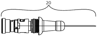
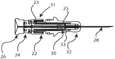
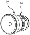
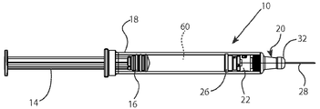
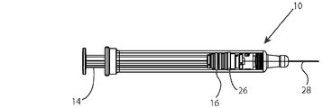
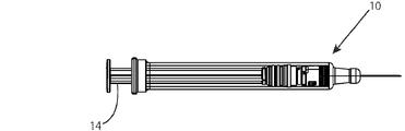
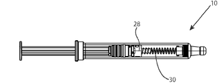
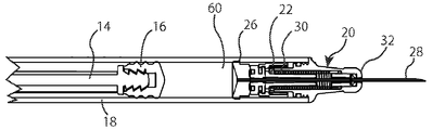
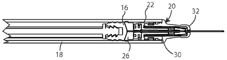
안전 주사기(10)는 배럴(18), 플런저 조립체(12), 및 배럴 어댑터(20)를 포함한다. 주사기 배럴(18)에 장착될 수 있는 배럴 어댑터(20)는 배럴 팁(32), 바늘 조립체(42), 및 바늘 후퇴 메커니즘(21)을 포함한다. 바늘 조립체(42)는 바늘 허브(24), 바늘 시일(26), 및 바늘(28)을 포함하고, 이것은 바늘 조립체(42), 로킹 메커니즘(22), 편향 부재(30), 및 배럴 팁(32)을 통과하도록 구성된다. 로킹 메커니즘(22)의 작동에 의해 편향 부재(30)가 배럴 팁(32) 내로 바늘(28)의 후퇴를 유발하도록, 바늘 후퇴 메커니즘(21)은 편향 부재(30) 및 로킹 메커니즘(22)을 포함한다. 이와 같은 주사기(10)의 조립 방법, 제조 방법, 및 사용 방법이 또한 제공된다.The safety syringe 10 includes a barrel 18, a plunger assembly 12, and a barrel adapter 20. The barrel adapter 20, which can be mounted on the syringe barrel 18, includes a barrel tip 32, a needle assembly 42, and a needle retraction mechanism 21. The needle assembly 42 includes a needle hub 24, a needle seal 26 and a needle 28 which includes a needle assembly 42, a locking mechanism 22, a biasing member 30, 32). The needle withdrawal mechanism 21 moves the biasing member 30 and the locking mechanism 22 in the direction of the arrow A so that the actuation of the locking mechanism 22 causes the biasing member 30 to retract the needle 28 into the barrel tip 32 . A method of assembling, manufacturing, and using the syringe 10 is also provided.

Description
관련 출원의 상호 참조Cross reference of related application
본 출원은 2012년 2월 23일에 출원된 미국 가출원 제 61/602,277 호; 2012년 4월 28일에 출원된 미국 가출원 제 61/639,898 호; 2012년 7월 2일에 출원된 미국 가출원 제 61/667,010 호에 대해 우선권을 주장하고, 이들 출원은 사실상 그 전체가 본 명세서에서 참조로 포함된다.This application is related to U.S. Provisional Application No. 61 / 602,277, filed February 23, 2012; U.S. Provisional Application No. 61 / 639,898, filed April 28, 2012; U.S. Provisional Application No. 61 / 667,010, filed July 2, 2012, the entirety of which is hereby incorporated by reference in its entirety.
발명의 분야Field of invention
본 발명은 안전 주사기에 관한 것이다. 더 구체적으로, 본 발명의 실시형태는 배럴-적합성 바늘 후퇴 시스템, 이와 같은 안전 메커니즘을 결합한 주사기, 이와 같은 안전 주사기를 제조하는 방법, 및 그 사용 방법에 관한 것이다.The present invention relates to a safety syringe. More specifically, embodiments of the present invention relate to a barrel-adapted needle retraction system, a syringe incorporating such a safety mechanism, a method of manufacturing such a safety syringe, and a method of using the same.
손으로 작동되는 사전 충전된 주사기 카트리지는 본 발명의 소유자 및 양수인을 포함하는 다양한 제조자로부터 상업적으로 구입할 수 있다. 사전 충전된 주사기 카트리지는 약물 용액, 약물 현탁액, 백신, 의약 치료제, 및 임의의 다른 비경구 주입에 의한 액체 약제의 투여 시에 사용된다.Hand operated pre-filled syringe cartridges are commercially available from a variety of manufacturers, including the owner and assignee of the present invention. A pre-filled syringe cartridge is used for administration of a drug solution, a drug suspension, a vaccine, a medicament, and any other parenteral injectable liquid medicament.
그러므로, 사전 충전된 주사기 카트리지는 일차적인 약물 챔버, 이 약물 챔버에 영구적으로 고정되고 이 약물 챔버와 유체 연통하는 피하주사 바늘, 및 약물 챔버 내에 슬라이딩 가능하게 수용되는 피스톤을 포함한다. 사전 충전된 주사기 카트리지의 피스톤은 플런저 부분 조립체를 종종 포함하고, 이 플런저 부분 조립체는 바늘로부터 액체 약제를 배출시키기 위한 플런저 내측부 및 플런저 외측부를 포함할 수 있다. 사전 충전된 주사기는 전형적으로 모든 부품 및 약물 용액이 미생물 오염으로부터 격리되는 무균 제조 환경 내에서 약물 및 주사기가 결합되는 무균 충전실 내에서 의약품 회사 또는 무균 충전 청부업자에 의해 제조된다.Thus, a pre-filled syringe cartridge includes a primary drug chamber, a hypodermic needle permanently secured to the drug chamber and in fluid communication with the drug chamber, and a piston slidably received within the drug chamber. The piston of the pre-filled syringe cartridge often includes a plunger subassembly, which may include a plunger inner portion and a plunger outer portion for discharging the liquid medicament from the needle. The pre-filled syringe is typically manufactured by the pharmaceutical company or sterile filling contractor in an aseptic filling chamber where the drug and syringe are joined in a sterile manufacturing environment where all parts and drug solutions are isolated from microbial contamination.
연속적인 사용자들 사이에서 적절한 살균을 행하지 않은 상태로 주사기를 공유하는 관습은 인체 면역결핍 바이러스(HIV) 및 간염의 전염의 주요 원인으로서, 환자에게 후속적인 심각한 영향을 주고, 그리고 환자의 의학적 배려를 지원하고 제공하기 위한 높은 사회적 비용을 초래한다.The practice of sharing syringes without proper sterilization among subsequent users is a major cause of the transmission of human immunodeficiency virus (HIV) and hepatitis, which has a subsequent serious impact on the patient, Resulting in high social costs to support and provide.
더욱이, 의료 전문가는 사용된 주사기에 노출될 수 있고, 이것은 부주의에 의한 바늘 찔림 부상 및 감염성 병원체 또는 기타 오염물에의 노출의 가능성을 초래할 수 있다. 이러한 문제에 따라, 주사기 재사용 및/또는 사용된 주사기에 의한 바늘 찔림 부상을 방지하기 위한 목적으로 후퇴 가능한 주사기가 개발되어 왔다.Moreover, the medical professional can be exposed to the used syringe, which can lead to inadvertent needle pricking and the possibility of exposure to infectious agents or other contaminants. In response to these problems, retractable syringes have been developed for the purpose of reusing syringes and / or preventing needle pricking by used syringes.
이와 같은 후퇴 가능한 주사기의 개발에서, 비교적 복잡한 후퇴 가능한 바늘 조립체가 고안되어 왔고, 이것은 특유의 주사기 배럴 형상 또는 구성을 위해 개발되었고, 상이한 형상 또는 구성을 갖는 주사기 배럴에 쉽게 장착될 수 없다. 이것은 일반적으로 공급이 부족한 유리 주사기 배럴의 경우에 특히 문제인데, 다수의 유리 배럴은 후퇴 가능한 바늘 조립체를 장착하기 위한 원하는 형상 또는 구성을 갖지 않는다. 따라서, 기존의 많은 안전 주사기는 특수 가공된 후퇴 메커니즘 및 배럴 구성을 필요로 하고, 이것은 복잡한 제조 공정 또는 작동 상의 변화를 필요로 할 수 있다. 이와 같은 안전 주사기의 제조 시에 사용되는 재료는 규제당국의 승인을 위한 복잡한 기준에 부합해야 한다. 추가적으로, 안전 주사기는 광범한 채용을 촉진하도록 종래의 주사기와 심미적으로 유사성을 유지해야 하고, 자신이 투여하는 환자를 위해 사용이 편리해야 한다.In the development of such a retractable syringe, relatively complex retractable needle assemblies have been devised, which have been developed for the specific syringe barrel shape or configuration and can not be easily mounted on a syringe barrel having a different shape or configuration. This is a particular problem in the case of glass syringe barrels that are generally in short supply, but many glass barrels do not have the desired shape or configuration for mounting the retractable needle assembly. Thus, many existing safety syringes require specialized machined retraction mechanisms and barrel configurations, which may require complicated manufacturing processes or operational changes. Materials used in the manufacture of such safety syringes must meet the complex criteria for approval by regulatory authorities. In addition, safety syringes must maintain aesthetic similarity with conventional syringes to facilitate widespread adoption and should be easy to use for the patient to whom they are administered.
본 발명의 실시형태는 배럴-적합성 바늘 후퇴 시스템, 이와 같은 안전 메커니즘을 결합한 주사기, 이와 같은 안전 주사기의 제조하는 방법, 및 그 사용 방법에 관한 것이다. 본 발명의 실시형태는 복잡한 제조 공정을 필요로 함이 없이 또는 의약품 회사 또는 계약된 약물 충전 회사를 위한 작동 상의 변화 없이 개선된 사용자 안전성을 위해 신뢰할 수 있는 바늘 후퇴를 제공한다. 추가적으로, 본 발명의 실시형태는 의약품 용도를 위해 쉽게 채용할 수 있는 재료 및 부품을 사용하는 구성을 제공하고, 이들 중 다수는 시판 부품 또는 표준 부품으로서 생각되고 있다. 더욱이, 본 발명은 바늘 후퇴 메커니즘을 갖지 않는 종래의 주사기와 시각적으로 유사하고, 의사 및 자신이 투여하는 환자와 같은 최종 사용자를 위한 인체공학적이고, 그리고 매우 바람직한 집합적 안정성 기구를 제공하는 부품 및 디바이스를 제공한다. 특히 본 발명의 새로운 배럴 어댑터는, 바람직하게, 배럴에 일체형 바늘 조립체 및 후퇴 메커니즘을 제공하는 직선상-배럴, 유리 배럴과 같은 다양한 구성 및 재료의 일차 약물 배럴에 적합화될 수 있다. 이와 같은 실시형태는 사전 충전된 약물 주사기 또는 사용 시 충전되는 주입 가능한 약물 주사기를 위해 사용될 수 있다. 그러므로, 본 발명의 적합성 후퇴 메커니즘은 직선상-유리 배럴과 같은 표준 배럴에 고정 상태로 부착되거나, 첨부되거나, 장착되거나, 아니면 결합될 수 있다. 따라서, 이들 실시형태는 약물 충전 공정에 쉽게 통합되는 새롭고 비용 효율적인 부품 및 디바이스를 제공한다. Embodiments of the present invention relate to a barrel-adapted needle retraction system, a syringe incorporating such a safety mechanism, a method of manufacturing such a safety syringe, and a method of using the same. Embodiments of the present invention provide a reliable needle retraction for improved user safety without requiring complex manufacturing processes or operational changes for pharmaceutical companies or contracted drug filling companies. In addition, embodiments of the present invention provide configurations using materials and components that are readily adoptable for pharmaceutical applications, many of which are thought of as commercial or standard components. Moreover, the present invention provides components and devices that are visually similar to conventional syringes that do not have a needle retraction mechanism and that provide ergonomic and highly desirable collective stability mechanisms for end users such as physicians and patients to whom they are administering Lt; / RTI > In particular, the novel barrel adapter of the present invention can preferably be adapted to a primary drug barrel of various configurations and materials, such as a rectilinear-barrel, glass barrel, which provides an integral needle assembly and retraction mechanism in the barrel. Such an embodiment may be used for pre-filled drug syringes or injectable drug syringes that are filled in use. Therefore, the conformity retraction mechanism of the present invention can be fixedly attached, attached, mounted, or otherwise coupled to a standard barrel, such as a straight-on glass barrel. Thus, these embodiments provide new and cost effective components and devices that are easily integrated into the drug filling process.
본 발명의 실시형태의 하나의 양태에서, 배럴(berrel) 및 이 배럴 내에서 이동하도록 구성되는 플런저 조립체(plunger assembly)를 갖는 안전 주사기를 위한 배럴 어댑터(berrel adapter)가 제공된다. 이러한 배럴 어댑터는 배럴의 원위 단부와 밀봉 가능하게 맞물리도록 구성되는 배럴 팁, 바늘 조립체, 및 바늘 후퇴 메커니즘을 포함한다. 바늘 조립체는 바늘, 바늘이 관통 연장되는 바늘 허브, 및 바늘 시일을 포함한다. 바늘 조립체는 배럴 팁 내에 적어도 부분적으로 배치되고, 그리고 바늘이 배럴 팁의 원위 단부로부터 연장되는 주입 위치로부터 바늘이 배럴 팁 또는 배럴 중 적어도 하나 내에 배치되는 후퇴 위치로 이동하도록 구성된다. 바늘 후퇴 메커니즘은 편향 부재 및 작동 가능한 로킹 장치를 포함한다. 로킹 장치는, 로킹 장치가 로킹되었을 때 편향 부재를 활성화된 위치에 유지하도록, 그리고 작동되었을 때 편향 부재를 해제시키도록 배치된다. 로킹 장치는 플런저 조립체의 누름에 의해 작동될 수 있고, 편향 부재는 이 편향 부재가 활성화된 위치로부터 해제될 때 주입 위치로부터 후퇴 위치로 바늘을 이동시키도록 배치된다. In one aspect of an embodiment of the present invention, a berrel adapter is provided for a safety syringe having a barrel and a plunger assembly configured to move within the barrel. The barrel adapter includes a barrel tip, a needle assembly, and a needle retraction mechanism configured to sealingly engage the distal end of the barrel. The needle assembly includes a needle, a needle hub through which the needle extends, and a needle seal. The needle assembly is configured to be at least partially disposed within the barrel tip and configured to move from an injection position in which the needle extends from the distal end of the barrel tip to a retracted position in which the needle is disposed within at least one of the barrel tip or barrel. The needle retraction mechanism includes a biasing member and an actuatable locking device. The locking device is arranged to hold the biasing member in the activated position when the locking device is locked, and to release the biasing member when actuated. The locking device can be actuated by the pushing of the plunger assembly and the biasing member is arranged to move the needle from the injection position to the retracted position when the biasing member is released from the activated position.
본 발명의 실시형태의 추가의 양태에서, 원위 단부 및 근위 단부를 갖는 배럴, 상기 배럴 내에서 이동하도록 구성되는 플런저 조립체, 및 상기 배럴의 원위 단부와 밀봉 가능하게 맞물리는 배럴 어댑터를 포함하는 자동적으로 후퇴 가능한 안전 주사기가 제공된다. 이러한 배럴 어댑터는 배럴의 원위 단부와 밀봉 가능하게 맞물리도록 구성되는 배럴 팁, 바늘 조립체, 및 바늘 후퇴 메커니즘을 포함한다. 바늘 조립체는 바늘, 바늘이 관통 연장되는 바늘 허브, 및 바늘 시일을 포함한다. 바늘 조립체는 배럴 팁 내에 적어도 부분적으로 배치되고, 그리고 바늘이 배럴 팁의 원위 단부로부터 연장되는 주입 위치로부터 바늘이 배럴 팁 또는 배럴 중 적어도 하나 내에 배치되는 후퇴 위치로 이동하도록 구성된다. 바늘 후퇴 메커니즘은 편향 부재 및 작동 가능한 로킹 장치를 포함한다. 로킹 장치는, 로킹 장치가 로킹되었을 때 편향 부재를 활성화된 위치에 유지하도록, 그리고 작동되었을 때 편향 부재를 해제시키도록 배치된다. 로킹 장치는 플런저 조립체의 누름에 의해 작동될 수 있고, 편향 부재는 이 편향 부재가 활성화된 위치로부터 해제될 때 주입 위치로부터 후퇴 위치로 바늘을 이동시키도록 배치된다. In a further aspect of an embodiment of the present invention there is provided a device for automatically delivering a barrel comprising a barrel having a distal end and a proximal end, a plunger assembly configured to move within the barrel, and a barrel adapter sealingly engaged with the distal end of the barrel A retractable safety syringe is provided. The barrel adapter includes a barrel tip, a needle assembly, and a needle retraction mechanism configured to sealingly engage the distal end of the barrel. The needle assembly includes a needle, a needle hub through which the needle extends, and a needle seal. The needle assembly is configured to be at least partially disposed within the barrel tip and configured to move from an injection position in which the needle extends from the distal end of the barrel tip to a retracted position in which the needle is disposed within at least one of the barrel tip or barrel. The needle retraction mechanism includes a biasing member and an actuatable locking device. The locking device is arranged to hold the biasing member in the activated position when the locking device is locked, and to release the biasing member when actuated. The locking device can be actuated by the pushing of the plunger assembly and the biasing member is arranged to move the needle from the injection position to the retracted position when the biasing member is released from the activated position.
본 발명의 실시형태의 다른 양태에서, 자동적으로 후퇴가능한 안전 주사기를 조립하는 방법이 제공된다. 이러한 방법은 배럴 내에서 이동하도록 플런저 조립체를 배치하는 단계, 상기 배럴의 원위 단부와 배럴 팁을 밀봉 가능하게 맞물리는 단계, 바늘 조립체의 바늘이 상기 배럴 팁으로부터 연장되는 주입 위치와 상기 바늘이 상기 배럴 팁 및 상기 배럴 중 적어도 하나 내에 배치되는 후퇴 위치 사이에서 이동하도록 상기 배럴 팁과 상기 배럴 내에 상기 바늘 조립체를 배치하는 단계, 및 상기 배럴 내에, 편향 부재 및 작동 가능한 로킹 장치를 포함하는 바늘 후퇴 메커니즘을 배치하는 단계를 포함한다. 로킹 장치는, 로킹 장치가 로킹되었을 때 편향 부재를 활성화된 위치에 유지하도록, 그리고 작동되었을 때 편향 부재를 해제시키도록 배치된다. 로킹 장치는 플런저 조립체의 누름에 의해 작동될 수 있고, 편향 부재는 이 편향 부재가 활성화된 위치로부터 해제될 때 주입 위치로부터 후퇴 위치로 바늘을 이동시키도록 배치된다. In another aspect of the present invention, a method of assembling an automatically retractable safety syringe is provided. The method includes the steps of disposing the plunger assembly to move within the barrel, sealingly engaging the barrel tip with the distal end of the barrel, injecting the needle into the barrel tip, Disposing the needle assembly within the barrel tip and the barrel to move between a tip and a retracted position disposed within at least one of the barrel, the needle assembly including a needle retraction mechanism including a biasing member and an actuatable locking device within the barrel And the like. The locking device is arranged to hold the biasing member in the activated position when the locking device is locked, and to release the biasing member when actuated. The locking device can be actuated by the pushing of the plunger assembly and the biasing member is arranged to move the needle from the injection position to the retracted position when the biasing member is released from the activated position.
제 1 특정의 실시형태에서, 본 발명은 주사기 배럴에 대한 바늘 조립체의 장착을 촉진하고 바늘 후퇴 메커니즘을 포함하는 배럴 어댑터를 제공한다. 배럴 어댑터는 배럴 팁, 편향 부재, 로킹 메커니즘, 및 바늘 조립체를 포함한다. 바늘 조립체는 일반적으로 바늘, 바늘 허브, 및 바늘 시일을 포함할 수 있다. 바늘의 하나의 단부는 배럴의 내부에 위치되도록, 그리고 바늘의 다른 하나의 단부는 배럴 팁 내의 개구를 통과하도록, 바늘은 바늘 조립체, 로킹 메커니즘, 편향 부재, 및 배럴 팁을 관통하도록 구성된다. 일부의 실시형태에서, 바늘 허브 및 바늘 시일은 하나의 부품일 수 있고, 한편 다른 실시형태에서 이들은 2 개 이상의 부품을 포함할 수 있다. 예를 들면, 하나의 실시형태에서, 바늘 허브 및 바늘 시일은 듀얼-샷(dual-shot) 플라스틱 바늘 허브 및 탄성중합체 바늘 시일과 같은 단일화된 유닛이다. 바늘 허브 및/또는 바늘 시일과 같은 바늘 조립체의 양태는 바늘을 파지하기 위해 사용될 수 있다. 바늘의 파지는 기계적 파지, 이하에서 더 설명하는 바와 같은 주조식 파지, 또는 본 기술분야에 공지된 다수의 다른 파지 방법에 의해 달성될 수 있다. 대안적으로, 바늘 조립체가 아닌 부품 또는 바늘 조립체의 부품에 추가되는 부품이 바늘을 파지하기 위해 사용될 수 있다. 적어도 하나의 실시형태에서, 로킹 메커니즘은 실질적으로 고정된 위치에 바늘을 파지하도록 기능하고, 동시에 배럴 어댑터 및 안전 주사기는 일반적으로 약물 주입을 위해 구성되는 최초 단계에 있다. 적어도 하나의 실시형태에서, 로킹 메커니즘은 로킹 메커니즘과 맞물리는 배럴 팁 상에 인터페이스를 포함할 수 있다. 사용자에 의한 활성화 시, 바늘 허브는 배럴 팁과의 로킹 메커니즘의 맞물림으로부터 로킹 메커니즘의 해제를 개시하기 위해 사용될 수 있다. 배럴 팁으로부터 로킹 메커니즘을 해제시키는 것에 의해 편향 부재는 팽창이 허용되고, 그 결과 바늘 조립체를 실질적으로 배럴의 종축선을 따라 근위 방향으로 후퇴시킨다. 로킹 메커니즘의 해제 및 근위 방향으로 편향된 편향 부재의 활성화 시에, 본 발명의 일부의 실시형태에서는 전체 바늘 조립체가 후퇴되고, 한편 다른 실시형태에서는 바늘을 포함하는 그 특정 부품만이 후퇴된다. 유사하게, 본 발명의 일부의 실시형태에서, 로킹 메커니즘은 바늘 조립체와 함께 후퇴되고, 다른 실시형태에서, 로킹 메커니즘은 실질적으로 고정 상태를 유지하지만 바늘 조립체 또는 그 부품은 이동할 수 있다. In a first particular embodiment, the present invention provides a barrel adapter that facilitates mounting of a needle assembly to a syringe barrel and includes a needle retraction mechanism. The barrel adapter includes a barrel tip, a biasing member, a locking mechanism, and a needle assembly. The needle assembly may generally include a needle, a needle hub, and a needle seal. The needle is configured to penetrate the needle assembly, the locking mechanism, the biasing member, and the barrel tip so that one end of the needle is positioned inside the barrel and the other end of the needle passes through the opening in the barrel tip. In some embodiments, the needle hub and needle seal may be a single part, while in other embodiments they may include two or more parts. For example, in one embodiment, the needle hub and needle seal are a unitized unit such as a dual-shot plastic needle hub and an elastomeric needle seal. Embodiments of needle assemblies such as needle hubs and / or needle seals may be used to grasp needles. The grasping of the needles can be accomplished by mechanical grasping, by a grasping grip as described further below, or by a number of other grasping methods known in the art. Alternatively, a component that is not a needle assembly or that is added to a component of the needle assembly may be used to grasp the needle. In at least one embodiment, the locking mechanism serves to grasp the needle in a substantially fixed position, while at the same time the barrel adapter and the safety syringe are generally in the initial stages of being configured for drug injection. In at least one embodiment, the locking mechanism may include an interface on the barrel tip that engages the locking mechanism. Upon activation by the user, the needle hub may be used to initiate release of the locking mechanism from engagement of the locking mechanism with the barrel tip. By releasing the locking mechanism from the barrel tip, the biasing member is allowed to expand, thereby retracting the needle assembly substantially in the proximal direction along the longitudinal axis of the barrel. Upon release of the locking mechanism and activation of the biasing member biased in the proximal direction, the entire needle assembly is retracted in some embodiments of the present invention, while in other embodiments only that particular component, including the needle, is retracted. Similarly, in some embodiments of the present invention, the locking mechanism is retracted with the needle assembly, while in other embodiments the locking mechanism remains substantially stationary, but the needle assembly or parts thereof can move.
따라서, 배럴 어댑터는 바늘 유지 및 후퇴를 위해 필요한 부품을 포함하고, 그리고 표준 배럴과 결합되도록 구성된다. 배럴 어댑터는 다수의 공지된 방법을 통해 배럴의 원위 단부에 결합되어 부착되도록 구성된다. 적어도 하나의 실시형태에서, 배럴 어댑터는 유리의 직선상-배럴과 같은 (예를 들면, 배럴의 적어도 하나의 원위 부분을 따라 실질적으로 평행한) 실질적으로 직선상의 단면 프로파일을 갖는 배럴과 결합하도록 구성된다. 배럴 어댑터는 다수의 상이한 방식으로 배럴과 결합하도록 구성될 수 있다. 그러나, 하나의 바람직한 실시형태에서, 배럴 어댑터는 적어도 하나의 근위 연결 부분이 배럴의 원위 부분의 내경에 장착되도록, 그리고 배럴의 원위 부분의 내경 내에 위치하도록 형성되는 방식으로 구성된다. 그러므로, 배럴 어댑터는 배럴의 원위 단부에 삽입 및 부착시키거나, 첨부시키거나, 장착시키거나, 또는 아니면 결합시킴으로써 표준 직선상-배럴 약물 챔버에 연결될 수 있다. 이것에 의해 배럴 어댑터는 모든 유형의 배럴, 특히 표준 유리의 직선상-배럴에 유연하게 적합화될 수 있고, 그 결과 제조 상의 장점이 제공될 수 있고, 작동 비용이 절약될 수 있다. 그러므로, 본 발명의 배럴 어댑터는 통합된 바늘 안전성 특징을 갖는 주사기를 제조하기 위한 표준 배럴과 바늘 후퇴 메커니즘의 조립을 단순화시킨다. 배럴 어댑터의 이들 실시형태 중 임의의 실시형태에서, 편향 부재는 일반적으로 배럴 팁 내에 고정 상태로 또는 이동 가능한 상태로 장착된다. 편향 부재는 근위 방향 내에서 그리고 실질적으로 배럴의 종축선을 따라 확장되도록 편향된다. Thus, the barrel adapter includes the necessary parts for needle retention and retraction, and is configured to engage a standard barrel. The barrel adapter is configured to be coupled and attached to the distal end of the barrel via a number of known methods. In at least one embodiment, the barrel adapter is configured to engage a barrel having a substantially linear cross-sectional profile, such as a linear-barrel of glass (e.g., substantially parallel along at least one distal portion of the barrel) do. The barrel adapter may be configured to couple with the barrel in a number of different ways. However, in one preferred embodiment, the barrel adapter is configured in such a way that at least one proximal connecting portion is mounted to the inside diameter of the distal portion of the barrel, and is configured to be positioned within the inside diameter of the distal portion of the barrel. Thus, the barrel adapter may be connected to a standard straight-on-barrel drug chamber by inserting and attaching, attaching, mounting, or otherwise engaging the distal end of the barrel. This allows the barrel adapter to be flexibly adapted to all types of barrels, in particular to the linear-barrel of standard glass, and as a result, manufacturing advantages can be provided and operating costs can be saved. Therefore, the barrel adapter of the present invention simplifies the assembly of the standard barrel and needle retraction mechanism for manufacturing syringes with integrated needle safety features. In any of these embodiments of the barrel adapter, the biasing member is generally mounted in a fixed or movable state within the barrel tip. The biasing member is biased to extend within the proximal direction and substantially along the longitudinal axis of the barrel.
본 발명의 배럴 어댑터에 의해 표준 배럴을 갖는 다양한 바늘 조립체의 선택 및 구성이 가능해진다. 다시 말하면, 본 발명의 설계 및 구성에 의해 사용자는 특정의 설계 또는 치수의 바늘 및/또는 바늘 조립체를 선택할 수 있고, 이것을 약물 전달용 주사기 배럴에 적합화시킬 수 있다. 따라서, 본 발명의 배럴 어댑터는 사용자에 의한 약물 전달 디바이스의 추가의 특별 주문 생산(customization)을 가능하게 하고, 사용자 또는 의약품 제조회사는 안전 주사기를 제조하기 위해 임의의 배럴에 결합식 배럴 어댑터의 후퇴 메커니즘을 사용할 수 있다. 예를 들면, 배럴 어댑터 및 바늘 조립체는 다수의 상이한 바늘 길이를 제공하도록 구성될 수 있다. 그러면 사용자는 자신이 원하는 바늘 길이를 갖는 배럴 어댑터를 선택할 수 있고, 이것을 약물을 전달하기 위한 주사기에 적합화시킬 수 있다. 본 발명의 이러한 유연성은 피하 또는 근육 내의 약물 전달의 경우에 특히 유용하다. 본 발명의 배럴 어댑터는 이러한 유연성이 가능하도록 구성될 수 있다. 이러한 적합식 특징을 제공하기 위해 하나 이상의 추가의 부품이 사용될 수 있다. 예를 들면, 배럴에 배럴 어댑터의 배럴 팁을 연결하기 위해 하나 이상의 연결 부품이 사용될 수 있다. 이와 같은 실시형태에서, 하나의 연결 부품(예를 들면, 수용 부품)이 유리 배럴의 원위 단부 상에 고정 상태로 장착될 수 있다. 수용 부품은 일체형 후퇴 메커니즘을 구비하는 배럴 팁을 직접적으로 수용 및 맞물릴 수 있다. 대안적으로, 배럴 어댑터는 수용 부품과의 맞물림을 위해 사용되는 하나 이상의 추가의 연결 부품(예를 들면, 결합 부품)을 포함할 수 있다. 본 기술분야의 당업자에게 공지된 탄성중합체 시일과 같은 다른 선택적 부품이 필요할 수 있고, 그리고 배럴 어댑터와 배럴 사이의 연결을 촉진시키기 위해 상기 디바이스 내에 결합될 수 있다. The barrel adapter of the present invention makes it possible to select and configure various needle assemblies having standard barrels. In other words, the design and construction of the present invention allows the user to select a needle and / or needle assembly of a particular design or dimension and adapt it to the drug delivery syringe barrel. Thus, the barrel adapter of the present invention allows for additional customization of the drug delivery device by the user, and the user or drug manufacturer can place the barrel adapter into any barrel for retraction of the barrel adapter Mechanism can be used. For example, the barrel adapter and needle assembly may be configured to provide a number of different needle lengths. The user can then select the barrel adapter having the desired needle length and adapt it to the syringe to deliver the drug. This flexibility of the present invention is particularly useful in the case of subcutaneous or intramuscular drug delivery. The barrel adapter of the present invention can be configured to allow such flexibility. One or more additional components may be used to provide such a conforming feature. For example, one or more connecting parts may be used to connect the barrel tip of the barrel adapter to the barrel. In such an embodiment, one connecting part (e.g., a receiving part) can be fixedly mounted on the distal end of the glass barrel. The receiving component can directly receive and engage the barrel tip with an integral retraction mechanism. Alternatively, the barrel adapter may include one or more additional connecting parts (e. G., Mating parts) used for engagement with the receiving part. Other optional components, such as an elastomeric seal known to those skilled in the art, may be required and may be coupled within the device to facilitate connection between the barrel adapter and the barrel.
추가적으로, 본 발명의 배럴 어댑터는 치료적 유체 또는 약물과 실질적으로 비반응성이고 의약품 등급의 용도에서 사용하기에 적절한 재료를 사용한다. 새로운 배럴 어댑터는 특정 플라스틱과 같은 분해성 재료와 치료적 유체 또는 약물 사이의 접촉 또는 상호작용의 가능성을 최소화하거나 제거하도록 구성된다. 적합성 바늘 파지 및 후퇴 메커니즘을 갖는 배럴 어댑터는 또한 일차적인 약물 챔버로부터 환자로의 바늘을 통한 유체 경로를 제공하고, 이 경로에는 분해성 재료가 실질적으로 존재하지 않는다. 이와 같은 새로운 어댑터 구성은, 본 발명의 새로운 안전 주사기를 제공하기 위해 배럴 내에 결합되었을 때, 약물 및 약물 전달 디바이스에 향상된 안전성 및 보관 수명 파라미터를 제공한다. 이러한 특성은 일반적으로 모든 의약품 치료에 대해 매우 바람직한 것으로 생각되지만, 생물학 및 기타 복잡한 치료에서 사용하기 위한 주사기에서 특히 유리할 수 있다. 하나의 실시형태에서, 약물 유체 경로가 오로지 유리, 탄성중합체, 및 금속만을 포함하도록(그리고 약물이 오로지 유리, 탄성중합체, 및 금속에만 접촉하도록), 예를 들면, 금속 바늘은, 바늘의 근위 단부에서는 탄성중합체 바늘 시일에 의해 그리고 바늘 시일에 대해 원위에 위치하는 바늘의 부분에서는 플라스틱 배럴 팁의 개구에 의해, 유리 배럴 내에 파지된다. 이러한 방식으로, 약물은 약물 챔버로부터 환자에 이르기까지 어떤 플라스틱과도 접촉함이 없이 이동된다. 다른 실시형태에서, 약물 유체 경로용으로 다른 재료의 조합 또는 더 적은 수의 재료가 사용될 수 있다. In addition, the barrel adapter of the present invention employs materials that are substantially non-reactive with the therapeutic fluid or drug and suitable for use in pharmaceutical grade applications. The new barrel adapter is configured to minimize or eliminate the possibility of contact or interaction between the degradable material, such as certain plastics, and the therapeutic fluid or drug. The barrel adapter with compliance needle retraction and retraction mechanism also provides a fluid path through the needle from the primary drug chamber to the patient, which path is substantially free of degradable material. This new adapter configuration provides improved safety and shelf life parameters for drug and drug delivery devices when coupled into a barrel to provide a novel safety syringe of the present invention. While these properties are generally considered highly desirable for all drug treatments, they may be particularly advantageous in syringes for use in biology and other complex treatments. In one embodiment, for example, the metal needles can be positioned such that the drug fluid path includes solely glass, elastomer, and metal (and the drug only contacts glass, elastomer, and metal) Is held in the glass barrel by the elastomeric needle seal and by the opening of the plastic barrel tip in the part of the needle located on the circle against the needle seal. In this way, the drug is transferred without any plastic contact from the drug chamber to the patient. In other embodiments, a combination of different materials or fewer materials may be used for the drug fluid path.
또한 본 발명의 실시형태는 일체형 바늘 파지 및 후퇴 메커니즘을 위해 필요한 부품의 수를 실질적으로 감소시킨다. 본 발명의 적어도 하나의 실시형태에서, 예를 들면, 배럴 어댑터는 종래의 바늘 홀더 또는 바늘-오버-몰드(needle-over-mold)(예를 들면, 약물 주입을 위해 배럴 내에 바늘의 파지를 도와 주기 위해, 그리고 대안적으로 또는 추가적으로 주입 후 바늘의 후퇴를 도와 주기 위해, 바늘 상에 형성되는 재료)를 필요로 하지 않는다. 이와 같은 부품의 제거는 분해성 재료와 약물의 상호작용의 가능성을 더 감소시킬 수 있고, 동시에 잠재적인 제조 상의 이점 및 조작상 비용 절약이 유발된다. 본 발명의 일부의 실시형태에서 부품의 감소는 다중 기능용의 특정 부품을 사용함으로써 달성될 수 있다. Embodiments of the present invention also substantially reduce the number of components required for integral needle retention and retraction mechanisms. In at least one embodiment of the present invention, for example, a barrel adapter may be used in a conventional needle holder or needle-over-mold (e.g., to assist in gripping the needle in the barrel for drug ingestion , And, alternatively or additionally, the material formed on the needles to assist in retraction of the needle after injection). Removal of such parts can further reduce the likelihood of interaction of the degradable material with the drug, while at the same time resulting in potential manufacturing advantages and operational cost savings. In some embodiments of the present invention, reduction of parts can be achieved by using specific components for multiple functions.
다른 실시형태에서, 본 발명은 배럴, 플런저 조립체 및 배럴 어댑터를 포함하는 안전 주사기를 제공한다. 배럴 어댑터는 배럴 팁, 편향 부재, 로킹 메커니즘, 및 바늘 조립체를 포함한다. 바늘 조립체는 일반적으로 바늘, 바늘 허브, 및 바늘 시일을 포함할 수 있다. 바늘의 하나의 단부는 배럴의 내부에 위치되도록, 그리고 바늘의 다른 하나의 단부는 배럴 팁 내의 개구를 통과하도록, 바늘은 바늘 조립체, 로킹 메커니즘, 편향 부재, 및 배럴 팁을 관통하도록 구성된다. 배럴은 그 종축선을 따라 약물 주입을 위한 원위 단부, 주입 제어를 위한 근위 단부, 및 약물 수용을 위한 배럴 내부의 적어도 일부를 갖는 실질적으로 원통상일 수 있다. 배럴 어댑터는 다수의 공지된 방법을 통해 배럴의 원위 단부에 결합되어 부착되도록 구성된다. 배럴 어댑터는 안전 주사기의 배럴과 결합할 수 있거나, 또는 안전 주사기의 배럴에 장착될 수 있거나, 또는 안전 주사기의 배럴과 맞물릴 수 있다. 배럴 어댑터의 이들 실시형태 중 임의의 실시형태에서, 일반적으로 편향 부재는 배럴 팁과 배럴의 원위 단부 내에 고정 상태로 또는 이동 가능한 상태로 장착된다. 편향 부재는 근위 방향 내에서 그리고 실질적으로 배럴의 종축선을 따라 확장되도록 편향된다. 플런저 조립체는 플런저 로드 및 플런저 스토퍼 또는 시일을 포함할 수 있다. 플런저 로드는, 예를 들면, 플런저 시일에의 나사 체결과 같은 다수의 상이한 연결부에 의해 플런저 시일에 연결될 수 있다. 플런저 조립체는 배럴의 근위 단부에 장착될 수 있고, 배럴 어댑터는 배럴의 원위 단부에 장착될 수 있다. 플런저 시일은 탄성중합체 재료를 포함할 수 있고, 용기의 완전성을 갖는 무균 약물 챔버를 유지하도록 배럴의 내경과 억지끼워맞춤을 제공하는 크기를 가질 수 있다. 플런저 시일은 또한 예를 들면, 플런저 시일이 배럴 내의 위치로 눌려짐에 따라 약물 챔버로부터 공기를 제거할 수 있는 축방향 관통공과 같은 개구를 포함할 수 있다. 플런저 시일 개구는 플런저 로드와의 연결에 의해 폐쇄되거나 캐핑(capping)될 수 있고, 플런저 로드는 플런저 시일 개구 내로 나사체결될 수 있다. In another embodiment, the present invention provides a safety syringe comprising a barrel, a plunger assembly, and a barrel adapter. The barrel adapter includes a barrel tip, a biasing member, a locking mechanism, and a needle assembly. The needle assembly may generally include a needle, a needle hub, and a needle seal. The needle is configured to penetrate the needle assembly, the locking mechanism, the biasing member, and the barrel tip so that one end of the needle is positioned inside the barrel and the other end of the needle passes through the opening in the barrel tip. The barrel may be substantially cylindrical with a distal end for drug injection along its longitudinal axis, a proximal end for injection control, and at least a portion of the interior of the barrel for receiving the drug. The barrel adapter is configured to be coupled and attached to the distal end of the barrel via a number of known methods. The barrel adapter may engage the barrel of the safety syringe, or it may be mounted on the barrel of the safety syringe, or may engage the barrel of the safety syringe. In any of these embodiments of the barrel adapter, the biasing member is generally mounted in a stationary or movable manner within the distal end of the barrel tip and barrel. The biasing member is biased to extend within the proximal direction and substantially along the longitudinal axis of the barrel. The plunger assembly may include a plunger rod and a plunger stopper or seal. The plunger rod may be connected to the plunger seal by a number of different connections, such as, for example, screwing to a plunger seal. The plunger assembly can be mounted to the proximal end of the barrel, and the barrel adapter can be mounted to the distal end of the barrel. The plunger seal may comprise an elastomeric material and may have a size to provide an inner diameter and interference fit of the barrel to maintain a sterile drug chamber having integrity of the container. The plunger seal may also include an opening, such as an axial through-hole, for example, that can remove air from the drug chamber as the plunger seal is depressed into position within the barrel. The plunger seal opening can be closed or capped by connection with the plunger rod and the plunger rod can be screwed into the plunger seal opening.
하나 이상의 본 발명의 실시형태는 특정의 표준 부품을 선택적으로 포함할 수 있다. 예를 들면, 본 발명의 배럴 어댑터 구성 및 주사기 디바이스는 하나 이상의 O링을 포함할 수 있다. 적어도 하나의 실시형태에서, 배럴 내에서 배럴 팁을 밀봉하기 위해 및/또는 배럴의 약물 챔버 내의 무균 환경 및 용기의 완전성을 보장하기 위해 하나 이상의 O링이 사용된다. 추가적으로 또는 대안적으로, 배럴 어댑터는 후퇴율의 제어를 촉진하기 위한 하나 이상의 제어 부재를 포함할 수 있다. 유사하게, 배럴 어댑터는 클립, 플랩(flap), 플랜지, 등과 같은 하나 이상의 바늘 블록을 포함할 수 있고, 이것은 후퇴 메커니즘이 개시된 후 또는 완료된 후에 바늘이 배럴 팁의 개구를 통해 배럴로부터 외부로 병진운동되거나 돌출하는 것을 방지하는 기능을 발휘한다. 더욱이, 안전 주사기는 심미성, 사용상의 편리성, 또는 다른 목적을 위한 하나 이상의 부품을 포함할 수 있다. 예를 들면, 하나 이상의 본 발명의 실시형태는 핑거 플랜지를 포함할 수 있다. One or more embodiments of the invention may optionally include certain standard components. For example, the barrel adapter arrangement and syringe device of the present invention may include one or more O-rings. In at least one embodiment, one or more O-rings are used to seal the barrel tip within the barrel and / or to ensure integrity of the aseptic environment and vessel within the drug chamber of the barrel. Additionally or alternatively, the barrel adapter may include one or more control members to facilitate control of the rate of retraction. Similarly, the barrel adapter may include one or more needle blocks, such as clips, flaps, flanges, etc., which allow the needle to be translated from the barrel outward through the opening of the barrel tip after or after the retraction mechanism is initiated Or protruding from the surface. Moreover, the safety syringe may include one or more components for aesthetics, ease of use, or other purposes. For example, one or more embodiments of the present invention may include a finger flange.
본 발명의 새로운 배럴 어댑터 설계는 이것에 바늘 조립체를 장착하기 위한 특정의 배럴 형상 또는 구성을 가질 필요성을 제거한다. 본 발명의 다른 바람직한 특징은 더 적은 수의 부품을 포함하는 비교적 단순화된 바늘 조립체를 제공하는 것으로서, 이것에 의해 사용자 친화적이고 안전한 후퇴가능한 주사기를 제공함과 동시에 제조 비용을 최소로 유지하고 및/또는 후퇴가능한 주사기의 매스 분배(mass distribution)를 촉진한다. 본 발명의 실시형태는 또한 표준적인 상업적으로 구입가능한 부품의 사용을 가능하게 하는 구성을 제공하고, 이것에 의해 전체적인 제조 비용이 감소되고, 조립공정이 효율화되고, 그리고 비표준 재료 및 부품과 종종 관련되는 조절상의 문제가 방지될 수 있다. 추가적으로, 본 발명은 유체 용량의 효율적인 전달을 제공하고, 이것에 의해 유체 용량의 손실을 최소화하고, 및/또는 주사기 재사용 및/또는 바늘 찔림 부상을 방지하거나 적어도 최소화하도록 하나 이상의 로킹 시스템을 장착한다. The novel barrel adapter design of the present invention eliminates the need to have a specific barrel shape or configuration for mounting the needle assembly thereto. Another desirable feature of the present invention is to provide a relatively simplified needle assembly that includes fewer components, thereby providing a user-friendly and secure retractable syringe while at the same time keeping the manufacturing cost to a minimum and / Thereby facilitating the mass distribution of the possible syringes. Embodiments of the present invention also provide a configuration that enables the use of standard commercially available components, thereby reducing overall manufacturing costs, streamlining the assembly process, and reducing the cost associated with non-standard materials and components Adjustment problems can be avoided. Additionally, the present invention implements one or more locking systems to provide efficient delivery of fluid capacity, thereby minimizing loss of fluid capacity and / or preventing or at least minimizing needle re-use and / or needle sticking.
따라서, 또는 다른 실시형태에서, 본 발명은 배럴 어댑터, 플런저 조립체, 종축선을 갖는 배럴을 갖는 안전 주사기를 조립하기 위한 방법을 제공한다. 본 방법은 배럴 팁, 편향 부재, 로킹 메커니즘 및 바늘 조립체를 포함하는 배럴 어댑터를 조립하는 단계; 배럴의 원위 단부에 배럴 팁을 장착하는 단계; 및 배럴의 근위 단부에 플런저 시일 및 플런저 로드를 갖는 플런저 조립체를 장착하는 단계를 포함한다. 배럴 어댑터는 배럴의 원위 단부에, 예를 들면, 접착제에 의해 고정 상태로 부착될 수 있다. 플런저 조립체는 먼저 배럴 내에 플런저 시일을 삽입한 다음 나사 연결 또는 다른 공지된 연결 방법으로 플런저 로드를 플런저 시일에 삽입함으로써 배럴의 원위 단부에 이동 가능하게 장착될 수 있다. 안전 주사기를 조립하기 위한 방법은, 상기 배럴 팁을 장착하는 단계 후, 그러나 상기 플런저 조립체를 장착하는 단계 전, 배럴에 약물을 충전하는 단계를 더 포함한다. 적어도 하나의 실시형태에서, 배럴 어댑터는 배럴 내에 장착되기 전에 압축된 구성을 갖는다. 예를 들면, 편향 부재는, 예를 들면, 활성화된 단계에서, 배럴 내에 배럴 어댑터를 장착하기 전에 로킹 메커니즘과 배럴 팁 사이에 압축 상태로 맞물릴 수 있다. 다른 실시형태에서, 이러한 부품은 편향 부재를 압축하여 정위치에 로킹시키기 전에 배럴 내에 장착될 수 있다. 따라서, 본 방법은 편향 부재를 압축시키는 단계 및 배럴 어댑터를 배럴에 장착한 후 맞물린 그리고 활성화된 위치로 로킹 메커니즘을 로킹시키는 단계를 더 포함할 수 있다. 일부의 실시형태에서 플런저 조립체는 편향 부재를 압축시키기 위해, 그리고 로킹 메커니즘을 로킹시키기 위해 사용될 수 있다는 것이 고찰된다. 일부의 실시형태에서, 예를 들면, 사전충전식 안전 주사기 구성에서, 플런저 조립체의 적어도 일부는 충전 공정을 촉진하기 위해 제거될 수 있다. 예를 들면, 플런저 로드는 제거될 수 있으나, 플런저 시일은 충전 공정을 위해 배럴 내에 파지될 수 있다. 다른 실시형태에서, 예를 들면, 사용시 충전하는 구성에서, 플런저 조립체는 안전 주사기의 배럴 내에 파지될 수 있고, 배럴 어댑터를 통해, 구체적으로는 바늘 조립체를 통해 배럴의 충전을 촉진하기 위한 근위 방향으로 인출될 수 있다. 통상 전문가에 의해 인정되는 바와 같이, 약물은 용액, 분말, 현탁액 등, 또는 이들의 임의의 조합물일 수 있다. Thus, or in another embodiment, the present invention provides a method for assembling a safety syringe having a barrel adapter, a plunger assembly, a barrel having a longitudinal axis. The method includes the steps of assembling a barrel adapter including a barrel tip, a biasing member, a locking mechanism and a needle assembly; Mounting a barrel tip at a distal end of the barrel; And mounting a plunger assembly having a plunger seal and a plunger rod at the proximal end of the barrel. The barrel adapter may be fixedly attached to the distal end of the barrel, for example, by an adhesive. The plunger assembly may be movably mounted at the distal end of the barrel by first inserting the plunger seal into the barrel and then inserting the plunger rod into the plunger seal by screw connection or other known connection method. The method for assembling the safety syringe further comprises filling the barrel with the medicament after the step of mounting the barrel tip but prior to mounting the plunger assembly. In at least one embodiment, the barrel adapter has a compressed configuration before being mounted in the barrel. For example, the biasing member may, for example, engage in a compressed state between the locking mechanism and the barrel tip before mounting the barrel adapter in the barrel, for example, in the activated phase. In another embodiment, such a component can be mounted in the barrel before compressing and locking the biasing member in place. Thus, the method may further comprise compressing the biasing member and locking the locking mechanism into the engaged and activated position after mounting the barrel adapter on the barrel. It is contemplated that in some embodiments the plunger assembly may be used to compress the biasing member and to lock the locking mechanism. In some embodiments, for example, in a pre-rechargeable safety syringe configuration, at least a portion of the plunger assembly may be removed to facilitate the filling process. For example, the plunger rod can be removed, but the plunger seal can be held in the barrel for the filling process. In another embodiment, for example, in a charging configuration in use, the plunger assembly may be held in the barrel of the safety syringe and may be held in a proximal direction to facilitate filling of the barrel through the barrel adapter, Can be withdrawn. As will be appreciated by one of ordinary skill in the art, the drug may be a solution, a powder, a suspension, etc., or any combination thereof.
다른 실시형태에서, 본 발명은 배럴의 근위 단부를 통해 편향 부재, 로킹 메커니즘, 및 바늘 조립체를 포함하는 후퇴 메커니즘을 장착하는 단계로서, 상기 후퇴 메커니즘의 원위 단부는 실질적으로 상기 배럴 팁 내에 위치되도록 축방향으로 병진운동되는, 상기 후퇴 메커니즘을 장착하는 단계, 및 플런저 시일 및 플런저 로드를 갖는 플런저 조립체를 상기 배럴의 근위 단부에 장착하는 단계를 포함하는 안전 주사기의 제조 방법을 제공한다. 플런저 조립체는 먼저 배럴 내에 플런저 시일을 삽입한 다음 나사 연결 또는 다른 공지된 연결 방법으로 플런저 로드를 플런저 시일에 삽입함으로써 배럴의 원위 단부에 이동 가능하게 장착될 수 있다. 안전 주사기를 제조하기 위한 방법은, 상기 후퇴 메커니즘을 장착하는 단계 후, 그러나 상기 플런저 조립체를 장착하는 단계 전, 배럴에 약물을 충전하는 단계를 더 포함한다. 플런저 시일은 플런저 로드보다 전에 또는 플런저 로드와 관련하여 장착될 수 있다. 적어도 하나의 실시형태에서, 후퇴 메커니즘은 배럴 내에 장착되기 전에 압축된 구성을 갖는다. 예를 들면, 편향 부재는, 예를 들면, 활성화된 단계에서, 배럴 내에 후퇴 메커니즘을 장착하기 전에 압축 상태로 맞물릴 수 있다. 다른 실시형태에서, 이러한 부품은 편향 부재를 압축하여 정위치에 로킹시키기 전에 배럴 내에 장착될 수 있다. 하나의 이와 같은 실시형태에서, 배럴 팁은 배럴의 원위 단부에 장착되고, 동시에 배럴 어댑터 부품의 나머지 부분은 배럴의 근위 단부를 통해 삽입되고, 배럴의 원위 단부까지 배럴 내에서 축방향으로 병진운동되고, 그리고 그 내부에서 압축되어 활성화된 위치에서 배럴 팁에 맞물린다. 따라서, 본 방법은 편향 부재를 압축시키는 단계 및 후퇴 메커니즘을 배럴에 장착한 후 맞물된 그리고 활성화된 위치로 로킹 메커니즘을 로킹시키는 단계를 더 포함할 수 있다. In another embodiment, the present invention is a method for attaching a retracting mechanism including a biasing member, a locking mechanism, and a needle assembly through a proximal end of a barrel, the distal end of the retraction mechanism being configured to be positioned substantially within the barrel tip, Mounting the withdrawal mechanism, wherein the plunger seal is translationally moved in a direction toward the proximal end of the barrel, and mounting a plunger assembly having a plunger seal and a plunger rod to the proximal end of the barrel. The plunger assembly may be movably mounted at the distal end of the barrel by first inserting the plunger seal into the barrel and then inserting the plunger rod into the plunger seal by screw connection or other known connection method. The method for manufacturing a safety syringe further comprises the step of filling the barrel with the drug after the step of mounting the retraction mechanism but prior to mounting the plunger assembly. The plunger seal may be mounted before the plunger rod or in connection with the plunger rod. In at least one embodiment, the retraction mechanism has a compressed configuration before being mounted in the barrel. For example, the biasing member may engage in a compressed state, for example, in an activated phase, prior to mounting the retraction mechanism in the barrel. In another embodiment, such a component can be mounted in the barrel before compressing and locking the biasing member in place. In one such embodiment, the barrel tip is mounted to the distal end of the barrel, while the remainder of the barrel adapter part is inserted through the proximal end of the barrel and translated axially in the barrel up to the distal end of the barrel , And engages the barrel tip in a compressed, activated position therein. Thus, the method may further comprise compressing the biasing member and locking the locking mechanism into the engaged and activated position after mounting the retraction mechanism in the barrel.
약물 또는 의약품 치료제는 약물 챔버를 구성하는 근위 단부와 원위 단부 사이에서 배럴의 일부 내에 충전될 수 있다. 배럴 어댑터 및 플런저 조립체는 다수의 공지된 방법에 의해 배럴에 연결될 수 있다. 예를 들면, 배럴 어댑터는 접착제 또는 기타 공지된 접착 방법 또는 억지끼워맞춤과 같은 연결 방법에 의해 배럴의 원위 단부에 고정 상태로 부착될 수 있다. 다음에 주사기 배럴은 이 배럴의 근위 단부에서 원하는 양의 약물로 충전될 수 있다. 충전의 종료 후, 플런저 조립체는 주사기 배럴의 근위 단부에 장착될 수 있다. 본 기술분야의 당업자에 의해 인정되는 바와 같이, 이러한 충전 및 조립 공정은 안전 주사기의 무균 제조를 촉진하기 위해 진공 및/또는 무균 환경 하에서 완료된다. 이들 안전 주사기는 트레이 베이스(tray-based) 충전 공정의 경우와 같이 개별적으로 또는 그룹으로 용이하게 제조될 수 있도록 구성된다. The drug or medicament therapeutic agent can be charged into a part of the barrel between the proximal and distal ends constituting the drug chamber. The barrel adapter and plunger assembly may be connected to the barrel by a number of known methods. For example, the barrel adapter may be fixedly attached to the distal end of the barrel by a bonding method, such as an adhesive or other known bonding method or interference fit. The syringe barrel may then be filled with the desired amount of drug at the proximal end of the barrel. After completion of the filling, the plunger assembly may be mounted at the proximal end of the syringe barrel. As recognized by those skilled in the art, such filling and assembly processes are completed in a vacuum and / or aseptic environment to facilitate aseptic manufacture of safety syringes. These safety syringes are configured to be easily manufactured individually or in groups, such as in the case of a tray-based filling process.
다른 실시형태에서, 본 발명은 배럴 어댑터, 플런저 조립체, 종축선을 갖는 배럴을 갖는 안전 주사기를 사용하는 방법에 관련된다. 배럴의 원위 단부에 장착될 수 있는 배럴 어댑터는 배럴 팁, 압축 스프링과 같은 편향 부재, 로킹 메커니즘, 및 바늘 조립체를 포함하고; 여기서 배럴 어댑터의 부품은 실질적으로 배럴 팁 및 배럴의 원위 단부 내에 위치된다. 배럴의 근위 단부에 장착될 수 있는 플런저 조립체는 플런저 시일 및 플런저 로드를 포함한다. 배럴 어댑터는 배럴의 원위 단부에, 예를 들면, 접착제에 의해 고정 상태로 부착될 수 있다. 플런저 조립체는 먼저 배럴 내에 플런저 시일을 삽입한 다음 나사 연결 또는 다른 공지된 연결 방법으로 플런저 로드를 플런저 시일에 삽입함으로써 배럴의 원위 단부에 이동 가능하게 장착될 수 있다. 약물은 약물 챔버라고 불리는 배럴의 일부 내에 수용될 수 있다. 약물은 제조 및 충전 공정 중에 배럴 내에 사전충전되거나 또는 사용시 또는 사용 직전에 충전될 수 있다. 사용 방법은 배럴로부터 약물의 전달을 촉진하기 위해 플런저 조립체를 누르는 단계; 상기 약물 전달의 완료 시, 편향 부재를 그 활성화된 상태로부터 해제시키기 위해 로킹 메커니즘을 트리거하는 단계; 및 상기 편향 부재와 바늘 조립체 사이의 접촉에 의해 상기 바늘 조립체를 배럴 내로 후퇴시키는 단계를 포함한다. 적어도 하나의 실시형태에서, 로킹 메커니즘은 로킹 메커니즘과 맞물리는 배럴 팁 상에 인터페이스를 포함할 수 있다. 사용자에 의한 활성화 시, 바늘 허브는 배럴 팁과의 로킹 메커니즘의 맞물림으로부터 로킹 메커니즘의 해제를 개시하기 위해 사용될 수 있다. 배럴 팁으로부터 로킹 메커니즘을 해제시키는 것에 의해 편향 부재는 팽창이 허용되고, 그 결과 바늘 조립체를 실질적으로 배럴의 종축선을 따라 근위 방향으로 후퇴시킨다. 로킹 메커니즘의 해제 및 편향 부재의 활성화 시에, 본 발명의 일부의 실시형태에서는 전체 바늘 조립체가 후퇴되고, 한편 다른 실시형태에서는 바늘을 포함하는 그 특정 부품만이 후퇴된다. 유사하게, 본 발명의 일부의 실시형태에서, 로킹 메커니즘은 바늘 조립체와 함께 후퇴되고, 다른 실시형태에서, 로킹 메커니즘은 실질적으로 고정 상태를 유지하지만 바늘 조립체 또는 그 부품은 이동할 수 있다. In another embodiment, the invention relates to a method of using a safety syringe having a barrel adapter, a plunger assembly, and a barrel having a longitudinal axis. The barrel adapter, which can be mounted on the distal end of the barrel, includes a barrel tip, a biasing member such as a compression spring, a locking mechanism, and a needle assembly; Wherein the part of the barrel adapter is positioned substantially within the distal end of the barrel tip and barrel. The plunger assembly, which can be mounted on the proximal end of the barrel, includes a plunger seal and a plunger rod. The barrel adapter may be fixedly attached to the distal end of the barrel, for example, by an adhesive. The plunger assembly may be movably mounted at the distal end of the barrel by first inserting the plunger seal into the barrel and then inserting the plunger rod into the plunger seal by screw connection or other known connection method. The drug may be contained within a portion of a barrel called a drug chamber. The drug may be pre-filled in the barrel during the manufacturing and filling process, or may be charged at the time of use or immediately prior to use. The method of use comprises the steps of pressing the plunger assembly to facilitate delivery of the drug from the barrel; Triggering a locking mechanism to release the biasing member from its activated state upon completion of the drug delivery; And withdrawing the needle assembly into the barrel by contact between the biasing member and the needle assembly. In at least one embodiment, the locking mechanism may include an interface on the barrel tip that engages the locking mechanism. Upon activation by the user, the needle hub may be used to initiate release of the locking mechanism from engagement of the locking mechanism with the barrel tip. By releasing the locking mechanism from the barrel tip, the biasing member is allowed to expand, thereby retracting the needle assembly substantially in the proximal direction along the longitudinal axis of the barrel. Upon release of the locking mechanism and activation of the biasing member, in some embodiments of the invention, the entire needle assembly is retracted, while in another embodiment only that particular part, including the needle, is retracted. Similarly, in some embodiments of the present invention, the locking mechanism is retracted with the needle assembly, while in other embodiments the locking mechanism remains substantially stationary, but the needle assembly or parts thereof can move.
본 명세서의 전체를 통해, 달리 표시되지 않는 한, "포함하다" 및 "포함하는" 또는 "구비하다" 또는 "이루어지다"와 같은 관련 용어는 배타적이기보다는 포괄적으로 사용되고, 따라서 언급되는 정수(integer) 또는 정수의 그룹은 하나 이상의 다른 언급되지 않은 정수 또는 정수의 그룹을 포함할 수 있다. 이하에서 더 설명되는 바와 같이, 본 발명의 실시형태는 의료용 디바이스의 산업에서 표준 부품으로서 생각될 수 있는 하나 이상의 추가의 부품을 포함할 수 있다. 이 부품 및 이와 같은 부품을 포함하는 실시형태는 본 발명의 계획 내에 포함되고, 이것은 본 발명의 폭 및 범위 내에 속하는 것으로서 이해해야 한다.Throughout this specification, unless otherwise indicated, relative terms such as " comprise "and " comprise" or " comprise " or "to be" are used broadly, rather than exclusively, ) Or a group of integers may include one or more other unspecified integer or group of integers. As described further below, embodiments of the present invention may include one or more additional components that may be considered standard components in the medical device industry. Embodiments that include these and such components are intended to be included within the scope of the present invention and should be understood as being within the breadth and scope of the present invention.
이하 도면을 참조하여 비제한적인 본 발명의 실시형태를 설명한다. DESCRIPTION OF THE PREFERRED EMBODIMENTS Embodiments of the present invention will now be described with reference to the drawings.
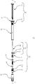
도 1은 본 발명에 따른 안전 주사기의 제 1 실시형태의 등각도이고;
도 2는 도 1에 도시된 실시형태의 종축선에 따른 분해도이고;
도 3a는 본 발명의 하나의 실시형태에 따른 배럴 어댑터의 확대 측면도를 도시하고;
도 3b는 도 3a의 배럴 어댑터의 측면 투시도를 도시하고;
도 3c는 배럴 어댑터의 다른 부품으로부터 바늘 조립체를 분리한 도 3a의 배럴 어댑터의 부분 분해 측면도를 도시하고;
도 3d는 도 3a의 배럴 어댑터의 완전 분해도를 도시하고;
도 4는 본 발명의 하나의 실시형태에 따른 로킹 메커니즘의 등각도를 도시하고;
도 5는 본 발명의 하나의 실시형태에 따른 임의선택적인 O링을 구비하는 배럴 팁의 등각도를 도시하고;
도 6은 본 발명의 실시형태에 따른 바늘 시일 및 바늘 허브를 도시하고;
도 7은 본 발명의 실시형태에 따른 임의선택적 바늘 블록 클립을 도시하고;
도 8a 내지 도 8d는주사기가 바늘 주입, 약물 투여량 전달, 후퇴 작동, 및 바늘 후퇴의 단계들을 통해 진행할 때의 본 발명의 실시형태에 따른 배럴 어댑터를 포함하는 주사기의 측면도를 도시하고;
도 9a 내지 도 9d는 유사하게 주사기가 바늘 주입, 약물 투여량 전달, 후퇴 작동, 및 바늘 후퇴의 단계들을 통해 진행할 때의 도 8a 내지 도 8d에 도시된 실시형태의 확대 부분 단면도를 도시한다.1 is an isometric view of a first embodiment of a safety syringe according to the present invention;
Figure 2 is an exploded view along the vertical axis of the embodiment shown in Figure 1;
Figure 3a shows an enlarged side view of a barrel adapter according to one embodiment of the present invention;
Figure 3b shows a side perspective view of the barrel adapter of Figure 3a;
Figure 3c shows a partially exploded side view of the barrel adapter of Figure 3a, which separates the needle assembly from other parts of the barrel adapter;
Figure 3d shows a complete exploded view of the barrel adapter of Figure 3a;
4 shows an isometric view of a locking mechanism according to one embodiment of the present invention;
Figure 5 shows an isometric view of a barrel tip with an optional O-ring according to one embodiment of the invention;
Figure 6 shows a needle seal and needle hub according to an embodiment of the invention;
Figure 7 illustrates an optional optional needle block clip in accordance with an embodiment of the present invention;
Figures 8A-8D show side views of a syringe including a barrel adapter according to an embodiment of the present invention as the syringe proceeds through steps of needle injection, drug dose delivery, retraction operation, and needle retraction;
Figures 9A-9D similarly show enlarged partial cross-sectional views of the embodiment shown in Figures 8A-8D as the syringe proceeds through steps of needle injection, drug dose delivery, retraction operation, and needle retraction.
본 발명의 실시형태는 복잡한 제조 공정 또는 의약품 회사 또는 계약된 약물 충전 회사를 위한 조작 상의 변화를 필요로 함이 없이 향상된 사용자 안전성을 위해 신뢰할 수 있는 바늘 후퇴를 제공한다. 본 발명의 실시형태는 더 적은 수의 부품을 포함하는 비교적 단순화된 바늘 조립체를 제공하는 것으로서, 이것에 의해 사용자 친화적이고 안전한 후퇴가능한 주사기를 제공함과 동시에 제조 비용을 최소로 유지하고 및/또는 후퇴가능한 주사기의 매스 분배를 촉진한다. 특히 본 발명의 새로운 배럴 어댑터는, 바람직하게, 배럴에 일체형 바늘 조립체 및 후퇴 메커니즘을 제공하는 직선상-배럴, 플라스틱 배럴과 같은 다양한 구성 및 재료의 일차적인 약물 배럴에 적합화될 수 있다. 이와 같은 실시형태는 사전 충전된 약물 주사기 또는 사용 시 충전되는 주입 가능한 약물 주사기를 위해 사용될 수 있다. 그러므로, 본 발명의 적합성 후퇴 메커니즘은 직선상-유리 배럴과 같은 표준 배럴에 고정 상태로 부착되거나, 첨부되거나, 장착되거나, 아니면 결합될 수 있다. 그러나, 하나의 바람직한 실시형태에서, 배럴 어댑터는 다수의 상이한 방식으로 배열과 결합되도록 구성될 수 있고, 배럴 어댑터는 적어도 하나의 근위 연결 부분이 배럴의 원위 부분의 내경에 장착되도록, 그리고 배럴의 원위 부분의 내경 내에 위치하도록 형성되는 방식으로 구성된다. 그러므로, 배럴 어댑터는 어댑터의 적어도 하나의 근위 부분을 배럴의 원위 단부에 삽입 및 부착시키거나, 첨부시키거나, 장착시키거나, 또는 결합시킴으로써 표준 직선상-배럴 약물 챔버에 연결될 수 있다. 그러므로 본 발명의 새로운 배럴 어댑터 설계는 이것에 바늘 조립체를 장착하기 위한 특정의 배럴 형상 또는 구성을 가질 필요성을 제거한다. 이것은 제조 비용, 특히 구체적으로 가공된 유리 배럴의 제조와 관련된 제조 비용을 실질적으로 감소시킬 수 있다. 본 발명의 새로운 배럴 어댑터는, 예를 들면, 직선상 유리 배럴에 장착될 수 있으므로 더욱 복잡한 배럴 형상의 제조와 관련되는 제조 공정 및 제조 비용을 간소화할 수 있다. Embodiments of the present invention provide reliable needle retraction for improved user safety without requiring complex manufacturing processes or operational changes for drug companies or contracted drug filling companies. Embodiments of the present invention provide a relatively simplified needle assembly that includes fewer components, thereby providing a user-friendly and secure retractable syringe while at the same time keeping the manufacturing cost to a minimum and / Thereby facilitating the mass distribution of the syringe. In particular, the novel barrel adapter of the present invention can preferably be adapted to a primary drug barrel of various configurations and materials, such as a rectilinear-barrel, plastic barrel, which provides an integral needle assembly and retraction mechanism in the barrel. Such an embodiment may be used for pre-filled drug syringes or injectable drug syringes that are filled in use. Therefore, the conformity retraction mechanism of the present invention can be fixedly attached, attached, mounted, or otherwise coupled to a standard barrel, such as a straight-on glass barrel. However, in one preferred embodiment, the barrel adapter can be configured to be associated with the arrangement in a number of different ways, such that the barrel adapter is configured such that at least one proximal connecting portion is mounted to the inside diameter of the distal portion of the barrel, And is formed so as to be positioned within the inner diameter of the portion. Thus, the barrel adapter can be connected to a standard rectilinear-barrel drug chamber by inserting, attaching, attaching, or engaging at least one proximal portion of the adapter to the distal end of the barrel. The novel barrel adapter design of the present invention thus eliminates the need to have a specific barrel shape or configuration for mounting the needle assembly thereto. This can substantially reduce manufacturing costs, particularly the manufacturing costs associated with the manufacture of specifically processed glass barrels. The new barrel adapter of the present invention can be mounted on, for example, a straight-line glass barrel, thus simplifying the manufacturing process and manufacturing costs associated with the manufacture of more complex barrel shapes.
본 발명의 배럴 어댑터는 사용시에 선택할 수 있거나, 또는 제조 시에 배럴에 사전 부착될 수 있다. 선택가능한 옵션에서, 본 발명의 설계 및 구성에 의해 사용자는 특정의 설계 또는 치수의 바늘 및/또는 바늘 조립체를 선택할 수 있고, 그리고 약물 전달을 위한 주사기 배럴에 그것을 적합화시킬 수 있다. 예를 들면, 배럴 어댑터 및 바늘 조립체는 다수의 상이한 바늘 길이 또는 두께를 제공하도록 구성될 수 있다. 그러면 사용자는 자신이 원하는 바늘 치수를 갖는 배럴 어댑터를 선택할 수 있고, 이것을 약물을 전달하기 위한 주사기에 적합화시킬 수 있다. 도 1 및 도 2에 도시된 실시형태에서, 배럴 어댑터는 배럴에 직접 장착된다. 이러한 적합식 특징을 제공하기 위해 하나 이상의 추가의 부품이 사용될 수 있다. 예를 들면, 배럴에 배럴 어댑터의 배럴 팁을 연결하기 위해 하나 이상의 연결 부품이 사용될 수 있다. 이와 같은 실시형태에서, 하나의 연결 부품(예를 들면, 수용 부품)이 유리 배럴의 원위 단부 상에 고정 상태로 장착될 수 있다. 수용 부품은 일체형 후퇴 메커니즘을 구비하는 배럴 팁을 직접적으로 수용 및 맞물릴 수 있다. 대안적으로, 배럴 어댑터는 수용 부품과의 맞물림을 위해 사용되는 추가의 연결 부품(예를 들면, 결합 부품)을 포함할 수 있다. 본 기술분야의 당업자에게 공지된 탄성중합체 시일과 같은 다른 선택적 부품이 필요할 수 있고, 그리고 배럴 어댑터와 배럴 사이의 연결을 촉진시키기 위해 상기 디바이스 내에 결합될 수 있다. 바늘 치수와 무관하게 본질적으로 동일 부품을 포함하는 배럴 어댑터는 배럴 내로의 바늘의 완전한 후퇴를 촉진시키도록 특별 주문 생산될 수 있다. 본 기술분야의 당업자가 쉽게 이해할 수 있는 바와 같이, 예를 들면, 더 긴 바늘의 후퇴를 촉진시키도록 더 긴 편향 부재(예를 들면, 더 긴 스프링)가 반드시 선택될 수 있거나 개조될 수 있다. The barrel adapter of the present invention can be selected at the time of use or pre-attached to the barrel at the time of manufacture. In a selectable option, the design and construction of the present invention allows the user to select a needle and / or needle assembly of a particular design or dimension and adapt it to the syringe barrel for drug delivery. For example, the barrel adapter and needle assembly can be configured to provide a number of different needle lengths or thicknesses. The user can then select the barrel adapter with the desired needle size and adapt it to the syringe to deliver the drug. In the embodiment shown in Figures 1 and 2, the barrel adapter is mounted directly on the barrel. One or more additional components may be used to provide such a conforming feature. For example, one or more connecting parts may be used to connect the barrel tip of the barrel adapter to the barrel. In such an embodiment, one connecting part (e.g., a receiving part) can be fixedly mounted on the distal end of the glass barrel. The receiving component can directly receive and engage the barrel tip with an integral retraction mechanism. Alternatively, the barrel adapter may include additional connecting parts (e. G., Mating parts) used for engagement with the receiving part. Other optional components, such as an elastomeric seal known to those skilled in the art, may be required and may be coupled within the device to facilitate connection between the barrel adapter and the barrel. A barrel adapter, essentially comprising the same part, irrespective of the needle dimensions, can be customized to facilitate the complete retraction of the needle into the barrel. As can be readily appreciated by those skilled in the art, for example, a longer biasing member (e.g., a longer spring) may be selected or modified to facilitate retraction of a longer needle.
본 발명의 실시형태는 의약품 용도를 위해 쉽게 채용할 수 있는 재료 및 부품을 사용할 수 있는 구성을 제공하고, 이들 중 다수는 시판 부품 또는 표준 부품으로서 생각되고 있다. 이것은 전체 제조 비용을 감소시키고, 조립 공정을 능률화하고, 그리고 비표준 재료 및 부품의 사용과 종종 관련되는 불필요한 규제 사항을 방지한다. 추가적으로, 본 발명은 바늘 후퇴 메커니즘을 갖지 않는 종래의 주사기와 시각적으로 유사하고, 의사 및 자신이 투여하는 환자와 같은 최종 사용자를 위한 인체공학적이고, 그리고 매우 바람직한 집합적 안정성 기구를 제공하는 부품 및 디바이스를 제공한다. 따라서, 이들 실시형태는 약물 충전 공정에 쉽게 통합되는 새롭고 비용 효율적인 부품 및 디바이스를 제공한다. Embodiments of the present invention provide a configuration in which materials and components that can be easily adopted for pharmaceutical applications can be used, and many of them are considered as commercial parts or standard parts. This reduces overall manufacturing costs, streamlines the assembly process, and avoids unnecessary restrictions often associated with the use of non-standard materials and components. Additionally, the present invention provides a device and a device that are visually similar to conventional syringes that do not have a needle retraction mechanism and that provide ergonomic and highly desirable collective stability mechanisms for end users, Lt; / RTI > Thus, these embodiments provide new and cost effective components and devices that are easily integrated into the drug filling process.
더욱이, 본 발명의 실시형태는 유체 용량의 효율적인 전달을 제공하고, 그 결과 의약품 약물의 손실을 최소화한다. 유사하게 본 발명의 실시형태는 비활용 공간, 예를 들면, 주사기 배럴 내의 중간 공극을 최소화시키고, 이것은 조립 또는 충전 공정 중에 원하지 않는 기포의 포획을 감소시키거나 제거한다. 본 발명의 이러한 양태는 극히 바람직한 기능적 및 심미적 특성을 제공할 수 있고, 그리고 다양한 상이한 구성을 제공하기 위해 개조될 수 있다. Moreover, embodiments of the present invention provide efficient delivery of fluid capacity and, consequently, minimal loss of drug medication. Similarly, embodiments of the present invention minimize mid-voids in the unoccupied space, e.g., the syringe barrel, which reduces or eliminates the trapping of unwanted bubbles during assembly or filling processes. This aspect of the invention may provide highly desirable functional and aesthetic characteristics and may be modified to provide a variety of different configurations.
예를 들면, 본 발명의 실시형태는 확개형(flared) 바늘, 즉 배럴의 약물 챔버 내의 비활용 공간을 감소시키기 위해 그 근위 단부에서 확개된 바늘을 사용할 수 있다. 바늘의 확개는 바늘 시일의 원위 면(distal face)과 라인-투-라인(line-to-line) 끼워맞춤 또는 그 표면과 억지끼워맞춤되도록 구성될 수 있다. 이러한 구성으로 인해, 바늘과 바늘 시일 사이에 비활용 공간이 최소로 형성되거나 전혀 형성되지 않고, 이것은 약물 충전 및 투여량 전달의 정확도를 향상시킨다. 본 발명의 이러한 구성은 또한 제조 공정을 크게 단순화시킨다. 바늘 시일은 바늘을 수용하기 위해 사전 천공될 수 있거나, 또는 조립 시에 바늘에 의해 천공될 수 있다. 이러한 구성의 양자 모두에서, 바늘을 바늘 시일에 결합시키기 위한, 또는 배럴 어댑터, 후퇴 메커니즘, 또는 안전 주사기의 임의의 특징을 유효하게 하기 위한 추가의 부품이 불필요하다. For example, an embodiment of the present invention may use a flared needle, i.e., a needle that is widened at its proximal end to reduce unused space in the drug chamber of the barrel. The widening of the needle can be configured to force-fit with or a line-to-line fit with the distal face of the needle seal. With this arrangement, there is minimal or no formation of unutilized space between the needle and the needle seal, which improves the accuracy of drug filling and dose delivery. This configuration of the present invention also greatly simplifies the manufacturing process. The needle seal may be pre-drilled to receive the needle, or it may be perforated by the needle during assembly. In both of these configurations, no additional parts are required to couple the needle to the needle seal, or to enable any feature of the barrel adapter, retraction mechanism, or safety syringe.
본 발명의 주사기는 바늘 찔림 부상에서 공통적인 바와 같은 바늘에 우발적으로 노출되는 것을 방지하므로 통합된 안전성으로 약물 전달을 가능하게 한다. 위에서 설명되고, 도면에 상세히 도시된 바와 같이, 사용자는 바늘 주입, 약물 투여량 전달, 후퇴 작동, 및 바늘 후퇴를 포함하는 약물 전달의 단계를 수행하기 위해 본 발명의 안전 주사기를 사용할 수 있다. 주목할 만하게도, 본 발명의 배럴 어댑터의 부품은 바늘 주입 및 약물 투여량 전달의 단계를 통해 실질적으로 소정의 위치에 유지된다. 이러한 새로운 특징에 의해, 최종 투여량의 기준점이 일정하므로, 배럴에 눈금을 붙이는 것이, 즉 용적을 표시하는 것이 가능해진다. 약물의 일부의 양이 여전히 배럴의 약물 챔버 내에 잔류할 수 있는, 바늘 주입 및 투여량 전달의 단계들을 통한 바늘 시일의 실질적으로 안정하고 일정한 위치로 인해, "영의 용적(zero volume)", 즉 챔버 내에 잔류하는 약물이 존재하지 않는 지점의 식별이 가능해진다. 이 지점으로부터 배럴의 축선 방향의 길이를 따라 근위 방향으로 이동하는 경우, 약물 체적은 배럴의 직경에 기초하여 계산될 수 있고, 그리고 배럴의 길이를 따라 표시될 수 있다. 원통형 배럴의 체적을 측정하고 눈금을 표시하기 위한 본 기술분야의 당업자에게 공지된 수종의 방법론이 존재한다. 따라서, 본 발명의 어댑터 및 주사기의 새로운 설계로 인해, 눈금을 표시한 주사기 배럴의 사용이 가능해진다. 이것은 의료 전문가 및 환자를 포함하는 주사기 사용자를 위해 바람직한 특징이다. The syringe of the present invention prevents accidental exposure to the needle as is common in needle pricking, thus enabling drug delivery with integrated safety. As described above and shown in detail in the drawings, a user can use the safety syringe of the present invention to perform steps of drug delivery including needle injection, drug dose delivery, retraction operation, and needle retraction. Notably, the components of the barrel adapter of the present invention are maintained in a substantially predetermined position through the steps of needle injection and drug dose delivery. With this new feature, since the reference point of the final dose is constant, it becomes possible to attach a scale to the barrel, that is, to display the volume. Due to the substantially stable and constant position of the needle seal through the steps of needle injection and dose delivery, where the amount of a portion of the drug may still remain in the drug chamber of the barrel, i.e., the " zero volume " It becomes possible to identify the point where the drug remaining in the chamber is not present. When moving from this point along the axial length of the barrel in the proximal direction, the drug volume can be calculated based on the diameter of the barrel and can be displayed along the length of the barrel. There are several methodologies known to those skilled in the art for measuring and calibrating the volume of a cylindrical barrel. Thus, due to the novel design of the adapter and syringe of the present invention, the use of a scaled barrel of syringe becomes possible. This is a desirable feature for syringe users, including medical professionals and patients.
주사기 재사용 및/또는 바늘 찔림 부상을 방지하거나 적어도 최소화하기 위해 하나 이상의 로킹 시스템을 결합함으로써, 본 발명의 실시형태는 제조에 대해 비용 효율성이 있고, 의사 및 자신이 투여하는 환자에 의한 사용상의 편리성이 있는 극히 바람직한 제품을 제공한다. 이와 같은 로킹 시스템은, 예를 들면, 바늘 후퇴 메커니즘 및/또는 후퇴된 바늘이 주사기의 단부로부터 다시 연장하는 것을 차단하는 장치를 포함할 수 있다. 본 발명의 배럴 어댑터 및 주사기의 새로운 기구 및 기능성은 사용자에게 다수의 안전성 이점을 제공한다. 예를 들면, 로킹 메커니즘은 약물 투여량이 완전히 전달되었다는 것, 후퇴 메커니즘이 작동되었다는 것, 바늘이 후퇴되었다는 것, 주사기가 폐기를 위해 안전하다는 것을 사용자에게 시각적, 청각적 및/또는 촉각적 피드백을 제공하도록 구성될 수 있다. 본 발명의 부품은 또한 사용의 말기에 부품 및 주사기 전체의 파괴가 증가되도록 구성된다. 이와 같은 일체형 안전성 및 파괴는 주사기의 재사용 가능성을 방지하고, 디바이스의 안전성 프로파일을 증가시킨다. 예를 들면, 임의선택적 바늘 블록은 바늘 후퇴 후 배럴 팁으로부터 근위 방향으로의 바늘의 병진운동을 방지하도록 구성될 수 있다. 이러한 구성에서 플런저 로드의 누름 및 바늘의 근위 방향으로의 병진 운동은 사용자에 의해 힘이 가해질 때 배럴 내에서 바늘이 굴곡되는 것을 초래한다. 본 발명에 의해 가능한 다른 안전성 특징은 바늘의 후퇴 속도를 제어하는 능력이다. 제어된 바늘 후퇴는 약물 투여량이 전달된 후 환자에 대한 부상을 방지한다. 이것은 후퇴 활성화 시 편향 부재의 팽창 속도를 제한하는 하나 이상의 마찰 부재와 같은 활성 부품에 의해, 또는 더 느리게 팽창하는 편향 부재의 선택과 같은 수동적 부품에 의해 촉진될 수 있다. 도 1 및 도 2에 도시된 실시형태에서, 후퇴는 플런저 로드 및 플런저 시일에 의해 제어된다. 최후의 투여량에서, 바늘 후퇴의 활성화 시, 사용자는 플런저 로드의 근위 단부에 여전히 접촉한 상태로 힘을 가하고 있다. 편향 부재의 팽창이 유발됨에 따라, 이것은 바늘 및/또는 바늘 조립체를 후퇴시키도록 근위 방향으로 축방향 힘을 부여한다. 이러한 작용은 투여의 말기에 바늘 시일과 접촉해 있는 플런저 시일과 플런저 로드에 힘을 전달한다. 바늘 시일 및 플런저 시일에 의해 유발되는 배럴의 내부에 대한 마찰은 바늘 조립체의 후퇴 속도를 제한한다. 사용자가 플런저 로드 상에 가하는 힘을 감소시킴에 따라, 사용자는 바늘의 후퇴 속도를 제어할 수도 있다. 이러한 제어된 후퇴는 이것이 안정성을 향상시키고 환자가 느끼는 고통을 감소시키므로 주사기 사용자가 매우 원하는 것이다. By incorporating one or more locking systems to prevent, or at least minimize, syringe reuse and / or needle pricking injuries, embodiments of the present invention are cost effective for manufacture and provide ease of use by the physician and the patient To provide an extremely desirable product. Such a locking system may include, for example, a needle retraction mechanism and / or a device for blocking retracted needles from extending again from the end of the syringe. The new mechanism and functionality of the barrel adapter and syringe of the present invention provide the user with a number of safety benefits. For example, the locking mechanism may provide visual, auditory and / or tactile feedback to the user that the drug dose is fully delivered, that the retraction mechanism has been activated, that the needle has been retracted, and that the syringe is safe for disposal . The components of the present invention are also configured to increase the failure of the part and the syringe in the end of use. Such integral safety and destruction prevents the reusability of the syringe and increases the safety profile of the device. For example, the optional optional needle block may be configured to prevent translational movement of the needle from the barrel tip in the proximal direction after needle retraction. In this configuration, the pushing of the plunger rod and the translational movement of the needle in the proximal direction cause the needle to bend in the barrel when the force is applied by the user. Another safety feature possible with the present invention is the ability to control the retraction rate of the needle. Controlled retraction of the needle prevents injury to the patient after delivery of the drug dose. This can be facilitated by active components such as one or more friction members that limit the rate of expansion of the biasing member upon retraction activation, or by passive components such as the selection of a biasing member that expands more slowly. In the embodiment shown in Figures 1 and 2, retraction is controlled by the plunger rod and the plunger seal. At the last dose, upon activation of the needle retraction, the user is applying a force still in contact with the proximal end of the plunger rod. As the deflection of the biasing member is induced, it imparts an axial force in the proximal direction to retract the needle and / or needle assembly. This action transfers the force to the plunger seal and the plunger rod in contact with the needle seal at the end of the administration. Friction with respect to the interior of the barrel caused by the needle seal and plunger seal limits the retraction rate of the needle assembly. As the user reduces the force applied on the plunger rod, the user may control the retraction speed of the needle. This controlled retraction is what a syringe user would like very much because it improves stability and reduces patient pain.
첨부한 도면에 대해 본 발명의 실시형태를 더 상세히 설명한다. 이것은 단지 비제한적 실시형태라는 것과 본 발명의 관찰 내에서 그리고 본 개시의 폭 및 범위 내에서 다른 유사한 실시형태가 존재할 수 있다는 것을 이해해야 한다. BRIEF DESCRIPTION OF THE DRAWINGS Fig. It should be understood that this is merely a non-limiting embodiment and that there may be other similar embodiments within the scope of the present invention and within the breadth and scope of the disclosure.
본 발명의 주사기, 배럴, 배럴 어댑터, 또는 부품의 임의의 상대적 위치를 설명하기 위해 본 명세서에서 사용될 때, 용어 "축선 방향" 또는 "축선 방향으로"는 일반적으로 종축선 "A"를 기준으로 하고, 비록 절대적으로 대칭인 것은 아니지만 이것을 중심으로 주사기 또는 배럴이 형성되는 것이 바람직하다. 용어 "반경 방향"는 일반적으로 축선(A)에 수직한 방향을 말한다. 일반적으로 용어 "근위", "후방", "후방으로" "후측" 또는 "후측으로"는 배럴 팁(32)으로부터 멀어지는 축선 방향을 말한다. 일반적으로 용어 "원위", "전방", "전방으로", "눌려진" 또는 "전방에"는 배럴 팁(32)을 향하는 축선 방향을 말한다. 본 명세서에서 용어 "스프링"은 압축될 수 있고 그리고 소정의 방향으로 팽창될 수 있는 실질적으로 나선상으로 권선된 코일과 같은 편향 부재를 제안하기 위해 사용되는 것으로 이해해야 한다. 본 명세서에 상세하게 기재된 실시형태에서 설명되고 사용되는 장치와 같은 스프링 요소가 사용될 수 있으나, 다른 유형의 편향 부재가 본 발명의 폭 및 범위 내에 유지되는 상태에서 동일한 목적을 위해 쉽게 사용될 수 있다는 것은 본 발명의 의도 내에 속한다. 예를 들면, 압축 스프링, 비틀림 스프링, 일정력(constant force) 스프링, 인장 스프링, 판 스프링과 같은 스프링, 또는 상이한 유형의 스프링의 조합이 통상 전문가가 이해할 수 있는 바와 같이 본 발명의 범위 내에서 사용될 수 있다. 추가적으로 또는 대안적으로, 스프링 이외의 편향 부재가 또한 유사한 목적을 위해 사용될 수 있다. 편향 부재의 비제한적 실시예는 스프링, 탄성 디바이스 또는 방출될 수 있는 에너지를 저장하기 위한 기타 디바이스를 포함한다. 그러나, 적어도 하나의 실시형태에서, 편향 부재는 압축 스프링과 같은 스프링이 바람직하다. As used herein to describe any relative position of a syringe, barrel, barrel adapter, or part of the present invention, the terms "axial" or "axial" refer generally to the longitudinal axis "A " , Although it is not absolutely symmetric, it is desirable that a syringe or barrel be formed around it. The term "radial direction" generally refers to a direction perpendicular to the axis A. Generally, the terms "proximal", "rearward", "rearward", "rearward" or "rearward" refer to the axial direction away from the
본 명세서에서 사용될 때, 용어 "유리(glass)"는 통상적으로 유리를 필요로 하는 의약품 등급의 용도로 사용하기에 적합한 기타 유사한 비반응성 재료를 포함하는 것으로 이해해야 한다. 용어 "플라스틱"은 열가소성 및 열경화성 폴리머의 양자 모두를 포함할 수 있다. 열가소성 폴리머는 열에 의해 그 원래 상태로 재연화될 수 있고, 열경화성 폴리머는 그 원래 상태로 재연화될 수 없다. 본 명세서에서 사용될 때, 용어 "플라스틱"은, 예를 들면, 폴리에틸렌 및 폴리프로필렌과 같은 성형 가능한 열가소성 고중합체 또는 아크릴 수지로서, 전형적으로 경화제, 충전재, 강화제, 착색제, 및/또는 가소제 등과 같은 다른 성분을 또한 포함하고, 그리고 열 및 압력 하에서 성형되거나 주조될 수 있는 것을 주로 말한다. 본 명세서에서 사용될 때, 용어 "플라스틱"은 플라스틱과 상호 작용할 수 있거나 또는 플라스틱으로부터 액체 내에 혼입할 수 있는 치환기에 의해 열화될 수 있는 치료적 액체와 직접 접촉하는 용도에서 사용을 위해 승인된 유리 또는 고무상 탄성중합체를 포함하지 않는다. 본 명세서에서 사용될 때, 용어 "탄성중합체" 또는 "탄성중합체 재료"는 플라스틱보다 용이하게 변형될 수 있으나, 의약품 등급 유체와 함께 사용하도록 승인되고 침출이나 기체 이동을 일으키기 쉽지 않은 가교결합된 열경화성 고무상 폴리머를 주로 말한다. 본 명세서에서 사용될 때, 용어 "유체"는 주로 액체를 말하지만, 또한 액체 내에 분산된 고체의 현탁액, 및 주사기의 유체 함유 부분 내의 액체 내에 용해되거나 이 액체와 함께 존재하는 기체를 포함할 수도 있다. As used herein, the term "glass" should be understood to include other similar non-reactive materials suitable for use in pharmaceutical grade applications that typically require glass. The term "plastic" may include both thermoplastic and thermosetting polymers. The thermoplastic polymer can be refolded to its original state by heat, and the thermosetting polymer can not be refurbished to its original state. As used herein, the term "plastic" is a moldable thermoplastic high polymer or acrylic resin such as, for example, polyethylene and polypropylene, and typically includes other components such as hardener, filler, reinforcing agent, colorant, and / And can be molded or cast under heat and pressure. As used herein, the term "plastic" refers to a glass or a glove approved for use in applications that can interact with the plastics or in direct contact with therapeutic fluids that can be degraded by substituents that can enter the liquid from the plastics. It does not contain a free elastomer. As used herein, the term "elastomeric material" or "elastomeric material" refers to a cross-linked thermosetting rubbery material that is more readily deformable than plastics, but approved for use with pharmaceutical grade fluids, Polymer mainly refers to. As used herein, the term "fluid" refers primarily to a liquid, but may also include a suspension of solids dispersed in a liquid, and a gas dissolved or present with the liquid in the fluid containing portion of the syringe.
추가적으로, 본 발명의 배럴 어댑터는 치료적 유체 또는 약물과 실질적으로 비반응성이고 의약품 등급의 용도에서 사용하기에 적절한 재료를 사용한다. 새로운 배럴 어댑터는 특정 플라스틱과 같은 분해성 재료와 치료적 유체 또는 약물 사이의 접촉 또는 상호작용의 가능성을 최소화하거나 제거하도록 구성된다. 적합성 바늘 파지 및 후퇴 메커니즘을 갖는 배럴 어댑터는 또한 일차적인 약물 챔버로부터 환자로의 바늘을 통한 유체 경로를 제공하고, 이 경로에는 분해성 재료가 실질적으로 존재하지 않는다. 이와 같은 새로운 어댑터 구성은, 본 발명의 새로운 안전 주사기를 제공하기 위해 배럴 내에 결합되었을 때, 약물 및 약물 전달 디바이스에 향상된 안전성 및 보관 수명 파라미터를 제공한다. 이러한 특성은 일반적으로 모든 의약품 치료에 대해 매우 바람직한 것으로 생각되지만, 아마도 생물학 및 기타 복잡한 치료에서 사용하기 위한 주사기에서 특히 가치를 가질 수 있다. 하나의 실시형태에서, 약물이 약물 챔버로부터 환자에게 이동할 때 플라스틱과 전혀 접촉하지 않고, 약물 유체 경로가 오로지 유리, 탄성중합체, 및 금속만을 포함하도록(그리고 약물이 오로지 유리, 탄성중합체, 및 금속에만 접촉하도록), 예를 들면, 금속 바늘은, 바늘의 근위 단부에서는 탄성중합체 바늘 시일에 의해 그리고 바늘 시일에 대해 원위에 위치하는 바늘의 부분에서는 플라스틱 배럴 팁의 개구에 의해, 유리 배럴 내에 파지된다. 다른 실시형태에서, 약물 유체 경로용으로 다른 재료의 조합 또는 더 적은 수의 재료가 사용될 수 있다. In addition, the barrel adapter of the present invention employs materials that are substantially non-reactive with the therapeutic fluid or drug and suitable for use in pharmaceutical grade applications. The new barrel adapter is configured to minimize or eliminate the possibility of contact or interaction between the degradable material, such as certain plastics, and the therapeutic fluid or drug. The barrel adapter with compliance needle retraction and retraction mechanism also provides a fluid path through the needle from the primary drug chamber to the patient, which path is substantially free of degradable material. This new adapter configuration provides improved safety and shelf life parameters for drug and drug delivery devices when coupled into a barrel to provide a novel safety syringe of the present invention. These properties are generally considered highly desirable for all drug treatments, but may be of particular value in syringes for use in biology and other complex treatments. In one embodiment, when the drug is not in contact with the plastic at all as it moves from the drug chamber to the patient and the drug fluid pathway is comprised solely of glass, elastomer, and metal (and the drug is solely contained in glass, elastomer, For example, the metal needle is held in the glass barrel by the elastomeric needle seal at the proximal end of the needle and by the opening of the plastic barrel tip at the part of the needle located on the circle against the needle seal. In other embodiments, a combination of different materials or fewer materials may be used for the drug fluid path.
하나 이상의 본 발명의 실시형태는 특정의 표준 부품을 추가로 포함할 수 있다. 예를 들면, 본 발명의 배럴 어댑터 구성 및 주사기 디바이스는 하나 이상의 O링을 포함할 수 있다. 적어도 하나의 실시형태에서, 배럴 내에서 배럴 팁을 밀봉하기 위해 및/또는 배럴의 약물 챔버 내의 무균 환경 및 용기의 완전성을 보장하기 위해 하나 이상의 O링이 사용된다. One or more embodiments of the present invention may further include certain standard components. For example, the barrel adapter arrangement and syringe device of the present invention may include one or more O-rings. In at least one embodiment, one or more O-rings are used to seal the barrel tip within the barrel and / or to ensure integrity of the aseptic environment and vessel within the drug chamber of the barrel.
추가적으로 또는 대안적으로, 배럴 어댑터는 후퇴율의 제어를 촉진하기 위한 하나 이상의 제어 부재를 포함할 수 있다. 유사하게, 배럴 어댑터는 클립, 플랩(flap), 플랜지, 등과 같은 하나 이상의 바늘 블록을 포함할 수 있고, 이것은 후퇴 메커니즘이 개시된 후 또는 완료된 후에 바늘이 배럴 팁의 개구를 통해 배럴로부터 외부로 병진운동되거나 돌출하는 것을 방지하는 기능을 발휘한다. Additionally or alternatively, the barrel adapter may include one or more control members to facilitate control of the rate of retraction. Similarly, the barrel adapter may include one or more needle blocks, such as clips, flaps, flanges, etc., which allow the needle to be translated from the barrel through the opening of the barrel tip to the outside after the retraction mechanism is initiated or completed Or protruding from the surface.
더욱이, 안전 주사기는 심미성, 사용상의 편리성, 또는 다른 목적을 위한 하나 이상의 부품을 포함할 수 있다. 예를 들면, 하나 이상의 본 발명의 실시형태는 핑거 플랜지를 포함할 수 있다. 핑거 플랜지는 배럴 또는 안전 주사기의 임의의 부분을 따라 사전 형성될 수 있거나, 또는 배럴 또는 안전 주사기에 연결되거나 부착되는 별개의 부품일 수 있다. 적어도 하나의 실시형태에서, 핑거 플랜지는 배럴의 근위 단부에 사전 형성된 부품이다. 핑거 플랜지는 이 플랜지 상에 사용자의 검지와 중지를 지지할 수 있도록 구성될 수 있고, 사용자가 약물의 주입을 위해 엄지 손가락으로 플런저를 누룰 때 지렛대 작용 인터페이스를 제공할 수 있다. 이와 같은 부품의 위치, 형상, 개수, 및 재료는, 당업자에 의해 쉽게 이해될 수 있는 바와 같이, 임의의 개수의 원하는 특징에 부합하도록 변화될 수 있다. Moreover, the safety syringe may include one or more components for aesthetics, ease of use, or other purposes. For example, one or more embodiments of the present invention may include a finger flange. The finger flange may be preformed along any part of the barrel or safety syringe, or it may be a separate part connected to or attached to the barrel or safety syringe. In at least one embodiment, the finger flange is a preformed part at the proximal end of the barrel. The finger flange can be configured to support the user's detection and pause on the flange and provide a leverage interface when the user is pressing the plunger with the thumb for injection of the drug. The location, shape, number, and material of such components may be varied to accommodate any number of desired features, as will be readily appreciated by those skilled in the art.
유사하게, 배럴 어댑터 및 안전 주사기의 부품을 본 명세서에서 별개의 부품으로서 설명하였으나, 이들 부품의 특정 그룹은 개별 부품의 기능을 수행할 수 있는 단일 부품을 형성하기 위해 조합될 수 있다는 것이 본 발명의 의도 내에 포함된다. 위에서 설명한 바와 같이, 예를 들면, 적어도 하나의 실시형태에서, 바늘 허브 및 바늘 시일은 이중 기능을 제공하는 하나의 통합된 부품일 수 있다. 추가적으로, 본 기술분야의 당업자가 이해할 수 있는 바와 같이, 안전 주사기의 부품은 개별 부품으로서 또는 단일의 부품으로서 제조될 수 있다. 위에서 설명한 바와 같이, 핑거 플랜지는 제조 공정 중에 배럴 자체의 일부로서 사전 형성되는 부품일 수 있다. 따라서, 적어도 하나의 실시형태에서, 핑거 플랜지는 배럴의 유리 핑거 플랜지 연장부일 수 있다. Similarly, although the components of the barrel adapter and safety syringe are described herein as separate components, it is contemplated that certain groups of these components may be combined to form a single component capable of performing the functions of the individual components. Are included within the intent. As described above, for example, in at least one embodiment, the needle hub and needle seal may be one integrated part that provides dual functionality. Additionally, as will be understood by those skilled in the art, the parts of the safety syringe may be manufactured as discrete parts or as a single part. As discussed above, the finger flange can be a preformed part as part of the barrel itself during the manufacturing process. Thus, in at least one embodiment, the finger flange can be a glass finger flange extension of the barrel.
더욱이, 본 명세서에서 배럴 어댑터의 부품이 별개의 부품으로서 설명되었으나, 이들은 다중 기능을 갖는 통합된 부품일 수 있다. 위에서 설명된 바와 같이, 편향 부재(예를 들면, 스프링)는 활성화된 상태에서 압축될 수 있고, 로킹 메커니즘은 배럴 팁 내에 설치되기 전이나 부품이 배럴 내에 장착되기 전에 맞물릴 수 있다. 부품 및 그 조립체의 구성은 조립 공정, 디바이스 파라미터 및 다른 원하는 특징에 기초하여 변화될 수 있다. Moreover, although the components of the barrel adapter are described herein as separate components, they may be integral parts having multiple functions. As described above, the biasing member (e.g., spring) can be compressed in the activated state, and the locking mechanism can be engaged before being installed in the barrel tip or before the part is mounted in the barrel. The configuration of the part and its assembly may be varied based on the assembly process, device parameters, and other desired characteristics.
도 1은 본 발명에 따른 안전 주사기(10)의 하나의 실시형태의 등각도를 도시한다. 도 2는 도 1에 도시된 안전 주사기(10) 및 그 부품의 분해도를 도시한다. 본 발명에 따르면, 배럴 어댑터(20)는 플런저 조립체(12)를 갖는 주사기 배럴(18)에의 부착을 위해 제공된다. 본 발명의 실시형태의 장점으로서, 배럴 어댑터(20)의 배럴 팁(32)은 임의의 적절한 방법에 의해 임의의 표준 배럴(18)과 결합하도록 구성될 수 있다. 배럴(18)은 플라스틱 배럴, 유리 배럴, 또는 의료용 디바이스에서 사용하도록 임의의 다른 공지된 재료로 제조되는 배럴일 수 있다. 배럴(18)은 테이퍼형, 비원통형, 또는 실질적으로 직선형일 수 있다. 제조의 목적을 위해 바람직한 하나의 실시형태에서, 배럴(18)은 직선상 배럴의 유리 실린더이다. 본 발명의 실시형태는 또한 안전 주사기를 위한 시장에서 상당한 다른 장점을 가능하게 할 수도 있다.1 shows an isometric view of one embodiment of a
예를 들면, 하나 이상의 실시형태는 표준 플런저 로드, 플런저 시일, 및 강성의 바늘 차폐체와 같은 표준 부품을 사용할 수 있고, 그 결과 특수 가공 또는 사출 성형된 부품의 필요성을 크게 감소시킬 수 있다. 예를 들면, 도 1 및 도 2는 전달 주사기(10)는, 다른 가능한 표준 부품 중에서도, 표준 플런저 로드(14), 플런저 시일(16), 및 강성의 바늘 차폐체(38)를 사용하는 실시형태를 도시한다. 플런저 시일(16)은, West Pharmaceutical Services, Inc.(Lionville, Pennsylvania)로부터 상표명 "FluroTec"에 의해 용이하게 구입할 수 있는 것과 같은, 예를 들면, 에틸렌 테트라플루오로에틸렌(ETFE) 코팅된 고무 스토퍼/시일일 수 있다. 유사하게 다른 부품도 본 발명의 실시형태의 큰 장점을 제공하는 표준 시판 부품일 수 있다. 본 발명의 실시형태의 이러한 장점은 유익한 제조 효율 및 작동 비용 절약을 제공한다. For example, one or more embodiments can use standard parts such as standard plunger rods, plunger seals, and rigid needle shields, which can greatly reduce the need for special machining or injection molded parts. For example, Figures 1 and 2 illustrate an embodiment using
배럴 어댑터(20)는 본 기술분야의 당업자가 이해할 수 있는 바와 같이 임의의 적절한 커플링 배열에 의해 주사기 배럴(18)에 장착될 수 있다. 예를 들면, 배럴 어댑터(20)는 배럴 어댑터(20) 및 주사기 배럴(18)의 부품과 별개이거나 배럴 어댑터(20) 및 주사기 배럴(18)과 일체인 커플링 구조물에 의해 주사기 배럴(18)에 결합될 수 있다. 더욱이, 배럴 어댑터(20)는 주사기 제조 공정 중에 또는 사용 직전에 주사기 배럴(18)에 결합될 수 있다. 단지 예시로서, 주사기 어댑터(20)는 주사기 제조 공정 중에 억지끼워맞춤, 접착제 등에 의해 주사기 배럴(18)에 결합될 수 있다. 대안적으로, 예를 들면, 주사기 배럴(18) 및 배럴 어댑터(20)는 맞물림 나사산 또는 루어(Luer) 로킹 장치를 포함할 수 있으므로 배럴 어댑터(20)는 사용 직전에 주사기 배럴(18)에 결합될 수 있다. The
배럴 어댑터(20)는 주사기 배럴(18)에 바늘(28)의 장착(도 2 참조)을 촉진한다. 배럴 어댑터(20)는 배럴 팁(32), 바늘 조립체(42), 및 바늘 후퇴 메커니즘(21)을 포함한다. 배럴 팁(32)은 주사기 배럴(18)에의 배럴 어댑터(20)의 부착에 관련하여 위에서 설명한 바와 같은 임의의 적절한 방법으로 주사기 배럴(18)에 결합될 수 있다. 배럴 팁(32)은 전형적으로 주사기 배럴(18)에 결합되었을 때 안전 주사기(10)의 원위 단부를 제시하고, 바늘(28)은 약제의 주입 중에 배럴 팁의 원위 단부를 통해 연장한다. 배럴 팁(32)은, 이하에서 설명하는 바와 같이, 바늘 후퇴 메커니즘(21)의 일부를 형성하는 구조물을 더 포함할 수 있다. The
바늘 조립체(42)는 일반적으로 바늘(28), 바늘 허브(24), 및 바늘 시일(26)을 포함할 수 있다. 바늘(28)의 일단부는 배럴(18)의 내부에 위치되도록, 그리고 바늘(28)의 타단부는 배럴 팁(32) 내의 개구를 통과하도록, 바늘(28)은 바늘 조립체(42)의 바늘 허브(24) 및 바늘 시일(26) 뿐만 아니라 로킹 메커니즘(22), 스프링(30) 및 배럴 팁(32)을 관통하도록 구성된다. 일부의 실시형태에서, 바늘 허브(24) 및 바늘 시일(26)은 하나의 부품일 수 있고, 한편 다른 실시형태에서 이들은 2 개 이상의 부품을 포함할 수 있다. 예를 들면, 하나의 실시형태에서, 바늘 허브(24) 및 바늘 시일(26)은 듀얼-샷(dual-shot) 플라스틱 바늘 허브(24) 및 탄성중합체 바늘 시일(26)과 같은 단일화된 유닛이다. The
바늘 조립체(42)가 환자에 대한 약물의 주입을 위한 최초 단계에 있는 상태에서, 바늘 시일(26) 및 바늘 허브(24)는 배럴(18) 내의 실질적으로 고정된 위치 내에 유지되도록 구성될 수 있다. 대안적으로, 바늘 시일(26) 및 바늘 허브(24)는, 예를 들면, 플런저 로드(14)가 눌려짐에 따라, 주입 위치로 이동하도록 구성될 수 있다. The
바늘(28)에 의한 부주의한 찔림이나 약제의 투여 후의 주사기(10)의 재사용을 방지하기 위해, 배럴 어댑터(20)는 바늘 후퇴 메커니즘(21)을 포함한다. 본 발명의 하나의 양태에 따르면, 바늘 후퇴 메커니즘(21)의 작동에 의해, 바늘(28)을 통한 약제의 전달 후에, 바늘 조립체(42) 중의 적어도 바늘(28)은 배럴 어댑터(20) 내로 후퇴된다. 바늘 후퇴 메커니즘(21)은 편향 부재(30) 및 작동 가능한 로킹 장치(31)를 포함하고, 작동 가능한 로킹 장치(31)는 바늘 조립체(42)의 바늘(28)이 배럴 어댑터(20) 내로 후퇴될 때까지 편향 부재(30)를 활성화된 위치에 유지한다. 로킹 장치(31)는 바늘이 후퇴되어야 할 때까지 편향 부재(30)를 활성화된 위치에 유지하는 임의의 적절한 설계를 가질 수 있으나, 도시된 실시형태에서, 로킹 장치(31)는 로킹 메커니즘(22) 및 로킹 형상부(32a)를 포함하고, 로킹 형상부(32a)는 활성화된 위치에 편향 부재(30)를 유지하는 표면의 상대 위치를 유지하도록 결합되고, 이것은 이하에서 더 상세히 설명한다. 로킹 장치(31)의 작동시, 편향 부재(30)는 배럴 어댑터(20) 내로 바늘(28)이 후퇴하도록 한다. The
로킹 장치(31)의 이와 같은 하나의 실시형태에서 편향 부재(30)는 압축 스프링이다. 스프링(30)의 단부는 로킹 메커니즘(22)의 표면(23) 및 배럴 팁(32) 내의 표면(25)에 인접하여 배치된다. 표면(23, 35)의 상대 위치는 주입 전에 압축된 그리고 활성화된 위치에 편향 부재(30)를 유지하거나, 또는 주입 후에 바늘(28)을 후퇴시키기 위해 비활성화된 위치로의 스프링(30)의 이동을 허용한다. 스프링(30)을 활성화된 위치에 유지하기 위해, 로킹 메커니즘(22) 및 배럴 팁(32)은 비활성화된 위치로 스프링(30)의 이동을 허용하도록 분리될 수 있는 맞물림 구조물을 포함한다. In one such embodiment of the
바늘 후퇴 메커니즘(21)은 임의의 적절한 트리거(trigger)에 의해 작동될 수 있다. 예를 들면, 도시된 실시형태에서, 바늘 후퇴 메커니즘(21)은 플런저 시일(16)을 바늘 조립체(42)와의 접촉 상태로 이동시킴으로써 작동된다. 이와 같은 구성에서, 바늘 허브(24)는 로킹 메커니즘(22) 상에 강제로 접촉 및/또는 가압될 수 있다. 이러한 접촉에 의해 로킹 메커니즘(22)은 분리될 수 있고, 이것에 의해 스프링(30)은 실질적으로 배럴(18)의 종축선을 따라 근위 방향으로 팽창할 수 있고, 이것에 의해 로킹 메커니즘(22), 및 바늘(28)을 포함하는 바늘 조립체(42)의 부품은 배럴(18) 내로 후퇴된다. The
바늘 후퇴 메커니즘(21)의 도시된 결합 구조에서, 로킹 메커니즘(22)은 배럴 팁(32)의 하나 이상의 대응하는 로킹 형상부(32a)와 맞물리게 되고, 그리고 연결된 상태를 유지하게 된다. 바늘 허브(24)의 접촉에 의해, 그리고 사용자가 플런저 조립체(12)에 가하는 힘을 통해 로킹 메커니즘(22)이 원위 방향으로 병진운동하게 됨에 따라, 로킹 메커니즘(22)은 배럴 팁(32)의 하나 이상의 대응하는 로킹 형상부(32a)로부터 맞물림 해제될 수 있고, 이것에 의해 스프링(30)은 팽창될 수 있고, 후퇴 메커니즘이 작동될 수 있다. 로킹 형상부(32a)로부터 로킹 메커니즘(22)의 맞물림 해제는 로킹 메커니즘(22)의 축선 방향의 병진운동에 의해 유발될 수 있다. 추가적으로 또는 대안적으로, 로킹 형상부(32a)로부터 로킹 메커니즘(22)의 맞물림 해제는 축선 방향의 병진운동 시의 회전과 같은 로킹 메커니즘(22)의 회전에 의해 유발될 수 있다. 상기 회전은, 독자적으로 또는 축선 방향의 병진운동과 연동하여, 로킹 메커니즘(22)이 로킹 형상부(32a)와의 맞물림으로부터 이탈할 수 있도록 한다. 적어도 하나의 실시형태에서, 이러한 회전은, 압축 시 축선을 중심으로 하는 일방향으로 로킹 메커니즘(22)을 회전시키는, 비틀림식으로 편향된 압축 스프링에 의해 유발될 수 있다. 다른 실시형태에서, 회전은, 로킹 형상부(32a)의 성형에 의해, 또는 이러한 이동을 촉진하고, 그리고 부품의 맞물림 및 맞물림 해제를 허용하는 로킹 형상부(32a)와 로킹 메커니즘(22) 사이의 인터페이스에 의해, 로킹 메커니즘(22)의 피치식 양태 프로파일(pitched aspect profile)과 같은 이러한 기능을 가능하게 하는 로킹 메커니즘(22) 자체의 구성에 의해 유발될 수 있다. In the illustrated mating structure of the
바늘 허브(24)는 바늘을 실질적으로 고정된 위치에 유지하도록 기능할 수 있고, 배럴 어댑터(20) 및 안전 주사기(10)는 일반적으로 약물 주입을 위해 구성되는 최초 단계에 있다. 추가적으로 또는 대안적으로, 로킹 메커니즘(22)은 약물 주입을 위한 이러한 최초 단계 중에 바늘(28)을 실질적으로 고정된 위치에 유지하도록 기능할 수 있다. 그러므로, 도 1 및 도 2에 도시된 안전 주사기(10)는 종래의 바늘 홀더 또는 바늘-오버-몰드(needle-over-mold)(도시되지 않음)를 필요로 하지 않는 새로운 배럴 어댑터의 하나의 실시형태를 포함한다. 본 기술분야의 당업자는 종래의 바늘 홀더 또는 바늘-오버-몰드는, 예를 들면, 약물 주입을 위해 배럴(18) 내에 바늘의 파지를 도와주기 위해, 그리고 대안적으로 또는 추가적으로 주입 후 바늘의 후퇴를 도와주기 위해, 바늘 상에 형성되는 재료를 포함할 수 있다는 것을 이해할 것이다. 이와 같은 부품의 제거는 분해성 재료와 약물의 상호작용의 가능성을 더 감소시킬 수 있고, 동시에 잠재적인 제조 상의 이점 및 조작상 비용 절약이 유발된다. The
로킹 메커니즘(22)의 맞물림 해제 및 후퇴 메커니즘의 활성화 시에, 스프링(30)은 팽창될 수 있고, 이것에 의해 바늘 조립체(42)는 실질적으로 배럴의 종축선을 따라 근위 방향으로 후퇴된다. 로킹 메커니즘(22)의 해제 및 근위 방향으로 편향된 편향 부재(30)의 팽창 시에, 본 발명의 일부의 실시형태에서, 전체 바늘 조립체(42)는 후퇴되고, 한편 다른 실시형태에서는 바늘(28)을 포함하는 그 특정 부품만이 후퇴된다. 유사하게, 본 발명의 일부의 실시형태에서, 로킹 메커니즘(22)은 바늘 조립체(42)와 함께 후퇴되고, 다른 실시형태에서, 로킹 메커니즘(22)은 실질적으로 고정 상태를 유지하지만 바늘 조립체(42) 또는 그 부품은 이동할 수 있다. 바늘(28)의 후퇴가 개시되거나 완료된 후, 바늘 블록(34)은 바늘(28)이 배럴 팁(32)으로부터 원위 방향으로 병진운동하는 것을 방지하도록 기능한다. 위에서 설명한 바와 같이, 안전 주사기의 조립 시에 O링(36)과 같은 다른 표준 부품이 사용될 수 있다. Upon activation of the disengaging and retracting mechanism of the
약물 또는 의약품 화합물은 바늘 시일(26)의 근위 방향으로 배럴(18) 내에 수용될 수 있다. 통상 전문가에 의해 인정되는 바와 같이, 약물은 용액, 분말, 현탁액 등, 또는 이들의 임의의 조합물일 수 있다. 바늘 허브(24) 및 바늘 시일(26)은 그 중심에서(예를 들면, 이들 부품 및 배럴의 실질적으로 종축선에서) 관통구로서의 역할을 하는 개구를 갖는다. 이 개구는 바늘(28)의 직경과 동등한 직경을 가질 수 있고, 따라서 바늘(28)은 초기의 주입 단계 중에 바늘 허브(24) 및/또는 바늘 시일(26) 내의 정위치에 유지되고, 그리고 후퇴 메커니즘의 활성화 시, 바늘 허브(24) 및/또는 바늘 시일(26)과 함께 또는 바늘 허브(24) 및/또는 바늘 시일(26)을 제외하고, 근위 방향의 축선 방향으로 병진운동이 허용된다. 대안적으로, 초기에 바늘 시일(26)은, 조립 시, 바늘 시일(26) 내에 바늘(28)을 위치시키기 전에 개구를 갖지 않을 수 있다. 이러한 구성에서, 바늘(28)은 조립 시에 바늘 시일(26)을 관통하도록 가압될 수 있고, 그리고 라인-투-라인 끼워맞춤 또는 억지끼워맞춤을 형성하고, 그 결과 부품들 사이에 비활용 공간이 최소로 또는 완전히 존재하지 않도록 긴밀한 시일을 보장한다. The drug or medicament compound may be received within the
약물 전달의 말기에, 플런저 시일(16) 및 플런저 로드(14)를 축방향으로 병진운동시키기 위해 사용자가 가하는 힘은 로킹 메커니즘(22)을 맞물림 해제시키기 위해, 그리고 후퇴 메커니즘을 작동시키기 위해 사용될 수 있다. 예를 들면, 사용자가 플런저 로드(14)에 가한 힘이 플런저 시일(16)에 가해지도록, 그리고 적어도 부분적으로 바늘 시일(26)에 전달되도록, 플런저 시일(16)은 바늘 시일(26)과 접촉하도록 제작될 수 있다. 유사하게, 바늘 시일(26)에 부여되는 힘도 적어도 부분적으로 바늘 허브(24)에 전달될 수 있다. 이러한 전달을 통해, 바늘 허브(24)의 해제 링 부품, 또는 그와 유사한 양태는 가압되거나 또는 아니면 배럴 팁(32)의 로킹 형상부(32a)와의 맞물림 연결로부터 로킹 메커니즘(22)의 해제를 개시하도록 유도될 수 있다. 배럴 팁(32)의 로킹 형상부(32a)로부터 로킹 메커니즘(22)을 해제시키는 것에 의해, 편향 부재(예를 들면, 스프링)(30)는 팽창됨으로써 실질적으로 배럴(18)의 종축선을 따라 근위 방향으로 바늘 조립체(42) 및 바늘(28)을 후퇴시킬 수 있다. 이와 같은 본 발명의 실시형태에서, 로킹 메커니즘(22)의 해제 및 근위 방향으로 편향된 스프링(30)의 팽창 시에, 바늘(28), 바늘 조립체(42), 및 로킹 메커니즘(22) 만이 후퇴된다. At the end of drug delivery, the force applied by the user to axially translate the
도 1 및 도 2에 도시된 실시형태는 로킹 메커니즘(22)이 배럴 팁(32)과 별개인 구성을 포함한다. 그러나, 로킹 메커니즘은 배럴 팁(32)의 일부가 되도록, 또는 배럴 팁(32)에 부착되도록 구성될 수 있다. 위에서 설명한 바와 같이, 로킹 메커니즘은 별개의 부품이거나, 또는 이중 목적 로킹 메커니즘 및 바늘 블록(34)과 같은 이중 목적 부품일 수 있다. 다시 말하면, 로킹 메커니즘은, 후퇴 메커니즘이 작동되고, 바늘이 후퇴된 후에, 원위 방향의 축선 방향으로 바늘(28)의 병진 운동을 차단하는 특징을 포함하거나 활성화시킬 수 있다. The embodiment shown in Figures 1 and 2 includes a configuration in which the
대안적으로, 도 3a 내지 도 3d의 실시형태에 도시된 바와 같이 별개의 바늘 블록(34) 부품이 사용될 수 있다. 설명의 편의를 위해, 도 3a 내지 도 3d의 실시형태의 설명에서 유사한 번호가 사용된다. 도 3a는 본 발명의 실시형태에 따른 배럴 어댑터(20)를 도시하고, 이것은 배럴 팁(32), 바늘 블록(34), O링(36), 로킹 메커니즘(22), 바늘 시일(26), 바늘 허브(24), 및 바늘(28)을 포함하고, 도 3b는 도 3a에 도시된 배럴 팁(32)의 투시도를 도시한다. 이들 부품 중 다수는 적어도 부분적으로 배럴 팁(32) 내에 수용되거나 위치된다. 도 3b에서 볼 수 있는 바와 같이, 편향 부재(30)는 적어도 부분적으로 배럴 팁(32) 내에 위치된다. 압축된 상태일 때, 편향 부재(30)는 원위 단부에서 배럴 팁(32) 내에, 그리고 근위 단부에서 로킹 메커니즘(22) 내에 위치된다. 배럴 어댑터(20)의 부품은 도 3c에서 부분 분해도로, 그리고 도 3d에서 완전 분해도로 도시되어 있다. 바늘 시일(26), 바늘 허브(24) 및 바늘(28)을 포함하는 바늘 조립체(42)는 배럴 어댑터(20)의 다른 부품과 별개로 또는 배럴 어댑터(20)의 다른 부품과 함께 조립될 수 있다. 예를 들면, 모든 부품은 도 1 및 도 2에 도시된 배럴(18)과 같은 배럴 내에 맞물리기 위한 도 3a에 도시된 바와 같이 하나의 완전한 배럴 어댑터(20)로 사전 조립될 수 있다. 대안적으로, 바늘 조립체(42)의 부품은 배럴 어댑터(20)의 나머지 부품과 별개로 조립될 수 있다. 이러한 제 2 구성에서, 바늘 조립체(42)는 조립 중에 배럴 어댑터(20)를 구비하는 원위 단부 대신 근위 단부로부터 배럴(18) 내에 장착될 수 있다. Alternatively,
도 4 내지 도 7은 바늘(28)을 배제한 배럴 어댑터(20)의 부품을 별도로 도시한다. 도 4는 본 발명의 하나의 실시형태에 따른 로킹 메커니즘(22)을 도시한다. 도 5는 배럴 팁(32)을 도시한다. 배럴 팁(32)은 로킹 형상부(32a)를 갖고, 이것은 로킹 메커니즘(22)의 수용 구조물과 맞물릴 수 있다. 이러한 실시형태에서, 배럴 팁(32)은 로킹 메커니즘(22) 내의 대응하는 로킹 포털과 맞물리는 2 개의 로킹 형상부(32a)를 갖는다. 그거나 배럴 팁(32)이 하나 이상의 로킹 형상부를 가질 수 있다는 것이 이해될 것이다. Figs. 4 to 7 separately show parts of the
도 4에 도시된 바와 같이, 로킹 메커니즘(22)의 수용 구조물은, 예를 들면, 로킹 포털(46)의 형태일 수 있다. 도시된 실시형태에서, 로킹 포털(46)은 "L"자 형상의 컷아웃(cutout)이다. 로킹 메커니즘(22)의 내경 내의 하나 이상의 채널(47)은 로킹 형상부(32a)가 로킹 포털(46) 내로 슬라이딩 진입하는 것을 허용하고, 로킹 메커니즘(22)의 회전시, 로킹 메커니즘(22)의 로킹 포털(46)의 시트(22a) 내에 착좌된다. 이러한 방식으로, 본 실시형태의 편향 부재(30)가 로킹 메커니즘(22) 및 배럴 팁(32)을 분리되는 방향으로 편향시킬 때, 로킹 메커니즘(22)과 배럴 팁(32)의 상대 위치가 유지된다. 도시된 실시형태의 로킹 메커니즘(22) 및 배럴 팁(32)이 각각 로킹 포털(46) 및 로킹 형상부(32a)를 포함하지만, 맞물림이 관련된 부품을 맞물림 가능하게/해제 가능하게 결합하도록 작동할 수 있는 장치를 제공하는 한, 로킹 메커니즘(22) 및 배럴 팁(32)은 대안적으로 로킹 형상부(32a) 및 로킹 포털(46)을 각각 포함할 수 있다는 것이 이해될 것이다. 장치가 플런저 로드(14)의 누름의 결과로서 작동 시 작동 가능한 주사기 내에서 바늘(28)의 후퇴 가능한 배치를 제공하는 한, 로킹 메커니즘은 완전히 다른 구조를 가질 수 있다는 것이 또한 이해될 것이다. 4, the receiving structure of the
로킹 메커니즘(22)과 배럴 팁(32)을 분리되는 방향으로 편향시키는 것에 추가하여, 로킹 메커니즘(22)과 배럴 팁(32)의 로킹을 해제시키기 위해, 편향 부재(30)는 로킹 메커니즘(22)과 배럴 팁(32) 사이에 상대적 비틀림 회전을 제공한다. 이와 같은 비틀림 회전은 약물 투여 중에 또는 약물 투여의 말기에 로킹 메커니즘(22) 상의 플런저 시일(16)의 축선 방향의 움직임에 의해 유발될 수 있다. 이것에 관련하여, 압축 스프링(30)은 로킹 메커니즘(22)과 배럴 팁(32) 사이의 맞물림에 의해 압축 상태로 유지될 뿐만 아니라 상기 스프링(30)은 또한 활성화된 비틀림 위치에 유지된다. 즉 이 스프링(30)은 또한 비틀림 편향된 압축 스프링으로서 장착된다. 도 3c를 참조하면, 스프링(30)은 대체로 반경방향으로 연장되는 단부(30a) 및 대체로 종방향으로 연장되는 단부(30b)를 포함한다. 이들 단부(30a, 30b)는 로킹 메커니즘(22) 및 배럴 팁(32)과 맞물리고, 이들은 로킹 포털(46)의 시트(22a)와 맞물리는 로킹 형상부(32a)와 상호에 대해 소정의 위치에 유지된다. 도 3b에서 볼 수 있는 바와 같이, 단부(30b)는 배럴 팁(32) 내의 슬롯(33) 내에 수용된다. 도면에 도시되어 있지 않으나, 단부(30a)도 유사하게 로킹 메커니즘(22)과 맞물린다. 이러한 방식으로, 스프링(30)의 외향 편향력과 연동하여 플런저 시일(16)의 이동에 의해 시트(22a)로부터 로킹 형상부(32a)가 이탈되는 경우, 스프링(30)은 로킹 메커니즘(22)을 배럴 팁(32)의 로킹 형상부(32)에 상대적으로 회전시킨다. 로킹 형상부(32a)가 슬롯(47)(도 4 참조)에 도달한 경우, 스프링(30)의 지속되는 외향 편향력에 의해 로킹 요소(22)는 배럴 팁(32)으로부터 로킹 해제된다.In order to release the locking of the
다시 말하면, 약물 투여량 전달의 말기에 사용자가 플런저 로드(14) 상에 가하는 작동력에 의해 로킹 메커니즘(22)이 눌려질 때, 후퇴 메커니즘이 작동된다. 이것은 스프링(30)의 비틀림 편향에 의해 로킹 메커니즘(22)의 회전이 허용된다는 것을 의미한다. 이러한 로킹 메커니즘(22)의 비틀림 회전은 로킹 형상부(32a)와 하나 이상의 채널을 정렬시키고, 그리고 로킹 메커니즘(22)이 로킹 형상부(32a)로부터 맞물림 해제되는 것을 허용한다. 일단 로킹 형상부(32a)와 하나 이상의 채널의 정렬이 실행되고, 이것에 의해 배럴 팁(32)으로부터 바늘(28)의 후퇴가 유발되면, 편향 부재 또는 스프링(30)은 근위 방향으로의 팽창이 허용된다. In other words, when the
로킹 메커니즘(22) 및 바늘 허브(24) 사이에 최소의 마찰이 존재(도 6 참조)하므로, 사용자에 의한 후퇴 작동 시, 로킹 메커니즘(22)은 자유롭게 회전이 허용된다는 것을 이해할 것이다. 위에서 설명된 바와 같이, 바늘 시일(26)과 바늘 허브(24)는 별개의 부품이거나 듀얼-샷 단일 부품일 수 있다. 적어도 하나의 실시형태에서, 후퇴 작동 시 로킹 메커니즘(22)의 실질적으로 자유로운 회전을 허용하도록 바늘 허브(24)와 로킹 메커니즘(22) 사이에 최소의 표면 마찰이 존재하는 것을 보장하기 위해, 바늘 시일(26)과 바늘 허브(24)는 별개의 부품이다. It will be appreciated that during retraction operation by the user, the
본 발명의 다른 양태에 따르면, 일부의 실시형태에서, 바늘(28)의 후퇴 후에 배럴 어댑터(20)에는 배럴 팁(32)으로부터 바늘(28)이 다시 돌출하는 것을 방지하거나 억제하는 블록이 제공될 수 있다. 도 7은 배럴 팁(32)의 원위 단부 내에 위치할 수 있는 바늘 블록(34)의 하나의 실시형태를 도시한다. 도시된 바늘 블록(34)은 바늘(28)의 통로를 위한 중앙 개구(50)를 갖는 플랜지(48)를 포함한다. 한 쌍의 아암(52)은 플랜지(48)로부터 연장되고, 이 아암(52)의 원위 단부는 한 쌍의 클립(54)을 지지한다. 바늘 블록(34)이 배럴 팁(32) 내에 배치되어 있을 때, 아암(52)들은 서로를 향해 클립(54)을 편향시킨다. 이 실시형태에서, 바늘(28)이 플랜지(48)의 개구(50)를 통해 연장한 상태에서, 바늘 블록(34)의 원위 단부에서 클립(54)은 팽창되고, 그리고 바늘(28)이 주입 및 후퇴 단계에 있을 때 클립(54)들 사이에 바늘(28)의 배치를 허용한다. 그러나, 클립(54)을 지나 근위 방향으로 바늘(28)의 후퇴 시에, 아암(52)은 클립(54)을 폐쇄된 위치로 편향시키고, 원위 방향으로 바늘(28)의 관통을 허용하지 않는다. 본 조립체는 다른 방법으로 구성될 수 있으나, 이 실시형태에서, 편향 부재 또는 스프링(30)의 원위 단부는 조립 중에 플랜지(48)에 인접하여 배치될 수 있다. 도시된 바늘 블록(34)은 단지 예시로서 개시되었고, 이 블록은 다른 구성 및 구조를 가질 수 있다는 것이 이해될 것이다. According to another aspect of the present invention, in some embodiments, the
본 발명의 실시형태는 또한 표준적인 상업적으로 구입가능한 부품의 사용을 가능하게 하는 구성을 제공하고, 이것에 의해 전체적인 제조 비용이 감소되고, 조립공정이 효율화되고, 그리고 비표준 재료 및 부품과 종종 관련되는 조절상의 문제가 방지될 수 있다. 예를 들면, 배럴은 특정의 플라스틱, 유리, 또는 의료용 등급의 제품용으로 일반적으로 사용되는 임의의 다른 재료로 제조될 수 있다. 본 발명의 하나 이상의 부품은 또한 SABIC Innovative Plastics(Pittsfield, Massachusetts)에 의해 상표명 "LEXAN"으로 판매되는 폴리카보네이트 플라스틱과 같은 특정 플라스틱으로 제조될 수 있다. 유사하게, 바늘 시일(26) 및 플런저 시일(16)과 같은 부품용으로 특정의 탄성중합체 폴리머 또는 Datwyler Pharma Packaging USA Inc.(Pennsauken, New Jersey)에 의해 상표명 "HELVOET"으로 판매되는 고무 제품과 같은 고무가 사용된다. 당업자가 이해할 수 있는 바와 같이 바늘(28)용으로는 스테인리스강과 같은 다양한 의료용 등급의 금속이 사용될 수도 있다. 이들 부품, 배럴 어댑터(20), 및 안전 주사기(10)는 원하는 파라미터에 부합하기 위해 무수한 상이한 구성의 형상 또는 치수를 가질 수 있다. 이들 부품, 배럴 어댑터(20), 및 주사기(10)는 본 기술분야에서 공지된 다수의 공정으로 조립될 수 있고, 및/또는 약물로 충전될 수 있다. 예를 들면, 본 발명의 부품을 조립하기 위해 주지된 접착제 또는 초음파 용접과 같은 용접 방법이 사용될 수 있다. Embodiments of the present invention also provide a configuration that enables the use of standard commercially available components, thereby reducing overall manufacturing costs, streamlining the assembly process, and reducing the cost associated with non-standard materials and components Adjustment problems can be avoided. For example, barrels may be made of certain plastic, glass, or any other materials commonly used for medical grade products. One or more parts of the present invention may also be made of certain plastics such as polycarbonate plastics sold under the tradename "LEXAN" by SABIC Innovative Plastics (Pittsfield, Massachusetts). Similarly, certain elastomeric polymers for parts such as
본 발명의 새로운 배럴 어댑터 및 주사기 설계는 비교적 단순화된 바늘 조립체(42) 및 충전 공정을 가능하게 한다. 배럴 어댑터(20), 플런저 조립체(12), 및 종축선을 갖는 배럴(18)을 갖는 안전 주사기를 조립하기 위한 하나의 방법은 배럴 팁(32), 스프링(30), 로킹 메커니즘(22), 및 바늘 조립체(42)를 포함하는 배럴 어댑터(20)를 조립하는 단계; 배럴(18)의 원위 단부에 배럴 팁(32)을 장착하는 단계; 및 배럴(18)의 근위 단부에 플런저 시일(16) 및 플런저 로드(14)를 갖는 플런저 조립체(12)를 장착하는 단계를 포함한다. 배럴 어댑터(20)는 배럴(18)의 원위 단부에, 예를 들면, 접착제에 의해 고정 상태로 장착될 수 있다. 플런저 조립체(12)는 먼저 배럴(18) 내에 플런저 시일(16)을 삽입한 다음, 나사 연결 또는 다른 공지된 연결 방법으로 플런저 로드(14)를 플런저 시일(16)에 삽입함으로써 배럴(18)의 원위 단부에 이동 가능하게 장착될 수 있다. 안전 주사기를 조립하기 위한 방법은, 상기 배럴 팁(32)을 장착하는 단계 후, 그러나 상기 플런저 조립체(12)를 장착하는 단계 전, 배럴(18)에 약물을 충전하는 단계를 더 포함한다. The novel barrel adapter and syringe designs of the present invention enable a relatively
플런저 시일(16)은 탄성중합체 재료를 포함할 수 있고, 무균성 및 약물 챔버의 용기의 완전성을 유지하도록 배럴(18)의 내경과 억지끼워맞춤을 제공하는 크기를 가질 수 있다. 플런저 시일(16)은 또한 예를 들면, 플런저 시일(16)이 배럴(18) 내의 위치로 눌려짐에 따라 약물 챔버로부터 공기를 제거할 수 있는 축방향 관통공과 같은 개구를 포함할 수 있다. 따라서, 약물은 플런저 조립체(12)의 장착 전이나 플런저 시일(16)의 장착 직후에 배럴(18) 내에 충전될 수 있다. 후자의 구성에서, 플런저 시일(16)은 무균 환경 또는 다른 무균 상태로 약물 유체와 접촉하는 위치로 슬라이딩할 수 있다. 플런저 시일(16)의 개구는 이 플런저 시일(16)이 유체와 접촉하도록 가압될 때 약물 챔버로부터 잔류 기포가 배출되도록 허용한다. 후속하여, 플런저 시일 개구는 플런저 로드(14)와의 연결에 의해 폐쇄되거나 캐핑(capping)될 수 있고, 플런저 로드는 플런저 시일 개구 내로 나사체결될 수 있다. 사전충전식 주사기로 간주될 수 있는 주사기는 사용을 위한 준비 상태가 된다. 대안적으로, 본 발명의 부품은, 사용 시 충전하는 프로세스와 같은 경우, 약물 충전 단계 없이 조립될 수 있다. 이와 같은 하나의 프로세스에서, 약물은 바늘(28)이 무균 상태로 약물 바이얼(vial)에 연결되어 있는 상태에서 플런저 로드(14) 및 플런저 시일(16)을 후방으로 인출함으로써 충전될 수 있다. 이러한 방식으로, 약물 유체는 바늘(28)을 통한 약물 챔버 내로의 진공 작용에 의해 흡인된다. The
적어도 하나의 실시형태에서, 배럴 어댑터(20)는 배럴(18) 내에 장착되기 전에 압축된 구성을 갖는다. 예를 들면, 편향 부재(예를 들면, 스프링(30))는, 예를 들면, 활성화된 단계에서, 배럴(18) 내에 배럴 어댑터(20)를 장착하기 전에 로킹 메커니즘(22)과 배럴 팁(32) 사이에 압축 상태로 맞물릴 수 있다. 다른 실시형태에서, 이러한 부품은 스프링(30)을 압축하여 정위치에 로킹시키기 전에 배럴(18) 내에 장착될 수 있다. 따라서, 본 방법은 스프링(30)을 압축시키는 단계 및 배럴 어댑터(20)를 배럴(18)에 장착한 후 맞물린 그리고 활성화된 위치로 로킹 메커니즘(22)을 로킹시키는 단계를 더 포함할 수 있다. 적어도 하나의 실시형태에서, 스프링(30)을 압축시키기 위해, 그리고 로킹 메커니즘(22)을 로킹시키기 위해 플런저 조립체(12)가 사용될 수 있다는 것이 고려된다. 예를 들면, 약물 챔버 내에 약물을 충전하기 전에, 배럴 팁(32)의 하나 이상의 대응하는 로킹 형상부(32a)와 로킹된 맞물림 상태로, 실질적으로 배럴(18)의 배럴 팁(32) 및 원위 단부 내의 소정의 위치 내로 바늘 허브(24), 바늘 시일(26), 바늘(28), 편향 부재, 및 로킹 메커니즘(22)을 가압하기 위해 플런저 시일(16) 및 플런저 로드(14)가 사용될 수 있다. 바늘(28), 바늘 시일(26), 및 바늘 허브(24)는 본 디바이스의 다른 부품과 별개로 또는 다른 부품과 함께 소정의 위치로 가압될 수 있다. 다음에 플런저 로드(14), 및 임의선택적으로 플런저 시일(16)은, 사전충전식 주사기 충전 공정에서와 같이, 충전 공정을 촉진하기 위해 배럴(18)로부터 제거될 수 있다. 대안적으로 플런저 로드(14) 및 플런저 시일(16)은, 사용 시 충전 공정에서와 같이, 이후의 후방 흡인을 위해 소정의 위치에 유지될 수 있다. 본 명세서에서 설명되는 배럴 어댑터 및 안전 주사기는 트레이 베이스(tray-based) 제조 및 충전 공정의 경우와 같이 개별적으로 또는 그룹으로 용이하게 제조될 수 있도록 구성된다. In at least one embodiment, the
본 발명의 안전 주사기는 종래의 주사기와 유사한 방식으로 사용되도록 구성된다. 사용 방법은 배럴(18)로부터 약물의 전달을 촉진하기 위해 플런저 조립체(12)를 누르는 단계; 상기 약물 전달의 완료 시, 편향 부재를 그 활성화된 상태로부터 해제시키기 위해 로킹 메커니즘(22)을 트리거하는 단계; 및 상기 편향 부재와 바늘 조립체 사이의 접촉에 의해 상기 바늘 조립체(42)를 배럴(18) 내로 후퇴시키는 단계를 포함한다. 주사기의 실시형태에 관련하여 위에서 설명한 바와 같이, 편향 부재의 맞물림 및 해제를 가능하게 하도록 기능하기 위해 로킹 메커니즘(22), 해제 링, 바늘 허브(24), 및 기타 부품을 구성할 수 있는 다수의 상이한 방법이 있다. 예를 들면, 주사기(10)에서, 로킹 메커니즘(22)은 로킹 메커니즘(22)과 맞물리는 배럴 팁(32) 상에 인터페이스를 포함할 수 있다. 사용자에 의한 활성화 시, 바늘 허브(24)는 배럴 팁(32)과의 로킹 메커니즘의 맞물림으로부터 로킹 메커니즘(22)의 해제를 개시하기 위해 사용될 수 있다. 주사기의 다른 실시형태에서, 로킹 형상부(32a)는 배럴 팁(32)과 별개의 부품일 수 있으나, 주사기(10)의 부품과 유사한 방식으로 기능할 수 있다. The safety syringe of the present invention is configured for use in a manner similar to a conventional syringe. The method of use may include pushing the
특정의 부품과 무관하게, 본 발명의 안전 주사기를 위한 사용 방법은 비교적 유사하다. 그 맞물림 상태로부터 로킹 메커니즘(22)을 해제시키는 것에 의해 편향 부재(30)는 팽창이 허용되고, 그 결과 바늘 조립체(42)를 실질적으로 배럴(18)의 종축선을 따라 근위 방향으로 후퇴시킨다. 로킹 메커니즘(22)의 해제 및 편향 부재(30)의 작동 시에, 본 발명의 일부의 실시형태에서, 전체 바늘 조립체(42)는 후퇴되고, 한편 다른 실시형태에서는 바늘(28)을 포함하는 그 특정 부품만이 후퇴된다. 유사하게, 본 발명의 일부의 실시형태에서, 로킹 메커니즘은 바늘 조립체(42)와 함께 후퇴되고, 다른 실시형태에서, 로킹 메커니즘은 실질적으로 고정 상태를 유지하지만 바늘 조립체(42) 또는 그 부품은 이동할 수 있다. 임의 선택적으로, 본 사용 방법은, 단지 예시로서 바늘 블록(54)과 같은 배럴(18) 내로 바늘 조립체(42)가 후퇴한 후에, 바늘 블록(34)을 이용하여 바늘(28)이 원위 방향의 축방향으로 병진운동하는 것을 차단하는 단계를 포함할 수 있다. Regardless of the specific component, the method of use for the safety syringe of the present invention is relatively similar. By releasing the
도 8a 내지 도 8d는주사기(10)가 바늘 주입, 약물 투여량 전달, 후퇴 작동, 및 바늘 후퇴의 단계들을 통해 진행할 때의 본 발명의 하나의 실시형태에 따른 배럴 어댑터(20)를 포함하는 주사기(10)를 도시한다. 도 9a 내지 도 9d는 주사기(10)가 바늘 주입, 약물 투여량 전달, 후퇴 작동, 및 바늘 후퇴의 단계들을 통해 진행할 때의 부품의 관계를 보여주는 도 8a 내지 도 8d에 도시된 실시형태의 확대 단면도를 도시한다. 8A-8D illustrate a
도 8a는 배럴(18)을 장착한 배럴 어댑터(20)를 도시한다. 포장 시, 배럴 어댑터(20)는 바늘(28)로부터 사용자를 보호하기 위해 배럴 팁(32)과 제거 가능하게 맞물리는 강성의 바늘 차폐체(RNS; 도 8a 내지 도 8d에 도시되지 않음)를 수용할 수 있다. 도 8a는 RNS를 제거하고, 그리고 환자 내로의 주입을 위해 바늘(28)을 노출시킨 주사기를 도시한다. 배럴(18)의 약물 챔버(60)는 플런저 시일(16)과 바늘 시일(26) 사이에 주입을 위한 약물 치료제를 수용한다. 도 8b는 약물 투여량 전달의 말기의 주사기(10)를 도시한 것으로서, 플런저 로드(14)는 원위 방향의 축방향으로 눌려져 있고, 플런저 시일(16)은 바늘 시일(26)과 접촉해 있고, 그리고 실질적으로 약물 치료제의 전체가 바늘(28)을 통해 환자 내로 주입되었다. 플런저 로드(14)의 최소의 추가의 누름 시, 후퇴 메커니즘이 작동된다. 도 8c에 도시된 바와 같이, 로킹 메커니즘(22)은, 예를 들면, 편향 부재(30)의 비틀림 편향에 의해 축선을 중심으로 회전이 허용된다. 로킹 메커니즘(22)의 축선을 중심으로 한 회전시, 로킹 메커니즘(22)은, 위에서 설명한 바와 같이, 배럴 팁(32)의 로킹 형상부(32a)로부터 맞물림 해제되도록 허용된다. 편향 부재(30)는 근위 방향의 축방향으로 팽창되도록 허용된다. 편향 부재(30)의 근위 단부는 근위 방향으로 로킹 메커니즘(22)을 가압하고, 이것은 바늘 허브(24), 바늘 시일(26), 및 바늘(28)을 가압함으로써 바늘(28)이 배럴(18) 내로 후퇴하도록 유도한다. 도 8d는 바늘 후퇴가 종료된 후의 주사기(10)를 도시한다. 8A shows a
본 발명은 바늘 후퇴를 제공하는 배럴 어댑터와 같은 부품 조립체, 이와 같은 안전 메커니즘을 장착하는 주사기, 이와 같은 어댑터 및 안전 주사기의 제조 방법, 및 그 사용 방법을 제공한다. 전술한 바와 같이, 배럴 어댑터 및 안전 주사기는 다수의 상이한 구성으로 사용될 수 있다. 예를 들면, 전술한 바와 같이, 본 발명의 새로운 배럴 어댑터는 배럴과 결합하도록, 배럴 내에 장착되도록, 또는 아니면 배럴에 연결되도록 구성되지만, 배럴 어댑터의 임의의 부품을 배럴에 사전 형성하는 것이 바람직할 수도 있다. 이와 같은 개조는 본 발명의 실시형태에 의해 고려되고, 본 발명의 실시형태 내에 포함된다. 유사하게, 배럴 어댑터는 바늘 허브 및 바늘 시일을 포함할 수 있고, 이들은 별개의 부품이거나 또는 이중 목적의 단일 부품일 수 있다. 유사하게 다른 부품도, 위에서 설명된 실시형태에서 설명되는 바와 같이, 단일 부품, 단일화된 부품, 또는 다목적 부품일 수 있다. 더욱이, 실질적으로 배럴의 배럴 팁 및 원위 단부 내에 대체로 수용될 수 있는 본 명세서에서 설명하는 새로운 바늘 후퇴 메커니즘을 사용할 수 있는 다수의 상이한 구성이 있다. 따라서, 위에서 제공되는 실시예와 유사하게, 본 발명의 배럴 어댑터 및 안전 주사기는, 본 발명의 폭 및 범위 내에 유지되는 상태로, 임의의 수의 구성으로 약물 전달을 개시하기 위해, 그리고 바늘 후퇴를 작동시키기 위해, 구성되고, 개조되고, 그리고 사용될 수 있다. 따라서, 본 발명의 개조 및 변경이 첨부된 청구항 및 그 등가의 범위 내에 포함된다면 본 발명은 이들 개조 및 변경을 포함하려는 의도를 갖는다. The present invention provides a component assembly such as a barrel adapter that provides needle retraction, a syringe with such a safety mechanism, a method of manufacturing such an adapter and a safety syringe, and a method of using the same. As described above, the barrel adapter and the safety syringe can be used in a number of different configurations. For example, as described above, the novel barrel adapter of the present invention may be configured to be mounted in or otherwise connected to the barrel to engage the barrel, but it is desirable to preform the barrel with any part of the barrel adapter It is possible. Such modifications are considered by the embodiments of the present invention and are included in the embodiments of the present invention. Similarly, the barrel adapter may include a needle hub and a needle seal, which may be separate parts or a single purpose dual purpose. Similarly, other components may be a single component, a single component, or a multipurpose component, as described in the embodiments described above. Moreover, there are a number of different configurations that can utilize the new needle retraction mechanism described herein which can be accommodated substantially within the barrel tip and distal end of the barrel. Thus, similar to the embodiments provided above, the barrel adapter and safety syringe of the present invention can be used to initiate delivery of the drug in any number of configurations, while maintaining within the width and range of the present invention, Configured, adapted, and used to operate the system. Accordingly, it is intended that the present invention cover the modifications and variations of this invention provided they come within the scope of the appended claims and their equivalents.
전술한 설명은 개시된 시스템 및 기법의 실시예를 제공하는 것임을 알 수 있을 것이다. 그러나, 본 개시의 다른 구현형태는 전술한 실시예와 세부적으로 상이할 수 있다는 것이 고려된다. 본 발명의 개시 또는 실시예에 대한 모든 참조는 그 시점에서 설명된 특정의 실시예를 참조하려는 의도를 갖고, 더 일반적으로 개시의 범위에 대한 어떤 제한도 암시하려는 의도를 갖지 않는다. 어떤 특징에 대한 구별 및 경시(disparagement)의 모든 언어는 그 특징에 대한 선호의 부족을 표시하려는 의도를 갖지만, 전적으로 달리 표시되지 않는 한 개시의 범위로부터 배제되지는 않는다. It will be appreciated that the foregoing description provides embodiments of the disclosed systems and techniques. However, it is contemplated that other implementations of the present disclosure may differ in detail from the previously described embodiments. It is intended that all references to the disclosure or embodiments of the present invention are intended to be in reference to the specific embodiments set forth herein, and are not intended to suggest any limitation on the scope of the disclosure in more general terms. All languages of distinction and disparagement to a feature are intended to indicate a lack of preference for that feature, but are not excluded from the scope of the disclosure unless otherwise indicated.
본 발명의 설명하는 문맥(특히 이하의 청구항의 문맥)에서 용어 "하나", "상기" 및 "적어도 하나" 및 유사한 지시대상의 사용은 본 명세서에서 달리 표시되지 않거나 문맥에 의해 명확하게 반대되지 않는 한 단수형 및 복수형의 양자 모두를 포함하는 것으로 해석되어야 한다. 하나 이상의 항목의 목록 앞에 "적어도 하나"라는 용어를 사용하는 것(예를 들면, "A 및 B 중 적어도 하나")은, 본 명세서에서 달리 표시되지 않거나 문맥에 의해 명확하게 반대되지 않는 한, 기재된 항목(A 또는 B)로부터 선택되는 하나의 항목 또는 기재된 항목(A 또는 B)의 2 가지 이상의 임의의 조합을 의미하는 것으로 해석되어야 한다. The use of the terms "one "," the ", and "at least one ", and similar indicia in the context of the present invention (especially in the context of the following claims), are not expressly referred to herein or are expressly contradicted by context Should be interpreted to include both a singular and a plural. The use of the term "at least one" (eg, "at least one of A and B") before the list of one or more items, unless otherwise indicated herein or clearly contradicted by context, Should be construed to mean two or more arbitrary combinations of one item selected from the item (A or B) or a listed item (A or B).
본 명세서에서 값의 범위를 인용하는 것은, 본 명세서에서 달리 표시되지 않는 한, 범위 내에 속하는 각각의 별개의 값을 개별적으로 지칭하는 간편한 방법의 역할을 하려는 의도를 갖고, 각각의 별개의 값은 이것이 개별적으로 본 명세서에서 열거되는 것처럼 본 명세서 내에 포함된다. 본 명세서에서 설명되는 모든 방법은, 본 명세서에서 달리 표시되지 않거나 문맥에 의해 명확하게 반대되지 않는 한, 임의의 적절한 순서로 수행될 수 있다. Citation of a range of values herein is intended to serve as a convenient way of individually referencing each distinct value falling within the range unless otherwise indicated herein, Are individually incorporated herein as recited herein. All methods described herein may be performed in any suitable order, unless otherwise indicated herein or otherwise clearly contradicted by context.
따라서, 본 개시는 적용법에 의해 허용되는 바와 같이 본 명세서에 첨부되는 청구항에 기재된 주제의 모든 개조 및 등가를 포함한다. 더욱이, 그 모든 가능한 변경 내의 전술한 요소의 임의의 조합은, 본 명세서에서 달리 표시되지 않거나 문맥에 의해 명확하게 반대되지 않는 한, 본 개시에 포함된다. Accordingly, this disclosure includes all modifications and equivalents of the subject matter recited in the claims appended hereto as permitted by applicable law. Moreover, any combination of the foregoing elements in all possible variations thereof is included in this disclosure, unless otherwise indicated herein or otherwise clearly contradicted by context.
Claims (22)
상기 배럴(18)의 원위 단부와 밀봉 가능하게 맞물리도록 구성되는 배럴 팁(32),
바늘(28), 상기 바늘(28)이 관통 연장되는 바늘 허브(24) 및 바늘 시일(26)을 포함하는 바늘 조립체(42)로서, 상기 바늘 조립체(42)는 상기 배럴 팁(32) 내에 적어도 부분적으로 배치되고, 상기 바늘(28)은 상기 바늘(28)이 상기 배럴 팁(32)의 원위 단부로부터 연장하는 주입 위치로부터 상기 바늘(28)이 상기 배럴 팁(32) 또는 상기 배럴(18) 중 적어도 하나 내에 배치되는 후퇴 위치까지 이동하도록 구성되는, 상기 바늘 조립체(42), 및
편향 부재(30) 및 작동 가능한 로킹 장치(31)를 포함하는 바늘 후퇴 메커니즘(21)으로서, 상기 로킹 장치(31)는 상기 로킹 장치(31)가 로킹되었을 때 상기 편향 부재(30)를 활성화된 위치에 유지시키도록, 그리고 작동 시 상기 편향 부재(30)를 해제시키도록 배치되고, 상기 로킹 장치(31)는 상기 플런저 조립체(12)의 누름에 의해 작동 가능하고, 상기 편향 부재(30)는 상기 편향 부재(30)가 상기 활성화된 위치로부터 해제되었을 때 상기 바늘(28)을 상기 주입 위치로부터 상기 후퇴 위치로 이동시키도록 배치되는, 상기 바늘 후퇴 메커니즘(21)을 포함하는
안전 주사기용 배럴 어댑터.A barrel adapter (20) for a safety syringe (10) having a barrel (18) and a plunger assembly (12) configured to move within the barrel (18)
A barrel tip 32 configured to sealingly engage a distal end of the barrel 18,
A needle assembly (42) comprising a needle (28), a needle hub (24) through which the needle (28) extends, and a needle seal (26), wherein the needle assembly (42) And the needle 28 is positioned such that the needle 28 from the injection position in which the needle 28 extends from the distal end of the barrel tip 32 is in contact with the barrel tip 32 or the barrel 18, The needle assembly being configured to move to a retracted position disposed within at least one of the needle assembly,
A needle retraction mechanism (21) comprising a biasing member (30) and an actuatable locking device (31), the locking device (31) being configured to move the biasing member (30) And the locking device (31) is operable by depression of the plunger assembly (12), and wherein the biasing member (30) is biased by the biasing member Wherein said needle retraction mechanism is arranged to move said needle (28) from said injection position to said retracted position when said biasing member (30) is released from said activated position
Barrel adapter for safety syringe.
상기 작동 가능한 로킹 장치(31)는 로킹 메커니즘(22), 및 상기 편향 부재(30)를 활성화하도록 배치되는 적어도 하나의 로킹 형상부(32a)를 포함하는
안전 주사기용 배럴 어댑터.The method according to claim 1,
The actuatable locking device 31 comprises a locking mechanism 22 and at least one locking feature 32a arranged to activate the biasing member 30
Barrel adapter for safety syringe.
상기 편향 부재(30)는 상기 배럴 팁(32)과 상기 로킹 메커니즘(22) 사이에 배치되고, 상기 편향 부재(30)는 상기 로킹 메커니즘(22)과 상기 배럴 팁(32) 사이에 배치되고, 상기 로킹 메커니즘(22)은 상기 배럴 팁(32)과 해제 가능하게 맞물리는
안전 주사기용 배럴 어댑터.3. The method of claim 2,
The biasing member 30 is disposed between the barrel tip 32 and the locking mechanism 22 and the biasing member 30 is disposed between the locking mechanism 22 and the barrel tip 32, The locking mechanism 22 is configured to releasably engage the barrel tip 32
Barrel adapter for safety syringe.
상기 배럴 팁(32)과 상기 로킹 메커니즘(22) 중 적어도 하나는 적어도 하나의 로킹 형상부(32a)를 포함하고, 상기 배럴 팁(32)과 상기 로킹 메커니즘(22) 중 다른 하나는 상기 로킹 형상부(32a)와 해제 가능하게 맞물리도록 배치되는 적어도 하나의 대응하는 수용 요소(46)를 포함하는
안전 주사기용 배럴 어댑터. The method of claim 3,
Wherein at least one of the barrel tip (32) and the locking mechanism (22) includes at least one locking feature (32a), the other of the barrel tip (32) and the locking mechanism (22) Includes at least one corresponding receiving element (46) arranged to releasably engage with the portion (32a)
Barrel adapter for safety syringe.
상기 로킹 형상부(32a)는 돌출부를 포함하고, 상기 수용 요소(46)는 포털(portal)을 포함하는
안전 주사기용 배럴 어댑터.5. The method of claim 4,
The locking feature (32a) includes a protrusion, and the receiving element (46) includes a portal
Barrel adapter for safety syringe.
상기 편향 부재(30)는 압축 및 비틀림 상태로 장착되는 압축 스프링인
안전 주사기용 배럴 어댑터.6. The method of claim 5,
The biasing member (30) is a compression spring mounted in a compressed and twisted state
Barrel adapter for safety syringe.
상기 압축 스프링은, 상기 배럴 팁(32)을 향하는 상기 로킹 메커니즘(22)의 이동에 의해 상기 로킹 메커니즘(22)의 회전 운동 및 상기 로킹 메커니즘(22)과 배럴 팁(32)의 맞물림 해제가 유발되도록, 상기 로킹 메커니즘(22)과 상기 배럴 팁(32) 사이에 압축 및 비틀림 상태로 장착되는
안전 주사기용 배럴 어댑터.The method according to claim 6,
The compression spring causes the rotational movement of the locking mechanism 22 and the disengagement of the locking mechanism 22 and the barrel tip 32 by movement of the locking mechanism 22 towards the barrel tip 32 So as to be compressed and twisted between the locking mechanism 22 and the barrel tip 32
Barrel adapter for safety syringe.
상기 로킹 장치(31)는 압축 또는 비틀림 중 적어도 하나에 의해 작동 가능한
안전 주사기용 배럴 어댑터.The method according to claim 1,
The locking device (31) is operable by at least one of compression or twisting
Barrel adapter for safety syringe.
상기 편향 부재(30)는 비틀림식으로 편향되는 압축 스프링을 포함하고, 상기 로킹 장치(31)는 비틀림에 의해 작동 가능한
안전 주사기용 배럴 어댑터.9. The method of claim 8,
Characterized in that the biasing member (30) comprises a compression spring biased in a torsional manner, the locking device (31) being operable by torsion
Barrel adapter for safety syringe.
상기 바늘(28)이 후퇴 위치에 있을 때, 상기 배럴 팁(32)을 통해 원위 방향으로 상기 바늘(28)의 이동을 차단하도록 배치되는 바늘 블록(34)을 더 포함하는
안전 주사기용 배럴 어댑터.The method according to claim 1,
Further comprising a needle block (34) arranged to block movement of the needle (28) in a distal direction through the barrel tip (32) when the needle (28) is in a retracted position
Barrel adapter for safety syringe.
상기 바늘 후퇴 메커니즘(21)은 적어도 부분적으로 상기 배럴 팁(32) 내에 배치되는
안전 주사기용 배럴 어댑터.11. The method according to any one of claims 1 to 10,
The needle retraction mechanism 21 is disposed at least partially within the barrel tip 32
Barrel adapter for safety syringe.
상기 작동 가능한 로킹 장치(31)는 상기 편향 부재(30)를 활성화하도록 상기 배럴 팁(32)과 맞물리는 로킹 메커니즘(22)을 포함하는
안전 주사기용 배럴 어댑터.11. The method according to any one of claims 1 to 10,
The actuatable locking device 31 comprises a locking mechanism 22 for engaging the barrel tip 32 to activate the biasing member 30
Barrel adapter for safety syringe.
상기 로킹 메커니즘(22)을 상기 배럴 팁(32)으로부터 분리시키는 것에 의해, 상기 편향 부재(30)는 상기 바늘(28)을 상기 후퇴 위치로 이동시키도록 적어도 부분적으로 비활성화될 수 있는
안전 주사기용 배럴 어댑터.13. The method of claim 12,
By disengaging the locking mechanism 22 from the barrel tip 32, the biasing member 30 can be at least partially deactivated to move the needle 28 to the retracted position
Barrel adapter for safety syringe.
상기 로킹 메커니즘(22)은 상기 바늘 조립체(42)와 맞물리는
안전 주사기용 배럴 어댑터. 14. The method of claim 13,
The locking mechanism 22 is configured to engage the needle assembly 42
Barrel adapter for safety syringe.
상기 배럴 팁(32)은 표준 크기의 주사기(10)와 맞물리는 크기를 갖는
안전 주사기용 배럴 어댑터.11. The method according to any one of claims 1 to 10,
The barrel tip 32 is sized to engage a standard sized syringe 10
Barrel adapter for safety syringe.
원위 단부 및 근위 단부를 갖는 배럴(18),
상기 배럴(18) 내에서 이동하도록 구성되는 플런저 조립체(12), 및
상기 배럴(18)의 원위 단부와 밀봉 가능하게 맞물리는 제 1 항 내지 제 15 항 중 어느 한 항에 따른 배럴 어댑터(20)를 포함하는
자동적으로 후퇴 가능한 안전 주사기.In a safety syringe 10 capable of automatically retracting,
A barrel 18 having a distal end and a proximal end,
A plunger assembly 12 configured to move within the barrel 18, and
A barrel adapter (20) according to any one of the claims 1 to 15 sealingly engaging a distal end of the barrel (18)
Automatically retractable safety syringe.
배럴(18) 내에서 이동하도록 플런저 조립체(12)를 배치하는 단계,
상기 배럴(18)의 원위 단부와 배럴 팁(32)을 밀봉 가능하게 맞물리는 단계,
바늘 조립체(42)의 바늘(28)이 상기 배럴 팁(32)으로부터 연장되는 주입 위치와 상기 바늘(28)이 상기 배럴 팁(32) 및 상기 배럴(18) 중 적어도 하나 내에 배치되는 후퇴 위치 사이에서 이동하도록 상기 배럴 팁(32)과 상기 배럴(18) 내에 상기 바늘 조립체(42)를 배치하는 단계, 및
상기 배럴(18) 내에, 편향 부재(30) 및 작동 가능한 로킹 장치(31)를 포함하는 바늘 후퇴 메커니즘(21)을 배치하는 단계로서, 상기 로킹 장치(31)는 상기 로킹 장치(31)가 로킹되었을 때 상기 편향 부재(30)를 활성화된 위치에 유지시키도록, 그리고 작동 시 상기 편향 부재(30)를 해제시키도록 배치되고, 상기 로킹 장치(31)는 상기 플런저 조립체(12)의 누름에 의해 작동 가능하고, 상기 편향 부재(30)는 상기 편향 부재(30)가 상기 활성화된 위치로부터 해제되었을 때 상기 바늘(28)을 상기 주입 위치로부터 상기 후퇴 위치로 이동시키도록 배치되는, 상기 바늘 후퇴 메커니즘(21)을 배치하는 단계를 포함하는
자동적으로 후퇴 가능한 안전 주사기의 조립 방법.A method of assembling a safety retractor (10) capable of automatically retracting,
Positioning the plunger assembly 12 to move within the barrel 18,
Sealingly engaging the distal end of the barrel (18) with the barrel tip (32)
Between an injection position in which the needle 28 of the needle assembly 42 extends from the barrel tip 32 and a retracted position in which the needle 28 is disposed within at least one of the barrel tip 32 and the barrel 18. [ , Positioning the needle assembly (42) within the barrel tip (32) and the barrel (18) to move in the barrel
Disposing a needle withdrawal mechanism (21) in the barrel (18), including a biasing member (30) and an actuatable locking device (31), said locking device (31) , And the locking device (31) is arranged to release the biasing member (30) when in operation by pressing of the plunger assembly (12) And the biasing member (30) is arranged to move the needle (28) from the injection position to the retracted position when the biasing member (30) is released from the activated position, wherein the needle retraction mechanism (21) in a first direction
A method of assembling a safety syringe capable of automatically retracting.
상기 바늘 조립체(42), 상기 바늘 후퇴 메커니즘(21) 및 상기 배럴 팁(32)을 포함하는 배럴 어댑터(20)를 제공하는 단계를 더 포함하는
자동적으로 후퇴 가능한 안전 주사기의 조립 방법.18. The method of claim 17,
Further comprising providing a barrel adapter (20) comprising the needle assembly (42), the needle retraction mechanism (21) and the barrel tip (32)
A method of assembling a safety syringe capable of automatically retracting.
상기 배럴(18)에 상기 배럴 어댑터(20)를 조립하는 단계를 더 포함하고, 상기 배럴(18)의 원위 단부와 상기 배럴 팁(32)을 밀봉 가능하게 맞물리는 단계는, 상기 배럴 팁(32)과 상기 배럴(18)의 원위 단부를 맞물리는 단계, 및 상기 배럴 팁(32)을 상기 배럴(18)의 원위 단부에 밀봉하는 단계를 포함하는
자동적으로 후퇴 가능한 안전 주사기의 조립 방법. 19. The method of claim 18,
Further comprising assembling the barrel adapter (20) to the barrel (18), the step of sealingly engaging the barrel tip (32) with the distal end of the barrel (18) Engaging the distal end of the barrel 18 with the distal end of the barrel 18 and sealing the barrel tip 32 to the distal end of the barrel 18. [
A method of assembling a safety syringe capable of automatically retracting.
상기 바늘 조립체(42)를 배치하는 단계는 상기 배럴 팁(32)을 상기 배럴(18)의 원위 단부와 밀봉 가능하게 맞물리는 단계 전에 수행되는
자동적으로 후퇴 가능한 안전 주사기의 조립 방법.18. The method of claim 17,
The step of disposing the needle assembly 42 is performed prior to sealingly engaging the barrel tip 32 with the distal end of the barrel 18
A method of assembling a safety syringe capable of automatically retracting.
밀봉 가능하게 맞물리는 단계는 상기 배럴 팁(32)을 상기 배럴(18)의 원위 단부와 밀봉 가능하게 맞물리는 어댑터를 사용하는 단계를 포함하는
자동적으로 후퇴 가능한 안전 주사기의 조립 방법.18. The method of claim 17,
The step of sealingly engaging includes using an adapter to sealably engage the barrel tip (32) with the distal end of the barrel (18)
A method of assembling a safety syringe capable of automatically retracting.
상기 배럴(18)은 표준 크기의 배럴(18)인
자동적으로 후퇴 가능한 안전 주사기의 조립 방법. 18. The method of claim 17,
The barrel 18 has a standard size barrel 18,
A method of assembling a safety syringe capable of automatically retracting.
Applications Claiming Priority (7)
| Application Number | Priority Date | Filing Date | Title |
|---|---|---|---|
| US201261602277P | 2012-02-23 | 2012-02-23 | |
| US61/602,277 | 2012-02-23 | ||
| US201261639898P | 2012-04-28 | 2012-04-28 | |
| US61/639,898 | 2012-04-28 | ||
| US201261667010P | 2012-07-02 | 2012-07-02 | |
| US61/667,010 | 2012-07-02 | ||
| PCT/US2012/067793 WO2013126118A1 (en) | 2012-02-23 | 2012-12-04 | Retractable needle safety syringes |
Publications (1)
| Publication Number | Publication Date |
|---|---|
| KR20140124861A true KR20140124861A (en) | 2014-10-27 |
Family
ID=47553354
Family Applications (1)
| Application Number | Title | Priority Date | Filing Date |
|---|---|---|---|
| KR1020147026473A KR20140124861A (en) | 2012-02-23 | 2012-12-04 | Retractable needle safety syringes |
Country Status (13)
| Country | Link |
|---|---|
| US (2) | US8702653B2 (en) |
| EP (1) | EP2817046A1 (en) |
| JP (2) | JP6587801B2 (en) |
| KR (1) | KR20140124861A (en) |
| CN (1) | CN104582767B (en) |
| AU (1) | AU2012370436B2 (en) |
| BR (1) | BR112014020766A2 (en) |
| CA (1) | CA2865274C (en) |
| IL (1) | IL234075A0 (en) |
| MX (1) | MX352575B (en) |
| TW (1) | TWI587887B (en) |
| WO (1) | WO2013126118A1 (en) |
| ZA (1) | ZA201406006B (en) |
Families Citing this family (26)
| Publication number | Priority date | Publication date | Assignee | Title |
|---|---|---|---|---|
| US8510582B2 (en) | 2010-07-21 | 2013-08-13 | Advanced Micro Devices, Inc. | Managing current and power in a computing system |
| US20120144215A1 (en) | 2010-12-03 | 2012-06-07 | Advanced Micro Devices, Inc. | Maximum current limiting method and apparatus |
| US9173999B2 (en) | 2011-01-26 | 2015-11-03 | Kaleo, Inc. | Devices and methods for delivering medicaments from a multi-chamber container |
| ES2572578T3 (en) | 2011-08-24 | 2016-06-01 | Unitract Syringe Pty Ltd | Autoinjector for prefilled retractable syringe |
| PT2812051T (en) | 2012-02-06 | 2017-01-09 | Unitract Syringe Pty Ltd | Plunger sub-assemblies and auto-injectors having low retraction activation force |
| PT2817047T (en) | 2012-02-23 | 2018-11-21 | Unl Holdings Llc | Devices for targeted delivery of therapeutic implants |
| US10272234B2 (en) | 2012-02-23 | 2019-04-30 | Unl Holdings Llc | Devices for targeted delivery of therapeutic implants |
| US8702653B2 (en) * | 2012-02-23 | 2014-04-22 | Unitract Syringe Pty Ltd | Retractable needle safety syringes |
| US9522235B2 (en) | 2012-05-22 | 2016-12-20 | Kaleo, Inc. | Devices and methods for delivering medicaments from a multi-chamber container |
| BR112015000078A2 (en) | 2012-07-05 | 2017-10-03 | Unitract Syringe Pty Ltd | AUTOMATIC INJECTOR |
| DK2991705T3 (en) | 2013-05-01 | 2020-02-03 | Unl Holdings Llc | STAMP DRIVE CAR INJECTORS |
| WO2014197602A1 (en) | 2013-06-04 | 2014-12-11 | Unitract Syringe Pty Ltd | Actuation mechanisms for dual chamber mixing syringes |
| DK3021916T3 (en) | 2013-07-16 | 2018-06-06 | Unl Holdings Llc | SPRAYES FOR REPEATING MIXING AND SUBMITTING INJECTION SOLIDS |
| WO2015117135A1 (en) | 2014-02-03 | 2015-08-06 | Unitract Syringe Pty Ltd | Selectable needle syringe with retraction plunger |
| US10729852B2 (en) * | 2014-02-17 | 2020-08-04 | Noble International, Inc. | Wet injection detection and prevention system and method |
| PL3134152T3 (en) * | 2014-04-24 | 2021-12-20 | Credence Medsystems Inc. | System for safety syringe |
| DK3185934T3 (en) | 2014-08-28 | 2018-10-01 | Unl Holdings Llc | SKIN SENSORS FOR PHARMACEUTICAL ADMINISTRATION DEVICES |
| AU2015308670B2 (en) | 2014-08-28 | 2020-04-30 | Unitract Syringe Pty Ltd | Sensor systems for drug delivery devices |
| US10751479B2 (en) * | 2014-10-08 | 2020-08-25 | Shl Medical Ag | Needle cover assembly |
| JP2016163642A (en) * | 2015-03-06 | 2016-09-08 | 大成化工株式会社 | Barrel with needle and syringe having the same |
| CA2980004C (en) | 2015-03-24 | 2023-10-10 | Kaleo, Inc. | Devices and methods for delivering a lyophilized medicament |
| KR20180003541A (en) * | 2015-04-01 | 2018-01-09 | 유엔엘 홀딩스 엘엘씨 | Apparatus for targeted delivery of therapeutic implants |
| WO2017004345A1 (en) | 2015-06-30 | 2017-01-05 | Kaleo, Inc. | Auto-injectors for administration of a medicament within a prefilled syringe |
| US10688244B2 (en) | 2016-12-23 | 2020-06-23 | Kaleo, Inc. | Medicament delivery device and methods for delivering drugs to infants and children |
| US11167087B2 (en) | 2019-08-09 | 2021-11-09 | Kaleo, Inc. | Devices and methods for delivery of substances within a prefilled syringe |
| WO2024043891A1 (en) * | 2022-08-25 | 2024-02-29 | ZUPPARDO, Jay Zachary | Safety needle and method for using the same |
Family Cites Families (79)
| Publication number | Priority date | Publication date | Assignee | Title |
|---|---|---|---|---|
| US4927414A (en) | 1987-04-29 | 1990-05-22 | Kulli John C | Syringe with safety retracting needle |
| US4838869A (en) | 1987-08-29 | 1989-06-13 | Allard Edward F | Retractable needle syringe |
| US4838863A (en) | 1987-09-21 | 1989-06-13 | Allard Edward F | Safe needle system for collecting fluids |
| US4874382A (en) | 1987-10-15 | 1989-10-17 | Servetus Partnership | Safety syringe |
| ES2019792A6 (en) | 1990-01-17 | 1991-07-01 | Caralt Batlle Jaime | Disposable hypodermic syringe. |
| US5188599A (en) | 1989-07-11 | 1993-02-23 | Med-Design, Inc. | Retractable needle system |
| US4994034A (en) | 1989-07-11 | 1991-02-19 | Botich Michael J | Retractable needle hypodermic syringe system |
| IT219694Z2 (en) * | 1990-05-25 | 1993-04-26 | Habley Medical Technology Corp | DISPOSABLE SYRINGE, DISPOSABLE |
| US5053010A (en) | 1990-10-03 | 1991-10-01 | Triad Technology | Safety syringe with retractable needle |
| US5211629A (en) | 1991-12-23 | 1993-05-18 | Pressly William B S | Safety syringe |
| US5613952A (en) | 1991-12-23 | 1997-03-25 | Syringe Develpoment Partners | Safety syringe |
| US5180369A (en) | 1992-01-20 | 1993-01-19 | Dysarz Edward D | Self destructive safety syringe |
| US5180370A (en) | 1992-05-18 | 1993-01-19 | Gillespie Elgene R | Safety hypodermic syringe with retractable needle |
| US5304138A (en) | 1992-09-18 | 1994-04-19 | Advanced Safety Technology | Single use, destructible medical syringe |
| JP3105096B2 (en) * | 1992-10-31 | 2000-10-30 | 日本ケミカルリサーチ株式会社 | Syringe with needle tube storage mechanism |
| US5346480A (en) | 1992-12-14 | 1994-09-13 | Q-Med, Inc. | Syringe with retractable needle |
| US5385551A (en) * | 1993-09-22 | 1995-01-31 | Shaw; Thomas J. | Nonreusable medical device with front retraction |
| US5389076A (en) | 1994-04-05 | 1995-02-14 | Shaw; Thomas J. | Single use medical device with retraction mechanism |
| US5466233A (en) | 1994-04-25 | 1995-11-14 | Escalon Ophthalmics, Inc. | Tack for intraocular drug delivery and method for inserting and removing same |
| US5578011A (en) | 1995-05-11 | 1996-11-26 | Shaw; Thomas J. | Tamperproof retractable syringe |
| US5769822A (en) | 1996-09-13 | 1998-06-23 | Mcgary; R. Kern | Non-reusable retractable safety syringe |
| US5941250A (en) | 1996-11-21 | 1999-08-24 | University Of Louisville Research Foundation Inc. | Retinal tissue implantation method |
| DE19734385C1 (en) | 1997-08-08 | 1999-02-18 | Gaplast Gmbh | Implant syringe |
| US6015438A (en) | 1997-11-14 | 2000-01-18 | Retractable Technologies Inc. | Full displacement retractable syringe |
| US6632171B2 (en) | 1997-12-22 | 2003-10-14 | Given Imaging Ltd. | Method for in vivo delivery of autonomous capsule |
| DE69834957T2 (en) | 1997-12-29 | 2007-01-04 | Alza Corp., Mountain View | Device for implanting subcutaneous implants |
| EP1300129B1 (en) | 1997-12-29 | 2005-02-16 | Alza Corporation | Implant vial |
| FR2783433B1 (en) | 1998-09-18 | 2001-02-16 | Delab | SYRINGES FOR THE ADMINISTRATION OF PASTY OR SEMI-SOLID FORMULATIONS |
| US6248112B1 (en) | 1998-09-30 | 2001-06-19 | C. R. Bard, Inc. | Implant delivery system |
| US7651505B2 (en) | 2002-06-17 | 2010-01-26 | Senorx, Inc. | Plugged tip delivery for marker placement |
| US7014622B1 (en) * | 1999-02-18 | 2006-03-21 | Medsafe Technologies, Llc | Interchangeable needle safety syringe |
| US6159218A (en) | 1999-05-19 | 2000-12-12 | Aramant; Robert B. | Retinal tissue implantation tool |
| US6123683A (en) | 1999-06-22 | 2000-09-26 | Tri-State Hospital Supply Corporation | Pill delivery apparatus |
| US7329238B2 (en) * | 1999-12-07 | 2008-02-12 | Specialized Health Products Inc. | Safety needle medical bearing devices |
| US6450937B1 (en) | 1999-12-17 | 2002-09-17 | C. R. Bard, Inc. | Needle for implanting brachytherapy seeds |
| US20040039401A1 (en) | 2000-03-31 | 2004-02-26 | Chow Alan Y. | Implant instrument |
| US6478776B1 (en) | 2000-04-05 | 2002-11-12 | Biocardia, Inc. | Implant delivery catheter system and methods for its use |
| US6726918B1 (en) | 2000-07-05 | 2004-04-27 | Oculex Pharmaceuticals, Inc. | Methods for treating inflammation-mediated conditions of the eye |
| US6558357B1 (en) * | 2000-08-30 | 2003-05-06 | Becton Dickinson And Company | Hypodermic syringe with selectively retractable needle |
| CA2453972C (en) | 2001-07-20 | 2009-07-14 | Chin-Fu Liao | An automatically retractable safety syringe |
| EP1291029A1 (en) | 2001-09-10 | 2003-03-12 | Sergio Restelli | Automatic safety syringe |
| US6494863B1 (en) | 2001-10-15 | 2002-12-17 | Retractable Technologies, Inc. | One-use retracting syringe with positive needle retention |
| US7468065B2 (en) | 2002-09-18 | 2008-12-23 | Allergan, Inc. | Apparatus for delivery of ocular implants |
| US7090681B2 (en) | 2002-09-18 | 2006-08-15 | Allergan, Inc. | Methods and apparatus for delivery of ocular implants |
| US6899717B2 (en) | 2002-09-18 | 2005-05-31 | Allergan, Inc. | Methods and apparatus for delivery of ocular implants |
| US7344517B2 (en) * | 2004-01-20 | 2008-03-18 | Becton, Dickinson And Company | Syringe having a retractable needle |
| US7604613B2 (en) * | 2004-01-20 | 2009-10-20 | Beckton, Dickinson And Company | Syringe having a retractable needle |
| WO2006007642A1 (en) | 2004-07-16 | 2006-01-26 | Unitract Syringe Pty Ltd | Syringe needle sheath |
| ES2658068T3 (en) | 2004-08-13 | 2018-03-08 | Becton, Dickinson And Company | Retractable needle syringe set |
| EP1786496B1 (en) * | 2004-09-03 | 2015-01-21 | L.O.M. Laboratories Inc. | Gas-actuated retractable syringe |
| EP1666085A1 (en) | 2004-12-01 | 2006-06-07 | Societe de Conseils de Recherches et d'Applications Scientifiques (S.C.R.A.S) SAS | Injection device for a solid implant |
| US7947020B2 (en) | 2005-05-09 | 2011-05-24 | Safeshot Technologies, Llc | Retractable safety syringe |
| US20060264840A1 (en) | 2005-05-09 | 2006-11-23 | Daniel Thayer | Syringe |
| US20070178138A1 (en) | 2006-02-01 | 2007-08-02 | Allergan, Inc. | Biodegradable non-opthalmic implants and related methods |
| US7972301B2 (en) | 2006-04-03 | 2011-07-05 | Safeshot Technologies, Llc | Safety needle syringe braking system |
| CN100391554C (en) | 2006-04-13 | 2008-06-04 | 林作钱 | Safe medical syringe with needle capable of automatically retracting |
| US7806858B2 (en) | 2006-04-19 | 2010-10-05 | Safeshot Technologies, Llc | Vacuum actuated small volume syringe |
| US8152762B2 (en) | 2006-04-20 | 2012-04-10 | Safeshot Technologies, Llc | Plunger activated vacuum release mechanism for a syringe |
| US7972300B2 (en) | 2006-05-05 | 2011-07-05 | Safeshot Technologies, Llc | Syringe |
| US8088104B2 (en) | 2006-05-24 | 2012-01-03 | Safeshot Technologies, Llc | Syringe |
| US7998108B2 (en) | 2006-09-12 | 2011-08-16 | Psivida Us, Inc. | Injector apparatus and method of use |
| US8353862B2 (en) | 2007-11-02 | 2013-01-15 | Allergan, Inc. | Drug delivery systems and methods |
| US7976489B2 (en) | 2007-12-04 | 2011-07-12 | Orapharma, Inc. | Device for delivering medicinal implants |
| CN104874047B (en) | 2007-12-31 | 2019-05-28 | 德卡产品有限公司 | It is transfused pump assembly |
| US8465448B2 (en) | 2008-02-18 | 2013-06-18 | Azurebio S.L. | Devices for the administration of drugs and vaccines in the form of injectable needles |
| US20090258924A1 (en) | 2008-04-15 | 2009-10-15 | Allergan, Inc. | METHODS, COMPOSITIONS AND DRUG DELIVERY SYSTEMS FOR INTRAOCULAR DELIVERY OF siRNA MOLECULES |
| BRPI0920626A2 (en) | 2008-10-22 | 2015-12-22 | Thomas J Shaw | universal syringe with retractable needle |
| GEP20135902B (en) | 2008-11-25 | 2013-08-12 | Thomas J Shaw | Injection syringe for therapeutic agent |
| JP2012515603A (en) | 2009-01-27 | 2012-07-12 | サイレンシード リミテッド | Implant delivery methods and systems |
| EP2395930A4 (en) | 2009-02-10 | 2013-04-10 | Psivida Inc | Ocular trocar assembly |
| EP2229969A1 (en) | 2009-03-16 | 2010-09-22 | Becton Dickinson France | Injection device |
| EP2335771A1 (en) | 2009-12-21 | 2011-06-22 | forteq Nidau AG | Device for injecting a solid |
| US8246571B2 (en) | 2010-08-24 | 2012-08-21 | Warsaw Orthopedic, Inc. | Drug storage and delivery device having a retaining member |
| EP2452638A1 (en) | 2010-11-15 | 2012-05-16 | forteq Nidau AG | Device for injecting solids |
| US8702653B2 (en) | 2012-02-23 | 2014-04-22 | Unitract Syringe Pty Ltd | Retractable needle safety syringes |
| PT2817047T (en) | 2012-02-23 | 2018-11-21 | Unl Holdings Llc | Devices for targeted delivery of therapeutic implants |
| WO2014165205A1 (en) | 2013-03-12 | 2014-10-09 | Unitract Syringe Pty Ltd | Retractable needle adapters and safety syringes |
| US10272234B2 (en) | 2012-02-23 | 2019-04-30 | Unl Holdings Llc | Devices for targeted delivery of therapeutic implants |
| KR20180003541A (en) | 2015-04-01 | 2018-01-09 | 유엔엘 홀딩스 엘엘씨 | Apparatus for targeted delivery of therapeutic implants |
-
2012
- 2012-12-04 US US13/693,915 patent/US8702653B2/en active Active
- 2012-12-04 KR KR1020147026473A patent/KR20140124861A/en active IP Right Grant
- 2012-12-04 CA CA2865274A patent/CA2865274C/en not_active Expired - Fee Related
- 2012-12-04 WO PCT/US2012/067793 patent/WO2013126118A1/en active Application Filing
- 2012-12-04 BR BR112014020766-6A patent/BR112014020766A2/en not_active Application Discontinuation
- 2012-12-04 EP EP12813593.6A patent/EP2817046A1/en not_active Withdrawn
- 2012-12-04 CN CN201280070600.4A patent/CN104582767B/en not_active Expired - Fee Related
- 2012-12-04 MX MX2014010050A patent/MX352575B/en active IP Right Grant
- 2012-12-04 AU AU2012370436A patent/AU2012370436B2/en not_active Ceased
- 2012-12-04 JP JP2014558729A patent/JP6587801B2/en not_active Expired - Fee Related
- 2012-12-06 TW TW101145949A patent/TWI587887B/en not_active IP Right Cessation
-
2014
- 2014-04-01 US US14/242,076 patent/US10159808B2/en active Active
- 2014-08-12 IL IL234075A patent/IL234075A0/en unknown
- 2014-08-15 ZA ZA2014/06006A patent/ZA201406006B/en unknown
-
2017
- 2017-12-22 JP JP2017246352A patent/JP2018043092A/en active Pending
Also Published As
| Publication number | Publication date |
|---|---|
| CA2865274C (en) | 2020-03-24 |
| JP6587801B2 (en) | 2019-10-09 |
| CN104582767A (en) | 2015-04-29 |
| US8702653B2 (en) | 2014-04-22 |
| US10159808B2 (en) | 2018-12-25 |
| TWI587887B (en) | 2017-06-21 |
| EP2817046A1 (en) | 2014-12-31 |
| MX352575B (en) | 2017-11-29 |
| JP2015511846A (en) | 2015-04-23 |
| JP2018043092A (en) | 2018-03-22 |
| US20140213972A1 (en) | 2014-07-31 |
| TW201336540A (en) | 2013-09-16 |
| US20130226084A1 (en) | 2013-08-29 |
| CN104582767B (en) | 2018-11-06 |
| BR112014020766A2 (en) | 2020-10-27 |
| IL234075A0 (en) | 2014-09-30 |
| AU2012370436B2 (en) | 2017-11-23 |
| ZA201406006B (en) | 2017-03-29 |
| MX2014010050A (en) | 2014-09-22 |
| CA2865274A1 (en) | 2013-08-29 |
| WO2013126118A1 (en) | 2013-08-29 |
| AU2012370436A1 (en) | 2014-09-11 |
Similar Documents
| Publication | Publication Date | Title |
|---|---|---|
| KR20140124861A (en) | Retractable needle safety syringes | |
| EP2968795B1 (en) | Retractable needle adapters and safety syringes | |
| AU2019202852B2 (en) | Plunger-driven auto injectors | |
| EP2812051B1 (en) | Plunger sub-assemblies and auto-injectors having low retraction activation force | |
| DK2817047T3 (en) | DEVICES FOR TARGETED IMPROVEMENT OF THERAPEUTIC IMPLANTS | |
| EP2837396B1 (en) | Auto-injector for retractable prefilled syringe | |
| EP3277347A1 (en) | Devices for targeted delivery of therapeutic implants | |
| AU2014241143B2 (en) | Needle capture retractable needle safety syringes |
Legal Events
| Date | Code | Title | Description |
|---|---|---|---|
| A201 | Request for examination | ||
| E902 | Notification of reason for refusal | ||
| E701 | Decision to grant or registration of patent right |