KR20140117690A - Retrofitting wireless power and near-field communication in electronic devices - Google Patents
Retrofitting wireless power and near-field communication in electronic devices Download PDFInfo
- Publication number
- KR20140117690A KR20140117690A KR1020147025371A KR20147025371A KR20140117690A KR 20140117690 A KR20140117690 A KR 20140117690A KR 1020147025371 A KR1020147025371 A KR 1020147025371A KR 20147025371 A KR20147025371 A KR 20147025371A KR 20140117690 A KR20140117690 A KR 20140117690A
- Authority
- KR
- South Korea
- Prior art keywords
- antenna
- electronic device
- conversion circuit
- power
- common assembly
- Prior art date
Links
- 238000004891 communication Methods 0.000 title claims abstract description 14
- 238000009420 retrofitting Methods 0.000 title abstract 2
- 238000006243 chemical reaction Methods 0.000 claims abstract description 37
- 210000000352 storage cell Anatomy 0.000 claims description 32
- 238000000034 method Methods 0.000 claims description 23
- 239000005022 packaging material Substances 0.000 claims description 4
- 238000007634 remodeling Methods 0.000 abstract description 4
- 230000008878 coupling Effects 0.000 description 15
- 238000010168 coupling process Methods 0.000 description 15
- 238000005859 coupling reaction Methods 0.000 description 15
- 230000005291 magnetic effect Effects 0.000 description 13
- 230000005540 biological transmission Effects 0.000 description 10
- 238000010586 diagram Methods 0.000 description 9
- 238000013459 approach Methods 0.000 description 8
- 230000006870 function Effects 0.000 description 7
- 238000012546 transfer Methods 0.000 description 6
- 239000003990 capacitor Substances 0.000 description 4
- 238000005516 engineering process Methods 0.000 description 4
- 230000005855 radiation Effects 0.000 description 4
- HBBGRARXTFLTSG-UHFFFAOYSA-N Lithium ion Chemical compound [Li+] HBBGRARXTFLTSG-UHFFFAOYSA-N 0.000 description 3
- 230000006399 behavior Effects 0.000 description 3
- 210000004027 cell Anatomy 0.000 description 3
- 230000005672 electromagnetic field Effects 0.000 description 3
- 230000007613 environmental effect Effects 0.000 description 3
- 210000003000 inclusion body Anatomy 0.000 description 3
- 229910001416 lithium ion Inorganic materials 0.000 description 3
- 229910052751 metal Inorganic materials 0.000 description 3
- 239000002184 metal Substances 0.000 description 3
- 230000003287 optical effect Effects 0.000 description 3
- 230000008901 benefit Effects 0.000 description 2
- OJIJEKBXJYRIBZ-UHFFFAOYSA-N cadmium nickel Chemical compound [Ni].[Cd] OJIJEKBXJYRIBZ-UHFFFAOYSA-N 0.000 description 2
- 238000013461 design Methods 0.000 description 2
- 230000000694 effects Effects 0.000 description 2
- 239000000835 fiber Substances 0.000 description 2
- 239000000463 material Substances 0.000 description 2
- 229910052987 metal hydride Inorganic materials 0.000 description 2
- 230000004048 modification Effects 0.000 description 2
- 229910052759 nickel Inorganic materials 0.000 description 2
- PXHVJJICTQNCMI-UHFFFAOYSA-N nickel Substances [Ni] PXHVJJICTQNCMI-UHFFFAOYSA-N 0.000 description 2
- -1 nickel metal hydride Chemical class 0.000 description 2
- 230000001902 propagating effect Effects 0.000 description 2
- 210000003771 C cell Anatomy 0.000 description 1
- 210000004128 D cell Anatomy 0.000 description 1
- 241000699670 Mus sp. Species 0.000 description 1
- 230000003321 amplification Effects 0.000 description 1
- 238000003491 array Methods 0.000 description 1
- 238000004590 computer program Methods 0.000 description 1
- 239000004020 conductor Substances 0.000 description 1
- 230000007423 decrease Effects 0.000 description 1
- 230000005684 electric field Effects 0.000 description 1
- 230000005294 ferromagnetic effect Effects 0.000 description 1
- 238000001914 filtration Methods 0.000 description 1
- 230000006698 induction Effects 0.000 description 1
- 230000001939 inductive effect Effects 0.000 description 1
- 230000007246 mechanism Effects 0.000 description 1
- 238000012986 modification Methods 0.000 description 1
- 230000005404 monopole Effects 0.000 description 1
- 238000003199 nucleic acid amplification method Methods 0.000 description 1
- 239000002245 particle Substances 0.000 description 1
- 230000000149 penetrating effect Effects 0.000 description 1
- 230000001681 protective effect Effects 0.000 description 1
- 238000009419 refurbishment Methods 0.000 description 1
- 230000004044 response Effects 0.000 description 1
- 230000011664 signaling Effects 0.000 description 1
- 238000013519 translation Methods 0.000 description 1
- 230000000007 visual effect Effects 0.000 description 1
- 239000002699 waste material Substances 0.000 description 1
- 229910000859 α-Fe Inorganic materials 0.000 description 1
Images


Classifications
-
- H—ELECTRICITY
- H02—GENERATION; CONVERSION OR DISTRIBUTION OF ELECTRIC POWER
- H02J—CIRCUIT ARRANGEMENTS OR SYSTEMS FOR SUPPLYING OR DISTRIBUTING ELECTRIC POWER; SYSTEMS FOR STORING ELECTRIC ENERGY
- H02J50/00—Circuit arrangements or systems for wireless supply or distribution of electric power
- H02J50/10—Circuit arrangements or systems for wireless supply or distribution of electric power using inductive coupling
- H02J50/12—Circuit arrangements or systems for wireless supply or distribution of electric power using inductive coupling of the resonant type
-
- H—ELECTRICITY
- H01—ELECTRIC ELEMENTS
- H01M—PROCESSES OR MEANS, e.g. BATTERIES, FOR THE DIRECT CONVERSION OF CHEMICAL ENERGY INTO ELECTRICAL ENERGY
- H01M10/00—Secondary cells; Manufacture thereof
- H01M10/42—Methods or arrangements for servicing or maintenance of secondary cells or secondary half-cells
- H01M10/46—Accumulators structurally combined with charging apparatus
-
- H—ELECTRICITY
- H02—GENERATION; CONVERSION OR DISTRIBUTION OF ELECTRIC POWER
- H02J—CIRCUIT ARRANGEMENTS OR SYSTEMS FOR SUPPLYING OR DISTRIBUTING ELECTRIC POWER; SYSTEMS FOR STORING ELECTRIC ENERGY
- H02J50/00—Circuit arrangements or systems for wireless supply or distribution of electric power
- H02J50/70—Circuit arrangements or systems for wireless supply or distribution of electric power involving the reduction of electric, magnetic or electromagnetic leakage fields
-
- H—ELECTRICITY
- H02—GENERATION; CONVERSION OR DISTRIBUTION OF ELECTRIC POWER
- H02J—CIRCUIT ARRANGEMENTS OR SYSTEMS FOR SUPPLYING OR DISTRIBUTING ELECTRIC POWER; SYSTEMS FOR STORING ELECTRIC ENERGY
- H02J7/00—Circuit arrangements for charging or depolarising batteries or for supplying loads from batteries
- H02J7/0042—Circuit arrangements for charging or depolarising batteries or for supplying loads from batteries characterised by the mechanical construction
- H02J7/0045—Circuit arrangements for charging or depolarising batteries or for supplying loads from batteries characterised by the mechanical construction concerning the insertion or the connection of the batteries
-
- H—ELECTRICITY
- H02—GENERATION; CONVERSION OR DISTRIBUTION OF ELECTRIC POWER
- H02J—CIRCUIT ARRANGEMENTS OR SYSTEMS FOR SUPPLYING OR DISTRIBUTING ELECTRIC POWER; SYSTEMS FOR STORING ELECTRIC ENERGY
- H02J7/00—Circuit arrangements for charging or depolarising batteries or for supplying loads from batteries
- H02J7/02—Circuit arrangements for charging or depolarising batteries or for supplying loads from batteries for charging batteries from ac mains by converters
-
- H—ELECTRICITY
- H04—ELECTRIC COMMUNICATION TECHNIQUE
- H04B—TRANSMISSION
- H04B5/00—Near-field transmission systems, e.g. inductive or capacitive transmission systems
- H04B5/70—Near-field transmission systems, e.g. inductive or capacitive transmission systems specially adapted for specific purposes
- H04B5/72—Near-field transmission systems, e.g. inductive or capacitive transmission systems specially adapted for specific purposes for local intradevice communication
-
- Y—GENERAL TAGGING OF NEW TECHNOLOGICAL DEVELOPMENTS; GENERAL TAGGING OF CROSS-SECTIONAL TECHNOLOGIES SPANNING OVER SEVERAL SECTIONS OF THE IPC; TECHNICAL SUBJECTS COVERED BY FORMER USPC CROSS-REFERENCE ART COLLECTIONS [XRACs] AND DIGESTS
- Y02—TECHNOLOGIES OR APPLICATIONS FOR MITIGATION OR ADAPTATION AGAINST CLIMATE CHANGE
- Y02E—REDUCTION OF GREENHOUSE GAS [GHG] EMISSIONS, RELATED TO ENERGY GENERATION, TRANSMISSION OR DISTRIBUTION
- Y02E60/00—Enabling technologies; Technologies with a potential or indirect contribution to GHG emissions mitigation
- Y02E60/10—Energy storage using batteries
Landscapes
- Engineering & Computer Science (AREA)
- Power Engineering (AREA)
- Computer Networks & Wireless Communication (AREA)
- Manufacturing & Machinery (AREA)
- Chemical & Material Sciences (AREA)
- Chemical Kinetics & Catalysis (AREA)
- Electrochemistry (AREA)
- General Chemical & Material Sciences (AREA)
- Physics & Mathematics (AREA)
- Electromagnetism (AREA)
- Signal Processing (AREA)
- Charge And Discharge Circuits For Batteries Or The Like (AREA)
Abstract
예시적인 실시예들은 무선 전력 전달 및 근거리장 통신을 위한 기존 전자 디바이스들의 개장에 관한 것이다. 개장 회로는 외부 소스로부터 신호를 수신하기 위한 안테나, 및 전자 디바이스에 의해 사용되도록 이 신호를 변환하는 변환 회로를 포함한다. 안테나와 변환 회로는 전자 디바이스에 개장되도록 구성되어 있는데, 즉 전자 디바이스는 원래에는 안테나 또는 변환 회로를 포함하지 않았다. 안테나 및 변환 회로는 신호를 수신 및 변환하여 전자 디바이스를 위한 무선 전력을 생성하도록 구성될 수 있다. 안테나 및 변환 회로는 또한 전자 디바이스가 근거리장 통신 데이터를 전송 및 수신할 수 있게 하도록 구성될 수 있다.Exemplary embodiments relate to retrofitting existing electronic devices for wireless power delivery and near field communication. The remodeling circuit includes an antenna for receiving a signal from an external source, and a conversion circuit for converting the signal to be used by the electronic device. The antenna and the conversion circuit are configured to be opened to the electronic device, i.e. the electronic device originally did not include an antenna or conversion circuit. The antenna and conversion circuitry can be configured to receive and convert signals to generate wireless power for the electronic device. The antenna and conversion circuitry may also be configured to enable the electronic device to transmit and receive short-range communication data.
Description
35 U.S.C. §119 하의 우선권 주장35 U.S.C. Priority claim under §119
본 출원은 35 U.S.C. §119(e) 하에:This application claims the benefit of 35 U.S.C. Under §119 (e):
2009년 2월 5일에 출원되고 본 출원의 양수인에게 양도된 것으로서 발명의 명칭이 "무선 전력 배터리 팩 (WIRELESS POWER BATTERY PACK)" 인 미국특허 가출원 제 61/150,257 호에 대해 우선권을 주장하며, 이 출원 전부는 본 명세서에 참조로서 통합되고;Priority is claimed on U.S. Provisional Patent Application No. 61 / 150,257, entitled "WIRELESS POWER BATTERY PACK", filed February 5, 2009, and assigned to the assignee of the present application, The entirety of which is incorporated herein by reference;
2009년 3월 25일에 출원되고 본 출원의 양수인에게 양도된 것으로서 발명의 명칭이 "내장 무선 전력 안테나를 구비한 배터리 어셈블리 (BATTERY ASSEMBLY WITH BUILT IN WIRELESS POWER ANTENNA)" 인 미국특허 가출원 제 61/163,387 호에 대해 우선권을 주장하며, 이 출원 전부는 본 명세서에 참조로서 통합되고;U.S. Provisional Patent Application No. 61 / 163,387, filed March 25, 2009, entitled " BATTERY ASSEMBLY WITH BUILT IN WIRELESS POWER ANTENNA ", assigned to the assignee of the present application, The entirety of which is incorporated herein by reference;
2008년 11월 20일에 출원되고 본 출원의 양수인에게 양도된 것으로서 발명의 명칭이 "무선 전력 배터리 대체물 (WIRELESS POWER BATTERY REPLACEMENT)" 인 미국특허 가출원 제 61/116,608 호에 대해 우선권을 주장하며, 이 출원 전부는 본 명세서에 참조로서 통합된다.Priority is claimed on U.S. Provisional Patent Application No. 61 / 116,608, filed November 20, 2008, and assigned to the assignee of the present application and entitled "WIRELESS POWER BATTERY REPLACEMENT" The entirety of the application is incorporated herein by reference.
본 발명은 일반적으로 무선 충전에 관한 것으로, 보다 상세하게는 무선 전력 충전기들에 관련된 디바이스들, 시스템들, 및 방법들에 관한 것이다.The present invention relates generally to wireless charging, and more particularly to devices, systems, and methods associated with wireless power chargers.
통상적으로, 무선 통신 디바이스 (예컨대, 셀폰) 와 같이 배터리로 전력이 공급되는 각 디바이스는 자체의 충전기와, 일반적으로 AC 전력 콘센트인 전원을 요구한다. 이는 각각 별도로 충전기를 요구하는 다수의 디바이스들을 충전할 필요가 있을 때 거추장스러워질 수 있다.Typically, each device powered by the battery, such as a wireless communication device (e.g., a cell phone), requires its own charger and a power source, typically an AC power outlet. This can be cumbersome when it is necessary to charge multiple devices each requiring a separate charger.
송신기와 충전될 전자 디바이스에 결합된 수신기 사이에 공중 (over-the-air) 혹은 무선 전력 송신을 사용하는 접근법들이 개발되고 있다. 이러한 접근법들은 일반적으로 두 부류에 속한다. 하나는 송신 안테나와 충전될 디바이스 상의 수신 안테나 사이 평면파 방사 (plane wave radiation) (혹은 원거리장 방사) 의 커플링에 기초한다. 수신 안테나는 방사된 전력을 수집하며 배터리를 충전하기 위해 방사된 전력을 정류한다. 커플링 효율을 향상시키기 위해 안테나들은 일반적으로 공진길이를 가진다. 이 접근법이 지니는 결점은, 안테나들 사이의 거리에 따라 전력 커플링이 신속히 떨어져서 합리적인 거리들 (예컨대, 1 내지 2 미터 미만) 사이의 충전이 어려워진다는 사실이다. 이에 더해, 송신 시스템이 평면파들을 방사하기 때문에, 필터링을 통해 올바로 제어되지 않으면 의도되지 않은 방사가 다른 시스템들에 간섭할 수 있다.Approaches are being developed that use over-the-air or wireless power transmission between the transmitter and the receiver coupled to the electronic device to be charged. These approaches generally fall into two categories. One is based on coupling of plane wave radiation (or far field radiation) between the transmit antenna and the receive antenna on the device to be charged. The receiving antenna collects the radiated power and rectifies the radiated power to charge the battery. To improve coupling efficiency, antennas generally have a resonant length. The drawback of this approach is the fact that depending on the distance between the antennas, the power coupling is quickly disturbed, making charging between reasonable distances (e.g., less than one to two meters) difficult. In addition, because the transmission system emits plane waves, unintended radiation can interfere with other systems if not controlled properly through filtering.
무선 에너지 송신 기법들에 대한 다른 접근법들은, 예를 들어 "충전" 디바이스, 매트 (mat), 또는 표면에 내장된 송신 안테나와 충전될 호스트 전자 디바이스에 내장된 수신 안테나 (및 정류 회로) 사이의 유도 커플링에 기초한다. 이 접근법은 송신 및 수신 안테나들 사이의 간격이 매우 근접해야 한다는 (예컨대, 미터의 천 분의 일 단위로) 단점을 가진다. 이 접근법은 동일한 영역 내 복수의 디바이스들을 동시에 충전할 수 있는 능력이 있지만, 이 영역은 통상적으로 매우 작으며 사용자가 디바이스들을 특정한 영역에 정확히 위치시키는 것이 요구된다. Other approaches to wireless energy transmission techniques include, for example, induction between a "charging" device, a mat, or a transmit antenna built into the surface and a receive antenna (and rectifier circuit) Based on coupling. This approach has the disadvantage that the spacing between the transmit and receive antennas should be very close (e.g., in a thousandth of a meter). While this approach has the ability to charge multiple devices in the same area simultaneously, this area is typically very small and requires the user to accurately position the devices in a particular area.
동시 충전에 따른 편의 증대에 더하여, 무선 충전과 관련하여 환경적 및 비용적 문제들도 고려될 수 있다. 현재, AA, AAA, D, C 셀, 9-Volt 등의 종류의 표준 크기 배터리들에 의해 전력이 공급되는 다수의 전자 디바이스들이 사용되고 있다. 이러한 배터리들은 1차 전지들 또는 재충전 가능한 2차 전지들일 수 있다. 1차 전지들은 폐기용으로서 환경 문제들을 야기한다. 재충전 가능한 2차 전지들은 환경적 우려에 응대함에 있어 도움이 될 수 있지만, 2차 전지들은 여전히 충전될 디바이스로부터 제거되는 것이 요구될 수 있는데, 이는 배터리들을 위한 제한된 공간, 통상적으로 4개의 공간만을 가지는 충전기에 재충전 가능한 2차 전지들을 배치하는 것을 포함할 수 있다. 무선 전력 충전의 장점들을 볼 때, 무선 충전장 (charging field) 에서 배터리들을 재충전시키거나 동작시키기 위해, 1차 또는 2차 전지들로부터 전력을 공급 받는 기존 디바이스들을 무선으로 전력을 공급하는 것이 가능한 디바이스가 되도록 변환 (즉, 개장) 시킬 필요가 있을 수 있다.In addition to increasing convenience for simultaneous charging, environmental and cost issues associated with wireless charging can also be considered. Currently, a number of electronic devices powered by standard size batteries of the type AA, AAA, D, C, 9-Volt, etc. are used. Such batteries may be primary batteries or rechargeable secondary batteries. Primary cells cause environmental problems for disposal. While rechargeable secondary batteries may be helpful in responding to environmental concerns, secondary batteries may still be required to be removed from the device to be charged, which is limited space for batteries, typically only four spaces And disposing rechargeable secondary batteries in the charger. In view of the advantages of wireless power charging, devices capable of wirelessly powering existing devices powered by primary or secondary batteries to recharge or operate the batteries in the charging field (I.e., re-opened).
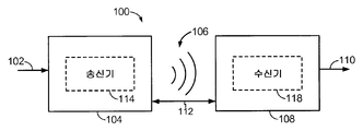
도 1 은 무선 전력 전달 시스템을 단순화하여 도시하는 블록도이다.
도 2 는 무선 전력 전달 시스템을 단순화하여 도시하는 개략도이다.
도 3a 는 본 발명의 예시적 실시예들에서 사용하기 위한 루프 안테나의 개략도이다.
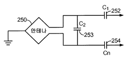
도 3b 는 본 발명의 예시적 실시예들에서 사용되는 차등적 안테나의 대안적인 실시예의 도면이다.
도 4 는 본 발명의 예시적인 실시예에 따른 개장 회로를 가진 전자 디바이스의 도면이다.
도 5 는 본 발명의 예시적인 실시예에 따른 무선 전력공급을 위한 개장 회로를 가진 전자 디바이스의 도면이다.
도 6a 는 본 발명의 예시적인 실시예에 따른 통합형 저장 디바이스의 단면도이다.
도 6b 는 본 발명의 다른 예시적인 실시예에 따른 통합형 저장 디바이스의 단면도이다.
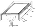
도 6c 는 본 발명의 예시적인 실시예에 따른 통합형 저장 디바이스의 사시도이다.
도 7 은 본 발명의 또 다른 예시적인 실시예에 따른 통합형 저장 디바이스의 도면이다.1 is a simplified block diagram illustrating a wireless power delivery system.
Figure 2 is a simplified schematic diagram of a wireless power delivery system.
3A is a schematic diagram of a loop antenna for use in exemplary embodiments of the present invention.
3B is a diagram of an alternative embodiment of a differential antenna used in exemplary embodiments of the present invention.
4 is a diagram of an electronic device having a remodeling circuit in accordance with an exemplary embodiment of the present invention.
Figure 5 is a diagram of an electronic device with remodeling circuitry for wireless power supply in accordance with an exemplary embodiment of the present invention.
6A is a cross-sectional view of an integrated storage device in accordance with an exemplary embodiment of the present invention.
6B is a cross-sectional view of an integrated storage device in accordance with another exemplary embodiment of the present invention.
6C is a perspective view of an integrated storage device in accordance with an exemplary embodiment of the present invention.
7 is a diagram of an integrated storage device in accordance with another exemplary embodiment of the present invention.
본 명세서에서 "예시적" 이라는 단어는 "예, 사례, 보기로서" 를 의미하는 것으로 사용된다. 본 명세서에 "예시적" 인 것으로 설명되는 어떠한 실시예는 다른 실시예들에 비해 반드시 바람직하거나 유리한 것으로 해석되어서는 아니 된다.The word "exemplary" is used herein to mean "as an example, instance, or illustration. &Quot; Any embodiment described herein as "exemplary " is not necessarily to be construed as preferred or advantageous over other embodiments.
첨부된 도면들과 연결하여 제시되는 이하의 상세한 설명은 본 발명의 예시적인 실시예들의 설명으로 의도된 것이며, 본 발명을 그 실시예들로만 실시할 수 있다는 의미로 의도된 것이 아니다. 본 상세한 설명에 걸쳐 사용되는 "예시적" 이라는 단어는 "예, 사례, 보기로서" 를 의미하며 다른 실시예들에 비해 반드시 바람직하거나 유리한 것으로 해석되어서는 아니 될 것이다. 상세한 설명은 본 발명의 예시적 실시예들의 철저한 이해를 제공하는 목적으로 구체적인 세부점들을 포함한다. 해당 기술분야의 기술자라면 이러한 구체적인 세부점들 없이도 본 발명의 예시적인 실시예들이 실시될 수 있음을 인식할 것이다. 일부 사례들에서는, 본 명세서에 제시되는 예시적 실시예들의 신규성을 모호하게 하는 것을 피하기 위하여, 공지된 구조들 및 디바이스들이 블록도 형태로 도시된다.The following detailed description, taken in conjunction with the accompanying drawings, is intended to be illustrative of the exemplary embodiments of the invention and is not intended to be exhaustive of the invention. The word "exemplary" used throughout this specification shall mean "as an example, instance, or illustration, " and should not necessarily be construed as preferred or advantageous over other embodiments. The detailed description includes specific details for the purpose of providing a thorough understanding of the exemplary embodiments of the invention. Those skilled in the art will recognize that the exemplary embodiments of the present invention may be practiced without these specific details. In some instances, well-known structures and devices are shown in block diagram form in order to avoid obscuring the novelty of the exemplary embodiments presented herein.
본 명세서에서 사용되는 단어들 "무선 전력" 은 전기장, 자기장, 전자기장, 또는 그 외 물리적 전자기 도체들의 사용 없이 송신기에서 수신기로 송신되는 것과 연관되는 어떠한 형태의 에너지를 의미하는 것으로 사용된다.As used herein, the words "wireless power" are used to refer to any form of energy associated with being transmitted from a transmitter to a receiver without the use of electric fields, magnetic fields, electromagnetic fields, or other physical electromagnetic conductors.
도 1 은 본 발명의 다양한 예시적 실시예들에 따른 무선 송신 또는 충전 시스템 (100) 을 도시한다. 송신기 (104) 에는 에너지 전달을 제공하기 위한 방사장 (radiated field) (106) 을 생성하도록 입력 전력 (102) 이 제공된다. 수신기 (108) 는 방사장 (106) 에 커플링하고, 출력 전력 (110) 에 커플링된 디바이스 (미도시) 에 의한 저장 혹은 소비를 위해 출력 전력 (110) 을 생성한다. 송신기 (104) 및 수신기 (108) 양자는 거리 (112) 에 의해 이격되어 있다. 예시적인 일 실시예에서, 송신기 (104) 및 수신기 (108) 는 상호 공진 관계에 따라 구성되며, 수신기 (108) 의 공진 주파수와 송신기 (104) 의 공진 주파수가 정확히 매칭되면, 수신기 (108) 가 방사장 (106) 의 "근거리장 (near-field)" 에 위치할 때 송신기 (104) 와 수신기 (108) 사이의 송신 손실들이 최소화된다.1 illustrates a wireless transmission or
송신기 (104) 는 에너지 송신의 수단을 제공하는 송신 안테나 (114) 를 더 포함하고, 수신기 (108) 는 에너지 수신의 수단을 제공하는 수신 안테나 (118) 를 더 포함한다. 송신 및 수신 안테나들은 이들에 연관될 어플리케이션들 및 디바이스들에 따라 크기가 정해진다. 전술한 바와 같이, 효율적인 에너지 전달은, 에너지의 대부분을 전자기파로서 원거리장으로 전파시키는 것보다는, 에너지의 큰 부분을 송신하는 안테나의 근거리장 내에서 수신하는 안테나에 커플링시킴으로써 발생한다. 근거리장에 있을 때, 송신 안테나 (114) 와 수신 안테나 (118) 사이에 커플링 모드가 개설될 수 있다. 근거리장 커플링이 발생할 수 있는 안테나들 (114 및 118) 주위의 영역은 본 명세서에서 커플링 모드 구역으로 지칭된다.The
도 2 는 무선 전력 전달 시스템을 단순화하여 도시하는 개략도이다. 송신기 (104) 는 발진기 (122), 전력 증폭기 (124), 및 필터 및 매칭 회로 (126) 를 포함한다. 발진기는 원하는 주파수의 발진기 신호를 생성하도록 구성되어 있는데, 이는 조절 신호 (123) 에 응대하여 조절될 수 있다. 발진기 신호는 제어 신호 (125) 에 응대하는 증폭량으로 전력 증폭기 (124) 에 의해 증폭될 수 있다. 고조파 또는 기타 원하지 않는 주파수들을 필터링하고 송신기 (104) 의 임피던스를 송신 안테나 (114) 에 매칭시키도록 필터 및 매칭 회로 (126) 가 포함될 수 있다.Figure 2 is a simplified schematic diagram of a wireless power delivery system. The
수신기 (108) 는 매칭 회로 (132) 및 정류 및 스위칭 회로 (134) 를 포함하여, 도 2 에 도시된 것과 같은 배터리 (136) 를 충전하거나 수신기 (미도시) 에 결합된 디바이스에 전력을 공급하도록 DC 전력 출력을 생성할 수 있다. 수신기 (108) 의 임피던스를 수신 안테나 (118) 에 매칭시키도록 매칭 회로 (132) 가 포함될 수 있다. 본 명세서에서 "배터리" 라는 용어는 저장 전지들 자체에 더해 초과전압 보호 회로들과 같은 부가 물체들을 포함할 수 있다.The
도 3a 에 도시된 바와 같이, 예시적 실시예들에서 사용되는 안테나들은 "루프" 안테나 (150) 로서 구성될 수 있는데, 본 명세서에서 이는 "자기" 안테나로 지칭될 수도 있다. 루프 안테나들은 에어 코어 (air core) 를 포함하거나 강자성 코어와 같은 물리적 코어를 포함하도록 구성될 수 있다. 에어 코어 루프 안테나들은 이종의 (extraneous) 물리적 디바이스들이 코어 근처에 배치되는 것에 대해 더 포용적일 수 있다. 더 나아가, 에어 코어 루프 안테나는 코어 영역 내에 다른 구성요소들의 배치를 허용한다. 또한, 에어 코어 루프는 송신 안테나 (114) (도 2) 의 커플 모드 구역이 보다 강할 수 있는 송신 안테나 (114) (도 2) 의 평면 내에 수신 안테나 (118) (도 2) 의 배치를 보다 용이하게 할 수 있다. As shown in FIG. 3A, the antennas used in the exemplary embodiments may be configured as a "loop" antenna 150, which may be referred to herein as a "magnetic" antenna. The loop antennas may include an air core or be configured to include a physical core such as a ferromagnetic core. Air core loop antennas may be more inclusive for extraneous physical devices to be placed near the core. Further, the air core loop antenna permits placement of other components within the core region. The air core loop also facilitates the placement of the receive antenna 118 (Figure 2) within the plane of the transmit antenna 114 (Figure 2) where the couple mode zone of the transmit antenna 114 (Figure 2) may be stronger .
전술한 바와 같이, 송신기 (104) 와 수신기 (108) 사이에 공진이 매칭 혹은 거의 매칭되었을 때 송신기 (104) 와 수신기 (108) 사이에 효율적인 에너지 전달이 발생한다. 그러나 송신기 (104) 와 수신기 (108) 사이에 공진이 매칭되지 않은 때에도, 에너지는 더 낮은 효율로 전달될 수 있다. 에너지의 전달은, 송신하는 안테나로부터 자유 공간으로 에너지를 전파시키는 것보다는, 송신하는 안테나의 근거리장으로부터 근거리장이 성립된 근방에 소재하는 수신하는 안테나로 에너지를 커플링함으로써 발생한다. As described above, efficient energy transfer occurs between the
루프 혹은 자기 안테나들의 공진 주파수는 인덕턴스 및 캐패시턴스에 기초한다. 루프 안테나에서의 인덕턴스는 일반적으로 루프에 의해 발생된 인덕턴스이고, 캐패시턴스는 일반적으로 루프 안테나의 인덕턴스에 더해져 원하는 공진 주파수의 공진 구조가 만들어진다. 비한정적인 예로서, 캐패시터 (152) 및 캐패시터 (154) 를 안테나에 추가하여 공진 신호 (156) 를 생성하는 공진 회로를 만들 수 있다. 따라서 큰 직경의 루프 안테나들에서는, 루프의 직경 또는 인덕턴스가 증가함에 따라 공진을 유도하는 데 필요한 캐패시턴스의 크기는 감소한다. 더 나아가, 루프 혹은 자기 안테나의 직경이 증가함에 따라, 근거리장의 효율적인 에너지 전달 영역은 증가한다. 물론, 다른 공진 회로들도 가능하다. 또 하나의 비한정적인 예로서, 캐패시터가 루프 안테나의 두 터미널들 사이에 병렬로 배치될 수 있다. 또한, 해당 기술분야에서 통상의 지식을 가진 자라면 송신 안테나들에서 공진 신호 (156) 가 루프 안테나 (150) 로의 입력일 수 있음을 인식할 것이다.The resonant frequencies of the loop or magnetic antennas are based on inductance and capacitance. The inductance in the loop antenna is generally the inductance generated by the loop, and the capacitance is generally added to the inductance of the loop antenna to create the resonant structure of the desired resonant frequency. As a non-limiting example, a capacitor 152 and a capacitor 154 may be added to the antenna to create a resonant circuit that produces a resonant signal 156. Thus, in large diameter loop antennas, as the diameter or inductance of the loop increases, the magnitude of the capacitance required to induce resonance decreases. Furthermore, as the diameter of the loop or magnetic antenna increases, the effective energy transfer area of the near field increases. Of course, other resonant circuits are possible. As another non-limiting example, a capacitor may be placed in parallel between two terminals of the loop antenna. Those skilled in the art will also recognize that the resonant signal 156 at the transmit antennas may be an input to the loop antenna 150.
도 3b 는 본 발명의 예시적 실시예들에서 사용되는 차등적 안테나 (250) 의 대안적인 실시예를 도시한다. 안테나 (250) 는 차등적 코일 안테나로 구성될 수 있다. 차등적 안테나 구성에서는, 안테나 (250) 의 중심이 접지에 연결된다. 안테나 (250) 는, 도 3a 에서처럼 일단이 접지에 연결되는 것 대신, 양단이 수신기/송신기 유닛 (미도시) 에 연결된다. 안테나 (250) 에는 차등적 공진 신호를 생성하는 공진 회로를 만들도록 캐패시터들 (252, 253, 254) 이 추가될 수 있다. 차등적 안테나 구성은 통신이 양방향성이고 코일로의 송신이 요구되는 상황들에서 유용할 수 있다. 이러한 상황 한 가지로는 근거리장 통신 (NFC) 시스템들의 경우를 들 수 있다. FIG. 3B illustrates an alternative embodiment of a
본 발명의 예시적 실시예들은 서로의 근거리장들에 있는 두 안테나들 사이에 전력을 커플링하는 것을 포함한다. 전술한 바와 같이, 근거리장은 전자기장들이 존재하지만 안테나로부터 멀어지게 전파 또는 방사될 수 없는 안테나 주위의 영역이다. 근거리장은 통상적으로 안테나의 물리적 부피 근처의 부피로 한정된다. 본 발명의 예시적 실시예들에서, 단회전 및 다회전 루프 안테나들과 같은 자기형 안테나들이 송신 (Tx) 및 수신 (Rx) 안테나 시스템들 모두에서 사용되는데, 자기형 안테나들에서의 근거리 자기장 진폭들이 전기형 안테나 (예컨대, 소형 다이폴) 의 근거리 전기장에 비해 높은 경향이 있어 두 시스템들 사이에 잠재적으로 더 높은 커플링을 허용하기 때문이다. 그러나 "전기" 안테나들 (예컨대, 다이폴들 및 모노폴들) 또는 자기 및 전기 안테나들의 조합도 본 발명의 범위 내에 속하는 것으로 사료된다.Exemplary embodiments of the present invention include coupling power between two antennas in short-range fields of each other. As discussed above, the near field is the area around the antenna where electromagnetic fields exist but can not propagate or radiate away from the antenna. The near field is typically limited to a volume near the physical volume of the antenna. In the exemplary embodiments of the present invention, magnetic antennas, such as single-turn and multi-turn loop antennas, are used in both transmit (Tx) and receive (Rx) antenna systems where the near- Because they tend to be higher than the near field of an electrical antenna (e.g., a small dipole), potentially allowing a higher coupling between the two systems. However, it is understood that "electrical" antennas (e.g., dipoles and monopoles) or a combination of magnetic and electrical antennas are also within the scope of the present invention.
Tx 안테나는 전술한 원거리장 및 유도성 접근법들이 허용하는 것에 비해 현저히 더 큰 거리들에서 소형 Rx 안테나에 대해 우수한 커플링 (예컨대, > -4 dB) 을 획득하기에 충분히 낮은 주파수로, 그리고 충분히 큰 안테나 크기로 동작될 수 있다. Tx 안테나의 크기가 올바르게 결정되면, 구동되는 Tx 루프 안테나의 커플링 모드 구역 (즉, 근거리장) 내에 호스트 디바이스 상의 Rx 안테나가 배치될 때 높은 커플링 수준들 (예컨대, -1 내지 -4 dB) 을 획득할 수 있다.The Tx antenna is designed to have a frequency sufficiently low to obtain good coupling (e.g., > -4 dB) for a small Rx antenna at significantly greater distances than that allowed by the far field and inductive approaches described above, Antenna size. (E.g., -1 to -4 dB) when the Rx antenna on the host device is placed in the coupling mode zone (i.e., near field) of the driven Tx loop antenna, if the size of the Tx antenna is correctly determined, Can be obtained.
미래에는 전자 디바이스들이 무선 전력공급 및/또는 NFC 내장된 채 제조될 수 있다. 그러나 현재에는 무선 전력공급 기능이 없고 NFC 기능이 없는, 일반 폐기용 또는 재충전가능 배터리들을 사용하는 전자 디바이스들이 다수 사용되고 있다. 본 발명의 실시예들은 원래에는 무선 전력공급 기술 또는 NFC 가 내장되지 않았던 전자 디바이스들을 개장하는 실시예들을 포함하는데, 사용자들에게는 아직도 이러한 구식 전자 디바이스들이 존재한다. 이러한 실시예들에는 맞춤식 배터리 팩, 맞춤식 대체 하우징, 표준 배터리 팩의 개장 등이 포함된다.In the future, electronic devices can be manufactured with wireless power supply and / or embedded NFC. However, nowadays, many electronic devices that do not have a wireless power supply function and do not have NFC function and use general waste or rechargeable batteries are used. Embodiments of the present invention include embodiments that originally rework electronic devices that did not have wireless power supply technology or NFC built in, but still there are these old electronic devices for users. These embodiments include customized battery packs, customized alternate housings, retrofit of standard battery packs, and the like.
본 명세서에서 사용되는 "개장" 이라 함은, 기존 배터리 및 배터리 캐비티를 가지고 기존 배터리를 전자 디바이스 내에 지니기 위한 폼 팩터를 가지는 기존 전자 디바이스를, 기존 배터리를 충전하거나 기존 배터리 대체용으로서 전자 디바이스들 내에 설치된 새로운 배터리를 충전하기 위한 추가적인 기능성을 포함하도록 수정하는 것을 의미한다."Refurbishment" as used herein refers to the replacement of an existing electronic device having a form factor for holding an existing battery with an existing battery and battery cavity in the electronic device, within the electronic devices And to include additional functionality to charge the installed new battery.
도 4 는 본 발명의 예시적인 실시예에 따른 개장 회로를 가진 전자 디바이스 (400) 를 도시한다. 전자 디바이스 (400) 는 무선 전력 수신 안테나 (420) 및 변환 회로 (430) 를 가지는 백 하우징 (410) 을 포함할 수 있다. 전자 디바이스 (400) 는 전자 디바이스 (400) 를 위한 내부 전자 회로 (미도시) 를 포함하는 프론트 하우징 (440) 과 배터리 (450) 를 포함할 수 있다. 도 4 에 도시된 바와 같이, 백 하우징 (410) 은 프론트 하우징 (440) 으로부터 제거될 수 있다. 프론트 하우징 (440) 으로부터 백 하우징 (410) 이 제거 및 분리되면, 배터리 (450), 안테나 (420), 및 변환 회로 (430) 는 노출될 수 있다. 안테나 (420) 는 백 하우징 (410) 에 배치되거나 통합형으로 형성될 수 있다. 안테나 (420) 및 변환 회로 (430) 는 프론트 하우징 (440) 과는 별도로 백 하우징 (410) 과 함께 제조될 수 있다. 이에 따라, 백 하우징 (410) 은 기존 전자 디바이스들에 맞도록, 그리고 원래에는 무선 전력공급 기능이 없었던 전자 디바이스들의 상응하는 원래의 하우징부들을 대체하도록 구성될 수 있다. 4 illustrates an
안테나 (420) 및 변환 회로 (430) 는 외부 디바이스로부터 신호를 수신 및 변환하도록, 그리고 원래에는 안테나 (420) 또는 변환 회로 (430) 를 포함하지 않았던 전자 디바이스를 개장하도록 구성될 수 있다. 외부 소스는 무선 전력 송신기일 수 있으며, 안테나 (420) 및 변환 회로 (430) 는 신호를 수신 및 변환하여 전자 디바이스 (400) 를 위한 무선 전력을 생성하도록 더 구성될 수 있다. 이에 따라, 변환 회로 (430) 는 매칭 회로 (132) 및 정류 회로 (134) (도 2) 와 같은 무선 전력 수신 회로를 포함할 수 있다. 안테나 (420) 및 변환 회로 (430) 는 전자 디바이스가 NFC 데이터를 전송 및 수신할 수 있게 하도록 구성될 수도 있다.The
NFC 를 위한 예시적 통신 메커니즘들 및 프로토콜들의 세부점들은 2008년 10월 10일에 출원되고 발명의 명칭이 "무선 전력 환경에서의 충전 신호 (SIGNALING CHARGING IN WIRELESS POWER ENVIRONMENT)" 인 미국 특허 출원 제 12/249,866 호에서 볼 수 있으며, 이 출원 전부는 본 명세서에 참조로서 통합된다.Details of exemplary communication mechanisms and protocols for NFC are disclosed in U.S. Patent Application No. 12 (1990), filed October 10, 2008, entitled " SIGNALING CHARGING IN WIRELESS POWER ENVIRONMENT " / 249,866, the entire disclosures of which are incorporated herein by reference.
안테나 (420) 주위의 자기장 생성을 가능하게 하고 그 성능을 향상시키기 위해, 안테나 (420) 는 (다른 안테나들 또는 접지면들과 같은) 금속 장애물들 주위로 클리어런스 (clearance) 을 가지도록 라우팅 (routed) 될 수 있다. 일 실시예에서는, 변환 회로 (430) 가 ASIC 와 같은 별개의 (discrete) 구성요소로 구성될 수 있다. 동작 중에, 전자 디바이스 (400) 는 송신 안테나 (미도시) 의 범위 내에 배치될 수 있고, 배터리 (450) 가 전자 디바이스 (400) 로부터 제거되거나 전자 디바이스 (400) 가 AC 콘센트에 연결될 필요 없이 배터리 (450) 가 충전될 수 있다.To enable magnetic field generation around the
동작시, 백 하우징 (410) 은 변환 회로 (430) 와 배터리 (450) 사이에 전기적 연결이 이루어지는 방식으로 프론트 하우징 (440) 에 연결되도록 구성될 수 있다. 변환 회로 (430) 와 배터리 (450) 사이의 전기적 연결은 변환 회로 (430) 의 접점들이 배터리 (450) 의 접점들과 접촉하여 전기 연결을 구축함으로써 이루어질 수 있다. (도 5 에 도시된 것과 같은) 대안적인 예시적 실시예는 변환 회로 (430) 로부터 연장하여 배터리 (450) 의 접점들과 전기적 접속을 구축하는 (케이블과 같은) 커넥터를 포함할 수 있다. 배터리 (450) 는 원래 전자 디바이스 (400) 를 동작시키도록 의도된 배터리일 수 있으나, 배터리 (450) 는 전자 디바이스 (400) 의 기존 배터리를 위한 폼 팩터에 맞고, 변환 회로 (430) 에 연결되고, 필요한 경우 안테나 (420) 및 변환 회로 (430) 를 위한 공간을 허용하도록 맞춤식으로 만들어질 수 있다.In operation, the
다른 예시적 실시예에서, 안테나 (420) 및 변환 회로 (430) 는, 예를 들면 키트 (kit) 의 형태로서, 백 하우징 (410) 과는 별도로 제조될 수 있다. 이러한 키트는 곧이어 원래에는 무선 전력 충전 또는 NFC 능력들이 없이 만들어진 전자 디바이스 (400) 내로 개장될 수 있다. 안테나 (420) 및 변환 회로 (430) 를 포함하는 키트는 전자 디바이스 (400) 에, 예를 들면 원래의 백 하우징 (410) 에, 부착되거나 포함되도록 구성될 수 있다. 이러한 부착 행위들은 사용자, 전자 디바이스 (400) 의 제공자, 또는 관련된 다른 주체에 의해 수행될 수 있다.In another exemplary embodiment,
배터리들이 재충전가능한지 결정하기 위해, 충전 디바이스 (즉, 개장된 안테나 (420) 및 변환 회로 (430)) 는 무선 충전 NFC 또는 기타 단거리 통신들 (예컨대, 지그비, 블루투스 등) 을 통해 전자 디바이스 (400) 와 통신하여 저장 전지들이 재충전을 위해 적합한지 (즉, 1차 전지들이 아닌지) 결정할 수 있다. 충전 디바이스는 또한 적절한 충전 프로토콜을 적용하기 위해 전자 디바이스 (400) 와 통신하여 배터리 기술 (예컨대, 니켈 카드뮴, 니켈 금속수소화물, 리튬 이온 등) 을 결정할 수도 있다.The charging device (i.e., the refurbished
예시의 목적으로, 전자 디바이스 (400) 는 도 4 에 도시된 것과 같은 셀폰일 수 있다. 그러나 해당 기술분야에서 통상의 지식을 가진 자라면 본 발명의 예시적 실시예들이 이러한 전자 디바이스들로 한정되는 것은 아님을 인식할 것이다. 그 외의 전자 디바이스들에는 PDA (personal digital assistants), 오디오/비디오 디바이스, 카메라, 배터리에 의해 전력 공급되는 전동도구, 리모콘 (remote controls), 컴퓨터 마우스, 랩탑 컴퓨터, 및 기타 배터리에 의해 전력 공급되는 전자 디바이스들이 포함된다.For purposes of illustration, the
도 5 는 본 발명의 예시적인 실시예에 따른 무선 전력공급을 위한 개장 회로를 가진 전자 디바이스 (500) 를 도시한다. 전자 디바이스 (500) 는 무선 전력 수신 안테나 (520) 및 무선 전력 수신 회로 (530) 를 가지는 백 하우징 (510) 을 포함할 수 있다. 전자 디바이스 (500) 는 전자 디바이스 (500) 의 동작을 위한 내부 전자 회로 (미도시) 를 포함하는 프론트 하우징 (540), 배터리 (미도시), 및 차폐기 (550) 를 포함할 수 있다. 도 5 에 도시된 바와 같이, 차폐기 (550) 는 배터리를 덮는다. 차폐기 (550) 는 배터리를 감쌀 수 있는 금속 케이싱으로부터 안테나를 격리시키도록 구성될 수 있는데, 이에 대해서는 이후에 보다 상세히 설명될 것이다.FIG. 5 illustrates an
도 5 에 도시된 바와 같이, 백 하우징 (510) 은 프론트 하우징 (540) 으로부터 제거될 수 있다. 프론트 하우징 (540) 으로부터 백 하우징 (510) 이 제거 및 분리되면, 차폐기 (550), 무선 전력 수신 안테나 (520), 및 무선 전력 수신 회로 (530) 는 노출될 수 있다. 무선 전력 수신 안테나 (520) 는 백 하우징 (510) 에 배치되거나 통합형으로 형성될 수 있다. 무선 전력 수신 안테나 (520) 및 무선 전력 수신 회로 (530)는 프론트 하우징 (540) 과는 별도로 백 하우징 (510) 과 함께 제조될 수 있다. 이에 따라, 백 하우징 (510) 은 기존 전자 디바이스들에 맞도록, 그리고 원래에는 무선 전력공급 기능이 없었던 전자 디바이스들의 상응하는 원래의 백 하우징들을 대체하도록 구성될 수 있다. As shown in FIG. 5, the
동작시, 백 하우징 (510) 은 무선 전력 수신 회로 (520) 와 배터리 사이에 전기적 연결이 이루어지는 방식으로 프론트 하우징 (540) 에 연결되도록 구성될 수 있다. 무선 전력 수신 회로 (520) 와 배터리 사이의 전기적 연결은 무선 전력 수신 회로 (520) 의 접점들이 배터리의 접점들과 전기적으로 접속하여 전기 연결을 구축함으로써 이루어질 수 있다. 대안적으로는, 도 5 에 도시된 바와 같이 전자 디바이스 (500) 가, 무선 전력 충전 중에 배터리를 충전하기 위하여, 무선 전력 수신 회로 (520) 로부터 연장하고 차폐 (550) 를 통과하여 배터리의 접점들과 전기적 연결을 구축하는 (케이블과 같은) 커넥터 (560) 를 포함할 수 있다.In operation, the
도 6a 는 본 발명의 예시적인 실시예에 따른 통합형 저장 디바이스 (600) 의 단면도이다. 통합형 저장 디바이스 (600) 는 공통 하우징 봉입체 (610) 내에 저장 전지들 (620), 안테나 (630), 차폐기 (640), 및 기타 회로 (650) 를 포함한다.6A is a cross-sectional view of an
공통 하우징 봉입체 (610) 는 전자 디바이스에 사용되는 일반 배터리와 동일한 폼 팩터로 형상 및 치수가 정하여질 수 있다. 그러면 통합형 저장 디바이스 (600) 는 원래의 배터리를 대신하여 전자 디바이스 내에 삽입되어 송신 안테나 (미도시) 로부터 무선 전력으로 충전될 수 있는 배터리 (즉, 저장 전지들 (620)) 를 전자 디바이스에 제공할 수 있다. 통합형 저장 디바이스는 전술한 바와 같이 NFC 능력들을 포함할 수도 있다.The common
커넥터 (660) 는 전자 디바이스에 전력을 제공하기 위해 전자 디바이스의 원래 배터리와 유사한 방식으로 전자 디바이스와 전기적 접속들을 만들도록 구성될 수 있다. 커넥터 (660) 는 도 6a 내지 도 6c 에 도시된 것과 같은 케이블일 수 있으며, 또는 대안적으로 보통의 배터리가 전자 디바이스에 전력을 공급하기 위해 접속할 접점들과 전기적 연결을 구축하는 일 세트의 접점들일 수 있다.The
안테나 (630) 는, 코일 안테나와 같이, 무선 전력 및 NFC 을 수신하도록 구성될 수 있다. 달리 표현하자면, 안테나는 무선 전력 송신들 또는 NFC 송신들을 또는 그 둘의 조합을 수신하도록 구성될 수 있다. 둘 모두를 수신하도록 구성된 경우, 안테나 (630) 는 무선 전력공급 시스템 및 전자 디바이스의 원래 전자계 양자에 의해 공유될 수 있는데, 이는 현재 그러한 능력들을 가지고 있지 않은 기존 전자 디바이스들에서 무선 전력공급 및 NFC 를 통합시키는 경제적인 방법일 수 있다.The
저장 전지들 (620) 은 임의의 종류의 배터리 저장 전지들로 구성될 수 있는데, 예를 들어 리튬 이온 배터리일 수 있다. 통합형 저장 디바이스 (620) 의 공통 하우징 봉입체 (610) 는 추가 회로를 가지면서도 전자 디바이스의 기존 배터리를 대체하도록 구성될 수 있으므로, 저장 전지들 (620) 의 물리적 영역은 전자 디바이스 내에서 통합형 저장 디바이스 (600) 대체할 기존 배터리 내의 상응하는 저장 전지들보다 물리적으로 작을 수 있다. 그러나 저장 전지들 (620) 은 이전 배터리의 저장 전지들에 비해 전기적으로 동일하거나 더 클 수 있다.
차폐기 (640) 는 저장 전지들 (620) 과 안테나 (630) 사이에 위치하는, 자기장을 형성하는 보호 재료일 수 있다. 차폐기 (640) 는 저장 전지들 (620) 을 감쌀 수 있는 금속 케이싱으로부터 안테나를 격리시키도록 구성될 수 있다. 달리 표현하자면, 차폐기 (640) 는 자기장을 국부화시켜 저장 전지들 (620) 이 안테나 (630) 의 성능에 미칠 수 있는 방해성 효과들을 감소시키는 효과를 가질 수 있다. 차폐기는, 예컨대 일본 도쿄의 TDK 사에서 입수가능한 FLEXIELD 와 같은, 페라이트 (ferrite) 재료로 만들어질 수 있다.The
기타 회로 (650) 는 무선 전력공급 기능을 가지도록, 또는 NFC 기능을 가지도록, 또는 무선 전력공급 기능 및 NFC 기능을 모두 가지도록 전자 디바이스를 변환하는 능력을 통합형 저장 디바이스 (600) 에 제공할 수 있다. 이러한 회로의 예로는 도 2 에 관하여 전술한 매칭 회로 및 정류 회로가 포함된다. 기타 회로 (650) 는 또한, 초과 보호 회로가 저장 전지들 (620) 에 내장되어 있지 않다면, 초과전압 보호 회로를 포함할 수도 있다.
이에 더해, 통합형 저장 디바이스 (600) 는 표시기 (예컨대, 시각적 또는 청각적) 를 포함할 수 있으며, 이는 연관 전자 디바이스가 무선 전력 송신 충전장의 범위 내에 있을 때 활성화 (예컨대, 발광다이오드로부터 광이 깜빡이거나 어떠한 청각적 표시를 통해) 될 수 있다. 통합형 저장 디바이스 (600) 는 또한, 자기장에 대한 추가적 로버스트성을 위해, 구성요소들을 감싸는 자기적으로 투명한 포장 재료를 포함할 수도 있다.In addition, the
동작시, 통합형 저장 디바이스 (600) 는 무선 전력 충전기의 송신기에 의해 생성되는 방사장 내에 있을 때 무선 전력을 수신하도록 구성될 수 있다. 무선 전력은 배터리와 같은 저장 전지들 (620) 내에 저장될 수 있다. 그러면 저장 전지들 (620) 로부터의 저장된 전하는 연관 전자 디바이스에 전력을 공급하는 데 사용될 수 있다. 대안적으로, 통합형 무선 저장 디바이스 (600) 에 의해 수신되는 전력은, 저장 전지들 (620) 에 저장되는 대신, 전자 디바이스에 직접 전력을 공급할 수 있다. 달리 표현하자면, 일 사용행태는 전자 디바이스에 전력을 공급하기 위한 저장 전지들 (620) 을 충전하는 것일 수 있고, 다른 사용행태는 전자 디바이스가 송신 안테나의 방사장 범위 내에 있는 경우 전자 디바이스에 직접 전력을 공급하는 것일 수 있다. 전술한 바와 같이, 무선 충전에는 송신하는 안테나가 충전될 전자 디바이스 내의 수신 안테나에 전력을 공급하고, 이어서 수신된 전력을 DC 전력으로 변환하는 정류 회로를 급전하는 것이 포함된다. DC 전력은 전자 디바이스의 배터리를 충전하거나 동시 동작을을 위한 전력을 제공할 수 있다. 일반적으로는, 통합형 저장 디바이스 (600) 가 수신 안테나 (630), 저장 전지들 (620) (예컨대, 배터리), 및 기타 회로 (650) (예컨대, 정류 회로와 또한 충전하는 송신 안테나에 신호를 보내기 위한 회로들) 를 전자 디바이스의 기존 배터리 팩을 대체하는 공통의 하우징 봉입체 (610) 내로 조합시킬 수 있다. In operation, the
대안적으로, 혹은 부가적으로, 통합형 저장 디바이스 (600) 는 전자 디바이스가 안테나 (630) 를 통해 NFC 를 전송 및 수신할 수 있게 하도록 구성될 수 있다. 기존 배터리 팩을 대체하도록 통합형 저장 디바이스 (600) 를 사용함으로써, 전자 디바이스는 소프트웨어 수정을 요구하지 않을 수 있다. 통합형 저장 디바이스 (600) 의 사용은 유리할 수 있는데, 다수의 전자 디바이스들은 전자 디바이스가 특정 전자 디바이스에 대한 맞춤식 AC 어댑터에 의해서만 충전될 수 있게 하는 맞춤식 소프트웨어를 가지기 때문이다. 기존 배터리 터미널에서 직접 충전하는 것은 이러한 소프트웨어 호환성 문제들을 완화시킬 수 있는데, 전자 디바이스 내의 소프트웨어에게는 전력이 일반 배터리에 의해 제공되는 것처럼 보일 것이기 때문이다. 이에 더해, 통합형 저장 디바이스 (600) 가 전자 디바이스의 기존 배터리의 크기 및 형상에 부합하도록 구성될 수 있기 때문에, 전자 디바이스 원래의 산업적 디자인이 유지될 수 있다. 이에 더해, 통합형 저장 디바이스 (600) 는 사용자가 기존 배터리 팩을 통합형 저장 디바이스 (600) 로 대체함으로써 현재의 전자 디바이스를 간단한 방법으로 업그레이드하게 할 수 있다.Alternatively, or in addition, the
공통 하우징 봉입체 (610) 를 가진 통합형 저장 디바이스 (600) 는 상이한 통합형 저장 디바이스들 (600) 에 걸쳐 보다 일정한 공진을 유지하는 것을 가능하게 할 수 있다. 안테나 (630), 차폐기 (640), 및 저장 전지들 (620) 의 상대적 위치들 및 간격은 안테나 (630) 의 올바른 튜닝에 현저히 기여할 수 있다. 구성요소들 (예컨대, 저장 전지들 (620), 안테나 (630), 차폐기 (640) 등) 이 느슨하게 (loose) 있으면, 이러한 구성요소들 사이의 다양한 간격은 상이한 공진 주파수들이 얻어질 수 있다. 달리 표현하자면, 통합형 저장 디바이스 (600) 를 제공하면 무선 전력공급 또는 NFC 통신의 성능이 보다 신뢰성 있고 반복 가능하게 될 수 있다.An
도 6b 는 본 발명의 다른 예시적인 실시예에 따른 통합형 저장 디바이스 (600) 의 단면도이다. 통합형 저장 디바이스 (600) 는 커넥터 (660) 를 가진 공통 하우징 봉입체 (610) 내에 저장 전지들 (620), 안테나 (630), 차폐기 (640), 및 기타 회로 (650) 를 포함하며, 각각은 도 6a 에서와 같이 구성되어 있다. 통합형 저장 디바이스 (600) 는 추가적으로 수신 회로 (670) 를 포함하는데, 이는 기타 회로 (650) 와는 상이한 모듈 내에 있을 수 있다. 수신 회로 (670) 는 무선 전력공급 및/또는 NFC 변환과 관련된 회로를 포함할 수 있다. 이러한 회로의 예들에는 안테나 (630) 에 의해 수신된 전력을 DC 전력으로 변환하는 정류기, 필터, 및 조정기가 포함될 수 있다.6B is a cross-sectional view of an
도 6c 는 본 발명의 예시적인 실시예에 따른 통합형 저장 디바이스 (600) 의 사시도이다. 통합형 저장 디바이스 (600) 는 커넥터 (660) 를 가진 공통 하우징 봉입체 (610) 내에 저장 전지들 (620), 안테나 (630), 차폐기 (640), 및 기타 회로 (650) 를 포함하며, 각각은 도 6a 에서와 같이 구성되어 있다. 무선 전력 변환, NFC, 또는 그 조합을 위한 회로는 기타 회로 (650) 에 포함되거나, 도 6b 에 도시된 것과 같은 다른 모듈 (670) 내에 포함될 수 있다. 대안적으로는, NFC 및/또는 무선 전력 변환을 위한 회로가 통합형 저장 디바이스 (600) 의 외부에 수용될 수 있는데, 이와 같이 하는 데에는 통합형 저장 디바이스 (600) 외부에 안테나 (630) 연결들이 존재하는 것이 요구될 수 있다.6C is a perspective view of an
도 7 은 본 발명의 또 다른 예시적인 실시예에 따른 통합형 저장 디바이스 (700) 를 도시한다. 통합형 저장 디바이스 (700) 는 기존 배터리의 형상 및 크기 (즉, 동일한 폼 팩터에 맞도록) 로 구성되고, 기존 배터리와 동일한 전극 연결들을 가지도록 구성될 수 있다. 예를 들어, 전자 디바이스가 AA 배터리들 (701 및 702) 과 같은 폐기용 배터리들에 의해 전력을 공급받을 수 있다. 이러한 배터리 종류들은 흔히 손전등 또는 완구와 같은 휴대용 전자 물체의 배터리 격납부에 사용될 수 있다. 본 예시적 실시예에서, 개장 배터리들 (701 및 702) 은 코일 안테나 (705) 를 포함하는데, 이는 배터리들 (701, 702) 의 외주면들 중 하나 혹은 둘 모두의 가장자리 주위로 배치될 수 있다. 이에 더해, 개장 배터리들 (701 및 702) 의 일부는 정류기, 필터, 조정기, 및 디바이스가 무선 전력, NFC, 또는 그 조합을 수신할 수 있게 하는 데 필요한 기타 회로를 포함하는 전자 회로 (710) 로 형성될 수 있다. 연관 전자 디바이스를, 또는 개장 배터리들 (701, 702) 을 별도로 송신 안테나의 커플링 모드 구역에 배치함으로써, 배터리 (702) 의 나머지 부분의 저장 전지들 (일반적으로 712, 714, 716 로 표시됨) 은 무선으로 충전될 수 있다.Figure 7 illustrates an
그러므로 통합형 저장 디바이스 (700) 는 공통 하우징 내에 양 저장 전지들 (712, 714, 716), 코일 안테나 (705), 및 연관 전자 회로(710) 을 포함한다. 통합형 저장 디바이스 (700) 는, 새 무선충전 배터리 어셈블리에 의한 대체 배터리의 무선 충전을 가능하게 함으로써, 전자 디바이스가 무선 전력 수신에 따라 동작하도록 또는 NFC 기능이 가능해지도록 전자 디바이스를 개장하는 데 사용될 수 있다. 배터리 내의 저장 전지들이 사용하는 물리적 공간은 감소될 수 있는데, 배터리의 일부 영역이 추가적 전자 회로들을 위해 예비될 수 있기 때문이다. 그러나 배터리의 전기적 성능은 대체되는 기존 배터리들과 실질적으로 유사할 수 있다. 도 7 에는 AA 배터리들이 도시되었지만, 이러한 예시적 배터리 형상들 및 크기들은 한정적인 것으로 여겨져서는 아니 된다. 통합형 저장 디바이스들은, 예를 들면, AA, AAA, C 셀, D 셀, 9-Volt, 리튬 이온, 니켈 카드뮴, 및 니켈 금속 수소화물 배터리들처럼, 어떠한 종류의 배터리로든 그 형상 또는 크기가 정해지도록 구성될 수 있다.
다른 예시적 실시예에서는, 어떠한 기존 전자 디바이스들의 하우징들이 너무 두껍거나 너무 많은 내부적 차폐를 제공할 수 있고, 이는 무선 충전장이 기존 전자 디바이스의 하우징을 투과하지 못하게 할 수 있다. 이러한 다른 예시적 실시예에서는, 도 4 내지 도 7 에서와 같은 무선 전력공급 기능을 가진 배터리들이 전자 디바이스로부터 제거되어 무선 전력장 내에, 예를 들면 충전 패드 상에, 배치될 수 있다. 이러한 배터리를 제거하는 것은 차폐된 영역으로부터 배터리를 제거하여 무선 커플링이 발생하는 것을 가능하게 할 수 있다. 무선 전력 수신을 통해 충전이 되면, 무선 전력공급 기능을 가진 배터리들이 전자 디바이스 내에 다시 배치될 수 있다.In another exemplary embodiment, the housings of any existing electronic devices may provide too thick or too much internal shielding, which may prevent the wireless charging station from penetrating the housing of the existing electronic device. In these other exemplary embodiments, batteries having a wireless power supply function as in FIGS. 4-7 may be removed from the electronic device and placed in a wireless power field, for example on a charging pad. Removing such a battery may remove the battery from the shielded area to enable wireless coupling to occur. Once charged via wireless power reception, batteries with a wireless power supply function can be repositioned in the electronic device.
다른 예시적 실시예에서, 무선 전력 변환 하드웨어가 전자 디바이스에 외부적으로, 예컨대 전자 디바이스로의 DC 입력단에서, 연결되는 디바이스로 구성될 수 있다.In another exemplary embodiment, the wireless power conversion hardware may be configured externally to the electronic device, e.g., a device that is connected at the DC input to the electronic device.
본 명세서에서 설명된 접근법은 CDMA, WCDMA, OFDM, 802.11, GPS, 블루투스, LGE 등과 같은 다양한 통신 규격들에 적용 가능하다. 해당 기술분야에서 통상의 지식을 가진 자라면 다양한 기술들 및 기법들을 어떠한 것이든 사용하여 정보 및 신호들이 표현될 수 있음을 인식할 것이다. 예를 들어, 본 상세한 설명에 걸쳐 언급된 데이터, 지시어, 명령, 정보, 신호, 비트, 기호, 및 칩은 전압, 전류, 전자기파, 자기장 혹은 자기입자, 광학장 혹은 광입자, 또는 이들의 어떠한 조합으로 표현될 수 있다.The approaches described herein are applicable to a variety of communication standards such as CDMA, WCDMA, OFDM, 802.11, GPS, Bluetooth, LGE, and the like. Those of ordinary skill in the art will recognize that information and signals may be represented using any of a variety of techniques and techniques. For example, data, instructions, instructions, information, signals, bits, symbols, and chips referred to throughout this specification may be represented by voltages, currents, electromagnetic waves, magnetic fields or particles, optical fields or light sources, Can be expressed.
해당 기술분야에서 통상의 지식을 가진 자라면 본 명세서에 개시된 예시적 실시예들과 연계하여 설명된 다양한 예시적 논리 블록, 모듈, 회로, 및 알고리즘 단계들이 전자 하드웨어, 컴퓨터 소프트웨어, 또는 그 조합으로 구현될 수 있음을 이해할 것이다. 하드웨어 및 소프트웨어의 상호교환성을 명확히 나타내기 위하여, 다양한 예시적 구성요소, 블록, 모듈, 회로, 및 단계는 상기에서 그 기능성 측면으로 일반적으로 설명되었다. 이러한 기능성이 하드웨어로 또는 소프트웨어로 구현될 것인지 여부는 전체 시스템에 부여된 특정 어플리케이션 및 디자인 제약들에 의존한다. 숙련된 기술자들은 설명된 기능성을 특정 어플리케이션 각각에 대해 다양한 방법들로 구현할 수 있으나, 이러한 구현형태 선택들이 본 발명의 예시적 실시예들의 범위에서 벗어나는 것으로 해석되어서는 아니 된다. Those skilled in the art will appreciate that the various illustrative logical blocks, modules, circuits, and algorithm steps described in connection with the exemplary embodiments disclosed herein may be implemented as electronic hardware, computer software, It will be appreciated. In order to clearly illustrate the interchangeability of hardware and software, various illustrative components, blocks, modules, circuits, and steps have been described above generally in terms of their functionality. Whether such functionality will be implemented in hardware or in software depends upon the particular application and design constraints imposed on the overall system. Skilled artisans may implement the described functionality in varying ways for each particular application, but such implementation choices should not be interpreted as causing a departure from the scope of the exemplary embodiments of the present invention.
본 명세서에 개시된 예시적 실시예들과 연계하여 설명된 다양한 예시적 논리 블록, 모듈, 및 회로는 본 명세서에 설명된 기능들을 수행하도록 설계된 범용 프로세서, 디지털 신호 프로세서 (DSP), 어플리케이션 전용 집적 회로 (ASIC), 필드 프로그래머블 게이트 어레이 (FPGA), 또는 기타 프로그래머블 로직 디바이스, 이산 게이트 또는 트랜지스터 로직, 이산 하드웨어 컴포넌트, 또는 이들의 어떠한 조합으로 구현 또는 수행될 수 있다. 범용 프로세서는 마이크로프로세서일 수 있으나, 대안적으로는, 프로세서가 임의의 종래 프로세서, 제어기, 마이크로컨트롤러, 또는 상태 기계일 수 있다. 프로세서는 또한 컴퓨팅 디바이스들의 조합으로서 구현될 수 있는데, 예를 들면, DSP 및 마이크로프로세서의 조합, 복수의 마이크로프로세서, DSP 코어와 연동하는 하나 이상의 마이크로프로세서, 또는 이와 같은 임의의 다른 구성으로서 구현될 수 있다.The various illustrative logical blocks, modules, and circuits described in connection with the exemplary embodiments disclosed herein may be implemented or performed with a general purpose processor, a digital signal processor (DSP), an application specific integrated circuit ASICs, field programmable gate arrays (FPGAs), or other programmable logic devices, discrete gate or transistor logic, discrete hardware components, or any combination thereof. A general purpose processor may be a microprocessor, but, in the alternative, the processor may be any conventional processor, controller, microcontroller, or state machine. A processor may also be implemented as a combination of computing devices, for example, a combination of a DSP and a microprocessor, a plurality of microprocessors, one or more microprocessors in conjunction with a DSP core, or any other such configuration. have.
본 명세서에 개시된 예시적 실시예들과 연계하여 설명된 방법 또는 알고리즘의 단계들은 직접적으로 하드웨어로, 또는 프로세서에 의해 실행되는 소프트웨어 모듈로, 또는 이 둘의 조합으로 구체화될 수 있다. 소프트웨어 모듈은 랜덤 액세스 메모리 (RAM), 플래시 메모리, 리드 온리 메모리 (ROM), 전기적 프로그래머블 ROM (EPROM), 전기적 소거가능 프로그래머블 ROM (EEPROM), 레지스터, 하드 디스크, 제거가능 디스크, CD-ROM, 또는 해당 기술분야에 공지된 기타 형태의 저장 매체 내에 존재할 수 있다. 예시적인 저장 매체는, 프로세서가 저장 매체로부터 정보를 판독하고 저장 매체에 정보를 기록할 수 있도록, 프로세서에 결합된다. 대안적으로는, 저장 매체가 프로세서에 통합될 수 있다. 프로세서 및 저장 매체는 ASIC 내에 존재할 수 있다. ASIC 는 사용자 터미널 내에 존재할 수 있다. 대안적으로는, 프로세서 및 저장 매체가 사용자 터미널 내에 별개의 구성요소들로 존재할 수 있다.The steps of a method or algorithm described in connection with the exemplary embodiments disclosed herein may be embodied directly in hardware, in a software module executed by a processor, or in a combination of the two. The software module may be a random access memory (RAM), a flash memory, a read only memory (ROM), an electrically programmable ROM (EPROM), an electrically erasable programmable ROM (EEPROM), a register, a hard disk, And other types of storage media known in the art. An exemplary storage medium is coupled to the processor such that the processor can read information from, and write information to, the storage medium. Alternatively, the storage medium may be integrated into the processor. The processor and the storage medium may reside in an ASIC. The ASIC may reside in a user terminal. Alternatively, the processor and the storage medium may reside as discrete components in a user terminal.
하나 이상의 예시적 실시예들에서, 설명된 기능들은 하드웨어, 소프트웨어, 펌웨어, 또는 이들의 조합으로 구현될 수 있다. 소프트웨어로 구현되는 경우, 기능들은 컴퓨터 판독가능 매체 상의 하나 이상의 지시어 또는 코드 상에 저장되거나 이를 통해 송신될 수 있다. 컴퓨터 판독가능 매체는 한 장소에서 다른 장소로 컴퓨터 프로그램의 전달을 용이하게 하는 임의의 매체를 포함하는 컴퓨터 저장 매체 및 통신 매체를 포함한다. 저장 매체로는 컴퓨터에 의해 액세스 될 수 있는 이용 가능한 매체 어떠한 것이든 가능하다. 한정이 아닌 예로서, 이러한 컴퓨터 판독가능 매체는, 컴퓨터에 의해 액세스 될 수 있고 지시어들 또는 데이터 구조들 형태로 원하는 프로그램 코드를 수용 또는 저장하는 데 이용될 수 있는 RAM, ROM, EEPROM, CD-ROM 또는 기타 광 디스크 저장, 자기 디스크 저장, 또는 다른 자기 저장 디바이스, 또는 기타 매체를 포함할 수 있다. 또한, 어떠한 연결을 컴퓨터 판독가능 매체로 칭하는 것은 올바르다. 예를 들어, 동축 케이블, 광섬유 케이블, 연선 (twisted pair), DSL, 또는 적외선, 라디오, 및 마이크로파와 같은 무선 기술을 이용하여 웹사이트, 서버, 또는 기타 원격 소스로부터 소프트웨어가 송신된다면, 이러한 동축 케이블, 광섬유 케이블, 연선, DSL, 또는 적외선, 무선, 및 마이크로파와 같은 무선 기술은 매체의 정의 내에 포함된다. 본 명세서에서 사용되는 디스크 (disk) 및 디스크 (disc) 에는 컴팩트 디스크 (CD), 레이저 디스크, 광학 디스크, 디지털 다기능 디스크 (DVD), 플로피 디스크, 및 블루레이 디스크가 포함되는데, 여기서 디스크 (disk) 는 통상적으로 데이터를 자기적으로 재생하는 것이고, 디스크 (disc) 는 레이저를 이용하여 데이터를 광학적으로 재생하는 것이다. 상기의 조합들 또한 컴퓨터 판독가능 매체의 범위 내에 포함될 것이다.In one or more exemplary embodiments, the functions described may be implemented in hardware, software, firmware, or a combination thereof. When implemented in software, the functions may be stored on or transmitted over one or more directives or codes on a computer readable medium. Computer-readable media include computer storage media and communication media including any medium that facilitates transfer of a computer program from one place to another. The storage medium is any available medium that can be accessed by a computer. By way of example, and not limitation, such computer-readable media can comprise RAM, ROM, EEPROM, CD-ROM (s), read-only memory Or other optical disk storage, magnetic disk storage, or other magnetic storage devices, or other media. It is also true that any connection is referred to as a computer-readable medium. If software is transmitted from a web site, server, or other remote source using, for example, wireless technologies such as coaxial cable, fiber optic cable, twisted pair, DSL or infrared, radio, and microwave, , Fiber optic cable, twisted pair, DSL, or wireless technologies such as infrared, radio, and microwave are included within the definition of media. Disks and discs used herein include compact discs (CDs), laser discs, optical discs, digital versatile discs (DVD), floppy discs, and Blu- Is typically used to magnetically reproduce data, and discs optically reproduce data using a laser. Combinations of the above will also be included within the scope of computer readable media.
개시된 예시적 실시예들의 상기 설명은 해당 기술분야의 기술자로 하여금 본 발명을 제조 또는 사용할 수 있도록 제공되었다. 해당 분야의 기술자에게는 이러한 실시예들에 대한 다양한 수정예가 자명할 것이며, 여기에 정의된 일반적인 원리들은 본 발명의 기술적 사상 또는 범위로부터 벗어나지 않고도 다른 실시예들에 적용될 수 있다. 따라서 본 발명은 여기에 나타난 실시예들로 한정될 것이 아니라, 개시된 원리들 및 새로운 특징들과 부합하는 최광의의 범위에 따를 것이다.The previous description of the disclosed exemplary embodiments is provided to enable any person skilled in the art to make or use the present invention. Various modifications to these embodiments will be readily apparent to those skilled in the art, and the generic principles defined herein may be applied to other embodiments without departing from the spirit or scope of the invention. Accordingly, the present invention is not intended to be limited to the embodiments shown herein but is to be accorded the widest scope consistent with the principles and novel features disclosed herein.
Claims (20)
송신 안테나에 의해 생성되는 무선장 (wireless field) 을 통해 신호를 무선으로 수신하도록 구성된 안테나; 및
상기 수신된 신호를 DC 전력으로 변환하도록 구성된 변환 회로로서, 상기 안테나와 상기 변환 회로는 공통 어셈블리에 수용되고, 상기 공통 어셈블리는 상기 전자 디바이스에 전기적으로 및 기계적으로 결합하도록 구성되며, 상기 안테나 및 상기 변환 회로는 근거리장 통신 (NFC) 데이터를 전송하거나 수신하도록 더 구성되는, 상기 변환 회로를 포함하는, 전력 회로.1. A power circuit for an electronic device,
An antenna configured to wirelessly receive a signal via a wireless field generated by a transmit antenna; And
A conversion circuit configured to convert the received signal to DC power, wherein the antenna and the conversion circuit are housed in a common assembly, the common assembly being configured to electrically and mechanically couple to the electronic device, Wherein the conversion circuit is further configured to transmit or receive near field communication (NFC) data.
재충전가능 저장 전지를 더 포함하고,
상기 변환 회로는, 상기 DC 전력을 상기 재충전가능 저장 전지로 제공하여 상기 재충전가능 저장 전지를 충전하고, 상기 DC 전력을 상기 전자 디바이스로 제공하여 상기 전자 디바이스에 직접 전력을 공급하도록 구성되는, 전력 회로.The method according to claim 1,
Further comprising a rechargeable storage battery,
Wherein the converter circuit is configured to provide the DC power to the rechargeable storage cell to charge the rechargeable storage cell and to provide the DC power to the electronic device to supply power directly to the electronic device, .
상기 재충전가능 저장 전지는 상기 공통 어셈블리에 수용되는, 전력 회로.3. The method of claim 2,
Wherein the rechargeable storage battery is housed in the common assembly.
상기 공통 어셈블리 내의 상기 재충전가능 저장 전지와 상기 안테나 사이에 위치하는 차폐기를 더 포함하고,
상기 차폐기는 상기 안테나를 상기 재충전가능 저장 전지로부터 전자기적으로 격리시키도록 구성되는, 전력 회로.3. The method of claim 2,
Further comprising a shield positioned between the rechargeable storage cell and the antenna within the common assembly,
Wherein the shield is configured to electromagnetically isolate the antenna from the rechargeable storage cell.
상기 공통 어셈블리는 상기 전자 디바이스의 기존 배터리를 대체하도록 구성되는, 전력 회로.3. The method of claim 2,
Wherein the common assembly is configured to replace an existing battery of the electronic device.
상기 공통 어셈블리는 상기 기존 배터리와 실질적으로 동일한 폼 팩터 및 실질적으로 동일한 전기 접점 위치를 가지는, 전력 회로.6. The method of claim 5,
Wherein the common assembly has substantially the same form factor and substantially the same electrical contact location as the existing battery.
상기 안테나 및 상기 변환 회로는 원래에는 무선 전력 수신 및 NFC 통신 기능이 구비되지 않았던 상기 전자 디바이스를 개장하도록 구성되는, 전력 회로.The method according to claim 1,
Wherein the antenna and the conversion circuit are configured to remodel the electronic device that was originally not equipped with wireless power reception and NFC communication functionality.
상기 공통 어셈블리는 상기 전자 디바이스의 상응하는 하우징부를 대체하도록 구성된 대체 하우징부를 포함하고, 상기 안테나 및 상기 변환 회로는 상기 대체 하우징부와 통합형으로 형성되는, 전력 회로.The method according to claim 1,
Wherein the common assembly includes an alternate housing portion configured to replace a corresponding housing portion of the electronic device and wherein the antenna and the conversion circuit are formed integrally with the alternate housing portion.
상기 안테나는 상기 전력 회로 및 상기 전자 디바이스의 전자계 (electronics) 양자에 의해 공유되도록 더 구성되는, 전력 회로.The method according to claim 1,
Wherein the antenna is further configured to be shared by both the power circuit and the electronics of the electronic device.
상기 안테나 및 상기 변환 회로를 감싸도록 구성되고, 상기 무선장을 개선하도록 더 구성된, 자기적으로 투명한 패키징 재료를 더 포함하는, 전력 회로.The method according to claim 1,
Further comprising a magnetically transparent packaging material configured to wrap the antenna and the conversion circuit, the packaging material further configured to improve the wireless field.
안테나를 통하여, 송신 안테나에 의해 생성되는 무선장 (wireless field) 을 통해 신호를 무선으로 수신하는 단계;
변환 회로를 통하여, 상기 수신된 신호를 DC 전력으로 변환하는 단계; 및
상기 안테나 및 상기 변환 회로를 통하여, 근거리장 통신 (NFC) 데이터를 송신하고 수신하는 단계로서, 상기 안테나 및 상기 변환 회로는 공통 어셈블리에 수용되고, 상기 공통 어셈블리는 상기 전자 디바이스에 전기적으로 및 기계적으로 결합하도록 구성되는, 상기 NFC 데이터를 송신하고 수신하는 단계를 포함하는, 전력 무선 수신 방법.CLAIMS 1. A method for wirelessly receiving power in a power circuit for an electronic device,
Wirelessly receiving, via an antenna, a signal via a wireless field generated by a transmitting antenna;
Converting the received signal to DC power through a conversion circuit; And
Transmitting and receiving near field communication (NFC) data through the antenna and the conversion circuit, the antenna and the conversion circuit being housed in a common assembly, the common assembly being electrically and mechanically And transmitting and receiving the NFC data. ≪ Desc / Clms Page number 20 >
상기 DC 전력은 재충전가능 저장 전지로 제공되어 상기 재충전가능 저장 전지를 충전하고, 상기 전자 디바이스로 제공되어 상기 전자 디바이스에 직접 전력을 공급하는 단계를 더 포함하는, 전력 무선 수신 방법.12. The method of claim 11,
Wherein the DC power is provided as a rechargeable storage battery to charge the rechargeable storage battery and is provided to the electronic device to supply power directly to the electronic device.
상기 재충전가능 저장 전지는 상기 공통 어셈블리에 수용되는, 전력 무선 수신 방법.13. The method of claim 12,
Wherein the rechargeable storage battery is housed in the common assembly.
상기 공통 어셈블리 내의 상기 재충전가능 저장 전지와 상기 안테나 사이에 위치하는 차폐기를 통하여, 상기 안테나를 상기 재충전가능 저장 전지로부터 전자기적으로 격리시키는 단계를 더 포함하는, 전력 무선 수신 방법.13. The method of claim 12,
Further comprising: electromagnetically isolating the antenna from the rechargeable storage cell through a shield located between the rechargeable storage cell and the antenna within the common assembly.
상기 공통 어셈블리는 상기 전자 디바이스의 기존 배터리를 대체하도록 구성되는, 전력 무선 수신 방법.13. The method of claim 12,
Wherein the common assembly is configured to replace an existing battery of the electronic device.
상기 공통 어셈블리는 상기 기존 배터리와 실질적으로 동일한 폼 팩터 및 실질적으로 동일한 전기 접점 위치를 가지는, 전력 무선 수신 방법.16. The method of claim 15,
Wherein the common assembly has substantially the same form factor and substantially the same electrical contact location as the existing battery.
상기 안테나 및 상기 변환 회로는 원래에는 무선 전력 수신 및 NFC 수신 기능이 구비되지 않았던 상기 전자 디바이스를 개장하도록 구성되는, 전력 무선 수신 방법.12. The method of claim 11,
Wherein the antenna and the conversion circuit are configured to remodel the electronic device that was originally not equipped with a radio power reception and an NFC reception function.
상기 공통 어셈블리는 상기 전자 디바이스의 상응하는 하우징부를 대체하도록 구성된 대체 하우징부를 포함하고, 상기 안테나 및 상기 변환 회로는 상기 대체 하우징부와 통합형으로 형성되는, 전력 무선 수신 방법.12. The method of claim 11,
Wherein the common assembly includes an alternate housing portion configured to replace a corresponding housing portion of the electronic device and wherein the antenna and the conversion circuit are formed integrally with the alternate housing portion.
상기 무선장을 개선하도록 구성된 자기적으로 투명한 패키징 재료로 상기 안테나 및 상기 변환 회로를 감싸는 단계를 더 포함하는, 전력 무선 수신 방법.12. The method of claim 11,
Further comprising wrapping the antenna and the conversion circuit with magnetically transparent packaging material configured to improve the wireless field.
송신 안테나에 의해 생성되는 무선장 (wireless field) 을 통해 신호를 무선으로 수신하는 수단; 및
상기 수신된 신호를 DC 전력으로 변환하는 수단을 포함하고,
상기 수신하는 수단과 상기 변환하는 수단은 공통 어셈블리에 수용되고, 상기 공통 어셈블리는 상기 전자 디바이스에 전기적으로 및 기계적으로 결합하도록 구성되며, 상기 변환하는 수단 및 상기 무선으로 수신하는 수단은 근거리장 통신 (NFC) 데이터를 전송하거나 수신하도록 더 구성되는, 전력 회로.
1. A power circuit for an electronic device,
Means for receiving a signal wirelessly via a wireless field generated by a transmit antenna; And
Means for converting the received signal to DC power,
Wherein the means for receiving and the means for converting are housed in a common assembly and the common assembly is configured to electrically and mechanically couple to the electronic device, NFC) < / RTI > data.
Applications Claiming Priority (7)
| Application Number | Priority Date | Filing Date | Title |
|---|---|---|---|
| US15025709P | 2009-02-05 | 2009-02-05 | |
| US61/150,257 | 2009-02-05 | ||
| US16338709P | 2009-03-25 | 2009-03-25 | |
| US61/163,387 | 2009-03-25 | ||
| US12/610,831 | 2009-11-02 | ||
| US12/610,831 US8810194B2 (en) | 2008-11-20 | 2009-11-02 | Retrofitting wireless power and near-field communication in electronic devices |
| PCT/US2009/068579 WO2010060118A2 (en) | 2008-11-20 | 2009-12-17 | Retrofitting wireless power and near-field communication in electronic devices |
Related Parent Applications (1)
| Application Number | Title | Priority Date | Filing Date |
|---|---|---|---|
| KR1020117014027A Division KR20110103395A (en) | 2009-02-05 | 2009-12-17 | Retrofitting wireless power and near-field communication in electronic devices |
Publications (1)
| Publication Number | Publication Date |
|---|---|
| KR20140117690A true KR20140117690A (en) | 2014-10-07 |
Family
ID=44909305
Family Applications (2)
| Application Number | Title | Priority Date | Filing Date |
|---|---|---|---|
| KR1020147025371A KR20140117690A (en) | 2009-02-05 | 2009-12-17 | Retrofitting wireless power and near-field communication in electronic devices |
| KR1020117014027A KR20110103395A (en) | 2009-02-05 | 2009-12-17 | Retrofitting wireless power and near-field communication in electronic devices |
Family Applications After (1)
| Application Number | Title | Priority Date | Filing Date |
|---|---|---|---|
| KR1020117014027A KR20110103395A (en) | 2009-02-05 | 2009-12-17 | Retrofitting wireless power and near-field communication in electronic devices |
Country Status (4)
| Country | Link |
|---|---|
| JP (2) | JP5628191B2 (en) |
| KR (2) | KR20140117690A (en) |
| CN (1) | CN102301558A (en) |
| TW (1) | TW201112567A (en) |
Families Citing this family (22)
| Publication number | Priority date | Publication date | Assignee | Title |
|---|---|---|---|---|
| KR101327081B1 (en) | 2011-11-04 | 2013-11-07 | 엘지이노텍 주식회사 | Apparatus for receiving wireless power and method for controlling thereof |
| KR20130081620A (en) | 2012-01-09 | 2013-07-17 | 주식회사 케이더파워 | The reciving set for the wireless charging system |
| US9509167B2 (en) * | 2012-09-10 | 2016-11-29 | Qualcomm Incorporated | Miniature wireless power receiver module |
| US9685994B2 (en) | 2012-12-04 | 2017-06-20 | Samsung Electronics Co., Ltd. | Antenna for wireless power transmission and near field communication |
| CN203326731U (en) | 2013-05-15 | 2013-12-04 | 中兴通讯股份有限公司 | Coil device of mobile terminal |
| KR102086345B1 (en) * | 2013-07-01 | 2020-03-09 | 엘지전자 주식회사 | Wireless power transmitting apparatus |
| KR101524493B1 (en) * | 2013-08-01 | 2015-06-01 | 주식회사 파워로직스 | Battery for mobile communication device having a wireless integrated module |
| KR101497961B1 (en) * | 2013-08-01 | 2015-03-03 | 주식회사 파워로직스 | Wireless integrated module for mobile communication device |
| KR102332879B1 (en) * | 2014-03-28 | 2021-12-01 | 지이 하이브리드 테크놀로지스, 엘엘씨 | Wireless power receiving device and mobile terminal having the same |
| US9608473B2 (en) | 2014-07-07 | 2017-03-28 | Htc Corporation | Near field communication and wireless charging device and switching method using the same |
| TWI563808B (en) * | 2014-07-07 | 2016-12-21 | Htc Corp | Near field communication and wireless charging device and switching method using the same |
| CN105244555A (en) * | 2014-07-11 | 2016-01-13 | 全亿大科技(佛山)有限公司 | Wireless rechargeable battery |
| KR101587620B1 (en) * | 2015-05-29 | 2016-01-28 | 주식회사 아모센스 | Antenna Device for Mobile Terminal |
| KR101587621B1 (en) * | 2015-06-09 | 2016-01-21 | 주식회사 아모센스 | Hybrid Type Magnetic Shielding Sheet |
| US10361588B2 (en) * | 2015-12-07 | 2019-07-23 | Qualcomm Incorporated | Coupled resonator in a metal back cover |
| TWI584553B (en) * | 2015-12-31 | 2017-05-21 | 綠點高新科技股份有限公司 | Wireless charging system and the method of manufacturing its components |
| TWI626788B (en) * | 2016-10-28 | 2018-06-11 | 綠點高新科技股份有限公司 | An electronic product and an antenna structure |
| FR3063845B1 (en) * | 2017-03-10 | 2019-04-19 | Stmicroelectronics (Rousset) Sas | PROTECTION OF AN NFC ROUTER AGAINST OVERVOLTAGES |
| KR102119591B1 (en) | 2017-09-14 | 2020-06-05 | 주식회사 아모센스 | wireless power transmission device |
| WO2020174819A1 (en) * | 2019-02-28 | 2020-09-03 | パナソニックIpマネジメント株式会社 | Transfer module and wireless electric power/data transfer apparatus |
| KR102108826B1 (en) * | 2019-07-04 | 2020-05-11 | 엘지이노텍 주식회사 | Apparatus for receiving wireless power |
| CN111263053A (en) * | 2020-03-31 | 2020-06-09 | 重庆紫光华山智安科技有限公司 | Wireless power supply monitoring camera and method for real-time bidirectional wireless signal transmission |
Family Cites Families (14)
| Publication number | Priority date | Publication date | Assignee | Title |
|---|---|---|---|---|
| JP3619676B2 (en) * | 1997-06-20 | 2005-02-09 | 株式会社日立製作所 | Reader / writer apparatus, power transmission system, and communication system |
| US7348760B2 (en) * | 2000-09-21 | 2008-03-25 | O2Micro International Limited | Power management topologies |
| CN2552234Y (en) * | 2002-05-28 | 2003-05-21 | 梁徽彬 | Wireless mouse induction power supply device |
| GB0229141D0 (en) * | 2002-12-16 | 2003-01-15 | Splashpower Ltd | Improvements relating to contact-less power transfer |
| JP2004350465A (en) * | 2003-05-26 | 2004-12-09 | Keisuke Goto | Adapter for contact-charging portable electrical equipment and non-contact charging pad |
| JP2005252612A (en) * | 2004-03-03 | 2005-09-15 | Sony Corp | System, module, and method for radio communication, and module holder |
| JP2005352815A (en) * | 2004-06-11 | 2005-12-22 | Matsushita Electric Ind Co Ltd | Information management system |
| JP2006115562A (en) * | 2004-10-12 | 2006-04-27 | Matsushita Electric Ind Co Ltd | Noncontact charging battery system, charger and battery pack |
| JP2006310923A (en) * | 2005-04-26 | 2006-11-09 | Nakayo Telecommun Inc | Telephone device with confidential information maintaining function |
| JP2006314181A (en) * | 2005-05-09 | 2006-11-16 | Sony Corp | Non-contact charger, non-contact charging system, and non-contact charging method |
| JP4117304B2 (en) * | 2005-05-13 | 2008-07-16 | Necシステムテクノロジー株式会社 | RFID tag signal receiving apparatus and RFID tag signal receiving method |
| US7495414B2 (en) * | 2005-07-25 | 2009-02-24 | Convenient Power Limited | Rechargeable battery circuit and structure for compatibility with a planar inductive charging platform |
| KR100836634B1 (en) * | 2006-10-24 | 2008-06-10 | 주식회사 한림포스텍 | Non-contact charger available of wireless data and power transmission, charging battery-pack and mobile divice using non-contact charger |
| JP2008141940A (en) * | 2006-11-10 | 2008-06-19 | Sanyo Electric Co Ltd | Battery charging cradle and mobile electronic device |
-
2009
- 2009-12-17 KR KR1020147025371A patent/KR20140117690A/en not_active Application Discontinuation
- 2009-12-17 CN CN2009801463370A patent/CN102301558A/en active Pending
- 2009-12-17 JP JP2011537750A patent/JP5628191B2/en not_active Expired - Fee Related
- 2009-12-17 KR KR1020117014027A patent/KR20110103395A/en active Application Filing
- 2009-12-25 TW TW098145191A patent/TW201112567A/en unknown
-
2014
- 2014-07-25 JP JP2014152324A patent/JP2014241717A/en active Pending
Also Published As
| Publication number | Publication date |
|---|---|
| KR20110103395A (en) | 2011-09-20 |
| JP5628191B2 (en) | 2014-11-19 |
| TW201112567A (en) | 2011-04-01 |
| JP2012517206A (en) | 2012-07-26 |
| CN102301558A (en) | 2011-12-28 |
| JP2014241717A (en) | 2014-12-25 |
Similar Documents
| Publication | Publication Date | Title |
|---|---|---|
| US8810194B2 (en) | Retrofitting wireless power and near-field communication in electronic devices | |
| KR20140117690A (en) | Retrofitting wireless power and near-field communication in electronic devices | |
| KR101646305B1 (en) | Parasitic devices for wireless power transfer | |
| JP6138733B2 (en) | Receiver antenna placement for wireless power | |
| US20130175982A1 (en) | Rechargeable Energy Storage Apparatus | |
| EP2478587B1 (en) | Focused antenna, multi-purpose antenna, and methods related thereto | |
| US8853995B2 (en) | Devices for conveying wireless power and methods of operation thereof | |
| JP6030305B2 (en) | Wireless power transfer for portable enclosures | |
| JP2018110519A (en) | System and method for wireless charging | |
| JP2014239645A (en) | Bidirectional wireless power transmission | |
| US10483806B2 (en) | Multi-mode energy receiver system | |
| CN105337384A (en) | Variable wireless power transmission | |
| EP2441114A1 (en) | Devices and methods related to a display assembly including an antenna | |
| JP2012143091A (en) | Remotely and wirelessly driven charger | |
| TW201801445A (en) | Wireless power transfer in an electronic device having a tuned metallic body | |
| KR101499331B1 (en) | Wireless charging discerning battery pack comprising nfc communication part | |
| CN112817165B (en) | Intelligent glasses and wireless charging seat | |
| Peng | WIRELESS POWER TRANSFER VIA MAGNETICALLY COUPLED RESONANCE FOR SMALL ELECTRONIC DEVICES | |
| TW201618640A (en) | Rear case featuring wireless charging | |
| KR20190080151A (en) | Apparatus for transmitting device wireless power based on electric resonance | |
| KR20180079818A (en) | Wireless charging and nfc device and a table including the same | |
| TWM505742U (en) | Back cover with wireless charging |
Legal Events
| Date | Code | Title | Description |
|---|---|---|---|
| A107 | Divisional application of patent | ||
| A201 | Request for examination | ||
| E902 | Notification of reason for refusal |