KR20140104035A - Improved method and apparatus for preparing ceramic body segments - Google Patents
Improved method and apparatus for preparing ceramic body segments Download PDFInfo
- Publication number
- KR20140104035A KR20140104035A KR1020147019775A KR20147019775A KR20140104035A KR 20140104035 A KR20140104035 A KR 20140104035A KR 1020147019775 A KR1020147019775 A KR 1020147019775A KR 20147019775 A KR20147019775 A KR 20147019775A KR 20140104035 A KR20140104035 A KR 20140104035A
- Authority
- KR
- South Korea
- Prior art keywords
- blade
- cutting
- ceramic
- log
- ceramic log
- Prior art date
Links
Images


Classifications
-
- B—PERFORMING OPERATIONS; TRANSPORTING
- B28—WORKING CEMENT, CLAY, OR STONE
- B28B—SHAPING CLAY OR OTHER CERAMIC COMPOSITIONS; SHAPING SLAG; SHAPING MIXTURES CONTAINING CEMENTITIOUS MATERIAL, e.g. PLASTER
- B28B11/00—Apparatus or processes for treating or working the shaped or preshaped articles
- B28B11/12—Apparatus or processes for treating or working the shaped or preshaped articles for removing parts of the articles by cutting
-
- B—PERFORMING OPERATIONS; TRANSPORTING
- B23—MACHINE TOOLS; METAL-WORKING NOT OTHERWISE PROVIDED FOR
- B23D—PLANING; SLOTTING; SHEARING; BROACHING; SAWING; FILING; SCRAPING; LIKE OPERATIONS FOR WORKING METAL BY REMOVING MATERIAL, NOT OTHERWISE PROVIDED FOR
- B23D45/00—Sawing machines or sawing devices with circular saw blades or with friction saw discs
- B23D45/10—Sawing machines or sawing devices with circular saw blades or with friction saw discs with a plurality of circular saw blades
-
- B—PERFORMING OPERATIONS; TRANSPORTING
- B23—MACHINE TOOLS; METAL-WORKING NOT OTHERWISE PROVIDED FOR
- B23D—PLANING; SLOTTING; SHEARING; BROACHING; SAWING; FILING; SCRAPING; LIKE OPERATIONS FOR WORKING METAL BY REMOVING MATERIAL, NOT OTHERWISE PROVIDED FOR
- B23D49/00—Machines or devices for sawing with straight reciprocating saw blades, e.g. hacksaws
- B23D49/003—Machines or devices for sawing with straight reciprocating saw blades, e.g. hacksaws having a plurality of saw blades or saw blades having plural cutting zones
-
- B—PERFORMING OPERATIONS; TRANSPORTING
- B23—MACHINE TOOLS; METAL-WORKING NOT OTHERWISE PROVIDED FOR
- B23D—PLANING; SLOTTING; SHEARING; BROACHING; SAWING; FILING; SCRAPING; LIKE OPERATIONS FOR WORKING METAL BY REMOVING MATERIAL, NOT OTHERWISE PROVIDED FOR
- B23D53/00—Machines or devices for sawing with strap saw-blades which are effectively endless in use, e.g. for contour cutting
- B23D53/005—Machines or devices for sawing with strap saw-blades which are effectively endless in use, e.g. for contour cutting with a plurality of band saw blades or band saw blades having plural cutting zones, e.g. contiguous oppositely-moving saw blade portions
Landscapes
- Engineering & Computer Science (AREA)
- Mechanical Engineering (AREA)
- Structural Engineering (AREA)
- Chemical & Material Sciences (AREA)
- Ceramic Engineering (AREA)
- Devices For Post-Treatments, Processing, Supply, Discharge, And Other Processes (AREA)
- Processing Of Stones Or Stones Resemblance Materials (AREA)
Abstract
Providing a ceramic log (300) having a first end and an opposite second end; Providing at least one cutting device (100) comprising a dual blade cutting member (200); And removing the material by cutting at least a first end with the dual blade cutting member (200), wherein the first blade (210) of the dual blade cutting member (200) provides a finish surface and the second blade 220) removes a percentage of scrap on the finished surface. A cutting device (100) of a ceramic log (300).
Description
In general, the present invention relates to a method and apparatus for producing one or more ceramic bodies (logs) having an improved end shape profile, and to a filter made of a ceramic body. More particularly, the present invention relates to a method and apparatus for cutting one or more edge surfaces of a ceramic body into desired segment lengths and providing an improved end shape profile.
Diesel and gasoline engines emit very fine particles of soot particles, carbon and soluble organics, as well as typical harmful engine exhaust gases (ie, HC, CO and NOx). Regulations have been enacted to limit the amount of smoke allowed to be released. In order to achieve such a problem, a soot filter composed of a ceramic body has been used. In a preferred embodiment, a ceramic body comprising an inner honeycomb structure and at least partially surrounded by a skin layer has been developed.
The production of such a ceramic body is usually accomplished through an extrusion process, and the ceramic body is made of individual logs of various lengths. It is also known that combined assembly of one or more individual logs is possible, for example as shown in US 6,669,751 and incorporated herein by reference. We have focused on the ongoing development efforts in the industry to cut these logs down to the desired segment lengths with minimal defect at relatively high production rates. This is especially true when the logs are in a more flexible state, commonly known as "green ware". See, for example, patent documents US 2007/0096370, incorporated herein by reference; US 7,452,263; And US 2008/0233345, as well as various texts on this subject, such as Ceramic Technology and Processing, William Andrew Publishing / Noyes, King, A. G. (2002). Handbook of Ceramic Grinding and Polishing, Marinescu, I. D., H. K. Tonshoff, et al. (2000), various cutting and grinding techniques and tools have been developed over the years. Each document teaches a variety of tools and / or techniques for manufacturing a log with a desired segment length. The method of the present invention is not disclosed. For example, some processes disclosed by the reference may be limited to the amount of scrap (e.g., length) that can be removed in a single process step, which in turn produces a log with the desired specific segment length The time required can be increased. In another example, it is proposed to complete the scoring of the exit corners of the truncation before truncation of the log. It is also believed that the cutting technique using a single blade can result in the creation of defects, especially since a single blade will run out across the end of the workpiece.
Defects on the end face of the log can be broadly defined as abnormality of the surface. More specifically, defects may include cracks or chips (typically greater than about 0.5 mm) of the outer skin layer and / or defective, deformed or deformed honeycomb walls.
What is needed is a process and tool for manufacturing extruded ceramic body segments to desired segment lengths, at a commercially acceptable rate, without significant defects in the end faces (e.g., outer skin layers and / or honeycomb structures) , Which has greater flexibility in the amount of scrap (e.g., length) that can be removed in a single process step.
What the present invention addresses is a new and progressive approach to manufacturing ceramic logs with a desired segment length in a relatively short process cycle time, all with minimal defects. In general, the invention disclosed herein may be described as a method and / or apparatus that includes a cutting device having a dual blade cutting member that simultaneously removes scrap from a finished surface while providing a "finished surface" for the log.
In one aspect of the invention, the dual blade cutting member may comprise two coplanar blades with off-set cutting faces (off-set parallel to their cutting direction with respect to each other). Off-set should be at least sufficient to remove a sufficient amount of scrap to prevent at least one defect adjacent to the exit edge of the cutting of the ceramic log. The off-set is preferably greater than or equal to about 2.0 mm, but other off-set values depending on other factors such as the type of cutting device, the size of the ceramic log and / or the size of the cutting member (e.g. May be preferable. It is also contemplated that the cutting member is part of a larger cutting apparatus.
In yet another aspect of the invention, a defect may also be defined as an imperfection of the outer wall of the log or any internal structure (e.g., a honeycomb wall). It is of particular interest if more than one such defect is present which can be caused by the cutting process and which is generally adjacent to the exit edge of the section (for example within about 20 mm). More specifically, the defect (s) are at a depth of about 1 mm or more.
In another aspect of the invention, the dual blade cutting member may comprise two distinct blade types. In at least one preferred configuration, it is contemplated that the first blade includes a grinding blade and the second includes a blade that removes scrap. The grinding blade may be a diamond grit blade and the second blade may be a serrated blade, preferably a carbide tipped blade.
In another aspect, the ceramic logs to be cut with the method / apparatus of the present invention may have a relatively low moisture content (e.g., an amount of water or other applicable liquid medium). In one or more preferred embodiments, the moisture content of the log is less than about 10% (by weight), more preferably less than about 5%, and most preferably less than about 2.5%.
The present invention is configured in a novel and progressive manner to produce a log of the desired segment length in a relatively short process cycle time, all with minimal defects. It is to be understood that the above-mentioned aspects and embodiments are not to be construed as limitations, since others are present in the present invention, as shown and described herein.
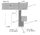
BRIEF DESCRIPTION OF THE DRAWINGS Figure 1 is a diagram showing the relationship of a blade of a cutting device to a ceramic log to be cut.
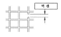
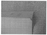
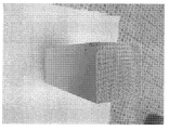
FIGS. 2A to 2F are diagrams showing defects that can occur in a ceramic log cutting process. FIG.
Fig. 3A is a view showing the orientation difference, the cutting direction and the blade portion below the center line of the cutting blade between the ceramic logs passing through the center line of the blade to be cut. Fig.
3B is a diagram showing a bar chart of the result of the third embodiment.
Figure 4a is a view of a cutting device of the present invention with a ceramic log disposed thereon.
Figure 4b is a view of a cutting blade of a device through a ceramic log.
5 is a chart showing the results of Comparative Example.
The description and illustrations presented herein are intended to enable one of ordinary skill in the art to understand its principles and applications. Those of ordinary skill in the art will understand that the invention may be embodied and applied in various forms such that it best suits the needs of a particular application. Certain embodiments of the invention as set forth are not intended to be exhaustive or to limit the invention. The scope of the invention should be determined with reference to the appended claims, along with the full scope of equivalents to which such claims are entitled. The disclosure of all data and references, including patent applications and public notices, is incorporated by reference for all purposes. Other combinations are also possible, as obtained from the following claims, which are incorporated herein by reference in their entireties.
The present invention provides a ceramic log having a first end and an opposite second end; Providing at least one cutting device comprising a dual blade cutting member; And removing the material by cutting at least the first end with a dual blade cutting member, wherein the first blade of the dual blade cutting member provides a finish surface and the second blade provides a surface finish of the scrap on the finish surface Remove a percentage.
In another aspect, the present invention provides a nesting fixture for fixing a ceramic log; The present invention relates to a ceramic log cutting apparatus comprising at least one cutting device comprising a motor and a dual blade cutting member; Wherein the first blade of the dual blade cutting member provides a finish surface and the off-set second blade removes a percentage of the scrap on the finish surface.
The invention also relates to the features described herein, for example: the ratio of scrap removed by the second blade is sufficient to prevent one or more defects adjacent the exit edge of the cutting of the ceramic log; The one or more defects adjacent the exit edge of the cut include areas of the missing ceramic material at the finish surface; One or more defects adjacent the exit edge of the cut include one or more chips having a depth of at least 1 mm; The second blade providing increased stiffness to the first blade; The leading edge of the cut surface of the second blade is positioned at a distance sufficient to remove a sufficient amount of scrap into the leading edge of the cut surface of the first blade to prevent one or more defects adjacent the exit edge of the cutting of the ceramic log Off-set; The second blade being off-set inside the leading edge of the cutting edge of the first blade by 2 mm or more; Wherein the first blade includes a first blade type and the off-set second blade includes a second blade type; The first blade type and the second blade type being the same; The first blade type being a grinding saw; The second blade type being a single-sided serrated blade; The serrated blades having a kerf in the range of 4 mm to 30 mm; Ceramic logs having a water content of less than 10%; Ceramic logs having a moisture content of less than 5%; Ceramic logs having a moisture content of less than 2.5%; Removing the material by cutting the second end of the at least one opposite piece with a dual blade cutting member; Simultaneously cutting the first end and the opposite second end with two double blade cutting members; The cutting device comprising a circular saw; Wherein the cutting device comprises a band saw; The cutting device comprising a reciprocating saw; Wherein the ceramic log comprises at least one honeycomb structure surrounded by any outer skin layer; One or more defects adjacent the exit edge of the cut include an outer skin layer and / or a honeycomb wall peel area from another honeycomb structure; The ceramic logs include unfiltered; And ceramic logs may be characterized by one or any combination of mullite, cordierite, SiC, or mixtures thereof.
The present invention is particularly directed to an improved method and apparatus for manufacturing a ceramic product (log) with a desired segment length for a relatively short process cycle time, while minimizing both defects at or near the exit edge of the cut.
Ceramic products
Ceramic products (and eventually ceramic bodies or logs) are generally produced by a multi-step process. Generally, the process begins by contacting one or more precursors to a ceramic structure, a ceramic precursor, optionally one or more binders, and one or more liquid carriers. In general, the next step is by many shaping processes, most commonly by extrusion, followed by cutting to near net dimensions (e.g., length, width, thickness) before the next process step , And the formation of the desired shape. The product is then typically dried to a point where the moisture content is in the range of about 0 to 10%. This is when the method / apparatus of the present invention can be used (however, the method / apparatus of the present invention may be used for further processed ceramic products). After the product has been cut to the "finished" length, it can then be further processed (e.g., plugged, calcined, mullitized, etc.). Additional details on this step are provided in the following paragraphs.
Ceramic precursors are generally reactants or components that form ceramic bodies or parts when exposed to certain conditions, such as those described in US 7,485,594; US 6,953,554; A porous mullite made by forming a mixture of a substance enhancing compound with at least one precursor compound having an element present in mullite (for example, clay, alumina, silica) as disclosed in US 4,948,766 and US 5,173,349, ≪ / RTI > composition. The property enhancing compound may be at least one selected from the group consisting of Mg, Ca, Fe, Na, K, Ce, Pr, Nd, Sm, Eu, Gd, Tb, Dy, Ho, Er, Tm, Yb, Lu, ≪ / RTI > may be a compound having an element selected from the group consisting of Further, the ceramic precursor may be at least one selected from the group consisting of silicon carbide, cordierite, aluminum titanate, alumina, zirconia, silicon nitride, aluminum nitrides, silicon oxynitride, silicon carbonitride, betasspodumin, strontium aluminum silicate, . Organic binders useful in the present invention include any known materials that shape wet ceramic green bodies. Preferably, the binder is an organic material that decomposes or burns at a temperature below the temperature at which the ceramic precursor reacts to form the ceramic body or part. Among the preferred binding agent a document incorporated by reference herein [Introduction to the Principles of Ceramic Processing , J. Reed, Wiley Interscience, 1988]. Particularly preferred binders are methylcellulose (e.g., METHOCEL A15LV methylcellulose, The Dow Chemical Co., Midland, MI). The liquid carrier includes any liquid that promotes the formation of a wettable ceramic mixture that can be stylized. Among the preferred liquid carrier (dispersant) Literature [Introduction to the Principles of Ceramic Processing , J. Reed, Wiley Interscience, 1988]. A particularly preferred liquid carrier is water. Mixtures useful for making wet ceramic green bodies can be made by any suitable method known in the art. Examples include ball milling, ribbon blending, vertical screw mixing, V-blending and attrition milling. The mixture may be prepared dry (i.e., without a liquid carrier) or wet. If the mixture is prepared without a liquid carrier, the liquid carrier is added later using any of the methods described in this paragraph.
The mixture of ceramic precursor, optional binder and liquid carrier may be shaped by any means known in the art. Examples include injection molding, extrusion, isobaric compression molding, slip casting, roll compression and tape casting. Each of which is a document incorporated by reference herein [Introduction to the Principles of Ceramic Processing , J. Reed, Chapters 20 and 21, Wiley Interscience, 1988). In a preferred embodiment, the mixture is shaped to approximate the net shape and size of the final desired ceramic body, e.g., a flow-through filter. Close to the net shape and size means that the size of the wet ceramic green body can be within about 10-15 vol% of the size of the final ceramic body, and preferably the size and shape is less than 5 vol% . In one preferred embodiment, the ceramic structure comprises a honeycomb structure and an outer skin layer. Preferably, the honeycomb structure is disposed on a plane perpendicular to the extrusion direction. The outer skin layer and the honeycomb structured wall typically have a thickness of about 250 to 600 micrometers, but a structure having a thickness that is greater or less than about 50% is also contemplated. In use, each channel formed is sealed at one end or the other end. In the plane, the channels are sealed in an alternating fashion. Preferably, the wet ceramic green body does not have any channels or channels that are clogged or sealed. In the practice of the present invention, porous ceramic honeycomb, as well as plugs (which may be the same or different ceramics as the honeycomb, but also may be honeycomb partition walls pinched together to simply block the channels May be any suitable ceramic or combination of ceramics.
In a preferred embodiment, the wet ceramic green body is shaped to be usable as a flow-through filter. At this stage of the process, the wet ceramic green body has two opposed faces that are substantially planar. The wet ceramic green body exhibits a matching cross-sectional shape for all the sides parallel to the two opposing sides. The cross-sectional shape may be any shape suitable for the purpose of use, may be irregular, or it may be of any known shape, for example, round oval or polygonal. The cross-sectional shape preferably represents a flat surface capable of supporting the ceramic body. Preferably, the cross-sectional shape is polygonal. In a preferred embodiment, the shape is rectangular or square. If the shape is irregular, the wet ceramic body must have at least one linear path or one flat surface so that it can be placed on a linear path or a carrier on the surface of the plane. The wet ceramic wastes have a plurality of walls formed extending from one opposed face to another opposed face. The walls form a plurality of flow paths extending from one opposed surface to the other opposed surface. Preferably, at this stage, all the flow paths are open to both opposing surfaces. This makes it possible to remove the liquid carrier more effectively. The wet ceramic green body is then conditioned to remove the liquid carrier, i. E. Conditions for drying the wet ceramic green body, preferably the moisture content is less than about 10%, more preferably less than about 5% And about 2.5% or less. A preferred drying method is described in PCT application Ser. No. 13 / 166,298, filed June 22, 2011, filed June 22, 2011, filed June 22, 2011 and filed on June 22, 2011, both of which are incorporated herein by reference. Quot; DRYING METHOD FOR CERAMIC GREENWARE ".
After removing the liquid carrier from the wet ceramic green body, the ceramic green body may be prepared for conversion to a ceramic body, wherein the process / apparatus of the present invention may be used by cutting the body (log) to a desired length (Although the present invention can be equally effective when curing or mulling ceramics further). After using the method / apparatus of the present invention disclosed herein, the ceramic scatters are exposed to conditions to burn the binder and form a ceramic structure. Processes for accomplishing this are well known in the art. The dried ceramic green body component is calcined by heating the dried ceramic green body component to a temperature at which the organic additive and binder are volatilized or burned out. The component is further heated to a temperature at which the ceramic particles are fused or sintered together or subsequently to produce new fine particles to be fused together. Such methods are described, for example, in US 4,329,162; 4,471,792; 4,001,028; 4,162,285; 3,899,326; 4,786,542; 4,837,943, and 5,538,681, all of which are incorporated herein by reference; All of which are incorporated herein by reference.
It is contemplated that the present invention is applicable to any porous particulate itself. Most preferably, it is also applicable to raw, debindered raw paper, and also to plasticized, which will melt or react later to form a stronger body, even if the particulates are molten.
flaw
It is contemplated that the "defects" associated with the present invention can be broadly defined as surface irregularities on or near the end face of the cleavage log. This surface irregularity can be on the wall of the honeycomb structure, on the outer skin layer, or both. Figures 2a-f show an illustrative example in which the " chip "of the outer skin layer was absent and / or part of the honeycomb wall was absent. In one embodiment, the defect can be defined as a problem in the downstream process of the part, for example, a surface irregularity that causes the honeycomb channel to be sealed. In a preferred embodiment, the defect may be defined as one or more chips at a depth of at least 1 mm (depth from the finish surface) at or near the exit edge of the cut (e.g., within about 25 mm).
cut device
(E. G., Length) of the ceramic body and more preferably wet (e. G., Containing less than about 10% by weight of the ceramic) ceramic raw material while maintaining or creating an acceptable surface finish on the part A cutting device and method are provided. It should also be noted that the cutting process must be relatively fast, e.g., the ceramic body is subjected to a desired length in less than about 2 minutes, and more preferably less than about 20 seconds, and preferably in excess of about 5 seconds Quot;) < / RTI > Also, preferably only one cutting path (for the end) should be used to achieve the desired length and surface finish. In one preferred embodiment, the scrap material removed from the cut end is sufficient to prevent one or more defects adjacent the exit edge of the cutting of the ceramic logs.
It is contemplated that the movement across the body to be cut is preferably in the range of about 10 to 40 cm / min. In the case of a circular saw configuration, the rotation of the blades may vary from less than about 500 rpm to as high as about 3000 rpm or more. In a preferred embodiment, the rotation is from about 750 to 2500 rpm and more preferably from about 1000 to 2000 rpm. In the case of a belt or a reciprocating saw, the linear motion of the blade is expressed in meters per minute (m / min). Which may range from as low as about 900 m / min to as high as about 2000 m / min. Preferably, the linear motion of the blade is from about 1500 m / min to about 1750 m / min, and more preferably from about 1600 m / min to 1700 m / min.
The cutting device may be included in a ceramic log cutter. The apparatus may include a nesting fixture that serves to secure the ceramic component. It may also include a power source (e.g., a motor) that serves to move the cutting device (s). It may also include one or more cutting devices, for example, a cutting device disposed at a distance from each other such that each device can cut the opposite edges of the ceramic component simultaneously or in close proximity.
Cutting devices can be configured in many different forms. Functionally, the device not only eliminates the amount of logs (e.g., scrap) but also provides a relatively defect free end face (e.g., less than one chip). The device may be in the form of a circular saw, band saw, or reciprocating saw. Whatever the shape of the cutting device, the device should be configured to have two or more cutting surfaces that are immediately adjacent (e.g., within about 10 mm) and in contact with each other.
The cutting device preferably comprises a dual blade cutting member in which one blade serves to directly cut the finishing surface of the log and the second blade serves to assist in the removal of the scrap material. The two blades may be adjacent to each other along one side (or may be spaced apart by about 10 mm) and preferably off-set along the cutting plane. The leading edge of the cut surface of the second blade may be offset off the leading edge of the cut surface of the first blade to a sufficient distance to remove a sufficient amount of scrap to prevent one or more defects adjacent the exit edge of the cutting of the ceramic log . In one preferred embodiment, the second blades are all off-set to within about 2.0 mm, more preferably at least about 5.0 mm, and most preferably at least about 12.5 mm into the leading edge of the cut surface of the first blade, Less than 50.0 mm, more preferably less than or equal to about 45 mm, and most preferably less than or equal to about 40.0 mm.
The blades may include the same or different blade types, as long as they provide the functionality discussed in this disclosure. In one embodiment, the blades are constructed of the same type of blades. In another embodiment, the blades are of two different types. Useful blade types include, for example, a grinding saw blade and a serrated saw blade. A grinding saw blade is similar to a thin grinding wheel, and a serrated saw blade is a blade having a cutting edge with a number of small contacts with the material to be cut.
In a preferred embodiment, the blades are of a different type, wherein the first blade is an abrasive blade and the second blade is a serrated blade. More specifically, the grinding blade includes a diamond grit blade, the serrated blade is a carbide tipped blade, and more specifically a single-sided blade.
In one preferred diamond grit blade embodiment, the blades may include grit grades that can range from as low as 40/60 to as high as 200/220, and may also be performed as needed. Functionally, the grit value should be adequate to truncate the log without creating excessive defects. The higher the grit value (for example, deleting the finer openings), the greater the likelihood of defect-free cutting, but there is a greater likelihood that the blade will become more clogged and more often washed ("trimmed" It is believed to be higher. It is believed that there is a relationship between the water content of the log and the limit on how high the grit value can be used. In one preferred embodiment, a log having a grit value of no greater than about 60/80 with a moisture content below about 10% moisture content, more preferably no more than about 5% by weight grit content of no more than about 100/120, , And most preferably not more than about 200/220 grit, to a log having a water content below about 2.5 weight percent.
In one preferred serrated blade embodiment, the cutting member has a cuff that is at least about 2 mm, more preferably at least about 4 mm, and most preferably at least about 7 mm. It is also preferred that the cuff is about 50 mm or less, more preferably about 40 mm or less, and most preferably about 30 mm or less.
Preferably, the blades provide complementary structural reinforcement or increased structural stiffness, especially when the two blades are adjacent to one another along one side. The combined blades provide sufficient stiffness to reduce or eliminate any warpage that can lead to defects. In a preferred embodiment, when the two blades are together, they are at least 100% stiffer than when the blades are not together. This can serve to enable the blade to operate while preventing excessive motion or bending that can cause surface defects on the ceramic component.
In a preferred embodiment, the device is a circular saw, wherein the device comprises a dual blade rotating in the same direction with respect to the central axis. It is preferred that the dual blades are adjacent to each other in one plane and have a radially offset (first large blade and second small blade) cut surface. It is believed that the diameter of the blade should be greater than the cross length of the ceramic body to be cut. In one preferred embodiment, the blade diameter is large enough to sever the log in one pass. Preferably, the blade diameter is at least about 240% greater than the cross-sectional length (e.g., the area to be cut) of the ceramic body, more preferably about 300 or greater, and most preferably about 385 or greater; And at most about 600% greater, more preferably at most about 500 greater, and most preferably at most about 420 greater.
Further, it is preferable that the entire cross-sectional length of the ceramic body is properly positioned within the diameter of the blade. That is, the center of the ceramic body must be adjacent to the rotation axis of the circular blade. Preferably, the central axis of the ceramic body is at least about a half of the radius of the first blade, more preferably about 1/3 or less, and most preferably about 1/4 or less of the radius of the first blade that is equal to or larger than the central axis of the circular blade laterally) off-set. An exemplary embodiment (Example 3) is provided below. Fig. 3A shows the rotation axis 400 (the center of the blade in the cutting direction) with respect to the two orientations of the ceramic body relative to the blade.
Preferably, the cutting method given in the above detailed description and in the following examples comprises at least: providing a ceramic log having a first end and an opposite second end; Providing at least one cutting device comprising a dual blade cutting member; And removing the material by cutting at least the first end with the dual blade cutting member, wherein the first blade of the double blade cutting member provides a finish surface and the second blade provides a percentage of the scrap on the finish surface Remove.
Preferably, the proportion of scrap removed with the second blade is sufficient to prevent the defects discussed in the present application. As the blade moves across the log and cuts, the second blade removes a percentage of the scrap from above the first blade. This eliminates the clumping of the scrap, thereby reducing the potential adverse effect that the presence of scrap may have on the log wall (inner or outer wall) before the occurrence of the defect and before the first blade approaches (or reaches) the exit edge of the cut . In a preferred embodiment, the second blade is at least about 50%, more preferably at least about 60% of the scrap, and most preferably at least about 60% of the total scrap before the first blade comes At least about 70%, and at most about 95%, more preferably at most about 90%, and most preferably at most 85 of total scrap.
There is a relationship between the cuff of the serrated blade and the cutting position that occurs below the end of the log. The distance "D" is the distance from the end of the uncut log to the finished cut surface. The "D" is small enough so that the cutting member effectively removes the scrap and prevents defects in the log resulting from the cutting, but is preferably large enough to require only one cutting per face for the process. Preferably, "D" is about 0.5 to about 3.0 times, more preferably about 0.75 to 2.0 times, and most preferably about 1.0 to 1.5 times the cuff of the second blade.
Exemplary embodiments of the present invention
The following examples are provided to illustrate the invention, but are not intended to limit its scope. It is contemplated that any dimension information used in this embodiment should not be construed as limiting and ceramic components and cutting devices may be significantly smaller or larger.
Example 1: circular saw (200)
As an exemplary embodiment, a circular saw-type ceramic
In this embodiment, the double
The
Example 2: band saw / reciprocating saw (500)
As another exemplary embodiment, a band saw / reciprocating saw type ceramic
Example 3: Circular saw (600)
In an exemplary embodiment, two circular saw-type ceramic log cutting methods are shown. In the first configuration YL11, the

Comparative Example
Embodiments are implemented between a

Unless otherwise stated, the dimensions and geometries of the various structures shown herein are not intended to limit the invention, and other dimensions and geometries are possible. The plurality of structural components may be provided in a single, unified structure. Alternatively, a single unified structure may be divided into separate components. Also, while the features of the invention have been described in just one of the exemplary embodiments, such features may be combined with one or more other features of other embodiments for any given application. It will also be appreciated that the fabrication and manipulation of the inherent constructions herein from above also constitute a method consistent with the present invention.
Any numerical value recited in this application includes any value that increments by one unit from a lower limit value to an upper limit value, provided that there is at least two units between any lower limit value and any upper limit value. By way of example, when the value of a component or the value of a process variable such as temperature, pressure, time, etc. is mentioned as being, for example, 1 to 90, preferably 20 to 80, more preferably 30 to 70 , Such as 15 to 85, 22 to 68, 43 to 51, 30 to 32, etc. are intended to be explicitly recited herein. 1 for values less than 1 The unit is considered to be suitably 0.0001, 0.001, 0.01, or 0.1. It is to be understood that this is merely an example of what is specifically intended and that the combination of all possible numerical values between the lower and the upper limit values listed is explicitly referred to in the present application in a similar manner. The term "consisting essentially of " for describing a combination may include other elements, elements, components, or steps that do not materially affect the identified element, element, component or step, . Also, the use of the term "comprising or " to describe a combination of elements, elements, components or steps herein is intended to encompass embodiments comprised essentially of elements, elements, components or steps . A plurality of elements, elements, components, or steps may be provided in a single integrated element, element, component, or step. As an alternative, a single integrated element, element, component, or step may be divided into separate multiple elements, elements, components, or steps. Quot; or " one "to describe an element, element, element, or step is not intended to exclude additional elements, elements, components, or steps. Unless otherwise stated, all ranges include all numbers between both endpoints and endpoints. The use of "about" or "about " in relation to a range applies to both ends of the range. Thus, "about 20 to 30" is intended to encompass "about 20 to about 30 ", including at least the specified endpoint.
Claims (20)
At least one cutting device comprising a motor and a dual blade cutting member;
Lt; / RTI >
Wherein the first blade of the dual blade cutting member provides a finish surface and the second off-set blade removes a percentage of the scrap on the finish surface,
Ceramic log cutting equipment.
Providing at least one cutting device according to any one of claims 1 to 14;
Removing the material by cutting at least the first end with the double blade cutting member
Wherein the first blade of the dual blade cutting member provides a finish surface and the second blade removes a percentage of the scrap on the finish surface.
Applications Claiming Priority (3)
| Application Number | Priority Date | Filing Date | Title |
|---|---|---|---|
| US201161577312P | 2011-12-19 | 2011-12-19 | |
| US61/577,312 | 2011-12-19 | ||
| PCT/US2012/069714 WO2013096113A1 (en) | 2011-12-19 | 2012-12-14 | Improved method and apparatus for preparing ceramic body segments |
Publications (1)
| Publication Number | Publication Date |
|---|---|
| KR20140104035A true KR20140104035A (en) | 2014-08-27 |
Family
ID=47559659
Family Applications (1)
| Application Number | Title | Priority Date | Filing Date |
|---|---|---|---|
| KR1020147019775A KR20140104035A (en) | 2011-12-19 | 2012-12-14 | Improved method and apparatus for preparing ceramic body segments |
Country Status (6)
| Country | Link |
|---|---|
| US (1) | US9987766B2 (en) |
| JP (1) | JP6196234B2 (en) |
| KR (1) | KR20140104035A (en) |
| CN (1) | CN104023926B (en) |
| DE (1) | DE112012005343T5 (en) |
| WO (1) | WO2013096113A1 (en) |
Families Citing this family (2)
| Publication number | Priority date | Publication date | Assignee | Title |
|---|---|---|---|---|
| JP5749691B2 (en) * | 2012-06-27 | 2015-07-15 | 日本碍子株式会社 | Method for manufacturing ceramic honeycomb structure |
| CN113954228B (en) * | 2021-10-26 | 2023-08-18 | 山东工业陶瓷研究设计院有限公司 | SOFC support body processing system and application method thereof |
Family Cites Families (28)
| Publication number | Priority date | Publication date | Assignee | Title |
|---|---|---|---|---|
| US3899326A (en) | 1973-03-30 | 1975-08-12 | Corning Glass Works | Method of making monolithic honeycombed structures |
| US4001028A (en) | 1974-05-28 | 1977-01-04 | Corning Glass Works | Method of preparing crack-free monolithic polycrystalline cordierite substrates |
| JPS6034510B2 (en) | 1976-06-10 | 1985-08-09 | 日本碍子株式会社 | Extrusion manufacturing method of ceramic honeycomb structure |
| US4329162A (en) | 1980-07-03 | 1982-05-11 | Corning Glass Works | Diesel particulate trap |
| CH650030A5 (en) | 1981-11-24 | 1985-06-28 | Lpw Reinigungstechnik Gmbh | DEVICE FOR SOLVENT TREATMENT OF PARTICULAR METAL TREATMENT. |
| US4786542A (en) | 1986-02-20 | 1988-11-22 | Ngk Insulators, Ltd. | Setters and firing of ceramic honeycomb structural bodies by using the same |
| JPH061150B2 (en) | 1986-12-27 | 1994-01-05 | 日本碍子株式会社 | Dielectric drying method of honeycomb structure |
| US4948766A (en) | 1988-08-05 | 1990-08-14 | The United States Of America As Represented By The Secretary Of The Navy | Rigid mullite=whisker felt and method of preparation |
| CA2020453A1 (en) | 1989-07-28 | 1991-01-29 | Bulent O. Yavuz | Thermal shock and creep resistant porous mullite articles |
| JP3005068B2 (en) * | 1991-03-27 | 2000-01-31 | 日本碍子株式会社 | Ceramic pipe cutting apparatus and ceramic pipe cutting method using the same |
| US5314650A (en) * | 1993-02-23 | 1994-05-24 | Corning Incorporated | Method for extruding honeycombs |
| US5538681A (en) | 1994-09-12 | 1996-07-23 | Corning Incorporated | Drying process to produce crack-free bodies |
| US6669751B1 (en) | 1999-09-29 | 2003-12-30 | Ibiden Co., Ltd. | Honeycomb filter and ceramic filter assembly |
| DE60037205T2 (en) | 1999-12-23 | 2008-10-02 | Dow Global Technologies, Inc., Midland | CATALYTIC DEVICES |
| JP4106918B2 (en) * | 2002-01-29 | 2008-06-25 | 株式会社デンソー | Cutting method of honeycomb molded body |
| PL1685926T3 (en) | 2003-11-19 | 2016-03-31 | Ngk Insulators Ltd | Grinding method |
| US7485594B2 (en) | 2005-10-03 | 2009-02-03 | Dow Global Technologies, Inc. | Porous mullite bodies and methods of forming them |
| JP4692230B2 (en) | 2005-11-01 | 2011-06-01 | 株式会社デンソー | Method for manufacturing ceramic honeycomb structure |
| JP2007144922A (en) * | 2005-11-30 | 2007-06-14 | Hitachi Metals Ltd | Manufacturing method of ceramic honeycomb structure |
| WO2007116529A1 (en) * | 2006-04-11 | 2007-10-18 | Ibiden Co., Ltd. | Molded item cutting apparatus, method of cutting ceramic molded item, and process for producing honeycomb structure |
| CN101484288A (en) * | 2006-09-28 | 2009-07-15 | 日立金属株式会社 | Method and apparatus for manufacturing ceramic honeycomb structure |
| US7909904B2 (en) | 2007-03-19 | 2011-03-22 | Corning Incorporated | Face finished honeycomb structures and methods of manufacturing same |
| EP2174921B1 (en) * | 2007-07-26 | 2015-04-08 | NGK Insulators, Ltd. | Bonding material for honeycomb structure and honeycomb structure utilizing the material |
| US8701646B2 (en) * | 2008-02-29 | 2014-04-22 | Corning Incorporated | System and method for cutting ceramic ware |
| CN101579887B (en) * | 2009-06-17 | 2011-09-07 | 江苏高淳陶瓷股份有限公司 | Honeycomb ceramic dry green body dual-blade cutting machine |
| EP2585782A1 (en) | 2010-06-25 | 2013-05-01 | Dow Global Technologies LLC | Drying method for ceramic green ware |
| EP2607336B1 (en) * | 2010-08-19 | 2015-06-24 | Hitachi Metals, Ltd. | Manufacturing method for ceramic honeycomb structure |
| CN102241060B (en) * | 2011-07-05 | 2015-11-18 | 南京柯瑞特种陶瓷股份限公司 | A kind of honeycomb ceramic dry green body dual-blade Continuous Cutting Machine |
-
2012
- 2012-12-14 WO PCT/US2012/069714 patent/WO2013096113A1/en active Application Filing
- 2012-12-14 KR KR1020147019775A patent/KR20140104035A/en active IP Right Grant
- 2012-12-14 DE DE112012005343.5T patent/DE112012005343T5/en not_active Withdrawn
- 2012-12-14 JP JP2014547480A patent/JP6196234B2/en not_active Expired - Fee Related
- 2012-12-14 CN CN201280062661.6A patent/CN104023926B/en not_active Expired - Fee Related
- 2012-12-14 US US14/362,478 patent/US9987766B2/en not_active Expired - Fee Related
Also Published As
| Publication number | Publication date |
|---|---|
| CN104023926B (en) | 2016-10-19 |
| DE112012005343T5 (en) | 2014-09-04 |
| WO2013096113A1 (en) | 2013-06-27 |
| US9987766B2 (en) | 2018-06-05 |
| CN104023926A (en) | 2014-09-03 |
| US20140326229A1 (en) | 2014-11-06 |
| JP6196234B2 (en) | 2017-09-13 |
| JP2015501744A (en) | 2015-01-19 |
Similar Documents
| Publication | Publication Date | Title |
|---|---|---|
| EP1880817A1 (en) | Method for cutting honeycomb structure | |
| EP1992394B1 (en) | Honeycomb filter | |
| KR101113619B1 (en) | Honeycomb structure, process for producing honeycomb structure, honeycomb filter and process for producing honeycomb filter | |
| US7309277B2 (en) | Method of manufacturing honeycomb structural body | |
| EP2366444B1 (en) | Honeycomb structure | |
| CN101274293A (en) | Honeycomb structure and exhaust gas treatment device | |
| JP2004321851A (en) | Honeycomb structure, its production method, mouth piece for molding and discharge fluid cleaning system | |
| JP5255626B2 (en) | Method and apparatus for manufacturing honeycomb structure with chamfered outer skin and honeycomb structure | |
| JP4908951B2 (en) | Manufacturing method of honeycomb formed body and grinding apparatus thereof | |
| KR20080093860A (en) | Catalyst supporting honeycomb and method of manufacturing the same | |
| KR102013760B1 (en) | Ceramic honeycomb body fabrication method | |
| EP2108436A1 (en) | Honeycomb structure and method for manufacturing the same | |
| JP2009255041A (en) | Method for manufacturing honeycomb structure | |
| JP2008302355A (en) | Honeycomb filter | |
| JP4632125B2 (en) | Method for manufacturing ceramic honeycomb structure | |
| KR20140104035A (en) | Improved method and apparatus for preparing ceramic body segments | |
| JP2017159197A (en) | Honeycomb structure | |
| JP2007144922A (en) | Manufacturing method of ceramic honeycomb structure | |
| JP3953245B2 (en) | Manufacturing method of honeycomb structure | |
| JP2015501744A5 (en) | ||
| EP2221099B1 (en) | Honeycomb structure | |
| JP5667346B2 (en) | Manufacturing method of honeycomb structure | |
| JP5390171B2 (en) | Manufacturing method of honeycomb structure | |
| JP6635847B2 (en) | Method for cutting honeycomb formed body and method for manufacturing honeycomb structure | |
| JP2020157260A (en) | Method for producing honeycomb structure |
Legal Events
| Date | Code | Title | Description |
|---|---|---|---|
| A201 | Request for examination | ||
| E902 | Notification of reason for refusal | ||
| E701 | Decision to grant or registration of patent right |