KR20140093943A - Implants with a connectable insert and related systems and methods - Google Patents
Implants with a connectable insert and related systems and methods Download PDFInfo
- Publication number
- KR20140093943A KR20140093943A KR1020147012288A KR20147012288A KR20140093943A KR 20140093943 A KR20140093943 A KR 20140093943A KR 1020147012288 A KR1020147012288 A KR 1020147012288A KR 20147012288 A KR20147012288 A KR 20147012288A KR 20140093943 A KR20140093943 A KR 20140093943A
- Authority
- KR
- South Korea
- Prior art keywords
- cavity
- insert
- threadable
- spacer
- trunk
- Prior art date
Links
Images


Classifications
-
- A—HUMAN NECESSITIES
- A61—MEDICAL OR VETERINARY SCIENCE; HYGIENE
- A61F—FILTERS IMPLANTABLE INTO BLOOD VESSELS; PROSTHESES; DEVICES PROVIDING PATENCY TO, OR PREVENTING COLLAPSING OF, TUBULAR STRUCTURES OF THE BODY, e.g. STENTS; ORTHOPAEDIC, NURSING OR CONTRACEPTIVE DEVICES; FOMENTATION; TREATMENT OR PROTECTION OF EYES OR EARS; BANDAGES, DRESSINGS OR ABSORBENT PADS; FIRST-AID KITS
- A61F2/00—Filters implantable into blood vessels; Prostheses, i.e. artificial substitutes or replacements for parts of the body; Appliances for connecting them with the body; Devices providing patency to, or preventing collapsing of, tubular structures of the body, e.g. stents
- A61F2/02—Prostheses implantable into the body
- A61F2/30—Joints
- A61F2/3094—Designing or manufacturing processes
-
- A—HUMAN NECESSITIES
- A61—MEDICAL OR VETERINARY SCIENCE; HYGIENE
- A61F—FILTERS IMPLANTABLE INTO BLOOD VESSELS; PROSTHESES; DEVICES PROVIDING PATENCY TO, OR PREVENTING COLLAPSING OF, TUBULAR STRUCTURES OF THE BODY, e.g. STENTS; ORTHOPAEDIC, NURSING OR CONTRACEPTIVE DEVICES; FOMENTATION; TREATMENT OR PROTECTION OF EYES OR EARS; BANDAGES, DRESSINGS OR ABSORBENT PADS; FIRST-AID KITS
- A61F2/00—Filters implantable into blood vessels; Prostheses, i.e. artificial substitutes or replacements for parts of the body; Appliances for connecting them with the body; Devices providing patency to, or preventing collapsing of, tubular structures of the body, e.g. stents
- A61F2/02—Prostheses implantable into the body
- A61F2/30—Joints
- A61F2/44—Joints for the spine, e.g. vertebrae, spinal discs
- A61F2/4455—Joints for the spine, e.g. vertebrae, spinal discs for the fusion of spinal bodies, e.g. intervertebral fusion of adjacent spinal bodies, e.g. fusion cages
- A61F2/4465—Joints for the spine, e.g. vertebrae, spinal discs for the fusion of spinal bodies, e.g. intervertebral fusion of adjacent spinal bodies, e.g. fusion cages having a circular or kidney shaped cross-section substantially perpendicular to the axis of the spine
-
- A—HUMAN NECESSITIES
- A61—MEDICAL OR VETERINARY SCIENCE; HYGIENE
- A61F—FILTERS IMPLANTABLE INTO BLOOD VESSELS; PROSTHESES; DEVICES PROVIDING PATENCY TO, OR PREVENTING COLLAPSING OF, TUBULAR STRUCTURES OF THE BODY, e.g. STENTS; ORTHOPAEDIC, NURSING OR CONTRACEPTIVE DEVICES; FOMENTATION; TREATMENT OR PROTECTION OF EYES OR EARS; BANDAGES, DRESSINGS OR ABSORBENT PADS; FIRST-AID KITS
- A61F2/00—Filters implantable into blood vessels; Prostheses, i.e. artificial substitutes or replacements for parts of the body; Appliances for connecting them with the body; Devices providing patency to, or preventing collapsing of, tubular structures of the body, e.g. stents
- A61F2/02—Prostheses implantable into the body
- A61F2/30—Joints
- A61F2/44—Joints for the spine, e.g. vertebrae, spinal discs
- A61F2/4455—Joints for the spine, e.g. vertebrae, spinal discs for the fusion of spinal bodies, e.g. intervertebral fusion of adjacent spinal bodies, e.g. fusion cages
- A61F2/447—Joints for the spine, e.g. vertebrae, spinal discs for the fusion of spinal bodies, e.g. intervertebral fusion of adjacent spinal bodies, e.g. fusion cages substantially parallelepipedal, e.g. having a rectangular or trapezoidal cross-section
-
- A—HUMAN NECESSITIES
- A61—MEDICAL OR VETERINARY SCIENCE; HYGIENE
- A61F—FILTERS IMPLANTABLE INTO BLOOD VESSELS; PROSTHESES; DEVICES PROVIDING PATENCY TO, OR PREVENTING COLLAPSING OF, TUBULAR STRUCTURES OF THE BODY, e.g. STENTS; ORTHOPAEDIC, NURSING OR CONTRACEPTIVE DEVICES; FOMENTATION; TREATMENT OR PROTECTION OF EYES OR EARS; BANDAGES, DRESSINGS OR ABSORBENT PADS; FIRST-AID KITS
- A61F2/00—Filters implantable into blood vessels; Prostheses, i.e. artificial substitutes or replacements for parts of the body; Appliances for connecting them with the body; Devices providing patency to, or preventing collapsing of, tubular structures of the body, e.g. stents
- A61F2/02—Prostheses implantable into the body
- A61F2/30—Joints
- A61F2/46—Special tools or methods for implanting or extracting artificial joints, accessories, bone grafts or substitutes, or particular adaptations therefor
- A61F2/4603—Special tools or methods for implanting or extracting artificial joints, accessories, bone grafts or substitutes, or particular adaptations therefor for insertion or extraction of endoprosthetic joints or of accessories thereof
- A61F2/4611—Special tools or methods for implanting or extracting artificial joints, accessories, bone grafts or substitutes, or particular adaptations therefor for insertion or extraction of endoprosthetic joints or of accessories thereof of spinal prostheses
-
- A—HUMAN NECESSITIES
- A61—MEDICAL OR VETERINARY SCIENCE; HYGIENE
- A61F—FILTERS IMPLANTABLE INTO BLOOD VESSELS; PROSTHESES; DEVICES PROVIDING PATENCY TO, OR PREVENTING COLLAPSING OF, TUBULAR STRUCTURES OF THE BODY, e.g. STENTS; ORTHOPAEDIC, NURSING OR CONTRACEPTIVE DEVICES; FOMENTATION; TREATMENT OR PROTECTION OF EYES OR EARS; BANDAGES, DRESSINGS OR ABSORBENT PADS; FIRST-AID KITS
- A61F2/00—Filters implantable into blood vessels; Prostheses, i.e. artificial substitutes or replacements for parts of the body; Appliances for connecting them with the body; Devices providing patency to, or preventing collapsing of, tubular structures of the body, e.g. stents
- A61F2/02—Prostheses implantable into the body
- A61F2/28—Bones
- A61F2002/2817—Bone stimulation by chemical reactions or by osteogenic or biological products for enhancing ossification, e.g. by bone morphogenetic or morphogenic proteins [BMP] or by transforming growth factors [TGF]
-
- A—HUMAN NECESSITIES
- A61—MEDICAL OR VETERINARY SCIENCE; HYGIENE
- A61F—FILTERS IMPLANTABLE INTO BLOOD VESSELS; PROSTHESES; DEVICES PROVIDING PATENCY TO, OR PREVENTING COLLAPSING OF, TUBULAR STRUCTURES OF THE BODY, e.g. STENTS; ORTHOPAEDIC, NURSING OR CONTRACEPTIVE DEVICES; FOMENTATION; TREATMENT OR PROTECTION OF EYES OR EARS; BANDAGES, DRESSINGS OR ABSORBENT PADS; FIRST-AID KITS
- A61F2/00—Filters implantable into blood vessels; Prostheses, i.e. artificial substitutes or replacements for parts of the body; Appliances for connecting them with the body; Devices providing patency to, or preventing collapsing of, tubular structures of the body, e.g. stents
- A61F2/02—Prostheses implantable into the body
- A61F2/28—Bones
- A61F2002/2835—Bone graft implants for filling a bony defect or an endoprosthesis cavity, e.g. by synthetic material or biological material
-
- A—HUMAN NECESSITIES
- A61—MEDICAL OR VETERINARY SCIENCE; HYGIENE
- A61F—FILTERS IMPLANTABLE INTO BLOOD VESSELS; PROSTHESES; DEVICES PROVIDING PATENCY TO, OR PREVENTING COLLAPSING OF, TUBULAR STRUCTURES OF THE BODY, e.g. STENTS; ORTHOPAEDIC, NURSING OR CONTRACEPTIVE DEVICES; FOMENTATION; TREATMENT OR PROTECTION OF EYES OR EARS; BANDAGES, DRESSINGS OR ABSORBENT PADS; FIRST-AID KITS
- A61F2/00—Filters implantable into blood vessels; Prostheses, i.e. artificial substitutes or replacements for parts of the body; Appliances for connecting them with the body; Devices providing patency to, or preventing collapsing of, tubular structures of the body, e.g. stents
- A61F2/02—Prostheses implantable into the body
- A61F2/30—Joints
- A61F2002/30001—Additional features of subject-matter classified in A61F2/28, A61F2/30 and subgroups thereof
- A61F2002/30108—Shapes
- A61F2002/30199—Three-dimensional shapes
- A61F2002/30299—Three-dimensional shapes umbrella-shaped or mushroom-shaped
-
- A—HUMAN NECESSITIES
- A61—MEDICAL OR VETERINARY SCIENCE; HYGIENE
- A61F—FILTERS IMPLANTABLE INTO BLOOD VESSELS; PROSTHESES; DEVICES PROVIDING PATENCY TO, OR PREVENTING COLLAPSING OF, TUBULAR STRUCTURES OF THE BODY, e.g. STENTS; ORTHOPAEDIC, NURSING OR CONTRACEPTIVE DEVICES; FOMENTATION; TREATMENT OR PROTECTION OF EYES OR EARS; BANDAGES, DRESSINGS OR ABSORBENT PADS; FIRST-AID KITS
- A61F2/00—Filters implantable into blood vessels; Prostheses, i.e. artificial substitutes or replacements for parts of the body; Appliances for connecting them with the body; Devices providing patency to, or preventing collapsing of, tubular structures of the body, e.g. stents
- A61F2/02—Prostheses implantable into the body
- A61F2/30—Joints
- A61F2002/30001—Additional features of subject-matter classified in A61F2/28, A61F2/30 and subgroups thereof
- A61F2002/30316—The prosthesis having different structural features at different locations within the same prosthesis; Connections between prosthetic parts; Special structural features of bone or joint prostheses not otherwise provided for
- A61F2002/30329—Connections or couplings between prosthetic parts, e.g. between modular parts; Connecting elements
- A61F2002/30331—Connections or couplings between prosthetic parts, e.g. between modular parts; Connecting elements made by longitudinally pushing a protrusion into a complementarily-shaped recess, e.g. held by friction fit
- A61F2002/30362—Connections or couplings between prosthetic parts, e.g. between modular parts; Connecting elements made by longitudinally pushing a protrusion into a complementarily-shaped recess, e.g. held by friction fit with possibility of relative movement between the protrusion and the recess
- A61F2002/30375—Connections or couplings between prosthetic parts, e.g. between modular parts; Connecting elements made by longitudinally pushing a protrusion into a complementarily-shaped recess, e.g. held by friction fit with possibility of relative movement between the protrusion and the recess with an intermediate bushing or sleeve between the moving parts
-
- A—HUMAN NECESSITIES
- A61—MEDICAL OR VETERINARY SCIENCE; HYGIENE
- A61F—FILTERS IMPLANTABLE INTO BLOOD VESSELS; PROSTHESES; DEVICES PROVIDING PATENCY TO, OR PREVENTING COLLAPSING OF, TUBULAR STRUCTURES OF THE BODY, e.g. STENTS; ORTHOPAEDIC, NURSING OR CONTRACEPTIVE DEVICES; FOMENTATION; TREATMENT OR PROTECTION OF EYES OR EARS; BANDAGES, DRESSINGS OR ABSORBENT PADS; FIRST-AID KITS
- A61F2/00—Filters implantable into blood vessels; Prostheses, i.e. artificial substitutes or replacements for parts of the body; Appliances for connecting them with the body; Devices providing patency to, or preventing collapsing of, tubular structures of the body, e.g. stents
- A61F2/02—Prostheses implantable into the body
- A61F2/30—Joints
- A61F2002/30001—Additional features of subject-matter classified in A61F2/28, A61F2/30 and subgroups thereof
- A61F2002/30316—The prosthesis having different structural features at different locations within the same prosthesis; Connections between prosthetic parts; Special structural features of bone or joint prostheses not otherwise provided for
- A61F2002/30329—Connections or couplings between prosthetic parts, e.g. between modular parts; Connecting elements
- A61F2002/30433—Connections or couplings between prosthetic parts, e.g. between modular parts; Connecting elements using additional screws, bolts, dowels, rivets or washers e.g. connecting screws
-
- A—HUMAN NECESSITIES
- A61—MEDICAL OR VETERINARY SCIENCE; HYGIENE
- A61F—FILTERS IMPLANTABLE INTO BLOOD VESSELS; PROSTHESES; DEVICES PROVIDING PATENCY TO, OR PREVENTING COLLAPSING OF, TUBULAR STRUCTURES OF THE BODY, e.g. STENTS; ORTHOPAEDIC, NURSING OR CONTRACEPTIVE DEVICES; FOMENTATION; TREATMENT OR PROTECTION OF EYES OR EARS; BANDAGES, DRESSINGS OR ABSORBENT PADS; FIRST-AID KITS
- A61F2/00—Filters implantable into blood vessels; Prostheses, i.e. artificial substitutes or replacements for parts of the body; Appliances for connecting them with the body; Devices providing patency to, or preventing collapsing of, tubular structures of the body, e.g. stents
- A61F2/02—Prostheses implantable into the body
- A61F2/30—Joints
- A61F2002/30001—Additional features of subject-matter classified in A61F2/28, A61F2/30 and subgroups thereof
- A61F2002/30316—The prosthesis having different structural features at different locations within the same prosthesis; Connections between prosthetic parts; Special structural features of bone or joint prostheses not otherwise provided for
- A61F2002/30329—Connections or couplings between prosthetic parts, e.g. between modular parts; Connecting elements
- A61F2002/30448—Connections or couplings between prosthetic parts, e.g. between modular parts; Connecting elements using adhesives
-
- A—HUMAN NECESSITIES
- A61—MEDICAL OR VETERINARY SCIENCE; HYGIENE
- A61F—FILTERS IMPLANTABLE INTO BLOOD VESSELS; PROSTHESES; DEVICES PROVIDING PATENCY TO, OR PREVENTING COLLAPSING OF, TUBULAR STRUCTURES OF THE BODY, e.g. STENTS; ORTHOPAEDIC, NURSING OR CONTRACEPTIVE DEVICES; FOMENTATION; TREATMENT OR PROTECTION OF EYES OR EARS; BANDAGES, DRESSINGS OR ABSORBENT PADS; FIRST-AID KITS
- A61F2/00—Filters implantable into blood vessels; Prostheses, i.e. artificial substitutes or replacements for parts of the body; Appliances for connecting them with the body; Devices providing patency to, or preventing collapsing of, tubular structures of the body, e.g. stents
- A61F2/02—Prostheses implantable into the body
- A61F2/30—Joints
- A61F2002/30001—Additional features of subject-matter classified in A61F2/28, A61F2/30 and subgroups thereof
- A61F2002/30316—The prosthesis having different structural features at different locations within the same prosthesis; Connections between prosthetic parts; Special structural features of bone or joint prostheses not otherwise provided for
- A61F2002/30535—Special structural features of bone or joint prostheses not otherwise provided for
- A61F2002/30593—Special structural features of bone or joint prostheses not otherwise provided for hollow
-
- A—HUMAN NECESSITIES
- A61—MEDICAL OR VETERINARY SCIENCE; HYGIENE
- A61F—FILTERS IMPLANTABLE INTO BLOOD VESSELS; PROSTHESES; DEVICES PROVIDING PATENCY TO, OR PREVENTING COLLAPSING OF, TUBULAR STRUCTURES OF THE BODY, e.g. STENTS; ORTHOPAEDIC, NURSING OR CONTRACEPTIVE DEVICES; FOMENTATION; TREATMENT OR PROTECTION OF EYES OR EARS; BANDAGES, DRESSINGS OR ABSORBENT PADS; FIRST-AID KITS
- A61F2/00—Filters implantable into blood vessels; Prostheses, i.e. artificial substitutes or replacements for parts of the body; Appliances for connecting them with the body; Devices providing patency to, or preventing collapsing of, tubular structures of the body, e.g. stents
- A61F2/02—Prostheses implantable into the body
- A61F2/30—Joints
- A61F2002/30001—Additional features of subject-matter classified in A61F2/28, A61F2/30 and subgroups thereof
- A61F2002/30667—Features concerning an interaction with the environment or a particular use of the prosthesis
- A61F2002/30693—Air venting means
-
- A—HUMAN NECESSITIES
- A61—MEDICAL OR VETERINARY SCIENCE; HYGIENE
- A61F—FILTERS IMPLANTABLE INTO BLOOD VESSELS; PROSTHESES; DEVICES PROVIDING PATENCY TO, OR PREVENTING COLLAPSING OF, TUBULAR STRUCTURES OF THE BODY, e.g. STENTS; ORTHOPAEDIC, NURSING OR CONTRACEPTIVE DEVICES; FOMENTATION; TREATMENT OR PROTECTION OF EYES OR EARS; BANDAGES, DRESSINGS OR ABSORBENT PADS; FIRST-AID KITS
- A61F2/00—Filters implantable into blood vessels; Prostheses, i.e. artificial substitutes or replacements for parts of the body; Appliances for connecting them with the body; Devices providing patency to, or preventing collapsing of, tubular structures of the body, e.g. stents
- A61F2/02—Prostheses implantable into the body
- A61F2/30—Joints
- A61F2/30767—Special external or bone-contacting surface, e.g. coating for improving bone ingrowth
- A61F2/30771—Special external or bone-contacting surface, e.g. coating for improving bone ingrowth applied in original prostheses, e.g. holes or grooves
- A61F2002/30772—Apertures or holes, e.g. of circular cross section
- A61F2002/30777—Oblong apertures
- A61F2002/30779—Oblong apertures arcuate
-
- A—HUMAN NECESSITIES
- A61—MEDICAL OR VETERINARY SCIENCE; HYGIENE
- A61F—FILTERS IMPLANTABLE INTO BLOOD VESSELS; PROSTHESES; DEVICES PROVIDING PATENCY TO, OR PREVENTING COLLAPSING OF, TUBULAR STRUCTURES OF THE BODY, e.g. STENTS; ORTHOPAEDIC, NURSING OR CONTRACEPTIVE DEVICES; FOMENTATION; TREATMENT OR PROTECTION OF EYES OR EARS; BANDAGES, DRESSINGS OR ABSORBENT PADS; FIRST-AID KITS
- A61F2/00—Filters implantable into blood vessels; Prostheses, i.e. artificial substitutes or replacements for parts of the body; Appliances for connecting them with the body; Devices providing patency to, or preventing collapsing of, tubular structures of the body, e.g. stents
- A61F2/02—Prostheses implantable into the body
- A61F2/30—Joints
- A61F2/30767—Special external or bone-contacting surface, e.g. coating for improving bone ingrowth
- A61F2/30771—Special external or bone-contacting surface, e.g. coating for improving bone ingrowth applied in original prostheses, e.g. holes or grooves
- A61F2002/30772—Apertures or holes, e.g. of circular cross section
- A61F2002/30782—Apertures or holes, e.g. of circular cross section inclined obliquely
-
- A—HUMAN NECESSITIES
- A61—MEDICAL OR VETERINARY SCIENCE; HYGIENE
- A61F—FILTERS IMPLANTABLE INTO BLOOD VESSELS; PROSTHESES; DEVICES PROVIDING PATENCY TO, OR PREVENTING COLLAPSING OF, TUBULAR STRUCTURES OF THE BODY, e.g. STENTS; ORTHOPAEDIC, NURSING OR CONTRACEPTIVE DEVICES; FOMENTATION; TREATMENT OR PROTECTION OF EYES OR EARS; BANDAGES, DRESSINGS OR ABSORBENT PADS; FIRST-AID KITS
- A61F2/00—Filters implantable into blood vessels; Prostheses, i.e. artificial substitutes or replacements for parts of the body; Appliances for connecting them with the body; Devices providing patency to, or preventing collapsing of, tubular structures of the body, e.g. stents
- A61F2/02—Prostheses implantable into the body
- A61F2/30—Joints
- A61F2/30767—Special external or bone-contacting surface, e.g. coating for improving bone ingrowth
- A61F2/30771—Special external or bone-contacting surface, e.g. coating for improving bone ingrowth applied in original prostheses, e.g. holes or grooves
- A61F2002/30772—Apertures or holes, e.g. of circular cross section
- A61F2002/30784—Plurality of holes
- A61F2002/30787—Plurality of holes inclined obliquely with respect to each other
-
- A—HUMAN NECESSITIES
- A61—MEDICAL OR VETERINARY SCIENCE; HYGIENE
- A61F—FILTERS IMPLANTABLE INTO BLOOD VESSELS; PROSTHESES; DEVICES PROVIDING PATENCY TO, OR PREVENTING COLLAPSING OF, TUBULAR STRUCTURES OF THE BODY, e.g. STENTS; ORTHOPAEDIC, NURSING OR CONTRACEPTIVE DEVICES; FOMENTATION; TREATMENT OR PROTECTION OF EYES OR EARS; BANDAGES, DRESSINGS OR ABSORBENT PADS; FIRST-AID KITS
- A61F2/00—Filters implantable into blood vessels; Prostheses, i.e. artificial substitutes or replacements for parts of the body; Appliances for connecting them with the body; Devices providing patency to, or preventing collapsing of, tubular structures of the body, e.g. stents
- A61F2/02—Prostheses implantable into the body
- A61F2/30—Joints
- A61F2/30767—Special external or bone-contacting surface, e.g. coating for improving bone ingrowth
- A61F2/30771—Special external or bone-contacting surface, e.g. coating for improving bone ingrowth applied in original prostheses, e.g. holes or grooves
- A61F2002/30795—Blind bores, e.g. of circular cross-section
- A61F2002/30797—Blind bores, e.g. of circular cross-section internally-threaded
-
- A—HUMAN NECESSITIES
- A61—MEDICAL OR VETERINARY SCIENCE; HYGIENE
- A61F—FILTERS IMPLANTABLE INTO BLOOD VESSELS; PROSTHESES; DEVICES PROVIDING PATENCY TO, OR PREVENTING COLLAPSING OF, TUBULAR STRUCTURES OF THE BODY, e.g. STENTS; ORTHOPAEDIC, NURSING OR CONTRACEPTIVE DEVICES; FOMENTATION; TREATMENT OR PROTECTION OF EYES OR EARS; BANDAGES, DRESSINGS OR ABSORBENT PADS; FIRST-AID KITS
- A61F2/00—Filters implantable into blood vessels; Prostheses, i.e. artificial substitutes or replacements for parts of the body; Appliances for connecting them with the body; Devices providing patency to, or preventing collapsing of, tubular structures of the body, e.g. stents
- A61F2/02—Prostheses implantable into the body
- A61F2/30—Joints
- A61F2/30767—Special external or bone-contacting surface, e.g. coating for improving bone ingrowth
- A61F2/30771—Special external or bone-contacting surface, e.g. coating for improving bone ingrowth applied in original prostheses, e.g. holes or grooves
- A61F2002/30795—Blind bores, e.g. of circular cross-section
- A61F2002/30813—Stepped or enlarged blind bores, e.g. having discrete diameter changes
-
- A—HUMAN NECESSITIES
- A61—MEDICAL OR VETERINARY SCIENCE; HYGIENE
- A61F—FILTERS IMPLANTABLE INTO BLOOD VESSELS; PROSTHESES; DEVICES PROVIDING PATENCY TO, OR PREVENTING COLLAPSING OF, TUBULAR STRUCTURES OF THE BODY, e.g. STENTS; ORTHOPAEDIC, NURSING OR CONTRACEPTIVE DEVICES; FOMENTATION; TREATMENT OR PROTECTION OF EYES OR EARS; BANDAGES, DRESSINGS OR ABSORBENT PADS; FIRST-AID KITS
- A61F2/00—Filters implantable into blood vessels; Prostheses, i.e. artificial substitutes or replacements for parts of the body; Appliances for connecting them with the body; Devices providing patency to, or preventing collapsing of, tubular structures of the body, e.g. stents
- A61F2/02—Prostheses implantable into the body
- A61F2/30—Joints
- A61F2/30767—Special external or bone-contacting surface, e.g. coating for improving bone ingrowth
- A61F2/30907—Nets or sleeves applied to surface of prostheses or in cement
- A61F2002/30919—Sleeves
-
- A—HUMAN NECESSITIES
- A61—MEDICAL OR VETERINARY SCIENCE; HYGIENE
- A61F—FILTERS IMPLANTABLE INTO BLOOD VESSELS; PROSTHESES; DEVICES PROVIDING PATENCY TO, OR PREVENTING COLLAPSING OF, TUBULAR STRUCTURES OF THE BODY, e.g. STENTS; ORTHOPAEDIC, NURSING OR CONTRACEPTIVE DEVICES; FOMENTATION; TREATMENT OR PROTECTION OF EYES OR EARS; BANDAGES, DRESSINGS OR ABSORBENT PADS; FIRST-AID KITS
- A61F2/00—Filters implantable into blood vessels; Prostheses, i.e. artificial substitutes or replacements for parts of the body; Appliances for connecting them with the body; Devices providing patency to, or preventing collapsing of, tubular structures of the body, e.g. stents
- A61F2/02—Prostheses implantable into the body
- A61F2/30—Joints
- A61F2/30767—Special external or bone-contacting surface, e.g. coating for improving bone ingrowth
- A61F2002/30922—Hardened surfaces
-
- A—HUMAN NECESSITIES
- A61—MEDICAL OR VETERINARY SCIENCE; HYGIENE
- A61F—FILTERS IMPLANTABLE INTO BLOOD VESSELS; PROSTHESES; DEVICES PROVIDING PATENCY TO, OR PREVENTING COLLAPSING OF, TUBULAR STRUCTURES OF THE BODY, e.g. STENTS; ORTHOPAEDIC, NURSING OR CONTRACEPTIVE DEVICES; FOMENTATION; TREATMENT OR PROTECTION OF EYES OR EARS; BANDAGES, DRESSINGS OR ABSORBENT PADS; FIRST-AID KITS
- A61F2/00—Filters implantable into blood vessels; Prostheses, i.e. artificial substitutes or replacements for parts of the body; Appliances for connecting them with the body; Devices providing patency to, or preventing collapsing of, tubular structures of the body, e.g. stents
- A61F2/02—Prostheses implantable into the body
- A61F2/30—Joints
- A61F2/30767—Special external or bone-contacting surface, e.g. coating for improving bone ingrowth
- A61F2002/30925—Special external or bone-contacting surface, e.g. coating for improving bone ingrowth etched
-
- A—HUMAN NECESSITIES
- A61—MEDICAL OR VETERINARY SCIENCE; HYGIENE
- A61F—FILTERS IMPLANTABLE INTO BLOOD VESSELS; PROSTHESES; DEVICES PROVIDING PATENCY TO, OR PREVENTING COLLAPSING OF, TUBULAR STRUCTURES OF THE BODY, e.g. STENTS; ORTHOPAEDIC, NURSING OR CONTRACEPTIVE DEVICES; FOMENTATION; TREATMENT OR PROTECTION OF EYES OR EARS; BANDAGES, DRESSINGS OR ABSORBENT PADS; FIRST-AID KITS
- A61F2/00—Filters implantable into blood vessels; Prostheses, i.e. artificial substitutes or replacements for parts of the body; Appliances for connecting them with the body; Devices providing patency to, or preventing collapsing of, tubular structures of the body, e.g. stents
- A61F2/02—Prostheses implantable into the body
- A61F2/30—Joints
- A61F2/3094—Designing or manufacturing processes
- A61F2002/3097—Designing or manufacturing processes using laser
-
- A—HUMAN NECESSITIES
- A61—MEDICAL OR VETERINARY SCIENCE; HYGIENE
- A61F—FILTERS IMPLANTABLE INTO BLOOD VESSELS; PROSTHESES; DEVICES PROVIDING PATENCY TO, OR PREVENTING COLLAPSING OF, TUBULAR STRUCTURES OF THE BODY, e.g. STENTS; ORTHOPAEDIC, NURSING OR CONTRACEPTIVE DEVICES; FOMENTATION; TREATMENT OR PROTECTION OF EYES OR EARS; BANDAGES, DRESSINGS OR ABSORBENT PADS; FIRST-AID KITS
- A61F2/00—Filters implantable into blood vessels; Prostheses, i.e. artificial substitutes or replacements for parts of the body; Appliances for connecting them with the body; Devices providing patency to, or preventing collapsing of, tubular structures of the body, e.g. stents
- A61F2/02—Prostheses implantable into the body
- A61F2/30—Joints
- A61F2/46—Special tools or methods for implanting or extracting artificial joints, accessories, bone grafts or substitutes, or particular adaptations therefor
- A61F2/4603—Special tools or methods for implanting or extracting artificial joints, accessories, bone grafts or substitutes, or particular adaptations therefor for insertion or extraction of endoprosthetic joints or of accessories thereof
- A61F2002/4629—Special tools or methods for implanting or extracting artificial joints, accessories, bone grafts or substitutes, or particular adaptations therefor for insertion or extraction of endoprosthetic joints or of accessories thereof connected to the endoprosthesis or implant via a threaded connection
-
- A—HUMAN NECESSITIES
- A61—MEDICAL OR VETERINARY SCIENCE; HYGIENE
- A61F—FILTERS IMPLANTABLE INTO BLOOD VESSELS; PROSTHESES; DEVICES PROVIDING PATENCY TO, OR PREVENTING COLLAPSING OF, TUBULAR STRUCTURES OF THE BODY, e.g. STENTS; ORTHOPAEDIC, NURSING OR CONTRACEPTIVE DEVICES; FOMENTATION; TREATMENT OR PROTECTION OF EYES OR EARS; BANDAGES, DRESSINGS OR ABSORBENT PADS; FIRST-AID KITS
- A61F2310/00—Prostheses classified in A61F2/28 or A61F2/30 - A61F2/44 being constructed from or coated with a particular material
- A61F2310/00005—The prosthesis being constructed from a particular material
- A61F2310/00011—Metals or alloys
- A61F2310/00023—Titanium or titanium-based alloys, e.g. Ti-Ni alloys
-
- A—HUMAN NECESSITIES
- A61—MEDICAL OR VETERINARY SCIENCE; HYGIENE
- A61F—FILTERS IMPLANTABLE INTO BLOOD VESSELS; PROSTHESES; DEVICES PROVIDING PATENCY TO, OR PREVENTING COLLAPSING OF, TUBULAR STRUCTURES OF THE BODY, e.g. STENTS; ORTHOPAEDIC, NURSING OR CONTRACEPTIVE DEVICES; FOMENTATION; TREATMENT OR PROTECTION OF EYES OR EARS; BANDAGES, DRESSINGS OR ABSORBENT PADS; FIRST-AID KITS
- A61F2310/00—Prostheses classified in A61F2/28 or A61F2/30 - A61F2/44 being constructed from or coated with a particular material
- A61F2310/00005—The prosthesis being constructed from a particular material
- A61F2310/00011—Metals or alloys
- A61F2310/00035—Other metals or alloys
- A61F2310/00047—Aluminium or Al-based alloys
-
- A—HUMAN NECESSITIES
- A61—MEDICAL OR VETERINARY SCIENCE; HYGIENE
- A61F—FILTERS IMPLANTABLE INTO BLOOD VESSELS; PROSTHESES; DEVICES PROVIDING PATENCY TO, OR PREVENTING COLLAPSING OF, TUBULAR STRUCTURES OF THE BODY, e.g. STENTS; ORTHOPAEDIC, NURSING OR CONTRACEPTIVE DEVICES; FOMENTATION; TREATMENT OR PROTECTION OF EYES OR EARS; BANDAGES, DRESSINGS OR ABSORBENT PADS; FIRST-AID KITS
- A61F2310/00—Prostheses classified in A61F2/28 or A61F2/30 - A61F2/44 being constructed from or coated with a particular material
- A61F2310/00005—The prosthesis being constructed from a particular material
- A61F2310/00179—Ceramics or ceramic-like structures
- A61F2310/00299—Ceramics or ceramic-like structures based on metal nitrides
- A61F2310/00317—Ceramics or ceramic-like structures based on metal nitrides containing silicon nitride
-
- A—HUMAN NECESSITIES
- A61—MEDICAL OR VETERINARY SCIENCE; HYGIENE
- A61F—FILTERS IMPLANTABLE INTO BLOOD VESSELS; PROSTHESES; DEVICES PROVIDING PATENCY TO, OR PREVENTING COLLAPSING OF, TUBULAR STRUCTURES OF THE BODY, e.g. STENTS; ORTHOPAEDIC, NURSING OR CONTRACEPTIVE DEVICES; FOMENTATION; TREATMENT OR PROTECTION OF EYES OR EARS; BANDAGES, DRESSINGS OR ABSORBENT PADS; FIRST-AID KITS
- A61F2310/00—Prostheses classified in A61F2/28 or A61F2/30 - A61F2/44 being constructed from or coated with a particular material
- A61F2310/00005—The prosthesis being constructed from a particular material
- A61F2310/00329—Glasses, e.g. bioglass
-
- Y—GENERAL TAGGING OF NEW TECHNOLOGICAL DEVELOPMENTS; GENERAL TAGGING OF CROSS-SECTIONAL TECHNOLOGIES SPANNING OVER SEVERAL SECTIONS OF THE IPC; TECHNICAL SUBJECTS COVERED BY FORMER USPC CROSS-REFERENCE ART COLLECTIONS [XRACs] AND DIGESTS
- Y10—TECHNICAL SUBJECTS COVERED BY FORMER USPC
- Y10T—TECHNICAL SUBJECTS COVERED BY FORMER US CLASSIFICATION
- Y10T29/00—Metal working
- Y10T29/49—Method of mechanical manufacture
- Y10T29/4998—Combined manufacture including applying or shaping of fluent material
- Y10T29/49993—Filling of opening
-
- Y—GENERAL TAGGING OF NEW TECHNOLOGICAL DEVELOPMENTS; GENERAL TAGGING OF CROSS-SECTIONAL TECHNOLOGIES SPANNING OVER SEVERAL SECTIONS OF THE IPC; TECHNICAL SUBJECTS COVERED BY FORMER USPC CROSS-REFERENCE ART COLLECTIONS [XRACs] AND DIGESTS
- Y10—TECHNICAL SUBJECTS COVERED BY FORMER USPC
- Y10T—TECHNICAL SUBJECTS COVERED BY FORMER US CLASSIFICATION
- Y10T29/00—Metal working
- Y10T29/49—Method of mechanical manufacture
- Y10T29/49995—Shaping one-piece blank by removing material
Abstract
척추 스페이서와 같은 임플란트에서의 공동 내에 나사형 또는 나사형성 가능한 삽입체와 같은 삽입체를 형성하기 위한 시스템 및 방법이 개시된다. 다양한 실시예들에 따르면, 척추 체간 스페이서는 근위 단부와 원위 단부를 포함할 수 있다. 체간 스페이서는 세라믹, 유리 또는 다공성 재료와 같은, 나사형성 불가능한 재료 또는 적어도 나사형성이 곤란한 재료를 사용하여 제조될 수 있다. 일부 실시예들은 질화규소 세라믹 재료를 포함할 수 있다. 공동이 근위 단부에서와 같이 체간 스페이서에 형성될 수 있다. 나사형성 불가능한 스페이서 내의 나사형성 가능한 삽입체와 같은, 스페이서에서 결여된 요구되는 특성을 갖는 재료가 공동 내로 삽입될 수 있다. 나사형성 가능한 재료가 이어서 나사형성되어, 그렇지 않을 경우 나사형성 불가능한 체간 스페이서 내에 암나사형 삽입체를 형성할 수 있다.A system and method for forming an insert, such as a threaded or threadable insert, in a cavity in an implant, such as a spinal spacer, is disclosed. According to various embodiments, the vertebral spacer may comprise a proximal end and a distal end. The trunk spacers may be manufactured using materials that are not threadable, such as ceramic, glass, or porous materials, or materials that are at least difficult to form. Some embodiments may include a silicon nitride ceramic material. Cavities can be formed in the trunk spacers as at the proximal end. A material having the required properties lacking in the spacer, such as a threadable insert in the non-threadable spacer, can be inserted into the cavity. The threadable material is then threaded to form a female threaded insert in the non-threadable bodily spacers.
Description
관련 출원Related application
본 출원은, 본 명세서에 전체적으로 참고로 포함된, 2011년 11월 1일자로 출원되고 발명의 명칭이 "연결 가능한 삽입체를 갖는 임플란트 및 관련 시스템과 방법(IMPLANTS WITH A CONNECTABLE INSERT AND RELATED SYSTEMS AND METHODS)"인 미국 가특허 출원 제61/554,366호의 35 U.S.C. § 119(e) 하의 이익을 주장한다.[0001] This application claims the benefit of US Provisional Application Serial No. 60/1992, filed November 1, 2011, entitled "IMPLANT WITH A CONNECTABLE INSERT AND RELATED SYSTEMS AND METHODS Quot ;, U. S. Provisional Patent Application No. 61 / 554,366 entitled 35 USC Claims under § 119 (e).
본 발명은 일반적으로 척추 또는 다른 수술 절차를 수행하기 위한 시스템 및 방법에 관한 것이다. 특히, 본 발명의 실시예들은 척추 또는 다른 뼈 구조물의 체간 유합(interbody fusion)을 위한, 체간 스페이서(interbody spacer)와 같은 나사형 수술 임플란트에 관한 것이다.
The present invention generally relates to systems and methods for performing spinal or other surgical procedures. In particular, embodiments of the present invention relate to threaded surgical implants, such as interbody spacers, for interbody fusion of spinal or other bone structures.
디스크의 수핵(nucleus pulpous) 퇴행과 같은 추간 디스크의 퇴행은 섬유륜(annulus fibrous) 및 인대의 약화와 관련되는, 질환이 있는 디스크 공간에서의 높이 손실을 초래한다. 그 결과, 척주(spinal column)는 불안정해질 수 있고, 척추체들의 서로에 대한 수평 변위에 더욱 영향을 받기 쉬울 수 있다. 그러한 이동은 이러한 영역으로부터 기인하는 통증과 더불어 그 영역 내에서의 신경근의 손상 및/또는 척수(spinal marrow)의 손상을 야기할 수 있다.Degeneration of the intervertebral disc, such as nucleus pulpous degeneration, results in height loss in the diseased disc space, which is associated with weakening of the annulus fibrous and ligament. As a result, the spinal column may become unstable and may be more susceptible to horizontal displacements of the vertebral bodies relative to each other. Such movement may cause pain resulting from these areas as well as damage to the nerve roots and / or spinal marrow in that area.
이들 증상의 기본적인 치료는 디스크 공간의 정상적인 높이를 회복하기 위하여 수핵의 수술적 제거 및 지지체의 삽입으로 이루어진다. 지지체를 삽입하기 위한 많은 전통적인 시스템 및 방법이 있지만, 추간 디스크 시술을 수행하는 외과의사, 체간 스페이서를 고정 및 삽입하기 위하여 사용되는 도구, 및 척추 스페이서 자체 모두에 관한 다양한 요구들이 존재한다.The basic treatment of these symptoms consists of surgical removal of the nucleus and insertion of the scaffold to restore the normal height of the disk space. While there are many conventional systems and methods for inserting a support, there are a variety of needs with regard to both the surgeon performing intervertebral disc surgery, the instrument used to fix and insert the interchain spacer, and the spinal spacer itself.
많은 경우에, 외과의사는 체간 스페이서를 나사 결합식으로 고정하도록 구성된 삽입 도구를 사용하여 척주 내에 체간 스페이서를 삽입한다. 많은 삽입 도구들은 체간 스페이서 내에 또는 체간 스페이서 상에 형성된 대응 암나사형 구성요소와 정합하도록 구성된 수나사형 팁을 포함한다. 대안적으로, 삽입 도구는 삽입 동안에 체간 스페이서의 주변부를 파지하도록 구성될 수 있다.In many cases, the surgeon inserts a trunk spacer into the spinal column using an insertion tool configured to threadably lock the trunk spacer. Many insertion tools include a male threaded tip configured to mate with a corresponding female threaded component formed in or on the trunk spacers. Alternatively, the insertion tool can be configured to grasp the perimeter of the trunk spacer during insertion.
유합 케이지(fusion cage)와 같은 전통적인 체간 스페이서는 PEEK (폴리에테르에테르케톤)로 제조된 본체를 포함할 수 있다. PEEK는 척추골(vertebrae)의 MRI 및 CT 이미지를 왜곡시키지 않기 때문에 통상적으로 사용된다. 그러나, 새로운 뼈 성장은 PEEK에 잘 부착되지 않기 때문에, PEEK 케이지와의 뼈 유합은 전형적으로, 안정화를 제공하기 위하여 케이지 내의 구멍들을 통해 뼈 성장을 연결하는 것에 의존한다.Conventional trunk spacers, such as fusion cages, may include a body made of PEEK (polyetheretherketone). PEEK is commonly used because it does not distort the MRI and CT images of the vertebrae. However, since new bone growth does not adhere well to PEEK, bone union with PEEK cages typically relies on connecting bone growth through the holes in the cage to provide stabilization.
케이지 내의 구멍들을 통해 연결된 뼈 성장에 대한 의존성은 지지하는 PEEK 구조물에 비해 큰 분량의 개방 공간을 갖는 체간 스페이서를 초래한다. 체간 스페이서가 더 많은 개방 공간을 가질수록, 체간 스페이서의 각각의 부분 상에서의 하중은 더욱 커질 것이다. 체간 스페이서의 강도를 증가시키기 위하여, 체간 스페이서의 강성을 증가시키기 위하여 그리고/또는 뼈 성장을 촉진하기 위하여, 체간 스페이서 내에서의 사용을 위한 다양한 대안적인 재료가 개발되어 왔다.The dependence on bone growth through the holes in the cage results in a trunk spacer with a larger amount of open space relative to the supporting PEEK structure. As the trunk spacers have more open space, the load on each portion of trunk spacers will become larger. A variety of alternative materials have been developed for use in trunk spacers to increase the strength of trunk spacers, to increase stiffness of trunk spacers, and / or to promote bone growth.
수나사형 부재를 갖는 삽입 도구를 수용하기 위하여, PEEK로 만들어진 체간 스페이서는 용이하게 나사형성될 수 있다. 그러나, 체간 스페이서에 적합한 일부 재료, 예를 들어 질화규소(Si3N4) 및 척추 임플란트로서의 사용을 위한 달리 실행 가능한 재료인 다양한 다른 세라믹은 나사형성 가능(threadable)하지 않거나, 쉽게 나사형성되지 않거나, 하중 하에서 파손되는 나삿니를 생성한다.
In order to accommodate the insertion tool with the male threaded member, the trunk spacer made of PEEK can be easily threaded. However, some materials suitable for trunk spacers, such as silicon nitride (Si 3 N 4 ) and various other ceramics that are otherwise feasible materials for use as spinal implants, are not threadable, are not readily threaded, Creates thread that breaks under load.
본 발명은 임플란트의 주 재료와는 상이한 특성들을 갖는 재료로 구성된 삽입체 또는 다른 유사한 연결 특징부를 스페이서 또는 다른 임플란트 내로 형성하기 위한 장치, 시스템 및 방법을 제공한다. 예를 들어, 임플란트는 나사형성 가능하지 않을 수 있거나, 쉽게 나사형성되지 않을 수 있거나, 약한 또는 달리 바람직하지 않은 나삿니 또는 다른 연결 특징부를 초래할 수 있으며, 설치 기기와의 맞물림을 위한 것과 같은 적합하게 강한 나삿니 세트를 제공하도록 임플란트의 능력을 개선하기 위하여 암나사형 또는 나사형성 가능한 삽입체가 임플란트 내에 고정될 수 있다.The present invention provides an apparatus, system and method for forming an implant or other similar connecting feature comprised of a material having properties different from the implant's primary material into a spacer or other implant. For example, an implant may not be threadable, may not be easily threaded, may result in a weak or otherwise undesirable thread or other connection feature, and may be of a suitably strong, A female threaded or threadable insert may be secured within the implant to improve the ability of the implant to provide a threaded set.
일부 구현예에 따르면, 나사형성 불가능한(non-threadable) 체간 스페이서 내에 공동(cavity)이 드릴링되거나 달리 형성될 수 있다. 공동은 이어서 PEEK, 폴리프로필렌, 티타늄 또는 다른 금속과 같은 나사형성 가능한 재료로 충전되거나 이 재료를 달리 수용할 수 있다. 나사형성 불가능한 체간 스페이서 내에 암나사형 부재를 형성하기 위하여 나사형성 가능한 재료가 이어서 나사형성될 수 있다.According to some embodiments, cavities may be drilled or otherwise formed in non-threadable bodily spacers. The cavity can then be filled or otherwise accommodated with a threadable material such as PEEK, polypropylene, titanium or other metal. A threadable material can then be threaded to form a female threaded member in the non-threadable bodily spacer.
일 구현예에 따르면, 질화규소 체간 스페이서는 근위 단부(proximal end)에 형성된 공동을 가질 수 있다. 공동은 둥근형, 타원형, 직사각형, 다각형 또는 다른 형상일 수 있다. 공동은 테이퍼 형성될 수 있으며, 하나 이상의 통기구, 보유 특징부, 또는 회전 방지 특징부를 포함할 수 있다. PEEK, 폴리프로필렌, 폴리에틸렌, 폴리메틸렌, 또는 다른 플라스틱, 아크릴레이트, 아크릴, 티타늄 또는 다른 금속과 같은 나사형성 가능한 재료가 공동 내로 가압 끼워맞춤(press-fit), 사출 성형, 압출, 접착 또는 용융될 수 있다. 나사형성 가능한 재료는 이어서 나사형성 도구를 이용하여 나사형성되어 체간 스페이서 내에 암나사형 삽입체를 생성할 수 있다. 수술적 삽입 동안에, 수나사형 삽입 도구가 암나사형 삽입체를 통하여 나사형성 불가능한 체간 스페이서를 나사 결합식으로 고정시킬 수 있다.According to one embodiment, the silicon nitride interchip spacers may have cavities formed at the proximal end. The cavity may be round, oval, rectangular, polygonal or other shape. The cavity may be tapered and may include one or more vents, retention features, or anti-rotation features. A screwable material such as PEEK, polypropylene, polyethylene, polymethylene, or other plastic, acrylate, acrylic, titanium or other metal may be press-fit into the cavity, injection molded, extruded, . The threadable material can then be threaded using a threading tool to create a female insert in the interstice spacers. During surgical insertion, the male threaded insertion tool can threadably secure the non-threadable interdental spacer through the female threaded insert.
다양한 대안적인 실시예들 및 구현예에 따라, 삽입체는 다양한 재료들 중 임의의 재료로 만들어진 임의의 체간 스페이서 내에 형성될 수 있다. 더욱이, 그러한 삽입체는 다른 생체 의학 임플란트, 의료 장치, 지지 부재, 및/또는 달리 나사형성 불가능하거나 적합한 강도의 유사한 연결 특징부를 형성할 수 없는 구조체 내에 형성될 수 있다. 예를 들어, 장치를 구성하는 하나 이상의 다른 재료들과는 상이한 물리적 특성들을 갖는 암나사형 삽입체 또는 다른 삽입체가 추간 스페이서, 척추 플레이트, 브리지(bridge) 부재, 뼈 나사(bone screw), 패싯 클램프(facet clamp), 및/또는 다른 의료 지지체 또는 체결 부재에 형성될 수 있다.According to various alternative embodiments and implementations, the insert can be formed in any interstice spacers made of any of a variety of materials. Moreover, such inserts may be formed in other biomedical implants, medical devices, support members, and / or structures that are otherwise unthreadable or unable to form similar connecting features of suitable strength. For example, a female insert or other insert having different physical properties than one or more of the other materials making up the device may be used as an intervertebral spacer, a vertebral plate, a bridge member, a bone screw, a facet clamp ), And / or other medical supports or fasteners.
본 발명에 따른 생체 의학 임플란트의 일부 실시예는 제1 재료를 포함하는 본체 및 본체와 결합된 삽입체를 포함할 수 있다. 생체 의학 임플란트는 예를 들어 척추 체간 스페이서를 포함할 수 있다. 삽입체는 제1 재료와는 상이한 제2 재료를 포함할 수 있으며, 제2 재료는 제1 재료와는 상이한 물리적 특성들을 가질 수 있다. 예를 들어, 제2 재료는 나사형성 가능할 수 있으며, 제1 재료는 나사형성 불가능할 수 있다. 일부 실시예에서, 제1 재료는 예를 들어 PEEK, 폴리프로필렌, 폴리에틸렌, 폴리메틸렌, 아크릴레이트, 아크릴 및 티타늄을 포함할 수 있다. 제2 재료는 예를 들어, 질화규소 세라믹 또는 다른 소결 가능한 재료를 포함할 수 있다.Some embodiments of a biomedical implant according to the present invention may include a body comprising a first material and an insert associated with the body. The biomedical implant may include, for example, a vertebral spacer. The insert may comprise a second material different from the first material and the second material may have different physical properties than the first material. For example, the second material may be threadable and the first material may be non-threadable. In some embodiments, the first material may include, for example, PEEK, polypropylene, polyethylene, polymethylene, acrylate, acrylic, and titanium. The second material may comprise, for example, silicon nitride ceramics or other sinterable material.
연결 가능한 특징부가 삽입체 내에 형성되어, 삽입체가 수술 기기와 같은 장치와 연결될 수 있게 할 수 있다. 연결 가능한 특징부는 삽입체 내에 형성된 암나삿니(female thread)를 포함할 수 있다. 그러한 실시예에서, 암나삿니는 수술 동안에 체간 스페이서를 설치하기 위한 삽입 도구와 연결되도록 구성될 수 있다. 삽입체는 임플란트의 공동 내에 위치될 수 있다. 일부 실시예에서, 공동은 관통 보어를 포함할 수 있다. 공동은 삽입체가 공동으로부터 제거되는 것을 방지하도록 구성된 넓은 기부형(wide-base) 공동을 포함할 수 있다. 삽입체는 회전 방지 특징부 및/또는 보유 특징부를 포함할 수 있다. 일부 실시예에서, 회전 방지 특징부는 또한 보유 특징부를 포함할 수 있다.Attachable feature portions may be formed in the insert such that the insert may be connected to a device such as a surgical instrument. The connectable feature may include a female thread formed in the insert. In such an embodiment, the female thread may be configured to be connected to an insertion tool for installing a trunk spacer during surgery. The insert may be positioned within the cavity of the implant. In some embodiments, the cavity may include a through bore. The cavity may include a wide-base cavity configured to prevent the insert from being removed from the cavity. The insert may include anti-rotation features and / or retaining features. In some embodiments, the anti-rotation feature may also include a retaining feature.
본 발명에 따른 하나 이상의 특정 실시예들에서, 척추 체간 스페이서 시스템은 질화규소 세라믹 재료를 포함하는 체간 스페이서를 포함할 수 있다. 공동이 체간 스페이서 내에 형성될 수 있고, 이때 나사형 삽입체가 공동 내에 위치된다. 나사형 삽입체는 질화규소 세라믹 재료와는 상이한 나사형성 가능한 재료를 포함할 수 있다. 나사형 삽입체는 또한 나사형 삽입체가 공동으로부터 제거되는 것을 방지하도록 구성된 보유 특징부를 포함할 수 있다. 나사형 삽입체와 맞물리도록 구성된 수나삿니(male thread)를 포함하는 삽입 도구가 또한 제공될 수 있다. 일부 실시예에서, 체간 스페이서는 STALIF(standalone anterior lumbar interbody fusion) 임플란트를 포함할 수 있다.In one or more specific embodiments in accordance with the present invention, the vertebral body spacer system may include a trunk spacer comprising a silicon nitride ceramic material. A cavity may be formed in the trunk spacer, wherein the threaded insert is positioned within the cavity. The threaded insert may include a threadable material that is different from the silicon nitride ceramic material. The threaded insert may also include retaining features configured to prevent the threaded insert from being removed from the cavity. An insertion tool including a male thread configured to engage a threaded insert may also be provided. In some embodiments, the trunk spacers may include STALIF (standalone anterior lumbar interbody fusion) implants.
연결 가능한 삽입체를 생체 의학 임플란트 내에 형성하는 방법의 일부 구현예에서, 이 방법은 나사형성 불가능한 제1 재료를 포함하는 임플란트 본체를 제공하는 단계, 임플란트 본체 내에 공동을 형성하는 단계, 및 공동 내에 삽입체를 위치시키는 단계를 포함할 수 있다. 삽입체는 제1 재료와는 상이한 제2 재료를 포함할 수 있으며, 제2 재료는 제1 재료와는 상이한 물리적 특성들을 가질 수 있다. 암나삿니가 삽입체 내에 형성될 수 있다.In some embodiments of the method of forming a connectable insert in a biomedical implant, the method includes providing an implant body comprising a non-threadable first material, forming a cavity within the implant body, And positioning the sieve. The insert may comprise a second material different from the first material and the second material may have different physical properties than the first material. Female thread can be formed in the insert.
일부 실시예에서, 척추 스페이서는 오목면 및 반대편의 볼록면을 포함할 수 있다. 제1 단부 벽이 오목면을 볼록면과 연결시킬 수 있고, 반대편의 제2 단부 벽이 오목면을 볼록면과 연결시킬 수 있다. 공동은 제1 및 제2 단부 벽들 중 적어도 하나 내에 위치될 수 있다.In some embodiments, the spinal spacer may include a concave surface and an opposite convex surface. The first end wall can connect the concave surface with the convex surface and the opposite second end wall can connect the concave surface with the convex surface. The cavity may be located in at least one of the first and second end walls.
일부 구현예에서, 공동 내에 삽입체를 위치시키는 단계는 공동 내로의 제2 재료의 가압 끼워맞춤, 사출 성형, 압출 및 용융 중 적어도 하나를 포함할 수 있다. 일부 구현예에서, 임플란트 본체에 공동을 형성하는 단계는 삽입체가 공동으로부터 제거되는 것을 방지하도록 구성된 넓은 기부형 공동을 형성하는 단계를 포함할 수 있다. 회전 방지 특징부가 또한 삽입체에 형성될 수 있다. 일부 구현예에서, 삽입체에 회전 방지 특징부를 형성하는 단계는 공동과 결합된 회전 방지 공동을 형성하는 단계를 포함할 수 있다.In some embodiments, positioning the insert in the cavity may include at least one of press-fit, injection molding, extrusion, and melting of the second material into the cavity. In some embodiments, forming the cavity in the implant body may include forming a wide base cavity configured to prevent the insert from being removed from the cavity. The anti-rotation feature may also be formed in the insert. In some embodiments, forming the anti-rotation feature in the insert may include forming an anti-rotation cavity associated with the cavity.
일부 구현예에서, 공동 내에 삽입체를 위치시키는 단계는 V형 노우즈(nose)를 갖는 나사형성 가능한 재료의 블록을 제공하는 단계, 및 V형 노우즈가 공동 내로 먼저 진입하도록 나사형성 가능한 재료의 블록을 공동 내로 강제로 밀어넣는 단계를 포함할 수 있다. 공동 내에 삽입체를 위치시키는 단계는 또한 제2 재료의 가단성을 증가시키기 위하여 제2 재료를 가열하는 단계를 포함할 수 있다. 공동 내에 삽입체를 위치시키는 단계는 또한 공동을 둘러싸는 임플란트 본체의 표면에 대응하는 형상을 갖도록 구성된 맞닿음 표면 및 중앙 구멍을 포함하는 안내 구조체를 제공하는 단계; 및 제2 재료를 안내 구조체를 통해 공동 내로 가압하는 단계를 포함할 수 있다.In some embodiments, positioning the insert within the cavity includes providing a block of threadable material having a V-shaped nose, and providing a block of material capable of threading the V-shaped nose into the cavity first And forcing it into the cavity. Placing the insert in the cavity may also include heating the second material to increase the ductility of the second material. The step of positioning the insert within the cavity also includes providing a guide structure including a contact surface and a central hole configured to have a shape corresponding to a surface of the implant body surrounding the cavity; And pressing the second material into the cavity through the guide structure.
다양한 장치, 시스템 및 방법의 부가적인 태양들이 첨부된 도면을 참조하여 진행되는 하기의 상세한 설명으로 명백해질 것이다.
Additional aspects of the various devices, systems, and methods will become apparent from the following detailed description, read in conjunction with the accompanying drawings.
도면을 참고한 본 발명의 다양한 실시예들을 포함한 본 발명의 비제한적이고 망라되지 않은 실시예들이 설명된다.
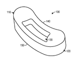
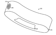
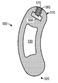
도 1a는 뼈 유합을 용이하게 하기 위하여 중앙 절결부(cutout)를 포함하는 예시적인 체간 스페이서의 사시도.
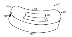
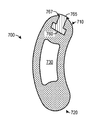
도 1b는 삽입 도구의 수나사형 팁을 수용하도록 구성된 암나사형 삽입체를 포함하는 체간 스페이서의 사시도.
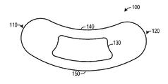
도 1c는 체간 스페이서의 측면도.
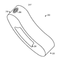
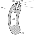
도 2a는 삽입 도구의 수나사형 팁을 수용하도록 구성된 둥근 암나사형 삽입체를 포함하는 예시적인 체간 스페이서의 사시도.
도 2b는 삽입 도구의 수나사형 팁을 수용하도록 구성된 8각형 암나사형 삽입체를 포함하는 체간 스페이서의 사시도.
도 3a는 나사형성 불가능한 재료를 사용하여 제조된 예시적인 체간 스페이서의 단면도.
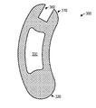
도 3b는 근위 단부에 공동이 형성된 나사형성 불가능한 체간 스페이서의 단면도.
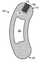
도 3c는 나사형성 가능한 재료가 공동 내로 삽입된 나사형성 불가능한 체간 스페이서의 단면도.
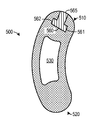
도 3d는 공동 내에 삽입된 나사형성 가능한 재료에 나삿니가 형성된 나사형성 불가능한 체간 스페이서의 단면도.
도 4a는 예시적인 나사형성 불가능한 체간 스페이서의 단면도로서, 체간 스페이서의 근위 단부에서의 테이퍼형 공동 내에 나사형성 가능한 재료가 삽입된 상태를 도시하는 단면도.
도 4b는 테이퍼형 공동 내에 삽입된 나사형성 가능한 재료에 나삿니가 형성된 나사형성 불가능한 체간 스페이서의 단면도.
도 5a는 예시적인 나사형성 불가능한 체간 스페이서의 단면도로서, 체간 스페이서의 근위 단부에서의 넓은 기부형 공동 내에 나사형성 가능한 재료가 삽입된 상태를 도시하는 단면도.
도 5b는 넓은 기부형 공동 내에 삽입된 나사형성 가능한 재료에 나삿니가 형성된 나사형성 불가능한 체간 스페이서의 단면도.
도 6a는 예시적인 나사형성 불가능한 체간 스페이서의 단면도로서, 체간 스페이서의 근위 단부에서의 공동 - 공동은 회전 방지 특징부를 포함함 - 내에 삽입된 나사형성 가능한 재료에 나삿니가 형성된 상태를 도시하는 단면도.
도 6b는 통기구를 포함하는 공동 내에 삽입된 나사형성 가능한 재료에 나삿니가 형성된 예시적인 나사형성 불가능한 체간 스페이서의 단면도.
도 6c는 수술용 임플란트의 근위 단부에서의 테이퍼형 공동 내에 삽입된 나사형성 가능한 재료의 사시도.
도 6d는 테이퍼형 공동 내에 삽입된 나사형성 가능한 재료를 포함하는, 수술용 임플란트의 근위 단부의 도면.
도 6e는 테이퍼형 공동 내에 삽입된 나사형성 가능한 재료에 나삿니가 형성된 수술용 임플란트의 국부 투시도(phantom view).
도 7a는 예시적인 나사형성 불가능한 체간 스페이서의 단면도로서, 체간 스페이서의 근위 단부에서의 넓은 기부형 공동 내에 나사형성 가능한 재료가 가압 끼워맞춤될 준비가 되어 있는 상태를 도시하는 단면도.
도 7b는 넓은 기부형 공동 내에 나사형성 가능한 재료가 가압 끼워맞춤되고 있는 나사형성 불가능한 체간 스페이서의 단면도.
도 7c는 넓은 기부형 공동 내에 나사형성 가능한 재료가 가압 끼워맞춤된 나사형성 불가능한 체간 스페이서의 단면도.
도 7d는 급확대(mushrooming)를 방지하도록 구성된 링을 사용하여 넓은 기부형 공동 내에 나사형성 가능한 재료가 가압 끼워맞춤되고 있는 나사형성 불가능한 체간 스페이서의 단면도.
도 7e는 나사형성 가능한 재료가 체간 스페이서의 공동 내에 가압 끼워맞춤됨에 따라 나사형성 가능한 재료의 급확대를 감소 또는 방지하도록 구성된 링의 사시도.
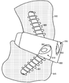
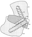
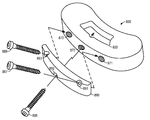
도 8a는 독립 실행형 전방 요추 체간 유합(STALIF) 임플란트에서의 사용을 위하여 뼈 나사를 각각 수용하도록 구성된 다수의 암나사형 삽입체들을 포함하는 나사형성 불가능한 체간 스페이서의 사시도.
도 8b는 STALIF 구성에서 뼈 나사를 수용하는 암나사형 삽입체를 포함하는 나사형성 불가능한 체간 스페이서의 절결도.
도 8c는 STALIF 구성에서의 사용을 위하여 뼈 나사를 수용하도록 구성된 다수의 암나사형 삽입체들을 포함하는, 뼈 나사 플레이트와 나사형성 불가능한 체간 스페이서의 사시도.
도 9a는 체간 스페이서 내에 형성된 암나사형 삽입체를 나사 결합식으로 고정하도록 구성된 수나사형 팁을 포함하는 예시적인 삽입 도구의 사시도.
도 9b는 예시적인 체간 스페이서 내에 형성된 암나사형 삽입체와 맞물리는 삽입 도구의 수나사형 팁의 확대 사시도.
도 10은 척추 영역 내의 제 위치에 있는 추간 스페이서와 맞물리는 삽입 도구의 사시도.
도 11은 체간 스페이서의 근위 단부 내에 암나사형 삽입체를 형성하는 하나의 방법의 플로우차트.Non-limiting and non-exhaustive embodiments of the present invention, including various embodiments of the present invention, are described with reference to the drawings.
BRIEF DESCRIPTION OF THE DRAWINGS Figure 1 a is a perspective view of an exemplary trunk spacer including a central cutout to facilitate bone union.
1B is a perspective view of a trunk spacer comprising a female inset configured to receive a male threaded tip of an insertion tool.
1C is a side view of a trunk spacer.
Figure 2a is a perspective view of an exemplary trunk spacer including a round female threaded insert configured to receive a male threaded tip of an insertion tool.
Figure 2b is a perspective view of a trunk spacer including an octagonal female inset configured to receive a male threaded tip of an insertion tool.
Figure 3a is a cross-sectional view of an exemplary trunk spacer fabricated using a non-threadable material.
Figure 3b is a cross-sectional view of a non-threadable bodily spacer having a cavity formed at its proximal end;
Figure 3c is a cross-sectional view of a non-threadable bodily spacer into which a threadable material is inserted into a cavity.
Figure 3d is a cross-sectional view of a non-threadable bodily spacer having threads threaded into a threadable material inserted in a cavity.
FIG. 4A is a cross-sectional view of an exemplary non-threadable bodily spacer, showing a state in which a threadable material is inserted within a tapered cavity at the proximal end of the bodily spacer. FIG.
4b is a cross-sectional view of a non-threadable bodily spacer having threads threaded into a threadable material inserted in a tapered cavity.
5A is a cross-sectional view of an exemplary non-threadable bodily spacer, with a threadable material inserted in a wider cavity at the proximal end of the bodily spacer.
5b is a cross-sectional view of a non-threadable bodily spacer having threads threaded into a threadable material inserted within a wider cavity.
FIG. 6A is a cross-sectional view of an exemplary non-threadable bodily spacer, wherein the cavity-cavity at the proximal end of the bodily spacer includes anti-rotation features;
6B is a cross-sectional view of an exemplary non-threadable bodily spacer having threads threaded into a threadable material inserted in a cavity containing a vent.
Figure 6c is a perspective view of a threadable material inserted within a tapered cavity at the proximal end of the surgical implant.
6D is a view of the proximal end of a surgical implant, including a threadable material inserted within a tapered cavity.
Figure 6e is a phantom view of a surgical implant having threads threaded into a tapered cavity.
7A is a cross-sectional view of an exemplary non-threadable bodily spacer, in cross-section illustrating a state in which a threadable material within a wider cavity at the proximal end of the bodily spacer is ready to press fit;
Figure 7b is a cross-sectional view of a non-threadable bodily spacer in which a threadable material is press-fit within a wider cavity.
7c is a cross-sectional view of a non-threadable bodily spacer with a press-fit material in a threadable material within a wider cavity.
Figure 7d is a cross-sectional view of a non-threadable bodily spacer in which a threadable material is press-fit within a wider hollow cavity using a ring configured to prevent mushrooming.
Figure 7e is a perspective view of a ring configured to reduce or prevent rapid enlargement of the threadable material as the threadable material is press fit within the bore space spacer.
8A is a perspective view of a non-threadable bodily spacer comprising a plurality of internally threaded inserts configured to respectively receive bone screws for use in a stand-alone anterior lumbar interbody fusion (STALIF) implant.
8B is a cutaway view of a non-threadable bodily spacer including a female threaded insert for receiving bone screws in a STALIF configuration.
Figure 8c is a perspective view of a bone screw plate and a non-threadable bodily spacer, including a plurality of female insets configured to receive a bone screw for use in a STALIF configuration.
9A is a perspective view of an exemplary insertion tool including a male threaded tip configured to threadably lock a female threaded insert formed within a trunk spacer.
Figure 9b is an enlarged perspective view of the male threaded tip of the insertion tool engaging the female type insert formed in the exemplary trunk spacer.
10 is a perspective view of an insertion tool engaged with an intervertebral spacer in position in the vertebral region;
11 is a flowchart of one method of forming a female inset in the proximal end of the interchain spacer.
하기의 설명에서, 본 명세서에 개시된 다양한 실시예들의 완전한 이해를 위하여 많은 특정 세부 사항들이 제공된다. 본 명세서에 개시된 시스템 및 방법은 특정 세부 사항들 중 하나 이상이 없이 실시될 수 있거나, 다른 방법, 구성요소, 재료 등에 의해 실시될 수 있다. 게다가, 일부 경우에, 본 발명의 태양들을 모호하게 하는 것을 피하기 위하여 잘 알려진 구조, 재료 또는 작동이 상세하게 도시 또는 설명되지 않을 수 있다. 또한, 하나 이상의 대안적인 실시예들에서 설명된 특징부들, 구조들 또는 특성들이 임의의 적합한 방식으로 조합될 수 있다.In the following description, numerous specific details are set forth in order to provide a thorough understanding of the various embodiments disclosed herein. The systems and methods disclosed herein may be practiced without one or more of the specific details, or may be practiced by other methods, components, materials, and so on. In addition, in some instances, well-known structures, materials, or operations may not be shown or described in detail to avoid obscuring aspects of the present invention. Also, the features, structures, or characteristics described in one or more of the alternative embodiments may be combined in any suitable manner.
본 발명은 삽입체와는 상이한 물리적 특성들을 갖는 하나 이상의 재료들로부터 형성된 임플란트의 공동 내에 삽입체를 형성하기 위한 장치, 시스템 및 방법을 설명한다. 예를 들어, 용이하게 나사형성 가능한 재료로부터 만들어진 삽입체는 대체로 나사형성 불가능한 재료로부터 형성된 임플란트 상에 또는 그 내부에 위치될 수 있다. 보다 일반적으로, 특정 연결 특징부를 형성하기에 바람직하거나 적합한 재료를 포함하는 삽입체가, 특정의 요구되는 연결 특징부를 형성하기에 대체로 적합하지 않은 재료로 만들어진 임플란트 상에 또는 그 내에 위치될 수 있다.The present invention describes an apparatus, system and method for forming an implant within a cavity of an implant formed from one or more materials having different physical properties than the implant. For example, an insert made from an easily threadable material can be placed on or within an implant formed from a generally non-threadable material. More generally, an implant comprising a material suitable or suitable for forming a particular connecting feature may be placed on or within an implant made of a material that is substantially unsuitable for forming a particular desired connecting feature.
다양한 실시예들에 따르면, 체간 스페이서는 근위 단부와 원위 단부(distal end)를 포함할 수 있다. 체간 스페이서는 질화규소 세라믹, 다른 세라믹 재료, 유리 재료 또는 고 다공성 재료와 같은 나사형성 불가능한 재료를 사용하여 제조될 수 있다. 공동이 예를 들어 근위 단부에서와 같이 체간 스페이서 내에 형성될 수 있다. 나사형성 가능한 재료가 공동 내에 삽입될 수 있다. 나사형성 불가능한 체간 스페이서 내에 암나사형 삽입체를 형성하기 위하여 나사형성 가능한 재료가 이어서 나사형성될 수 있다. 수나사형 팁을 갖고 구성된 삽입 도구가 이어서 사용되어 수술 동안 암나사형 삽입체를 통하여 체간 스페이서를 나사 결합식으로 고정할 수 있다. 다른 실시예들에서, 삽입체(들)는 예를 들어 독립형 전방 요추 체간 유합("STALIF") 임플란트에서와 같이 뼈 나사를 수용하도록 보다 큰 나삿니를 갖고 구성될 수 있다.According to various embodiments, trunk spacers may include a proximal end and a distal end. The trunk spacers can be made using materials that are not threadable, such as silicon nitride ceramics, other ceramic materials, glass materials, or high porosity materials. The cavity may be formed in the trunk spacer, for example at the proximal end. A threadable material can be inserted into the cavity. A threadable material may then be threaded to form a female threaded insert in the non-threadable bodily spacer. An insertion tool constructed with a male threaded tip can then be used to secure the trunk spacer through the female threaded insert during surgery. In other embodiments, the insert (s) can be configured with larger threads to accommodate the bone screws, such as in a stand-alone anterior lumbar interbody fusion ("STALIF ") implant.
질화규소 세라믹을 포함하는 스페이서의 일부 실시예에서, 질화규소 세라믹은 도핑된 질화규소 세라믹을 포함할 수 있다. 적합한 질화규소 재료의 예가, 예를 들어 본 명세서에 참고로 포함된, 발명의 명칭이 "금속-세라믹 복합물 관절(Metal-Ceramic Composite Articulation)"인 미국 특허 제6,881,229호에 개시되어 있다. 일부 실시예에서, 알루미나(Al2O3), 이트리아(Y2O3), 산화마그네슘 및/또는 산화스트론튬과 같은 도펀트가 처리되어 질화규소의 도핑된 조성물을 형성할 수 있다. 도핑된 질화규소 또는 다른 유사한 세라믹 재료를 포함하는 실시예에서, 최고 밀도, 기계적 특성 및/또는 항균 특성을 달성하도록 도펀트 양이 최적화될 수 있다. 추가의 실시예에서, 생체적합성 세라믹은 약 90 Mpa 초과의 휨 강도( flexural strength) 및 약 9 MPa.m1/2 초과의 인성(toughness)을 가질 수 있다. 휨 강도는 미국 재료 시험 협회(American Society for Testing of Metals, ASTM) 프로토콜 방법 C-1161에 따라 표준 3점 굽힘 시편들 상에서 측정될 수 있으며, 파괴 인성은 ASTM 프로토콜 방법 E399에 따라 단일 에지 노치 형성된 빔 시편을 사용하여 측정될 수 있다. 일부 실시예에서, 세라믹 임플란트를 형성하기 위하여 질화규소의 분말이 단독으로 또는 위에서 언급된 도펀들 중 하나 이상과 조합하여 사용될 수 있다.In some embodiments of spacers comprising silicon nitride ceramics, the silicon nitride ceramics may comprise doped silicon nitride ceramics. An example of a suitable silicon nitride material is disclosed, for example, in U.S. Patent No. 6,881,229, entitled " Metal-Ceramic Composite Articulation ", the disclosure of which is incorporated herein by reference. In some embodiments, the alumina (Al 2 O 3), yttria (Y 2 O 3), the dopant is processed, such as magnesium oxide and / or strontium oxide to form a dope composition of the silicon nitride. In embodiments that include doped silicon nitride or other similar ceramic materials, the amount of dopant may be optimized to achieve the highest density, mechanical and / or antimicrobial properties. In a further embodiment, the biocompatible ceramic may have a flexural strength of greater than about 90 Mpa and a toughness of greater than about 9 MPa.m < 1/2 >. The flexural strength can be measured on standard three-point bend specimens according to the American Society for Testing of Metals (ASTM) protocol method C-1161, and the fracture toughness can be measured in accordance with ASTM protocol method E399 using a single edge notched beam Can be measured using a specimen. In some embodiments, a powder of silicon nitride may be used alone or in combination with one or more of the above-mentioned dopants to form a ceramic implant.
적합한 질화규소 재료의 다른 예가, 본 명세서에 참고로 또한 포함된, 발명의 명칭이 "세라믹-세라믹 관절 표면 임플란트(Ceramic-Ceramic Articulation Surface Implants)"인 미국 특허 제7,666,229호에 개시되어 있다. 적합한 질화규소 재료의 또 다른 예가, 본 명세서에 참고로 또한 포함된, 발명의 명칭이 "모노블록 세라믹 절구 컵을 갖는 고관절 보철물(Hip Prosthesis with Monoblock Ceramic Acetabular Cup)"인 미국 특허 제7,695,521호에 개시되어 있다.Another example of a suitable silicon nitride material is disclosed in U.S. Patent No. 7,666,229, entitled " Ceramic-Ceramic Articulation Surface Implants ", which is also incorporated herein by reference. Another example of a suitable silicon nitride material is disclosed in U.S. Patent No. 7,695,521, entitled " Hip Prosthesis with Monoblock Ceramic Acetabular Cup ", the title of which is also incorporated herein by reference. have.
다양한 실시예들에 따르면, 나사형성 불가능한 체간 스페이서로부터 나사형성 가능한 재료가 회전 또는 분리되는 것을 감소 또는 방지하도록 공동이 형상화될 수 있다. 예를 들어, 공동은 사각형, 타원형, 육각형, 팔각형, 다각형 및/또는 다른 비원형 형상일 수 있다. 부가적으로, 공동은 테이퍼 형성될 수 있으며, 회전 방지 형성 특징부를 포함할 수 있고/있거나 통기구를 포함할 수 있다. 공동은 초기 제조 공정 동안에 형성될 수 있거나, 후처리 단계에서 예를 들어 기계적인 드릴링, 화학적 에칭, 레이저 에칭, 입자 블라스팅 및/또는 다른 공동 형성 공정의 사용을 통하여 나중에 형성될 수 있다.According to various embodiments, the cavity may be shaped to reduce or prevent the threadable material from rotating or separating from the non-threadable bodily spacers. For example, the cavity may be rectangular, oval, hexagonal, octagonal, polygonal and / or other non-circular shapes. Additionally, the cavity may be tapered, may include anti-rotation features and / or may include a vent. The cavities may be formed during the initial fabrication process or may be formed later in the post-process step, for example, through the use of mechanical drilling, chemical etching, laser etching, particle blasting and / or other cavitation processes.
공동 내로 삽입되는 재료는 PEEK(폴리에테르에테르케톤), 폴리프로필렌, 티타늄, 금속, 합금, 및/또는 상기 재료가 내부에 배치되는 재료에는 존재하지 않는 원하는 특성을 갖는 다른 재료를 포함할 수 있다. 예를 들어, 재료는 나사형성될 수 있거나, 스페이서의 주 재료 또는 재료들보다 더 강성이거나 달리 더 바람직한 나삿니를 형성할 수 있다. 가압 끼워맞춤, 사출 성형, 압출, 접착 또는 용융을 포함하지만 이로 한정되지 않는 매우 다양한 삽입 공정들 중 임의의 공정을 사용하여, 나사형성 가능한 재료가 공동 내에 삽입될 수 있다. 일부 실시예에 따르면, 삽입 공정들의 조합이 이용될 수 있다. 예를 들어, PEEK 재료가 공동 내로 사출되고 나서 더 가압되어 삽입을 완결시킬 수 있다.The material inserted into the cavity may comprise PEEK (polyetheretherketone), polypropylene, titanium, a metal, an alloy, and / or other materials having desired properties that are not present in the material in which the material is disposed. For example, the material may be threaded or may form a thread that is stiffer or otherwise more preferred than the main material or materials of the spacer. Using any of a wide variety of inserting processes including, but not limited to, press fit, injection molding, extrusion, bonding or melting, the threadable material can be inserted into the cavity. According to some embodiments, a combination of insertion processes may be used. For example, the PEEK material may be injected into the cavity and then further pressurized to complete the insertion.
나사형성 가능한 재료는 이어서 나사형성됨으로써, 공동 내에 암나사형 삽입체를 형성할 수 있다. 대안적으로, 일부 다른 유형의 지지부를 제공하도록 구성된 공동 내로 재료가 삽입될 수 있다. 예를 들어, STALIF 임플란트에서 예를 들어 뼈 나사를 지지하기 위한 구조적 지지부를 제공하기 위하여, 다양한 의학적 지지 및 조작 장치와 상호작용하기 위하여, 삽입 도구와 상호 작용하기 위하여 그리고/또는 접촉 지점을 제공하기 위하여, 체간 스페이서 내에 형성된 하나 이상의 공동들 내에 재료가 삽입될 수 있다. 예를 들어, 어떤 세라믹 체간 스페이서는 점 하중 하에서 파괴되기 쉬울 수 있다. 따라서, 점 하중의 예상된 위치에 공동이 형성될 수 있으며, 공동은 점 하중을 지지할 수 있는 제2 재료로 충전될 수 있다. 제2 재료가 반드시 나사형성 가능할 필요는 없다.The threadable material is then threaded to form a female insert in the cavity. Alternatively, the material may be inserted into a cavity configured to provide some other type of support. For example, in order to provide structural support for supporting bone screws, for example, in STALIF implants, it may be desirable to interact with a variety of medical support and manipulation devices, to interact with the insertion tool and / The material may be inserted into one or more cavities formed in the intergrowth spacer. For example, some ceramic trunk spacers may be susceptible to fracture under point loads. Thus, a cavity may be formed at the expected location of the point load, and the cavity may be filled with a second material capable of supporting the point load. The second material need not necessarily be threadable.
본 명세서 전체에서 "일 실시예" 또는 "실시예"에 대한 언급은 실시예와 관련하여 설명된 특정 특징부, 구조 또는 특성이 적어도 하나의 실시예에 포함됨을 의미한다. 따라서, 본 명세서 전체의 많은 곳에 있는 구문 "일 실시예에서" 또는 "실시예에서"의 출현은 모두가 반드시 동일한 실시예를 언급하는 것은 아니다. 특히, "실시예"는 시스템, 제조 물품, 방법 또는 공정의 생산물일 수 있다.Reference throughout this specification to "one embodiment" or "an embodiment " means that a particular feature, structure, or characteristic described in connection with the embodiment is included in at least one embodiment. Thus, the appearances of the phrase "in one embodiment" or "in an embodiment" in many places throughout this specification are not necessarily all referring to the same embodiment. In particular, "an embodiment" may be a product of a system, article of manufacture, method or process.
본 명세서 내에서 사용된 구문 "나사형성 불가능한" 및 유사한 용어들은 오직 나사형성이 불가능하거나 비실용적인 재료만을 포함할 필요는 없다. 오히려, "나사형성 불가능한"은 손쉽게 나사형성 가능하지 않은, 즉 용이하게 나사형성 가능하지 않은 재료, 및/또는 나사형성될 때 약하거나 달리 적합하지 않은 나삿니를 생성하는 재료를 포함하는 것으로 의도된다. 따라서, 본 명세서에 사용되는 바와 같은 "나사형성 불가능한 재료"는 실제로 어렵거나 고가이거나 성가신 공정들을 통하여 나사형성 가능한 것일 수 있다. 더욱이, 본 명세서에 사용되는 바와 같은 "나사형성 불가능한 재료"는 실제로 나사형성 가능할 수 있지만, 나삿니가 특정 목적에 적합하지 않을 수 있다(예를 들어, 나삿니가 용이하게 벗겨지고 파손되고 굽혀지고 그리고/또는 그렇지 않으면 적당한 하중을 지지할 수 없다). "나사형성 불가능한" 재료의 예는 질화규소 세라믹과 같은 세라믹 그리고 유리 재료를 포함하지만 이로 한정되지 않는다.The phrases "non-threadable" and similar terms used herein need not include only materials that are not threadable or impractical. Rather, "non-threadable" is intended to include materials that are not readily threadable, i.e., not easily threadable, and / or produce threads that are weak or otherwise unfavorable when threaded. Thus, "non-threadable material" as used herein may be one that is actually difficult, expensive, or threadable through cumbersome processes. Moreover, the "non-threadable material" as used herein may actually be threadable, but threads may not be suitable for a particular purpose (eg, threads are easily peeled, broken, bent and / Or otherwise not support the proper load). Examples of "non-threadable" materials include, but are not limited to, ceramics such as silicon nitride ceramics and glass materials.
본 명세서에 개시된 실시예와 함께 사용될 수 있는 기반시설 및 제조 도구 및/또는 기계, 예를 들어 압출기, 프레스, 사출기, 체간 스페이서, 나사형성 도구 및 나사형성 기계 중 일부는 이미 입수 가능하다. 일부 실시예들의 체간 스페이서는 추간 스페이서 또는 극돌기간(interspinous) 스페이서로서 사용될 수 있으며, 또한 후방 안정화 시스템 및 동적 로드 안정화(dynamic rod stabilization) 시스템과 함께 사용될 수 있다. STALIF, PLIF 및 TLIP 접근법을 포함하지만 이로 한정되지 않는 임의의 다양한 삽입 도구들 및 삽입 기술들이 다양한 실시예들과 관련하여 이용될 수 있다.Some of the infrastructure and manufacturing tools and / or machines that can be used with the embodiments disclosed herein, such as extruders, presses, injectors, baffle spacers, threading tools and thread forming machines, are already available. The trunk spacers of some embodiments may be used as intervertebral spacers or interspinous spacers and may also be used with a posterior stabilization system and a dynamic rod stabilization system. Any of a variety of insertion tools and insertion techniques, including but not limited to STALIF, PLIF and TLIP approaches, may be used in connection with various embodiments.
본 명세서 내의 도면에서 일반적으로 설명되고 도시된 바와 같은 실시예들의 구성 요소들은 매우 다양한 다른 구성들로 배열 및 설계될 수 있다. 다른 예에서, 본 예시적인 실시예들의 설명을 불필요하게 모호하게 하는 것을 피하기 위하여 체간 유합과 연관된 공지의 구조는 상세하게 도시되거나 설명되지 않는다. 게다가, 설명된 방법의 단계는 반드시 임의의 특정 순서로 또는 심지어 순차적으로 실행될 필요는 없으며, 또한 달리 특정되지 않는다면 단계들이 단지 한 번만 실행될 필요도 없다. 예를 들어, 본 명세서 내에 설명된 예시적인 방법에서의 단계들 중 일부 단계들은, 일부 구현예에서, 동시에 수행될 수 있다.The components of the embodiments as generally described and illustrated in the figures herein may be arranged and designed in a wide variety of different configurations. In other instances, well-known structures associated with trunk joints are not shown or described in detail in order to avoid unnecessarily obscuring the description of the present exemplary embodiments. In addition, the steps of the described method do not necessarily need to be performed in any particular order or even sequentially, and steps need not be performed only once unless otherwise specified. For example, some of the steps in the exemplary method described herein may, in some implementations, be performed concurrently.
본 발명의 실시예는, 전체에 걸쳐 유사한 부분들이 유사한 도면 부호들로 지시된 도면을 참고하여 가장 잘 이해된다. 하기의 설명에서, 다양한 실시예들의 완전한 이해를 부여하기 위하여 많은 세부 사항들이 제공된다. 그러나, 본 명세서 내에 개시된 실시예들은 특정 세부 사항들 중 하나 이상 없이 실시될 수 있거나, 다른 방법, 구성요소, 재료 등에 의해 실시될 수 있다. 다른 예에서, 본 발명의 태양들을 모호하게 하는 것을 피하기 위하여 잘 알려진 구조, 재료 또는 작동이 상세하게 도시 또는 설명되지 않는다.BRIEF DESCRIPTION OF THE DRAWINGS Embodiments of the present invention are best understood by reference to the drawings, wherein like parts are designated by like reference numerals throughout. In the following description, numerous specific details are set forth in order to provide a thorough understanding of various embodiments. However, the embodiments disclosed herein may be practiced without one or more of the specific details, or may be embodied by other methods, components, materials, and so on. In other instances, well-known structures, materials, or operations are not shown or described in detail to avoid obscuring aspects of the present invention.
도 1a는 체간 스페이서(100)의 사시도이다. 체간 스페이서(100)는 질화규소 세라믹 또는 다른 세라믹과 같은 나사형성 불가능한 재료를 사용하여 제조될 수 있으며, 오목한 전방면(140)과 볼록한 후방면(150)을 갖는 아치형 록커-유사(rocker-like) 형상을 가질 수 있다. 체간 스페이서(100)는 개구(130)와 같은 하나 이상의 구멍, 관통 보어, 개구, 또는 중공부를 포함할 수 있다. 다양한 실시예들에 따르면, 체간 스페이서(100)는 근위 단부(110)와 원위 단부(120)를 가질 수 있다. 원위 단부(120)는 삽입 동안에 선단 에지(leading edge)일 수 있으며, 이때 근위 단부(110)는 외과 의사에 가장 근접한다. 대안적으로, 체간 스페이서(100)는 임의의 대안적인 배향으로 수술적으로 삽입될 수 있다.1A is a perspective view of a
도 1b는 삽입 도구의 수나사형 팁을 수용하도록 구성된 암나사형 삽입체(160)를 포함하는 체간 스페이서(100)의 다른 사시도이다. 도시된 바와 같이, 암나사형 삽입체(160)는 체간 스페이서(100)의 근위 단부(110)에 위치될 수 있다. 대안적으로, 다수의 암나사형 삽입체(160)들 또는 다른 삽입체들이 체간 스페이서(100) 상의 다양한 위치들에 위치될 수 있다. 예를 들어, 하나 이상의 암나사형 삽입체들(또는 다른 삽입체들)이 원위 단부(120), 전방면(140), 후방면(150), 상부 표면 및/또는 바닥 표면 상에 위치될 수 있다. 도 1c는 근위 단부(110), 원위 단부(120), 전방면(140) 및 후방면(150)을 포함하는 체간 스페이서(100)의 측면도를 제공한다.1B is another perspective view of
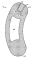
도 2a는 체간 스페이서(200)의 대안적인 실시예의 사시도이다. 체간 스페이서(200)는 체간 스페이서(200)의 근위 단부(210)에 위치된 둥근 암나사형 삽입체(260)를 포함한다. 체간 스페이서(200)의 수술적인 삽입 동안에 삽입 도구의 수나사형 팁은 암나사형 삽입체(260)를 나사 결합식으로 고정할 수 있다. 삽입 도구는 이어서 수술적 삽입 동안에 선단 에지로서 체간 스페이서(200)의 원위 단부(220)를 안내할 수 있다. 개구(230)는 뼈 형태 형성 단백질(bone morphogenic protein, BMP)을 위한 장소로서 역할할 수 있다.Figure 2a is a perspective view of an alternate embodiment of trunk spacer (200). The
도 2b는 삽입 도구의 수나사형 팁을 수용하도록 구성된 8각형 암나사형 삽입체(265)를 포함하는 체간 스페이서(200)의 다른 사시도이다. 다양한 실시예들에 따르면, 나사형성 불가능한 체간 스페이서(200)의 근위 단부(210)에 8각형 공동이 형성될 수 있다. 나사형성 가능한 재료가 이어서 8각형 공동 내에 삽입될 수 있다. 나사형성 가능한 재료는 이어서 암나사형 삽입체(265)를 형성하기 위하여 나사형성될 수 있다. 암나사형 삽입체(265)의 8각형 형상은 암나사형 삽입체(265)가 공동 내에서 회전할 가능성을 줄일 수 있다. 즉, 원형 이외의 형상을 갖는 공동 내에 나사형성 가능한 재료를 삽입함으로써, 나사형성 가능한 재료가 공동 내에서 분리 및 회전할 가능성은 감소된다.Figure 2B is another perspective view of
따라서, 삽입체(265)는 삽입체(265)의 형상이 삽입체가 그의 대응하는 공동 내에서 회전되는 것을 방지한다는 점에서 회전 방지 특징부를 포함한다. 그러나, 8각형 형상 자체는 삽입체(265)가 그의 공동으로부터 제거되는 것을 반드시 방지할 필요는 없기 때문에, 삽입체(265)가 또한 보유 특징부를 반드시 포함하는 것은 아니다(그러나, 원한다면 별도의 보유 특징부가 제공될 수 있다). 그러나, 전체로서 본 명세서를 검토한 이후에 명백해지는 바와 같이, 그러한 특징부들이 회전을 억제하고 삽입체가 공동으로부터 제거되는 것을 방지하는 데 도움을 준다면, 일부 회전 방지 특징부들은 또한 보유 특징부를 포함할 수 있다.Thus, the
도 3a는 나사형성 불가능한 재료를 사용하여 제조된 체간 스페이서(300)의 단면도이다. 예를 들어, 체간 스페이서(300)는 질화규소 세라믹, 다른 세라믹 또는 관련된 복합 재료를 사용하여 제조될 수 있다. 체간 스페이서(300)는 원위 단부(320), 근위 단부(310) 및 개구(330)를 포함할 수 있다. 도 3b에 도시된 바와 같이, 공동(360)은 체간 스페이서(300)의 근위 단부(310)에 형성될 수 있다.3A is a cross-sectional view of a
공동(360)은 임의의 형상, 폭, 길이, 깊이 및/또는 테이퍼형 구성을 갖도록 형성될 수 있다. 더욱이, 매우 다양한 보유 특징부들 및/또는 회전 방지 특징부들 중 임의의 것이 공동(360)의 연장 부분들에 의해 형성될 수 있다. 부가적으로, 다수의 공동들이 체간 스페이서(300)에 형성될 수 있으며, 근위 단부(310)에 더하여 또는 그의 대안으로서, 다양한 위치들에 위치될 수 있다. 공동(360)은 드릴링, 화학적 에칭, 레이저 에칭, 입자 블라스팅에 의하여 그리고/또는 다른 재료 제거 공정들을 통하여 형성될 수 있다.The
대안적으로, 공동은 제조 단계 동안에, 예를 들어 공동을 제공하도록 구성된 금형들의 사용을 통하여 체간 스페이서(300)에 형성될 수 있다. 다시 말하면, 공동은 소성(firing) 후에 공동을 기계가공하는 대신에, 미가공 상태(green state) 동안에 질화규소 세라믹에 또는 다른 소결용 재료에 형성될 수 있다. 그러한 실시예는 재료를 제거할 필요성을 없앨 수 있고/있거나 충분한 공동을 형성하기 위하여 제거될 필요가 있는 재료의 양을 줄일 수 있다.Alternatively, the cavity may be formed in the
도 3c에 도시된 바와 같이, 나사형성 가능한 재료(365)가 공동(360) 내로 삽입될 수 있다. 나사형성 가능한 재료(365)는 실질적으로 공동(360)을 충전하도록 구성될 수 있다. 나사형성 가능한 재료(365)는 PEEK, 폴리프로필렌, 티타늄, 알루미늄, 다른 금속, 합금, 에폭시 및/또는 나사형성될 수 있는 임의의 다른 재료를 포함할 수 있다. 가압 끼워맞춤, 사출 성형, 압출, 접착 또는 용융을 포함하지만 이로 한정되지 않는 매우 다양한 삽입 공정들 중 임의의 공정을 사용하여, 나사형성 가능한 재료(365)가 공동(360) 내로 삽입될 수 있다. 공동(360)을 넘쳐 흐를 수 있는 과잉 재료(365)는 매끄럽게 사포질(sanding)되거나 달리 제거되어, 도 3c에 도시된 바와 같이 나사형성 가능한 재료(365)의 표면이 체간 스페이서(300)의 표면과 같은 높이가 되게 한다.3C, a
도 3d는 나사형성 가능한 재료(365)가 나사형성되어 암나사형 삽입체(370)를 형성한 후의 체간 스페이서(300)의 단면도를 도시한다. 암나사형 삽입체(370)는 수나사형 삽입 도구와, 또는 나사, 볼트, 로드(rod) 등과 같은 고정 부재와 정합하도록 구성될 수 있다. 따라서, 나사형성 불가능한 체간 스페이서(300)는 암나사형 삽입체(370)를 갖도록 구성될 수 있어, 나사형성 불가능한 체간 스페이서가 삽입 도구에 의하여 나사 결합식으로 고정될 수 있게 한다.FIG. 3D shows a cross-sectional view of
도 4a는 나사형성 불가능한 체간 스페이서(400)의 다른 실시예를 도시하는 도면으로서, 체간 스페이서(400)의 근위 단부(410)에 형성된 테이퍼형 공동(460) 내에 나사형성 가능한 재료(465)가 삽입된 상태를 도시한다. 체간 스페이서(400)는 근위 단부(410), 원위 단부(420) 및 개구(430)가 있는 아치 형상을 갖는 것으로서 도시되어 있다. 그러나, 체간 스페이서(400)의 형상, 규격 및 치수는 특정 응용을 위하여 조정되거나 수정될 수 있다.4A illustrates another embodiment of a non-threadable
도시된 실시예에서, 테이퍼형 공동(460)은 체간 스페이서(400)의 근위 단부(410) 부근에서 더 넓고, 체간 스페이서(400)의 원위 단부(420)를 향하여 더 좁다. 대안적인 실시예에서, 테이퍼형 공동(460)은 체간 스페이서(400)의 원위 단부(420) 부근에서 더 넓을 수 있고 체간 스페이서(400)의 근위 단부(410) 부근에서 더 좁을 수 있다.In the illustrated embodiment, the
도 4b에 도시된 바와 같이, 공동(460) 내에 암나사형 삽입체(470)를 형성하기 위하여 나사형성 가능한 재료(465)가 나사형성될 수 있다.As shown in FIG. 4B, a
나삿니의 크기 및 형상은 다양한 삽입 도구들 및/또는 체결구들과의 호환성을 위하여 조정될 수 있다.The size and shape of the threads can be adjusted for compatibility with various insertion tools and / or fasteners.
도 5a는 나사형성 불가능한 체간 스페이서(500)의 다른 실시예를 도시하는 도면으로서, 체간 스페이서(500)의 근위 단부(510)에서의 넓은 기부형 공동(560) 내에 나사형성 가능한 재료(565)가 삽입된 상태를 도시한다. 넓은 기부형 공동(560)은 공동에 의하여 형성되는 삽입체의 대향 단부들에서 보유 특징부를 형성하는 데 사용될 수 있으며, 보유 특징부는 이하에서 보다 상세하게 설명되는 바와 같이 안정성을 제공할 수 있고 스페이서로부터 임플란트의 제거 및/또는 스페이서 내에서 임플란트의 회전을 방지하는 것을 도울 수 있다.5A illustrates another embodiment of a non-threadable
도면에 도시된 바와 같이, 넓은 기부형 공동(560)은 체간 스페이서(500)의 원위 단부(520)를 향하는 연장된 공동 영역(561, 562)들을 포함할 수 있다. 따라서, 체간 스페이서(500)의 근위 단부(510) 부근의 넓은 기부형 공동(560)의 개구는 넓은 기부형 공동(560)의 기부보다 실질적으로 더 좁을 수 있다. 일단 나사형성 가능한 재료(565)가 넓은 기부형 공동(560) 내에서 고화되거나 달리 고정되면, 나사형성 가능한 재료(565)가 공동(560)으로부터 쉽게 제거될 수 없다는 점에서, 넓은 기부형 공동(560)은 이점을 제공할 수 있다.As shown in the figure, the
나사형성 가능한 재료(565)는 넓은 기부형 공동(560) 내에서 용융, 가압 끼워맞춤 또는 사출될 수 있다. 일단 넓은 기부형 공동(560) 내에서 완전히 경화, 고화 및/또는 달리 고정되면, 연장된 공동(561, 562)들은 나사형성 가능한 재료(565)의 제거를 방지할 수 있다. 더욱이, 연장된 공동 영역(561, 562)들의 형상에 따라, 이들은 부가적으로 나사형성 가능한 재료(565)가 넓은 기부형 공동(560) 내에서 회전할 가능성을 방지하거나 줄이는 회전 방지 특징부로서 역할할 수 있다.The
도 5b에 도시된 바와 같이, 넓은 기부형 공동(560) 내에 암나사형 삽입체(570)를 형성하기 위하여, 나사형성 가능한 재료(565)는 나사형성될 수 있다. 이어서, 매우 다양한 삽입 도구들 및/또는 체결구들 중 임의의 것이 암나사형 삽입체(570)에 나사 결합식으로 고정될 수 있다. 암나사형 삽입체(570)를 통한 수술적 삽입 동안에, 삽입 도구가 체간 스페이서(500)를 나사 결합식으로 고정할 수 있다.5b, the
전술한 바와 같이, 개구(530)는 BMP를 위한 전달 기구로서 역할을 할 수 있고/있거나 부가적인 뼈 성장을 위한 위치를 제공할 수 있다. 체간 스페이서(500)는, 예를 들어 나사형성 불가능한 질화규소 또는 다른 세라믹, 유리 및/또는 다른 나사형성 불가능한 재료를 포함할 수 있다. 나사형성 가능한 재료(565)는, 예를 들어 PEEK, 폴리프로필렌, 티타늄, 알루미늄, 다른 금속, 합금, 에폭시, 및/또는 나사형성될 수 있거나 스페이서(500)를 구성하는 재료(들)보다 나삿니 형성에 적어도 더 적합한 다른 재료를 포함하는 것이 바람직하다.As described above, the
도 6a는 나사형성 불가능한 체간 스페이서(600)의 다른 실시예의 단면도로서, 체간 스페이서(600)의 근위 단부(610)에서의 공동(660) 내에 삽입된 나사형성 가능한 재료(665)의 삽입체에 나삿니(670)가 형성된 상태를 도시하는 단면도이다. 도시된 바와 같이, 공동(660)은 회전 방지 및/또는 보유부 형성 공동을 포함함으로써 회전 방지 부재 및/또는 보유 부재(661)를 형성할 수 있다. 나사형성 가능한 재료(665)는 회전 방지 및/또는 보유부 형성 공동 내에 삽입될 수 있다. 따라서, 나사형성 가능한 재료(665)에 형성된 나삿니(670)에 회전력이 가해짐에 따라, 회전 방지 부재(661)는 나사형성 가능한 재료(665)가 공동(660) 내에서 회전할 가능성을 방지하거나 줄일 수 있고, 게다가 또는 대안적으로 삽입체가 임플란트로부터 제거될 수 있는 가능성을 방지하거나 줄일 수 있다.6A is a cross-sectional view of another embodiment of a non-threadable
도 6b는 공동(660) 내에 삽입된 나사형성 가능한 재료(665)에 나삿니(670)가 형성된 체간 스페이서(600)의 단면도이다. 도시된 실시예에서, 공동(660)은 공동(660)으로부터 원위 단부(620)에 더 가까운 측부 개구로 연장되는 통기구(661)를 포함한다. 통기구(661)는 임의의 형상, 직경 또는 길이일 수 있다. 나사형성 가능한 재료(665)가 삽입됨에 따라 통기구(661)는 공동(660) 내의 공기가 빠져 나가게 함으로써, 공동(660) 내에 갇힐 수 있는 가스의 가능성 및/또는 양을 줄일 수 있다. 부가적으로, 통기구(661)는 나사형성 가능한 재료(665)가 공동(660) 내에서 회전하는 것을 방지하기 위한 회전 방지 부재를 형성하는 데 사용될 수 있다.6B is a cross-sectional view of
다시 한번, 개구(630)는 BMP를 위한 전달 기구로서 역할을 할 수 있고/있거나 부가적인 뼈 성장을 위한 위치를 제공할 수 있다. 체간 스페이서(600)는 나사형성 불가능한 질화규소 또는 다른 세라믹, 유리 및/또는 다른 재료를 포함할 수 있다. 나사형성 가능한 재료(665)는 PEEK, 폴리프로필렌, 티타늄, 알루미늄, 다른 금속, 합금, 에폭시 및/또는 나사형성될 수 있는 다른 재료를 포함할 수 있다.Once again, the
도 6c는 수술 임플란트(680)의 근위 단부(681)에서의 테이퍼형 공동(687) 내에 위치된 삽입체(685)의 사시도이다. 삽입체(685)는 나사형성 가능한 재료로 구성될 수 있다. 다양한 실시예들에 따르면, 수술용 임플란트(680)는 테이퍼형 원위 단부(682) 및 하나 이상의 맞물림 특징부(683, 684)들을 포함할 수 있다. 테이퍼형 공동(687)의 개구는 수술용 임플란트(680)의 근위 단부(681)에 위치될 수 있다. 도시된 바와 같이, 테이퍼형 공동(687)의 기부는 테이퍼형 공동(687)의 개구보다 더 넓을 수 있다. 일단 나사형성 가능한 재료(685)가 테이퍼형 공동(687) 내에서 고화되거나 달리 고정되면, 나사형성 가능한 재료(685)가 테이퍼형 공동(687)으로부터 쉽게 제거될 수 없다는 점에서 테이퍼형 공동(687)은 이점을 제공할 수 있다.6C is a perspective view of an
다양한 실시예들에 따르면, 나사형성 가능한 재료(685)는 테이퍼형 공동(687) 내에서 용융, 가압 끼워맞춤 또는 사출될 수 있다. 나사형성 가능한 재료(685)는 PEEK, 폴리프로필렌, 티타늄, 알루미늄, 다른 금속, 합금, 에폭시 및/또는 나사형성될 수 있는 다른 재료를 포함할 수 있다. 테이퍼형 공동(687)의 더 넓은 원위 단부는 나사형성 가능한 재료(685)의 제거를 방지할 수 있다. 일부 실시예에서, 삽입체(685)가 테이퍼형 공동(687) 내에서 회전할 가능성을 방지하거나 적어도 줄이기 위하여, 하나 이상의 회전 방지 특징부들이 또한 제공될 수 있다.According to various embodiments, the
도 6d는 테이퍼형 공동(687) 내에 위치된 삽입체(685)를 포함한, 수술용 임플란트(680)의 근위 단부(681)의 도면이다. 테이퍼형 공동(687)의 원위 단부에서의 나사형성 가능한 재료(685)는 테이퍼형 공동(687)의 근위 개구보다 더 크다. 따라서, 일단 나사형성 가능한 재료가 테이퍼형 공동(687) 내에서 완전히 고정되면, 나사형성 가능한 재료(685)는 테이퍼형 공동(687)으로부터 당겨질 수 없다.6D is a view of the
도 6e는 수술용 임플란트(680)의 사시적인 국부 투시도이다. 이 도면에 도시된 바와 같이, 삽입체(685)는 테이퍼형 공동(687) 내에 위치되며, 테이퍼형 공동(687) 내에 암나사형 삽입체를 형성하기 위하여 나삿니(690)를 포함할 수 있다. 이어서, 매우 다양한 삽입 도구들 및/또는 체결구들 중 임의의 것이 암나사형 삽입체(685)에 나사 결합식으로 고정될 수 있다. 예를 들어, 암나사형 삽입체(685)를 통한 삽입, 제거 또는 조작 동안에, 삽입 도구는 수술용 임플란트(680)를 나사 결합식으로 고정시킬 수 있다.6E is a perspective local perspective view of the
도 7a는 근위 단부(710), 원위 단부(720) 및 개구(730)를 포함하는 나사형성 불가능한 체간 스페이서(700)의 단면도이다. 체간 스페이서(700)는 개구보다 더 넓은 기부를 갖고 구성된 넓은 기부형 공동(760)을 포함할 수 있다. 일 실시예에 따르면, 나사형성 가능한 재료(765)는 체간 스페이서(700)의 근위 단부(710)에서의 넓은 기부형 공동 내에 가압 끼워맞춤될 수 있다. 도시된 바와 같이, 나사형성 가능한 재료(76)는 가압 끼워맞춤됨에 따라 공동(760)의 넓은 기부를 분할하고 충전하도록 구성된 V형 노우즈를 갖고 구성될 수 있다. 공동(760)의 범위 전반에 걸친 나사형성 가능한 재료(765)의 확장을 용이하게 하도록 가단성(malleability)을 증가시키기 위하여 나사형성 가능한 재료(765)는 가열될 수 있다. 도 7b에 도시된 바와 같이, 나사형성 가능한 재료(765)는 가단성이어서, 공동(760) 내에 가압 끼워맞춤됨에 따라 V형 노우즈가 공동(760)의 넓은 기부를 충전시킬 수 있게 한다. 가단성을 증가시키기 위하여, 나사형성 가능한 재료(765)는 또한 또는 부가적으로 가열될 수 있다. 일부 실시예에 따르면, PEEK 또는 티타늄과 같은 상대적으로 가단성인 나사형성 가능한 재료(765)를 가압 끼워맞춤하는 것은 도 7c에 도시된 바와 같은 공동(760) 위의 상부 표면(767)의 어느 정도의 변형(급확대)을 야기할 수 있다.7A is a cross-sectional view of a non-threadable
도 7c는 나사형성 가능한 재료(765)가 공동(760) 내에 가압 끼워맞춤된 나사형성 불가능한 체간 스페이서(700)의 단면도를 제공한다. 도시된 바와 같이, 나사형성 가능한 재료(765)의 V형 노우즈는 공동(760)의 충전을 용이하게 할 수 있다. 다시 한번, 상대적으로 가단성인 나사형성 가능한 재료(765)가 가압 끼워맞춤됨에 따라, 나사형성 가능한 재료는 변형될 수 있고/있거나 상부 표면(767)을 따라 급확대될 수 있다. 상부 표면(765)이 스페이서(700)의 외부 표면과 동일 높이가 될 때까지, 급확대된 상부 표면(767)은 사포질되거나 달리 제거될 수 있다.Figure 7c provides a cross-sectional view of a non-threadable
일 실시예에 따르면, 가단성인 나사형성 가능한 재료의 가압 끼워맞춤의 급확대 및 변형 효과를 줄이기 위하여, 가단성인 나사형성 가능한 재료가 공동 내에서 가압 끼워맞춤됨에 따라 가단성인 나사형성 가능한 재료를 안내하기 위하여 안내 구조체가 사용될 수 있다. 도 7d는 링으로서 형성된 안내 구조체(780)를 포함하는 실시예의 단면도를 도시한다. 도 7e는 도 7d에 도시된 스페이서와 관련하여 사용되는 그러한 링의 사시도를 도시한다. 안내 구조체(780)는 체간 스페이서(700)의 근위 단부(710)에 대응하는 형상을 갖도록 구성된 맞닿음 표면(781)을 포함할 수 있다. 맞닿음 표면(781)의 형상은 삽입체의 원하는 위치 및/또는 스페이서의 형상과 크기에 따라 변할 수 있다. 중앙 구멍(783)의 높이 및 직경은 가압 끼워맞춤될 나사형성 가능한 재료의 높이 및/또는 공동(760)의 크기와 형상에 기초하여 변할 수 있다.According to one embodiment, in order to reduce the rapid expansion and deformation effects of the press-fit of the malleable threadable material, the threadable material, which is malleable, guides the threadable material that is malleable as it is press- A guide structure may be used. 7D shows a cross-sectional view of an embodiment including a
도시된 바와 같이, 상부 표면의 변형 및/또는 급확대를 방지 또는 줄이기 위하여 가단성인 나사형성 가능한 재료(765)가 안내 구조체(780)를 사용하여 공동(760) 내로 가압 끼워맞춤될 수 있다. 더욱이, 사용된 재료의 유형 그리고 가단성, 온도, 점도 등과 같은 사용된 재료의 특성에 기초하여, 나사형성 가능한 재료(765)의 유동을 최대화하도록 중앙 구멍(783)의 직경이 구성될 수 있다.As shown, a malleable
도 8a는 다수의 암나사형 삽입체들(미도시)을 포함한 나사형성 불가능한 체간 스페이서(800)의 사시도이다. 암나사형 삽입체는 뼈 나사(880)와 뼈 나사(881)를 나사 결합식으로 수용하도록 구성된 암나사형 관통 보어들을 포함할 수 있다. 도시된 바와 같이, 체간 스페이서(800)는 상부 척추골(840)과 하부 척추골(845) 사이에 위치될 수 있다. 뼈 나사(880, 881)들은 암나사형 삽입체들을 통해 상부 및 하부 척추골(840, 845)들 내로 나사 결합식으로 통과하도록 구성될 수 있다. STALIF 구성에서의 사용을 위하여 다수의 암나사형 삽입체들이 체간 스페이서 내에서 다양한 각도들로 형성될 수 있다. 체간 스페이서(800)는 뼈 나사(880, 881)들의 헤드(882, 883)들을 각각 수용하도록 리세스(recess)(810, 815)들을 포함할 수 있다.8A is a perspective view of a non-threadable
다양한 실시예들에 따르면, 체간 스페이서(800)는 다수의 암나사형 삽입체들을 포함하여, STALIF 구성을 위한 대응하는 개수의 뼈 나사들을 통하여 충분한 지지를 제공할 수 있다. 예를 들어, 일 실시예에서, 체간 스페이서(800)는 상향 방향으로 기울어진 2개의 암나사형 삽입체들 및 하향 방향으로 기울어진 2개의 암나사형 삽입체들을 포함할 수 있다. 그러한 체간 스페이서를 이용하는 STALIF 구성은 4개의 뼈 나사들, 즉 상부 척추골(840)로 진입하는 2개의 뼈 나사들 및 하부 척추골(845)로 진입하는 2개의 뼈 나사들을 포함할 수 있다.According to various embodiments,
도 8b는 STALIF 구성에서 뼈 나사(881)를 수용하는 암나사형 삽입체(860)를 포함하는 나사형성 불가능한 체간 스페이서(800)의 절결도이다. 뼈 나사(881)는 체간 스페이서(800)를 통해 하부 척추골(845) 내로 나사 결합식으로 통과하도록 구성될 수 있다. 암나사형 삽입체(860)는 체간 스페이서(800)에 관통 보어를 생성함으로써 형성될 수 있다. 관통 보어는 나사형성 가능한 재료(865)로 충전될 수 있다. 체간 스페이서(800)를 통과하는 암나사형 삽입체(860)를 형성하기 위하여 나사형성 가능한 재료(865)는 이어서 나사형성될 수 있다. 그러한 실시예에서, 암나사형 삽입체(860)는 체간 스페이서(800)를 통과하는 암나사형 관통 보어이다. 다른 실시예에서, 삽입체가 내부에 설치되는 개구는 관통 보어를 포함할 필요가 없다.8B is a cut-away view of a non-threadable
이전 실시예와 유사하게, 나사형성 가능한 재료(865)는 PEEK 또는 다른 나사형성 가능한 재료를 포함할 수 있으며, 체간 스페이서는 질화규소 또는 다른 세라믹 재료와 같은 나사형성 불가능한 재료를 사용하여 제조될 수 있다.Similar to the previous embodiment, the
도 8c는 다수의 암나사형 삽입체(871-873)들을 포함하는 나사형성 불가능한 체간 스페이서(800) 및 플레이트(890)의 사시도이다. 각각의 암나사형 삽입체(871-873)는, STALIF 구성에서의 사용을 위한 것과 같이, 뼈 나사(885, 887, 889)를 비스듬하게 수용하도록 구성될 수 있다. 도시된 바와 같이, 암나사형 삽입체(871, 873)는 뼈 나사(887, 889)들을 각각 나사 결합식으로 수용하도록 구성된다. 뼈 나사(887, 889)들은 암나사형 삽입체(871, 873)들을 통해 하향 각도로 하부 척추골 내로 나사 결합될 수 있다.8C is a perspective view of the non-threadable
암나사형 삽입체(872)는 뼈 나사(885)를 상향 각도로 나사 결합식으로 수용하도록 구성되어, 뼈 나사(885)가 체간 스페이서(800)를 통과한 후에 상부 척추골로 진입하게 할 수 있다. 플레이트(890)는 뼈 나사(885-889)들의 헤드들과 체간 스페이서(800)의 표면 사이의 중개물(intermediary)로서 역할할 수 있다. 도시된 바와 같이, 뼈 나사(885, 887, 889)들은 뼈 나사 플레이트(890) 내의 개구(891, 892, 893)들을 통해, 암나사형 삽입체(871, 872, 873)들을 통해, 그리고 인접한 척추골 내로 통과할 수 있다. 일부 실시예에 따라, 개구(891-893)들은 나사형성될 수 있다. 대안적으로, 개구(891-893)들은 나사형성되지 않아, 뼈 나사(885-889)들의 헤드들을 보유하면서 뼈 나사(885-889)들의 샤프트들이 개구들을 통해 활주식으로 통과하게 할 수 있다.The
이전에 설명된 바와 같이, 체간 스페이서(800)와 같은 나사형성 불가능한 체간 스페이서를 제조하기 위하여 사용되는 일부 재료 유형들은 파괴의 위험 없이 점 하중을 지지할 수 없다. 따라서, 플레이트(890)가 없다면, 뼈 나사(885-889)들의 헤드들은 체간 스페이서(800)를 파괴하거나 달리 손상시키기에 충분한 점 하중을 체간 스페이서(800)의 표면 상에 가할 수 있다. 따라서, 뼈 나사 플레이트(890)는 뼈 나사(885-889)들의 헤드들과 체간 스페이서(800)의 표면 사이의 중개물로서 역할을 할 수 있다. 플레이트(890)는 체간 스페이서(800)의 표면을 가로질러 뼈 나사(885-889)들의 헤드들로부터의 힘을 분산시킬 수 있다.As previously described, some material types used to manufacture non-threadable bodily spacers, such as
다양한 실시예들에 따라, 플레이트(890)는 티타늄 또는 알루미늄과 같은 금속을 포함할 수 있다. 대안적으로, 플레이트(890)는 PEEK, 뼈 나사(885-889)들의 헤드들로부터의 점 하중을 분산시킬 수 있는 세라믹, 합금, 플라스틱 및/또는 임의의 다른 적합한 재료를 포함할 수 있다.According to various embodiments, the
도 9a는 핸들(980), 연장부(985) 및 수나사형 팁(987)을 포함하는 예시적인 삽입 도구(950)의 사시도이다. 다양한 실시예들에 따르면, 수나사형 팁(987)은 수술적 삽입 동안에 체간 스페이서를 나사 결합식으로 고정하는 데 사용될 수 있다. 수나사형 팁(987)은 임의의 크기 또는 형상의 체간 스페이서 및/또는 체간 스페이서 내의 암나사형 삽입체를 수용하도록 조정될 수 있다. 일부 실시예에 따르면, 삽입 도구(950)는 삽입 동안에 체간 스페이서를 연장부(985)에 대하여 피벗시키도록 구성될 수 있다.9A is a perspective view of an
도 9b는 체간 스페이서(900)의 근위 단부에 형성된 암나사형 삽입체(960)와 맞물리는 삽입 도구의 연장부(985)의 단부에서의 수나사형 팁(987)의 확대 사시도이다. 암나사형 삽입체(960)는 원형의 삽입체로서 도시되어 있지만, 암나사형 삽입체(960)의 형상은 사각형, 육각형, 팔각형, 타원형 및/또는 다른 비원형 형상들을 포함한 임의의 형상일 수 있다. 더욱이, 도 9b의 사시도에서는 볼 수 없지만, 암나사형 삽입체(960)가 내부에 형성된 공동은 테이퍼 형성될 수 있고/있거나, 입구보다 더 넓은 기부를 포함할 수 있고/있거나, 회전 방지 특징부를 포함할 수 있고/있거나, 통기구를 포함할 수 있고/있거나, 임의의 형상, 크기 또는 깊이의 것일 수 있다.9B is an enlarged perspective view of the male threaded
도 10은 척추 영역(1050) 내의 추간 스페이서(1000)의 근위 단부에 형성된 암나사형 삽입체(1065)에 맞물리는 삽입 도구(1085)의 수나사형 팁(1087)의 사시도이다. 다양한 실시예들에 따르면, PLIF 및 TLIF 접근과 같은 매우 다양한 수술적 기법들 중 임의의 기법을 사용하여 추간 스페이서(1000)는 척추 영역(1050)에 삽입되거나 이로부터 제거될 수 있다. 다시 한번, 암나사형 삽입체(1065)의 형상은 둥근형, 사각형, 육각형, 팔각형, 타원형, n-각형 또는 다른 형상일 수 있다. 더욱이, 암나사형 삽입체(1065)가 내부에 형성된 공동은 테이퍼 형성될 수 있고/있거나, 입구보다 더 넓은 기부를 포함할 수 있고/있거나, 회전 방지 특징부 및/또는 보유 특징부를 포함할 수 있고/있거나, 통기구를 포함할 수 있고/있거나, 임의의 형상, 크기 또는 깊이를 가질 수 있다.10 is a perspective view of a male threaded
도 11은 체간 스페이서의 근위 단부 내에 암나사형 삽입체를 형성하는 하나의 방법(1100)의 플로우차트이다. 단계 1110에서, 나사형성 불가능한 체간 스페이서에 공동이 형성된다. 다양한 실시예들에 따르면, 체간 스페이서는 유리, 질화규소 또는 다른 세라믹 재료, 또는 다공성 재료를 포함할 수 있다. 기계적 드릴링, 화학적 에칭, 레이저 에칭, 입자 블라스팅, 및/또는 다른 공동 형성 공정과 같은 공정을 사용하여 공동이 형성될 수 있다. 대안적으로, 공동은 체간 스페이서의 제조 동안에, 예를 들어 공동을 제공하도록 구성된 금형들의 사용을 통하여 체간 스페이서에 형성될 수 있다.11 is a flow chart of one
단계 1120에서, 나사형성 가능한 재료, 또는 스페이서 자체에서 결여될 수 있는 요구되는 특성을 갖는 재료가 이어서 공동 내로 삽입될 수 있다. 공동 내로 삽입된 나사형성 가능한 재료는 PEEK(폴리에테르에테르케톤), 폴리프로필렌, 티타늄, 금속, 합금, 및/또는 나사형성될 수 있는 다른 재료를 포함할 수 있다. 가압 끼워맞춤, 사출 성형, 압출, 접착 또는 용융을 포함하지만 이로 한정되지 않는 매우 다양한 삽입 공정들 중 임의의 공정을 사용하여, 나사형성 가능한 재료가 공동 내에 삽입될 수 있다. 일부 실시예에 따르면, 삽입 공정들의 조합이 이용될 수 있다. 예를 들어, PEEK 재료가 공동 내로 사출되고 나서 공동 내에서 가압되어 삽입을 완결시킬 수 있다.In
단계 1130에서 나사형성 가능한 재료가 이어서 나사형성될 수 있다. 나사형성 가능한 재료를 나사형성하는 것은 체간 스페이서의 공동 내에서 암나사형 삽입체를 형성한다. 단계 1140에서, 삽입 도구의 수나사형 팁은 이어서 공동 내의 암나사형 삽입체에 나사 결합식으로 부착될 수 있다. 단계 1150에서, 이어서, 수술 절차 동안에 삽입 도구는 암나사형 삽입체를 통하여 체간 스페이서를 안전하게 조작할 수 있다.In
물론, 단계 1100은 모든 구현예들에서 도 11에 도시된 순서로 수행될 필요는 없다. 예를 들어, 삽입체가 임플란트 내에 위치하기 전에 삽입체는 나사형성될 수 있다.Of course,
상기 명세서는 다양한 실시예들을 참고하여 설명되었다. 그러나, 당업자는 본 발명의 범주로부터 벗어남이 없이 다양한 수정들 및 변경들이 이루어질 수 있다는 것을 이해할 것이다. 예를 들어, 다양한 작동 단계들뿐만 아니라 작동 단계들을 수행하기 위한 구성 요소들은 특별한 응용에 따라 대안적인 방식들로 또는 시스템의 작동과 연관된 다수의 비용 함수들을 고려하여 구현될 수 있다. 따라서, 단계들 중 임의의 하나 이상의 단계들이 삭제되거나, 수정되거나 다른 단계들과 조합될 수 있다. 또한, 이 개시 내용은 제한적인 의미라기보다는 예시적인 것으로 간주되며, 모든 그러한 수정들은 본 발명의 범주 내에 포함되는 것으로 의도된다. 마찬가지로, 이득, 다른 이점 그리고 문제에 대한 해결책은 다양한 실시예들과 관련하여 위에서 설명되었다. 그러나, 이득, 이점, 문제에 대한 해결책, 그리고 임의의 이득, 이점, 또는 해결책이 발생되게 하거나 더 현저하게 되게 할 수 있는 임의의 요소(들)는 중요한, 필요한, 또는 필수적인 특징부 또는 요소로서 해석되지 않아야 한다.The above specification has been described with reference to various embodiments. However, those skilled in the art will appreciate that various modifications and changes may be made without departing from the scope of the present invention. For example, the components for performing the operating steps as well as the various operating steps may be implemented in alternative manners, depending on the particular application, or considering a number of cost functions associated with the operation of the system. Thus, any one or more of the steps may be deleted, modified, or combined with other steps. Furthermore, this disclosure is to be considered illustrative rather than limiting, and all such modifications are intended to be included within the scope of the present invention. Likewise, the benefits, other advantages, and solutions to problems have been described above with regard to various embodiments. However, it should be understood that any element (s) capable of causing or causing any benefit, advantage, or solution to occur or become more significant can be interpreted as an important, necessary, or essential feature or element, .
본 발명의 기본적인 원리로부터 벗어남이 없이 전술된 실시예들의 세부 사항에 대하여 많은 변경이 이루어질 수 있다는 것을 당업자는 인식할 것이다. 따라서, 본 발명의 범주는 하기의 특허청구범위에 의해서만 결정되어야 한다.Those skilled in the art will appreciate that many modifications may be made to the details of the above-described embodiments without departing from the basic principles of the invention. Accordingly, the scope of the invention should be determined only by the following claims.
Claims (26)
제1 재료를 포함하는 본체;
상기 제1 재료와 다르고, 상기 제1 재료와 다른 물리적 특성들을 가진 제2 재료를 포함하며, 상기 본체와 결합되는 삽입체(insert); 및
상기 삽입체가 장치와 연결될 수 있도록 상기 삽입체 내에 형성된 연결 가능한 특징부(feature)를 포함하는 것을 특징으로 하는 생체 의학 임플란트.
As a biomedical implant,
A body comprising a first material;
An insert that is different from the first material and includes a second material having physical properties different from the first material, the insert being associated with the body; And
And a connectable feature formed in the insert such that the insert can be connected to the device.
척추 체간 스페이서(spinal interbody spacer)를 포함하는 것을 특징으로 하는 생체 의학 임플란트.
The method according to claim 1,
Wherein the implant comprises a spinal interbody spacer.
상기 체간 스페이서는 나사형성 불가능한(non-threadable) 재료를 포함하는 것을 특징으로 하는 생체 의학 임플란트.
3. The method of claim 2,
Wherein the trunk spacer comprises a non-threadable material. ≪ RTI ID = 0.0 > 21. < / RTI >
상기 체간 스페이서는 질화규소 재료를 포함하는 것을 특징으로 하는 생체 의학 임플란트.
The method of claim 3,
RTI ID = 0.0 > 1, < / RTI > wherein the trunk spacer comprises a silicon nitride material.
상기 삽입체는 폴리에테르에테르케톤(PEEK), 폴리프로필렌, 폴리에틸렌, 폴리메틸렌, 아크릴레이트, 아크릴 및 티타늄 중 적어도 하나를 포함하는 것을 특징으로 하는 생체 의학 임플란트.
5. The method of claim 4,
Wherein said insert comprises at least one of polyetheretherketone (PEEK), polypropylene, polyethylene, polymethylene, acrylate, acrylic, and titanium.
상기 연결 가능한 특징부는 상기 삽입체 내에 형성된 암나삿니(female thread)를 포함하는 것을 특징으로 하는 생체 의학 임플란트.
5. The method of claim 4,
Wherein the connectable feature comprises a female thread formed in the insert. ≪ RTI ID = 0.0 > 21. < / RTI >
상기 암나삿니는 수술 동안에 상기 체간 스페이서를 설치하기 위한 삽입 도구와 연결되도록 구성되는 것을 특징으로 하는 생체 의학 임플란트.
The method according to claim 6,
Wherein the female thread is configured to be connected to an insertion tool for installing the trunk spacer during surgery.
상기 삽입체는 상기 임플란트의 관통 구멍 내에 위치되는 것을 특징으로 하는 생체 의학 임플란트.
The method according to claim 6,
Wherein the insert is positioned within the through-hole of the implant.
상기 삽입체는 상기 임플란트 내에 형성된 공동(cavity) 내에 위치되는 것을 특징으로 하는 생체 의학 임플란트.
The method according to claim 6,
Wherein the insert is positioned within a cavity formed within the implant.
상기 공동은 상기 삽입체가 상기 공동으로부터 제거되는 것을 방지하도록 구성된 넓은 기부형(wide-base) 공동을 포함하는 것을 특징으로 하는 생체 의학 임플란트.
10. The method of claim 9,
Wherein the cavity includes a wide-base cavity configured to prevent the insert from being removed from the cavity.
상기 삽입체는 회전 방지 특징부를 더 포함하는 것을 특징으로 하는 생체 의학 임플란트.
The method according to claim 6,
Wherein the insert further comprises a anti-rotation feature.
상기 회전 방지 특징부는 보유 특징부를 더 포함하는 것을 특징으로 하는 생체 의학 임플란트.
12. The method of claim 11,
Wherein the anti-rotation feature further comprises a retaining feature.
나사형성 불가능한 질화규소 세라믹 재료를 포함하는 체간 스페이서;
상기 체간 스페이서 내에 형성된 공동;
상기 공동 내에 위치되고, 상기 질화규소 세라믹 재료와 다른 나사형성 가능한(threadable) 재료를 포함하며, 상기 공동으로부터의 제거가 방지되도록 구성된 보유 특징부를 포함하는 나사형 삽입체; 및
상기 나사형 삽입체와 맞물리도록 구성된 수나삿니(male thread)를 포함하는 삽입 도구를 구비하는 것을 특징으로 하는 척추 체간 스페이서 시스템.
A spinal trunk spacer system,
A trunk spacer comprising a non-threadable silicon nitride ceramic material;
A cavity formed in the trunk spacer;
A threaded insert positioned within the cavity and including retention features configured to prevent removal from the cavity, the threaded insert comprising a threadable material different from the silicon nitride ceramic material; And
And an insertion tool including a male thread configured to engage said threaded insert. ≪ Desc / Clms Page number 13 >
상기 체간 스페이서는 STALIF(standalone anterior lumbar interbody fusion) 임플란트를 포함하는 것을 특징으로 하는 척추 체간 스페이서 시스템.
14. The method of claim 13,
Wherein said trunk spacers comprise standalone anterior lumbar interbody fusion (STALIF) implants.
상기 공동은 관통 구멍을 포함하는 것을 특징으로 하는 척추 체간 스페이서 시스템.
14. The method of claim 13,
Wherein the cavity comprises a through-hole.
나사형성 불가능한 제1 재료를 포함하는 임플란트 본체를 제공하는 단계;
상기 임플란트 본체에 공동을 형성하는 단계;
상기 제1 재료와 다르고, 상기 제1 재료와 다른 물리적 특성들을 갖는 제2 재료를 포함하는 삽입체를 상기 공동 내부에 위치시키는 단계;
상기 삽입체 내에 암나삿니를 형성하는 단계를 포함하는 것을 특징으로 하는 방법.
A method of forming an insert connectable within a biomedical implant,
Providing an implant body comprising a non-threadable first material;
Forming a cavity in the implant body;
Positioning an insert in the cavity that is different from the first material and comprises a second material having physical properties different from the first material;
And forming a female thread in the insert.
상기 임플란트 본체는 척추 스페이서를 포함하는 것을 특징으로 하는 방법.
17. The method of claim 16,
Characterized in that the implant body comprises a spinal spacer.
상기 척추 스페이서는 오목면 및 반대편의 볼록면을 포함하며, 상기 척추 스페이서는 상기 오목면을 상기 볼록면과 연결하는 제1 단부 벽 및 상기 오목면을 상기 볼록면과 연결하는 반대편의 제2 단부 벽을 더 구비하는 것을 특징으로 하는 방법.
18. The method of claim 17,
Wherein the spinal spacer comprises a concave surface and an opposite convex surface, the spinal spacer having a first end wall connecting the concave surface to the convex surface and a second end wall opposite the concave surface, Lt; RTI ID = 0.0 > 1, < / RTI >
상기 공동은 상기 제1 단부 벽과 상기 제2 단부 벽 중 적어도 하나 내부에 위치되는 것을 특징으로 하는 방법.
19. The method of claim 18,
Wherein the cavity is located within at least one of the first end wall and the second end wall.
삽입체를 상기 공동 내부에 위치시키는 단계는 상기 공동 속으로 상기 제2 재료의 가압 끼워맞춤(press-fitting), 사출 성형, 압출, 및 용융 중 적어도 하나를 포함하는 것을 특징으로 하는 방법.
17. The method of claim 16,
Wherein positioning the insert within the cavity comprises at least one of press-fitting, injection molding, extrusion, and melting of the second material into the cavity.
상기 임플란트 본체에 공동을 형성하는 단계는 상기 공동으로부터 상기 삽입체의 제거를 방지하도록 구성된 넓은 기부형 공동을 형성하는 단계를 포함하는 것을 특징으로 하는 방법.
17. The method of claim 16,
Wherein forming the cavity in the implant body comprises forming a wide base cavity configured to prevent removal of the insert from the cavity.
상기 삽입체에 회전 방지 특징부를 형성하는 단계를 더 포함하는 것을 특징으로 하는 방법.
17. The method of claim 16,
Further comprising forming an anti-rotation feature on the insert.
상기 삽입체에 회전 방지 특징부를 형성하는 단계는 상기 공동과 결합된 회전 방지 공동을 형성하는 단계를 포함하는 것을 특징으로 하는 방법.
23. The method of claim 22,
Wherein forming the anti-rotation features in the insert comprises forming an anti-rotation cavity associated with the cavity.
삽입체를 공동 내부에 위치시키는 단계는,
V형 노우즈(nose)를 갖는 나사형성 가능한 재료의 블록을 제공하는 단계; 및
상기 V형 노우즈가 상기 공동 내로 먼저 진입하도록 상기 나사형성 가능한 재료의 블록을 상기 공동 내로 강제로 밀어넣는 단계를 포함하는 것을 특징으로 하는 방법.
17. The method of claim 16,
The step of locating the insert in the cavity comprises:
Providing a block of threadable material having a V-shaped nose; And
And forcing the block of the screwable material into the cavity such that the V-shaped nose first enters into the cavity.
삽입체를 공동 내부에 위치시키는 단계는 상기 제2 재료의 가단성을 증가시키기 위하여 상기 제2 재료를 가열하는 단계를 포함하는 것을 특징으로 하는 방법.
17. The method of claim 16,
Wherein positioning the insert in the cavity comprises heating the second material to increase the ductility of the second material.
삽입체를 공동 내부에 위치시키는 단계는,
상기 공동을 둘러싸는 상기 임플란트 본체의 표면에 대응하는 형상을 갖도록 구성된 맞닿음 표면 및 중앙 구멍을 포함하는 안내 구조체를 제공하는 단계; 및
상기 안내 구조체를 통해 상기 공동 속으로 상기 제2 재료를 가압하는 단계를 포함하는 것을 특징으로 하는 방법.17. The method of claim 16,
The step of locating the insert in the cavity comprises:
Providing a guide structure comprising an abutment surface and a central aperture configured to have a shape corresponding to a surface of the implant body surrounding the cavity; And
And pressing the second material through the guide structure into the cavity.
Applications Claiming Priority (3)
| Application Number | Priority Date | Filing Date | Title |
|---|---|---|---|
| US201161554366P | 2011-11-01 | 2011-11-01 | |
| US61/554,366 | 2011-11-01 | ||
| PCT/US2012/063075 WO2013067189A1 (en) | 2011-11-01 | 2012-11-01 | Implants with a connectable insert and related systems and methods |
Publications (1)
| Publication Number | Publication Date |
|---|---|
| KR20140093943A true KR20140093943A (en) | 2014-07-29 |
Family
ID=48173189
Family Applications (1)
| Application Number | Title | Priority Date | Filing Date |
|---|---|---|---|
| KR1020147012288A KR20140093943A (en) | 2011-11-01 | 2012-11-01 | Implants with a connectable insert and related systems and methods |
Country Status (8)
| Country | Link |
|---|---|
| US (2) | US9498336B2 (en) |
| EP (1) | EP2773291A4 (en) |
| JP (1) | JP2015502191A (en) |
| KR (1) | KR20140093943A (en) |
| AU (1) | AU2012332447A1 (en) |
| BR (1) | BR112014010427A2 (en) |
| MX (1) | MX2014005383A (en) |
| WO (1) | WO2013067189A1 (en) |
Cited By (1)
| Publication number | Priority date | Publication date | Assignee | Title |
|---|---|---|---|---|
| KR20200092073A (en) | 2019-01-24 | 2020-08-03 | 한라테크 주식회사 | Brazier For Roast |
Families Citing this family (16)
| Publication number | Priority date | Publication date | Assignee | Title |
|---|---|---|---|---|
| US8709083B2 (en) | 2009-06-04 | 2014-04-29 | William E. Duffield | Intervertebral fusion implant |
| US8328872B2 (en) | 2008-09-02 | 2012-12-11 | Globus Medical, Inc. | Intervertebral fusion implant |
| US9155631B2 (en) | 2010-04-08 | 2015-10-13 | Globus Medical Inc. | Intervertbral implant |
| US8940030B1 (en) | 2011-01-28 | 2015-01-27 | Nuvasive, Inc. | Spinal fixation system and related methods |
| KR20140093943A (en) * | 2011-11-01 | 2014-07-29 | 아메디카 코포레이션 | Implants with a connectable insert and related systems and methods |
| US9326861B2 (en) | 2012-08-03 | 2016-05-03 | Globus Medical, Inc. | Stabilizing joints |
| JP6546918B2 (en) * | 2013-11-27 | 2019-07-17 | ハウメディカ・オステオニクス・コーポレイション | Insert support structure for spinal fusion cage |
| US9603718B2 (en) * | 2014-02-27 | 2017-03-28 | Alphatec Spine, Inc. | Spacer with temporary fixation plate |
| US9968461B2 (en) | 2014-05-15 | 2018-05-15 | Globus Medical, Inc. | Standalone interbody implants |
| US9486327B2 (en) | 2014-05-15 | 2016-11-08 | Globus Medical, Inc. | Standalone interbody implants |
| US11160666B2 (en) | 2014-05-15 | 2021-11-02 | Globus Medical, Inc. | Laterally insertable intervertebral spinal implant |
| US9545320B2 (en) | 2014-05-15 | 2017-01-17 | Globus Medical, Inc. | Standalone interbody implants |
| JP7042555B2 (en) * | 2017-02-01 | 2022-03-28 | 株式会社フェローテックマテリアルテクノロジーズ | Ceramic biomaterials and methods for manufacturing ceramic biomaterials |
| US10751196B1 (en) | 2017-10-24 | 2020-08-25 | Omnia Medical, LLC | Multi-material multi-component spinal implant |
| US11766339B1 (en) | 2017-10-24 | 2023-09-26 | Omnia Medical, LLC | Multi-material multi-component spinal implant |
| CN110003412B (en) * | 2019-04-15 | 2020-07-28 | 西南交通大学 | Method for carrying out surface modification on polyether-ether-ketone, polyether-ether-ketone material and application thereof |
Family Cites Families (69)
| Publication number | Priority date | Publication date | Assignee | Title |
|---|---|---|---|---|
| JPS5993847U (en) * | 1982-12-15 | 1984-06-26 | 京セラ株式会社 | copy model |
| JP2822082B2 (en) * | 1990-03-06 | 1998-11-05 | 日本特殊陶業株式会社 | Method of forming hole in ceramic member |
| US6423095B1 (en) * | 1995-10-16 | 2002-07-23 | Sdgi Holdings, Inc. | Intervertebral spacers |
| DE19952939A1 (en) * | 1999-11-03 | 2001-05-10 | Tutogen Medical Gmbh | Bone material implant |
| JP3449415B2 (en) | 2000-09-18 | 2003-09-22 | バンドー化学株式会社 | Belt with protrusion and method of manufacturing the same |
| US6605090B1 (en) | 2000-10-25 | 2003-08-12 | Sdgi Holdings, Inc. | Non-metallic implant devices and intra-operative methods for assembly and fixation |
| US6468311B2 (en) * | 2001-01-22 | 2002-10-22 | Sdgi Holdings, Inc. | Modular interbody fusion implant |
| EP1389978B1 (en) | 2001-05-01 | 2009-01-07 | Amedica Corporation | Radiolucent bone graft |
| US6979353B2 (en) * | 2001-12-03 | 2005-12-27 | Howmedica Osteonics Corp. | Apparatus for fusing adjacent bone structures |
| US7077864B2 (en) * | 2002-02-12 | 2006-07-18 | Cross Medical Products, Inc. | Vertebral interbody cage with translatable locking screw |
| US7500991B2 (en) * | 2002-12-31 | 2009-03-10 | Depuy Acromed, Inc. | Banana cage |
| US7235082B2 (en) * | 2003-08-12 | 2007-06-26 | Depuy Spine, Inc. | Device for insertion of implants |
| US20050038511A1 (en) * | 2003-08-15 | 2005-02-17 | Martz Erik O. | Transforaminal lumbar interbody fusion (TLIF) implant, surgical procedure and instruments for insertion of spinal implant in a spinal disc space |
| US7846183B2 (en) * | 2004-02-06 | 2010-12-07 | Spinal Elements, Inc. | Vertebral facet joint prosthesis and method of fixation |
| US7850733B2 (en) * | 2004-02-10 | 2010-12-14 | Atlas Spine, Inc. | PLIF opposing wedge ramp |
| DE502005009211D1 (en) * | 2005-01-28 | 2010-04-22 | Advanced Med Tech | IMPLANT FOR TRANSFORAMINAL INTERCORPORAL FUSION |
| US8992622B2 (en) * | 2005-05-06 | 2015-03-31 | Titan Spine, Llc | Interbody spinal implant having a roughened surface topography |
| US9168147B2 (en) * | 2005-05-06 | 2015-10-27 | Titan Spine, Llc | Self-deploying locking screw retention device |
| JP5036715B2 (en) * | 2005-08-10 | 2012-09-26 | シンセス ゲゼルシャフト ミット ベシュレンクテル ハフツング | Porous implant |
| JP5291464B2 (en) * | 2005-09-26 | 2013-09-18 | ウォーソー・オーソペディック・インコーポレーテッド | Composite intervertebral spinal fusion implant |
| US7998212B2 (en) * | 2005-09-26 | 2011-08-16 | Warsaw Orthopedic, Inc. | Transforaminal hybrid implant |
| US20070093897A1 (en) * | 2005-10-21 | 2007-04-26 | Stryker Spine (In France) | System and method for fusion cage implantation |
| US7935148B2 (en) * | 2006-01-09 | 2011-05-03 | Warsaw Orthopedic, Inc. | Adjustable insertion device for a vertebral implant |
| EP1988855A2 (en) | 2006-02-27 | 2008-11-12 | Synthes GmbH | Intervertebral implant with fixation geometry |
| US20070213826A1 (en) * | 2006-03-08 | 2007-09-13 | Seaspine, Inc. | Intervertebral spacer and insertion tool providing multiple angles of insertion |
| US8409290B2 (en) * | 2006-03-08 | 2013-04-02 | Seaspine, Inc. | Interbody device for spinal applications |
| US7892239B2 (en) * | 2006-03-22 | 2011-02-22 | Beacon Biomedical, Llc | Pivotable interbody spacer system and method |
| US8157845B2 (en) * | 2006-03-22 | 2012-04-17 | Beacon Biomedical, Llc | Pivotable vetrebral spacer |
| US20080027544A1 (en) * | 2006-07-28 | 2008-01-31 | Warsaw Orthopedic Inc. | Instruments and techniques for engaging spinal implants for insertion into a spinal space |
| US8506636B2 (en) * | 2006-09-08 | 2013-08-13 | Theken Spine, Llc | Offset radius lordosis |
| US8128700B2 (en) * | 2006-09-13 | 2012-03-06 | Synthes Usa, Llc | Allograft intervertebral implant and method of manufacturing the same |
| US8641764B2 (en) * | 2006-10-11 | 2014-02-04 | G&L Consulting, Llc | Spine implant insertion device and method |
| US8480718B2 (en) * | 2006-12-21 | 2013-07-09 | Warsaw Orthopedic, Inc. | Curable orthopedic implant devices configured to be hardened after placement in vivo |
| US7976579B2 (en) * | 2007-01-10 | 2011-07-12 | Warsaw Orthopedic, Inc. | Ratcheting nucleus replacement |
| AU2008321212A1 (en) * | 2007-11-16 | 2009-05-22 | Synthes Gmbh | Low profile intervertebral implant |
| US8377132B2 (en) * | 2008-01-16 | 2013-02-19 | Aesculap Implant Systems, Llc | Standalone dynamic interbody |
| CA2734184C (en) * | 2008-08-13 | 2018-01-16 | Smed-Ta/Td, Llc | Orthopaedic implant with porous structural member |
| US8147554B2 (en) * | 2008-10-13 | 2012-04-03 | Globus Medical, Inc. | Intervertebral spacer |
| US8545566B2 (en) * | 2008-10-13 | 2013-10-01 | Globus Medical, Inc. | Articulating spacer |
| US20100114105A1 (en) * | 2008-10-31 | 2010-05-06 | Robert Reid,Inc. | System and method for vertebral interbody fusion |
| US10045860B2 (en) | 2008-12-19 | 2018-08-14 | Amicus Design Group, Llc | Interbody vertebral prosthetic device with self-deploying screws |
| EP2381871A4 (en) * | 2008-12-26 | 2013-03-20 | Scott Spann | Minimally-invasive retroperitoneal lateral approach for spinal surgery |
| US9526620B2 (en) * | 2009-03-30 | 2016-12-27 | DePuy Synthes Products, Inc. | Zero profile spinal fusion cage |
| US8241364B2 (en) * | 2009-04-02 | 2012-08-14 | Globus Medical, Inc. | Method of installation of intervertebral spacers |
| US8252060B2 (en) * | 2009-04-02 | 2012-08-28 | Globus Medical Inc. | Method of installation of intervertebral spacers |
| US20100331981A1 (en) | 2009-06-30 | 2010-12-30 | Zimmer, Inc. | Screw thread placement in a porous medical device |
| FR2948277B1 (en) * | 2009-07-27 | 2012-11-16 | Medicrea International | ASSEMBLY COMPRISING AN INTERVERTEBRAL IMPLANT FOR IMMOBILIZING A VERTEBRA IN RELATION TO ANOTHER AND A POSITION INSTRUMENT OF THIS IMPLANT |
| BR112012005663A2 (en) * | 2009-09-17 | 2021-07-27 | Synthes Gmbh | intervertebral implant with expandable bone fixation limbs |
| US9668882B2 (en) * | 2009-10-02 | 2017-06-06 | Amedica Corporation | Biomedical implant inserters and related apparatus, systems, and methods |
| US9028553B2 (en) * | 2009-11-05 | 2015-05-12 | DePuy Synthes Products, Inc. | Self-pivoting spinal implant and associated instrumentation |
| US8496709B2 (en) * | 2010-03-22 | 2013-07-30 | Amendia, Inc | Spinal Implant |
| TWI465229B (en) * | 2011-02-14 | 2014-12-21 | Wiltrom Co Ltd | Intervertebral cage |
| US20120277866A1 (en) * | 2011-04-28 | 2012-11-01 | Prakasam Kalluri | Angled Bullet-Nose Banana Cage |
| ES2555552T3 (en) * | 2011-06-14 | 2016-01-04 | Biedermann Technologies Gmbh & Co. Kg | Intervertebral implant |
| ES2555065T3 (en) * | 2011-06-14 | 2015-12-28 | Biedermann Technologies Gmbh & Co. Kg | Device for inserting an intervertebral implant into a body and system comprising an intervertebral implant and a device for inserting it |
| PL218461B1 (en) * | 2011-10-18 | 2014-12-31 | Lfc Spółka Z Ograniczoną Odpowiedzialnością | Spinal intervertebral implant |
| KR20140093943A (en) * | 2011-11-01 | 2014-07-29 | 아메디카 코포레이션 | Implants with a connectable insert and related systems and methods |
| KR101194219B1 (en) * | 2012-04-09 | 2012-10-29 | (주)비엠코리아 | The cage for transforaminal lumbar interbody fusion and the insertion assembly thereof |
| US20130302509A1 (en) * | 2012-05-09 | 2013-11-14 | Amedica Corporation | Antibacterial biomedical implants and associated materials, apparatus, and methods |
| WO2014022779A1 (en) * | 2012-08-02 | 2014-02-06 | Beacon Biomedical, Llc | Pivotal lateral cage and insertion tool |
| US9295561B2 (en) * | 2012-08-14 | 2016-03-29 | Hieu T. Ball | Interbody spacer |
| US9101487B2 (en) * | 2012-08-27 | 2015-08-11 | Globus Medical, Inc. | Intevertebral implant |
| US9226831B2 (en) * | 2012-08-27 | 2016-01-05 | Globus Medical, Inc. | Intervertebral implant |
| US9320617B2 (en) * | 2012-10-22 | 2016-04-26 | Cogent Spine, LLC | Devices and methods for spinal stabilization and instrumentation |
| US10070969B2 (en) * | 2013-01-17 | 2018-09-11 | Stryker European Holdings I, Llc | Annulus plug for intervertebral disc repair |
| US9198772B2 (en) * | 2013-03-01 | 2015-12-01 | Globus Medical, Inc. | Articulating expandable intervertebral implant |
| US9554918B2 (en) * | 2013-03-01 | 2017-01-31 | Globus Medical, Inc. | Articulating expandable intervertebral implant |
| US9204972B2 (en) * | 2013-03-01 | 2015-12-08 | Globus Medical, Inc. | Articulating expandable intervertebral implant |
| US9770343B2 (en) * | 2013-03-01 | 2017-09-26 | Globus Medical Inc. | Articulating expandable intervertebral implant |
-
2012
- 2012-11-01 KR KR1020147012288A patent/KR20140093943A/en not_active Application Discontinuation
- 2012-11-01 AU AU2012332447A patent/AU2012332447A1/en not_active Abandoned
- 2012-11-01 WO PCT/US2012/063075 patent/WO2013067189A1/en active Application Filing
- 2012-11-01 JP JP2014540091A patent/JP2015502191A/en active Pending
- 2012-11-01 EP EP12845350.3A patent/EP2773291A4/en not_active Withdrawn
- 2012-11-01 US US13/666,685 patent/US9498336B2/en active Active
- 2012-11-01 MX MX2014005383A patent/MX2014005383A/en unknown
- 2012-11-01 BR BR112014010427A patent/BR112014010427A2/en not_active IP Right Cessation
-
2014
- 2014-10-15 US US14/515,377 patent/US9498338B2/en active Active
Cited By (1)
| Publication number | Priority date | Publication date | Assignee | Title |
|---|---|---|---|---|
| KR20200092073A (en) | 2019-01-24 | 2020-08-03 | 한라테크 주식회사 | Brazier For Roast |
Also Published As
| Publication number | Publication date |
|---|---|
| US9498338B2 (en) | 2016-11-22 |
| MX2014005383A (en) | 2014-11-25 |
| BR112014010427A2 (en) | 2017-04-18 |
| US20150026958A1 (en) | 2015-01-29 |
| WO2013067189A1 (en) | 2013-05-10 |
| JP2015502191A (en) | 2015-01-22 |
| EP2773291A1 (en) | 2014-09-10 |
| EP2773291A4 (en) | 2015-12-09 |
| US9498336B2 (en) | 2016-11-22 |
| US20130110247A1 (en) | 2013-05-02 |
| AU2012332447A1 (en) | 2014-05-15 |
Similar Documents
| Publication | Publication Date | Title |
|---|---|---|
| KR20140093943A (en) | Implants with a connectable insert and related systems and methods | |
| US11690728B2 (en) | Intervertebral implant with keel | |
| US11925398B2 (en) | Orthopedic screw and porous structures thereof | |
| JP7378917B2 (en) | spinal implant | |
| EP1287796A1 (en) | Intervertebral fusion device | |
| US10500058B2 (en) | Stand alone interbody fixation system | |
| US6974482B2 (en) | Implantable orthopedic prosthesis with textured polymeric surfaces | |
| AU2017243778A1 (en) | Method for making an implant, notably a vertebral or intervertebral implant, and implant obtained by this method | |
| US20070009854A1 (en) | Dental or medical implants and method therefor | |
| CN107979994B (en) | Screw-threaded addible acetabular shell with an augmentation part | |
| CN115916079B (en) | Bone anchoring implant convenient to remove | |
| EP2005916B1 (en) | Support device for one or more elements of a dental prosthesis | |
| EP1433426A1 (en) | Posterior vertebral body fastening device in the lumbar region | |
| IT202000020935A1 (en) | PEDUNCULAR DEVICE |
Legal Events
| Date | Code | Title | Description |
|---|---|---|---|
| WITN | Withdrawal due to no request for examination |