KR20140076523A - Electronic box, particularly for internet access and/or for video decoding - Google Patents
Electronic box, particularly for internet access and/or for video decoding Download PDFInfo
- Publication number
- KR20140076523A KR20140076523A KR1020130154988A KR20130154988A KR20140076523A KR 20140076523 A KR20140076523 A KR 20140076523A KR 1020130154988 A KR1020130154988 A KR 1020130154988A KR 20130154988 A KR20130154988 A KR 20130154988A KR 20140076523 A KR20140076523 A KR 20140076523A
- Authority
- KR
- South Korea
- Prior art keywords
- box
- main
- cover
- wall
- closed position
- Prior art date
Links
- 238000003780 insertion Methods 0.000 claims description 3
- 230000037431 insertion Effects 0.000 claims description 3
- 238000000034 method Methods 0.000 claims 10
- 230000000903 blocking effect Effects 0.000 claims 1
- 239000000428 dust Substances 0.000 description 6
- 238000000605 extraction Methods 0.000 description 3
- 230000002093 peripheral effect Effects 0.000 description 2
- 230000004888 barrier function Effects 0.000 description 1
- 238000011109 contamination Methods 0.000 description 1
- 238000001816 cooling Methods 0.000 description 1
- 239000000758 substrate Substances 0.000 description 1
Images


Classifications
-
- H—ELECTRICITY
- H05—ELECTRIC TECHNIQUES NOT OTHERWISE PROVIDED FOR
- H05K—PRINTED CIRCUITS; CASINGS OR CONSTRUCTIONAL DETAILS OF ELECTRIC APPARATUS; MANUFACTURE OF ASSEMBLAGES OF ELECTRICAL COMPONENTS
- H05K5/00—Casings, cabinets or drawers for electric apparatus
- H05K5/02—Details
- H05K5/0247—Electrical details of casings, e.g. terminals, passages for cables or wiring
-
- G—PHYSICS
- G06—COMPUTING; CALCULATING OR COUNTING
- G06F—ELECTRIC DIGITAL DATA PROCESSING
- G06F1/00—Details not covered by groups G06F3/00 - G06F13/00 and G06F21/00
- G06F1/16—Constructional details or arrangements
- G06F1/18—Packaging or power distribution
- G06F1/181—Enclosures
-
- H—ELECTRICITY
- H05—ELECTRIC TECHNIQUES NOT OTHERWISE PROVIDED FOR
- H05K—PRINTED CIRCUITS; CASINGS OR CONSTRUCTIONAL DETAILS OF ELECTRIC APPARATUS; MANUFACTURE OF ASSEMBLAGES OF ELECTRICAL COMPONENTS
- H05K5/00—Casings, cabinets or drawers for electric apparatus
- H05K5/02—Details
- H05K5/0208—Interlock mechanisms; Means for avoiding unauthorised use or function, e.g. tamperproof
Abstract
Description
본 발명은 전자 박스들에 관한 것으로, 특히 인터넷 액세스 박스(게이트웨이로도 알려짐) 및 비디오 디코딩 박스(셋톱 박스로도 알려짐)에 관한 것이지만, 이에 한정되지는 않는다.The present invention relates to electronic boxes, particularly but not exclusively, to Internet access boxes (also known as gateways) and video decoding boxes (also known as set-top boxes).
본 발명은 특히 직각 평행육면체 형태의 전술한 전자 박스들에 아주 적합하지만, 이에 한정되지는 않는다.The present invention is particularly well suited to, but not limited to, the aforementioned electronic boxes in the form of a right angle parallelepiped.
인터넷 박스 및/또는 디코더는 일반적으로 상이한 타입(예를 들어, 이더넷, HDMI, USB, RJ11 등)의 접속 케이블뿐만 아니라 외부 디바이스들(예를 들어, USB 키)과 직접적으로 또는 적절한 접속 케이블에 의해 상호동작하도록 설계된 다수의 커넥터를 구비하는 것으로 알려져 있다.The Internet boxes and / or decoders are typically connected to external devices (e.g., USB keys), either directly or through an appropriate connection cable, as well as connection cables of different types (e.g., Ethernet, HDMI, USB, RJ11, It is known to have a plurality of connectors designed to interoperate.
또한, 알려진 방법으로, 인터넷 박스 및/또는 디코더의 커넥터는 일반적으로 바람직하게 후면에 서로 나란히 배치되어, 최종 사용자에게 지속적으로 접속가능하게 된다.In addition, in a known manner, the connectors of the Internet box and / or decoder are generally preferably arranged side by side on the rear side so as to be continuously accessible to the end user.
그러나, 인터넷 액세스 제공자(Internet Access Provider)는 하나 이상의 주 커넥터를 구비하는 (제공자가 공급하는) 인터넷 박스의 주 접속 영역으로의 액세스를 제한하여, 지정된 오퍼레이터의 승인 또는 행위 없이는 최종 사용자가 케이블 또는 관련 디바이스들을 접속 및/또는 접속해제시킬 수 없게 하는 한편, 박스의 다른 커넥터들이 상기 주 커넥터들과 인접하거나 또는 떨어져 있어도, 최종 사용자에 의한 박스의 다른 커넥터들로의 액세스를 유지할 필요가 있을 수 있다.However, the Internet Access Provider may restrict access to the main access area of the Internet box (supplied by the provider) with one or more main connectors, so that the end user can not access the cable or related It may be necessary to maintain access to the other connectors of the box by the end user even though the other connectors of the box are adjacent or apart from the main connectors while making it impossible to connect and / or disconnect the devices.
또한, 액세스 제공자는, 주 접속 영역과 별개이고, 액세스 제공자가 (예를 들면, 부착 스크루와 같은) 액세스를 제어하고 싶은 구성요소를 구비한 인터넷 박스의 다른 영역으로의 액세스를 커넥터 없이 잠그고 싶어할 수 있다.In addition, the access provider may wish to lock access to another area of the Internet box, which is separate from the main access area and has components that the access provider wishes to control access to (e.g., attachment screws) .
본 발명의 목적은 위에 언급된 액세스 문제, 특히, 박스가 축소된 사이즈인 경우의 문제를 해결하는 것이다.It is an object of the present invention to solve the above-mentioned problem of access, in particular, when the box is of reduced size.
이 목적을 위해, 본 발명에 따르면, 박스의 벽면들 중 한 면 상에 정의되고, 외부 접속 케이블을 수용하도록 설계되고, 적어도 하나의 주 커넥터가 배치된 주 접속 영역을 구비한, 예를 들면, 평행육면체 모양의 전자 박스는For this purpose, according to the present invention there is provided a connector having a main connection area defined on one of the wall surfaces of the box, designed to accommodate an externally connected cable and having at least one main connector arranged therein, A parallelepiped-shaped electronic box
주 접속 영역과 별개이고 외부 지지대에 박스를 부착시키기 위한 수단이 배치될 수 있는 상기 박스의 다른 벽면상에 정의된 부착 영역; 및An attachment region defined on another wall surface of the box that is separate from the primary attachment region and on which means for attaching the box to the external support can be disposed; And
아래 두 위치들Two locations below
- 상기 부착 수단이 고정되고(fitted) 상기 접속 케이블이 접속된 경우에, 주 접속 영역 및 부착 영역이 동시에 덮여서, 상기 부착 수단 및 상기 외부 접속 케이블로의 액세스를 차단하는 닫힌 위치, A closed position in which, when said attachment means is fitted and said connection cable is connected, a main connection area and an attachment area are covered at the same time to block access to said attachment means and said external connection cable,
- 주 접속 영역 및 부착 영역이 액세스 가능한 열린 위치- open position where the main attachment area and attachment area are accessible
중 적어도 하나에 있도록 구성된 박스의 벽들에 관련해 이동부를 포함한다는 점에서 주목할 만하다.In that it includes a moving part in relation to the walls of the box which are configured to be at least one of the two.
이 경우에, 본 발명에 의하면, 박스의 주 접속 영역 및 부착 영역으로의 액세스는 이동부를 닫힌 위치에 배치함으로써 동시에 차단될 수 있다. 이러한 방법으로, 이동부의 이동을 제어함으로써, 상기 주 접속 및 부착 영역들로의 액세스를 공동으로 허용하거나 제한하는 것이 가능하다.In this case, according to the present invention, access to the main connection area and the attachment area of the box can be blocked at the same time by disposing the movable part in the closed position. In this way, it is possible to jointly allow or restrict access to the primary connection and attachment areas by controlling the movement of the moving part.
본 발명에 따른 바람직한 실시예에 따르면, 상기 전자 박스는, 주 접속 영역과 별개이고 주 접속 영역과 동일한 벽면 상에 정의된 보조 접속 영역을 포함하고, 상기 보조 접속 영역은 상기 이동부에 의해 점유되는 위치와 관계없이 액세스 가능하다.According to a preferred embodiment of the present invention, the electronic box includes an auxiliary connection area which is separate from the main connection area and is defined on the same wall surface as the main connection area, and the auxiliary connection area is occupied by the moving part It is accessible regardless of location.
이 경우에, 보조 접속 영역의 커넥터(들)는, 이동부를 이동하지 않고 그 위치에 상관없이, 바라는 대로 접속 및/또는 접속해제를 수행할 수 있는 최종 사용자가 액세스 가능할 수 있는 상태로 있게 된다. In this case, the connector (s) of the auxiliary connection area is in a state where the end user can access and / or disconnect as desired regardless of its position without moving the moving part.
또한, 이 바람직한 실시예에 따르면, 상기 주 영역 및 보조 영역은 인접해 있다.Further, according to this preferred embodiment, the main area and the auxiliary area are adjacent to each other.
더욱이, 상기 이동부는 바람직하게Furthermore, the moving part preferably
- 닫힌 위치에서 부착 영역을 덮도록 설정된, 편평한 벽; 및- a flat wall, set to cover the attachment area in the closed position; And
- 닫힌 위치에서 주 접속 영역을 덮도록 설정된, 상기 편평한 벽과 일체형인 커버를 포함한다.- a cover integral with said flat wall, set to cover the main connection area in the closed position.
유리하게도, 이동부가 닫힌 위치에 있는 경우, 상기 커버는 외부 접속 케이블이 주 커넥터로 삽입되는 방향에 완전히 수직으로 배치된 벽을 포함하여, 이 위치에서 상기 케이블의 접속해제를 막을 수 있다.Advantageously, when the moving part is in the closed position, the cover includes a wall arranged completely perpendicular to the direction in which the external connecting cable is inserted into the main connector, thereby preventing disconnection of the cable at this position.
잠금 시스템이 잠긴 경우, 상기 커버는 이동부가 닫힌 위치에 유지되도록 하는 잠금 시스템을 바람직하게 포함한다.When the locking system is locked, the cover preferably comprises a locking system which allows the moving part to be held in the closed position.
이 경우에, 공급자에 의해 임대된 전자 박스에 대해, 오직 공급자만이 잠금 시스템을 잠금 및 잠금해제할 수 있게 함으로써 공급자는 부착 수단들 및 적어도 주 접속 케이블로의 액세스를 차단할 수 있다. 박스가 외부 지지대에 고정되어 잠금 시스템이 잠기면(이동부는 닫힌 위치에 있음), 최종 사용자 혼자서는 상기 지지대로부터 박스를 분리할 수 없다.In this case, for the electronic box rented by the supplier, the supplier can block access to the attachment means and at least the main access cable by allowing only the supplier to lock and unlock the lock system. If the box is secured to the outer support so that the locking system is locked (the moving part is in the closed position), the end user alone can not separate the box from the support.
더욱이, 상기 이동부가 열린 위치에 있는 경우에, 상기 전자 박스는 해당 탈착가능한 주 모듈이 삽입될 수 있는 적어도 하나의 주 하우징(housing)을 포함할 수 있고, 닫힌 위치에 있는 경우에, 상기 주 모듈은 상기 이동부에 의해 상기 주 하우징 내부에서 관리될 수 있다.Moreover, when the moving part is in the open position, the electronic box may include at least one main housing into which the corresponding detachable main module can be inserted, and in the closed position, Can be managed within the main housing by the moving part.
또한, 상기 이동부가 열린 위치에 있는 경우에, 상기 박스는 해당 탈착가능한 보조 모듈이 삽입될 수 있는 적어도 하나의 보조 하우징을 포함할 수 있고, 상기 이동부가 닫힌 위치에 있는 경우에, 상기 보조 모듈은 상기 주 모듈에 의해 상기 보조 하우징 내부에서 관리될 수 있다.In addition, when the moving part is in the open position, the box may comprise at least one auxiliary housing into which the corresponding detachable auxiliary module can be inserted, and when the moving part is in the closed position, And can be managed within the auxiliary housing by the main module.
본 발명의 부가적 특성에 따르면, 상기 전자 박스는 상기 박스의 벽면을 따라 적어도 하나의 외부 접속 케이블을 배향하도록 설계된 탈착가능한 가이드를 포함할 수 있다.According to an additional feature of the present invention, the electronic box may comprise a removable guide designed to orient at least one externally connected cable along the wall surface of the box.
유리하게도, 상기 전자 박스는 하나 이상의 외부 접속 케이블이 삽입될 수 있는 하우징을 적어도 부분적으로 포함할 수 있다.Advantageously, the electronic box may at least partially include a housing into which one or more external connecting cables can be inserted.
상기 전자 박스는 인터넷 및/또는 비디오 디코딩용 액세스 박스이다.The electronic box is an access box for Internet and / or video decoding.
첨부 도면들은 본 발명이 구현될 수 있는 방법의 좋은 이해를 제공할 것이다. 이 도면들에서, 동일한 참조는 유사한 구성요소를 지칭한다.
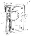
도 1은 본 발명에 따라, 이동 커버가 닫힌 위치에 있을 경우에, 인터넷 박스의 개략적 투시 정면도이다.
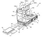
도 2는 커버가 열린 위치에 있는 도 1과 유사한 도면이다.
도 3은 커버가 열린 위치에 있는 도 1의 인터넷 박스의 개략적인 부분 분해도이다.
도 4는 도 1의 인터넷 박스를 벽에 고정한 후의 개략적인 사시도이다.
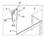
도 5는 벽을 향해 배치되도록 설계된 도 1의 인터넷 박스의 후면을 도시한다.
도 1 내지 도 5는 본 발명에 따른 일 실시예에 따라, 특히, 영업장, 주거지 등에 인터넷 접속을 제공하도록 설계된 전자 박스(B)(게이트웨이로도 불림)를 도시한다. 이들 도면이 도시하는 바와 같이, 전자 박스(B)는 직각 평행육면체의 형태이다. 다른 형태들(예를 들면, 타원형) 또한 당연히 예상될 수 있다.The accompanying drawings will provide a better understanding of how the invention may be implemented. In these drawings, like references refer to like elements.
1 is a schematic perspective front view of an Internet box when the moving cover is in a closed position, in accordance with the present invention;
Figure 2 is a view similar to Figure 1 with the cover in the open position;
Figure 3 is a schematic partial exploded view of the Internet box of Figure 1 with the cover in the open position.
4 is a schematic perspective view after fixing the Internet box of Fig. 1 to a wall; Fig.
Figure 5 shows the back side of the Internet box of Figure 1 designed to be placed against a wall.
1 to 5 illustrate an electronic box B (also referred to as a gateway) designed to provide an Internet connection to a business premises, a residential area, and the like, in accordance with an embodiment of the present invention. As shown in these figures, the electronic box B is in the form of a rectangular parallelepiped. Other shapes (e.g., elliptical) can also be expected of course.
본 발명은 인터넷 박스에 제한되지 않고, TV 디코더 박스(특히, 셋톱 박스)에도 적용될 수 있음이 용이하게 이해될 것이다. 더욱이, 인터넷 박스는 요구되고 적합한, 예를 들면, 정육면체인 임의의 다른 형태를 가질 수 있음은 명확하다.It will be readily understood that the present invention is not limited to the Internet box, but can also be applied to a TV decoder box (especially a set-top box). Moreover, it is clear that the Internet box may have any other form that is required and suitable, for example, a cube.
따라서, 관례상, 인터넷 박스(B)는 상기 박스(B)에 관련된 직교 축들(x, y, z)의 방향들(x, y 및 z)을 따라 각각 연장하는 깊이(p), 폭(l) 및 길이(L)에 의해 정의된다. 더욱이, 전/후, 좌/우 및 상/하의 개념은 방향들(x, y, 및 z)에 관련하여 정의된다: 축들(x, y, z)의 화살표의 방향은 뒤에서 앞으로, 좌에서 우로, 아래에서 위로의 경로를 각각 도시한다.Thus, by convention, the Internet box B has a depth p, a width l, and a width l, respectively, extending along the directions x, y, and z of the orthogonal axes x, y, ) And the length (L). Furthermore, the concept of before / after, left / right and up / down is defined in relation to directions (x, y, and z): the direction of the arrows of the axes (x, y, z) And a path from the bottom to the top, respectively.
실시예에서, 도 2 및 3에서 도시된 바와 같이, 인터넷 박스(B)는 In an embodiment, as shown in Figures 2 and 3, the Internet box B
박스(B)의 우측벽(2A) 상에 정의되고 인터넷 접속을 형성하기 위한 동축 접속 케이블(4)을 수용하도록 설계된 커넥터(3)가 배치되는 주 접속 영역(1A) - 일 예에서는 하나의 커넥터(3)만이 주 접속 영역(1A)에 도시되어 있지만, 변형예에서 이 영역은 몇몇의 유사 또는 상이한 커넥터를 포함할 수 있음 - ; 및A
박스(B)의 전면(6)에 있고, 전면(6)으로부터 후면(8)까지의 두께(p)로 박스(B)를 가로지르는 두 개의 오프닝(O)들을 포함하는 부착 영역(5)(도 5) - 각각의 오프닝(O)은, 예를 들면, 벽(9)에 고정된 관련 플러그(도시되지 않음)로 죄어지도록(screwed) 설계된(도 4) 해당 부착 스크루(7)를 수용할 수 있음(도 3) -An attachment region 5 (Fig. 1), which includes two openings O across the box B at the
을 포함한다..
인터넷 박스(B)는 또한, 이 박스의 우측 측면(2A) 상에 배치되고, 예를 들면, 이더넷, USB, RJ11 타입 등의 복수의 커넥터뿐만 아니라 전원 공급 커넥터를 포함하는 보조 접속 영역(1B)을 포함한다. 즉, 도시된 실시예에서, 주 접속 영역(1A 및 1B)은 박스(B)의 동일 벽 상에 인접하게 배치된다. 변형예에서, 이들은 인터넷 박스(B)의 상이한 벽 상에 배치될 수 있음을 이해할 수 있을 것이다.The Internet box B is also disposed on the
상기로부터, 주 접속 영역(1A) 및 부착 영역(5)이 박스(B)의 우측면(2A) 및정면(6)에 각각 배치되어 있으므로 - 이들 면(2A 및 6) 사이에 정의되는 각은 직각(90도)이거나 현저함 - , 주 접속 영역(1A) 및 부착 영역(5)은 연결되어 있지 않고 떨어져 있다는 것이 나타난다.From the above, since the
본 발명에 따라서, 도 1 내지 4에 도시된 바와 같이, 인터넷 박스(B)는 또한 편평한 벽(10A) 및 커버(10B)에 의해 형성되는 이동 커버(10)를 포함한다. 커버(10)는 적어도 닫힌 위치(도 1 및 도 4) 및 열린 위치(도 2 및 도 3)에 있을 수 있다. 닫힌 위치로부터 열린 위치로의 경로, 및 그 반대는 이중 화살표(F0)에 의해 기호적으로 도시된다(도 2).In accordance with the present invention, as shown in Figs. 1-4, the Internet box B also includes a moving
열린 위치는 닫힌 위치에 관련된 것과는 달리 커버(10)의 다수의 경사에 대응할 수 있음을 확인할 수 있을 것이다 (커버는 x 방향과 90도의 각을 가짐).It will be appreciated that the open position may correspond to multiple tilts of the
박스 길이(L) 부분에 있는 커버(10)의 좌측 일부를 따라 배치된 힌지(도시되지 않음)으로 인해, 커버(10)는 박스(B)의 나머지와 일체형을 유지한다. 변형예에서, 커버는 탈착될 수 있음을 이해할 것이다.The
커버(10B)는 (커버(10)가 닫힌 위치에 있는 경우) y 축을 따라 측면으로 연장하는 제1 연장부(10B.a)와 (닫힌 위치에서) x 축을 따라 깊이로 연장하는 제2 연장부(10B.b)에 의해 정의된다. 제1 및 제2 연장부 간에 정의된 각은 직각이거나 현저하다. 이 경우, 도 2 및 도 3에 도시된 바와 같이, 커버(10B)는 L자 형태를 갖는 프로필(z를 보는 방향에 따라 정의됨)을 특징으로 한다.The
제1 및 제2 연장부(10B.a 및 10B.b)의 상단 에지들은 상단 연결 벽(10B.c)에 의해 함께 연결되어 있다. 마찬가지로, 하단 연결 벽(10B.d)은 제1 및 제2 연장부(10B.a 및 10B.b)의 하단 에지에 연결된다.The upper edges of the first and second extensions 10B.a and 10B.b are connected together by an upper connecting wall 10B.c. Likewise, the lower connecting wall 10B.d is connected to the lower edges of the first and second extensions 10B.a and 10B.b.
또한, 도 2 및 도 3에 도시된 바와 같이, 각각의 상단 및 하단 연결 벽들(10B.c 및 10B.d) 내에, 커버(10)가 닫힌 위치에 있는 경우에, 하나 이상의 케이블(예에서 접속 케이블(4))이 통과할 수 있도록 컷아웃(cutout)(10B.e)이 제작되어 있다.Also, as shown in Figures 2 and 3, within each of the upper and lower connecting walls 10B.c and 10B.d, when the
이 경우에, 케이블(4)이 커넥터(3)에 삽입되면, 커버(10)의 닫힌 위치에서 커버(10B)는 케이블(4)의 접속 종단을 덮는다.In this case, when the
즉, 닫힌 위치(도 1 및 도 4)에서, 커버(10)는 편평한 벽(10A)으로 박스(B)의 정면(6)(및 부착 영역(5))과, 커버(10B)로 우측 벽(2A)의 일부(및 보다 구체적으로는 주 접속 영역(1A) - 보조 접속 영역(1B)은 덮지 않은 상태로 둠 - )를 덮는다. 따라서, 박스(B)의 최종 사용자는 커버(10)의 위치와는 독립적으로 보조 접속 영역(1B)의 모든 커넥터로의 액세스를 갖는다.1 and 4), the
일반적으로, 본 발명의 범위 내에서, 커버(10)가 닫힌 위치에 있는 경우에, 커버(10B)가 주 접속 영역(1A)의 접속 케이블(들)(예에서 접속 케이블(4))의 삽입 및/또는 제거 방향에 대략 수직인 면에 배치되는 벽(예에서 제2 연장(10B.b))을 포함하는 것이 바람직하다. 이 방법으로, 주 접속 영역(4)의 해당 커넥터들의 케이블(들)의 제거 및/또는 접속은 허용되지 않는다.In general, within the scope of the present invention, when the
이 경우에, 기술된 예에서, 커버(10)의 닫힌 위치에서, 커버(10B)의 제2 연장부(10B.b)는 특히 우측 벽(2A)에 평행하다.In this case, in the described example, in the closed position of the
더욱이, 도 1에 도시된 바와 같이, 커버(10B)는, 잠금 위치에서 커버(10)가 닫힌 위치에 유지될 수 있게 하는 키 잠금 시스템(11)으로 적합하다. 즉, 잠금 시스템(11)이 잠금 위치에 있고 커버(10)가 닫힌 위치에 있다면, 닫힌 위치로부터 열린 위치로 커버가 통과하는 것은 불가능하게 된다. 당연히, 임의의 다른 유형의, 예를 들면, 코드에 의한 잠금 시스템을 구상할 수 있다.Moreover, as shown in Fig. 1, the
이 경우에, 상기 설명의 결과, 닫힌 위치(도 1)에서 부착 영역(5) 및 주 접속 영역(1A)은 동시에 덮이게 되어 비승인된 사람(예를 들면, 최종 사용자)이 스크루(7)뿐만 아니라 접속 케이블(4)로 임의로 액세스하는 것을 막을 수 있다. 당연히, 스크루는 훅(hook), 못, 리벳(rivet) 등으로 교체될 수 있다는 것이 이해될 것이다.In this case, as a result of the above description, the
그러나, 커버(10)가 열린 위치(도 2 및 도 3)에 있다면, 접속 영역(1A) 및 부착 영역(5)은 각각 오퍼레이터 및/또는 최종 사용자에 의해 액세스될 수 있다.However, if the
더욱이, 커버(10)의 편평한 벽(10A)의 우상단 부분에 만들어진 직각 컷아웃(10C)은 인터넷 박스(B)의 다기능 명령 스크린(E)이 덮이지 않도록 하여, 커버(10)의 위치(닫힘 또는 열림)에 상관없이 외부로부터 액세스를 가능하게 한다.Moreover, the right-
또한, 편평한 벽(10A)은 인터넷 박스(B)의 오염을 막거나 적어도 감소시키기 위해 먼지에 대한 배리어 역할을 하도록 설계된 주변 에지(10A.a)를 포함한다. 주변 에지(10A.a)는 편평한 벽(10A)의 평면에 수직인 방향으로 연장한다.The
또한, 도 3에 도시된 바와 같이, 인터넷 박스(B)는, 하부 측벽(2C)의 레벨에서 제작되고 벽에 평행인 면으로 연장하는 슬롯(12)을 포함한다. 슬롯(12)은 내부 냉각 구성요소(도시되지 않음)에 의해 슬롯으로 유입되는 먼지가 박스(B)에 들어가는 것을 줄이거나 막는 먼지 필터(13)를 구비할 수 있다. 하부 측벽(2C)은 환기구(14)를 포함하여, 환기된 공기가 박스(B) 내부로부터 외부로 및 반대로 순환하는 것을 가능하게 한다. 이중 화살표(F1)(도 3)는 슬롯(12) 필터(13)의 삽입 및 추출 방향을 기호적으로 도시한다.Further, as shown in Fig. 3, the Internet box B includes a
또한, 하나 이상의 하우징이 박스(B) 내에 하위 부분에 배치될 수 있음을 확인될 것이다. 도시된 일 예에서(도 3 참조), 하부 측벽(2C)에 열린 두 개의 하우징(15)이 있다. 이들은 박스(B) 내에 하드 디스크(16) 및 CABLECARD 카드(등록 상표)(17)를 각각 삽입할 수 있다. 이중 화살표(F1)(도 3)는 하드 디스크(16) 및 카드(17)의 삽입 및 추출 방향을 기호적으로 도시한다.It will also be appreciated that one or more housings may be disposed in the lower portion within the box B. In the illustrated example (see Fig. 3), there are two
이 경우에, 하드 디스크(16) 및 카드(17)가 해당 하우징(15)에 삽입되면, 먼지 필터(13)가 관련 슬롯(12)에 삽입될 수 있다. 이 방법으로, 커버(10)가 닫힌 잠긴 위치에 있으면, 하드 디스크(16) 및 카드(17)의 추출은 더 이상 허용되지 않는다. 즉, 시스템(11)의 잠금 및 잠금해제를 제어하는 키를 가진 외부 오퍼레이터만이, (커버(10)가 열린 위치에 있다면) 슬롯(12)으로부터 필터(13)를 먼저 제거한 후에 하드 디스크(16) 및 카드(17)를 추출할 수 있다.In this case, when the
당연히, (예를 들면, 배터리를 지지하기 위한) 다른 하우징들이 박스(B) 내에, 특히 다른 벽들 상에 설계될 수 있다.Of course, other housings (for example for supporting the battery) may be designed in box B, especially on different walls.
더욱이, 도 5에 도시된 바와 같이, 박스(B)는, 주 접속 영역(1A) 및 보조 접속 영역(1B)에 접속된 케이블을 우측벽(2A)을 따라, 그리고 z 방향을 따라 배향하도록 설계된 탈착가능한 케이블 가이드(18)를 포함한다.5, the box B is designed to align the cables connected to the
케이블 가이드(18)는, 박스(B)에 맞는 경우, y 및 z 방향으로 정의된 평면에 연장된 전면 벽(18A), x 및 z 방향으로 정의된 평면에 연장된 측벽(18B)뿐만 아니라, x 및 y 방향으로 정의된 평면에 각각 속하는 두 개의 상부 및 하부 말단 벽(18C)에 의해 형성된다.The
오프닝(18C.a)은 각각의 말단 벽(18C)에 제작되어 (도 5에는 하나만 도시되어 있음), 케이블이 케이블 가이드(18)를 세로로 통과할 수 있게 한다.The opening 18C.a is made in each
각각의 이들 오프닝(18C.a)은, 예를 들면, 한 열의 헤어(hair)(또는 가요성 립(lip))의 형식인 먼지 보호 수단을 포함하여, 케이블 가이드(18) 내에 (그리고 따라서 주 접속 영역(1A) 및 보조 접속 영역(1B)의 커넥터 내에) 먼지의 유입을 차단하거나 적어도 제한할 수 있다.Each of these openings 18C.a may be provided in the cable guide 18 (and thus in the main lid 18c), including, for example, dust protection means in the form of a row of hair (or flexible lip) It is possible to shut off or at least restrict the inflow of dust in the connectors of the
케이블 가이드(18)는 x 방향에 따라 정의된 슬라이더 시스템(도 5에 도시되지 않음)에 의해 박스(B)에 고정될 수 있다.The
더욱이, 하우징(19)(도 2 및 도 5)은 박스(B)의 후면벽(8)에 배치될 수 있고, 이러한 방식으로 접속 케이블(4) 및 하나 이상의 다른 케이블의 (바람직하게는 말린) 일부를 수용한다. 이 하우징은 벽(9)에 박스(B)를 부착시킴으로써 닫혀진다.2 and 5) may be disposed on the
상술로부터, 변형예에서, 이동 커버는 단지 전면의 부착 영역을 덮고 전면을 더 이상 완전히 덮지 않도록 설계된 편평한 벽을 포함함을 이해할 것이다. 즉, 이 경우에, 커버의 편평한 벽은 스트립의 형태일 것이다.From the above, it will be appreciated from the foregoing that, in a variant, the moving cover only includes a flat wall designed to cover the front mounting area and not completely cover the front. That is, in this case, the flat wall of the cover will be in the form of a strip.
당연히, 본 발명은 상술된 실시예에 제한되지 않음을 이해하는 것은 용이하다.Of course, it is easy to understand that the present invention is not limited to the above-described embodiments.
Claims (11)
상기 주 접속 영역(1A)과 별개이고 상기 박스(B)의 다른 벽(6) 상에 정의된 부착 영역(5) - 상기 다른 벽(6)에는 상기 박스를 외부 지지대(9)에 부착하기 위한 수단(7)이 배치될 수 있음 - ; 및
상기 부착 수단이 고정되고(fitted) 상기 접속 케이블이 접속되는 경우에, 상기 주 접속 영역(1A) 및 상기 부착 영역(5)이 동시에 덮여서 상기 부착 수단들(7) 및 상기 외부 접속 케이블(4)로의 액세스를 차단하는 닫힌 위치, 및 상기 주 접속 영역(1A) 및 상기 부착 영역(5)이 액세스 가능한 열린 위치의 두 위치 중 적어도 하나에 있도록 구성된, 상기 박스(B)의 벽들(2A, 6)에 관련해 이동하는 이동부(10)
를 포함하는 것을 특징으로 하는 전자 박스.An electronic box in which at least one main connector (3) is arranged which includes a main connection area (1A) defined in one of the walls (2A) and designed to receive an externally connected cable (4) in the main connection area ,
An attachment region 5 which is separate from the main connection region 1A and which is defined on the other wall 6 of the box B and in which the other wall 6 is provided for attaching the box to the external support 9 Means (7) may be arranged; And
The main attachment region 1A and the attachment region 5 are covered at the same time so that the attachment means 7 and the external connection cable 4 (2A, 6B) of the box (B) configured to be in at least one of a closed position blocking access to the box (B) and an open position accessible to the attachment region The moving part 10,
And the electronic box.
상기 주 접속 영역(1A)과 별개이고 상기 주 접속 영역과 동일한 벽(2A) 상에 정의된 보조 접속 영역(1B)을 포함하고, 상기 이동부(10)가 점유한 위치에 관계없이 상기 보조 접속 영역(1B)이 액세스 가능한 상태로 있는 전자 박스.The method according to claim 1,
(1B) defined on a wall (2A) that is separate from the main connection region (1A) and is the same as the main connection region, and wherein the auxiliary connection region An electronic box in which the area (1B) is in an accessible state.
상기 주 접속 영역(1A) 및 보조 접속 영역(1B)이 인접한 전자 박스.3. The method of claim 2,
Wherein the main connection area (1A) and the auxiliary connection area (1B) are adjacent to each other.
상기 이동부(10)는
닫힌 위치에서 상기 부착 영역(5)을 덮도록 구성된 편평한 벽(10A), 및
닫힌 위치에서 상기 주 접속 영역(1A)을 덮도록 구성된, 상기 편평한 벽(10A)과 일체형인 커버(10B)를 포함하는 전자 박스.4. The method according to any one of claims 1 to 3,
The moving unit 10
A flat wall (10A) configured to cover the attachment area (5) in a closed position, and
And a cover (10B) integral with said flat wall (10A), configured to cover said main connection area (1A) in a closed position.
상기 커버(10B)는, 상기 이동부(10)가 상기 닫힌 위치에 있는 경우, 이 위치에서 상기 외부 접속 케이블(4)의 접속해제를 막을 수 있도록 하기 위해, 상기 외부 접속 케이블(4)을 상기 주 커넥터(3)로 삽입하는 방향에 완전히 수직으로 배치된 벽(10B.b)을 포함할 수 있는 전자 박스.5. The method of claim 4,
The cover 10B is provided with the external connecting cable 4 so that the external connecting cable 4 can be prevented from being disconnected at this position when the moving part 10 is in the closed position. And a wall (10B.b) disposed substantially perpendicular to the direction of insertion into the main connector (3).
상기 커버(10B)는, 잠금 시스템(11)이 잠긴 경우에, 상기 이동부(10)가 닫힌 위치에 유지되도록 하는 상기 잠금 시스템(11)을 포함하는 전자 박스.The method according to claim 4 or 5,
The cover (10B) comprises the locking system (11) for allowing the moving part (10) to be held in a closed position when the locking system (11) is locked.
상기 이동부(10)가 상기 열린 위치에 있는 경우에 해당 탈착가능한 주 모듈(13)이 삽입될 수 있는 적어도 하나의 하우징(12)을 포함하고, 상기 주 모듈(13)은 상기 이동부(10)가 상기 닫힌 위치에 있는 경우에 상기 이동부(10)에 의해 상기 주 하우징(12) 내부에 유지되는 전자 박스.7. The method according to any one of claims 1 to 6,
And at least one housing (12) into which the removable main module (13) can be inserted when the moving part (10) is in the open position, the main module (13) Is held inside the main housing (12) by the moving part (10) when the main housing (12) is in the closed position.
상기 이동부(10)가 상기 열린 위치에 있는 경우에 해당 탈착가능한 보조 모듈(16)이 삽입될 수 있는 적어도 하나의 보조 하우징(15)을 포함하고, 상기 보조 모듈(16)은 상기 이동부(10)가 상기 닫힌 위치에 있는 경우에 상기 이동부(13)에 의해 상기 보조 하우징(15) 내부에 유지되는 전자 박스.8. The method of claim 7,
And at least one auxiliary housing (15) into which the detachable auxiliary module (16) can be inserted when the moving part (10) is in the open position, the auxiliary module (16) 10) is held in the auxiliary housing (15) by the moving part (13) when the movable part (13) is in the closed position.
적어도 하나의 외부 접속 케이블(4)을 상기 박스(B)의 벽(2A)을 따라 배향하도록 설계된 탈착가능한 가이드(18)를 포함하는 전자 박스.9. The method according to any one of claims 1 to 8,
(18) designed to orient at least one external connecting cable (4) along the wall (2A) of the box (B).
적어도 부분적으로 하나 이상의 외부 접속 케이블(4)이 삽입될 수 있는 하우징(19)을 포함하는 전자 박스.10. The method according to any one of claims 1 to 9,
(19) into which at least one external connecting cable (4) can at least partly be inserted.
인터넷 및/또는 비디오 디코딩을 위한 액세스 박스에 대응하는 전자 박스.11. The method according to any one of claims 1 to 10,
An electronic box corresponding to an access box for internet and / or video decoding.
Applications Claiming Priority (2)
| Application Number | Priority Date | Filing Date | Title |
|---|---|---|---|
| FR1261965A FR2999371A1 (en) | 2012-12-12 | 2012-12-12 | ELECTRONIC HOUSING, IN PARTICULAR FOR ACCESSING THE INTERNET AND / OR FOR VIDEO DECODING |
| FR1261965 | 2012-12-12 |
Publications (1)
| Publication Number | Publication Date |
|---|---|
| KR20140076523A true KR20140076523A (en) | 2014-06-20 |
Family
ID=47833255
Family Applications (1)
| Application Number | Title | Priority Date | Filing Date |
|---|---|---|---|
| KR1020130154988A KR20140076523A (en) | 2012-12-12 | 2013-12-12 | Electronic box, particularly for internet access and/or for video decoding |
Country Status (7)
| Country | Link |
|---|---|
| US (1) | US9414509B2 (en) |
| EP (1) | EP2744312B1 (en) |
| JP (1) | JP2014120169A (en) |
| KR (1) | KR20140076523A (en) |
| CN (1) | CN103873898A (en) |
| BR (1) | BR102013030720A2 (en) |
| FR (1) | FR2999371A1 (en) |
Families Citing this family (3)
| Publication number | Priority date | Publication date | Assignee | Title |
|---|---|---|---|---|
| WO2019149596A1 (en) * | 2018-01-30 | 2019-08-08 | Philips Lighting Holding B.V. | A driver housing |
| US11122707B2 (en) | 2018-07-12 | 2021-09-14 | Arris Enterprises Llc | Raised pathway heat sink |
| CN113685092B (en) * | 2020-05-19 | 2022-09-06 | 富联精密电子(天津)有限公司 | Locking structure and server case with same |
Family Cites Families (15)
| Publication number | Priority date | Publication date | Assignee | Title |
|---|---|---|---|---|
| US5482232A (en) | 1993-06-21 | 1996-01-09 | Mirage Resorts, Incorporated | Apparatus and method for wall-mounted hardware system |
| DE9404470U1 (en) * | 1994-03-16 | 1994-05-11 | Siemens Nixdorf Inf Syst | Housing for data processing equipment |
| US5823646A (en) * | 1997-09-02 | 1998-10-20 | Siecor Corporation | Door assembly for optical hardware cabinet |
| FR2805357A1 (en) * | 2000-02-22 | 2001-08-24 | Philippe Jean Jack Gressier | Casing for microcomputer includes peripheral connections on top edge, and pivoting flaps retaining cables |
| US6443322B1 (en) * | 2000-10-19 | 2002-09-03 | Fujitsu Network Communications, Inc. | Wall mount enclosure having installation features for multiple separately-installed components |
| JP2005182454A (en) | 2003-12-19 | 2005-07-07 | Toshiba Corp | Electronic appliance |
| CN2715215Y (en) | 2004-07-02 | 2005-08-03 | 鸿富锦精密工业(深圳)有限公司 | Computer connector and cable protector |
| US7760984B2 (en) * | 2006-05-04 | 2010-07-20 | Adc Telecommunications, Inc. | Fiber distribution hub with swing frame and wrap-around doors |
| US20080120667A1 (en) * | 2006-11-17 | 2008-05-22 | Texas Instruments Incorporated | Hybrid mpeg/ip digital cable gateway device and architecture associated therewith |
| JP2008240439A (en) | 2007-03-28 | 2008-10-09 | Saxa Inc | Locking structure of case body |
| AU2009213051A1 (en) * | 2008-10-28 | 2010-05-13 | Adc Gmbh | Enclosure for housing splice trays |
| US20120137338A1 (en) * | 2009-08-07 | 2012-05-31 | Clearone Communications, Inc. | Decoder vesa mounting assembly |
| CN202285424U (en) * | 2011-10-25 | 2012-06-27 | 四川省迪特尔数字电视有限公司 | IPTV (Internet Protocol Television) set top box supporting remote updating and EPG (Electronic Program Guide) program searching |
| US8993886B2 (en) * | 2012-12-10 | 2015-03-31 | Amx Llc | Hardware casing with spring loaded friction fitting cover |
| US20130228368A1 (en) * | 2013-04-19 | 2013-09-05 | Tyco Electronics Raychem Bvba | Wall box and wall mounted plate with integrated ducts |
-
2012
- 2012-12-12 FR FR1261965A patent/FR2999371A1/en not_active Withdrawn
-
2013
- 2013-11-22 EP EP13194111.4A patent/EP2744312B1/en not_active Not-in-force
- 2013-11-28 BR BRBR102013030720-3A patent/BR102013030720A2/en not_active Application Discontinuation
- 2013-12-03 CN CN201310644178.5A patent/CN103873898A/en active Pending
- 2013-12-11 JP JP2013256053A patent/JP2014120169A/en not_active Withdrawn
- 2013-12-12 US US14/103,913 patent/US9414509B2/en active Active
- 2013-12-12 KR KR1020130154988A patent/KR20140076523A/en not_active Application Discontinuation
Also Published As
| Publication number | Publication date |
|---|---|
| JP2014120169A (en) | 2014-06-30 |
| CN103873898A (en) | 2014-06-18 |
| EP2744312A1 (en) | 2014-06-18 |
| US20140174817A1 (en) | 2014-06-26 |
| EP2744312B1 (en) | 2015-07-15 |
| FR2999371A1 (en) | 2014-06-13 |
| BR102013030720A2 (en) | 2014-09-02 |
| US9414509B2 (en) | 2016-08-09 |
Similar Documents
| Publication | Publication Date | Title |
|---|---|---|
| KR102099072B1 (en) | Shutter door assembly for an electrical panel | |
| US7579549B2 (en) | Protective device plate for an electrical box | |
| CA2592830C (en) | Universal recessed while-in-use box and cover | |
| RU2562958C2 (en) | Front panel for socket | |
| KR20140076523A (en) | Electronic box, particularly for internet access and/or for video decoding | |
| JP6836889B2 (en) | Electrical junction box and wire harness | |
| US8531828B2 (en) | Storage device carrier having a pivoting panel | |
| KR102286385B1 (en) | Enclosure for electrical installations | |
| JP5768262B2 (en) | Ventilation equipment | |
| JP4648300B2 (en) | Electronic equipment housing | |
| CA2925312A1 (en) | Low profile while-in-use electrical box and cover | |
| JP2003061229A (en) | Floor wiring implement | |
| JP2007287492A (en) | Embedded type electric-wiring connecting device | |
| JP7028848B2 (en) | Electrical junction box | |
| US10684067B2 (en) | Method for assembling camera assembly | |
| US10641543B2 (en) | Camera assembly and refrigerator employing same | |
| JPH01502154A (en) | Wall mounting system for data communication connectors | |
| JP5389094B2 (en) | Electronic device casing and amplifier including the same | |
| JP4218646B2 (en) | Floor wiring system | |
| JP6869805B2 (en) | cabinet | |
| US9748751B1 (en) | Electrical box assembly for angled recessed mounting of high and low voltage components | |
| JP2005143607A (en) | Game machine | |
| KR101165199B1 (en) | The desk assembly-type computer main body cabinet having a robbery prvention structure | |
| JP5904353B2 (en) | Outlet | |
| KR200358872Y1 (en) | Access floor panel |
Legal Events
| Date | Code | Title | Description |
|---|---|---|---|
| WITN | Application deemed withdrawn, e.g. because no request for examination was filed or no examination fee was paid |