KR20140061490A - Autonomous cleaning appliance - Google Patents
Autonomous cleaning appliance Download PDFInfo
- Publication number
- KR20140061490A KR20140061490A KR1020147008885A KR20147008885A KR20140061490A KR 20140061490 A KR20140061490 A KR 20140061490A KR 1020147008885 A KR1020147008885 A KR 1020147008885A KR 20147008885 A KR20147008885 A KR 20147008885A KR 20140061490 A KR20140061490 A KR 20140061490A
- Authority
- KR
- South Korea
- Prior art keywords
- robot
- chassis
- separating device
- axis
- air inlet
- Prior art date
Links
Images


Classifications
-
- A—HUMAN NECESSITIES
- A47—FURNITURE; DOMESTIC ARTICLES OR APPLIANCES; COFFEE MILLS; SPICE MILLS; SUCTION CLEANERS IN GENERAL
- A47L—DOMESTIC WASHING OR CLEANING; SUCTION CLEANERS IN GENERAL
- A47L5/00—Structural features of suction cleaners
- A47L5/12—Structural features of suction cleaners with power-driven air-pumps or air-compressors, e.g. driven by motor vehicle engine vacuum
- A47L5/22—Structural features of suction cleaners with power-driven air-pumps or air-compressors, e.g. driven by motor vehicle engine vacuum with rotary fans
- A47L5/28—Suction cleaners with handles and nozzles fixed on the casings, e.g. wheeled suction cleaners with steering handle
- A47L5/30—Suction cleaners with handles and nozzles fixed on the casings, e.g. wheeled suction cleaners with steering handle with driven dust-loosening tools, e.g. rotating brushes
-
- A—HUMAN NECESSITIES
- A47—FURNITURE; DOMESTIC ARTICLES OR APPLIANCES; COFFEE MILLS; SPICE MILLS; SUCTION CLEANERS IN GENERAL
- A47L—DOMESTIC WASHING OR CLEANING; SUCTION CLEANERS IN GENERAL
- A47L9/00—Details or accessories of suction cleaners, e.g. mechanical means for controlling the suction or for effecting pulsating action; Storing devices specially adapted to suction cleaners or parts thereof; Carrying-vehicles specially adapted for suction cleaners
- A47L9/02—Nozzles
-
- A—HUMAN NECESSITIES
- A47—FURNITURE; DOMESTIC ARTICLES OR APPLIANCES; COFFEE MILLS; SPICE MILLS; SUCTION CLEANERS IN GENERAL
- A47L—DOMESTIC WASHING OR CLEANING; SUCTION CLEANERS IN GENERAL
- A47L9/00—Details or accessories of suction cleaners, e.g. mechanical means for controlling the suction or for effecting pulsating action; Storing devices specially adapted to suction cleaners or parts thereof; Carrying-vehicles specially adapted for suction cleaners
- A47L9/10—Filters; Dust separators; Dust removal; Automatic exchange of filters
- A47L9/106—Dust removal
-
- A—HUMAN NECESSITIES
- A47—FURNITURE; DOMESTIC ARTICLES OR APPLIANCES; COFFEE MILLS; SPICE MILLS; SUCTION CLEANERS IN GENERAL
- A47L—DOMESTIC WASHING OR CLEANING; SUCTION CLEANERS IN GENERAL
- A47L9/00—Details or accessories of suction cleaners, e.g. mechanical means for controlling the suction or for effecting pulsating action; Storing devices specially adapted to suction cleaners or parts thereof; Carrying-vehicles specially adapted for suction cleaners
- A47L9/10—Filters; Dust separators; Dust removal; Automatic exchange of filters
- A47L9/14—Bags or the like; Rigid filtering receptacles; Attachment of, or closures for, bags or receptacles
- A47L9/1409—Rigid filtering receptacles
-
- A—HUMAN NECESSITIES
- A47—FURNITURE; DOMESTIC ARTICLES OR APPLIANCES; COFFEE MILLS; SPICE MILLS; SUCTION CLEANERS IN GENERAL
- A47L—DOMESTIC WASHING OR CLEANING; SUCTION CLEANERS IN GENERAL
- A47L9/00—Details or accessories of suction cleaners, e.g. mechanical means for controlling the suction or for effecting pulsating action; Storing devices specially adapted to suction cleaners or parts thereof; Carrying-vehicles specially adapted for suction cleaners
- A47L9/10—Filters; Dust separators; Dust removal; Automatic exchange of filters
- A47L9/16—Arrangement or disposition of cyclones or other devices with centrifugal action
-
- A—HUMAN NECESSITIES
- A47—FURNITURE; DOMESTIC ARTICLES OR APPLIANCES; COFFEE MILLS; SPICE MILLS; SUCTION CLEANERS IN GENERAL
- A47L—DOMESTIC WASHING OR CLEANING; SUCTION CLEANERS IN GENERAL
- A47L9/00—Details or accessories of suction cleaners, e.g. mechanical means for controlling the suction or for effecting pulsating action; Storing devices specially adapted to suction cleaners or parts thereof; Carrying-vehicles specially adapted for suction cleaners
- A47L9/28—Installation of the electric equipment, e.g. adaptation or attachment to the suction cleaner; Controlling suction cleaners by electric means
-
- A—HUMAN NECESSITIES
- A47—FURNITURE; DOMESTIC ARTICLES OR APPLIANCES; COFFEE MILLS; SPICE MILLS; SUCTION CLEANERS IN GENERAL
- A47L—DOMESTIC WASHING OR CLEANING; SUCTION CLEANERS IN GENERAL
- A47L2201/00—Robotic cleaning machines, i.e. with automatic control of the travelling movement or the cleaning operation
Landscapes
- Engineering & Computer Science (AREA)
- Mechanical Engineering (AREA)
- Electric Vacuum Cleaner (AREA)
- Electric Suction Cleaners (AREA)
- Filters For Electric Vacuum Cleaners (AREA)
- Nozzles For Electric Vacuum Cleaners (AREA)
Abstract
An automatic vacuum cleaner comprising: a body defining a first axis and having a dirty air inlet, a clean air outlet, a body for receiving an airflow path between the dirty air inlet and the clean air outlet, and a body between the dirty air inlet and the clean air outlet Wherein the separating device defines a second axis and the separating device is oriented such that the second axis is substantially parallel to the first axis of the body, Wherein a part of the protruding portion protrudes from a front portion of the main body of the vacuum cleaner.
Description
The present invention relates to a self-cleaning device, more particularly an automatic or 'robotic' vacuum cleaner.
Movable robots are becoming more and more commonplace and are used in a variety of areas such as space exploration, mowing and floor cleaning. In the last decade there has been a very rapid development in the field of robotic floor cleaning equipment, especially vacuum cleaners, whose primary purpose is to navigate areas of the home or office, automatically unseen while cleaning the floor.
A known automatic guided vacuum cleaner is illustrated in EP 0803224, which includes a chassis supporting a housing with a cover and a front portion movable relative to the chassis and forming a part of the collision detection system. The cover is fixed to the housing, and the housing is continued into the intermediate wall immediately after the front portion. The intermediate wall is continuous into the handle for the user to carry the vacuum cleaner.
Although common in robot vacuum cleaners, the chassis includes a cleaner head having a brush bar, a fan / motor unit, a dust container, a rechargeable battery, a drive motor for driving radially positioned wheels, and an additional drive motor for driving the brush bar . In addition, the vacuum cleaner has an electronic control system connected as needed with the drive motor and a sensing system for guiding and controlling the movement of the vacuum cleaner on the floor. In order to collect dust removed from the floor surface, the vacuum cleaner has a bag-shaped dust container which is located in a chamber defined by the intermediate wall described above. As can be appreciated, this dust container is housed within the outer cover of the vacuum cleaner, making it inconvenient for the user to access it.
SUMMARY OF THE INVENTION In view of this background, the present invention has been developed and, to achieve this object, the present invention is directed to a fuel cell having a cylindrical axis and having a dirty air inlet, a clean air outlet, a cylindrical body for receiving an airflow path between the dirty air inlet and the clean air outlet, And a separation device disposed within the airflow path between the dirty air inlet and the clean air outlet. The separating device comprises a cylindrical container having an axis, wherein the separating device is oriented so that its axis is substantially parallel to the cylindrical axis of the body, wherein a portion of the separating device protrudes from a front portion of the body of the vacuum cleaner.
Therefore, in the present case, the separating device is in an upright orientation because its axis is substantially parallel to the cylindrical axis of the body of the cleaner, and furthermore the separating device is located in front of the cleaner and partially exposed. This allows the user to easily access the separating device when it is necessary to empty the separating device, and its upright orientation makes it easy to grasp by the user. In addition, the position of the separating device means that the vacuum cleaner provides an elastic bumper for obstacles that may be encountered while moving around the room. Because the separator is a relatively large component without any relatively elaborate electronic devices, it provides some degree of collision protection to the vacuum cleaner and also provides some degree of protection against obstacles that the vacuum cleaner may collide with.
In order to provide a vacuum cleaner with a low profile and also a " clean " top surface, the body may define a flat top surface, and the detachment device may also define a flat top surface coplanar with the flat top surface of the body. This configuration is beneficial not only in contributing to the low profile of the vacuum cleaner, but also in the situation where a navigation sensor can be mounted on the top surface of the body, so that such a sensor can be provided with a 360 < RTI ID = 0.0 > Provide a field of view.
To improve the fitability of the detachment device within the body, the body may include a portion of a partially cylindrical docking bay capable of receiving the detachment device, the docking bay portion having a shape complementary to the outer profile of the detachment device I have. For this purpose, the docking bay portion may be defined in part by the body portion, and in part by the cover portion, and the cover portion may define the first and second arm portions located on opposite sides of the separation device have. The body portion may include a platform portion that supports a lower end of the detachment device.
The body portion may include an air flow generator for generating an air flow along an air flow path from the dirty air inlet to the clean air outlet.
The body portion may be mounted on the chassis, the chassis including traction means for supporting the body on the surface and a cleaner head defining the dirty air inlet, wherein the body portion is configured to be movable relative to the chassis And the sensing means is provided for sensing the relative movement to provide a suitable signal to the drive control system of the vacuum cleaner.
In another arrangement, there is provided an automatic surface treatment instrument comprising a body and a handle that is movable between a position accommodated relative to the body and a deployed position the user can grasp to lift the device from the floor. When in the accepted position, the handle engages the component of the device to prevent access to or removal of the component of the device.
The handle therefore provides multiple functions, for example, allowing the user to carry and carry the device, as well as acting as a storage device for other components of the machine and / or as a movable access door. This is useful in various types of surface treatment machines, such as floor polishers and sweepers, but has particular application in the field of mobile robotic vacuum cleaners.
The body of the device may be substantially circular in the planar profile and advantageously the handle may be pivoted about the first and second journals provided on opposite points in the radial direction on the body.
In the deployed position, the handle can extend in a plane that is substantially perpendicular to the longitudinal axis of the device, and in this way the device is free to assume an orientation parallel to the bottom surface when the user is carrying it.
The additional component of the device may be a detachable panel of the device and the handle of the received position may engage at least a portion of the detachable panel so that the user can not remove it from the device. In one embodiment, the removable panel comprises a filter element located in the exhaust outlet of the device, and the panel is detachable so that the user can periodically clean the filter element. More specifically, in the received position, the handle can be seated inside the channel defined by the periphery of the device, and the channel is at least partially defined by the removable panel.
Alternatively or additionally, the additional component may be one or more electrical sockets and the handle of the received position may be defined within the channel to shield at least a portion of the socket or each socket to prevent access by the user .
In another aspect, the present invention resides in an automatic surface treatment apparatus comprising a body defining an outer circumferential surface and a handle movable relative to the body between a received position and a deployed position that the user can grasp to lift the apparatus from the floor In which the handle extends in a plane lying at an angle to the longitudinal axis of the device and the handle is located in contact with at least a part of the peripheral surface of the device when in the accommodated position.
Advantageously, in the accommodated position, this arrangement coincides with the peripheral surface of the device, so that it can be easily accessible for the user to carry the device while maintaining a circular outer profile, thereby improving portability, And provides a transport arrangement to the automatic device that does not protrude to the user during normal operation of the device.
BRIEF DESCRIPTION OF THE DRAWINGS The accompanying drawings, which are included to provide a further understanding of the invention, will now be described by way of example only.
1 is a front perspective view of a device according to an embodiment of the present invention;
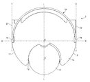
Figure 2 is a top view of the device of Figure 1;
Figure 3 is a bottom view of the device of Figure 1;
Figure 4 is an exploded perspective view showing the main assembly of the device of the present invention;
Figure 5 is a rear perspective view of the device of the present invention in a position where the handle is received;
Figure 6 is a rear perspective view of the device of the present invention in a position where the handle is deployed;
7 is a rear perspective view of the device of the present invention in which the handle is deployed and the detachable panel is removed;
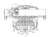
8 is a front view of the chassis of the movable robot;
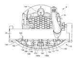
9 is a bottom view of the main body of the movable robot;
10 is a rear view of the main body of the movable robot;
11A, 11B, 11C and 11D are schematic diagrams of the robot in various ' crashes 'situations;
12 is a schematic view of the system of the device.
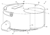
1, 2, 3 and 4 of the drawings, an automatic surface treatment apparatus in the form of a robot vacuum cleaner 2 (hereinafter referred to as a robot) has a body including four main assemblies: a
In the present specification, the terms 'front' and 'rear' relating to the robot will be used in the forward and reverse directions of the robot during operation, and the
The
3 and 4, the
The pair of
The relatively
The vacuum
The lower side of the
In this embodiment, the
The
The waste drawn into the
The
It should be noted that in this embodiment the separating
When the separating
The dirty air is sucked by the air flow generator through the
Since the
The
1, the partially
The opposing portion of the
The separating
A further advantage is that the separating
The
The carrying
6 and 7 show that the
In addition to being able to snugly fit within a portion of the
As clearly shown in Figures 5, 6 and 7, the rear portion of the
The
The upper edge of the
In the illustrated embodiment, the panel comprises a
In addition to providing a holding function for the
8, 9 and 10, there is shown a method of collecting information on how the
The front and rear engaging means are arranged so that the
8, the front engaging means comprises a racetrack / stadium, which is defined within the front part of the
The engagement means also includes a complementary structure on the front portion of the
The front portion of the
The rear engaging means restricts the movement of the
Both sides of the collision detecting means include body supporting means, and since both body supporting means are the same, only one will be described for the sake of simplicity. The body support means includes a sleeve-shaped tubular support member (152) that is seated within a dish-shaped recess (154) defined within the chassis (4). In this embodiment, the dish-shaped
The
The
The
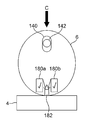
The collision detection means 148 also includes a switch means 180 for detecting the relative movement of the
The
Operations of the
Figure 11A shows the relative positions of the
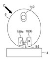
Fig. 11 (b) shows the
Alternatively, if an obstacle collides to the right as indicated by the arrow C in Fig. 11C, the
Conversely, when the
Only one of the
Since the
Since the
The sensing means has been described as including a snap-action switch disposed on both sides of the wedge-shaped actuator,
The body makes it possible to operate the switch conveniently when moving in a linear direction (with both switches operating at the same time) or in an angular direction (one switch operating before another switch). However, those skilled in the art will appreciate that other switch mechanisms are also possible, for example, non-contact switches such as a light-gate switch or a magnetic / Hall effect switch.
In operation, the
The
The
Finally, a power input is provided from the
Many variations are possible without departing from the inventive concept. For example, while the
Further, although the
In the above embodiment, the
Claims (11)
Wherein the body defines a substantially flat upper surface and the separation device defines a substantially flat upper surface coplanar with an upper surface of the body.
And a docking bay capable of receiving the separating device therein, wherein the docking bay portion has a shape that replenishes the external profile of the separating device.
Wherein the body includes a platform portion supporting a lower end of the separating device.
Wherein the body defines first and second arm portions located on opposite sides of the separation device.
Wherein the first and second arm portions are sensor housings.
Wherein the main body includes an air flow generator for generating an air flow along the air flow path from the dirty air inlet to the clean air outlet.
Wherein the body includes a chassis, the chassis including traction means for supporting the body on a surface, and a cleaner head defining the dirty air inlet.
Wherein the body is substantially cylindrical.
Wherein the separating device is substantially cylindrical.
Applications Claiming Priority (3)
| Application Number | Priority Date | Filing Date | Title |
|---|---|---|---|
| GB1115607.2 | 2011-09-09 | ||
| GB1115607.2A GB2494446B (en) | 2011-09-09 | 2011-09-09 | Autonomous cleaning appliance |
| PCT/GB2012/052060 WO2013034885A1 (en) | 2011-09-09 | 2012-08-22 | Autonomous cleaning appliance |
Publications (2)
| Publication Number | Publication Date |
|---|---|
| KR20140061490A true KR20140061490A (en) | 2014-05-21 |
| KR101571379B1 KR101571379B1 (en) | 2015-11-24 |
Family
ID=44908316
Family Applications (1)
| Application Number | Title | Priority Date | Filing Date |
|---|---|---|---|
| KR1020147008885A KR101571379B1 (en) | 2011-09-09 | 2012-08-22 | Autonomous cleaning appliance |
Country Status (8)
| Country | Link |
|---|---|
| US (1) | US9999328B2 (en) |
| EP (1) | EP2753224B1 (en) |
| JP (2) | JP5935215B2 (en) |
| KR (1) | KR101571379B1 (en) |
| CN (1) | CN102987983B (en) |
| ES (1) | ES2611356T3 (en) |
| GB (1) | GB2494446B (en) |
| WO (1) | WO2013034885A1 (en) |
Cited By (11)
| Publication number | Priority date | Publication date | Assignee | Title |
|---|---|---|---|---|
| WO2017200345A1 (en) * | 2016-05-20 | 2017-11-23 | 엘지전자 주식회사 | Robot cleaner |
| WO2017200349A1 (en) * | 2016-05-20 | 2017-11-23 | 엘지전자 주식회사 | Robot cleaner |
| US10342405B2 (en) | 2016-05-20 | 2019-07-09 | Lg Electronics Inc. | Autonomous cleaner |
| US10342400B2 (en) | 2016-05-20 | 2019-07-09 | Lg Electronics Inc. | Autonomous cleaner |
| AU2017266808B2 (en) * | 2016-05-20 | 2019-08-15 | Lg Electronics Inc. | Robot cleaner |
| US10398276B2 (en) | 2016-05-20 | 2019-09-03 | Lg Electronics Inc. | Autonomous cleaner |
| US10420448B2 (en) | 2016-05-20 | 2019-09-24 | Lg Electronics Inc. | Autonomous cleaner |
| US10441128B2 (en) | 2016-05-20 | 2019-10-15 | Lg Electronics Inc. | Autonomous cleaner |
| US10463212B2 (en) | 2016-05-20 | 2019-11-05 | Lg Electronics Inc. | Autonomous cleaner |
| US10463221B2 (en) | 2016-05-20 | 2019-11-05 | Lg Electronics Inc. | Autonomous cleaner |
| US10481611B2 (en) | 2016-05-20 | 2019-11-19 | Lg Electronics Inc. | Autonomous cleaner |
Families Citing this family (62)
| Publication number | Priority date | Publication date | Assignee | Title |
|---|---|---|---|---|
| AU349618S (en) | 2012-09-24 | 2013-07-04 | Dyson Technology Ltd | A vacuum cleaner |
| CN110448222A (en) | 2013-04-15 | 2019-11-15 | 伊莱克斯公司 | Robotic vacuum cleaner |
| KR20150141979A (en) | 2013-04-15 | 2015-12-21 | 악티에볼라겟 엘렉트로룩스 | Robotic vacuum cleaner with protruding sidebrush |
| US9946263B2 (en) | 2013-12-19 | 2018-04-17 | Aktiebolaget Electrolux | Prioritizing cleaning areas |
| US9811089B2 (en) | 2013-12-19 | 2017-11-07 | Aktiebolaget Electrolux | Robotic cleaning device with perimeter recording function |
| JP6638987B2 (en) | 2013-12-19 | 2020-02-05 | アクチエボラゲット エレクトロルックス | Adaptive speed control of rotating side brush |
| US10045675B2 (en) | 2013-12-19 | 2018-08-14 | Aktiebolaget Electrolux | Robotic vacuum cleaner with side brush moving in spiral pattern |
| WO2015090399A1 (en) | 2013-12-19 | 2015-06-25 | Aktiebolaget Electrolux | Robotic cleaning device and method for landmark recognition |
| KR102099495B1 (en) | 2013-12-19 | 2020-04-09 | 에이비 엘렉트로룩스 | Sensing climb of obstacle of a robotic cleaning device |
| EP3084540B1 (en) | 2013-12-19 | 2021-04-14 | Aktiebolaget Electrolux | Robotic cleaning device and operating method |
| EP3357393B1 (en) * | 2013-12-20 | 2021-09-29 | Aktiebolaget Electrolux | Autonomous cleaner |
| CN105848545B (en) | 2013-12-20 | 2019-02-19 | 伊莱克斯公司 | Dust receptacle |
| ES2681802T3 (en) | 2014-07-10 | 2018-09-17 | Aktiebolaget Electrolux | Method to detect a measurement error in a robotic cleaning device |
| AU360825S (en) | 2014-08-28 | 2015-03-30 | Dyson Technology Ltd | Vacuum cleaner |
| AU360829S (en) | 2014-08-28 | 2015-03-30 | Dyson Technology Ltd | Vacuum cleaner |
| AU360807S (en) | 2014-08-28 | 2015-03-26 | Dyson Technology Ltd | Vacuum cleaner |
| AU360831S (en) | 2014-08-28 | 2015-03-30 | Dyson Technology Ltd | Vacuum cleaner |
| AU360979S (en) | 2014-08-28 | 2015-04-08 | Dyson Technology Ltd | Vacuum cleaner |
| AU360827S (en) | 2014-08-28 | 2015-03-30 | Dyson Technology Ltd | Vacuum cleaner |
| AU360824S (en) | 2014-08-28 | 2015-03-30 | Dyson Technology Ltd | Vacuum cleaner |
| CN106659344B (en) | 2014-09-08 | 2019-10-25 | 伊莱克斯公司 | Robotic vacuum cleaner |
| CN106659345B (en) | 2014-09-08 | 2019-09-03 | 伊莱克斯公司 | Robotic vacuum cleaner |
| CN104188598B (en) * | 2014-09-15 | 2016-09-07 | 湖南格兰博智能科技有限责任公司 | A kind of automatic floor cleaning machine device people |
| KR101509737B1 (en) * | 2014-10-27 | 2015-04-07 | 주식회사코네트인더스트리 | Clean-nozzle assembly and vacuum cleaner |
| US10877484B2 (en) | 2014-12-10 | 2020-12-29 | Aktiebolaget Electrolux | Using laser sensor for floor type detection |
| US10986972B2 (en) * | 2014-12-12 | 2021-04-27 | Techtronic Industries Co. Ltd. | Battery powered vacuum cleaner |
| CN107072454A (en) | 2014-12-12 | 2017-08-18 | 伊莱克斯公司 | Side brush and robot cleaner |
| CN106998984B (en) | 2014-12-16 | 2021-07-27 | 伊莱克斯公司 | Cleaning method for a robotic cleaning device |
| WO2016165772A1 (en) | 2015-04-17 | 2016-10-20 | Aktiebolaget Electrolux | Robotic cleaning device and a method of controlling the robotic cleaning device |
| JP6736831B2 (en) | 2015-09-03 | 2020-08-05 | アクチエボラゲット エレクトロルックス | Robot cleaning device system, method for controlling cleaning device, computer program and computer program product |
| US10368711B1 (en) * | 2016-03-03 | 2019-08-06 | AI Incorporated | Method for developing navigation plan in a robotic floor-cleaning device |
| JP6576858B2 (en) * | 2016-03-10 | 2019-09-18 | 日立グローバルライフソリューションズ株式会社 | Autonomous electric vacuum cleaner |
| EP3430424B1 (en) | 2016-03-15 | 2021-07-21 | Aktiebolaget Electrolux | Robotic cleaning device and a method at the robotic cleaning device of performing cliff detection |
| CN109068908B (en) | 2016-05-11 | 2021-05-11 | 伊莱克斯公司 | Robot cleaning device |
| EP3459420B1 (en) | 2016-05-20 | 2021-03-17 | LG Electronics Inc. -1- | Robot cleaner |
| EP4201289A3 (en) | 2016-05-20 | 2023-07-26 | LG Electronics, Inc. | Robot cleaner |
| KR101878675B1 (en) | 2016-05-20 | 2018-07-18 | 엘지전자 주식회사 | Robot cleaner |
| USD813475S1 (en) | 2016-06-01 | 2018-03-20 | Milwaukee Electric Tool Corporation | Handheld vacuum cleaner |
| USD833094S1 (en) * | 2016-07-27 | 2018-11-06 | Lg Electronics Inc. | Dust canister for robot vacuum cleaner |
| JP7063534B2 (en) * | 2016-10-13 | 2022-05-09 | 日立グローバルライフソリューションズ株式会社 | Self-propelled electric vacuum cleaner |
| CN207979621U (en) * | 2017-01-17 | 2018-10-19 | 美国iRobot公司 | Mobile clean robot |
| JP6981005B2 (en) * | 2017-01-24 | 2021-12-15 | 三菱電機株式会社 | Cyclone separator and vacuum cleaner |
| KR20220025250A (en) | 2017-06-02 | 2022-03-03 | 에이비 엘렉트로룩스 | Method of detecting a difference in level of a surface in front of a robotic cleaning device |
| CN111093447B (en) | 2017-09-26 | 2022-09-02 | 伊莱克斯公司 | Movement control of a robotic cleaning device |
| CN107625490A (en) * | 2017-11-03 | 2018-01-26 | 重庆众誉材工科技有限公司 | A kind of floor cleaning machine in factory |
| US11140820B2 (en) * | 2018-04-06 | 2021-10-12 | Lg Electronics Inc. | Lawn mower robot |
| US11166409B2 (en) | 2018-04-06 | 2021-11-09 | Lg Electronics Inc. | Lawn mower robot |
| EP3560312B1 (en) | 2018-04-06 | 2021-10-20 | LG Electronics Inc. | Lawn mower robot |
| EP3549426B1 (en) * | 2018-04-06 | 2021-09-08 | LG Electronics Inc. | Lawn mower robot |
| EP3549425B1 (en) | 2018-04-06 | 2021-08-04 | LG Electronics Inc. | Lawn mower robot |
| EP3549424B1 (en) | 2018-04-06 | 2022-01-05 | Lg Electronics Inc. | Lawn mower robot |
| EP3549427B1 (en) | 2018-04-06 | 2021-09-01 | LG Electronics Inc. | Lawn mower robot |
| EP3549423B1 (en) * | 2018-04-06 | 2021-06-16 | Lg Electronics Inc. | Lawn mower robot |
| USD936719S1 (en) * | 2019-02-20 | 2021-11-23 | Lg Electronics Inc. | Home hub robot |
| US20220142438A1 (en) * | 2019-03-11 | 2022-05-12 | Midea Robozone Technology Co., Ltd. | Detection assembly, robotic vacuum cleaner, and walking floor status detection method and control method for robotic vacuum cleaner |
| UA41383S (en) * | 2019-03-18 | 2020-04-27 | Бейцзін Сяомі Мо | CLEANING DEVICE |
| DE102019211044B4 (en) * | 2019-07-25 | 2024-01-18 | BSH Hausgeräte GmbH | Surface care robots |
| USD940771S1 (en) * | 2019-08-15 | 2022-01-11 | Beijing Xiaomi Mobile Software Co., Ltd. | Robot vacuum cleaner |
| IL281841B2 (en) * | 2021-03-25 | 2023-04-01 | Cohen Assaf | A caterpillar apparatus for moving along a surface |
| CN114601374A (en) * | 2020-12-25 | 2022-06-10 | 北京石头世纪科技股份有限公司 | Cleaning robot |
| GB2610793B (en) * | 2021-01-22 | 2023-09-13 | Dyson Technology Ltd | Autonomous surface treatment apparatus |
| DE102021212384A1 (en) | 2021-11-03 | 2023-05-04 | BSH Hausgeräte GmbH | vacuum cleaning robot |
Family Cites Families (38)
| Publication number | Priority date | Publication date | Assignee | Title |
|---|---|---|---|---|
| US4782550A (en) * | 1988-02-12 | 1988-11-08 | Von Schrader Company | Automatic surface-treating apparatus |
| US5646494A (en) * | 1994-03-29 | 1997-07-08 | Samsung Electronics Co., Ltd. | Charge induction apparatus of robot cleaner and method thereof |
| SE509317C2 (en) | 1996-04-25 | 1999-01-11 | Electrolux Ab | Nozzle arrangement for a self-propelled vacuum cleaner |
| US5926909A (en) * | 1996-08-28 | 1999-07-27 | Mcgee; Daniel | Remote control vacuum cleaner and charging system |
| GB2344888A (en) * | 1998-12-18 | 2000-06-21 | Notetry Ltd | Obstacle detection system |
| GB2344900A (en) | 1998-12-18 | 2000-06-21 | Notetry Ltd | Robotic floor cleaning device with obstacle detection |
| GB2344745B (en) * | 1998-12-18 | 2002-06-05 | Notetry Ltd | Vacuum cleaner |
| GB9917232D0 (en) * | 1999-07-23 | 1999-09-22 | Notetry Ltd | Method of operating a floor cleaning device |
| GB2355391A (en) * | 1999-10-20 | 2001-04-25 | Notetry Ltd | Cyclonic vacuum cleaner with a horizontal, or substantially horizontal, separator |
| US6481515B1 (en) * | 2000-05-30 | 2002-11-19 | The Procter & Gamble Company | Autonomous mobile surface treating apparatus |
| CN1271967C (en) * | 2001-03-16 | 2006-08-30 | 幻影自动化机械公司 | Automatic mobile box vacuum cleaner |
| JP3909576B2 (en) | 2002-01-30 | 2007-04-25 | 東芝テック株式会社 | Electric vacuum cleaner |
| JP2003225184A (en) * | 2002-01-31 | 2003-08-12 | Toshiba Tec Corp | Cleaning device |
| US7210192B2 (en) * | 2002-05-08 | 2007-05-01 | Matsushita Electric Industrial Co., Ltd. | Vacuum cleaner having a slanted pedestal |
| KR100468107B1 (en) * | 2002-10-31 | 2005-01-26 | 삼성광주전자 주식회사 | Robot cleaner system having external charging apparatus and method for docking with the same apparatus |
| KR100478681B1 (en) * | 2003-07-29 | 2005-03-25 | 삼성광주전자 주식회사 | an robot-cleaner equipped with floor-disinfecting function |
| US7424766B2 (en) * | 2003-09-19 | 2008-09-16 | Royal Appliance Mfg. Co. | Sensors and associated methods for controlling a vacuum cleaner |
| US7603744B2 (en) * | 2004-04-02 | 2009-10-20 | Royal Appliance Mfg. Co. | Robotic appliance with on-board joystick sensor and associated methods of operation |
| US7617557B2 (en) * | 2004-04-02 | 2009-11-17 | Royal Appliance Mfg. Co. | Powered cleaning appliance |
| JP2006020936A (en) * | 2004-07-09 | 2006-01-26 | Funai Electric Co Ltd | Self-traveling vacuum cleaner and suspension structure |
| KR100595571B1 (en) * | 2004-09-13 | 2006-07-03 | 엘지전자 주식회사 | Robot cleaner |
| KR100661339B1 (en) * | 2005-02-24 | 2006-12-27 | 삼성광주전자 주식회사 | Automatic cleaning apparatus |
| JP2006296697A (en) * | 2005-04-20 | 2006-11-02 | Figla Co Ltd | Cleaning robot |
| US7389166B2 (en) * | 2005-06-28 | 2008-06-17 | S.C. Johnson & Son, Inc. | Methods to prevent wheel slip in an autonomous floor cleaner |
| US7770253B2 (en) * | 2005-12-10 | 2010-08-10 | Lg Electronics Inc. | Vacuum cleaner with removable dust collector, and methods of operating the same |
| KR20070074147A (en) * | 2006-01-06 | 2007-07-12 | 삼성전자주식회사 | Cleaner system |
| KR101250154B1 (en) * | 2006-02-28 | 2013-04-04 | 엘지전자 주식회사 | Vacuum Cleaner |
| KR101250077B1 (en) * | 2006-04-04 | 2013-04-02 | 엘지전자 주식회사 | Dust collecting unit of vacuum cleaner |
| US8417383B2 (en) * | 2006-05-31 | 2013-04-09 | Irobot Corporation | Detecting robot stasis |
| KR100778121B1 (en) * | 2006-06-16 | 2007-11-21 | 삼성광주전자 주식회사 | Dust-separating apparatus for vacuum cleaner |
| WO2008009886A1 (en) | 2006-07-18 | 2008-01-24 | Dyson Technology Limited | Handheld cleaning appliance |
| EP1897476B1 (en) * | 2006-09-05 | 2010-06-09 | LG Electronics Inc. | Cleaning robot |
| US7318248B1 (en) * | 2006-11-13 | 2008-01-15 | Jason Yan | Cleaner having structures for jumping obstacles |
| JP4485537B2 (en) * | 2007-01-05 | 2010-06-23 | 日立アプライアンス株式会社 | Vacuum cleaner |
| JP4959809B2 (en) * | 2007-01-22 | 2012-06-27 | コーニンクレッカ フィリップス エレクトロニクス エヌ ヴィ | Robot cleaning head |
| KR101330735B1 (en) * | 2007-10-17 | 2013-11-20 | 삼성전자주식회사 | Robot cleaner |
| US8428776B2 (en) * | 2009-06-18 | 2013-04-23 | Michael Todd Letsky | Method for establishing a desired area of confinement for an autonomous robot and autonomous robot implementing a control system for executing the same |
| GB2494443B (en) * | 2011-09-09 | 2013-08-07 | Dyson Technology Ltd | Autonomous surface treating appliance |
-
2011
- 2011-09-09 GB GB1115607.2A patent/GB2494446B/en active Active
-
2012
- 2012-08-22 WO PCT/GB2012/052060 patent/WO2013034885A1/en active Application Filing
- 2012-08-22 KR KR1020147008885A patent/KR101571379B1/en active IP Right Grant
- 2012-08-22 ES ES12751600.3T patent/ES2611356T3/en active Active
- 2012-08-22 EP EP12751600.3A patent/EP2753224B1/en active Active
- 2012-09-07 JP JP2012213122A patent/JP5935215B2/en active Active
- 2012-09-10 US US13/608,667 patent/US9999328B2/en active Active
- 2012-09-10 CN CN201210333341.1A patent/CN102987983B/en active Active
-
2015
- 2015-04-08 JP JP2015078901A patent/JP6293084B2/en active Active
Cited By (22)
| Publication number | Priority date | Publication date | Assignee | Title |
|---|---|---|---|---|
| WO2017200345A1 (en) * | 2016-05-20 | 2017-11-23 | 엘지전자 주식회사 | Robot cleaner |
| WO2017200349A1 (en) * | 2016-05-20 | 2017-11-23 | 엘지전자 주식회사 | Robot cleaner |
| US10342405B2 (en) | 2016-05-20 | 2019-07-09 | Lg Electronics Inc. | Autonomous cleaner |
| US10342400B2 (en) | 2016-05-20 | 2019-07-09 | Lg Electronics Inc. | Autonomous cleaner |
| US10362916B2 (en) | 2016-05-20 | 2019-07-30 | Lg Electronics Inc. | Autonomous cleaner |
| AU2017266808B2 (en) * | 2016-05-20 | 2019-08-15 | Lg Electronics Inc. | Robot cleaner |
| US10398276B2 (en) | 2016-05-20 | 2019-09-03 | Lg Electronics Inc. | Autonomous cleaner |
| US10420448B2 (en) | 2016-05-20 | 2019-09-24 | Lg Electronics Inc. | Autonomous cleaner |
| US10441128B2 (en) | 2016-05-20 | 2019-10-15 | Lg Electronics Inc. | Autonomous cleaner |
| RU2703100C1 (en) * | 2016-05-20 | 2019-10-15 | ЭлДжи ЭЛЕКТРОНИКС ИНК. | Robot vacuum cleaner |
| US10463212B2 (en) | 2016-05-20 | 2019-11-05 | Lg Electronics Inc. | Autonomous cleaner |
| US10463221B2 (en) | 2016-05-20 | 2019-11-05 | Lg Electronics Inc. | Autonomous cleaner |
| US10481611B2 (en) | 2016-05-20 | 2019-11-19 | Lg Electronics Inc. | Autonomous cleaner |
| US10524628B2 (en) | 2016-05-20 | 2020-01-07 | Lg Electronics Inc. | Autonomous cleaner |
| EP3459417A4 (en) * | 2016-05-20 | 2020-06-17 | LG Electronics Inc. -1- | Robot cleaner |
| US10827896B2 (en) | 2016-05-20 | 2020-11-10 | Lg Electronics Inc. | Autonomous cleaner |
| US10827895B2 (en) | 2016-05-20 | 2020-11-10 | Lg Electronics Inc. | Autonomous cleaner |
| US10835095B2 (en) | 2016-05-20 | 2020-11-17 | Lg Electronics Inc. | Autonomous cleaner |
| US10856714B2 (en) | 2016-05-20 | 2020-12-08 | Lg Electronics Inc. | Autonomous cleaner |
| US10939792B2 (en) | 2016-05-20 | 2021-03-09 | Lg Electronics Inc. | Autonomous cleaner |
| US11547263B2 (en) | 2016-05-20 | 2023-01-10 | Lg Electronics Inc. | Autonomous cleaner |
| US11846937B2 (en) | 2016-05-20 | 2023-12-19 | Lg Electronics Inc. | Autonomous cleaner |
Also Published As
| Publication number | Publication date |
|---|---|
| GB201115607D0 (en) | 2011-10-26 |
| EP2753224B1 (en) | 2016-10-19 |
| EP2753224A1 (en) | 2014-07-16 |
| JP2015144882A (en) | 2015-08-13 |
| ES2611356T3 (en) | 2017-05-08 |
| GB2494446B (en) | 2013-12-18 |
| CN102987983A (en) | 2013-03-27 |
| GB2494446A (en) | 2013-03-13 |
| CN102987983B (en) | 2016-01-06 |
| JP6293084B2 (en) | 2018-03-14 |
| JP5935215B2 (en) | 2016-06-15 |
| WO2013034885A1 (en) | 2013-03-14 |
| US9999328B2 (en) | 2018-06-19 |
| US20130061417A1 (en) | 2013-03-14 |
| KR101571379B1 (en) | 2015-11-24 |
| JP2013059625A (en) | 2013-04-04 |
Similar Documents
| Publication | Publication Date | Title |
|---|---|---|
| KR101571379B1 (en) | Autonomous cleaning appliance | |
| JP6706770B2 (en) | Autonomous traveling vacuum cleaner | |
| KR102005006B1 (en) | Autonomous surface treating appliance | |
| US11641988B2 (en) | Evacuation station system | |
| KR101571381B1 (en) | Autonomous vacuum cleaner | |
| KR101613106B1 (en) | Drive arrangement for a mobile robot | |
| KR101613107B1 (en) | Autonomous surface treating appliance | |
| CN111150327A (en) | Robot cleaner | |
| CN211299791U (en) | Robot cleaner | |
| US20240090725A1 (en) | Autonomous surface treatment apparatus | |
| US20240081600A1 (en) | Autonomous surface treatment apparatus | |
| US20240065509A1 (en) | Autonomous surface treatment apparatus | |
| KR20180080660A (en) | Cleaning robot |
Legal Events
| Date | Code | Title | Description |
|---|---|---|---|
| A201 | Request for examination | ||
| E902 | Notification of reason for refusal | ||
| E701 | Decision to grant or registration of patent right | ||
| GRNT | Written decision to grant | ||
| FPAY | Annual fee payment |
Payment date: 20190723 Year of fee payment: 5 |