KR20140057365A - Optical fiber proximity sensor - Google Patents
Optical fiber proximity sensor Download PDFInfo
- Publication number
- KR20140057365A KR20140057365A KR1020147008178A KR20147008178A KR20140057365A KR 20140057365 A KR20140057365 A KR 20140057365A KR 1020147008178 A KR1020147008178 A KR 1020147008178A KR 20147008178 A KR20147008178 A KR 20147008178A KR 20140057365 A KR20140057365 A KR 20140057365A
- Authority
- KR
- South Korea
- Prior art keywords
- optical fibers
- light
- proximity sensor
- sensor device
- signal
- Prior art date
Links
- 239000013307 optical fiber Substances 0.000 title claims abstract description 119
- 238000000034 method Methods 0.000 claims description 44
- 230000009471 action Effects 0.000 claims description 12
- 230000008569 process Effects 0.000 claims description 9
- 238000001914 filtration Methods 0.000 claims description 5
- 230000005693 optoelectronics Effects 0.000 claims 2
- 230000000977 initiatory effect Effects 0.000 claims 1
- 238000004891 communication Methods 0.000 description 13
- 239000006185 dispersion Substances 0.000 description 10
- 230000003287 optical effect Effects 0.000 description 6
- 230000005855 radiation Effects 0.000 description 5
- 238000001514 detection method Methods 0.000 description 4
- 239000000835 fiber Substances 0.000 description 4
- 230000006870 function Effects 0.000 description 4
- 238000010586 diagram Methods 0.000 description 3
- 230000006855 networking Effects 0.000 description 3
- 230000002093 peripheral effect Effects 0.000 description 3
- 238000004364 calculation method Methods 0.000 description 2
- 230000007613 environmental effect Effects 0.000 description 2
- 230000003993 interaction Effects 0.000 description 2
- 229920000642 polymer Polymers 0.000 description 2
- 238000001228 spectrum Methods 0.000 description 2
- 230000003068 static effect Effects 0.000 description 2
- 230000004075 alteration Effects 0.000 description 1
- 230000008859 change Effects 0.000 description 1
- 238000004590 computer program Methods 0.000 description 1
- 230000008878 coupling Effects 0.000 description 1
- 238000010168 coupling process Methods 0.000 description 1
- 238000005859 coupling reaction Methods 0.000 description 1
- 230000007423 decrease Effects 0.000 description 1
- 230000003247 decreasing effect Effects 0.000 description 1
- 230000007547 defect Effects 0.000 description 1
- 230000009977 dual effect Effects 0.000 description 1
- 230000014509 gene expression Effects 0.000 description 1
- 238000004519 manufacturing process Methods 0.000 description 1
- 230000004048 modification Effects 0.000 description 1
- 238000012986 modification Methods 0.000 description 1
- 230000004044 response Effects 0.000 description 1
- 230000035945 sensitivity Effects 0.000 description 1
- 229910052710 silicon Inorganic materials 0.000 description 1
- 239000010703 silicon Substances 0.000 description 1
- 230000001360 synchronised effect Effects 0.000 description 1
- 230000000007 visual effect Effects 0.000 description 1
Images


Classifications
-
- G—PHYSICS
- G06—COMPUTING; CALCULATING OR COUNTING
- G06F—ELECTRIC DIGITAL DATA PROCESSING
- G06F3/00—Input arrangements for transferring data to be processed into a form capable of being handled by the computer; Output arrangements for transferring data from processing unit to output unit, e.g. interface arrangements
- G06F3/01—Input arrangements or combined input and output arrangements for interaction between user and computer
- G06F3/03—Arrangements for converting the position or the displacement of a member into a coded form
- G06F3/041—Digitisers, e.g. for touch screens or touch pads, characterised by the transducing means
- G06F3/042—Digitisers, e.g. for touch screens or touch pads, characterised by the transducing means by opto-electronic means
-
- G—PHYSICS
- G01—MEASURING; TESTING
- G01B—MEASURING LENGTH, THICKNESS OR SIMILAR LINEAR DIMENSIONS; MEASURING ANGLES; MEASURING AREAS; MEASURING IRREGULARITIES OF SURFACES OR CONTOURS
- G01B11/00—Measuring arrangements characterised by the use of optical techniques
- G01B11/14—Measuring arrangements characterised by the use of optical techniques for measuring distance or clearance between spaced objects or spaced apertures
-
- G—PHYSICS
- G06—COMPUTING; CALCULATING OR COUNTING
- G06F—ELECTRIC DIGITAL DATA PROCESSING
- G06F3/00—Input arrangements for transferring data to be processed into a form capable of being handled by the computer; Output arrangements for transferring data from processing unit to output unit, e.g. interface arrangements
- G06F3/01—Input arrangements or combined input and output arrangements for interaction between user and computer
- G06F3/03—Arrangements for converting the position or the displacement of a member into a coded form
- G06F3/041—Digitisers, e.g. for touch screens or touch pads, characterised by the transducing means
- G06F3/042—Digitisers, e.g. for touch screens or touch pads, characterised by the transducing means by opto-electronic means
- G06F3/0421—Digitisers, e.g. for touch screens or touch pads, characterised by the transducing means by opto-electronic means by interrupting or reflecting a light beam, e.g. optical touch-screen
-
- G—PHYSICS
- G02—OPTICS
- G02B—OPTICAL ELEMENTS, SYSTEMS OR APPARATUS
- G02B6/00—Light guides; Structural details of arrangements comprising light guides and other optical elements, e.g. couplings
-
- G—PHYSICS
- G06—COMPUTING; CALCULATING OR COUNTING
- G06F—ELECTRIC DIGITAL DATA PROCESSING
- G06F2203/00—Indexing scheme relating to G06F3/00 - G06F3/048
- G06F2203/041—Indexing scheme relating to G06F3/041 - G06F3/045
- G06F2203/04101—2.5D-digitiser, i.e. digitiser detecting the X/Y position of the input means, finger or stylus, also when it does not touch, but is proximate to the digitiser's interaction surface and also measures the distance of the input means within a short range in the Z direction, possibly with a separate measurement setup
Landscapes
- Engineering & Computer Science (AREA)
- General Engineering & Computer Science (AREA)
- Physics & Mathematics (AREA)
- Theoretical Computer Science (AREA)
- General Physics & Mathematics (AREA)
- Human Computer Interaction (AREA)
- Optics & Photonics (AREA)
- User Interface Of Digital Computer (AREA)
- Position Input By Displaying (AREA)
Abstract
다양한 실시예들은 근접 센서 장치에 관한 것이다. 광원은 각각이 소스단과 방출단을 포함하는 복수의 광섬유들을 통해 전도되는 빛을 방출할 수 있다. 복수의 광섬유들은 방출단 외부로 빛을 방출하고 방출단들이 그리드를 형성하도록 배치된다. 각각이 복수의 광섬유들 각각과 방출단에서 실질적으로 함께 위치되는 복수의 광전 센서들은, 객체에 반사되어 되돌아온 반사 광을 검출하도록 동작한다. 프로세싱 컴포넌트는 복수의 광전 센서들과 통신가능하게 결합될 수 있고 복수의 광전 센서들로부터 신호를 수신할 수 있다. 신호는 반사되어 되돌아온 검출된 방출 광을 나타낼 수 있다. 신호가 처리되어 복수의 광전 센서들로부터 방출 광을 반사한 객체까지의 거리를 결정할 수 있다.Various embodiments relate to a proximity sensor device. The light source may emit light that is conducted through a plurality of optical fibers, each of which includes a source end and an emission end. The plurality of optical fibers are arranged to emit light out of the emission end and the emission ends to form a grid. A plurality of photoelectric sensors, each of which is substantially co-located with each of the plurality of optical fibers at the emission end, is operative to detect reflected light reflected back to the object. The processing component may be communicatively coupled to the plurality of photoelectric sensors and may receive signals from the plurality of photoelectric sensors. The signal may be reflected back to the detected emitted light. The signal can be processed to determine the distance to the object that reflected the emitted light from the plurality of photoelectric sensors.
Description
모바일 디바이스, 휴대용 컴퓨팅 디바이스, 및 기타 컴퓨팅 디바이스 상의 터치스크린은 사용자 입력 데이터의 범주를 넓혀왔고, 차세대 사용자 인터페이스 상호 작용을 도입하게 했다. 터치스크린은 컴퓨팅 디바이스 상에서 실행가능한 사용자 인터페이스를 통해 운영 체제 및/또는 다수의 애플리케이션과의 사용자 상호 작용을 가능하게 했다. 일반적으로, 터치스크린은 객체(예컨대, 손가락 또는 펜 스타일러스)가 터치스크린에 접촉할 때 그 객체의 (X, Y) 포지션을 검출할 수 있다. 사용자 인터페이스는 터치스크린과 접촉하는 위치에 기초한 하나 이상의 액션을 개시하기 위해 프로세싱 컴포넌트를 통하여 그 정보를 이용할 수 있다. 기본적인 예시로서, 사용자는 애플리케이션을 나타내는 아이콘을 디스플레이하는 터치스크린의 일부와 접촉할 수 있다. 프로세싱 컴포넌트는 터치스크린의 일부와의 접촉에 기초하여 아이콘과 관련된 애플리케이션을 시작(launch)할 수 있다. 터치스크린은 일반적으로 2차원 평면 감도에 제한되고, 터치스크린 표면과 직접적으로 접촉하지 않거나 매우 가까이 근접한 객체에는 응답하지 않는다. 따라서, 이들 및 기타 문제점들을 해결하기 위한 개선된 기법에 대한 요구가 있을 수 있다.
Touch screens on mobile devices, handheld computing devices, and other computing devices have broadened the scope of user input data and introduced the next generation of user interface interactions. The touch screen enables user interaction with the operating system and / or multiple applications through a user interface that is executable on the computing device. Generally, the touch screen can detect the (X, Y) position of the object when the object (e.g., finger or pen stylus) touches the touch screen. The user interface may utilize the information through the processing component to initiate one or more actions based on the location in contact with the touch screen. As a basic example, a user may contact a portion of a touch screen that displays an icon representing an application. The processing component may launch an application associated with the icon based on contact with a portion of the touch screen. The touch screen is generally limited to two-dimensional planar sensitivity and does not respond to objects that are not in direct contact with or very close to the touch screen surface. Accordingly, there may be a need for improved techniques for solving these and other problems.
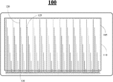
도 1은 휴대용 전자 디바이스 내에 통합되는 근접 센서 장치의 일 실시예를 도시한다.
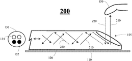
도 2는 근접 센서 장치 컴포넌트의 일 실시예를 도시한다.
도 3은 휴대용 전자 디바이스(PED) 내에 통합되는 근접 센서 장치의 다른 실시예를 도시한다.
도 4는 근접 센서 장치 컴포넌트의 다른 실시예를 도시한다.
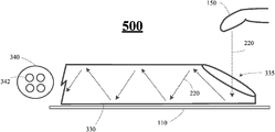
도 5는 근접 센서 장치 컴포넌트의 다른 실시예를 도시한다.
도 6은 휴대용 전자 디바이스(PED) 내에 통합되는 근접 센서 장치의 다른 실시예를 도시한다.
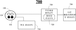
도 7은 근접 센서 장치 프로세싱 컴포넌트의 일 실시예를 도시한다.
도 8은 근접 센서 장치 프로세싱 컴포넌트의 다른 실시예를 도시한다.
도 9는 근접 센서 장치 프로세싱 컴포넌트의 다른 실시예를 도시한다.
도 10은 논리 흐름의 일 실시예를 도시한다.
도 11은 컴퓨팅 아키텍처의 일 실시예를 도시한다.Figure 1 illustrates one embodiment of a proximity sensor device incorporated within a portable electronic device.
Figure 2 shows an embodiment of a proximity sensor device component.
Figure 3 illustrates another embodiment of a proximity sensor device incorporated within a portable electronic device (PED).
Figure 4 shows another embodiment of a proximity sensor device component.
Figure 5 shows another embodiment of a proximity sensor device component.
Figure 6 shows another embodiment of a proximity sensor device incorporated within a portable electronic device (PED).
Figure 7 illustrates one embodiment of a proximity sensor device processing component.
Figure 8 shows another embodiment of the proximity sensor device processing component.
9 shows another embodiment of the proximity sensor device processing component.
10 illustrates one embodiment of a logic flow.
Figure 11 illustrates one embodiment of a computing architecture.
다양한 실시예에서, 근접 센서 장치는 현재의 터치스크린 장치들과 관련된 공통적인 결함에 대해 다룬다.In various embodiments, the proximity sensor device addresses a common defect associated with current touch screen devices.
근접 센서 장치는, 일부 실시예에서, 복수의 광섬유들을 이용한다. 광섬유들은 일단이 개방되고 빛을 전도하도록 동작할 수 있으며, 복수의 광섬유들에 대한 개방단(open end)들이 그리드(grid)를 형성하도록 구성될 수 있다. 복수의 엘이디(LED)들은 대응하는 광섬유와 통신가능하게 결합(communicatively coupled)될 수 있다. 복수의 엘이디들은 대응하는 광섬유를 통해서 개방단 외부로 적외선(IR)을 방출하도록 동작할 수 있다. 복수의 광전 센서(photoelectronic sensor)들은 광섬유와 통신가능하게 결합될 수 있다. 복수의 광전 센서들은 객체로부터 반사되어 복수의 광섬유들의 개방단 내로 되돌아오는 방출 광(emitted light)을 검출하도록 동작할 수 있다. The proximity sensor device, in some embodiments, uses a plurality of optical fibers. The optical fibers can operate to open one end and conduct light, and the open ends for a plurality of optical fibers can be configured to form a grid. A plurality of LEDs may be communicatively coupled to a corresponding optical fiber. The plurality of LEDs may be operable to emit infrared (IR) radiation outside the open end through a corresponding optical fiber. A plurality of photoelectronic sensors may be communicatively coupled to the optical fiber. A plurality of photoelectric sensors may be operable to detect emitted light reflected from the object and back into the open end of the plurality of optical fibers.
프로세싱 컴포넌트는 복수의 광전 센서들과 통신가능하게 결합될 수 있다. 프로세싱 컴포넌트는 복수의 광전 센서들로부터 신호를 수신하도록 동작할 수 있다. 신호는 객체로부터 반사되어 복수의 광섬유들의 개방단 내로 되돌아오는 반사되고 감지된 방출 광을 나타낼 수 있다. 프로세싱 컴포넌트는 신호를 처리하여 복수의 광섬유들의 개방단들로부터 방출 광이 반사되는 객체까지의 거리를 결정할 수도 있다. The processing component may be communicatively coupled with a plurality of photoelectric sensors. The processing component may be operable to receive signals from the plurality of photoelectric sensors. The signal may be reflected from the object and reflected and reflected back into the open end of the plurality of optical fibers. The processing component may process the signal to determine the distance from the open ends of the plurality of optical fibers to the object from which the emitted light is reflected.
잘못된 광 검출(false light detection)을 막기 위해, 변조 컴포넌트가 엘이디들에 결합될 수 있고 방출 광을 특정 패턴으로 변조하도록 동작할 수 있다. 프로세싱 컴포넌트는 검출된 방출 광을 나타내는 신호를 필터링하여 변조된 특정 패턴에 부합하지 않는 광을 무시하도록 동작할 수 있다.To prevent false light detection, a modulation component can be coupled to the LEDs and operate to modulate the emitted light in a particular pattern. The processing component may operate to filter the signal representing the detected emitted light and ignore the light that does not conform to the particular pattern being modulated.
프로세싱 컴포넌트는 반사된 방출 광을 검출한 복수의 광섬유들의 개방단들에 대한 그리드 위치에 기초하여, 직교 좌표 시스템(Cartesian coordinate system)에 따른 객체의 직교 좌표 (X, Y)와 같은 객체의 평면 위치를 결정하도록 동작할 수 있다. 이 정보를 이용하여, 프로세싱 컴포넌트는 직교 좌표 (X, Y) 및 복수의 광섬유들의 개방단들로부터 방출 광이 반사되는 객체까지의 거리에 기초하는 액션을 개시하도록 동작할 수 있다.The processing component is configured to determine, based on the grid position for the open ends of the plurality of optical fibers that have detected the reflected emitted light, to determine a plane position of the object, such as Cartesian coordinates (X, Y) of the object according to a Cartesian coordinate system Lt; / RTI > With this information, the processing component can operate to initiate an action based on the Cartesian coordinates (X, Y) and the distance from the open ends of the plurality of optical fibers to the object from which the emitted light is reflected.
일부 실시예에서, 엘이디 광을 방출하기 위해 사용되는 복수의 광섬유들은 반사 광을 검출하기 위해 사용되는 광섬유들과 동일한 것일 수 있다. 또는, 별개의 광섬유들의 집합이 반사 광을 검출하기 위해 사용될 수도 있다. 또한, 방출 광은 별도로 동작하는 하나 이상의 엘이디들로부터 방출될 수 있다.In some embodiments, the plurality of optical fibers used to emit the LED light may be the same as the optical fibers used to detect the reflected light. Alternatively, a separate set of optical fibers may be used to detect reflected light. Also, the emitted light may be emitted from one or more LEDs that operate separately.
이제 도면이 참조되고, 동일한 참조 부호는 동일한 구성요소를 나타내기 위해 사용된다. 이하의 기재 내용에서는 설명을 위하여 여러 구체적인 세부 사항들이 그들의 완전한 이해를 제공하기 위해 제시된다. 그러나, 이들 구체적인 세부 사항들 없이도 신규한 실시예들이 실시될 수 있음은 명백한 것이다. 다른 예시들에서, 주지의 구조 및 디바이스는 그들에 관한 설명을 용이하게 하기 위해 블록 다이어그램 형태로 도시된다. 그 의도는 청구된 대상의 사상 및 범주에 속하는 모든 변형물, 균등물, 및 대안을 포함하도록 하는 것이다. The drawings are now referenced, and the same reference numerals are used to denote the same elements. In the following description, for purposes of explanation, numerous specific details are set forth in order to provide a thorough understanding of the invention. It will, however, be evident that new embodiments may be practiced without these specific details. In other instances, well-known structures and devices are shown in block diagram form in order to facilitate describing them. The intent is to include all variations, equivalents, and alternatives falling within the spirit and scope of the claimed subject matter.
도 1은 휴대용 전자 디바이스(PED)(100) 내에 통합되는 근접 센서 장치(105)의 일 실시예를 도시한다. PED(100)는 스마트폰, 핸드헬드 태블릿 컴퓨터 등과 같은 것일 수 있다. PED(100)는 물리적인 사용자 입력을 수신하고 처리하도록 동작하는 터치스크린 컴포넌트(110)를 포함할 수도 있다. 근접 센서 장치는 복수의 광섬유들(120)을 포함할 수 있다. 복수의 광섬유들(120) 각각은 개방단(125)에서 종결된다. "개방단"이라는 용어는 광섬유를 가로질러 주변 환경으로 빛을 직접적으로 방출하거나, 개방부를 통해 반사 광을 수신하고 그것을 광섬유의 길이를 따라 다시 전도할 수 있거나, 이들 양자 모두일 수도 있는 광섬유의 일단을 일컫는다. 복수의 광섬유들(120)의 개방단들(125)은 터치스크린(110)의 표면을 덮는(overlay) 그리드를 형성하도록 구성될 수 있다. 복수의 광섬유들 각각은 센서 장치(130)가 존재할 수 있는 다른 일단에서 종결될 수도 있다.1 illustrates one embodiment of a
일 실시예에서, 복수의 광섬유들(120)은 사용자에게 보이지 않도록 또는 복수의 광섬유들(120)의 배열 아래에 위치되는 디스플레이 유닛 상의 그래픽을 방해하지 않기 위해서 투명할 수 있다. 실시예들이 이런 맥락에 한정되는 것은 아니다. In one embodiment, the plurality of
도 2는 근접 센서 장치 컴포넌트의 일 실시예(200)를 도시한다. 센서 장치(130)는 광섬유(120)의 일단에 위치될 수 있다. 이 실시예에서, 센서 장치(130)는 하나 이상의 광원(132) 및 하나 이상의 광전 센서(134)를 포함한다. 광원(들)(132)은, 예를 들어, 적외선(IR)을 방출하도록 동작하는 엘이디(LED)일 수 있다. 동작 중에, 광원(들)(132)은 광섬유(120)를 통해 일단(125) 밖으로 적외선(210)을 방출할 수 있다. 방출된 적외선(210)은 화살표로 도시된 것처럼 주변 환경으로 지나갈 수 있다. 만약, 예를 들어, 손가락과 같은 객체(150)가 존재하면, 객체(150)는 방출된 적외선(210)을 반사할 수 있다. 반사 광(220)은 광섬유(120)의 개방단(125) 내로 귀환 경로(return path)를 따라서 센서 장치(130)에 도달(strike)할 때까지 광섬유(120)를 가로지를 수 있다. 센서 장치(130) 상의 광전 센서(134)는 그 후 반사 광(220)을 검출할 수 있다. 실시예들이 이런 맥락에 한정되는 것은 아니다. 2 illustrates one
도 3은 휴대용 전자 디바이스(PED)(300) 내에 통합되는 근접 센서 장치(305)의 다른 실시예를 도시한다. PED(300)는 스마트폰, 핸드헬드 태블릿 컴퓨터 등과 같은 것일 수 있다. PED(300)는 물리적인 사용자 입력을 수신하고 처리하도록 동작하는 터치스크린 컴포넌트(110)를 포함할 수도 있다. 이 실시예에서는, 복수의 광섬유들의 두 가지 집합이 있을 수 있다. 복수의 광섬유들의 제1 집합(310)은 빛을 방출하도록 동작할 수 있는 반면, 복수의 광섬유들의 제2 집합(330)은 빛을 검출하도록 동작할 수 있다. 복수의 광섬유들의 두 집합(310, 330) 모두는 개방단(315, 335)을 각각 포함할 수 있고, 터치스크린(110)의 표면을 덮는 그리드를 형성하도록 구성될 수 있다. 제1 집합의 광섬유(310)는 각각 광원(320)이 존재할 수 있는 다른 일단에서 종결될 수 있다. 제2 집합의 광섬유(330)는 각각 센서 장치(340)가 존재할 수 있는 다른 일단에서 종결될 수 있다. 3 illustrates another embodiment of a
일 실시예에서, 복수의 광섬유들(310, 330)은 사용자에게 보이지 않도록 또는 복수의 광섬유들(310, 330)의 배열 아래에 위치되는 디스플레이 유닛 상의 그래픽을 방해하지 않기 위해서 투명할 수 있다. 실시예들이 이런 맥락에 한정되는 것은 아니다. In one embodiment, the plurality of
도 4는 근접 센서 장치 컴포넌트의 다른 실시예(400)를 도시한다. 이 실시예에서는, 제1 집합으로부터의 광섬유(310)가 도시된다. 광원(320)은 광섬유(310)의 일단에 위치될 수 있다. 이 실시예에서, 광원(320)은 하나 이상의 소자(element)(322)를 포함할 수 있다. 소자(322)는, 예를 들어, 적외선(IR)을 방출하도록 동작하는 엘이디(LED)일 수 있다. 동작 중에, 소자(들)(322)는 광섬유(310)를 통해 일단(315) 밖으로 적외선(210)을 방출할 수 있다. 방출된 적외선(210)은 화살표로 도시된 것처럼 주변 환경으로 지나갈 수 있다. 만약, 예를 들어, 손가락과 같은 객체(150)가 존재하면, 객체(150)는 방출된 적외선(210)을 반사할 수 있다. 실시예들이 이런 맥락에 한정되는 것은 아니다. 4 shows another
도 5는 근접 센서 장치 컴포넌트의 다른 실시예를 도시한다. 이 실시예에서는, 제2 집합으로부터의 광섬유(330)가 도시된다. 센서 장치(340)는 광섬유(330)의 일단에 위치될 수 있다. 이 실시예에서, 센서 장치(340)는 하나 이상의 광전 센서(342)를 포함할 수 있다. 반사 광(220)은 광섬유(330)의 개방단(335) 내로 귀환 경로를 따를 수 있다. 반사 광(220)은 그 후 센서 장치(340)의 광전 센서(342)에 도달할 때까지 광섬유(330)를 가로지를 수 있다. 센서 장치(340)의 광전 센서(342)는 그 후 반사 광(220)을 검출할 수 있다. 실시예들이 이런 맥락에 한정되는 것은 아니다. Figure 5 shows another embodiment of a proximity sensor device component. In this embodiment, an
도 6은 휴대용 전자 디바이스(PED)(600) 내에 통합되는 근접 센서 장치(605)의 다른 실시예를 도시한다. PED(600)는 스마트폰, 핸드헬드 태블릿 컴퓨터 등과 같은 것일 수 있다. PED(600)는 물리적인 사용자 입력을 수신하고 처리하도록 동작하는 터치스크린 컴포넌트(110)를 포함할 수도 있다. 이 실시예에서는, 하나 이상의 광원이 PED(600)의 터치스크린 컴포넌트(110)의 픽셀(610)과 통합될 수 있다. 이 실시예에서, 광원(들)은 하나 이상의 소자(612)를 포함할 수 있다. 소자(612)는, 예를 들어, 적외선(IR)을 방출하도록 동작하는 엘이디(LED)일 수 있다. 동작 중에, 엘이디 소자(612)는 터치스크린 내에 배치될 수 있고, 터치스크린(110) 내의 각 픽셀(610)로부터 적외선을 방출할 수 있다. 각각의 픽셀(610) 내의 다른 엘이디 소자는 적색, 녹색 및 청색 광을 방출할 수 있다. 만약, 예를 들어, 손가락과 같은 객체가 존재하면, 객체는 방출된 적외선을 반사할 수 있다. 도 6에 도시된 픽셀(610)은 반드시 그 비율에 따라야 하는 것은 아니며, 그 구조를 잘 설명하기 위한 것일 뿐이다. 실시예들은 이런 맥락에 한정되지 않는다.6 shows another embodiment of a proximity sensor device 605 incorporated within a portable electronic device (PED) The PED 600 may be a smart phone, a handheld tablet computer, or the like. The PED 600 may include a
복수의 광섬유들(620)의 집합은 빛을 검출하도록 동작할 수 있다. 복수의 광섬유들(620) 각각은 개방단(625)에서 종결된다. 복수의 광섬유들(620)의 개방단들(625)은 터치스크린(110)의 표면을 덮는 그리드를 형성하도록 구성될 수 있다. 복수의 광섬유들 각각은 센서 장치(630)가 존재할 수 있는 다른 일단에서 종결될 수도 있다. 이 실시예에서, 센서 장치(630)는 도 5에 도시된 것과 유사한 하나 이상의 광전 센서를 포함할 수 있다. 반사 광은 광섬유(620)의 개방단(625) 내로 귀환 경로를 따를 수 있다. 반사 광은 그 후 센서 장치(630)의 광전 센서에 도달할 때까지 광섬유(620)를 가로지를 수 있다. 센서 장치(630)의 광전 센서는 그 후 도 5를 참조하여 설명된 바와 유사하게 반사 광을 검출할 수 있다. A collection of a plurality of optical fibers 620 may be operable to detect light. Each of the plurality of optical fibers 620 is terminated at an open end 625. The open ends 625 of the plurality of optical fibers 620 may be configured to form a grid that covers the surface of the
일 실시예에서, 복수의 광섬유들(620)은 사용자에게 보이지 않도록 또는 복수의 광섬유들(620)의 배열 아래에 위치되는 디스플레이 유닛 상의 그래픽을 방해하지 않기 위해서 투명할 수 있다. 실시예들이 이런 맥락에 한정되는 것은 아니다.In one embodiment, the plurality of optical fibers 620 may be transparent so as not to be visible to the user or to not interfere with the graphics on the display unit located below the array of the plurality of optical fibers 620. [ The embodiments are not limited in this context.
도 7은 근접 센서 장치 프로세싱 컴포넌트의 일 실시예(700)를 도시한다. 도 1로부터의 센서 장치(130)가 도시되고, 변조 컴포넌트(710) 및 프로세싱 컴포넌트(720)와 통신가능하게 결합될 수 있다. 이 실시예에서, 센서 장치(130)는 도 1 및 2에 도시되고 이에 관하여 설명된 바와 같은 광원(132) 및 광전 센서(134)를 모두 포함한다. 변조 컴포넌트(710)는 광원(132)으로부터 방출된 빛을 특정 패턴으로 변조하도록 동작할 수 있다. 변조는 패턴을 형성하는 소정의 시퀀스에 따라 광원(132)을 초당 수천회 켜고 꺼서 달성될 수 있다. 실시예들이 이런 맥락에 한정되는 것은 아니다.FIG. 7 illustrates one
프로세싱 컴포넌트(720)는 검출된 반사 광을 나타내는 신호를 필터링하도록 동작할 수 있는 필터링 컴포넌트(725)를 포함할 수 있다. 검출된 반사 광을 나타내는 신호는 도 1에서 볼 수 있는 바와 같은 터치스크린의 표면 위의 객체를 나타낼 수 있고 센서 장치(130)의 광전 센서(134)로부터 수신될 수 있다. 이 신호는 빛이 광원(132)에 의해 방출되었을 경우 변조 컴포넌트(710)에 의해 구현되었을 수 있는 변조 패턴에 따라 필터링될 수 있다. 알려진 패턴으로 빛을 방출함으로써, 검출되는 반사 광은 반사 광 내에서 노이즈를 만들 수 있는 환경적 간섭(environmental interference)을 제거하기 위해 필터링될 수 있다. 따라서, 오직 광원(132)에 의해 방출된 빛만 검출될 수 있고 프로세싱 컴포넌트(720)에 의해 액팅될 수 있다. 실시예들이 이런 맥락에 한정되는 것은 아니다.The
프로세싱 컴포넌트(720)는 검출된 반사된 방출 광(detected reflected emitted light)을 전도하는 복수의 광섬유들의 개방단들의 그리드 위치에 기초하여 터치 스크린에 대한 객체의 (X, Y) 좌표를 결정하도록 동작할 수 있다. 프로세싱 컴포넌트(720)는 복수의 광섬유들의 개방단들로부터 객체까지일 수 있는 거리를 결정하도록 더 동작할 수 있다. 거리는 검출된 반사 광에 내재하는 요소들에 기초하여 계산될 수 있다. 이러한 요소는 반사 광의 세기(intensity)일 수 있다. 더 큰 세기의 반사 광은 더 작은 세기의 빛을 반사하는 객체에 비해 객체가 터치스크린에 더 가까이 있음을 나타낸다. The
다른 요소는 검출된 반사 광의 분산(dispersion)이 될 수 있다. 빛의 분산은 객체로부터 반사되는 빛을 더 많은 광전 센서가 검출할수록 커질 것이다. 빛의 분산은 객체로부터 반사되는 빛을 검출하는 광전 센서가 더 적을수록 작아질 것이다. 빛의 분산은 객체가 터치스크린으로부터 있을 수 있는 거리와 관련된다. 객체가 터치스크린에 더 가까울수록 분산은 작아지는데, 이는 터치스크린 상의 더욱 제한된 표면에 빛이 반사될 것이기 때문이다. 역으로, 객체가 터치스크린으로부터 더 멀어질수록 분산은 커지는데, 이는 터치스크린 상의 더욱 넓은 표면에 빛이 반사될 것이기 때문이다. 실시예들이 이런 맥락에 한정되는 것은 아니다. The other element may be a dispersion of the detected reflected light. The dispersion of light will increase as more photoelectric sensors detect the light reflected from the object. The smaller the photoelectric sensor that detects the light reflected from the object, the smaller the scattering of light. The dispersion of light is related to the distance an object can be from the touch screen. The closer the object is to the touch screen, the smaller the dispersion, because the light will be reflected on a more limited surface on the touch screen. Conversely, the farther away an object is from the touch screen, the greater the dispersion, because the light will be reflected on a wider surface on the touch screen. The embodiments are not limited in this context.
프로세싱 컴포넌트(720)는 객체의 (X, Y) 좌표 및 방출 광을 반사하는 객체에 대한 터치스크린으로부터의 거리에 기초하여 액션 또는 태스크가 개시되도록 할 수 있는 휴대용 전자 디바이스 내의 애플리케이션 및 컴포넌트(730)와 통신가능하게 결합될 수 있다. 실시예들이 이런 맥락에 한정되는 것은 아니다.The
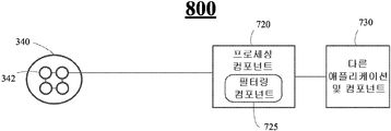
도 8은 근접 센서 장치 프로세싱 컴포넌트의 다른 실시예(800)를 도시한다. 도 3으로부터의 센서 장치(340)가 도시되고, 프로세싱 컴포넌트(720)와 통신가능하게 결합될 수 있다. 이 실시예에서, 센서 장치(340)는 도 3 및 5에 도시되고 이에 관하여 설명된 바와 같은 광전 센서(342)를 포함한다. 프로세싱 컴포넌트(720)는 필터링 컴포넌트(725)를 포함할 수 있고 휴대용 전자 디바이스 내의 다른 애플리케이션 및 컴포넌트(730)와 통신가능하게 결합될 수 있다. 프로세싱 컴포넌트(720)와, 필터링 컴포넌트(725)와, 다른 애플리케이션 및 컴포넌트(730)의 기능은 도 7과 관련하여 전술되어 있다. 실시예들이 이런 맥락에 한정되는 것은 아니다.Figure 8 illustrates another
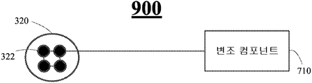
도 9는 근접 센서 장치 프로세싱 컴포넌트의 다른 실시예(900)를 도시한다. 도 3으로부터의 광원(320)이 도시되고, 변조 컴포넌트(710)와 통신가능하게 결합될 수 있다. 이 실시예에서, 광원(320)은 도 3 및 4에 도시되고 이에 관하여 설명된 바와 같은 소자(322)를 포함한다. 변조 컴포넌트(710)는 소자(322)로부터 방출되는 빛을 확산 스펙트럼 기법(spread spectrum techniques)에 의해 수행되는 것과 유사한 특정 패턴으로 변조하도록 동작할 수 있다. 실시예들이 이런 맥락에 한정되는 것은 아니다.9 illustrates another
개시되는 아키텍처의 신규한 측면을 수행하기 위한 예시적인 방법을 나타내는 하나 이상의 플로우 차트가 본 명세서에 포함된다. 설명의 간소화 목적으로, 본 명세서에 도시되는 하나 이상의 방법은, 예를 들어, 플로우 차트 또는 플로우 다이어그램의 형태로 도시되고 일련의 동작으로 설명되지만, 방법이 그 동작 순서에 한정되는 것은 아니며, 그 중의 일부 동작들은 본 명세서에 도시되고 설명된 것과 상이한 순서 및/또는 다른 동작과 동시적으로 발생할 수 있음이 이해되어야 할 것이다. 예를 들어, 본 기술분야의 통상의 기술자는 방법이 상태 다이어그램과 같은 일련의 관련 상태 또는 이벤트로서 대안적으로 표현될 수 있음을 이해할 수 있을 것이다. 또한, 방법에 관해 설명된 동작이 신규한 구현을 위하여 모두 요구되어야 하는 것은 아닐 수 있다. One or more flowcharts are included herein that illustrate exemplary methods for performing the novel aspects of the disclosed architecture. For purposes of streamlining the description, one or more of the methods illustrated herein are illustrated in the form of a flowchart or flow diagram, for example, and described in terms of a series of operations, but the method is not limited to the order of operations, It is to be understood that some operations may occur concurrently with other sequences and / or other operations than those illustrated and described herein. For example, one of ordinary skill in the art will understand that a method may alternatively be represented as a series of related states or events, such as state diagrams. Also, the operations described with respect to the method may not all be required for a new implementation.
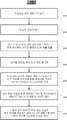
도 10은 휴대용 전자 디바이스의 터치스크린으로부터 객체의 거리가 계산될 수 있는 논리 흐름(1000)의 일 실시예를 도시한다. 논리 흐름(1000)은 본 명세서에서 설명되는 하나 이상의 실시예에 의해 실행되는 동작의 일부 또는 전부를 나타낼 수 있다. 10 illustrates one embodiment of
근접 센서 장치는 빛이 광원으로부터 복수의 광섬유들을 통해 각 광섬유의 개방단 외부로 전도될 수 있는 방법을 구현할 수 있다. 복수의 광섬유들은 다른 일단 상에서 대응하는 광원과 통신가능하게 결합될 수 있다. 복수의 광섬유들은 개방단들이 휴대용 전자 디바이스의 터치스크린 표면을 덮는 그리드를 형성하도록 구성될 수 있다. 근접 센서 장치는 광섬유 개방단의 그리드 상부의 근거리에 있을 수 있는 객체로부터 반사되어 되돌아오는 방출 광을 검출하기 위해 복수의 광전 센서들을 구현할 수 있다. 일 실시예에서, 광전 센서들은 광섬유 각각 내의 광원과 실질적으로 함께 위치될 수 있다. 다른 실시예에서, 광전 센서들은 빛을 방출하는 광섬유들의 집합과 유사한 그리드 형태로 배치될 수 있는 광섬유들의 제2 집합 내에 위치될 수 있다. The proximity sensor device can implement a method by which light can be conducted from the light source through the plurality of optical fibers to the open end of each optical fiber. The plurality of optical fibers can be communicably coupled with corresponding light sources at the other end. The plurality of optical fibers may be configured such that the open ends form a grid covering the touch screen surface of the portable electronic device. The proximity sensor device may implement a plurality of photoelectric sensors to detect emitted light that is reflected back from an object that may be close at the top of the grid of fiber optic open ends. In one embodiment, the photoelectric sensors can be located substantially co-locating with a light source within each of the optical fibers. In another embodiment, the photoelectric sensors can be located in a second set of optical fibers that can be arranged in a grid shape similar to a set of optical fibers emitting light.
근접 센서 장치는 복수의 광전 센서들로부터 신호를 수신할 수 있는 프로세싱 컴포넌트를 구현할 수 있고, 그 신호는 반사되어 돌아온 검출된 방출 광을 나타낼 수 있다. 프로세싱 컴포넌트는 신호에 기초하여 그리드 상부에 있을 수 있는 객체의 거리를 결정할 수 있다. 근접 센서 장치는 비가시(invisible) 주파수 영역, 특히 적외선 영역의 빛을 방출할 수 있다. 근접 센서 장치는 광원으로부터 방출되는 빛을 특정 패턴으로 변조할 수 있다. 변조는 광원으로부터의 반사 광이 장치에 의해 필터링되어 주변적 또는 환경적 빛으로부터 구별될 수 있도록 유일한 광 시그니처(unique light signature)를 생성하기 위해 일어날 수 있다. The proximity sensor device may implement a processing component capable of receiving a signal from a plurality of photoelectric sensors, the signal being capable of indicating the detected emitted light that is reflected back. The processing component may determine the distance of an object that may be on top of the grid based on the signal. The proximity sensor device may emit light in an invisible frequency region, particularly in the infrared region. The proximity sensor device can modulate the light emitted from the light source in a specific pattern. Modulation may occur to produce a unique light signature such that the reflected light from the light source is filtered by the device to distinguish it from ambient or environmental light.
도 10에 도시된 실시예에서, 블록(1010)에서는 근접 센서 장치가 광원으로부터의 적외선을 특정 패턴으로 변조할 수 있다. 예를 들어, 광원과 결합된 변조 컴포넌트는 방출 광에 유일한 식별 특성을 제공하기 위해 빛을 특정 패턴으로 생성하고 변조할 수 있다. 변조는, 예를 들어, 확산 스펙트럼 기법과 유사할 수 있다. 실시예들이 이 예시에 한정되는 것은 아니다.In the embodiment shown in FIG. 10, at
논리 흐름(1000)은 블록(1020)에서 복수의 광섬유들의 그리드 내의 각 광섬유로부터 빛을 방출할 수 있다. 예를 들어, 광원은 복수의 광섬유들을 통해 광섬유들 각각에 대한 개방단을 나와 인근 환경으로 전도되는 변조된 적외선을 생성할 수 있다. 광섬유들의 개방단들은 예를 들어, 터치스크린 장치를 덮는 (X, Y) 그리드로 배치될 수 있다. 실시예들이 이 예시에 한정되는 것은 아니다.
논리 흐름(1000)은 블록(1030)에서 알려진 위치 내의 광섬유에 대응하는 광전 센서에서 변조된 패턴의 반사 광을 검출할 수 있다. 예를 들어, 일 실시예에서, 광섬유들의 대응 그리드는 각각 광전 센서를 포함할 수 있다. 다른 실시예에서, 광전 센서는 통합된 센서 장치 상의 광원과 실질적으로 함께 위치될 수 있고, 변조된 적외선을 방출하기 위해 사용되는 것과 동일한 광섬유를 이용할 수 있다. 광전 센서는 하나 이상의 광섬유 단부 상부에 위치되는 객체로부터 반사되는 빛을 검출할 수 있다.
광원 및 광전 센서가 동일한 광섬유에 함께 위치되는 실시예에서, 반사 광은 개방단으로 다시 진입할 수 있고 광전 센서에 도달할 때까지 광섬유의 길이를 가로지룰 수 있다. 광원 및 광전 센서가 별개의 광섬유에 있는 실시예에서, 반사 광은 빛을 방출하지 않는 광섬유(들)의 개방단(들)에 진입할 수 있고 광전 센서에 도달할 때까지 광섬유(들)의 길이를 가로지를 수 있다. 광전 센서는 검출 광(detected light)을 나타내는 신호를 프로세싱 컴포넌트로 전달할 수 있다. 실시예들이 이 예시에 한정되는 것은 아니다.In embodiments where the light source and the photoelectric sensor are co-located in the same optical fiber, the reflected light can enter the open end again and traverse the length of the optical fiber until it reaches the photoelectric sensor. In embodiments where the light source and the photoelectric sensor are in separate optical fibers, the reflected light can enter the open end (s) of the optical fiber (s) that do not emit light and the length of the optical fiber (s) . ≪ / RTI > The photoelectric sensor can deliver a signal indicative of the detected light to the processing component. The embodiments are not limited to these examples.
논리 흐름(1000)은 블록(1040)에서 변조된 패턴에 따라 검출된 반사 광을 필터링할 수 있다. 예를 들어, 프로세싱 컴포넌트의 제어를 받는 필터링 컴포넌트는 변조 컴포넌트에 의해 적용된 변조 패턴에 따라 검출 광을 나타내는 신호를 필터링할 수 있다. 변조 스킴(scheme)은 방출 광에 유일한 식별 특성을 부여한다. 근접 센서 장치는 광섬유에 의해 원래 방출되었다가 광전 센서에 의해 검출된 빛에만 관심을 가질 수 있다. 주변 광 또는 태양광과 같은 기타 검출 광은 이러한 기타 광의 근원을 알 수 없기 때문에 객체 거리 계산과 무관할 수 있고, 어떠한 거리 계산에도 고려되지 않는다. 실시예들이 이 예시에 한정되는 것은 아니다.
논리 흐름(1000)은 블록(1050)에서 반사 광을 검출한 광섬유 개방단(들)의 알려진 위치에 기초하여 빛을 반사하는 객체, 예컨대, 손가락 또는 스타일러스의 근사 평면 위치(approximation planar location)(예컨대, (X, Y) 좌표)를 결정할 수 있다. 예를 들어, 검출 광을 나타내는 신호는 광섬유들의 개방단들에 의해 형성되는 그리드 내의 광전 센서들의 작은 부분집합에서 비롯될 수 있다. 그리드는 광전 센서와 관련된 광섬유의 각 개방단에 대한 평면 위치(예컨대, (X, Y) 좌표)가 알려지도록 펼쳐질 수 있다. 변조된 방출 광을 반사하는 객체의 근접 평면 위치를 결정하는 것은 어떤 광전 센서가 검출 광을 나타내는 신호를 제공했는지 결정하는 것을 수반할 수 있다. 실시예들이 이 예시에 한정되는 것은 아니다.
논리 흐름(1000)은 블록(1060)에서 반사 광을 검출하는 광전 센서에 대응하는 광섬유(들)의 개방단(들)로부터의 객체의 거리를 계산할 수 있다. 거리는 검출된 반사 광에 내재하는 요소에 기초하여 계산될 수 있다. 이러한 요소는 반사 광의 세기일 수 있다. 더 큰 세기의 반사 광은 더 작은 세기의 빛을 반사하는 객체에 비해 객체가 터치스크린에 더 가까이 있음을 나타낸다.
다른 요소는 검출된 반사 광의 분산이 될 수 있다. 빛의 분산은 객체로부터 반사되는 빛을 더 많은 광전 센서가 검출할수록 커질 것이다. 빛의 분산은 객체로부터 반사되는 빛을 검출하는 광전 센서가 더 적을수록 작아질 것이다. 빛의 분산은 객체가 터치스크린으로부터 있을 수 있는 거리와 관련된다. 객체가 터치스크린에 더 가까울수록 분산은 작아지는데, 이는 터치스크린 상의 더욱 제한된 표면에 빛이 반사될 것이기 때문이다. 역으로, 객체가 터치스크린으로부터 더 멀어질수록 분산은 커지는데, 이는 터치스크린 상의 더욱 넓은 표면에 빛이 반사될 것이기 때문이다. 실시예들이 이런 맥락에 한정되는 것은 아니다. The other element may be the dispersion of the detected reflected light. The dispersion of light will increase as more photoelectric sensors detect the light reflected from the object. The smaller the photoelectric sensor that detects the light reflected from the object, the smaller the scattering of light. The dispersion of light is related to the distance an object can be from the touch screen. The closer the object is to the touch screen, the smaller the dispersion, because the light will be reflected on a more limited surface on the touch screen. Conversely, the farther away an object is from the touch screen, the greater the dispersion, because the light will be reflected on a wider surface on the touch screen. The embodiments are not limited in this context.
논리 흐름(1000)은 블록(1070)에서 객체의 근접 평면 위치(예컨대, X, Y 좌표) 및 광섬유 개방단들의 그리드에 대한 객체의 거리에 기초하여 응답을 개시할 수 있다. 예를 들어, 근접 센서 장치는 스마트폰과 같은 휴대용 전자 디바이스(PED) 내에 구현될 수 있다. 스마트폰은 사용자 액션을 검출하고 해석하도록 동작하는 터치스크린을 구비할 수 있다. 근접 센서 장치는 스마트폰 디스플레이 상에 디스플레이된 아이콘에 부합하는 근접 (X, Y) 위치에서 터치스크린 상방 약 3 센티미터에 객체가 있다는 것을 결정할 수 있다. 이 거리는 (특히, 만약 시간이 지나면서 감소할 경우) 이 아이콘과 상호 작용하려는 사용자의 의도로서 프로세싱 컴포넌트에 의해 해석될 수 있다. 따라서, 프로세싱 컴포넌트는 (X, Y) 위치 및 터치스크린(110)에 대한 객체의 감소하는 거리에 기초하여 하나 이상의 액션을 개시할 수 있다.
예를 들어, 한 액션은 아이콘에 대한 하나 이상의 옵션 예컨대, 열기, 삭제, 폴더로 이동, 또는 숨기기와 같은 것을 포함하는 숨겨진 메뉴를 팝업하는 것일 수 있다. 사용자는 이제 터치스크린에 접촉할 객체를 전술된 숨겨진 메뉴 옵션들 중 하나에 대응하는 지점으로 다시 향하도록(re-direct) 할 수 있다. 실시예들이 이 예시에 한정되는 것은 아니다.For example, an action may be popping up a hidden menu that includes one or more options for the icon, such as opening, deleting, moving to a folder, or hiding. The user can now re-direct the object to contact the touch screen back to the point corresponding to one of the hidden menu options described above. The embodiments are not limited to these examples.
다른 액션은 시간이 흐르면서 터치스크린의 표면에 대한 객체의 거리 변화를 측정할 수 있으므로 거리의 3차원을 포함하도록 하는 사용자 인터페이스 액션 또는 내비게이션을 확장하는 것일 수 있다. Other actions may be to extend the user interface action or navigation to include three dimensions of distance, as time can vary the distance of the object relative to the surface of the touch screen.
일 예시에서, 객체의 평면 좌표는 객체가 휴대용 전자 디바이스에 의해 디스플레이 중인 그래픽 사용자 인터페이스(GUI)에 대한 그래픽 또는 볼륨 제어 아이콘 상부에 호버링(hovering) 중이라는 것을 암시할 수 있다. 볼륨은 터치스크린에 대한 객체의 거리에 기초하여 제어될 수 있다. 예를 들어, 객체를 터치스크린에 가까이 이동시키는 것은 프로세싱 컴포넌트로 하여금 휴대용 전자 디바이스의 볼륨을 낮추도록 할 수 있는 반면, 객체를 터치스크린으로부터 더 떨어트리는 것은 프로세싱 컴포넌트로 하여금 휴대용 전자 디바이스의 볼륨을 높이도록 할 수 있다. 프로세싱 컴포넌트는 슬라이딩 스케일을 이용하는 다른 GUI 아이콘에 관한 유사 기능을 수행하도록 동작되어 휴대용 전자 디바이스의 양상을 제어할 수도 있다. 다른 예시는 휴대용 전자 디바이스의 디스플레이 컴포넌트의 백라이팅을 디밍(dimming)하거나 밝게 할 수도 있다. 실시예들이 이 예시들에 한정되는 것은 아니다.In one example, the plane coordinates of the object may imply that the object is hovering above a graphical or volume control icon for the graphical user interface (GUI) being displayed by the portable electronic device. The volume can be controlled based on the distance of the object to the touch screen. For example, moving an object closer to the touch screen may cause the processing component to lower the volume of the portable electronic device, while further dropping the object from the touch screen may cause the processing component to increase the volume of the portable electronic device . The processing component may be operable to perform similar functions with respect to other GUI icons utilizing the sliding scale to control aspects of the portable electronic device. Other examples may dim or brighten the backlighting of the display component of the portable electronic device. The embodiments are not limited to these examples.
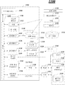
도 11은 전술된 다양한 실시예들을 구현하는 데 적합한 예시적인 컴퓨팅 아키텍처(1100)의 실시예를 도시한다. 이 응용에서 사용되는 것처럼, "시스템", "디바이스" 및 "컴포넌트"라는 용어는 컴퓨터와 관련된 개체로서, 하드웨어, 하드웨어 및 소프트웨어의 결합, 소프트웨어, 또는 실행되는 소프트웨어를 언급하는 것을 의도하고, 이들 예시는 예시적인 컴퓨팅 아키텍처(1100)에 의해 제공된다. 예를 들어, 컴포넌트는 프로세서 상에서 실행되는 프로세스, 프로세서, 하드 디스크 드라이브, (광학 및/또는 자기적 저장 매체인) 복수의 저장 드라이브들, 객체(object), 실행가능한 것, 실행 스레드, 프로그램, 및/또는 컴퓨터일 수 있으나, 이에 한정되는 것은 아니다. 예로써, 서버 상에서 실행되는 애플리케이션 및 서버 모두가 컴포넌트일 수 있다. 하나 이상의 컴포넌트가 프로세스 및/또는 실행 스레드 내에 상주할 수 있으며, 컴포넌트는 하나의 컴퓨터에 국한되거나, 둘 이상의 컴퓨터들 사이에 분산되거나, 이들 양자일 수도 있다. 또한, 컴포넌트들은 다양한 유형의 통신 매체에 의해 서로 통신가능하게 결합되어 동작들을 조정할 수도 있다. 조정은 정보의 단방향 또는 양방향 교환을 포함할 수 있다. 예를 들어, 컴포넌트들은 통신 매체 상에서 전달되는 신호의 형태로 정보를 전달할 수 있다. 정보는 여러 신호 라인들에 할당되는 신호로서 구현될 수 있다. 이러한 할당에서, 각 메시지는 신호이다. 그러나, 다른 실시예들은 대안적으로 데이터 메시지를 이용할 수도 있다. 이러한 데이터 메시지는 다양한 접속을 가로질러 전송될 수 있다. 예시적인 접속들로 병렬 인터페이스, 직렬 인터페이스, 및 버스 인터페이스가 포함될 수 있다. FIG. 11 illustrates an example of an
일 실시예에서, 컴퓨팅 아키텍처(1100)는 전자 디바이스의 일부를 포함하거나 일부로서 구현될 수 있다. 전자 디바이스의 예시는 모바일 디바이스, 개인용 디지털 단말기(personal digital assistant), 모바일 컴퓨팅 디바이스, 스마트 폰, 휴대 전화, 핸드셋, 일방향 무선 호출기, 양방향 무선 호출기, 메시징 디바이스, 컴퓨터, 개인용 컴퓨터(PC), 데스크톱 컴퓨터, 랩톱 컴퓨터, 노트북 컴퓨터, 핸드헬드 컴퓨터, 태블릿 컴퓨터, 서버, 서버 어레이(server array) 또는 서버 팜(server farm), 웹 서버, 네트워크 서버, 인터넷 서버, 워크스테이션, 미니 컴퓨터, 메인프레임 컴퓨터, 슈퍼컴퓨터, 네트워크 기기, 웹 기기, 분산 컴퓨팅 시스템, 멀티프로세서 시스템, 프로세서 기반 시스템, 가전제품, 프로그램 가능형 가전제품, 텔레비전, 디지털 텔레비전, 셋톱 박스, 무선 액세스 포인트, 기지국(base station), 가입자국(subscriber station), 모바일 가입자 센터, 무선망 제어기(radio network controller), 라우터, 허브, 게이트웨이, 브릿지, 스위치, 머신, 또는 이들의 조합일 수 있으나, 이에 한정되는 것은 아니다. 실시예들이 이런 맥락에 한정되는 것은 아니다.In one embodiment,
컴퓨팅 아키텍처(1100)는 다양한 보통의 컴퓨팅 구성요소들(elements), 예컨대 하나 이상의 프로세서, 코프로세서(co-processors), 메모리 유닛, 칩셋, 컨트롤러, 주변기기, 인터페이스, 발진기(oscillator), 시한 장치(timing device), 비디오 카드, 오디오 카드, 멀티미디어 입/출력(I/O) 컴포넌트 등과 같은 것을 포함한다. 그러나, 실시예가 컴퓨팅 아키텍처(1100)에 의한 구현에 한정되는 것은 아니다.The
도 11에 도시된 것처럼, 컴퓨팅 아키텍처(1100)는 프로세싱 유닛(1104), 시스템 메모리(1106), 및 시스템 버스(1108)를 포함한다. 프로세싱 유닛(1104)은 다양한 상용 프로세서들 중 임의의 것일 수 있다. 듀얼 마이크로프로세서 및 다른 멀티 프로세서 아키텍처도 프로세싱 유닛(1104)으로서 이용될 수 있다. 시스템 버스(1108)는 시스템 메모리(1106)(이에 한정되는 것은 아님)를 포함하는 시스템 컴포넌트에 대해 프로세싱 유닛(1104)으로의 인터페이스를 제공한다. 시스템 버스(1108)는 메모리 버스(메모리 컨트롤러를 구비하거나 구비하지 않음), 주변장치 버스, 및 다양한 상용 버스 아키텍처를 사용하는 로컬 버스와 더 상호 연결될 수 있는 몇몇 유형의 버스 구조 중 임의의 것일 수 있다. 11,
컴퓨팅 아키텍처(1100)는 다양한 제조품을 포함하거나 구현할 수 있다. 제조품은 다양한 형태의 프로그래밍 로직을 저장하는 컴퓨터 판독가능 저장 매체를 포함할 수 있다. 컴퓨터 판독가능 저장 매체의 예시는 전자적 데이터를 저장할 수 있는 임의의 유형 매체, 예컨대 휘발성 메모리 또는 비휘발성 메모리, 분리형 또는 비분리형 메모리, 소거형 또는 비소거형 메모리, 기록가능 또는 재기록가능 메모리 등을 포함할 수 있다. 프로그래밍 로직의 예시는 소스 코드, 컴파일된 코드, 인터프리트된 코드, 실행가능 코드, 정적 코드(static code), 동적 코드(dynamic code), 객체 지향형 코드, 비주얼 코드(visual code) 등과 같은 임의의 적합한 유형의 코드를 사용하여 구현되는 실행가능형 컴퓨터 프로그램 명령어를 포함할 수 있다. The
시스템 메모리(1106)는 롬(ROM), 램(RAM), 다이나믹 램(DRAM), 더블 데이터 레이트 다이나믹 램(DDRAM), 싱크로너스 DRAM(SDRAM), 스태틱 램(SRAM), 프로그램가능형 롬(PROM), 소거 가능 PROM(EPROM), 전기적 소거 가능 PROM(EEPROM), 플래시 메모리, 강유전성 폴리머 메모리와 같은 폴리머 메모리, 오보닉 메모리(ovonic memory), 상변화 또는 강유전성 메모리(phase change or ferroelectric memory), 실리콘-산화-질화-산화-실리콘(SONOS) 메모리, 자기 또는 광학 카드, 또는 정보를 저장하기 위해 적합한 임의의 기타 유형의 매체와 같은 하나 이상의 고속 메모리 유닛 형태로서 다양한 유형의 컴퓨터 판독가능 저장 매체를 포함할 수 있다. 도 6에 도시된 예시적인 실시예에서, 시스템 메모리(1106)는 비휘발성 메모리(1110) 및/또는 휘발성 메모리(1112)를 포함할 수 있다. 기본 입/출력 시스템(BIOS)은 비휘발성 메모리(1110)에 저장될 수 있다. The
컴퓨터(1102)는 내부 하드 디스크 드라이브(HDD)(1114), 분리형 자기 디스크(1118)로부터의 판독 또는 그것에 대한 기록을 위한 자기 플로피 디스크 드라이브(FDD)(1116), 및 분리형 광학 디스크(1122)(예컨대, CD-ROM 또는 DVD)로부터의 판독 또는 그것에 대한 기록을 위한 광학 디스크 드라이브(1120)를 포함하는 하나 이상의 저속 메모리 유닛의 형태로서 다양한 유형의 컴퓨터 판독가능 저장 매체를 포함할 수 있다. HDD(1114), FDD(1116) 및 광학 디스크 드라이브(1120)는 각각 HDD 인터페이스(1124), FDD 인터페이스(1126) 및 광학 드라이브 인터페이스(1128)에 의해 시스템 버스(1108)에 연결될 수 있다. 외부 드라이브 구현을 위한 HDD 인터페이스(1124)는 범용 직렬 버스(USB) 및 IEEE 1394 인터페이스 기법 중 적어도 하나 또는 양자를 포함할 수 있다. The
드라이브 및 연관 컴퓨터 판독가능 매체는 데이터, 데이터구조, 컴퓨터 실행가능 명령어 등의 휘발성 및/또는 비휘발성 저장소를 제공한다. 예를 들어, 다수의 프로그램 모듈은 운영 체제(1130), 하나 이상의 애플리케이션 프로그램(1132), 기타 프로그램 모듈(1134), 및 프로그램 데이터(1136)을 포함하여 드라이브와 메모리 유닛(1110, 1112)에 저장될 수 있다.The drives and associated computer readable media provide volatile and / or nonvolatile storage of data, data structures, computer-executable instructions, and the like. For example, a number of program modules may be stored in a drive and
사용자는 하나 이상의 유/무선 입력 장치, 예컨대 키보드(1138)와 마우스(1140)와 같은 포인팅 장치를 통해 명령(commands) 및 정보를 컴퓨터(1102) 내로 입력할 수 있다. 다른 입력 장치는 마이크, 적외선(IR) 리모컨, 조이스틱, 게임 패드, 스타일러스 펜, 터치 스크린 등을 포함할 수 있다. 이들 및 다른 입력 장치는 시스템 버스(1108)와 연결되는 입력 장치 인터페이스(1142)를 통해 프로세싱 유닛(1104)와 흔히 연결되는데, 병렬 포트, IEEE 1394 직렬 포트, 게임 포트, USB 포트, IR 인터페이스 등과 같은 다른 인터페이스에 의해서도 연결될 수 있다.A user may enter commands and information into the
모니터(1144) 또는 다른 유형의 디스플레이 디바이스도 비디오 어댑터(1146)와 같은 인터페이스를 통해 시스템 버스(1108)와 연결된다. 컴퓨터는 모니터(1144) 뿐만 아니라, 다른 주변 출력 장치, 예컨대 스피커, 프린터 등을 일반적으로 포함한다.A
컴퓨터(1102)는 원격 컴퓨터(1148)와 같은 하나 이상의 원격 컴퓨터로의 유선 및/또는 무선 통신을 통한 논리적 연결을 사용하는 네트워크화된 환경에서 동작할 수 있다. 원격 컴퓨터(1148)는 워크스테이션, 서버 컴퓨터, 라우터, 개인용 컴퓨터, 휴대용 컴퓨터, 마이크로프로세서 기반 오락 기기, 피어 디바이스(peer device) 또는 기타 보통의 네트워크 노드일 수 있고, 컴퓨터(1102)와 관련하여 기술되는 많은 또는 모든 구성요소들을 일반적으로 포함하지만, 간결성을 위하여 메모리/저장 디바이스(1150)만 도시되었다. 도시된 논리적 연결은 근거리 네트워크(LAN) 및/또는 더 큰 네트워크, 예컨대 광역 네트워크(WAN)(1154)로의 유/무선 연결을 포함한다. 이러한 LAN 및 WAN 네트워킹 환경은 사무실과 회사에서는 평범한 것이고, 인트라넷과 같은 전사적 네트워크(enterprise-wide networks)를 가능하게 하며, 이들 전부는 인터넷과 같은 글로벌 통신 네트워크로 연결될 수 있다.The
LAN 네트워킹 환경에서 사용될 경우, 컴퓨터(1102)는 유선 및/또는 무선 통신 네트워크 인터페이스 또는 어댑터(1156)를 통해 LAN(1152)에 연결될 수 있다. 어댑터(1156)는 LAN(1152)으로의 유선 및/또는 무선 통신을 가능하게 할 수 있고, 어댑터(1156)의 무선 기능과의 통신을 위해 그곳에 배치되는 무선 액세스 포인트를 포함할 수도 있다. When used in a LAN networking environment, the
WAN 네트워킹 환경에서 사용될 경우, 컴퓨터(1102)는 모뎀(1158)을 포함할 수 있고, 또는 WAN(1154) 상의 통신 서버에 연결될 수 있으며, 또는 인터넷을 경유하는 것처럼 WAN(1154)을 통한 통신을 설정하기 위한 다른 수단을 포함할 수 있다. 모뎀(1158)은 내장형 또는 외장형일 수 있고 유선 및/또는 무선 디바이스일 수 있으며, 입력 디바이스 인터페이스(1142)를 통해 시스템 버스(1108)에 연결된다. 네트워크화된 환경에서, 컴퓨터(1102)와 관련하여 도시된 프로그램 모듈, 또는 그것의 일부는 원격 메모리/저장 디바이스(1150)에 저장될 수 있다. 도시된 네트워크 연결들은 예시적인 것일 뿐이고 컴퓨터들 사이의 통신 연결을 설정하는 다른 수단이 사용될 수 있음이 이해될 수 있을 것이다.When used in a WAN networking environment, the
컴퓨터(1102)는 예컨대 프린터, 스캐너, 데스크톱 및/또는 휴대용 컴퓨터, 개인용 디지털 단말기(PDA), 통신 위성, 무선으로 검출가능한 태그와 연관된 위치 또는 임의의 장비(예컨대, 키오스크(kiosk), 신문가판대, 화장실), 및 전화기와의 무선 통신(예를 들어, IEEE 802.11 방송 변조 기법(over-the-air modulation techniques) 내에서 동작하도록 배치되는 무선 장치처럼, IEEE 802 표준 군(family)을 사용하는 유선 및 무선 디바이스 또는 개체와 통신하도록 동작할 수 있다. 이것은 적어도 Wi-Fi (또는 무선 Wireless Fidelity), WiMax, 및 Bluetooth™ 무선 기법을 포함한다. 따라서, 통신은 종래의 네트워크이거나 단순히 적어도 2개의 디바이스 사이의 애드혹 통신으로서 사전 정의된 구조일 수 있다. Wi-Fi 네트워크는 IEEE 802.11x(a, b, g, n 등)으로 불리는 무선 기법을 사용하여 보안되고, 신뢰할 수 있으며, 빠른 무선 연결을 제공할 수 있다. Wi-Fi 네트워크는 컴퓨터 상호 간의 연결, 인터넷으로의 연결, 및 (IEEE 802.3 관련 매체 및 기능을 사용하는) 유선 네트워크로의 연결을 위해 사용될 수 있다. The
일부 실시예들은 "일 실시예" 또는 "실시예"라는 표현과 함께 그들의 파생어를 사용하여 설명될 수 있다. 이들 용어는 그 실시예와 관련되어 설명된 특정 구성, 구조, 또는 성질이 적어도 하나의 실시예에 포함된다는 것을 의미한다. 본 명세서 내에 다양하게 존재하는 "일 실시예에서"라는 어구의 등장은 반드시 모두 같은 실시예를 칭하는 것은 아니다. 또한, 일부 실시예들은 "결합" 및 "연결"이라는 표현과 함께 그들의 파생어를 사용하여 설명될 수 있다. 이들 용어는 반드시 서로 동의어로서 의도되는 것은 아니다. 예를 들어, 일부 실시예들은 둘 이상의 구성요소가 서로 물리적 또는 전기적으로 직접 접촉되는 것을 나타내기 위해 "연결" 및/또는 "결합"이라는 용어를 사용하여 설명될 수 있다. 그러나, "결합"이라는 용어는 둘 이상의 구성요소가 서로 직접 접촉되는 것은 아니지만 서로 상호작용하거나 함께 동작하는 것을 나타낼 수도 있다. Some embodiments may be described using terms such as "one embodiment" or "an embodiment" and their derivatives. These terms mean that the particular configuration, structure, or characteristic described in connection with the embodiment is included in at least one embodiment. The appearances of the phrase "in one embodiment" in various places in the specification are not necessarily all referring to the same embodiment. Furthermore, some embodiments may be described using their derivatives, in conjunction with the expressions "combination" and "connection. &Quot; These terms are not necessarily intended to be synonymous with each other. For example, some embodiments may be described using the terms "connection" and / or "coupling" to indicate that two or more components are in direct physical or electrical contact with each other. However, the term "coupled" may indicate that two or more components are not in direct contact with each other, but that they interact or operate together.
본 개시 사항의 요약부는 기술적인 공개사항의 본질을 독자가 빠르게 확인할 수 있게 하기 위해 제공된다는 것이 강조된다. 그것은 청구항들의 의미나 범주를 제한하거나 해석하기 위해 사용되는 것이 아니라는 이해를 바탕으로 제출된다. 또한, 전술된 상세한 설명에서는, 본 개시 사항을 간소화하려는 목적 하에서 다양한 구성들이 단일의 실시예 내에서 함께 그룹화된 것을 볼 수 있다. 본 개시 방법은 청구된 발명이 각 청구항 내에 명시적으로 인용된 것보다 더 많은 구성을 포함하는 의도로 해석되는 것이 아니다. 오히려, 하기 청구항들은 발명 대상이 개시된 단일 실시예의 모든 구성들보다 더 적은 것들을 갖춘 것을 반영한다. 따라서, 하기 청구항들은 각 청구항이 그들 스스로에 의거하여 별개의 실시예로서, 상세한 설명에 통합되는 것이다. 첨부된 청구항들에서, 용어 "포함하는(including)" 및 "여기에서(in which)"는 용어 "포함하는(comprising)" 및 "여기에서(wherein)" 각각의 평이한 영어 등가물로서 사용된다. 또한, "제1", "제2", "제3" 등의 용어는 단순히 표식으로서 사용되는 것일 뿐이고, 그들 객체에 숫자와 관련된 요구사항을 부과한 것을 의도하는 것은 아니다.It is emphasized that the Summary portion of the present disclosure is provided to enable the reader to quickly ascertain the nature of the technical disclosure. It is submitted with the understanding that it is not used to limit or interpret the meaning or categorization of the claims. Also, in the foregoing detailed description, it is to be understood that, for purposes of simplicity of this disclosure, various configurations are grouped together in a single embodiment. The present disclosure is not intended to be construed to encompass the claimed invention in more detail than is expressly recited in each claim. Rather, the claims below reflect that the subject matter of the invention has fewer than all of the configurations of a single disclosed embodiment. It is therefore intended that the following claims be construed as including, as a separate embodiment, the detailed description of each of the claims themselves. In the appended claims, the terms " including "and " in which" are used as the plain English equivalents of the terms "comprising" and " Also, terms such as " first ", "second "," third ", etc. are merely used as markers and are not intended to impose requirements relating to numbers on their objects.
전술된 내용은 개시된 아키텍처의 예시를 포함한다. 컴포넌트들 및/또는 방법들의 도출가능한 모든 결합을 설명하는 것은 당연히 불가능한 것이지만, 본 기술분야의 통상의 지식을 가진자는 많은 추가적 결합과 치환이 가능하다는 것을 인식할 수 있다. 따라서, 본 신규 아키텍처는 첨부된 청구항들의 사상 및 범주에 속하는 모든 변형, 변경, 변화를 포섭하는 것으로 의도된다.The foregoing includes examples of the disclosed architecture. While it is of course not possible to describe every derivable combination of components and / or methods, those of ordinary skill in the art will recognize that many additional combinations and permutations are possible. Accordingly, the novel architecture is intended to embrace all such alterations, modifications and variations that fall within the spirit and scope of the appended claims.
Claims (25)
대응 광섬유들과 통신가능하게 결합되는(communicatively coupled) 복수의 광원들 - 상기 복수의 광원들은 대응 광섬유들의 개방단을 통해 빛을 방출하도록 동작함 -, 및
대응 광섬유들과 통신가능하게 결합되는 복수의 광전 센서들 - 상기 복수의 광전 센서들은 객체로부터 반사되어 상기 복수의 광섬유들 중 하나 이상의 개방단 내로 되돌아오는 방출 광(emitted light)을 검출하도록 동작함 -
을 포함하는 근접 센서 장치(proximity sensor apparatus).
A plurality of optical fibers, each optical fiber including an open end, the plurality of optical fibers being arranged to conduct light and the open ends for the plurality of optical fibers forming a grid,
A plurality of light sources communicatively coupled with corresponding optical fibers, the plurality of light sources being operative to emit light through open ends of corresponding optical fibers, and
A plurality of photoelectric sensors communicatively coupled to corresponding optical fibers, the plurality of photoelectric sensors being operable to be reflected from an object and to detect emitted light returning into one or more open ends of the plurality of optical fibers,
The proximity sensor apparatus comprising:
상기 복수의 광전 센서들과 통신가능하게 결합되는 프로세싱 컴포넌트를 포함하되,
상기 프로세싱 컴포넌트는
상기 복수의 광전 센서들로부터 신호를 수신하고 - 상기 신호는 검출된 반사된 방출 광(detected reflected emitted light)을 나타냄 -,
상기 신호를 처리하여 상기 복수의 광섬유들 중 하나 이상의 개방단으로부터 상기 방출 광을 반사한 상기 객체까지의 거리를 결정하도록 동작하는
근접 센서 장치.
The method according to claim 1,
And a processing component communicatively coupled to the plurality of photoelectric sensors,
The processing component
Receiving a signal from the plurality of photoelectric sensors, the signal representing detected reflected emitted light,
And to process the signal to determine a distance from the open end of the plurality of optical fibers to the object reflecting the emitted light
Proximity sensor device.
상기 복수의 광원들은 적외선(IR)을 방출하는
근접 센서 장치.
The method according to claim 1,
The plurality of light sources emit infrared (IR) light
Proximity sensor device.
상기 적외선(IR)을 특정 패턴으로 변조하도록 동작하는 변조 컴포넌트
를 더 포함하는 근접 센서 장치.
The method of claim 3,
A modulating component operable to modulate the infrared (IR)
Further comprising:
상기 프로세싱 컴포넌트는 검출된 방출 광을 나타내는 상기 신호를 필터링하여 상기 변조된 특정 패턴에 부합하지 않는 광을 무시하도록 동작하는
근접 센서 장치.
5. The method of claim 4,
The processing component is operative to filter the signal representing the detected emitted light and to ignore light that does not match the modulated particular pattern
Proximity sensor device.
상기 복수의 광섬유들 아래에 위치되는 터치 스크린
을 포함하는 근접 센서 장치.
The method according to claim 1,
And a plurality of optical fibers
The proximity sensor device comprising:
상기 프로세싱 컴포넌트는
상기 신호에 기초하여 상기 객체의 근사 평면 위치를 결정하고,
상기 객체의 상기 평면 위치 및 상기 거리에 기초하여 액션을 개시하도록 동작하는
근접 센서 장치.
3. The method of claim 2,
The processing component
Determine an approximate planar position of the object based on the signal,
And to initiate an action based on the plane position and the distance of the object
Proximity sensor device.
상기 광섬유들의 상기 개방단 외부로 상기 빛을 방출하는 단계,
객체에 반사되어 광섬유들의 개방단들을 통해 되돌아온 반사 광을 검출하는 단계 - 상기 반사 광은 복수의 광전 센서들에 의해 검출됨 -,
상기 복수의 광전 센서들로부터 신호를 수신하는 단계 - 상기 신호는 상기 검출된 반사 광을 나타냄 -, 및
상기 신호를 처리하여 상기 복수의 광섬유들 중 하나 이상의 개방단으로부터 상기 방출 광을 반사한 상기 객체까지의 거리를 결정하는 단계
를 포함하는 방법.
The method comprising the steps of: conducting light from a plurality of light sources through a corresponding set of a plurality of optical fibers, each optical fiber including a source end and an open end, And the open ends are arranged to form a grid,
Emitting the light outside the open end of the optical fibers,
Detecting reflected light reflected by the object and returned through open ends of the optical fibers, the reflected light being detected by a plurality of photoelectric sensors,
Receiving a signal from the plurality of photoelectric sensors, the signal representing the detected reflected light, and
Processing the signal to determine a distance from the open end of the plurality of optical fibers to the object reflecting the emitted light
≪ / RTI >
복수의 광원들로부터의 상기 빛은 적외선(IR)인
방법.
9. The method of claim 8,
The light from the plurality of light sources is infrared (IR)
Way.
상기 빛을 특정 패턴으로 변조하는 단계
를 포함하는 방법.
9. The method of claim 8,
Modulating the light into a specific pattern
≪ / RTI >
검출된 반사된 방출 광을 나타내는 상기 신호를 필터링하여 상기 변조된 특정 패턴에 부합하지 않는 광을 무시하는 단계
를 포함하는 방법.
11. The method of claim 10,
Filtering the signal representing the detected reflected emitted light to ignore light that does not match the modulated particular pattern
≪ / RTI >
상기 신호에 기초하여 상기 객체의 근사 평면 위치를 결정하는 단계, 및
상기 평면 위치 및 상기 거리에 기초하여 액션을 개시하는 단계
를 포함하는 방법.
9. The method of claim 8,
Determining an approximate planar position of the object based on the signal, and
Initiating an action based on the plane position and the distance
≪ / RTI >
객체에 반사되어 되돌아온 상기 검출된 반사 광은 상기 빛을 방출한 광섬유들의 상기 집합과 상이한 광섬유들의 제2 집합의 개방단들을 통해 검출되는
방법.
9. The method of claim 8,
The detected reflected light reflected back to the object is detected through the open ends of the second set of optical fibers different from the set of optical fibers emitting the light
Way.
각각이 개방단을 포함하는 복수의 광섬유들의 제2 집합 - 상기 복수의 광섬유들은 빛을 전도하도록 동작하고 상기 복수의 광섬유들의 상기 제2 집합에 대한 상기 개방단들이 제2 그리드를 형성하도록 배치됨 -,
복수의 광섬유들의 상기 제2 집합 내의 대응 광섬유들과 통신가능하게 결합되는 복수의 광원들 - 상기 복수의 광원들은 대응 광섬유들의 개방단을 통해 빛을 방출하도록 동작함 -, 및
복수의 광섬유들의 상기 제2 집합 내의 대응 광섬유들과 통신가능하게 결합되는 복수의 광전 센서들 - 상기 복수의 광전 센서들은 객체로부터 반사되어 상기 복수의 광섬유들 중 하나 이상의 개방단 내로 되돌아오는 방출 광을 검출하도록 동작함 -
을 포함하는 근접 센서 장치.
A first set of a plurality of optical fibers each comprising an open end, the plurality of optical fibers being operable to conduct light and the open ends for the first set of the plurality of optical fibers being arranged to form a first grid,
A second set of a plurality of optical fibers, each optical fiber including an open end, the plurality of optical fibers being operable to conduct light and the open ends for the second set of the plurality of optical fibers forming a second grid,
A plurality of light sources communicatively coupled to corresponding optical fibers in the second set of a plurality of optical fibers, the plurality of light sources being operative to emit light through open ends of corresponding optical fibers, and
A plurality of optoelectronic sensors communicatively coupled to corresponding optical fibers in the second set of optical fibers, the plurality of optoelectronic sensors being arranged to receive emitted light that is reflected from the object and returns into one or more open ends of the plurality of optical fibers Lt; / RTI >
The proximity sensor device comprising:
상기 복수의 광전 센서들과 통신가능하게 결합되는 프로세싱 컴포넌트를 포함하되,
상기 프로세싱 컴포넌트는
상기 복수의 광전 센서들로부터 신호를 수신하고 - 상기 신호는 검출된 반사된 방출 광(detected reflected emitted light)을 나타냄 -,
상기 신호를 처리하여 상기 복수의 광섬유들 중 하나 이상의 개방단으로부터 상기 방출 광을 반사한 상기 객체까지의 거리를 결정하도록 동작하는
근접 센서 장치.
15. The method of claim 14,
And a processing component communicatively coupled to the plurality of photoelectric sensors,
The processing component
Receiving a signal from the plurality of photoelectric sensors, the signal representing detected reflected emitted light,
And to process the signal to determine a distance from the open end of the plurality of optical fibers to the object reflecting the emitted light
Proximity sensor device.
상기 복수의 광원들은 적외선(IR)을 방출하는
근접 센서 장치.
15. The method of claim 14,
The plurality of light sources emit infrared (IR) light
Proximity sensor device.
상기 적외선(IR)을 특정 패턴으로 변조하도록 동작하는 변조 컴포넌트
를 더 포함하는 근접 센서 장치.
17. The method of claim 16,
A modulating component operable to modulate the infrared (IR)
Further comprising:
상기 프로세싱 컴포넌트는 검출된 방출 광을 나타내는 상기 신호를 필터링하여 상기 변조된 특정 패턴에 부합하지 않는 광을 무시하도록 동작하는
근접 센서 장치.
18. The method of claim 17,
The processing component is operative to filter the signal representing the detected emitted light and to ignore light that does not match the modulated particular pattern
Proximity sensor device.
복수의 광섬유들의 상기 제1 및 제2 집합 아래에 위치되는 터치 스크린
을 포함하는 근접 센서 장치.
16. The method of claim 15,
A touch screen positioned below said first and second set of plurality of optical fibers,
The proximity sensor device comprising:
상기 프로세싱 컴포넌트는
상기 신호에 기초하여 상기 객체의 근사 평면 위치를 결정하고,
상기 객체의 상기 평면 위치 및 상기 거리에 기초하여 액션을 개시하도록 동작하는
근접 센서 장치.
17. The method of claim 16,
The processing component
Determine an approximate planar position of the object based on the signal,
And to initiate an action based on the plane position and the distance of the object
Proximity sensor device.
각각이 개방단을 포함하는 복수의 광섬유들 - 상기 복수의 광섬유들은 빛을 전도하도록 동작하고 상기 복수의 광섬유들에 대한 상기 개방단들이 그리드를 형성하도록 배치됨 -,
대응 광섬유들과 통신가능하게 결합되는 복수의 광전 센서들 - 상기 복수의 광전 센서들은 객체로부터 반사되어 상기 복수의 광섬유들 중 하나 이상의 개방단 내로 되돌아오는 방출 적외선(IR)을 검출하도록 동작함 -
을 포함하는 근접 센서 장치.
A touch screen positioned below a grid of a plurality of optical fibers, the touch screen including a plurality of light sources operable to emit infrared light (IR)
A plurality of optical fibers, each optical fiber including an open end, the plurality of optical fibers being arranged to conduct light and the open ends for the plurality of optical fibers to form a grid,
A plurality of photoelectric sensors communicatively coupled to corresponding optical fibers, the plurality of photoelectric sensors being operable to detect an emitted infrared (IR) beam reflected from an object and returning to at least one of the plurality of optical fibers;
The proximity sensor device comprising:
상기 적외선(IR)을 특정 패턴으로 변조하도록 동작하는 변조 컴포넌트
를 더 포함하는 근접 센서 장치.
22. The method of claim 21,
A modulating component operable to modulate the infrared (IR)
Further comprising:
상기 복수의 광전 센서들과 통신가능하게 결합되는 프로세싱 컴포넌트를 포함하되,
상기 프로세싱 컴포넌트는
상기 복수의 광전 센서들로부터 신호를 수신하고 - 상기 신호는 검출된 반사된 방출 적외선(IR)을 나타냄 -,
상기 신호를 처리하여 상기 복수의 광섬유들 중 하나 이상의 개방단으로부터 상기 방출 적외선(IR)을 반사한 상기 객체까지의 거리를 결정하도록 동작하는
근접 센서 장치.
23. The method of claim 22,
And a processing component communicatively coupled to the plurality of photoelectric sensors,
The processing component
Receiving a signal from the plurality of photoelectric sensors, the signal representing a detected reflected emitted infrared (IR)
And to process the signal to determine a distance from the open end of the plurality of optical fibers to the object reflecting the emitted infrared (IR)
Proximity sensor device.
상기 프로세싱 컴포넌트는 검출된 방출 적외선(IR)을 나타내는 상기 신호를 필터링하여 상기 변조된 특정 패턴에 부합하지 않는 광을 무시하도록 동작하는
근접 센서 장치.
24. The method of claim 23,
Wherein the processing component is operative to filter the signal indicative of the detected emitted infrared (IR) to ignore light that does not match the modulated particular pattern
Proximity sensor device.
상기 프로세싱 컴포넌트는
상기 신호에 기초하여 상기 객체의 근사 평면 위치를 결정하고,
상기 객체의 상기 평면 위치 및 상기 거리에 기초하여 액션을 개시하도록 동작하는
근접 센서 장치.24. The method of claim 23,
The processing component
Determine an approximate planar position of the object based on the signal,
And to initiate an action based on the plane position and the distance of the object
Proximity sensor device.
Applications Claiming Priority (1)
| Application Number | Priority Date | Filing Date | Title |
|---|---|---|---|
| PCT/US2011/053962 WO2013048408A1 (en) | 2011-09-29 | 2011-09-29 | Optical fiber proximity sensor |
Publications (1)
| Publication Number | Publication Date |
|---|---|
| KR20140057365A true KR20140057365A (en) | 2014-05-12 |
Family
ID=47996151
Family Applications (1)
| Application Number | Title | Priority Date | Filing Date |
|---|---|---|---|
| KR1020147008178A KR20140057365A (en) | 2011-09-29 | 2011-09-29 | Optical fiber proximity sensor |
Country Status (7)
| Country | Link |
|---|---|
| US (1) | US20130265285A1 (en) |
| EP (1) | EP2761414A4 (en) |
| JP (1) | JP2014531682A (en) |
| KR (1) | KR20140057365A (en) |
| CN (1) | CN103827792A (en) |
| TW (1) | TWI467211B (en) |
| WO (1) | WO2013048408A1 (en) |
Families Citing this family (7)
| Publication number | Priority date | Publication date | Assignee | Title |
|---|---|---|---|---|
| US10520340B2 (en) | 2014-10-27 | 2019-12-31 | Lyten, Inc. | Sensing system, method and apparatus |
| US10013065B2 (en) * | 2015-02-13 | 2018-07-03 | Microsoft Technology Licensing, Llc | Tangible three-dimensional light display |
| CN104978081A (en) * | 2015-06-17 | 2015-10-14 | 上海科世达-华阳汽车电器有限公司 | Method for determining touch position of touch control screen and touch control device |
| TR201606363A2 (en) | 2016-05-13 | 2017-11-21 | Sensobright Ind Llc | A multifunction detection system. |
| CN106095200B (en) * | 2016-05-26 | 2019-08-30 | 京东方科技集团股份有限公司 | Touch screen and display device |
| CN106775137B (en) * | 2016-12-06 | 2019-10-25 | Oppo广东移动通信有限公司 | Proximity test method, device and mobile terminal |
| TWI647427B (en) * | 2018-01-10 | 2019-01-11 | 緯創資通股份有限公司 | Object distance estimation method and electronic device |
Family Cites Families (20)
| Publication number | Priority date | Publication date | Assignee | Title |
|---|---|---|---|---|
| US4719341A (en) * | 1986-10-01 | 1988-01-12 | Mechanical Technology Incorporated | Fiber optic displacement sensor with oscillating optical path length |
| JPH0451403Y2 (en) * | 1987-05-21 | 1992-12-03 | ||
| CA2273113A1 (en) * | 1999-05-26 | 2000-11-26 | Tactex Controls Inc. | Touch pad using a non-electrical deformable pressure sensor |
| US20020097230A1 (en) * | 2001-01-19 | 2002-07-25 | Transvision, Inc. | Large-screen display with remote optical graphic interface |
| JP2002297317A (en) * | 2001-03-30 | 2002-10-11 | Smk Corp | Operation panel input device |
| US7133032B2 (en) * | 2003-04-24 | 2006-11-07 | Eastman Kodak Company | OLED display and touch screen |
| SG148159A1 (en) * | 2003-08-06 | 2008-12-31 | C C S Inc | Line light irradiation device |
| US7714265B2 (en) * | 2005-09-30 | 2010-05-11 | Apple Inc. | Integrated proximity sensor and light sensor |
| EP1882899A1 (en) * | 2006-07-17 | 2008-01-30 | Leica Geosystems AG | Electro-optical distance meter |
| US7539361B2 (en) * | 2006-10-05 | 2009-05-26 | Harris Corporation | Fiber optic device for measuring a parameter of interest |
| JP5161690B2 (en) * | 2008-07-31 | 2013-03-13 | キヤノン株式会社 | Information processing apparatus and control method thereof |
| TW201019012A (en) * | 2008-11-12 | 2010-05-16 | Taiwan Plastic Optical Fiber Co Ltd | Optical fiber backlight device |
| US20100149113A1 (en) * | 2008-12-15 | 2010-06-17 | Sony Ericsson Mobile Communications Ab | Proximity sensor device, electronic apparatus and method of sensing object proximity |
| US20100245289A1 (en) * | 2009-03-31 | 2010-09-30 | Miroslav Svajda | Apparatus and method for optical proximity sensing and touch input control |
| US8786575B2 (en) * | 2009-05-18 | 2014-07-22 | Empire Technology Development LLP | Touch-sensitive device and method |
| US20100295821A1 (en) * | 2009-05-20 | 2010-11-25 | Tom Chang | Optical touch panel |
| KR101352117B1 (en) * | 2009-10-22 | 2014-01-14 | 엘지디스플레이 주식회사 | Display Device having Touch Panel and Method Detecting Touch Using the Same |
| GB2475519A (en) * | 2009-11-21 | 2011-05-25 | Cassim Ladha | Optical channeling system for creating detection surfaces |
| CN101738619B (en) * | 2009-11-27 | 2011-10-26 | 华中科技大学 | Two-waveband infrared optical system |
| US20110193818A1 (en) * | 2010-02-05 | 2011-08-11 | Edamak Corporation | Proximity-sensing panel |
-
2011
- 2011-09-29 US US13/976,016 patent/US20130265285A1/en not_active Abandoned
- 2011-09-29 WO PCT/US2011/053962 patent/WO2013048408A1/en active Application Filing
- 2011-09-29 JP JP2014533257A patent/JP2014531682A/en active Pending
- 2011-09-29 EP EP11873219.7A patent/EP2761414A4/en not_active Withdrawn
- 2011-09-29 CN CN201180073792.XA patent/CN103827792A/en active Pending
- 2011-09-29 KR KR1020147008178A patent/KR20140057365A/en active Search and Examination
-
2012
- 2012-09-06 TW TW101132547A patent/TWI467211B/en not_active IP Right Cessation
Also Published As
| Publication number | Publication date |
|---|---|
| EP2761414A4 (en) | 2015-06-10 |
| US20130265285A1 (en) | 2013-10-10 |
| TW201329487A (en) | 2013-07-16 |
| JP2014531682A (en) | 2014-11-27 |
| EP2761414A1 (en) | 2014-08-06 |
| WO2013048408A1 (en) | 2013-04-04 |
| CN103827792A (en) | 2014-05-28 |
| TWI467211B (en) | 2015-01-01 |
Similar Documents
| Publication | Publication Date | Title |
|---|---|---|
| KR20140057365A (en) | Optical fiber proximity sensor | |
| US10394389B2 (en) | Tracking approaching or hovering objects for user-interfaces | |
| US8296670B2 (en) | Accessing a menu utilizing a drag-operation | |
| EP2283434B1 (en) | Computer vision-based multi-touch sensing using infrared lasers | |
| US8723800B2 (en) | Virtual projecting input system and input detecting method thereof | |
| US20140359478A1 (en) | Systems and Methods for Sharing a User Interface Element Based on User Gestures | |
| KR102332385B1 (en) | Stylus with color control | |
| CN106973212B (en) | Camera device and mobile terminal | |
| US20150007308A1 (en) | Password by touch-less gesture | |
| US20150326575A1 (en) | Data transfer based on input device identifying information | |
| US20150201439A1 (en) | Information processing method and device, and data processing method and device using the same | |
| KR20170060353A (en) | Electronic apparatus, distance measurement sensor and control method for electronic apparatus and distance measurement sensor | |
| CN106484262A (en) | A kind of generation method of application of attending to anything else, device and terminal | |
| CN106371745B (en) | A kind of interface switching method and mobile terminal | |
| KR102213897B1 (en) | A method for selecting one or more items according to an user input and an electronic device therefor | |
| CN105389173A (en) | Interface switching display method and device based on long connection tasks | |
| US9426210B2 (en) | Mapping server and mapping method | |
| CN104881236A (en) | Scribing detection system and method based on USB interface capacitive touch screen | |
| EP2634673A1 (en) | Remote control and remote control program | |
| JP2014531682A5 (en) | ||
| KR102320072B1 (en) | Electronic device and method for controlling of information disclosure thereof | |
| CN112073578B (en) | Method and equipment for using or limiting application function in social application | |
| US20190220901A1 (en) | Mobile terminal and method of managing application thereof, and system for providing target advertisement using the same | |
| CN106484480A (en) | A kind of determination method of application of attending to anything else, device and terminal | |
| CN106293261B (en) | A kind of touch screen localization method, device and touch-screen equipment |
Legal Events
| Date | Code | Title | Description |
|---|---|---|---|
| A201 | Request for examination | ||
| AMND | Amendment | ||
| E902 | Notification of reason for refusal | ||
| AMND | Amendment | ||
| E601 | Decision to refuse application | ||
| AMND | Amendment | ||
| E801 | Decision on dismissal of amendment |