KR20140035308A - High capacity easy release extended use adhesive devices - Google Patents
High capacity easy release extended use adhesive devices Download PDFInfo
- Publication number
- KR20140035308A KR20140035308A KR1020137012733A KR20137012733A KR20140035308A KR 20140035308 A KR20140035308 A KR 20140035308A KR 1020137012733 A KR1020137012733 A KR 1020137012733A KR 20137012733 A KR20137012733 A KR 20137012733A KR 20140035308 A KR20140035308 A KR 20140035308A
- Authority
- KR
- South Korea
- Prior art keywords
- adhesive
- elastic material
- approximately
- detachable
- adhesive device
- Prior art date
Links
Images


Classifications
-
- C—CHEMISTRY; METALLURGY
- C09—DYES; PAINTS; POLISHES; NATURAL RESINS; ADHESIVES; COMPOSITIONS NOT OTHERWISE PROVIDED FOR; APPLICATIONS OF MATERIALS NOT OTHERWISE PROVIDED FOR
- C09D—COATING COMPOSITIONS, e.g. PAINTS, VARNISHES OR LACQUERS; FILLING PASTES; CHEMICAL PAINT OR INK REMOVERS; INKS; CORRECTING FLUIDS; WOODSTAINS; PASTES OR SOLIDS FOR COLOURING OR PRINTING; USE OF MATERIALS THEREFOR
- C09D5/00—Coating compositions, e.g. paints, varnishes or lacquers, characterised by their physical nature or the effects produced; Filling pastes
- C09D5/20—Coating compositions, e.g. paints, varnishes or lacquers, characterised by their physical nature or the effects produced; Filling pastes for coatings strippable as coherent films, e.g. temporary coatings strippable as coherent films
-
- C—CHEMISTRY; METALLURGY
- C09—DYES; PAINTS; POLISHES; NATURAL RESINS; ADHESIVES; COMPOSITIONS NOT OTHERWISE PROVIDED FOR; APPLICATIONS OF MATERIALS NOT OTHERWISE PROVIDED FOR
- C09J—ADHESIVES; NON-MECHANICAL ASPECTS OF ADHESIVE PROCESSES IN GENERAL; ADHESIVE PROCESSES NOT PROVIDED FOR ELSEWHERE; USE OF MATERIALS AS ADHESIVES
- C09J7/00—Adhesives in the form of films or foils
- C09J7/20—Adhesives in the form of films or foils characterised by their carriers
- C09J7/21—Paper; Textile fabrics
-
- A—HUMAN NECESSITIES
- A44—HABERDASHERY; JEWELLERY
- A44B—BUTTONS, PINS, BUCKLES, SLIDE FASTENERS, OR THE LIKE
- A44B18/00—Fasteners of the touch-and-close type; Making such fasteners
- A44B18/0069—Details
-
- B—PERFORMING OPERATIONS; TRANSPORTING
- B32—LAYERED PRODUCTS
- B32B—LAYERED PRODUCTS, i.e. PRODUCTS BUILT-UP OF STRATA OF FLAT OR NON-FLAT, e.g. CELLULAR OR HONEYCOMB, FORM
- B32B37/00—Methods or apparatus for laminating, e.g. by curing or by ultrasonic bonding
- B32B37/12—Methods or apparatus for laminating, e.g. by curing or by ultrasonic bonding characterised by using adhesives
-
- B—PERFORMING OPERATIONS; TRANSPORTING
- B32—LAYERED PRODUCTS
- B32B—LAYERED PRODUCTS, i.e. PRODUCTS BUILT-UP OF STRATA OF FLAT OR NON-FLAT, e.g. CELLULAR OR HONEYCOMB, FORM
- B32B37/00—Methods or apparatus for laminating, e.g. by curing or by ultrasonic bonding
- B32B37/14—Methods or apparatus for laminating, e.g. by curing or by ultrasonic bonding characterised by the properties of the layers
- B32B37/16—Methods or apparatus for laminating, e.g. by curing or by ultrasonic bonding characterised by the properties of the layers with all layers existing as coherent layers before laminating
-
- B—PERFORMING OPERATIONS; TRANSPORTING
- B32—LAYERED PRODUCTS
- B32B—LAYERED PRODUCTS, i.e. PRODUCTS BUILT-UP OF STRATA OF FLAT OR NON-FLAT, e.g. CELLULAR OR HONEYCOMB, FORM
- B32B7/00—Layered products characterised by the relation between layers; Layered products characterised by the relative orientation of features between layers, or by the relative values of a measurable parameter between layers, i.e. products comprising layers having different physical, chemical or physicochemical properties; Layered products characterised by the interconnection of layers
- B32B7/04—Interconnection of layers
- B32B7/10—Interconnection of layers at least one layer having inter-reactive properties
-
- C—CHEMISTRY; METALLURGY
- C09—DYES; PAINTS; POLISHES; NATURAL RESINS; ADHESIVES; COMPOSITIONS NOT OTHERWISE PROVIDED FOR; APPLICATIONS OF MATERIALS NOT OTHERWISE PROVIDED FOR
- C09J—ADHESIVES; NON-MECHANICAL ASPECTS OF ADHESIVE PROCESSES IN GENERAL; ADHESIVE PROCESSES NOT PROVIDED FOR ELSEWHERE; USE OF MATERIALS AS ADHESIVES
- C09J175/00—Adhesives based on polyureas or polyurethanes; Adhesives based on derivatives of such polymers
- C09J175/04—Polyurethanes
-
- C—CHEMISTRY; METALLURGY
- C09—DYES; PAINTS; POLISHES; NATURAL RESINS; ADHESIVES; COMPOSITIONS NOT OTHERWISE PROVIDED FOR; APPLICATIONS OF MATERIALS NOT OTHERWISE PROVIDED FOR
- C09J—ADHESIVES; NON-MECHANICAL ASPECTS OF ADHESIVE PROCESSES IN GENERAL; ADHESIVE PROCESSES NOT PROVIDED FOR ELSEWHERE; USE OF MATERIALS AS ADHESIVES
- C09J183/00—Adhesives based on macromolecular compounds obtained by reactions forming in the main chain of the macromolecule a linkage containing silicon, with or without sulfur, nitrogen, oxygen, or carbon only; Adhesives based on derivatives of such polymers
- C09J183/04—Polysiloxanes
-
- C—CHEMISTRY; METALLURGY
- C09—DYES; PAINTS; POLISHES; NATURAL RESINS; ADHESIVES; COMPOSITIONS NOT OTHERWISE PROVIDED FOR; APPLICATIONS OF MATERIALS NOT OTHERWISE PROVIDED FOR
- C09J—ADHESIVES; NON-MECHANICAL ASPECTS OF ADHESIVE PROCESSES IN GENERAL; ADHESIVE PROCESSES NOT PROVIDED FOR ELSEWHERE; USE OF MATERIALS AS ADHESIVES
- C09J7/00—Adhesives in the form of films or foils
- C09J7/20—Adhesives in the form of films or foils characterised by their carriers
- C09J7/205—Adhesives in the form of films or foils characterised by their carriers characterised by the backing impregnating composition
-
- C—CHEMISTRY; METALLURGY
- C09—DYES; PAINTS; POLISHES; NATURAL RESINS; ADHESIVES; COMPOSITIONS NOT OTHERWISE PROVIDED FOR; APPLICATIONS OF MATERIALS NOT OTHERWISE PROVIDED FOR
- C09J—ADHESIVES; NON-MECHANICAL ASPECTS OF ADHESIVE PROCESSES IN GENERAL; ADHESIVE PROCESSES NOT PROVIDED FOR ELSEWHERE; USE OF MATERIALS AS ADHESIVES
- C09J7/00—Adhesives in the form of films or foils
- C09J7/20—Adhesives in the form of films or foils characterised by their carriers
- C09J7/22—Plastics; Metallised plastics
-
- C—CHEMISTRY; METALLURGY
- C09—DYES; PAINTS; POLISHES; NATURAL RESINS; ADHESIVES; COMPOSITIONS NOT OTHERWISE PROVIDED FOR; APPLICATIONS OF MATERIALS NOT OTHERWISE PROVIDED FOR
- C09J—ADHESIVES; NON-MECHANICAL ASPECTS OF ADHESIVE PROCESSES IN GENERAL; ADHESIVE PROCESSES NOT PROVIDED FOR ELSEWHERE; USE OF MATERIALS AS ADHESIVES
- C09J7/00—Adhesives in the form of films or foils
- C09J7/30—Adhesives in the form of films or foils characterised by the adhesive composition
- C09J7/38—Pressure-sensitive adhesives [PSA]
-
- C—CHEMISTRY; METALLURGY
- C09—DYES; PAINTS; POLISHES; NATURAL RESINS; ADHESIVES; COMPOSITIONS NOT OTHERWISE PROVIDED FOR; APPLICATIONS OF MATERIALS NOT OTHERWISE PROVIDED FOR
- C09J—ADHESIVES; NON-MECHANICAL ASPECTS OF ADHESIVE PROCESSES IN GENERAL; ADHESIVE PROCESSES NOT PROVIDED FOR ELSEWHERE; USE OF MATERIALS AS ADHESIVES
- C09J7/00—Adhesives in the form of films or foils
- C09J7/40—Adhesives in the form of films or foils characterised by release liners
-
- B—PERFORMING OPERATIONS; TRANSPORTING
- B32—LAYERED PRODUCTS
- B32B—LAYERED PRODUCTS, i.e. PRODUCTS BUILT-UP OF STRATA OF FLAT OR NON-FLAT, e.g. CELLULAR OR HONEYCOMB, FORM
- B32B2307/00—Properties of the layers or laminate
- B32B2307/70—Other properties
- B32B2307/748—Releasability
-
- B—PERFORMING OPERATIONS; TRANSPORTING
- B32—LAYERED PRODUCTS
- B32B—LAYERED PRODUCTS, i.e. PRODUCTS BUILT-UP OF STRATA OF FLAT OR NON-FLAT, e.g. CELLULAR OR HONEYCOMB, FORM
- B32B5/00—Layered products characterised by the non- homogeneity or physical structure, i.e. comprising a fibrous, filamentary, particulate or foam layer; Layered products characterised by having a layer differing constitutionally or physically in different parts
- B32B5/02—Layered products characterised by the non- homogeneity or physical structure, i.e. comprising a fibrous, filamentary, particulate or foam layer; Layered products characterised by having a layer differing constitutionally or physically in different parts characterised by structural features of a fibrous or filamentary layer
-
- C—CHEMISTRY; METALLURGY
- C09—DYES; PAINTS; POLISHES; NATURAL RESINS; ADHESIVES; COMPOSITIONS NOT OTHERWISE PROVIDED FOR; APPLICATIONS OF MATERIALS NOT OTHERWISE PROVIDED FOR
- C09J—ADHESIVES; NON-MECHANICAL ASPECTS OF ADHESIVE PROCESSES IN GENERAL; ADHESIVE PROCESSES NOT PROVIDED FOR ELSEWHERE; USE OF MATERIALS AS ADHESIVES
- C09J2203/00—Applications of adhesives in processes or use of adhesives in the form of films or foils
-
- C—CHEMISTRY; METALLURGY
- C09—DYES; PAINTS; POLISHES; NATURAL RESINS; ADHESIVES; COMPOSITIONS NOT OTHERWISE PROVIDED FOR; APPLICATIONS OF MATERIALS NOT OTHERWISE PROVIDED FOR
- C09J—ADHESIVES; NON-MECHANICAL ASPECTS OF ADHESIVE PROCESSES IN GENERAL; ADHESIVE PROCESSES NOT PROVIDED FOR ELSEWHERE; USE OF MATERIALS AS ADHESIVES
- C09J2301/00—Additional features of adhesives in the form of films or foils
- C09J2301/10—Additional features of adhesives in the form of films or foils characterized by the structural features of the adhesive tape or sheet
- C09J2301/16—Additional features of adhesives in the form of films or foils characterized by the structural features of the adhesive tape or sheet by the structure of the carrier layer
-
- C—CHEMISTRY; METALLURGY
- C09—DYES; PAINTS; POLISHES; NATURAL RESINS; ADHESIVES; COMPOSITIONS NOT OTHERWISE PROVIDED FOR; APPLICATIONS OF MATERIALS NOT OTHERWISE PROVIDED FOR
- C09J—ADHESIVES; NON-MECHANICAL ASPECTS OF ADHESIVE PROCESSES IN GENERAL; ADHESIVE PROCESSES NOT PROVIDED FOR ELSEWHERE; USE OF MATERIALS AS ADHESIVES
- C09J2301/00—Additional features of adhesives in the form of films or foils
- C09J2301/20—Additional features of adhesives in the form of films or foils characterized by the structural features of the adhesive itself
- C09J2301/204—Additional features of adhesives in the form of films or foils characterized by the structural features of the adhesive itself the adhesive coating being discontinuous
-
- C—CHEMISTRY; METALLURGY
- C09—DYES; PAINTS; POLISHES; NATURAL RESINS; ADHESIVES; COMPOSITIONS NOT OTHERWISE PROVIDED FOR; APPLICATIONS OF MATERIALS NOT OTHERWISE PROVIDED FOR
- C09J—ADHESIVES; NON-MECHANICAL ASPECTS OF ADHESIVE PROCESSES IN GENERAL; ADHESIVE PROCESSES NOT PROVIDED FOR ELSEWHERE; USE OF MATERIALS AS ADHESIVES
- C09J2301/00—Additional features of adhesives in the form of films or foils
- C09J2301/30—Additional features of adhesives in the form of films or foils characterized by the chemical, physicochemical or physical properties of the adhesive or the carrier
- C09J2301/312—Additional features of adhesives in the form of films or foils characterized by the chemical, physicochemical or physical properties of the adhesive or the carrier parameters being the characterizing feature
-
- C—CHEMISTRY; METALLURGY
- C09—DYES; PAINTS; POLISHES; NATURAL RESINS; ADHESIVES; COMPOSITIONS NOT OTHERWISE PROVIDED FOR; APPLICATIONS OF MATERIALS NOT OTHERWISE PROVIDED FOR
- C09J—ADHESIVES; NON-MECHANICAL ASPECTS OF ADHESIVE PROCESSES IN GENERAL; ADHESIVE PROCESSES NOT PROVIDED FOR ELSEWHERE; USE OF MATERIALS AS ADHESIVES
- C09J2400/00—Presence of inorganic and organic materials
- C09J2400/20—Presence of organic materials
- C09J2400/26—Presence of textile or fabric
- C09J2400/263—Presence of textile or fabric in the substrate
-
- C—CHEMISTRY; METALLURGY
- C09—DYES; PAINTS; POLISHES; NATURAL RESINS; ADHESIVES; COMPOSITIONS NOT OTHERWISE PROVIDED FOR; APPLICATIONS OF MATERIALS NOT OTHERWISE PROVIDED FOR
- C09J—ADHESIVES; NON-MECHANICAL ASPECTS OF ADHESIVE PROCESSES IN GENERAL; ADHESIVE PROCESSES NOT PROVIDED FOR ELSEWHERE; USE OF MATERIALS AS ADHESIVES
- C09J2427/00—Presence of halogenated polymer
- C09J2427/001—Presence of halogenated polymer in the barrier layer
-
- C—CHEMISTRY; METALLURGY
- C09—DYES; PAINTS; POLISHES; NATURAL RESINS; ADHESIVES; COMPOSITIONS NOT OTHERWISE PROVIDED FOR; APPLICATIONS OF MATERIALS NOT OTHERWISE PROVIDED FOR
- C09J—ADHESIVES; NON-MECHANICAL ASPECTS OF ADHESIVE PROCESSES IN GENERAL; ADHESIVE PROCESSES NOT PROVIDED FOR ELSEWHERE; USE OF MATERIALS AS ADHESIVES
- C09J2427/00—Presence of halogenated polymer
- C09J2427/006—Presence of halogenated polymer in the substrate
-
- C—CHEMISTRY; METALLURGY
- C09—DYES; PAINTS; POLISHES; NATURAL RESINS; ADHESIVES; COMPOSITIONS NOT OTHERWISE PROVIDED FOR; APPLICATIONS OF MATERIALS NOT OTHERWISE PROVIDED FOR
- C09J—ADHESIVES; NON-MECHANICAL ASPECTS OF ADHESIVE PROCESSES IN GENERAL; ADHESIVE PROCESSES NOT PROVIDED FOR ELSEWHERE; USE OF MATERIALS AS ADHESIVES
- C09J2433/00—Presence of (meth)acrylic polymer
-
- C—CHEMISTRY; METALLURGY
- C09—DYES; PAINTS; POLISHES; NATURAL RESINS; ADHESIVES; COMPOSITIONS NOT OTHERWISE PROVIDED FOR; APPLICATIONS OF MATERIALS NOT OTHERWISE PROVIDED FOR
- C09J—ADHESIVES; NON-MECHANICAL ASPECTS OF ADHESIVE PROCESSES IN GENERAL; ADHESIVE PROCESSES NOT PROVIDED FOR ELSEWHERE; USE OF MATERIALS AS ADHESIVES
- C09J2475/00—Presence of polyurethane
-
- C—CHEMISTRY; METALLURGY
- C09—DYES; PAINTS; POLISHES; NATURAL RESINS; ADHESIVES; COMPOSITIONS NOT OTHERWISE PROVIDED FOR; APPLICATIONS OF MATERIALS NOT OTHERWISE PROVIDED FOR
- C09J—ADHESIVES; NON-MECHANICAL ASPECTS OF ADHESIVE PROCESSES IN GENERAL; ADHESIVE PROCESSES NOT PROVIDED FOR ELSEWHERE; USE OF MATERIALS AS ADHESIVES
- C09J2483/00—Presence of polysiloxane
- C09J2483/006—Presence of polysiloxane in the substrate
-
- Y—GENERAL TAGGING OF NEW TECHNOLOGICAL DEVELOPMENTS; GENERAL TAGGING OF CROSS-SECTIONAL TECHNOLOGIES SPANNING OVER SEVERAL SECTIONS OF THE IPC; TECHNICAL SUBJECTS COVERED BY FORMER USPC CROSS-REFERENCE ART COLLECTIONS [XRACs] AND DIGESTS
- Y10—TECHNICAL SUBJECTS COVERED BY FORMER USPC
- Y10T—TECHNICAL SUBJECTS COVERED BY FORMER US CLASSIFICATION
- Y10T24/00—Buckles, buttons, clasps, etc.
- Y10T24/33—Buckles, buttons, clasps, etc. having adhesive fastener
-
- Y—GENERAL TAGGING OF NEW TECHNOLOGICAL DEVELOPMENTS; GENERAL TAGGING OF CROSS-SECTIONAL TECHNOLOGIES SPANNING OVER SEVERAL SECTIONS OF THE IPC; TECHNICAL SUBJECTS COVERED BY FORMER USPC CROSS-REFERENCE ART COLLECTIONS [XRACs] AND DIGESTS
- Y10—TECHNICAL SUBJECTS COVERED BY FORMER USPC
- Y10T—TECHNICAL SUBJECTS COVERED BY FORMER US CLASSIFICATION
- Y10T428/00—Stock material or miscellaneous articles
- Y10T428/24—Structurally defined web or sheet [e.g., overall dimension, etc.]
- Y10T428/24479—Structurally defined web or sheet [e.g., overall dimension, etc.] including variation in thickness
- Y10T428/24612—Composite web or sheet
-
- Y—GENERAL TAGGING OF NEW TECHNOLOGICAL DEVELOPMENTS; GENERAL TAGGING OF CROSS-SECTIONAL TECHNOLOGIES SPANNING OVER SEVERAL SECTIONS OF THE IPC; TECHNICAL SUBJECTS COVERED BY FORMER USPC CROSS-REFERENCE ART COLLECTIONS [XRACs] AND DIGESTS
- Y10—TECHNICAL SUBJECTS COVERED BY FORMER USPC
- Y10T—TECHNICAL SUBJECTS COVERED BY FORMER US CLASSIFICATION
- Y10T428/00—Stock material or miscellaneous articles
- Y10T428/24—Structurally defined web or sheet [e.g., overall dimension, etc.]
- Y10T428/24802—Discontinuous or differential coating, impregnation or bond [e.g., artwork, printing, retouched photograph, etc.]
- Y10T428/2481—Discontinuous or differential coating, impregnation or bond [e.g., artwork, printing, retouched photograph, etc.] including layer of mechanically interengaged strands, strand-portions or strand-like strips
-
- Y—GENERAL TAGGING OF NEW TECHNOLOGICAL DEVELOPMENTS; GENERAL TAGGING OF CROSS-SECTIONAL TECHNOLOGIES SPANNING OVER SEVERAL SECTIONS OF THE IPC; TECHNICAL SUBJECTS COVERED BY FORMER USPC CROSS-REFERENCE ART COLLECTIONS [XRACs] AND DIGESTS
- Y10—TECHNICAL SUBJECTS COVERED BY FORMER USPC
- Y10T—TECHNICAL SUBJECTS COVERED BY FORMER US CLASSIFICATION
- Y10T428/00—Stock material or miscellaneous articles
- Y10T428/28—Web or sheet containing structurally defined element or component and having an adhesive outermost layer
- Y10T428/2848—Three or more layers
Landscapes
- Chemical & Material Sciences (AREA)
- Organic Chemistry (AREA)
- Life Sciences & Earth Sciences (AREA)
- Engineering & Computer Science (AREA)
- Materials Engineering (AREA)
- Wood Science & Technology (AREA)
- Chemical Kinetics & Catalysis (AREA)
- Adhesive Tapes (AREA)
- Adhesives Or Adhesive Processes (AREA)
- Laminated Bodies (AREA)
Abstract
본 발명은 높은 하중지지 성능, 쉬운 분리 및 다양한 응용에서 장시간/반복 사용에 적합한 새로운 장치, 시스템, 설계, 재료 및 제작 방법을 제공한다.The present invention provides new apparatus, systems, designs, materials and fabrication methods suitable for high load bearing performance, easy separation and long time / repeat use in various applications.
Description
정부의 권리Government Rights
미국 정부는 해군 부서로부터 매사추세츠 대학으로의 승인 번호 N66001-08-C-2054호에 따라서 본 발명에 임의의 권한을 갖는다.The United States government has any authority in the present invention in accordance with Grant No. N66001-08-C-2054 from the Naval Department to the University of Massachusetts.
발명의 기술 분야TECHNICAL FIELD OF THE INVENTION
본 발명은 전형적으로 중량-지지에 유용한 설계, 장치, 재료 및 방법에 관한 것이다. 특히, 본 발명은 접착제 장치를 제공하는 설계, 장치, 시스템, 재료 및 제조 방법에 관한 것이며, 이는 높은-하중 지지, 쉬운 분리 및 다양한 응용에서 장기간/반복 사용에 적합하다.The present invention typically relates to designs, devices, materials and methods useful for weight-support. In particular, the present invention relates to designs, devices, systems, materials and methods of manufacturing adhesive devices, which are suitable for high-load support, easy separation and long term / repeated use in a variety of applications.
고성능으로 하중을 지지할 수 있는 접착제 재료가 전통적으로 추구되어 왔다. 감압성 접착제(PSAs)는 압력이 가해질 때, 피착제와 접착제를 결합시키도록 결합을 형성하는 자가-접착제이다. 전형적으로, 사용하기 위해 접착제를 용매, 물 또는 열이 활성화하거나 자극할 필요가 없다. 기존의 감압성 접착제는 감압성 테이프, 라벨, 노트 패드, 자동차 인테리어 트림, 및 기타 제품에서 다양한 용도를 발견하였다. 과학계에서는, 자연에서의 도마뱀과 같은 동물의 성능을 모방하는 합성 재료와 장치를 만들고, 생산하고자 하는 지속적인 노력이 있었다.Adhesive materials capable of supporting loads with high performance have traditionally been sought. Pressure sensitive adhesives (PSAs) are self-adhesives that form a bond to bond the adhesive to the adhesive when pressure is applied. Typically, the adhesive does not need to be activated or stimulated by solvents, water or heat to use. Existing pressure sensitive adhesives find a variety of applications in pressure sensitive tapes, labels, note pads, automotive interior trims, and other products. In the scientific community, there has been an ongoing effort to create and produce synthetic materials and devices that mimic the performance of animals such as lizards in nature.
감압성 접착제는, 전형적으로 계면을 통해 스트레스를 전송하기 위해, 반 데르 발스 힘(van der Waals forces)과 같은 유비쿼터스 표면 힘의 상호 작용에 의존한다. 감압성 접착제는 표면에 부착할 수 있는 데, 그 이유는 상기 접착제가 흐를 수 있고, 또는 부착물을 젖게 할 수 있을 정도로 충분히 부드럽기 때문이다. 상기 접착제는 스트레스가 계면에서 접착부에 가해질 때, 흐름에 저항하도록 충분히 경화될 필요가 있다. 감압성 접착제는 점탄성(점성과 탄성) 특성을 나타내며, 그것들 두가지는 적절한 결합을 생성시키는 데에 사용될 수 있다.Pressure sensitive adhesives typically rely on the interaction of ubiquitous surface forces, such as van der Waals forces, to transfer stress through the interface. The pressure sensitive adhesive can adhere to the surface because the adhesive can flow or is soft enough to wet the deposit. The adhesive needs to be sufficiently cured to resist flow when stress is applied to the bond at the interface. Pressure sensitive adhesives exhibit viscoelastic (viscous and elastic) properties, both of which can be used to create a suitable bond.
현재, 감압성 접착제는 주로 부드러운 점탄성 고분자 재료로부터 제조되며(예를 들면, 코팅), 예를 들면 딱딱한 필름이나 천과 같은 뒷면 재료와는 독립적으로, 또는 연계되어 사용된다. 접착 수준을 제어하기 위해서는, 감압성 접착제는 탄성 및 점탄성 성분 모두의 복합 제제에 의존하여 그들의 체적(bulk) 특성을 변경시키고, 섬세하게 재료의 성능을 균형잡아서, 계면(또는 "젖은 표면")을 형성하며, 일단 상기 계면이 형성되면, 분리에 대한 저항을 형성하도록 한다.(Benedek, et al. Eds. 2009 Handbook of Pressure Sensitive Adhesives and Products Series, CRC Press: Boca Raton; Pocius, 2002, Adhesion and Adhesives Technology: An Introduction, Hanser Publ.: Munich; Crosby, et al. 1999 J. Poly. Sci. Part B: Polym. Phys. 37, 24, 3455-3472; Creton, 2003 "Materials Science of Adhesives: How to Bond Things Together." MRS Bulletin 28, 6, 419-421; Creton, 2003 "Pressure-sensitive adhesives: An introductory course." MRS Bulletin 28, 6, 434-439; Creton, et al. 2007 "Sticky Feet: From Animals to Materials", MRS Bulletin 32, 6, all pages; Chan, et al. 2007 "Designing Model Systems for Enhanced Adhesion." MRS Bulletin 32, 6, 496-503; Boesel, et al. 2010 Advanced Materials 22, 19, 2125-2137.)Currently, pressure sensitive adhesives are mainly made from soft viscoelastic polymeric materials (eg coatings) and are used independently or in conjunction with backing materials such as, for example, rigid films or fabrics. In order to control the level of adhesion, pressure sensitive adhesives rely on complex formulations of both elastic and viscoelastic components to change their bulk characteristics and delicately balance the performance of the material, thereby creating an interface (or "wet surface"). form and, once the interface is formed, and to form a resistance to the separation (Benedek, et al Eds 2009 Handbook of Pressure Sensitive Adhesives and Products Series, CRC Press:... Boca Raton; Pocius, 2002, Adhesion and Adhesives Technology: An Introduction , Hanser Publ .: Munich; Crosby, et al . 1999 J. Poly. Sci. Part B: Polym. Phys . 37, 24, 3455-3472; Creton, 2003 "Materials Science of Adhesives: How to Bond Things Together. "MRS Bulletin 28, 6, 419-421; Creton, 2003 "Pressure-sensitive adhesives: An introductory course." MRS Bulletin 28, 6, 434-439; Creton, et al . 2007 "Sticky Feet: From Animals to Materials", MRS Bulletin 32, 6, all pages; Chan, et al . 2007 "Designing Model Systems for Enhanced Adhesion." MRS Bulletin 32, 6, 496-503; Boesel, et al . 2010 Advanced Materials 22, 19, 2125-2137.)
PSA 설계의 다양한 측면들 중에서, 세 가지 요소들이 전형적으로 관련되고, 강조된다:(1) 기존의 감압성 접착제는 점탄성적이어서 고분자 코팅부분이 거친 표면에 쉽게 일치할 수 있도록 하여주고, 그러한 일치에 필요한 기계적 에너지(즉, 압력)을 분산시킨다; (2) 강한 PSA 재료에 대한 척도는 텍(tack) 에너지이며, 이는 PSA/기판 계면의 분리도중에 소모되는 총 에너지이다; (3) 높은 텍(tack)의 감압성 접착제는 전형적으로 여러 하중의 응용부분에 대해 전도성이지 않으며, 이는 높은 수준의 텍을 생산하는데 사용되는 비가역적인(즉, 비탄력적인) 재료의 공정에 기인한다.Among the various aspects of the PSA design, three elements are typically related and emphasized: (1) Existing pressure sensitive adhesives are viscoelastic, allowing polymer coatings to easily conform to rough surfaces, Disperse the required mechanical energy (ie pressure); (2) The measure for strong PSA material is tack energy, which is the total energy consumed during the separation of the PSA / substrate interface; (3) High tack pressure sensitive adhesives are typically not conductive to various load applications, due to the processing of irreversible (ie, inelastic) materials used to produce high levels of tex. .
기존의 감압성 접착제에서의 몇몇 단점을 극복하기 위한 접착제 시스템을 개발하기 위하여, 많은 연구가 도마뱀(gecko)-같은 접착제 시스템의 개발에 초점을 맞추어 왔다. 기존의 감압성 접착제(PSAs)와, 이상적인 도마뱀-같은 접착제들의 몇 가지 주요 특성이 다음 표에 제공되어 있다:In order to develop an adhesive system to overcome some of the disadvantages of existing pressure sensitive adhesives, much research has focused on the development of gecko-like adhesive systems. Some key properties of conventional pressure sensitive adhesives (PSAs) and ideal lizard-like adhesives are provided in the following table:

또한, 도마뱀의 접착 표면, 그리고 자연에서 유사한 사례는, 통상적으로 "건조"로서 설명되며, 즉, 접착은 액체의 상호 작용, 에폭시와 같이 액체로부터 고체로의 전환에 의존하지 않고, 또는 접착 표면이 기존의 점탄성 접착제와 같은 터치에 대해 "진득진득한" 느낌을 갖지 않도록 하는 점이다. 비록 그러한 특성이 자연에서 잘 알려져 있고, 표현되어 있지만, 그러한 특성의 우수한 제어를 허용하는 기본 설계 요소 또는 메커니즘은 알려져 있지 않으며, 전세계적으로 현재 연구 프로젝트의 대상으로서 남아 있다. 우리가 알고 있는 한, 도마뱀-같은 접착제에 유사한 합성물의 개발은, 거시적 길이 스케일에서 사용될 수 있는 특정한 것에서, 입증되지는 않았다.In addition, the gluing surface of the lizard, and similar cases in nature, are commonly described as "drying", ie, the adhesion does not depend on the interaction of the liquid, the conversion from liquid to solid, such as epoxy, or the adhesive surface is This avoids having a "smooth" feel for touch like traditional viscoelastic adhesives. Although such properties are well known and expressed in nature, the underlying design elements or mechanisms that allow for good control of such properties are not known and remain the subject of current research projects around the world. To the best of our knowledge, the development of composites similar to lizard-like adhesives has not been proven in particular ones that can be used on the macroscopic length scale.
쉽게 부착하고, 높은 성능의 하중을 지지하도록 사용가능하며, 간단하게 비-파괴적인 분리를 제공하고, 그리고 반복적인 사용이 가능하며, 동시에 비용 절감적으로 생산할 수 있는 접착제 시스템에 대한 설계, 시스템, 장치, 재료 및 관련 제작 방법에 대한 중대하고 지속적인 필요성이 있다.Design, system, and design for adhesive systems that can be easily attached, support high performance loads, provide simple non-destructive separation, and can be used repeatedly and cost-effectively. There is a great and lasting need for devices, materials and associated manufacturing methods.
본 발명은 종래 기술의 문제점을 해소할 수 있는 개선된 고성능의 분리가 쉽고, 장기간 사용의 접착제 시스템에 대한 설계, 시스템, 장치, 재료 및 관련 제작 방법을 제공함에 있다.The present invention provides an improved, high performance, easy to separate, long-lasting adhesive system that can solve the problems of the prior art, the design, system, apparatus, materials and associated manufacturing methods.
본 발명은 다양한 표면에 부착하도록 사용되고, 큰 중량 지지를 허용하는 독특한 분리가능한 접착제 장치를 제공한다. 여기에서 개시된 재료, 설계, 시스템, 관련 제조 및 생산 방법은 높은 하중지지 성능을 가지고, 재사용이 가능하며, 쉬운 분리가 가능하고, 그리고 연장된 및 반복된 사용에 적합한 접착제 장치를 제공한다. 여기에서 개시된 부착 패드는, 예를 들면 여러 응용 예에 적합하도록 설계될 수 있으며, 가정용 중량 지지 선반 및 홀더로부터, 실내 및 옥외 클라이밍 장치의 구성 성분, 운송 부품, 운동 장비, 라벨 및 광고 포스트, 자동차 내부 트림, 영구적 또는 가역적 패스너, 그리고 산업용 기구 및 장치, 상업적, 의료적 또는 군사적 설정 장치에 이를 수 있다.The present invention provides a unique detachable adhesive device that is used to attach to a variety of surfaces and allows large weight support. The materials, designs, systems, and related manufacturing and production methods disclosed herein provide adhesive devices with high load bearing performance, reusable, easy separation, and suitable for extended and repeated use. The attachment pads disclosed herein can be designed to be suitable, for example, for a variety of applications, from home weight support shelves and holders, to components of indoor and outdoor climbing devices, transport components, exercise equipment, labels and advertising posts, automotive Internal trims, permanent or reversible fasteners, and industrial instruments and devices, commercial, medical, or military setting devices.
일 측면에서, 본 발명은 일반적으로 분리가능한, 표면-접착제 장치에 관한 것이다. 상기 장치는 접착제 패드를 포함하고, 상기 접착제 패드에 연결된 밧줄(tether) 성분을 포함한다. 상기 접착제 패드는 다음을 포함한다: 높은 면내(in-plane) 강성을 갖는 평면 받침 층; 그리고 대상체 표면에 부착하기 위하여 적어도 한면에 접착 표면을 갖는 탄성 재료의 평면 층을 포함하고, 상기 탄성 재료는 상기 접착 표면의 적어도 반대쪽 측면상의 받침 층에 함침된다. 임의의 바람직한 실시 예에서, 상기 장치는 하중 지지를 위한 유지 성분을 추가적으로 포함한다. 상기 유지 성분은 대상체를 상기 장치에 연결하는 밧줄 성분에 탈착가능하다.In one aspect, the invention relates generally to a detachable, surface-adhesive device. The device includes an adhesive pad and includes a tether component connected to the adhesive pad. The adhesive pads include: a planar backing layer having high in-plane stiffness; And a planar layer of elastic material having an adhesive surface on at least one side for attaching to the object surface, wherein the elastic material is impregnated into a backing layer on at least the opposite side of the adhesive surface. In certain preferred embodiments, the device further comprises a retaining component for supporting the load. The retention component is detachable to a tether component connecting the subject to the device.
다른 측면에서, 본 발명은 일반적으로 분리가능한 표면-접착제 장치에 관한 것이다. 상기 장치는 다음을 포함한다: 탄성 재료를 포함하고, 대상체 표면과의 부착을 위해 일측면에 접착 표면을 갖고, 다른 측면에는 높은 면-내 강성을 갖는 받침 층을 갖는 평면 층을 포함하고, 상기 탄성 재료는 상기 직물의 받침 층에 함침되며; 상기 장치에 대상체를 연결하기 위하여 상기 받침 층에 탈착가능한 유지 성분을 포함한다. 상기 받침 층의 일부분은 상기 탄성 재료의 층 너머로 연장하여 상기 탄성 재료가 함침되지 않은 상기 받침 층의 일부 영역을 형성하고, 상기 유지 성분은 상기 탄성 재료가 함침되지 않은 상기 받침 층의 그러한 영역에서 상기 받침 층에 부착한다.In another aspect, the invention relates generally to a detachable surface-adhesive device. The apparatus includes: a planar layer comprising an elastic material, having a adhesive surface on one side for attachment to the object surface, and a backing layer on the other side having a backing layer with high in-plane stiffness, and An elastic material is impregnated into the backing layer of the fabric; And a retaining component that is removable from the backing layer to connect the object to the device. A portion of the backing layer extends beyond the layer of elastic material to form a portion of the backing layer that is not impregnated with the elastic material, and the retaining component in the area of the backing layer where the elastic material is not impregnated. Attach to the backing layer.
또 다른 측면에서, 본 발명은 일반적으로 분리가능한 재사용 표면-접착제 장치에 관한 것이다. 상기 장치는 접착제 패드를 포함하고, 이는 대상체 표면과의 부착을 위해 일측면에 접착 표면을 갖는 탄성재료의 평면 층;과, 높은 면-내 강성을 갖는 평면 받침 층;을 포함하고, 상기 받침 층은 부드러운 접착 표면의 반대 측면상에서 상기 탄성 재료의 층으로 함침된다. 상기 장치는 추가적으로 상기 접착제 패드의 중앙에서 실질적으로 상기 접착제 패드에 부착하는 밧줄을 포함하고, 상기 밧줄과 상기 접착제 패드의 사이에는 대략 0°내지 대략 359°범위의 각도 조정을 허용한다.In another aspect, the present invention generally relates to a detachable reusable surface-adhesive device. The apparatus includes an adhesive pad, comprising: a planar layer of elastic material having an adhesive surface on one side for attachment to an object surface; and a planar backing layer having high in-plane rigidity; Is impregnated with the layer of elastic material on the opposite side of the soft adhesive surface. The device additionally includes a tether that attaches substantially to the adhesive pad at the center of the adhesive pad and allows an angle adjustment in the range of approximately 0 ° to approximately 359 ° between the rope and the adhesive pad.
또 다른 측면에서, 본 발명은 일반적으로 분리가능한 표면-접착제 장치에 관한 것이다. 상기 장치는 접착제 패드를 포함하고, 이는 대상체 표면에 부착하기 위하여 일측면에 미세하게 매끄럽거나 패턴이 형성된 접착 표면을 갖는 탄성 재료의 평면층;과 높은 면-내 강성을 갖는 평면 받침 층;을 포함하고, 상기 받침 층은 상기 부드러운 접착 표면의 반대 측면상에서 상기 탄성 재료의 층에 함침된다. 상기 장치는 추가적으로 상기 접착제 패드에 연결된 밧줄 성분;과 하중 지지를 위한 유지 성분을 포함한다. 상기 유지 성분은 대상체를 상기 장치에 연결하기 위하여 상기 밧줄 성분에 부착가능하다.In another aspect, the invention relates generally to a detachable surface-adhesive device. The device comprises an adhesive pad, comprising: a planar layer of elastic material having a finely smooth or patterned adhesive surface on one side for attachment to an object surface; and a planar backing layer having high in-plane stiffness; And the backing layer is impregnated with the layer of elastic material on the opposite side of the soft adhesive surface. The device additionally includes a tether component connected to the adhesive pad and a retaining component for load bearing. The retaining component is attachable to the tether component for connecting a subject to the device.
또 다른 측면에서, 본 발명은 일반적으로 표면상에서 분리가능하게 중량을 지지하기 위한 방법에 관한 것이다. 상기 방법은 다음을 포함한다:(a) 접착제 패드를 포함하고, 대상체 표면에 부착하기 위하여 일측면에 미세하게 매끄러운 접착 표면을 갖는 탄성 재료의 평면층;과, 높은 면-내 강성을 갖는 평면 받침 층을 포함하는 분리가능한 표면-접착제 장치를 제공하는 단계, 여기서 상기 직물 받침 층은 상기 부드러운 표면의 반대 측면상에서 상기 탄성 재료의 층에 함침되고; 직물 밧줄이 상기 접착제 패드에 연결되며; 그리고 하중 지지를 위한 유지 성분이 대상체를 상기 장치에 연결하기 위하여 상기 직물 밧줄에 부착가능하고; (b) 상기 유지 성분에 중량을 부착하는 단계를 포함한다.In another aspect, the present invention generally relates to a method for detachably supporting weight on a surface. The method includes: (a) a planar layer of elastic material comprising an adhesive pad and having a finely smooth adhesive surface on one side for attachment to an object surface; and a planar support with high in-plane stiffness Providing a detachable surface-adhesive device comprising a layer, wherein the fabric backing layer is impregnated with the layer of elastic material on an opposite side of the soft surface; Fabric rope is connected to the adhesive pad; And a retaining component for load bearing is attachable to the fabric tether for connecting the object to the device; (b) attaching the weight to the fat or oil component.
또 다른 측면에서, 본 발명은 분리가능한 표면-접착제 장치를 제작하기 위한 방법에 관한 것이다. 상기 방법은 다음을 포함한다:(a) 탄성 재료를 제공하는 단계;(b) 직물 받침 시트를 제공하는 단계;(c) 상기 직물 받침 시트의 적어도 일부에 상기 탄성 재료를 함침시키도록 탄성 재료를 양생시켜서 부드러운 접착 표면을 갖는 상기 탄성 재료 층을 구비한 패드를 형성하는 단계; (d) 상기 직물 받침 시트에 중량-유지 성분을 장착시키는 단계를 포함한다. 상기 탄성 재료는 대략 0.05 MPa 내지 대략 50 MPa의 탄성을 가지고 있으며, 상기 탄성 재료의 층은 대략 0.0001 cm 내지 대략 0.1 cm의 두께를 가지고 있다.In another aspect, the invention relates to a method for fabricating a detachable surface-adhesive device. The method includes: (a) providing an elastic material; (b) providing a fabric backing sheet; (c) applying an elastic material to impregnate the elastic material in at least a portion of the fabric backing sheet. Curing to form a pad with the layer of elastic material having a smooth adhesive surface; (d) mounting a weight-bearing component to the fabric backing sheet. The elastic material has an elasticity of about 0.05 MPa to about 50 MPa and the layer of elastic material has a thickness of about 0.0001 cm to about 0.1 cm.
또 다른 측면에서, 본 발명은 일반적으로 분리가능한 표면-접착제 장치를 제작하기 위한 방법에 관한 것이다. 상기 방법은 다음을 포함한다:(a) 직물 받침 시트를 제공하고, 그것의 일측면상에 기판 층을 배치하는 단계; (b) 상기 직물 받침 시트의 다른 측면에, 스페이서-규정의 성형 영역을 제공하는 단계; (c) 상기 직물 받침 시트의 스페이서-규정의 성형 영역내로 탄성 재료를 추가시키는 단계; (d) 상기 탄성 재료를 미세하게 매끄럽거나 또는 패턴이 형성된 표면을 갖는 상부 커버로 덮는 단계;(e) 상기 상부 커버에 압력을 가하여서 상단 패드와 탄성 재료 사이에서 밀착된 계면을 형성하는 단계;(f) 상기 직물 받침 시트의 적어도 일부에 상기 탄성 재료를 함침시키도록 상기 탄성 재료를 양생시켜서 미세하게 매끄럽거나 또는 패턴이 형성된 접착 표면을 갖는 탄성 재료 층을 구비한 패드를 형성하는 단계; 그리고 (g) 상기 직물 받침 시트에 중량-유지 성분을 연결시키는 단계를 포함한다. 상기 탄성 재료는 대략 0.05 MPa 내지 대략 50 MPa의 탄성을 가지고 있으며, 상기 탄성 재료의 층은 대략 0.0001 cm 내지 대략 0.1 cm의 두께를 가지고 있다.In another aspect, the present invention generally relates to a method for manufacturing a detachable surface-adhesive device. The method includes: (a) providing a fabric backing sheet and disposing a substrate layer on one side thereof; (b) providing a spacer-defined forming area on the other side of the fabric backing sheet; (c) adding an elastic material into the spacer-defined forming region of the fabric backing sheet; (d) covering the elastic material with a top cover having a finely smooth or patterned surface; (e) applying pressure to the top cover to form a tight interface between the top pad and the elastic material (f) curing the elastic material to impregnate the elastic material in at least a portion of the fabric backing sheet to form a pad having a layer of elastic material having a finely smooth or patterned adhesive surface; And (g) coupling the weight-holding component to the fabric backing sheet. The elastic material has an elasticity of about 0.05 MPa to about 50 MPa and the layer of elastic material has a thickness of about 0.0001 cm to about 0.1 cm.
본 발명은 개선된 고성능의 분리가 쉽고, 장기간 사용의 접착제 시스템에 대한 설계, 시스템, 장치, 재료 및 관련 제작 방법을 제공한다.The present invention provides an improved, high performance, easy to separate, design, system, apparatus, material and associated fabrication method for long term adhesive systems.
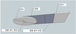
도 1은 본 발명의 예시적 실시 예의 개략도를 도시한다.
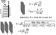
도 2는 임의의 설계 팩터 및 회로도 도면을 도시한다.
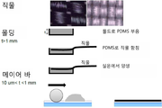
도 3은 예시적인 제조 공정의 개략도를 도시한다.
도 4는 패드-밧줄 연결을 위한 본 발명의 다양한 실시 예의 개략도를 도시한다.
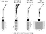
도 5는 "T-패드" 구조에 대하여, 순수 전단 하중하에서 지지되는 최대 힘을 특정하기 위한 예시적인 힘 대 변위측정량을 도시한다.
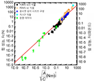
도 6은 다양한 "T-패드"구성, 살아있는 도마뱀, 비 직물 받침의 폴리머 코팅에 대해서 지지되는 예시적 최대 전단력을 면내(in-plane) 컴플라이언스(compliance)에 의해서 정규화된 계면 면적의 제곱근의 함수로서 도시한다.
도 7은 다양한 "T-패드"구성에 대한 피어(peel) 각도의 함수로서, 단위 폭 당 예시적인 파단력을 도시한다.
도 8은 다양한 표면상에서 하중을 지지하는 완전한 "T-패드" 구조의 임의의 예들을 도시한다.
도 9는 본 발명에 따른 접착제 패드 제조의 예시적인 실시 예를 개략적으로 도시한다.
도 10은 직물 접착제의 예시적인 이미지를 도시한다. (A)나일론 직물 PDMS 접착제,(B)탄소 섬유/케블라 평직 직물 PDMS 접착제, 및(C)단방향 탄소 섬유 폴리우레탄 접착제.
도 11은 폴리우레탄 예에 대하여, 주파수에 대한 계수의 바람직한 플롯을 도시한다.
도 12는 본 발명에 따른 접착제 패드를 제조하기 위한 성형 기술의 실시 예를 개략적으로 도시한다.
도 13은 제어변위시험(연장에 대한 하중 표시)의 예시적인 결과를 도시한다.
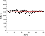
도 14는 주기적인 하중을 받은 폴리우레탄 접착제 패드의 반복성에 대한 예시적인 결과를 도시한다.
도 15는 136kg을 지지하는 폴리우레탄 접착제로서 수행된 정하중 시험을 도시한다.
도 16은 여러가지 기판들을 갖는 폴리우레탄 접착제로부터 얻어진 예시적인 하중 데이터를 도시한다.
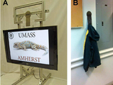
도 17은 (A) 42" 평판 TV를 지지하는 중앙 하중식 PDMS 접착제 패드와, (B) 건식 벽체상에서 후드 땀복을 지지하는 중앙 하중식 폴리우레탄 접착제 패드상에서 수행된 정하중 시험을 도시한다.
도 18(A)는 높은 성능과 쉬운 분리식의 접착제 패드에 대한 하중 각도 의존성에 관한 개략도를 도시한다.(B)는 단일 슬래브 접착제 패드에 비교되는 중앙 하중식 패드의 각도 의존성의 예시적인 결과를 도시하며, 여기서 상기 중앙 하중식 패드는 여전히 쉬운 분리를 허용하는 동시에, 다양한 하중 각도에 걸쳐서 높은 파단력을 유지한다. 1 shows a schematic diagram of an exemplary embodiment of the invention.
2 shows an optional design factor and schematic diagram.
3 shows a schematic of an exemplary manufacturing process.
4 shows a schematic diagram of various embodiments of the invention for a pad-rope connection.
FIG. 5 shows an exemplary force versus displacement measurement for specifying a maximum force supported under pure shear load, for a “T-pad” structure.
6 shows exemplary maximum shear forces supported for various “T-pad” configurations, live lizards, and non-woven fabric polymer coatings as a function of the square root of the interface area normalized by in-plane compliance. Illustrated.
7 shows exemplary fracture forces per unit width as a function of peer angle for various “T-pad” configurations.
8 shows certain examples of a complete “T-pad” structure supporting loads on various surfaces.
9 schematically illustrates an exemplary embodiment of an adhesive pad preparation in accordance with the present invention.
10 shows an exemplary image of a fabric adhesive. (A) nylon woven PDMS adhesive, (B) carbon fiber / Kevlar plain weave woven PDMS adhesive, and (C) unidirectional carbon fiber polyurethane adhesive.
11 shows a preferred plot of the coefficient against frequency, for the polyurethane example.
12 schematically illustrates an embodiment of a molding technique for producing an adhesive pad according to the present invention.
13 shows exemplary results of a control displacement test (load indication for extension).
14 shows exemplary results for repeatability of a polyurethane adhesive pad under periodic loading.
15 shows a static load test performed as a polyurethane adhesive supporting 136 kg.
16 shows exemplary load data obtained from polyurethane adhesive with various substrates.
FIG. 17 shows static load tests performed on (A) a centrally loaded PDMS adhesive pad supporting 42 "flat panel TVs, and (B) a centrally loaded polyurethane adhesive pad supporting hood sweatshirts on drywall.
18 (A) shows a schematic diagram of the load angle dependence for a high performance and easy detachable adhesive pad. (B) shows exemplary results of the angle dependence of the centrally loaded pad compared to a single slab adhesive pad. It is shown here that the centrally loaded pad still allows for easy detachment while maintaining high breaking force over various loading angles.
본 발명은 부분적으로, 새로운 설계, 시스템, 장치 및 관련 재료와 제조 방법의 발견에 기초하며, 이는 큰 접촉 표면, 높은 하중지지 성능, 쉬운 분리, 장시간 사용 및 반복 사용을 가능하게 한다. 특히, 본 발명은 접착제 시스템에 대해 고유하고, 이전에 알려지지 않은 접근 방식을 제공하며, 이는 기존의 PSA 시스템과는 다르고, 최근에 탐구된 도마뱀과 같은(gecko-like) 접착제와는 더욱 다르다.The present invention is based, in part, on the discovery of new designs, systems, devices and related materials and manufacturing methods, which allow for large contact surfaces, high load bearing performance, easy separation, long time use and repeated use. In particular, the present invention provides a unique, previously unknown approach to adhesive systems, which differs from existing PSA systems and is more different than recently explored gecko-like adhesives.
본 발명은 감압성 접착제 분야의 종래 기술과는 다르며, 적어도 본 발명에서는 제어를 달성하기 위해 감압성 접착제에서 수행하는 것과 같은 점탄성 특성에 의존하지는 않는다. 본 발명의 설계 및 시스템은 분리 시간과 에너지를 최소화할 수 있으며, 매우 높은 중량 하중을 지지하는 능력을 유지한다. 계면 접촉의 큰 영역은 부드러운 탄성 층과, 직물 층의 "드레이핑(draping)" 특성의 조합된 특성을 통해서 설계될 수 있다. 또한, 탄성적인 설계는 접착제 계면의 하중지지 성능의 저하없이, 반복적인 부착 및 분리 싸이클의 메커니즘을 제공한다.The present invention differs from the prior art in the field of pressure sensitive adhesives and at least does not rely on viscoelastic properties such as those performed in pressure sensitive adhesives to achieve control. The design and system of the present invention can minimize separation time and energy and maintain the ability to support very high weight loads. Large areas of interfacial contact can be designed through the combined nature of the soft elastic layer and the "draping" properties of the fabric layer. The resilient design also provides a mechanism for repeated attachment and detachment cycles without compromising the load bearing performance of the adhesive interface.
도마뱀-같은 접착제의 개발에서 종래와는 대조적으로, 여기에서 개시된 설계, 시스템 및 방법은 원하는 특성을 달성하기 위해 표면 섬유구조의 사용을 요구하지 않는다. 여기에서 기재된 원리에 따라, 당업자는 수직 상승이동의 도마뱀과 같은, 자연의 일반적인 예제에서 발가락과 다리 구조의 엔지니어링 설계를 모방할 수 있을 것이다.In contrast to the prior art in the development of lizard-like adhesives, the designs, systems and methods disclosed herein do not require the use of surface fibrous structures to achieve the desired properties. In accordance with the principles described herein, one of ordinary skill in the art will be able to mimic the engineering design of the toe and leg structures in a natural example, such as a lizard of vertical ascension.
본 발명과 종래 기술사이의 다른 중요한 차이점은, 다른 것들 중에서도, 연속적인 접합부에서의 회전 자유의 특정 설계, 탄성 재료 표면에 수직한 하중 방향으로의 낮은 휨 강성을 갖는 강성의 사양, 및 정상 및 전단 모두의 하중 방향하에서 제로(0)에 가까운 "예비-하중"(임의의 하중을 지지하기 위한 접착제/기판 계면을 설정하는 데 필요한 힘의 양을 말함)으로서 고성능 하중 지지를 얻을 수 있는 능력 등에 관련된다.Other important differences between the present invention and the prior art include, among others, the specific design of rotational freedom in continuous joints, the specification of rigidity with low bending stiffness in the direction of load perpendicular to the surface of the elastic material, and top and shear The ability to obtain high performance load support as a "pre-load" near zero in all directions of load (the amount of force required to establish the adhesive / substrate interface to support any load), etc. do.
본 발명의 한 가지 접근 방법에서, 여기에서 개시된 접착제 패드 시스템은 "건식" 접착제 패드 구조를 채택하고 있으며, 이는 가끔 "T-패드"로서 언급되고, 그것의 실시 예가 개략적으로 도 1에 도시되어 있다. 적절하게 설계된다면, 상기 T-패드 장치는 전단, 정상, 및 멀티 모드(즉, 피어(peel)) 하중하에서 높은 하중을 지지할 수 있고, 동시에 특별히 설계된 분리 상황하에서는, 분리(또는 떼어냄)에 대한 최소한의 힘과 에너지를 요구하게 된다.In one approach of the present invention, the adhesive pad system disclosed herein employs a “dry” adhesive pad structure, which is sometimes referred to as a “T-pad” and an embodiment thereof is schematically illustrated in FIG. 1. . If properly designed, the T-Pad device can support high loads under shear, normal, and multi-mode (i.e., peer) loads, and at the same time, under specially designed separation situations, at separation (or detachment) Will require minimal energy and energy.
접착제 장치의 기본 구조는 "패드"라 할 수 있고, 이는 후속적으로 밧줄(예를 들면, 인조 직물 밧줄)에 연결되며, 이는 "힘줄(tendon)"로도 불리운다. 상기 밧줄은 하중의 기본 축을 따라서 높은 강성을 유지해야 한다. 상기 밧줄과 패드 사이의 연결은 특별한 필요성에 따라서, 미리 정의된 크기, 방향 및 공간적 위치를 갖고, 분리 작동을 제어하며, 전단 및 정상 하중의 견고한 균형을 제공하도록 수정 될 수 있다. The basic structure of the adhesive device may be referred to as a "pad", which is subsequently connected to a rope (e.g., an artificial textile rope), which is also called a "tendon". The rope must maintain high rigidity along the basic axis of the load. The connection between the rope and the pad can be modified to have a predefined size, direction and spatial position, to control the separating operation and to provide a firm balance of shear and normal load, depending on the particular needs.
이러한 접근은 고분자 재료의 접착 특성과, 회전 자유의 적절한 보존, 접착 계면에 수직한 낮은 굴곡 계수, 및 하중 지지 방향에서의 높은 강성을 통한 통합적인 기계 설계의 독특한 조합을 나타낸다. 축적(scaling) 상관 관계가 본 발명자들에 의해서 개발되어, 크기 축적 및 형상의 일정 범위에 걸쳐서 재료 및 장치의 접착 성능을 이해하기 위한 프레임 작업을 제공한다(도 2 참조). 이러한 축적 상관 관계는 계면의 접착제 성능(Fc)이, 형상과 상기 계면의 재료 특성 모두에 따르는 3가지의 간단한 매개 변수들에 의해서 제어된다는 것을 제안한다. 다양한 기판에 부착할 수 있는 가역적 접착제를 설계하기 위하여, 계면 상호 작용(Gc)은 비-특정 반 데르 발스 힘에 의존하여야 하고, 이는 Gc에 비효과적인 제어 매개 변수를 부여한다. 따라서, 접착제 재료를 위한 Fc를 계량하기 위해서는, 상기 재료 시스템은 단순히 접촉 면적(A) 또는 시스템 컴플라이언스(C)에만 의존해서는 안되고, 반드시 A/C 비율을 증가시키는 특성을 개발해야 한다. 이것은 재료가 진정한 접촉을 위해서는 부드러워야 하지만, 높은 하중 지지를 달성하기 위해서는 견고해야만 한다는 과제를 제시한다. 부드러운 재료는 대규모의 접촉을 생성할 수 있지만, 하중이 가해질 때, 높은 컴플라이언스를 가지며, 반면에 견고한 재료는 광범위한 접촉을 생성할 수는 없으며; 이러한 두가지 경우는 A/C 비율상에 무의미한 효과를 초래한다. 현재의 본 발명은 A/C를 극대화하기 위한 메커니즘을 제공하고, 그리고 가장 중요하게는, 다른 응용 예에 대해서는 이러한 통제 매개 변수를 조정한다. 도 3에 개략적으로 설명된 바와 같이, 효율적이고 효과적인 제조 방법이 T-패드를 제작하는 데에 사용될 수 있다. 상기 방법은 직물의 표면에 탄력있는 탄성중합체의 얇은 층을 통합시키는 것을 포함한다.This approach represents a unique combination of adhesive properties of polymeric materials, proper preservation of rotational freedom, low bending modulus perpendicular to the bonding interface, and integrated mechanical design through high stiffness in the load bearing direction. Scaling correlations have been developed by the inventors to provide a framing operation to understand the adhesion performance of materials and devices over a range of size accumulations and shapes (see FIG. 2). This accumulation correlation suggests that the adhesive performance Fc of the interface is controlled by three simple parameters depending on both the shape and the material properties of the interface. In order to design a reversible adhesive that can attach to various substrates, the interfacial interaction (Gc) must rely on non-specific van der Waals forces, which impart ineffective control parameters to Gc. Thus, in order to meter Fc for adhesive material, the material system should not merely depend on contact area (A) or system compliance (C), but must develop characteristics that increase the A / C ratio. This presents the challenge that the material must be smooth for true contact, but must be robust to achieve high load support. Soft materials can produce large amounts of contact, but when loaded, they have high compliance, while hard materials cannot produce extensive contact; Both of these cases have insignificant effects on the A / C ratio. The present invention provides a mechanism for maximizing A / C, and most importantly, adjusts these control parameters for other applications. As outlined in FIG. 3, an efficient and effective manufacturing method can be used to fabricate the T-pad. The method includes incorporating a thin layer of elastic elastomer into the surface of the fabric.
상기 밧줄(힘줄)은 임의의 적절한 방법, 예를 들면 기존의 박음질, 바느질, 또는 접착제로 붙이는 등의 적절한 방법을 통해서 패드에 연결될 수 있으며, 이는 상기 연결의 크기적인, 위치적인 및 공간적인 배치를 쉽게 제어할 수 있다. 상기 연결은 충분한 하중 공유 및 하중 지지 성능을 제공해야 하며, 이는 바느질 패턴, 폭 및 길이를 통해서 제어될 수 있다. 적절한 바느질 패턴은 직선형 바느질, 지그재그 바느질, 다중 지그재그 바느질, 새틴 바느질, 벌집형 바느질, 사다리형 바느질, 이중 오버록 바느질과 십자형 바느질 등이 있다.The tether can be connected to the pad in any suitable manner, for example, by means of conventional stitching, sewing, or gluing, which can be used to determine the size, position and spatial arrangement of the connection. Easy to control The connection must provide sufficient load sharing and load bearing performance, which can be controlled through the sewing pattern, width and length. Suitable stitching patterns include straight stitch, zigzag stitch, multiple zigzag stitch, satin stitch, honeycomb stitch, ladder stitch, double overlock stitch and cross stitch.
예를 들면, 특별히 유익한 밧줄-패드 연결은 직선형 바느질로서, 패드의 한 축상에서 중심이 형성되고, 두 번째 패드 축에 대해 수직하게 대략 2/3 코드 길이만큼 연장되는 것이다. 상기 밧줄-패드 연결은 하중의 방향으로 높은 강성을 유지하면서 회전 자유를 유지해야 한다. 상기 밧줄-패드 연결은 상기 연결의 전체 길이를 따른 동일한 하중 공유를 바람직하게 유지하여야 한다. 상기 밧줄-패드 연결로부터 충분히 먼 거리에서, 상기 밧줄은 높은 휨 강성과 면-내 강성을 갖는 하중 지지 재료에 통합되어야 한다. 이 견고한 단자 재료는 때때로 "골격"("유지 성분")으로도 불리운다. 상기 밧줄-골격 사이의 연결은 바람직하게는 연속적이어서, 상기 연결의 길이에 따라서 동일한 하중 공유를 보장하여야 한다.A particularly advantageous rope-pad connection, for example, is straight stitching, which is centered on one axis of the pad and extends approximately 2/3 cord length perpendicular to the second pad axis. The rope-pad connection must maintain rotational freedom while maintaining high rigidity in the direction of the load. The tether-pad connection should preferably maintain the same load sharing along the entire length of the connection. At a sufficiently long distance from the tether-pad connection, the tether should be incorporated into a load bearing material having high flexural rigidity and in-plane rigidity. This rigid terminal material is sometimes referred to as "skeleton" ("maintenance component"). The connection between the tether-skeleton is preferably continuous, thus ensuring equal load sharing along the length of the connection.
본 발명은 하나의 T-패드 구조가 임의의 T-패드 구조나 유닛("T-표면"이라 함)들의 배열에 대해 독립적으로 또는 그와 함께 작동할 수 있는 설계를 포함하며, 이는, 예를 들면 회전가능한 자유 죠인트로서 하나 또는 그 이상의 방향에서 견고한 지지 기판에 장착될 수 있다. 임의의 응용 예에 대하여, 예를 들면, 큰 중량의 지지 선반, 상기 접착제 패드에 밧줄을 연결시키기 위한 여러 개의 접속 지점 등이 사용될 수 있다.The present invention encompasses designs in which one T-pad structure can operate independently or in conjunction with any T-pad structure or arrangement of units (referred to as "T-surfaces"), for example, For example, it can be mounted to a rigid support substrate in one or more directions as a rotatable free joint. For any application, for example, a heavy weight support shelf, several connection points for connecting a rope to the adhesive pad, and the like can be used.
도 4는 상기 밧줄-패드 연결을 위한 다양한 T-패드 구성의 개략도를 도시한다. 골격 연결은 표시되지 않았다. 단일 슬래브 연결은 연속적인 접착제 패드 및 지지 받침을 제공하며, 이는 많은 수의 개별적인 접착제 패드들 및 지지 받침들로 나눠질 수 있고, 여기서 여러 힘줄들이 서로 다른 구성(예를 들면, 경사진 길이의 시리즈 구성)을 생성하기 위해 사용된다. 상기 오프 에지(off edge) 힘줄 연결 및 중앙 하중식 패드 구성은 접착제 패드와 지지 받침을 구성하며, 여기서 평면 밧줄이 실질적으로 중앙에서 상기 접착제 패드에 부착되고, 상기 부착 길이는 T-패드의 경우에는 폭, 또는 상기 중앙 하중식 패드의 경우에는 일부 부분 또는 폭에 일치될 수 있다. 두가지 모두의 경우에서, 상기 접착제 패드에 연결된 밧줄은 상기 평면 밧줄과 접착제 패드 사이의 각도를 대략 0°내지 대략 359°사이에서 조정할 수 있다.4 shows a schematic of various T-pad configurations for the tether-pad connection. Skeletal linkages are not shown. A single slab connection provides for continuous adhesive pads and support supports, which can be divided into a large number of individual adhesive pads and support supports, where several tendons have different configurations (e.g., inclined length series). Configuration). The off edge tendon connection and centrally loaded pad configuration constitute an adhesive pad and a support base, wherein a flat tether is attached to the adhesive pad substantially at the center and the attachment length is in the case of a T-pad The width, or in the case of the centrally loaded pad, may be consistent with some portion or width. In both cases, the rope connected to the adhesive pad can adjust the angle between the flat rope and the adhesive pad between about 0 ° and about 359 °.
접착제 패드에서 사용될 수 있는 탄성 재료는, 실록산계 탄성중합체, 우레탄계 탄성중합체 및 아크릴레이트계 탄성중합체를 포함한다. 폴리디메틸실록산(PDMS)은 통상적으로 실리콘이라고 불리우는 고분자 유기규소 화합물의 그룹에 속한다. 광범위하게, 실리콘 기반의 유기 고분자를 사용한 PDMS는, 바람직한 유동성(또는 유량) 특성을 갖는다. PDMS는 일반적으로 불활성, 비독성과 불연성이다.Elastic materials that can be used in the adhesive pads include siloxane-based elastomers, urethane-based elastomers, and acrylate-based elastomers. Polydimethylsiloxane (PDMS) belongs to the group of high molecular organosilicon compounds commonly referred to as silicones. Broadly, PDMS using silicon-based organic polymers have desirable fluidity (or flow rate) properties. PDMS is generally inert, nontoxic and nonflammable.

폴리디메틸실록산 Polydimethylsiloxane
접착제 패드에서 사용될 수 있는 다른 탄성 재료는 폴리우레탄을 포함하며, 이는 우레탄(카르밤산염) 링크에 의해서 공유 원자가로 결합되는 유기 단위의 고분자이다.Other elastic materials that can be used in adhesive pads include polyurethanes, which are polymers of organic units that are bonded covalently by urethane (carbamate) links.

폴리우레탄 Polyurethane
우레탄 결합은 이소시아네이트 그룹, -N=C=O를, 하이드 록실 그룹, -OH에 반응시킴으로써 생산된다. 폴리우레탄은 촉매와 다른 첨가제의 존재하에, 폴리이소시아네이트와 다가 알콜(폴리올)의 중첨가 반응에 의해서 생성된다. 이 경우, 폴리이소시아네이트는 두 개 이상의 이소시아네이트 작용기를 가진 분자, R-(N=C=0)n ≥ 2 이고, 폴리올은 두 개 이상의 수산 작용기 그룹을 가진 분자, R'-(OH)n ≥ 2이다. 상기 반응 제품은 우레탄 결합, -RNHCOOR'- 을 포함하는 중합체이다. 폴리우레탄 단량체( "프리-폴리머")의 예로는 수산기 종료 분자들을 포함하며, 예를 들면 폴리에틸렌 글리콜, 폴리프로필렌 글리콜, 폴리테트라메틸렌 글리콜, 또는 비스페놀 A(수산기 함유 단량체) 및 지방족 또는 방향족계 이소시아네이트, 예를 들면 메틸렌 디페닐 디이소시아네이트, 톨루엔 디페닐 디이소시아네이트, 헥사메틸렌 디이소시아네이트, 이소포론 디이소시아네이트, 또는 다수의 이러한 단량체들의 조합으로부터 얻어진 폴리이소시아네이트(예를 들면, 메틸렌 디페닐 디이소시아네이트의 3개의 분자들은 3개의 이소시아네이트 작용기 그룹들을 포함하는 트리머를 형성)들이다.Urethane bonds are produced by reacting an isocyanate group, -N = C = O, with a hydroxyl group, -OH. Polyurethanes are produced by the polyaddition reaction of polyisocyanates with polyhydric alcohols (polyols) in the presence of catalysts and other additives. In this case, the polyisocyanate is a molecule having two or more isocyanate functionalities, R- (N = C = 0) n ≧ 2, and the polyol is a molecule having two or more hydroxyl functional groups, R ′-(OH) n ≧ 2 to be. The reaction product is a polymer comprising a urethane bond, -RNHCOOR'-. Examples of polyurethane monomers (“pre-polymers”) include hydroxyl end molecules, for example polyethylene glycol, polypropylene glycol, polytetramethylene glycol, or bisphenol A (hydroxyl containing monomers) and aliphatic or aromatic isocyanates, Three molecules of polyisocyanate (eg methylene diphenyl diisocyanate) obtained from, for example, methylene diphenyl diisocyanate, toluene diphenyl diisocyanate, hexamethylene diisocyanate, isophorone diisocyanate, or a combination of many of these monomers Are forming a trimer comprising three isocyanate functional groups).
일 측면에서, 본 발명은 일반적으로 분리가능한 표면-접착제 장치에 관한 것이다. 상기 장치는 접착제 패드 및 상기 접착제 패드에 연결된 밧줄 성분을 포함한다. 상기 접착제 패드는 다음을 포함한다: 높은 면내(in-plane) 강성을 갖는 평면 받침 층; 그리고 대상체 표면에 부착하기 위하여 적어도 한면에 접착 표면을 갖는 탄성 재료의 평면 층을 포함하고, 여기서 상기 탄성 재료는 상기 접착 표면의 적어도 반대쪽 측면상의 받침 층에 함침된다. 임의의 바람직한 실시 예에서, 상기 장치는 하중 지지를 위한 유지 성분을 추가적으로 포함한다. 상기 유지 성분은 대상체를 상기 장치에 연결하는 밧줄 성분에 탈착가능하다.In one aspect, the invention relates generally to a detachable surface-adhesive device. The device includes an adhesive pad and a tether component connected to the adhesive pad. The adhesive pads include: a planar backing layer having high in-plane stiffness; And a planar layer of elastic material having an adhesive surface on at least one side for attaching to the object surface, wherein the elastic material is impregnated in a backing layer on at least opposite side of the adhesive surface. In certain preferred embodiments, the device further comprises a retaining component for supporting the load. The retention component is detachable to a tether component connecting the subject to the device.
여기에서 사용된 용어 "받침"은, 언급된 층 또는 재료가 장치 구조의 배면(또는 마지막) 층인 상황을 포함하지만, 이에 제한되지 않음을 알아야 한다. 본 발명에 따르면, 받침 층은 구조 배열의 내부 층 또는 성분이 될 수 있다.As used herein, the term "support" includes, but is not limited to, the situation in which the mentioned layer or material is the back (or last) layer of the device structure. According to the invention, the backing layer can be an inner layer or component of the structural arrangement.
임의의 실시 에에서, 상기 접착제 패드는: 대상체 표면에 부착하기 위하여 일측면에 접착 표면을 갖는 탄성 재료의 평면층;과 높은 면-내 강성을 갖는 평면 받침 층;을 포함하고, 상기 받침 층은 상기 접착 표면의 반대 측면상에서 상기 탄성 재료의 층에 함침된다. In some embodiments, the adhesive pad comprises: a planar layer of elastic material having an adhesive surface on one side for attaching to an object surface; and a planar backing layer having high in-plane rigidity; The layer of elastic material is impregnated on the opposite side of the adhesive surface.
특정 실시 예에서, 상기 접착 표면은 미세하게 매끄럽다. 특정 실시 예에서, 상기 접착 표면은 미세하게 패턴이 형성되어 있다.In certain embodiments, the adhesive surface is finely smooth. In certain embodiments, the adhesive surface is finely patterned.
특정 실시 예에서, 상기 받침 층은 직물 받침 층이다.In certain embodiments, the backing layer is a fabric backing layer.
특정 실시 예에서, 상기 탄성 재료는 대략 0.01 ㎠ 내지 대략 1,000 ㎠의 접착 표면적(예를 들면, 0.01 ㎠ , 0.05 ㎠ , 0.1 ㎠ , 0.5 ㎠ , 1㎠ , 2 ㎠ , 5㎠ , 10㎠, 20 ㎠, 50 ㎠, 100 ㎠, 200 ㎠, 500 ㎠, 1,000 ㎠) 및 대략 0.001 cm 내지 대략 0.1 cm의 실질적으로 균일한 두께를 갖는다. 특정 실시 예에서, 상기 탄성 재료의 평면 층은 대략 0.01 ㎠ 보다 큰 부드러운 접착 표면적을 갖고, 그리고 대략 0.001 cm 이하의 실질적으로 균일한 두께를 가지고 있다. 특정 실시 예에서, 상기 탄성 재료의 평면 층은 대략 0.05 ㎠ 보다 큰 부드러운 접착 표면적을 갖고, 대략 0.005 cm 이하의 실질적으로 균일한 두께를 가지고 있다. 특정 실시 예에서, 상기 탄성 재료의 평면 층은 대략 0.1 ㎠ 보다 큰 부드러운 접착 표면적을 갖고, 대략 0.01 cm 이하의 실질적으로 균일한 두께를 가지고 있다. 특정 실시 예에서, 상기 탄성 재료의 평면 층은 대략 0.2 ㎠ 보다 큰 부드러운 접착 표면적을 갖고, 대략 0.5 cm 이하의 실질적으로 균일한 두께를 가지고 있다. 특정의 실시 예에서, 상기 탄성 재료의 평면 층은 대략 0.5 ㎠ 보다 큰 부드러운 접착 표면적을 갖고, 대략 0.2 cm 이하의 실질적으로 균일한 두께를 가지고 있다. 특정 실시 예에서, 상기 탄성 재료의 평면 층은 대략 1.0 ㎠ 보다 큰 부드러운 접착 표면적을 갖고, 대략 0.1 cm 이하의 실질적으로 균일한 두께를 가지고 있다. 특정 실시 예에서, 상기 탄성 재료의 평면 층은 대략 5.0 ㎠ 보다 큰 부드러운 접착 표면적을 갖고, 대략 0.05 cm 이하의 실질적으로 균일한 두께를 가지고 있다. 특정 실시 예에서, 상기 탄성 재료의 평면 층은 대략 10 ㎠ 보다 큰 부드러운 접착 표면적을 갖고, 대략 0.02 cm 이하의 실질적으로 균일한 두께를 가지고 있다. 특정 실시 예에서, 상기 탄성 재료의 평면 층은 대략 100 ㎠ 보다 큰 부드러운 접착 표면적을 갖고, 대략 0.01 cm 이하의 실질적으로 균일한 두께를 가지고 있다. 특정 실시 예에서, 상기 탄성 재료의 평면 층은 대략 10 ㎠ 내지 대략 100 ㎠ 의 부드러운 접착 표면적을 갖고, 대략 0.01 cm 내지 대략 0.05 cm의 실질적으로 균일한 두께를 가지고 있다. 특정 실시 예에서, 상기 탄성 재료의 평면 층은 대략 100 ㎠ 내지 대략 1,000 ㎠의 부드러운 접착 표면적을 갖고, 대략 0.05 cm 내지 대략 0.5 cm의 실질적으로 균일한 두께를 가지고 있다.In certain embodiments, the elastic material has an adhesive surface area of about 0.01
특정 실시 예에서, 상기 탄성 재료는 대략 0.05 MPa 내지 대략 50 MPa의 탄성을 갖는다. 특정 실시 예에서, 상기 탄성 재료는 대략 0.05 MPa 내지 대략 30 MPa의 탄성을 갖는다. 특정 실시 예에서, 상기 탄성 재료는 대략 0.05 MPa 내지 대략 10 MPa의 탄성을 갖는다. 특정 실시 예에서, 상기 탄성 재료는 대략 1 MPa 내지 대략 50 MPa의 탄성을 갖는다. 특정 실시 예에서, 상기 탄성 재료는 대략 1 MPa 내지 대략 30 MPa의 탄성을 갖는다. 특정 실시 예에서, 상기 탄성 재료는 대략 1 MPa 내지 대략 10 MPa의 탄성을 갖는다.In certain embodiments, the elastic material has an elasticity of about 0.05 MPa to about 50 MPa. In certain embodiments, the elastic material has an elasticity of about 0.05 MPa to about 30 MPa. In certain embodiments, the elastic material has an elasticity of about 0.05 MPa to about 10 MPa. In certain embodiments, the elastic material has an elasticity of about 1 MPa to about 50 MPa. In certain embodiments, the elastic material has an elasticity of about 1 MPa to about 30 MPa. In certain embodiments, the elastic material has an elasticity of about 1 MPa to about 10 MPa.
특정 실시 예에서, 상기 탄성 재료는 실록산계 탄성중합체를 포함한다. 특정 실시 예에서, 상기 탄성 재료는 우레탄계 탄성중합체를 포함한다. 특정 실시 예에서, 상기 탄성 재료는 아크릴레이트계 탄성중합체를 포함한다. 특정한 바람직한 실시 예에서, 상기 탄성 재료는 폴리디메틸실록산(PDMS)을 포함한다. 특정 실시 예에서, 상기 탄성 재료는 폴리우레탄, 예를 들면 지방족 또는 방향족계 폴리이소시아네이트와 수산기 종료 폴리에틸렌 글리콜의 중합으로부터 준비된 것을 포함한다. 임의의 적절한 재료가 사용될 수 있으며, 이는 스티렌-부타디엔-스티렌 탄성중합체 및 기타 열가역적 블록 공중합체 탄성중합체; 액정 탄성중합체; 천연 고무등을 포함한다.In certain embodiments, the elastic material comprises a siloxane-based elastomer. In certain embodiments, the elastic material comprises a urethane-based elastomer. In certain embodiments, the elastic material comprises an acrylate-based elastomer. In certain preferred embodiments, the elastic material comprises polydimethylsiloxane (PDMS). In certain embodiments, the elastic material comprises polyurethane, for example prepared from the polymerization of aliphatic or aromatic polyisocyanates with hydroxyl terminated polyethylene glycols. Any suitable material may be used, including styrene-butadiene-styrene elastomers and other thermoreversible block copolymer elastomers; Liquid crystal elastomers; Natural rubber is included.
특정 실시 예에서, 상기 직물 받침 층의 재료는 천연 직물 재료, 또는 인조 직물 재료를 포함한다. 특정 실시 예에서, 상기 직물 받침 층의 재료는 면, 대마, 모직, 실크, 대나무 스트링, 셀룰로오스, 황마 또는 피나와 같은 천연 직물재료를 포함한다. 특정 실시 예에서, 상기 직물 받침 층의 재료는 폴리에스테르, 스판덱스, 나일론, 탄소 섬유, 폴리아라미드, 탄소 섬유 폴리아라미드 하이브리드, 탄소 섬유 현무암 하이브리드, 유리섬유 또는 유리섬유 하이브리드들의 인조 직물을 포함한다. 특정한 바람직한 실시 예에서, 상기 직물 받침 층의 재질은 나일론, 탄소 섬유, 폴리아라미드, 탄소 섬유 및 폴리아라미드 하이브리드로 이루어진 그룹으로부터 선택된 재료를 포함한다.In certain embodiments, the material of the fabric backing layer comprises natural fabric material, or artificial fabric material. In certain embodiments, the material of the fabric backing layer includes natural textile materials such as cotton, hemp, wool, silk, bamboo strings, cellulose, jute or pina. In certain embodiments, the material of the fabric backing layer comprises an artificial fabric of polyester, spandex, nylon, carbon fiber, polyaramid, carbon fiber polyaramid hybrid, carbon fiber basalt hybrid, glass fiber or glass fiber hybrids. In certain preferred embodiments, the material of the fabric backing layer comprises a material selected from the group consisting of nylon, carbon fiber, polyaramid, carbon fiber and polyaramid hybrid.
특정 실시 예에서, 상기 장치는 100 ㎠ 또는 그 이상의 접착 표면적을 갖고, 접착 표면적의 100 ㎠ 당 적어도 1200 N 의 중량을 지지할 수 있다. 특정 실시 예에서, 상기 장치는 100 ㎠ 또는 그 이상의 접착 표면적을 갖고, 접착 표면적의 100 ㎠ 당 적어도 3150 N의 중량을 지지할 수 있다. 특정 실시 예에서, 상기 장치는 1 ㎠ 또는 그 이상의 접착 표면적을 갖고, 접착 표면적의 1 ㎠ 당 적어도 12.0 N 의 중량을 지지할 수 있다. 특정 실시 예에서, 상기 장치는 1 ㎠ 또는 그 이상의 접착 표면적을 갖고, 접착 표면적의 1 ㎠ 당 적어도 31.5 N 의 중량을 지지할 수 있다.In certain embodiments, the device has an adhesive surface area of 100
특정 실시 예에서, 상기 밧줄은 직물 재료이며, 예를 들면, 폴리에스터, 스판덱스, 나일론, 탄소 섬유, 폴리아라미드, 탄소 섬유 폴리아라미드 하이브리드, 탄소 섬유 현무암(basalt) 하이브리드, 유리섬유, 탄소 섬유 또는 유리섬유 하이브리드와 같은 인조 직물로부터, 그리고 면, 마, 울, 실크, 대나무 스트링, 셀룰로오스, 황마, 그리고 피나 등의 천연 직물로부터 선택된다. 특정 실시 예에서, 상기 밧줄은 비 직물 재료, 예를 들면 가죽, 금속 시트, 플라스틱 시트 또는 부직포 직물로부터 선택된다. 몇몇 실시 예에서, 상기 재료는 체인-링크 메쉬로부터 제작된다.In a particular embodiment, the rope is a textile material, for example polyester, spandex, nylon, carbon fiber, polyaramid, carbon fiber polyaramid hybrid, carbon fiber basalt hybrid, fiberglass, carbon fiber or glass Artificial fabrics such as fiber hybrids and natural fabrics such as cotton, hemp, wool, silk, bamboo strings, cellulose, jute, and pina. In certain embodiments, the rope is selected from non woven materials, such as leather, metal sheets, plastic sheets, or nonwoven fabrics. In some embodiments, the material is made from a chain-link mesh.
다른 측면에서, 본 발명은 일반적으로 분리가능한 표면-접착제 장치에 관한 것이다. 상기 장치는 다음을 포함한다: 탄성 재료를 포함하고, 대상체 표면과의 부착을 위해 일측면에 접착 표면을 갖고, 다른 측면에는 높은 면-내 강성을 갖는 받침 층을 갖는 평면 층을 포함하고, 상기 탄성 재료는 상기 받침 층에 함침되며; 상기 장치에 대상체를 연결하기 위하여 상기 받침 층에 탈착가능한 유지 성분을 포함한다. 상기 받침 층의 일부분은 상기 탄성 재료의 층 너머로 연장하여 상기 탄성 재료가 함침되지 않은 상기 받침 층의 일부 영역을 형성하고, 상기 유지 성분은 상기 탄성 재료가 함침되지 않은 상기 받침 층의 그러한 영역에서 상기 받침 층에 부착한다.In another aspect, the invention relates generally to a detachable surface-adhesive device. The apparatus includes: a planar layer comprising an elastic material, having a adhesive surface on one side for attachment to the object surface, and a backing layer on the other side having a backing layer with high in-plane stiffness, and An elastic material is impregnated into the backing layer; And a retaining component that is removable from the backing layer to connect the object to the device. A portion of the backing layer extends beyond the layer of elastic material to form a portion of the backing layer that is not impregnated with the elastic material, and the retaining component in the area of the backing layer where the elastic material is not impregnated. Attach to the backing layer.
특정 실시 예에서, 상기 탄성 재료는 상기 패드의 "뒷면"에서 상기 직물 층 너머로 연장할 수 있다. 이 설계는 직접적으로 상기 접착제 장치의 힘 성능에 관련되는 장치의 강성을 희생하지 않고, 균일한 접촉에 도움이 될 수 있다.In certain embodiments, the elastic material may extend beyond the fabric layer at the "back side" of the pad. This design can aid in uniform contact without sacrificing the stiffness of the device directly related to the force performance of the adhesive device.
또 다른 측면에서, 본 발명은 일반적으로 분리가능한 재사용 표면-접착제 장치에 관한 것이다. 상기 장치는 접착제 패드를 포함하고, 이는 대상체 표면과의 부착을 위해 일측면에 접착 표면을 갖는 탄성재료의 평면 층;과, 높은 면-내 강성을 갖는 평면 받침 층;을 포함하고, 상기 받침 층은 부드러운 접착 표면의 반대 측면상에서 상기 탄성 재료의 층으로 함침된다. 상기 장치는 추가적으로 상기 접착제 패드의 중앙에서 실질적으로 상기 접착제 패드에 부착하는 밧줄을 포함하고, 상기 평면 밧줄과 상기 접착제 패드의 사이에는 대략 0°내지 대략 359°범위의 각도 조정을 허용한다.In another aspect, the present invention generally relates to a detachable reusable surface-adhesive device. The apparatus includes an adhesive pad, comprising: a planar layer of elastic material having an adhesive surface on one side for attachment to an object surface; and a planar backing layer having high in-plane rigidity; Is impregnated with the layer of elastic material on the opposite side of the soft adhesive surface. The device additionally includes a tether that attaches substantially to the adhesive pad at the center of the adhesive pad and allows an angle adjustment in the range of approximately 0 ° to approximately 359 ° between the flat tether and the adhesive pad.
특정 실시 예에서, 상기 밧줄과 상기 접착제 패드 사이의 조절가능한 각도는 대략 0°내지 90°이며, 예를 들면, 15°, 30°, 45°, 60°이다. 다른 특정 실시 예에서, 상기 밧줄과 상기 접착제 패드 사이의 조절가능한 각도는 대략 90°내지 대략 120°이며, 예를 들면, 95°, 110°, 110°, 또는 115°이다. 다른 특정 실시 예에서, 상기 밧줄과 상기 접착제 패드 사이의 조절가능한 각도는 대략 120°내지 대략 360°이며, 예를 들면, 150°, 180°, 210°, 270°또는 300°이다.In certain embodiments, the adjustable angle between the tether and the adhesive pad is approximately 0 ° to 90 °, for example 15 °, 30 °, 45 °, 60 °. In another particular embodiment, the adjustable angle between the tether and the adhesive pad is approximately 90 ° to approximately 120 °, for example 95 °, 110 °, 110 °, or 115 °. In another particular embodiment, the adjustable angle between the tether and the adhesive pad is about 120 ° to about 360 °, for example 150 °, 180 °, 210 °, 270 ° or 300 °.
또 다른 측면에서, 본 발명은 일반적으로 분리가능한 표면-접착제 장치에 관한 것이다. 상기 장치는 접착제 패드를 포함하고, 이는 대상체 표면에 부착하기 위하여 일측면에 미세하게 매끄럽거나 패턴이 형성된 접착 표면을 갖는 탄성 재료의 평면층;과 높은 면-내 강성을 갖는 평면 직물 받침 층;을 포함하고, 상기 받침 층은 상기 접착 표면의 반대 측면상에서 상기 탄성 재료의 층에 함침된다. 상기 장치는 추가적으로 상기 접착제 패드에 연결된 밧줄 성분;과 하중 지지를 위한 유지 성분을 포함하고, 상기 유지 성분은 대상체를 상기 장치에 연결하기 위하여 상기 밧줄 성분에 부착가능하다.In another aspect, the invention relates generally to a detachable surface-adhesive device. The device comprises an adhesive pad, comprising: a flat layer of elastic material having a finely smooth or patterned adhesive surface on one side for attachment to an object surface; and a planar fabric backing layer having high in-plane rigidity; Wherein the backing layer is impregnated with the layer of elastic material on the opposite side of the adhesive surface. The device additionally includes a tether component connected to the adhesive pad; and a retaining component for load bearing, the retaining component being attachable to the tether component for connecting an object to the apparatus.
또 다른 측면에서, 본 발명은 일반적으로 표면상에 분리가능하게 중량을 지지하기 위한 방법에 관한 것이다. 상기 방법은 다음을 포함한다:(a) 접착제 패드를 포함하고, 대상체 표면에 부착하기 위하여 일측면에 미세하게 매끄러운 접착 표면을 갖는 탄성 재료의 평면층;과, 높은 면-내 강성을 갖는 평면 직물 받침 층을 포함하는 분리가능한 표면-접착제 장치를 제공하는 단계, 여기서 상기 직물 받침 층은 상기 부드러운 표면의 반대 측면상에서 상기 탄성 재료의 층에 함침되고; 직물 밧줄이 상기 접착제 패드에 연결되며; 그리고 하중 지지를 위한 유지 성분이 대상체를 상기 장치에 연결하기 위하여 상기 직물 밧줄에 부착가능하고; (b) 상기 유지 성분에 중량을 부착하는 단계를 포함한다.In another aspect, the present invention generally relates to a method for detachably supporting weight on a surface. The method comprises: (a) a planar layer of elastic material comprising an adhesive pad and having a finely smooth adhesive surface on one side for attachment to an object surface; and a planar fabric having high in-plane stiffness Providing a detachable surface-adhesive device comprising a backing layer, wherein the fabric backing layer is impregnated with the layer of elastic material on an opposite side of the soft surface; Fabric rope is connected to the adhesive pad; And a retaining component for load bearing is attachable to the fabric tether for connecting the object to the device; (b) attaching the weight to the fat or oil component.
또 다른 측면에서, 본 발명은 분리가능한 표면-접착제 장치를 제작하기 위한 방법에 관한 것이다. 상기 방법은 다음을 포함한다:(a) 탄성 재료를 제공하는 단계;(b) 직물 받침 시트를 제공하는 단계;(c) 상기 직물 받침 시트의 적어도 일부에 상기 탄성 재료를 함침시키도록 탄성 재료를 양생시켜서 부드러운 접착 표면을 갖는 상기 탄성 재료 층을 구비한 패드를 형성하는 단계; (d) 상기 직물 받침 시트에 중량-유지 성분을 장착시키는 단계를 포함한다. 상기 탄성 재료는 대략 0.05 MPa 내지 대략 50 MPa의 탄성을 가지고 있으며, 상기 탄성 재료의 층은 대략 0.0001 cm 내지 대략 0.1 cm의 두께를 가지고 있다.In another aspect, the invention relates to a method for fabricating a detachable surface-adhesive device. The method includes: (a) providing an elastic material; (b) providing a fabric backing sheet; (c) applying an elastic material to impregnate the elastic material in at least a portion of the fabric backing sheet. Curing to form a pad with the layer of elastic material having a smooth adhesive surface; (d) mounting a weight-bearing component to the fabric backing sheet. The elastic material has an elasticity of about 0.05 MPa to about 50 MPa and the layer of elastic material has a thickness of about 0.0001 cm to about 0.1 cm.
또 다른 측면에서, 본 발명은 일반적으로 분리가능한 표면-접착제 장치를 제작하기 위한 방법에 관한 것이다. 상기 방법은 다음을 포함한다:(a) 직물 받침 시트를 제공하고, 그것의 일측면상에 기판 층을 배치하는 단계; (b) 상기 직물 받침 시트의 다른 측면에, 스페이서-규정의 성형 영역을 제공하는 단계; (c) 상기 직물 받침 시트의 스페이서-규정의 성형 영역내로 탄성 재료를 추가시키는 단계; (d) 상기 탄성 재료를 미세하게 매끄럽거나 또는 패턴이 형성된 표면을 갖는 상부 커버로 덮는 단계;(e) 상기 상부 커버에 압력을 가하여서 상단 패드와 탄성 재료 사이에서 밀착된 계면을 형성하는 단계;(f) 상기 직물 받침 시트의 적어도 일부에 상기 탄성 재료를 함침시키도록 상기 탄성 재료를 양생시켜서 미세하게 매끄럽거나 또는 패턴이 형성된 접착 표면을 갖는 탄성 재료 층을 구비한 패드를 형성하는 단계; 그리고 (g) 상기 직물 받침 시트에 중량-유지 성분을 연결시키는 단계를 포함한다. 상기 탄성 재료는 대략 0.05 MPa 내지 대략 50 MPa의 탄성을 가지고 있으며, 상기 탄성 재료의 층은 대략 0.0001 cm 내지 대략 0.1 cm의 두께를 가지고 있다.In another aspect, the present invention generally relates to a method for manufacturing a detachable surface-adhesive device. The method includes: (a) providing a fabric backing sheet and disposing a substrate layer on one side thereof; (b) providing a spacer-defined forming area on the other side of the fabric backing sheet; (c) adding an elastic material into the spacer-defined forming region of the fabric backing sheet; (d) covering the elastic material with a top cover having a finely smooth or patterned surface; (e) applying pressure to the top cover to form a tight interface between the top pad and the elastic material (f) curing the elastic material to impregnate the elastic material in at least a portion of the fabric backing sheet to form a pad having a layer of elastic material having a finely smooth or patterned adhesive surface; And (g) coupling the weight-holding component to the fabric backing sheet. The elastic material has an elasticity of about 0.05 MPa to about 50 MPa and the layer of elastic material has a thickness of about 0.0001 cm to about 0.1 cm.
특정 실시 예에서, 손실 탄성 계수에 대한 저장 비율은, 관심있는 작동 온도에서 적어도 대략 10보다 크다(예를 들면, 15, 20, 또는 50보다 크다).In certain embodiments, the storage ratio for the loss modulus is greater than at least approximately 10 (eg greater than 15, 20, or 50) at the operating temperature of interest.
상기 탄성 재료의 층은 특정 응용예에서 요구하는 바와 같이, 임의의 크기와 형상일 수 있으며, 예를 들면, 그것은 실질적으로 원형의 외부 경계, 실질적으로 사각형 외부 경계, 실질적으로 타원형 외부 경계, 또는 실질적으로 불규칙한 외부 경계를 가질 수 있다.The layer of elastic material may be of any size and shape, as required by a particular application, for example, it may be a substantially circular outer boundary, a substantially rectangular outer boundary, a substantially elliptical outer boundary, or substantially It may have irregular outer boundaries.
여기에서 명시된 바와 같이, 특정 실시 예에서, 탄성 재료의 층은 둘, 셋, 넷 또는 그 이상의 분리된 보다 작은 탄성 재료 층 유닛 또는 구조물들을 포함한다. 상기 대상체 표면은 모든 적절한 표면일 수 있으며, 유리, 금속, 나무, 플라스틱, 종이, 판지, 또는 콘크리트 등을 포함한다.As noted herein, in certain embodiments, the layer of elastic material includes two, three, four, or more separate smaller elastic material layer units or structures. The object surface can be any suitable surface and includes glass, metal, wood, plastic, paper, cardboard, concrete, or the like.
하중의 반복된 부착 및 분리가, 순수한 전단 및 정상 하중 방향으로, 그리고 제어된 피어 각도하에서 시도되었고, 우리가 아는 어떠한 기존 제품과도 비교될 수 없는 성능을 나타내었다. 예를 들면, 실험 장치는 16 평방 인치의 T-패드로서 707파운드(44 PSI) 만큼을 지지할 수 있었고, 분리에 최소한의 힘이 필요하였으며, 동일한 패드 상에서 수많은 사이클 동안 반복적으로 실행되었고, 성능 저하는 무시할 정도였다. 또한, 접착제 패드 구조는 쉽게 비누와 물 또는 점탄성, 아크릴 테이프와 같은 입자 이동 재료로서 세척될 수 있다. 상기 분리 메커니즘은 특정 응용 예에 맞도록 여기에서 개시된 원리에 따라서 설계될 수 있다.Repeated attachment and detachment of loads was attempted in the direction of pure shear and normal loads, and under controlled peer angles, and exhibited unparalleled performance with any existing product we know. For example, the experimental setup was able to support as much as 707 pounds (44 PSI) as a 16-square inch T-pad, required minimal force for separation, was run repeatedly over many cycles on the same pad, and degraded performance. Was negligible. In addition, the adhesive pad structure can be easily washed with soap and water or particle transfer materials such as viscoelastic, acrylic tape. The separation mechanism can be designed according to the principles disclosed herein to suit a particular application.
본 발명의 통합된 접착제 패드 방식은, 광범위한 응용 예의 강력한 플랫폼을 제공한다. 예를 들면, 이러한 구조는 책, 디스플레이 및 가전 제품(텔레비전, 컴퓨터, 스테레오, 모니터, 스크린)을 위한 선반; 매달림 구조물, 자동차 트림, 다른 것들을 지지하는 데 사용될 수 있다. 또한, 현재의 설계는 유리, 금속, 나무 및 석고 등 다양한 재료로 만들어진 수직 표면 또는 오버행(overhangs) 상에서 클라이밍(climbing)을 용이하게 하도록 사용될 수 있다.The integrated adhesive pad approach of the present invention provides a powerful platform for a wide range of applications. For example, such a structure may include shelves for books, displays and consumer electronics (televisions, computers, stereos, monitors, screens); It can be used to support hanging structures, car trims, and the like. In addition, current designs can be used to facilitate climbing on vertical surfaces or overhangs made of various materials such as glass, metal, wood and gypsum.
시험 예(Examples)Test Examples
힘 대 변위 시험Force versus displacement test
도 5는 T-패드 구조에 대하여, 순수 전단 하중하에서 지지되는 최대 힘을 특정하기 위한 예시적인 힘 대 변위측정량을 도시한다.(직물 받침은 변경된다. 모든 결과는 16 in2 패드에 대하여, 범례에서 'T'로 표시된 두께를 변경시키면서 얻어진 것이었다.) 상기 실험은 단일 실험실 죠인트 형상의 인스트론 시험기에서 실행되었으며, 여기서, 부착은 상기 접착제 패드와 부드럽고 깨끗한 유리 기판 사이에서 이루어졌다. 연장은 10mm/분으로 조절되었고, 하중은 시험을 통해서 측정되었다. 최대 하중은 임계 파단 하중과 일치하는 것이고, 이는 도시된 바와 같은 직물 받침에 따라 변화한다.FIG. 5 shows an exemplary force versus displacement measure for specifying the maximum force supported under pure shear load, for a T-pad structure. (Fabric support is modified. All results are for 16 in 2 pads, The experiment was performed with varying thickness indicated by 'T' in the legend.) The experiment was performed on an Instron tester in the form of a single laboratory joint, where the attachment was made between the adhesive pad and a soft, clean glass substrate. The extension was adjusted to 10 mm / min and the load was measured through the test. The maximum load is consistent with the critical breaking load, which varies with the fabric bearing as shown.
도 6은 다양한 T-패드 구성, 천연 데이터(살아 있는 도마뱀을 포함하고, 도마뱀, 딱정벌레, 거미, 귀뚜라미, 그리고 파리들에 대한 다양한 연결 장치를 포함), 비 직물 받침의 폴리머 코팅에 대하여 지지되는 최대 전단력을 면내(in-plane) 컴플라이언스(compliance)에 의해서 정규화된 계면 면적의 제곱근의 함수로서 도시한다. 추세선은 예측된 스케일링 관계를 따르는 것이고, 이는 예측가능하게 최대 전단력 성능을 조정하는 능력을 보여준다.6 shows the maximum supported for various T-pad configurations, natural data (including live lizards and various connections to lizards, beetles, spiders, crickets, and flies), and polymer coatings of non-woven feet. Shear forces are plotted as a function of the square root of the interface area normalized by in-plane compliance. The trendline follows the predicted scaling relationship, which shows the ability to predictably adjust the maximum shear force performance.
파단력 시험Breaking force test
도 7은 다양한 "T-패드"구성(각각의 접착제 패드에 대한 총 접촉 면적은 10.8 ㎠ 이고, 중앙 하중식 패드 연결은 폭의 2/3이다)에 대한 피어(peel) 각도의 함수로서 단위 폭 당 파단력을 도시한다. 이는 쉬운 분리를 위하여 임계 각도를 조정하는 능력을 보여준다. 피어 실험이 깨끗한 유리상에서 10mm/분으로 인스트론 5500 R에서 수행되었으며, 그 적용 하중과 기판 사이의 각도는 0°와 90° 사이에서 변화되었다.FIG. 7 shows unit widths as a function of peer angle for various “T-pad” configurations (total contact area for each adhesive pad is 10.8
도 8은 다양한 표면상에서 하중을 지지하기 위한 완전한 "T-패드" 구조의 몇몇 간단한 예들을 도시한다. 동일한 나일론 직물 PDMS 접착제(A=16 in2 이고, 1 mm의 두께) 패드 구조가 모든 예제에서 사용된다.8 shows some simple examples of a complete “T-pad” structure for carrying loads on various surfaces. The same nylon woven PDMS adhesive (A = 16 in 2 , 1 mm thick) pad structure is used in all examples.
PDMS 접착제 패드의 제조Preparation of PDMS Adhesive Pads
도 9는 PDMS 접착제 패드 제조의 실시 예를 개략적으로 도시한다. (A) PDMS 접착제를 준비하기 위해, 몰드가 유리 슬라이드를 사용하여 제작되었다. 미양생되고, 기체가 제거된 PDMS 올리고머와 경화제(다우 코닝 실가드 184™)가 10:1의 비율(W/W)로 몰드에 부어졌다. 상기 몰드는 그 두께가 직물의 거칠기보다 크게 형성되어서, 제조 후 접착제상에 매끄러운 표면 마무리를 허용하도록 구성되었다. 탈기된(degassed) PDMS는 몰드로 부어지고, 확산이 허용되었으며, 직물이 적용되기 전에 6-8 분간 70℃에서 예비-양생이 실행되어, 그 다음 후속 양생 중에 직물을 지지하는 데 도움이 되도록 하였다.(B) 그 다음, 직물이 몰드상에 배치되어 미양생된 PDMS이 직물로 함침하도록 하였고, 3일 동안 실온에서 양생되었다. 하나의 조각으로 구성된 직물은 절단되어서, 그 폭이 몰드의 가장자리를 덮어서 지지를 제공할 수 있도록 하고, 그 길이는 충분하게 길어서 몰드를 덮고 "힘줄" 구조를 생성하였다. 상기 힘줄도 동일한 하중 공유를 제공하기 위하여 탄성중합체로 함침될 수 있다.9 schematically illustrates an embodiment of PDMS adhesive pad fabrication. (A) To prepare the PDMS adhesive, a mold was made using a glass slide. Uncured, degassed PDMS oligomer and curing agent (Dow Corning Sealguard 184 ™) were poured into the mold at a ratio of 10: 1 (W / W). The mold was constructed so that its thickness was greater than the roughness of the fabric, allowing for a smooth surface finish on the adhesive after manufacture. Degassed PDMS was poured into the mold, allowed to diffuse, and pre-cured at 70 ° C. for 6-8 minutes before the fabric was applied, to help support the fabric during subsequent curing. (B) The fabric was then placed on the mold to allow the uncured PDMS to be impregnated with the fabric and cured at room temperature for 3 days. The fabric consisting of one piece was cut so that its width covered the edge of the mold to provide support, and its length was sufficiently long to cover the mold and create a "tendon" structure. The tendon may also be impregnated with an elastomer to provide the same load sharing.
또 다른 실시 예에서, 상기 직물은 중앙 하중식 패드로 설계되어서, 직물 힘줄이 상기 접착제 패드 직물의 중앙에 바느질되었다. 이러한 구조에서, 상기 힘줄 구조는 PDMS로 함침되어서, 상기 직물이 후속의 하중적용 도중에 풀리지 않도록 보장하였다. 이는 상기 힘줄 및 접착제 패드 사이에 하나의 분리 시트를 배치함으로써 달성되었으며, 그 다음 힘줄을 가로질러서 PDMS를 확산시켰으며, 상기 함침됨 힘줄의 상부에 덮음용 분리 시트를 배치하였다. (C) 상기 PDMS가 양생된 후, 상기 직물 접착제는 몰드로부터 제거되고, 그리고 크기에 맞춰서 기계적으로 절단되었다. 2와 1/8 "의 두께로 이루어진 플라스틱 시트의 견고한 마운트("골격")가 시아노아크릴레이트 접착제를 사용하여 상기 힘줄의 바닥에 부착되었고, 그 다음 6 시간 동안 양생이 허용되었다.In another embodiment, the fabric is designed with a centrally loaded pad so that the fabric tendon is sewn in the center of the adhesive pad fabric. In this structure, the tendon structure was impregnated with PDMS to ensure that the fabric did not loosen during subsequent load application. This was achieved by placing one separating sheet between the tendon and the adhesive pad, then spreading the PDMS across the tendon, and placing a covering separating sheet on top of the impregnated tendon. (C) After the PDMS was cured, the fabric adhesive was removed from the mold and mechanically cut to size. A rigid mount (“skeleton”) of plastic sheet, 2 and 1/8 ”thick, was attached to the bottom of the tendon using cyanoacrylate adhesive and allowed to cure for 6 hours.
도 10은 (A) 나일론 직물 PDMS 접착제의 사진,(B) 탄소 섬유/케블라 평직 직물 PDMS 접착제, 및(C) 단방향 탄소 섬유 폴리우레탄 접착제 등의 예시적인 이미지를 도시한다. 중앙 열은 접착면이 위로 향한, 측면 프로파일의 주사 전자 현미경(SEM) 이미지를 보여주고, 오른쪽 열은 부드러운 접착 표면을 도시한다. 광학 사진에서 스케일 바는 5cm이며, SEM 이미지에서 모든 스케일 바는 500 ㎛ 이다.FIG. 10 shows exemplary images of (A) a photo of nylon woven PDMS adhesive, (B) carbon fiber / Kevlar plain woven PDMS adhesive, and (C) unidirectional carbon fiber polyurethane adhesive. The middle row shows the scanning electron microscope (SEM) image of the side profile, with the adhesive side facing up, and the right column shows the smooth adhesive surface. The scale bar is 5 cm in the optical picture and all scale bars are 500 μm in the SEM image.
폴리우레탄 접착제Polyurethane adhesive
폴리우레탄 접착제가, 수산기 종료 폴리에틸렌 글리콜, 폴리프로필렌 글리콜, 및/또는 폴리테트라메틸렌 글리콜의 작용기 그룹과, 지방족 또는 방향족계 폴리이소시아네이트 각각과 함께 1:1 비율로 추가하여 합성되었다. 폴리우레탄의 상용 키트가 본 응용 예에서 활용되었다.Polyurethane adhesives were synthesized by adding 1: 1 functional groups with hydroxyl group terminated polyethylene glycol, polypropylene glycol, and / or polytetramethylene glycol, together with aliphatic or aromatic polyisocyanates, respectively. Commercial kits of polyurethane have been utilized in this application.
도 11은 폴리우레탄 예에 대하여, 주파수에 대한 계수의 플롯을 도시한다.FIG. 11 shows a plot of the coefficient over frequency, for the polyurethane example.
저장 계수는 손실 계수보다 큰 크기의 대략적인 순서이며, 이는 상기 샘플이 주로 고체와 같은 탄성 특성을 갖는 다는 것을 보여준다. 또한 상기 계수는 주파수 크기의 두 체계에 걸쳐서 변화가 없다.The storage coefficient is an approximate order of magnitude greater than the loss coefficient, which shows that the sample mainly has elastic properties such as solids. In addition, the coefficient remains unchanged over two systems of frequency magnitude.
도 12는 개략적으로 폴리우레탄을 갖는 패드를 형성하는 성형 기술의 예를 도시한다. 폴리테트라플루오로에틸렌 기판 섬유의 상부에, 접착제 받침 층이 배치되었다. 저밀도 폴리에틸렌(LDPE) 스페이서가 폴리우레탄(PU)의 두께 제어를 허용할 수 있는 섬유의 상단에 배치되었고, 미양생된 PU 예비-중합체가 몰드 내에 부어졌다. 그 다음, 폴리디메틸실록산 패드가 유리 플레이트 상단에 배치되고, 최종적으로, 상기 시스템은 45 파운드 중량을 가졌다.12 schematically shows an example of a molding technique for forming a pad with polyurethane. On top of the polytetrafluoroethylene substrate fibers, an adhesive backing layer was disposed. Low density polyethylene (LDPE) spacers were placed on top of the fibers that could allow control of the thickness of polyurethane (PU) and uncured PU pre-polymer was poured into the mold. Then, a polydimethylsiloxane pad was placed on top of the glass plate and finally, the system weighed 45 pounds.
이러한 성형 기술을 활용하여, 부드러운 접착 표면(부드러운 PDMS 상부 층을 활용), 또는 표면 특성(패턴이 형성된 PDMS 상부 층을 활용)이 얻어질 수 있다. 상기 접착제의 두께는 LDPE 스페이서의 두께를 수정하여 변경될 수 있다. 이 방법은 접착제 패드의 대량 생산을 허용하는 닥터(doctor) 블레이드 시스템을 사용하여 작동하도록 변경될 수도 있다.Using this molding technique, a smooth adhesive surface (using a soft PDMS top layer), or surface characteristics (using a patterned PDMS top layer) can be obtained. The thickness of the adhesive can be changed by modifying the thickness of the LDPE spacer. This method may be modified to operate using a doctor blade system that allows for mass production of adhesive pads.
부하 시험Load test
접착제 패드의 샘플들이 인스트론 제어 변위 시험을 활용하여 시험되었다.Samples of adhesive pads were tested utilizing the Instron controlled displacement test.
기계적인 그립들이 인스트론 5500 R에 장착되었고, 유리 창이 크로스 헤드상에서 상기 그립에 부착되었고, 상기 접착제 패드는 하부 그립에 고정되었다. 그 다음, 상기 접착제 패드는 상기 유리에 부착되었으며, 상기 접착제가 유리로부터 분리될 때까지 10mm/분의 변위가 사용되었다. 이 시험은 평균 파단 력을 결정하고, 재사용성을 입증하기 위하여 여러 번 반복되었다. 도 13은 초기 부하 체계가 있고, 이 선의 기울기를 찾음으로써, 당업자는 접착제의 총 성능을 제어하는 접착제 시스템의 강성을 찾을 수 있다는 점을 도시한다. 이러한 폴리우레탄 접착제의 강성(따라서, 총 성능)은 이전에 기록된 강성 값보다 크다. 이 곡선의 정점이 총 성능(이 샘플에서는 ~2950 N)이다. 상기 피크 이후, 접착제가 유리로부터 분리되고, 기록된 하중 하락의 결과를 도시한다. 이 시험은 반복될 수 있으며, 시험의 100 사이클 이상을 통해서 좋은 재현성을 보여 주었다(도 14 참조).Mechanical grips were mounted on the Instron 5500 R, a glass window was attached to the grips on the cross head, and the adhesive pads were fixed to the lower grips. The adhesive pad was then attached to the glass and a displacement of 10 mm / min was used until the adhesive separated from the glass. This test was repeated several times to determine the average breaking force and to demonstrate reusability. FIG. 13 shows that there is an initial load regime and by looking for the slope of this line, one skilled in the art can find the stiffness of the adhesive system that controls the overall performance of the adhesive. The stiffness (and hence the total performance) of such polyurethane adhesives is greater than the previously recorded stiffness values. The peak of this curve is the total performance (-2950 N in this sample). After the peak, the adhesive separates from the glass and shows the result of the recorded load drop. This test can be repeated and showed good reproducibility through more than 100 cycles of the test (see FIG. 14).
정하중 시험이 이러한 폴리우레탄 접착제에서 수행되었다. 질량 136kg을 포함하는 바가 접착제 패드에 체인을 통해 연결되었고, 또한 풀리 시스템에 의해서 지지되었다. 상기 풀리 시스템을 사용하여, 상기 접착제가 상기 유리 부착물 설정 부분에 부착할 수 있을 때까지, 상기 중량이 상승되었다. 그 다음, 상기 풀리 시스템은 총 하중이 상기 접착제에 의해 지지될 때 까지, 하강되었다. 이러한 시험의 특정 결과가 도 15에 도시되어 있으며, 여기서 상기 시험은 유리 표면상에 136kg을 지지함으로써 실행되었다.Static load tests were performed on these polyurethane adhesives. A bar containing 136 kg of mass was connected via chain to the adhesive pad and also supported by the pulley system. Using the pulley system, the weight was increased until the adhesive could adhere to the glass deposit setting portion. The pulley system was then lowered until the total load was supported by the adhesive. Specific results of this test are shown in FIG. 15, where the test was performed by supporting 136 kg on the glass surface.
도 16에 도시된 바와 같이, 이러한 폴리우레탄 접착제는 다양한 기판상에서 사용될 수 있다. 이러한 결과는 이전의 하중 시험과 유사하게 수행되었지만, 그러나, 상기 유리 창은 새로운 재료로 대체되었고, 또는 새로운 재료는 유리 창의 표면에 부착되었다. 도 17은 정하중 시험을 도시하며, 이는 (A) 42" 평판 TV를 지지하는 16 in2 의 중앙 하중식 PDMS 접착제 패드와, (B) 건식 벽체상에서 후드 땀복을 지지하는 중앙 하중식 폴리우레탄 접착제 패드상에서 수행되었다. 도 18(A)는 높은 성능과 쉬운 분리식의 접착제 패드에 대한 하중 각도 의존성에 관한 개략도를 도시한다.(B)는 단일 슬래브 접착제 패드에 비교되는 중앙 하중식 패드의 각도 의존성의 결과를 도시하며, 여기서 상기 중앙 하중식 패드는 여전히 쉬운 분리를 허용하는 동시에, 다양한 하중 각도에 걸쳐서 높은 파단력을 유지한다. As shown in FIG. 16, such polyurethane adhesives can be used on a variety of substrates. This result was performed similar to the previous load test, however, the glass window was replaced with a new material, or the new material was attached to the surface of the glass window. FIG. 17 shows a static load test, (A) a 16 in 2 centrally loaded PDMS adhesive pad supporting 42 "flat panel TVs, and (B) a centrally loaded polyurethane adhesive pad supporting hood sweatshirts on drywall. 18 (A) shows a schematic diagram of the load angle dependence for a high performance and easy detachable adhesive pad. (B) shows the angle dependence of the centrally loaded pad compared to a single slab adhesive pad. The results show that the centrally loaded pad still allows for easy detachment while maintaining a high breaking force over various loading angles.
참조 지정(incorporation by reference)Incorporation by reference
다른 문서들, 예를 들면 특허, 특허 출원, 특허 출판물, 잡지, 책, 신문, 웹 콘텐츠에 대한 참조와 인용이 본 명세서내에서 이루어졌다. 그러한 모든 문서들은 모든 목적을 위해서 그 전체가 여기에 참조로 포함된 것이다.References and citations to other documents, such as patents, patent applications, patent publications, magazines, books, newspapers, web content, are made herein. All such documents are hereby incorporated by reference in their entirety for all purposes.
균등물Equalization
대표적인 예들은 본 발명의 설명을 돕기위해 의도된 것이며, 본 발명의 범위를 제한하고자 의도된 것이 아니며, 그렇게 해석되어서도 안된다. 실제로, 여기에서 도시되고 설명된 것에 추가적인, 본 발명과 그것의 많은 추가적인 실시 예들의 다양한 수정 내용들이, 본 명세서의 전체 내용과, 그 내부에 포함된 예제들, 과학 및 특허에 대한 참조들로부터 당업자들에게 명백해질 것이다. 상기 예들은 그것의 여러가지 실시 예들 및 그것의 균등물내에서, 본 발명의 구현에 적용될 수 있는 중요한 추가적인 정보, 예시 및 안내 등을 포함한다.
Representative examples are intended to aid the description of the present invention and are not intended to limit the scope of the present invention and should not be so interpreted. Indeed, various modifications of the present invention and its many additional embodiments, in addition to those shown and described herein, are to those skilled in the art from the entire contents of this specification and references to examples, science and patents contained therein. Will be evident to them. The examples include, within its various embodiments and equivalents, important additional information, examples, guidance, and the like, which can be applied to the implementation of the invention.
Claims (130)
높은 면내(in-plane) 강성을 갖는 평면 받침 층;
대상체 표면에 부착하기 위하여 적어도 한면에 접착 표면을 갖고, 탄성 재료가 상기 접착 표면의 적어도 반대쪽 측면상에서 상기 받침 층에 함침되는 탄성 재료의 평면 층;을 포함하며, 그리고
상기 접착제 패드에 부착되는 밧줄 성분;을 포함하는 분리가능한 표면-접착제 장치.And an adhesive pad, which:
A planar backing layer having high in-plane stiffness;
A planar layer of elastic material having an adhesive surface on at least one side for attaching to an object surface, wherein an elastic material is impregnated into the backing layer on at least the opposite side of the adhesive surface; and
And a tether component attached to the adhesive pad.
대상체 표면에 부착하기 위해 하나의 측면에 접착 표면을 갖는 탄성 재료의 평면 층; 및
높은 면-내 강성을 갖는 평면 받침 층;을 포함하고, 상기 받침 층은 상기 접착 표면의 반대 측면 상에서 상기 탄성 재료의 층에 함침되는 것임을 특징으로 하는 분리가능한 표면-접착제 장치.The method of claim 1, wherein the adhesive pad is:
A planar layer of elastic material having an adhesive surface on one side for attaching to the object surface; And
And a backing layer having high in-plane stiffness, wherein the backing layer is impregnated with the layer of elastic material on an opposite side of the adhesive surface.
장치에 대상체를 연결하기 위하여 상기 받침 층에 탈착가능한 유지 성분을 포함하며,
상기 받침 층의 일부분은 상기 탄성 재료의 층 너머로 연장하여 상기 탄성 재료가 함침되지 않은 상기 받침 층의 일부 영역을 형성하고, 상기 유지 성분은 상기 탄성 재료가 함침되지 않은 상기 받침 층의 그러한 영역에서 상기 받침 층에 부착하는 것을 포함하는 분리가능한 표면-접착제 장치.An elastic material, comprising a planar layer having an adhesive surface on one side for attachment to the object surface, and having a backing layer having a high in-plane stiffness on the other side, wherein the elastic material is impregnated into the backing layer Become; And
A removable component that is removable from the backing layer to connect the object to the device,
A portion of the backing layer extends beyond the layer of elastic material to form a portion of the backing layer that is not impregnated with the elastic material, and the retaining component in the area of the backing layer where the elastic material is not impregnated. A detachable surface-adhesive device comprising attaching to a backing layer.
대상체 표면과의 부착을 위해 일측면에 접착 표면을 갖는 탄성재료의 평면 층;과,
높은 면-내 강성을 갖는 평면 받침 층을 포함하고, 상기 받침 층은 상기 접착 표면의 반대 측면상에서 상기 탄성 재료의 층으로 함침되며;
모서리로부터 떨어져서 실질적으로 상기 접착제 패드의 중앙에서 상기 접착제 패드에 부착되는 밧줄을 포함하고, 상기 밧줄과 상기 접착제 패드의 사이에서 대략 0°내지 대략 359°의 각도 조정을 허용하는 분리가능한 재사용 표면-접착제 장치.And an adhesive pad, which:
A planar layer of elastic material having an adhesive surface on one side for attachment to the object surface; And,
A planar backing layer having high in-plane stiffness, the backing layer being impregnated with the layer of elastic material on the opposite side of the adhesive surface;
A detachable reusable surface-adhesive comprising a rope attached to the adhesive pad substantially at the center of the adhesive pad away from an edge and allowing an angle adjustment between approximately 0 ° and approximately 359 ° between the rope and the adhesive pad. Device.
대상체 표면에 부착하기 위하여 일측면에 미세하게 매끄럽거나 패턴이 형성된 접착 표면을 갖는 탄성 재료의 평면층;과
높은 면-내 강성을 갖는 평면 받침 층;을 포함하고, 상기 받침 층은 상기 접착 표면의 반대 측면상에서 상기 탄성 재료의 층에 함침되며;
상기 접착제 패드에 연결된 밧줄 성분;과
하중 지지를 위한 유지 성분을 포함하고, 상기 유지 성분은 대상체를 장치에 연결하기 위하여 상기 밧줄 성분에 부착가능하도록 구성된 분리가능한 표면-접착제 장치.And an adhesive pad, which:
A planar layer of elastic material having a finely smooth or patterned adhesive surface formed on one side for attachment to an object surface; and
A planar backing layer having high in-plane stiffness; the backing layer is impregnated with the layer of elastic material on an opposite side of the adhesive surface;
A rope component connected to the adhesive pad; and
And a retention component for load bearing, the retention component configured to be attachable to the tether component to connect an object to the device.
상기 접착제 패드에 연결되는 직물 밧줄을 포함하며; 그리고
하중 지지를 위한 유지 성분이 대상체를 상기 장치에 연결하기 위하여 상기 직물 밧줄에 부착가능하고; 그리고
상기 유지 성분에 중량을 부착하는 단계;를 포함하는 표면상에 분리가능하게 중량을 지지하기 위한 방법.Providing a detachable surface-adhesive device, wherein the device comprises an adhesive pad, which comprises a planar layer of elastic material having a finely smooth adhesive surface on one side for attachment to the object surface, and high in-plane stiffness A flat fabric backing layer having an impregnated layer of elastic material on opposite sides of the smooth surface;
A fabric tether connected to said adhesive pad; And
A retaining component for load bearing is attachable to the fabric tether to connect an object to the device; And
Attaching weight to the fat or oil component.
직물 받침 시트를 제공하는 단계;
상기 직물 받침 시트의 적어도 일부에 상기 탄성 재료를 함침시키도록 상기 탄성 재료를 양생시켜서 부드러운 접착 표면을 갖는 탄성 재료 층을 구비한 패드를 형성하는 단계;
상기 직물 받침 시트에 중량-유지 성분을 장착시키는 단계;를 포함하고,
상기 탄성 재료는 대략 0.05 MPa 내지 대략 50 MPa의 탄성을 가지고 있으며, 그리고 상기 탄성 재료의 층은 대략 0.01 cm 내지 대략 0.05 cm의 두께를 갖는 분리가능한 표면-접착제 장치의 제작방법.Providing an elastic material;
Providing a fabric backing sheet;
Curing the elastic material to impregnate the elastic material in at least a portion of the fabric backing sheet to form a pad having a layer of elastic material having a smooth adhesive surface;
Mounting a weight-holding component to the fabric backing sheet;
Wherein said elastic material has an elasticity of about 0.05 MPa to about 50 MPa, and said layer of elastic material has a thickness of about 0.01 cm to about 0.05 cm.
상기 직물 받침 시트의 다른 측면에, 스페이서-규정의 성형 영역을 제공하는 단계;
상기 직물 받침 시트의 상기 스페이서-규정의 성형 영역내로 탄성 재료를 추가시키는 단계;
상기 탄성 재료를 미세하게 매끄럽거나 또는 패턴이 형성된 표면을 갖는 상부 커버로 덮는 단계;
상기 상부 커버에 압력을 가하여서 상단 패드와 상기 탄성 재료 사이에서 밀착된 계면을 형성하는 단계;
상기 직물 받침 시트의 적어도 일부에 상기 탄성 재료를 함침시키도록 상기 탄성 재료를 양생시켜서 미세하게 매끄럽거나 또는 패턴이 형성된 접착 표면을 갖는 탄성 재료 층을 구비한 패드를 형성하는 단계; 그리고
상기 직물 받침 시트에 중량-유지 성분을 연결시키는 단계;를 포함하고,
상기 탄성 재료는 대략 0.05 MPa 내지 대략 50 MPa의 탄성을 가지고 있으며, 상기 탄성 재료의 층은 대략 0.01 cm 내지 대략 0.05 cm의 두께를 가지고 있는 분리가능한 표면-접착제 장치의 제작방법.Providing a fabric backing sheet and disposing a substrate layer on one side thereof;
Providing a spacer-defined forming area on the other side of the fabric backing sheet;
Adding an elastic material into the spacer-defined forming region of the fabric backing sheet;
Covering said elastic material with a top cover having a finely smooth or patterned surface;
Applying pressure to the top cover to form a tight interface between an upper pad and the elastic material;
Curing the elastic material to impregnate the elastic material in at least a portion of the fabric backing sheet to form a pad having a layer of elastic material having a finely smooth or patterned adhesive surface; And
Connecting the weight-holding component to the fabric backing sheet;
Wherein said elastic material has an elasticity of about 0.05 MPa to about 50 MPa, and said layer of elastic material has a thickness of about 0.01 cm to about 0.05 cm.
123. The method of claim 123, wherein the top cover has a finely patterned surface for forming an interface with the elastic material.
Applications Claiming Priority (3)
| Application Number | Priority Date | Filing Date | Title |
|---|---|---|---|
| US40554410P | 2010-10-21 | 2010-10-21 | |
| US61/405,544 | 2010-10-21 | ||
| PCT/US2011/057309 WO2012078249A2 (en) | 2010-10-21 | 2011-10-21 | High capacity easy release extended use adhesive devices |
Publications (1)
| Publication Number | Publication Date |
|---|---|
| KR20140035308A true KR20140035308A (en) | 2014-03-21 |
Family
ID=46207638
Family Applications (1)
| Application Number | Title | Priority Date | Filing Date |
|---|---|---|---|
| KR1020137012733A KR20140035308A (en) | 2010-10-21 | 2011-10-21 | High capacity easy release extended use adhesive devices |
Country Status (9)
| Country | Link |
|---|---|
| US (2) | US9574113B2 (en) |
| EP (1) | EP2630210A4 (en) |
| JP (2) | JP6021115B2 (en) |
| KR (1) | KR20140035308A (en) |
| CN (2) | CN106118537A (en) |
| AU (1) | AU2011338963A1 (en) |
| BR (1) | BR112013009688A2 (en) |
| CA (1) | CA2814374A1 (en) |
| WO (1) | WO2012078249A2 (en) |
Families Citing this family (30)
| Publication number | Priority date | Publication date | Assignee | Title |
|---|---|---|---|---|
| AU2011338963A1 (en) | 2010-10-21 | 2013-05-30 | University Of Massachusetts | High capacity easy release extended use adhesive devices |
| CN106313756A (en) * | 2012-01-19 | 2017-01-11 | 马萨诸塞大学 | Releasable adhesive devices |
| US9234381B2 (en) | 2013-01-07 | 2016-01-12 | WexEnergy LLC | Supplemental window for fenestration |
| US9845636B2 (en) | 2013-01-07 | 2017-12-19 | WexEnergy LLC | Frameless supplemental window for fenestration |
| US10196850B2 (en) | 2013-01-07 | 2019-02-05 | WexEnergy LLC | Frameless supplemental window for fenestration |
| US9691163B2 (en) | 2013-01-07 | 2017-06-27 | Wexenergy Innovations Llc | System and method of measuring distances related to an object utilizing ancillary objects |
| US10883303B2 (en) | 2013-01-07 | 2021-01-05 | WexEnergy LLC | Frameless supplemental window for fenestration |
| US9663983B2 (en) | 2013-01-07 | 2017-05-30 | WexEnergy LLC | Frameless supplemental window for fenestration incorporating infiltration blockers |
| CN104981526B (en) * | 2013-02-06 | 2017-07-04 | 马萨诸塞大学 | Load-bearing adhesion material with adjustable angle |
| WO2014152485A1 (en) | 2013-03-14 | 2014-09-25 | University Of Masssachusetts | Devices for application and load bearing and method of using the same |
| US9603419B2 (en) | 2013-03-15 | 2017-03-28 | University Of Massachusetts | High capacity easy release extended use adhesive closure devices |
| US9554674B2 (en) | 2013-10-08 | 2017-01-31 | Liberty Hardware Mfg. Corp. | Shower rod mounting assembly |
| JP2018500209A (en) * | 2014-12-10 | 2018-01-11 | ザ・チャールズ・スターク・ドレイパー・ラボラトリー・インコーポレイテッド | Polymer micro wedge and manufacturing method thereof |
| GB2535195B (en) * | 2015-02-12 | 2017-12-06 | Technip France | Pipeline tensioning apparatus and method |
| US11242905B2 (en) | 2015-07-31 | 2022-02-08 | Skydex Technologies, Inc. | Void cells with outwardly curved surfaces |
| US9833086B2 (en) | 2015-10-20 | 2017-12-05 | Liberty Hardware Mfg. Corp. | Planar display assembly |
| US10159364B2 (en) | 2015-10-20 | 2018-12-25 | Liberty Hardware Mfg. Corp. | Planar display assembly |
| US9924809B2 (en) | 2015-10-20 | 2018-03-27 | Liberty Hardware Mfg. Corp. | Retail display system and planar display assemblies |
| US10378676B2 (en) * | 2015-12-15 | 2019-08-13 | Sdb Ip Holdings, Llc | System, method, and apparatus for optimizing a timing of a flush valve |
| USD836366S1 (en) | 2016-02-05 | 2018-12-25 | Liberty Hardware Mfg. Corp. | Retail display rack |
| CA169807S (en) | 2016-02-05 | 2017-05-01 | Liberty Hardware Mfg Corp | Retail display |
| US11559148B2 (en) | 2016-02-05 | 2023-01-24 | Liberty Hardware Mfg. Corp. | Mirror display assembly and retail display system |
| KR101835218B1 (en) | 2016-06-14 | 2018-03-08 | 울산과학기술원 | Thermo-responsive smart adhesive pad |
| DE102017115704A1 (en) | 2016-07-12 | 2018-04-12 | Comprisetec Gmbh | Component for reversible adhesive adhesion to a smooth surface, kit and manufacturing process |
| US10681996B2 (en) | 2016-11-09 | 2020-06-16 | Liberty Hardware Mfg. Corp. | Planar display assembly |
| JP7212037B2 (en) | 2017-05-30 | 2023-01-24 | ウェクスエナジー リミテッド ライアビリティ カンパニー | Frameless auxiliary windows for daylight openings |
| WO2020188458A1 (en) | 2019-03-19 | 2020-09-24 | Invista North America S.A R.L. | Device for surface covering |
| CA3104075A1 (en) | 2020-01-08 | 2021-07-08 | Mixtiles Ltd. | Wall hanging decorative assembly having a flexible strip with removable adhesive and non-adhesive gap |
| US11667480B2 (en) | 2020-06-24 | 2023-06-06 | Rockwell Automation Technologies, Inc. | Systems and methods of applying reversible adhesion in a transportation system |
| US11898068B2 (en) | 2020-06-24 | 2024-02-13 | Rockwell Automation Technologies, Inc. | Reversible adhesive apparatus |
Family Cites Families (82)
| Publication number | Priority date | Publication date | Assignee | Title |
|---|---|---|---|---|
| US1739296A (en) | 1929-12-10 | Stbipe-painting device | ||
| US2884342A (en) * | 1956-04-02 | 1959-04-28 | Kendall & Co | Pressure sensitive adhesive sheet material |
| US3914484A (en) * | 1971-02-24 | 1975-10-21 | Dennison Mfg Co | Pressure sensitive adhesive labels and method of making |
| JPS5519141U (en) * | 1978-07-20 | 1980-02-06 | ||
| JPS5552721A (en) * | 1978-10-12 | 1980-04-17 | Nakamatsu Yoshiro | Soft hook |
| US4357198A (en) | 1981-08-17 | 1982-11-02 | Ezquerro Isaac E | Tape applicator |
| DE3303850A1 (en) * | 1982-02-04 | 1983-08-11 | Ausonia S.p.A., Monza | DETACHABLE ADHESIVE CONNECTION SYSTEM |
| IT1149738B (en) * | 1982-02-04 | 1986-12-10 | Ausonia Spa | SEPARATE PARTS JOINTING SYSTEM WITH POSSIBILITY TO JOIN AND REMOVE THE SAME PARTS REPEATEDLY |
| US4926526A (en) | 1983-09-12 | 1990-05-22 | Brown Christine C | Reusable bag closure |
| US4967740A (en) | 1986-06-11 | 1990-11-06 | Minnesota Mining And Manufacturing Company | Dispensable tapes |
| DE3638722A1 (en) | 1986-11-13 | 1988-05-26 | Pelikan Ag | DEVICE FOR APPLYING AN ADHESIVE FILM |
| US5049416A (en) | 1987-12-31 | 1991-09-17 | Union Oil Company Of California | Method for preparing pressure-sensitive adhesive articles |
| SE460263B (en) | 1988-03-04 | 1989-09-25 | Sprayway Maskin Ab | DEVICE FOR APPLICATION OF TABLE MATERIALS IN THE FORM OF A ROLL |
| US5516581A (en) * | 1990-12-20 | 1996-05-14 | Minnesota Mining And Manufacturing Company | Removable adhesive tape |
| US5269871A (en) | 1991-10-28 | 1993-12-14 | Minnesota Mining And Manufacturing Company | Tape applying device |
| US5747131A (en) | 1993-01-19 | 1998-05-05 | Minnesota Mining And Manufacturing Company | Process for bundling and/or fixing articles by use of an extensible plastic tape |
| DE69430376T2 (en) * | 1993-08-31 | 2002-11-14 | Minnesota Mining & Mfg | REMOVABLE FOAM ADHESIVE TAPE |
| US6403206B1 (en) | 1994-08-31 | 2002-06-11 | Minnesota Mining And Manufacturing Company | Removable foam adhesive tape |
| DE4339604C2 (en) | 1993-11-20 | 1996-06-05 | Beiersdorf Ag | Use of a section of adhesive film for a detachable bond |
| EP0813254B1 (en) * | 1996-06-14 | 2001-10-17 | Ngk Insulators, Ltd. | Method for producing ceramic diaphragm structure |
| US5865945A (en) | 1997-10-30 | 1999-02-02 | Mcconaughy; Drew B. | Pressure sensitive film applicator tool handle |
| US6972141B1 (en) * | 1997-12-12 | 2005-12-06 | 3M Innovative Properties Company | Removable adhesive tape laminate and separable fastener |
| US6120867A (en) * | 1998-01-27 | 2000-09-19 | 3M Innovative Properties Company | Removable tape laminate |
| US7181811B1 (en) | 1998-02-12 | 2007-02-27 | Board Of Trustees Operating Michigan State University | Micro-fastening system and method of manufacture |
| US6372341B1 (en) | 1998-04-27 | 2002-04-16 | 3M Innovative Properties Company | Tampa-indicating article for reusable substrates |
| DE69823518T2 (en) * | 1998-11-19 | 2005-04-07 | Minnesota Mining And Mfg. Co., St. Paul | Adhesive tape for a diaper closure system |
| US7132161B2 (en) | 1999-06-14 | 2006-11-07 | Energy Science Laboratories, Inc. | Fiber adhesive material |
| US6913075B1 (en) | 1999-06-14 | 2005-07-05 | Energy Science Laboratories, Inc. | Dendritic fiber material |
| US20040009353A1 (en) | 1999-06-14 | 2004-01-15 | Knowles Timothy R. | PCM/aligned fiber composite thermal interface |
| JP2001104118A (en) * | 1999-08-05 | 2001-04-17 | Chuo Kogei Kikaku Kk | Hook with adhesive sheet |
| US6302177B1 (en) | 1999-08-13 | 2001-10-16 | George Gruber | Tape dispenser system |
| US6558789B1 (en) * | 1999-11-10 | 2003-05-06 | 3M Innovative Properties Company | Removable tape laminate including a flexible non-stretchable support layer |
| US6737160B1 (en) | 1999-12-20 | 2004-05-18 | The Regents Of The University Of California | Adhesive microstructure and method of forming same |
| US8815385B2 (en) | 1999-12-20 | 2014-08-26 | The Regents Of The University Of California | Controlling peel strength of micron-scale structures |
| JP2001234149A (en) * | 2000-02-24 | 2001-08-28 | Sekisui Chem Co Ltd | Pressure-sensitive adhesive composition |
| US6569521B1 (en) | 2000-07-06 | 2003-05-27 | 3M Innovative Properties Company | Stretch releasing pressure sensitive adhesive tape and articles |
| US7575208B2 (en) | 2003-10-27 | 2009-08-18 | Yung-Huei Lan | Holding device with a securing sheet for mounting onto a wall |
| WO2002033274A1 (en) * | 2000-09-13 | 2002-04-25 | Lan Yung Huei | An adhesive sheet type holding device for mounting onto a wall |
| US7066182B1 (en) | 2000-09-27 | 2006-06-27 | 3M Innovative Properties Company | Conformable adhesive wound closures |
| US20020095130A1 (en) | 2000-11-28 | 2002-07-18 | Seitter Christopher R. | Adhesive garment closures |
| ATE493044T1 (en) | 2000-12-22 | 2011-01-15 | Binder Gottlieb Gmbh & Co Kg | METHOD FOR PRODUCING ADHESIVE CLOSURE PARTS |
| US7335271B2 (en) | 2002-01-02 | 2008-02-26 | Lewis & Clark College | Adhesive microstructure and method of forming same |
| US6872439B2 (en) | 2002-05-13 | 2005-03-29 | The Regents Of The University Of California | Adhesive microstructure and method of forming same |
| KR20050012756A (en) | 2002-05-29 | 2005-02-02 | 이 아이 듀폰 디 네모아 앤드 캄파니 | Fibrillar microstructure for conformal contact and adhesion |
| JP4292270B2 (en) * | 2002-07-30 | 2009-07-08 | フジコピアン株式会社 | Decorative fixing sheet |
| US7056409B2 (en) | 2003-04-17 | 2006-06-06 | Nanosys, Inc. | Structures, systems and methods for joining articles and materials and uses therefor |
| US7175723B2 (en) | 2003-10-03 | 2007-02-13 | The Regents Of The University Of California | Structure having nano-fibers on annular curved surface, method of making same and method of using same to adhere to a surface |
| US20050119640A1 (en) | 2003-10-03 | 2005-06-02 | The Regents Of The University Of California | Surgical instrument for adhering to tissues |
| US20050096613A1 (en) * | 2003-11-04 | 2005-05-05 | Carper James D. | Cling film fastening system for disposable soft goods |
| US7138177B2 (en) | 2003-11-21 | 2006-11-21 | 3M Innovative Properties Company | Adhesively mounted lever device |
| US7811272B2 (en) * | 2003-12-29 | 2010-10-12 | Kimberly-Clark Worldwide, Inc. | Nanofabricated gecko-like fasteners with adhesive hairs for disposable absorbent articles |
| JP2005298641A (en) * | 2004-04-09 | 2005-10-27 | Hitachi Chem Co Ltd | Pressure-sensitive adhesive film for surface protection |
| JP4718146B2 (en) * | 2004-09-01 | 2011-07-06 | 株式会社Shindo | Emulsion-type silicone pressure-sensitive adhesive composition for porous sheet and releasable pressure-sensitive adhesive sheet |
| WO2006046379A1 (en) | 2004-10-28 | 2006-05-04 | Shin-Etsu Engineering Co., Ltd. | Adhesive chuck device |
| US7799423B2 (en) | 2004-11-19 | 2010-09-21 | The Regents Of The University Of California | Nanostructured friction enhancement using fabricated microstructure |
| US8066088B2 (en) | 2004-12-09 | 2011-11-29 | The Board Of Trustees Of The Leland Stanford Junior University | Biologically inspired climbing device |
| EP1710286A1 (en) * | 2005-04-04 | 2006-10-11 | 3M Innovative Properties Company | Reinforcement Pad |
| US8398306B2 (en) | 2005-11-07 | 2013-03-19 | Kraft Foods Global Brands Llc | Flexible package with internal, resealable closure feature |
| DE102006010774A1 (en) | 2005-12-22 | 2007-07-05 | Graf, Michaela, Adeje | Closure for connecting two pieces of material e.g. materials layers, has two partially spaced catch elements whereby first catch element has fixing material and second catch element has centric break |
| US7762362B2 (en) * | 2006-04-17 | 2010-07-27 | The Board Of Trustees Of The Leland Stanford Junior University | Climbing with dry adhesives |
| US20080025822A1 (en) | 2006-04-17 | 2008-01-31 | Sangbae Kim | Device and method for handling an object of interest using a directional adhesive structure |
| DE102006038719A1 (en) | 2006-08-18 | 2008-02-21 | Tesa Ag | Pressure-sensitive adhesive strips for moisture-resistant, removable adhesive bonds |
| CN101528169A (en) * | 2006-08-31 | 2009-09-09 | 艾利丹尼森公司 | Stretchable laminate |
| BRPI0716371A2 (en) | 2006-08-31 | 2013-09-24 | Avery Dennison Corp | elastic diaper component |
| US8524092B2 (en) * | 2006-12-14 | 2013-09-03 | Carnegie Mellon University | Dry adhesives and methods for making dry adhesives |
| GB2451302B (en) | 2007-06-15 | 2012-10-24 | D G Capital Ltd | Zip closure system |
| US7824753B2 (en) * | 2007-06-28 | 2010-11-02 | 3M Innovative Properties Company | Removable adhesive tape with foldable pull tab |
| US7780810B2 (en) | 2007-07-16 | 2010-08-24 | RD & L Unique Products, LLC | Adhesion device for applying and releasing biomimetic microstructure adhesive from a contact surface |
| US20100044491A1 (en) | 2008-08-25 | 2010-02-25 | TraumaKwik Solutions L.L.P. | Rolled material applicator |
| CN201356127Y (en) | 2008-10-31 | 2009-12-09 | 郭大椿 | Adjusting belt and trousers provided therewith |
| JP5715573B2 (en) | 2008-12-31 | 2015-05-07 | スリーエム イノベイティブ プロパティズ カンパニー | Stretchable peelable adhesive tape |
| US8176959B2 (en) | 2009-01-12 | 2012-05-15 | Lamus Enterprises Inc. | Multi-functional tape applicator |
| US9221591B2 (en) | 2009-08-14 | 2015-12-29 | Cryovac, Inc. | Easy open and reclosable package with discrete laminate with die-cut |
| DE202010014239U1 (en) | 2010-10-14 | 2010-12-30 | Certoplast Vorwerk & Sohn Gmbh | Adhesive tape as well as hose cover made of the adhesive tape |
| AU2011338963A1 (en) | 2010-10-21 | 2013-05-30 | University Of Massachusetts | High capacity easy release extended use adhesive devices |
| US9765216B2 (en) | 2011-02-25 | 2017-09-19 | Carey & Co. | Dry adhesive |
| RU111405U1 (en) | 2011-03-25 | 2011-12-20 | Владимир Петрович Воинов | BELT LOCK (OPTIONS) |
| KR101473142B1 (en) | 2011-05-13 | 2014-12-15 | 밀란 그룹 | Dry adhesive assembly |
| CN106313756A (en) | 2012-01-19 | 2017-01-11 | 马萨诸塞大学 | Releasable adhesive devices |
| CN104981526B (en) | 2013-02-06 | 2017-07-04 | 马萨诸塞大学 | Load-bearing adhesion material with adjustable angle |
| WO2014152485A1 (en) | 2013-03-14 | 2014-09-25 | University Of Masssachusetts | Devices for application and load bearing and method of using the same |
| US9603419B2 (en) | 2013-03-15 | 2017-03-28 | University Of Massachusetts | High capacity easy release extended use adhesive closure devices |
-
2011
- 2011-10-21 AU AU2011338963A patent/AU2011338963A1/en not_active Abandoned
- 2011-10-21 CN CN201610591509.7A patent/CN106118537A/en active Pending
- 2011-10-21 WO PCT/US2011/057309 patent/WO2012078249A2/en active Application Filing
- 2011-10-21 CN CN201180061283.5A patent/CN103443226B/en not_active Expired - Fee Related
- 2011-10-21 CA CA2814374A patent/CA2814374A1/en not_active Abandoned
- 2011-10-21 JP JP2013535122A patent/JP6021115B2/en not_active Expired - Fee Related
- 2011-10-21 US US13/878,405 patent/US9574113B2/en active Active
- 2011-10-21 KR KR1020137012733A patent/KR20140035308A/en not_active Application Discontinuation
- 2011-10-21 EP EP11847209.1A patent/EP2630210A4/en not_active Withdrawn
- 2011-10-21 BR BR112013009688A patent/BR112013009688A2/en not_active IP Right Cessation
-
2016
- 2016-09-26 JP JP2016186404A patent/JP2017039940A/en active Pending
-
2017
- 2017-01-20 US US15/411,734 patent/US10150892B2/en active Active
Also Published As
| Publication number | Publication date |
|---|---|
| US9574113B2 (en) | 2017-02-21 |
| BR112013009688A2 (en) | 2018-05-08 |
| CA2814374A1 (en) | 2012-06-14 |
| JP6021115B2 (en) | 2016-11-02 |
| JP2014500341A (en) | 2014-01-09 |
| WO2012078249A3 (en) | 2012-09-20 |
| EP2630210A2 (en) | 2013-08-28 |
| CN106118537A (en) | 2016-11-16 |
| US10150892B2 (en) | 2018-12-11 |
| US20140030490A1 (en) | 2014-01-30 |
| US20170306189A1 (en) | 2017-10-26 |
| EP2630210A4 (en) | 2017-08-30 |
| CN103443226B (en) | 2016-08-17 |
| JP2017039940A (en) | 2017-02-23 |
| AU2011338963A1 (en) | 2013-05-30 |
| CN103443226A (en) | 2013-12-11 |
| WO2012078249A2 (en) | 2012-06-14 |
Similar Documents
| Publication | Publication Date | Title |
|---|---|---|
| KR20140035308A (en) | High capacity easy release extended use adhesive devices | |
| US10100229B2 (en) | Double- and multi-sided adhesive devices | |
| US10144195B2 (en) | Weight-bearing adhesives with adjustable angles | |
| King et al. | Creating gecko‐like adhesives for “real world” surfaces | |
| US10098419B2 (en) | High capacity easy release extended use adhesive closure devices | |
| DE60022101T2 (en) | RETRACTABLE SOLUBLE ADHESIVE TAPES AND ARTICLES | |
| US6407195B2 (en) | Tackified polydiorganosiloxane oligourea segmented copolymers and a process for making same | |
| JP3996189B2 (en) | Adhesive polydiorganosiloxane oligourea segmented copolymer and process for producing the copolymer | |
| WO1996035458A2 (en) | Tackified polydiorganosiloxane polyurea segmented copolymers and a process for making same | |
| EP0830428A2 (en) | Tackified polydiorganosiloxane polyurea segmented copolymers and a process for making same | |
| MXPA97008137A (en) | Segmented segmented polidiorganosiloxan-poliurea copolymer, adhesives, and process for your manufacture |
Legal Events
| Date | Code | Title | Description |
|---|---|---|---|
| WITN | Application deemed withdrawn, e.g. because no request for examination was filed or no examination fee was paid |