KR20140034720A - Method and apparatus for measuring oxidation-reduction potential - Google Patents
Method and apparatus for measuring oxidation-reduction potential Download PDFInfo
- Publication number
- KR20140034720A KR20140034720A KR1020137011236A KR20137011236A KR20140034720A KR 20140034720 A KR20140034720 A KR 20140034720A KR 1020137011236 A KR1020137011236 A KR 1020137011236A KR 20137011236 A KR20137011236 A KR 20137011236A KR 20140034720 A KR20140034720 A KR 20140034720A
- Authority
- KR
- South Korea
- Prior art keywords
- sample chamber
- lead
- reference cell
- sample
- test strip
- Prior art date
Links
Images


Classifications
-
- G—PHYSICS
- G01—MEASURING; TESTING
- G01N—INVESTIGATING OR ANALYSING MATERIALS BY DETERMINING THEIR CHEMICAL OR PHYSICAL PROPERTIES
- G01N27/00—Investigating or analysing materials by the use of electric, electrochemical, or magnetic means
- G01N27/26—Investigating or analysing materials by the use of electric, electrochemical, or magnetic means by investigating electrochemical variables; by using electrolysis or electrophoresis
- G01N27/28—Electrolytic cell components
- G01N27/30—Electrodes, e.g. test electrodes; Half-cells
- G01N27/327—Biochemical electrodes, e.g. electrical or mechanical details for in vitro measurements
- G01N27/3275—Sensing specific biomolecules, e.g. nucleic acid strands, based on an electrode surface reaction
- G01N27/3277—Sensing specific biomolecules, e.g. nucleic acid strands, based on an electrode surface reaction being a redox reaction, e.g. detection by cyclic voltammetry
-
- G—PHYSICS
- G01—MEASURING; TESTING
- G01N—INVESTIGATING OR ANALYSING MATERIALS BY DETERMINING THEIR CHEMICAL OR PHYSICAL PROPERTIES
- G01N27/00—Investigating or analysing materials by the use of electric, electrochemical, or magnetic means
- G01N27/26—Investigating or analysing materials by the use of electric, electrochemical, or magnetic means by investigating electrochemical variables; by using electrolysis or electrophoresis
- G01N27/28—Electrolytic cell components
- G01N27/30—Electrodes, e.g. test electrodes; Half-cells
- G01N27/301—Reference electrodes
-
- G—PHYSICS
- G01—MEASURING; TESTING
- G01N—INVESTIGATING OR ANALYSING MATERIALS BY DETERMINING THEIR CHEMICAL OR PHYSICAL PROPERTIES
- G01N27/00—Investigating or analysing materials by the use of electric, electrochemical, or magnetic means
- G01N27/26—Investigating or analysing materials by the use of electric, electrochemical, or magnetic means by investigating electrochemical variables; by using electrolysis or electrophoresis
- G01N27/416—Systems
- G01N27/4166—Systems measuring a particular property of an electrolyte
- G01N27/4168—Oxidation-reduction potential, e.g. for chlorination of water
-
- G—PHYSICS
- G01—MEASURING; TESTING
- G01N—INVESTIGATING OR ANALYSING MATERIALS BY DETERMINING THEIR CHEMICAL OR PHYSICAL PROPERTIES
- G01N33/00—Investigating or analysing materials by specific methods not covered by groups G01N1/00 - G01N31/00
- G01N33/48—Biological material, e.g. blood, urine; Haemocytometers
- G01N33/483—Physical analysis of biological material
- G01N33/487—Physical analysis of biological material of liquid biological material
- G01N33/49—Blood
-
- G—PHYSICS
- G01—MEASURING; TESTING
- G01N—INVESTIGATING OR ANALYSING MATERIALS BY DETERMINING THEIR CHEMICAL OR PHYSICAL PROPERTIES
- G01N27/00—Investigating or analysing materials by the use of electric, electrochemical, or magnetic means
- G01N27/26—Investigating or analysing materials by the use of electric, electrochemical, or magnetic means by investigating electrochemical variables; by using electrolysis or electrophoresis
- G01N27/28—Electrolytic cell components
- G01N27/30—Electrodes, e.g. test electrodes; Half-cells
- G01N27/327—Biochemical electrodes, e.g. electrical or mechanical details for in vitro measurements
- G01N27/3271—Amperometric enzyme electrodes for analytes in body fluids, e.g. glucose in blood
- G01N27/3272—Test elements therefor, i.e. disposable laminated substrates with electrodes, reagent and channels
-
- G—PHYSICS
- G01—MEASURING; TESTING
- G01N—INVESTIGATING OR ANALYSING MATERIALS BY DETERMINING THEIR CHEMICAL OR PHYSICAL PROPERTIES
- G01N27/00—Investigating or analysing materials by the use of electric, electrochemical, or magnetic means
- G01N27/26—Investigating or analysing materials by the use of electric, electrochemical, or magnetic means by investigating electrochemical variables; by using electrolysis or electrophoresis
- G01N27/403—Cells and electrode assemblies
Landscapes
- Health & Medical Sciences (AREA)
- Life Sciences & Earth Sciences (AREA)
- Chemical & Material Sciences (AREA)
- Physics & Mathematics (AREA)
- Molecular Biology (AREA)
- Pathology (AREA)
- Analytical Chemistry (AREA)
- Biochemistry (AREA)
- General Health & Medical Sciences (AREA)
- General Physics & Mathematics (AREA)
- Immunology (AREA)
- Engineering & Computer Science (AREA)
- Chemical Kinetics & Catalysis (AREA)
- Electrochemistry (AREA)
- Biomedical Technology (AREA)
- Hematology (AREA)
- Ecology (AREA)
- Biophysics (AREA)
- Urology & Nephrology (AREA)
- Food Science & Technology (AREA)
- Medicinal Chemistry (AREA)
- Spectroscopy & Molecular Physics (AREA)
- Investigating Or Analysing Biological Materials (AREA)
- Investigating Or Analyzing Materials By The Use Of Electric Means (AREA)
- Sampling And Sample Adjustment (AREA)
- Apparatus Associated With Microorganisms And Enzymes (AREA)
Abstract
액체 시료의 산화-환원 전위를 측정하기 위한 방법 및 시스템이 제겅된다. 상기 시스템은 액체 시료를 수용하기 위한 시료 챔버를 구비한 검사 스트립을 포함한다. 상기 시료 챔버는 필터막과 연결될 수 있다. 상기 검사 스트립은 또한 기준 셀을 포함한다. 시료 챔버에 위치한 액체 시료의 산화-환원 전위는 시료 챔버 및 기준 셀과 전기적으로 접촉하는 기준 리드와 전기적으로 접촉하는 검사 리드에 상호연결된 검출 장치에 의하여 확인될 수 있다. 시료 챔버에 위차한 액체 시료와 기준 셀의 전기적 접촉은 브리지에 의하여 이루어질 수 있다. 상기 브리지는 예를 들어 액체 시료 또는 전해질 젤에 의하여 습윤화된 필터지와 같은 필터부를 포함할 수 있다. 산화-환원 전위는 검사 스트립의 검사 리드 및 기준 리드 사이의 전기적 전위로서 확인될 수 있다.Methods and systems are provided for measuring the redox potential of a liquid sample. The system includes a test strip having a sample chamber for receiving a liquid sample. The sample chamber may be connected to the filter membrane. The test strip also includes a reference cell. The redox potential of the liquid sample located in the sample chamber can be identified by a detection device interconnected to the test lead in electrical contact with the reference lead in electrical contact with the sample chamber and the reference cell. Electrical contact between the liquid sample and the reference cell in the sample chamber may be achieved by a bridge. The bridge may comprise a filter portion, for example a filter paper wetted by a liquid sample or electrolyte gel. The redox potential can be identified as the electrical potential between the test lead and the reference lead of the test strip.
Description
본 발명은 액체 시료의 산화-환원 전위를 측정하는 방법 및 장치에 대한 것이다.
The present invention is directed to a method and apparatus for measuring the redox potential of a liquid sample.
본 출원은 2011년 2월 28일자로 출원된 미국 가출원 출원번호 61/447,568의 이익을 주장하며, 이에 개시된 전체는 본 명세서에 참조로 포함된다.
This application claims the benefit of US Provisional Application No. 61 / 447,568, filed February 28, 2011, the entirety of which is hereby incorporated by reference.
플라스마 그리고 세럼과 같은 전혈 및 혈액 성분은 산화-환원 전위(ORP)를 갖는다. 임상학적으로 혈액 및 플라스마 및 세럼의 ORP는 동물의 산화 상태의 진단용 아세이를 제공한다. 특히, 연구자들은 혈액 및 플라스마 및 세럼의 ORP가 건강 및 질병에 연관되어 있다고 결론 내린 바 있다.
Whole blood and blood components such as plasma and serum have redox potentials (ORPs). Clinically, ORP in blood and plasma and serum provide diagnostic assays of the oxidized state of animals. In particular, the researchers concluded that ORP in blood and plasma and serum are linked to health and disease.
산화환원시스템, 혹은 레독스(redox) 시스템은 다음의 공식에 따라서 전자들이 환원제에서 산화제로 이동하는 것을 포함한다:Redox systems, or redox systems, involve the transfer of electrons from a reducing agent to an oxidant according to the following formula:
산화제 + ne- ↔ 환원제 (1)Oxidizing agent + n e - ↔ reducing agent (1)
여기서 ne- 는 이동한 전자수와 같다. 평형 상태에서, 환원 전위(E), 혹은 산화-환원 전위(ORP)는 Nernst-Peters 공식에 따라서 산출된다:Where n e - is equal to the number of electrons moved. At equilibrium, the reduction potential (E), or redox potential (ORP), is calculated according to the Nernst-Peters formula:
E(ORP) = Eo - RT/nF ln [환원제]/[산화제] (2)
E (ORP) = E o RT / n F ln [reducing agent] / [oxidizing agent] (2)
여기서 R(가스 상수), T(켈빈 온도), F(패러데이 상수)는 상수들이다. Eo는 수소전극에 대하여 측정된 레독스 시스템의 표준 전위이고, 임의적으로 Eo는 0 볼트, n은 이동한 전자의 수이다. 따라서, ORP는 환원제와 산화제의 전체 농도에 좌우되고, ORP는 특정시스템에서 전체 환원제와 산화제 사이 평형의 통합된 측정치이다. 이렇게 ORP는 환자의 체액 혹은 조직의 전체적인 산화 상태 측정치를 제공한다.
Where R (gas constant), T (Kelvin temperature) and F (Faraday constant) are constants. E o is the standard potential of the redox system measured for the hydrogen electrode, and optionally E o is 0 volts, n is the number of electrons moved. Thus, ORP depends on the total concentration of reducing and oxidizing agents, and ORP is an integrated measure of the equilibrium between total reducing and oxidizing agents in a particular system. ORP thus provides a measure of the overall oxidation state of the patient's fluids or tissues.
정상치의 ORP 보다 현저히 높은 ORP 측정치는 산화 스트레스가 존재함을 의미한다. 산화 스트레스는 많은 질병에 연관되어 왔으며, 모든 치명적인 질병의 종류에서 발생하는 것으로 나타나고 있다. 따라서, 정상치보다 현저히 높은 ORP 수준은 질병 그리고 치명적인 질병이 존재함을 의미한다. 정상치의 ORP 와 같거나 낮은 ORP 측정치는 산화 스트레스가 존재하지 않는다는 것 그리고 질병 혹은 치명적인 질병이 존재하지 않음을 의미한다. 따라서, 환자의 ORP 수준은 의사 혹은 수의사가 질병, 특히 중증 질환의 유무를 진단 혹은 배제하는 도구로 사용될 수 있다. 시간에 따른 ORP의 순차적(sequential) 측정은 질병의 진전상황 그리고 질병 치료의 효과 혹은 효과부족을 확인하는데 사용될 수 있다. 만약 환자의 ORP가 치료 후에 감소하거나 혹은 특히 치료에도 불구하고 증가한다면, 이는 부정적인 예측을 의미할 수 있고, 그리고 보다 강도 높은 및/또는 추가적인 및/또는 다른 치료방법이 필요하다는 것을 나타낼 수 있다. 심근경색 증상을 겪고 있는 환자처럼 환자가 직접 측정을 하는 경우에는, ORP수준은 환자가 의사의 진료가 필요하거나 혹은 치료받기 위해 응급실로 즉시 가야 할 필요성을 나타낼 수 있다.
Significantly higher ORP measurements than normal ORP indicate the presence of oxidative stress. Oxidative stress has been linked to many diseases and appears to occur in all types of fatal diseases. Thus, significantly higher ORP levels than normal mean that the disease and fatal disease are present. ORP measurements equal to or lower than normal ORP mean no oxidative stress and no disease or fatal disease. Therefore, the ORP level of the patient can be used as a tool for the doctor or veterinarian to diagnose or exclude the presence of a disease, especially a serious disease. Sequential measurement of ORP over time can be used to identify disease progress and the effectiveness or lack of effectiveness of disease treatment. If the patient's ORP decreases after treatment or especially increases despite treatment, this may mean a negative prediction and may indicate that more intense and / or additional and / or other treatments are needed. If the patient is directly measuring, such as a patient suffering from myocardial infarction, the ORP level may indicate that the patient needs to see a doctor or go to the emergency room immediately for treatment.
산화 스트레스는 활성 산소 및 활성 질소종의 생성이 높아지거나 혹은 내인성 보호 항산화능(endogenous protective antioxidative capacity)이 감소하는데 기인한다. 산화 스트레스는 다양한 질병과 노화에 관련이 되며, 모든 종류의 중증질환에서 발견되고 있다 (예를 들어, Veglia et al., Biomarkers, 11(6): 562-573 (2006); Roth et al., Current Opinion in Clinical Nutrition and Metabolic Care, 7:161-168 (2004); U.S. Patent No. 5,290,519 and U.S. Patent Publication No. 2005/0142613 참조) . 다수의 연구에서 중증질환환자의 산화 상태와 환자에 대한 결과 사이에 밀접한 연계성이 나타나 있다 (Roth et al., Current Opinion in Clinical Nutrition and Metabolic Care, 7:161-168 (2004) 참조).
Oxidative stress is due to increased production of free radicals and reactive nitrogen species, or reduced endogenous protective antioxidative capacity. Oxidative stress is associated with a variety of diseases and aging and is found in all types of severe disease (eg, Veglia et al., Biomarkers , 11 (6) : 562-573 (2006); Roth et al. Current Opinion in Clinical Nutrition and Metabolic Care , 7 : 161-168 (2004); U.S. Pat. 5,290,519 and US Patent Publication No. 2005/0142613). Many studies have shown a close link between the oxidative status of severely ill patients and outcomes for patients (Roth et al., Current Opinion in Clinical Nutrition and Metabolic Care , 7 : 161-168 (2004)).
환자의 산화 스트레스는 다양한 개별 마커를 측정하면서 평가되고 있다(예를 들어, Veglia et al., Biomarkers, 11(6): 562-573 (2006); Roth et al., Current Opinion in Clinical Nutrition and Metabolic Care, 7:161-168 (2004); U.S. Patent No. 5,290,519 and U.S. Patent Publication No. 2005/0142613). 그러나, 이러한 측정은 때로 신뢰성이 없으며, 환자의 산화상태의 측정이 다양한 값이거나 상충되어서 제공된다(Veglia et al., Biomarkers, 11(6): 562-573 (2006); Roth et al., Current Opinion in Clinical Nutrition and Metabolic Care, 7:161-168 (2004)). 환자의 전반적인 산화 상태를 점수화하거나 다른 방법으로 평가하는데 활용되는 다수의 마커 측정은 단일 마커에 의한 측정을 사용하는 문제점을 극복하도록 개발되었다(Veglia et al., Biomarkers, 11(6): 562-573 (2006); Roth et al., Current Opinion in Clinical Nutrition and Metabolic Care, 7:161-168 (2004) 참조). 단일 마커에 의한 측정보다는 이러한 접근법이 더욱 신뢰성 있고 세밀한 측정이 가능하지만, 이러한 접근법은 복잡하고 시간이 많이 소비된다. 따라서, 환자의 전반적인 산화 상태를 신뢰성 있게 측정하기 위한 더욱 간편하고 빠른 방법이 필요하다.
Oxidative stress in patients is assessed by measuring various individual markers (eg, Veglia et al., Biomarkers , 11 (6) : 562-573 (2006); Roth et al., Current Opinion in Clinical Nutrition and Metabolic Care , 7 : 161-168 (2004); U.S. Pat. 5,290,519 and US Patent Publication No. 2005/0142613). However, these measurements are sometimes unreliable and are provided because the measurement of the patient's oxidation status is variable or conflicting (Veglia et al., Biomarkers , 11 (6) : 562-573 (2006); Roth et al., Current Opinion in Clinical Nutrition and Metabolic Care , 7 : 161-168 (2004)). Multiple marker measurements utilized to score or otherwise assess the patient's overall oxidation status have been developed to overcome the problem of using single marker measurements (Veglia et al., Biomarkers , 11 (6) : 562-573 ) . (2006); Roth et al., Current Opinion in Clinical Nutrition and Metabolic Care , 7 : 161-168 (2004)). Although this approach is more reliable and detailed than the measurement by a single marker, this approach is complex and time consuming. Therefore, there is a need for a simpler and faster method for reliably measuring the overall oxidation state of a patient.
산화-환원 전위는 전기화학적으로 측정될 수 있다. 혈액 및 혈액 성분의 ORP 측정을 위한 전기화학적장치는 일반적으로 많은 시료 부피(즉, 수십에서 수백 밀리리터)와 긴 평형 기간을 요구한다. 나아가, 전기화학적 장치들은 샘플 측정 사이에 세척을 필요로 하는 크고 부피가 큰 전극을 포함한다. 이러한 전기화학적 장치는 일상적으로 사용되는 임상진단상 테스트에는 덜 적합하다. 생물부착을 막기 위한 치료에 적용되는 전극을 사용하도록 제안되어 왔다. 그러나, 그러한 장치는 복잡한 제조 기술을 필수적으로 포함한다. 나아가, 기존의 전기화학적 장치들은 임상적 세팅에 사용하기 편리한 형태를 제공하지 않고 있다.
The redox potential can be measured electrochemically. Electrochemical devices for ORP measurement of blood and blood components generally require large sample volumes (ie, tens to hundreds of milliliters) and long equilibrium periods. Furthermore, electrochemical devices include large, bulky electrodes that require cleaning between sample measurements. Such electrochemical devices are less suitable for routine diagnostic tests. It has been proposed to use electrodes that are applied in therapy to prevent bioadhesion. However, such devices necessarily include complex manufacturing techniques. Furthermore, existing electrochemical devices do not provide a convenient form for use in clinical settings.
인간 혈액 플라스마와 그 혈액 성분들 (저밀도 지질단백질, 세럼알부민, 및 아미노산과 같은)의 산화적 및 라디칼 특성은 열 개시 자유 라디칼 생산(thermo-initiated free radical generation)과 함께 혹은 따로 광화학적 발광(photo chemiluminescence)에서 또한 결정될 수 있다. 광화학적 발광 시스템은 자유라디칼 발생기(generator)와 항산화제(antioxidant)가 있는 경우에 화학적발광의 변화를 측정하는 검출기(detector)를 일반적으로 포함한다. 더욱 상세하게는, 산화방지제 일정량을 함유하고 있는 혈액 플라스마 샘플(혹은 그 구성요소 중 하나) 는 알려진 양의 자유 라디칼에 접촉하여 반응한다. 혈액 플라스마 샘플에 접촉한 뒤 남아 있는 자유 라디칼은 화학적발광으로 결정된다. 이러한 종류의 측정 및 검출 시스템은 임상적 세팅에서 혈액 플라스마 샘플을 대용량으로 빠르게 측정하는데 적합하지 않다.
The oxidative and radical properties of human blood plasma and its blood components (such as low density lipoproteins, serum albumin, and amino acids) can be combined with or separately from thermo-initiated free radical generation. chemiluminescence) can also be determined. Photochemical light emitting systems generally include a detector that measures the change in chemiluminescence in the presence of a free radical generator and an antioxidant. More specifically, a blood plasma sample (or one of its components) containing a certain amount of antioxidant reacts in contact with a known amount of free radicals. The free radicals remaining after contacting the blood plasma sample are determined by chemiluminescence. This kind of measurement and detection system is not suitable for rapidly measuring large quantities of blood plasma samples in clinical settings.
도1 은 본 발명의 구체예에 따른 액체의 산화-환원 전위를 측정하기 위한 시스템을 나타내고;
도2는 본 발명의 구체예에 따른 검사 스트립의 구성요소를 나타내고;
도3은 본 발명의 구체예에 따른 검사 스트립 오버레이 구성요소를 도시하고;
도4는 본 발명의 구체예에 따른 조립된 검사 스트립에서 구성요소들의 관계를 보여주고;
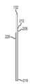
도5는 본 발명의 다른 구체예에 따른 검사 스트립의 평면도를 보여주고;
도6은 도5에서 보여지는 검사 스트립의 A-A 라인에 따른 단면을 보여주고;
도7은 도6에서 보여지는 검사 스트립을 세부부분 B 내에서의 부분적인 단면을 보여주고;
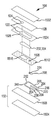
도8은 도5에서 보여지는 검사 스트립의 분해도이고;
도9는 본 발명의 구체예에 따른 도5에 나타난 검사 스트립의 기판의 상면도이고;
도10은 본 발명의 구체예에 따른 도5에 나타난 검사 스트립 기판의 배면도이고;
도11은 본 발명의 구체예에 따른 도5에 나타난 검사 스트립 기판의 입면도이고;
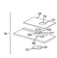
도12는 본 발명의 추가적인 구체예에 따른 검사 스트립의 분해도이고;
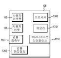
도13은 본 발명의 구체예에 따른 검출장치의 구성요소를 도시하는 블록 다이어그램이고;
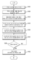
도14는 본 발명의 구체예에 따른 액체 시료의 산화-환원 전위 측정을 위한 프로세스의 일면을 도시하는 순서도이고;
도15는 본 발명의 다른 구체예에 따른 검사 스트립의 분해 전개도이고;
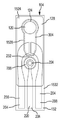
도16은 도 15에 따른 검사 스트립의 상면도이고;
도17은 본 발명의 추가적인 구체예에 따른 검사 스트립의 상면도이고;
도 18은 본 발명의 구체예에 따른 상호연결된 검사 스트립(104)과 검출 전자장치 (1304)의 구성요소를 도시한 것이고;
도19는 본 발명의 다른 구체예에 따라서 액체 시료의 산화-환원 전위를 측정하기 위한 프로세스의 일면을 도시하는 순서도이고; 및
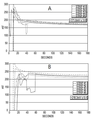
도20A-B는 본 발명의 구체예에 따른 검사 스트립과 검출 장치를 사용하여 노말 및 트라우마 플라즈마의 ORP 값의 예시를 도시하는 그래프이다.1 shows a system for measuring the redox potential of a liquid according to an embodiment of the invention;
2 shows components of a test strip according to an embodiment of the invention;
3 illustrates a test strip overlay component according to an embodiment of the invention;
4 shows the relationship of components in an assembled test strip according to an embodiment of the invention;
5 shows a top view of a test strip according to another embodiment of the present invention;
FIG. 6 shows a cross section along the AA line of the test strip shown in FIG. 5;
FIG. 7 shows a partial cross section in detail B of the test strip shown in FIG. 6;
8 is an exploded view of the test strip shown in FIG. 5;
9 is a top view of the substrate of the test strip shown in FIG. 5 in accordance with an embodiment of the present invention;
10 is a rear view of the test strip substrate shown in FIG. 5 in accordance with an embodiment of the present invention;
11 is an elevational view of the test strip substrate shown in FIG. 5 in accordance with an embodiment of the present invention;
12 is an exploded view of a test strip according to a further embodiment of the present invention;
13 is a block diagram showing components of a detection apparatus according to an embodiment of the present invention;
14 is a flow chart showing one aspect of a process for measuring redox potential of a liquid sample according to an embodiment of the present invention;
15 is an exploded view of a test strip according to another embodiment of the present invention;
16 is a top view of the test strip according to FIG. 15;
17 is a top view of a test strip according to a further embodiment of the present invention;
18 illustrates components of interconnected
19 is a flow chart showing one aspect of a process for measuring the redox potential of a liquid sample in accordance with another embodiment of the present invention; And
20A-B are graphs illustrating examples of ORP values of normal and trauma plasma using test strips and detection devices in accordance with embodiments of the present invention.
본 발명의 구체예는 종전 기술의 이러한 그리고 이외의 문제와 불리한 점을 해결하고, 빠르고 반복적인 임상진단상 테스트에 적합한 산화-환원 전위 (ORP)를 측정하는 시스템 및 방법 제공에 대한 것이다. 상기 시스템은 일반적으로 검사 스트립 및 검출장치를 포함한다. 특히, 본 발명의 구체예는 혈액, 플라스마, 세럼을 포함하는 환자의 체액 혹은 세포외액 및 세포내액 (일례로, 수양액, 유리체, 모유, 수액, 귀지, 내림프액, 외림프액, 위액, 점액, 복막액, 흉수, 샐비어(salvia), 피지, 정액, 땀, 눈물, 질분비물, 구토액, 소변)과 같은 인비트로 소스에서의 ORP를 결정할 수 있다.Embodiments of the present invention are directed to solving these and other problems and disadvantages of the prior art, and to providing systems and methods for measuring redox potentials (ORPs) suitable for rapid and repeatable clinical diagnostic tests. The system generally includes a test strip and a detection device. In particular, embodiments of the present invention are directed to a body fluid or extracellular fluid and intracellular fluid of a patient, including blood, plasma, serum (e.g., sap, vitreous, breast milk, sap, earwax, endolymph, perilymph, gastric juice, mucous, peritoneum) ORP in the source can be determined, such as fluid, pleural effusion, salvia, sebum, semen, sweat, tears, vaginal discharge, nausea, urine).
검사 스트립은 일반적으로 기판, 하나 또는 하나 이상의 검사 리드, 기준 리드, 기준 셀, 브리지를 포함한다. 바람직한 구체예에서, 하나 또는 하나 이상의 검사 리드, 기준 리드, 기준 셀 및 브리지는 오버레이와 기판 사이에 위치한다. 시료 챔버는 일반적으로 브리지의 일부분과 하나 또는 하나 이상의 검사 리드의 일부를 포함한다. 하나 또는 하나 이상의 검사 리드는 작업 전극 및 상대 전극을 포함할 수 있다. 하나의 구체예에서, 샘플챔버를 포함하는 시료부분은 오버레이안에 포함되어 있는 개구부에 의해서 정의된다. 대안으로 또는 이에 더하여, 시료 챔버는 기판 안에 오목부 또는 웰 혹은 중간층에 개구부 또는 웰을 포함한다. 시료 챔버는 일반적으로 혈액 및/또는 혈액 성분과 같은 액체 시료를 포함하도록 구성된다. 액체 시료는 일반적으로 약 1ml 보다 적은 양으로 이루어진다. 바람직하게는, 액체 시료의 양은 혈액 한방울 정도(e.g., 0.05 ml) 혹은 그보다 적다. 본 발명의 구체예에 따르면, 브리지는 브리지와 시료 챔버의 최소한 일부분이라도 기준 셀에 전기적으로 접촉하도록 위치하면서, 액체 시료가 흡수된다.
The test strip generally includes a substrate, one or more test leads, reference leads, reference cells, bridges. In a preferred embodiment, one or more test leads, reference leads, reference cells and bridges are located between the overlay and the substrate. The sample chamber generally includes a portion of the bridge and a portion of one or more test leads. One or more test leads may include a working electrode and a counter electrode. In one embodiment, the sample portion comprising the sample chamber is defined by an opening contained in the overlay. Alternatively or in addition, the sample chamber includes openings or wells in recesses or wells or intermediate layers in the substrate. The sample chamber is generally configured to contain a liquid sample, such as blood and / or blood components. Liquid samples generally consist of less than about 1 ml. Preferably, the amount of liquid sample is less than a drop of blood ( eg , 0.05 ml) or less. According to an embodiment of the invention, the bridge is positioned so that at least a portion of the bridge and the sample chamber are in electrical contact with the reference cell while the liquid sample is absorbed.
기판은 유전체 물질로 구성될 수 있고, 충분히 평평한 표면을 가질 수 있다. 본 발명의 구체예에 따라서, 오버레이는 유전체 물질로 구성될 수 있다. 오버레이는 기판에 결합 혹은 증착될 수 있다.
The substrate may be composed of a dielectric material and may have a sufficiently flat surface. In accordance with an embodiment of the present invention, the overlay may be composed of a dielectric material. The overlay can be bonded or deposited on the substrate.
리드는 충분히 연속적이고 및/또는 균일한 조성을 갖는 전기적 전도성인 물질로 이루어진다. 특히, 리드는 귀금속 혹은 기타 전기적 전도성 물질로 이루어질 수 있다. 일례로, 리드는 프린팅 과정에서 기판에 증착된 전기 전도성 잉크로 이루어 질 수 있다. 하나 또는 하나 이상의 검사 리드는 일반적으로 시료 챔버에서 검출부로 확장되며, 기준 리드는 일반적으로 기준 셀에서 검출부로 확장된다. 검출부는 리드에 연계된 전기적 접촉을 포함하고, 일반적으로 검출장치와 상호연결되어 작동하고, 검출장치와 적어도 하나의 검사 리드 및 기준 리드와 전기적 접촉을 형성하도록 만들어진다.
The lead is made of an electrically conductive material having a sufficiently continuous and / or uniform composition. In particular, the leads may be made of precious metals or other electrically conductive materials. In one example, the lead may be made of an electrically conductive ink deposited on the substrate during the printing process. One or more test leads generally extend from the sample chamber to the detector and the reference leads generally extend from the reference cell to the detector. The detector includes an electrical contact associated with the lead, and is generally adapted to operate in interconnection with the detection device and to form an electrical contact with the detection device and at least one test lead and the reference lead.
기준 셀은 일반적으로 알려진 전압 전위를 제공한다. 기준 셀은 은/염화은 반전지, 구리/황산구리 반전지, 수은/염화제1수은 반전지, 및 표준 수소 반전지 중에 하나로 이루어지나, 이에 제한되는 것은 아니다.
The reference cell generally provides a known voltage potential. The reference cell is composed of, but is not limited to, a silver / silver chloride half cell, a copper / copper sulfate half cell, a mercury / monochloride half cell, and a standard hydrogen half cell.
브리지는 시료 챔버안의 액체 시료와 기준 셀 사이에 전기적 접촉을 형성하기 위해 제공된다. 브리지는 전해질액, 이온 젤, 필터, 또는 종이와 같은 수분 흡수 또는 수분 전달 물질을 포함할 수 있다. 브리지는 일반적으로 시료 챔버와 기준 셀 사이에 위치한다.
A bridge is provided to establish electrical contact between the liquid sample in the sample chamber and the reference cell. The bridge may comprise a moisture absorbing or moisture transfer material such as electrolyte, ionic gel, filter, or paper. The bridge is generally located between the sample chamber and the reference cell.
충분히, 전기적 접촉은 적합한 액체 시료가 시료 챔버에 놓여질 때 리드 사이에 형성이 되고, 브리지는 액체 시료와 기준 셀이 상호 전기적 접촉하게 위치시키도록 작동한다. 일례로, 브리지가 물 전달 물질(water transporting material)을 포함할 때, 액체 시료와 기준 셀 사이에 전기적 접촉을 형성할 만큼 브리지가 충분히 적셔졌을 때, 액체 시료와 기준 셀 사이에 전기적 접촉을 형성하도록 작동한다. 나아가, 전기 회로(electrical circuit)는 액체 시료가 시료 챔버(120)에 위치하고, 둘 또는 그 이상의 리드가 검출장치와 상호연결되어 작동하도록 형성된다.
Sufficiently, electrical contact is established between the leads when a suitable liquid sample is placed in the sample chamber and the bridge operates to position the liquid sample and the reference cell in electrical contact with each other. In one example, when the bridge comprises a water transporting material, when the bridge is sufficiently wetted to form an electrical contact between the liquid sample and the reference cell, the electrical contact between the liquid sample and the reference cell is established. Works. Further, the electrical circuit is formed such that a liquid sample is located in the
검출장치는 일반적으로 볼타미터(voltmeter), 갈바노스탯(galvanostat), 포텐시오스탯(potentiostat) 혹은 작업 전극, 상대 전극, 및/또는 검사 스트립의 기준 리드를 전기적으로 상호연결하여 액체 시료의 ORP를 포함하거나 이를 대표하는 전위차를 읽을 수 있는 기타 장치로 이루어진다. 적합한 검출장치의 예로는 아날로그 볼타미터, 디지털 볼타미터, 아날로그 영위평형 볼타미터(analog null-balance voltmeters), 갈바노스탯, 및 포텐시오스탯이 포함되나 이에 한정되는 것은 아니다. 일부 구체예에서, 검출장치는 검출장치의 하나 또는 하나 이상의 선택적인 측면을 제어하도록 메모리를 포함하고/포함하거나 연계되는 프로세서를 갖는다. 상기 프로세서는 메모리에 저장된 지시사항을 실행할 수 있고, 측정된 전압에 따라 프로세스를 실행할 수 있고, 및/또는 시간 간격에 따라서 프로세스를 실행할 수 있으나, 이에 제한되는 것은 아니다. 검출장치는 더 나아가 사용자 인풋과 사용자 아웃풋 중에 하나 혹은 둘 모두를 포함할 수 있다. 사용자 아웃풋의 예로는, 하나 또는 하나 이상의 산화-환원 전위 값을 디스플레이하는 디지털 아웃풋, 표시램프, 기계에서 생산되는 언어안내, 및 반복적인 가청 톤이 있으나, 이에 제한되는 것은 아니다. 사용자 인풋의 예로는, 버튼, 스위치, 키패드, 키보드, 및/또는 사용자로부터 인풋을 수신하는 터치스크린인터페이스(touch screen interface) 가 있으나 이에 제한되는 것은 아니다.
The detection device typically electrically interconnects the reference lead of a voltmeter, galvanostat, potentiostat or working electrode, counter electrode, and / or test strip to remove the ORP of the liquid sample. Or other device capable of reading the potential difference which includes or is representative of it. Examples of suitable detection devices include, but are not limited to, analog voltammeters, digital voltammeters, analog null-balance voltmeters, galvanostats, and potentiostats. In some embodiments, the detection device has a processor that includes and / or is associated with a memory to control one or more optional aspects of the detection device. The processor may execute instructions stored in a memory, execute a process according to a measured voltage, and / or execute a process at a time interval, but is not limited thereto. The detection device may further comprise one or both of a user input and a user output. Examples of user outputs include, but are not limited to, digital outputs displaying one or more redox-reduction potential values, indicator lamps, language guidance produced by the machine, and repetitive audible tones. Examples of user inputs include, but are not limited to, buttons, switches, keypads, keyboards, and / or touch screen interfaces that receive input from a user.
본 발명의 또 다른 측면은 시료의 ORP를 결정하기 위한 시스템을 사용하는 방법이다. 상기 방법은 일반적으로 다음 단계를 포함한다: a) 액체 시료를 획득하는 단계; b)검사 스트립의 시료 챔버안에 액체 시료를 위치시키는 단계; c) 브리지를 사용하여 상기 시료 챔버와 기준 셀 사이에 전기적 접촉을 충분히 형성하는 단계; d) 검사 스트립의 기준 전극과 테스트 전극을 검출장치에 상호연결하는 단계; e) 정해진 시간이 지난 후 ORP를 결정하는 단계. 하나의 구성에서, 단계 b)는 더 나아가 전혈 액체 시료에서 플라스마 성분을 분리하는 것을 포함하며, 여기서 플라스마는 시료 챔버에 모아진다. 또 다른 구성에서, 단계 d)는 더 나아가 상대 전극을 검출장치에 상호연결하고, 작업 전극과 상대 전극 사이에 전류를 흐르게 하고, 기준 전극와 작업 전극 사이의 전압을 측정하는 것을 포함한다.
Another aspect of the invention is a method of using a system to determine the ORP of a sample. The method generally includes the following steps: a) obtaining a liquid sample; b) placing the liquid sample in the sample chamber of the test strip; c) forming a sufficient electrical contact between the sample chamber and the reference cell using a bridge; d) interconnecting the reference and test electrodes of the test strip to the detection device; e) determining the ORP after a set time. In one configuration, step b) further comprises separating the plasma component from the whole blood liquid sample, where the plasma is collected in the sample chamber. In another configuration, step d) further comprises interconnecting the counter electrode to the detection device, allowing a current to flow between the working electrode and the counter electrode, and measuring the voltage between the reference electrode and the working electrode.
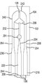
도1 은 본 발명의 구체예에 따른 액체의 산화-환원 전위를 측정하기 위한 시스템(100)을 도시한다. 시스템(100)은 검사 스트립(104) 그리고 검출장치(108)을 일반적으로 포함한다. 또한 시스템(100)의 일부로 보여지는 것은 액체 시료(116)을 공급하기 위한 액체 시료원(112)이다. 1 shows a
검사 스트립(104)는 일반적으로 시료 챔버(120)을 포함한다. 시료 챔버(120)은 검사 스트립 오버레이(128)안에 형성되는 검사 스트립 오버레이 개구부(124)에 대응할 수 있다. 검사 스트립 오버레이(128)은 검사 스트립 기판 (132)에 상호연결될 수 있다. 다수의 전기적 접촉부 (136)가 검출부(140)안에서 제공될 수 있다. 전기적 접촉부(136)은 다양한 리드 및 검사 스트립(104)의 다른 구성요소와 연계될 수 있으며, 본 발명의 다른 부분에서 보다 자세히 설명될 것이다.
검출장치(108)은 복수의 검출장치 접촉부 (144)를 포함할 수 있다. 검출장치 접촉부 (144)는 일반적으로 검출장치(108)와 검사 스트립(104)의 전기적 접촉부(136)사이에 전기적 연결을 형성하도록 구성된다. 예시된 시스템(100)에서 보여지는 것처럼, 검출장치 접촉부(144)는 검사 스트립(104)이 검출장치(108)과 연결될 때, 검사 스트립(104)의 검출부(140)을 수용하는 검출 개구부(148)와 연결될 수 있고, 이를 통하여 전기적 신호가 검출장치(108)에 의하여 검사 스트립(104)의 전기적 접촉부(136)으로부터 읽힐 수 있다. 또 다른 방법으로, 검출장치 접촉부 (144)은 검사 스트립(104)의 전기적 접촉부(136)에 접촉하도록 할 수 있는 두 개 혹은 그 이상의 유연성 와이어 또는 리드로 이루어질 수 있다.
The
일반적으로, 검출장치(108)는 전압계(voltmeter)를 포함한다. 특히, 검출장치(108)은 두 개의 검출 접촉부 사이의 전압을 측정하도록 작동한다. 따라서, 검출장치 접촉부(144)는 검사 스트립(104)의 어떤 두 개의 전기적 접촉부(136)사이의 전위 혹은 전압을 측정하도록 작동한다. 추가적인 구체예에 따라서, 검출장치(108)은 정전류 측정(galvanostatic measurement)을 수행할 수 있는데, 이는 본 발명의 다른 부분에서 보다 상세하게 설명된다. 또 다른 방법으로, 본 발명의 구체예에 따라서, 검사 스트립(104)는 세 개의 전기적 접촉부(136)을 제공하는 대신에 두 개의 전기적 접촉부(136)를 포함할 수 있다. 이와 유사하게, 검출장치(108)은 두 개의 검출장치 접촉부(144)를 포함한다. 나아가, 검출장치 접촉부(144) 및/또는 검출 개구부(148)의 특정한 배열은 다른 검사 스트립(104)의 전기적 접촉부(136)과 검출부(140)의 다른 배열을 수용하기 위해서 변형될 수 있다.
In general, the
검출장치(108)은 추가적으로 사용자 아웃풋(152)를 포함할 수 있다. 일례로, 사용자 아웃풋(152)는 의사에게 액체 시료(116)에 관련된 산화-환원 전위를 제공하기 위한 시각적 디스플레이를 포함할 수 있다. 대안으로 또는 이에 더하여, 사용자 아웃풋(152)는 스피커 혹은 기타 음향 출력 원을 포함할 수 있다. 또한, 사용자 인풋(156)이 의사가 검출장치(108)의 작동을 제어하도록 제공될 수 있다.
The
본 발명의 구체예에 따라서, 액체 시료(116)는 혈액 혹은 혈액 성분을 포함할 수 있다. 일례로, 액체 시료(116)은 인간의 전혈 혹은 플라스마를 포함할 수 있다. 액체 시료원 (112)는 검사 스트립(104)의 시료 챔버(120)에 적합한 시료 액(116)의 용량을 위치하기에 적합한 어떠한 용기 혹은 장치를 포함할 수 있다. 따라서, 시료 액 장치(112)의 일례로 주사기, 랜싯(lancet), 피펫, 바이알 또는 다른 용기 또는 장치를 포함한다.
According to an embodiment of the invention, the
도2는 검사 스트립 오버레이(128)이 제거된 검사 스트립(104)의 구성요소를 나타낸다. 일반적으로, 기판(132)는 그 표면에 검사 스트립 검출 접촉부 (136)에서 마감되는 다수의 전기 전도성 리드 (204)을 포함하고/포함하거나 형성한다. 기판(132) 자체가 유전체 물질로 이루어 질 수 있다. 나아가, 기판(132)는 검사 스트립(104)의 다수의 구성요소들이 상호연결되거나 혹은 형성된 충분히 평면인 표면으로 이루어질 수 있다. 추가적인 구체예에 따르면, 검사 스트립(104) 기판(132)는 검사 스트립(104)의 시료 챔버(120)에 상응하는 위치에 오목부 혹은 웰(206)으로 이루어질 수 있다.
2 shows the components of the
리드(204)중에 적어도 하나는 제1 검사 리드이거나 혹은 작업 전극(208)인데, 이는 검사 스트립(104)의 시료 챔버(120)에 상응하거나 혹은 안에 있는 제1영역(212)와 작업 전극(208)의 검출 접촉부(136)에 상응하는 제2영역(216) 사이에 이어진다. 본 발명의 구체예에 따라서, 작업 전극(208)의 적어도 제1영역(212)는 충분히 연속적이고/연속적이거나 균일한 조성을 갖는 전기 전도성 물질로 이루어진다. 여기서 사용되는 것처럼, 충분히 연속적이고/연속적이거나 균일한 조성은 작업전극(208)을 구성하는 물질이 작업전극(208)의 단면에서의 어느 지점에서처럼 작업 전극(208)의 일부의 단면의 모든 지점에서 동일한 화학적 조성 및/또는 분자구조를 갖는다는 것으로 이해되어야 한다. 특히, 작업 전극(208)의 전기 전도성 물질은 시료액(116)에 대해서 화학적으로 반응하지 않는 것으로 선택된 물질에 의해서 코팅되지 않거나 혹은 충분히 코팅되지 않는 것이 바람직하다.
At least one of the
청구항에 반드시 제한을 제공하지는 않는 일례로서, 작업 전극(208)은 프린팅 과정에서 기판에 증착된 전기 전도성 잉크를 포함할 수 있다. 추가적인 예시적 구체예에 따르면, 작업 전극 (208)은 기판 (132)에 적층되거나 혹은 다른 방식으로 연결되는 전기 전도성 층을 포함할 수 있다.
As one example that does not necessarily provide a limitation in the claims, the working
본 발명의 구체예에 따른 검사 스트립(104)는 기준 리드 혹은 전극 (220)을 포함하는 리드(204)를 추가적으로 포함한다. 기준 리드(220)은 일반적으로 기준 셀(224) 및 기준 리드(228)의 검출부 사이에서 확장한다. 본 발명의 예시적인 구체예에 따르면, 기준 리드(220)은 작업 전극과 같거나 혹은 유사한 프로세스를 활용하여 형성될 수 있다.
기준 셀(224)는 알려진 전압 전위를 제공하도록 선택된다. 일례로, 기준 셀(224)은 은/염화은, 구리/황산구리, 수은/염화제1수은, 표준 수소전극 또는 다른 전기화학적 기준 반전지로 이루어진다.
브리지(232)는 기준 셀(224) 및 시료 챔버(120) 사이에서 연장된다. 본 발명의 구체예에 따르면, 브리지(232)는 필터를 포함할 수 있다. 예를 들어, 브리지(232)는 필터지로부터 형성될 수 있다. 본 발명의 개시내용을 고려하여 당업자가 이해할 수 있는 것처럼, 액체 시료(116)가 시료 챔버(120)에 위치할 때, 필터지는 적셔지면서 시료 챔버(120)안의 액체 시료(116) 그리고 기준 셀(224) 사이에 전기적으로 전도성인 브리지(232)를 형성한다.
또한, 본 발명의 구체예에 따른 검사 스트립(104)는 제2 검사 리드 혹은 상대 전극 (236)을 포함할 수 있다. 상대 전극(236)은 일반적으로 작업 전극 (208)을 반영한다. 따라서, 상대 전극(236)은 충분히 연속적이거나 균일한 전기적 전도성 물질로 형성이 되는데, 이는 시료 챔버(120)과 일치하는 제1 영역(240)에서부터, 상대 전극(236)의 검출 부분(136)에 상응하는 제2영역(244)까지 연장된다.
In addition, the
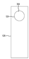
다음으로 도3은 본 발명의 구체예에 따른 검사 스트립(104) 오버레이(128)의 평면도를 도시한다. 검사 스트립 (104) 오버레이 (128)는 조립된 검사 스트립 (104)의 시료 챔버(120)에 상응하는 검사 스트립 개구부 (124)를 포함한다. 본 발명의 구체예에 따르면, 검사 스트립 오버레이(128)는 기판(132)에 접착 또는 적층된 평평한 유전체 물질을 포함할 수 있으며, 이를 통하여 리드(204), 기준 셀(224) 및 브리지(232)는 기판(132) 및 오버레이(128)의 사이에 수용된다. 본 발명의 추가적인 구체예에 따르면, 필터 혹은 필터 성분(304)가 검사 스트립 개구부(124)에 걸쳐서 연장될 수 있다. 필터(304)는 전혈로 이루어진 액체 시료(116) 안의 플라스마가 검사 스트립 개구부를 거쳐 시료 챔버(120)까지 통하도록 기능하는 막을 포함할 수 있다. 본 발명의 최소한 일부 구체예에 따르면, 필터(304)는 필터지를 포함할 수 있다. 나아가, 본 발명의 다른 구체예에 따르면, 필터(304)는 최소한 필터(304)가 적셔졌을 때 시료 챔버(120)과 기준 셀(224)사이에 브리지(232)를 형성하도록 연장될 수 있다.
3 shows a top view of
도4는 본 발명의 구체예에 따른 조립된 검사 스트립(104)의 평면도를 나타낸다. 나아가, 조립된 검사 스트립(104)안에 있는 검사 스트립 오버레이(128) 아래에 있는 검사 스트립(104)의 다양한 특징이 상호 위치를 나타내기 위해서 점선으로 보여진다. 본 발명에 개시된 내용을 통하여 당업자가 이해할 수 있는 바와 같이, 시료 챔버(120)안에 적합한 액체 시료(116)가 부재하는 경우, 다양한 리드(204)는 상호 전기적으로 접촉되지 않는다. 특히, 적합한 액체 시료(116)이 시료 챔버(120)안에 위치하고, 브리지(232)가 액체 시료(116)을 통해 기준 리드(220)을 작업 전극(208) 및/또는 상대 전극(236)에 전기적으로 접촉에 위치시킬 수 있을 만큼 충분히 적셔질 때까지 리드(204)는 상호 전기적으로 접촉되지 않는다. 나아가, 어떤 두 개의 리드(204)를 포함하는 전기 회로는 검사 스트립이 검출장치(108)에 작동적으로 상호연결되기 전까지 완성되지 않는다.
4 shows a top view of an assembled
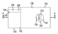
도5는 본 발명의 구체예에 따른 검사 스트립(104)의 평면도를 나타낸다. 검사 스트립(104)는 일반적으로 기판(132)의 일부를 최소한 덮는 검사 스트립 오버레이(128)이 있는 기판(132)를 포함한다. 검사 스트립 오버레이(128)은 시료 챔버(120)에 상응하는 공간에 검사 스트립 개구부(124)를 포함한다. 보여지는 것처럼, 검사 리드(208)의 제1 영역 (212)는 시료 챔버(120)으로 연장된다. 검출 접촉부(136)에 상응하는 검사 리드(208)의 제2영역 (216)은 검사 스트립(104)의 검출부 (140)에 상응하는 기판(132)의 일부분 위에 있는데, 이 부분은 검사 스트립 오버레이(128)가 덮지 않는다.
5 shows a top view of
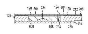
도6은 도5에서 보여지는 검사 스트립을 A-A 라인에 따라 나누어진 단면을 보여준다. 상기 구체예에서, 기준 셀(224)는 젤 볼륨(gel volume)(604)안에 포함된다. 젤 볼륨(604)는 기판(132)에 형성된 개구부(608)로 정의된다. 젤 볼륨(604)의 하단은 기준 셀 캐리어 플레이트(carrier plate)(612)로 구획된다. 젤 볼륨(604)의 상단은 부분적으로 검사 스트립 오버레이(128)로 폐쇄된다.
FIG. 6 shows a cross section along the AA line of the test strip shown in FIG. 5. In this embodiment, the
도7은 도6에서 보여지는 검사 스트립(104)에 대한 세부영역 B 내에서의 부분적인 단면을 보여준다. 도7에서 보여지는 것처럼, 기판(132)안에 형성된 개구부(608)에 있는 노치(notch)(704)는 적어도 부분적으로는 검사 스트립 오버레이(128)에 형성된 검사 스트립 개구부(124)와 겹쳐진다. 따라서, 젤 볼륨(604)은 시료 챔버(120)과 소통된다. 결과적으로, 시료 챔버(120)안에 위치한 액체 시료(116)의 적어도 일부는 젤 볼륨(604)에 진입할 수 있으며, 따라서 액체 시료(116)은 젤(708)과 접촉하게 된다. 특히, 젤(708)은 적어도 부분적으로는 젤 볼륨(604)를 채운다. 본 발명의 구체예에 따라서, 젤(708)은 이온성 액체 또는 전해질액을 포함할 수 있다. 따라서, 젤(708)은 액체 시료가 기준 셀(224)와 전기적 접촉에 놓이도록 기능한다.
FIG. 7 shows a partial cross section in detail area B for the
다시 도5에서, 기판(132)안에 형성된 개구부(608)안의 노치(704)와 검사 스트립 오버레이(128)안에 형성된 검사 스트립 개구부(124)는 시료 챔버(120)를 젤 볼륨(604)와 소통하도록 위치시키는데 공동으로 작용한다.
5 again, the
또한, 도7에서 시료 챔버(120)을 덮는 필터(304)를 볼 수 있다. 필터(304)는 시료 챔버(120)안이나 혹은 위의 전혈에서 혈액 플라스마를 분리시켜, 혈액 플라스마가 검사 리드(208)의 제1영역(212) 그리고 젤 볼륨(604)안의 젤(708)과 접촉할 수 있게 하는 막일 수 있다. 예시적인 구체예에서, 기준 리드(220)은 기판(132)에서 검사 리드(208)가 위치하는 측면의 반대 측면에 있다. 기준 리드(220)은 전기적 전도성의 캐리어 플레이트(612)을 통한 전기적 접촉을 통해서 기준 셀(224)에 전기적으로 접촉하도록 위치한다.
Also shown in FIG. 7 is a
도8은 도5에 나타난 검사 스트립(104)의 분해도이다. 상기 분해도에서, 작업 전극(208)이 기판(132)에 형성되어 제1영역(212)에서 제2영역(216)으로 연장되는 것이 나타난다. 또한, 상기 구체예에서 기준 셀(224)는 전기적 전도성 있는 기준 셀 캐리어 플레이트(612)의 중앙에 위치한다.
8 is an exploded view of the
도9는 도5에 나타난 검사 스트립(104)의 기판(132)의 상면도이다. 도 10은 검사 스트립 기판(132)의 배면도이다. 도11은 검사 스트립 기판(132)의 입면도이다. 도9에 나타난 것처럼, 기판(132)의 개구부(608)은 원형일 수 있고, 그 주변부를 따라서 노치(704)가 형성이 된다. 도10은 작업 리드(208)이 위치한 기판(132) 반대편에 형성된 기준 리드(220)를 보여준다. 특히, 기준 리드(220)는 젤 볼륨(604)의 외부 공간을 둘러싸는 원형 부분을 포함한다. 나아가, 검사 리드(208)과 기준 리드(220)은 기판(132)의 반대편에 형성이 될 수 있다 (도11 참조).
9 is a top view of the
다음으로 도12는 본 발명의 추가적인 구체예에 따른 검사 스트립(104)의 분해도이다. 특히, 상기 구체예는 이온성 젤 또는 다른 전해질을 포함하는 캡슐(1204)을 포함한다. 흡수부재(Wicking member)(1208)는 캡슐(1204)의 아래에 위치한다. 흡수부재(1208)는 시료 챔버(120)와 소통하는 탭(1212)를 포함한다. 사용시에, 캡슐(1204)는 부서지고, 흡수부재(1208)를 적시면서, 이로서 시료 챔버(120)안에서 시료액(116)과 기준 셀(224)사이의 염 브리지를 형성한다. 조립된 검사 스트립(104)에서 젤 캡슐(1204)와 흡수부재(1208)는 검사 스트립 오버레이(128)과 기준 셀 캐리어 플레이트(612)사이에서 기판(132)에 형성된 개구부(608)안에 담겨진다.
12 is an exploded view of
도13은 본 발명의 구체예에 따른 검출장치(108)의 구성요소들을 도시하는 블록 다이어그램이다. 일반적으로, 검출장치(108)은 다수의 검출장치 접촉부(144)를 포함한다. 검출장치 접촉부(144)은 수신 구조와 연계될 수 있는데, 도1에 나타난 개구부(148)과 같은 것으로, 적어도 두 개 이상의 검출장치 접촉부(144)과 검사 스트립(104)의 적어도 두 개이상의 전기적 접촉부(136) 사이를 전기적으로 상호연결 가능하도록 하기 위해, 검사 스트립(104)와 검출장치(108)을 기계적으로 상호연결한다. 대안으로 또는 이에 더하여, 검출장치 접촉부(144)는 검사 스트립(104)의 전기적 접촉부(136)과 선택적으로 연결될 수 있게 위치한 전도성 리드 혹은 프로브를 포함할 수 있다.
Fig. 13 is a block diagram showing the components of the detecting
또한, 검출장치(108)은 전압계 혹은 검출 전자장치부(1304)를 포함하거나 구성될 수 있다. 당업자가 이해할 수 있는 것처럼, 검출 전자장치(1304)는 다양한 방법으로 시행될 수 있다. 일례로, 검출 전자장치(1304)는 갈바노스탯을 포함할 수 있다. 또 다른 일례로, 엔드포인트 전자장치(endpoint electronics)는 포텐시오스탯을 포함할 수 있다. 추가적인 구체예로, 검출 전자장치(1304)는 통합 변환기(integrating converter)를 포함하는 디지털 전압계를 포함할 수 있다. 추가적인 구체예에 따르면, 검출 전자장치(1304)는 아날로그 전압계나 디지털 혹은 아날로그 영위평형(null balance) 전압계를 포함할 수 있다.
In addition, the
메모리(1312)를 포함하고/포함하거나 연계되는 프로세서(1308)는 검출장치(108) 작동의 다양한 측면을 제어하도록 제공될 수 있다. 일례로 메모리(1312)에 저장된 지시사항을 실행하는 프로세서(1308)은 검출 전자장치(1304)에 의해 작업 전극(208)(혹은 선택적으로 상대 전극(236))과 기준 전극(220)사이의 전압을 시간을 두고 모니터하는 프로세스를 실행할 수 있다. 나아가, 상기 전압은 검출 전자장치(1304)가 적어도 상대 전극(236)과 작업 전극(208)사이에 전류를 흐르게 하는 동안 모니터될 수 있다. 프로세서(1308)은 나아가 검출 전자장치(1304)에서 확인한 전압에서 시료 챔버(120)에 있는 액체 시료(116)의 산화-환원 전위를 나타내는 검출을 산출하고 디스플레이하도록 작동할 수 있다.
시료 챔버(120)안의 액체 시료(116)의 결정된 산화-환원 전위에 대한 정보를 사용자에게 제공하기 위해서, 사용자 아웃풋(152)가 제공된다. 사용자 아웃풋(152)은 예시적인 구체예에서 산화-환원 전위 값을 디스플레이하는 디지털 아웃풋으로 이루어질 수 있다. 대안으로 또는 이에 더하여, 사용자 아웃풋(152)는 표시램프, 아날로그 아웃풋, 또는 기타 시각적 분별이 가능한 아웃풋을 포함할 수 있다. 또한 추가적인 구체예에 따르면, 사용자 아웃풋(152)는 선택된 톤 또는 톤의 반복 또는 기계적으로 생산된 음성과 같은 가청 아웃풋을 포함할 수 있다.
In order to provide the user with information about the determined redox potential of the
사용자 인풋(156)은 사용자로부터 제어 정보를 수신하기 위해 포함될 수 있다. 일례로, 사용자 인풋(156)은 검출장치(108)의 전원 온/오프 및 검출 장치(108)의 적합한 작동에 관련된 진단을 수행하고, 다양한 작동 파라미터, 혹은 다른 사용자 인풋에 대한 입력을 수신한다. 일례로, 사용자 인풋(156)은 버튼, 스위치, 키패트, 및/또는 시각적 디스플레이와 통합된 터치스크린 인터페이스를 포함할 수 있고 이러한 것들은 사용자 아웃풋(152)에 포함될 수 있다.
검출장치(108)은 추가적으로 커뮤니케이션 인터페이스(communications interface) (1316)를 포함할 수 있다. 커뮤니케이션 인터페이스(1316)가 제공될 경우 검출장치(108)와 다른 시스템들 혹은 장치들 사이의 상호연결을 지원할 수 있다. 일례로, 커뮤니케이션 인터페이스(1316)는 유선 혹은 무선 이더넷 접속, USB포트, 혹은IEEE 1394 포트로 이루어져 검출장치(108)을 개인용 컴퓨터 혹은 컴퓨터 네트워크에 상호연결한다.
The
또한, 다른 장치들에 상호 연결이 되거나 혹은 되지 않는 전문적인 독립적 장치로 구성된 예시적인 검출장치 (108)가 묘사되었지만, 본 발명의 구체예는 그것만으로 제한적이지 않다. 일례로, 본 발명의 구체예에 따른 검출장치(108)은 표준 전압계로서 실행될 수 있다. 다른 구체예에 따르면, 검출장치(108)은 전기적 테스트 혹은 진단 시스템을 포함할 수 있는데, 예를 들어 단독으로 또는 개인 컴퓨터와 연결하여 작동되는 사용자가 설정 가능한 포텐시오스탯 및/또는 갈바노스탯(user configurable potentiostat and/or galvanostat)과 같은 것이 있다. 상기 다른 구체예에 따르면, 검출장치(108)은 적합한 프로그래밍을 실행하고, 작업 전극(208)과 검사 스트립(104)의 기준 전극(220) 사이의 전압을 감지할 수 있는 인터페이스를 제공하는 개인용 컴퓨터처럼 실행될 수 있다.
In addition, although an
도14는 본 발명의 구체예에 따른 액체 시료(116)의 산화-환원 전위를 결정하는 방법의 측면을 보여준다. 맨 처음에 1404단계에서 액체 시료(116)은 시험대상 혹은 환자로부터 획득이 된다. 본 발명의 구체예에 따라서, 액체 시료(116)은 플라스마와 같은 전혈 혹은 혈액 성분으로 이루어 진다. 당업자에 의해서 이해될 수 있는 바와 같이, 전혈 또는 혈액 성분으로 이루어지는 액체 시료(116)은 시험대상으로부터 일례로 주사기와 바늘 또는 랜싯을 사용하여 획득될 수 있다. 추가적인 구체예에서, 액체 시료는 시험대상 생물로부터의 어떤 종류의 액체라도 포함할 수 있다. 나아가, 시험대상은 인간 혹은 그 밖의 모든 포유류나 동물을 포함할 수 있다.
Figure 14 shows an aspect of a method of determining the redox potential of a
1408단계에서, 액체 시료(116)은 검사 스트립(104)의 시료 챔버(120)에 위치한다. 액체 시료(116)이 플라스마로 이루어지는 경우, 플라스마는 별도의 프로세스에서 전혈로부터 분리될 수 있다. 또 다른 방법으로, 시료액(116)이 전혈로 이루어지는 경우, 시료 챔버(120)위의 필터(304)는 플라스마 성분으로부터 전혈의 다른 성분들을 필터링하도록 작동할 수 있다. 이때 액체 시료(116)의 플라스마 성분은 시료 챔버(120) 혹은 시료 챔버(120)의 일부분에 모이게 된다.
In
1412단계에서, 전기적 전도성의 브리지(232)는 기준 셀(224)와 시료 챔버(120)사이에 형성된다. 본 발명에 따른 적어도 일부의 구체예에 따르면, 필터지의 스트립을 포함하는 필터(304)의 적어도 일부를 사용하여 형성된 브리지(232)를 적시면서, 이에 따라 시료 챔버(120)와 기준 셀(224) 사이에 염 브리지를 형성하면서 가능해진다. 또 다른 구체예에 따라서, 이는 액체 시료(116)이 필터(304) 및/또는 브리지(232)에 직접 혹은 연결이 된 기준 셀(224)에 접촉하는 전해질 젤과 접촉하도록 위치시킨다. 1416단계에서, 검사 리드(208)과 기준 리드(220)은 검출장치(108)의 전기적 접촉부(144)에 상호연결된다. 1420단계에서, 작업 전극 혹은 검사 리드(208) 그리고 기준 전극(220) 사이의 전압 혹은 전기적 전위가 결정된다. 선택된 간격이 경과한 후, 작업 전극 혹은 검사 리드(208) 그리고 기준 전극(220) 사이의 전압을 이어서 읽게 된다(1424 단계). 1428단계에서, 두개의 읽혀진 값 사이의 차이 비율이 시스템이 평형단계에 도달하였고 따라서 신뢰할 만한 값이 획득이 되었는지에 대한 결정이 내려진다. 시스템이 평형에 도달하지 않았다고 결정이 되면, 시스템은 1424단계로 돌아가고, 나아가 작업 전극(208)과 기준 셀 전극(220)사이의 전압을 이어서 읽게 된다. 1428단계에서 시스템이 안정화된 것으로 결정이 되면, 시료 챔버(120)안의 액체 시료(116)의 산화-환원전위 측정치는 출력 될 수 있다(1432단계). 일례로, 액체 시료(116)의 산화-환원전위에 대한 표시는 사용자 아웃풋(152)을 통해서 출력되거나 및/또는 커뮤니케이션 인터페이스(1316)을 통해서 또 다른 기기로 출력될 수 있다.
In
또 다른 구체예에 따라서, 샘플(116)의 산화-환원 전위를 결정하기 위해 커브피팅(curve fitting) 공정이 실행될 수 있다. 일례로, 작업 전극 (208)과 기준 셀 전극(220) 사이의 전압은 적어도 세 번의 다른 시간에 맞춰 측정될 수 있고, 이렇게 획득된 데이터는 산화-환원 전위 값에 도달하도록 커브피팅 알고리즘에 적용될 수 있다. 커브피팅 알고리즘은 확산방정식, 다항 커브피팅 알고리즘(polynomial curve fitting algorithm), 또는 다른 커브피팅 알고리즘을 포함할 수 있다.
According to another embodiment, a curve fitting process may be performed to determine the oxidation-reduction potential of the
본 발명의 구체예에 따라서, 검사 스트립(104)는 리드(204) 그리고 다른 구성요소를 기계적으로 지지할 수 있는 어떠한 유전체 물질을 포함하는 기판(132)을 사용하여 형성될 수 있다. 따라서, 기판(132)는 플라스틱, 세라믹, 유리, 혹은 기타 다른 물질을 포함할 수 있다. 나아가, 기판(132)는 물질의 평평한 면을 포함할 수 있다. 리드(204)는 다양한 방법을 통해서 형성될 수 있다. 일례로, 리드(204)는 기판(132) 상에 전도성 잉크의 형태로 증착될 수 있다. 적합한 전도성 잉크의 예로는 그라파이트 잉크 및 귀금속(예를 들어, 금, 백금 또는 이리듐)이 있다. 또한, 리드(204)는 다른 다양한 증착 및/또는 에칭 프로세스로 형성될 수 있다. 나아가, 기준 셀(224) 그리고 브리지(232)는 기판(132)에 적합한 물질을 위치시킴에 의하여 적용될 수 있다.
In accordance with an embodiment of the invention, the
검사 스트립 오버레이(128)은 기판(132)와 동일 또는 유사한 물질을 포함할 수 있다. 나아가, 검사 스트립 오버레이 (128)는 시료 챔버(120)에 상응하는 검사 스트립 개구부(124)를 포함한다. 검사 스트립 오버레이(128)은 기판(132)에 접착될 수 있고, 그래서 리드(204), 기준 셀(224), 브리지(232)와 같은 일부 혹은 전체의 다른 구성요소가 적어도 부분적으로 기판(132)의 충분히 평평한 상부 표면과 검사 스트립 오버레이(128)의 충분히 평평한 하단 표면 사이에 위치할 수 있다.
The
기준 셀(224)은 어떠한 알려진 기준 전압을 제공할 수 있는 전극 혹은 화학적 반전지를 포함할 수 있다. 따라서, 기준 셀(224)는 표준 수소 전극, 은/염화은 전극, 칼로멜(calomel) 전극, 황산제1수은(mercurous sulfate) 전극, 산화제2수은 전극, 또는 구리/황산구리 전극을 포함할 수 있다. 젤(708)을 포함하는 검사 스트립(104)의 구체예에서, 상기 젤(708)은 어떠한 이온성 액체, 전해질 용액 또는 이온성 젤을 포함할 수 있다. 적합한 젤(708)의 예는 양이온성 고분자, 이온성 액체, 및 젤화된 전해질을 포함한다.
본 발명에 따른 추가적인 구체예는 도 15 및 도 16에 의하여 설명된다. 도 15는 본 발명의 구체예에 따른 검사 스트립(104)의 분해도를 나타낸다. 도 16은 상부에서 본 도 15의 검사 스트립(104)을 나타낸다. 검사 스트립(104)은 기판(132)을 포함한다. 더욱 구체적으로, 이 구체예에서 상기 기판(132)은 구조적 지지층(1504) 및 장벽층(1508)을 포함한다. 장벽층(1508)은 액체가 통과할 수 없는 층을 포함할 수 있다. 예를 들어, 장벽층(1508)은 연신된 폴리에스터 필름, 예를 들어, MylarTM 같은 이축연신된 폴리에틸렌 테레프탈레이트를 포함할 수 있으나 이에 한정되는 것은 아니다. 구조적 지지층(1504)은 이후 층들에 대한 기계적 지지를 제공할 수 있을 정도로 충분히 단단한 섬유 또는 고분자층을 포함할 수 있고, 예를 들어 폴리에스터 물질일 수 있으나 이에 한정되는 것은 아니다.
Further embodiments according to the invention are illustrated by FIGS. 15 and 16. 15 shows an exploded view of
전기적으로 전도성인 리드(204)는 장벽층(1508)에 의하여 지지된다. 예를 들어, 전도성 리드(204)는 스퍼터링, 프린팅, 에칭, 스텐실링, 또는 플레이팅 공정에 의하여 장벽층(1508)의 면에 증착될 수 있으나 이에 한정되는 것은 아니다. 전기적으로 전도성인 리드(204)는 어떠한 전기 전도성 물질로부터도 형성될 수 있다. 적절한 전기 전도성 물징의 예는 백금, 금, 도핑된 탄소를 포함한다. 전도성 리드(204)는 다양한 패턴으로 형성될 수 있다. 일반적으로, 전도성 리드(204)는 작업전극(208), 기준전극(220), 및 상대전극(236)을 포함한다.
The electrically
기준 셀(224)은 장벽층(1508)에 증착된 젤(708) 내에 위치할 수 있다. 더욱이, 젤(708)의 적어도 일부는 기준 리드 또는 전극(22)의 일부 상에 위치하거나 또는 접촉된다. 유전층(1512)은 장벽층(1508)의 일부 위에 위치하거나 형성될 수 있다. 예를 들어, 유전층(1512)은 다양한 전기적으로 전도성인 리드(204)의 부분들을 덮을 수 있고, 반면, 전기적으로 전도성인 리드(204)의 검출부(14)에 해당하는 전기적으로 전도성인 리드(204)의 부분은 덮이지 않는다. 나아가, 유전층(1512)은 작업전극(208)의 제1부분(212) 및 상대전극(236)의 제1부분(240)가 덮이지 않고, 시료 챔버(120)에 대응하는 부분에 노출된 제1 개구부(1516)을 포함할 수 있다. 유전층(1512)은 제2 개구부(1520)를 추가적으로 포함할 수 있다. 제2 개구부(1520)는 기준 셀(224) 및/또는 젤(708)과 대응될 수 있다. 예를 들어, 유전층(1512)은 유전필름 또는 증착된(예를 들어, 프린팅된) 유전물질로부터 형성될 수 있다.
필터(304)는 유전층(1512)의 제1 개구부(1516) 및 제2개구부(1520)의 적어도 일부분을 포함하는 부분으로부터 연장되도록 제공된다. 여기서 설명된 다른 구체예들과 마찬가지로, 필터(304)는 습윤화되었을 때, 직접적으로 또는 젤(708)을 통하여 시료 챔버(120) 내의 시료(116)의 일부와 기준 셀(224)을 전기적으로 연결하는 브리지(232)로서의 기능을 할 수 있다.
The
스페이서 층(1524)은 유전층(1512)와 상호연결된다. 스페이서 층(1524)은 스페이서 층 개구부(1528)을 포함한다. 스페이서 층 개구부(1528)은 필터(304)의 면적과 동일하거나 또는 더 넓은 면적을 가질 수 있다. 따라서, 스페이서 층 개구부(1528)은 완전히 또는 충분히 필터(304)을 포함하는 주변부를 정의할 수 있다.
다음으로, 검사 스트립 오버레이(128)가 스페이서 층(1524)에 상호연결될 수 있다. 검사 스트립 오버레이(128)는 일반적으로 오버레이 개구부(124)를 포함한 다. 일반적으로, 오버레이 개구부(124)는 스페이서 층(1524) 개구부(1528)과 함께 시료 챔버(120)의 부분을 정의한다.
Next,
본 발명의 구체예에 따르면, 구조적 지지층(1504) 및 장벽층(1508)은 동일 또는 충분히 유사한 길이 및 폭을 갖고, 서로 접착되어 적층기판(132)을 형성한다. 유전층(1512), 스페이서층(1524), 및 검사 스트립 오버레이층(128)은 서로 동일 또는 유사한 길이 및 폭을 갖고, 이때 길이는 적층 기판(132)의 길이보다 짧다. 따라서, 유전층(152), 스페이서층(1524) 및 검사 스트립 오버레이층(128)은 검사스트립(104)의 전기적으로 전도성인 리드(204)의 검출부(140)을 덮지 않는다.
According to an embodiment of the present invention, the
본 발명의 일 구체예에 따른 검사 스트립(104)은 추가적으로 보호층(1532)을 더 포함할 수 있다. 보호층(1532)은 기판(132)의 길이 및 폭과 동일 또는 유사한 길이 및 폭을 가질 수 있으며, 전체적으로 검사 스트립(104)(즉, 검사 스트립(104)에서 기판(132)의 반대 표면)의 상부 표면을 덮는다. 따라서, 보호층(1532)은 사용 전 검사 스트립(104)으로부터 제거된다. 보호층(1532)은 고분자 물질과 같은 보호필름을 포함할 수 있다.
The
리드(204)의 적어도 하나는 시료 챔버(120)에 대응하거나 그 내부에 있는 제1부분(212) 및 작업전극(208)의 검출 접촉부(136)에 대응하는 제2부분(216) 사이에서 연장된 작업전극 또는 제1 검사리드(208)이다. 또 다른 리드(204)는 기준 리드(220)을 포함한다. 기준 리드(220)는 기준 셀(224) 및 기준 리드(228)의 검출부 사이에서 연장된다. 나아가, 본 발명의 구체예에 따르면, 검사 스트립(104)은 선택적으로 제2 검사리드 또는 상대전극(236)을 포함할 수 있다. 상대전극(236)은 일반적으로 작업전극(208)을 반영할 수 있다.
At least one of the
본 발명의 일 구체예에 따르면, 항상 그런 것을 아니나, 적어도 일부의 리드(204)는 전기 전도성 물질의 프린팅에 의하여 형성된다. 전기 전도성 물질의 비제한적 예로는 탄소(예를 들어, 카본블랙, 탄소나노튜브, 그래핀시트, 그라파이트 및 버키볼), 금속물질(예를 들어, 구리, 은, 금, 및 다른 알려진 전도성 금속물질의 분말형태) 및 전도성 고분자를 들 수 있다. 더 나아가, 전도성 물질은 상기한 바와 같이 충분히 연속적 및/또는 균일한 조성의 형태로 프린트된다. 추가적인 구체예에 따르면, 리드(204)는 스퍼터링 금, 백금 또는 다른 금속에 의하여 형성된다.
According to one embodiment of the invention, though not always, at least some of the
도 15에 도시된 검사 스트립(104)의 상면도가 도 16에 도시되어 있다. 여기서, 보호필름(1532), 검사 스트립 오버레이(128), 스페이서(1524), 필터(304), 및 유전층(1512)은 투명한 것으로 도시되어, 검사 스트립(104)의 다양한 구성들의 상대적 위치가 보여지고 있다.
A top view of the
검사 스트립(104)은 전기화학적 검사 셀을 형성한다. 특히, 시료 챔버(120) 내에 포함되고, 필터(304)를 습윤화하는 혈액 시료가 예를 들어, 검사 스트립 오버레이층(128) 개구부(124)를 통하여 시료 셀(120)에 도입될 때, 전기화학적 검사 셀은 분리된 플라즈마, 젤(708), 및 기준 셀(224)을 포함한다. 검사 셀의 전기적 전위는 작업전극(208) 및 상대전극(236) 및 기준 리드(220) 중 적어도 하나를 검출 장치(108)과 상호연결함에 의하여 확인될 수 있다.
도 17은 본 발명의 다른 구체예에 따른 검사 스트립(104)의 상면도를 나타낸다. 이 예에서, 보호필름(1532), 검사 스트립 오버레이(128), 스페이서(1524), 필터(304), 및 유전층(1572)은 투명하게 도시되어 검사 스트립(104)의 다양한 구성들의 상대적 위치기 보여질 수 있도록 하고 있다. 필터(304)는 시료 챔버(120)로부터 젤(708)을 포함하는 위치까지 확장된다. 본 구체예에서 기준 셀(224)은 하이드록시에틸 셀룰로오스 젤(708)에 의하여 둘러싸여진 Ag/AgCl 반전지를 포함한다. 나아가, 기준 셀(224)의 적어도 부분은 기준 리드(220)와 직접 접촉할 수 있다. 전기적으로 전도성인 리드(204)는 스퍼터된 금 및/또는 스퍼터된 백금을 포함할 수 있다. 스퍼터된 금속의 사용은 전도성 잉크보다 더욱 균일한 표면을 제공할 수 있다. 대안으로, 전기적으로 전도성인 리드(204)는 전기 전도성 잉크로부터 형성될 수 있다. 예를 들어, 전기적으로 전도성인 리드(204)는 약 5,000 옹스트롱의 두께인 층에 증착될 수 있다.
17 shows a top view of
본 발명의 구체예에 따르면, 기준 셀(224) 상에 젤(708)을 적용하는 공정은 보다 일정한 결과를 얻기 위하여 조절될 수 있다. 예를 들어, 젤(708)은 마이크로 균열 또는 다른 비연속성의 형태를 제한하거나 억제하는 조건 하에서 건조될 수 있다. 따라서, 젤(708)을 건조하는 것은 가열 및 진공 등의 공정 중에서 외기 온도 및 압력에서 수행될 수 있다. 건조 젤(708)의 대안으로, 젤(708)은 검사 스트립(104)의 사용 직전에 깨질 수 있는 캡슐 내에 저장될 수 있다. 대안으로, 또는 이에 더하여, 다른 젤(708) 조성물이 사용될 수 있다. 예를 들어, 하이드록시에틸 셀룰로오스를 포함하는 젤은 고분자와 혼합되어 완성된 검사 스트립(104)의 일관성을 향상시킬 수 있다.
According to embodiments of the present invention, the process of applying
도 18은 본 발명의 구체예에 따른 검사 스트립(104)에 작동을 위하여 상호연결되어 있는 검출 장치(108)의 구성을 보여준다. 보다 구체적으로, 검출장치(108)의 볼타미터 또는 검출 전자장치(1304)가 액체 시료(116)을 포함하는 검사 스트립(104)와 상호연결되어 있는 것이 도시되어 있다. 본 개시를 통하여 당업자들이 이해할 수 있는 바와 같이, 액체 시료(116)를 포함하는 검사 스트립(104)은 전기화학적 셀(1828)을 포함한다. 전기화학적 셀(1828)은 액체 시료(116), 전해질 젤(708)(제공되는 경우), 및 기준 셀(224)을 포함한다. 나아가, 예를 들어 액체 시료(116)는 브리지(232) 및/또는 필터(304)를 습윤화함에 의하여 작업전극(208), 기준전극(22), 및 상대전극(236)의 부분을 서로 전기적으로 접촉하도록 한다.
18 shows the configuration of a
일반적으로, 검출 전자장치(1304)는 전력 증폭기(1804)를 포함한다. 전력 증폭기(1804)로부터의 아웃풋(1808)은 전력 증폭기(1804)로의 인풋으로 제공되는 전압(Vset)(1812)에 의하여 결정되는 설정값을 갖는 전류를 포함한다. 전력 증폭기(1804)로부터의 아웃풋 전류(1808)는 전류-전위(IE) 변환기(1816)로 이동된다. 전력 증폭기(1804)로부터의 전류(1808)는 저항(1820)을 통하여 IE 변환기(1816)의 네거티브 인풋으로 제공될 수 있다. 다시 IE 변환기(1816)는 상대전극(236)으로 제공되는 아웃풋 전류(1824)를 제공한다. IE 변환기(1816)의 네거티브 인풋은 또한 작업전극(208)에 연결된다. 본 개시를 통하여 당업자들이 이해할 수 있는 바와 같이, 상대전극(236) 및 작업전극(208) 사이의 저항은 다양할 수 있으며, 검사 스트립(104) 상에 위치하는 액체 시료(216)의 조성 및 특징에 따라 달라질 수 있다. 그러나, 전력 증폭기(1804) 및 IE 변환기(1816)은 상호 조합되어 상대전극(236)에 제공되고 전기화학 셀을 통해 지나가는 일정한 전류를 제공한다.
In general, the
전류는 상대전극(236) 및 작업전극(208)에 대하여 적용되지만, 작업전극(208) 및 기준전극(220) 사이의 전압 전위는 다른 증폭기 또는 전위계(1832)에 의하여 모니터된다. 보다 구체적으로, 다른 증폭기(1832)는 시료 챔버(120) 내에 위치한 시료(116)의 산화-환원 전위를 나타내는 전압 아웃풋(1836)을 제공한다. 이 전압 아웃풋(1836)은 예를 들어, 연관된 검출장치(108)의 아웃풋(152)을 통하여 사용자에게 제공될 수 있다.
Current is applied to the
도 19에는 시료 액체(116)의 산화-환원 전위(ORP)를 측정하는 방법이 도시되어 있다. 일반적으로, 상기 방법은 액체시료(116)을 얻는 단계(단계 1904), 액체시료(116)를 검사스트립(104)의 시료 챔버(120)에 제공하는 단계(단계 1908), 예를 들어 필터(304)를 시료 액체(116)으로 습윤화하여 기준 셀(224) 및 시료 챔버(120) 사이에 전기적으로 전도성인 브리지(232)를 형성하는 단계(단계 1912)를 포함한다. 따라서, 단계 1904에서 1912는 상기 도 14와 연관해서 단계 1404 내지 1412와 동일 또는 유사하다.
19 shows a method of measuring the redox potential (ORP) of a
단계 1916에서, 작업전극(208), 기준전극(220) 및 상대전극(236)은 검출장치 접촉부(144)와 상호연결된다. 예를 들어, 상대전극(236)은 검출 전자장치(1304)의 전류 아웃풋(1824)과 상호연결될 수 있고, 작업전극(208)은 IE 변환기(1816)의 네거티브 인풋과 연결될 수 있고, 검출 전자장치(1304)의 차동 전위계(1836) 기준전극(220)은 차동 증폭기(1832)의 인풋과 상호연결될 수 있다. 검출 전자장치(1304)는 그 후 상대전극(236) 및 작업전극(208) 사이에서 기준 셀(1828)을 가로질러 지나가는 전류를 제공하도록 작동된다(단계 1920). 예를 들어, 상대전극(236)과 작업전극(208) 사이에서 검출 전자장치(1304)에 의하여 흐르는 전류의 양은 약 10-12 암페어에서 약 10-9 암페어일 수 있으나 이에 한정되는 것은 아니다. 추가적인 구체예에 따르면, 전기화학적 셀(1828)을 통하여 흐르는 전류의 양은 약 1 x 10-14 암페어에서 약 1 x 10⁻⁶ 암페어일 수 있다. 추가적인 예에서, 적용되는 전류는 시간에 따라 달라질 수 있다. 예를 들어, 단계 함수가 이어질 수 있으며, 이에 따라 적용되는 전류는 첫번째 값(예를 들어 10-9 암페어)으로부터 일정시간 경과 후 두번째 값(예를 들어 10-11 암페어)으로 변한다. 전류가 상대전극(236)과 작업전극(208) 사이에서 적용되는 동안, 작업전극(208)과 기준전극(220) 사이의 전위차는 차동 증폭기(1832)의 아웃풋(1836)으로서 제공된다(단계 1924). 차동 증폭기(1832)로부터의 아웃풋(1836)은 시간 경과에 따라 모니터된다(단계 1928). 단계 1932에서, 평형에 도달했는지 여부가 결정될 수 있다. 평형 도달여부에 대한 결정은 변화율이 미리 결정된 수준까지 떨어질때까지 차동 증폭기(1832)의 아웃풋 시그널(1836)에서의 변화율을 모니터링하는 것을 포함할 수 있다. 대안으로, 아웃풋 전압(1836)은 시간에 따라 다른 지점에서 측정될 수 있고, 전압 아웃풋(1836)에 있어서의 직선형 또는 곡선형 변화형태는 산화-환원 전위을 확인하기 위하여 사용될 수 있다. 만약 평형에 도달하면, 결정된 산화-환원 전위값이 검출 장치(108)의 사용자에게 보여진다(단계 1936). 예를 들어, 결정된 산화-환원 전위값은 측정된 전압으로 보여질 수 있다. 만약 평형에 도달하지 못하면, 공정은 단계 1920으로 돌아간다. ORP 값이 도출된 이후, 공정은 종료될 수 있다.
In
도 20A는 본 발명의 구체예들에 따라 복수의 시료 검사 스트립을 사용하여 측정된 노말 플라즈마(normal plasma)를 위한 예시적인 ORP 값을 나타내는 그래프이다. 도 20B는 복수의 서로 다른 시료 검사 스트립을 사용한 트라우마 플라즈마(trauma plasma)를 위한 예시적인 ORP 값을 나타내는 그래프이다. ORP 값을 얻기 위하여 사용된 검사 스트립(104)은 도 17에 도시된 예시적인 검사 스트립(104)와 같은 구성이다. 나아가, 각 검사 스트립(104)은 10μL 4% 아가로스/3M KCl 젤(708), 작은 염 브리지(232), 기준 셀(224)을 포함하는 중앙 스폿, 및 스퍼터된 백금 전기 전도성 리드(204)를 포함했다. ORP 값은 일반적으로 도 18에 도시되어 있는 바와 같이 갈바노스탯(galvanostat)을 포함하는 검출 전자장치(1302)를 이용하여 확인되었다. 검출 전자장치(1302)에 의하여 적용되는 검출 전류는 1 x 10⁻⁹ 암페어였다. 도면들에 도시되어 있는 바와 같이, 전위(그래프의 수직축)는 시간(수평축)에 따라 감소한다. 나아가, 도 20A와 20B를 비교하면, 밀리볼트 단위로 측정된 전위에 의하여 표시되는 ORP 값은 노말 환자로부터 플라즈마를 위하여 측정된 ORP값과 비교했을 때 트라우마 플라즈마(즉, 트라우마를 겪은 동물로부터 측정된 플라즈마) 값이 더 높음을 보여준다. 보다 구체적으로, 3분 후, 측정된 트라우마 플라즈마는 평균 218.3mV ± 6.4 이었고, 반면, 측정된 노말 플라즈마의 평균 ORP는 171.6mV ± 3.6 였다. 본 발명의 구체예에 따르면, 진단 목적으로 사용된 ORP값은 ORP가 안정화되도록 충분한 시간이 도과하여 측정된 ORP 값의 변화율이 특정 선택된 값 미만이 되는 값일 수 있다. 대안으로 또는 이에 더하여, 커브피팅(curve fitting) 과정이 임상의 또는 다른 사용자에게 측정된 또는 유도된 ORP 값으로 보고되는 ORP값을 외삽하기 위하여 사용될 수 있다.
20A is a graph showing exemplary ORP values for normal plasma measured using a plurality of sample test strips in accordance with embodiments of the present invention. 20B is a graph showing exemplary ORP values for trauma plasma using a plurality of different sample test strips. The
본 발명에 따른 상기 논의는 예시 및 설명의 목적으로 제시되었다. 더욱이, 상기 설명은 개시된 형태로 발명을 한정하고자 하는 의도가 아니다. 결과적으로 관련 기술분야의 지식과 기술을 통하여 상기한 내용의 다양한 변화가 본 발명의 범위 내에 포함된다. 상기한 구체예들은 나아가 본 발명을 실시함에 있어서 알려진 최상의 예를 설명하고 당업자들이 본 발명의 특정 적용분야 또는 사용에 요구되는 다양한 변화와 함께 또는 다른 구체예에서 발명을 실시할 수 있도록 하고자 하는 것이다. 첨부된 청구항들은 공지 기술에 의하여 허용되는 범위까지 대안적인 구체예들을 포함하는 것으로 이해되어야 한다.
The above discussion according to the invention has been presented for purposes of illustration and description. Moreover, the above description is not intended to limit the invention to the forms disclosed. As a result, various changes of the above contents are included within the scope of the present invention through the knowledge and skills in the related art. The foregoing embodiments further illustrate the best known examples in practicing the present invention and are intended to enable those skilled in the art to practice the invention with or without the various changes required for a particular application or use of the invention. It is to be understood that the appended claims include alternative embodiments to the extent permitted by the known art.
Claims (20)
시료챔버;
상기 시료 챔버로 연장된 제1부분 및 상기 시료챔버로부터 연장된 제2부분을 포함하는, 기판에 의하여 지지되는 제1검사리드;
기준 셀;
상기 기준 셀과 전기적으로 접촉하는 제1부분 및 상기 기준 셀로부터 연장된 제2부분을 포함하는 기준 리드; 및
상기 시료챔버 내의 액체시료가 기준 셀과 전기적으로 접촉하게 위치시키는 브리지(bridge);
를 포함하는 산화-환원 전위 검사장치.
Board;
Sample chamber;
A first inspection lead supported by a substrate, said first inspection lead comprising a first portion extending into said sample chamber and a second portion extending from said sample chamber;
Reference cell;
A reference lead including a first portion in electrical contact with the reference cell and a second portion extending from the reference cell; And
A bridge for placing the liquid sample in the sample chamber in electrical contact with the reference cell;
Oxidation-reduction potential test device comprising a.
2. The apparatus of claim 1, wherein the device comprises an overlay that allows at least a portion of the first inspection lead, a reference cell, at least a portion of the reference lead, and a bridge to be positioned between the substrate and the overlay when the overlay is interconnected with the substrate. The device which further comprises more.
The device of claim 2, wherein the overlay comprises an opening, the opening corresponding to at least a portion of the sample chamber when the overlay is interconnected with the substrate.
4. The apparatus of claim 3, wherein the apparatus further comprises a filter portion, wherein some of the filter portion extends and is contained within the sample chamber.
The device of claim 1, wherein the device further comprises a gel volume, wherein the bridge comprises an electrolyte gel contained within the gel volume, and wherein the electrolyte gel is in contact with the reference cell. .
The device of claim 5, wherein the gel volume is associated with the sample chamber.
The apparatus of claim 1, wherein the reference cell comprises a silver / silver chloride reference cell.
2. The method of claim 1, wherein the first material added to the bridge comprises a wetting agent, wherein the bridge and the wetting agent comprise a salt bridge that electrically interconnects a first portion of the first test lead with a reference cell. Forming apparatus.
The device of claim 1, wherein the first inspection lead is formed from an electrically conductive material having a constant composition.
3. The display device of claim 2, wherein the first test lead includes a read out portion, the first reference lead includes a detector, and the detector of the test lead and the detector of the reference lead include: Apparatus characterized in that it is connectable to the inspection apparatus when interconnected.
액체 시료를 시료 챔버에 제공하되, 상기 제1 검사 리드와 기준 리드가 상기 시료 챔버 내의 액체 시료 및 상기 시료 챔버 및 기준 셀 사이의 염 브리지에 의하여 전기적으로 상호 연결되는 단계; 및
상기 제1 검사 리드 및 기준 리드를 통하여 상기 시료 챔버로부터 전압을 측정하는 단계;를 포함하는 액체 시료의 산화-환원 전위를 결정하는 방법.
Providing a test strip comprising a sample chamber, a reference cell, a first test lead and a reference lead;
Providing a liquid sample to a sample chamber, wherein the first test lead and the reference lead are electrically interconnected by a liquid sample in the sample chamber and a salt bridge between the sample chamber and the reference cell; And
Measuring a voltage from the sample chamber through the first test lead and the reference lead.
12. The method of claim 11, further comprising providing a first filter portion extending between a sample chamber and a reference cell, wherein the bridge is formed from the wetting of the filter portion by a component of the liquid sample. How to.
The method of claim 12, wherein the method further comprises a second filter portion overlaying the sample chamber, wherein providing the liquid sample to the sample chamber includes filtering the liquid using a second filter portion Characterized in that.
The method of claim 12, wherein the first filter portion overlays the sample chamber, wherein providing a liquid sample within the sample chamber comprises filtering the liquid using a first filter.
The method of claim 11, wherein the method further comprises providing a gel volume in cooperation with the sample chamber, wherein the gel in the gel volume electrically interconnects a liquid sample or a component of the liquid sample with the reference cell. How to feature.
기판을 제공하는 단계;
오버레이를 제공하는 단계;
제1 검사 리드를 제공하되, 상기 제1 검사 리드는 시료부, 전달부 및 검출부를 구비하고, 상기 제1 검사리드는 충분히 균일한 전기 전도성 물질인 단계;
브리징 물질(bridging material)을 제공하는 단계;
기준 셀을 제공하는 단계;
기준 셀 및 검출부와 전기적으로 상호연결된 기준 셀 접촉부를 구비한 기준 리드를 제공하는 단계;
상기 오버레이와 상기 기판을 상호연결하되, 상기 검사 리드, 브리징 물질, 및 기준 셀은 오버레이 및 기판 사이에 적어도 부분적으로는 포함되고, 상기 기판 및 오버레이 중 하나는 시료 챔버를 정의하는 시료 챔버 개구부를 포함하며, 검사 리드의 시료부는 시료 챔버로 연장되고, 검사 리드의 검출부 및 기준 리드의 검출부는 검출 장치로 접속가능하도록 하는 단계;를 더 포함하는 것을 특징으로 하는 방법.
12. The method of claim 11, wherein providing a test strip comprising a sample chamber, a reference cell, a first test lead and a reference cell
Providing a substrate;
Providing an overlay;
Providing a first test lead, wherein the first test lead comprises a sample part, a delivery part and a detection part, wherein the first test lead is a sufficiently uniform electrically conductive material;
Providing a bridging material;
Providing a reference cell;
Providing a reference lead having a reference cell contact electrically interconnected with the reference cell and the detector;
Interconnecting the overlay with the substrate, wherein the test leads, bridging material, and reference cell are at least partially included between the overlay and the substrate, one of the substrate and the overlay including a sample chamber opening defining a sample chamber And allowing the sample portion of the test lead to extend into the sample chamber, wherein the detector of the test lead and the detector of the reference lead are connectable to the detection device.
12. The method of claim 11, wherein the liquid sample is whole blood.
적어도 부분적으로는 시료 챔버를 정의하는 시료 챔버 개구부가 형성되되, 이의 제1면이 제2 평면을 정의하고, 제1 및 제2평면이 서로 평행한 것을 특징으로 하는 오버레이;
시료 챔버부 및 검출부를 포함하되, 기판의 제1면에 의하여 정의되는 제1평면과 오버레이의 제1면에 의하여 정의되는 제2평면 사이에 위치하는 작업전극;
알려진 전기적 전위를 포함하는 기준 셀;
시료 챔버와 연동되고 기준 셀과 전기적으로 전기적으로 상호연결된 브리지 성분;
기준 셀 및 검출부와 전기적으로 접촉된 제1부를 포함하는 기준 리드;를 포함하는 검사 스트립;
혈액 성분이 시료 챔버에 위치할 때, 상기 기준 셀이 제1 검사 리드와 전기적으로 상호연결되도록 하는 혈액 성분; 및
기준 리드와 적어도 하나의 작업 전극 및 상대전극 사이의 전기적 전위을 확인하기 위한 볼타미터(voltameter);를 포함하는 혈액 성분의 산화-환원 전위를 결정하기 위한 시스템.
A substrate, the first surface defining a first plane;
An overlay, wherein at least in part a sample chamber opening is defined defining a sample chamber, a first surface thereof defining a second plane, the first and second planes being parallel to each other;
A working electrode including a sample chamber part and a detection part, wherein the working electrode is positioned between the first plane defined by the first surface of the substrate and the second plane defined by the first surface of the overlay;
A reference cell comprising a known electrical potential;
A bridge component interlocked with the sample chamber and electrically interconnected with the reference cell;
A test strip comprising: a reference lead comprising a reference cell and a first portion in electrical contact with the detector;
A blood component such that when the blood component is located in the sample chamber, the reference cell is electrically interconnected with a first test lead; And
12. A system for determining an oxidation-reduction potential of a blood component, comprising: a voltameter for identifying an electrical potential between a reference lead and at least one working electrode and a counter electrode.
19. The system of claim 18, wherein the working electrode and the counter electrode comprise a material having a constant composition.
19. The system of claim 18, wherein said working electrode and counter electrode are free of at least one of an oxidation-reduction potential and an anti-biofouling agent.
Applications Claiming Priority (3)
| Application Number | Priority Date | Filing Date | Title |
|---|---|---|---|
| US201161447568P | 2011-02-28 | 2011-02-28 | |
| US61/447,568 | 2011-02-28 | ||
| PCT/US2012/026884 WO2012118784A1 (en) | 2011-02-28 | 2012-02-28 | Method and apparatus for measuring oxidation-reduction potential |
Publications (1)
| Publication Number | Publication Date |
|---|---|
| KR20140034720A true KR20140034720A (en) | 2014-03-20 |
Family
ID=45953225
Family Applications (1)
| Application Number | Title | Priority Date | Filing Date |
|---|---|---|---|
| KR1020137011236A KR20140034720A (en) | 2011-02-28 | 2012-02-28 | Method and apparatus for measuring oxidation-reduction potential |
Country Status (15)
| Country | Link |
|---|---|
| US (5) | US8317997B2 (en) |
| EP (1) | EP2681543B1 (en) |
| JP (1) | JP5834319B2 (en) |
| KR (1) | KR20140034720A (en) |
| CN (2) | CN104880503B (en) |
| AU (1) | AU2012223511B2 (en) |
| BR (1) | BR112013010538A2 (en) |
| CA (1) | CA2817163C (en) |
| EA (1) | EA201390485A1 (en) |
| ES (1) | ES2658709T3 (en) |
| IL (1) | IL226031A (en) |
| MX (1) | MX2013004852A (en) |
| SG (3) | SG189553A1 (en) |
| WO (1) | WO2012118784A1 (en) |
| ZA (1) | ZA201303179B (en) |
Families Citing this family (13)
| Publication number | Priority date | Publication date | Assignee | Title |
|---|---|---|---|---|
| WO2008144481A1 (en) | 2007-05-18 | 2008-11-27 | Institute For Molecular Medicine, Inc. | Measurement and uses of oxidative status |
| SG189553A1 (en) * | 2011-02-28 | 2013-05-31 | Inst Molecular Medicine Inc | Method and apparatus for measuring oxidation-reduction potential |
| US9372167B2 (en) | 2012-04-19 | 2016-06-21 | Aytu Bioscience, Inc. | Oxidation-reduction potential test device including a multiple layer gel |
| AU2013334616A1 (en) | 2012-10-23 | 2014-06-26 | Aytu Bioscience, Inc. | Methods and systems for measuring and using the oxidation-reduction potential of a biological sample |
| CA2832215A1 (en) | 2013-07-18 | 2015-01-18 | Northern Sydney Local Health District | Biomarkers of oxidative stress |
| US10365214B2 (en) * | 2014-01-14 | 2019-07-30 | The Regents Of The University Of California | Method and device for detection and spatial mapping of mercury concentration in water samples |
| EP3206024B1 (en) * | 2014-11-12 | 2020-01-08 | Asahi Kasei Kabushiki Kaisha | Equilibrium potential estimation method, equilibrium potential estimation device, concentration estimation device, and blood-sugar estimation device |
| US10900921B2 (en) * | 2015-01-20 | 2021-01-26 | Masco Corporation | Multi-functional water quality sensor |
| US10252926B2 (en) | 2015-08-31 | 2019-04-09 | Ecolab Usa Inc. | Wastewater treatment process for removing chemical oxygen demand |
| WO2017123668A1 (en) * | 2016-01-12 | 2017-07-20 | Trustees Of Tufts College | Separation of cells based on size and affinity using paper microfluidic device |
| US11272868B2 (en) * | 2016-05-06 | 2022-03-15 | The Johns Hopkins University | Potentiometric wearable sweat sensor |
| WO2019089770A1 (en) | 2017-10-31 | 2019-05-09 | Aytu Bioscience, Inc. | Methods for treatment of infertility in varicocele patients |
| CN113588759B (en) * | 2021-07-12 | 2024-01-23 | 成都云芯医联科技有限公司 | Siphon type ion selective electrode electrolyte detection test paper |
Family Cites Families (92)
| Publication number | Priority date | Publication date | Assignee | Title |
|---|---|---|---|---|
| US3956094A (en) | 1974-03-29 | 1976-05-11 | Olin Corporation | Apparatus for monitoring available chlorine in swimming pools |
| US4053381A (en) * | 1976-05-19 | 1977-10-11 | Eastman Kodak Company | Device for determining ionic activity of components of liquid drops |
| US4225410A (en) | 1978-12-04 | 1980-09-30 | Technicon Instruments Corporation | Integrated array of electrochemical sensors |
| US4299919A (en) | 1980-06-30 | 1981-11-10 | St. Louis University | Perfusate redox potential controller |
| DE3278334D1 (en) | 1981-10-23 | 1988-05-19 | Genetics Int Inc | Sensor for components of a liquid mixture |
| US4571292A (en) | 1982-08-12 | 1986-02-18 | Case Western Reserve University | Apparatus for electrochemical measurements |
| DE3312923A1 (en) * | 1983-04-11 | 1984-10-11 | Boehringer Mannheim Gmbh, 6800 Mannheim | ELECTRODE ARRANGEMENT FOR ELECTROCHEMICAL ANALYSIS OF ELECTROLYTIC COMPONENTS OF A LIQUID |
| US5509410A (en) * | 1983-06-06 | 1996-04-23 | Medisense, Inc. | Strip electrode including screen printing of a single layer |
| US5682884A (en) | 1983-05-05 | 1997-11-04 | Medisense, Inc. | Strip electrode with screen printing |
| CA1223638A (en) * | 1983-05-05 | 1987-06-30 | Graham Davis | Assay systems utilising more than one enzyme |
| JPS6062978A (en) * | 1983-09-14 | 1985-04-11 | Matsushita Electric Works Ltd | Biosensor |
| US5260321A (en) | 1984-11-12 | 1993-11-09 | Sandoz Ltd. | Use of 1,4-dihydropyridine derivatives and combinations thereof with calcitonins |
| US4963245A (en) | 1986-05-02 | 1990-10-16 | Ciba Corning Diagnostics Corp. | Unitary multiple electrode sensor |
| US4865717A (en) | 1987-05-26 | 1989-09-12 | Transducer Research, Inc. | Electrochemical micro sensor |
| US5273639A (en) | 1988-03-31 | 1993-12-28 | Agency Of Industrial Science & Technology | Probe electrode |
| JPH0752170B2 (en) | 1988-05-27 | 1995-06-05 | ダイキン工業株式会社 | Diffusion limiting membrane holder storage container |
| US5312590A (en) | 1989-04-24 | 1994-05-17 | National University Of Singapore | Amperometric sensor for single and multicomponent analysis |
| JP2506312Y2 (en) | 1989-10-31 | 1996-08-07 | 豊田合成株式会社 | Electrochromic device |
| CH681351A5 (en) | 1990-04-12 | 1993-03-15 | Hans Baer Dr | |
| DE59106341D1 (en) * | 1990-05-02 | 1995-10-05 | Pacesetter Ab | Silver chloride reference electrode. |
| DK0533764T3 (en) | 1990-06-12 | 1997-09-29 | British Tech Group | Antioxidant assay |
| US5165406A (en) | 1990-09-13 | 1992-11-24 | Via Medical Corporation | Electrochemical sensor apparatus and method |
| JP2741511B2 (en) * | 1991-07-10 | 1998-04-22 | 日本特殊陶業株式会社 | Reference electrode |
| US5227307A (en) | 1991-07-26 | 1993-07-13 | Diagnostic Markers, Inc. | Test for the rapid evaluation of ischemic state |
| US5565142A (en) * | 1992-04-01 | 1996-10-15 | Deshpande; Ravindra | Preparation of high porosity xerogels by chemical surface modification. |
| US5384031A (en) * | 1992-04-29 | 1995-01-24 | Diametrics Medical, Inc. | Reference electrode |
| US5387329A (en) | 1993-04-09 | 1995-02-07 | Ciba Corning Diagnostics Corp. | Extended use planar sensors |
| US5665553A (en) | 1993-04-30 | 1997-09-09 | Pacific Northwest Research Foundation | Methods for determining and modulating cellular redox potential and genotoxic states |
| KR970001146B1 (en) | 1993-07-16 | 1997-01-29 | 엘지전자 주식회사 | Gas measuring bio-sensor and manufacturing method |
| GB9325189D0 (en) | 1993-12-08 | 1994-02-09 | Unilever Plc | Methods and apparatus for electrochemical measurements |
| DE4404130A1 (en) | 1994-02-09 | 1995-08-10 | Siemens Ag | Electrochemical determination of the oxygen concentration |
| US5799350A (en) | 1994-03-30 | 1998-09-01 | Pacesetter Ab | Blood flow velocity measurement device |
| US5672811A (en) | 1994-04-21 | 1997-09-30 | Ngk Insulators, Ltd. | Method of measuring a gas component and sensing device for measuring the gas component |
| US5494562A (en) | 1994-06-27 | 1996-02-27 | Ciba Corning Diagnostics Corp. | Electrochemical sensors |
| US5782879A (en) | 1995-06-02 | 1998-07-21 | Sulzer Intermedics Inc. | Apparatus and method for discriminating flow of blood in a cardiovascular system |
| SE9504233D0 (en) | 1995-11-27 | 1995-11-27 | Pacesetter Ab | Implantable medical device |
| US5679532A (en) | 1995-12-13 | 1997-10-21 | University Technology Corporation | Serum ferritin as a predictor of the acute respiratory distress syndrome |
| US6241862B1 (en) * | 1996-02-14 | 2001-06-05 | Inverness Medical Technology, Inc. | Disposable test strips with integrated reagent/blood separation layer |
| JP3117192B2 (en) | 1996-04-09 | 2000-12-11 | 有限会社ホワイト | Health management meter with built-in oxidation-reduction potential measurement function |
| SE9603569D0 (en) | 1996-09-30 | 1996-09-30 | Pacesetter Ab | Electrochemical sensor |
| US6269261B1 (en) | 1996-10-26 | 2001-07-31 | Yugen Kaisha Endo Process | Health care instrument containing oxidation-reduction potential measuring function |
| US6369106B1 (en) | 1996-12-26 | 2002-04-09 | Yissum Research Development Company Of The Hebrew University Of Jerusalem | Treatment of ischemic brain injuries with brain targeted anti oxidant compounds |
| JP3394262B2 (en) | 1997-02-06 | 2003-04-07 | セラセンス、インク. | Small volume in vitro analyte sensor |
| NZ337954A (en) | 1997-03-13 | 2001-09-28 | First Opinion Corp | Computerized disease management method adjusts a disease therapy for a patient based on obtained health data |
| US6177260B1 (en) | 1997-07-11 | 2001-01-23 | The Hong Kong Polytechnic University | Measurement of antioxidant (reducing) power and/or antioxidant concentration |
| JPH1183797A (en) * | 1997-09-03 | 1999-03-26 | Yoshitaka Otomo | Oxidation/reduction potential measuring apparatus for living being |
| US5906921A (en) | 1997-09-29 | 1999-05-25 | Matsushita Electric Industrial Co., Ltd. | Biosensor and method for quantitative measurement of a substrate using the same |
| SE9703957D0 (en) | 1997-10-29 | 1997-10-29 | Pacesetter Ab | Method and device for sensing |
| SE9703958D0 (en) | 1997-10-29 | 1997-10-29 | Pacesetter Ab | Method and device for determination of concentration |
| US6033866A (en) * | 1997-12-08 | 2000-03-07 | Biomedix, Inc. | Highly sensitive amperometric bi-mediator-based glucose biosensor |
| US6429021B1 (en) | 1998-03-19 | 2002-08-06 | Amway Corporation | Antioxidant activity profile assay |
| US6340428B1 (en) | 1998-04-02 | 2002-01-22 | Matsushita Electric Industrial Co., Inc. | Device and method for determining the concentration of a substrate |
| US6262264B1 (en) | 1998-06-01 | 2001-07-17 | Roche Diagnostics Corporation | Redox reversible imidazole osmium complex conjugates |
| DE59914983D1 (en) | 1998-06-04 | 2009-04-30 | Sphere Medical Ltd | CALIBRATION FLUID FOR A MEASUREMENT ICEFLUID SENSOR |
| JP3267936B2 (en) | 1998-08-26 | 2002-03-25 | 松下電器産業株式会社 | Biosensor |
| JP2000088801A (en) * | 1998-09-09 | 2000-03-31 | Isao Sawamoto | Device and method for measuring oxidation-reduction potential |
| DE19846148C2 (en) | 1998-10-01 | 2002-10-10 | Igor Popov | Method for assessing the oxidative modification of proteinaceous substances by measuring their antiradical activity |
| US20050142613A1 (en) | 1998-10-02 | 2005-06-30 | David Bar-Or | Test for the rapid evaluation of ischemic states and kits |
| JP4205792B2 (en) | 1998-12-04 | 2009-01-07 | 日本碍子株式会社 | NOx decomposition electrode and NOx concentration measuring device |
| EP1035411B1 (en) * | 1999-03-05 | 2007-09-12 | F.Hoffmann-La Roche Ag | Electrochemical sensor |
| JP2003501656A (en) | 1999-06-08 | 2003-01-14 | ブロードレイ テクノロジーズ コーポレイション | Reference electrode with microfluidic liquid junction |
| US6616819B1 (en) | 1999-11-04 | 2003-09-09 | Therasense, Inc. | Small volume in vitro analyte sensor and methods |
| US20020115619A1 (en) | 2000-10-04 | 2002-08-22 | Rubenstein Ronald C. | Compositions and methods for treatment of cystic fibrosis |
| JP4154884B2 (en) | 2000-11-10 | 2008-09-24 | 慶孝 大友 | Redox potential measuring apparatus and method |
| US7267750B2 (en) | 2001-01-17 | 2007-09-11 | Matsushita Electric Industrial Co., Ltd. | Biosensor |
| CA2440592C (en) | 2001-03-12 | 2012-05-15 | The State Of Oregon Acting By And Through The State Board Of Higher Education On Behalf Of The University Of Oregon | Oxidation-reduction sensitive green fluorescent protein variants |
| US6793632B2 (en) | 2001-06-12 | 2004-09-21 | Lifescan, Inc. | Percutaneous biological fluid constituent sampling and measurement devices and methods |
| FR2829579A1 (en) | 2001-09-11 | 2003-03-14 | Endogenics | Evaluating the dynamic biological status of a subject, useful e.g. for diagnosis or monitoring of disease, comprises calculating indices from many blood parameters |
| EP1459059A4 (en) | 2001-11-26 | 2005-01-19 | Ischemia Tech Inc | Electrochemical detection of ischemia |
| US7132296B2 (en) | 2002-02-15 | 2006-11-07 | Medical Products Manufacturing, Llc | Method for assaying the antioxidant capacity of a sample |
| AU2002951886A0 (en) | 2002-10-08 | 2002-10-24 | The Western Australian Centre For Pathology And Medical Research | A method for measuring antioxident status |
| WO2004044557A2 (en) | 2002-11-12 | 2004-05-27 | Argose, Inc. | Non-invasive measurement of analytes |
| GR1004535B (en) | 2003-01-27 | 2004-04-22 | Medicon Hellas A.E. | A NEW AUTOMATED METHOD FOR THE DETERMINATION OF TOTAL ANTIOXIDANT CAPACITY (tac) AND CORRECTED TOTAL ANTIOXIDANT CAPACITY (corrTAC) IN BIOLOGICAL FLUIDS, AND FOOD AND BEVERAGES EXTRACTS |
| JP2004350861A (en) | 2003-05-28 | 2004-12-16 | Tanita Corp | Health management device |
| US7276382B2 (en) | 2003-10-02 | 2007-10-02 | Noboru Horiguchi | Blood testing method |
| AU2004288004B2 (en) | 2003-10-31 | 2009-06-11 | Lifescan Scotland Limited | Method of reducing the effect of direct interference current in an electrochemical test strip |
| RU2241997C1 (en) | 2003-11-18 | 2004-12-10 | Евсеев Максим Александрович | Method for determining stomach wall and duodenum redox potential |
| WO2006017063A2 (en) | 2004-07-07 | 2006-02-16 | Disney Enterprises, Inc. | Process control oxidation |
| US20060258973A1 (en) | 2005-04-27 | 2006-11-16 | Kevin Volt | Micro-current Iontophoretic Percutaneous Absorptive Patch |
| US20090000947A1 (en) * | 2005-06-06 | 2009-01-01 | Nikkiso Co., Ltd. | Biosensor and Biosensor Cell |
| DE202005009988U1 (en) * | 2005-06-25 | 2005-10-13 | Rasche, Erich | Pipette with internal redox electrode, for measurement of non-specific free radicals in blood to determine oxidative stress, requires measurement volume of only twenty-five microliters |
| GR1005561B (en) | 2005-10-03 | 2007-06-15 | Γεωργιος Κολιακος | Measurement of the total antioxidant capacity in liquids and solutions by using of 3,3', 5,5', tetramethylbenzidine |
| WO2007059455A2 (en) | 2005-11-10 | 2007-05-24 | Virginia Commonwealth University | Non-biofouling, universal redox electrode and measurement system |
| EP1790356A1 (en) | 2005-11-24 | 2007-05-30 | Vifor (International) Ag | Preparation containing iron(III)-complexes and redox substances |
| EP1906178A1 (en) | 2006-09-26 | 2008-04-02 | F.Hoffmann-La Roche Ag | Method for detecting erroneous measurement results obtained with ion-selective electrodes |
| WO2008144481A1 (en) | 2007-05-18 | 2008-11-27 | Institute For Molecular Medicine, Inc. | Measurement and uses of oxidative status |
| US8709709B2 (en) | 2007-05-18 | 2014-04-29 | Luoxis Diagnostics, Inc. | Measurement and uses of oxidative status |
| JP5164164B2 (en) * | 2008-10-20 | 2013-03-13 | 国立大学法人 筑波大学 | Micro reference electrode device |
| JP4650771B2 (en) * | 2008-11-11 | 2011-03-16 | 慶孝 大友 | Redox potential measuring device |
| SG189553A1 (en) | 2011-02-28 | 2013-05-31 | Inst Molecular Medicine Inc | Method and apparatus for measuring oxidation-reduction potential |
| US9372167B2 (en) | 2012-04-19 | 2016-06-21 | Aytu Bioscience, Inc. | Oxidation-reduction potential test device including a multiple layer gel |
| AU2013334616A1 (en) | 2012-10-23 | 2014-06-26 | Aytu Bioscience, Inc. | Methods and systems for measuring and using the oxidation-reduction potential of a biological sample |
-
2012
- 2012-02-28 SG SG2013033204A patent/SG189553A1/en unknown
- 2012-02-28 ES ES12714103.4T patent/ES2658709T3/en active Active
- 2012-02-28 BR BR112013010538A patent/BR112013010538A2/en not_active IP Right Cessation
- 2012-02-28 CN CN201510109934.3A patent/CN104880503B/en active Active
- 2012-02-28 KR KR1020137011236A patent/KR20140034720A/en not_active Application Discontinuation
- 2012-02-28 CN CN201280004390.9A patent/CN103299181B/en active Active
- 2012-02-28 CA CA2817163A patent/CA2817163C/en active Active
- 2012-02-28 US US13/407,517 patent/US8317997B2/en active Active
- 2012-02-28 JP JP2013556794A patent/JP5834319B2/en not_active Expired - Fee Related
- 2012-02-28 EP EP12714103.4A patent/EP2681543B1/en active Active
- 2012-02-28 SG SG10201403561WA patent/SG10201403561WA/en unknown
- 2012-02-28 MX MX2013004852A patent/MX2013004852A/en active IP Right Grant
- 2012-02-28 AU AU2012223511A patent/AU2012223511B2/en active Active
- 2012-02-28 WO PCT/US2012/026884 patent/WO2012118784A1/en active Application Filing
- 2012-02-28 SG SG10201403559UA patent/SG10201403559UA/en unknown
- 2012-02-28 EA EA201390485A patent/EA201390485A1/en unknown
- 2012-04-19 US US13/450,743 patent/US8329012B2/en active Active
- 2012-10-24 US US13/659,696 patent/US8641888B2/en active Active
-
2013
- 2013-04-28 IL IL226031A patent/IL226031A/en active IP Right Grant
- 2013-04-30 ZA ZA2013/03179A patent/ZA201303179B/en unknown
- 2013-12-30 US US14/144,154 patent/US9034159B2/en active Active
-
2015
- 2015-04-13 US US14/684,532 patent/US9528959B2/en active Active
Also Published As
Similar Documents
| Publication | Publication Date | Title |
|---|---|---|
| KR20140034720A (en) | Method and apparatus for measuring oxidation-reduction potential | |
| JP4489073B2 (en) | Biosensor with multi-stage electrical functionality | |
| US9632080B2 (en) | Diagnostic multi-layer dry phase test strip with integrated biosensors (“electrostrip”) | |
| US10281425B2 (en) | Multiple layer gel | |
| KR20110066878A (en) | Fill sufficiency method and system | |
| WO2021143730A1 (en) | Electrochemical test strip for testing multiple indicators, and testing method thereof |
Legal Events
| Date | Code | Title | Description |
|---|---|---|---|
| N231 | Notification of change of applicant | ||
| WITN | Application deemed withdrawn, e.g. because no request for examination was filed or no examination fee was paid |