KR20140009902A - Method, terminal and transmission/reception point for controlling transmit power of uplink sounding reference signal - Google Patents
Method, terminal and transmission/reception point for controlling transmit power of uplink sounding reference signal Download PDFInfo
- Publication number
- KR20140009902A KR20140009902A KR1020120144490A KR20120144490A KR20140009902A KR 20140009902 A KR20140009902 A KR 20140009902A KR 1020120144490 A KR1020120144490 A KR 1020120144490A KR 20120144490 A KR20120144490 A KR 20120144490A KR 20140009902 A KR20140009902 A KR 20140009902A
- Authority
- KR
- South Korea
- Prior art keywords
- range
- reference signal
- sounding reference
- transmission
- terminal
- Prior art date
Links
Images


Classifications
-
- H—ELECTRICITY
- H04—ELECTRIC COMMUNICATION TECHNIQUE
- H04W—WIRELESS COMMUNICATION NETWORKS
- H04W52/00—Power management, e.g. TPC [Transmission Power Control], power saving or power classes
- H04W52/04—TPC
- H04W52/30—TPC using constraints in the total amount of available transmission power
- H04W52/36—TPC using constraints in the total amount of available transmission power with a discrete range or set of values, e.g. step size, ramping or offsets
- H04W52/367—Power values between minimum and maximum limits, e.g. dynamic range
-
- H—ELECTRICITY
- H04—ELECTRIC COMMUNICATION TECHNIQUE
- H04W—WIRELESS COMMUNICATION NETWORKS
- H04W52/00—Power management, e.g. TPC [Transmission Power Control], power saving or power classes
- H04W52/04—TPC
- H04W52/30—TPC using constraints in the total amount of available transmission power
- H04W52/36—TPC using constraints in the total amount of available transmission power with a discrete range or set of values, e.g. step size, ramping or offsets
- H04W52/362—Aspects of the step size
-
- H—ELECTRICITY
- H04—ELECTRIC COMMUNICATION TECHNIQUE
- H04B—TRANSMISSION
- H04B7/00—Radio transmission systems, i.e. using radiation field
- H04B7/02—Diversity systems; Multi-antenna system, i.e. transmission or reception using multiple antennas
- H04B7/022—Site diversity; Macro-diversity
- H04B7/024—Co-operative use of antennas of several sites, e.g. in co-ordinated multipoint or co-operative multiple-input multiple-output [MIMO] systems
-
- H—ELECTRICITY
- H04—ELECTRIC COMMUNICATION TECHNIQUE
- H04L—TRANSMISSION OF DIGITAL INFORMATION, e.g. TELEGRAPHIC COMMUNICATION
- H04L5/00—Arrangements affording multiple use of the transmission path
- H04L5/003—Arrangements for allocating sub-channels of the transmission path
- H04L5/0032—Distributed allocation, i.e. involving a plurality of allocating devices, each making partial allocation
- H04L5/0035—Resource allocation in a cooperative multipoint environment
-
- H—ELECTRICITY
- H04—ELECTRIC COMMUNICATION TECHNIQUE
- H04L—TRANSMISSION OF DIGITAL INFORMATION, e.g. TELEGRAPHIC COMMUNICATION
- H04L5/00—Arrangements affording multiple use of the transmission path
- H04L5/003—Arrangements for allocating sub-channels of the transmission path
- H04L5/0048—Allocation of pilot signals, i.e. of signals known to the receiver
-
- H—ELECTRICITY
- H04—ELECTRIC COMMUNICATION TECHNIQUE
- H04W—WIRELESS COMMUNICATION NETWORKS
- H04W52/00—Power management, e.g. TPC [Transmission Power Control], power saving or power classes
- H04W52/04—TPC
- H04W52/06—TPC algorithms
- H04W52/14—Separate analysis of uplink or downlink
- H04W52/146—Uplink power control
-
- H—ELECTRICITY
- H04—ELECTRIC COMMUNICATION TECHNIQUE
- H04W—WIRELESS COMMUNICATION NETWORKS
- H04W52/00—Power management, e.g. TPC [Transmission Power Control], power saving or power classes
- H04W52/04—TPC
- H04W52/06—TPC algorithms
- H04W52/16—Deriving transmission power values from another channel
-
- H—ELECTRICITY
- H04—ELECTRIC COMMUNICATION TECHNIQUE
- H04W—WIRELESS COMMUNICATION NETWORKS
- H04W52/00—Power management, e.g. TPC [Transmission Power Control], power saving or power classes
- H04W52/04—TPC
- H04W52/18—TPC being performed according to specific parameters
- H04W52/24—TPC being performed according to specific parameters using SIR [Signal to Interference Ratio] or other wireless path parameters
- H04W52/247—TPC being performed according to specific parameters using SIR [Signal to Interference Ratio] or other wireless path parameters where the output power of a terminal is based on a path parameter sent by another terminal
-
- H—ELECTRICITY
- H04—ELECTRIC COMMUNICATION TECHNIQUE
- H04W—WIRELESS COMMUNICATION NETWORKS
- H04W52/00—Power management, e.g. TPC [Transmission Power Control], power saving or power classes
- H04W52/04—TPC
- H04W52/30—TPC using constraints in the total amount of available transmission power
- H04W52/32—TPC of broadcast or control channels
- H04W52/325—Power control of control or pilot channels
-
- H—ELECTRICITY
- H04—ELECTRIC COMMUNICATION TECHNIQUE
- H04W—WIRELESS COMMUNICATION NETWORKS
- H04W52/00—Power management, e.g. TPC [Transmission Power Control], power saving or power classes
- H04W52/04—TPC
- H04W52/54—Signalisation aspects of the TPC commands, e.g. frame structure
- H04W52/58—Format of the TPC bits
Landscapes
- Engineering & Computer Science (AREA)
- Signal Processing (AREA)
- Computer Networks & Wireless Communication (AREA)
- Mobile Radio Communication Systems (AREA)
- Transmitters (AREA)
Abstract
Description
본 발명은 상향링크 사운딩 참조신호의 전송전력 제어방법과 그 단말 및 송수신포인트에 관한 것이다.The present invention relates to a transmission power control method of an uplink sounding reference signal, a terminal thereof, and a transmission / reception point.
서로 다른 둘 이상의 송수신포인트들이 협력하여 신호를 전송하는 다중 포인트 협력형 송수신 시스템(coordinated multi-point transmission/reception System; CoMP 시스템)에서, 상향링크 주파수 의존적인 스케줄링을 위해 상향링크 채널 상태를 측정하고 채널 가역성(channel reciprocity)를 이용하여 하향링크 빔포밍(Downlink beamforming)을 위해 상/하향링크의 채널 상태를 측정하는데 사용되는 사운딩 참조신호(SRS) 전송이 필요하였다.In a coordinated multi-point transmission / reception system (CoMP system) in which two or more different transmission / reception points cooperate to transmit a signal, uplink channel state is measured and channel is used for uplink frequency-dependent scheduling. It was necessary to transmit a sounding reference signal (SRS) used for measuring uplink / downlink channel states for downlink beamforming using channel reciprocity.
본 발명의 일 실시예는, 기존의 제1범위 및 상기 제1범위보다 더 큰 값들을 포함하는 제2범위를 포함하는 전체 범위에서 일정한 간격으로 단말에 대한 상향링크 사운딩 참조신호의 전송전력의 특정 오프셋값을 설정하는 단계 및 상기 설정된 오프셋값을 지시하는 오프셋 정보를 상위계층 시그널링을 통해 상기 단말에 전송하는 단계를 포함하는 송수신포인트의 상향링크 사운딩 참조신호의 전송전력 제어방법을 제공한다.An embodiment of the present invention, the transmission power of the uplink sounding reference signal for the terminal at regular intervals in the entire range including the existing first range and the second range including a larger value than the first range. A method of controlling a transmission power of an uplink sounding reference signal of a transmission / reception point, the method comprising: setting a specific offset value and transmitting offset information indicating the set offset value to the terminal through higher layer signaling.
본 발명의 다른 일 실시예는, 송수신포인트로부터 기존의 제1범위 및 상기 제1범위보다 더 큰 값들을 포함하는 제2범위를 포함하는 전체 범위에서 일정한 간격으로 상향링크 사운딩 참조신호 전송전력의 특정 오프셋값을 지시하는 오프셋 정보를 수신하는 단계 및 상기 오프셋 정보가 지시하는 오프셋값을 사용하는 상향링크 사운딩 참조신호의 전송전력으로 상기 상향링크 사운딩 참조신호를 전송하는 단계를 포함하는 단말의 상향링크 사운딩 참조신호 전송전력 제어방법을 제공한다.According to another embodiment of the present invention, a transmission power of an uplink sounding reference signal at regular intervals is included in an entire range including a first range and a second range including values larger than the first range. Receiving the offset information indicating a specific offset value and transmitting the uplink sounding reference signal with a transmission power of an uplink sounding reference signal using the offset value indicated by the offset information. A method of controlling uplink sounding reference signal transmission power is provided.
본 발명의 또 다른 일 실시예는, 기존의 제1범위 및 상기 제1범위보다 더 큰 값들을 포함하는 제2범위를 포함하는 전체 범위에서 일정한 간격으로 단말에 대한 상향링크 사운딩 참조신호의 전송전력의 특정 오프셋값을 설정하는 제어부 및 상기 특정 오프셋값을 지시하는 오프셋 정보를 상위계층 시그널링을 통해 상기 단말에 전송하는 송신부를 포함하는 송수신포인트를 제공한다.Another embodiment of the present invention, the transmission of the uplink sounding reference signal for the terminal at regular intervals in the entire range including the existing first range and the second range including larger values than the first range. Provides a transmission and reception point comprising a control unit for setting a specific offset value of the power and a transmitter for transmitting the offset information indicating the specific offset value to the terminal through higher layer signaling.
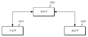
본 발명의 또 다른 일 실시예는, 송수신포인트로부터 기존의 제1범위 및 상기 제1범위보다 더 큰 값들을 포함하는 제2범위를 포함하는 전체 범위에서 일정한 간격으로 상향링크 사운딩 참조신호 전송전력의 특정 오프셋값을 지시하는 오프셋 정보를 수신하는 수신부, 상기 오프셋 정보로부터 상기 오프셋값을 사용한 상향링크 사운딩 참조신호의 전송전력으로 상향링크 사운딩 참조신호를 전송하도록 설정하는 제어부 및 상기 제어부에서 설정된 상향링크 사운딩 참조신호의 전송전력으로 상기 상향링크 사운딩 참조신호를 전송하는 송신부를 포함하는 단말을 제공한다.According to another embodiment of the present invention, an uplink sounding reference signal transmit power at regular intervals is included in a whole range including a first range and a second range including values larger than the first range. A receiver configured to receive offset information indicating a specific offset value of the controller, a controller configured to transmit an uplink sounding reference signal with a transmission power of an uplink sounding reference signal using the offset value from the offset information, and Provided is a terminal including a transmitter for transmitting the uplink sounding reference signal with a transmission power of an uplink sounding reference signal.
도 1은 실시예들이 적용되는 무선통신 시스템의 일 예를 도시한다.
도 2 및 도 3은 단말이 하나의 송수신포인트와 상/하향링크 데이터 전송하는 것을 도시한 도면이다.
도 4는 SRS 생성을 위한 단말의 구성을 나타내는 도면이다.
도 5는 SRS가 전송되는 심볼의 위치를 도시하고 있다.
도 6은 주파수 호핑을 하지 않는 SRS와 주파수 호핑하는 SRS를 도시하고 있다.
도 7 및 도 8은 상향링크 채널이 서빙 송수신포인트가 아닌 다른 송수신포인트로 전송되는 예를 도시한다.
도 9 및 도 10은 상향링크 관련 채널 중 일부가 서빙 송수신포인트가 아닌 다른 송수신포인트에 전송되는 예를 도시한다.
도 11 및 도 12는 상향링크 관련 채널 중 일부가 서빙 송수신포인트가 아닌 다른 송수신포인트에 전송되는 다른 예를 도시한다.
도 13 및 도 14은 상향링크 관련 채널 중 일부가 서빙 송수신포인트가 아닌 다른 송수신포인트에 전송되는 또 다른 예를 도시한다.
도 15는 본 발명의 실시예들에 따른 송수신포인트의 상향링크 사운딩 참조신호 전송전력 제어방법의 흐름도이다.
도 16은 본 발명의 다른 실시예에 따른 단말의 상향링크 사운딩 참조신호의 전송전력 제어방법의 흐름도이다.
도 17은 본 발명의 실시예에 따른 사운딩 참조신호 전송전력 제어방법으로 사운딩 참조신호가 서빙 송수신포인트에 전송되는 예를 도시한 도면이다.
도 18은 본 발명의 또 다른 실시예에 따른 송수신포인트의 구성을 보여주는 도면이다.
도 19은 본 발명의 또 다른 실시예에 따른 단말의 블록도를 도시한 도면이다.1 illustrates an example of a wireless communication system to which embodiments are applied.
2 and 3 are diagrams illustrating that a user equipment transmits one transmission / reception point and uplink / downlink data.
4 is a diagram illustrating a configuration of a terminal for generating an SRS.
5 shows the position of a symbol in which the SRS is transmitted.
6 shows an SRS that is not frequency hopping and an SRS that is frequency hopping.
7 and 8 illustrate an example in which an uplink channel is transmitted to a transmission / reception point other than a serving transmission / reception point.
9 and 10 illustrate an example in which some of the uplink-related channels are transmitted to transmission / reception points other than the serving transmission / reception points.
11 and 12 illustrate another example in which some of the uplink-related channels are transmitted to transmission / reception points other than the serving transmission / reception points.
13 and 14 illustrate another example in which some of uplink-related channels are transmitted to transmission / reception points other than the serving transmission / reception points.
15 is a flowchart illustrating a method for controlling uplink sounding reference signal transmission power of a transmission / reception point according to embodiments of the present invention.
16 is a flowchart illustrating a method of controlling a transmit power of an uplink sounding reference signal of a terminal according to another embodiment of the present invention.
17 is a diagram illustrating an example in which a sounding reference signal is transmitted to a serving transmission / reception point in a sounding reference signal transmission power control method according to an embodiment of the present invention.
18 is a diagram illustrating a configuration of a transmission and reception point according to another embodiment of the present invention.
19 is a block diagram of a terminal according to another embodiment of the present invention.
이하, 본 발명의 일부 실시예들을 예시적인 도면을 통해 상세하게 설명한다. 각 도면의 구성요소들에 참조부호를 부가함에 있어서, 동일한 구성요소들에 대해서는 비록 다른 도면상에 표시되더라도 가능한 한 동일한 부호를 가지도록 하고 있음에 유의해야 한다. 또한, 본 발명을 설명함에 있어, 관련된 공지 구성 또는 기능에 대한 구체적인 설명이 본 발명의 요지를 흐릴 수 있다고 판단되는 경우에는 그 상세한 설명은 생략한다.Hereinafter, some embodiments of the present invention will be described in detail with reference to exemplary drawings. It should be noted that, in adding reference numerals to the constituent elements of the drawings, the same constituent elements are denoted by the same reference symbols as possible even if they are shown in different drawings. In the following description of the present invention, a detailed description of known functions and configurations incorporated herein will be omitted when it may make the subject matter of the present invention rather unclear.
본 발명에서의 무선통신시스템은 음성, 패킷 데이터 등과 같은 다양한 통신 서비스를 제공하기 위해 널리 배치된다. 무선통신시스템은 사용자 단말(User Equipment, UE) 및 송수신포인트(Transmission/Reception point)을 포함한다. 본 명세서에서의 사용자 단말은 무선 통신에서의 단말을 의미하는 포괄적 개념으로서, WCDMA 및 LTE, HSPA 등에서의 UE(User Equipment)는 물론, GSM에서의 MS(Mobile Station), UT(User Terminal), SS(Subscriber Station), 무선기기(wireless device) 등을 모두 포함하는 개념으로 해석되어야 할 것이다.The wireless communication system in the present invention is widely deployed to provide various communication services such as voice, packet data and the like. The wireless communication system includes a user equipment (UE) and a transmission / reception point. In the present specification, a user terminal is a generic concept meaning a terminal in wireless communication. In addition, user equipment (UE) in WCDMA, LTE, and HSPA, as well as mobile station (MS) in GSM, user terminal (UT), and SS It should be interpreted as a concept that includes a subscriber station, a wireless device, and the like.
송수신포인트는 일반적으로 사용자 단말과 통신하는 지점(station)을 말하며, 기지국(Base Station, BS) 또는 셀(cell), 노드-B(Node-B), eNB(evolved Node-B), 섹터(Sector), 싸이트(Site), BTS(Base Transceiver System), 액세스 포인트(Access Point), 릴레이 노드(Relay Node), RRH(Remote Radio Head), RU(Radio Unit), 안테나 등 다른 용어로 불릴 수 있다.A transmission / reception point generally refers to a station communicating with a user terminal, and includes a base station (BS) or a cell, a node, a node-B, an evolved node-B, and a sector. ), A site, a base transceiver system (BTS), an access point, an access point, a relay node, a remote radio head (RRH), a radio unit (RU), and an antenna.
즉, 본 명세서에서 송수신포인트 또는 기지국, 셀(cell)은 CDMA에서의 BSC(Base Station Controller), WCDMA의 NodeB, LTE에서의 eNB 또는 섹터(싸이트) 등이 커버하는 일부 영역 또는 기능을 나타내는 포괄적인 의미로 해석되어야 하며, 메가셀, 매크로셀, 마이크로셀, 피코셀, 펨토셀 및 릴레이 노드(relay node), RRH(Remote Radio Head), RU(Radio Unit) 통신범위 등 다양한 커버리지 영역을 모두 포괄하는 의미이다. That is, in the present specification, a transmission / reception point or a base station and a cell refer to a comprehensive area representing a partial area or function covered by a base station controller (BSC) in CDMA, a NodeB in WCDMA, an eNB or a sector (site) in LTE, and the like. It should be interpreted as meaning and encompasses various coverage areas such as megacell, macrocell, microcell, picocell, femtocell and relay node, remote radio head (RRH), and radio unit (RU) communication range. to be.
본 명세서에서 사용자 단말과 송수신포인트는 본 명세서에서 기술되는 기술 또는 기술적 사상을 구현하는데 사용되는 두 가지 송수신 주체로 포괄적인 의미로 사용되며 특정하게 지칭되는 용어 또는 단어에 의해 한정되지 않는다. 사용자 단말과 송수신포인트는, 본 발명에서 기술되는 기술 또는 기술적 사상을 구현하는데 사용되는 두 가지(Uplink 또는 Downlink) 송수신 주체로 포괄적인 의미로 사용되며 특정하게 지칭되는 용어 또는 단어에 의해 한정되지 않는다. 여기서, 상향링크(Uplink, UL, 또는 업링크)는 사용자 단말에 의해 기지국으로 데이터를 송수신하는 방식을 의미하며, 하향링크(Downlink, DL, 또는 다운링크)는 기지국에 의해 사용자 단말로 데이터를 송수신하는 방식을 의미한다.In this specification, a user terminal and a transmission / reception point are used in a generic sense as two transmission / reception entities used to implement the technology or technical idea described in the present specification, and are not limited by the terms or words specifically referred to. The user terminal and the transmission and reception point is used in a comprehensive sense as two (uplink or downlink) transmission and reception subjects used to implement the technology or the technical idea described in the present invention and are not limited by the terms or words specifically referred to. Here, the uplink (Uplink, UL, or uplink) refers to a method for transmitting and receiving data to the base station by the user terminal, the downlink (Downlink, DL, or downlink) means to transmit and receive data to the user terminal by the base station It means the way.
무선통신시스템에 적용되는 다중 접속 기법에는 제한이 없다. CDMA(Code Division Multiple Access), TDMA(Time Division Multiple Access), FDMA(Frequency Division Multiple Access), OFDMA(Orthogonal Frequency Division Multiple Access), OFDM-FDMA, OFDM-TDMA, OFDM-CDMA와 같은 다양한 다중 접속 기법을 사용할 수 있다. 본 발명의 일 실시예는 GSM, WCDMA, HSPA를 거쳐 LTE 및 LTE-advanced로 진화하는 비동기 무선통신과, CDMA, CDMA-2000 및 UMB로 진화하는 동기식 무선 통신 분야 등의 자원할당에 적용될 수 있다. 본 발명은 특정한 무선통신 분야에 한정되거나 제한되어 해석되어서는 아니 되며, 본 발명의 사상이 적용될 수 있는 모든 기술분야를 포함하는 것으로 해석되어야 할 것이다.There are no restrictions on multiple access schemes applied to wireless communication systems. Various multiple access schemes such as Code Division Multiple Access (CDMA), Time Division Multiple Access (TDMA), Frequency Division Multiple Access (FDMA), Orthogonal Frequency Division Multiple Access (OFDMA), OFDM-FDMA, OFDM- Can be used. An embodiment of the present invention can be applied to asynchronous wireless communication that evolves into LTE and LTE-advanced via GSM, WCDMA, and HSPA, and synchronous wireless communication that evolves into CDMA, CDMA-2000, and UMB. The present invention should not be construed as limited to or limited to a specific wireless communication field and should be construed as including all technical fields to which the idea of the present invention can be applied.
상향링크 전송 및 하향링크 전송은 서로 다른 시간을 사용하여 전송되는 TDD(Time Division Duplex) 방식이 사용될 수 있고, 또는 서로 다른 주파수를 사용하여 전송되는 FDD(Frequency Division Duplex) 방식이 사용될 수 있다.A TDD (Time Division Duplex) scheme in which uplink and downlink transmissions are transmitted using different time periods, or an FDD (Frequency Division Duplex) scheme in which they are transmitted using different frequencies can be used.
본 명세서에서 셀(cell)은 송수신포인트로부터 전송되는 신호의 커버리지 또는 송수신포인트(transmission point 또는 transmission/reception point)로부터 전송되는 신호의 커버리지를 가지는 요소반송파(component carrier), 그 송수신포인트 자체를 의미할 수 있다. 본 명세서에서 송수신포인트는 신호를 송신하는 송신포인트(transmission point) 또는 신호를 수신하는 수신포인트(reception point), 이들의 결합(transmission/reception point)을 의미한다.In the present specification, a cell means a component carrier having a coverage of a signal transmitted from a transmission / reception point or a signal transmitted from a transmission point or a transmission / reception point, and the transmission / reception point itself. Can be. In the present specification, a transmission / reception point refers to a transmission point for transmitting a signal or a reception point for receiving a signal and a combination thereof.
도 1은 실시예들이 적용되는 무선통신 시스템의 일 예를 도시한다.1 illustrates an example of a wireless communication system to which embodiments are applied.
도 1을 참조하면, 실시예들이 적용되는 무선통신 시스템(100)은 둘 이상의 송수신포인트들이 협력하여 신호를 전송하는 다중 포인트 협력형 송수신 시스템(coordinated multi-point transmission/reception System; CoMP 시스템) 또는 협력형 다중 안테나 전송방식(coordinated multi-antenna transmission system), 협력형 다중 셀 통신시스템일 수 있다. CoMP 시스템(100)은 적어도 두개의 송수신포인트(110, 112)와 단말들(120, 122)을 포함할 수 있다. Referring to FIG. 1, a
송수신포인트는 기지국 또는 매크로 셀(macro cell 또는 macro node, 110, 이하 'eNB'라 함)과, eNB(110)에 광케이블 또는 광섬유로 연결되어 유선 제어되는, 높은 전송파워를 갖거나 매크로 셀영역 내의 낮은 전송파워를 갖는 적어도 하나의 피코 셀(pico cell, 112, 이하 'RRH'라 함)일 수도 있다. eNB(110)과 RRH(112)는 동일한 셀 ID를 가질 수도 있고 서로 다른 셀 ID를 가질 수도 있다. The transmit / receive point is a base station or macro cell (macro cell or
이하에서 하향링크(downlink)는 송수신포인트(110, 112)에서 단말(120)로의 통신 또는 통신 경로를 의미하며, 상향링크(uplink)는 단말(120)에서 송수신포인트(110, 112)으로의 통신 또는 통신 경로를 의미한다. 하향링크에서 송신기는 송수신포인트(110, 112)의 일부분일 수 있고, 수신기는 단말(120, 122)의 일부분일 수 있다. 상향링크에서 송신기는 단말(120)의 일부분일 수 있고, 수신기는 송수신포인트(110, 112)의 일부분일 수 있다. Hereinafter, downlink (downlink) means a communication or communication path from the transmission and reception points (110, 112) to the
도 2 및 도 3은 단말이 하나의 송수신포인트와 상/하향링크 데이터 전송하는 것을 도시한 도면이다.2 and 3 are diagrams illustrating that a user equipment transmits one transmission / reception point and uplink / downlink data.
도 2 및 도 3을 참조하면 각 송수신포인트의 셀 아이디가 같거나 서로 다른 상황에서 단말은 상/하향링크 신호 모두를 하나의 송수신포인트와 주고받을 수 있다.Referring to FIGS. 2 and 3, when a cell ID of each transmit / receive point is the same or different, the terminal may exchange both uplink / downlink signals with one transmit / receive point.
또한, LTE, LTE-A와 같은 시스템에서는 하나의 반송파 또는 반송파 쌍을 기준으로 상향링크와 하향링크를 구성하여 규격을 구성한다. 상향링크와 하향링크는, PDCCH(Physical Downlink Control CHannel), PCFICH(Physical Control Format Indicator CHannel), PHICH(Physical Hybrid ARQ Indicator CHannel), PUCCH(Physical Uplink Control CHannel) 등과 같은 제어채널을 통하여 제어정보를 전송하고, PDSCH(Physical Downlink Shared CHannel), PUSCH(Physical Uplink Shared CHannel) 등과 같은 데이터채널로 구성되어 데이터를 전송한다. 본 명세서에서 PDCCH는 EPDCCH를 포함하는 개념이다.In systems such as LTE and LTE-A, the uplink and downlink are configured on the basis of one carrier or carrier pair to form a standard. The uplink and downlink transmit control information through a control channel such as a Physical Downlink Control Channel (PDCCH), a Physical Control Format Indicator CHannel (PCFICH), a Physical Hybrid ARQ Indicator CHannel (PHICH), a Physical Uplink Control CHannel And a data channel such as a Physical Downlink Shared CHannel (PDSCH), a Physical Uplink Shared CHannel (PUSCH), and the like. In the present specification, the PDCCH is a concept including an EPDCCH.
송수신포인트(110, 112) 중 하나인 eNB(110)은 단말들(120, 122)로 하향링크 전송을 수행할 수 있다. eNB(110)은 유니캐스트 전송(unicast transmission)을 위한 주 물리 채널인 물리 하향링크 공유채널(Physical Downlink Shared Channel, PDSCH), 그리고 PDSCH의 수신에 필요한 스케줄링 등의 하향링크 제어 정보 및 상향링크 데이터채널(예를 들면 물리 상향링크 공유채널(Physical Uplink Shared Channel, PUSCH) 의 전송을 위한 스케줄링 승인 정보를 전송하기 위한 물리 하향링크 제어채널(Physical Downlink Control Channel, PDCCH)을 전송할 수 있다. 이하에서는, 각 채널을 통해 신호가 송수신 되는 것을 해당 채널이 송수신되는 형태로 기재하기로 한다. The
제1단말(120,UE1)은 eNB(110)로 상향링크 신호를 전송할 수 있다. 제2단말(122, UE2)은 송수신포인트(110, 112) 중 하나인 RRH(112)로 상향링크 신호를 전송할 수 있다. 이때 제1단말(120)은 RRH(112)로 상향링크 신호를 전송하고 제2단말(122)는 eNB(110)로 상향링크 신호를 전송할 수 있다. 또한 단말들의 개수는 두개 이상일 수도 있다. 다만 아래 실시예에서 단말들의 개수는 2개이고 하나의 단말은 eNB(110)로, 다른 단말은 RRH(112)로 상향링크 신호를 전송하는 것으로 예시적으로 설명한다.The
이하에서는 PUCCH, PUSCH, PDCCH 및 PDSCH 등과 같은 채널을 통해 신호가 송수신되는 상황을 'PUCCH, PUSCH, PDCCH 및 PDSCH를 전송, 수신한다'는 형태로 표기하기도 한다.Hereinafter, a situation in which a signal is transmitted / received through a channel such as PUCCH, PUSCH, PDCCH, and PDSCH is expressed as 'PUCCH, PUSCH, PDCCH and PDSCH are transmitted and received'.
현재의 무선통신 방식 중 하나인 LTE 통신시스템에서는 상향링크에 복조 참조신호(Demodulation Reference Signal; DMRS, DM-RS) 및 사운딩 참조신호 (Sounding Reference Signal; SRS)가 정의되어 있으며, 하향링크에 3가지의 참조신호(Reference Signal; RS)가 정의되어 있으며, 셀고유 참조신호(Cell-specific Reference Signal; CRS)와, MBSFN 참조신호 (Multicast/Broadcast over Single Frequency Network Reference Signal; MBSFN-RS) 및 단말 고유 참조신호(UE-specific Reference Signal)가 그것이다.In the LTE communication system, which is one of the current wireless communication methods, a demodulation reference signal (DMRS, DM-RS) and a sounding reference signal (SRS) are defined in uplink, and 3 in the downlink. Reference Signals (RS) are defined, Cell-specific Reference Signals (CRS), MBSFN Reference Signals (Multicast / Broadcast over Single Frequency Network Reference Signals (MBSFN-RS) and UE) It is a UE-specific reference signal.
무선통신 시스템에서 단말은 상향링크(uplink) 전송시 데이터채널의 복조를 위한 채널 정보를 파악하기 위해 상향링크 복조신호(UL DMRS 또는 UL DM-RS)를 매 슬롯(slot)마다 전송하게 된다. PUSCH(Physical Uplink Shared CHannel)와 연계된 상향링크 DM-RS의 경우 매 슬롯마다 하나의 심볼에 대하여 참조신호를 전송하며, PUCCH(Physical Uplink Control CHannel)과 연계된 상향링크 DM-RS의 경우 PUCCH의 방식에 따라 PUCCH 포맷 1/1a/1b의 경우에는 매 슬롯마다 3개의 심볼 또는 PUCCH 포맷 2/2a/2b/3의 경우에는 매 슬롯마다 2개의 심볼에 대하여 참조신호를 전송하게 된다. In a wireless communication system, a terminal transmits an uplink demodulation signal (UL DMRS or UL DM-RS) every slot in order to determine channel information for demodulation of a data channel during uplink transmission. In case of an uplink DM-RS associated with a PUSCH (Physical Uplink Shared CHannel), a reference signal is transmitted for one symbol in every slot, and in case of an uplink DM-RS associated with a physical uplink control channel (PUCCH), a PUCCH According to the scheme, three symbols are transmitted in every slot in the
이 중 상향링크 사운딩 참조신호(SRS)는 상향링크 주파수 의존적인 스케줄링을 위해 상향링크 채널 상태를 측정하고 TDD 시스템에서 채널가역성(channel reciprocity)를 이용하여 하향링크 빔포밍(DL beamforming)을 위해 상/하향링크의 채널 상태를 측정하는데 사용된다.The uplink sounding reference signal (SRS) measures an uplink channel state for uplink frequency dependent scheduling and uses uplink channelforming for DL beamforming using channel reciprocity in a TDD system. Used to measure the channel state of the downlink.
상향링크 SRS의 경우, 무선통신시스템(100)에서 임의의 송수신포인트 또는 임의의 셀로부터 단말에게 단말이 전송하는 SRS의 생성을 위한 파라미터들, 예를 들어 SRS의 셀-특정 SRS 대역(cell specific SRS bandwidth), 전송 comb(transmission comb)(2 서브캐리어 스페이싱(subcarrier spacing) 간격으로 할당된 주파수 위치지정, 예를 들어 0(even subcarriers) 또는 1(odd subcarriers)), 단말-특정 SRS 대역(UE-specific SRS bandwidth), 호핑 관련 구성 파라미터들, 주파수 도메인 위치(frequency domain position), 주기(periodicity), 서브프레임 구성(어떤 서브프레임에서 SRS를 전송해야 할지를 지정), 안테나 구성(SRS를 전송하는 안테나의 수를 지정, 안테나 포트의 수), 베이스 시퀀스 인덱스(해당 SRS 생성을 위한 SRS 시퀀스 인덱스는 PUCCH에서 사용하는 시퀀스 그룹 넘버 u와 시퀀스 호핑 구성에 따라 정해지는 시퀀스 넘버 v에 따라 결정됨), 사이클릭 쉬프트 인덱스(SRS 생성시 사용되는 참조신호로서 사이클릭 쉬프트 인덱스) 등을 해당 송수신포인트가 단말(120)에게 RRC 파라미터로서 전송하고 단말(120)은 해당 정보를 수신하여 상향링크 SRS를 전송하게 된다.In the case of the uplink SRS, parameters for generating an SRS transmitted by the UE from an arbitrary transmission point or an arbitrary cell in the
추가적으로 주기적인 SRS와 함께 비주기적 SRS가 정의되어 있다. 해당 비주기적 SRS도 주기적인 SRS와 유사하게 해당 비주기적 SRS 생성을 위해 사용되는 각종 파라미터들은 무선통신시스템(100)에서 사용하는 바와 같이 단말이 전송하는 비주기적 SRS의 생성을 위한 파라미터, 예를 들어 비주기적 SRS의 단말-특정 SRS 대역, 전송 comb, 주파수 도메인 위치, 주기, 서브프레임 구성, 안테나 구성, 베이스 시퀀스 인덱스, 사이클릭 쉬프트 인덱스 등을 임의의 송수신포인트가 단말(120)에게 RRC 파라미터로서 전송한다.In addition, aperiodic SRS is defined along with periodic SRS. Similar to the periodic SRS, the corresponding aperiodic SRS is a parameter for generating an aperiodic SRS transmitted by the terminal as used in the
추가적으로 비주기적 SRS를 전송하기 위해 임의의 송수신포인트는 단말(120)에게 동적으로 PDCCH를 통하여 비주기적 SRS의 전송을 트리거링하고, 해당 단말(120)은 PDCCH에 의한 트리거링과 RRC 파라미터들을 수신하여 상향링크 비주기적 SRS를 전송하게 된다.아래에서는 SRS의 생성과 전송과정을 구체적으로 설명한다.Additionally, in order to transmit the aperiodic SRS, any transmission / reception point dynamically triggers the transmission of the aperiodic SRS through the PDCCH to the terminal 120, and the terminal 120 receives the triggering by the PDCCH and the RRC parameters to uplink. Aperiodic SRS is transmitted. The generation and transmission process of the SRS will be described in detail below.
SRS 시퀀스는 수학식 1 및 2와 같이 Zadoff-Chu 시퀀스를 기반으로 한 베이스 시퀀스(base sequence)( 
![]()
![]()


베이스 시퀀스는 시퀀스 그룹 넘버 u, 그룹 내의 베이스 시퀀스 넘버 v, 그리고 시퀀스의 길이인 n에 의하여 서로 다르게 생성된다. The base sequence is generated differently by the sequence group number u, the base sequence number v in the group, and n, the length of the sequence.
시퀀스 그룹 호핑(sequence Group hopping)은 단말에게 할당되는 RB의 수와 관계없이 30개의 시퀀스 그룹을 슬롯마다 호핑한다. Sequence group hopping hops 30 sequence groups per slot regardless of the number of RBs allocated to the UE.
구체적으로 슬롯 ns에서 시퀀스 그룹 넘버 u는 그룹 호핑 패턴 fgh(ns)와 시퀀스 쉬프트 패턴 fss에 의해서 아래 수학식 3에 의해 결정된다.Specifically, the sequence group number u in slot n s is determined by the equation (3) below by a group hopping pattern f gh (n s) and the sequence shift pattern f ss.

PUCCH와 PUSCH는 동일한 시퀀스 그룹 호핑 패턴 ![]()

![]()
그룹 호핑 패턴 ![]()
![]()

![]()


![]()
이 때 가상의 셀 아이디 (


시퀀스 쉬프트 패턴 ![]()

![]()
시퀀스 호핑은 길이가 6RB들 이상( 

길이가 6RB들 이상(

![]()

![]()
사이클릭 쉬프트 값 

사이클릭 쉬프트 값을 계산할 때 사용되는 


도 4는 SRS 생성을 위한 단말의 구성을 도시한다.4 illustrates a configuration of a terminal for generating an SRS.
수학식 2의 베이스 시퀀스와 수학식 6의 

전술한 바와 같이 


수학식 1에 의해 생성된 SRS 시퀀스는 서브프레임의 해당 심볼에 매핑되며, 도 4의 리소스 요소 맵퍼(resource element mapper, 420)를 통해 수행된다.The SRS sequence generated by
도 5는 SRS가 전송되는 심볼의 위치를 도시하고 있다. 도 6은 주파수 호핑을 하지 않는 SRS와 주파수 호핑하는 SRS를 도시하고 있다.5 shows the position of a symbol in which the SRS is transmitted. 6 shows an SRS that is not frequency hopping and an SRS that is frequency hopping.
도 5 및 도 6을 참조하면, SRS는 서브프레임의 마지막 심볼에 전송된다. 주파수 영역상에서 SRS 전송은 주파수 영역 스케줄링을 위해 관심있는 주파수 대역을 커버해야 한다. 도 6의 (a)에 도시한 바와 같이, 단일 SRS 전송으로 관심있는 전체 주파수 대역에 대한 채널 품질을 추정할 수 있도록 충분히 넓은 SRS 전송을 할 수 있다. 한편, 도 6의 (b)에 도시한 바와 같이, 협대역의 SRS를 주파수 영역에서 호핑하면서 전송함으로써 이러한 SRS 전송들이 합쳐져서 관심있는 전체 주파수 대역을 커버하도록 할 수도 있다.5 and 6, the SRS is transmitted in the last symbol of the subframe. SRS transmission in the frequency domain should cover the frequency band of interest for frequency domain scheduling. As shown in (a) of FIG. 6, the SRS transmission can be sufficiently wide to estimate the channel quality for the entire frequency band of interest with a single SRS transmission. On the other hand, as shown in (b) of FIG. 6, by transmitting the narrow band SRS in the frequency domain, these SRS transmissions may be combined to cover the entire frequency band of interest.
전술한 바와 같이 SRS를 자원 요소에 매핑이 완료하면 SC FDMA 생성기(SC FDMA generator, 도 4에 미도시)를 통해 SC-FDMA 심볼을 생성하여 SRS 신호를 송수신포인트에 전송한다.As described above, when the SRS is mapped to the resource element, the SC-FDMA symbol is generated through an SC FDMA generator (not shown in FIG. 4) to transmit the SRS signal to the transmission / reception point.
SRS가 전송되는 특정 서브프레임은 주기적(periodic) 또는 비주기적(aperiodic)으로 설정될 수 있다. 예를 들면, 아래의 표 1(주파수 분할 방식(Frequency Division Duplex, FDD)) 또는 표 2(시분할 방식(Time Division Duplex, TDD))에서와 같이 정의되는 셀-특정된(cell-specific) SRS 전송 가능한 서브프레임들 중에서, SRS는 각 단말 별로 특정 주기와 오프셋을 가지는 서브프레임에서 주기적으로 전송될 수 있다. 이러한 SRS를 주기적 SRS(periodic SRS) 또는 트리거 타입 0 SRS라 부를 수 있다. 또는, SRS는 비주기적으로 설정되는 특정 서브프레임에서 전송될 수 있다. 이러한 SRS를 비주기적 SRS(aperiodic SRS) 또는 트리거 타입 1 SRS라 부를 수 있다.The specific subframe in which the SRS is transmitted may be set periodically or aperiodicly. For example, cell-specific SRS transmission as defined in Table 1 (Frequency Division Duplex (FDD)) or Table 2 (Time Division Duplex (TDD)) below. Among the possible subframes, the SRS may be periodically transmitted in a subframe having a specific period and offset for each terminal. Such an SRS may be called a periodic SRS or a


이상 SRS 시퀀스의 생성과 전송과정에 대해 도 4 내지 도 6을 참조하여 설명하였다. 이하에서는 상향링크 사운딩 참조신호의 전송전력 제어방법에 대하여 설명한다.The generation and transmission process of the SRS sequence has been described with reference to FIGS. 4 to 6. Hereinafter, a transmission power control method of an uplink sounding reference signal will be described.
본 발명의 실시예에 따른 사운딩 참조신호 전송전력 제어방법에서 송수신포인트(c)로 서브프레임(i)에서 전송되는 단말의 사운딩 참조신호의 전송전력( ![]()
![]()

수학식 7에서, PCMAX ,c(i)는 단말(120)의 최대 전송전력으로, 사운딩 참조신호의 전송전력은 PCMAX,c(i)에 제한된다.In Equation 7, P CMAX , c (i) is the maximum transmit power of the terminal 120, and the transmit power of the sounding reference signal is limited to P CMAX, c (i).
또한 P_SRS_OFFSET,c(m)는 오프셋값으로서, 서빙 셀(c)에서 특정 m에 대해 RRC 시그널링 혹은 상위계층에 의해 설정된다. 이때 오프셋값의 범위나 m값에 대해서는 후술한다. In addition, P_SRS_OFFSET, c (m) is an offset value and is set by RRC signaling or higher layer for a specific m in the serving cell c. At this time, the range and the m value of the offset value will be described later.
MSRS ,c는 자원 블록의 수로 표현되는 서빙 셀(c)에 대한 서브프레임(i)에서 SRS 전송의 대역폭이다.M SRS , c is the bandwidth of the SRS transmission in subframe (i) for the serving cell (c) expressed by the number of resource blocks.
P0 _ PUSCH ,c(j)는 준정적 베이스 레벨(semi-static base level)로서, 공통 전력 레벨( 

단말-특정 전력 레벨(

다르게 말하자면, P0 _ PUSCH ,c(j)는 PUSCH를 전송함에 있어 보장되어야 하는 수신 전력에 대한 인자이다. P0 _ PUSCH는 기지국에서 요구되는 수신 SINR(Signal-to-interference and noise ratio)을 얻기 위해 필요한 수신 전력을 의미한다. P0 _ PUSCH는 기지국에서 간섭 레벨에 기초하여 결정되는 값이고, 간섭은 시스템 구축 상황에 따라 달라질 수도 있고 망 내의 부하가 시간에 따라 변하므로 시간에 따라서 달라질 수도 있다.In other words, P 0 _ PUSCH , c (j) is a factor for the received power that should be guaranteed in transmitting the PUSCH. P 0 _ PUSCH refers to a reception power required for obtaining a reception signal-to-interference and noise ratio (SINR) required by a base station. P 0 _ PUSCH is a value determined based on the interference level at the base station, and the interference may vary depending on the system construction situation and may vary depending on time since the load in the network changes over time.
준-지속적(semi-persistent) 승인(grant)에 대한 PUSCH (재)전송에 대해 j=0이고, 동적으로 스케줄링되는(dynamic scheduled) 승인에 대한 PUSCH (재)전송에 대해 j=1이며, 랜덤 액세스 응답(random access response) 승인에 대한 PUSCH (재)전송에 대해 j=2이다. 이 경우 ![]()
![]()
및 


만약 SRS 심볼에 대한 단말의 총 전송전력이 


![]()


![]()
αc(j)는 경로 손실을 보상하는 정도를 나타낸다. αc(j)가 1이면 경로 손실이 완전히 보상되는 것을 의미하고, αc(j)가 1보다 작으면 경로 손실이 완전히 보상되지 않은 것을 의미한다. j=0 또는 1일 때, αc(j)![]()
![]()
PLc는 서빙 셀(c)에 대해 단말(10)에서 계산된 하향링크 경로-손실(path loss) 추정값으로서, PLc = (기준 신호 전송 전력 - 기준 신호 수신 전력(Reference Signal Received Power, RSRP))의 식으로 결정될 수 있다.PL c is a downlink path loss estimated value calculated by the terminal 10 with respect to the serving cell c, and PL c = (Reference Signal Received Power (RSRP) Can be determined by the following equation.
fc(i)는 명시적인 전력 제어 명령을 통해 직접적으로 PUSCH 전송 전력을 조절하기 위한 값이다. f(i)는 누적값으로서, 특정 양 만큼 증가 또는 감소시킨다. f(i)는 상향링크 스케줄링 승인(UL grant)에 들어있다.f c (i) is a value for directly adjusting the PUSCH transmit power through an explicit power control command. f (i) is a cumulative value, increasing or decreasing by a certain amount. f (i) is in UL grant.
보다 상세하게는, ![]()


![]()
![]()
![]()
본 발명의 실시예에 따른 사운딩 참조신호 전송전력 제어방법에서는 전술한 수학식 7의 사운딩 참조신호 전송전력을 결정하는 변수들 중 P_SRS_OFFSET,c(m)가 종래와 다르게 확장될 수 있다.In the sounding reference signal transmission power control method according to an embodiment of the present invention, P_SRS_OFFSET, c (m) among the variables for determining the sounding reference signal transmission power of Equation 7 may be extended differently from the conventional method.
좀 더 구체적으로 오프셋값에 의한 SRS 전송전력 지정이 종래보다 넓은 범위에서 지정되면서 종래 단말들과의 호환성을 위해 P_SRS_OFFSET,c(m)은 종래 오프셋값에 의해 지정가능 하였던 전력범위인 제 1 범위와 이러한 제 1 범위보다 더 넓은 범위에서 전력값이 지정가능하도록 하는 제 2 범위를 포함하는 범위에서 전력값을 지정하도록 정해질 수 있다.More specifically, the SRS transmission power designation by the offset value is specified in a wider range than the conventional one, and for compatibility with the conventional terminals, P_SRS_OFFSET, c (m) is the first range, which is the power range previously specified by the offset value, and It may be arranged to specify a power value in a range including a second range that allows the power value to be specified in a range wider than this first range.
또한 본 발명의 실시예에 따른 사운딩 참조신호 전송전력 제어방법에서는 전술한 수학식 7의 사운딩 참조신호 전송전력을 결정하는 변수들 중 경로손실에 대한 변수 PLc가 종래와 다르게 설정될 수 있다.In addition, in the sounding reference signal transmission power control method according to an embodiment of the present invention, the variable PL c for the path loss among the variables for determining the sounding reference signal transmission power of Equation 7 may be set differently from the conventional method. .
좀 더 구체적으로 수학식 7에서 경로손실 추정값인 PLc 은 CSI-RS를 이용하여 추정된 경로손실을 추정할 수도 있고, 하향링크에서 사용하는 CRS(cell specific RS)와 CSI-RS를 모두 이용하여 경로손실을 추정할 수도 있다.More specifically, PL c which is an estimated path loss in Equation 7 The estimated path loss may be estimated using the CSI-RS, or the path loss may be estimated using both the cell specific RS (CRS) and the CSI-RS used in the downlink.
전술한 본 발명의 실시예에 따른 사운딩 참조신호 전송전력 제어방법은 사운딩 참조신호가 단말(120)에 하향링크 전송하는 서빙 송수신 포인트(110)로 전송되는 경우 뿐만 아니라 사운딩 참조신호가 서빙 송수신 포인트가 아닌 다른 송수신 포인트 예를 들어 RRH(112)로 전송되는 경우에도 적용될 수 있으며 전술한 두 가지 경우를 구분하여 특정 경우에만 적용될 수도 있다.The sounding reference signal transmission power control method according to the embodiment of the present invention described above is not only the case in which the sounding reference signal is transmitted to the serving transmission /
따라서 본 발명의 실시예에 따른 사운딩 참조신호 전송전력 제어방법에 대한 보다 상세한 설명에 앞서 우선 사운딩 참조신호의 수신대상이 서빙 송수신 포인트(110)와 달라질 수 있는 환경에 대하여 설명하겠다.Therefore, prior to a more detailed description of the method for controlling the sounding reference signal transmission power according to the embodiment of the present invention, an environment in which the reception target of the sounding reference signal may be different from the serving transmission /
종래의 송수신포인트는 크게 디지털 신호 처리부와 무선 신호 처리부가 하나의 물리적 시스템 내에 함께 포함한다. 그러나 이러한 시스템은 모든 처리부를 포함하는 송수신포인트를 셀에 다 설치하여야 하므로 셀 설계의 최적화에 한계점이 있었다.Conventional transmission and reception points largely include a digital signal processor and a wireless signal processor in one physical system. However, such a system has a limitation in optimizing a cell design because all transmission and reception points including all processing units must be installed in a cell.
위에 언급한 문제점의 개선을 위해 본 발명의 실시예들이 적용되는 무선통신시스템(100)에서는, 송수신포인트가 새롭게 제안된 CCC(Cloud Communication Center)에 따라 그 기능이 분리되어 집중될 수 있다. 일 예로 송수신포인트의 디지털 신호 처리부(DU, Digital Unit)와 무선 신호를 송/수신하는 무선신호 처리부(RU, Radio Unit)를 분리해 DU는 전화국, 예를 들어 eNB에 집중 배치하고, RU는 서비스 지역, 예를 들어 RRH에 설치할 수 있다.In the
전술한 환경에서 단말은 여러 개의 RU들의 커버리지 내에서 위치하거나 여러 개의 RU들의 커버리지를 이동하기도 하고 또한 여러 RU들의 셀 경계(cell edge)에서 RU로부터 서비스를 제공받게 된다. 즉, 단말이 위치하거나 이동하는 중에 RU가 전송하는 하향링크 전송신호의 커버리지와 단말이 RU에게 전송해야 해야 하는 상향링크의 커버리지가 달라질 수 있다. 즉 단말의 하향링크에 대한 지오메트리(geometry)와 상향링크의 지오메트리(geometry)가 달라질 수 있으며, 특정 RU로부터 수신된 하향링크로 데이터 채널 및 컨트롤 채널을 수신하는 RU와는 다른 RU로의 상향링크 전송이 가능할 수 있다. In the above-described environment, the terminal may be located within the coverage of several RUs or move the coverage of several RUs, and may also receive service from the RU at the cell edge of the various RUs. That is, the coverage of the downlink transmission signal transmitted by the RU and the coverage of the uplink that the terminal should transmit to the RU may be different while the terminal is located or moving. That is, the geometry of the downlink and the geometry of the uplink may be different, and the uplink transmission to the RU different from the RU receiving the data channel and the control channel through the downlink received from the specific RU may be possible. Can be.
또한 매크로 셀 구현(macro cell deployment)와 다양한 스몰 셀 구현(small cell deployment)를 고려하는 이종망(heterogeneous network) 상황에서도 해당 경우는 유사할 수 있다. 즉 매크로 셀(macro cell)의 커버리지와 스몰 셀의 커버리지가 다르고 매크로 셀로부터 전송되는 하향링크의 데이터 및 컨트롤 채널을 수신한 단말이 상향링크에 대해 지오메트리가 더 좋은 스몰 셀 커버리지로의 상향링크 데이터 및 컨트롤 전송을 수행하게 함으로써 해당 하향링크에 대해서는 상향링크 컨트롤 정보에 대한 신뢰성을 높임으로서 하향링크의 데이터 전송속도를 향상시키게 되고, 상향링크에 대해서는 컨트롤 정보에 대한 신뢰성 및 상향링크 데이터 전송에 대해서도 신뢰성을 높임으로써 상향링크 전송속도를 향상시키게 할 수 있다.In addition, the case may be similar in a heterogeneous network situation in which macro cell deployment and various small cell deployments are considered. That is, the UE receiving the downlink data transmitted from the macro cell and the control channel having different coverage of the macro cell and the small cell, and having uplink data to the small cell coverage having better geometry for the uplink and By performing control transmission, the downlink data transmission speed is improved by increasing the reliability of uplink control information for the downlink, and the reliability of the control information and uplink data transmission for the uplink are also improved. By increasing the uplink transmission rate can be improved.
따라서 본 발명이 적용되는 시스템에서는 전술한 바와 같이 사운딩 참조신호의 수신대상이 서빙 송수신 포인트(110) 뿐만 아니라 채널 상태에 따라서 다른 송수신 포인트 예컨데 RRH(112)로 지정될 수 있도록 사운딩 참조신호 시퀀스 생성을 위한 가상 셀 아이디 

이하에서는 전술한 본 발명이 적용되는 시스템에서 사운딩 참조신호가 전송되는 여러가지 예에 관하여 도면을 참조하여 설명한다.Hereinafter, various examples of transmitting a sounding reference signal in a system to which the present invention is applied will be described with reference to the accompanying drawings.
도 7 및 도 8은 상향링크 관련 채널이 모두 서빙 송수신포인트가 아닌 다른 송수신포인트로 전송되는 예를 도시한다.7 and 8 illustrate an example in which all uplink-related channels are transmitted to transmission / reception points other than the serving transmission / reception points.
도 7 및 도 8를 참조하면 각 송수신포인트의 셀 아이디가 같거나 서로 다른 상황에서 상향링크 컨트롤 채널과 데이터 채널은 해당 단말이 속한 송수신포인트(110)로부터 수신하고, 상향링크 관련 채널은 모두 해당 단말(120)에게 지오메트리 및 채널 품질이 더 나은 송수신포인트(112)로 전송되게 된다.7 and 8, the uplink control channel and the data channel are received from the transmit / receive
도 9 및 도 10은 상향링크 관련 채널 중 일부가 서빙 송수신포인트가 아닌 다른 송수신포인트에 전송되는 예를 도시한다.9 and 10 illustrate an example in which some of the uplink-related channels are transmitted to transmission / reception points other than the serving transmission / reception points.
도 9 및 도 10을 참조하면, 각 송수신포인트의 셀 아이디가 같거나 서로 다른 상황에서 하향링크 컨트롤 채널과 데이터 채널은 해당 단말(120)이 속한 송수신포인트로(110)부터 수신하고, 상향링크 관련 채널 중 하향링크 전송에 대한 A/N을 전송하는 PUCCH 채널과 상향링크 데이터 채널 PUSCH는 해당 송수신포인트(110) 또는 다른 송수신포인트(112)로 전송하고, 사운딩 참조신호는 단말이 속한 서빙 송수신포인트(110) 또는 단말(120)이 속하지 않은 다른 송수신포인트(112)로 전송될 수 있다.9 and 10, the downlink control channel and the data channel are received from the transmit / receive
도 11 및 도 12는 상향링크 관련 채널 중 일부가 서빙 송수신포인트가 아닌 다른 송수신포인트에 전송되는 다른 예를 도시한다. 11 and 12 illustrate another example in which some of the uplink-related channels are transmitted to transmission / reception points other than the serving transmission / reception points.
도 11 및 도 12를 참조하면, 하향링크 컨트롤 채널과 데이터 채널은 해당 단말이 속한 송수신포인트(110)로부터 수신하고, 상향링크 관련 채널 중 하향링크 전송에 대한 A/N을 전송하는 PUCCH 채널과 상향링크 데이터 채널 PUSCH는 해당 송수신포인트(110) 또는 다른 송수신포인트(112)로 전송하고 사운딩 참조신호는 주기적 참조신호와 비주기적 참조신호가 모두 각각 독립적으로 단말이 속한 송수신포인트와 단말이 속하지 않은 다른 송수신포인트로 전송될 수 있다.11 and 12, a downlink control channel and a data channel are received from a transmission /
도 13 및 도 14은 상향링크 관련 채널 중 일부가 서빙 송수신포인트가 아닌 다른 송수신포인트에 전송되는 또 다른 예를 도시한다.13 and 14 illustrate another example in which some of uplink-related channels are transmitted to transmission / reception points other than the serving transmission / reception points.
도 13 및 도 14을 참조하면 하향링크 컨트롤 채널과 데이터 채널은 해당 단말(120)이 속한 송수신포인트로(110)부터 수신하고, 상향링크 관련 채널 중 하향링크 전송에 대한 A/N을 전송하는 PUCCH 채널과 상향링크 데이터 채널 PUSCH는 해당 단말(120)이 속한 송수신포인트(110) 또는 다른 송수신포인트(112)로 전송하고 사운딩 신호 중 주기적 참조신호는 PUCCH 및 PUSCH와 동일한 대상으로 전송하고 비주기적 참조신호는 각각 독립적으로 단말이 속한 송수신포인트 또는 단말이 속하지 않은 다른 송수신포인트로 전송할 수 있다.Referring to FIGS. 13 and 14, the downlink control channel and the data channel are received from the transmission and
본 발명은 전술한 바와 같이 단말이 하나의 송수신포인트와의 상/하향링크 데이터 및 컨트롤 채널에 대한 송수신 동작을 수행하도록 하는 경우와 종래의 시스템과는 달리 단말의 입장에서 송/수신 타겟이 다른 경우, 즉 상향링크와 하향링크의 데이터 및 컨트롤 채널에 대한 타겟이 다를 경우의 상향링크 신호의 전송전력의 제어방법 및 그 장치를 제공한다.As described above, the present invention allows a terminal to perform a transmission / reception operation for up / downlink data and a control channel with one transmission point and a case where a transmission / reception target is different from a terminal point of view, unlike a conventional system. That is, the present invention provides a method and apparatus for controlling transmission power of an uplink signal when targets for uplink and downlink data and control channels are different.
따라서, 본 발명은 단말의 입장에서 상향링크와 하향링크의 송/수신 타겟이 동일한 경우와 즉, 종래의 시스템에서와 같이 단말이 하나의 동일한 기지국 및 RU와의 상/하향링크 데이터 및 컨트롤 채널에 대한 송수신 동작을 수행하도록 하는 경우와 종래의 시스템과는 달리 단말의 입장에서 송/수신 타겟이 다른 경우 각각에 대하여 상향링크 신호, 그 중에서도 특히 사운딩 참조신호의 전송전력을 적절하게 제어하여 신호가 손상없이 원할하게 전송될 수 있도록 지원하는 구체적인 방법 및 그 장치를 제공한다.Accordingly, the present invention provides the case in which the uplink and downlink transmission / reception targets are the same from the standpoint of the terminal, i.e., as in the conventional system, the terminal is used for uplink / downlink data and control channels with one same base station and RU. Unlike in the case of performing a transmission / reception operation and in the case of a conventional system, when a transmission / reception target is different from the viewpoint of a terminal, a signal is damaged by appropriately controlling the transmission power of an uplink signal, especially a sounding reference signal, for each. The present invention provides a specific method and apparatus for supporting a smooth transmission without an error.
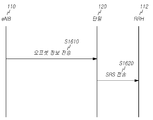
본 발명의 실시예에 따른 상향링크 사운딩 참조신호 전송전력 제어방법에서는 기존 단말들과의 호환을 위해 전술한 바와 같이 전송전력 지정을 위한 오프셋값의 설정시 기존의 전력제어 범위를 포함하면서 확장된 전력제어 범위에서 전력값이 지정되도록 오프셋값을 결정한다. 도 15는 본 발명의 실시예들에 따른 송수신포인트의 상향링크 사운딩 참조신호 전송전력 제어방법의 흐름도이다.In the method for controlling uplink sounding reference signal transmission power according to an embodiment of the present invention, when the offset value for transmission power designation is set as described above for compatibility with existing terminals, the existing power control range is extended. The offset value is determined so that the power value is specified in the power control range. 15 is a flowchart illustrating a method for controlling uplink sounding reference signal transmission power of a transmission / reception point according to embodiments of the present invention.
도 15를 참조하면 본 발명의 일실시예에 따른 송수신포인트의 전송전력 제어방법은, 송수신포인트(110)가 사운딩 참조신호의 전송전력의 제어에 대한 가능한 범위를 늘리도록 단말의 상향링크 사운딩 참조신호의 전송전력의 특정 오프셋값을 설정하는 단계(S1510) 및 송수신포인트가 설정된 오프셋값을 지시하는 오프셋 정보를 상위계층 시그널링, 예를 들어 RRC 시그널링을 통해 단말(120)에 전송하는 단계(S1520)를 포함한다. S1520단계에서 단말(120)은 이 오프셋 정보를 수신한다.Referring to FIG. 15, in a method of controlling transmission power of a transmission / reception point according to an embodiment of the present invention, uplink sounding of a terminal so that the transmission /
사운딩 참조신호의 전력제어에 사용되는 파라미터들 중 사운딩 참조신호의 전송전력의 제어에 대한 가능한 범위를 늘리기 위한 방법들 중 하나로 상향링크 사운딩 참조신호의 전송전력의 오프셋값(P_SRS_OFFSET,c(m), (m= {0, 1}))의 가능한 범위를 증가시킬 수 있다.Among the parameters used for the power control of the sounding reference signal, one of methods for increasing the possible range for the control of the transmission power of the sounding reference signal is an offset value of the transmission power of the uplink sounding reference signal (P_SRS_OFFSET, c ( m), the possible range of (m = {0, 1})) can be increased.
S1510단계에서 송수신포인트(110)는, 제1범위 및 제1범위보다 더 큰 값들을 포함하는 제2범위를 포함하는 전체 범위에서 일정한 간격(step size)으로 단말의 상향링크 사운딩 참조신호의 전송전력의 특정 오프셋값을 설정한다. 이때 상향링크 사운딩 참조신호의 전송전력의 특정 오프셋값은 수학식 7에서 P_SRS_OFFSET,c(m)(m= {0, 1})을 의미한다.In operation S1510, the transmission /
다시 말해 m= 0과 1에 대해서 둘 다 모두 PUSCH 전력제어와 연계(coupling)된 전력제어를 수행하도록 설정하되, 해당 P_SRS_OFFSET,c(m)의 오프셋값에 대한 범위를 증가시킴으로서 송수신포인트는 각각의 의도된 단말의 동작에 맞게 증가시킨 범위 내에서 전송전력이 특정되도록 P_SRS_OFFSET,c(m)의 오프셋값을 지시할 수 있다.In other words, both m = 0 and 1 are configured to perform power control coupled with PUSCH power control, but by increasing the range for the offset value of the corresponding P_SRS_OFFSET, c (m) The offset value of P_SRS_OFFSET, c (m) may be indicated so that the transmission power is specified within a range increased according to the intended operation of the terminal.
오프셋값의 범위를 증가시키는 방법으로, 기존 단말과 기존 네트워크와의 백워드 호환성(backward compatibility)를 위해 본 발명의 실시예들이 적용되는 새로운 단말이 본 발명의 실시예들이 적용되지 않는 기존의 단말과 동일하게 동작할 수 있는 범위, 즉 P_SRS_OFFSET,c(m), (m= {0, 1})의 가능한 범위를 제1범위로 포함할 수 있도록 하면서 새롭게 증가된 범위를 제2범위로 포함하고 이들을 포함하는 P_SRS_OFFSET,c(m), (m= {0, 1})의 전체 범위 내에 설정되는 간격(step size)를 동일하게 유지할 수 있다. 이는 기존 단말과의 호환성을 유지하기 위함이다.As a method of increasing the range of the offset value, the new terminal to which the embodiments of the present invention are applied for backward compatibility between the existing terminal and the existing network is compared with the existing terminal to which the embodiments of the present invention are not applied. Include the newly increased range as the second range and make it possible to include the range that can be operated equally, that is, the possible range of P_SRS_OFFSET, c (m), (m = {0, 1}) as the first range. It is possible to maintain the same step size set within the entire range of P_SRS_OFFSET, c (m) and (m = {0, 1}). This is to maintain compatibility with the existing terminal.
예를 들어 송수신포인트로부터 상위계층 시그널링에 의해 주어지는 변수 Ks에 대해, Ks=1.25일 때 P_SRS_OFFSET,c(m), (m= {0, 1})이 지정하는 전송전력범위의 전체 범위는 [-3, 28]dB 범위로 제1범위는 [-3,12]dB이고 제2범위는 (12,28]dB이고 일정한 간격은 1dB 간격일 수 있다. 제2범위의 경우 12dB에 해당하는 오프셋값은 포함하지 않는바 제2범위에서의 오프셋값은 13, 14, 15..dB일 수 있다. 한편 Ks=0일 때 전체 범위는 [-10.5, 28.5]dB로 제1범위는 [-10.5,12]dB이고, 제2범위는 (12,28.5]dB이고 일정한 간격은 1.5 dB 간격일 수 있다. 이 경우에도 제2범위는 12dB의 경계값을 포함하지 않는바 제2범위에서 오프셋값은 13.5, 15, 16.5 … dB 등에 해당할 수 있다.For example, for the variable Ks given by higher layer signaling from a transmission / reception point, when Ks = 1.25, the entire range of the transmission power range designated by P_SRS_OFFSET, c (m), (m = {0, 1}) is [- 3, 28] dB range, the first range may be [-3, 12] dB, the second range is (12, 28) dB, and the regular interval may be 1 dB interval. The offset value in the second range may be 13, 14, 15..dB, but when Ks = 0, the entire range is [-10.5, 28.5] dB and the first range is [-10.5, 12] dB, the second range is (12,28.5] dB and the constant interval may be 1.5dB intervals, even in this case, the second range does not include a threshold value of 12dB and the offset value in the second range is 13.5. , 15, 16.5… dB, and so on.
결과적으로 Ks=1.25일 때는 1dB 간격(step size)을 가지고 [-3, 12]dB 범위를 포함시키도록 새로운 단말에 대한 P_SRS_OFFSET,c(m), (m= {0, 1})을 지시할 수 있는 범위를 확장하고, Ks=0일 때는 1.5 dB 간격을 가지고 [-10.5, 12]dB 범위를 포함시키도록 새로운 단말에 대한 P_SRS_OFFSET,c(m), (m= {0, 1})을 지시할 수 있는 범위를 확장한다.As a result, when Ks = 1.25, P_SRS_OFFSET, c (m), (m = {0, 1}) for the new UE is indicated to include the range of [-3, 12] dB with a step size of 1 dB. Expand the range, and if Ks = 0, P_SRS_OFFSET, c (m), (m = {0, 1}) for the new terminal to include the range [-10.5, 12] dB with a 1.5 dB interval. Extend the range that can be indicated.
이러한 방법은 본 발명의 실시예들이 적용되는 새로운 단말이 도 7 내지 도 14를 참조하여 설명한 새로운 네트워크에서의 동작 뿐만 아니라 도 2 및 도 3을 참조하여 설명한 기존 네크워크에 속하여 동작할 경우 본 발명의 실시예들이 적용되지 않는 기존 단말의 설정과 동일하게 동작할 수 있도록 설정하고 기존 단말이 새로운 네트워크에 속하여 동작할 경우 기존 네트워크에서 지시되는 해당 오프셋값의 설정과 동일한 값을 지시해줄 수 있도록 만들어 줌으로서 백워드 호환성를 유지할 수 있게 된다.This method is implemented when the new terminal to which the embodiments of the present invention are applied operates not only in the new network described with reference to FIGS. 7 to 14 but also belongs to the existing network described with reference to FIGS. 2 and 3. By setting the examples to operate the same as the configuration of the existing terminal does not apply, and if the existing terminal is operating in a new network, it is possible to indicate the same value as the setting of the corresponding offset value indicated in the existing network. Word compatibility can be maintained.
예를 들어 본 발명의 실시예들이 적용되는 새로운 단말이 도 7 내지 도 14를 참조하여 설명한 새로운 네트워크에서 동작할 경우 송수신포인트는 제1범위와 제2범위를 포함하는 전체 범위 내에서 일정한 간격으로 전송전력을 특정하는 오프셋값을 각 단말에게 설정할 수 있다. 한편, 본 발명의 실시예들이 적용되는 새로운 단말이 도 2 및 도 3을 참조하여 설명한 기존 네크워크에 속하여 동작할 경우 송수신포인트는 제1범위 내에서 일정한 간격으로 전송전력을 지정하는 오프셋값을 각 단말에 설정할 수 있다. 또한, 본 발명의 실시예들이 적용되지 않는 기존 단말이 새로운 네크워크에서 동작할 경우 기존 네트워크에서 지시되는 해당 오프셋값의 설정과 동일한 값, 다시 말해 제1범위 내에서 일정한 간격의 특정 오프셋값을 각 단말에 설정할 수 있다.For example, when a new terminal to which the embodiments of the present invention are applied operates in the new network described with reference to FIGS. 7 to 14, transmission and reception points are transmitted at regular intervals within the entire range including the first range and the second range. An offset value specifying power can be set for each terminal. Meanwhile, when a new terminal to which embodiments of the present invention are applied operates in the existing network described with reference to FIGS. 2 and 3, the transmission / reception point has an offset value for designating transmission power at regular intervals within a first range. Can be set on In addition, when the existing terminal to which the embodiments of the present invention are not applied operates in a new network, each terminal receives a specific offset value of a predetermined interval within the first range, that is, the same value as that of the corresponding offset value indicated in the existing network. Can be set on
전술한 바와 같이 사운딩 참조신호는 주기적 및 비주기적 사운딩 참조신호 중 하나 이상일 수 있다. 따라서 송수신포인트(110)는 필요에 따라 오프셋 정보를 결정하는 단계(S1510)에서 주기적 사운딩 참조신호와 비주기적 사운딩 참조신호에 대해 독립적으로 오프셋값을 설정할 수 있다. 즉 P_SRS_OFFSET,c(m)의 m값 (m=0,1)에 따라 별도의 오프셋값을 설정할 수 있다.As described above, the sounding reference signal may be one or more of periodic and aperiodic sounding reference signals. Accordingly, the transmission /
사운딩 참조신호의 전력제어에 사용되는 파라미터들 중 사운딩 참조신호의 전송전력의 제어에 대한 가능한 범위를 늘리기 위한 방법들 중 다른 하나로 상향링크 사운딩 참조신호의 전송전력의 오프셋값(P_SRS_OFFSET,c(m))의 m의 개수를 증가시킬 수 있다. The offset value of the transmit power of the uplink sounding reference signal is another one of methods for increasing the possible range for the control of the transmit power of the sounding reference signal among the parameters used for power control of the sounding reference signal (P_SRS_OFFSET, c (m)) may increase the number of m.
P_SRS_OFFSET,c(m)의 m의 개수를 증가시키는 방법으로, S1510단계에서, 송수신포인트는 P_SRS_OFFSET,c(m)에서 m=0 및 m=1 뿐만 아니라 m≥2으로 설정할 수 있다. As a method of increasing the number of m of P_SRS_OFFSET, c (m), in step S1510, the transmission / reception point may be set to m≥2 as well as m = 0 and m = 1 in P_SRS_OFFSET, c (m).
다시 말해 송수신포인트는 기존과 동일하게 m=0에 대해서 주기적 사운딩 참조신호를 위한 전력제어의 전력 오프셋 파라미터(P_SRS_OFFSET,c(0))로 사용하고 m=1에 대해서 비주기적 사운딩 참조신호를 위한 전력제어의 전력 오프셋 파라미터(P_SRS_OFFSET, c(1))로 사용하도록 설정하며, 추가적인 m≥2 (예를 들어 m=2, 3 또는 4)값에 대해서 주기적 혹은 비주기적 사운딩 참조신호를 위한 전력 제어의 설정 시에 PUSCH 전력 제어와 해제(decoupling)되도록 설정되는 경우 해당 m값에 따른 P_SRS_OFFSET,c(m)의 가능한 범위 내에서의 특정 단말에 특정 전력 오프셋 파라미터(P_SRS_OFFSET,c(m), m≥2)로 설정할 수 있다.In other words, the transmit / receive point is used as the power offset parameter (P_SRS_OFFSET, c (0)) of the power control for the periodic sounding reference signal with respect to m = 0 and the aperiodic sounding reference signal with respect to m = 1. Power offset parameter (P_SRS_OFFSET, c (1)) of the power control for the control, for periodic or aperiodic sounding reference signals for additional m≥2 (eg m = 2, 3 or 4). When the power control is set to decoupling with PUSCH power control, the specific power offset parameter (P_SRS_OFFSET, c (m),) to a specific terminal within a possible range of P_SRS_OFFSET, c (m) according to the corresponding m value. m ≥ 2).
사운딩 참조신호의 전력제어에 사용되는 파라미터들 중 사운딩 참조신호의 전송전력의 제어에 대한 가능한 범위를 늘리기 위한 방법들 중 또 다른 하나로 송수신포인트는 상향링크 사운딩 참조신호의 전송전력의 오프셋값(P_SRS_OFFSET,c(m))의 m의 개수도 늘리고 그 오프셋값이 특정할 수 있는 전송전력의 범위도 증가시킬 수 있다.Among the parameters used to control the power of the sounding reference signal, one of the methods for increasing the possible range for the control of the transmission power of the sounding reference signal is an offset value of the transmit power of the uplink sounding reference signal. The number of m of (P_SRS_OFFSET, c (m)) can also be increased and the range of transmission power whose offset value can be specified can also be increased.
다시 말해 m= 0과 1에 대해서는 둘 다 모두 PUSCH 전력제어와 연계된 전력제어를 수행하도록 설정하되 해당 P_SRS_OFFSET,c(m)에 대한 범위를 증가시킴으로서 송수신포인트가 각각의 의도된 단말의 동작에 맞게 지시할 수 있도록 설정할 수 있다. 한편, 송수신포인트는 기존과 동일하게 m=0에 대해서 주기적 사운딩 참조신호를 위한 전력제어의 전력 오프셋 파라미터(P_SRS_OFFSET,c(0))로 사용하고 m=1에 대해서 비주기적 사운딩 참조신호를 위한 전력제어의 전력 오프셋 파라미터(P_SRS_OFFSET,c(1))로 사용하도록 설정하며, 추가적인 m≥2 (예를 들어 m=2, 3 또는 4)값에 대해서 주기적 혹은 비주기적 사운딩 참조신호를 위한 전력 제어의 설정 시에 PUSCH 전력 제어와 해제(decoupling)되도록 설정되는 경우 해당 m값에 따른 P_SRS_OFFSET,c(m)의 가능한 범위 내에서의 특정 단말에 특정 전력 오프셋 파라미터(P_SRS_OFFSET,c(m), m≥2)로 설정할 수 있다. In other words, both m = 0 and 1 are configured to perform power control associated with PUSCH power control, but increase the range for the corresponding P_SRS_OFFSET, c (m) so that the transmit / receive point is adapted to the operation of each intended terminal. Can be set to indicate. Meanwhile, the transmit / receive point is used as the power offset parameter (P_SRS_OFFSET, c (0)) of the power control for the periodic sounding reference signal for m = 0 and the non-periodic sounding reference signal for m = 1. Power offset parameter (P_SRS_OFFSET, c (1)) of the power control for the control, for periodic or aperiodic sounding reference signals for additional m≥2 (e.g., m = 2, 3 or 4). When the power control is set to decoupling with PUSCH power control, the specific power offset parameter (P_SRS_OFFSET, c (m),) to a specific terminal within a possible range of P_SRS_OFFSET, c (m) according to the corresponding m value. m ≥ 2).
여기서 추가적인 m≥2를 적용하는 사운딩 참조신호에 대해서는 주기적 사운딩 참조신호는 고려하지 않고 비주기적 사운딩 참조신호에 대한 전력 제어 설정에 사용하거나, 비주기적 참조신호는 고려하지 않고 주기적 참조신호에 대한 전력 제어 설정에 사용할 수 있다.In this case, for a sounding reference signal to which an additional m≥2 is applied, it is used to set the power control for the aperiodic sounding reference signal without considering the periodic sounding reference signal or to the periodic reference signal without considering the aperiodic reference signal. Can be used for power control settings.
S1520단계에서, 송수신포인트는 설정된 오프셋값을 지시하는 오프셋 정보를 시간-주파수 자원을 통해 단말에 전송한다. In step S1520, the transmission and reception point transmits the offset information indicating the set offset value to the terminal through the time-frequency resources.
송수신포인트는 오프셋 정보를 상위계층 시그널링, 예를 들어 RRC 메시지를 통해 단말에 전송할 수 있다. The transmission / reception point may transmit the offset information to the terminal through higher layer signaling, for example, an RRC message.
오프셋 정보는 제1범위를 일정한 간격으로 표현한 제1파라미터와 제2범위를 일정한 간격으로 표현한 제2파라미터를 포함할 수 있다. 제1파라미터는 Ks=1.25일 때 [-3,12]dB의 제1범위를 1dB 간격으로 표현하고 Ks=0일 때 [-10.5,12]dB의 제1범위를 1.5dB 간격으로 표현하므로 총 4비트(0000 내지 1111)일 수 있다. 제2파라미터는 Ks=1.25일 때 (12,28]dB의 제2범위를 1dB 간격으로 표현하고 Ks=0일 때 (12,28.5]dB의 제2범위를 1.5dB 간격으로 표현할 수 있다. 이 때 제2파라미터는 제1범위 및 제2범위를 포함하는 전체범위를 모두 표현할 수 있도록 총 5비트(00000 내지 11111)크기의 파라미터일 수 있으나, 실질적으로는 제2범위를 표현하기 위해 5비트의 값들 중 제2범위에 대응되는 10000내지 11111의 값들만 사용할 수 있다.The offset information may include a first parameter representing the first range at regular intervals and a second parameter representing the second range at regular intervals. The first parameter represents the first range of [-3,12] dB in 1 dB interval when Ks = 1.25, and the first range of [-10.5,12] dB in 1.5 dB interval when Ks = 0. 4 bits (0000 to 1111). The second parameter may represent the second range of (12,28) dB at 1 dB interval when Ks = 1.25, and the second range of (12,28.5] dB at 1.5 dB interval when Ks = 0. In this case, the second parameter may be a parameter of a total size of 5 bits (00000 to 11111) so as to represent both the first range and the entire range including the second range, but substantially 5 bits to express the second range. Only values of 10000 to 11111 corresponding to the second range of values may be used.
송수신포인트는 기존의 단말 또는 기존의 네트워크에서 동작하는 단말에 제1파라미터만을 포함하는 오프셋 정보를 전송하고 새로운 단말 또는 새로운 네트워크에서 동작하는 단말에 제1파라미터 혹은 제 2 파라미터중 적어도 하나를 포함하는 오프셋 정보를 전송할 수 있다.The transmission / reception point transmits offset information including only the first parameter to an existing terminal or a terminal operating in an existing network and an offset including at least one of the first parameter or the second parameter to a new terminal or a terminal operating in a new network. Information can be sent.
송수신포인트(110)는 제1파라미터와 제2파라미터를 포함하는 오프셋 정보를 단말(120)에 전송할 수 있다. The transmission /
S1510단계에서, 송수신포인트는 P_SRS_OFFSET,c(m)에서 m=0 및 m=1 뿐만 아니라 m≥2으로 설정한 경우 오프셋 정보는 m의 값을 지시하는 정보를 포함할 수 있다. 예를 들어 m=0, 1, 2, 3, 4, 5인 경우 오프셋 정보는 m의 값을 지시하는 특정 비트, 예를 들어 3비트를 포함할 수 있으나 이에 제한되지 않는다.도 16은 본 발명의 다른 실시예에 따른 단말의 상향링크 사운딩 참조신호의 전송전력 제어방법의 흐름도이다.In step S1510, when the transmission and reception point is set to m≥2 as well as m = 0 and m = 1 in P_SRS_OFFSET, c (m), the offset information may include information indicating the value of m. For example, when m = 0, 1, 2, 3, 4, and 5, the offset information may include a specific bit indicating a value of m, for example, 3 bits, but is not limited thereto. A flowchart of a method of controlling a transmit power of an uplink sounding reference signal of a terminal according to another embodiment of the present invention.
도 16을 참조하면 본 발명의 다른 실시예에 따른 단말(120)의 상향링크 사운딩 참조신호의 전송전력 제어방법은, 단말(120)이 사운딩 참조신호의 전송전력의 제어에 대한 가능한 범위를 늘리도록 송수신포인트(110)에 의해 설정된 단말(120)의 상향링크 사운딩 참조신호의 전송전력의 특정 오프셋값을 지시하는 오프셋 정보를 시간-주파수 자원을 통해 전술한 송수신포인트(110)로부터 수신하는 단계(S1610) 및 오프셋 정보가 지시하는 특정 오프셋값을 사용한 상향링크 사운딩 참조신호의 전송전력으로 상향링크 사운딩 참조신호를 전송하는 단계(S1620)를 포함한다.Referring to FIG. 16, in the method of controlling transmission power of an uplink sounding reference signal of a terminal 120 according to another embodiment of the present invention, the terminal 120 may determine a range for controlling transmission power of a sounding reference signal. Receiving the offset information indicating the specific offset value of the transmission power of the uplink sounding reference signal of the terminal 120 set by the transmission and
S1610단계에서 단말은 송수신포인트에 의해 설정된 오프셋값을 지시하는 오프셋 정보를 시간-주파수 자원을 통해 수신한다. 단말은 오프셋 정보를 상위계층 시그널링, 예를 들어 RRC 메시지를 통해 송수신포인트로부터 수신할 수 있다. In step S1610, the terminal receives the offset information indicating the offset value set by the transmission and reception point through the time-frequency resources. The terminal may receive the offset information from the transmission and reception point through higher layer signaling, for example, an RRC message.
도 16의 S1620 단계에서 사운딩 참조신호의 수신대상은 도 16에서 도시한 바와 같이 서빙 송수신포인트(110)가 아닌 전술한 바와 같이 사운딩 참조신호의 시퀀스 생성을 위한 참조신호 아이디에 따라 다른 송수신포인트(112)가 될 수도 있지만 서빙 송수신 포인트(110)가 될 수도 있다.In operation S1620 of FIG. 16, the receiving target of the sounding reference signal is different from the serving transmitting /
도 17은 본 발명의 실시예에 따른 사운딩 참조신호 전송전력 제어방법으로 사운딩 참조신호가 서빙 송수신 포인트로 전송되는 예를 도시한 도면이다.17 is a diagram illustrating an example in which a sounding reference signal is transmitted to a serving transmission / reception point in a sounding reference signal transmission power control method according to an embodiment of the present invention.
도 17을 참조하면 본 발명의 다른 실시예에 따른 단말(120)의 상향링크 사운딩 참조신호의 전송전력 제어방법은, 단말(120)이 사운딩 참조신호의 전송전력의 제어에 대한 가능한 범위를 늘리도록 송수신포인트(110)에 의해 설정된 단말(120)의 상향링크 사운딩 참조신호의 전송전력의 특정 오프셋값을 지시하는 오프셋 정보를 시간-주파수 자원을 통해 전술한 송수신포인트(110)로부터 수신하는 단계(S1710) 및 오프셋 정보가 지시하는 특정 오프셋값을 사용한 상향링크 사운딩 참조신호의 전송전력으로 상향링크 사운딩 참조신호를 전송하는 단계(S1720) 그리고 상향링크 데이터 채널의 전송은 RRH(112)로 전송하는 단계(S1730)를 포함한다.Referring to FIG. 17, in the method of controlling transmission power of an uplink sounding reference signal of a terminal 120 according to another embodiment of the present invention, the terminal 120 may determine a range for controlling transmission power of a sounding reference signal. Receiving the offset information indicating the specific offset value of the transmission power of the uplink sounding reference signal of the terminal 120 set by the transmission and
S1710단계에서 단말은 송수신포인트에 의해 설정된 오프셋값을 지시하는 오프셋 정보를 시간-주파수 자원을 통해 수신한다. 단말은 오프셋 정보를 상위계층 시그널링, 예를 들어 RRC 메시지를 통해 송수신포인트로부터 수신할 수 있다.In step S1710, the terminal receives the offset information indicating the offset value set by the transmission and reception points through the time-frequency resources. The terminal may receive the offset information from the transmission and reception point through higher layer signaling, for example, an RRC message.
전술한 바와 같이 오프셋 정보는 제1범위를 일정한 간격으로 표현한 제1파라미터와 제2범위를 일정한 간격으로 표현한 제2파라미터를 포함할 수 있다. 제1파라미터는 Ks=1.25일 때 [-3,12]dB의 제1범위를 1dB 간격으로 표현하고 Ks=0일 때 [-10.5,12]dB의 제1범위를 1.5dB 간격으로 표현하므로 총 4비트(0000 내지 1111)일 수 있다. 제2파라미터는 Ks=1.25일 때 (12,28]dB의 제2범위를 1dB 간격으로 표현하고 Ks=0일 때 (12,28.5]dB의 제2범위를 1.5dB 간격으로 표현할 수 있다. 이 때 제2파라미터는 제1범위 및 제2범위를 포함하는 전체범위를 모두 표현할 수 있도록 총 5비트(00000 내지 11111)크기의 파라미터일 수 있으나, 실질적으로는 제2범위를 표현하기 위해 5비트의 값들 중 제2범위에 대응되는 10000내지 11111의 값들만 사용할 수 있다.As described above, the offset information may include a first parameter representing the first range at regular intervals and a second parameter representing the second range at regular intervals. The first parameter represents the first range of [-3,12] dB in 1 dB interval when Ks = 1.25, and the first range of [-10.5,12] dB in 1.5 dB interval when Ks = 0. 4 bits (0000 to 1111). The second parameter may represent the second range of (12,28) dB at 1 dB interval when Ks = 1.25, and the second range of (12,28.5] dB at 1.5 dB interval when Ks = 0. In this case, the second parameter may be a parameter of a total size of 5 bits (00000 to 11111) so as to represent both the first range and the entire range including the second range, but substantially 5 bits to express the second range. Only values of 10000 to 11111 corresponding to the second range of values may be used.
송수신포인트가 P_SRS_OFFSET,c(m)에서 m=0 및 m=1 뿐만 아니라 m≥2으로 설정한 경우, 오프셋 정보는 m의 값을 지시하는 정보를 포함할 수 있다. 예를 들어 m=0, 1, 2, 3, 4, 5인 경우 오프셋 정보는 m의 값을 지시하는 3비트를 포함할 수 있으나 이에 제한되지 않는다.When the transmission / reception point is set to m≥2 as well as m = 0 and m = 1 in P_SRS_OFFSET, c (m), the offset information may include information indicating a value of m. For example, when m = 0, 1, 2, 3, 4, and 5, the offset information may include 3 bits indicating the value of m, but is not limited thereto.
S1620단계에서, 단말은 오프셋 정보가 지시하는 특정 오프셋값에 사용한 상향링크 사운딩 참조신호의 전송전력으로 상향링크 사운딩 참조신호를 전송한다. In step S1620, the terminal transmits the uplink sounding reference signal with the transmission power of the uplink sounding reference signal used for the specific offset value indicated by the offset information.
단말은 오프셋 정보가 지시하는 특정 오프셋값을 사용하여 수학식 7에 의해 주어지는 서브프레임(i)에서 전송되는 단말의 사운딩 참조신호의 전송전력( ![]()
![]()
Ks=1.25일 때 수학식 7에서 오프셋값 P_SRS_OFFSET,c(m)은 제1파라미터에 의해 지시하는 [-3,12]dB의 제1범위와 제2파라미터에 의해 지시하는 (12,28]dB의 제2범위를 포함하는 전체 범위에서 1dB 간격으로 표현한 값일 수 있다. 또한 Ks=0일 때 수학식 7에서 오프셋값 P_SRS_OFFSET,c(m)은 제1파라미터에 의해 지시하는 [-10.5,12]dB의 제1범위와, 제2파라미터에 의해 지시하는 (12,28.5]dB의 제2범위를 포함하는 전체 범위에서 1.5dB 간격으로 표현한 값일 수 있다.When Ks = 1.25, the offset value P_SRS_OFFSET, c (m) in Equation 7 is (12,28) dB indicated by the first range of [-3,12] dB indicated by the first parameter and by the second parameter. The offset value P_SRS_OFFSET, c (m) in Equation 7 when Ks = 0 is represented by the first parameter [-10.5,12]. It may be a value expressed in 1.5 dB intervals over the entire range including the first range of dB and the second range of (12,28.5) dB indicated by the second parameter.
전술한 바와 같이 본 발명의 실시예에 따른 사운딩 참조신호 전송방법에서는 오프셋값이 지정할 수 있는 전송전력 범위를 증가시키는 것 이외에 수학식 7에서 경로손실 추정값인 PLc 를 CSI-RS를 이용하여 추정된 경로손실을 추정할 수도 있고, 하향링크에서 사용하는 CRS(cell specific RS)와 CSI-RS를 모두 이용하여 경로손실을 추정할 수도 있다.As described above, in the sounding reference signal transmission method according to the embodiment of the present invention, in addition to increasing the transmission power range that the offset value can specify, the estimation of the path loss PL c in Equation 7 is estimated using CSI-RS. The estimated path loss may be estimated, or the path loss may be estimated using both the cell specific RS (CRS) and the CSI-RS used in the downlink.
우선 하향링크에서 사용되는 CSI-RS를 이용하여 경로손실을 추정할 수 있다.First, the path loss can be estimated using the CSI-RS used in the downlink.
일 예로 단말-특정하게 정해지는 논-제로 파워 CSI-RS 자원(non-zero power CSI-RS resource)과 제로 파워 CSI-RS 자원(zero-power CSI-RS resource)을 이용하여 상향링크 채널 및 신호 전송을 위한 전력제어 파라미터로서 해당 경로손실을 추정할 수 있다. 즉 논-제로 파워 CSI-RS 자원에 대해서는 해당 단말의 PDCCH 또는 PDSCH를 수신하는 하향링크에 대한 경로손실 추정을 위해 사용하고, 제로 파워 CSI-RS 자원에 대해서는 PDCCH 또는 PDSCH를 수신하는 하향링크의 경로 손실(path-loss) 추정을 위함이 아닌 어떤 특정 CoMP 측정 셋(CoMP measurement set) 내에서의 경로손실 추정으로 고려하여 단말이 상향링크로 전송하는 물리적 채널 및 신호의 전송전력 제어시 타켓 수신 송수신포인트에 맞게 해당 경로손실 추정값을 사용할 수 있도록 할 수 있다.For example, an uplink channel and a signal using a UE-specific non-zero power CSI-RS resource and a zero-power CSI-RS resource. The path loss can be estimated as a power control parameter for transmission. That is, a non-zero power CSI-RS resource is used to estimate a path loss for a downlink receiving a PDCCH or PDSCH of a corresponding UE, and a downlink path for receiving a PDCCH or PDSCH for a zero power CSI-RS resource is used. Target receiving transmission / reception points when controlling transmission power of physical channels and signals transmitted by the UE in consideration of path loss estimation within a specific CoMP measurement set, not for path-loss estimation. The path loss estimate can be used accordingly.
다른 예로 하향링크에서 단말-특정하게 전송되는 CSI-RS 자원들 중 간섭 신호측정 자원들(interference measurement resources(IMRs))을 이용하여 경로손실을 추정할 수 있다. 이 경우 PDCCH 또는 PDSCH를 수신하는 하향링크의 경로손실 추정을 위함이 아닌 어떤 특정 CoMP 측정 셋 내에서의 경로손실 추정을 고려하여 단말(120)이 상향링크로 전송하는 물리적 채널 및 신호의 전송전력 제어시 타켓 수신 송수신포인트에 맞게 해당 경로손실 추정값을 사용하도록 할 수 있다.As another example, path loss may be estimated using interference measurement resources (IMRs) among CSI-RS resources transmitted in a downlink. In this case, the transmission power control of the physical channel and the signal transmitted by the terminal 120 in the uplink in consideration of the path loss estimation in a specific CoMP measurement set, rather than the estimation of the path loss of the downlink receiving the PDCCH or PDSCH. The path loss estimation value can be used according to the target receiving transmission / reception point.
전술한 바와 같이 하향링크에서 사용하는 CRS(cell specific RS)와 CSI-RS를 모두 이용하여 경로손실을 추정할 수도 있다.As described above, the path loss may be estimated using both the cell specific RS and the CSI-RS used in the downlink.
일 예로 셀-특정하게 정해지는 셀-특정 참조신호를 이용하여 단말(120)은 PDCCH 또는 PDSCH를 수신하는 하향링크에 대한 경로손실 추정을 수행하고, 단말-특정하게 정해지는 제로 파워 CSI-RS 자원 또는 논-제로 파워 CSI-RS 자원에 대해서는 PDCCH 또는 PDSCH를 수신하는 하향링크에 대한 경로손실 추정이 아닌 다른 송수신포인트로의 경로손실 추정값으로 고려하여 단말(120)이 상향링크로 전송하는 물리적 채널 및 신호의 전송전력 제어시 타켓 수신 송수신포인트에 맞게 해당 값을 사용할 수 있도록 할 수 있다. 여기서 다른 송수신포인트로의 경로손실 추정값으로 사용되는 CSI-RS 자원은 제로 파워 CSI-RS 자원이거나 논-제로 파워 CSI-RS 자원일 수 있다.For example, the
다른 예로 셀-특정하게 정해지는 셀-특정 RS(cell-specific Reference Signal)를 이용하여 단말(120)은 PDCCH 또는 PDSCH를 수신하는 하향링크에 대한 경로손실 추정을 수행하고, 논-제로 파워 CSI-RS 자원에 대해서는 CRS를 통한 경로손실 추정을 보정하기 위해 사용하도록 하고, 제로 파워 CSI-RS 자원에 대해서는 PDCCH 또는 PDSCH를 수신하는 하향링크의 경로손실 추정을 위함이 아닌 어떤 특정 CoMP 측정 셋 내에서의 경로손실 추정을 고려하여 단말(120)이 상향링크로 전송하는 채널 및 신호의 전송전력 제어시 타켓 수신 송수신포인트에 맞게 해당 경로손실 추정값을 사용할 수 있다.As another example, using a cell-specific cell-specific reference signal (RS), the terminal 120 performs path loss estimation for a downlink receiving a PDCCH or a PDSCH, and uses a non-zero power CSI-. RS resources are used to calibrate the path loss estimates through CRS, and zero power CSI-RS resources are used within certain specific CoMP measurement sets, not for downlink path loss estimates receiving PDCCH or PDSCH. In consideration of the path loss estimation, the terminal 120 may use the corresponding path loss estimation value according to the target receiving transmission / reception point when controlling the transmission power of the channel and the signal transmitted by the uplink.
또 다른 예로 셀-특정하게 정해지는 셀-특정 참조신호(Reference Signal)를 이용하여 단말(120)은 PDCCH 또는 PDSCH를 수신하는 하향링크에 대한 경로손실 추정을 수행하고, 논-제로 파워 CSI-RS 자원에 대해서는 CRS를 통한 경로손실 추정을 보정하기 위해 사용하며, 단말-특정하게 전송되는 CSI-RS 자원 중 간섭신호 측정 자원(interference measurement resource(IMR))을 이용하여 경로손실을 추정하도록 할 수 있다. 이 경우 PDCCH 또는 PDSCH를 수신하는 하향링크의 경로손실 추정을 위함이 아닌 어떤 특정 CoMP 측정 셋 내에서의 경로손실 추정을 고려하여 단말(120)이 상향링크로 전송하는 채널 및 신호의 전송전력 제어시 타켓 수신대상 송수신포인트에 맞게 해당 경로손실 추정값을 사용할 수 있다.As another example, using a cell-specific cell-specific reference signal, the terminal 120 performs path loss estimation for a downlink receiving a PDCCH or a PDSCH, and uses a non-zero power CSI-RS. The resource may be used to correct the path loss estimation through the CRS, and the path loss may be estimated by using an interference measurement resource (IMR) among the UE-specifically transmitted CSI-RS resources. . In this case, when controlling the transmission power of the channel and the signal transmitted by the
전술한 바와 같이 하향링크에서 사용하는 CRS(cell specific RS)와 CSI-RS를 모두 이용하여 경로손실을 추정하는 방법은 상/하향링크를 동일한 송수신포인트로 전송을 수행하고 있는 기존 단말의 전송전력 제어에 대해서는 영향을 주지 않도록 설정하고, 기존 단말이 아닌 새로운 설정을 수용할 수 있는 단말에 대해서만 추가적인 CSI-RS 자원을 통한 경로손실 추정을 수행하도록 할 수 있다.As described above, a method for estimating path loss using both CRS (cell specific RS) and CSI-RS used in the downlink is to control the transmission power of the existing terminal transmitting the uplink / downlink to the same transmission / reception point. In this case, the path loss estimation may be performed through additional CSI-RS resources only for the terminal that can accommodate the new configuration and not the existing terminal.
이상 기존 단말 및 기존 네트워크의 시스템과의 호환성을 유지하면서 사운딩 참조신호의 전송전력 제어범위를 효율적으로 확장하고 경로손실에 대한 추정값을 수정하는 방법에 대하여 설명하였다.The method of efficiently extending the transmission power control range of the sounding reference signal and modifying the estimated value for the path loss while maintaining compatibility with the system of the existing terminal and the existing network has been described above.
전술한 바와 같이 본 발명의 실시예가 적용되는 무선통신시스템에서 사운딩 참조신호의 수신대상은 단말에 하향링크 전송하는 서빙 송수신포인트(110)가 될 수도 있지만 경우에 따라서 다른 송수신포인트(112)가 될 수도 있다. 이하에서는 이렇게 사운딩 참조신호의 수신대상이 변경됨에 따라 전술한 확장된 사운딩 참조신호 전송전력 제어범위에서 효율적으로 사운딩 참조신호의 전송전력을 결정하기 위해 사운딩 참조신호의 타겟 수신대상이 서빙 송수신 포인트(110)인 경우와 그렇지 않은 경우를 구분하여 사운딩 참조신호의 전송전력을 제어하는 방법에 관하여 설명하겠다.As described above, in the wireless communication system to which the embodiment of the present invention is applied, the receiving target of the sounding reference signal may be a serving transmission /
본 발명의 실시예에 따른 시스템에서 상향링크 사운딩 참조신호의 전송전력이 제어될 때 도 2 및 도 3을 참조하여 설명한 바와 같이 단말(120)에 하향링크를 전송하는 서빙 송수신포인트(110)으로 사운딩 참조신호가 전송되는 경우와, 도 7 내지 도 14를 참조하여 설명한 바와 같이 사운딩 참조신호의 타겟 수신대상이 다른 송수신포인트(112)로 설정되는 경우를 구분하여 사운딩 참조신호의 전송전력이 설정될 수 있다.When the transmission power of the uplink sounding reference signal is controlled in the system according to an embodiment of the present invention, as described with reference to FIGS. 2 and 3, the serving transmission /
사운딩 참조신호에 대한 전송전력을 설정할 때, 사운딩 참조신호를 수신하는 타겟 수신 송수신포인트가 PUSCH를 전송하는 송수신포인트와 동일한 송수신포인트인지 PUSCH를 전송하는 송수신포인트와 다른 송수신포인트로의 전송인지를 명시적으로 지시할 수 있다.When setting the transmit power for the sounding reference signal, whether the target receiving transmit / receive point receiving the sounding reference signal is the same transmit / receive point or transmit point that transmits the PUSCH or the transmit / receive point that transmits the PUSCH. Can be explicitly indicated.
우선 단말(120)에서 사운딩 참조신호를 전송 시, 송수신포인트(110)가 단말(120)에게 단말(120)이 전송하는 사운딩 참조신호의 수신대상을 향한 사운딩 전송전력을 준정적(semi-static)으로 결정할 수 있도록 명시적인 시그널링으로서 RRC 파라미터에 사운딩 참조신호의 수신대상이 서빙 송수신포인트(110)인지 여부에 관한 특정 비트정보, 예를 들어 1 비트정보를 정의할 수 있다. 또한 송수신포인트(110)가 단말(120)에게 단말(120)이 전송하는 사운딩 참조신호의 전송전력을 동적으로 정할 수 있도록 PDCCH에 추가적인 시그널링으로 사운딩 참조신호의 타켓 수신대상이 서빙 송수신포인트(110)인지 여부에 대한 지시정보를 추가할 수 있다.First, when the terminal 120 transmits the sounding reference signal, the transmission /
단말(120)은 이러한 명시적인 시그널링으로부터 사운딩 참조신호 전송전력을 설정할 때, PUSCH의 전송전력 제어정보와 연계된 파라미터와 서빙 송수신포인트(110)로부터의 경로손실(Path-loss) 추정값에 의해 사운딩 참조신호의 전송전력을 설정할 것인지, 서빙 송수신포인트(110)로의 전송이 아닌 다른 송수신포인트로의 전송임을 단말(120)이 인지하고 해당 다른 송수신포인트로 사운딩 참조신호를 전송하도록 사운딩 참조신호에 대한 전송전력을 PUSCH 전송전력 제어정보와 연계하지 않고 PUSCH와 해제(decoupling)되도록 설정하고, PUSCH 전송전력 제어정보와 연계된 파라미터들 또는 서빙 송수신포인트(110)로부터의 경로손실 추정값에 대해서는 해당 사운딩 참조신호의 전송전력에 대한 설정 시 사용하지 않고 추가적인 사운딩 참조신호에 대한 전송전력 제어방법을 따르도록 설정할 것인지를 정할 수 있다. When the terminal 120 sets the sounding reference signal transmission power from such explicit signaling, the terminal 120 may sound by the parameter associated with the transmission power control information of the PUSCH and the path loss estimate from the serving transmission /
예를 들어 후자의 경우 사운딩 참조신호에 대한 전송전력을 PUSCH 전송전력 제어정보와 연계하지 않고 별도로 설정하기 위해 전술한 바와 같이 확장된 범위, 즉 P_SRS_OFFSET,c(m) 결정시 주어진 m값에 대하여 제1범위와 확장된 제 2 범위를 포함하는 전체 범위에서 사운딩 참조신호 전송전력을 결정되거나 m=0,1이 아닌 추가적인 m값(예를 들어 m=2,3,4…)에 대한 사운딩 참조신호 전송전력 제어범위에서 사운딩 참조신호 전송전력이 설정되도록 오프셋 정보를 결정할 수 있다. 또한 전술한 바와 같이 단말-특정의 CSI-RS 및 셀-특정 RS인 CRS 중 하나 이상을 사용하여 수정된 경로손실 추정값을 반영하여 사운딩 참조신호 전송전력을 결정할 수 있다.For example, in the latter case, in order to separately set the transmission power for the sounding reference signal without being associated with the PUSCH transmission power control information, for the m value determined when the extended range, ie, P_SRS_OFFSET, c (m), is determined as described above. The sounding reference signal transmission power is determined over the entire range including the first range and the extended second range, or the sound for additional m values (e.g. m = 2,3,4…) that is not m = 0,1. The offset information may be determined such that the sounding reference signal transmission power is set in the ding reference signal transmission power control range. In addition, as described above, the sounding reference signal transmission power may be determined by reflecting the modified path loss estimate using one or more of the UE-specific CSI-RS and the cell-specific RS CRS.
이 경우 명시적인 시그널링에 대한 지시정보가 추가적으로 없을 경우에는 단말(120)은 PDCCH를 수신한 서빙 송수신포인트(110)로의 전송임을 인지하고 사운딩 참조신호를 전송함에 있어서 SRS 전송전력 제어에 대한 설정은 PUSCH의 전송전력 제어와 연계된 파라미터를 이용하여 결정될 수 있다. 즉 이 경우 기존의 제 1 범위 안에서의 오프셋값 지정이 이루어질 수 있으며 경로손실에 대한 추정값도 서빙 송수신포인트(110)에 대한 경로손실 추정값을 그대로 따를 수 있다. 이는 사운딩 참조신호와 다른 상향링크 데이터 채널(PUSCH)와 상향링크 컨트롤 채널(PUCCH, PRACH)과의 동시전송의 경우에 대해서 기존의 방식대로 동작하는 단말들과의 호환성을 유지하기 위함이다.In this case, when there is no additional indication information on the explicit signaling, the terminal 120 recognizes that the transmission is to the serving transmission /
전술한 바와 같이 사운딩 참조신호의 수신대상이 서빙 송수신포인트(110)인지 여부에 관하여 명시적으로 시그널링 하지 않고 묵시적(implicit)으로 지시(indication)할 수도 있다.As described above, the reception of the sounding reference signal may be implicitly performed without explicitly signaling whether the receiving target is the serving transmission /
일 예로 명시적인 시그널링에서 RRC 파라미터에 단말(120)에서의 전력제어 동작을 지시하기 위한 추가적인 RRC 파라미터의 오버헤드(overhead) 또는 해당 동작의 구분을 위한 PDCCH에서의 시그널링을 위한 추가적인 오버헤드(overhead) 없이 RRC 파라미터에 사운딩 참조신호의 베이스 시퀀스(base sequence) 생성을 위한 독립적인 
다른 예로 DCI 포맷 0를 통한 비주기적 참조신호 전송의 트리거링과 유사하게 DCI 포맷 1a/2b/2c를 통한 비주기적 참조신호 전송의 트리거링이 수행되는 경우에도 해당 비주기적 사운딩 참조신호 전송을 위한 전력제어 수행 시 독립적인 
또 다른 예로, DCI 포맷 4를 통한 비주기적 참조신호 전송의 트리거링이 수행되는 경우, 해당 비주기적 사운딩 참조신호 전송을 위한 전송전력 제어 수행 시 비주기적 사운딩 참조신호를 위해 사용되는 PDCCH의 2비트 지시정보를 통한 비주기적 사운딩 참조신호의 RRC 파라미터 설정 내에 사운딩 참조신호의 베이스 시퀀스 생성을 위한 독립적인 
이상에서 독립적인 


또한 만약 사운딩 참조신호의 베이스 시퀀스 생성을 위한 독립적인 

![]()
![]()
이는 비주기적 사운딩 참조신호와 다른 상향링크 데이터 채널(PUSCH)와 상향링크 컨트롤 채널(PUCCH, PRACH)과의 동시전송의 경우에 대해서 기존 단말의 동작방식을 유지하도록 하여 종래 시스템과의 호환성을 유지하도록 하기 위함이다.This maintains the operation of the existing terminal in the case of simultaneous transmission between the aperiodic sounding reference signal and another uplink data channel (PUSCH) and uplink control channel (PUCCH, PRACH) to maintain compatibility with the conventional system. To do that.
도 18은 본 발명의 또 다른 실시예에 따른 송수신포인트의 구성을 보여주는 도면이다.18 is a diagram illustrating a configuration of a transmission and reception point according to another embodiment of the present invention.
도 18을 참조하면, 본 발명의 실시예에 따른 송수신포인트는 제어부(1820)와 송신부(1830), 수신부(1810) 등을 포함한다.Referring to FIG. 18, a transmission / reception point according to an embodiment of the present invention includes a
제어부(1820)는 전술한 본 발명을 수행하기에 필요한 CoMP 동작 및 상향링크 참조신호의 전송에 따른 전반적인 송수신포인트의 동작을 제어한다. The
제어부(1820)는 전술한 바와 같이 단말의 상향링크 사운딩 참조신호 전송전력을 제어하기 위해 기존의 제1범위 및 이 제1범위보다 더 큰 값들을 포함하는 제2범위를 포함하는 전체 범위에서 일정한 간격으로 단말에 대한 상향링크 사운딩 참조신호의 전송전력의 특정 오프셋값을 설정한다.As described above, the
송신부(1830)와 수신부(1810)는 전술한 본 발명을 수행하기에 필요한 신호나 메시지, 데이터를 단말과 송수신하는데 사용된다. The
송신부(1830)는 제어부에서 설정된 오프셋값을 지시하는 오프셋 정보를 시간-주파수 자원을 통해 단말에 전송한다.The
도 19는 본 발명의 또 다른 실시예에 따른 단말의 블록도를 도시한 도면이다.19 is a block diagram of a terminal according to another embodiment of the present invention.
도 19를 참조하면 본 발명의 실시예에 따른 단말은 수신부(1910), 제어부(1920) 및 송신부(1930)를 포함한다.Referring to FIG. 19, a terminal according to an embodiment of the present invention includes a
수신부(1910)는 송수신포인트로부터 하향링크 제어정보 및 데이터, 메시지를 해당 채널을 통해 수신한다. The
이러한 수신부(1910)가 수신하는 제어정보는 기존의 제1범위 및 이 제1범위보다 더 큰 제2범위를 포함하는 전체 범위에서 일정한 간격으로 상향링크 사운딩 참조신호 전송전력을 특정하는 오프셋값을 지시하는 오프셋 정보를 포함한다.The control information received by the
제어부(1920)는 수신부(1910)에서 수신한 오프셋 정보로부터 오프셋 정보가 지시하는 오프셋값을 사용하는 상향링크 사운딩 참조신호 전송전력으로 상향링크 사운딩 참조신호를 전송하도록 설정한다.The
그리고 송신부(1930)는 제어부(1920)에서 설정된 상향링크 사운딩 참조신호 전송전력으로 상향링크 사운딩 참조신호를 전송한다.The
전술한 실시예에서 언급한 표준규격과 관련된 내용 명세서의 설명을 간략하게 하기 위해 생략한 것으로 본 명세서의 일부를 구성한다. 따라서, 위 표준규격과 관련된 내용 들의 일부의 내용을 본 명세서에 추가하거나 청구범위에 기재하는 것은 본 발명의 범위에 해당하는 것으로 해석되어야 한다.The description of the content specification relating to the standard specification mentioned in the above-mentioned embodiment is omitted for the sake of simplicity and constitutes a part of this specification. Therefore, it is to be understood that the content of some of the contents related to the above standard is added to or included in the scope of the present invention.
구체적으로 첨부한 아래 문서들은 이미 공개된 문서들의 일부로 본 명세서의 일부를 구성한다. 따라서, 위 표준내용 및 표준문서들의 일부의 내용을 본 명세서에 추가하거나 청구범위에 기재하는 것은 본 발명의 범위에 해당하는 것으로 해석되어야 한다.Specifically, the following documents, which are attached below, form a part of this specification as part of already published documents. Therefore, it is to be understood that the content of the above standard content and portions of the standard documents are added to or contained in the scope of the present invention.
이상의 설명은 본 발명의 기술 사상을 예시적으로 설명한 것에 불과한 것으로서, 본 발명이 속하는 기술 분야에서 통상의 지식을 가진 자라면 본 발명의 본질적인 특성에서 벗어나지 않는 범위에서 다양한 수정 및 변형이 가능할 것이다. 따라서, 본 발명에 개시된 실시예들은 본 발명의 기술 사상을 한정하기 위한 것이 아니라 설명하기 위한 것이고, 이러한 실시예에 의하여 본 발명의 기술 사상의 범위가 한정되는 것은 아니다. 본 발명의 보호 범위는 아래의 청구범위에 의하여 해석되어야 하며, 그와 동등한 범위 내에 있는 모든 기술 사상은 본 발명의 권리범위에 포함되는 것으로 해석되어야 할 것이다.The foregoing description is merely illustrative of the technical idea of the present invention, and various changes and modifications may be made by those skilled in the art without departing from the essential characteristics of the present invention. Therefore, the embodiments disclosed in the present invention are intended to illustrate rather than limit the scope of the present invention, and the scope of the technical idea of the present invention is not limited by these embodiments. The protection scope of the present invention should be interpreted by the following claims, and all technical ideas within the equivalent scope should be interpreted as being included in the scope of the present invention.
Claims (20)
상기 설정된 오프셋값을 지시하는 오프셋 정보를 상위계층 시그널링을 통해 상기 단말에 전송하는 단계를 포함하는 송수신포인트의 상향링크 사운딩 참조신호의 전송전력 제어방법.Setting a specific offset value of a transmission power of an uplink sounding reference signal for the terminal at a predetermined interval in the entire range including the existing first range and the second range including larger values than the first range; And
And transmitting the offset information indicating the set offset value to the terminal through higher layer signaling.
상기 송수신포인트로부터 상위계층 시그널링에 의해 주어지는 변수 Ks에 대해, Ks=1.25일 때 상기 전체 범위는 [-3, 28]dB로 상기 제1범위는 [-3,12]dB이고 상기 제2범위는 (12,28]dB 이고 상기 일정한 간격은 1dB이며,
Ks=0일 때 상기 전체 범위는 [-10.5, 28.5]dB로 상기 제1범위는 [-10.5,12]dB이고, 상기 제2범위는 (12,28.5]dB이고 상기 일정한 간격은 1.5 dB인 것을 특징으로 하는 송수신포인트의 상향링크 사운딩 참조신호의 전송전력 제어방법.The method of claim 1,
For the variable Ks given by higher layer signaling from the transmit / receive point, when Ks = 1.25, the entire range is [-3, 28] dB, the first range is [-3, 12] dB and the second range is (12,28) dB and the constant interval is 1 dB,
When Ks = 0, the entire range is [-10.5, 28.5] dB, the first range is [-10.5, 12] dB, the second range is (12, 28.5] dB, and the constant interval is 1.5 dB. A transmission power control method of an uplink sounding reference signal of a transmission and reception point, characterized in that.
상기 오프셋 정보는 상기 제1범위를 상기 일정한 간격으로 표현한 제1파라미터와, 상기 제2범위를 상기 일정한 간격으로 표현한 제2파라미터를 포함하는 것을 특징으로 하는 송수신포인트의 상향링크 사운딩 참조신호의 전송전력 제어방법.3. The method of claim 2,
The offset information includes a first parameter representing the first range at the predetermined intervals and a second parameter representing the second range at the constant intervals. Power control method.
상기 상향링크 사운딩 참조신호는 주기적 상향링크 사운딩 참조신호 및 비주기적 상향링크 사운딩 참조신호 중 적어도 하나인 것을 특징으로 하는 송수신포인트의 사운딩 참조신호 전송전력 제어 방법.The method of claim 1,
And the uplink sounding reference signal is at least one of a periodic uplink sounding reference signal and an aperiodic uplink sounding reference signal.
상기 오프셋값을 설정하는 단계에서,
상기 송수신포인트의 지정에 따라,
상기 사운딩 참조신호를 수신하는 수신대상이 상기 송수신포인트가 아닌 다른 송수신포인트인 경우에 상기 제1범위 및 제 2 범위를 포함하는 전체 범위에서 오프셋값을 설정하고,
상기 사운딩 참조신호를 수신하는 수신대상이 상기 송수신포인트인 경우에 상기 제1범위에서 오프셋값을 설정하는 것을 특징으로 하는 송수신포인트의 상향링크 사운딩 참조신호의 전송전력 제어방법.The method of claim 1,
In setting the offset value,
According to the designation of the transmission and reception point,
Set an offset value in the entire range including the first range and the second range when the receiving target receiving the sounding reference signal is a transmission / reception point other than the transmission / reception point,
And an offset value is set in the first range when the reception target receiving the sounding reference signal is the transmission / reception point.
상기 오프셋 정보가 지시하는 오프셋값을 사용하는 상향링크 사운딩 참조신호의 전송전력으로 상기 상향링크 사운딩 참조신호를 전송하는 단계를 포함하는 단말의 상향링크 사운딩 참조신호 전송전력 제어방법.Offset information indicating a specific offset value of the uplink sounding RS signal transmission power at regular intervals in the entire range including the existing first range and the second range including larger values than the first range is received from the transmitting and receiving points. Receiving; And
And transmitting the uplink sounding reference signal using a transmission power of an uplink sounding reference signal using the offset value indicated by the offset information.
상기 송수신포인트로부터 상위계층 시그널링에 의해 주어지는 변수 Ks에 대해, Ks=1.25일 때 상기 전체 범위는 [-3, 28]dB로 상기 제1범위는 [-3,12]dB이고 상기 제2범위는 (12,28]dB 이고 상기 일정한 간격은 1dB이며,
Ks=0일 때 상기 전체 범위는 [-10.5, 28.5]dB로 상기 제1범위는 [-10.5,12]dB이고, 상기 제2범위는 (12,28.5]dB이고 상기 일정한 간격은 1.5 dB인 것을 특징으로 하는 단말의 상향링크 사운딩 참조신호 전송전력 제어방법.The method according to claim 6,
For the variable Ks given by higher layer signaling from the transmit / receive point, when Ks = 1.25, the entire range is [-3, 28] dB, the first range is [-3, 12] dB and the second range is (12,28) dB and the constant interval is 1 dB,
When Ks = 0, the entire range is [-10.5, 28.5] dB, the first range is [-10.5, 12] dB, the second range is (12, 28.5] dB, and the constant interval is 1.5 dB. A method for controlling uplink sounding reference signal transmission power of a terminal.
상기 오프셋 정보는 상기 제1범위를 상기 일정한 간격으로 표현한 제1파라미터와 상기 제2범위를 상기 일정한 간격으로 표현한 제2파라미터를 포함하는 것을 특징으로 하는 단말의 상향링크 사운딩 참조신호 전송전력 제어방법.The method of claim 7, wherein
The offset information includes a first parameter representing the first range at the predetermined intervals and a second parameter representing the second range at the constant intervals. .
상기 상향링크 사운딩 참조신호는 주기적 상향링크 사운딩 참조신호 및 비주기적 상향링크 사운딩 참조신호 중 적어도 하나인 것을 특징으로 하는 단말의 상향링크 사운딩 참조신호 전송전력 제어방법.The method according to claim 6,
And the uplink sounding reference signal is at least one of a cyclic uplink sounding reference signal and an aperiodic uplink sounding reference signal.
상기 사운딩 참조신호를 전송하는 단계에서,
상기 사운딩 참조신호를 수신하는 수신대상이 상기 송수신포인트가 아닌 다른 송수신포인트인 경우에 상기 제1범위 및 제2범위를 포함하는 전체 범위에서 설정된 오프셋값을 사용하는 사운딩 참조신호의 전송전력으로 상기 상향링크 사운딩 참조신호를 전송하고,
상기 사운딩 참조신호를 수신하는 수신대상이 상기 송수신포인트인 경우에 상기 제1범위에서 설정된 오프셋값을 사용하는 사운딩 참조신호의 전송전력으로 상기 상향링크 사운딩 참조신호를 전송하는 것을 특징으로 하는 단말의 상향링크 사운딩 참조신호 전송전력 제어방법.The method according to claim 6,
In the step of transmitting the sounding reference signal,
When the receiving target receiving the sounding reference signal is a transmission / reception point other than the transmission / reception point, the transmission power of the sounding reference signal using the offset value set in the entire range including the first range and the second range. Transmit the uplink sounding reference signal,
When the receiving target receiving the sounding reference signal is the transmission / reception point, transmitting the uplink sounding reference signal using the transmission power of the sounding reference signal using the offset value set in the first range A method of controlling uplink sounding reference signal transmission power of a terminal.
상기 특정 오프셋값을 지시하는 오프셋 정보를 상위계층 시그널링을 통해 상기 단말에 전송하는 송신부를 포함하는 송수신포인트.A control unit configured to set a specific offset value of a transmission power of an uplink sounding reference signal for a terminal at a predetermined interval in the entire range including the existing first range and the second range including larger values than the first range; And
And a transmitter for transmitting the offset information indicating the specific offset value to the terminal through higher layer signaling.
상기 송수신포인트로부터 상위계층 시그널링에 의해 주어지는 변수 Ks에 대해, Ks=1.25일 때 상기 전체 범위는 [-3, 28]dB로 상기 제1범위는 [-3,12]dB이고 상기 제2범위는 (12,28]dB 이고 일정한 간격은 1dB이며,
Ks=0일 때 상기 전체 범위는 [-10.5, 28.5]dB로 상기 제1범위는 [-10.5,12]dB이고, 상기 제2범위는 (12,28.5]dB이고 일정한 간격은 1.5 dB인 것을 특징으로 하는 송수신포인트.The method of claim 11,
For the variable Ks given by higher layer signaling from the transmit / receive point, when Ks = 1.25, the entire range is [-3, 28] dB, the first range is [-3, 12] dB and the second range is (12,28) dB with a constant interval of 1 dB
When Ks = 0, the entire range is [-10.5, 28.5] dB, the first range is [-10.5, 12] dB, the second range is (12, 28.5] dB, and the constant interval is 1.5 dB. Transmitting and receiving point characterized in.
상기 오프셋 정보는 상기 제1범위를 일정한 간격으로 표현한 제1파라미터와 상기 제2범위를 일정한 간격으로 표현한 제2파라미터를 포함하는 것을 특징으로 하는 송수신포인트.13. The method of claim 12,
And the offset information includes a first parameter representing the first range at regular intervals and a second parameter representing the second range at regular intervals.
상기 상향링크 사운딩 참조신호는 주기적 상향링크 사운딩 참조신호 및 비주기적 상향링크 사운딩 참조신호 중 적어도 하나인 것을 특징으로 하는 송수신포인트.The method of claim 11,
The uplink sounding reference signal may be at least one of a periodic uplink sounding reference signal and an aperiodic uplink sounding reference signal.
상기 제어부는,
상기 송수신포인트의 지정에 따라,
사운딩 참조신호를 수신하는 수신대상이 상기 송수신포인트가 아닌 다른 송수신포인트인 경우에 상기 제1범위 및 제 2 범위를 포함하는 전체 범위에서 오프셋값을 설정하고,
사운딩 참조신호를 수신하는 수신대상이 상기 송수신포인트인 경우에 상기 제1범위에서 오프셋값을 설정하는 것을 특징으로 하는 송수신포인트.The method of claim 11,
The control unit,
According to the designation of the transmission and reception point,
When the receiving target receiving the sounding reference signal is a transmission / reception point other than the transmission / reception point, an offset value is set in the entire range including the first range and the second range,
And the offset value is set in the first range when the reception target receiving the sounding reference signal is the transmission / reception point.
상기 오프셋 정보로부터 상기 오프셋값을 사용한 상향링크 사운딩 참조신호의 전송전력으로 상향링크 사운딩 참조신호를 전송하도록 설정하는 제어부; 및
상기 제어부에서 설정된 상향링크 사운딩 참조신호의 전송전력으로 상기 상향링크 사운딩 참조신호를 전송하는 송신부를 포함하는 단말.Offset information indicating a specific offset value of the uplink sounding RS signal transmission power at regular intervals in the entire range including the existing first range and the second range including larger values than the first range is received from the transmitting and receiving points. Receiving unit for receiving;
A control unit configured to transmit an uplink sounding reference signal from the offset information with a transmission power of an uplink sounding reference signal using the offset value; And
And a transmitter for transmitting the uplink sounding reference signal with the transmission power of the uplink sounding reference signal set by the controller.
상기 송수신포인트로부터 상위계층 시그널링에 의해 주어지는 변수 Ks에 대해, Ks=1.25일 때 상기 전체 범위는 [-3, 28]dB로 상기 제1범위는 [-3,12]dB이고 상기 제2범위는 (12,28]dB 이고 일정한 간격은 1dB이며,
Ks=0일 때 상기 전체 범위는 [-10.5, 28.5]dB로 상기 제1범위는 [-10.5,12]dB이고, 상기 제2범위는 (12,28.5]dB이고 일정한 간격은 1.5 dB인 것을 특징으로 하는 단말.17. The method of claim 16,
For the variable Ks given by higher layer signaling from the transmit / receive point, when Ks = 1.25, the entire range is [-3, 28] dB, the first range is [-3, 12] dB and the second range is (12,28) dB with a constant interval of 1 dB
When Ks = 0, the entire range is [-10.5, 28.5] dB, the first range is [-10.5, 12] dB, the second range is (12, 28.5] dB, and the constant interval is 1.5 dB. Terminal characterized in that.
상기 오프셋 정보는 상기 제1범위를 일정한 간격으로 표현한 제1파라미터와 상기 제2범위를 일정한 간격으로 표현한 제2파라미터를 포함하는 것을 특징으로 하는 단말.17. The method of claim 16,
The offset information terminal comprises a first parameter representing the first range at regular intervals and a second parameter representing the second range at regular intervals.
상기 상향링크 사운딩 참조신호는 주기적 상향링크 사운딩 참조신호 및 비주기적 상향링크 사운딩 참조신호 중 적어도 하나인 것을 특징으로 하는 단말.17. The method of claim 16,
The uplink sounding reference signal is at least one of a periodic uplink sounding reference signal and an aperiodic uplink sounding reference signal.
상기 제어부는,
상기 사운딩 참조신호를 수신하는 수신대상이 상기 송수신포인트가 아닌 다른 송수신포인트인 경우에 상기 제1범위 및 제2범위를 포함하는 전체 범위에서 설정된 오프셋 정보로부터 상기 사운딩 참조신호 전송전력을 결정하고,
상기 사운딩 참조신호를 수신하는 수신대상이 상기 송수신포인트인 경우에 상기 제1범위에서 설정된 오프셋 정보로부터 상기 사운딩 참조신호 전송전력을 결정하는 것을 특징으로 하는 단말.17. The method of claim 16,
The control unit,
When the receiving object receiving the sounding reference signal is a transmission / reception point other than the transmission / reception point, the sounding reference signal transmission power is determined from offset information set in the entire range including the first range and the second range. ,
And when the receiving object receiving the sounding reference signal is the transmission / reception point, determining the sounding reference signal transmission power from the offset information set in the first range.
Priority Applications (7)
| Application Number | Priority Date | Filing Date | Title |
|---|---|---|---|
| PCT/KR2013/005567 WO2014010841A1 (en) | 2012-07-12 | 2013-06-24 | Controlling transmit power of uplink sounding reference signal |
| JP2015521537A JP2015529037A (en) | 2012-07-12 | 2013-06-24 | Transfer power control of uplink sounding reference signal |
| CN201811003985.8A CN108848555A (en) | 2012-07-12 | 2013-06-24 | Control the transimission power of uplink sounding reference signal |
| CN201380035425.XA CN104471994B (en) | 2012-07-12 | 2013-06-24 | Control the transimission power of uplink sounding reference signal |
| EP13816987.5A EP2873279B1 (en) | 2012-07-12 | 2013-06-24 | Method, transmission/reception point and ue for controlling transmit power of uplink sounding reference signal |
| US13/927,373 US9094924B2 (en) | 2012-07-12 | 2013-06-26 | Controlling transmit power of uplink sounding reference signal |
| US14/686,690 US9392552B2 (en) | 2012-07-12 | 2015-04-14 | Controlling transmit power of uplink sounding reference signal |
Applications Claiming Priority (4)
| Application Number | Priority Date | Filing Date | Title |
|---|---|---|---|
| KR20120076264 | 2012-07-12 | ||
| KR1020120076264 | 2012-07-12 | ||
| KR20120093331 | 2012-08-24 | ||
| KR1020120093331 | 2012-08-24 |
Related Child Applications (1)
| Application Number | Title | Priority Date | Filing Date |
|---|---|---|---|
| KR1020150085982A Division KR101828469B1 (en) | 2012-07-12 | 2015-06-17 | Method, Terminal and Transmission/Reception Point for Controlling Transmit Power of Uplink Sounding Reference Signal |
Publications (1)
| Publication Number | Publication Date |
|---|---|
| KR20140009902A true KR20140009902A (en) | 2014-01-23 |
Family
ID=50142896
Family Applications (3)
| Application Number | Title | Priority Date | Filing Date |
|---|---|---|---|
| KR1020120144490A KR20140009902A (en) | 2012-07-12 | 2012-12-12 | Method, terminal and transmission/reception point for controlling transmit power of uplink sounding reference signal |
| KR1020150085982A KR101828469B1 (en) | 2012-07-12 | 2015-06-17 | Method, Terminal and Transmission/Reception Point for Controlling Transmit Power of Uplink Sounding Reference Signal |
| KR1020180014106A KR101938346B1 (en) | 2012-07-12 | 2018-02-05 | Method, Terminal and Transmission/Reception Point for Controlling Transmit Power of Uplink Sounding Reference Signal |
Family Applications After (2)
| Application Number | Title | Priority Date | Filing Date |
|---|---|---|---|
| KR1020150085982A KR101828469B1 (en) | 2012-07-12 | 2015-06-17 | Method, Terminal and Transmission/Reception Point for Controlling Transmit Power of Uplink Sounding Reference Signal |
| KR1020180014106A KR101938346B1 (en) | 2012-07-12 | 2018-02-05 | Method, Terminal and Transmission/Reception Point for Controlling Transmit Power of Uplink Sounding Reference Signal |
Country Status (6)
| Country | Link |
|---|---|
| US (2) | US9094924B2 (en) |
| EP (1) | EP2873279B1 (en) |
| JP (1) | JP2015529037A (en) |
| KR (3) | KR20140009902A (en) |
| CN (2) | CN108848555A (en) |
| WO (1) | WO2014010841A1 (en) |
Cited By (2)
| Publication number | Priority date | Publication date | Assignee | Title |
|---|---|---|---|---|
| KR20180038992A (en) * | 2016-10-07 | 2018-04-17 | 아서스테크 컴퓨터 인코포레이션 | Method and apparatus for deriving transmit power of UL(uplink) RS(reference signal) in a wireless communication system |
| KR20190106983A (en) * | 2016-08-10 | 2019-09-18 | 아서스테크 컴퓨터 인코포레이션 | Method and apparatus for pathloss derivation for beam operation in a wireless communication system |
Families Citing this family (39)
| Publication number | Priority date | Publication date | Assignee | Title |
|---|---|---|---|---|
| KR20140009902A (en) * | 2012-07-12 | 2014-01-23 | 주식회사 케이티 | Method, terminal and transmission/reception point for controlling transmit power of uplink sounding reference signal |
| US9699802B2 (en) * | 2014-01-30 | 2017-07-04 | Intel Corporation | User equipment uplink toggling for dual connectivity networks |
| JP6393764B2 (en) * | 2014-02-13 | 2018-09-19 | エルジー エレクトロニクス インコーポレイティド | Sounding reference signal transmitting method and apparatus in wireless connection system supporting machine type communication |
| PT3462798T (en) | 2014-03-25 | 2021-11-25 | Ericsson Telefon Ab L M | System and method for beam-based physical random-access |
| US9420584B2 (en) | 2014-09-17 | 2016-08-16 | Telefonaktiebolaget Lm Ericsson (Publ) | Uplink sounding reference signals for machine type communications (MTC) user equipment (UE) |
| JP6323283B2 (en) * | 2014-09-29 | 2018-05-16 | 富士通株式会社 | Parameter determination method, parameter determination program, and information processing apparatus |
| EP3284291B1 (en) * | 2015-04-13 | 2018-09-26 | Telefonaktiebolaget LM Ericsson (publ) | Power control in a wireless network |
| US10652769B2 (en) * | 2015-07-25 | 2020-05-12 | Mariana Goldhamer | Coupling loss in wireless networks |
| CN106912094A (en) * | 2015-12-22 | 2017-06-30 | 华为技术有限公司 | A kind of method of Power Control and base station |
| US10367616B2 (en) * | 2016-04-04 | 2019-07-30 | Qualcomm Incorporated | Dynamic sounding reference signal scheduling |
| ES2935186T3 (en) * | 2016-05-13 | 2023-03-02 | Huawei Tech Co Ltd | Power control method and device |
| US10530622B2 (en) * | 2016-11-03 | 2020-01-07 | Huawei Technologies Co., Ltd. | Methods and apparatuses for transmitting and receiving uplink reference signals using non-orthogonal sequences |
| CN110313199B (en) * | 2017-01-04 | 2023-03-10 | 诺基亚技术有限公司 | Sounding reference signal power control for mimo wireless systems |
| US10560851B2 (en) * | 2017-01-13 | 2020-02-11 | Samsung Electronics Co., Ltd. | Method and apparatus for uplink beam management in next generation wireless systems |
| US10764871B2 (en) | 2017-01-16 | 2020-09-01 | Qualcomm Incorporated | Extension of data transmission from ULRB to ULCB |
| CN108366418B (en) * | 2017-01-26 | 2023-12-19 | 华为技术有限公司 | Node and power control method |
| RU2762242C2 (en) * | 2017-05-04 | 2021-12-16 | ЭлДжи ЭЛЕКТРОНИКС ИНК. | Method and device for uplink transmission and reception in wireless communication system |
| WO2018230901A1 (en) | 2017-06-15 | 2018-12-20 | 삼성전자 주식회사 | Method and device for controlling transmission power of terminal in beamforming system |
| KR102379822B1 (en) * | 2017-06-15 | 2022-03-30 | 삼성전자 주식회사 | Method and apparatus for controlling transmission power of a terminal in a beamforming system |
| US10462755B2 (en) * | 2017-06-16 | 2019-10-29 | Qualcomm Incorporated | Techniques and apparatuses for power headroom reporting in new radio |
| BR112019026688A2 (en) * | 2017-08-04 | 2020-06-23 | Guangdong Oppo Mobile Telecommunications Corp., Ltd. | WIRELESS COMMUNICATION METHOD AND TERMINAL DEVICE |
| WO2019047660A1 (en) * | 2017-09-11 | 2019-03-14 | 电信科学技术研究院有限公司 | Uplink signal sequence generation method, terminal, base station and computer readable storage medium |
| CN109495228A (en) | 2017-09-11 | 2019-03-19 | 电信科学技术研究院 | A kind of uplink signal sequence generating method, terminal, base station and computer readable storage medium |
| CN110063074A (en) * | 2017-09-12 | 2019-07-26 | 联发科技股份有限公司 | The detection reference signal discontinuously calibrated in wireless communication for relative phase uses |
| US10602453B2 (en) * | 2017-10-20 | 2020-03-24 | Qualcomm Incorporated | Uplink power control in wireless systems |
| US11165545B2 (en) * | 2017-10-27 | 2021-11-02 | Qualcomm Incorporated | Power control for concurrent transmissions |
| US20220216968A1 (en) * | 2018-08-17 | 2022-07-07 | Lenovo (Beijing) Limited | Srs configurations and srs transmission |
| CN113785629A (en) * | 2019-02-11 | 2021-12-10 | 诺基亚技术有限公司 | Apparatus, method and computer program for UE cell selection control in non-terrestrial networks |
| GB2581772B (en) * | 2019-02-15 | 2021-08-04 | Samsung Electronics Co Ltd | Positioning reference signal |
| GB2595978B (en) * | 2019-02-15 | 2022-05-25 | Samsung Electronics Co Ltd | Positioning reference signal |
| CN111669205B (en) * | 2019-03-07 | 2021-08-17 | 荣耀终端有限公司 | Channel measurement method and equipment |
| FR3096546A1 (en) * | 2019-05-24 | 2020-11-27 | Orange | Method of determining a plurality of possible values of transmission power, method of selecting from among this plurality of possible values of transmission power for uncoordinated access to the communication medium |
| CN114287148B (en) * | 2019-06-21 | 2024-04-23 | 株式会社Ntt都科摩 | Terminal, wireless communication method, base station and system |
| CN111835488B (en) * | 2019-08-15 | 2022-12-23 | 维沃移动通信有限公司 | Method for determining mapping of antenna port and terminal |
| CN110650001A (en) * | 2019-10-15 | 2020-01-03 | 中兴通讯股份有限公司 | Transmission method, transmission device, first communication node, second communication node and medium |
| EP4117349A4 (en) * | 2020-03-06 | 2023-11-22 | Ntt Docomo, Inc. | Terminal, wireless communication method, and base station |
| WO2022131683A1 (en) * | 2020-12-16 | 2022-06-23 | Samsung Electronics Co., Ltd. | Method and device for transmitting and receiving uplink signal in wireless communication system supporting cooperative communication |
| US11737099B2 (en) * | 2021-01-29 | 2023-08-22 | Qualcomm Incorporated | PUCCH and PCI configuration for small cell base station |
| WO2022197600A1 (en) * | 2021-03-16 | 2022-09-22 | Intel Corporation | Enhanced uplink power control |
Family Cites Families (8)
| Publication number | Priority date | Publication date | Assignee | Title |
|---|---|---|---|---|
| JP4818942B2 (en) * | 2007-01-19 | 2011-11-16 | 株式会社エヌ・ティ・ティ・ドコモ | Base station apparatus and communication control method |
| KR101350063B1 (en) * | 2008-10-31 | 2014-01-16 | 에릭슨 엘지 주식회사 | Apparatus and method for minimizing interference of uplink channels in mobile telecommunication system and sounding reference signal receiver for the same |
| WO2011001004A1 (en) * | 2009-06-30 | 2011-01-06 | Nokia Corporation | Apparatus, method, computer program for communication and system thereof |
| KR101603584B1 (en) * | 2009-08-18 | 2016-03-15 | 삼성전자주식회사 | Method and apparatus for the UE to set the initial transmit power in cellular communication systems supporting carrier aggregation |
| JP5866124B2 (en) | 2010-06-04 | 2016-02-17 | エルジー エレクトロニクス インコーポレイティド | Aperiodic sounding reference signal triggering-based SRS transmission method of terminal and uplink transmission power control method for transmitting aperiodic SRS |
| KR101868621B1 (en) * | 2010-06-04 | 2018-06-18 | 엘지전자 주식회사 | Method for transmitting aperiodic SRS and controlling for uplink transmit power of aperiodic SRS based on aperiodic SRS triggering |
| KR101719002B1 (en) * | 2010-06-07 | 2017-03-23 | 엘지전자 주식회사 | Method and apparatus of transmitting aperiodic sounding reference signal in wireless communication system |
| KR20140009902A (en) * | 2012-07-12 | 2014-01-23 | 주식회사 케이티 | Method, terminal and transmission/reception point for controlling transmit power of uplink sounding reference signal |
-
2012
- 2012-12-12 KR KR1020120144490A patent/KR20140009902A/en active Search and Examination
-
2013
- 2013-06-24 WO PCT/KR2013/005567 patent/WO2014010841A1/en active Application Filing
- 2013-06-24 EP EP13816987.5A patent/EP2873279B1/en active Active
- 2013-06-24 CN CN201811003985.8A patent/CN108848555A/en active Pending
- 2013-06-24 JP JP2015521537A patent/JP2015529037A/en active Pending
- 2013-06-24 CN CN201380035425.XA patent/CN104471994B/en active Active
- 2013-06-26 US US13/927,373 patent/US9094924B2/en active Active
-
2015
- 2015-04-14 US US14/686,690 patent/US9392552B2/en active Active
- 2015-06-17 KR KR1020150085982A patent/KR101828469B1/en active IP Right Grant
-
2018
- 2018-02-05 KR KR1020180014106A patent/KR101938346B1/en active IP Right Grant
Cited By (4)
| Publication number | Priority date | Publication date | Assignee | Title |
|---|---|---|---|---|
| KR20190106983A (en) * | 2016-08-10 | 2019-09-18 | 아서스테크 컴퓨터 인코포레이션 | Method and apparatus for pathloss derivation for beam operation in a wireless communication system |
| US10602456B2 (en) | 2016-08-10 | 2020-03-24 | Asustek Computer Inc. | Method and apparatus for pathloss derivation for beam operation in a wireless communication system |
| KR20180038992A (en) * | 2016-10-07 | 2018-04-17 | 아서스테크 컴퓨터 인코포레이션 | Method and apparatus for deriving transmit power of UL(uplink) RS(reference signal) in a wireless communication system |
| US11737030B2 (en) | 2016-10-07 | 2023-08-22 | Asustek Computer Inc. | Method and apparatus for deriving transmit power of UL (uplink) RS (reference signal) in a wireless communication system |
Also Published As
| Publication number | Publication date |
|---|---|
| KR20180017070A (en) | 2018-02-20 |
| JP2015529037A (en) | 2015-10-01 |
| KR101938346B1 (en) | 2019-01-14 |
| CN108848555A (en) | 2018-11-20 |
| US20140016576A1 (en) | 2014-01-16 |
| EP2873279A4 (en) | 2016-02-24 |
| US9094924B2 (en) | 2015-07-28 |
| WO2014010841A1 (en) | 2014-01-16 |
| CN104471994B (en) | 2018-09-18 |
| US20150223180A1 (en) | 2015-08-06 |
| KR101828469B1 (en) | 2018-02-13 |
| EP2873279A1 (en) | 2015-05-20 |
| US9392552B2 (en) | 2016-07-12 |
| CN104471994A (en) | 2015-03-25 |
| EP2873279B1 (en) | 2018-02-21 |
| KR20150080464A (en) | 2015-07-09 |
Similar Documents
| Publication | Publication Date | Title |
|---|---|---|
| KR101938346B1 (en) | Method, Terminal and Transmission/Reception Point for Controlling Transmit Power of Uplink Sounding Reference Signal | |
| JP7116274B2 (en) | Uplink signaling for coordinated multipoint communication | |
| KR101619400B1 (en) | Methods and apparatuses for controlling transmission of Uplink channel and signals | |
| KR101525048B1 (en) | Method and terminal for transmitting sounding reference signal in uplink | |
| KR101647868B1 (en) | Method for transmitting uplink physical channel and sounding reference signal in uplink related uplink physical channel and terminal thereof | |
| JP6698519B2 (en) | Wireless base station, user terminal, and wireless communication method | |
| EP2950470A1 (en) | Wireless base station, user terminal and wireless communication method | |
| JP5899149B2 (en) | Radio base station and user terminal | |
| CN104247525A (en) | Wireless communication method, local area base station device, mobile communication terminal, and wireless communication system | |
| WO2013133596A1 (en) | Method and apparatus for carrying out measurement report in wireless communication system | |
| EP3879906A1 (en) | User terminal, radio base station and radio communication method | |
| RU2748376C2 (en) | Customer provided terminal and radio communication method | |
| JP7313282B2 (en) | Terminal, wireless communication method, base station and system | |
| US11147023B2 (en) | User terminal | |
| KR20130018073A (en) | Srs transmission control method of transmission point, transmission point thereof, srs transmission method of user equipment, and user equipment thereof | |
| US10609652B2 (en) | User terminal, radio base station and radio communication method | |
| KR20140023855A (en) | Methods of controlling uplink sounding reference signal's transmission and apparatuses thereof | |
| KR20140004564A (en) | Methods of transmitting and receiving uplink sounding reference signal and apparatuses thereof | |
| KR102281357B1 (en) | Method for Transmitting and Receiving Aperiodic Sounding Referecne Signal, Terminal and Base Station thereof | |
| KR20130127036A (en) | Method and apparatus for controlling aperiodic sounding reference signal | |
| KR20190087747A (en) | Apparatus and DMRS configuration by UE triggered manner in new radio |
Legal Events
| Date | Code | Title | Description |
|---|---|---|---|
| AMND | Amendment | ||
| AMND | Amendment | ||
| A201 | Request for examination | ||
| E902 | Notification of reason for refusal | ||
| A107 | Divisional application of patent | ||
| AMND | Amendment | ||
| E601 | Decision to refuse application | ||
| AMND | Amendment | ||
| E90F | Notification of reason for final refusal | ||
| AMND | Amendment |