KR20130142409A - Battery pack and controlling method of the same - Google Patents
Battery pack and controlling method of the same Download PDFInfo
- Publication number
- KR20130142409A KR20130142409A KR1020120065611A KR20120065611A KR20130142409A KR 20130142409 A KR20130142409 A KR 20130142409A KR 1020120065611 A KR1020120065611 A KR 1020120065611A KR 20120065611 A KR20120065611 A KR 20120065611A KR 20130142409 A KR20130142409 A KR 20130142409A
- Authority
- KR
- South Korea
- Prior art keywords
- impedance
- battery cell
- cell group
- battery
- unit
- Prior art date
Links
Images


Classifications
-
- H—ELECTRICITY
- H02—GENERATION; CONVERSION OR DISTRIBUTION OF ELECTRIC POWER
- H02J—CIRCUIT ARRANGEMENTS OR SYSTEMS FOR SUPPLYING OR DISTRIBUTING ELECTRIC POWER; SYSTEMS FOR STORING ELECTRIC ENERGY
- H02J7/00—Circuit arrangements for charging or depolarising batteries or for supplying loads from batteries
- H02J7/0013—Circuit arrangements for charging or depolarising batteries or for supplying loads from batteries acting upon several batteries simultaneously or sequentially
-
- H—ELECTRICITY
- H02—GENERATION; CONVERSION OR DISTRIBUTION OF ELECTRIC POWER
- H02J—CIRCUIT ARRANGEMENTS OR SYSTEMS FOR SUPPLYING OR DISTRIBUTING ELECTRIC POWER; SYSTEMS FOR STORING ELECTRIC ENERGY
- H02J7/00—Circuit arrangements for charging or depolarising batteries or for supplying loads from batteries
- H02J7/0029—Circuit arrangements for charging or depolarising batteries or for supplying loads from batteries with safety or protection devices or circuits
-
- G—PHYSICS
- G01—MEASURING; TESTING
- G01R—MEASURING ELECTRIC VARIABLES; MEASURING MAGNETIC VARIABLES
- G01R31/00—Arrangements for testing electric properties; Arrangements for locating electric faults; Arrangements for electrical testing characterised by what is being tested not provided for elsewhere
- G01R31/36—Arrangements for testing, measuring or monitoring the electrical condition of accumulators or electric batteries, e.g. capacity or state of charge [SoC]
- G01R31/392—Determining battery ageing or deterioration, e.g. state of health
-
- H—ELECTRICITY
- H01—ELECTRIC ELEMENTS
- H01M—PROCESSES OR MEANS, e.g. BATTERIES, FOR THE DIRECT CONVERSION OF CHEMICAL ENERGY INTO ELECTRICAL ENERGY
- H01M10/00—Secondary cells; Manufacture thereof
- H01M10/42—Methods or arrangements for servicing or maintenance of secondary cells or secondary half-cells
- H01M10/44—Methods for charging or discharging
- H01M10/441—Methods for charging or discharging for several batteries or cells simultaneously or sequentially
-
- H—ELECTRICITY
- H02—GENERATION; CONVERSION OR DISTRIBUTION OF ELECTRIC POWER
- H02J—CIRCUIT ARRANGEMENTS OR SYSTEMS FOR SUPPLYING OR DISTRIBUTING ELECTRIC POWER; SYSTEMS FOR STORING ELECTRIC ENERGY
- H02J7/00—Circuit arrangements for charging or depolarising batteries or for supplying loads from batteries
- H02J7/0029—Circuit arrangements for charging or depolarising batteries or for supplying loads from batteries with safety or protection devices or circuits
- H02J7/00304—Overcurrent protection
-
- H—ELECTRICITY
- H02—GENERATION; CONVERSION OR DISTRIBUTION OF ELECTRIC POWER
- H02J—CIRCUIT ARRANGEMENTS OR SYSTEMS FOR SUPPLYING OR DISTRIBUTING ELECTRIC POWER; SYSTEMS FOR STORING ELECTRIC ENERGY
- H02J7/00—Circuit arrangements for charging or depolarising batteries or for supplying loads from batteries
- H02J7/0047—Circuit arrangements for charging or depolarising batteries or for supplying loads from batteries with monitoring or indicating devices or circuits
-
- H—ELECTRICITY
- H02—GENERATION; CONVERSION OR DISTRIBUTION OF ELECTRIC POWER
- H02J—CIRCUIT ARRANGEMENTS OR SYSTEMS FOR SUPPLYING OR DISTRIBUTING ELECTRIC POWER; SYSTEMS FOR STORING ELECTRIC ENERGY
- H02J7/00—Circuit arrangements for charging or depolarising batteries or for supplying loads from batteries
- H02J7/007—Regulation of charging or discharging current or voltage
-
- Y—GENERAL TAGGING OF NEW TECHNOLOGICAL DEVELOPMENTS; GENERAL TAGGING OF CROSS-SECTIONAL TECHNOLOGIES SPANNING OVER SEVERAL SECTIONS OF THE IPC; TECHNICAL SUBJECTS COVERED BY FORMER USPC CROSS-REFERENCE ART COLLECTIONS [XRACs] AND DIGESTS
- Y02—TECHNOLOGIES OR APPLICATIONS FOR MITIGATION OR ADAPTATION AGAINST CLIMATE CHANGE
- Y02E—REDUCTION OF GREENHOUSE GAS [GHG] EMISSIONS, RELATED TO ENERGY GENERATION, TRANSMISSION OR DISTRIBUTION
- Y02E60/00—Enabling technologies; Technologies with a potential or indirect contribution to GHG emissions mitigation
- Y02E60/10—Energy storage using batteries
-
- Y—GENERAL TAGGING OF NEW TECHNOLOGICAL DEVELOPMENTS; GENERAL TAGGING OF CROSS-SECTIONAL TECHNOLOGIES SPANNING OVER SEVERAL SECTIONS OF THE IPC; TECHNICAL SUBJECTS COVERED BY FORMER USPC CROSS-REFERENCE ART COLLECTIONS [XRACs] AND DIGESTS
- Y02—TECHNOLOGIES OR APPLICATIONS FOR MITIGATION OR ADAPTATION AGAINST CLIMATE CHANGE
- Y02T—CLIMATE CHANGE MITIGATION TECHNOLOGIES RELATED TO TRANSPORTATION
- Y02T10/00—Road transport of goods or passengers
- Y02T10/60—Other road transportation technologies with climate change mitigation effect
- Y02T10/70—Energy storage systems for electromobility, e.g. batteries
Landscapes
- Engineering & Computer Science (AREA)
- Power Engineering (AREA)
- Manufacturing & Machinery (AREA)
- Chemical & Material Sciences (AREA)
- Chemical Kinetics & Catalysis (AREA)
- Electrochemistry (AREA)
- General Chemical & Material Sciences (AREA)
- Physics & Mathematics (AREA)
- General Physics & Mathematics (AREA)
- Charge And Discharge Circuits For Batteries Or The Like (AREA)
- Secondary Cells (AREA)
Abstract
Description
본 발명의 실시 예들은 배터리 팩 및 이의 제어방법에 관한 것이다.Embodiments of the present invention relate to a battery pack and a control method thereof.
휴대용 전자기기, 예를 들어 휴대폰, 디지털 카메라, 노트북 등이 널리 사용됨에 따라서 이들 휴대용 전자기기를 동작시키기 위한 전원을 공급하는 배터리에 대한 개발이 활발히 이루어지고 있다. 또한 최근에는 전기 자동차, 무정전 전원 장치(UPS)나 에너지 저장 시스템 등에 사용되는 대용량 배터리 시스템에 대한 연구 개발도 활발하다.Portable electronic devices such as mobile phones, digital cameras, notebooks, and the like are widely used, so that batteries for supplying power for operating these portable electronic devices have been actively developed. In recent years, research and development of large-capacity battery systems used in electric vehicles, uninterruptible power supplies (UPS) or energy storage systems are also active.
배터리는 배터리의 충전 및 방전을 제어하는 보호회로와 함께 배터리 팩 형태로 제공된다. 배터리 팩은 충전 또는 방전 과정에서 배터리에 이상이 발생할 수 있으며, 따라서 보호회로는 배터리의 충전 및 방전을 안정적으로 제어하기 위하여 다양한 장치를 마련하고 있다.The battery is provided in the form of a battery pack with a protection circuit that controls charging and discharging of the battery. The battery pack may have an abnormality in the battery during the charging or discharging process. Therefore, the protection circuit provides various devices for stably controlling the charging and discharging of the battery.
본 발명의 실시 예들이 해결하고자 하는 과제는 배터리간의 열화 편차에 의한 성능 저하를 방지할 수 있는 배터리 팩 및 이의 제어방법을 제공하는 것이다.SUMMARY Embodiments of the present invention provide a battery pack and a control method thereof that can prevent performance degradation due to deterioration variation between batteries.
상기 기술적 과제를 해결하기 위하여 본 발명의 실시 예들의 일 측면에 의하면, 복수의 배터리 셀을 포함하는 제1 배터리 셀 그룹과, 복수의 배터리 셀을 포함하는 제2 배터리 셀 그룹과, 제1 배터리 셀 그룹에 직렬로 연결된 제1 임피던스부와, 제2 배터리 셀 그룹에 직렬로 연결된 제2 임피던스부와, 제1 배터리 셀 그룹 및 제2 배터리 셀 그룹의 열화 정도를 판단하여 제1 임피던스부 및 제2 임피던스부의 임피던스를 조절하는 배터리 관리부를 포함하는 배터리 팩을 제공한다.In order to solve the above technical problem, according to an aspect of the present invention, a first battery cell group including a plurality of battery cells, a second battery cell group including a plurality of battery cells, and a first battery cell The first impedance unit and the second impedance unit connected in series to the group, the second impedance unit connected in series to the second battery cell group, the first impedance unit and the second by determining the degree of deterioration of the first battery cell group and the second battery cell group It provides a battery pack including a battery management unit for adjusting the impedance of the impedance unit.
이러한 본 발명의 다른 특징에 의하면, 배터리 관리부는, 충전시 제1 배터리 셀 그룹이 제2 배터리 셀보다 열화 정도가 크고, 제1 배터리 셀 그룹의 충전 상태가 기준값 이하일 때, 제2 임피던스부의 임피던스가 제1 임피던스부의 임피던스보다 크도록 제1 임피던스부 및 제2 임피던스부의 임피던스를 조절할 수 있다.According to another aspect of the present invention, the battery manager, when charging, the first battery cell group has a greater degree of deterioration than the second battery cell, when the state of charge of the first battery cell group is less than the reference value, the impedance of the second impedance unit is The impedance of the first impedance unit and the second impedance unit may be adjusted to be greater than the impedance of the first impedance unit.
이때, 배터리 관리부는, 제1 배터리 셀 그룹의 내부 임피던스와 제1 임피던스부의 임피던스 합이 제2 배터리 셀 그룹의 내부 임피던스와 제2 임피던스부의 임피던스 합과 같도록 제1 임피던스부 및 제2 임피던스부의 임피던스를 조절할 수 있다.In this case, the battery manager may include an impedance of the first impedance unit and the second impedance unit such that the sum of the internal impedance of the first battery cell group and the impedance of the first impedance unit is equal to the sum of the impedances of the internal impedance of the second battery cell group and the second impedance unit. Can be adjusted.
본 발명의 또 다른 특징에 의하면, 배터리 관리부는, 충전시 제1 배터리 셀 그룹이 제2 배터리 셀보다 열화 정도가 크고, 제1 배터리 셀 그룹의 충전 상태가 기준값보다 클 때, 제1 임피던스부의 임피던스가 제2 임피던스부의 임피던스보다 크도록 제1 임피던스부 및 제2 임피던스부의 임피던스를 조절할 수 있다.According to another feature of the invention, the battery management unit, the first battery cell group when the charge is greater than the second battery cell deterioration degree, when the state of charge of the first battery cell group is greater than the reference value, the impedance of the first impedance unit The impedance of the first impedance unit and the second impedance unit may be adjusted to be greater than the impedance of the second impedance unit.
이때, 배터리 관리부는, 제2 배터리 셀 그룹으로 유입되는 충전 전류가 제1 배터리 셀 그룹으로 유입되는 충전 전류보다 크도록 제1 임피던스부 및 제2 임피던스부의 임피던스를 조절할 수 있다.In this case, the battery manager may adjust the impedances of the first impedance unit and the second impedance unit such that the charging current flowing into the second battery cell group is greater than the charging current flowing into the first battery cell group.
또는 배터리 관리부는, 제1 배터리 셀 그룹과 제2 배터리 셀 그룹이 동시에 만충전 상태가 되도록 제1 임피던스부 및 제2 임피던스부의 임피던스를 조절할 수 있다.Alternatively, the battery manager may adjust the impedances of the first impedance unit and the second impedance unit such that the first battery cell group and the second battery cell group are fully charged at the same time.
본 발명의 또 다른 특징에 의하면, 배터리 관리부는, 방전시 제1 배터리 셀 그룹이 제2 배터리 셀보다 열화 정도가 크고, 제1 배터리 셀 그룹의 충전 상태가 기준값보다 클 때, 제2 임피던스부의 임피던스가 제1 임피던스부의 임피던스보다 크도록 제1 임피던스부 및 제2 임피던스부의 임피던스를 조절할 수 있다.According to another feature of the invention, the battery management unit, when the discharge when the first battery cell group is greater than the second battery cell, the charge state of the first battery cell group is greater than the reference value, the impedance of the second impedance unit The impedance of the first impedance unit and the second impedance unit may be adjusted to be greater than the impedance of the first impedance unit.
이때, 배터리 관리부는, 제1 배터리 셀 그룹의 내부 임피던스와 제1 임피던스부의 임피던스 합이 제2 배터리 셀 그룹의 내부 임피던스와 제2 임피던스부의 임피던스 합과 같도록 제1 임피던스부 및 제2 임피던스부의 임피던스를 조절할 수 있다.In this case, the battery manager may include an impedance of the first impedance unit and the second impedance unit such that the sum of the internal impedance of the first battery cell group and the impedance of the first impedance unit is equal to the sum of the impedances of the internal impedance of the second battery cell group and the second impedance unit. Can be adjusted.
본 발명의 또 다른 특징에 의하면, 배터리 관리부는, 방전시 제1 배터리 셀 그룹이 제2 배터리 셀보다 열화 정도가 크고, 제1 배터리 셀 그룹의 충전 상태가 기준값 이하일 때, 제1 임피던스부의 임피던스가 제2 임피던스부의 임피던스보다 크도록 제1 임피던스부 및 제2 임피던스부의 임피던스를 조절할 수 있다.According to another feature of the invention, the battery management unit, when the first battery cell group has a greater degree of deterioration than the second battery cell at the time of discharge, the impedance of the first impedance unit when the state of charge of the first battery cell group is less than the reference value The impedance of the first impedance unit and the second impedance unit may be adjusted to be greater than the impedance of the second impedance unit.
이때, 배터리 관리부는, 제2 배터리 셀 그룹에서 유출되는 방전 전류가 제1 배터리 셀 그룹에서 유출되는 방전 전류보다 크도록 제1 임피던스부 및 제2 임피던스부의 임피던스를 조절할 수 있다.In this case, the battery manager may adjust the impedances of the first impedance unit and the second impedance unit such that the discharge current flowing out of the second battery cell group is greater than the discharge current flowing out of the first battery cell group.
또는 배터리 관리부는, 제1 배터리 셀 그룹과 제2 배터리 셀 그룹이 동시에 만방전 상태가 되도록 제1 임피던스부 및 제2 임피던스부의 임피던스를 조절할 수 있다.Alternatively, the battery manager may adjust the impedances of the first impedance unit and the second impedance unit such that the first battery cell group and the second battery cell group are fully discharged at the same time.
본 발명의 또 다른 특징에 의하면, 배터리 관리부는, 제1 배터리 셀 그룹 및 제2 배터리 셀 그룹 중 열화 정도가 큰 배터리 셀 그룹을 기준으로 하여 제1 임피던스부 및 제2 임피던스부의 임피던스를 조절할 수 있다.According to another feature of the present invention, the battery manager may adjust the impedances of the first impedance unit and the second impedance unit based on a battery cell group having a greater deterioration degree among the first battery cell group and the second battery cell group. .
이때, 배터리 관리부는, 열화 정도가 큰 배터리 셀 그룹의 충전 상태와 기준값을 비교하여, 충전 및 방전시 제1 임피던스 조절부 및 제2 임피던스 조절부의 임피던스를 조절할 수 있다.In this case, the battery manager may compare the state of charge of the battery cell group with a high degree of deterioration with a reference value to adjust the impedances of the first impedance controller and the second impedance controller during charging and discharging.
본 발명의 또 다른 특징에 의하면, 제1 임피던스부 및 제2 임피던스부는 가변 저항일 수 있다.According to another feature of the invention, the first impedance portion and the second impedance portion may be a variable resistor.
본 발명의 실시 예들의 다른 측면에 의하면, 제1 배터리 셀 그룹, 제2 배터리 셀 그룹, 제1 배터리 셀 그룹에 직렬로 연결된 제1 임피던스부, 제2 배터리 셀 그룹에 직렬로 연결된 제2 임피던스부, 및 제1 임피던스부와 제2 임피던스부의 임피던스를 조절하는 배터리 관리부를 포함하는 배터리 팩의 제어방법으로서, (a) 제1 배터리 셀 그룹 및 제2 배터리 셀 그룹의 열화 정도를 판단하는 단계와, (b) 제1 배터리 셀 그룹의 열화 정도가 제2 배터리 셀 그룹의 열화 정도보다 큰 경우, 제1 배터리 셀 그룹의 충전 상태를 판단하는 단계와, (c) 제1 배터리 셀 그룹의 충전 상태를 기준값과 비교하는 단계와, (d) 비교 결과에 따라서 제1 배터리 셀 그룹 및 제2 배터리 셀 그룹의 충전 및 방전시 제1 임피던스부 및 제2 임피던스부의 임피던스를 조절하는 단계를 포함하는, 배터리 팩의 제어방법을 제공한다.According to another aspect of the present invention, the first impedance unit connected in series to the first battery cell group, the second battery cell group, the first battery cell group, the second impedance unit connected in series to the second battery cell group And a battery manager controlling a impedance of the first impedance unit and the second impedance unit, the method comprising: (a) determining a degree of deterioration of the first battery cell group and the second battery cell group; (b) determining the state of charge of the first battery cell group when the degree of deterioration of the first battery cell group is greater than the degree of deterioration of the second battery cell group; and (c) determining the state of charge of the first battery cell group. Comparing the reference value, and (d) adjusting the impedances of the first impedance unit and the second impedance unit during charging and discharging of the first battery cell group and the second battery cell group according to the comparison result. Provides a control method of a battery pack.
이러한 본 발명의 다른 특징에 의하면, (d) 단계는 충전시, 제1 배터리 셀 그룹의 충전 상태가 기준값 이하일 때, 제2 임피던스부의 임피던스가 제1 임피던스부의 임피던스보다 크도록 제1 임피던스부 및 제2 임피던스부의 임피던스를 조절할 수 있다.According to another aspect of the present invention, in the step (d), when the charging state of the first battery cell group is less than or equal to the reference value, the first impedance unit and the first impedance unit may be larger than the impedance of the first impedance unit. 2 Impedance can be adjusted.
본 발명의 또 다른 특징에 의하면, (d) 단계는 충전시, 제1 배터리 셀 그룹의 충전 상태가 기준값보다 클 때, 제1 임피던스부의 임피던스가 제2 임피던스부의 임피던스보다 크도록 제1 임피던스부 및 제2 임피던스부의 임피던스를 조절할 수 있다.According to another feature of the present invention, step (d) includes: the first impedance unit and the second impedance unit so that the impedance of the first impedance unit is greater than the impedance of the second impedance unit when the state of charge of the first battery cell group is greater than the reference value during charging; The impedance of the second impedance unit may be adjusted.
본 발명의 또 다른 특징에 의하면, (d) 단계는 방전시, 제1 배터리 셀 그룹의 충전 상태가 기준값보다 클 때, 제2 임피던스부의 임피던스가 제1 임피던스부의 임피던스보다 크도록 제1 임피던스부 및 제2 임피던스부의 임피던스를 조절할 수 있다.According to still another aspect of the present invention, step (d) may include the first impedance unit and the second impedance unit so that the impedance of the second impedance unit is greater than the impedance of the first impedance unit when the state of charge of the first battery cell group is greater than the reference value during discharge. The impedance of the second impedance unit may be adjusted.
본 발명의 또 다른 특징에 의하면, (d) 단계는 방전시, 제1 배터리 셀 그룹의 충전 상태가 기준값 이하일 때, 제1 임피던스부의 임피던스가 제2 임피던스부의 임피던스보다 크도록 제1 임피던스부 및 제2 임피던스부의 임피던스를 조절할 수 있다.According to another feature of the present invention, step (d) includes the first impedance unit and the first impedance unit such that during discharge, when the state of charge of the first battery cell group is equal to or less than the reference value, the impedance of the first impedance unit is greater than the impedance of the second impedance unit. 2 Impedance can be adjusted.
상기와 같은 구성에 의하여 배터리 간의 열화 편차에 의한 성능 저하를 방지할 수 있는 배터리 팩 및 이의 제어방법을 제공할 수 있게 된다.According to the above configuration, it is possible to provide a battery pack and a control method thereof capable of preventing performance degradation due to deterioration variation between batteries.
도 1은 본 발명의 일 실시 예에 따른 배터리 팩의 구성을 나타내는 블록도이다.
도 2는 본 발명의 일 실시 예에 따른 배터리 관리부를 나타내는 블록도이다.
도 3은 본 발명의 일 실시 예에 따른 배터리 팩의 제어방법을 나타내는 흐름도이다.
도 4는 본 발명의 다른 실시 예에 따른 배터리 팩의 제어방법을 나타내는 흐름도이다.
도 5는 본 발명의 다른 실시 예에 따른 배터리 팩의 제어방법을 나타내는 흐름도이다.
도 6은 본 발명의 다른 실시 예에 따른 배터리 팩의 구성을 나타내는 블록도이다.
도 7은 본 발명의 일 실시 예에 따른 배터리 팩이 적용된 에너지 저장 시스템의 구성을 나타내는 블록도이다.
도 8은 본 발명의 일 실시 예에 따른 배터리 시스템의 구성을 나타내는 블록도이다.1 is a block diagram illustrating a configuration of a battery pack according to an exemplary embodiment.
2 is a block diagram illustrating a battery manager according to an exemplary embodiment.
3 is a flowchart illustrating a method of controlling a battery pack according to an exemplary embodiment.
4 is a flowchart illustrating a method of controlling a battery pack according to another exemplary embodiment of the present disclosure.
5 is a flowchart illustrating a method of controlling a battery pack according to another exemplary embodiment of the present disclosure.
6 is a block diagram illustrating a configuration of a battery pack according to another embodiment of the present invention.
FIG. 7 is a block diagram illustrating a configuration of an energy storage system to which a battery pack is applied according to an exemplary embodiment.
8 is a block diagram illustrating a configuration of a battery system according to an exemplary embodiment.
본 발명은 다양한 변환을 가할 수 있고 여러 가지 실시 예를 가질 수 있는바, 특정 실시 예들을 도면에 예시하고 상세한 설명에 상세하게 설명하고자 한다. 그러나, 이는 본 발명을 특정한 실시 형태에 대해 한정하려는 것이 아니며, 본 발명의 사상 및 기술 범위에 포함되는 모든 변환, 균등물 내지 대체물을 포함하는 것으로 이해되어야 한다. 본 발명을 설명함에 있어서 관련된 공지 기술에 대한 구체적인 설명이 본 발명의 요지를 흐릴 수 있다고 판단되는 경우 그 상세한 설명을 생략한다.BRIEF DESCRIPTION OF THE DRAWINGS The present invention is capable of various modifications and various embodiments, and specific embodiments are illustrated in the drawings and described in detail in the detailed description. It is to be understood, however, that the invention is not to be limited to the specific embodiments, but includes all modifications, equivalents, and alternatives falling within the spirit and scope of the invention. DETAILED DESCRIPTION OF THE PREFERRED EMBODIMENTS Hereinafter, the present invention will be described in detail with reference to the accompanying drawings.
본 출원에서 사용한 용어는 단지 특정한 실시 예를 설명하기 위해 사용된 것으로, 본 발명을 한정하려는 의도가 아니다. 단수의 표현은 문맥상 명백하게 다르게 뜻하지 않는 한, 복수의 표현을 포함한다. 본 출원에서, "포함하다" 또는 "가지다" 등의 용어는 명세서상에 기재된 특징, 숫자, 단계, 동작, 구성요소, 부품 또는 이들을 조합한 것이 존재함을 지정하려는 것이지, 하나 또는 그 이상의 다른 특징들이나 숫자, 단계, 동작, 구성요소, 부품 또는 이들을 조합한 것들의 존재 또는 부가 가능성을 미리 배제하지 않는 것으로 이해되어야 한다.The terminology used in this application is used only to describe a specific embodiment and is not intended to limit the invention. Singular expressions include plural expressions unless the context clearly indicates otherwise. In this application, the terms "comprise" or "have" are intended to indicate that there is a feature, number, step, operation, component, part, or combination thereof described in the specification, and one or more other features. It is to be understood that the present invention does not exclude the possibility of the presence or the addition of numbers, steps, operations, components, components, or a combination thereof.
이하, 본 발명에 따른 실시 예들을 첨부도면을 참조하여 상세히 설명하기로 하며, 첨부 도면을 참조하여 설명함에 있어, 동일하거나 대응하는 구성 요소는 동일한 도면번호를 부여하고 이에 대한 중복되는 설명은 생략하기로 한다.DETAILED DESCRIPTION OF THE PREFERRED EMBODIMENTS Hereinafter, exemplary embodiments of the present invention will be described in detail with reference to the accompanying drawings. Referring to the accompanying drawings, the same or corresponding components are denoted by the same reference numerals, .
도 1은 본 발명의 일 실시 예에 따른 배터리 팩(1)의 구성을 나타내는 블록도이다.1 is a block diagram illustrating a configuration of a
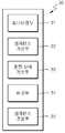
도 1을 참조하면 배터리 팩(1)은 제1 배터리 셀 그룹(10-1), 제2 배터리 셀 그룹(10-2), 제1 임피던스부(20-1), 제2 임피던스부(20-2), 배터리 관리부(30), 배터리 보호회로(40), 양극 단자(50), 음극 단자(51)를 포함한다.Referring to FIG. 1, the
제1 배터리 셀 그룹(10-1) 및 제2 배터리 셀 그룹(10-2)은 외부로부터 공급되는 전력을 저장하며, 저장된 전력을 부하로 공급한다. 제1 배터리 셀 그룹(10-1) 및 제2 배터리 셀 그룹(10-2)은 충전 가능한 2차 전지로서 각각 복수의 배터리 셀들을 포함할 수 있다. 제1 배터리 셀 그룹(10-1) 및 제2 배터리 셀 그룹(10-2)에 사용되는 배터리 셀은 니켈-카드뮴 전지(nikel-cadmium battery), 납 축전지, 니켈-수소 전지(NiMH: nickel metal hydride battery), 리튬-이온 전지(lithium ion battery), 리튬 폴리머 전지(lithium polymer battery) 등일 수 있다.The first battery cell group 10-1 and the second battery cell group 10-2 store power supplied from the outside, and supply the stored power to the load. The first battery cell group 10-1 and the second battery cell group 10-2 may be a rechargeable secondary battery and may include a plurality of battery cells, respectively. The battery cells used in the first battery cell group 10-1 and the second battery cell group 10-2 are nickel-cadmium batteries, lead storage batteries, and nickel-hydrogen batteries (NiMH). hydride batteries, lithium-ion batteries, lithium polymer batteries, and the like.
제1 임피던스부(20-1)는 제1 배터리 셀 그룹(10-1)에 직렬로 연결되며 임피던스 성분을 갖는다. 예를 들어 제1 임피던스부(20-1)는 가변 저항(R1)을 포함할 수 있다. 제1 임피던스부(20-1)는 배터리 관리부(30)에 의하여 임피던스의 크기가 조절된다.The first impedance unit 20-1 is connected in series to the first battery cell group 10-1 and has an impedance component. For example, the first impedance unit 20-1 may include a variable resistor R1. The magnitude of the impedance of the first impedance unit 20-1 is adjusted by the
제2 임피던스부(20-2)는 제2 배터리 셀 그룹(10-2)에 직렬로 연결되며 임피던스 성분을 갖는다. 예를 들어 제2 임피던스부(20-2)는 가변 저항(R2)을 포함할 수 있다. 제2 임피던스부(20-2)는 배터리 관리부(30)에 의하여 임피던스의 크기가 조절된다.The second impedance unit 20-2 is connected in series to the second battery cell group 10-2 and has an impedance component. For example, the second impedance unit 20-2 may include a variable resistor R2. The impedance of the second impedance unit 20-2 is adjusted by the
배터리 관리부(30)는 배터리 팩(1)의 전체적인 동작을 제어한다. 배터리 팩(1)은 제1 배터리 셀 그룹(10-1) 및 제2 배터리 셀 그룹(10-2)에 포함된 배터리 셀들의 전압, 온도를 모니터링하여 전압 데이터 및 온도 데이터를 수신할 수 있다. 또한 배터리 관리부(30)는 대전류 경로를 통하여 흐르는 전류를 모니터링하여 전류 데이터를 수신할 수 있다. 또한 배터리 관리부(30)는 제1 배터리 셀 그룹(10-1) 및 제2 배터리 셀 그룹(10-2)의 열화 정도를 판단하고, 판단 결과에 기초하여 제1 임피던스부(20-1) 및 제2 임피던스부(20-2)의 임피던스를 조절할 수 있다. 이하, 도 2를 참조하여, 배터리 관리부(30)에 대하여 좀 더 구체적으로 설명한다.The
도 2는 본 발명의 일 실시 예에 따른 배터리 관리부(30)를 나타내는 블록도이다. 배터리 관리부(30)는 모니터링부(31), 임피던스 계산부(32), 충전 상태 계산부(33), 비교부(34), 임피던스 조절부(35)를 포함한다.2 is a block diagram illustrating a
모니터링부(31)는 제1 배터리 셀 그룹(10-1) 및 제2 배터리 셀 그룹(10-2)의 각종 상태를 모니터링한다. 예를 들어 모니터링부(31)는 제1 배터리 셀 그룹(10-1) 및 제2 배터리 셀 그룹(10-2) 전체 또는 그에 포함되어 있는 배터리 셀들의 전압 및 온도를 모니터링한다. 또한 모니터링부(31)는 대전류 경로를 통하여 흐르는 전류나 제1 배터리 셀 그룹(10-1) 및 제2 배터리 셀 그룹(10-2)으로 유입되는 전류를 모니터링한다.The
임피던스 계산부(32)는 모니터링부(31)에 의하여 취득된 전압, 온도, 및 전류 데이터를 사용하여 제1 배터리 셀 그룹(10-1)과 제2 배터리 셀 그룹(10-2)의 내부 임피던스를 계산한다. 계산된 내부 임피던스는 제1 배터리 셀 그룹(10-1)과 제2 배터리 셀 그룹(10-2)의 열화 정도를 판단하는데 사용될 수 있다. 즉, 계산된 내부 임피던스의 크기가 클수록 열화가 많이 진행된 것으로 판단할 수 있으며, 반대로 내부 임피던스의 크기가 작을수록 열화가 적게 진행된 것으로 판단할 수 있다.The
충전 상태 계산부(33)는 모니터링부(31)에 의하여 취득된 전압, 온도, 및 전류 데이터를 사용하여 제1 배터리 셀 그룹(10-1)과 제2 배터리 셀 그룹(10-2)의 충전 상태를 계산한다. 계산된 충전 상태는 제1 임피던스부(20-1)와 제2 임피던스부(20-2)의 임피던스를 조절하기 위한 근거로 사용될 수 있다.The charging
비교부(34)는 임피던스 계산부(32)에서 계산된 제1 배터리 셀 그룹(10-1)과 제2 배터리 셀 그룹(10-2)의 내부 임피던스의 크기를 비교한다. 비교부에 의하여 내부 임피던스의 크기가 크다고 판단된 배터리 셀 그룹을 제1 임피던스부(20-1) 및 제2 임피던스부(20-2)의 임피던스 조절을 위한 기준으로 사용할 수 있다. 즉, 열화 정도가 큰 배터리 셀 그룹을 제1 임피던스부(20-1) 및 제2 임피던스부(20-2)의 임피던스 조절을 위한 기준으로 사용할 수 있다.The
또한 비교부(34)는 충전 상태 계산부(33)에서 계산된 충전 상태들 중 더 큰 내부 임피던스를 갖는(열화 정도가 큰) 것으로 판단된 배터리 셀 그룹의 충전 상태를 기준값과 비교한다. 예를 들어, 기준값은 만충전 대비 70%일 수 있다. 또한 기준값은 배터리 셀의 종류 또는 배터리 셀 그룹이 적용되는 분야에 따라서 상이할 수 있다. 예를 들어, 배터리 셀 그룹이 적용되는 분야가 에너지 저장 시스템(Energy storage system)인 경우, 기준값은 만충전 대비 80%일 수 있다.In addition, the
임피던스 조절부(35)는 비교부(34)의 충전 상태 비교 결과에 따라서 제1 임피던스부(20-1)와 제2 임피던스부(20-2)의 임피던스를 조절한다. 이때, 임피던스 조절부(35)는 다음과 같은 방식으로 조절될 수 있다.The
먼저 설명의 편의를 위하여 비교부(34)에서 제1 배터리 셀 그룹(10-1)의 내부 임피던스가 제2 배터리 셀 그룹(10-2)의 내부 임피던스보다 크다고 판단한 것으로 가정한다. 즉, 제1 배터리 셀 그룹(10-1)의 열화 정도가 제2 배터리 셀 그룹(10-2)의 열화 정도보다 크다고 가정한다.For convenience of explanation, it is assumed that the
배터리 팩(1)이 충전되는 상태일 때, 비교부(34)는 제1 배터리 셀 그룹(10-1)의 충전 상태를 기준값과 비교한다. 제1 배터리 셀 그룹(10-1)의 충전 상태가 기준값 이하일 때, 임피던스 조절부(35)는 현재 상태가 저용량 상태라고 판단한다. 저용량 상태에서는 제1 배터리 셀 그룹(10-1)과 제2 배터리 셀 그룹(10-2)에 동일한 전류가 흐르는 것이 바람직하다. 왜냐하면 양 배터리 셀 그룹에 동일한 전류가 흘러야 양 배터리 셀 그룹의 단위 시간당 충전량이 동일하게 유지될 수 있기 때문이다.When the
따라서 임피던스 조절부(35)는 제1 배터리 셀 그룹(10-1)과 제2 배터리 셀 그룹(10-2) 사이의 임피던스 매칭을 수행한다. 즉, 제1 배터리 셀 그룹(10-1)의 총 임피던스와 제2 배터리 셀 그룹(10-2)의 총 임피던스가 같도록 제1 임피던스부(20-1) 및 제2 임피던스부(20-2)의 임피던스를 조절한다. 예를 들어, 제1 배터리 셀 그룹(10-1)의 내부 임피던스가 제2 배터리 셀 그룹(10-2)의 내부 임피던스보다 크므로 임피던스 조절부(35)는 제1 임피던스부(20-1)의 임피던스는 최소로 하고, 제2 임피던스부(20-2)의 임피던스를 증가시킨다. 이로 인하여 제1 배터리 셀 그룹(10-1)의 내부 임피던스와 제1 임피던스부(20-1)의 임피던스의 합이 제2 배터리 셀 그룹(10-2)의 내부 임피던스와 제2 임피던스부(20-2)의 임피던스의 합과 같아지도록 한다.Therefore, the
그러나 상술한 임피던스 조절 방법은 예시적인 것으로 이에 한정되는 것은 아니다. 즉, 반드시 제1 임피던스부(20-1)의 임피던스가 최소로 될 필요는 없다. 다시 말해 아래와 같은 식을 만족시키도록 제1 임피던스부(20-1)와 제2 임피던스부(20-2)의 임피던스를 자유롭게 조절 가능할 것이다.
However, the above-described impedance adjustment method is exemplary and is not limited thereto. That is, the impedance of the first impedance unit 20-1 does not necessarily have to be the minimum. In other words, the impedance of the first impedance unit 20-1 and the second impedance unit 20-2 may be freely adjusted to satisfy the following equation.
제1 배터리 셀 그룹(10-1)의 내부 임피던스 - 제2 배터리 셀 그룹(10-2)의 내부 임피던스 = 제2 임피던스부(20-2)의 임피던스 - 제1 임피던스부(20-1)의 임피던스
Internal impedance of the first battery cell group 10-1-Internal impedance of the second battery cell group 10-2 = Impedance of the second impedance unit 20-2-of the first impedance unit 20-1 impedance
한편, 제1 배터리 셀 그룹(10-1)의 충전 상태가 기준값보다 클 때, 임피던스 조절부(35)는 현재 상태가 고용량 상태라고 판단한다. 고용량 상태에서는 제1 배터리 셀 그룹(10-1)의 전압이 충전 한계 전압에 근접하게 된다. 충전이 진행되어 제1 배터리 셀 그룹(10-1)의 전압이 충전 한계 전압에 도달하면 충전이 종료된다. 그러나 제2 배터리 셀 그룹(10-2)은 제1 배터리 셀 그룹(10-1)에 비하여 열화 정도가 낮기때문에 상대적으로 충전 가능한 용량이 많이 남아있게 된다. 따라서 고용량 상태에서는 제2 배터리 셀 그룹(10-2)으로 유입되는 충전 전류가 제1 배터리 셀 그룹(10-1)으로 유입되는 충전 전류보다 크도록 하는 것이 바람직하다.Meanwhile, when the state of charge of the first battery cell group 10-1 is greater than the reference value, the
따라서 임피던스 조절부(35)는 제1 배터리 셀 그룹(10-1)의 총 임피던스가 제2 배터리 셀 그룹(10-2)의 총 임피던스보다 크도록 제1 임피던스부(20-1) 및 제2 임피던스부(20-2)의 임피던스를 조절한다. 예를 들어, 임피던스 조절부(35)는 제2 임피던스부(20-2)의 임피던스는 최소로 하고, 제1 임피던스부(20-1)의 임피던스를 증가시킨다. 이로 인하여 제1 배터리 셀 그룹(10-1)의 내부 임피던스와 제1 임피던스부(20-1)의 임피던스의 합이 제2 배터리 셀 그룹(10-2)의 내부 임피던스와 제2 임피던스부(20-2)의 임피던스의 합보다 커지며, 따라서 대전류 경로를 통하여 유입되는 충전 전류가 분배될 때 제1 배터리 셀 그룹(10-1)에 유입되는 충전 전류의 양보다 제2 배터리 셀 그룹(10-2)에 유입되는 충전 전류의 양이 커지게 된다. 이때, 제1 임피던스부(20-1)와 제2 임피던스부(20-2)의 임피던스는 제1 배터리 셀 그룹(10-1)과 제2 배터리 셀 그룹(10-2)의 열화 정도의 차이에 의하여 결정될 수 있을 것이다.Therefore, the
상기와 같은 임피던스의 조절에 의하여 제1 배터리 셀 그룹(10-1)과 제2 배터리 셀 그룹(10-2)이 동시에 만충전 상태가 되도록 할 수 있게 된다.By adjusting the impedance as described above, the first battery cell group 10-1 and the second battery cell group 10-2 can be brought into a fully charged state at the same time.
다음으로 배터리 팩(1)이 배터리 팩(1)이 방전되는 상태일 때에 대하여 설명한다. 배터리 팩(1)이 방전되는 상태일 때, 비교부(34)는 제1 배터리 셀 그룹(10-1)의 충전 상태를 기준값과 비교한다. 제1 배터리 셀 그룹(10-1)의 충전 상태가 기준값보다 클 때, 임피던스 조절부(35)는 현재 상태가 고용량 상태라고 판단한다. 고용량 상태에서는 제1 배터리 셀 그룹(10-1)과 제2 배터리 셀 그룹(10-2)에 동일한 전류가 흐르는 것이 바람직하다. 왜냐하면 양 배터리 셀 그룹에 동일한 전류가 흘러야 양 배터리 셀 그룹의 단위 시간당 방전량이 동일하게 유지될 수 있기 때문이다.Next, the
따라서 임피던스 조절부(35)는 제1 배터리 셀 그룹(10-1)과 제2 배터리 셀 그룹(10-2) 사이의 임피던스 매칭을 수행한다. 즉, 제1 배터리 셀 그룹(10-1)의 총 임피던스와 제2 배터리 셀 그룹(10-2)의 총 임피던스가 같도록 제1 임피던스부(20-1) 및 제2 임피던스부(20-2)의 임피던스를 조절한다. 예를 들어, 제1 배터리 셀 그룹(10-1)의 내부 임피던스가 제2 배터리 셀 그룹(10-2)의 내부 임피던스보다 크므로 임피던스 조절부(35)는 제1 임피던스부(20-1)의 임피던스는 최소로 하고, 제2 임피던스부(20-2)의 임피던스를 증가시킨다. 이로 인하여 제1 배터리 셀 그룹(10-1)의 내부 임피던스와 제1 임피던스부(20-1)의 임피던스의 합이 제2 배터리 셀 그룹(10-2)의 내부 임피던스와 제2 임피던스부(20-2)의 임피던스의 합과 같아지도록 한다.Therefore, the
그러나 상술한 임피던스 조절 방법은 예시적인 것으로 이에 한정되는 것은 아니다. 즉, 반드시 제1 임피던스부(20-1)의 임피던스가 최소로 될 필요는 없다. 다시 말해 아래와 같은 식을 만족시키도록 제1 임피던스부(20-1)와 제2 임피던스부(20-2)의 임피던스를 자유롭게 조절 가능할 것이다.
However, the above-described impedance adjustment method is exemplary and is not limited thereto. That is, the impedance of the first impedance unit 20-1 does not necessarily have to be the minimum. In other words, the impedance of the first impedance unit 20-1 and the second impedance unit 20-2 may be freely adjusted to satisfy the following equation.
제1 배터리 셀 그룹(10-1)의 내부 임피던스 - 제2 배터리 셀 그룹(10-2)의 내부 임피던스 = 제2 임피던스부(20-2)의 임피던스 - 제1 임피던스부(20-1)의 임피던스
Internal impedance of the first battery cell group 10-1-Internal impedance of the second battery cell group 10-2 = Impedance of the second impedance unit 20-2-of the first impedance unit 20-1 impedance
한편, 제1 배터리 셀 그룹(10-1)의 충전 상태가 기준값 이하일 때, 임피던스 조절부(35)는 현재 상태가 저용량 상태라고 판단한다. 저용량 상태에서는 제1 배터리 셀 그룹(10-1)의 전압이 방전 한계 전압에 근접하게 된다. 방전이 진행되어 제1 배터리 셀 그룹(10-1)의 전압이 방전 한계 전압에 도달하면 방전이 종료된다. 그러나 제2 배터리 셀 그룹(10-2)은 제1 배터리 셀 그룹(10-1)에 비하여 열화 정도가 낮기때문에 상대적으로 방전 가능한 용량이 많이 남아있게 된다. 따라서 저용량 상태에서는 제2 배터리 셀 그룹(10-2)으로부터 나오는 방전 전류가 제1 배터리 셀 그룹(10-1)으로부터 나오는 방전 전류보다 크도록 하는 것이 바람직하다.Meanwhile, when the state of charge of the first battery cell group 10-1 is less than or equal to the reference value, the
따라서 임피던스 조절부(35)는 제1 배터리 셀 그룹(10-1)의 총 임피던스가 제2 배터리 셀 그룹(10-2)의 총 임피던스보다 크도록 제1 임피던스부(20-1) 및 제2 임피던스부(20-2)의 임피던스를 조절한다. 예를 들어, 임피던스 조절부(35)는 제2 임피던스부(20-2)의 임피던스는 최소로 하고, 제1 임피던스부(20-1)의 임피던스를 증가시킨다. 이로 인하여 제1 배터리 셀 그룹(10-1)의 내부 임피던스와 제1 임피던스부(20-1)의 임피던스의 합이 제2 배터리 셀 그룹(10-2)의 내부 임피던스와 제2 임피던스부(20-2)의 임피던스의 합보다 커지며, 제1 배터리 셀 그룹(10-1)으로부터 나오는 방전 전류의 양보다 제2 배터리 셀 그룹(10-2)으로부터 나오는 방전 전류의 양이 커지게 된다. 이때, 제1 임피던스부(20-1)와 제2 임피던스부(20-2)의 임피던스는 제1 배터리 셀 그룹(10-1)과 제2 배터리 셀 그룹(10-2)의 열화 정도의 차이에 의하여 결정될 수 있을 것이다.Therefore, the
본 실시 예에서는 충전 및 방전시의 기준값이 동일한 것으로 설명하였으나, 이에 한정되는 것은 아니다. 예를 들어, 충전시에는 열화 정도가 큰 배터리 셀 그룹의 충전 상태가 70%를 넘었는지 여부를 기준으로 하여 제1 임피던스부(20-1) 및 제2 임피던스부(20-2)의 임피던스를 조절한다. 그리고, 방전시에는 열화 정도가 큰 배터리 셀 그룹의 충전 상태가 30% 미만이 되었는지 여부를 기준으로 하여 제1 임피던스부(20-1) 및 제2 임피던스부(20-2)의 임피던스를 조절한다. 즉, 충전시와 방전시의 기준값이 서로 상이하도록 설정할 수도 있을 것이다.In the present exemplary embodiment, the reference values at the time of charging and discharging are the same, but the present invention is not limited thereto. For example, during charging, the impedances of the first impedance unit 20-1 and the second impedance unit 20-2 are determined based on whether the state of charge of the battery cell group having a large deterioration degree is greater than 70%. Adjust. During discharge, the impedances of the first impedance unit 20-1 and the second impedance unit 20-2 are adjusted based on whether or not the state of charge of the battery cell group with large deterioration is less than 30%. . That is, the reference value at the time of charging and discharging may be set to be different from each other.
배터리 보호회로(40)는 제1 배터리 셀 그룹(10-1) 및 제2 배터리 셀 그룹(10-2)과 충전기와 연결되는 양극 단자(50) 및 음극 단자(51) 사이에 구비되어 충전 및 방전 전류의 흐름을 제어한다. 배터리 보호회로(40)는 배터리 관리부(30)의 제어에 따라서 동작하는 수동 소자나 자체적으로 동작하는 능동 소자 등을 포함할 수 있다. 예를 들어, 배터리 보호회로(40)는 배터리 관리부(30)의 제어에 의하여 온/오프가 제어되어 충전 전류 또는 방전 전류가 흐르게 하거나 충전 전류나 방전 전류의 흐름을 차단하는 충전 제어 스위치 및 방전 제어 스위치를 포함할 수 있다. 또한 배터리 보호회로(40)는 충방전 경로에 과전류가 흐르는 경우 전류의 흐름을 영구히 차단하기 위하여 충방전 경로를 개방시키는 퓨즈를 포함할 수 있다.The
양극 단자(50) 및 음극 단자(51)는 충전기 또는 외부 전자기기, 예컨데 휴대폰이나 노트북과 연결되는 단자이다. 양극 단자(50) 및 음극 단자(51)가 충전기와 연결될 때에는 양극 단자(50)를 통하여 충전 전류가 유입되고 음극 단자(51)를 통하여 충전 전류가 나온다. 반대로 양극 단자(50) 및 음극 단자(51)가 외부 전자기기와 연결될 때에는 양극 단자(50)를 통하여 방전 전류가 나오고 음극 단자(51)를 통하여 방전 전류가 유입된다.The
본 실시 예에서는 양극 단자(50) 및 음극 단자(51)가 충전기와 외부 전자기기에 모두 연결되는 것으로 도시하였으나 이에 한정되는 것은 아니다. 예를 들어 충전용 단자와 방전용 단자를 각각 별도로 구비하고, 충전용 단자는 충전기와 연결되며, 방전용 단자는 외부 전자기기와 연결되도록 할 수도 있을 것이다.In the present embodiment, the
도 3은 본 발명의 일 실시 예에 따른 배터리 팩(1)의 제어방법을 나타내는 흐름도이다.3 is a flowchart illustrating a control method of the
도 3을 참조하면, 모니터링부(31)는 제1 배터리 셀 그룹(10-1)과 제2 배터리 셀 그룹(10-2)을 모니터링한다(S301). 예를 들어 모니터링부(31)는 제1 배터리 셀 그룹(10-1)과 제2 배터리 셀 그룹(10-2)의 전압, 온도와 제1 배터리 셀 그룹(10-1)과 제2 배터리 셀 그룹(10-2)에 흐르는 전류의 크기를 모니터링할 수 있다.Referring to FIG. 3, the
임피던스 계산부(32)는 모니터링부(31)의 모니터링 결과를 수신하여 제1 배터리 셀 그룹(10-1)과 제2 배터리 셀 그룹(10-2)의 내부 임피던스를 계산한다(S302). 즉, 제1 배터리 셀 그룹(10-1)과 제2 배터리 셀 그룹(10-2)의 열화 정도를 계산한다.The
비교부(34)는 임피던스 계산부(32)의 계산 결과를 사용하여 제1 배터리 셀 그룹(10-1)의 내부 임피던스가 제2 배터리 셀 그룹(10-2)의 내부 임피던스보다 큰지를 판단한다(S303).The
임피던스 조절부(35)는 제1 배터리 셀 그룹(10-1)의 내부 임피던스가 더 큰 경우 제1 배터리 셀 그룹(10-1)의 충전 상태를 기준으로 제1 임피던스부(20-1) 및 제2 임피던스부(20-2)의 임피던스를 조절한다(S304). 임피던스의 조절을 위하여 충전 상태 계산부(33)는 모니터링부(31)의 모니터링 결과를 사용하여 제1 배터리 셀 그룹(10-1)과 제2 배터리 셀 그룹(10-2)의 충전 상태를 계산할 수 있을 것이다.When the internal impedance of the first battery cell group 10-1 is greater, the
한편, 임피던스 조절부(35)는 제1 배터리 셀 그룹(10-1)의 내부 임피던스가 제2 배터리 셀 그룹(10-2)의 내부 임피던스 이하인 경우 제2 배터리 셀 그룹(10-2)의 충전 상태를 기준으로 제1 임피던스부(20-1) 및 제2 임피던스부(20-2)의 임피던스를 조절한다(S304).Meanwhile, the
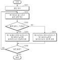
도 4는 본 발명의 다른 실시 예에 따른 배터리 팩(1)의 제어방법을 나타내는 흐름도이다. 본 실시 예에서는 제1 배터리 셀 그룹(10-1)이 제2 배터리 셀 그룹(10-2)보다 열화 정도가 큰 것으로 가정하여 설명한다.4 is a flowchart illustrating a control method of the
도 4를 참조하면, 충전을 개시하면(S401), 충전 상태 계산부(33)는 열화 정도가 더 큰 제1 배터리 셀 그룹(10-1)의 충전 상태를 계산한다(S402). 그리고 계산된 충전 상태가 기준값 이하인지를 판단한다(S403).Referring to FIG. 4, when charging is started (S401), the charging
계산된 충전 상태가 기준값 이하일 때에는 제1 배터리 셀 그룹(10-1)이 저용량 상태라고 판단하고, 제1 배터리 셀 그룹(10-1)과 제2 배터리 셀 그룹(10-2) 사이의 임피던스 매칭이 필요한 것으로 판단한다. 따라서 임피던스 조절부(35)는 제2 임피던스부(20-2)의 임피던스가 제1 임피던스부(20-1)의 임피던스보다 크도록 조절한다(S404).When the calculated state of charge is less than or equal to the reference value, it is determined that the first battery cell group 10-1 is in a low capacity state, and impedance matching between the first battery cell group 10-1 and the second battery cell group 10-2 is performed. I think this is necessary. Therefore, the
한편 계산된 충전 상태가 기준값보다 클 때에는 제1 배터리 셀 그룹(10-1)이 고용량 상태라고 판단하여, 임피던스 조절부(35)는 제1 임피던스부(20-1)의 임피던스가 제2 임피던스부(20-2)의 임피던스보다 크도록 조절한다(S405).Meanwhile, when the calculated state of charge is greater than the reference value, it is determined that the first battery cell group 10-1 is in a high capacity state, and the
그리고는 충전이 종료되었는지를 판단하고(S406), 충전이 종료되지 않았으면 S402 단계로 돌아간다. S406 단계에서 충전이 종료되었다고 판단한 경우에는 충전 동작을 중지한다.Then, it is determined whether the charging is finished (S406), and if the charging is not finished, the process returns to the step S402. If it is determined in step S406 that the charging is finished, the charging operation is stopped.
도 5는 본 발명의 다른 실시 예에 따른 배터리 팩(1)의 제어방법을 나타내는 흐름도이다. 본 실시 예에서도 제1 배터리 셀 그룹(10-1)이 제2 배터리 셀 그룹(10-2)보다 열화 정도가 큰 것으로 가정하여 설명한다.5 is a flowchart illustrating a method of controlling the
도 5를 참조하면, 방전을 개시하면(S501), 충전 상태 계산부(33)는 열화 정도가 더 큰 제1 배터리 셀 그룹(10-1)의 충전 상태를 계산한다(S502). 그리고 계산된 충전 상태가 기준값 이하인지를 판단한다(S503).Referring to FIG. 5, when the discharge is started (S501), the charging
계산된 충전 상태가 기준값보다 클 때에는 제1 배터리 셀 그룹(10-1)이 고용량 상태라고 판단하고, 제1 배터리 셀 그룹(10-1)과 제2 배터리 셀 그룹(10-2) 사이의 임피던스 매칭이 필요한 것으로 판단한다. 따라서 임피던스 조절부(35)는 제2 임피던스부(20-2)의 임피던스가 제1 임피던스부(20-1)의 임피던스보다 크도록 조절한다(S504).When the calculated state of charge is greater than the reference value, it is determined that the first battery cell group 10-1 is in a high capacity state, and the impedance between the first battery cell group 10-1 and the second battery cell group 10-2 is determined. It is determined that matching is necessary. Therefore, the
한편 계산된 충전 상태가 기준값 이하일 때에는 제1 배터리 셀 그룹(10-1)이 저용량 상태라고 판단하여, 임피던스 조절부(35)는 제1 임피던스부(20-1)의 임피던스가 제2 임피던스부(20-2)의 임피던스보다 크도록 조절한다(S505).Meanwhile, when the calculated state of charge is less than or equal to the reference value, it is determined that the first battery cell group 10-1 is in a low capacity state, and the
그리고는 방전이 종료되었는지를 판단하고(S506), 방전이 종료되지 않았으면 S502 단계로 돌아간다. S506 단계에서 방전이 종료되었다고 판단한 경우에는 방전 동작을 중지한다.Then, it is determined whether the discharge is finished (S506), and if the discharge is not finished, the process returns to step S502. If it is determined in step S506 that the discharge is finished, the discharge operation is stopped.
배터리 셀은 충전 및 방전이 반복될수록 열화가 진행되며, 이로 인하여 내부 임피던스, 예컨데 내부 저항이 증가하게 된다. 그런데 열화의 진행 정도는 배터리 셀마다 동일하지는 않으며 편차가 발생하기 마련이다. 따라서 도 1에서와 같이 제1 배터리 셀 그룹(10-1)과 제2 배터리 셀 그룹(10-2)이 병렬로 연결되어 있을 때 각각의 배터리 셀 그룹의 열화 정도가 다른 경우에는 배터리 팩(1)의 충전 효율 및 방전 효율이 떨어지게 된다.As the battery cell is repeatedly charged and discharged, the battery cell deteriorates, thereby increasing the internal impedance, for example, the internal resistance. However, the progress of deterioration is not the same for each battery cell, and a deviation occurs. Therefore, when the first battery cell group 10-1 and the second battery cell group 10-2 are connected in parallel as shown in FIG. 1, when the deterioration degree of each battery cell group is different, the battery pack 1 ) Charging efficiency and discharge efficiency are reduced.
예를 들어, 제1 배터리 셀 그룹(10-1)의 열화 정도가 높은 경우, 제2 배터리 셀 그룹(10-2)의 충전이 종료되지 않았음에도 불구하고 제1 배터리 셀 그룹(10-1)의 전압이 충전 한계 전압에 도달하여 배터리 팩(1) 전체의 충전이 종료될 수 있다. 마찬가지로 방전시에는 제2 배터리 셀 그룹(10-2)의 방전이 종료되지 않았음에도 불구하고 제1 배터리 셀 그룹(10-1)의 전압이 방전 한계 전압에 도달하여 배터리 팩(1) 전체의 방전이 종료될 수 있다. 즉, 배터리 팩(1)이 가지는 성능을 최대로 발휘하지 못하게 된다.For example, when the degree of deterioration of the first battery cell group 10-1 is high, the first battery cell group 10-1 may not be terminated even though the charging of the second battery cell group 10-2 is not terminated. When the voltage at reaches the charge limit voltage, charging of the
그러나 상기와 같이 제1 배터리 셀 그룹(10-1)과 제2 배터리 셀 그룹(10-2)의 열화 정도와 충전 상태에 따라서 제1 임피던스부(20-1)와 제2 임피던스부(20-2)의 임피던스를 조절함으로 인하여 배터리 팩(1)이 가지는 성능을 최대로 발휘할 수 있게 된다.However, as described above, the first impedance unit 20-1 and the second impedance unit 20-may vary depending on the degree of deterioration and the state of charge of the first battery cell group 10-1 and the second battery cell group 10-2. By adjusting the impedance of 2) it is possible to maximize the performance of the battery pack (1).
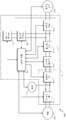
도 6은 본 발명의 다른 실시 예에 따른 배터리 팩(2)의 구성을 나타내는 블록도이다. 본 실시 예의 배터리 팩(2)은 도 1에 따른 배터리 팩(1)과 상이한 부분을 중심으로 설명하도록 한다.6 is a block diagram illustrating a configuration of a
도 6을 참조하면, 배터리 팩(2)은 3 이상의 배터리 셀 그룹(10-1~10-n)과 이들 배터리 셀 그룹(10-1~10-n)에 각각 직렬로 연결된 3 이상의 임피던스부(20-1~20-n)를 포함한다. 배터리 셀 그룹(10-1~10-n)의 개수와 임피던스부(20-1~20-n)의 개수는 같도록 할 수 있다.Referring to FIG. 6, the
배터리 관리부(36)는 복수의 배터리 셀 그룹(10-1~10-n)들을 모니터링하여 전압, 전류, 및 온도 데이터를 획득한다. 그리고 배터리 관리부(36)는 모니터링 결과를 사용하여 복수의 배터리 셀 그룹(10-1~10-n)의 내부 임피던스, 즉 열화 정도 및 충전 상태를 계산한다.The
또한 배터리 관리부(36)는 열화 정도가 가장 큰 하나의 배터리 셀 그룹을 기준으로 복수의 임피던스부(20-1~20-n)들의 임피던스를 조절한다.In addition, the
본 실시 예에 따른 배터리 관리부(36)는 도 2의 배터리 관리부(30)와 실질적으로 동일하다. 따라서 복수의 임피던스부(20-1~20-n)의 임피던스의 조절 방법에 대한 구체적인 설명은 생략하도록 한다.The
상기와 같이 배터리 셀 그룹(10-1~10-n)의 개수가 2개를 초과하는 경우라도 배터리 셀 그룹(10-1~10-n)들의 열화 정도와 충전 상태에 따라서 복수의 임피던스부(20-1~20-n)의 임피던스를 조절함으로 인하여 배터리 팩(2)이 가지는 성능을 최대로 발휘할 수 있게 된다.Even when the number of battery cell groups 10-1 to 10-n exceeds two as described above, the plurality of impedance units ( By adjusting the impedance of 20-1 ~ 20-n) it is possible to maximize the performance of the battery pack (2).
도 7은 본 발명의 일 실시 예에 따른 배터리 팩(2)이 적용된 에너지 저장 시스템(100)의 구성을 나타내는 블록도이다.FIG. 7 is a block diagram illustrating a configuration of an
도 7을 참조하면, 본 실시 예에 따른 에너지 저장 시스템(110)은 발전 시스템(120), 계통(130)과 연계하여 부하(140)에 전력을 공급한다.Referring to FIG. 7, the
발전 시스템(120)은 에너지원을 이용하여 전력을 생산하는 시스템이다. 발전 시스템(120)은 생산한 전력을 에너지 저장 시스템(110)에 공급한다. 발전 시스템(120)은 태양광 발전 시스템, 풍력 발전 시스템, 조력 발전 시스템 등일 수 있다. 그러나 이는 예시적인 것으로 발전 시스템(120)은 상기 언급한 종류에 한정되는 것은 아니다. 태양열이나 지열 등, 신재생 에너지를 이용하여 전력을 생산하는 발전 시스템을 모두 포함할 수 있다. 특히 태양광을 이용하여 전기 에너지를 생산하는 태양 전지는, 각 가정 또는 공장 등에 설치하기 용이하여, 각 가정이나 공장에 분산된 에너지 저장 시스템(110)에 적용하기에 적합하다. 발전 시스템(120)은 다수의 발전 모듈을 병렬로 구비하고 발전 모듈별로 전력을 생산함으로써 대용량 에너지 시스템을 구성할 수 있다.The
계통(130)은 발전소, 변전소, 송전선 등을 구비한다. 계통(130)은 정상 상태인 경우, 에너지 저장 시스템(110)으로 전력을 공급하여 부하(140) 및/또는 배터리 시스템(117)에 전력이 공급되도록 하고, 에너지 저장 시스템(110)으로부터 전력을 공급받는다. 계통(130)이 비정상 상태인 경우, 계통(130)으로부터 에너지 저장 시스템(110)으로의 전력 공급은 중단되고, 에너지 저장 시스템(110)으로부터 계통(130)으로의 전력 공급 또한 중단된다.The
부하(140)는 발전 시스템(120)에서 생산된 전력, 배터리 시스템(117)에 저장된 전력, 또는 계통(130)으로부터 공급된 전력을 소비한다. 가정이나 공장 등이 부하(140)의 일 예일 수 있다.The
에너지 저장 시스템(110)은 발전 시스템(120)에서 생산한 전력을 배터리 시스템(117)에 저장하고, 생산한 전력을 계통(130)으로 공급할 수 있다. 에너지 저장 시스템(110)은 배터리 시스템(117)에 저장된 전력을 계통(130)으로 공급하거나, 계통(130)으로부터 공급된 전력을 배터리 시스템(117)에 저장할 수도 있다. 또한, 에너지 저장 시스템(110)은 계통(130)이 비정상 상태일 경우, 예를 들면 정전이 발생한 경우에는 UPS(Uninterruptible Power Supply) 동작을 수행하여 부하(140)에 전력을 공급할 수 있다. 또한 에너지 저장 시스템(110)은 계통(130)이 정상인 상태에서도 발전 시스템(120)이 생산한 전력이나 배터리 시스템(117)에 저장되어 있는 전력을 부하(140)로 공급할 수 있다.The
에너지 저장 시스템(110)은 전력 변환을 제어하는 전력 변환 시스템(Power Conversion System, 이하 'PCS'라 함)(111), 배터리 시스템(117), 제1 스위치(118), 및 제2 스위치(119) 등을 포함한다.The
PCS(111)는 발전 시스템(120), 계통(130), 배터리 시스템(117)의 전력을 적절한 전력으로 변환하여 필요한 곳에 공급한다. PCS(111)는 전력 변환부(112), DC 링크부(113), 인버터(114), 컨버터(115), 통합 제어기(116)를 포함한다.The
전력 변환부(112)는 발전 시스템(120)과 DC 링크부(113) 사이에 연결되는 전력 변한 장치이다. 전력 변환부(112)는 발전 시스템(120)에서 생산한 전력을 DC 링크부(113)로 전달하며, 이때 출력 전압을 직류 링크 전압으로 변환한다.The
전력 변환부(112)는 발전 시스템(120)의 종류에 따라서 컨버터, 정류회로 등의 전력 변환 회로로 구성될 수 있다. 발전 시스템(120)이 생산하는 전력이 직류인 경우, 전력 변환부(112)는 직류를 직류로 변환하기 위한 컨버터일 수 있다. 발전 시스템(120)이 생산하는 전력이 교류인 경우, 전력 변환부(112)는 교류를 직류로 변환하기 위한 정류회로일 수 있다. 특히, 발전 시스템(120)이 태양광 발전 시스템인 경우, 전력 변환부(112)는 일사량, 온도 등의 변화에 따라서 발전 시스템(120)에서 생산하는 전력을 최대로 얻을 수 있도록 최대 전력 포인트 추적(Maximum Power Point Tracking) 제어를 수행하는 MPPT 컨버터를 포함할 수 있다. 전력 변환부(112)는 발전 시스템(120)에서 생산되는 전력이 없을 때에는 동작을 중지하여 컨버터 등에서 소비되는 전력을 최소화시킬 수도 있다.The
직류 링크 전압은 발전 시스템(120) 또는 계통(130)에서의 순시 전압 강하, 부하(140)에서의 피크 부하 발생 등으로 인하여 그 크기가 불안정해 지는 경우가 있다. 그러나 직류 링크 전압은 컨버터(115) 및 인버터(114)의 정상 동작을 위하여 안정화될 필요가 있다. DC 링크부(113)는 전력 변환부(112)와 인버터(114) 사이에 연결되어 직류 링크 전압을 일정하게 유지시킨다. DC 링크부(113)로서, 예를 들어 대용량 커패시터 등을 사용할 수 있다.The DC link voltage may become unstable due to an instantaneous voltage drop in the
인버터(114)는 DC 링크부(113)와 제1 스위치(118) 사이에 연결되는 전력 변환 장치이다. 인버터(114)는 방전 모드에서 발전 시스템(120) 및/또는 배터리 시스템(117)으로부터 출력된 직류 링크 전압을 계통(130)의 교류 전압으로 변환하여 출력하는 인버터를 포함할 수 있다. 또한, 인버터(114)는 충전 모드에서 계통(130)의 전력을 배터리 시스템(117)에 저장하기 위하여, 계통(130)의 교류 전압을 정류하고 직류 링크 전압으로 변환하여 출력하는 정류 회로를 포함할 수 있다.The
인버터(114)는 입력과 출력의 방향이 변할 수 있는 양방향 인버터일 수 있다. 혹은, 인버터(114)는 입력과 출력의 방향이 변할 수 있도록 복수의 인버터를 포함할 수도 있을 것이다.The
인버터(114)는 계통(130)으로 출력되는 교류 전압에서 고조파를 제거하기 위한 필터를 포함할 수 있다. 또한 인버터(114)는 무효 전력의 발생을 억제하기 위하여 인버터(114)로부터 출력되는 교류 전압의 위상과 계통(130)의 교류 전압의 위상을 동기화시키기 위한 위상 동기 루프(PLL) 회로를 포함할 수 있다. 그 밖에, 인버터(114)는 전압 변동 범위 제한, 역률 개선, 직류 성분 제거, 과도현상(transient phenomena) 보호 등과 같은 기능을 수행할 수 있다. 인버터(114)는 사용되지 않을 때, 전력 소비를 최소화하기 위하여 동작을 중지시킬 수도 있다.The
컨버터(115)는 DC 링크부(113)와 배터리 시스템(117) 사이에 연결되는 전력 변환 장치이다. 컨버터(115)는 방전 모드에서 배터리 시스템(117)에 저장된 전력을 인버터(114)에서 요구하는 전압 레벨 즉, 직류 링크 전압으로 DC-DC 변환하여 출력하는 컨버터를 포함한다. 또한, 컨버터(115)는 충전 모드에서 전력 변환부(112)에서 출력되는 전력이나 인버터(114)에서 출력되는 전력의 전압을 배터리 시스템(117)에서 요구하는 전압 레벨, 즉 충전 전압으로 DC-DC 변환하는 컨버터를 포함한다. 컨버터(115)는 배터리 시스템(117)의 충전 또는 방전이 필요없는 경우에는 동작을 중지시켜 전력 소비를 최소화할 수도 있다.The
컨버터(115)는 입력과 출력의 방향이 변할 수 있는 양방향 컨버터일 수 있다. 혹은 컨버터(115)는 입력과 출력의 방향이 변할 수 있도록 복수의 컨버터를 포함할 수도 있을 것이다.The
통합 제어기(116)는 발전 시스템(120), 계통(130), 배터리 시스템(117), 및 부하(140)의 상태를 모니터링 하고, 모니터링 결과에 따라서 전력 변환부(112), 인버터(114), 컨버터(115), 배터리 시스템(117), 제1 스위치(118), 제2 스위치(119)의 동작을 제어한다. 통합 제어기(116)는 계통(130)에 정전이 발생하였는지 여부, 발전 시스템(120)에서 전력이 생산되는지 여부, 발전 시스템(120)에서 전력을 생산하는 경우 그 생산량, 배터리 시스템(117)의 충전 상태, 부하(140)의 소비 전력량, 시간 등을 모니터링 할 수 있다. 또한 통합 제어기(116)는 계통(130)에 정전이 발생하는 등, 부하(140)로 공급할 전력이 충분하지 않은 경우에는 부하(140) 내에 포함된 전력 사용 기기들에 대하여 우선 순위를 정하고, 우선 순위가 높은 전력 사용 기기로 전력을 공급하도록 부하(140)를 제어할 수도 있을 것이다.The
제1 스위치(118) 및 제2 스위치(119)는 인버터(114)와 계통(130) 사이에 직렬로 연결되며, 통합 제어기(116)의 제어에 따라서 on/off 동작을 수행하여 발전 시스템(120)과 계통(130) 사이의 전류의 흐름을 제어한다. 제1 스위치(118)와 제2 스위치(119)는 발전 시스템(120), 계통(130), 및 배터리 시스템(117)의 상태에 따라서 on/off가 결정될 수 있다.The
구체적으로, 발전 시스템(120) 및/또는 배터리 시스템(117)의 전력을 부하(140)로 공급하는 경우 또는 계통(130)의 전력을 배터리 시스템(117)에 공급하는 경우, 제1 스위치(118)를 on 상태로 한다. 발전 시스템(120) 및/또는 배터리 시스템(117)의 전력을 계통(130)으로 공급하는 경우 또는 계통(130)의 전력을 부하(140) 및/또는 배터리 시스템(117)에 공급하는 경우에는 제2 스위치(119)를 on 상태로 한다.Specifically, when supplying power of the
한편, 계통(130)에서 정전이 발생한 경우에는, 제2 스위치(119)를 off 상태로 하고 제1 스위치(118)를 on 상태로 한다. 즉, 발전 시스템(120) 및/또는 배터리 시스템(117)으로부터의 전력을 부하(140)에 공급하는 동시에, 부하(140)로 공급되는 전력이 계통(130) 측으로 흐르는 것을 방지한다. 이로 인하여 에너지 저장 시스템(110)의 단독운전을 방지하여 계통(130)의 전력선 등에서 작업하는 인부가 에너지 저장 시스템(110)으로부터의 전력에 의하여 감전되는 등의 사고를 방지할 수 있게 한다.On the other hand, when a power failure occurs in the
제1 스위치(118) 및 제2 스위치(119)로는 큰 전류에 견딜 수 있는 릴레이(relay) 등의 스위칭 장치가 사용될 수 있다.As the
배터리 시스템(117)은 발전 시스템(120) 및/또는 계통(130)의 전력을 공급받아 저장하고, 부하(140) 또는 계통(130)에 저장하고 있는 전력을 공급한다. 배터리 시스템(117)은 전력을 저장하는 부분과 이를 제어 및 보호하는 부분을 포함할 수 있다. 본 실시 예의 배터리 시스템(117)은 도 1 내지 도 6에 따른 배터리 팩(1,2)의 개념이 적용될 수 있다. 이하, 도 8을 참조하여 배터리 시스템(117)에 대하여 구체적으로 살펴보도록 한다.The
도 8은 본 발명의 일 실시 예에 따른 배터리 시스템(117)의 구성을 나타내는 블록도이다.8 is a block diagram illustrating a configuration of a
도 8을 참조하면, 에너지 저장 시스템(110)에서는 부하(140)에 충분한 전력을 공급하기 위하여 복수의 배터리 랙(200-1~200-n)이 병렬로 구비될 수 있다. 각 배터리 랙(200-1~200-n)은 랙 배터리(210-1~210-n), 랙 임피던스부(220-1~220-n), 랙 BMS(230-1~230-n)를 각각 포함할 수 있다. 그리고 배터리 시스템(117)은 복수의 배터리 랙(200-1~200-n) 전체를 제어하기 위하여 시스템 BMS(300)을 포함할 수 있다.Referring to FIG. 8, in the
랙 배터리(210-1~210-n)는 전기 에너지를 저장하는 부분으로서 도 6의 복수의 배터리 셀 그룹(10-1~10-n)에 대응될 수 있다.The rack batteries 210-1 to 210-n may store electrical energy and may correspond to the plurality of battery cell groups 10-1 to 10-n of FIG. 6.
랙 BMS(230-1~230-n)는 랙 배터리(210-1~210-n)를 모니터링하여 전압, 전류, 및 온도 데이터를 획득하고, 이를 시스템 BMS(300)로 전송할 수 있다. 또한 랙 BMS(230-1~230-n)는 시스템 BMS(300)의 제어에 따라서 랙 임피던스부(220-1~220-n)의 임피던스를 조절할 수 있다. 즉, 랙 BMS(230-1~230-n)는 도 2의 모니터링부(31), 임피던스 조절부(35)에 대응될 수 있다.The rack BMSs 230-1 to 230-n may monitor the rack batteries 210-1 to 210-n to obtain voltage, current, and temperature data, and may transmit the same to the
또한 랙 BMS(230-1~230-n)는 획득한 전압, 전류, 및 온도 데이터로부터 랙 배터리(210-1~210-n)의 열화 정도나 충전 상태를 계산할 수도 있다. 따라서 랙 BMS(230-1~230-n)는 도 2의 임피던스 계산부(32) 및 충전 상태 계산부(33)에 대응될 수도 있을 것이다.In addition, the rack BMSs 230-1 to 230-n may calculate the degree of deterioration or the state of charge of the rack batteries 210-1 to 210-n from the obtained voltage, current, and temperature data. Accordingly, the rack BMSs 230-1 to 230-n may correspond to the
한편, 시스템 BMS(300)는 랙 BMS(230-1~230-n)로부터 모니터링 결과, 즉 전압, 전류 및 온도 데이터를 수신하고, 수신한 데이터로부터 랙 배터리(210-1~210-n)의 열화 정도나 충전 상태를 계산할 수 있다. 이러한 경우, 시스템 BMS(300)가 도 2의 임피던스 계산부(32) 및 충전 상태 계산부(33)에 대응될 수 있다. 그러나 시스템 BMS(300)는 이에 한정되는 것은 아니며, 랙 BMS(230-1~230-n)로부터 계산이 완료된 열화 정도 및 충전 상태에 대한 데이터를 수신할 수도 있을 것이다.On the other hand, the
또한 시스템 BMS(300)은 수신한 또는 계산한 열화 정도 및 충전 상태에 대한 데이터를 사용하여 랙 임피던스부(220-1~220-n)의 임피던스를 결정할 수 있으며, 각 랙 임피던스부(220-1~220-n)가 결정한 임피던스가 되도록 랙 BMS(230-1~230-n)에 제어신호를 인가할 수 있을 것이다. 즉, 시스템 BMS(300)는 도 2의 비교부(34) 및 임피던스 조절부(35)에 대응될 수 있을 것이다.In addition, the
상기와 같이, 도 1 내지 도 6에서 설명한 배터리 팩(1,2)은 에너지 저장 시스템(110)에 적용될 수 있을 것이다. 이로 인하여 에너지 저장 시스템(110)은 배터리 랙(200-1~200-n) 간에 열화 정도의 편차를 고려하여 랙 임피던스부(220-1~220-n)의 임피던스를 조절함으로 인하여 배터리 시스템(117)이 가지는 성능을 최대로 발휘할 수 있게 된다.As described above, the battery packs 1 and 2 described with reference to FIGS. 1 to 6 may be applied to the
본 발명에서 설명하는 특정 실행들은 일 실시 예들로서, 어떠한 방법으로도 본 발명의 범위를 한정하는 것은 아니다. 명세서의 간결함을 위하여, 종래 전자적인 구성들, 제어 시스템들, 소프트웨어, 상기 시스템들의 다른 기능적인 측면들의 기재는 생략될 수 있다. 또한, 도면에 도시된 구성 요소들 간의 선들의 연결 또는 연결 부재들은 기능적인 연결 및/또는 물리적 또는 회로적 연결들을 예시적으로 나타낸 것으로서, 실제 장치에서는 대체 가능하거나 추가의 다양한 기능적인 연결, 물리적인 연결, 또는 회로 연결들로서 나타내어질 수 있다. 또한, “필수적인”, “중요하게” 등과 같이 구체적인 언급이 없다면 본 발명의 적용을 위하여 반드시 필요한 구성 요소가 아닐 수 있다.The specific acts described in the present invention are, by way of example, not intended to limit the scope of the invention in any way. For brevity of description, descriptions of conventional electronic configurations, control systems, software, and other functional aspects of such systems may be omitted. Also, the connections or connecting members of the lines between the components shown in the figures are illustrative of functional connections and / or physical or circuit connections, which may be replaced or additionally provided by a variety of functional connections, physical Connection, or circuit connections. Also, unless explicitly mentioned, such as " essential ", " importantly ", etc., it may not be a necessary component for application of the present invention.
본 발명의 명세서(특히 특허청구범위에서)에서 “상기”의 용어 및 이와 유사한 지시 용어의 사용은 단수 및 복수 모두에 해당하는 것일 수 있다. 또한, 본 발명에서 범위(range)를 기재한 경우 상기 범위에 속하는 개별적인 값을 적용한 발명을 포함하는 것으로서(이에 반하는 기재가 없다면), 발명의 상세한 설명에 상기 범위를 구성하는 각 개별적인 값을 기재한 것과 같다. 마지막으로, 본 발명에 따른 방법을 구성하는 단계들에 대하여 명백하게 순서를 기재하거나 반하는 기재가 없다면, 상기 단계들은 적당한 순서로 행해질 수 있다. 반드시 상기 단계들의 기재 순서에 따라 본 발명이 한정되는 것은 아니다. 본 발명에서 모든 예들 또는 예시적인 용어(예들 들어, 등등)의 사용은 단순히 본 발명을 상세히 설명하기 위한 것으로서 특허청구범위에 의해 한정되지 않는 이상 상기 예들 또는 예시적인 용어로 인해 본 발명의 범위가 한정되는 것은 아니다. 또한, 당업자는 다양한 수정, 조합 및 변경이 부가된 특허청구범위 또는 그 균등물의 범주 내에서 설계 조건 및 팩터에 따라 구성될 수 있음을 알 수 있다.The use of the terms " above " and similar indication words in the specification of the present invention (particularly in the claims) may refer to both singular and plural. In addition, in the present invention, when a range is described, it includes the invention to which the individual values belonging to the above range are applied (unless there is contradiction thereto), and each individual value constituting the above range is described in the detailed description of the invention The same. Finally, the steps may be performed in any suitable order, unless explicitly stated or contrary to the description of the steps constituting the method according to the invention. The present invention is not necessarily limited to the order of description of the above steps. The use of all examples or exemplary language (e.g., etc.) in this invention is for the purpose of describing the invention in detail and is not to be construed as a limitation on the scope of the invention, It is not. It will also be appreciated by those skilled in the art that various modifications, combinations, and alterations may be made depending on design criteria and factors within the scope of the appended claims or equivalents thereof.
1,2 배터리 팩 10-1~10-n 배터리 셀 그룹
20-1~20-n 임피던스부 30,36 배터리 관리부
31 모니터링부 32 임피던스 계산부
33 충전 상태 계산부 34 비교부
35 임피던스 조절부 40 배터리 보호회로
50 양극 단자 51 음극 단자
110 에너지 저장 시스템1,2 battery packs 10-1 to 10-n battery cell groups
20-1 ~ 20-
31
33 Charge
35
50
110 energy storage systems
Claims (19)
복수의 배터리 셀을 포함하는 제2 배터리 셀 그룹;
상기 제1 배터리 셀 그룹에 직렬로 연결된 제1 임피던스부;
상기 제2 배터리 셀 그룹에 직렬로 연결된 제2 임피던스부; 및
상기 제1 배터리 셀 그룹 및 상기 제2 배터리 셀 그룹의 열화 정도를 판단하여 상기 제1 임피던스부 및 상기 제2 임피던스부의 임피던스를 조절하는 배터리 관리부;를 포함하는 배터리 팩.A first battery cell group including a plurality of battery cells;
A second battery cell group including a plurality of battery cells;
A first impedance unit connected in series to the first battery cell group;
A second impedance unit connected in series to the second battery cell group; And
And a battery manager configured to adjust the impedance of the first impedance unit and the second impedance unit by determining a degree of deterioration of the first battery cell group and the second battery cell group.
상기 배터리 관리부는,
충전시 상기 제1 배터리 셀 그룹이 상기 제2 배터리 셀보다 열화 정도가 크고, 상기 제1 배터리 셀 그룹의 충전 상태가 기준값 이하일 때,
상기 제2 임피던스부의 임피던스가 상기 제1 임피던스부의 임피던스보다 크도록 상기 제1 임피던스부 및 상기 제2 임피던스부의 임피던스를 조절하는 것을 특징으로 하는, 배터리 팩.The method of claim 1,
The battery manager,
When the first battery cell group deteriorates more than the second battery cell during charging, and the state of charge of the first battery cell group is equal to or less than a reference value,
And adjusting the impedance of the first impedance part and the second impedance part so that the impedance of the second impedance part is greater than the impedance of the first impedance part.
상기 배터리 관리부는,
상기 제1 배터리 셀 그룹의 내부 임피던스와 상기 제1 임피던스부의 임피던스 합이 상기 제2 배터리 셀 그룹의 내부 임피던스와 상기 제2 임피던스부의 임피던스 합과 같도록 상기 제1 임피던스부 및 상기 제2 임피던스부의 임피던스를 조절하는 것을 특징으로 하는, 배터리 팩.3. The method of claim 2,
The battery manager,
Impedance of the first impedance part and the second impedance part such that the sum of the internal impedance of the first battery cell group and the impedance of the first impedance part is equal to the sum of the internal impedance of the second battery cell group and the impedance of the second impedance part. Characterized in that, the battery pack.
상기 배터리 관리부는,
충전시 상기 제1 배터리 셀 그룹이 상기 제2 배터리 셀보다 열화 정도가 크고, 상기 제1 배터리 셀 그룹의 충전 상태가 기준값보다 클 때,
상기 제1 임피던스부의 임피던스가 상기 제2 임피던스부의 임피던스보다 크도록 상기 제1 임피던스부 및 상기 제2 임피던스부의 임피던스를 조절하는 것을 특징으로 하는, 배터리 팩.The method of claim 1,
The battery manager,
When the first battery cell group has a greater degree of deterioration than the second battery cell during charging and the state of charge of the first battery cell group is greater than a reference value,
The battery pack, characterized in that for adjusting the impedance of the first impedance portion and the second impedance portion so that the impedance of the first impedance portion is greater than the impedance of the second impedance portion.
상기 배터리 관리부는,
상기 제2 배터리 셀 그룹으로 유입되는 충전 전류가 상기 제1 배터리 셀 그룹으로 유입되는 충전 전류보다 크도록 상기 제1 임피던스부 및 상기 제2 임피던스부의 임피던스를 조절하는 것을 특징으로 하는, 배터리 팩.5. The method of claim 4,
The battery manager,
The battery pack, characterized in that for adjusting the impedance of the first impedance portion and the second impedance portion so that the charging current flowing into the second battery cell group is greater than the charging current flowing into the first battery cell group.
상기 배터리 관리부는,
상기 제1 배터리 셀 그룹과 상기 제2 배터리 셀 그룹이 동시에 만충전 상태가 되도록 상기 제1 임피던스부 및 상기 제2 임피던스부의 임피던스를 조절하는 것을 특징으로 하는, 배터리 팩.5. The method of claim 4,
The battery manager,
And adjusting the impedance of the first impedance unit and the second impedance unit such that the first battery cell group and the second battery cell group are in a full charge state at the same time.
상기 배터리 관리부는,
방전시 상기 제1 배터리 셀 그룹이 상기 제2 배터리 셀보다 열화 정도가 크고, 상기 제1 배터리 셀 그룹의 충전 상태가 기준값보다 클 때,
상기 제2 임피던스부의 임피던스가 상기 제1 임피던스부의 임피던스보다 크도록 상기 제1 임피던스부 및 상기 제2 임피던스부의 임피던스를 조절하는 것을 특징으로 하는, 배터리 팩.The method of claim 1,
The battery manager,
When the first battery cell group has a greater degree of deterioration than the second battery cell during discharge, and the state of charge of the first battery cell group is greater than a reference value,
And adjusting the impedance of the first impedance part and the second impedance part so that the impedance of the second impedance part is greater than the impedance of the first impedance part.
상기 배터리 관리부는,
상기 제1 배터리 셀 그룹의 내부 임피던스와 상기 제1 임피던스부의 임피던스 합이 상기 제2 배터리 셀 그룹의 내부 임피던스와 상기 제2 임피던스부의 임피던스 합과 같도록 상기 제1 임피던스부 및 상기 제2 임피던스부의 임피던스를 조절하는 것을 특징으로 하는, 배터리 팩.The method of claim 7, wherein
The battery manager,
Impedance of the first impedance part and the second impedance part such that the sum of the internal impedance of the first battery cell group and the impedance of the first impedance part is equal to the sum of the internal impedance of the second battery cell group and the impedance of the second impedance part. Characterized in that, the battery pack.
상기 배터리 관리부는,
방전시 상기 제1 배터리 셀 그룹이 상기 제2 배터리 셀보다 열화 정도가 크고, 상기 제1 배터리 셀 그룹의 충전 상태가 기준값 이하일 때,
상기 제1 임피던스부의 임피던스가 상기 제2 임피던스부의 임피던스보다 크도록 상기 제1 임피던스부 및 상기 제2 임피던스부의 임피던스를 조절하는 것을 특징으로 하는, 배터리 팩.The method of claim 1,
The battery manager,
When the first battery cell group has a greater degree of deterioration than the second battery cell during discharge, and the state of charge of the first battery cell group is less than or equal to a reference value,
The battery pack, characterized in that for adjusting the impedance of the first impedance portion and the second impedance portion so that the impedance of the first impedance portion is greater than the impedance of the second impedance portion.
상기 배터리 관리부는,
상기 제2 배터리 셀 그룹에서 유출되는 방전 전류가 상기 제1 배터리 셀 그룹에서 유출되는 방전 전류보다 크도록 상기 제1 임피던스부 및 상기 제2 임피던스부의 임피던스를 조절하는 것을 특징으로 하는, 배터리 팩.10. The method of claim 9,
The battery manager,
And adjusting the impedances of the first impedance part and the second impedance part so that the discharge current flowing out of the second battery cell group is greater than the discharge current flowing out of the first battery cell group.
상기 배터리 관리부는,
상기 제1 배터리 셀 그룹과 상기 제2 배터리 셀 그룹이 동시에 만방전 상태가 되도록 상기 제1 임피던스부 및 상기 제2 임피던스부의 임피던스를 조절하는 것을 특징으로 하는, 배터리 팩.10. The method of claim 9,
The battery manager,
And adjusting the impedance of the first impedance unit and the second impedance unit such that the first battery cell group and the second battery cell group are in a full discharge state at the same time.
상기 배터리 관리부는,
상기 제1 배터리 셀 그룹 및 상기 제2 배터리 셀 그룹 중 열화 정도가 큰 배터리 셀 그룹을 기준으로 하여 상기 제1 임피던스부 및 상기 제2 임피던스부의 임피던스를 조절하는 것을 특징으로 하는, 배터리 팩.The method of claim 1,
The battery manager,
The battery pack according to claim 1, wherein the impedance of the first impedance portion and the second impedance portion is adjusted based on a battery cell group having a greater degree of deterioration among the first battery cell group and the second battery cell group.
상기 배터리 관리부는,
상기 열화 정도가 큰 배터리 셀 그룹의 충전 상태와 기준값을 비교하여, 충전 및 방전시 상기 제1 임피던스부 및 상기 제2 임피던스부의 임피던스를 조절하는 것을 특징으로 하는, 배터리 팩.The method of claim 12,
The battery manager,
And comparing the state of charge of the battery cell group with a greater degree of deterioration with a reference value to adjust impedances of the first impedance unit and the second impedance unit during charging and discharging.
상기 제1 임피던스부 및 상기 제2 임피던스부는 가변 저항인 것을 특징으로 하는, 배터리 팩.The method of claim 1,
And the first impedance portion and the second impedance portion are variable resistors.
(a) 상기 제1 배터리 셀 그룹 및 상기 제2 배터리 셀 그룹의 열화 정도를 판단하는 단계;
(b) 상기 제1 배터리 셀 그룹의 열화 정도가 상기 제2 배터리 셀 그룹의 열화 정도보다 큰 경우, 상기 제1 배터리 셀 그룹의 충전 상태를 판단하는 단계;
(c) 상기 제1 배터리 셀 그룹의 충전 상태를 기준값과 비교하는 단계; 및
(d) 상기 비교 결과에 따라서 상기 제1 배터리 셀 그룹 및 상기 제2 배터리 셀 그룹의 충전 및 방전시 상기 제1 임피던스부 및 상기 제2 임피던스부의 임피던스를 조절하는 단계;를 포함하는, 배터리 팩의 제어방법.A first battery cell group, a second battery cell group, a first impedance part connected in series to the first battery cell group, a second impedance part connected in series to the second battery cell group, and the first impedance part and the A control method of a battery pack including a battery management unit for adjusting the impedance of the second impedance unit,
determining a degree of deterioration of the first battery cell group and the second battery cell group;
determining a state of charge of the first battery cell group when the degree of deterioration of the first battery cell group is greater than the degree of deterioration of the second battery cell group;
(c) comparing the state of charge of the first battery cell group with a reference value; And
and (d) adjusting impedances of the first impedance unit and the second impedance unit when charging and discharging the first battery cell group and the second battery cell group according to the comparison result. Control method.
상기 (d) 단계는, 상기 충전시,
상기 제1 배터리 셀 그룹의 충전 상태가 상기 기준값 이하일 때, 상기 제2 임피던스부의 임피던스가 상기 제1 임피던스부의 임피던스보다 크도록 상기 제1 임피던스부 및 상기 제2 임피던스부의 임피던스를 조절하는 것을 특징으로 하는, 배터리 팩의 제어방법.16. The method of claim 15,
In the step (d), the charging,
When the state of charge of the first battery cell group is less than the reference value, the impedance of the first impedance portion and the second impedance portion is adjusted so that the impedance of the second impedance portion is greater than the impedance of the first impedance portion. , Battery pack control method.
상기 (d) 단계는, 상기 충전시,
상기 제1 배터리 셀 그룹의 충전 상태가 기준값보다 클 때, 상기 제1 임피던스부의 임피던스가 상기 제2 임피던스부의 임피던스보다 크도록 상기 제1 임피던스부 및 상기 제2 임피던스부의 임피던스를 조절하는 것을 특징으로 하는, 배터리 팩의 제어방법.16. The method of claim 15,
In the step (d), the charging,
When the state of charge of the first battery cell group is greater than the reference value, the impedance of the first impedance portion and the second impedance portion is adjusted so that the impedance of the first impedance portion is greater than the impedance of the second impedance portion. , Battery pack control method.
상기 (d) 단계는, 상기 방전시,
상기 제1 배터리 셀 그룹의 충전 상태가 기준값보다 클 때, 상기 제2 임피던스부의 임피던스가 상기 제1 임피던스부의 임피던스보다 크도록 상기 제1 임피던스부 및 상기 제2 임피던스부의 임피던스를 조절하는 것을 특징으로 하는, 배터리 팩의 제어방법.16. The method of claim 15,
In the step (d), during the discharge,
When the state of charge of the first battery cell group is greater than the reference value, the impedance of the first impedance portion and the second impedance portion is adjusted so that the impedance of the second impedance portion is greater than the impedance of the first impedance portion. , Battery pack control method.
상기 (d) 단계는, 상기 방전시,
상기 제1 배터리 셀 그룹의 충전 상태가 기준값 이하일 때, 상기 제1 임피던스부의 임피던스가 상기 제2 임피던스부의 임피던스보다 크도록 상기 제1 임피던스부 및 상기 제2 임피던스부의 임피던스를 조절하는 것을 특징으로 하는, 배터리 팩의 제어방법.16. The method of claim 15,
In the step (d), during the discharge,
When the state of charge of the first battery cell group is less than the reference value, the impedance of the first impedance portion and the second impedance portion is adjusted so that the impedance of the first impedance portion is greater than the impedance of the second impedance portion, How to control the battery pack.
Priority Applications (3)
| Application Number | Priority Date | Filing Date | Title |
|---|---|---|---|
| KR1020120065611A KR20130142409A (en) | 2012-06-19 | 2012-06-19 | Battery pack and controlling method of the same |
| US13/664,095 US20130335028A1 (en) | 2012-06-19 | 2012-10-30 | Battery pack and method of controlling the same |
| CN201310242506.9A CN103516013A (en) | 2012-06-19 | 2013-06-19 | Battery pack and method of controlling the same |
Applications Claiming Priority (1)
| Application Number | Priority Date | Filing Date | Title |
|---|---|---|---|
| KR1020120065611A KR20130142409A (en) | 2012-06-19 | 2012-06-19 | Battery pack and controlling method of the same |
Publications (1)
| Publication Number | Publication Date |
|---|---|
| KR20130142409A true KR20130142409A (en) | 2013-12-30 |
Family
ID=49755275
Family Applications (1)
| Application Number | Title | Priority Date | Filing Date |
|---|---|---|---|
| KR1020120065611A KR20130142409A (en) | 2012-06-19 | 2012-06-19 | Battery pack and controlling method of the same |
Country Status (3)
| Country | Link |
|---|---|
| US (1) | US20130335028A1 (en) |
| KR (1) | KR20130142409A (en) |
| CN (1) | CN103516013A (en) |
Cited By (1)
| Publication number | Priority date | Publication date | Assignee | Title |
|---|---|---|---|---|
| KR20190079906A (en) * | 2017-12-28 | 2019-07-08 | 한국에너지기술연구원 | Apparatus and system for storing battery, and method for managing battery |
Families Citing this family (15)
| Publication number | Priority date | Publication date | Assignee | Title |
|---|---|---|---|---|
| US9553463B2 (en) * | 2011-10-12 | 2017-01-24 | Mechanical Energy Generating Systems, L.L.C. | Systems, methods, and apparatus for a homopolar generator charger with integral rechargeable battery |
| US20140361730A1 (en) * | 2013-06-06 | 2014-12-11 | Richtek Technology Corporation | Bi-directional switching regulator and control circuit thereof |
| US9461487B2 (en) | 2013-12-27 | 2016-10-04 | Dialog Semiconductor (Uk) Limited | Battery stack configuration in a multi-battery supply system |
| US20160003911A1 (en) * | 2014-07-03 | 2016-01-07 | Infineon Technologies Ag | Battery cell characteristic identification |
| CN106253358B (en) * | 2016-08-25 | 2018-10-09 | 江西清华泰豪三波电机有限公司 | A kind of uninterrupted vehicle-mounted comprehensive power power supply system of two-output impulse generator |
| US10778013B2 (en) | 2018-01-10 | 2020-09-15 | Microsoft Technology Licensing, Llc | Distributed battery architecture |
| US11038364B2 (en) * | 2018-01-10 | 2021-06-15 | Microsoft Technology Licensing, Llc | Parallel charging and discharging of batteries with disparate characteristics |
| WO2019145997A1 (en) * | 2018-01-23 | 2019-08-01 | Tdk株式会社 | Dc feeding system |
| US11165265B2 (en) | 2019-06-28 | 2021-11-02 | Microsoft Technology Licensing, Llc | Parallel battery discharge management |
| US11101680B2 (en) | 2019-06-28 | 2021-08-24 | Microsoft Technology Licensing, Llc | Parallel battery charge management |
| EP3806226A1 (en) * | 2019-10-09 | 2021-04-14 | NXP USA, Inc. | Redundant voltage measurements for battery management systems |
| US11901749B2 (en) | 2020-09-09 | 2024-02-13 | Microsoft Technology Licensing, Llc | Balanced discharge in multi-battery system |
| US20220102769A1 (en) * | 2020-09-30 | 2022-03-31 | GM Global Technology Operations LLC | Architecture for battery self heating |
| KR102640845B1 (en) * | 2021-01-19 | 2024-02-28 | 삼성에스디아이 주식회사 | A battery pack and a method for controlling the battery pack |
| WO2024010740A1 (en) * | 2022-07-06 | 2024-01-11 | Snap Inc. | Battery balancing for multi-battery systems |
Family Cites Families (10)
| Publication number | Priority date | Publication date | Assignee | Title |
|---|---|---|---|---|
| US5430365A (en) * | 1993-07-02 | 1995-07-04 | Tandem Computers Incorporated | Power regulation for redundant battery supplies |
| US5777454A (en) * | 1996-05-29 | 1998-07-07 | Peco Ii, Inc. | Back-up battery management system for a DC power supply |
| US5898291A (en) * | 1998-01-26 | 1999-04-27 | Space Systems/Loral, Inc. | Battery cell bypass topology |
| US6150795A (en) * | 1999-11-05 | 2000-11-21 | Power Designers, Llc | Modular battery charge equalizers and method of control |
| JP3872758B2 (en) * | 2003-01-08 | 2007-01-24 | 株式会社日立製作所 | Power control device |
| JP4260121B2 (en) * | 2004-04-09 | 2009-04-30 | 三洋電機株式会社 | Power supply |
| EP1814206A1 (en) * | 2006-01-27 | 2007-08-01 | Berner Fachhochschule Hochschule für Technik und Architektur Biel | Battery balancing apparatus |
| US7915859B2 (en) * | 2008-05-07 | 2011-03-29 | Lg Electronics Inc. | Apparatus and method for controlling power |
| US9005788B2 (en) * | 2009-07-06 | 2015-04-14 | Amperex Technology Limited | Management scheme for multiple battery cells |
| KR101147202B1 (en) * | 2010-10-13 | 2012-05-25 | 삼성에스디아이 주식회사 | Power storage apparatus |
-
2012
- 2012-06-19 KR KR1020120065611A patent/KR20130142409A/en not_active Application Discontinuation
- 2012-10-30 US US13/664,095 patent/US20130335028A1/en not_active Abandoned
-
2013
- 2013-06-19 CN CN201310242506.9A patent/CN103516013A/en active Pending
Cited By (1)
| Publication number | Priority date | Publication date | Assignee | Title |
|---|---|---|---|---|
| KR20190079906A (en) * | 2017-12-28 | 2019-07-08 | 한국에너지기술연구원 | Apparatus and system for storing battery, and method for managing battery |
Also Published As
| Publication number | Publication date |
|---|---|
| US20130335028A1 (en) | 2013-12-19 |
| CN103516013A (en) | 2014-01-15 |
Similar Documents
| Publication | Publication Date | Title |
|---|---|---|
| KR20130142409A (en) | Battery pack and controlling method of the same | |
| US10763682B2 (en) | Energy storage system and controlling method thereof | |
| US10347952B2 (en) | Battery system | |
| US9865901B2 (en) | Battery system and method for connecting a battery to the battery system | |
| US9231407B2 (en) | Battery system, method of controlling the same, and energy storage system including the battery system | |
| US9401616B2 (en) | Battery pack, energy storage system including battery pack, and method of charging battery pack | |
| US8854004B2 (en) | Energy storage system and controlling method thereof | |
| KR101193168B1 (en) | Power storage system, controlling method of the same, and recording medium storing program to execute the method | |
| US8963499B2 (en) | Battery pack, method of controlling the same, and energy storage system including the battery pack | |
| KR101174891B1 (en) | Energy storage system and controlling method of the same | |
| KR101074785B1 (en) | A battery management system and control method thereof, and energy storage system including the battery management system | |
| US9406981B2 (en) | Battery system and energy storage system including the same | |
| US20150194707A1 (en) | Battery pack, energy storage system including the battery pack, and method of operating the battery pack | |
| US9070908B2 (en) | Battery system, controlling method of the same, and energy storage system including the battery system | |
| US9263776B2 (en) | Battery system and energy storage system including the same | |
| KR101369633B1 (en) | Energy storage system and method of controlling the same | |
| KR101678526B1 (en) | Battery system, method for controlling battery system and energy storage system including the same | |
| US9362750B2 (en) | Energy storage system and method for controlling the same | |
| KR20130091951A (en) | Battery pack, controlling method of the same, and power storage system including the battery pack | |
| JP2011109901A (en) | Power control system and grid-connected energy storage system with the same | |
| KR20120111406A (en) | Battery system, controlling method thereof, and energy storage system including same |
Legal Events
| Date | Code | Title | Description |
|---|---|---|---|
| A201 | Request for examination | ||
| E902 | Notification of reason for refusal | ||
| E601 | Decision to refuse application |