KR20130137668A - Variable transmission window - Google Patents
Variable transmission window Download PDFInfo
- Publication number
- KR20130137668A KR20130137668A KR20137019900A KR20137019900A KR20130137668A KR 20130137668 A KR20130137668 A KR 20130137668A KR 20137019900 A KR20137019900 A KR 20137019900A KR 20137019900 A KR20137019900 A KR 20137019900A KR 20130137668 A KR20130137668 A KR 20130137668A
- Authority
- KR
- South Korea
- Prior art keywords
- polarizer
- patterned
- wavelength retardation
- retardation plate
- light
- Prior art date
Links
Images


Classifications
-
- G—PHYSICS
- G02—OPTICS
- G02B—OPTICAL ELEMENTS, SYSTEMS OR APPARATUS
- G02B5/00—Optical elements other than lenses
- G02B5/30—Polarising elements
- G02B5/3083—Birefringent or phase retarding elements
-
- G—PHYSICS
- G02—OPTICS
- G02B—OPTICAL ELEMENTS, SYSTEMS OR APPARATUS
- G02B26/00—Optical devices or arrangements for the control of light using movable or deformable optical elements
- G02B26/02—Optical devices or arrangements for the control of light using movable or deformable optical elements for controlling the intensity of light
-
- G—PHYSICS
- G02—OPTICS
- G02B—OPTICAL ELEMENTS, SYSTEMS OR APPARATUS
- G02B27/00—Optical systems or apparatus not provided for by any of the groups G02B1/00 - G02B26/00, G02B30/00
- G02B27/28—Optical systems or apparatus not provided for by any of the groups G02B1/00 - G02B26/00, G02B30/00 for polarising
- G02B27/281—Optical systems or apparatus not provided for by any of the groups G02B1/00 - G02B26/00, G02B30/00 for polarising used for attenuating light intensity, e.g. comprising rotatable polarising elements
-
- G—PHYSICS
- G02—OPTICS
- G02B—OPTICAL ELEMENTS, SYSTEMS OR APPARATUS
- G02B5/00—Optical elements other than lenses
- G02B5/30—Polarising elements
-
- G—PHYSICS
- G02—OPTICS
- G02F—OPTICAL DEVICES OR ARRANGEMENTS FOR THE CONTROL OF LIGHT BY MODIFICATION OF THE OPTICAL PROPERTIES OF THE MEDIA OF THE ELEMENTS INVOLVED THEREIN; NON-LINEAR OPTICS; FREQUENCY-CHANGING OF LIGHT; OPTICAL LOGIC ELEMENTS; OPTICAL ANALOGUE/DIGITAL CONVERTERS
- G02F1/00—Devices or arrangements for the control of the intensity, colour, phase, polarisation or direction of light arriving from an independent light source, e.g. switching, gating or modulating; Non-linear optics
- G02F1/01—Devices or arrangements for the control of the intensity, colour, phase, polarisation or direction of light arriving from an independent light source, e.g. switching, gating or modulating; Non-linear optics for the control of the intensity, phase, polarisation or colour
- G02F1/13—Devices or arrangements for the control of the intensity, colour, phase, polarisation or direction of light arriving from an independent light source, e.g. switching, gating or modulating; Non-linear optics for the control of the intensity, phase, polarisation or colour based on liquid crystals, e.g. single liquid crystal display cells
- G02F1/133—Constructional arrangements; Operation of liquid crystal cells; Circuit arrangements
- G02F1/1333—Constructional arrangements; Manufacturing methods
- G02F1/1335—Structural association of cells with optical devices, e.g. polarisers or reflectors
- G02F1/133528—Polarisers
-
- E—FIXED CONSTRUCTIONS
- E06—DOORS, WINDOWS, SHUTTERS, OR ROLLER BLINDS IN GENERAL; LADDERS
- E06B—FIXED OR MOVABLE CLOSURES FOR OPENINGS IN BUILDINGS, VEHICLES, FENCES OR LIKE ENCLOSURES IN GENERAL, e.g. DOORS, WINDOWS, BLINDS, GATES
- E06B9/00—Screening or protective devices for wall or similar openings, with or without operating or securing mechanisms; Closures of similar construction
- E06B9/24—Screens or other constructions affording protection against light, especially against sunshine; Similar screens for privacy or appearance; Slat blinds
- E06B2009/2464—Screens or other constructions affording protection against light, especially against sunshine; Similar screens for privacy or appearance; Slat blinds featuring transparency control by applying voltage, e.g. LCD, electrochromic panels
-
- G—PHYSICS
- G02—OPTICS
- G02F—OPTICAL DEVICES OR ARRANGEMENTS FOR THE CONTROL OF LIGHT BY MODIFICATION OF THE OPTICAL PROPERTIES OF THE MEDIA OF THE ELEMENTS INVOLVED THEREIN; NON-LINEAR OPTICS; FREQUENCY-CHANGING OF LIGHT; OPTICAL LOGIC ELEMENTS; OPTICAL ANALOGUE/DIGITAL CONVERTERS
- G02F1/00—Devices or arrangements for the control of the intensity, colour, phase, polarisation or direction of light arriving from an independent light source, e.g. switching, gating or modulating; Non-linear optics
- G02F1/01—Devices or arrangements for the control of the intensity, colour, phase, polarisation or direction of light arriving from an independent light source, e.g. switching, gating or modulating; Non-linear optics for the control of the intensity, phase, polarisation or colour
- G02F1/13—Devices or arrangements for the control of the intensity, colour, phase, polarisation or direction of light arriving from an independent light source, e.g. switching, gating or modulating; Non-linear optics for the control of the intensity, phase, polarisation or colour based on liquid crystals, e.g. single liquid crystal display cells
- G02F1/133—Constructional arrangements; Operation of liquid crystal cells; Circuit arrangements
- G02F1/1333—Constructional arrangements; Manufacturing methods
- G02F1/1335—Structural association of cells with optical devices, e.g. polarisers or reflectors
- G02F1/13363—Birefringent elements, e.g. for optical compensation
- G02F1/133631—Birefringent elements, e.g. for optical compensation with a spatial distribution of the retardation value
Landscapes
- Physics & Mathematics (AREA)
- General Physics & Mathematics (AREA)
- Optics & Photonics (AREA)
- Nonlinear Science (AREA)
- Mathematical Physics (AREA)
- Chemical & Material Sciences (AREA)
- Crystallography & Structural Chemistry (AREA)
- Polarising Elements (AREA)
- Optical Elements Other Than Lenses (AREA)
- Mechanical Light Control Or Optical Switches (AREA)
- Laminated Bodies (AREA)
- Liquid Crystal (AREA)
Abstract
여러 실시예는 선형 변위에 기초하여 광 투과율의 연속적이거나 거의 연속적인 변화를 제공하도록 구성된 균일하거나 패터닝된 편광기 또는 파장 지연판을 갖는 가변 광 투과율 장치를 포함한다. 예를 들어, 실시예는, 제 1 편광 축을 갖는 제 1 균일한 편광기; 제 2 편광 축을 갖는 제 2 균일한 편광기; 제 1 편광기와 제 2 편광기 사이에 위치하고, 광학 축, 두께, 또는 복굴절 중 적어도 하나가 가변하도록 구성된 제 1 복수의 영역을 포함하는, 제 1 패터닝된 파장 지연판; 및 제 1 편광기와 제 2 편광기 사이에 위치하고, 광학 축, 두께, 또는 복굴절 중 적어도 하나가 가변하도록 구성된 제 2 복수의 영역을 포함하는, 제 2 패터닝된 파장 지연판을 포함하는 가변 투과율 장치를 포함한다. 제 1 또는 제 2 파장 지연판은 제 1 또는 제 2 파장 지연판 중 다른 것에 대해 선형으로 변위될 수 있도록 구성된다.Various embodiments include a variable light transmission device having a uniform or patterned polarizer or wavelength retardation plate configured to provide a continuous or near continuous change in light transmission based on linear displacement. For example, an embodiment includes a first uniform polarizer having a first polarization axis; A second uniform polarizer having a second polarization axis; A first patterned wavelength retardation plate positioned between the first polarizer and the second polarizer and including a first plurality of regions configured to vary at least one of an optical axis, thickness, or birefringence; And a second patterned wavelength retardation plate positioned between the first polarizer and the second polarizer and including a second plurality of regions configured to vary at least one of an optical axis, thickness, or birefringence. do. The first or second wavelength retardation plate is configured to be linearly displaced relative to the other of the first or second wavelength retardation plate.
Description
관련 출원에 대한 상호참조Cross-reference to related application
이 출원은, 그 전체 내용이 본 명세서에 참조로 포함되어 있는, 2010년 12월 30일 출원된 미국 가특허 출원 번호 제 61/428,307호에 대한 우선권의 이득을 청구한다.This application claims the benefit of priority to US Provisional Patent Application No. 61 / 428,307, filed December 30, 2010, the entire contents of which are incorporated herein by reference.
편광기는 무편광 또는 혼합된 편광 전자기파를 편광된 파로 변환하는 장치이다. 편광기는 사진 필터, 현미경, 광전자 장치, 레이저, 및 액정 디스플레이에서와 같은 다수의 실질적인 용도가 적용되었다. 파장판 또는 지연판은 전자기파의 편광을 변경할 수 있는 광학 장치이다. 파장판은 흔히 파의 편광을 제어하기 위해 사용되며 따라서 편광기와 동일한 용도 대부분에서 연루된다. 많은 종래 기술의 장치는 편광 또는 광학 축 사이의 각을 가변시키기 위해 편광기 또는 파장판을 서로 회전시킨다. 예를 들어, 사진을 위한 편광 필터는 필터를 통하는 광 투과율의 세기를 가변하기 위해 편광기를 회전시키는 것을 수반할 수 있다.Polarizers are devices that convert unpolarized or mixed polarized electromagnetic waves into polarized waves. Polarizers have been applied in a number of practical applications, such as in photo filters, microscopes, optoelectronic devices, lasers, and liquid crystal displays. Wavelength plates or retardation plates are optical devices that can change the polarization of electromagnetic waves. Waveplates are often used to control the polarization of waves and are therefore implicated in most of the same applications as polarizers. Many prior art devices rotate polarizers or waveplates together to vary the angle between the polarization or optical axis. For example, polarizing filters for photographs may involve rotating the polarizer to vary the intensity of light transmission through the filter.
여러 실시예는, 제 1 편광 축을 갖는 제 1 균일한 편광기; 제 2 편광 축을 갖는 제 2 균일한 편광기; 제 1 편광기와 제 2 편광기 사이에 위치하고, 광학 축, 두께, 또는 복굴절 중 적어도 하나가 가변하도록 구성된 제 1 복수의 영역을 포함하는, 제 1 패터닝된 파장 지연판; 및 제 1 편광기와 제 2 편광기 사이에 위치하고, 광학 축, 두께, 또는 복굴절 중 적어도 하나가 가변하도록 구성된 제 2 복수의 영역을 포함하는, 제 2 패터닝된 파장 지연판을 포함하고, 제 1 또는 제 2 파장 지연판은 제 1 또는 제 2 파장 지연판 중 다른 것에 대해 선형으로 변위될 수 있도록 구성된, 가변 투과율 장치를 포함한다.Various embodiments include a first uniform polarizer having a first polarization axis; A second uniform polarizer having a second polarization axis; A first patterned wavelength retardation plate positioned between the first polarizer and the second polarizer and including a first plurality of regions configured to vary at least one of an optical axis, thickness, or birefringence; And a second patterned wavelength retardation plate positioned between the first polarizer and the second polarizer, the second patterned wavelength retardation plate comprising a second plurality of regions configured to vary at least one of an optical axis, thickness, or birefringence. The two wavelength retardation plate comprises a variable transmittance device, configured to be linearly displaced relative to the other of the first or second wavelength retardation plate.
본 발명은, 제 1 또는 제 2 파장 지연판은, 상기 제 1 또는 제 2 파장 지연판 중 다른 것에 대해 선형으로 변위될 수 있도록 구성된 가변 투과율 장치를 제공하는 효과를 갖는다.The present invention has the effect of providing a variable transmittance device, wherein the first or second wavelength retardation plate is configured to be linearly displaced with respect to the other of the first or second wavelength retardation plate.
본 명세서에 포함되고 이 명세서의 일부를 구성하는 동반된 도면은 발명의 실시예를 도시하며, 위에 주어진 전반적인 설명 및 이하 주어지는 상세한 설명과 더불어 발명의 특징을 설명하기 위해 사용한다.
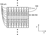
도 1a은, 여러 실시예에서 사용될 수 있는 패터닝된 선형 편광기에서 편광 축을 도시한 도면.
도 1b는, 여러 실시예에서 사용될 수 있는 패터닝된 원형 편광기에서 편광 축을 도시한 도면.
도 2a는, 광이 통과할 수 있도록 정렬된 2개의 패터닝된 선형 편광기를 포함하는 가변 투과율 창을 위한 실시예 장치를 도시한 도면.
도 2b는, 광이 통과할 수 없도록 정렬된 2개의 패터닝된 선형 편광기를 포함하는 가변 투과율 창을 위한 실시예 장치를 도시한 도면.
도 2c는, 일부 광만 통과할 수 있도록 정렬된 2개의 패터닝된 선형 편광기를 포함하는 가변 투과율 창을 위한 실시예 장치를 도시한 도면.
도 3은, 광을 재배향하기 위해 2개의 편광기 사이에 직교 편광 축과 파장판을 갖는 2개의 균일한 편광기를 도시한 도면.
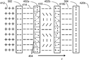
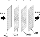
도 4a는, 광이 통과하도록 파장판이 정렬된 2개의 균일한 편광기와 2개의 패터닝된 파장판을 포함하는 가변 투과율 창을 위한 실시예 장치를 도시한 도면.
도 4b는, 광이 통과하지 않도록 파장판이 정렬된 2개의 균일한 편광기와 2개의 패터닝된 파장판을 포함하는 가변 투과율 창을 위한 실시예 장치를 도시한 도면.
도 4c는, 일부 광만 통과하지 않도록 파장판이 정렬된 2개의 균일한 편광기와 2개의 패터닝된 파장판을 포함하는 가변 투과율 창을 위한 실시예 장치를 도시한 도면.
도 5는, 여러 실시예에서 사용하기에 적합한 패터닝된 파장판을 도시한 도면.
도 6은, 여러 실시예에서 사용하기에 적합한 패터닝된 파장판을 도시한 도면.
도 7a ~ 도 7c는, 패터닝된 파장판을 다른 패터닝된 파장판에 대해 선형으로 변위하기 위한 여러 메커니즘을 갖는 가변 투과율 창의 개요도.
도 7d 및 도 7e는, 일정량의 투과 광을 이동시키기 위해 패터닝된 파장 지연판에서 선형 변위를 도시한 도면.
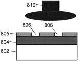
도 8a는 러빙(rubbing)되는 정렬층을 도시하고, 도 8b는 자외선에 블랭킷 노출된 정렬층의 광학 축 변화를 취하는 액정 중합체 층을 도시하며, 도 8c는 패터닝된 포토마스크 아래에서 정렬층의 노출을 도시하는, 도면.
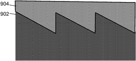
도 9는, 여러 실시예에서 사용하기에 적합한 가변 두께 파장판을 제조하기 위해 사용된 톱니 치형 기판(saw tooth substrate)의 개요도.
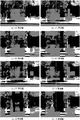
도 10은, 예시적인 실시예에서 광 투과율의 변화 정도를 나타내는 일련의 사진을 도시하는 도면.The accompanying drawings, which are incorporated in and constitute a part of this specification, illustrate embodiments of the invention and, together with the general description given above and the description given below, are used to describe features of the invention.
1A illustrates a polarization axis in a patterned linear polarizer that can be used in various embodiments.
FIG. 1B illustrates a polarization axis in a patterned circular polarizer that can be used in various embodiments. FIG.
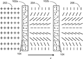
FIG. 2A illustrates an embodiment device for a variable transmittance window that includes two patterned linear polarizers aligned to allow light to pass through. FIG.
FIG. 2B illustrates an embodiment device for a variable transmittance window that includes two patterned linear polarizers aligned such that light cannot pass therethrough. FIG.
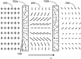
FIG. 2C shows an embodiment arrangement for a variable transmittance window comprising two patterned linear polarizers aligned so that only some light can pass therethrough. FIG.
3 shows two uniform polarizers having an orthogonal polarization axis and a wave plate between the two polarizers to redirect light.
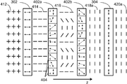
FIG. 4A shows an embodiment device for a variable transmittance window comprising two uniform polarizers and two patterned waveplates aligned with the waveplate to allow light to pass through. FIG.
FIG. 4B shows an embodiment arrangement for a variable transmittance window comprising two uniform polarizers and two patterned waveplates with the waveplates aligned such that no light passes therethrough. FIG.
FIG. 4C shows an embodiment device for a variable transmittance window comprising two uniform polarizers and two patterned waveplates aligned so that only some light passes therethrough. FIG.
5 illustrates a patterned waveplate suitable for use in various embodiments.
6 illustrates a patterned waveplate suitable for use in the various embodiments.
7A-7C are schematic diagrams of a variable transmittance window having various mechanisms for linearly displacing a patterned waveplate with respect to another patterned waveplate.
7D and 7E show linear displacement in a patterned wavelength retardation plate to move a quantity of transmitted light.
FIG. 8A shows the alignment layer being rubbed, FIG. 8B shows the liquid crystal polymer layer taking the optical axis change of the alignment layer blanket exposed to ultraviolet light, and FIG. 8C shows the exposure of the alignment layer under the patterned photomask. Showing the drawing.
9 is a schematic diagram of a saw tooth substrate used to fabricate a variable thickness wave plate suitable for use in various embodiments.
FIG. 10 shows a series of photographs showing the degree of change in light transmittance in an exemplary embodiment. FIG.
여러 실시예가 동반된 도면을 참조하여 상세히 기술될 것이다. 가능한 어디에서나 동일 구성요소를 지칭하기 위해 도면 전체에 걸쳐 동일 참조부호가 사용될 것이다. 특정한 예와 구현에 대한 언급은 예시 목적을 위한 것이며 발명 또는 청구항의 범위를 제한하려는 것이 아니다.Various embodiments will be described in detail with reference to the accompanying drawings. Wherever possible, the same reference numerals will be used throughout the drawings to refer to the same components. Reference to specific examples and implementations is for illustrative purposes and is not intended to limit the scope of the invention or the claims.
"복수"라는 단어는, 본원에서는 2 이상을 의미하기 위해 사용된다. 예를 들어, 복수는 3 이상, 또는 2 ~ 200, 4 ~ 200, 또는 70 ~ 180과 같이 여러 범위를 나타낼 수도 있다.The word "plurality" is used herein to mean two or more. For example, the plurality may represent three or more ranges, or various ranges such as 2 to 200, 4 to 200, or 70 to 180.
여러 실시예는 광 투과율에서 연속적이거나 거의 연속적인 변화를 제공하도록 구성된 가변 광 투과율 장치를 포함한다. 대안적으로, 장치는 "온" 투과 상태 및 광 투과율이 이를테면 1% 이하와 같이 5% 미만인 낮은 투과율 "오프" 또는 어두운 상태와 같은 개별 상태 사이에서 변환할 수 있다. 이들 장치는 건물, 차량, 또는 광, 눈부심, 또는 열을 단속하는 것이 유용할 그외 어떤 다른 장소에서 창(window) 또는 차양과 같이 많은 서로 다른 용도에 사용될 수 있다. 여러 실시예는 편광 및 파장 지연판 이론을 이용한다. 예를 들어, 실시예는 서로에 관하여 선형으로 변위되도록 구성된 2 이상의 균일 또는 패터닝된 광 편광기 또는 파장 지연판을 포함할 수 있다. 또 다른 실시예는 본 명세서에 개시된 여러 방법 중 어느 것에 의해 제조되는 균일 또는 패터닝된 편광기 또는 파장 지연판을 포함할 수 있다. 본원에서 사용되는 바와 같이, "광"이라는 용어는, 적외선 및/또는 자외선(예를 들어, 태양 스펙트럼의 IR 및 UV 부분)뿐만 아니라, 가시선(예를 들어, 태양 스펙트럼의 가시 부분)을 포함한다.Various embodiments include a variable light transmission device configured to provide a continuous or near continuous change in light transmission. Alternatively, the device can switch between individual states, such as "on" transmission states and low transmission "off" or dark states where the light transmittance is less than 5%, such as 1% or less. These devices can be used in many different applications, such as windows or sunshades, in buildings, vehicles, or anywhere else where light, glare, or heat can be useful. Several embodiments use polarization and wavelength retardation theory. For example, embodiments may include two or more uniform or patterned optical polarizers or wavelength retarders configured to be linearly displaced relative to one another. Still other embodiments may include uniform or patterned polarizers or wavelength retardation plates made by any of the various methods disclosed herein. As used herein, the term “light” includes not only infrared and / or ultraviolet (eg, IR and UV portions of the solar spectrum) but also visible (eg, visible portion of the solar spectrum). .
편광 이론Polarization theory
전자기파는 서로 수직이고 파장 전파의 방향으로 진동하는 전계 성분 및 자계 성분을 포함한다. 광 빔은 이의 전파 방향, 주파수, 및 벡터 진폭(예를 들어, 전계 벡터)에 의해 기술될 수 있다. 벡터 진폭은 빔의 세기에 관계되고 파의 진행 방향에 수직이다. 파장 전파의 방향(예를 들어, z-축)이 주어지면, 전계 벡터 진폭의 2개의 독립적인 상호 직교하는 횡 방향 성분인, 정상(ordinary) 광선 및 이상(extraordinary) 광선(예를 들어, Ex와 Ey)이 존재한다.Electromagnetic waves include electric field components and magnetic field components that are perpendicular to each other and oscillate in the direction of wavelength propagation. A light beam can be described by its propagation direction, frequency, and vector amplitude (eg, electric field vector). The vector amplitude is related to the intensity of the beam and is perpendicular to the direction of travel of the wave. Given the direction of wavelength propagation (e.g. the z-axis), two independent mutually orthogonal transverse components of the field vector amplitude are normal and extraordinary rays (e.g. E x and E y ) are present.
전계 벡터 및 전파 방향을 내포하는 평면을 편광 평면이라고 한다. 편광은 파의 진동의 배향을 기술하는 파의 특성이다.The plane containing the electric field vector and the propagation direction is called a polarization plane. Polarization is a characteristic of a wave that describes the orientation of the vibrations of the wave.
무편광 광에서, 전계 벡터는 전파 방향에 관하여 랜덤하게 배향된다. 반대로, 전계 벡터가 모든 파에 대해 동일한 방향으로 배향되면, 광은 평면 편광된 것으로서 간주된다. 편광기는 무편광 광의 빔으로부터 편광된 광의 빔을 생성하는 광학 배열이다. 전파 방향(예를 들어, z-축)이 주어지면, 편광기는 무편광 광의 빔의 전계 벡터를 2개의 독립적인 상호 직교하는 횡 방향 성분인 정상 광선 및 이상 광선(예를 들어, Ex 및 Ey)으로 분해하고 우선적으로 하나를 선택하고 다른 것은 거절한다. 편광기의 유형에 따라, 이 선택은 흡수, 반사, 굴절, 또는 산란에 의해 달성된다.In unpolarized light, the electric field vectors are randomly oriented with respect to the direction of propagation. Conversely, if the electric field vector is oriented in the same direction for all waves, the light is considered to be plane polarized. A polarizer is an optical arrangement that produces a beam of polarized light from a beam of unpolarized light. Given a direction of propagation (e.g., the z-axis), the polarizer has two independent mutually orthogonal transverse components, the normal and abnormal light (e.g., E x and E y ) and preferentially select one and reject the other. Depending on the type of polarizer, this selection is accomplished by absorption, reflection, refraction, or scattering.
말루스의 법칙은 편광기가 입사 빔의 전방에 놓여졌을 때 초래되는 세기(I)를 준다.Malus's law gives the intensity (I) that results when the polarizer is placed in front of the incident beam.
I = IO cos2 θ i I = I O cos 2 θ i
IO는 초기 세기이며 θ i은 광의 초기 편광 방향과 편광기의 축 사이의 각도이다.I 0 is the initial intensity and θ i is the angle between the initial polarization direction of the light and the axis of the polarizer.
무편광 광의 빔은 모든 가능한 각에서 선형 편광의 균일 혼합을 내포하는 것으로서 간주될 수 있다. cos2 θ의 하나의 주기에 대한 적분은 1/2이기 때문에, 단일 편광기를 통하여 투과 광의 세기는 초기 세기의 50%이다. 실제로, 일부 광은 전형적으로 편광기 내에서 손실되고 무편광 광의 실제 투과율은 이보다 다소 낮을 수도 있다.A beam of unpolarized light can be considered as containing a uniform mixture of linearly polarized light at all possible angles. Since the integration over one period of cos 2 θ is 1/2, the intensity of the transmitted light through the single polarizer is 50% of the initial intensity. In fact, some light is typically lost in the polarizer and the actual transmission of unpolarized light may be somewhat lower.
두 개의 선형 편광기가 연이어 놓여졌을 때, 이들의 편광 축 사이에 상호 각은 말루스의 법칙에서 θ의 값을 제공한다. 제 2 편광기는 일반적으로 분해기라고 한다. 그러므로, 편광기의 편광 축과 분해기의 편광 축이 평행할 때 광 투과량은 최대가 되고, 두 축이 직교할 때 편광기는 교차되며 이론적으로 어떠한 광도 투과되지 않는다. 또한, 다른 편광기에 대해 하나의 편광기를 회전시키면 말루스의 법칙에 따라 투과율의 범위에 걸쳐 이의 최대와 최소 사이에서 광을 부분적으로 차단하게 될 것이다.When two linear polarizers are placed in series, the mutual angle between their polarization axes gives the value of θ in Malus' law. The second polarizer is generally referred to as a resolver. Therefore, the amount of light transmission becomes maximum when the polarization axis of the polarizer and the polarization axis of the resolver are parallel, and when the two axes are orthogonal, the polarizers are crossed and theoretically no light is transmitted. In addition, rotating one polarizer relative to the other polarizer will, in accordance with Malus's law, partially block light between its maximum and minimum over a range of transmittances.
파장 wavelength 지연판Retarder 이론 theory
광의 편광을 조작하기 위한 또 다른 유용한 툴은 파장판으로도 알려진 파장 지연판이다. 파장판 또는 지연판은 이를 통해 진행하는 파의 편광 상태를 변경하는 (즉, 파의 편광 축 재배향) 복굴절 물질이다.Another useful tool for manipulating the polarization of light is a wavelength retardation plate, also known as a wave plate. Waveplates or retardation plates are birefringent materials that change the polarization state of a wave propagating through it (ie, reorient the polarization axis of the wave).
복굴절 또는 이중 굴절은 무편광 광의 빔을 2개의 광선으로 분할한다. 대부분의 광학 물질은 등방성인데, 즉, 물질을 통과하는 전파 방향에 관계없이 동일한 광학 특성(및 이에 따라 하나의 굴절률)을 갖는다. 이방성 물질에서, 이웃한 원자 구조 유닛 사이의 분리는 서로 다른 방향에서 서로 다르거나 이러한 유닛을 함께 묶는 결합은 서로 다른 방향에서 서로 다른 특징을 갖는다. 결국, 파의 속도는 변위 방향의 함수이다. 이러한 물질을 통해 전파하는 편광된 광은 전파 및 편광 배향의 서로 다른 방향에 대해 상이한 굴절률을 경험할 것이다. 이 현상은 복굴절로서 알려져 있다. 물질 내에는 이를 따라 전파하는 광이 자신의 편광 방향에 관계없이 단지 하나의 굴절률만 마주치게 하는 고유한 광학 특성을 갖는 광학 축이 존재한다. 복굴절 물질은 이들이 광학 축을 하나만 갖고 있는지 아니면 두 개를 갖는지에 따라, 단축이거나 2축이다. 간략하게 하기 위해서 이하 실시예에서는 단축 물질이 논의될지라도, 여러 실시예는 2 이상의 광학 축을 갖는 복굴절 물질을 포함할 수도 있다.Birefringence or double refraction splits the beam of unpolarized light into two rays. Most optical materials are isotropic, ie they have the same optical properties (and thus one refractive index) regardless of the direction of propagation through the material. In anisotropic materials, the separation between neighboring atomic structural units is different in different directions or the bonds that bind these units together have different characteristics in different directions. After all, the velocity of the wave is a function of the displacement direction. Polarized light propagating through this material will experience different refractive indices for different directions of propagation and polarization orientation. This phenomenon is known as birefringence. Within the material is an optical axis with inherent optical properties such that light propagating along it encounters only one index of refraction regardless of its polarization direction. Birefringent materials are uniaxial or biaxial, depending on whether they have only one or two optical axes. Although uniaxial materials are discussed in the following examples for the sake of simplicity, various embodiments may include birefringent materials having two or more optical axes.
선형으로 편광된 전자기파에 대해 각 전파 방향에 있어서 속도가 상이한 2개의 주요 변위 방향이 있다. 이들 편광 방향은 수직으로 있다. 광빔의 편광 평면이 2개의 주요 변위 방향 중 하나와 일치하지 않을 때, 광 벡터는 두 방향에 대응하는 2개의 성분으로 분할될 것이다. 정상 광선은 이의 전계 벡터가 광학 축에 수직하게 항시 편광되고 정상 굴절률(no)에 접할 때, 굴절의 스넬의 법칙을 따라 모든 방향에서 동일한 속력으로 진행한다. 이상 파는 이의 전계 벡터가 정렬축에 평행하게 항시 편광되고 이상 굴절률(ne)에 접하여, 자신의 파면에 수직으로 전파하지 않으며 일반적으로 스넬의 법칙을 따르지 않는다. 두 광선 사이에서 분리는 광이 결정의 광학 축의 방향에 관하여 결정을 통해 진행하는 방향에 따른다. 정량적으로, 물질의 복굴절 값은 (ne - no)으로서 정의된다.For linearly polarized electromagnetic waves, there are two main displacement directions that differ in speed in each propagation direction. These polarization directions are vertical. When the plane of polarization of the light beam does not coincide with one of the two major displacement directions, the light vector will be divided into two components corresponding to the two directions. The normal ray travels at the same speed in all directions according to Snell's law of refraction when its electric field vector is always polarized perpendicular to the optical axis and abuts the normal refractive index n o . The anomaly wave is not always propagated perpendicularly to its wavefront, its polarity is always polarized parallel to the alignment axis and in contact with the anomaly refractive index n e and generally does not follow Snell's law. The separation between the two rays depends on the direction in which light travels through the crystal relative to the direction of the crystal's optical axis. Quantitatively, the birefringence value of a material is defined as (n e -n o ).
ne > no이면, 이상 파의 전파 속도는 정상 파의 속도보다 크며, 복굴절 물질은 포지티브라고 한다. 그 반대가 성립한다면 복굴절 물질은 네거티브라고 한다. 흔히 가장 큰 인덱스 값을 갖고 전파하는 축을 저속 축이라고 한다.If n e > n o , the propagation velocity of the ideal wave is greater than that of the stationary wave, and the birefringent material is said to be positive. If the opposite is true, the birefringent material is said to be negative. The axis that propagates with the largest index value is often called the slow axis.
간단히 말하면, 복굴절 물질은 서로 다른 속도로 한 가지 유형의 진동이 하나의 경로로 진행하게 하고, 다른 유형이 다른 경로로 진행하게 하여 광을 2개의 성분으로 분해한다. 결국, 성분은 위상을 달리하여 복굴절 물질로부터 나오고 입사광의 편광 상태는 변경된다.In short, the birefringent material causes one type of vibration to travel in one path at a different speed and another type to travel in another path, breaking down the light into two components. As a result, the components come out of the birefringent material at different phases and the polarization state of the incident light is changed.
이상 및 정상 광선에 대한 결과적인 위상차 또는 지연(Γ)은 다음 식으로 주어진다.The resulting phase difference or delay for the ideal and normal rays is given by
Γ = 2πd(ne - no)/λ Γ = 2 π d (n e -n o ) / λ
d는 물질 두께를 나타내며, λ는 파장을 나타내며, ne 및 no는 각각 이상 및 정상 광선의 굴절률이다.d denotes the material thickness, λ denotes the wavelength, and n e and n o are the refractive indices of the ideal and normal light rays, respectively.
앞에서 논의된 바와 같이, 편광기의 편광 축과 분해기의 편광 축이 직교하지 않을 때 광은 투과하지 않는다. 그러나, 편광기와 분해기 사이에 파장판을 삽입시키는 것은 편광된 광의 상태를 변경하며 광이 통과하게 할 수 있다. 파장판의 광학 축이 입력 편광기의 축에 대해 θ의 각으로 교차된 편광기 사이에 놓일 때, 주입된 광의 세기는 다음과 같이 표현된다.As discussed above, light does not transmit when the polarization axis of the polarizer and the polarization axis of the resolver are not orthogonal. However, inserting the waveplate between the polarizer and the resolver can change the state of polarized light and allow the light to pass through. When the optical axis of the waveplate lies between the polarizers crossed at an angle of θ relative to the axis of the input polarizer, the intensity of the injected light is expressed as follows.
I = I0sin22θsin2(Γ/2)I = I 0 sin 2 2 θ sin 2 (Γ / 2)
그러므로, 투과 광의 양은, (1) 인입측 편광기의 광학 축과 파장판의 광학 축 사이의 각 및 (2) 지연 둘 다에 의해 결정된다. 또한, 지연은 복굴절 물질의 두께 및 파장판의 복굴절(ne - no)에 의해 결정된다.Therefore, the amount of transmitted light is determined by both (1) the angle between the optical axis of the incoming polarizer and the optical axis of the waveplate and (2) the delay. The retardation is also determined by the thickness of the birefringent material and the birefringence n e -n o of the waveplate.
지연이 π 라디안(또는 180°)에 대응한다면, 이를 반파장판이라고 한다. Γ = π의 지연은 편광이 입력 편광 평면에 대해 반파장판의 고속 축의 각을 2번 회전하게 할 것이다. 투과 광의 양은 인입측 편광기의 광학 축과 반파장판 사이의 각에 의해 결정된다. 반파장판의 광학 축을 인입측 편광기에 대해 45°에 배치하는 것은 최대 투과율을 달성한다. 반파장판의 광학 축을 입력 또는 출력 편광기의 광학 축의 어느 하나와 정렬시키는 것은 최소 투과율을 준다. 또한, 반파장판의 광학 축의 회전은 말루스의 법칙에 따라 투과율의 범위에 걸쳐 이의 최소와 최대 사이에서 광이 부분적으로 차단되도록 한다.If the delay corresponds to π radians (or 180 °), it is called a half-wave plate. A delay of Γ = π will cause the polarization to rotate twice the angle of the fast axis of the half wave plate with respect to the input polarization plane. The amount of transmitted light is determined by the angle between the optical axis of the incoming polarizer and the half wave plate. Placing the optical axis of the half wave plate at 45 ° relative to the incoming polarizer achieves maximum transmittance. Aligning the optical axis of the half wave plate with either of the optical axes of the input or output polarizer gives the minimum transmission. In addition, the rotation of the optical axis of the half wave plate causes the light to be partially blocked between its minimum and maximum over the range of transmittance according to Malus's law.
여러 실시예는 1/4-파장판을 포함할 수도 있다. 1/4-파장판은 π/2 라디안(또는 90°)의 지연 또는 1/4-파장 위상 이동을 가지며 선형으로 편광된 광을 원형으로 편광되고 다시 그 반대로 변경할 수 있다.Various embodiments may include a quarter-wave plate. The quarter -wave plate may have a delay of π / 2 radians (or 90 °) or a quarter-wave phase shift and linearly polarized light to be circularly polarized and vice versa.
또한, 지연을 조절함으로써 광 투과율을 가변하는 것이 가능하다. 가변 지연판의 고속 축을 소정의 각, 이를테면 45°또는 입력 편광기에 관하여 또 다른 적합한 각에 정렬시키고, 반파 및 전파장(full wave) 사이의 지연을 조절함으로써, 투과율은 최대와 최소 사이에서 가변한다. 이러한 지연 변화는 복굴절 물질의 두께 또는 막의 복굴절(ne - no)을 가변함으로써 달성될 수 있다.It is also possible to vary the light transmittance by adjusting the delay. By aligning the high speed axis of the variable retardation plate to a predetermined angle, such as 45 ° or another suitable angle with respect to the input polarizer, and adjusting the delay between half wave and full wave, the transmittance varies between maximum and minimum. . This delay change can be achieved by varying the thickness of the birefringent material or the birefringence n e -n o of the film.
가변 투과율 창Variable transmittance window
여러 실시예는 패터닝된 편광기 또는 패터닝된 파장판을 선형으로 변위시켜 조절 가능한 가변 투과율 창을 포함한다. 패터닝된 편광기 또는 파장판은 또 다른 패터닝된 편광기 또는 파장판에 대해 이동할 수 있다. 일부 실시예에서, 편광기 및 파장판은 다른 편광기 또는 파장판에 관하여 함께 이동하게 패널 내에 함께 결합될 수도 있다. 예를 들어, 일부 실시예는 제 2 파장판에 제 2 균일 선형 편광기가 물리적으로 결합된 제 2 패널에 관하여 선형으로 변위할 수 있는, 제 1 균일 선형 편광기 및 제 1 파장판이 함께 물리적으로 결합된 제 1 패널을 포함할 수 있다. 대안적으로, 하나 또는 두 파장판은 패널 또는 편광기에 연결되지 않을 수도 있다.Various embodiments include a variable transmittance window that is adjustable by linearly displacing the patterned polarizer or patterned waveplate. The patterned polarizer or waveplate can move relative to another patterned polarizer or waveplate. In some embodiments, the polarizer and the waveplate may be coupled together within the panel to move together with respect to other polarizers or waveplates. For example, some embodiments provide that the first uniform linear polarizer and the first wavelength plate are physically coupled together, which may be linearly displaced relative to a second panel that is physically coupled to the second wavelength plate. It may comprise a first panel. Alternatively, one or both waveplates may not be connected to the panel or polarizer.
실시예는 여러 유형의 편광기를 포함할 수 있다. 일부 실시예는 단일 균일한 편광 축을 갖는 균일한 편광기를 탑재할 수도 있다. 이들 편광기는 요오드 염색된 편광기, 와이어 그리드 편광기, 코팅 가능 편광기, 반사형 편광기, 또는 각종의 흡수형 편광기를 포함할 수 있다. 대안 실시예는 다수의 편광 축을 갖는 패터닝된 편광기를 포함할 수 있다. 패터닝된 편광기를 갖는 이들 실시예에 있어서, 파장 지연판은 요구되지 않는다.Embodiments may include several types of polarizers. Some embodiments may mount a uniform polarizer having a single uniform polarization axis. These polarizers may include iodine dyed polarizers, wire grid polarizers, coatable polarizers, reflective polarizers, or various absorbing polarizers. Alternative embodiments may include patterned polarizers having multiple polarization axes. In these embodiments with a patterned polarizer, no wavelength retardation plate is required.
도 1a는 여러 실시예에서 사용될 수 있는 패터닝된 편광기를 도시한 것이다. 패터닝된 편광기(102)는 서로 다른 편광 축을 갖는 여러 영역(104)으로 분할될 수 있다. 도 1a에서 영역(104)의 축은 화살표로 표시되었다. 편광 축은 각 영역 내에서 균일할 수 있지만 이웃 영역 사이에서 가변할 수 있다. 이들 편광 축은 도 1a에 도시된 바와 같이 이웃 영역(104)에 걸쳐 점진적으로 옮겨지게 선택될 수도 있다. 이들 영역(104)은 패터닝된 편광기(102) 위 및 밑에 점으로 나타낸 바와 같이 필요한 만큼 연속되고 반복될 수 있다. 패터닝된 편광기(102)는 크기가 가변할 수 있다. 각 영역(104)은 스트립 형상일 수 있고 폭은 일부 실시예에서 대략 2mm과 같이 1 ~ 10mm일 수 있지만 이 폭은 가변할 수 있다.1A illustrates a patterned polarizer that can be used in various embodiments.
도 1a는 패터닝된 선형 편광기를 도시한 것이다. 대안적으로, 패터닝된 원형 편광기(106)는 도 1b에 도시된 바와 같이 원형 편광 영역(108)을 포함할 수 있다. 패터닝된 선형 편광기(102)와 유사하게, 패터닝된 원형 편광기(106)는 크기가 가변하며 이웃 영역(108)에 걸쳐 점진적으로 옮겨가는 편광 축을 포함할 수 있다. 다음 예는 간단하게 하기 위해서 선형 편광기를 사용하여 제시되지만 다른 실시예는 패터닝된 원형 편광기(106)를 포함할 수도 있다.1A shows a patterned linear polarizer. Alternatively, patterned
여러 실시예에서, 두 선형 편광기의 편광 축은 2개의 균일 선형 편광기가 서로 회전할 때 발생하는 것과 유사하게 다른 편광기에 대해 편광기의 선형 변위가 광 투과율의 연속된 변화가 생기도록 패터닝될 수 있다. 다른 패터닝된 편광기에 대해 패터닝된 편광기의 변위는 이들의 편광 축 사이에 상호 각을 변경하여 말루스의 법칙에서 θ의 값을 주며 따라서 광 투과율을 결정한다. 광 투과율은 패터닝된 편광기의 영역이 얼마나 정렬되었는가에 기초하여 가변할 수 있는데, 이에 따라 편광기가 서로에 상대적으로 얼마나 선형 변위되는지를 기초로 가변할 수 있다.In various embodiments, the polarization axis of the two linear polarizers can be patterned such that the linear displacement of the polarizer with respect to other polarizers results in a continuous change in light transmittance, similar to what happens when two uniform linear polarizers rotate with each other. The displacement of the patterned polarizer relative to the other patterned polarizer changes the mutual angle between their polarization axes to give the value of θ in Malus's law and thus determine the light transmittance. The light transmittance may vary based on how aligned the areas of the patterned polarizer are, and thus may vary based on how linearly the polarizers are displaced relative to each other.
도 2a는 2개의 패터닝된 선형 편광기(102a, 102b){제 2 편광기(102b)는 위에 논의된 바와 같이 분해기라 칭할 수도 있다}의 실시예 배열을 도시한 것이다. 2개의 패터닝된 선형 편광기(102a, 102b)는 서로 다른 편광 축을 갖는 영역(104a ~ 104h)을 포함한다. 광은 z축으로 전파하여 밑에 도시된 z축을 따라 좌에서 우로 편광기를 통과할 수 있다. 광(202)은 원래는 무편광된 것으로 x 및 y 축에 성분을 내포할 수 있다. 도 2a에서 원래의 광(202)의 플러스 기호는 단지 예시를 위해서 x 및 y 성분을 기호로 나타낸 것이지만, 광은 실제로는 z축으로 이동하고 있고, 이에 따라, 이들 성분은 이 관점에서는 이러한 식으로 보이지 않을 것이다. 도 2a에는 편광기 사이에 광(204)과 두 편광기 후에 광(206)이 이들의 x 및 y 편광 배향에 대한 기호로 나타내어져 있지만 z축으로 이동할 수 있다.FIG. 2A shows an embodiment arrangement of two patterned
제 1 패터닝된 편광기(102a)는 도 1a에 편광기(102)와 유사하게 편광 축을 포함할 수 있다. 이들 축은 도 1a에서와 같이 x 및 y 축으로 나타내었지만, 편광기(102a)는 광이 z축을 따라 진행할 수 있게 z축에 수직한 평면에서 90도로 회전된다. 제 2 편광기(102b)는 유사하게 배열될 수 있다. 영역(104a ~ 104h)은 임의의 횟수로 반복할 수 있지만, 간략성을 위해 단일 시리즈만 도시되었다. 도시된 시리즈는 도 2b와 도 2c에서와 같이 편광기가 위 또는 아래로 옮겨질 때 변경될 수 있다.The first
광(202)이 제 1 편광기(102a)를 통과할 때, 광이 통과하는 어느 영역이든 이의 편광 축에 따라 광(202)의 성분이 차단되기 때문에 광은 편광될 수 있다. 결과는 가변적으로 편광된 광(204)일 수 있다. 예를 들어, 편광기(102a)에 보인 맨 위에 영역{즉, 영역(104a)}은 y축으로 편광 배향을 갖고, 이에 따라, x 축에 성분을 차단한다. 따라서, 편광기의 영역(104a)을 따라가는 가변적으로 편광된 광(204)은 x 성분이 없어지게 된다. 다른 영역(104b ~ 104h)도 마찬가지로 각 편광 축에 따라 인입 광(202)의 x와 y 성분을 차단할 수 있다. 이에 따라, 가변적으로 편광된 광(204)은 편광기(102a)의 영역에 따라 가변할 수 있다. 가변적으로 편광된 광(204)의 전체 세기는 말루스의 법칙 및 편광에 관하여 위에 논의된 바와 같이 원래의 광에 대략 반이거나 미만일 수 있다.When light 202 passes through
가변적으로 편광된 광(204)은 제 2 편광기(102b)를 통과할 수 있다. 도 2a에서, 제 2 편광기(102b)는 각 영역이 제 1 편광기(102a) 내 대응하는 영역과 동일한 편광 축을 갖도록 {예를 들어, 제 1 편광기(102a)의 영역(104a)은 제 2 편광기(102b)의 영역(104a)과 정렬되고, 제 1 편광기(102a)의 영역(104b)은 제 2 편광기(102b)의 영역(104b)과 정렬되는 등} 정렬된다. 가변적으로 편광된 광(204)의 각 레벨은 제 1 편광기(102a)에서 통과될 때와 동일한 편광 축을 갖는 영역을 통과할 수 있다. 평행한 편광 축을 갖는 제 2 편광기를 통과하는 것은 말루스의 법칙에 따라 어떠한 추가의 광도 차단하지 않을 수 있다. 그러므로, 최종의 광(206)은 가변적으로 편광된 광(204)과 동일할 수 있다(또는 거의 같을 수 있다). 이것은 가변 광학 투과율 장치의 밝은 상태에 대응한다.Variablely polarized light 204 may pass through
도 2b는 직교 편광 축을 갖는 영역이 정렬되도록 제 2 편광기(102b)가 제 1 편광기(102a)에 관하여 선형으로 변위되는 것을 제외하고, 도 2a와 유사한 실시예를 도시한 것이다. 예를 들어, 제 2 편광기는 몇몇 영역의 폭의 거리만큼 위 또는 아래로 옮겨져 있을 수 있다 {예를 들어, 제 1 편광기(102a)의 영역(104a)은 제 2 편광기(102b)의 영역(104e)과 정렬되고, 제 1 편광기(102a)의 영역(104b)는 제 2 편광기(102b)의 영역(104f)과 정렬되며, 등등}. 가변적으로 편광된 광(204)의 각 레벨은 제 1 편광기(102a)에서 이미 통과된 영역의 편광 축에 직교하는 편광 축을 갖는 영역에 가해 수 있다. 결과는 어떠한 광(206)도 (또는 거의 어느 것도) 제 2 편광기를 통과하지 않는 것일 수 있다. 이것은 가변 광학 투과율 장치의 어두운 상태에 대응한다.FIG. 2B illustrates an embodiment similar to FIG. 2A, except that the
도 2c는 제 1 및 제 2 편광기의 대응하는 영역이 평행하지도 직교하지도 않게 제 2 편광기(102b)가 선형으로 변위되는 것을 제외하고, 또 다른 유사한 실시예를 도시한 것이다. 결과는 일부 광(206)이 제 2 편광기(102b)를 통과하는 것이다. 그러므로, 편광기를 선형으로 변위하여 (즉, 편광기 중 하나를 위 또는 아래로 이동하는), 실시예는 편광기를 통하여 투과 광의 세기를 가변할 수 있게 한다. 또한, 투과되는 통과된 광은 변위량에 기초하여 연속적으로 가변될 수 있다. 편광기는 투과 광의 세기를 연속적으로 가변하기 위해서 서로에 관하여 여러 다른 중간 위치까지 변위될 수 있다. 이것은 가변 광학 투과율 장치의 중간 상태에 대응한다.FIG. 2C illustrates another similar embodiment except that the
대안 실시예는 파장 지연판을 포함할 수 있다. 도 3은 제 1 편광기(302)와 제 2 편광기(304) 사이에 파장 지연판(306)을 도시한 것이다. 앞에 도면과 달리, 제 1 및 제 2 편광기는 서로 다른 편광 축의 영역을 갖게 패터닝되지 않고 편광기 전체에 걸쳐 단일 편광 축(양끝에 화살표를 갖는 실선으로 나타내었다)을 갖게 균일할 수 있다. 제 1 편광기의 편광 축이 제 2 편광기의 편광 축에 직교한다면, 말루스의 법칙에 따라 보통은 어떠한 광도 통과하지 않을 것이다. 그러나, 도 3은 파장 지연판(306)이 다른 결과에 이르게 할 수 있음을 도시한다.Alternative embodiments may include wavelength retardation plates. 3 shows the
광(202)과 유사한 기호를 사용하여 도시된 무편광 광(312)은 제 1 균일한 편광기(302)를 통해 전파할 수 있다. 결과는 y축으로 편광된 광(314)일 수 있다. 편광된 광(314)은 파장 지연판(306)을 통과할 수 있다. 파장 지연판(306)은 복굴절 물질로 만들어지고 따라서 광학 축 또는 축(양끝에 화살표을 갖는 점선으로 나타낸 바와 같이)의 배향에 따라 광을 지연시킨다. 결과는, 편광된 광(314)이 다른 방향으로 편광을 갖는 광(316)으로 재배향될 수 있다는 것이다. 예를 들어, 파장 지연판(306)이 반파장판(즉, π의 지연)이고 편광된 광(314)이 광학 축(즉, 점선)에 관하여 45도의 각(즉, θ)의 편광 축을 갖는다면, 재배향된 광(316)은 광(314)의 원래의 편광 축에 대해 90도의 새로운 편광 축(즉, 2θ)을 가질 것이다. 재배향된 광(316)은 제 2 편광기(304)를 통과할 수 있다. 재배향된 광(316)의 편광이 제 2 균일한 편광기(304)의 편광 축과 평행하다면, 광(318)은 통과할 수 있다.Unpolarized light 312 shown using symbols similar to light 202 can propagate through first
일정량의 투과 광을 연속적으로 가변하기 위해서, 여러 실시예는 광 투과율의 변화를 제어하기 위해서 2개의 균일 선형 편광기 사이 내에 놓인 2개의 패터닝된 파장 지연판에 의존할 수 있다. 패터닝된 파장 지연판은 양을 변화시켜 광을 재배향하는 여러 영역을 가질 수 있다. 다른 패터닝된 지연판에 대해 패터닝된 지연판의 변위는 광의 편광 상태를 변경하며 얼마나 많은 광이 제 2 편광기를 통과할 것인지를 제어할 수 있다.In order to continuously vary the amount of transmitted light, various embodiments may rely on two patterned wavelength retardation plates placed between two uniform linear polarizers to control the change in light transmission. The patterned wavelength retardation plate may have several regions that vary in amount to redirect light. The displacement of the patterned retardation plate relative to the other patterned retardation plate changes the polarization state of the light and can control how much light will pass through the second polarizer.
서로 다른 여러 유형의 파장 지연판이 실시예에서 사용될 수 있다. 파장 지연판은 서로 다른 특징을 갖는 여러 영역을 포함하도록 패터닝될 수 있다. 2개의 교차된 균일 선형 편광기(이를 테면 도 3에 도시된) 사이에 파장 지연판이 배치될 때, 투과되는 되는 광의 양은 (1) 제 1 편광기의 편광 축과 파장 지연판의 광학 축 사이에 각 및 (2) 지연 둘 다에 의해 결정된다. 또한, 지연은 복굴절 물질의 두께와 물질의 복굴절(이상 및 정상 광선의 굴절률 사이의 차이(ne-no)에 의해 결정된다. 결국, 패터닝된 지연판은 이들 3개의 파라미터 중 임의의 하나 이상을 조절함으로써 구성될 수 있다.Different types of wavelength retardation plates may be used in the embodiments. The wavelength retardation plate can be patterned to include several regions with different characteristics. When the wavelength retardation plate is disposed between two crossed uniform linear polarizers (such as shown in FIG. 3), the amount of light transmitted is (1) the angle between the polarization axis of the first polarizer and the optical axis of the wavelength retardation plate. (2) determined by both delay. In addition, the retardation is determined by the thickness of the birefringent material and the birefringence of the material (the difference between the refractive indices of the ideal and normal rays (n e -n o ). It can be configured by adjusting.
일부 실시예에서, 파장 지연판은 파장 지연판의 서로 다른 영역에서 광학 축의 배향을 변화시켜 패터닝된 될 수 있다. 명시된 수의 개별적인 투과율 레벨을 가져오게 할 지연판에서, 두 패터닝된 지연판은 명시된 수의 지연 구역 또는 영역을 포함할 수 있다. 이들 지연 구역은 각각의 지연판 상에 동일한 폭을 가질 수도 있다. 파장 지연판의 광학 축의 배향은 표준 각 차이(예를 들어, 0.1 내지 30도, 이를테면 2 ~ 10도)만큼 이웃 구역의 광학 축의 배향과 서로 다를 수 있다. 대안적으로, 파장 지연판은 하나의 지연판 또는 지연판을 갖는 패널을 제 2 지연판 또는 패널에 관하여 선형으로 변위할 때 광 투과율에 있어 순조롭고 연속된 변경을 제공하도록 구성될 수 있다. 하나의 패널은 다른 패널이 정지한 동안 이동하거나, 변위 동안 두 패널이 이동할 수 있다.In some embodiments, the wavelength retardation plate can be patterned by varying the orientation of the optical axis in different regions of the wavelength retardation plate. In a retardation plate that will result in a specified number of individual transmittance levels, the two patterned retardation plates may comprise a specified number of retardation zones or regions. These delay zones may have the same width on each delay plate. The orientation of the optical axis of the wavelength retardation plate may differ from the orientation of the optical axis of the neighboring zone by a standard angular difference (eg, 0.1 to 30 degrees, such as 2 to 10 degrees). Alternatively, the wavelength retardation plate may be configured to provide a smooth and continuous change in light transmittance when linearly displacing one retardation plate or panel having a retardation plate with respect to the second retardation plate or panel. One panel may move while the other panel is stationary, or two panels may move during displacement.
도 4a는 2개의 균일한 교차된 편광기(302, 304) 사이에 2개의 패터닝된 파장 지연판(402a, 402b)을 갖는 실시예를 도시한 것이다. 대안 실시예에서는 교차되지 않은 편광기가 사용될 수 있으나, 어두운 상태와 밝은 상태는 반대로 될 것이다. 이 실시예에 도시된 2개의 패터닝된 파장 지연판(402a, 402b)은 광학 축 배향{영역(404a ~ 404h)에서 점선의 배향에서 변화에 의해 나타낸 바와 같은}이 변하는 영역(404a ~ 404h)을 포함한다. 그러나, 대안 실시예는 영역의 두께 또는 복굴절을 가변시킴으로써 지연을 가변할 수 있다.4A illustrates an embodiment with two patterned
무편광 광(412)은 제 1 균일한 편광기(302)를 통과할 수 있고 y 방향으로 편광된 광(414)이 된다. 편광된 광(414)은 제 1 패터닝된 파장 지연판(402a)을 통과하고 가변적으로 재배향된 광(416)으로 나타날 수 있다. 가변적으로 재배향된 광(416)은 제 2 패터닝된 파장 지연판(402b)을 통과하고 균일하게 재배향된 광(418a)이 될 수 있다. 균일하게 재배향된 광(418a)은 재배향된 광(418a)이 제 2 균일한 편광기(304)를 통과할 수 있게 제 2 균일한 편광기(304)의 편광 축에 평행한 공통의 편광을 가질 수 있다. 제 2 편광기(304)를 통과하는 광(420a)은 편광된 광(414)과 세기가 대략 동일하거나 미만일 수 있다. 이것은 가변 광학 투과율 장치의 밝은 상태에 대응한다.Unpolarized light 412 may pass through first
도 4b는 제 2 패터닝된 파장 지연판(402b)이 제 1 패터닝된 파장 지연판(402a)에 관하여 선형으로 변위되는 (즉, 위 또는 아래로 옮겨진) 실시예를 도시한 것이다. 도 4a와 유사하게, 무편광 광(412)은 제 1 균일한 편광기(302)을 통과하여 편광된 광(414)이 될 수 있다. 편광된 광(414)은 제 1 패터닝된 파장 지연판(402a)을 통과하고 가변적으로 재배향된 광(416)으로서 나타날 수 있다. 가변적으로 재배향된 광(416)은 제 2 패터닝된 파장 지연판(402b)을 통과하고 재배향된 광(418b)이 될 수 있다. 그러나, 도 4a에서 재배향된 광(418a)과는 달리, 선형으로 변위된 패터닝된 파장 지연판(402b) 후에 재배향된 광(418b)은 제 2 편광기(304)의 편광 축에 직교하게 편광될 수 있고, 따라서 실시예를 통해 투과되는 되는 광(420b)은 없을 수 있다. 이것은 가변 광학 투과율 장치의 어두운 상태에 대응한다.4B illustrates an embodiment in which the second patterned
도 4c는 제 2 패터닝된 파장 지연판(402b)이 제 1 패터닝된 파장 지연판(402a)에 관하여 선형으로 변위되는 (즉, 위 또는 아래로 옮겨진) 또 다른 실시예를 도시한 것이다. 제 2 패터닝된 파장 지연판(402b)은 도 4b에 제 2 패터닝된 파장 지연판의 반만큼 변위될 수 있다. 덜한 변위의 결과는 광의 일부가 제 2 편광기를을 통하여 빛난다는 것이다. 무편광 광(412)은 제 1 균일한 편광기(302)을 통과하고 편광된 광(414)이 될 수 있다. 편광된 광(414)은 제 1 패터닝된 파장 지연판(402a)을 통과하고 가변적으로 재배향된 광(416)으로서 나타날 수 있다. 가변적으로 재배향된 광(416)은 제 2 패터닝된 파장 지연판(402d)을 통과하고 재배향된 광(418c)이 될 수 있다. 재배향된 광(418c)의 편광은 제 2 균일한 편광기(304)의 편광 축에 평행하지도 직교하지도 않을 수 있고, 따라서 광 전부는 아니지만 일부는 420c를 통과한다. 이것은 가변 광학 투과율 장치의 중간 상태에 대응한다.4C illustrates another embodiment in which the second patterned
패터닝된 편광기의 변위와 유사하게, 투과 광은 파장 지연판 사이에 상대적 변위량에 기초하여 연속적으로 가변될 수 있다. 패터닝된 파장 지연판은 투과 광의 세기를 연속적으로 가변하기 위해서 서로에 관하여 여러 중간 위치까지 변위될 수 있다. 패터닝된 파장 지연판의 상대적 선형 변위는 영역(404a ~ 404h)의 정렬을 변경하는데, 이것은 광(418)의 편광을 변경하며 얼마나 많은 광이 제 2 편광기(304)를 통과하는지를 변경한다.Similar to the displacement of the patterned polarizer, the transmitted light can be continuously varied based on the relative amount of displacement between the wavelength retardation plates. The patterned wavelength retardation plates can be displaced up to several intermediate positions with respect to each other to continuously vary the intensity of the transmitted light. The relative linear displacement of the patterned wavelength retardation plate changes the alignment of the regions 404a-404h, which changes the polarization of the light 418 and how much light passes through the
또 다른 실시예의 패터닝된 파장판은 도 4a ~ 도 4c에 도시된 것보다 많은 영역을 포함할 수 있다. 예를 들어, 도 5는 32개의 영역에 1 ~ 32의 번호가 매겨진 예시적인 패터닝된 파장판(502)을 도시한 것이다. 도 5의 패터닝된 반파장판(502)은 32개의 동일 폭 영역으로 구성되고 이들에 있어 지연판의 광학 축의 배향은 이웃한 영역(예를 들어, 선으로 나타낸 바와 같이, 총 180°) 사이에서 5.625°의 스텝 크기만큼 변경된다. 대안 실시예는 이외 여러 다른 개수의 영역 및 각도 스텝 크기를 갖는 파장판을 포함할 수 있다.The patterned waveplate of another embodiment may include more regions than shown in FIGS. 4A-4C. For example, FIG. 5 illustrates an example patterned
도 4a ~ 도 4c 및 도 5의 패터닝된 파장 지연판은 점진적으로 변하는 광학 축 배향이 영역에서 아크 또는 U 형상의 패턴을 제공할 수 있음을 도시한 것이다. 이 패턴은 영역이 반복할 때 반복될 수 있다. 도 6은 많은 영역에서 U 형상 패턴의 여러 세트(604)를 갖는 예시적인 패터닝된 파장판(602)을 도시한 것이다. 각 세트(604)는 도 5에 도시된 32개의 영역을 포함한다.The patterned wavelength retardation plates of FIGS. 4A-4C and 5 show that progressively changing optical axis orientation can provide an arc or U-shaped pattern in the region. This pattern can be repeated as the region repeats. 6 illustrates an example patterned
위에 논의된 패터닝된 편광기 또는 파장 지연판의 선형 변위는 여러 방법으로 달성될 수 있다. 상대적 위치가 투과율을 결정하기 때문에, 하나 또는 두 패터닝된 편광기 또는 파장판은 이동될 수도 있다. 대안 실시예에서, 패터닝된 편광기 또는 파장 지연판은 패터닝된 편광기 또는 파장 지연판을 서로에 관하여 안내하기 위해 슬라이딩 메커니즘에, 이를테면 레일을 따라, 부착될 수 있다. 패터닝된 편광기 또는 파장 지연판을 변위하기 위해 여러 다른 기계식 장치이 사용될 수도 있다.The linear displacement of the patterned polarizer or wavelength retarder discussed above can be achieved in several ways. Since the relative position determines the transmittance, one or two patterned polarizers or waveplates may be moved. In alternative embodiments, the patterned polarizer or wavelength retardation plate may be attached to a sliding mechanism, such as along a rail, to guide the patterned polarizer or wavelength retardation plate with respect to each other. Various other mechanical devices may be used to displace the patterned polarizer or wavelength retardation plate.
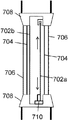
일부 실시예에서, 패터닝된 편광기 또는 파장 지연판의 변위는 전자적으로 제어될 수 있는데, 이를테면 컴퓨터 또는 각종의 로직 회로에 의해 자동으로 제어되거나 또는 사용자로부터 지시들에 의해 수동적으로 제어될 수 있다(예를 들어, 사용자는 디밍 스위치를 누른다). 도 7a는 이러한 기계식 장치를 갖는 가변 광 투과율 창 실시예를 도시한 것이다. 유리 또는 또 다른 투명한 물질의 플레이트(706)는 벽 또는 그외 다른 표면 내 프레임(708) 내에 고정될 수 있다. 윈도우 플레이트(706) 사이에, 2개의 편광기(704)가 프레임 내에 고정될 수도 있다. 2개의 파장판(702a, 702b)은 편광기(704) 사이에 놓일 수 있다. 도 7a에서, 하나의 파장판(702b)은 프레임(708)에 고정되고 제 2 파장판(702a)은 일 단부에서 메커니즘(710)에 결합된다. 제 2 파장판(702a)의 다른 단부는 프레임(708)에 의해 이동 가능하게 지지될 수 있다. 메커니즘(710)은 다른 파장판(702b)에 관하여 파장판(702a)을 선형으로 옮기기 위한 여러 장치를 포함할 수 있다. 예를 들어, 메커니즘(710)은 여러 전동식, 전기기계식, 자기, 또는 압전 장치, 또는 전기 신호를 선형 변위로 변환할 수 있는 기타 임의의 장치 중 임의의 것을 포함할 수 있다.In some embodiments, the displacement of the patterned polarizer or wavelength retardation plate may be electronically controlled, such as automatically controlled by a computer or various logic circuits or manually controlled by instructions from a user (eg For example, the user presses the dimming switch). 7A illustrates a variable light transmission window embodiment with such a mechanical device.
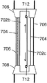
대안 실시예에서, 패터닝된 편광기 또는 파장 지연판은 패터닝된 편광기 또는 파장 지연판을 위 또는 아래로 이동시키기 위해 끝에 회전 지지부에 감겨질 수 있다. 이들 편광기 또는 파장 지연판은 선형으로 변위하기 위해 위쪽 또는 아래쪽으로 감길 수 있다. 도 7b는 이러한 회전 지지부를 갖는 가변 광 투과율 창 실시예를 도시한 것이다. 유리 또는 또 다른 투명한 물질의 플레이트(706)는 벽 또는 그외 다른 표면 내 프레임(708) 내에 고정될 수 있다. 윈도우 플레이트(706) 사이에는 2개의 편광기(704)이 프레임 내에 고정될 수도 있다. 2개의 파장판(702b, 702c)은 편광기(704) 사이에 놓일 수 있다. 하나의 파장판(702)은 프레임(708)에 고정되고 제 2 파장판(702b)은 각 단부에서 회전 지지부(712)에 결합된다. 이들 회전 지지부(712)는 유연한 파장판(702c)을 다른 파장판에 관하여 위쪽 또는 아래쪽으로 감을 수 있다. 회전 지지부(712)는 도 7a에 관하여 기술된 바와 같이 수동으로(예를 들어, 사용자는 노브를 돌린다) 또는 자동으로 회전될 수 있다.In an alternative embodiment, the patterned polarizer or wavelength retardation plate may be wound around the rotary support at the end to move the patterned polarizer or wavelength retardation plate up or down. These polarizers or wavelength retarders can be wound up or down for linear displacement. FIG. 7B shows an embodiment of a variable light transmission window having such a rotational support.
도 7c는 두 파장판(702d, 702e)이 회전 장치(714)에 의해 동시에 이동되는 대안 실시예를 도시한 것이다. 파장판(702d, 702e)은 회전 스풀 또는 릴(714) 둘레에 장착되는 하나의 연속된 파장판 막 또는 웹(web)의 부분일 수 있다. 이들 회전 장치(714)는 위에 기술된 바와 같이 수동으로 또는 자동으로 회전될 수 있다.FIG. 7C shows an alternative embodiment in which two
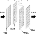
도 7d 및 도 7e는 제 2 패터닝된 파장 지연판(702b)에 관하여 제 1 패터닝된 파장 지연판(702a)의 선형 변위를 도시한 것이다. 파장 지연판(702a, 702b)은 2개의 교차된 균일한 편광기(704) 사이에 있을 수 있다. 도 7d는 광이 투과될 수 있게 하는 변위된 지연판(702a)을 도시한 것이다. 도시된 바와 같이, 파장 지연판(702a)은 다른 파장 지연판(702b)에 관하여 영역의 크기에 따르는 요망되는 양만큼 선형으로 변위될 수 있다(예를 들어, 도 7d에 도시된 바와 같이 수직으로). 예를 들어, 변위 거리는 도면에 도시된 13mm와 같이 5 내지 50 mm일 수 있는데, 이 거리는 영역의 폭과 수에 따라 가변할 수 있다. 도 7e는 역으로 선형으로 변위되고 (예를 들어, 수직 아래로) 광이 장치를 투과하지 못하도록 하는 지연판(702a)을 도시한 것이다. 수직 선형 변위가 도시되었지만, 선형 변위는 수평 방향, 또는 장치의 성분이 위치한 것에 기초하여 그라운드에 관하여 수직과 수평 사이의 그외 어떤 다른 방향으로 있을 수 있음에 유의한다.7D and 7E illustrate the linear displacement of the first patterned
도면에 도시된 실시예는 편광기와 파장 지연판 사이에 갭을 포함하는데, 그러나 이것은 일부 실시예에서 회피될 수도 있을 것이다. 예를 들어, 파장 지연판은 적층되거나 편광기에 고정될 수 있다. 일부 실시예는 편광기 및/또는 파장판을 내장할 수 있는 패널을 포함할 수 있다. 이들 패널은 서로 변위될 수 있다. 또 다른 실시예에서, 편광기 또는 패널은 고정된 상태로 있을 수 있고, 편광기 또는 패널 사이에 하나 이상의 파장 지연판은 선형으로 변위된다.The embodiment shown in the figures includes a gap between the polarizer and the wavelength retardation plate, but this may be avoided in some embodiments. For example, the wavelength retardation plate may be laminated or fixed to the polarizer. Some embodiments may include a panel that may contain a polarizer and / or a wave plate. These panels can be displaced from one another. In yet another embodiment, the polarizer or panel may be stationary and one or more wavelength retardation plates are linearly displaced between the polarizer or panel.
여러 실시예는 몇 가지 서로 다른 방법 중 어느 것에 의해 제작된 패터닝된 파장 지연판 또는 편광기를 포함할 수 있다. 한 가지 제조 방법에서, 패터닝된 지연 막을 생성하기 위해서 기판(또는 편광기)에 적층될 수 있는 다수 스트립의 회전 축 지연 필터를 생성하기 위해 연신된 중합체 지연 막은 서로 다른 배향에서 여러 크기의 스트립으로 절단될 수 있다.Various embodiments may include a patterned wavelength retarder or polarizer fabricated by any of several different methods. In one manufacturing method, the stretched polymer retardation film is cut into strips of different sizes in different orientations to produce multiple strip rotational axis retardation filters that can be laminated to a substrate (or polarizer) to produce a patterned retardation film. Can be.
다른 제조 방법에서, 지연판의 광학 축의 배향의 변경은 정렬층의 기계식 러빙을 통해 달성될 수 있다. 도 8a에 도시된 바와 같이, 통상의 정렬층(804)이 기판(802) 상에 피착될 수 있다. 마스크(805)는 정렬층 상에 놓여지고 이어서 마스크(805) 내 개구(806)를 통해 노출된 층(804)의 부분에 특정 정렬을 유발시키 위해 연마륜(810)으로 러빙된다. 이어서, 샘플은 다른 마스크를 사용하여 다른 방향으로 러빙될 수 있다. 이 방법은 마스크를 사용하지 않고 수행될 수도 있다. 마스크(805)가 제거된 후에, 도 8b에 도시된 바와 같이 층(804) 내에 러빙 패턴을 따르는 층(806) 내에 패터닝된 지연판을 생성하기 위해 액정 중합체(806)가 층(804)의 표면 상에 피착되고 방사선(예를 들어, 자외선)(808)에 블랭킷 노출된다. 액정 중합체(806)는 정렬층(806)에 러빙된 배향을 채택하고 패터닝된 파장판(즉, 지연판)이 된다.In another manufacturing method, the change of the orientation of the optical axis of the retardation plate can be achieved through mechanical rubbing of the alignment layer. As shown in FIG. 8A, a
다른 제조 방법에서, 지연판의 광학 축의 배향의 변경은 액정 중합체의 광패터닝된 표면 정렬을 통해 달성될 수도 있다. 정렬층은 정렬 표면에 접촉한 액정(LC) 분자의 명료한 배향을 제공한다. 광정렬된 층은 광 노출에 의해서만, 즉, 어떠한 기계적 접촉도 없이 배향되고, 결국 임의의 배향이 LC 분자에 이전될 수 있게 한다. 전용의 광-반응성 중합체(아조-염료, 롤릭 리서치 선형 광중합체)가 코팅된 기판을 선형으로 편광된 UV광(LPUV)에 노출시키는 것은 편광 방향으로 우선적 정렬 방향 및 이어서 광반응성 정렬층과 접촉하는 LC 분자의 정렬을 유발한다. 정렬 방향에 공간적 변화는 정렬층을 상이하게 조정된 LPUV 광에 구역 선택적으로 노출시킴으로써, 즉 세기, 입사각, 또는 편광 방향을 가변하여 유발될 수 있다. 제 2 단계에서, 이방성 LPP 층은 광개시제 또한 함유하는 액정 중합체(LCP)의 제형이 코팅된다. 하지의 LPP 층에 의해 LCP를 정렬시킨 후에, 막은 무편광 UV광으로 가교되어 영속적으로 배향된 패터닝된 지연판을 제공한다.In other manufacturing methods, a change in the orientation of the optical axis of the retardation plate may be achieved through photopatterned surface alignment of the liquid crystal polymer. The alignment layer provides a clear orientation of the liquid crystal (LC) molecules in contact with the alignment surface. The photoaligned layer is oriented only by light exposure, ie without any mechanical contact, which in turn allows any orientation to be transferred to the LC molecule. Exposing a substrate coated with a dedicated photo-reactive polymer (azo-dye, Rollic Research linear photopolymer) to linearly polarized UV light (LPUV) is in contact with the preferred alignment direction in the polarization direction and then with the photoreactive alignment layer. Causes alignment of the LC molecules. Spatial changes in the alignment direction can be caused by zone-selective exposure of the alignment layer to differently adjusted LPUV light, ie by varying the intensity, angle of incidence, or polarization direction. In a second step, the anisotropic LPP layer is coated with a formulation of liquid crystal polymer (LCP) that also contains a photoinitiator. After aligning the LCP by the underlying LPP layer, the film is crosslinked with unpolarized UV light to provide a permanently oriented patterned retardation plate.
LPP에서 정렬 패턴을 발생하는 서로 다른 방법이 있다. 이들 중에는 포토마스크, 정렬 마스터, 레이저 스캐닝 및 동기화된 회전의 사용 및/또는 UV-노출 동안 UV-편광기 및 기판의 이동이 있다. 단일 노출 단계로 요구되는 복잡한 정렬 패턴을 생성하기 위한 한 가지 선택은 정렬 마스터의 사용이다. 정렬 마스터의 기능은 공간적 변화의 편광 평면에 LPUV 광을 제공하는 것으로, 이것은 광이 LPP 층에 가해질 때 정렬 패턴을 곧바로 발생한다.There are different ways to generate alignment patterns in LPP. Among these are the use of photomasks, alignment masters, laser scanning and synchronized rotation and / or movement of UV-polarizers and substrates during UV-exposure. One choice for creating the complex alignment pattern required by a single exposure step is the use of an alignment master. The function of the alignment master is to provide LPUV light in the spatially varying polarization plane, which immediately generates an alignment pattern when light is applied to the LPP layer.
포토마스크를 통해 UV 광을 사용하여 준비되는 정렬층의 예가 도 8c에 도시되었다. 정렬층(804)이 기판(802) 상에 피착될 수 있다. UV 선(808)은 편광기(817)를 통과하여 편광된 UV 선이 될 수 있다. 이어서, 결과적인 편광된 UV 선은 패터닝된 포토마스크(815)를 통과하여 정렬층(804)의 부분을 선택적으로 노출시킨다. 이것은 노출된 정렬층(804) 내에 패턴을 생성한다. 이 프로세스는 정렬층(804)에 관하여 포토마스크(815)를 이동하고/이동하거나 복수의 포토마스크(815)를 통해 정렬층(804)을 노출시켜 전체 정렬층(804)을 패터닝함으로써 반복될 수 있다. 이어서, 액정 중합체 층은 패터닝된 정렬층(804) 상에 피착되고 액정 중합체 층을 중합하기 위해 블랭킷 노출된다. 액정 중합체 층은 정렬층(806)에 패터닝된 배향을 채택하고, 패터닝된 파장판(즉, 지연판)(도 8b에 도시된 프로세스와 유사한)이 된다.An example of an alignment layer prepared using UV light through a photomask is shown in FIG. 8C.
다른 제조 방법에서, 지연판의 광학 축의 배향의 변경은 격자 구조 상에 액정 중합체 패터닝을 통해 달성된다. 패터닝된 지연판은 기판 상에 패터닝된 격자-유사 톱니 표면을 사용하여 생성될 수도 있다. 이들 격자 구조는 평탄한 기판 상에 포토레지스트를 피착하고 진폭 포토마스크를 통해 노출시킴으로써 생성된다. 일반적인 섀도우 포토마스크 대신, 진폭 포토마스크는 개별적 지역에 대조되는 매끄러운 특징부(feature)가 생기도록 하는 투과율의 변화도이다. 진폭 마스크를 통해 포토레지스트를 노광하고 현상하는 것은 기판 상에 톱니 패턴을 생성한다. 이 기판 상에 액정 중합체를 코팅하는 것은 교번하는 액정 중합체 정렬을 생성하며 이에 따라 톱니 상에 위치에 따라 교번하는 지연 값을 생성한다.In another manufacturing method, the change of the orientation of the optical axis of the retardation plate is achieved through liquid crystal polymer patterning on the lattice structure. The patterned retardation plate may be created using a grating-like tooth surface patterned on a substrate. These grating structures are created by depositing photoresist on a flat substrate and exposing through an amplitude photomask. Instead of a typical shadow photomask, an amplitude photomask is a variation in transmittance that results in smooth features contrasting to individual regions. Exposing and developing the photoresist through an amplitude mask creates a sawtooth pattern on the substrate. Coating the liquid crystal polymer on this substrate produces an alternating liquid crystal polymer alignment and thus an alternating delay value depending on position on the tooth.
다른 제조 방법에서, 지연판의 광학 축의 배향의 변경은 인쇄 가능 자기-조립 유기물/리오트리픽(lyotropic) 액정을 통해 달성된다. 자기-조립 거동을 나타내는 유기 분자는 지연판에서 필요한 복굴절 특성을 나타낸다. 이들 자기-조립 유체는 연신된 중합체 지연막보다 저렴한 지연 필터를 형성하기 위해 기판 상에 코팅 또는 인쇄될 수 있다. 타원 (이방성) 분자의 장축의 정렬은 슬롯-다이 인쇄 프로세스를 통해 야기된 압력에 의해 결정된다. 지연판의 광학 축의 서로 다른 배향은 전단력의 방향을 가변시킴으로써 달성될 수 있다.In another manufacturing method, the change of orientation of the optical axis of the retardation plate is achieved through printable self-assembly organic / lyotropic liquid crystal. Organic molecules exhibiting self-assembly behavior exhibit the necessary birefringent properties in the retardation plate. These self-assembled fluids may be coated or printed onto the substrate to form a delay filter that is less expensive than the stretched polymer delay film. The alignment of the long axis of the elliptic (anisotropic) molecule is determined by the pressure caused through the slot-die printing process. Different orientations of the optical axis of the retardation plate can be achieved by varying the direction of shear force.
여러 실시예에서, 파장 지연판은 복굴절 물질의 두께를 변경함으로써 패터닝될 수 있다. 특정 수의 개별 투과율 레벨을 야기할 막에 대해서, 2개의 패터닝된 지연판은 동일 폭의 특정 수의 지연하는 구역을 포함할 것이다. 파장 지연판의 두께는 표준 개별적 양만큼 이웃 구역의 두께와는 다르다. 하나의 패널을 제 2 패널에 대해 선형으로 변위하면 광 투과율이 순조롭고 연속적으로 변경되도록 할 막을 제작하는 것 또한 가능하다. 복굴절 물질의 두께를 변경함으써 패터닝된 된 가변 지연판은 다음 방법에 의해서 또는 유사한 방법에 의해 제작될 수 있다.In various embodiments, the wavelength retardation plate can be patterned by varying the thickness of the birefringent material. For membranes that will result in a certain number of individual transmission levels, the two patterned retarders will contain a certain number of retarding zones of the same width. The thickness of the wavelength retardation plate differs from the thickness of the neighboring zone by standard individual quantities. It is also possible to produce a film that will displace one panel linearly with respect to the second panel so that the light transmittance is smooth and continuously changed. The variable retarder patterned by varying the thickness of the birefringent material can be fabricated by the following method or by a similar method.
한 가지 제조 방법에서, 지연에 변화는 액정 중합체 지연 층의 두께 패터닝을 통해 달성된다. 액정 중합체는 기판 상에 습식으로 코팅되어 균일 정렬층이 기판 상에 코팅된다. 특정 지역을 평면의 정렬로 광중합하기 위해 UV 포토마스크 노출이 사용된다. 이어서, 가교 및 중합체되지 않은 액정 중합체를 용해하기 위해서 기판은 테트라하이드로퓨란(또는 이외 다른 현상액)으로 처리된다. 이것은 지연이 전혀 없는 지역과 액정 중합체 복굴절 및 층 두께에 따른 지연의 지역이 되도록 한다.In one manufacturing method, the change in retardation is achieved through the thickness patterning of the liquid crystal polymer retardation layer. The liquid crystal polymer is wet coated on the substrate so that a uniform alignment layer is coated on the substrate. UV photomask exposure is used to photopolymerize a particular area in a planar alignment. The substrate is then treated with tetrahydrofuran (or other developer) to dissolve the crosslinked and unpolymerized liquid crystal polymer. This allows for areas of no retardation and areas of retardation depending on the liquid crystal polymer birefringence and layer thickness.
다른 제조 방법에서, 파장 지연판은 복제 몰드 액정 중합체 인쇄를 통해 복굴절 물질의 두께를 변경함으로써 패터닝된다. PDMS(polydimethylsiloxane) 중합체 몰드 스탬프는 마스터 사진식각적으로 제작된 중합체 몰드를 사용하여 생성되고, 이어서 중합 액정에 패턴을 스탬프하기 위해 사용될 수 있다. 액정 중합체는 스탬프가 물질 내 인쇄되어 경화되어 잔류된 패터닝된 액정 지연판을 남긴다. 정렬은 추가의 정렬층이 필요하지 않도록 액정 중합체를 처리된 인쇄하는 PDMS 표면과 상호작용함으로써 발생된다.In another manufacturing method, the wavelength retardation plate is patterned by changing the thickness of the birefringent material through replica mold liquid crystal polymer printing. PDMS (polydimethylsiloxane) polymer mold stamps are produced using a master photoetched polymer mold and can then be used to stamp the pattern on the polymerized liquid crystal. The liquid crystal polymer is stamp printed in the material and cured leaving a patterned liquid crystal retardation plate remaining. Alignment occurs by interacting the liquid crystal polymer with the treated printing PDMS surface so that no additional alignment layer is needed.
다른 제조 방법에서, 파장 지연판은 표면 높이를 가변시키면서 기판 상에 물질을 코팅하는 것을 통해 복굴절 물질의 두께를 변경함으로써 패터닝된다. 표면 높이를 가변시키기 위해서, 마이크로-엠보싱 방법이 제시된다. 이 방법은 마이크로 패터닝된 스탬프 및 폴리에틸렌(PET) 폴리비닐 알코올(PVA) 또는 폴리이미드와 같은 몰딩 가능 비-복굴절 투명 기판으로 구성된다. 이어서, 이 패터닝된 기판은 몰드로부터 벗겨지고 인쇄 가능 중합 액정 또는 그외 다른 복굴절 물질이 코팅된다.In another manufacturing method, the wavelength retardation plate is patterned by varying the thickness of the birefringent material through coating the material on the substrate while varying the surface height. In order to vary the surface height, a micro-embossing method is presented. The method consists of a micro patterned stamp and a moldable non-birefringent transparent substrate such as polyethylene (PET) polyvinyl alcohol (PVA) or polyimide. This patterned substrate is then peeled from the mold and coated with a printable polymeric liquid crystal or other birefringent material.
앞에 방법을 위한 몰드의 예가 도 9에 도시되었다. 스탬프 또는 기판(902)은 여러 형상으로 높이가 가변할 수 있다. 도 9에서 기판(902)은 톱니 형상의 예를 예시한다. 액정 중합체(904)는 가변하는 두께 및 지연을 취하기 위해 몰드(902) 상에 적층될 수 있다.An example of a mold for the method is shown in FIG. 9 above. The stamp or
일부 실시예에서, 파장 지연판은 복굴절을 변경함으로써 패턴닝된다. 특정 수의 개별 투과율 레벨을 일으킬 막에서, 2개의 패터닝된 지연판은 동일 폭의 특정 수의 지연되는 구역을 포함할 것이다. 파장 지연판의 복굴절은 표준 개별적 양만큼 이웃 구역의 복굴절과는 다르다. 하나의 패널을 제 2 패널에 대해 선형으로 변위하면 광 투과율이 순조롭고 연속적으로 변경되도록 할 막을 제작하는 것 또한 가능하다. 복굴절 물질의 두께를 변경함으로써 패터닝된 된 가변 지연판은 다음 방법에 의해서 또는 유사한 방법에 의해 제작될 수 있다.In some embodiments, the wavelength retardation plate is patterned by changing the birefringence. In a membrane that will result in a certain number of individual transmission levels, the two patterned retarders will comprise a certain number of retarded zones of the same width. The birefringence of the wavelength retardation plate differs from the birefringence of the neighboring zone by a standard individual amount. It is also possible to produce a film that will displace one panel linearly with respect to the second panel so that the light transmittance is smooth and continuously changed. The variable retardation plate patterned by changing the thickness of the birefringent material can be manufactured by the following method or by a similar method.
한 가지 제조 방법에서 파장 지연판은 액정 중합체의 열적 패터닝을 통해 복굴절을 변경함으로써 패터닝된다. 패터닝된 지연판은 액정 중합체를 사용하여 생성되고 표준 균일 정렬층이 코팅될 수 있다. 액정 아크릴레이트는 기판 상에 습식으로 코팅되고 정렬층에 따른 평면의 구성으로 배향되도록 한다. 포토마스크가 생성되고 액정 중합체는 선택된 지역에서 평면의 정렬을 가교하여 고정시키기 위해 UV광에 노출된다. 포토마스크가 제거되고 샘플은 액정 중합체 녹는 점 이상으로 가열된다(등방성 또는 랜덤한 정렬 조건을 생성한다). 이어서, 샘플은 선형 조건에서 이전에 중합되지 않은 지역에서 랜덤한 정렬을 고정하기 위해 블랭킷 노출된다. 두 노출은 UV 노출의 부재시 중합 및 포토마스크 경계 밖에서 가교 중합을 최소화하기 위해 질소 환경에서 수행된다.In one manufacturing method, the wavelength retardation plate is patterned by changing the birefringence through thermal patterning of the liquid crystal polymer. The patterned retardation plate can be produced using a liquid crystal polymer and coated with a standard uniform alignment layer. The liquid crystal acrylate is wet coated onto the substrate and is oriented in a planar configuration along the alignment layer. A photomask is created and the liquid crystal polymer is exposed to UV light to crosslink and fix the alignment of the planes in the selected area. The photomask is removed and the sample is heated above the liquid crystal polymer melting point (creating isotropic or random alignment conditions). The sample is then blanket exposed to fix the random alignment in areas that were not previously polymerized in linear conditions. Both exposures are carried out in a nitrogen environment to minimize crosslinking polymerization outside the photomask boundary and polymerization in the absence of UV exposure.
다른 제조 방법에서, 파장 지연판은 액정 중합체 및 광반응성 이성질체의 광패터닝을 통해 복굴절을 변경함으로써 패터닝된다. 위에 방법에서와 같이 등방성에 온도를 증가시킴으로써 액정 정렬을 제거하기보다는, 노출을 통해 등방성 온도를 수정하기 위해 액정 중합체와 광반응성 이성질체와의 혼합체가 사용될 수 있다. 구성은 이미 피착된 선형 정렬층을 갖는 기판 상에 액정 중합체가 코팅되는 점에서 유사하다. 이어서, 액정 중합체 혼합체는 포토마스크를 통해 노출되지만, 그러나 이들 지역에서 액정 중합체를 중합하는 대신, 액정 중합체 혼합체의 하나의 성분의 이성질체화를 통해 등방성 온도를 변경한다. 시스템은 UV 노출시, 등방성 전이 온도가 실온 미만으로 감소되도록 설계된다. 결국, 제 1 노출 단계에서 노출된 지역은 등방성 정렬을 가지며 노출되지 않은 지역은 선형 구성인 채로 있는다. 이어서, 막을 고형화하기 위해 제 2 블랭킷 노출이 수행된다.In another manufacturing method, the wavelength retardation plate is patterned by altering birefringence through photopatterning of the liquid crystal polymer and the photoreactive isomer. Rather than removing the liquid crystal alignment by increasing the temperature to isotropic as in the above method, a mixture of liquid crystal polymers and photoreactive isomers may be used to modify the isotropic temperature through exposure. The configuration is similar in that the liquid crystal polymer is coated onto a substrate having a linear alignment layer already deposited. The liquid crystal polymer mixture is then exposed through a photomask, but instead of polymerizing the liquid crystal polymer in these areas, the isotropic temperature is changed through the isomerization of one component of the liquid crystal polymer mixture. The system is designed such that upon UV exposure, the isotropic transition temperature is reduced below room temperature. As a result, the exposed areas in the first exposure step have an isotropic alignment and the unexposed areas remain in a linear configuration. Subsequently, a second blanket exposure is performed to solidify the film.
다른 제조 방법에서, 광반응성 정렬층(예를 들어, 롤릭 LPP)을 직접 액정 중합체 혼합체(표면 상에 코팅하고 액정 중합체를 도포하기 전에 패터닝하는 것과는 반대로)에 혼합하는 것을 통해 복굴절을 변경함으로써 파장 지연판이 패터닝된다. 이 기술에서, 액정 중합체의 정렬은 단지 표면에서만이 아니나 액정 중합체 혼합체의 볼륨 전체에 걸쳐 제어된다. 이 혼합체는 균일한 평면의 정렬층을 갖는 기판에 도포된다. 샘플은 하나의 UV 편광을 갖는 하나의 지역과 다른 편광을 갖는 다른 지역에서 노출된 UV 포토마스크이다. 서로 다른 편광 노출은 서로 다른 키랄성(좌수, 우수)을 갖는 나선형 또는 트위스트된 액정 중합체 구조를 생성하는데, 이에 따라 서로 다른 양의 지연을 야기한다.In another manufacturing method, the wavelength retardation is achieved by altering the birefringence through mixing the photoreactive alignment layer (e.g., L. LPP) directly into the liquid crystal polymer mixture (as opposed to coating on the surface and patterning before applying the liquid crystal polymer). The plate is patterned. In this technique, the alignment of the liquid crystal polymer is controlled not only at the surface but throughout the volume of the liquid crystal polymer mixture. This mixture is applied to a substrate having a uniform alignment layer. The sample is a UV photomask exposed in one area with one UV polarization and another area with another polarization. Different polarization exposures produce helical or twisted liquid crystal polymer structures with different chirality (left hand, rainwater), resulting in different amounts of delay.
다른 제조 방법에서, 파장 지연판은 광정렬된 콜레스테릭 액정을 통해 복굴절을 변경함으로써 패터닝된다. 콜레스테릭 액정(CLC)은 DNA의 구조와 유사한 나선형 또는 트위스트된 구조를 갖는다. 어떤 CLC은 키랄성(또는 나선형 트위스팅 파워)의 양이 UV 광 노출 투여를 통해 조절될 수 있게, 예를 들어, UV에 대한 오랜 노출이 트위스트를, 이에 따라 CLC의 지연을 조절할 수 있게 조작될 수 있다. 패터닝된 지연층은 다수의 포토마스크를 통해 UV 광의 서로 다른 투여량에 CLC의 서로 다른 영역을 노출하여 형성될 수도 있다.In another manufacturing method, the wavelength retardation plate is patterned by changing the birefringence through the photoaligned cholesteric liquid crystal. Cholesteric liquid crystals (CLCs) have a helical or twisted structure similar to that of DNA. Some CLCs can be manipulated such that the amount of chirality (or helical twisting power) can be controlled through the administration of UV light exposure, for example, that long exposure to UV can control the twist and thus the delay of the CLC. have. The patterned retardation layer may be formed by exposing different regions of the CLC to different doses of UV light through multiple photomasks.
다른 제조 방법에서, 파장 지연판은 중합 연신된 지연판을 레이저 인쇄하는 것을 통해 복굴절을 변경함으로써 패터닝된다. 복굴절은 형상 이방성 및 이에 따른 복굴절/지연을 유발하는 중합체의 연신을 통해 중합체 막에 도입된다. 이들 중합체막의 가열 또는 화학적 처리는 스트레스가 가해진 중합체 결합을 끊을 수 있어 국부화된 구역에서 단량체의 랜덤한 정렬을 생성할 수 있다. 이것은 레이저가 적합한 투여량를 전달하게 잘 제어된다면 레이저 인쇄 프로세스를 통해 패터닝된 지연막을 생성하기 위해 이용될 수 있다. 레이저는 샘플에 걸쳐 스캐닝되고 국부적 가열을 통해 인쇄된 스트립에 지연을 제거한다.In another manufacturing method, the wavelength retardation plate is patterned by changing the birefringence through laser printing the polymer stretched retardation plate. Birefringence is introduced into the polymer membrane through stretching of the polymer causing shape anisotropy and thus birefringence / delay. Heating or chemical treatment of these polymer membranes can break stressed polymer bonds, resulting in random alignment of monomers in the localized zone. This can be used to produce a patterned retardation film through a laser printing process if the laser is well controlled to deliver a suitable dosage. The laser is scanned across the sample and eliminates delay in the printed strip through local heating.
다른 제조 방법에서, 파장 지연판은 가변하는 복굴절을 갖는 서로 다른 액정 물질의 스트립을 코팅하는 것을 통해 복굴절을 변경함으로써 패터닝된다. 이 방법에서, 슬롯 다이 코팅기는 기판에 걸쳐 서로 다른 구역에서 서로 다른 액정 물질을 피착할 것이다.In other manufacturing methods, the wavelength retardation plate is patterned by changing the birefringence through coating strips of different liquid crystal materials having varying birefringence. In this method, the slot die coater will deposit different liquid crystal materials in different regions across the substrate.
패터닝된 지연판을 생성하기 위해 위에 명시된 방법 또는 유사한 방법의 어느 것의 조합이 사용될 수 있는 것 또한 가능하다.It is also possible that any combination of the above or similar methods can be used to produce the patterned retardation plate.
도 10은 발명의 실시예의 가변 투과율 장치를 통과하는 광의 예시적 실시예를 시사하는 일련의 디지털 이미지이다. 이미지(a) ~ 이미지(h)는 파장 지연판이 서로에 관하여 선형으로 변위될 때 광 투과율의 변화를 보여준다. 각 이미지는 가변 투과율 장치가 위치하는 중앙 부분을 내포한다. 이미지(a)는 중앙 부분을 통해 광의 38% 투과율을 보여주는 것으로 배경에서 물체가 명확하게 보여질 수 있다. 각 이미지에서 중앙 부분은 이미지(h)가 중앙 부분을 통해 1% 광 투과율을 보일 때까지 점진적으로 어두워진다(즉, 각각 이미지(b) 내지 이미지(g)의 중앙에서 35%, 30%, 20%, 13%, 7%, 4% 투과율).10 is a series of digital images suggesting an exemplary embodiment of light passing through the variable transmittance device of the embodiment of the invention. Image (a) to (h) show the change in light transmittance when the wavelength retardation plates are linearly displaced with respect to each other. Each image contains a central portion where the variable transmittance device is located. Image (a) shows a 38% transmission of light through the central part so that the object can be clearly seen in the background. In each image, the central portion gradually darkens until image h exhibits 1% light transmission through the central portion (i.e. 35%, 30%, 20 at the center of image b to image g, respectively). %, 13%, 7%, 4% transmittance).
개시된 양상의 상기 설명은 당업자가 본 발명을 제작 또는 사용할 수 있도록 하기 위해 제공된다. 이러한 양상에 대한 여러 변형예는 당업자에게 쉽게 분명해질 것이고 본 명세서에 정의된 일반 원리는 발명의 범위 내에서 다른 양상에 적용될 수도 있다. 이에 따라, 본 발명은 본 명세서에 제시된 양상에 제한되도록 의도되지 않고, 본 명세서에 개시된 원리와 신규 특징에 일치하는 가장 넓은 범위에 따르도록 의도된다.The previous description of the disclosed aspects is provided to enable any person skilled in the art to make or use the present invention. Various modifications to this aspect will be readily apparent to those skilled in the art, and the generic principles defined herein may be applied to other aspects within the scope of the invention. Accordingly, the present invention is not intended to be limited to the aspects set forth herein but is to be accorded the widest scope consistent with the principles and novel features disclosed herein.
Claims (23)
제 1 편광 축을 갖는 제 1 균일한 편광기(polarizer)와,
제 2 편광 축을 갖는 제 2 균일한 편광기와,
상기 제 1 편광기와 상기 제 2 편광기 사이에 위치하고, 광학 축, 두께, 또는 복굴절 중 적어도 하나가 가변하도록 구성된 제 1 복수의 영역을 포함하는, 제 1 패터닝된 파장 지연판(wave retarder)과,
상기 제 1 편광기와 상기 제 2 편광기 사이에 위치하고, 광학 축, 두께, 또는 복굴절 중 적어도 하나가 가변하도록 구성된 제 2 복수의 영역을 포함하는, 제 2 패터닝된 파장 지연판을
포함하고,
상기 제 1 또는 제 2 파장 지연판은, 상기 제 1 또는 제 2 파장 지연판 중 다른 것에 대해 선형으로 변위될 수 있도록 구성된, 가변 투과율 장치.In a variable transmission device,
A first uniform polarizer having a first polarization axis,
A second uniform polarizer having a second polarization axis,
A first patterned wave retarder, positioned between the first polarizer and the second polarizer, and including a first plurality of regions configured to vary at least one of an optical axis, thickness, or birefringence;
A second patterned wavelength retardation plate positioned between the first polarizer and the second polarizer and including a second plurality of regions configured to vary at least one of an optical axis, thickness, or birefringence
Including,
And the first or second wavelength retardation plate is configured to be linearly displaced relative to the other of the first or second wavelength retardation plate.
제 1 편광기와,
제 2 편광기와,
상기 제 1 편광기와 상기 제 2 편광기 사이에 위치하고, 광학 축의 배향이 가변하도록 구성된 제 1 복수의 영역을 포함하는, 제 1 패터닝된 파장 지연판와,
상기 제 1 편광기와 상기 제 2 편광기 사이에 위치하고, 광학 축의 배향이 가변하도록 구성된 제 2 복수의 영역을 포함하는, 제 2 패터닝된 파장 지연판을
포함하고,
상기 제 1 또는 제 2 파장 지연판은 상기 제 1 또는 제 2 파장 지연판 중 다른 것에 대해 선형으로 변위될 수 있게 구성된, 가변 투과율 장치.In the variable transmittance device,
A first polarizer,
With a second polarizer,
A first patterned wavelength retardation plate, positioned between the first polarizer and the second polarizer, and including a first plurality of regions configured to vary an orientation of an optical axis;
A second patterned wavelength retardation plate, positioned between the first polarizer and the second polarizer, and including a second plurality of regions configured to vary the orientation of the optical axis;
Including,
And the first or second wavelength retardation plate is configured to be linearly displaced relative to the other of the first or second wavelength retardation plate.
상기 제 1 편광기는 제 1 편광 축을 갖는 균일 선형이고,
상기 제 2 편광기는 제 2 편광 축을 갖는 균일 선형이며,
상기 제 1 편광 축과 상기 제 2 편광 축은 평행하지 않고,
상기 장치는 벽에 설치된 제 1 윈도우 플레이트와 제 2 윈도우 플레이트 사이에 위치한, 가변 투과율 장치.18. The method of claim 17,
The first polarizer is uniform linear with a first polarization axis,
The second polarizer is uniform linear with a second polarization axis,
The first polarization axis and the second polarization axis are not parallel,
And the device is located between a first window plate and a second window plate mounted on a wall.
상기 가변 광학 투과율 장치를 통해 광이 덜 투과되도록 상기 제 1 패터닝된 파장 지연판을 상기 제 2 패터닝된 파장 지연판에 대해 이동시키는 단계와,
상기 가변 광학 투과율 장치를 통해 광이 더 많이 투과되도록 상기 제 1 패터닝된 파장 지연판을 상기 제 2 패터닝된 파장 지연판에 대해 이동시키는 단계를
포함하는, 장치 작동 방법.A method of operating the device of claim 1,
Moving the first patterned wavelength retardation plate relative to the second patterned wavelength retardation plate so that less light is transmitted through the variable optical transmission device;
Moving the first patterned wavelength retardation plate relative to the second patterned wavelength retardation plate such that more light is transmitted through the variable optical transmission device.
Comprising, the device operating method.
정렬층을 내포하는 기판을 제공하는 단계와,
패터닝된 정렬층을 생성하기 위해 상기 정렬층을 방사선에 노출하는 단계와,
액정 중합체 층을 상기 패터닝된 정렬층 상에 피착하는 단계와,
가변 광학 축을 갖는 상기 패터닝된 파장 지연판을 형성하기 위해 상기 액정 중합체 층이 상기 패터닝된 정렬층의 패턴을 채택하도록 상기 액정 중합체 층을 중합하는 단계를
포함하는, 패터닝된 파장 지연판 제조 방법.A method of making a patterned wavelength retardation plate for a variable transmission window,
Providing a substrate containing an alignment layer,
Exposing the alignment layer to radiation to produce a patterned alignment layer;
Depositing a liquid crystal polymer layer on the patterned alignment layer;
Polymerizing the liquid crystal polymer layer such that the liquid crystal polymer layer adopts a pattern of the patterned alignment layer to form the patterned wavelength retardation plate having a variable optical axis.
A method for manufacturing a patterned wavelength retardation plate, comprising.
Applications Claiming Priority (3)
| Application Number | Priority Date | Filing Date | Title |
|---|---|---|---|
| US201061428307P | 2010-12-30 | 2010-12-30 | |
| US61/428,307 | 2010-12-30 | ||
| PCT/US2011/067754 WO2012092443A2 (en) | 2010-12-30 | 2011-12-29 | Variable transmission window |
Publications (1)
| Publication Number | Publication Date |
|---|---|
| KR20130137668A true KR20130137668A (en) | 2013-12-17 |
Family
ID=46380475
Family Applications (1)
| Application Number | Title | Priority Date | Filing Date |
|---|---|---|---|
| KR20137019900A KR20130137668A (en) | 2010-12-30 | 2011-12-29 | Variable transmission window |
Country Status (8)
| Country | Link |
|---|---|
| US (2) | US8508681B2 (en) |
| EP (1) | EP2659298A4 (en) |
| JP (2) | JP6292879B2 (en) |
| KR (1) | KR20130137668A (en) |
| CN (1) | CN103384841B (en) |
| CA (1) | CA2861759A1 (en) |
| HK (1) | HK1191101A1 (en) |
| WO (1) | WO2012092443A2 (en) |
Cited By (1)
| Publication number | Priority date | Publication date | Assignee | Title |
|---|---|---|---|---|
| WO2019107906A1 (en) * | 2017-11-28 | 2019-06-06 | 주식회사 엘지화학 | Variable transmittance device and use thereof |
Families Citing this family (54)
| Publication number | Priority date | Publication date | Assignee | Title |
|---|---|---|---|---|
| US9871594B2 (en) | 2012-01-23 | 2018-01-16 | Vg Smartglass, Llc | Mechanical translation of a variable radiation transmission device |
| US9671538B2 (en) | 2012-11-19 | 2017-06-06 | The Arizona Board Of Regents On Behalf Of The University Of Arizona | Optical elements comprising cholesteric liquid crystal polymers |
| TWI540346B (en) * | 2012-12-31 | 2016-07-01 | Lg化學股份有限公司 | Optical device |
| TWI536054B (en) * | 2013-05-30 | 2016-06-01 | 明基材料股份有限公司 | Dimming device |
| TWI522660B (en) * | 2013-05-30 | 2016-02-21 | 明基材料股份有限公司 | Polarizer for dimming device |
| KR20150007518A (en) * | 2013-07-11 | 2015-01-21 | 동우 화인켐 주식회사 | Liquid crystal panel and liquid crystal display devices comprising the same |
| US9562388B2 (en) | 2013-07-24 | 2017-02-07 | Corning Incorporated | Methods of forming polarized panes for variable transmission windows |
| WO2015033932A1 (en) * | 2013-09-03 | 2015-03-12 | 富士フイルム株式会社 | Optical filter and optical-filter-equipped display device |
| JP2015099362A (en) * | 2013-10-15 | 2015-05-28 | 日東電工株式会社 | Optical layered body and dimming window |
| KR101641139B1 (en) * | 2013-10-16 | 2016-07-29 | 주식회사 엘지화학 | A Master Mold for Smart Window Capable of Continuous Change of Transmission, the manufacturing Method of the Same and Film for Smart Window using The Same |
| JP5854179B2 (en) * | 2014-01-24 | 2016-02-09 | 大日本印刷株式会社 | Light control sheet and light control plate |
| WO2015111562A1 (en) * | 2014-01-24 | 2015-07-30 | 大日本印刷株式会社 | Dimming sheet and dimming panel |
| TWI468729B (en) * | 2014-02-06 | 2015-01-11 | Benq Materials Corp | Light switching module |
| TWI468731B (en) * | 2014-02-06 | 2015-01-11 | Benq Materials Corp | Light switching module |
| CN103885173B (en) * | 2014-03-13 | 2016-07-13 | 明基材料有限公司 | Light switching module |
| WO2015162553A1 (en) | 2014-04-22 | 2015-10-29 | Politecnico Di Milano | Interactive device for the selective control of electromagnetic radiation |
| US20150378168A1 (en) * | 2014-05-19 | 2015-12-31 | Smartershade, Inc. | Patterned image device |
| JP6379663B2 (en) * | 2014-05-19 | 2018-08-29 | 大日本印刷株式会社 | Light control device and space partition structure |
| JP5954636B2 (en) * | 2014-07-25 | 2016-07-20 | 大日本印刷株式会社 | Light control device and method of installing the light control device |
| JP6418488B2 (en) * | 2014-08-07 | 2018-11-07 | 大日本印刷株式会社 | Light control device and method of installing the light control device |
| JP2016045466A (en) * | 2014-08-26 | 2016-04-04 | 大日本印刷株式会社 | Light adjustment device and installation method of light adjustment device |
| JP6375791B2 (en) * | 2014-09-02 | 2018-08-22 | 大日本印刷株式会社 | Light control device |
| JP2016136205A (en) * | 2015-01-23 | 2016-07-28 | 大日本印刷株式会社 | Optical control panel and installation method of optical control panel |
| JP6492836B2 (en) * | 2015-03-23 | 2019-04-03 | 大日本印刷株式会社 | Film material for light control device, plate material for light control device, light control device |
| JP6613594B2 (en) * | 2015-04-03 | 2019-12-04 | 大日本印刷株式会社 | Light control device |
| US10254454B2 (en) | 2015-06-15 | 2019-04-09 | Magic Leap, Inc. | Display system with optical elements for in-coupling multiplexed light streams |
| KR102346728B1 (en) * | 2015-06-30 | 2022-01-04 | 삼성디스플레이 주식회사 | Display apparatus |
| JP2017026686A (en) * | 2015-07-16 | 2017-02-02 | 富士フイルム株式会社 | Dimmer |
| JP6496629B2 (en) * | 2015-07-23 | 2019-04-03 | 富士フイルム株式会社 | Light control device |
| WO2017022591A1 (en) * | 2015-07-31 | 2017-02-09 | 富士フイルム株式会社 | Laminate and window |
| CN107850721B (en) | 2015-07-31 | 2020-06-16 | 富士胶片株式会社 | Laminated body and window |
| JP2017049310A (en) * | 2015-08-31 | 2017-03-09 | 富士フイルム株式会社 | Dimmer |
| JP6520645B2 (en) * | 2015-10-30 | 2019-05-29 | パナソニックIpマネジメント株式会社 | Light control device and plate-like building material provided with the same |
| US10295837B2 (en) | 2015-11-23 | 2019-05-21 | Vg Smartglass, Llc | Variable transmission window with blackout bars |
| KR20170072426A (en) * | 2015-12-16 | 2017-06-27 | 삼성디스플레이 주식회사 | Display apparatus |
| WO2017175805A1 (en) * | 2016-04-05 | 2017-10-12 | 大日本印刷株式会社 | Light control device, light control film, substrate with light control film, light control device kit, and method for affixing light control film |
| WO2018034091A1 (en) * | 2016-08-15 | 2018-02-22 | 富士フイルム株式会社 | Laminate film for plant growing, and irradiation device for plant growing |
| JP2018031924A (en) * | 2016-08-25 | 2018-03-01 | 大日本印刷株式会社 | Dimming device |
| JP6726290B2 (en) * | 2016-09-29 | 2020-07-22 | 富士フイルム株式会社 | Laminates and windows |
| WO2018112101A1 (en) | 2016-12-14 | 2018-06-21 | Magic Leap, Inc. | Patterning of liquid crystals using soft-imprint replication of surface alignment patterns |
| JP6679807B1 (en) * | 2016-12-23 | 2020-04-15 | ニュートノイド テクノロジーズ エルエルシーNewtonoid Technologies, Llc | Multi-layer intelligent glass display system and display system |
| JP2018194797A (en) * | 2017-05-22 | 2018-12-06 | 大日本印刷株式会社 | Dimming device and dimming film set |
| US11221497B2 (en) * | 2017-06-05 | 2022-01-11 | Steelcase Inc. | Multiple-polarization cloaking |
| CN109752883B (en) * | 2017-09-20 | 2022-08-09 | 香港科技大学 | Method for producing photo-alignment layer having continuously changing alignment direction |
| JP6512325B2 (en) * | 2018-03-14 | 2019-05-15 | 大日本印刷株式会社 | Dimmer |
| CN112005139B (en) * | 2018-04-20 | 2023-02-28 | 富士胶片株式会社 | Light irradiation device and sensor |
| CN108803089B (en) * | 2018-06-08 | 2021-11-05 | 苏州大学 | Intelligent optical material and preparation method and application thereof |
| WO2020170874A1 (en) * | 2019-02-22 | 2020-08-27 | 林テレンプ株式会社 | Optical layered body and method for manufacturing same |
| EP4045964A4 (en) | 2019-10-17 | 2023-11-08 | Magic Leap, Inc. | Attenuation of light transmission artifacts in wearable displays |
| US20210239893A1 (en) * | 2020-01-30 | 2021-08-05 | Lawrence Livermore National Security, Llc | Polarization manipulation of free-space electromagnetic radiation fields |
| EP4115232A4 (en) * | 2020-03-06 | 2024-03-20 | Magic Leap Inc | Angularly selective attenuation of light transmission artifacts in wearable displays |
| GB202012493D0 (en) * | 2020-08-11 | 2020-09-23 | Bodrozic Vladmir | Light modification apparatus |
| US11689813B2 (en) | 2021-07-01 | 2023-06-27 | Intrinsic Innovation Llc | Systems and methods for high dynamic range imaging using crossed polarizers |
| TWI816461B (en) * | 2022-07-07 | 2023-09-21 | 明基材料股份有限公司 | Patterned optical film for a electroluminescencet display |
Family Cites Families (56)
| Publication number | Priority date | Publication date | Assignee | Title |
|---|---|---|---|---|
| US2302507A (en) | 1942-11-17 | Variable density window | ||
| US2280358A (en) | 1939-08-09 | 1942-04-21 | Tietig Chester | Window shade or the like |
| US2281112A (en) | 1940-11-06 | 1942-04-28 | Polaroid Corp | Variable density window |
| US2260220A (en) | 1941-04-03 | 1941-10-21 | Polaroid Corp | Variable density window |
| US2617329A (en) | 1947-07-22 | 1952-11-11 | John F Dreyer | Variable light transmission device comprising relatively movable polarized members |
| US3159844A (en) | 1962-11-09 | 1964-12-08 | Samuel C Halpert | Electromagnetically controlled hood device for welding and cutting |
| US3443855A (en) | 1964-03-09 | 1969-05-13 | Polaroid Corp | Variable polarized light-filtering apparatus |
| US3504962A (en) | 1967-06-30 | 1970-04-07 | Thomas E Shanley | Window blind apparatus |
| US3521300A (en) | 1967-08-11 | 1970-07-21 | Alvin Weiss | Automatic electric self-synchronizing polarizing windows |
| US3540793A (en) | 1968-07-03 | 1970-11-17 | Corning Glass Works | Photochromic polarizing glasses |
| US3528722A (en) | 1968-10-30 | 1970-09-15 | Polaroid Corp | High order wave plate correction of sunlight polariscope effect in windows |
| US3663089A (en) | 1970-07-01 | 1972-05-16 | Polaroid Corp | High order wave plate correction of polariscopic effects in windows having infrared filtering |
| US3880496A (en) | 1973-06-04 | 1975-04-29 | American Polarizers | Attachable polarized inner window for conveyances |
| US4070096A (en) | 1976-08-02 | 1978-01-24 | Joseph Jasgur | Polarized cosmetic mirror |
| US4285577A (en) | 1977-09-02 | 1981-08-25 | Polaroid Corporation | Window system comprising light polarizers |
| US4123141A (en) | 1977-09-02 | 1978-10-31 | Polaroid Corporation | Window system comprising light polarizers |
| US4153952A (en) | 1977-12-09 | 1979-05-15 | Dussich Manlio V | Polarized face shield |
| US4579426A (en) | 1978-10-25 | 1986-04-01 | Onufry Daniel G | Variable transparency window |
| US4364375A (en) | 1980-08-04 | 1982-12-21 | Exxon Research And Engineering Co. | Thermal solar energy collector |
| US4512638A (en) | 1982-08-31 | 1985-04-23 | Westinghouse Electric Corp. | Wire grid polarizer |
| US4509825A (en) | 1983-06-27 | 1985-04-09 | Hallmark Cards, Inc. | Directing and controlling the distribution of radiant energy |
| JPS61130928A (en) * | 1984-11-19 | 1986-06-18 | テクトロニツクス・インコーポレイテツド | Variable transmission characteristic optical filter |
| US4902112A (en) * | 1986-04-17 | 1990-02-20 | Lowe Gregory E | Variable density light transmitting device |
| US4719720A (en) | 1986-07-03 | 1988-01-19 | Olsen John W | Door wicket or viewing port with polarizing lens |
| US4773733A (en) | 1987-11-05 | 1988-09-27 | John A. Murphy, Jr. | Venetian blind having prismatic reflective slats |
| US4962780A (en) | 1989-02-06 | 1990-10-16 | Stenmisk, Incorporated | Variable sunshield |
| US5033829A (en) | 1990-02-15 | 1991-07-23 | Dara Faroughy | Overlapping polarizer panels capable of generating light and dark and colored patterns |
| US5164856A (en) * | 1991-02-19 | 1992-11-17 | Yongfeng Zhang | Transmittance-adjustable window |
| US5189552A (en) | 1991-09-03 | 1993-02-23 | Metwalli Sayed M | Incidence angle light attenuator for light transmissive panels |
| US5841581A (en) | 1994-06-15 | 1998-11-24 | Eastman Kodak Company | Method and apparatus for making a spatially selective high resolution light filter |
| US5940216A (en) | 1996-08-09 | 1999-08-17 | Gibbs; Kirk | Window tinting apparatus |
| DE69732820T2 (en) * | 1996-09-12 | 2006-04-13 | Sharp K.K. | Parallax barrier and display device |
| JP3372016B2 (en) | 1996-11-22 | 2003-01-27 | シャープ株式会社 | Method for manufacturing retardation sheet |
| JPH10186248A (en) * | 1996-12-26 | 1998-07-14 | Central Glass Co Ltd | Light controller |
| US5999316A (en) | 1997-12-06 | 1999-12-07 | 3M Innovative Properties Company | Light valve with rotating polarizing element |
| US6108131A (en) | 1998-05-14 | 2000-08-22 | Moxtek | Polarizer apparatus for producing a generally polarized beam of light |
| US6414790B1 (en) * | 1999-11-30 | 2002-07-02 | Stewart Bennett | Polarized non-rotating variable light transmitting window |
| TW473654B (en) | 1999-12-24 | 2002-01-21 | Ind Tech Res Inst | Micro-retarder |
| EP1120737A1 (en) * | 2000-01-27 | 2001-08-01 | Rolic AG | Optical security device |
| US20020167727A1 (en) | 2001-03-27 | 2002-11-14 | Hansen Douglas P. | Patterned wire grid polarizer and method of use |
| US7375887B2 (en) | 2001-03-27 | 2008-05-20 | Moxtek, Inc. | Method and apparatus for correcting a visible light beam using a wire-grid polarizer |
| US6714350B2 (en) | 2001-10-15 | 2004-03-30 | Eastman Kodak Company | Double sided wire grid polarizer |
| US6878425B1 (en) | 2002-03-04 | 2005-04-12 | Keola R Gomes | Tinted polarized window film |
| US7113335B2 (en) | 2002-12-30 | 2006-09-26 | Sales Tasso R | Grid polarizer with suppressed reflectivity |
| JP4237544B2 (en) | 2003-05-19 | 2009-03-11 | 日東電工株式会社 | Optical element, condensing backlight system, and liquid crystal display device |
| US7079247B2 (en) * | 2003-07-08 | 2006-07-18 | Marine Biological Laboratory | Instantaneous polarization measurement system and method |
| US7548370B2 (en) | 2004-06-29 | 2009-06-16 | Asml Holding N.V. | Layered structure for a tile wave plate assembly |
| CN2775687Y (en) * | 2004-09-13 | 2006-04-26 | 陈汉翔 | Adjustable transparency double layer polarized film |
| US7466484B2 (en) | 2004-09-23 | 2008-12-16 | Rohm And Haas Denmark Finance A/S | Wire grid polarizers and optical elements containing them |
| US7414784B2 (en) | 2004-09-23 | 2008-08-19 | Rohm And Haas Denmark Finance A/S | Low fill factor wire grid polarizer and method of use |
| US20060193046A1 (en) | 2005-02-28 | 2006-08-31 | Azgad Yellin | Controllable transparence device controlled by linearly translated polarizers and method of making same |
| US7630132B2 (en) | 2005-05-23 | 2009-12-08 | Ricoh Company, Ltd. | Polarization control device |
| JP4876992B2 (en) * | 2007-03-15 | 2012-02-15 | 旭硝子株式会社 | Depolarizing element |
| TWI392903B (en) | 2008-01-29 | 2013-04-11 | Univ Nat Taiwan Science Tech | Multi-retardation device |
| US8310757B2 (en) | 2008-08-28 | 2012-11-13 | Smartershade, Inc. | Wire grid polarizers in window shading applications and varying thickness wave retarders |
| JP5361536B2 (en) * | 2009-05-26 | 2013-12-04 | 富士フイルム株式会社 | Birefringence pattern authentication viewer, birefringence pattern authentication kit, authenticity authentication medium, and authenticity authentication method |
-
2011
- 2011-12-29 KR KR20137019900A patent/KR20130137668A/en not_active Application Discontinuation
- 2011-12-29 JP JP2013547664A patent/JP6292879B2/en not_active Expired - Fee Related
- 2011-12-29 CN CN201180068298.4A patent/CN103384841B/en not_active Expired - Fee Related
- 2011-12-29 US US13/339,764 patent/US8508681B2/en active Active
- 2011-12-29 WO PCT/US2011/067754 patent/WO2012092443A2/en active Application Filing
- 2011-12-29 CA CA2861759A patent/CA2861759A1/en not_active Abandoned
- 2011-12-29 EP EP11853447.8A patent/EP2659298A4/en not_active Withdrawn
-
2013
- 2013-08-07 US US13/961,513 patent/US9122013B2/en not_active Expired - Fee Related
-
2014
- 2014-04-29 HK HK14104072.7A patent/HK1191101A1/en not_active IP Right Cessation
-
2018
- 2018-02-08 JP JP2018020752A patent/JP6803007B2/en active Active
Cited By (2)
| Publication number | Priority date | Publication date | Assignee | Title |
|---|---|---|---|---|
| WO2019107906A1 (en) * | 2017-11-28 | 2019-06-06 | 주식회사 엘지화학 | Variable transmittance device and use thereof |
| US11506940B2 (en) | 2017-11-28 | 2022-11-22 | Lg Chem, Ltd. | Transmittance-variable device and use thereof |
Also Published As
| Publication number | Publication date |
|---|---|
| US8508681B2 (en) | 2013-08-13 |
| EP2659298A2 (en) | 2013-11-06 |
| CA2861759A1 (en) | 2012-07-05 |
| JP2018109772A (en) | 2018-07-12 |
| CN103384841B (en) | 2016-10-05 |
| WO2012092443A4 (en) | 2012-10-26 |
| US20120169950A1 (en) | 2012-07-05 |
| WO2012092443A2 (en) | 2012-07-05 |
| JP6292879B2 (en) | 2018-03-14 |
| JP6803007B2 (en) | 2020-12-23 |
| US20140139788A1 (en) | 2014-05-22 |
| HK1191101A1 (en) | 2014-07-18 |
| US9122013B2 (en) | 2015-09-01 |
| JP2014507676A (en) | 2014-03-27 |
| WO2012092443A3 (en) | 2012-09-07 |
| EP2659298A4 (en) | 2017-02-22 |
| CN103384841A (en) | 2013-11-06 |
Similar Documents
| Publication | Publication Date | Title |
|---|---|---|
| JP6803007B2 (en) | Variable transparent window | |
| KR100289026B1 (en) | Method and apparatus for shifting polarization pattern | |
| JP5651753B2 (en) | Method and related apparatus for making a liquid crystal polarizing grating on a substrate | |
| EP1970734B1 (en) | A method of fabricating a space-variant liquid-crystal waveplate | |
| KR100412967B1 (en) | A system for reorientation of the liquid crystal molecules | |
| US20150378168A1 (en) | Patterned image device | |
| JP2008532085A (en) | Polarization diffraction grating in mesogenic film | |
| JP2014507676A5 (en) | ||
| KR20140088035A (en) | Optical device | |
| CN109752883B (en) | Method for producing photo-alignment layer having continuously changing alignment direction | |
| KR20090054746A (en) | Optical retarder film and method of manufacturing for the same and display device using the same | |
| JP2005049866A (en) | Phase difference layer and liquid crystal display device using the same | |
| KR20030085517A (en) | Twisted nematic micropolarizer and its method of manufacturing | |
| WO2018190282A1 (en) | Light adjusting device | |
| EP3093701B1 (en) | Manufacturing method for liquid crystal polymer film from which diffracted light noise is removed | |
| EP3364378A1 (en) | Optical element and production method with multiple latent images for document security | |
| KR101701403B1 (en) | Liquid crsytal display | |
| KR100582990B1 (en) | Polarization Grating Device Using Liquid Crystals And Its Manufacturing Method | |
| KR102248880B1 (en) | Alignment film, polarizing plate, and retardation plate, method thereof manufacturing, and apparatus therefor | |
| JP2002202407A (en) | Retardation film and method for manufacturing the same | |
| CN116224667A (en) | Adjustable liquid crystal holographic device, preparation method thereof and holographic light field modulation device | |
| JP2017026678A (en) | Dimmer |
Legal Events
| Date | Code | Title | Description |
|---|---|---|---|
| N231 | Notification of change of applicant | ||
| A201 | Request for examination | ||
| E902 | Notification of reason for refusal | ||
| E601 | Decision to refuse application |