KR20130057991A - Tube alignment for mobile radiography system - Google Patents
Tube alignment for mobile radiography system Download PDFInfo
- Publication number
- KR20130057991A KR20130057991A KR1020127029132A KR20127029132A KR20130057991A KR 20130057991 A KR20130057991 A KR 20130057991A KR 1020127029132 A KR1020127029132 A KR 1020127029132A KR 20127029132 A KR20127029132 A KR 20127029132A KR 20130057991 A KR20130057991 A KR 20130057991A
- Authority
- KR
- South Korea
- Prior art keywords
- receiver
- radiation
- source
- image
- display
- Prior art date
Links
- 238000002601 radiography Methods 0.000 title claims description 22
- 230000005855 radiation Effects 0.000 claims abstract description 168
- 238000003384 imaging method Methods 0.000 claims abstract description 64
- 230000004044 response Effects 0.000 claims abstract description 9
- 238000000034 method Methods 0.000 claims description 24
- 230000005540 biological transmission Effects 0.000 claims description 7
- 230000005672 electromagnetic field Effects 0.000 claims description 2
- 238000005259 measurement Methods 0.000 description 9
- 238000013459 approach Methods 0.000 description 7
- 238000001514 detection method Methods 0.000 description 5
- 230000008859 change Effects 0.000 description 4
- 238000010586 diagram Methods 0.000 description 4
- 238000005516 engineering process Methods 0.000 description 4
- 238000005286 illumination Methods 0.000 description 4
- 230000033001 locomotion Effects 0.000 description 4
- 238000012360 testing method Methods 0.000 description 4
- 230000008901 benefit Effects 0.000 description 3
- 230000008878 coupling Effects 0.000 description 3
- 238000010168 coupling process Methods 0.000 description 3
- 238000005859 coupling reaction Methods 0.000 description 3
- 238000013461 design Methods 0.000 description 3
- 230000003287 optical effect Effects 0.000 description 3
- 239000007787 solid Substances 0.000 description 3
- XUIMIQQOPSSXEZ-UHFFFAOYSA-N Silicon Chemical compound [Si] XUIMIQQOPSSXEZ-UHFFFAOYSA-N 0.000 description 2
- 230000000903 blocking effect Effects 0.000 description 2
- 238000004891 communication Methods 0.000 description 2
- 230000000694 effects Effects 0.000 description 2
- 239000004973 liquid crystal related substance Substances 0.000 description 2
- 229910052710 silicon Inorganic materials 0.000 description 2
- 239000010703 silicon Substances 0.000 description 2
- 238000003491 array Methods 0.000 description 1
- 230000002457 bidirectional effect Effects 0.000 description 1
- 239000008280 blood Substances 0.000 description 1
- 210000004369 blood Anatomy 0.000 description 1
- 230000000295 complement effect Effects 0.000 description 1
- 230000000593 degrading effect Effects 0.000 description 1
- 238000002059 diagnostic imaging Methods 0.000 description 1
- 229940079593 drug Drugs 0.000 description 1
- 239000003814 drug Substances 0.000 description 1
- 230000007613 environmental effect Effects 0.000 description 1
- 230000006872 improvement Effects 0.000 description 1
- 230000003993 interaction Effects 0.000 description 1
- 230000007246 mechanism Effects 0.000 description 1
- 238000007639 printing Methods 0.000 description 1
- 238000012545 processing Methods 0.000 description 1
- 238000004513 sizing Methods 0.000 description 1
- 230000005236 sound signal Effects 0.000 description 1
- 239000000758 substrate Substances 0.000 description 1
- 230000005570 vertical transmission Effects 0.000 description 1
- 230000000007 visual effect Effects 0.000 description 1
Images


Classifications
-
- A—HUMAN NECESSITIES
- A61—MEDICAL OR VETERINARY SCIENCE; HYGIENE
- A61B—DIAGNOSIS; SURGERY; IDENTIFICATION
- A61B6/00—Apparatus or devices for radiation diagnosis; Apparatus or devices for radiation diagnosis combined with radiation therapy equipment
- A61B6/58—Testing, adjusting or calibrating thereof
- A61B6/587—Alignment of source unit to detector unit
-
- A—HUMAN NECESSITIES
- A61—MEDICAL OR VETERINARY SCIENCE; HYGIENE
- A61B—DIAGNOSIS; SURGERY; IDENTIFICATION
- A61B6/00—Apparatus or devices for radiation diagnosis; Apparatus or devices for radiation diagnosis combined with radiation therapy equipment
- A61B6/08—Auxiliary means for directing the radiation beam to a particular spot, e.g. using light beams
-
- A—HUMAN NECESSITIES
- A61—MEDICAL OR VETERINARY SCIENCE; HYGIENE
- A61B—DIAGNOSIS; SURGERY; IDENTIFICATION
- A61B6/00—Apparatus or devices for radiation diagnosis; Apparatus or devices for radiation diagnosis combined with radiation therapy equipment
- A61B6/42—Arrangements for detecting radiation specially adapted for radiation diagnosis
- A61B6/4208—Arrangements for detecting radiation specially adapted for radiation diagnosis characterised by using a particular type of detector
-
- A—HUMAN NECESSITIES
- A61—MEDICAL OR VETERINARY SCIENCE; HYGIENE
- A61B—DIAGNOSIS; SURGERY; IDENTIFICATION
- A61B6/00—Apparatus or devices for radiation diagnosis; Apparatus or devices for radiation diagnosis combined with radiation therapy equipment
- A61B6/42—Arrangements for detecting radiation specially adapted for radiation diagnosis
- A61B6/4266—Arrangements for detecting radiation specially adapted for radiation diagnosis characterised by using a plurality of detector units
-
- A—HUMAN NECESSITIES
- A61—MEDICAL OR VETERINARY SCIENCE; HYGIENE
- A61B—DIAGNOSIS; SURGERY; IDENTIFICATION
- A61B6/00—Apparatus or devices for radiation diagnosis; Apparatus or devices for radiation diagnosis combined with radiation therapy equipment
- A61B6/46—Arrangements for interfacing with the operator or the patient
- A61B6/461—Displaying means of special interest
-
- A—HUMAN NECESSITIES
- A61—MEDICAL OR VETERINARY SCIENCE; HYGIENE
- A61B—DIAGNOSIS; SURGERY; IDENTIFICATION
- A61B6/00—Apparatus or devices for radiation diagnosis; Apparatus or devices for radiation diagnosis combined with radiation therapy equipment
- A61B6/54—Control of apparatus or devices for radiation diagnosis
- A61B6/542—Control of apparatus or devices for radiation diagnosis involving control of exposure
-
- A—HUMAN NECESSITIES
- A61—MEDICAL OR VETERINARY SCIENCE; HYGIENE
- A61B—DIAGNOSIS; SURGERY; IDENTIFICATION
- A61B6/00—Apparatus or devices for radiation diagnosis; Apparatus or devices for radiation diagnosis combined with radiation therapy equipment
- A61B6/54—Control of apparatus or devices for radiation diagnosis
- A61B6/547—Control of apparatus or devices for radiation diagnosis involving tracking of position of the device or parts of the device
-
- A—HUMAN NECESSITIES
- A61—MEDICAL OR VETERINARY SCIENCE; HYGIENE
- A61B—DIAGNOSIS; SURGERY; IDENTIFICATION
- A61B6/00—Apparatus or devices for radiation diagnosis; Apparatus or devices for radiation diagnosis combined with radiation therapy equipment
- A61B6/44—Constructional features of apparatus for radiation diagnosis
- A61B6/4405—Constructional features of apparatus for radiation diagnosis the apparatus being movable or portable, e.g. handheld or mounted on a trolley
Landscapes
- Health & Medical Sciences (AREA)
- Life Sciences & Earth Sciences (AREA)
- Engineering & Computer Science (AREA)
- Medical Informatics (AREA)
- Radiology & Medical Imaging (AREA)
- Molecular Biology (AREA)
- Biophysics (AREA)
- Nuclear Medicine, Radiotherapy & Molecular Imaging (AREA)
- Optics & Photonics (AREA)
- Pathology (AREA)
- Physics & Mathematics (AREA)
- Biomedical Technology (AREA)
- Heart & Thoracic Surgery (AREA)
- High Energy & Nuclear Physics (AREA)
- Surgery (AREA)
- Animal Behavior & Ethology (AREA)
- General Health & Medical Sciences (AREA)
- Public Health (AREA)
- Veterinary Medicine (AREA)
- Human Computer Interaction (AREA)
- Apparatus For Radiation Diagnosis (AREA)
Abstract
피사체의 방사선 투과 이미지를 획득하기 위한 방사선 촬영 시스템은 방사선 경로를 따라 방사선 에너지를 지향시키도록 활성화될 수 있는 방사선 소스와, 상기 방사선 투과 이미지를 형성하기 위해 상기 방사선 에너지에 민감한 이미징 수신기를 구비한다. 센서 장치는 적어도 상기 수신기에 대하여 방사선 경로의 센터링, 상기 방사선 경로에 대하여 수신기의 각도, 및 상기 방사선 경로를 따른 소스-이미지간 거리를 나타내는 하나 이상의 출력 신호를 제공하도록 배치된다. 디스플레이 장치는, 상기 하나 이상의 출력 신호에 응답하여, 상기 수신기에 대하여 방사선 경로의 센터링을 나타내고 적어도 상기 소스-이미지간 거리 및 상기 방사선 경로에 대하여 수신기의 각도를 나타내는 하나 이상의 값을 제공하는 디스플레이를 생성한다.A radiographic system for obtaining a radiological image of a subject includes a radiation source that can be activated to direct radiation energy along a radiation path, and an imaging receiver sensitive to the radiation energy to form the radiographic image. The sensor device is arranged to provide one or more output signals indicative of at least the centering of the radiation path with respect to the receiver, the angle of the receiver with respect to the radiation path, and the source-image distance along the radiation path. The display device generates, in response to the one or more output signals, a display that indicates one or more values representing the centering of the radiation path with respect to the receiver and providing at least the source-image distance and the angle of the receiver with respect to the radiation path. do.

Description
본 발명은 일반적으로 방사선 이미징 분야에 관한 것이며, 보다 상세하게는 방사선 이미징 시스템의 정렬 장치에 관한 것이다. 더 구체적으로, 본 발명은 이미징 수신기(imaging receiver) 및 그리드(grid)에 x-선 소스의 정렬을 보조하기 위한 방법 및 장치에 관한 것이다.
The present invention relates generally to the field of radiation imaging, and more particularly to an alignment device of a radiation imaging system. More specifically, the present invention relates to an imaging receiver and a method and apparatus for assisting the alignment of an x-ray source in a grid.
x-선 이미지를 획득할 때, 일반적으로 방사선 소스와, 이미지 데이터를 기록하는 2차원 수신기 사이에는 최적의 거리와 각도가 존재한다. 대부분의 경우, 이 x-선 소스는 기록 매체의 표면에 수직인 방향으로 방사선을 제공하는 것이 바람직하다. 이러한 이유로, 대규모 방사선 촬영 시스템은 서로에 대해 특정 각도에서 방사선 헤드와 기록 매체 홀더를 장착한다. 이 헤드와 수신기를 배향하는 것은 일반적으로 이들 두 구성 요소 사이의 최대 거리를 넘어 외부로 연장하는, 상당한 사이즈의 장착 암(arm)을 요구한다. 이러한 대규모 시스템에서, 소스-이미지간 거리(source-to-image distance: SID)는 엄격히 제어되고 수신기의 원치 않는 틸트(tilt) 또는 뒤틀림(skew)은 이미징 시스템 그 자체의 하드웨어에 의해 방지된다. 또한, 기존의 대규모 시스템의 공간적 위치와 형상은 잘 제어되기 때문에, 이미징 수신기 앞에 위치된 그리드의 적절한 사용 및 정렬은 간단하다.When acquiring an x-ray image, there is generally an optimal distance and angle between the radiation source and the two-dimensional receiver that records the image data. In most cases, this x-ray source preferably provides radiation in a direction perpendicular to the surface of the recording medium. For this reason, large-scale radiography systems mount the radiation head and the recording medium holder at a certain angle with respect to each other. Orienting this head and receiver generally requires a significant size mounting arm that extends outward beyond the maximum distance between these two components. In such large scale systems, the source-to-image distance (SID) is tightly controlled and unwanted tilt or skew of the receiver is prevented by the hardware of the imaging system itself. In addition, since the spatial position and shape of existing large-scale systems are well controlled, proper use and alignment of the grid located in front of the imaging receiver is straightforward.
이동식 x-선 장치는 방사선 투과 이미지의 적시 획득이 중요한 중환자실(intensive care unit: ICU) 및 다른 환경에서 특히 유용하다. 이 이동식 x-선 장치는 ICU 또는 다른 영역 주위로 휠(wheel)로 이동하며 환자의 침대 곁으로 직접 가져갈 수 있기 때문에, 이동식 x-선 장치는 진료 의사나 임상 의사가 환자의 상태에 대한 최신 정보를 가질 수 있게 하며 환자를 방사선 시설이 있는 고정 장비로 이동하는데 수반되는 위험을 감소시키는데 도움을 준다.Mobile x-ray devices are particularly useful in intensive care units (ICUs) and other environments where timely acquisition of radiological images is important. Since the mobile x-ray device can be wheeled around the ICU or other area and can be taken directly to the patient's bedside, the mobile x-ray device can be updated by the practitioner or clinician with the latest information about the patient's condition. Help reduce the risks associated with moving patients to fixed equipment with radiation.
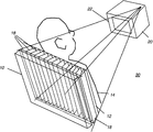
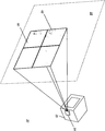
도 1의 사시도는 계산된 방사선 촬영(computed radiography: CR) 및/또는 디지털 방사선 촬영(digital radiography: DR)에 사용될 수 있는 기존의 이동식 x-선 장치의 일례를 도시한다. 이동식 방사선 촬영 유닛(600)은 획득된 이미지와 관련된 데이터를 디스플레이하기 위한 디스플레이(610)와, 획득된 이미지를 저장하고 전송하고 수정하고 인쇄하는 것과 같은 기능을 수행하는 제어 패널(612)을 포함하는 프레임(620)을 구비한다.The perspective view of FIG. 1 shows an example of a conventional mobile x-ray device that can be used for computed radiography (CR) and / or digital radiography (DR). The
이동을 위해, 유닛(600)은 하나 이상의 휠(615)과, 유닛(600)을 의도된 위치로 가이드하는 것을 도와주는, 일반적으로 허리 레벨, 팔 레벨 또는 손 레벨에 제공된 하나 이상의 핸들 그립(625)을 구비한다. 자체 포함된 배터리 팩이 일반적으로 소스 전력을 제공하여, 전력 콘센트 근처에서 동작해야 할 필요성을 제거한다.For movement, the
프레임(620)에는 지지 부재(635)가 장착되고, 이 지지 부재는, 보다 간단히 붐(boom)(70)이라고 지칭되는 붐 장치(70)에 장착되는, x-선 튜브 또는 튜브 헤드라고도 언급되는 x-선 소스(640)를 지지한다. 또한 튜브 헤드에 인접하게 또는 대안적으로 프레임(620) 내에 생성기가 장착될 수 있다. 도시된 실시예에서, 지지 부재(635)는 고정된 높이의 수직 컬럼(column)(64)을 구비한다. 붐(70)은 지지 부재(635)로부터 가변 거리로 외부쪽으로 연장하며 이미지를 획득하기 위해 컬럼(64)을 원하는 높이로 위 아래로 승강시킨다. 붐(70)은 고정된 거리만큼 외부쪽으로 연장하거나 가변 거리만큼 연장할 수 있다. x-선 소스(640)를 위한 높이 설정은 발과 하체를 이미징하기 위한 낮은 높이로부터 여러 위치에서 환자의 상체 부분을 이미징하기 위한 어께 높이와 그 이상에까지 이를 수 있다. 다른 종래의 실시예에서, x-선 소스를 위한 지지 부재는 고정된 컬럼이 아니라 관절식 부재이며, 이 관절식 부재는 수직 및 수평 위치의 범위에 걸쳐 x-선 소스를 이동시킬 수 있도록 하기 위해 조인트 메커니즘(joint mechanism)에서 벤딩된다.The
중환자실(ICU) 환경에서 사용되는 것과 같은 휴대용 방사선 이미징 장치의 출현으로, 시스템 그 자체의 장착 하드웨어에 의해 방사선 소스와 2차원 방사선 수신기 및 임의의 수반되는 그리드 사이에 더 이상 고정된 각도 관계가 부과되지 않는다. 대신, 오퍼레이터는 일반적으로 시각적 평가를 사용하여 가능한 한 배향을 수직으로 제공하는, 수신기 표면 쪽으로 방사선 소스를 겨냥할 것이 요구된다. 계산된 방사선 촬영(CR) 시스템에서 2차원 이미지 감지 장치 그 자체는 판독가능한 이미징 매체를 저장하는 휴대용 카세트(portable cassette)이다. 직접 디지털 방사선 촬영(DR) 시스템에서, 2차원 이미지 감지 수신기는 평평하고 강성이거나 유연한 기판 지지부를 가지는 디지털 검출기이다.With the advent of portable radiation imaging devices such as those used in intensive care unit (ICU) environments, there is no longer a fixed angle relationship between the radiation source and the two-dimensional radiation receiver and any accompanying grid by the mounting hardware of the system itself. It doesn't work. Instead, the operator is generally required to aim the radiation source towards the receiver surface, which provides the orientation as vertically as possible using visual assessment. In a computed radiography (CR) system the two-dimensional image sensing device itself is a portable cassette which stores a readable imaging medium. In a direct digital radiography (DR) system, the two-dimensional image sensing receiver is a digital detector with a flat, rigid or flexible substrate support.
그러나, 수신기 그 자체는 일단 이것이 환자 뒤에 배치된 경우 기술자에게 보이지 않을 수 있다. 이것은 SID, 틸트 각도 및 센터링을 측정하기 위한 몇몇 방법을 요구하고, 산란 효과를 줄이기 위해 그리드를 효과적으로 사용하는 것을 더 곤란하게 하는 휴대용 시스템을 위한 정렬 작업을 복잡하게 한다. 휴대용 방사선 촬영 시스템에 따른 이러한 추가적인 복잡성 때문에, 기술자는 그리드를 사용하지 말 것을 선택할 수 있는데, 그러나, 그리드가 없는 결과는 일반적으로 낮은 품질의 이미지이다.However, the receiver itself may not be visible to the technician once it is placed behind the patient. This requires some methods for measuring SID, tilt angle and centering and complicates the alignment task for portable systems, which makes it more difficult to use the grid effectively to reduce scattering effects. Because of this additional complexity with portable radiography systems, the technician may choose not to use the grid, but the result without the grid is generally a low quality image.
x-선 소스 대 수신기 각도의 오퍼레이터 조정을 지원하기 위해 방법과 도구를 제공하는 문제에 대해 다수의 접근법이 있었다. 하나의 종래의 접근법은 MacMahon에 특허 허여된 발명의 명칭이 "이동식 방사선 촬영 정렬 장치(Mobile Radiography Alignment Device)"인 미국 특허 제4,752,948호에 설명된 것과 같은 보다 컴팩트한 방식으로 기계적 정렬을 제공하는 것이었다. 플랫폼은 이미징 카세트와 방사선 소스 사이에 정렬을 유지하기 위해 선회가능한 표준을 구비한다. 그러나, 이런 유형의 복잡한 기계적인 해법은 x-선 시스템의 전반적인 유연성과 휴대성을 감소시키는 경향이 있다. Kwasnick 등에 특허 허여된 발명의 명칭이 "디지털 X-선 이미저 정렬 방법(Digital X-ray Imager Alignment Method)"인 미국 특허 제6,422,750호에서 제안된 것과 같은 다른 유형의 접근법은 정렬 그리드를 검출하기 위해 초기 낮은 노출 펄스를 사용하지만, 이 방법은 수신기가 환자 뒤에 장착된 후에는 수신기가 정렬되어야 하는 휴대용 이미징 조건에 적합하지 않을 수 있다.There have been a number of approaches to the problem of providing methods and tools to support operator coordination of x-ray source to receiver angles. One conventional approach has been to provide mechanical alignment in a more compact manner, such as described in US Pat. No. 4,752,948, entitled "Mobile Radiography Alignment Device," entitled MacMahon. . The platform has a pivotable standard to maintain alignment between the imaging cassette and the radiation source. However, complex mechanical solutions of this type tend to reduce the overall flexibility and portability of x-ray systems. Another type of approach, such as the one proposed in US Pat. No. 6,422,750, entitled "Digital X-ray Imager Alignment Method," titled Kwasnick et al., Is directed to detecting alignment grids. Although using an initial low exposure pulse, this method may not be suitable for portable imaging conditions where the receiver must be aligned after the receiver is mounted behind the patient.
다른 접근법은 방사선 소스와 수신기 사이에 정렬을 달성하기 위해 방사선 소스로부터 수신기로 광 빔을 투사한다. 이 접근법의 예로는 MacMahon에 특허 허여된 발명의 명칭이 "방사선 촬영을 위한 정렬 방법 및 이를 포함하는 방사선 촬영 장치(Alignment Method for Radiography and Radiography Apparatus Incorporating Same)"인 미국 특허 제5,388,143호 및 MacMahon에 특허 허여된 발명의 명칭이 "휴대용 방사선 촬영을 위한 광학적 그리드 정렬 시스템 및 이를 포함하는 휴대용 방사선 촬영 장치(Optical Grid Alignment System for Portable Radiography and Portable Radiography Apparatus Incorporating Same)"인 미국 특허 제5,241,578호가 포함된다. 유사하게, Cumings에 특허 허여된 발명의 명칭이 "방사선 빔을 방사하는 디바이스를 겨냥하는 방법, 시스템 및 장치(Method, System and Apparatus for Aiming a Device Emitting Radiant Beam)"인 미국 특허 제6,154,522호는 방사선 타깃을 정렬하기 위해 반사된 레이저 빔의 사용을 설명한다. 그러나, 광을 사용하여 필름 또는 CR 카세트 또는 DR 수신기를 정렬하도록 제공된 해법은 다수의 요인에 의해 제약된다. MacMahon에 특허 허여된 '143과 '578 문헌의 내용은 고정된 소스-이미지간 거리(SID)가 미리 결정되어야 하고, 이후에 이 고정된 SID 값을 가지고 삼각 측량을 적용해야 할 것을 요구한다. SID를 변경하면 삼각 측정 설정에 다수의 조정을 요구한다. 이러한 배열은 가변 SID를 허용하는 휴대용 이미징 시스템에 대해서는 바람직하지 않은 것이다. Cumings에 특허 허여된 '522 문헌의 내용에 설명된 바와 같은 레이저를 사용하는 장치는 일부 경우에 필요한 것보다 조정을 하는데 훨씬 더 높은 정밀도를 요구할 수 있다.Another approach projects a light beam from the radiation source to the receiver to achieve alignment between the radiation source and the receiver. Examples of this approach are described in US Pat. No. 5,388,143 and MacMahon, entitled "Alignment Method for Radiography and Radiography Apparatus Incorporating Same," entitled MacMahon. US Pat. No. 5,241,578, entitled "Optical Grid Alignment System for Portable Radiography and Portable Radiography Apparatus Incorporating Same," entitled "Optical Grid Alignment System for Portable Radiography." Similarly, U. S. Patent No. 6,154, 522, entitled Cumings, entitled "Method, System and Apparatus for Aiming a Device Emitting Radiant Beam," discloses radiation. The use of the reflected laser beam to align the target is described. However, the solution provided to align the film or CR cassette or DR receiver using light is limited by a number of factors. The contents of the '143 and' 578 patents issued to MacMahon require that a fixed source-image distance (SID) must be determined in advance, and then triangulation applied with this fixed SID value. Changing the SID requires a number of adjustments to the triangulation setup. This arrangement is undesirable for portable imaging systems that allow for variable SIDs. Devices using lasers, as described in Cumings patented '522, may require much higher precision to make adjustments than necessary in some cases.
광이 방사선 소스로부터 수신기로 투사되는 다른 예는 Bautista에 특허 허여된 발명의 명칭이 "탐지 장치(Locating Device)"인 미국 특허 제4,836,671호와, Madsen에 특허 허여된 "X-선 사진 장치(X-ray Photography Device)"인 미국 특허 제4,246,486호에 제공된다. Bautista에 특허 허여된 '671 문헌과 Madsen에 특허 허여된 '486 문헌의 접근법은 방사선 소스로부터 투사되고 여러 방식으로 수신기에서 교차되는 다수의 광원을 사용한다.Other examples in which light is projected from a radiation source to a receiver are described in US Pat. No. 4,836,671, entitled "Locating Device," as patented by Bautista, and "X-ray imaging device (X), patented by Madsen. -ray Photography Device, "US Patent No. 4,246,486. The approach of the '671 document, patented to Bautista and the' 486, patented to Madsen, uses multiple light sources that are projected from the radiation source and crossed in the receiver in many ways.
중요한 것은 위에서 언급된 해법은 예를 들어 휴대용 시스템으로 흉부를 x-선 이미징을 하기 위해 경우에 따라 수신기와 그 수반하는 그리드가 환자 뒤에 완전히 놓여서 시야에서 보이지 않는 것으로 인해 종종 가치가 거의 없거나 전혀 가치가 없다는 것이다. 오늘날의 휴대용 방사선 이미징 장치는 방사선 기술자에 의해 필름 카세트, CR 카세트, 또는 디지털 방사선 촬영 DR 수신기를 배치하기 위해 상당한 유연성을 허용한다. 환자는 이미징을 위해 수평 위치에 있을 필요가 없으며, 필요한 이미지의 유형 및 x-선 검사를 위해 환자를 이동할 수 있는 능력에 따라 임의의 각도에 있을 수 있다. 기술자는 각 이미징 세션에 독립적으로 카세트 또는 수신기 및 방사선 소스의 위치를 수동으로 조정할 수 있다. 따라서, 이 방사선 소스와 그리드 및 이미지 수신기 사이에 원하는 각도를 획득하기 위한 정렬 장치는 이미지를 획득하는데 가장 적합한 배향으로 적응할 수 있어야 한다는 것이 이해될 수 있을 것이다. 종래에 적용된 바와 같은, 그리고 Tanaka 등에 특허 허여된 발명의 명칭이 "휴대용 방사선 이미징 시스템 및 각도 신호 출력 수단을 구비하는 방사선 이미지 감지 장치(Portable Radiation Imaging System and a Radiation Image Detection Device Equipped with an Angular Signal Output Means)"인 미국 특허 제7,156,553호에 기술된 디바이스에 사용된 바와 같이, 그리고 그 외에 다른 곳에 사용된 바와 같은 틸트 감지는 카세트가 동일한 레벨에 놓여있는 단일한 경우를 제외하고 카세트-방사선 소스간 배향에 대해 충분한 정보를 제공하지 않는다. 더 복잡한 위치 감지 장치가 사용될 수 있지만, 샘플링을 받아 라운딩 에러들이 누적될 수 있어 이것이 시간에 따라 점점 더 악화되어 빈번한 재동기화를 요구할 수 있다.Importantly, the above-mentioned solutions are often of little or no value because, for example, the x-ray imaging of the chest with a portable system often results in the receiver and its accompanying grid being completely behind the patient and invisible in sight. It is not. Today's portable radiation imaging devices allow considerable flexibility for placing film cassettes, CR cassettes, or digital radiography DR receivers by a radiographer. The patient does not need to be in a horizontal position for imaging and may be at any angle depending on the type of image needed and the ability to move the patient for x-ray examination. The technician can manually adjust the position of the cassette or receiver and the radiation source independently for each imaging session. Thus, it will be appreciated that the alignment device for obtaining the desired angle between this radiation source and the grid and the image receiver should be able to adapt to the orientation most suitable for obtaining the image. The invention, as previously applied and patented by Tanaka et al., Is entitled "Portable Radiation Imaging System and a Radiation Image Detection Device Equipped with an Angular Signal Output." Tilt sensing, as used in the device described in US Pat. No. 7,156,553, and elsewhere, is a cassette-radial source orientation except for a single case where the cassette lies at the same level. Does not provide enough information about. More complex position sensing devices can be used, but rounding errors can be sampled and accumulate, which can get worse over time and require frequent resynchronization.
따라서, 기존의 정렬 해법은 특정 유형의 시스템과 환경에서 동작가능할 수 있으나, 상당한 개선의 여지가 남아 있다는 것이 명백하다. 휴대용 방사선 촬영 장치는 콤팩트하고 경량이어야 하여서 이는 바람직하지 않는 MacMahon에 특허 허여된 '948 문헌에 주어진 것과 같은 기계적 정렬 방식을 만들게 한다. 직접 시야 정렬에 대한 제약은 많은 유형의 반사된 광에 기초한 방법의 적용가능성을 이미징 상황의 제한된 범위로 감소시킨다. 다나카 등에 특허 허여된 '553 문헌의 해법에 의해 요구되는 복잡한 센서와 움직임 제어 상호작용은 제한된 이익으로 기존의 디자인에 상당한 비용, 복잡성, 중량 및 사이즈를 추가한다. 많은 적은 비용으로 휴대용 방사선 이미징 유닛은 필요한 조정을 달성하기 위해 필요한 제어 로직 및 움직임 조정 구성 요소를 가지지 않는다. 이들 접근법 중 어느 것도 특히 그리드가 사용되는 경우 오정렬을 정정하기 위해 올바름 방향으로 수동 조정을 하는데 필요한 정보를 오퍼레이터에게 제공하지 않는다.Thus, while existing alignment solutions may be operable in certain types of systems and environments, it is clear that significant room for improvement remains. The portable radiography device must be compact and lightweight, which leads to an undesirable mechanical alignment scheme as given in the '948 document patented by MacMahon, which is undesirable. Constraints on direct viewing alignment reduce the applicability of the method based on many types of reflected light to a limited range of imaging situations. The complex sensor and motion control interactions required by Tanaka et al.'S solution of the '553 document add significant cost, complexity, weight and size to existing designs with limited benefits. At much lower cost, portable radiation imaging units do not have the necessary control logic and motion adjustment components to achieve the necessary adjustments. None of these approaches provide the operator with the information needed to make manual adjustments in the right direction to correct misalignments, especially when grids are used.
위의 해법 중 많은 것에 의해 해결되지 않은 또 다른 문제는 방사선 의사 및 방사선 기술자의 실제 작업 관행에 관한 것이다. 다나카 등에 특허 허여된 '553 출원에서 특허 강조된 방사선의 수직 전달을 위한 요구사항이 모든 유형의 이미지에 적합하지 않기 때문에 모든 경우에 사용되지 않는다. 사실, 그리드 정렬이 주어진 각도에 허용가능한 한, 경사져(비수직으로) 입사하는 방사선 각도가 가장 바람직할 수 있는 진단 이미지의 일부 유형이 있다. 예를 들어, 표준 흉부 앞-뒤(AP) 뷰(anterior-posterior view)에 대해, 권고된 중심 방사선 각도는 약 3-5도만큼 수직선(법선)으로부터 경사져 있다. 기존의 정렬 시스템은, 중심 방사선이 법선(normal)으로 입사하는 것을 제공하지만 기술자가 경사진 각도로 조정하도록 지원하는 것을 채용하지는 않는다.Another problem that has not been solved by many of the above solutions relates to the actual working practices of radiologists and radiologists. The requirement for the vertical transmission of radiation, patented in Tanaka et al. '553 application, is not used in all cases because it is not suitable for all types of images. Indeed, there are some types of diagnostic images in which the angle of incidence (non-vertically) incident on which the grid alignment is acceptable for a given angle may be most desirable. For example, for a standard anterior-posterior view, the recommended central radiation angle is inclined from the vertical line (normal) by about 3-5 degrees. Existing alignment systems provide that the central radiation is incident at normal but does not employ to assist the technician in adjusting to the inclined angle.
더 다른 문제는 획득될 이미지와 사용되는 그리드에 매우 적합한 소스-이미지간 거리(SID)를 달성할 필요성에 관한 것이다. 종래의 정렬 해법은 SID 정보를 제공하지는 않아 기술자에게 별도의 측정을 하게 하거나 대략적인 SID 조정을 하게 한다. 또한, 기존의 해법은 콜리메이터 블레이드(collimator blade)의 오정렬 또는 불량한 조정으로 야기되는 후방 산란을 줄이는 것을 지원하는 도구를 기술자에게 제공하지 않는다. 이런 유형의 산란은 치과 및 유방 x-선 조영(mammographic) 이미징과 같은 방사선 투과 이미징의 다른 유형에는 특히 문제시 되지는 않으나, 방사선은 넓은 지역에 걸쳐 지향되기 때문에 휴대용 방사선 투과 이미징 장치에는 문제시 될 수 있다. 이미징 수신기를 지나 작동하는 방사선과 수신기와 연관된 임의의 차단 요소는 실수로 수신기로 다시 반사될 수 있고 이에 이미지 품질에 부정적으로 영향을 미칠 수 있다. 흉부 x-선 및 다른 유형의 x-선에 대해 가능한 한 많이 후방 산란을 감소시키기 위해, 기술자는 이미징 수신기의 위치와 배향 또는 윤곽을 추정하고 그에 따라 콜리메이터를 조정할 것이 요구된다.A further problem relates to the need to achieve a source-image distance (SID) which is very suitable for the image to be obtained and the grid used. Conventional alignment solutions do not provide SID information and allow a technician to make separate measurements or make rough SID adjustments. In addition, existing solutions do not provide the technician with tools to assist in reducing backscattering caused by misalignment or poor adjustment of the collimator blade. This type of scattering is not particularly problematic for other types of radiographic imaging, such as dental and mammographic imaging, but it is problematic for portable radiographic imaging devices because radiation is directed over large areas. Can be. Radiation operating past the imaging receiver and any blocking elements associated with the receiver can be accidentally reflected back to the receiver and negatively affect image quality. In order to reduce backscatter as much as possible for chest x-rays and other types of x-rays, the technician is required to estimate the position and orientation or contour of the imaging receiver and adjust the collimator accordingly.
따라서, 방사선 이미지를 기록하기 위해 이미지 수신기에 대해 방사선 소스의 적절한 각도 정렬 및 센터링을 가능하게 하는 장치에 대한 필요성이 존재한다는 것을 볼 수 있다.
Accordingly, it can be seen that there is a need for an apparatus that enables proper angular alignment and centering of a radiation source with respect to an image receiver for recording a radiographic image.
본 발명의 목적은 방사선 수신기에 대해 방사선 소스의 정렬과 적절한 위치지정을 지원하는 장치 및 방법을 제공하여 방사선 투과 이미징 기술을 개선하는 것이다. 본 발명의 관련된 목적은 소스-이미지간 거리와 소스에 대한 수신기의 각도 배향뿐만 아니라 x-선 빔의 경로에 대한 방사선 수신기의 위치와 윤곽을 나타내는 디스플레이를 제공하는 것이다. 이 디스플레이는 디스플레이 모니터에 나타나거나 또는 환자에 직접 투사될 수 있다.It is an object of the present invention to provide an apparatus and method for supporting the alignment and proper positioning of a radiation source with respect to a radiation receiver to improve radiation transmission imaging techniques. A related object of the present invention is to provide a display showing the location and contour of the radiation receiver with respect to the path of the x-ray beam as well as the source-image distance and the angular orientation of the receiver relative to the source. This display may appear on a display monitor or may be projected directly onto the patient.
이들 목적은 단지 예시로써 제공된 것이며, 이들 목적은 본 발명의 하나 이상의 실시예의 예시일 뿐이다. 본 발명에 의해 고유하게 달성되는 다른 바람직한 목적과 이점은 이 기술 분야에 통상의 지식을 가진 자에게 일어날 수 있거나 자명한 것일 수 있다. 본 발명은 첨부된 특허청구범위에 의해 한정된다.
These objects are provided by way of example only, and these objects are merely illustrative of one or more embodiments of the invention. Other desirable objects and advantages inherently achieved by the present invention may occur or become apparent to those skilled in the art. The invention is defined by the appended claims.
본 발명의 일 양태에 따르면, 피사체의 방사선 투과 이미지를 획득하기 위한 방사선 촬영 시스템이 제공될 수 있으며, 여기서 본 시스템은 방사선 경로를 따라 방사선 에너지를 지향시키도록 활성화될 수 있는 방사선 소스와; 방사선 투과 이미지를 형성하기 위해 상기 방사선 에너지에 민감한 이미징 수신기; 적어도 상기 수신기에 대한 방사선 경로의 센터링, 상기 방사선 경로에 대한 상기 수신기의 각도, 및 상기 방사선 경로를 따른 소스-이미지간 거리를 나타내는 하나 이상의 출력 신호를 제공하도록 배치된 센서 장치; 및 상기 하나 이상의 출력 신호에 응답하여, 상기 수신기에 대해 상기 방사선 경로의 센터링을 나타내고 적어도 상기 소스-이미지간 거리와 상기 방사선 경로에 대한 상기 수신기의 각도를 나타내는 하나 이상의 값을 제공하는 디스플레이를 생성하는 디스플레이 장치를 포함한다.According to one aspect of the invention, a radiographic system can be provided for obtaining a radiographic image of a subject, wherein the system comprises a radiation source that can be activated to direct radiation energy along a radiation path; An imaging receiver sensitive to the radiation energy to form a radiation transmission image; A sensor device arranged to provide one or more output signals indicative of at least centering of the radiation path relative to the receiver, angle of the receiver relative to the radiation path, and source-image distance along the radiation path; And responsive to the one or more output signals, generating a display for the receiver that provides one or more values representing centering of the radiation path and providing at least the source-image distance and the angle of the receiver relative to the radiation path. And a display device.
본 발명의 일 양태에 따르면, 피사체의 방사선 투과 이미지를 획득하기 위한 방사선 촬영 시스템이 제공될 수 있으며, 본 시스템은, 방사선 경로를 따라 방사선 에너지를 지향시키도록 활성화될 수 있는 방사선 소스; 방사선 투과 이미지를 디지털 이미지로 형성하기 위해 상기 방사선 에너지에 민감한 이미징 수신기; 적어도 상기 이미징 수신기의 윤곽, 상기 수신기에 대한 상기 방사선 경로의 센터링, 상기 방사선 경로에 대한 상기 수신기의 각도, 및 상기 방사선 경로를 따른 소스-이미지간 거리를 나타내는 하나 이상의 출력 신호를 제공하도록 배치된 센서 장치; 및 상기 하나 이상의 출력 신호에 응답하여 상기 이미징 수신기의 윤곽과 상기 수신기에 대한 상기 방사선 경로의 센터링을 나타내고 적어도 상기 소스-이미지간 거리와 상기 방사선 경로에 대한 상기 수신기의 각도를 나타내는 하나 이상의 수치 값을 디스플레이하는 디스플레이를 생성하는 디스플레이 장치를 포함한다.According to one aspect of the present invention, a radiographic system for obtaining a radiographic image of a subject may be provided, the system comprising: a radiation source that may be activated to direct radiation energy along a radiation path; An imaging receiver sensitive to the radiation energy for forming a radiographic image into a digital image; A sensor arranged to provide one or more output signals indicative of at least the contour of the imaging receiver, the centering of the radiation path with respect to the receiver, the angle of the receiver with respect to the radiation path, and the source-image distance along the radiation path. Device; And in response to the one or more output signals one or more numerical values representing the contour of the imaging receiver and the centering of the radiation path with respect to the receiver and at least indicating the source-image distance and the angle of the receiver with respect to the radiation path. And a display device for generating a display for displaying.
본 발명의 일 양태에 따르면, 피사체의 방사선 투과 이미지를 획득하기 위한 방법이 제공될 수 있으며, 본 방법은 방사선 소스로부터 방사선 경로에 대한 이미징 수신기의 센터링, 상기 방사선 경로에 대한 상기 수신기의 각도, 및 상기 방사선 경로를 따른 소스-이미지간 거리를 나타내는 하나 이상의 신호를 획득하는 단계; 및 상기 하나 이상의 획득된 신호에 응답하여, 적어도 상기 이미징 수신기의 센터링을 나타내고 상기 소스-이미지간 거리 또는 각도 또는 이들 둘 모두를 나타내는 하나 이상의 값을 디스플레이하는 디스플레이를 생성하는 단계를 포함한다.
According to one aspect of the invention, a method may be provided for obtaining a radiographic image of a subject, the method comprising centering an imaging receiver relative to a radiation path from a radiation source, angle of the receiver relative to the radiation path, and Acquiring one or more signals indicative of the source-image distance along the radiation path; And in response to the one or more acquired signals, generating a display that indicates at least one centering of the imaging receiver and displays one or more values indicative of the source-image distance or angle or both.
첨부된 도면에 도시된 바와 같이 본 발명의 상기 및 다른 목적, 특징 및 이점은 본 발명의 실시예들의 이하 보다 상세한 설명으로부터 명백할 것이다. 도면에 있는 요소들은 서로에 대하여 반드시 축척에 맞게 그려진 것은 아니다.
도 1은 기존의 이동식 방사선 촬영 유닛의 하나의 유형의 사시도;
도 2a는 진단 이미징 장치의 기본 구성 요소로 이미징되는 환자의 상대적 관계를 도시한 사시도;
도 2b는 이미징 시스템 설정을 위한 중요한 차원의 관계를 도시한 사시도;
도 2c는 예시적인 오정렬 위치를 도시한 사시도;
도 3a는 하나의 실시예에서 정렬 장치의 일부분의 작동을 도시한 사시도;
도 3b는 본 발명의 실시예에 따라 수신기/그리드 정렬에 적합한 튜브를 달성하는데 사용되는 구성 요소를 도시한 측면 블록도;
도 4는 환자 뒤에 또는 아래에 있는 수신기의 상대적 위치를 표시하는 데 사용되는 투사 이미지의 사시도;
도 5a는 이미징 수신기와 오정렬된 방사선 소스로부터 디스플레이된 콜리메이터 패턴을 도시한 사시도;
도 5b는 방사선 소스가 이미징 수신기와 오정렬된 수신기 패턴의 디스플레이를 도시한 사시도;
도 5c는 방사선 소스가 이미징 수신기와 오정렬된 프로젝터와 콜리메이터 광으로부터 투사되는 중복 패턴을 도시한 사시도;
도 5d는 이미징 수신기에 대한 방사선 소스의 정렬 및 투사되는 패턴의 대응하는 정렬을 도시한 사시도;
도 6은 프로젝터로부터 디스플레이를 위해 최대로 이용가능한 영역에 대해 수신기 패턴의 디스플레이를 도시한 사시도;
도 7a 및 도 7b는 센터링, 각도 및 거리 차이를 포함하는 여러 조건 하에서 투사되는 광 패턴이 정렬되는 방식을 도시한 도면;
도 8은 방사선 소스와 수신기 사이에 공간적 관계를 나타내는 정보를 디스플레이하기 위해 콜리메이터에 결합된 디스플레이 스크린의 사용을 도시한 평면도;
도 9a, 도 9b 및 도 9c는 디스플레이 장치로서 디스플레이 스크린을 사용하기 위한 오퍼레이터 인터페이스 예를 도시한 도면;
도 10은 대안적인 실시예에서 디스플레이 스크린을 위한 오퍼레이터 인터페이스 배열을 도시한 도면;
도 11은 방사선 소스 각도가 변할 때 배향을 변경시키는 콜리메이터의 근처에 장착된 디스플레이 스크린을 위한 오퍼레이터 인터페이스 디스플레이 스크린의 시퀀스를 도시한 도면;
도 12a는 본 발명의 일 실시예에 따라 콜리메이터에 프로젝터의 결합을 도시한 개략도;
도 12b는 콜리메이터에 프로젝터를 결합하기 위한 다른 방법을 도시한 개략도;
도 12c는 콜리메이터에 프로젝터를 결합하기 위한 다른 대안적인 방법을 도시한 개략도.The above and other objects, features and advantages of the present invention will be apparent from the following more detailed description of the embodiments of the present invention as shown in the accompanying drawings. Elements in the figures are not necessarily drawn to scale with respect to each other.
1 is a perspective view of one type of a conventional mobile radiography unit;
2A is a perspective view showing the relative relationship of a patient imaged with the basic components of the diagnostic imaging device;
2B is a perspective view showing important dimensional relationships for imaging system setup;
2C is a perspective view illustrating an exemplary misalignment position;
3A is a perspective view illustrating operation of a portion of the alignment device in one embodiment;
3B is a side block diagram illustrating components used to achieve a tube suitable for receiver / grid alignment in accordance with an embodiment of the present invention;
4 is a perspective view of a projection image used to indicate the relative position of a receiver behind or below a patient;
5A is a perspective view showing a collimator pattern displayed from an imaging receiver and a misaligned radiation source;
5B is a perspective view illustrating display of a receiver pattern in which a radiation source is misaligned with the imaging receiver;
5C is a perspective view showing the overlapping pattern in which the radiation source is projected from the imaging receiver and the misaligned projector and collimator light;
5D is a perspective view showing the alignment of the radiation source with respect to the imaging receiver and the corresponding alignment of the projected pattern;
6 is a perspective view showing the display of the receiver pattern for the maximum available area for display from the projector;
7a and 7b show how the light patterns projected under various conditions including centering, angle and distance difference are aligned;
8 is a plan view illustrating the use of a display screen coupled to a collimator to display information indicative of a spatial relationship between a radiation source and a receiver;
9A, 9B and 9C illustrate an example of an operator interface for using a display screen as a display device;
10 illustrates an operator interface arrangement for a display screen in an alternative embodiment;
FIG. 11 shows a sequence of operator interface display screens for display screens mounted near the collimator that change orientation when the radiation source angle changes.
12A is a schematic diagram illustrating coupling of a projector to a collimator in accordance with one embodiment of the present invention;
12B is a schematic diagram illustrating another method for coupling a projector to a collimator;
12C is a schematic diagram illustrating another alternative method for coupling a projector to a collimator.
이하는 도면이 참조되는 본 발명의 바람직한 실시예에 대한 상세한 설명이며 여기서 동일한 도면 부호는 여러 도면 각각에서 동일한 구조 요소를 나타낸다.The following is a detailed description of a preferred embodiment of the present invention with reference to the drawings, wherein like reference numerals designate like structural elements in each of the various figures.
본 발명의 문맥에서, '이미징 수신기(imaging receiver)" 또는 더 간단하게 "수신기"는 예를 들어 필름이나 형광 매체와 같은 광자극가능한(photostimulable) 매체를 가지는 카세트를 포함할 수 있으며 또는 방사선 소스로부터 방출되는 방사선에 따라 이미지를 기록하는 검출기 어레이를 포함할 수 있다.In the context of the present invention, an 'imaging receiver' or more simply a "receiver" may comprise a cassette having a photostimulable medium such as, for example, a film or fluorescent medium or from a radiation source. It may include a detector array for recording an image in accordance with the radiation emitted.
본 명세서에 사용된 바와 같이 '활성화될 수 있는(energizable)"이라는 용어는 전력을 수신할 때 그리고 선택적으로 작동 신호를 수신할 때 지시된 기능을 수행하는 구성 요소의 장치 또는 세트를 나타낸다.As used herein, the term 'energizable' refers to an apparatus or set of components that performs the indicated functions when receiving power and optionally when receiving an actuation signal.
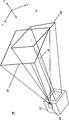
도 2a의 사시도는 방사선 투과 이미징 장치(30)의 구성 요소를 도시한다. x-선 소스와 같은 방사선 소스(20)는 환자(14) 쪽으로 방사선을 지향시킨다. 환자 뒤에 위치된 수신기(10)는 환자(14)를 통과하여 입사하는 방사선으로부터 진단 이미지를 형성한다. 수신기(10)는 예를 들어, 필름이나 형광 매체와 같은 광자극가능한 매체를 구비할 수 있으며 또는 방사선 소스(20)로부터 방출된 방사선에 따라 이미지를 기록하는 검출기 어레이를 구비할 수 있다. 수신기(10)는 가로 또는 세로 배향(landscape or portrait orientation)을 구비할 수 있다. 선택적인 산란 방지(antiscatter) 그리드(12)는 수신기(10)의 표면 바로 위에 도 1a에 도시된 바와 같이 배열된 판(18)을 구비한다. 방사선 소스(20)는 도 2a의 예에서 수신기(10) 쪽으로 소스(20)로부터 외부 쪽으로 지향되는 방사선 영역을 한정하는 콜리메이터(22)를 구비한다.The perspective view of FIG. 2A shows the components of the radiation transmitting
방사선 소스(20)는 수신기(10) 쪽으로 방사선을 지향시키기 위해 조절가능한 각도 배향을 구비한다. 도 2b{여기서 환자(14)는 시스템 구성 요소를 더 잘 볼 수 있도록 하기 위해 미도시되었음}는 좌표 xyz 축을 도시한다. 여기서, 소스-이미지간 거리(SID)는 z축의 일반적인 방향에 있다. 도 2b에서 방사선 소스(20)는 수신기(10)로부터 적절한 SID에서 정렬된 위치에 있다. 각각의 면이 SID에 수렴되는 초점 라인(L)을 정의하도록 그리드 판(18)이 각지게 배열된다. 이러한 실시예에서 최상의 이미징을 위한 최상의 정렬을 위해, 방사선 소스(20)는 초점 라인(L) 근처에 센터링되어야 하고 수신기(10)의 평면인 표면과 일반적으로 평행하게 콜리메이터(22)의 면부분을 가져야 한다. 그러나, 약간의 각도 오프셋이 선호되는 이미지 유형이 있을 수 있다.The
도 2c는 이와 대조적으로, 방사선 소스(20)의 위치지정이 불량한 20'과 20"에서 점선 윤곽을 도시한다. 점선으로 도시된 위치(20', 20")에서 SID는 거의 허용될 수 있지만, 방사선 소스(20)는 초점 라인(L) 근처에 센터링하지 않고 그 각도 배향은 불량하게 뒤틀려(skewed) 있다. 그리드와 방사선 소스를 정렬하는 것은 이들 및 유사한 오정렬 위치에서 불량할 수 있으며 이에 이미지 품질을 저하시키거나 최악으로는 적절한 진단 이미지를 획득할 수 없게 한다.FIG. 2C, in contrast, shows dashed outlines at 20 'and 20 "with poor positioning of the
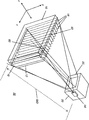
도 3a의 사시도 및 도 3b의 측면도는 중심 축에 대해 분산되고 경로 R로 표시된 방사선 경로를 가지는 방사선 소스(20)와, 방사선 투과 이미지를 형성하기 위해 피사체에 인접하여 위치된 방사선 에너지에 민감한 이미징 수신기(10) 사이에 상대적 공간적 관계를 감지하고 상대적인 공간적 관계를 나타내는 하나 이상의 출력 신호를 생성하도록 활성화될 수 있는 센서 장치(40)의 사용을 도시한다. 도 3a 및 3b에 도시된 실시예에서, 홀더(46)는 콜리메이터(22) 근처에 장착되게 도시된 하나 이상의 센서 요소(44)에 의해 검출된 전자기장 또는 신호를 생성하는 하나 이상의 전자기 코일(42)을 구비한다. 홀더(46)는 또한 수신기(10)를 지지한다. 다른 실시예에서, 센서 장치(40) 구성 요소는 수신기(10)에 형성된다. 또 다른 대안적인 실시예에서, 신호는 콜리메이터(22)에 하나 이상의 구성 요소로 생성되고 수신기(10) 상에 있는 센서 요소에 의해 검출된다. 각도 측정을 획득하기 위해 추가적인 경사계(inclinometer)(28) 또는 다른 장치가 수신기(10) 또는 방사선 소스(20) 중 어느 하나 또는 둘 모두에 제공될 수 있다.The perspective view of FIG. 3A and the side view of FIG. 3B show a
위치-감지 기술 분야에서 통상의 지식을 가진 자라면, 위치를 감지하고 각도 데이터, SID, 수신기(10) 윤곽을 추적하는 데이터 및 수신기(10)가 환자 뒤에 또는 아래에 위치된 센터링 정보를 제공하는 센서 장치(40)로서 사용될 수 있는 가능한 구성이 다수 있다는 것을 이해할 수 있을 것이다. 센터링은 방사선 경로에 대한 수신기(10)의 센터의 위치에 관한 것이거나, 또는 대안적으로 고려되는 것으로 수신기(10)의 센터에 대한 방사선 경로의 방향에 관한 것이다. 소스-물체간 거리(source-to-object distance; SOD), 여기서는 x-선 소스와 환자 사이의 거리가 또한 검출될 수 있다.One of ordinary skill in the art of position-sensing technology detects position and provides angle data, SID, data to track the contour of the
위치 감지 신호는 예를 들어, 아날로그 신호 또는 신호들 또는 하나 이상의 데이터 값일 수 있다. 신호는 예를 들어 경사계, 무선 주파수 장치, 전자기 코일, 및 오디오 신호를 포함하는 다수의 유형의 센서 및 센서-판독기 장치 중 어느 것으로부터 온 것일 수 있다. 센서는 그리드, 홀더 또는 수신기의 코너에 위치될 수 있거나, 또는 그리드, 홀더 또는 수신기 설계 그 자체에 통합될 수 있다. 사용되는 센서 구성이 무엇이든 간에, 센서 장치(40)로부터 하나 이상의 위치-감지 신호가 디스플레이 장치(50)를 위한 제어 로직을 제공하는 제어 논리 프로세서(48)로 간다.The position sensing signal may be, for example, an analog signal or signals or one or more data values. The signal may be from any of a number of types of sensors and sensor-reader devices, including, for example, inclinometers, radio frequency devices, electromagnetic coils, and audio signals. The sensor may be located at the corner of the grid, holder or receiver, or may be integrated into the grid, holder or receiver design itself. Whatever sensor configuration is used, one or more position-sensing signals from
디스플레이 장치(50)는 위치-감지 신호에 응답하여 방사선 경로(R)에 대해 수신기(10)의 배치를 기술자에게 보여주는 디스플레이를 생성하도록 활성화될 수 있다. 도 3b에 도시된 실시예에서 디스플레이 장치(50)는 정렬을 지원하도록 디스플레이된 이미지를 형성하는 디스플레이 스크린(52)과, 투사에 의하여 디스플레이를 형성하는 프로젝터(54)를 구비하며, 여기서 투사된 디스플레이는 수신기 위치 및 이와 관련된 정보를 나타내도록 이미지를 투사하는 것에 의해 조정을 지원하는 정보를 포함한다. 디스플레이 장치(50)는 프로젝터(54)와 디스플레이 스크린(52) 장치 중 어느 하나 또는 둘 모두를 장착할 수 있다. 일 실시예에서, 수치 SID와 각도 배향 값은 프로젝터(54)를 사용하여 디스플레이된 센터링 데이터를 가지게 디스플레이 스크린(52)에만 나타난다. 대안적으로, SID 및 각도 배향 값은 센터링 타깃과 함께 환자에 투사될 수 있다. 이 SID와 수신기에 입사하는 방사선의 양 사이에는 역 제곱 관계가 있기 때문에 실제 SID 값을 디스플레이하는 것은 흉부 이미징과 같은 방사선 투과 이미징에 특히 유용할 수 있다는 것을 주목해야 한다. 비교를 해보면, 기존의 방사선 장비의 설계에 의하여 그리고 이들 유형의 이미징에 사용되는 기존의 관행에 의하여 위치 및 허용 오차가 지시된 가까운 거리가 사용되므로 치과 및 유방 x-선 조영 이미지를 획득할 때 SID 값은 일반적으로 오퍼레이터에 우려할 문제는 아니다.
The
디스플레이 장치(50)로서 프로젝터(54)
도 3b 및 그 이후 도면에서 x-선 소스(20)에 장착된 것으로 도시된 프로젝터(54)는 예를 들어, 미국 워싱턴주의 레드몬드시에 소재하는 Microvision사로부터 Pico Projector Display 또는 캘리포니아주의 산타아나시에 소재하는 AAXA 테크놀로지사로부터 Micro Projector와 같은 피코-프로젝터(pico-projector)일 수 있다. 이들과 같은 이미지 형성 디바이스는 소형 사이즈, 작은 중량 및 저전력 요구 사항을 포함하는 다수의 이유 때문에 유리하다. 현재 휴대 전화 및 다른 고도의 휴대용 전자 기기에 사용되는 이들 작은 바닥면적 프로젝터(small-footprint projector)는 발광 다이오드(LED) 또는 레이저와 같은 하나 이상의 저전력 고체 광원을 디스플레이 표면 위에 스캔한다. 이러한 유형의 프로젝터는 일정 거리의 범위에 걸쳐 투사를 하기 위한 작은 개수의 광학 부품을 요구한다. 투사되는 이미지 픽셀에만 전력이 소비되도록 고체 광원 그 자체는 일반적으로 필요한 만큼 신속하게 턴온 및 턴오프될 수 있다. 이것은 디스플레이 장치가 낮은 전력 레벨에서 작동될 수 있게 하여, 배터리 전력이 프로젝터(54)를 위해 사용될 수 있게 한다. 대안적인 실시예는 텍사스 인스트루먼트사(Texas Instruments, Inc.)로부터 디지털 라이트 프로세서(Digital Light Processor: DLP)와 같은 디지털 마이크로 미러(micromirror) 어레이; 실리콘 라이트 머신사(Silicon Light Machines, Inc.)로부터 회절 격자 광밸브(Grating Light Valve: GLV) 장치와 같은 마이크로 전자기계 회절 격자 광밸브의 어레이; 또는 실리콘 위 액정(Liquid Crystal on Silicon: LCOS) 장치를 포함하는 액정 장치(LCD)를 사용하는 것과 같은 이미지 형성 장치로서 다른 유형의 전자 이미징 프로젝터를 사용한다. 다른 실시예에서, 프로젝터(54)는 타깃을 이동시키는 모터 또는 다른 액추에이터를 가지고 광원과 이동가능한 타깃에 의하여 제공되고, 여기서 타깃은 수신기 위치를 보여주는 이미지를 제공하기 위해 광원의 경로에 위치된다.The
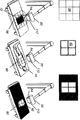
도 4의 사시도는 프로젝터(54)가 본 발명의 일 실시예에 따라 디스플레이 기능을 수행하는 방법을 도시한다. 프로젝터(54)는 좌측에 도시된 바와 같이, 수신기(10)의 영역을 초과하는 이미지 영역(58) 위에 이미지를 형성하도록 광을 투사할 수 있다. 수신기(10)가 센서 장치(40)를 사용하여 위치되는 경우, 프로젝터(54)는 환자(14)에 수신기 패턴(60)을 디스플레이하고, 상기 수신기 패턴(60)은 적어도 환자(14) 뒤에 또는 아래에 수신기(10)의 위치를 보여주는 윤곽을 나타낸다. 우측에는 원하는 정렬이 도시되며 여기서 x-선 튜브 헤드에 있는 콜리메이터 광원으로부터 방출된 콜리메이터 패턴(62)이 수신기 패턴(60)과 정렬된다. 특히, 이 배열로, 프로젝터(54)는 수신기(10)의 사이즈를 초과하는 영역에 걸쳐 이미지를 투사하여, 수신기(10) 위에 방사선 경로와 콜리메이터의 센터링에 앞서 수신기(10)의 윤곽이 디스플레이될 수 있게 한다.4 illustrates how the
도 5a의 사시도는 (이전에 설명된 바와 같은 축(R)을 따라 센터링된) 방사선 소스(20)의 방사선 경로가 수신기(10) 또는 그 그리드(12)와 정렬되지 않은 공간적 배열로 방사선 소스(20)로부터 디스플레이되는 콜리메이터 패턴(62)을 도시한다. 도 5b의 사시도는 수신기 패턴(60)을 수신기(10)에 직접 투사하는 디스플레이 장치(50)에 있는 프로젝터(54)를 도시한다. 도 5c는 방사선 소스(20)와 수신기(10) 사이에 불량한 정렬을 나타내는 중복된 경로와 불일치는 패턴(60 및 62)을 도시한다. 도 5d의 사시도는 올바른 정렬을 도시하며, 여기서 수신기 패턴(60)과 콜리메이터 패턴(62)은 센터 정렬되고 대칭적이다. 수신기(10)가 방사선 소스(20)에 대하여 너무 멀리 있거나 또는 너무 가까이 있어 SID가 부정확한 경우에는, 프로젝터(54)와 콜리메이터 패턴(62) 사이의 시차(parallax) 문제가 발생할 수 있다는 것이 관찰될 수 있다.The perspective view of FIG. 5A shows the radiation source (in a spatial arrangement in which the radiation path of the radiation source 20 (centered along axis R as described previously) is not aligned with the
프로젝터(54)의 초점은 여러 가지 방법으로 달성될 수 있다. 레이저 프로젝터는 초점 조정을 필요로 하지 않는다. 자동 초점 장치는 예를 들어 소스로부터 이미징되는 피사체까지의 거리를 측정하기 위해 초음파 신호 또는 적외선(IR) 광과 같은 거리 탐지 신호를 사용하는 다른 프로젝터 유형에서 사용될 수 있다. 도 4는 피사체와의 거리를 결정하기 위해 프로젝터(54)와 신호 통신하는 자동 초점 장치(112)를 도시한다. 자동 초점 및 거리 탐지 방법 및 장치는 저렴하고 이미지 캡처 기술 분야에 통상의 지식을 가진 사람들에게 잘 알려져 있다. 대안적으로, 센서 장치(40)로부터 정보는 초점 거리를 결정하는 데 사용되고 자동 초점을 위해 사용될 수 있다.The focus of the
도 6의 사시도는 투사된 패턴(60)의 사이즈를 초과하는 영역을 가지는 프로젝터 영역(58)을 도시한다. 이 기능은 프로젝터(54)가 소스-수신기 정렬에 필요한 정보를 디스플레이할 수 있게 한다.The perspective view of FIG. 6 shows a
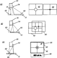
필요한 조정은 목표 센터링과 방사선 경로에 대한 수신기의 각도 및 방사선 경로에 대한 소스-이미지간 거리와 같은 파라미터에 대해 방사선 소스(20)와 수신기(10) 사이에 공간적 관계에 관한 것이다. 수신기 윤곽의 디스플레이는 또한 후방 산란을 감소시키는 콜리메이터 조정을 하기 위한 값이다.The necessary adjustment relates to the spatial relationship between the
프로젝터(54)로부터 그리고 x-선 튜브 헤드의 콜리메이터 광으로부터의 디스플레이된 패턴들의 위치 관계는 정렬 지시기로서 사용될 수 있다. 예를 들어, 도 7a는 프로젝터(54)로부터 수신기 패턴(60)과 콜리메이터 광으로부터의 콜리메이터 패턴(62)의 정렬이 수신기(10)와 방사선 소스(20)의 필요한 정렬 조정을 나타내는 방법을 도시한다. (60) 및 (62)에 표시된 패턴은 예시를 위하여 선택된 대표적인 예이며, 도 7a 및 도 7b의 예에 도시된 바와 같이 중심 원을 가지거나 가지지 않고 십자선 패턴을 포함하는 십자선 패턴을 포함하나 이로 국한되지 않는 다수의 형태 중 어느 것을 취할 수 있다. 상대적 위치(90)에서, 소스(20)와 수신기(10)는 정렬되어 있지 않고 각 패턴(62, 60)은 이 오정렬을 나타낸다. 상대적 위치(92)에서, 소스(20)는 수신기(10)와 정렬을 위해 더 가까이 있고, 위치(90)에 도시된 것보다 센터링에 더 가깝고, 패턴(62) 및 (60)은 다소 중복되지만 서로에 대하여 센터링되어 있지 않은 것을 디스플레이한다. 상대적인 위치(94)에서, 소스(20)와 수신기(10)는 정렬되어 있고 디스플레이된 각 패턴(62) 및 (60)은 이 센터링 정렬을 나타내도록 중복된다. 또한, 동일한 사이즈에서 실질적으로 동일한 영역에 걸쳐 두 패턴(60) 및 (62)을 가지는 위치(94)는 또한 방사선 분포를 제한하고 후방 산란의 가능성을 줄이도록 콜리메이터가 적절히 설정되었는지를 나타낸다. SID와 각도에 대한 값(66)은 또한 프로젝터(54)에 의해 디스플레이된다. 다른 실시예에서, 소스-피사체간 거리(SOD)가 또한 디스플레이된다. 투사된 값은 수신기 패턴(60) 내 또는 외부에 위치될 수 있다. 콜리메이터 블레이드의 위치를 감지할 수 있는 다른 실시예에서, 적절한 사이즈 조정 및 콜리메이트된 광 빔을 배향하는 것에 대한 추가적인 정보가 또한 디스플레이에 제공될 수 있다.The positional relationship of the displayed patterns from the
도 7b는 소스(20)와 수신기(10)의 불량한 상대적 위치를 나타내는 다른 예를 도시한다. 상대적 위치(96)에서, 소스(20)는 수신기(10)에 대하여 거의 센터링되어 있으나, 각도는 법선(normal)으로부터 뒤틀려(skewed) 있다. 수신기 패턴(60)은 이에 따라 예를 들어, 소스(20)와 수신기(10)부터 방사선 경로의 각도 관계를 나타내는 키스톤(keystone) 패턴을 갖는 것과 같은 비-직사각형이다. 상대적 위치(98)에서, 소스(20)는 수신기(10)에 대하여 거의 센터링되어 있으나, 소스-이미지간 거리(SID)가 부정확하고, 또는 만약 정확한 경우에는 콜리메이터는 후방 산란을 줄이기 위해 조정되어야 한다. 이 경우에, 각 패턴(60) 및 (62)은 SID 조정의 필요성을 나타내기 위해 서로 다른 크기의 것으로 나타난다.7B shows another example showing poor relative positions of the
프로젝션이 수신기(10) 윤곽에 더하여, 디스플레이 장치(50)에 사용되는 경우, 다음과 같은 다양한 유형의 정보가 예를 들어, 환자 옆에 또는 위에 디스플레이될 수 있다:When projection is used in the
a) 컬러 광을 가지는 수신기의 위치. 정렬을 지원하는 동일한 센서를 사용하여 장치는 이미징 수신기의 윤곽을 감지하여 강조 표시할 수 있다.a) location of the receiver with colored light. Using the same sensor that supports alignment, the device can detect and highlight the contour of the imaging receiver.
b) 환자에 대한 AEC 위치. 다른 디스플레이 표현이 활성 및 비활성 AEC 셀에 대해 사용된다. AEC 위치의 투사는 Michael C. Lalena 등에 의해 2011년 4월 11일 출원된 공동 양도되고 공동 계류 중인 미국 특허 출원 제13/083,776호에 설명된다.b) AEC location for the patient. Different display representations are used for active and inactive AEC cells. Projection of the AEC position is described in commonly assigned and co-pending US patent application Ser. No. 13 / 083,776, filed April 11, 2011 by Michael C. Lalena et al.
c) 그리드 비, 가로 대 세로 그리드 배향을 포함하는 그리드 정보.c) grid information including grid ratio, horizontal to vertical grid orientation.
d) 사용되는 시험 및 그리드의 유형이 주어진 경우 디폴트에 의해 또는 시스템 로직에 의해 제공된 실제 SID 및 권고 SID.d) the actual SID and the recommended SID provided by default or by system logic, given the type of test and grid used.
e) 이것이 올바른 환자인지 올바른 시험인지 확인하기 위하여 환자 시험 정보에 대한 정보: 환자 번호, 룸 번호, 환자 ID, DOB.e) Information about patient test information to determine whether this is the correct patient or the correct test: patient number, room number, patient ID, DOB.
f) 환자에 투사된, 후술되는 바와 같은 디스플레이 모니터에 디스플레이되는 정렬 정보의 부분 집합.
f) a subset of the alignment information displayed on the display monitor as described below, projected onto the patient.
디스플레이 장치(50)로서 디스플레이 스크린(52)
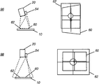
도 8은 디스플레이 장치(50)의 다른 실시예에서 프로젝터(54)를 보완하거나 대신할 수 있는 디스플레이 스크린(52)을 도시한다. 하나의 실시예에서, 디스플레이 스크린(52)은 방사선 소스(20)를 위치로 이동하는 동안 오퍼레이터가 디스플레이된 결과를 볼 수 있도록 도시된 바와 같이 콜리메이터(22) 근처에 장착된다. 다른 실시예에서, 정렬 설비가 제거가능한 또는 원격 디스플레이 스크린이나 디스플레이(610)(도 1), 방사선 투과 이미징 장치(30) 그 자체의 일부인 디스플레이 콘솔 위에 제공될 수 있다.8 shows a
도 9a, 도 9b 및 도 9c는 디스플레이 장치(50)로서 디스플레이 스크린(52)을 사용할 때 오퍼레이터의 인터페이스 예를 도시한다. 다양한 그래픽 아이콘과 이미지가 적절한 센터링, 각도 및 SID에 필요한 조정을 심볼화하기 위해 사용된다. 각도 조정 지시기(100)는 수신기(10)에 대해 소스(20)의 적절한 각도 조정을 가이드하는 것을 도와주기 위해 다양한 그래픽 및 측정 데이터를 제공한다. 각도 정보는 다음 사항 중 하나 이상을 디스플레이한다:9A, 9B and 9C show examples of the interface of the operator when using the
(i) 수신기 각도. 참된 수평선에 대한 각도 측정은 선택적인 경사계(28)(도 3b)로부터 또는 다른 센서 장치(40) 데이터로부터 획득할 수 있다.(i) Receiver angle. The angle measurement with respect to the true horizontal line can be obtained from the optional inclinometer 28 (FIG. 3B) or from
(ii) 방사선 소스(20)를 위한 튜브 각도. 참된 수평선에 대한 이 각도 측정은 경사계(28) 또는 다른 센서 장치(40) 데이터로부터 유사하게 계산될 수 있다.(ii) tube angle for the
(iii) 소스(20)와 수신기/그리드의 각도. 수신기(10)와 소스(20) 사이의 상대적인 각도 측정은 하나 이상의 선택적인 경사계(28)(도 3B) 또는 다른 센서 장치(40) 데이터로부터 측정값을 사용하여 획득될 수 있다.(iii) the angle of the
(iv) 소스-그리드(12) 정렬을 위한 교차 각도 데이터.(iv) intersection angle data for source-
(v) 센서 장치(40) 측정으로부터 계산된 원하는 각도에 대하여 소스-수신기 각도. 이것은 비 법선 각도에 대한 조정을 포함한다.(v) the source-receiver angle relative to the desired angle calculated from the
SID 지시기(110)는 측정된 데이터로부터 획득된 목록 현재 SID 값을 나열할 뿐 아니라, 도시된 실시예에서, 필요한 조정의 양을 표시한다. 센터링 지시기(120)는 센터링 에러와 필요한 조정 방향에 대한 텍스트와 그래픽 정보를 제공한다. 도 9b에서 센터링 지시기(120)는 수신기의 가로/세로 배향을 나타내는 그래픽 요소(104)를 포함한다. 아이콘(102)은 컬러, 플래시 또는 비디오 클립을 포함하는 애니메이션, 및 대응하는 값에 필요한 조정 방향을 나타내기 위한 상이한 유형의 심볼을 사용한다. 그래픽 요소(104)는 또한 시각적으로 필요한 조정을 나타내는 것을 지원하도록 제공된다. 그래픽 요소(104)는 원(circle), 바(bar), 또는 다른 형상을 포함하는 다수의 유형의 적절한 요소 중 어느 것일 수 있다. 컬러는 올바른 각도, 센터링, 또는 거리 값을 나타내는데 사용될 수 있으며, 컬러의 차이는, 필요한 경우 필요한 변화의 권고 방향을 나타내며, 컬러의 전환은 위치들 사이에 움직임을 나타낸다. 다양한 임계 값은 조정이 원하는 설정값에 얼마나 가까운지를 결정하는 데 사용된다.The
도 10은 디스플레이 스크린(52) 위 오퍼레이터 인터페이스에 대한 대안적인 실시예의 평면도를 도시한다. SID 지시기(110)는 측정된 데이터로부터 획득된 현재 SID 값을 나열한다. 여기서, 그래픽 요소(104)는 센터링, 거리 및 각도에 필요한 조정의 상대적인 양을 표시하는 슬라이더(slider)를 포함한다. 슬라이더의 센터링은 올바른 위치를 나타낸다. 각도 조정 지시기(100)는 수평에 대하여 또는 선택적으로 서로에 대하여 또는 원하는 설정에 대하여 수신기 또는 x-선 소스에 대한 측정된 각도 값을 표시한다. 선택적인 실시예에서, 상대 각도들 사이의 차이가 디스플레이된다. 센터링 지시기(120)는 x-선 빔의 상대적 위치와 형태를 표시하는 중복된 아이콘(122)과 함께 세로 또는 가로 배향에서와 같은 수신기(10)의 이미지 또는 윤곽을 표시한다. 제어 버튼(124)은 정렬을 개선하고 시스템 또는 시스템 구성 요소에 대한 정보, 및 기타 기능을 획득하는데 유용한 능력을 제공한다. 다른 실시예에서, 제어 버튼(124) 중 하나는 들어오는 방사선 투과 이미지(예를 들어, AP 흉부 검사 뷰 유형과 같은 것)에 대한 뷰 유형(view type)을 설정하고, 만약 있는 경우, 사용되는 그리드의 유형을 나타내는데 사용될 수 있다. 이 설정은 이미지에 대한 특정 SID와 각도 값이 할당되고 디스플레이될 수 있게 한다.10 shows a top view of an alternative embodiment for an operator interface on
도 11은 콜리메이터(22) 근처에 장착되고 방사선 소스(20) 각도가 변할 때 배향을 변경시키는 디스플레이 스크린(52)에 대한 오퍼레이터 인터페이스 디스플레이 스크린의 시퀀스를 도시한다. 위치(130)에서, 수신기 아이콘(132)은 센터링 타깃 아이콘(134)과 방사선 소스 아이콘(136)과 함께 디스플레이된다. 위치(140)에서, 센터링은 부분적으로 달성되지만, 방사선 소스(20)는 수신기 쪽으로 재지향되어야 한다. 위치(150)에서, 방사선 소스(20)는 튜닝되고 있고, 스크린은 수신기 아이콘(132) 및 아이콘(134), (136)으로 구성 요소의 위치를 나타내기 위해 자기 자신을 동적으로 재배향한다. SID 아이콘(152)은 수신기와 방사선 소스의 거리를 조정해야 하는 것을 그래픽으로 도시한다. SID 아이콘(152)은 SID가 변할 때 위치를 변경한다. 위치(160)에서, 적절한 센터링, 각도 및 SID가 획득된다. SID 값은 SID 지시기(110)에 도시된 대로 디스플레이된다.FIG. 11 shows a sequence of operator interface display screens for
본 발명의 실시예에서, 디스플레이 장치(50)는 x-선 소스와 수신기의 위치에 대한 상당한 정보뿐만 아니라 이미징 세션과 관련될 수 있는 다른 유형의 정보를 제공한다. 이것은 날짜, 시간, 온도 또는 다른 환경 조건, 식별 번호, 일련 번호, 또는 제조사 및 모델 식별자와 같은 방사선 촬영 장치 그 자체에 관한 정보를 포함할 수 있다. 일 실시예에서, 지침, 권고 또는 경고 정보가 또한 어떤 유형의 이미지가 정렬되었는지 그리고 제안된 설정 및 노출 값에 대한 정보를 포함하여 필요한 조정을 만들거나 이미지를 획득할 때 오퍼레이터를 보조하도록 제공된다. 검출기 정보가 또한 디스플레이될 수 있다. 이름, 연령, 생년월일, 환자 번호, 객실 번호, 측정 값 또는 환자의 혈액형에 대한 정보 등을 포함하는 환자 식별 데이터가 나열될 수 있다.In an embodiment of the present invention,
선택적인 디스플레이시 스크린(52)을 사용하는 실시예에서, 오퍼레이터에 의해 편집 또는 입력하기 위한 기능은 또한 kVp, mA, mAs, 시간, ECF, 초점 스폿, 콜리메이터 설정, AEC 설정, 권고되거나 사용되는 그리드 유형 및 검출기 유형을 포함하는 생성기 값과 같은 원하는 노출 설정 값의 입력 또는 편집을 포함하여 제공될 수 있다. 이 환자로부터 요청된 이미지와 뷰의 작업 리스트를 제공하는 작업리스트가 또한 일 실시예에서 디스플레이된다. 일 실시예에서, 디스플레이 스크린(52)은 또한 환자에 대해 획득된 이미지를 보여주며 이들 이미지에 기술자에 의해 편집 또는 특수 효과를 가능하게 한다.In embodiments using the
디스플레이 스크린(52)에 디스플레이된 값은 심볼, 아이콘 또는 텍스트 형태로 디스플레이된 다음 사항의 일부 또는 전부와 같은 관련 정렬 정보를 포함한다:The values displayed on the
(i) x-선 튜브로부터 그리드까지 최단 거리와 같은 SID 또는 다른 거리 값;(i) a SID or other distance value such as the shortest distance from the x-ray tube to the grid;
(ii) 수평 또는 방사선 경로에 대한 수신기 각도;(ii) receiver angle with respect to the horizontal or radiation path;
(iii) x-선 소스 각도;(iii) x-ray source angle;
(iv) 실제 x-선 소스 각도에 대한 실제 그리드 각도;(iv) the actual grid angle with respect to the actual x-ray source angle;
(v) 원하는 각도에 대해 실제 그리드 또는 소스 각도;(v) the actual grid or source angle relative to the desired angle;
일 실시예에서, 센서는 또한 그리드(12)가 사용되는지 아닌지를 나타내고 만약 사용된다면 사용되고 있는 그리드(12)의 유형을 나타낼 수 있다. 시스템이 디스플레이 스크린(52)에 또는 환자에 투사되는 이하의 정보를 디스플레이할 수 있다:In one embodiment, the sensor may also indicate whether
(i) 횡방향 또는 길이방향의 그리드 유형;(i) transverse or longitudinal grid type;
(ii) 그리드 비. 예를 들면, 6:1, 8:1, 10:1.(ii) grid ratio. For example, 6: 1, 8: 1, 10: 1.
(iii) 사용되는 그리드에 대한 최적의 SID (또는 SID 범위); 및(iii) an optimal SID (or SID range) for the grid used; And
(iv) 수신기의 검출된 회전에 기초하여 올바른 그리드 유형(횡방향 또는 길이방향)을 사용하는 지시 또는 메시지. 환자가 드러누워 있지 않은 경우, 시스템은 그리드의 경사계 데이터를 통해 이를 결정할 수 있으며, 또한 다른 센서 데이터를 사용하여 이 조건을 결정할 수 있다.(iv) Instructions or messages using the correct grid type (lateral or longitudinal) based on the detected rotation of the receiver. If the patient is not lying down, the system can determine this through the inclinometer data of the grid, and can also determine this condition using other sensor data.
(v) 그리드 차단, 방사선 경로의 각도가 그리드의 일측으로 또는 다른 측으로 과도하게 뒤틀려 있을 때 그리드 요소들이 상당한 양의 방사선을 차단하게 하는 조건과 관련된 경고 메시지.(v) Grid blocking, a warning message relating to a condition that causes grid elements to block a significant amount of radiation when the angle of the radiation path is excessively distorted to one side or the other side of the grid.
그리드의 존재/부재가 결정되면, 시스템 로직은 자동으로 시험에 대한 정확한 뷰를 선택하거나 또한 기존의 뷰를 다른 것으로 변경할 수 있다. 예를 들어, 시스템은 비 그리드 뷰로부터 그리드 뷰로 전환할 수 있다. 이 새로운 뷰는 다른 이름, 다른 노출 파라미터 또는 기술, 및 다른 이미지 처리 파라미터일 수 있다.Once the presence / absence of the grid is determined, the system logic can automatically select the correct view for the test or change the existing view to another. For example, the system can switch from a non-grid view to a grid view. This new view may be another name, another exposure parameter or description, and another image processing parameter.
본 발명의 다른 실시예에서, 이미지 유형 또는 뷰가 결정되며 센터링, 각도, 및 SID에 대해 하나 이상의 적절한 설정이 자동으로 보기 유형에 기초하여 할당된다. 뷰는 예를 들어 디스플레이 스크린(52)을 사용하여 오퍼레이터에 의해 설정될 수 있으며 사용되는 그리드의 유형을 지정할 수 있다. 대안적으로, 뷰는 예를 들어 같은 경사계 판독값과 같은 측정된 데이터로부터 결정될 수 있다. 따라서, 예를 들어, 도 3b에 대해, 경사계(28) 판독값은 반듯이 드러누운 뷰를 나타낼 수 있으며 센서 장치(40) 판독값은 특정 그리드 유형의 검출값을 나타낼 수 있다. 이 정보는 적절한 SID 값을 결정하고 디스플레이하기 위해 제어 논리 프로세서(48)에 의해 사용된다. 또 다른 예로써, 직립 위치의 수신기(10)의 검출값은 더 긴 SID가 주어진 그리드 유형에 사용될 수 있음을 나타낸다. 다른 SID 값과 기술 설정은 이 정보에 기초하여, 예를 들어, 여러 유형의 흉부 x-선에 대해 사용될 수 있다. 선택적으로, 뷰 유형에 대한 지시는 오퍼레이터나 기술자에 의해 입력될 수 있고, 소스-이미지간 거리 또는 각도 또는 이들 둘 모두에 대해 적절히 결정된 값이 오퍼레이터 지시에 따라 디스플레이된 값을 조정하기 위해 디스플레이되거나 사용될 수 있다.In another embodiment of the present invention, an image type or view is determined and one or more appropriate settings for centering, angle, and SID are automatically assigned based on the view type. The view can be set by the operator, for example using
이전에 언급된 바와 같이, 개선된 정렬을 가능하게 하기 위해 방사선 경로에 대한 이미징 수신기의 위치를 나타내기 위해 제안된 다른 해법이 있다. 그러나, 이들 이전의 해법은 튜브-그리드 정렬에 대한 특정 문제, 및 수신기와 소스, 및 소스-이미지간 거리에 대한 상대적 각도를 나타내는 수치 값에 대한 특정 문제를 해결하지 못하는 것이다. 또한, 이전의 해법은 서로 다른 그리드 구성에 대한 설정 및 정렬을 적응하는 것과, 법선과는 다른 특정 각도에서 이미징하는 것에 필요한 정보를 기술자에게 제공하지 않는다. 본 발명의 장치 및 방법은 이들 정보를 제공하여 기술자가 알려진 파라미터 하에서 각 노출을 설정할 수 있게 해준다.As mentioned previously, there is another solution proposed to indicate the position of the imaging receiver with respect to the radiation path to enable improved alignment. However, these previous solutions do not solve the specific problem of tube-grid alignment, and the specific problem of numerical values indicative of the relative angle to the receiver and source, and the distance between the source and the image. In addition, previous solutions do not provide the technician with the information necessary to adapt settings and alignments for different grid configurations, and to image at a particular angle different from the normal. The apparatus and method of the present invention provide these information to enable the technician to set each exposure under known parameters.
센서 장치(40)에 의해 검출된 여러 정보는 또한 저장되고 이미지 데이터와 함께 저장된 DICOM (Digital Imaging and Communications in Medicine) 헤더 정보의 일부로서 제공된다.The various information detected by the
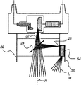
프로젝터(54)는 다수의 방법으로 콜리메이터(22)에 결합될 수 있다. 도 12a를 참조하면, 프로젝터(54)를 지지하는 하우징(36)이 콜리메이터(22)의 에지를 따라 장착되는 실시예가 도시되어 있다. 콜리메이터 조명(26), 일반적으로 발광 다이오드(LED) 또는 다른 고체 광원은 콜리메이터(22) 내부에 장착된다. x-선에 본질적으로 투명한 미러(24)는 x-선 빔(32)의 방사선 경로(R)와 콜리메이터 조명(26)으로부터 광 경로를 결합한다. 프로젝터 조명(34)은 넓은 각도 범위에 걸쳐 투사될 수 있지만, 광 경로가 방사선 경로(R)로부터 이격되어 있기 때문에 약간의 시차 에러가 있을 수 있다.The
도 12b의 다른 배열은 방사선 경로(R)와 프로젝터 조명(34)의 경로를 정렬하기 위해 두 번째 미러, 양방향 미러(108)를 사용하여 시차 에러 조건을 제거한다. 이 정열은 프로젝터(54)가 넓은 각도 범위에 걸쳐 광을 투사할 수 있게 한다.Another arrangement of FIG. 12B eliminates parallax error conditions using a second mirror,
도 12c의 다른 배열은 프로젝터(54)로 기존의 콜리메이터 조명을 대체한다. 여기서, 프로젝터(54)는 방사선 경로(R)와 정렬되고, 방사선 경로(R)에 대해 센터링 정보를 보여주기 위해 다수의 기능을 수행할 수 있다. 투사의 각도 범위는 도 12b의 실시예에서보다 더 많이 제한되지만 콜리메이터 경로와 수신기 위치는 일정 각도 범위 내에서 표시될 수 있다.Another arrangement of FIG. 12C replaces conventional collimator lighting with
본 발명의 일 실시예에 따르면, 피사체의 방사선 투과 이미지를 획득하기 위한 방사선 촬영 시스템이 제공되며, 본 시스템은 방사선 경로를 따라 방사선 에너지를 지향시키도록 활성화될 수 있는 방사선 소스; 방사선 투과 이미지를 형성하기 위해 상기 방사선 에너지에 민감한 이미징 수신기; 적어도 상기 이미징 수신기의 윤곽을 나타내는 하나 이상의 출력 신호를 제공하도록 배치된 센서 장치; 및 상기 하나 이상의 출력 신호에 응답하여 적어도 상기 이미징 수신기의 윤곽을 투사에 의하여 또는 디스플레이 모니터에서 생성하는 디스플레이 장치를 포함한다.According to one embodiment of the invention, there is provided a radiographic system for obtaining a radiographic image of a subject, the system comprising: a radiation source that can be activated to direct radiation energy along a radiation path; An imaging receiver sensitive to the radiation energy to form a radiation transmission image; A sensor device arranged to provide at least one output signal delineating at least the imaging receiver; And a display device for producing at least a contour of the imaging receiver by projection or on a display monitor in response to the one or more output signals.
본 발명의 다른 실시예에 따르면, 피사체의 방사선 투과 이미지를 획득하기 위한 방사선 촬영 시스템이 제공되며, 본 시스템은 방사선 경로를 따라 방사선 에너지를 지향시키도록 활성화될 수 있는 방사선 소스; 상기 방사선 투과 이미지를 형성하기 위해 상기 방사선 에너지에 민감한 이미징 수신기; 적어도 상기 방사선 경로에 대한 상기 수신기의 각도와 상기 방사선 경로를 따른 이미지-소스간 거리를 나타내는 하나 이상의 출력 신호를 제공하도록 배치된 센서 장치; 및 상기 하나 이상의 출력 신호에 응답하여, 적어도 상기 소스-이미지간 거리와 상기 방사선 경로에 대한 상기 수신기의 각도를 나타내는 하나 이상의 값을 제공하는 디스플레이를 생성하는 디스플레이 장치를 포함한다. 디스플레이는 프로젝터 또는 디스플레이 스크린 또는 프로젝터와 디스플레이 장치의 조합 중 어느 것을 사용할 수 있다. 콜리메이터 블레이드 위치 정보를 이용할 수 있는 경우에는, 디스플레이는 또한 방사선 경로를 따라 방사선의 경계를 검출기 윤곽으로 정렬하는 것을 나타낼 수 있다.According to another embodiment of the present invention, there is provided a radiographic system for obtaining a radiographic image of a subject, the system comprising: a radiation source that can be activated to direct radiation energy along a radiation path; An imaging receiver sensitive to the radiation energy to form the radiation transmission image; A sensor device arranged to provide at least one output signal indicative of at least an angle of the receiver to the radiation path and an image-source distance along the radiation path; And in response to the one or more output signals, a display device for generating a display that provides at least one value representing at least the source-image distance and the angle of the receiver to the radiation path. The display can use either a projector or a display screen or a combination of a projector and a display device. If collimator blade position information is available, the display may also indicate aligning the boundary of the radiation with the detector contour along the radiation path.
Claims (10)
방사선 경로를 따라 방사선 에너지를 지향시키도록 활성화될 수 있는 방사선 소스;
방사선 투과 이미지를 형성하기 위해 상기 방사선 에너지에 민감한 이미징 수신기(imaging receiver);
적어도 상기 수신기에 대한 상기 방사선 경로의 센터링, 상기 방사선 경로에 대한 상기 수신기의 각도, 및 상기 방사선 경로를 따른 소스-이미지간 거리를 나타내는 하나 이상의 출력 신호를 제공하도록 배치된 센서 장치; 및
상기 하나 이상의 출력 신호에 응답하여, 상기 수신기에 대한 상기 방사선 경로의 센터링을 나타내고, 또한 적어도 상기 소스-이미지간 거리와 상기 방사선 경로에 대한 상기 수신기의 각도를 나타내는 하나 이상의 값을 제공하는 디스플레이를 생성하는 디스플레이 장치를 포함하는 방사선 촬영 시스템.
A radiographic system for obtaining a radiographic image of a subject,
A radiation source that can be activated to direct radiation energy along a radiation path;
An imaging receiver sensitive to the radiation energy to form a radiation transmission image;
A sensor device arranged to provide one or more output signals indicative of at least centering of the radiation path with respect to the receiver, angle of the receiver with respect to the radiation path, and source-image distance along the radiation path; And
In response to the one or more output signals, generate a display indicative of the centering of the radiation path with respect to the receiver and also provide at least one value representing at least the source-image distance and the angle of the receiver with respect to the radiation path. Radiography system comprising a display device.
상기 디스플레이 장치는 상기 이미징 수신기의 윤곽을 더 나타내는 것인 방사선 촬영 시스템.
The method of claim 1,
And the display device further represents the contour of the imaging receiver.
상기 디스플레이 장치는 소스-물체간 거리 또는 상기 소스-이미지간 거리와 상기 소스-물체간 거리의 조합을 나타내는 값을 더 제공하며, 상기 디스플레이는 상기 소스-물체간 거리의 표현에 기초하여 수정되는 것인 방사선 촬영 시스템.
The method of claim 1,
The display device further provides a value indicating a source-to-object distance or a combination of the source-to-image distance and the source-to-object distance, wherein the display is modified based on the representation of the source-to-object distance Radiography system.
상기 디스플레이 장치는 상기 방사선 소스에 결합된 프로젝터를 포함하는 것인 방사선 촬영 시스템.
The method of claim 1,
And said display device comprises a projector coupled to said radiation source.
상기 디스플레이 장치는 디스플레이 모니터를 포함하며, 상기 디스플레이 모니터는 상기 방사선 소스를 지지하는 붐 조립체(boom assembly)를 따라 배치되고, 상기 디스플레이 모니터는 터치 스크린 모니터를 포함하는 것인 방사선 촬영 시스템.
The method of claim 1,
Wherein said display device comprises a display monitor, said display monitor being disposed along a boom assembly supporting said radiation source, said display monitor comprising a touch screen monitor.
상기 이미징 수신기는 필름 카세트, 계산된 방사선 촬영 카세트(computed radiography cassette) 및 디지털 방사선 촬영 카세트로 구성된 군으로부터 취해지고, 상기 센서 장치는 전자기장 또는 전자기 신호를 감지하며, 상기 센서 장치는 경사계를 포함하고, 상기 센서 장치는 상기 수신기의 일부이거나 상기 수신기에 결합된 홀더의 일부이며, 상기 센서 장치로부터의 상기 하나 이상의 출력 신호는 상기 이미징 수신기에서 사용되는 그리드에 대한 정보를 더 제공하는 것인 방사선 촬영 시스템.
The method of claim 1,
The imaging receiver is taken from a group consisting of a film cassette, a computed radiography cassette and a digital radiography cassette, the sensor device detecting an electromagnetic field or an electromagnetic signal, the sensor device comprising an inclinometer, The sensor device is part of the receiver or part of a holder coupled to the receiver, wherein the one or more output signals from the sensor device further provide information about a grid used in the imaging receiver.
방사선 경로를 따라 방사선 에너지를 지향시키도록 활성화될 수 있는 방사선 소스;
디지털 이미지로서 방사선 투과 이미지를 형성하기 위해 상기 방사선 에너지에 민감한 이미징 수신기;
적어도 상기 이미징 수신기의 윤곽, 상기 수신기에 대한 상기 방사선 경로의 센터링, 상기 방사선 경로에 대한 상기 수신기의 각도, 및 상기 방사선 경로를 따른 소스-이미지간 거리를 나타내는 하나 이상의 출력 신호를 제공하도록 배치된 센서 장치; 및
상기 하나 이상의 출력 신호에 응답하여, 상기 이미징 수신기의 윤곽과 상기 수신기에 대한 상기 방사선 경로의 센터링을 나타내고, 적어도 상기 소스-이미지 간 거리와 상기 방사선 경로에 대한 상기 수신기의 각도를 나타내는 하나 이상의 수치 값을 디스플레이하는 디스플레이를 생성하는 디스플레이 장치를 포함하는 방사선 촬영 시스템.
A radiographic system for obtaining a radiographic image of a subject,
A radiation source that can be activated to direct radiation energy along a radiation path;
An imaging receiver sensitive to the radiation energy for forming a radiation transmission image as a digital image;
A sensor arranged to provide one or more output signals indicative of at least the contour of the imaging receiver, the centering of the radiation path with respect to the receiver, the angle of the receiver with respect to the radiation path, and the source-image distance along the radiation path. Device; And
One or more numerical values indicative of the contour of the imaging receiver and the centering of the radiation path relative to the receiver in response to the one or more output signals, the at least one source-image distance and the angle of the receiver relative to the radiation path A radiography system comprising a display device for generating a display for displaying a display.
방사선 소스로부터 방사선 경로에 대한 이미징 수신기의 센터링, 상기 방사선 경로에 대한 상기 수신기의 각도, 및 상기 방사선 경로를 따른 소스-이미지간 거리를 나타내는 하나 이상의 신호를 획득하는 단계; 및
상기 하나 이상의 획득된 신호에 응답하여, 적어도 상기 이미징 수신기의 센터링을 나타내고 상기 소스-이미지간 거리 또는 상기 각도 또는 이들 둘 모두를 나타내는 하나 이상의 값을 디스플레이하는 디스플레이를 생성하는 단계를 포함하는, 방사선 투과 이미지를 획득하기 위한 방법.
A method for obtaining a radiographic image of a subject,
Obtaining one or more signals indicative of the centering of the imaging receiver relative to the radiation path from the radiation source, the angle of the receiver relative to the radiation path, and the source-image distance along the radiation path; And
In response to the one or more acquired signals, generating a display indicative of at least the centering of the imaging receiver and displaying one or more values indicative of the source-image distance or the angle or both. Method for Acquiring an Image.
상기 디스플레이를 생성하는 단계는 상기 피사체 쪽으로 이미지를 투사하거나 디스플레이 스크린에 디스플레이를 형성하는 단계를 포함하는 것인, 방사선 투과 이미지를 획득하기 위한 방법.
9. The method of claim 8,
Generating the display comprises projecting an image towards the subject or forming a display on a display screen.
상기 하나 이상의 신호로부터 획득된 정보를 상기 이미지 데이터와 함께 저장하는 단계;
뷰 유형(view type)을 지정하는 오퍼레이터 지시를 획득하고 상기 뷰 유형에 따라 상기 소스-이미지간 거리 또는 상기 각도 또는 이들 둘 모두를 나타내는 미리 결정된 값을 디스플레이하는 단계; 및
상기 수신기에 대한 상기 방사선 소스의 각도 배향에 따라 상기 디스플레이를 재배향하는 단계를 더 포함하며,
상기 하나 이상의 신호를 획득하는 단계는 상기 방사선 소스의 콜리메이터에 결합된 프로젝터의 초점을 위해 사용되는 신호를 획득하는 단계를 더 포함하고,
상기 하나 이상의 신호를 획득하는 단계는 그리드 유형을 나타내는 신호를 획득하는 단계를 더 포함하며, 하나 이상의 값을 디스플레이하는 단계는 상기 그리드 유형에 대한 정보를 사용하는 단계를 포함하는 것인, 방사선 투과 이미지를 획득하기 위한 방법.9. The method of claim 8,
Storing the information obtained from the one or more signals together with the image data;
Obtaining an operator indication specifying a view type and displaying a predetermined value indicative of the source-image distance or the angle or both depending on the view type; And
Reorienting the display according to the angular orientation of the radiation source with respect to the receiver,
Acquiring the one or more signals further comprises acquiring a signal used for focusing a projector coupled to a collimator of the radiation source,
Acquiring the one or more signals further comprises acquiring a signal indicative of a grid type, and displaying one or more values comprises using information about the grid type. Method for obtaining
Applications Claiming Priority (7)
| Application Number | Priority Date | Filing Date | Title |
|---|---|---|---|
| US32347610P | 2010-04-13 | 2010-04-13 | |
| US61/323,476 | 2010-04-13 | ||
| US201161449932P | 2011-03-07 | 2011-03-07 | |
| US61/449,932 | 2011-03-07 | ||
| US13/083,860 | 2011-04-11 | ||
| US13/083,860 US8827554B2 (en) | 2010-04-13 | 2011-04-11 | Tube alignment for mobile radiography system |
| PCT/US2011/032020 WO2011130198A2 (en) | 2010-04-13 | 2011-04-12 | Tube alignment for mobile radiography system |
Publications (1)
| Publication Number | Publication Date |
|---|---|
| KR20130057991A true KR20130057991A (en) | 2013-06-03 |
Family
ID=52358433
Family Applications (1)
| Application Number | Title | Priority Date | Filing Date |
|---|---|---|---|
| KR1020127029132A KR20130057991A (en) | 2010-04-13 | 2011-04-12 | Tube alignment for mobile radiography system |
Country Status (6)
| Country | Link |
|---|---|
| US (2) | US8827554B2 (en) |
| EP (1) | EP2557997B1 (en) |
| JP (1) | JP2013523396A (en) |
| KR (1) | KR20130057991A (en) |
| CN (1) | CN102917646B (en) |
| WO (1) | WO2011130198A2 (en) |
Cited By (3)
| Publication number | Priority date | Publication date | Assignee | Title |
|---|---|---|---|---|
| KR20170009685A (en) * | 2015-07-17 | 2017-01-25 | 주식회사 레이언스 | Operation method for x-ray photographing apparatus and operation program thereof |
| US10098609B2 (en) | 2014-12-12 | 2018-10-16 | Samsung Electronics Co., Ltd. | X ray apparatus and method of operating the same |
| US10188365B2 (en) | 2015-06-23 | 2019-01-29 | Samsung Electronics Co., Ltd. | X-ray apparatus and controlling method of the same |
Families Citing this family (44)
| Publication number | Priority date | Publication date | Assignee | Title |
|---|---|---|---|---|
| US9770366B2 (en) | 2009-07-15 | 2017-09-26 | Tusker Medical, Inc. | Tympanic membrane pressure equalization tube delivery system |
| WO2011141763A1 (en) * | 2010-05-12 | 2011-11-17 | Trophy | Alignment apparatus for dental intraoral radiography |
| US9161727B2 (en) | 2011-09-01 | 2015-10-20 | Hologic Inc | Independently rotatable detector plate for medical imaging device |
| IN2014CN03653A (en) * | 2011-11-18 | 2015-10-09 | Koninkl Philips Nv | |
| US9028145B2 (en) * | 2011-11-25 | 2015-05-12 | Aribex, Inc. | Apparatus and methods for collimation of X-rays |
| ES2658965T3 (en) | 2012-02-22 | 2018-03-13 | Carestream Health, Inc. | Mobile radiographic devices / procedures capable of tomosynthesis |
| WO2014043412A1 (en) * | 2012-09-12 | 2014-03-20 | Baek Seung H | Method and apparatus for more accurate positioning of dental imaging equipment |
| WO2014102718A1 (en) * | 2012-12-28 | 2014-07-03 | Koninklijke Philips N.V. | Real-time scene-modeling combining 3d ultrasound and 2d x-ray imagery |
| US20140198900A1 (en) * | 2013-01-17 | 2014-07-17 | Palo Alto Research Center Incorporated | High resolution x-ray imaging with thin, flexible digital sensors |
| JP6176832B2 (en) * | 2013-04-18 | 2017-08-09 | 東芝メディカルシステムズ株式会社 | Support device and X-ray diagnostic apparatus |
| JP6196728B2 (en) | 2013-04-23 | 2017-09-13 | コーニンクレッカ フィリップス エヌ ヴェKoninklijke Philips N.V. | Tube-detector alignment using light projection |
| CN104173066B (en) * | 2013-07-31 | 2015-09-02 | 上海联影医疗科技有限公司 | Detect the method for X-ray shooting system source image distance |
| CN105473074B (en) | 2013-08-05 | 2019-06-14 | 皇家飞利浦有限公司 | Pipe alignment function for mobile radiographic system |
| JP6381966B2 (en) * | 2014-05-14 | 2018-08-29 | キヤノンメディカルシステムズ株式会社 | Medical diagnostic imaging equipment |
| DE102015205096A1 (en) * | 2014-05-19 | 2015-11-19 | Siemens Aktiengesellschaft | Visualization of an X-ray area |
| WO2016026817A1 (en) * | 2014-08-19 | 2016-02-25 | Koninklijke Philips N.V. | X-ray imaging apparatus |
| KR102328118B1 (en) | 2014-11-24 | 2021-11-18 | 삼성전자주식회사 | X ray apparatus and system |
| KR102340197B1 (en) * | 2015-02-03 | 2021-12-16 | 삼성전자주식회사 | X ray apparatus and method of oprating the same |
| JP6412815B2 (en) * | 2015-02-26 | 2018-10-24 | 富士フイルム株式会社 | Radiographic imaging system, imaging table, and imaging method |
| WO2016195684A1 (en) * | 2015-06-04 | 2016-12-08 | Siemens Healthcare Gmbh | Apparatus and methods for a projection display device on x-ray imaging devices |
| CN107708569B (en) * | 2015-06-22 | 2021-01-12 | 富士胶片株式会社 | Radiation irradiation apparatus, control method for radiation irradiation apparatus, and storage medium |
| KR101798939B1 (en) | 2015-09-08 | 2017-11-17 | 삼성전자주식회사 | X-ray image apparatus and control method for the same |
| US10556129B2 (en) * | 2015-10-02 | 2020-02-11 | Varian Medical Systems, Inc. | Systems and methods for treating a skin condition using radiation |
| FR3044200B1 (en) * | 2015-11-23 | 2020-07-03 | Trixell | RADIOLOGY ASSEMBLY AND METHOD FOR ALIGNING SUCH AN ASSEMBLY |
| EP3235431B1 (en) * | 2016-04-19 | 2019-02-27 | Agfa Nv | Radiation image capturing system and method |
| CN107874768B (en) * | 2016-09-30 | 2021-02-05 | 通用电气公司 | Mobile radiation imaging system and alignment method thereof |
| WO2018109127A1 (en) * | 2016-12-15 | 2018-06-21 | Koninklijke Philips N.V. | Visualizing collimation errors |
| US11103205B2 (en) | 2017-03-27 | 2021-08-31 | Carestream Health, Inc. | Bedside dynamic imaging |
| US10568602B2 (en) | 2017-09-06 | 2020-02-25 | General Electric Company | Virtual positioning image for use in imaging |
| US10531850B2 (en) | 2017-09-07 | 2020-01-14 | General Electric Company | Mobile X-ray imaging with detector docking within a spatially registered compartment |
| EP3473186A1 (en) * | 2017-10-18 | 2019-04-24 | Koninklijke Philips N.V. | Radiation target indication |
| KR102190031B1 (en) * | 2017-11-07 | 2020-12-11 | 삼성전자주식회사 | X-ray image apparatus and control method for the same |
| CN107990853B (en) * | 2018-01-03 | 2019-11-22 | 东软医疗系统股份有限公司 | A kind of source image distance detecting method and device |
| JP7243090B2 (en) * | 2018-09-10 | 2023-03-22 | コニカミノルタ株式会社 | radiography system |
| WO2020067323A1 (en) * | 2018-09-27 | 2020-04-02 | 富士フイルム株式会社 | Radiation imaging device |
| CN111096759A (en) * | 2018-10-26 | 2020-05-05 | 深圳迈瑞生物医疗电子股份有限公司 | X-ray photography system, flat panel detector thereof and related method |
| EP3936052A1 (en) * | 2020-07-07 | 2022-01-12 | Koninklijke Philips N.V. | User interface for x-ray tube-detector alignment |
| US11779290B2 (en) | 2020-10-09 | 2023-10-10 | Shimadzu Corporation | X-ray imaging system and x-ray imaging apparatus |
| JP7484703B2 (en) * | 2020-12-25 | 2024-05-16 | 株式会社島津製作所 | X-ray imaging device and position deviation detection unit for X-ray imaging device |
| WO2022203896A1 (en) * | 2021-03-23 | 2022-09-29 | Carestream Health, Inc. | Physiological analysis from video x-ray imaging |
| US20220326165A1 (en) * | 2021-04-07 | 2022-10-13 | Jst Power Equipment, Inc. | Rapid x-ray radiation imaging system and mobile imaging system |
| US11382582B1 (en) | 2021-08-02 | 2022-07-12 | Oxos Medical, Inc. | Imaging systems and methods |
| KR102378300B1 (en) * | 2021-08-05 | 2022-03-25 | 주식회사 포스콤 | X-ray device |
| CN114531767B (en) * | 2022-04-20 | 2022-08-02 | 深圳市宝润科技有限公司 | Visual X-ray positioning method and system for handheld X-ray machine |
Family Cites Families (57)
| Publication number | Priority date | Publication date | Assignee | Title |
|---|---|---|---|---|
| US4017858A (en) | 1973-07-30 | 1977-04-12 | Polhemus Navigation Sciences, Inc. | Apparatus for generating a nutating electromagnetic field |
| DE2817391A1 (en) | 1978-04-20 | 1979-10-31 | Siemens Ag | X-RAY COLLECTOR |
| US4836671A (en) | 1985-04-08 | 1989-06-06 | Charles Lescrenier | Locating device |
| US4752948A (en) | 1986-12-01 | 1988-06-21 | University Of Chicago | Mobile radiography alignment device |
| US6405072B1 (en) | 1991-01-28 | 2002-06-11 | Sherwood Services Ag | Apparatus and method for determining a location of an anatomical target with reference to a medical apparatus |
| US5241578A (en) | 1991-12-02 | 1993-08-31 | Arch Development Corporation | Optical grid alignment system for portable radiography and portable radiography apparatus incorporating same |
| JP3456718B2 (en) | 1993-01-27 | 2003-10-14 | 株式会社東芝 | X-ray equipment |
| US5388143A (en) | 1993-11-26 | 1995-02-07 | Arch Development Corporation | Alignment method for radiography and radiography apparatus incorporating same |
| US5550889A (en) | 1994-11-28 | 1996-08-27 | General Electric | Alignment of an x-ray tube focal spot using a deflection coil |
| US5617462A (en) | 1995-08-07 | 1997-04-01 | Oec Medical Systems, Inc. | Automatic X-ray exposure control system and method of use |
| US5949811A (en) | 1996-10-08 | 1999-09-07 | Hitachi Medical Corporation | X-ray apparatus |
| US5751783A (en) | 1996-12-20 | 1998-05-12 | General Electric Company | Detector for automatic exposure control on an x-ray imaging system |
| US6175610B1 (en) * | 1998-02-11 | 2001-01-16 | Siemens Aktiengesellschaft | Medical technical system controlled by vision-detected operator activity |
| US6047042A (en) | 1998-03-25 | 2000-04-04 | Continental X-Ray Corporation | Automatic exposure and brightness control for fluoroscopic and radio-graphic imaging |
| JP2000023955A (en) | 1998-07-14 | 2000-01-25 | Canon Inc | Radiograph |
| JP4383558B2 (en) | 1998-07-21 | 2009-12-16 | 東芝医用システムエンジニアリング株式会社 | X-ray diagnostic apparatus and radiation diagnostic apparatus |
| US6192105B1 (en) | 1998-11-25 | 2001-02-20 | Communications & Power Industries Canada Inc. | Method and device to calibrate an automatic exposure control device in an x-ray imaging system |
| US6154522A (en) | 1999-02-11 | 2000-11-28 | Mcdonnell Douglas Corporation | Method, system and apparatus for aiming a device emitting a radiant beam |
| JP2001061861A (en) | 1999-06-28 | 2001-03-13 | Siemens Ag | System having image photographing means and medical work station |
| US6404851B1 (en) | 2000-03-30 | 2002-06-11 | General Electric Company | Method and apparatus for automatic exposure control using localized capacitive coupling in a matrix-addressed imaging panel |
| US6327336B1 (en) | 2000-06-05 | 2001-12-04 | Direct Radiography Corp. | Radiogram showing location of automatic exposure control sensor |
| US6760405B2 (en) | 2000-09-20 | 2004-07-06 | Koninklijke Philips Electronics N.V. | Exposure control in an x-ray image detector |
| JP2002143139A (en) | 2000-11-15 | 2002-05-21 | Fuji Photo Film Co Ltd | Portable radiographic system and radiographic image detector to be used for the system |
| US6422750B1 (en) | 2000-12-22 | 2002-07-23 | Ge Medical Systems Global Technology Company, Llc | Digital x-ray imager alignment method |
| US6702459B2 (en) | 2001-04-11 | 2004-03-09 | The Uab Research Foundation | Mobile radiography system and process |
| US6795526B2 (en) | 2002-03-04 | 2004-09-21 | Ge Medical Systems Global Technology Co., Llc | Automatic exposure control for a digital image acquisition system |
| SE522162C2 (en) | 2002-05-06 | 2004-01-20 | Goergen Nilsson | Dose delivery quantification enabling method for radiotherapy treatment, involves analyzing measurements to obtain information about relation between measurements in phantom and information between phantom and treatment source |
| JP3647440B2 (en) | 2002-05-28 | 2005-05-11 | キヤノン株式会社 | X-ray equipment |
| DE10234465A1 (en) | 2002-07-29 | 2004-02-12 | Siemens Ag | X-ray sectional-imaging method in which the height of a sectional image is set using a camera arrangement for imaging the patient from the side so that a reference marking can be made on a reference image |
| EP1388740B1 (en) | 2002-08-09 | 2014-11-05 | Canon Kabushiki Kaisha | Radiation imaging method and apparatus |
| JP4522044B2 (en) | 2002-11-15 | 2010-08-11 | キヤノン株式会社 | Radiography equipment |
| US6935779B2 (en) * | 2002-11-29 | 2005-08-30 | Ge Medical Systems Global Technology Company, Llc | Method and apparatus for aligning an X-ray source and detector at various source to image distances |
| US6950492B2 (en) | 2003-06-25 | 2005-09-27 | Besson Guy M | Dynamic multi-spectral X-ray projection imaging |
| US7697743B2 (en) | 2003-07-03 | 2010-04-13 | General Electric Company | Methods and systems for prescribing parameters for tomosynthesis |
| US7519155B2 (en) | 2003-10-29 | 2009-04-14 | Koninklijke Philips Electronics N.V. | Device and method for adjusting imaging parameters of an X-ray apparatus |
| JP4612796B2 (en) | 2004-01-30 | 2011-01-12 | キヤノン株式会社 | X-ray imaging image display control apparatus and method, and X-ray imaging system |
| WO2005124866A1 (en) | 2004-06-18 | 2005-12-29 | Koninklijke Philips Electronics N.V. | X-ray image detector |
| FI118356B (en) * | 2004-07-22 | 2007-10-15 | Planmeca Oy | Arrangements in connection with intraoral X-ray imaging |
| JP4560359B2 (en) | 2004-09-13 | 2010-10-13 | オリンパス株式会社 | Position detection apparatus, in-subject introduction system, and position detection method |
| US7581885B2 (en) | 2004-11-24 | 2009-09-01 | General Electric Company | Method and system of aligning x-ray detector for data acquisition |
| KR100972253B1 (en) | 2004-12-17 | 2010-07-23 | 올림푸스 가부시키가이샤 | Position-detection system for medical use using magnetic-induction |
| DE102005036852A1 (en) * | 2005-08-04 | 2007-02-22 | Siemens Ag | A method or "device" for determining a position of a patient in a based on a medical imaging method creating an image of an examination area of the patient |
| EP1926426B1 (en) | 2005-09-08 | 2014-10-08 | Philips Intellectual Property & Standards GmbH | Magnetic tracking system for an imaging system |
| JP4597936B2 (en) | 2005-10-06 | 2010-12-15 | 富士フイルム株式会社 | Breast imaging device |
| US7581884B1 (en) | 2006-02-07 | 2009-09-01 | Barnes Gary T | Mobile radiography system and grid alignment process |
| FR2899349B1 (en) | 2006-04-04 | 2009-05-01 | Pierre Tranchant | POSITION ADJUSTMENT OF A MOBILE RADIOLOGY INSTALLATION |
| US7313224B1 (en) | 2006-06-22 | 2007-12-25 | General Electric Co. | Wireless integrated automatic exposure control module |
| US20090180590A1 (en) | 2006-06-22 | 2009-07-16 | Koninklijke Philips Electronics N.V. | X-ray image apparatus and method of imaging an object under examination |
| EP2057637A2 (en) | 2006-08-21 | 2009-05-13 | Philips Intellectual Property & Standards GmbH | Portable x-ray detector with grid sensing unit and x-ray imaging system for automatic exposure setting for the portable x-ray detector |
| US7744279B2 (en) | 2006-11-02 | 2010-06-29 | Carestream Health, Inc. | Orientation sensing apparatus for radiation imaging system |
| JP2008125981A (en) * | 2006-11-24 | 2008-06-05 | Shimadzu Corp | Universal photography system |
| JP5196798B2 (en) | 2007-02-15 | 2013-05-15 | キヤノン株式会社 | Radiation image projection apparatus and method |
| US7734013B2 (en) | 2007-03-26 | 2010-06-08 | Fujifilm Corporation | Radiation image capturing apparatus and method of controlling radiation image capturing apparatus |
| US20090086926A1 (en) * | 2007-09-27 | 2009-04-02 | Carestream Health, Inc. | Exposure centering apparatus for imaging system |
| JP2009131323A (en) * | 2007-11-28 | 2009-06-18 | Canon Inc | Imaging apparatus |
| WO2009097323A2 (en) | 2008-01-28 | 2009-08-06 | Reflective X-Ray Optics Llc | Optical alignment system and alignment method for radiographic x-ray imaging |
| US7632016B1 (en) | 2008-07-22 | 2009-12-15 | Carestream Health, Inc. | Digital detector calibration with known exposure |
-
2011
- 2011-04-11 US US13/083,860 patent/US8827554B2/en active Active
- 2011-04-12 KR KR1020127029132A patent/KR20130057991A/en not_active Application Discontinuation
- 2011-04-12 CN CN201180027634.0A patent/CN102917646B/en active Active
- 2011-04-12 WO PCT/US2011/032020 patent/WO2011130198A2/en active Application Filing
- 2011-04-12 EP EP11769395.2A patent/EP2557997B1/en not_active Not-in-force
- 2011-04-12 JP JP2013505031A patent/JP2013523396A/en not_active Withdrawn
-
2014
- 2014-07-31 US US14/447,695 patent/US9155509B2/en active Active
Cited By (3)
| Publication number | Priority date | Publication date | Assignee | Title |
|---|---|---|---|---|
| US10098609B2 (en) | 2014-12-12 | 2018-10-16 | Samsung Electronics Co., Ltd. | X ray apparatus and method of operating the same |
| US10188365B2 (en) | 2015-06-23 | 2019-01-29 | Samsung Electronics Co., Ltd. | X-ray apparatus and controlling method of the same |
| KR20170009685A (en) * | 2015-07-17 | 2017-01-25 | 주식회사 레이언스 | Operation method for x-ray photographing apparatus and operation program thereof |
Also Published As
| Publication number | Publication date |
|---|---|
| CN102917646A (en) | 2013-02-06 |
| JP2013523396A (en) | 2013-06-17 |
| US9155509B2 (en) | 2015-10-13 |
| CN102917646B (en) | 2015-10-21 |
| WO2011130198A2 (en) | 2011-10-20 |
| WO2011130198A3 (en) | 2012-01-19 |
| US20140341349A1 (en) | 2014-11-20 |
| US20110249793A1 (en) | 2011-10-13 |
| US8827554B2 (en) | 2014-09-09 |
| EP2557997A2 (en) | 2013-02-20 |
| EP2557997B1 (en) | 2015-08-05 |
| EP2557997A4 (en) | 2014-04-09 |
Similar Documents
| Publication | Publication Date | Title |
|---|---|---|
| US9155509B2 (en) | Tube alignment for mobile radiography system | |
| US8821017B2 (en) | Projector as collimator light | |
| US8670521B2 (en) | Method for generating an intraoral volume image | |
| KR101664528B1 (en) | Alignment apparatus for dental intraoral radiography | |
| US7114849B2 (en) | Medical imaging device | |
| US9179886B2 (en) | Alignment apparatus for x-ray imaging system | |
| US7581884B1 (en) | Mobile radiography system and grid alignment process | |
| US20090041201A1 (en) | Alignment apparatus for imaging system | |
| US7806591B2 (en) | Alignment apparatus for imaging system using reflective element | |
| US7014362B2 (en) | Device for determining relative positions of an X-ray source and an image receiver | |
| CN105142525A (en) | Tube-detector alignment using light projections | |
| JP5442381B2 (en) | Medical imaging system | |
| US11612371B2 (en) | Radiation tracking for portable fluoroscopy x-ray imaging system | |
| JP5027711B2 (en) | Radiation imaging apparatus and method, and program | |
| JP2005160545A (en) | Digital x-ray tomography system | |
| KR20210045599A (en) | Detecting system of medical radiation and method for detecting medical radiation using the same |
Legal Events
| Date | Code | Title | Description |
|---|---|---|---|
| WITN | Application deemed withdrawn, e.g. because no request for examination was filed or no examination fee was paid |