KR20130016277A - Interactive display system - Google Patents
Interactive display system Download PDFInfo
- Publication number
- KR20130016277A KR20130016277A KR1020127026764A KR20127026764A KR20130016277A KR 20130016277 A KR20130016277 A KR 20130016277A KR 1020127026764 A KR1020127026764 A KR 1020127026764A KR 20127026764 A KR20127026764 A KR 20127026764A KR 20130016277 A KR20130016277 A KR 20130016277A
- Authority
- KR
- South Korea
- Prior art keywords
- pixel
- positioning object
- display
- image frame
- positioning
- Prior art date
Links
Images


Classifications
-
- G—PHYSICS
- G06—COMPUTING; CALCULATING OR COUNTING
- G06F—ELECTRIC DIGITAL DATA PROCESSING
- G06F3/00—Input arrangements for transferring data to be processed into a form capable of being handled by the computer; Output arrangements for transferring data from processing unit to output unit, e.g. interface arrangements
- G06F3/01—Input arrangements or combined input and output arrangements for interaction between user and computer
- G06F3/03—Arrangements for converting the position or the displacement of a member into a coded form
- G06F3/033—Pointing devices displaced or positioned by the user, e.g. mice, trackballs, pens or joysticks; Accessories therefor
- G06F3/0354—Pointing devices displaced or positioned by the user, e.g. mice, trackballs, pens or joysticks; Accessories therefor with detection of 2D relative movements between the device, or an operating part thereof, and a plane or surface, e.g. 2D mice, trackballs, pens or pucks
- G06F3/03542—Light pens for emitting or receiving light
-
- G—PHYSICS
- G06—COMPUTING; CALCULATING OR COUNTING
- G06F—ELECTRIC DIGITAL DATA PROCESSING
- G06F3/00—Input arrangements for transferring data to be processed into a form capable of being handled by the computer; Output arrangements for transferring data from processing unit to output unit, e.g. interface arrangements
- G06F3/01—Input arrangements or combined input and output arrangements for interaction between user and computer
- G06F3/03—Arrangements for converting the position or the displacement of a member into a coded form
- G06F3/0304—Detection arrangements using opto-electronic means
- G06F3/0317—Detection arrangements using opto-electronic means in co-operation with a patterned surface, e.g. absolute position or relative movement detection for an optical mouse or pen positioned with respect to a coded surface
- G06F3/0321—Detection arrangements using opto-electronic means in co-operation with a patterned surface, e.g. absolute position or relative movement detection for an optical mouse or pen positioned with respect to a coded surface by optically sensing the absolute position with respect to a regularly patterned surface forming a passive digitiser, e.g. pen optically detecting position indicative tags printed on a paper sheet
-
- G—PHYSICS
- G06—COMPUTING; CALCULATING OR COUNTING
- G06F—ELECTRIC DIGITAL DATA PROCESSING
- G06F3/00—Input arrangements for transferring data to be processed into a form capable of being handled by the computer; Output arrangements for transferring data from processing unit to output unit, e.g. interface arrangements
- G06F3/01—Input arrangements or combined input and output arrangements for interaction between user and computer
- G06F3/03—Arrangements for converting the position or the displacement of a member into a coded form
- G06F3/033—Pointing devices displaced or positioned by the user, e.g. mice, trackballs, pens or joysticks; Accessories therefor
- G06F3/0346—Pointing devices displaced or positioned by the user, e.g. mice, trackballs, pens or joysticks; Accessories therefor with detection of the device orientation or free movement in a 3D space, e.g. 3D mice, 6-DOF [six degrees of freedom] pointers using gyroscopes, accelerometers or tilt-sensors
-
- G—PHYSICS
- G06—COMPUTING; CALCULATING OR COUNTING
- G06F—ELECTRIC DIGITAL DATA PROCESSING
- G06F3/00—Input arrangements for transferring data to be processed into a form capable of being handled by the computer; Output arrangements for transferring data from processing unit to output unit, e.g. interface arrangements
- G06F3/01—Input arrangements or combined input and output arrangements for interaction between user and computer
- G06F3/03—Arrangements for converting the position or the displacement of a member into a coded form
- G06F3/033—Pointing devices displaced or positioned by the user, e.g. mice, trackballs, pens or joysticks; Accessories therefor
- G06F3/038—Control and interface arrangements therefor, e.g. drivers or device-embedded control circuitry
- G06F3/0386—Control and interface arrangements therefor, e.g. drivers or device-embedded control circuitry for light pen
-
- G—PHYSICS
- G06—COMPUTING; CALCULATING OR COUNTING
- G06F—ELECTRIC DIGITAL DATA PROCESSING
- G06F3/00—Input arrangements for transferring data to be processed into a form capable of being handled by the computer; Output arrangements for transferring data from processing unit to output unit, e.g. interface arrangements
- G06F3/14—Digital output to display device ; Cooperation and interconnection of the display device with other functional units
-
- G—PHYSICS
- G06—COMPUTING; CALCULATING OR COUNTING
- G06T—IMAGE DATA PROCESSING OR GENERATION, IN GENERAL
- G06T1/00—General purpose image data processing
-
- H—ELECTRICITY
- H04—ELECTRIC COMMUNICATION TECHNIQUE
- H04N—PICTORIAL COMMUNICATION, e.g. TELEVISION
- H04N9/00—Details of colour television systems
- H04N9/12—Picture reproducers
- H04N9/31—Projection devices for colour picture display, e.g. using electronic spatial light modulators [ESLM]
- H04N9/3179—Video signal processing therefor
- H04N9/3182—Colour adjustment, e.g. white balance, shading or gamut
-
- H—ELECTRICITY
- H04—ELECTRIC COMMUNICATION TECHNIQUE
- H04N—PICTORIAL COMMUNICATION, e.g. TELEVISION
- H04N9/00—Details of colour television systems
- H04N9/12—Picture reproducers
- H04N9/31—Projection devices for colour picture display, e.g. using electronic spatial light modulators [ESLM]
- H04N9/3191—Testing thereof
- H04N9/3194—Testing thereof including sensor feedback
Landscapes
- Engineering & Computer Science (AREA)
- Theoretical Computer Science (AREA)
- General Engineering & Computer Science (AREA)
- General Physics & Mathematics (AREA)
- Physics & Mathematics (AREA)
- Human Computer Interaction (AREA)
- Signal Processing (AREA)
- Multimedia (AREA)
- Controls And Circuits For Display Device (AREA)
- Position Input By Displaying (AREA)
- User Interface Of Digital Computer (AREA)
- Image Processing (AREA)
- Two-Way Televisions, Distribution Of Moving Picture Or The Like (AREA)
- Closed-Circuit Television Systems (AREA)
Abstract
카메라 또는 기타 비디오 캡처 시스템을 포함하는 무선 포인팅 장치를 포함하는 대화형 디스플레이 시스템. 포인팅 장치는 컴퓨터에 의해 디스플레이되는 영상 - 하나 이상의 사람이 인지할 수 없는 위치 확인 대상물을 포함함 - 을 캡처한다. 위치 확인 대상물은 시각적 페이로드의 디스플레이 프레임에서의 강도의 패턴화된 변조(예컨대, 픽셀 강도의 변동) 및 그에 뒤이은 연속적인 프레임에서의 정반대 변조로서 제시된다. 캡처된 시각적 데이터에서 위치 확인 대상물을 복원하기 위해 그리고 디스플레이된 영상 페이로드를 제거하기 위해, 적어도 2개의 캡처된 영상 프레임이 서로로부터 차감된다. 복원된 위치 확인 대상물의 위치, 크기 및 배향은 디스플레이에 대한 원격 포인팅 장치의 조준점을 식별해준다. 다른 실시예는 포인팅 장치의 위치를 확인하기 위해 위치 확인 대상물(사람이 인지할 수 있거나 사람이 인지할 수 없음)의 시간 시퀀싱(temporal sequencing)을 사용한다.Interactive display system comprising a wireless pointing device including a camera or other video capture system. The pointing device captures an image displayed by the computer, including a positioning object that one or more people cannot recognize. The positioning object is presented as a patterned modulation of intensity in the display frame of the visual payload (eg, variation in pixel intensity) followed by the opposite modulation in successive frames. At least two captured image frames are subtracted from each other to restore the positioning object in the captured visual data and to remove the displayed image payload. The position, size and orientation of the restored positioning object identifies the aiming point of the remote pointing device to the display. Another embodiment uses temporal sequencing of the positioning object (either human or human not) to locate the pointing device.
Description
본 발명은 대화형 디스플레이 시스템의 분야이다. 본 발명의 실시예는 보다 구체적으로는 사용자가 원격 핸드헬드 장치를 사용하여 디스플레이된 콘텐츠와 상호작용하는 이러한 디스플레이 시스템, 및 이를 동작시키는 방법에 관한 것이다.The present invention is in the field of interactive display systems. Embodiments of the present invention more specifically relate to such a display system and a method of operating the user in which the user interacts with the displayed content using a remote handheld device.
연설자가 메시지를 청중에게 전달하는 능력은 말소리(spoken word)와 함께 시각적 정보를 사용하는 것에 의해 일반적으로 향상된다. 최근에, 시각적 정보를 발생하여 청중에게 디스플레이하기 위해 컴퓨터 및 관련 디스플레이 시스템을 사용하는 일이, 예를 들어, Microsoft Corporation으로부터 입수가능한 POWERPOINT 프레젠테이션 소프트웨어 프로그램 등의 응용 프로그램에 의해 흔해지게 되었다. 강당 환경에서와 같이 대규모 청중의 경우, 디스플레이 시스템은 일반적으로 프로젝션 시스템(전면 프로젝션 또는 후면 프로젝션)이다. 회의실 또는 교실 환경에서와 같이 소규모 청중의 경우, 평판(예컨대, 액정) 디스플레이가 널리 사용되고 있는데, 그 이유는 특히 이들 디스플레이의 가격이 최근 수년에 걸쳐 떨어졌기 때문이다. 특수한 화면을 필요로 하지 않고 따라서 훨씬 더 쉽게 배포되는 소형 프로젝터("피코-프로젝터") 등의 새로운 디스플레이 기술이 이제 시중에 나오고 있다. 아주 소규모의 청중(예컨대, 한 사람 또는 두 사람)에 대한 프레젠테이션의 경우, 시각적 정보를 제시하기 위해 랩톱 컴퓨터의 그래픽 디스플레이로 충분할 수 있다. 어쨋든, 향상되는 컴퓨터 능력과 고품질의 대형 디스플레이의 결합에 의해, 보다 적은 비용으로, 아주 광범위한 상황(예컨대, 사업, 교육, 법률, 엔터테인먼트)에서 컴퓨터-기반 프레젠테이션 시스템의 사용이 증가되었다.The ability of a speaker to deliver a message to an audience is generally improved by using visual information in conjunction with spoken words. Recently, the use of computers and associated display systems to generate and display visual information to an audience has become commonplace, for example, by applications such as the POWERPOINT presentation software program available from Microsoft Corporation. For large audiences, such as in an auditorium environment, the display system is typically a projection system (front projection or rear projection). For small audiences, such as in a conference room or classroom environment, flat panel (e.g., liquid crystal) displays are widely used, especially since the prices of these displays have fallen over recent years. New display technologies are now on the market, such as small projectors ("pico-projectors") that do not require a special screen and are therefore much easier to deploy. For presentations to a very small audience (eg one or two people), a graphical display of a laptop computer may be sufficient to present visual information. In any case, the combination of improved computer abilities and high quality large displays has increased the use of computer-based presentation systems in a wide range of situations (eg, business, education, law, entertainment) at less cost.
전형적인 컴퓨터-기반 프레젠테이션에서 연설자는 청중이 시각적 정보를 보는 것을 방해하지 않기 위해 디스플레이 시스템으로부터 멀리 떨어져 서 있다. 종종, 연설자는 디스플레이 상의 시각적 정보를 비대화적으로 가리키기 위해 레이저 포인터 또는 심지어 간단한 목재 또는 금속 포인터 등의 포인터를 사용할 것이다. 그렇지만, 이러한 유형의 프레젠테이션에서는, 연설자가 발생되는 - 전형적으로는, 순차적으로(즉, 한 슬라이드에서 그 다음 슬라이드로, 주어진 순서로) 디스플레이되는 - 프레젠테이션 내에 포함되어 있는 시각적 정보로 본질적으로 제한되어 있다.In a typical computer-based presentation, the speaker stands away from the display system in order not to disturb the audience from viewing the visual information. Often, the speaker will use a pointer, such as a laser pointer or even a simple wood or metal pointer, to non-interactively indicate visual information on the display. However, in this type of presentation, the speaker is inherently limited to the visual information contained within the presentation in which the speaker is generated—typically displayed sequentially (ie from one slide to the next, in the given order). .
그렇지만, 시각적 표현이 컴퓨터-발생되고 컴퓨터-제어되기 때문에, 대화적 프레젠테이션이 수행될 수 있다. 이러한 대화적 프레젠테이션에서는 특정의 청중에 특히 중요한 시각적 콘텐츠의 선택, 프레젠테이션 동안 연설자에 의한 시각적 정보에 대한 주석 첨부 또는 설명, 및 줌, 프레젠테이션 내의 다른 곳에 있는(또는 온라인 상에 있는) 정보에 대한 링크를 선택하는 것, 한 디스플레이 위치로부터 다른 디스플레이 위치로 디스플레이 요소를 이동시키는 것, 기타 등등의 효과의 호출을 수반한다. 이러한 상호작용은 프레젠테이션을 크게 향상시켜, 청중에게 더욱 흥미롭고 매력적이게 만든다.However, since the visual representation is computer-generated and computer-controlled, an interactive presentation can be performed. These interactive presentations include the selection of visual content that is particularly important to a specific audience, annotating or explaining visual information by the speaker during the presentation, and zooming, links to information elsewhere in the presentation (or online). Entails invoking the effect of selecting, moving the display element from one display position to another, and so on. This interaction greatly enhances the presentation, making it more interesting and engaging to the audience.
그렇지만, 청중 앞에서 사용되는 종래의 디스플레이 시스템에서는, 연설자가 일반적으로 컴퓨터를 조작함으로써 디스플레이된 프레젠테이션 내용을 대화적으로 제어하기 위해 컴퓨터 자체에 앉아 있어야만 한다. 이러한 제한은 프레젠테이션을 산만하게 만들 수 있으며, 대규모 청중의 상황에서 특히 그렇다.However, in conventional display systems used in front of an audience, the speaker generally must sit at the computer itself to interactively control the displayed presentation content by manipulating the computer. This restriction can be distracting, especially in the context of large audiences.
따라서, 연설자가 디스플레이된 시각적 콘텐츠와 좀 떨어져서 상호작용할 수 있는 것이 바람직하다. 보다 구체적으로는, 따라서 멀리 떨어져 위치한 조작자가 디스플레이된 시각적 정보를 가리키고 그와 상호작용하기 위해 사용할 수 있는 핸드헬드 장치가 바람직하다. 물론, 이러한 장치가 대화적으로 기능하기 위해서는, 컴퓨터-기반 디스플레이 시스템이 조작자 명령을 이해하기 위해 장치가 가리키고 있는 디스플레이 상의 위치를 구분해야만 한다.Thus, it is desirable for the speaker to be able to interact some distance away from the displayed visual content. More specifically, handheld devices are therefore desirable that can be used by remotely located operators to point to and interact with visual information displayed. Of course, for such a device to function interactively, a computer-based display system must distinguish the location on the display that the device is pointing to to understand operator commands.
기술 분야에 공지된 바와 같이, 종래의 "라이트 펜(light pen)"은 얼마간 떨어져 있는 디스플레이와의 핸드헬드 상호작용을 제공한다. 이들 장치에서, CRT(cathode-ray-tube) 디스플레이 상의 가리킨 위치는 디스플레이 상의 가리킨 픽셀 위치가 CRT 전자총에 의해 리프레시되는 시각을 감지하는 것에 의해 검출된다. 라이트 펜 센서가 가리키고 있는 화면 위치를 결정하기 위해, 이 감지된 시각이 CRT 디스플레이의 래스터-주사 시퀀스(raster-scanning sequence)와 상관된다. 물론, 이 라이트 펜 감지 기술은, 라스터-주사 타이밍을 감지하는 것에 의존하기 때문에, CRT 디스플레이로 제한된다.As is known in the art, conventional "light pens" provide handheld interaction with a display some distance away. In these devices, the pointed position on the cathode-ray-tube (CRT) display is detected by sensing the point at which the pointed pixel position on the display is refreshed by the CRT electron gun. To determine the screen position that the light pen sensor is pointing to, this detected time is correlated with the raster-scanning sequence of the CRT display. Of course, this light pen sensing technique is limited to CRT displays because it relies on sensing raster-scan timing.
미국 특허 제5,933,135호는 최신의 LCD(liquid-crystal display) 및 다른 유사한 평판 패널 디스플레이 기술[예컨대, 플라즈마 디스플레이, LED(light-emitting diode) 디스플레이 등]과 관련하여 유용한 다른 종래 유형의 핸드헬드 포인팅 장치를 기술하고 있다. 이러한 펜 장치는 눈에 보이는 커서를 비롯한 디스플레이 화면의 일부분의 영상을 캡처하는 카메라 등의 영상기를 포함하고 있다. 검출된 커서의 위치, 크기 및 배향이 호스트 프로세서에 전달되고, 호스트 프로세서는 검출된 커서를 디스플레이된 영상과 비교하고 디스플레이에 대한 펜 장치의 상대 배향 및 위치를 추론한다. 이 방식 및 미국 특허 제7,513,700호 및 미국 특허 제7,161,596호에 기술된 유사한 방식에 따르면, 포인팅 장치는 디스플레이된 영상(커서 요소를 꼭 포함할 필요는 없음)의 일부 또는 전부를 캡처한다. 캡처된 영상과 디스플레이되는 영상 간의 비교는 디스플레이된 영상에 대한 카메라 영상의 중심의 상대 위치의 추론을 가능하게 해준다.U.S. Patent 5,933,135 discloses another conventional type of handheld pointing device useful in connection with the latest liquid-crystal displays (LCDs) and other similar flat panel display technologies (e.g., plasma displays, light-emitting diode displays, etc.). It describes. Such a pen device includes an imager such as a camera that captures an image of a portion of a display screen including a visible cursor. The position, size and orientation of the detected cursor is communicated to the host processor, which compares the detected cursor with the displayed image and infers the relative orientation and position of the pen device relative to the display. According to this scheme and similar schemes described in US Pat. No. 7,513,700 and US Pat. No. 7,161,596, the pointing device captures some or all of the displayed image (not necessarily including the cursor element). The comparison between the captured image and the displayed image enables inference of the relative position of the center of the camera image relative to the displayed image.
그렇지만, 이들 종래의 포인팅 장치는 디스플레이된 영상을 반드시 제약해야만 하고, 위치 확인 장치의 가리킨 위치를 결정하기 위해 디스플레이된 영상 내에서 변하는 디스플레이된 커서 요소 또는 인지가능한 영상 콘텐츠를 필요로 한다. 어떤 상황에서, 커서의 존재는 보고 있는 청중의 주의를 산만하게 하거나 그 청중에게 거추장스러운 것일 수 있다. 그에 부가하여, 이들 장치는, 예를 들어, 사용자가 그렇지 않았으면 비어 있을 디스플레이 필드(display field) 상에 손으로 글씨를 쓰거나 이미지를 그리고자 하는 경우의 "화이트 보드" 상황에서의 사용으로부터 배제될 것이다. 그에 부가하여, 이 방식은, 통신하고 캡처된 영상과 디스플레이된 영상을 비교하기 위해, 대량의 데이터 처리 및 대역폭을 필요로 한다.However, these conventional pointing devices must constrain the displayed image and require a displayed cursor element or perceivable image content that changes within the displayed image to determine the pointed position of the positioning device. In some situations, the presence of a cursor may be distracting or cumbersome for an audience that is viewing. In addition, these devices may be excluded from use in a "whiteboard" situation, for example, where the user wishes to write or image by hand on a display field that would otherwise be empty. will be. In addition, this approach requires a large amount of data processing and bandwidth to communicate and compare the captured image with the displayed image.
미국 특허 제7,420,540호는 디스플레이로부터 비교적 멀리 떨어져 있는 사용자에게 유용하고 위치 확인을 위해 디스플레이된 영상의 콘텐츠에 반드시 의존할 필요는 없는 포인팅 장치를 기술하고 있다. 작동될 때, 이 포인팅 장치는 디스플레이의 하나 이상의 코너 및 어쩌면 디스플레이의 중앙을 포함한 영상을 먼 곳으로부터 캡처하고, 그 캡처된 영상을 제어기에 전달한다. 제어기는 이어서 포인팅 장치에 의해 캡처된 영상에서의 디스플레이 코너의 위치 및 배향으로부터 포인팅 장치의 위치 및 상대 이동을 결정한다. 그렇지만, 이 방식은 포인팅 장치의 시야가 하나 이상의 디스플레이 코너를 포함할 정도로 사용자가 디스플레이로부터 충분히 멀리 떨어져 있는 상황으로 제한되고, 소규모 환경에서 또는 연설자가 대형 디스플레이 근방에 있는 상황에서 잘 동작하지 않는 것처럼 보일 것이다.US Pat. No. 7,420,540 describes a pointing device useful for a user relatively far from the display and not necessarily dependent on the content of the displayed image for positioning. When activated, the pointing device captures an image from afar, including one or more corners of the display and possibly the center of the display, and delivers the captured image to the controller. The controller then determines the position and relative movement of the pointing device from the position and orientation of the display corners in the image captured by the pointing device. However, this approach is limited to situations where the user's field of view is far enough from the display to include one or more display corners, and may not work well in small environments or in situations where the speaker is near a large display. will be.
다른 방식에 따르면, 디스플레이된 영상이 포인팅 장치에게는 인지가능하지만 사람 시청자에게는 직접 인지가능하지 않은 위치 확인 정보를 포함한다. 미국 특허 제7,553,229호는 디스플레이된 영상 프레임 시퀀스 사이에 십자선 탐색 프레임(crosshair navigation frame)이 인터리빙되어 있는 게임 디스플레이 시스템을 기술하고 있다. 이들 십자선 탐색 프레임은, 비교적 적은 수의 탐색 프레임이 비교적 높은 프레임 레이트로 프레임 영상 시퀀스 내에 인터리빙되어 있기 때문에, 사람 시청자에게는 직접 인지가능하지 않은 비교적 어두운 영상 패턴을 포함하는 것으로 기술되어 있다. 이 시스템에서, 게임 장치(즉, 포인팅 장치)는 2개 이상의 탐색 프레임을 포함하는 비디오 시퀀스를 캡처하고, 이 시스템은 이어서 패턴 인식에 의해 탐색 프레임을 식별하고, 포인팅 장치가 가리키는 디스플레이의 "십자선" 위치를 결정하기 위해, 식별된 프레임을 교차 상관시킨다. 이 시스템에서의 장치의 신속한 위치 확인은 디스플레이된 시퀀스 내의 탐색 프레임의 높은 듀티비를 필요로 하고, 이는 사람 사용자에 대한 디스플레이된 게임 영상의 밝기 및 콘트라스트를 감소시키며, 이와 달리, 위치 검출 시간이 더 길고 따라서 게임 성능이 떨어진 것을 대가로 하여 사람에게 덜 인지가능한 영향이 달성될 수 있다.According to another approach, the displayed image includes location information that is recognizable to the pointing device but not directly recognizable to the human viewer. US Pat. No. 7,553,229 describes a game display system in which a crosshair navigation frame is interleaved between displayed image frame sequences. These crosshair search frames are described as containing relatively dark image patterns that are not directly recognizable to human viewers because a relatively small number of search frames are interleaved within the frame image sequence at a relatively high frame rate. In this system, a gaming device (i.e., pointing device) captures a video sequence comprising two or more navigation frames, which system then identifies the navigation frame by pattern recognition, and the "crosshair" of the display pointed to by the pointing device. To determine the location, cross-correlate the identified frames. Rapid positioning of the device in this system requires a high duty ratio of the search frame in the displayed sequence, which reduces the brightness and contrast of the displayed game image for human users, whereas the position detection time is more At the expense of long and therefore poor game performance, a less perceptible impact on a person can be achieved.
포인팅 장치의 위치 확인을 위해 사람에게 인지되지 않는 영상 정보를 수반하는 다른 위치 확인 방식이 미국 특허 제7,421,111호에 기술되어 있다. 한가지 기술된 방식에 따르면, 위치 확인 패턴 프레임 시퀀스가 픽셀 또는 위치에 의해 인코딩되고, 디스플레이되며, 시간에 따라 감지되고, 이어서 가리킨 위치가 감지된 순차 코드로부터 추론된다. 패턴에 대해 적외선 광을 사용함으로써 또는 전체 디스플레이된 영상 내에 가시광 위치 확인 패턴을 디스플레이하는 데 극히 높은 프레임 레이트를 사용함으로써(고속 프로젝션 기술 또는 별도의 프로젝터를 필요로 함), 이러한 위치 확인 패턴의 사람 인지가능성이 감소된다. 이 특허에 기술된 다른 방식에서, 디스플레이의 감지되는 영역을 확장시키고 단일 프레임 내에서 완료 코드(complete code)를 포착하기 위해, 포인팅 장치 내에 다수의 센서가 제공되어 있으며, 이 방식은 적절한 디코딩 및 위치 확인을 위해 위치 확인 장치와 디스플레이된 영상 사이의 거리를 제한하는 것처럼 보인다.Another positioning method involving image information that is not perceived by a person for positioning the pointing device is described in US Pat. No. 7,421,111. According to one described scheme, a positioning pattern frame sequence is encoded, displayed by pixel or position, sensed over time, and then the indicated position is inferred from the sensed sequential code. By using infrared light for the pattern or by using an extremely high frame rate to display the visible light positioning pattern within the entire displayed image (requires high speed projection technology or a separate projector), human perception of this positioning pattern The probability is reduced. In another manner described in this patent, a number of sensors are provided in the pointing device to expand the perceived area of the display and capture the complete code within a single frame, which method provides proper decoding and positioning. It seems to limit the distance between the positioning device and the displayed image for confirmation.
추가의 배경 기술로서, "증강 현실 시스템(augmented reality system)"이 Park 등의 "Undistorted Projection onto Dynamic Surface", Advances in Image and Video Technology (2006), pp. 582 - 90에 기술되어 있다. 이 기술된 시스템에서, 시청자의 그의 환경에 대한 인지를 향상시키기 위해 영상이 실제의 현실-세계 객체 및 표면 상에 투사되며, 이 경우 편평함으로부터의 객체의 표면의 변동을 고려하기 위해 디스플레이된 영상에 기하 보정(geometric correction)이 적용된다. 이 기하 보정은 카메라-캡처된 영상 데이터를 디스플레이될 영상 데이터와 비교하는 것에 기초하는 것으로 기술되어 있다. 이 논문에서, 프로젝션 시스템은 연속적인 프레임에서 밝기 또는 색상에서 패턴 영상 변동을 갖는 디스플레이된 영상을 오버레이시킨다. 연속적인 프레임에서의 패턴 영상(즉, 변동)의 합은 0이고, 따라서 사람 시청자에게 인지되지 않는다. 연속적인 프레임에서의 카메라-캡처된 영상이 기하 보정을 위해 서로로부터 차감되어, 디스플레이된 영상 데이터를 소거하고 패턴 영상을 복원한다. 카메라가 보는 복원된 패턴 영상을 디스플레이될 데이터와 비교하는 것은 디스플레이된 영상의 기하 보정을 가능하게 해준다.As a further background technique, the "augmented reality system" is described in Park et al. "Undistorted Projection onto Dynamic Surface", Advances in Image and Video Technology (2006), pp. 582-90. In this described system, an image is projected onto real real-world objects and surfaces in order to improve the viewer's perception of his environment, in which case the displayed image is taken into account in order to account for variations in the surface of the object from flatness. Geometric correction is applied. This geometric correction is described as based on comparing camera-captured image data with image data to be displayed. In this paper, the projection system overlays the displayed image with the pattern image variation in brightness or color in successive frames. The sum of the pattern images (i. E., Variations) in successive frames is zero and therefore not recognized by human viewers. Camera-captured images in successive frames are subtracted from each other for geometric correction, thereby erasing the displayed image data and reconstructing the pattern image. Comparing the reconstructed pattern image seen by the camera with the data to be displayed allows for geometric correction of the displayed image.
추가의 배경 기술로서, 디지털 마이크로미러 장치 유형의 대화형 프로젝터 시스템이 공지되어 있다. 이 시스템에서, 사람 시청자에게 보이지 않지만 카메라에 검출가능한 위치 확인 정보를 디스플레이에 투사하기 위해 별도의 고속 변조 광원, 또는 대안적으로 컬러 휠 세그먼트가 사용된다. 이들 시스템은 물론 디지털 마이크로미러-기반 변조기 프로젝션 디스플레이 시스템으로 제한되고, 적당한 성능으로 동작하기 위해 통상적으로 부가의 프로젝션 서브시스템(부가의 변조기를 포함함)을 필요로 한다.As a further background technology, interactive projector systems of the digital micromirror device type are known. In this system, a separate high speed modulated light source, or alternatively a color wheel segment, is used to project positioning information that is invisible to human viewers but detectable to the camera on the display. These systems are of course limited to digital micromirror-based modulator projection display systems, and typically require additional projection subsystems (including additional modulators) to operate at moderate performance.
본 발명의 목적은 대화형 디스플레이 시스템을 제공하는 것이다. It is an object of the present invention to provide an interactive display system.
본 발명의 실시예는 핸드헬드 포인팅 장치가 광범위한 거리 및 배향에서 디스플레이된 콘텐츠와 상호작용하는 대화형 디스플레이 시스템 및 디스플레이 시스템을 대화적으로 조작하는 방법을 제공한다.Embodiments of the present invention provide an interactive display system and a method for interactively manipulating a display system in which the handheld pointing device interacts with the displayed content over a wide range of distances and orientations.
본 발명의 실시예는 포인팅 장치가 가리키는 위치가, 사람이 인지할 수 있는 영상의 콘텐츠에 상관없이, 청중에게 인지되지 않는 방식으로 결정되는 그러한 시스템 및 방법을 제공한다.Embodiments of the present invention provide such systems and methods wherein the location pointed to by the pointing device is determined in a manner that is not perceived by the audience, regardless of the content of the human perceivable image.
본 발명의 실시예는 가시광을 사용하여 디스플레이의 공칭 프레임 레이트로 디스플레이되는 사람이 인지할 수 없는 위치 확인 정보를 사용하여 포인팅 장치의 위치 확인이 빠르게 효율적으로 수행되는 그러한 시스템 및 방법을 제공한다.Embodiments of the present invention provide such systems and methods in which positioning of the pointing device is performed quickly and efficiently using location information that is not recognizable by a person displayed at the nominal frame rate of the display using visible light.
본 발명의 실시예는 포인팅 장치를 통한 사용자 상호작용의 유형이 하이라이팅, 클릭 앤 드래그, 손으로 글씨 쓰기 및 그리기(free-hand text and drawing), 디스플레이를 구동하는 기본 컴퓨터 시스템의 조작, 디스플레이된 영상의 줌, 손 제스처 인식 등을 포함하는 그러한 시스템 및 방법을 제공한다.Embodiments of the present invention are directed to a type of user interaction via a pointing device that highlights, clicks and drags, free-hand text and drawing, manipulation of a basic computer system that drives a display, and displayed images. Such systems and methods include zooming, hand gesture recognition, and the like.
본 발명의 실시예는 포인팅 장치가 가리키는 위치의 위치 확인이 효율적으로 빠르게 수행되는 그러한 시스템 및 방법을 제공한다.Embodiments of the present invention provide such a system and method in which positioning of the location indicated by the pointing device is performed efficiently and quickly.
본 발명의 실시예는 위치 확인 프로세스가 포인팅 장치 내에 포함된 다른 센서 - 가속도계 및 기타 물리적 위치 확인 및 이동 센서 등 - 에 의해 지원될 수 있는 그러한 시스템 및 방법을 제공한다.Embodiments of the present invention provide such systems and methods in which the positioning process may be supported by other sensors included in the pointing device, such as accelerometers and other physical positioning and movement sensors.
본 발명의 실시예는 CRT, 평판 패널 및 프로젝션 디스플레이(전면형 또는 후면형)를 비롯한 광범위한 디스플레이 유형과 호환되는 그러한 시스템 및 방법을 제공한다.Embodiments of the present invention provide such systems and methods that are compatible with a wide variety of display types, including CRTs, flat panel and projection displays (front or back).
본 발명의 실시예는, 개조 또는 교체를 필요로 함이 없이, 기존의 디스플레이 시스템과 호환되는 그러한 시스템 및 방법을 제공한다.Embodiments of the present invention provide such systems and methods that are compatible with existing display systems without requiring modification or replacement.
본 발명의 실시예는 강당-크기의 프로젝션 화면에서부터 랩톱 평판 디스플레이에 이르는 광범위한 디스플레이 크기에 걸쳐 포인팅 장치가 사용될 수 있는 그러한 시스템 및 방법을 제공한다.Embodiments of the present invention provide such systems and methods in which pointing devices can be used across a wide range of display sizes, from auditorium-sized projection screens to laptop flat panel displays.
본 발명의 실시예는 터치 검출 및 터치 스크린 상호작용과 호환되는 그러한 시스템 및 방법을 제공한다.Embodiments of the present invention provide such systems and methods that are compatible with touch detection and touch screen interaction.
본 발명의 실시예는 계산 자원이 원하는 바에 따라 시스템에 걸쳐 분산되어 있을 수 있는 그러한 시스템 및 방법을 제공한다.Embodiments of the present invention provide such systems and methods in which computational resources may be distributed throughout the system as desired.
이하의 명세서를 그의 도면과 함께 참조하면 본 발명의 실시예의 다른 목적 및 이점이 당업자에게 명백하게 될 것이다.DETAILED DESCRIPTION Other objects and advantages of embodiments of the present invention will become apparent to those skilled in the art upon reading the following specification in conjunction with the drawings.
본 발명의 한 측면은 카메라 또는 기타 비디오 캡처 시스템을 포함하는 원격 무선 또는 유선 포인팅 장치를 포함하는 컴퓨터 디스플레이 시스템에 구현될 수 있다. 포인팅 장치는 카메라, 및 디스플레이된 영상을 발생하는 컴퓨터 시스템과 통신하는 기능을 포함한다. 본 발명의 실시예에 따르면, 컴퓨터 시스템은 그의 의도된 시각적(그래픽 또는 비디오) 출력을 종래의 디스플레이(평판 디스플레이 또는 프로젝션 시스템 및 화면 등) 상에 디스플레이한다. 하나 이상의 위치 확인 대상물(positioning target)이 시각적 페이로드(visual payload)의 디스플레이 프레임에서의 강도의 패턴화된 변조(예컨대, 하나 이상의 디스플레이된 색상의 픽셀 밝기 또는 강도의 변동) 및 그에 뒤이은 연속적인 프레임에서의 정반대의 변조의 형태로 이 의도된 시각적 출력에 포함되어 있다. 사람 청중은 자연스럽게 시청한 프레임을 평균하고, 이는, 의도된 시각적 출력은 청중에게 보이도록 두면서, 시간에 따른 위치 확인 대상물의 변조를 상쇄하는 효과를 가진다. 하나 이상의 위치 확인 대상물을 포함하는 디스플레이된 영상의 적어도 2개의 프레임의 전부 또는 일부가 포인팅 장치에 의해 캡처되고, 연속적인 프레임에서의 캡처된 프레임 데이터가 서로로부터 차감되어, 캡처된 시각적 데이터에서의 위치 확인 대상물을 복원한다(디스플레이된 영상 페이로드를 제거한다). 복원된 위치 확인 대상물의 위치, 크기 및 배향은 디스플레이에 대한 포인팅 장치의 조준점 및 공간 위치를 식별해준다.One aspect of the invention may be implemented in a computer display system including a remote wireless or wired pointing device that includes a camera or other video capture system. The pointing device includes a function of communicating with a camera and a computer system that generates the displayed image. In accordance with an embodiment of the present invention, a computer system displays its intended visual (graphic or video) output on a conventional display (such as a flat panel display or projection system and screen). One or more positioning targets are patterned modulation of intensity in the display frame of the visual payload (e.g., variations in pixel brightness or intensity of one or more displayed colors) followed by successive It is included in this intended visual output in the form of the opposite modulation in the frame. The human audience naturally averages the viewed frames, which has the effect of offsetting the modulation of the positioning object over time while leaving the intended visual output visible to the audience. All or part of at least two frames of the displayed image including one or more positioning objects are captured by the pointing device, and the captured frame data in successive frames are subtracted from each other, thereby positioning in the captured visual data. Restore the confirmation object (remove the displayed video payload). The position, size, and orientation of the reconstructed positioning object identifies the aiming point and spatial position of the pointing device with respect to the display.
본 발명의 다른 측면에 따르면, 디스플레이 시스템은 디스플레이에서 다양한 때에 다양한 위치에서 위치 확인 대상물을 포함시킨다. 한 일례에서, 위치 확인 대상물이 요구 시에(예컨대, 사용자가 위치 확인 장치에 있는 스위치를 작동시킬 시에) 디스플레이되고 위치 확인 장치에 의해 캡처된다. 디스플레이 시스템은 이어서 디스플레이의 상이한 위치에서 디스플레이된 영상의 나중의 프레임에 제2 대상물을 포함시킨다. 캡처된 영상에서의 디스플레이된 위치 확인 대상물의 위치, 크기, 타이밍 및 배향이 처리되어, 디스플레이에 대한 포인팅 장치의 조준점을 복원한다. 포인팅 장치의 움직임을 파악하기 위해 이 프로세스가 시간에 걸쳐 반복될 수 있다.According to another aspect of the present invention, a display system includes positioning objects at various locations at various times in the display. In one example, the positioning object is displayed on demand (eg, when the user activates a switch on the positioning device) and captured by the positioning device. The display system then includes the second object in later frames of the image displayed at different locations on the display. The position, size, timing and orientation of the displayed positioning object in the captured image is processed to restore the pointing device's aiming point for the display. This process can be repeated over time to track the movement of the pointing device.
본 발명의 다른 측면에 따르면, 디스플레이 시스템은 이전 프레임으로부터 캡처된 위치 확인 대상물의 영상에 응답하여 선택되는 위치, 크기 및 기타 속성으로 나중의 위치 확인 대상물을 발생한다. 디스플레이의 가리킨 위치를 정확하고 빠르게 결정하는 것이, 위치 확인 대상물이 뚜렷하고 발생된 위치 확인 대상물과 거의 일치하는 디스플레이된 영상의 일부분을 캡처하는 포인팅 장치에 의해, 용이하게 된다. 본 발명의 이 측면에 따르면, 포인팅 장치와 디스플레이 간의 거리, 포인팅 장치의 회전, 디스플레이로부터 "축을 벗어나 있는" 포인팅 장치의 위치, 및 발생된 위치 확인 대상물과 포인팅 장치에 의해 캡처된 위치 확인 대상물 간의 기타 왜곡을 보정하기 위해 위치 확인 대상물이 변경된다.According to another aspect of the invention, the display system generates a later positioning object with a position, size and other attributes selected in response to the image of the positioning object captured from the previous frame. Accurately and quickly determining the pointed position of the display is facilitated by a pointing device that captures a portion of the displayed image in which the positioning object is distinct and closely matches the generated positioning object. According to this aspect of the invention, the distance between the pointing device and the display, the rotation of the pointing device, the position of the pointing device "off axis" from the display, and other between the generated positioning object and the positioning object captured by the pointing device The positioning object is changed to correct the distortion.
다양한 실시예에서 실현되는 본 발명의 다른 측면은 본 명세서를 참조하면 당업자에게 명백하게 될 것이다.Other aspects of the invention realized in various embodiments will become apparent to those skilled in the art upon reference to this specification.
본 발명에 따르면, 대화형 디스플레이 시스템을 제공하는 것이 가능하다.According to the invention, it is possible to provide an interactive display system.
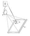
도 1은 본 발명의 실시예에 따른, 연설자 프레젠테이션이 대화형 디스플레이 시스템을 사용하여 수행되는 것의 개략 사시도.
도 2a 및 도 2b는, 각각, 본 발명의 실시예에 따른 대화형 디스플레이 시스템을 블록 형태로 나타낸 전기 회로도.
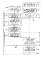
도 3a는 본 발명의 실시예에 따른 대화형 디스플레이 시스템의 동작을 나타낸 흐름도.
도 3b는 본 발명의 실시예의 대화형 디스플레이 시스템에 의해 디스플레이되는 영상에 포함되는 위치 확인 대상물을 나타낸 도면.
도 3c는 본 발명의 실시예에 따른 도 2a의 대화형 디스플레이 시스템의 동작을 나타낸 흐름도.
도 3d는 본 발명의 실시예에 따른 도 2b의 대화형 디스플레이 시스템의 동작을 나타낸 흐름도.
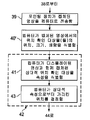
도 4a는 본 발명의 실시예에 따른, 하나 이상의 위치 확인 대상물을 포함하는 영상을 디스플레이하는 방법의 흐름도.
도 4b는 도 4a의 방법의 동작의 일례를 나타낸 흐름도.
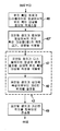
도 4c는 본 발명의 실시예에 따른, 디스플레이된 영상에서 위치 확인 대상물을 검출하는 방법의 흐름도.
도 5a 및 도 5b는 본 발명의 실시예에 따른, 포인팅 장치를 멀리 위치시킨 것과 가까이 위치시킨 것의 일례를 나타낸 도면.
도 6a는 감마 및 역감마 곡선의 그래프이고, 도 6b는 본 발명의 실시예에 따른, 위치 확인 대상물의 디스플레이에서 역감마 곡선을 적용하는 것을 나타낸 흐름도.
도 7은 디스플레이된 영상의 전체가 아닌 일부가 위치 확인 대상물에 포함되어 있는, 본 발명의 대안의 실시예에 따른 위치 확인 대상물의 디스플레이의 일례를 나타낸 도면.
도 8은 위치 확인 대상물의 규칙성이 붕괴되는, 본 발명의 대안의 실시예의 흐름도 및 대응하는 일례를 나타낸 도면.
도 9는 위치 확인 대상물의 콘트라스트가 배경 영상을 변조하는 것에 의해서도 감소되는, 본 발명의 대안의 실시예의 흐름도 및 대응하는 일례를 나타낸 도면.
도 10a 및 도 10b는 사람의 인지성(human perceptibility)을 감소시키기 위해 위치 확인 대상물이 컬러-가중되는, 본 발명의 대안의 실시예를 나타낸 흐름도.
도 11은 사람의 인지성을 추가로 감소시키기 위해 위치 확인 대상물의 에지가 블러링되는, 본 발명의 대안의 실시예를 나타낸 흐름도.
도 12는 다수의 위치 확인 대상물이 시간에 따라 순서화되는, 본 발명의 다른 실시예에 따른 대화형 디스플레이 시스템을 조작하는 방법을 나타낸 흐름도.
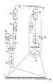
도 13a 내지 도 13e는 본 발명의 다른 실시예에 따른, 공칭 위치 확인 대상물, 포인팅 장치의 위치로 인한 그 위치 확인 대상물의 왜곡된 표현, 및 보상용 위치 확인 대상물을 나타낸 도면.1 is a schematic perspective view of a speaker presentation performed using an interactive display system, in accordance with an embodiment of the present invention.
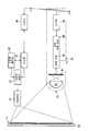
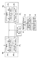
2A and 2B are each an electrical circuit diagram showing in block form an interactive display system according to an embodiment of the invention.
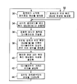
3A is a flow diagram illustrating operation of an interactive display system in accordance with an embodiment of the present invention.
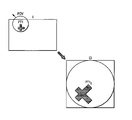
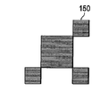
3B illustrates a positioning object included in an image displayed by the interactive display system of the embodiment of the present invention.
3C is a flow diagram illustrating operation of the interactive display system of FIG. 2A in accordance with an embodiment of the present invention.
FIG. 3D is a flow diagram illustrating operation of the interactive display system of FIG. 2B in accordance with an embodiment of the present invention. FIG.
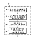
4A is a flow diagram of a method for displaying an image that includes one or more positioning objects, in accordance with an embodiment of the present invention.
4B is a flow diagram illustrating an example of the operation of the method of FIG. 4A.
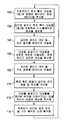
4C is a flowchart of a method for detecting a positioning object in a displayed image according to an embodiment of the present invention.
5A and 5B illustrate an example of positioning the pointing device closer to and farther away according to an embodiment of the invention.
6A is a graph of gamma and inverse gamma curves, and FIG. 6B is a flow chart illustrating application of an inverse gamma curve in the display of a positioning object, in accordance with an embodiment of the invention.
FIG. 7 illustrates an example of a display of a positioning object according to an alternative embodiment of the present invention, wherein part of the displayed image is included in the positioning object rather than all of it;
8 shows a flowchart and corresponding example of an alternative embodiment of the invention, in which the regularity of the positioning object is broken down;
9 shows a flowchart and corresponding example of an alternative embodiment of the invention, in which the contrast of the positioning object is also reduced by modulating the background image.
10A and 10B are flow diagrams illustrating an alternative embodiment of the present invention in which the location object is color-weighted to reduce human perceptibility.
11 is a flow diagram illustrating an alternative embodiment of the present invention in which the edge of the positioning object is blurred to further reduce the human perception.
12 is a flowchart illustrating a method of operating an interactive display system according to another embodiment of the present invention, in which a plurality of positioning objects are ordered over time.
13A-13E illustrate a nominal positioning object, a distorted representation of the positioning object due to the location of the pointing device, and a compensation positioning object, in accordance with another embodiment of the present invention.
본 발명이 청중이 볼 수 있는 디스플레이를 포함하는 컴퓨터화된 프레젠테이션 시스템으로 구현되어 있는 그의 하나 이상의 실시예와 관련하여 기술될 것인데, 그 이유는 본 발명이 이러한 시스템에 적용될 때 특히 유익할 것으로 생각되기 때문이다. 그렇지만, 본 발명이 게임 시스템, 사용자에 의한 컴퓨터 시스템에의 일반적인 입력 등과 같은 다른 응용과 관련하여 유용할 수 있다는 것도 생각된다. 그에 따라, 이하의 설명이 단지 일례로서 제공되고 청구된 본 발명의 진정한 범위를 제한하기 위한 것이 아님을 잘 알 것이다.The present invention will be described in connection with one or more embodiments thereof implemented as a computerized presentation system that includes an audience viewable display, which is believed to be particularly beneficial when the present invention is applied to such a system. Because. However, it is also contemplated that the present invention may be useful in connection with other applications, such as game systems, general input to a computer system by a user, and the like. Accordingly, it will be appreciated that the following description is provided merely as an example and is not intended to limit the true scope of the invention as claimed.
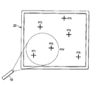
도 1은 본 발명의 실시예가 유용한 환경의 간략화된 일례를 나타낸 것이다. 도 1에 도시된 바와 같이, 연설자(SPKR)는 시각 교구(visual aid)를 사용하여 청중(A)에게 라이브 프레젠테이션을 제공하고 있다. 이 경우에, 시각 교구는 컴퓨터(22)에 의해 발생되는 컴퓨터 그래픽 및 텍스트의 형태로 되어 있고, 청중(A)에게 보이는 방식으로 방 크기의 그래픽 디스플레이(20) 상에 디스플레이된다. 기술 분야에 공지된 바와 같이, 이러한 프레젠테이션은 사업, 교육, 엔터테인먼트 및 기타 상황에서 흔하며, 특정의 청중 규모 및 시스템 요소가 아주 다양하다. 도 1의 간략화된 일례는 청중(A)이 프레젠테이션을 보고 있는 몇명 이상의 구성원을 포함하는 사업 환경을 예시한 것이고, 물론, 환경의 규모는 수백명의 청중 구성원이 앉아 있는 강당으로부터 청중(A)이 한명의 사람으로 이루어진 단일 책상 또는 테이블까지 다양할 수 있다.1 shows a simplified example of an environment in which embodiments of the present invention are useful. As shown in FIG. 1, the speaker SPKR is providing a live presentation to the audience A using a visual aid. In this case, the visual teaching aid is in the form of computer graphics and text generated by the
시각 교구를 청중(A)에게 제시하는 데 사용되는 디스플레이(20)의 유형도 역시 종종 프레젠테이션 환경의 규모에 따라 다양할 수 있다. 회의실부터 대규모 강당에 이르는 장소에서, 디스플레이(20)는 디스플레이 화면의 전방에 또는 그 후방에 있는 프로젝터를 포함하는 프로젝션 디스플레이일 수 있다. 그 환경에서, 컴퓨터(22)는 시각 교구 영상 데이터를 발생하여 프로젝터에 전달할 것이다. 소규모 환경에서, 디스플레이(20)는 컴퓨터(22) 내의 그래픽 어댑터에 의해 직접 구동되는 플라즈마 또는 액정(LCD) 유형 등의 외부 평판 디스플레이일 수 있다. 한명 또는 두명의 청중 구성원에 대한 프레젠테이션의 경우, 랩톱 또는 데스크톱 컴퓨터 형태의 컴퓨터(22)는 시각적 정보를 제시하기 위해 단순히 그 자신의 디스플레이(20)를 사용할 수 있다. 또한, 소규모 청중(A)에 대해, 핸드헬드 프로젝터(예컨대, "포켓 프로젝터" 또는 "피코 프로젝터")가 점점 더 흔해지고 있고, 이 경우에 디스플레이 화면은 벽 또는 화이트 보드가 될 수 있다.The type of
프레젠테이션과 관련하여, 그래픽 및 텍스트를 발생하여 제시하기 위해 컴퓨터 프레젠테이션 소프트웨어를 사용하는 것이 이제 보편화되어 있다. 이러한 프레젠테이션 소프트웨어의 잘 알려진 일례는 Microsoft Corporation으로부터 입수가능한 POWERPOINT 소프트웨어 프로그램이다. 도 1의 환경에서, 이러한 프레젠테이션 소프트웨어는 컴퓨터(22)에 의해 실행될 것이고, 이 일례에서 나타낸 바와 같이, 프레젠테이션에서의 각각의 슬라이드가 디스플레이(20) 상에 디스플레이된다. 물론, 특정의 시각적 정보가 컴퓨터(22)에서 실행되는 이전에 생성된 프레젠테이션일 필요는 없고, 그 대신에 컴퓨터(22)를 통해 액세스되는 웹 페이지; 아이콘, 프로그램 창, 및 동작 버튼을 포함하는 데스크톱 디스플레이; 컴퓨터(22)에 의해 판독되는 DVD 또는 기타 저장 장치로부터의 비디오 또는 영화 콘텐츠; 또는 심지어 [연설자(SPKR)가 포인팅 장치(10)를 사용하여 "그리거나" "쓸 수 있는"] "화이트 보드"처럼 비어 있는 화면일 수 있다. 본 명세서를 참조하면 본 발명의 실시예와 관련하여 유용한 다른 유형의 시각적 정보가 당업자에게 명백할 것이다.With regard to presentations, the use of computer presentation software to generate and present graphics and text is now commonplace. A well known example of such presentation software is the POWERPOINT software program available from Microsoft Corporation. In the environment of FIG. 1, this presentation software will be executed by the
도 1에 도시된 바와 같이, 청중(A)의 시청을 방해하지 않기 위해 또한 청중(A)을 더 잘 끌어들이기 위해 종종 연설자(SPKR)가 디스플레이(20)로부터 멀리 떨어져 서 있는 것이 유용하다. 본 발명의 실시예에 따르면, 연설자(SPKR)가, 컴퓨터(22) 및 디스플레이(20)로부터 멀리 떨어져서, 디스플레이(20)에 디스플레이되는 시각적 콘텐츠와 상호작용할 수 있다. 또한, 본 발명의 실시예에 따르면, 연설자(SKPR)가, 이러한 방식으로 시각적 콘텐츠와 상호작용하기 위해, 디스플레이(20)에 가까이 다가가서, 예를 들어, 가상 버튼 또는 링크에서 가상적으로 디스플레이(20)를 "누르거나" "터치"할 수 있다. 디스플레이(20)에 의해 디스플레이된 시각적 정보의 이러한 대화적 사용에 의해, 연설자(SPKR)가 컴퓨터(22)에 앉아 있거나 다른 방식으로 컴퓨터(22)에 "얽매여" 있을 필요 없이, 연설자(SPKR)는 특정의 청중(A)에 대해 유용할 것으로 생각되는 프레젠테이션을 즉석에서 만들 수 있고, 활성 콘텐츠(예컨대, 인터넷 링크, 활성 아이콘, 가상 버튼, 스트리밍 비디오 등)와 인터페이스할 수 있으며, 프레젠테이션의 고급 그래픽 및 제어를 할 수 있다.As shown in FIG. 1, it is often useful for the speaker SPKR to stand far from the
본 발명의 특정의 실시예와 관련하여 이하에서 더 상세히 기술할 것인 바와 같이, 연설자(SPKR)는 디스플레이(20)에서의 영상의 전부 또는 일부를 캡처할 수 있고 그 영상의 가리킨(또는 조준된) 목표 위치와 상호작용할 수 있는 포인팅 장치(10)에 의해 이러한 원격 상호작용을 수행한다. 이 일례에서, 포인팅 장치(10)는 디스플레이(20)의 이 가리킨 위치 및 연설자(SPKR)로부터의 다른 사용자 명령을 수신기(24)에, 따라서 컴퓨터(22)에 무선으로 전달한다. 이러한 방식으로, 본 발명의 실시예에 따르면, 디스플레이된 영상과의 원격 상호작용이 수행된다.As will be described in more detail below with respect to certain embodiments of the present invention, the speaker SPKR can capture all or a portion of the image on the
대화형 디스플레이 시스템의 일반 구조 및 동작General structure and operation of the interactive display system
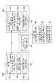
이제 도 2a를 참조하여, 도 1에 도시된 것과 같은 환경에서 유용한 본 발명의 실시예에 따른 대화형 디스플레이 시스템의 구조의 일반화된 일례에 대해 이제부터 기술할 것이다. 도 2a에 도시된 바와 같이, 이 대화형 디스플레이 시스템은 포인팅 장치(10), 프로젝터(21), 및 디스플레이 화면(20)을 포함하고 있다. 본 발명의 이 실시예에서, 컴퓨터(22)는 프로젝터(21)에 의해 디스플레이 화면(20)에 디스플레이될 "페이로드" 영상 - 이러한 페이로드 영상은 청중이 보도록 의도되어 있는 것임 - 을 발생하는 해당 기능을 포함하고 있다. 본 발명의 실시예에 따라, 이들 페이로드 영상의 콘텐츠는 포인팅 장치(10)를 통해 사람 사용자에 의해 대화적으로 제어된다. 그렇게 하기 위해, 컴퓨터(22)는 포인팅 장치(10)가 가리키고 있는 디스플레이 화면(20)의 위치를 결정하는 위치 확인 회로(25)와 협력한다. 이하의 설명으로부터 명백하게 될 것인 바와 같이, 이 위치 결정은 포인팅 장치(10)가 디스플레이 화면(20)에 디스플레이되는 하나 이상의 위치 확인 대상물을 검출하는 것에 기초하고 있다.Referring now to FIG. 2A, a generalized example of the structure of an interactive display system according to an embodiment of the present invention useful in an environment such as that shown in FIG. 1 will now be described. As shown in FIG. 2A, this interactive display system includes a
컴퓨터의 페이로드 영상 발생 기능에서, 컴퓨터(22)는, 예를 들어, 메모리에 저장되어 있는 이전에 발생된 프레젠테이션 파일의 형태로 되어 있는 또는 컴퓨터(22)가 네트워크 또는 인터넷을 통해 검색할 수 있는 활성 콘텐츠의 형태로 되어 있는 디스플레이될 시각적 정보(즉, 시각적 "페이로드" 영상)를 발생하거나 그에 액세스할 수 있다. 또한 이하에서 더욱 상세히 기술될 것인 바와 같이, 컴퓨터(22)로부터의 이러한 사람이 볼 수 있는 페이로드 영상 프레임 데이터가 대상물 발생기 기능부(23)에 의해 발생되는 위치 확인 대상물 영상 콘텐츠 - 그래픽 디스플레이(20)에 디스플레이될 때, 포인팅 장치(10)에 의해 캡처되고, 포인팅 장치(10)가 가리키는 위치를 추론하기 위해 위치 확인 회로(25)에 의해 사용될 수 있음 - 와 결합될 것이다. 그래픽 어댑터(27)는 페이로드 영상 데이터와 위치 확인 대상물 영상 콘텐츠의 결합을 포함한 영상 데이터 프레임 시퀀스를 적당한 디스플레이 형식으로 프로젝터(21)에 제시하기에 적당한 해당 기능을 포함한다. 이 프로젝션 일례에서, 프로젝터(21)는 차례로 대응하는 영상(I)을 디스플레이 화면(20)에 투사한다.In the payload image generation function of the computer, the
컴퓨터(22), 위치 확인 회로(25), 대상물 발생기 회로(23), 및 그래픽 어댑터(27)의 특정의 구조가 아주 다양할 수 있다. 예를 들어, 적절한 처리 회로(CPU 또는 마이크로프로세서) 및 메모리를 포함하는 단일 개인용 컴퓨터 또는 워크스테이션(데스크톱, 랩톱, 또는 기타 적당한 형태로 되어 있음)이 페이로드 영상을 발생하는 기능, 위치 확인 대상물을 발생하는 기능, 그래픽 어댑터(27) 이전에서 또는 그래픽 어댑터(27)를 통해 이 둘을 결합하는 기능은 물론, 포인팅 장치(10)로부터 데이터를 수신하고 처리하여 디스플레이된 영상의 가리킨 위치를 결정하는 기능을 수행하도록 구성되고 프로그램될 수 있는 것이 생각되고 있다. 다른 대안으로서, 컴퓨터(22)가 수정 없이 동작하는 종래의 컴퓨터로서 실현될 수 있도록 컴퓨터(22) 외부에 있는 별도의 기능 시스템이 대상물 발생기(23), 수신기(24), 및 위치 확인 회로(25)의 기능들 중 하나 이상의 기능을 수행할 수 있는 것이 생각되고 있으며, 이 경우에, 그래픽 어댑터(27)는 그 자체가 외부 기능을 구성할 수 있거나[또는 컴퓨터(22)의 외부에 있는 대상물 발생기(23), 수신기(24), 및 위치 확인 회로(25)의 다른 기능들 중 하나 이상의 기능과 결합될 수 있음], 다른 대안으로서, 대상물 발생기(23)로부터의 출력이 제시되는 컴퓨터(22) 내에서 실현될 수 있다. 이들 기능의 다른 다양한 대안의 구현도 역시 생각되고 있다. 어느 경우든지, 컴퓨터(22), 위치 확인 회로(25), 대상물 발생기(23), 그리고 그래픽 디스플레이(20)에 디스플레이되는 영상 및 위치 확인 대상물의 발생에 관여된 다른 기능이, 그의 처리 회로에 의해 실행될 때, 본 명세서에 기술된 본 발명의 실시예의 다양한 기능 및 동작을 수행하게 될 컴퓨터 프로그램 명령어를 저장하는 컴퓨터 판독가능 매체 형태로 되어 있는 적절한 프로그램 메모리를 포함하는 것이 생각되고 있다. 본 명세서를 참조하면 당업자가 과도한 실험 없이 본 발명의 이들 실시예를 구현하기 위해 적절한 컴퓨터 하드웨어 및 대응하는 컴퓨터 프로그램을 즉각 구성할 수 있는 것이 생각되고 있다.The specific structures of the
이 일례에서, 포인팅 장치(10)는 광학 시스템(12) 및 이미지 센서(14)로 이루어진 카메라 기능을 포함하고 있다. 포인팅 장치(10)가 디스플레이(20)를 조준하는 경우, 이미지 센서(14)가, 포인팅 장치(10)와 디스플레이(20) 사이의 거리, 광학 시스템(12) 내의 렌즈의 초점 거리 등에 따라, 디스플레이(20)에서의 영상(I)의 전부 또는 일부에 대응하는 캡처된 영상에 노출된다. 영상 캡처 기능부(16)는 사용자에 의해 선택된 특정의 시점에서 캡처된 또는 일련의 샘플 시간(sample time) 각각에서 캡처된 영상의 디지털 표현을 획득하여 저장하는 기술 분야에 공지된 적절한 회로를 포함하고 있다. 이하에서 기술될 것인 바와 같이 그리고 당업자에게는 명백할 것인 바와 같이, 포인팅 장치(10)는 또한 종래의 푸시-버튼 또는 기타 스위치인 작동기(15) - 이를 통해 포인팅 장치(10)의 사용자는 영상 캡처를 작동시키기 위해 또는 다른 기능을 위해 마우스 버튼과 비슷한 사용자 입력을 제공할 수 있음 - 를 포함하고 있다. 이 일례에서, 디스플레이된 콘텐츠와의 사용자 상호작용을 지원하거나 향상시키기 위해 하나 이상의 관성 센서(17)가 또한 포인팅 장치(10) 내에 포함되어 있고, 이러한 관성 센서의 일례는 가속도계, 자기 센서(즉, 지자계에 대한 배향을 감지하기 위한 것임), 자이로스코프, 및 기타 관성 센서를 포함한다.In this example, the
도 2a의 이 일례에서, 포인팅 장치(10)는 영상 캡처 기능부(16)에 의해 획득되는 캡처된 영상에 대응하는 신호를 위치 확인 회로(25)로 전달하는 동작을 한다. 이 통신 기능은 포인팅 장치(10) 내의 무선 송신기(18) 및 그의 내부 안테나(A) - 이를 통해 (블루투스 또는 적절한 IEEE 802.11 표준 등의 종래의 표준에 따라) 무선 주파수 신호가 전송됨 - 에 의해 수행된다. 송신기(18)는, 적용가능한 무선 프로토콜을 통해, 캡처된 영상 데이터와 기타 사용자 입력 및 제어 신호를 인코딩, 변조 및 전송하는 종래의 구성 및 동작을 갖는 것으로 생각된다. 이 일례에서, 수신기(24)는 포인팅 장치(10)의 안테나(A)를 통해 포인팅 장치(10)로부터 전송된 신호를 수신할 수 있고, 수신된 신호를 복조, 디코딩, 필터링 및 다른 방식으로 처리하여 위치 확인 회로(25)에서 처리하기에 적당한 기저대역 형태로 만들 수 있다.In this example of FIG. 2A, the
이제부터 도 3a를 참조하여, 본 발명의 실시예에 따른 대화형 디스플레이 시스템의 동작에 대해 전반적으로 기술할 것이다. 프로세스(30)에서, 컴퓨터(22)는 디스플레이(20)에서 디스플레이될 시각적 페이로드 영상 데이터를 발생한다. 이 시각적 페이로드 영상 데이터는 도 1의 환경에 있는 청중(A)이 보도록 의도되어 있는 사람이 인지할 수 있는 콘텐츠에 대응하고, 이러한 콘텐츠는 프레젠테이션의 시각적 구성요소를 구성하는 시각 교구(POWERPOINT 슬라이드, 웹 페이지 등)에 대응한다. 이 시각적 페이로드 영상 데이터와 함께, 프로세스(32)에서, 대상물 발생기 기능부(23)는 시각적 페이로드 영상 데이터와 함께 역시 디스플레이(20) 상에 디스플레이될 위치 확인 대상물 영상을 발생한다. 본 발명의 실시예에 따른 이 위치 확인 대상물 영상의 특성에 대해 이하에서 더 상세히 기술할 것이다. 본 발명의 실시예에서, 프로세스(32)에서 발생된 위치 확인 대상물 영상이 청중(A)에 의해 직접 인지가능할 필요는 없고, 이 시스템의 동작을 위해 포인팅 장치(10)에 의해 인지가능하기만 하면 된다. 프로세스(34)에서, 그래픽 어댑터(27)는 시각적 페이로드 영상 데이터와 위치 확인 대상물 영상 데이터를 결합하여 디스플레이(20)에서 디스플레이하기에 적당한 형태로(예를 들어, 통상적인 의미에서 그래픽 또는 비디오 데이터의 하나 이상의 "프레임"의 형태로) 만든다. 다른 대안으로서, 컴퓨터(22)는 대상물 발생기 기능부(23)로부터 위치 확인 대상물을 수신하고 그 위치 확인 대상물을 페이로드 영상 데이터와 결합시킨 후에 결합된 결과를 그래픽 어댑터(27)로 전달할 수 있고, 이 경우에, 컴퓨터(22) 및 대상물 발생기 기능부(23) 중 하나 또는 둘 다가 그래픽 어댑터 회로를 포함할 수 있고, 이들 경우 중 어느 하나 또는 다른 대안으로서 후속 그래픽 어댑터가 그래픽 출력을 프로젝터(21)에 제시하는 그래픽 어댑터로서 역할한다. 그렇지만, 결합된 경우, 프로세스(36)에서, 그 결합된 프레임이 종래의 방식으로 디스플레이(20)에서 출력되기 위해 프로젝터(21)에 전달된다. 다른 대안으로서, 다른 유형의 디스플레이 시스템(LCD, LED 및 다른 비프로젝션 디스플레이 등)의 경우, 프로젝션(21)가 이용되지 않을 것이고, 오히려 그래픽 디스플레이(20) 자체가 결합된 페이로드 영상 및 위치 확인 대상물을 수신하고 디스플레이하는 적절한 기능을 포함할 것이다.Referring now to FIG. 3A, the overall operation of an interactive display system according to an embodiment of the present invention will be described. In
도 3b는 프로세스(36) 이후에 디스플레이(20) 상에 디스플레이되는 영상(I)의 일반화된 일례를 나타낸 것이다. 이 도 3b에 도시된 바와 같이, 영상(I)은 디스플레이(20)에 디스플레이된 영상(I)의 좌측 상부 사분면에 있는 기본적인 위치 확인 대상물(PT1)을 포함한다. 위치 확인 대상물(PT1)이 어떤 대칭성을 포함하는 것이 유용하고, 따라서 디스플레이(20)의 축에 대한 포인팅 장치(10)의 회전이 위치 확인 회로(25)에 의한 캡처된 영상의 분석으로부터 식별될 수 있다. 포인팅 장치(10) 내에 구현되는 가속도계 등의 보조 움직임 센서가 이 회전 배향 결정에 도움을 주어, 위치 확인이 보다 빠르게 수행될 수 있게 해주는 것이 생각되고 있다.3B shows a generalized example of the image I displayed on the
프로세스(38)에서 포인팅 장치(10)가 디스플레이(20)에 디스플레이되고 있는 영상의 적어도 일부를 캡처하는 것에 의해, 대화형 디스플레이 동작이 계속된다. 앞서 언급한 바와 같이, 포인팅 장치(10)는 사용자 명령 시에[예를 들어, 작동기(15)를 통해] 이 영상을 캡처할 수 있고, 다른 대안으로서, 포인팅 장치(10)는 샘플링된 영상 시퀀스의 형태로 영상을 주기적으로 캡처할 수 있다. 어느 한 경우에, 시스템의 대화형 동작을 달성하기 위해, 포인팅 장치(10)에 의해 캡처된 영상 또는 영상들은 디스플레이된 영상 내의 하나 이상의 위치 확인 대상물을 사람이 인지할 수 있는 시각적 페이로드 영상과 함께 포함할 것이다. 도 3b는 포인팅 장치(10)가, 시야(field of view, FOV)로 나타낸 바와 같이, 디스플레이된 영상(I)을 가리키고 있는 경우에 대한 캡처된 영상(CI)의 일례를 나타낸 것이다. 도 3b에 나타낸 바와 같이, 캡처된 영상(CI)이 획득되는 시야(FOV)는 디스플레이된 영상(I)의 일부분만을 포함하고, 그에 부가하여 시야(FOV)가 디스플레이된 영상(I)의 배향으로부터 (예컨대, 반시계 방향으로 45°) 회전되어 있다. 이 일례에서, 캡처된 영상(CI)은 캡처된 위치 확인 대상물(PT1C)을 포함한다.The interactive display operation continues by the
포인팅 장치(10)가 적어도 하나의 위치 확인 대상물을 포함하는 적어도 하나의 영상을 획득할 시에, 대화형 디스플레이 시스템 내의 위치 확인 회로는, 프로세스(40)에서, 캡처된 영상 내에 포함된 위치 확인 대상물 영상의 속성을 확인한다. 이 속성은 포인팅 장치(10)가 보는, 캡처된 영상에서의 위치 확인 대상물의 위치를 포함하고, 또한 그 캡처된 영상에서의 위치 확인 대상물의 크기[이 크기는 포인팅 장치(10)와 디스플레이(20) 간의 거리를 나타냄], 캡처된 영상에서의 위치 확인 대상물의 배향[디스플레이에 대한 포인팅 장치(10)의 배향을 나타냄], 캡처된 영상에서의 위치 확인 대상물의 형상[디스플레이(20)에 수직인 축을 벗어난 포인팅 장치(10)의 위치를 나타낼 수 있음], 기타 등등의 속성도 포함할 수 있다. 도 3b의 기본적인 일례를 참조하면, 캡처된 위치 확인 대상물(PT1C)의 위치가 (예컨대, 어떤 좌표를 통해) 캡처된 영상(CI)의 좌측 하부 섹터에 있는 것으로 식별될 수 있다. 캡처 시에 포인팅 장치(10)가 디스플레이(20)에 얼마나 가까이 있는지의 표시를 제공하기 위해 캡처된 위치 확인 대상물(PT1C)의 상대 크기가 식별될 수 있고, 그에 부가하여, 캡처된 그의 형상에서의 대칭성으로부터 캡처된 위치 확인 대상물(PT1C)의 배향이 식별될 수 있다.When the
이들 식별된 속성에 기초하여, 도 2a의 시스템 내의 위치 확인 회로(25)는, 프로세스(42)에서, 영상 캡처 시에 포인팅 장치(10)가 가리키는 디스플레이된 영상(I)의 위치를 결정한다. 일반적으로, 프로세스(42)의 이 결정은 캡처된 영상(CI)을 대응하는 때의 영상(I)을 형성하는 비디오 데이터와 비교함으로써 달성된다. 이 비교는 비디오 데이터의 직접 비교[즉, 시야(FOV)를 영상(I) 내의 정확한 곳에 위치시키기 위해 캡처된 영상(CI)의 비트맵을 디스플레이된 영상(I)의 비트맵과 비교하는 것]로서 수행될 수 있다. 다른 대안으로서, 크기, 배향, 형상, 기타 등등의 식별된 속성이 또한 디스플레이된 위치 확인 대상물의 유사한 속성과 비교될 수 있고, 이로부터 디스플레이(20)에 대한 포인팅 장치(10)의 상대 위치가 계산될 수 있다. 본 명세서를 참조하면 당업자가, 캡처된 영상(CI) 및 디스플레이된 영상(I)이 주어진 경우, 과도한 실험 없이, 가리킨 위치를 결정하는 적절한 알고리즘 및 방법을 즉각 개발할 수 있는 것이 생각되고 있다.Based on these identified attributes, the
어쨋든, 포인팅 장치(10)가 가리키는 디스플레이(20)의 위치를 결정하면, 영상 캡처 시에, 컴퓨터(22)는 이어서 그래픽 사용자 인터페이스 방식으로 포인팅 장치(10)를 통해 사용자에 의해 주어진 명령을 디코딩할 수 있다. 기술 분야의 기초로서, 그래픽 사용자 인터페이스 명령은 "선택", 클릭 앤 드래그, 더블-클릭, 우측 클릭 등과 같은 기능은 물론, 디스플레이된 콘텐츠의 줌인 또는 줌아웃, 페이지 넘기기 등을 비롯한 다른 명령도 포함한다. 이러한 명령의 다른 일례는 포인팅 장치(10)를 사용하여, 디스플레이된 콘텐츠 상에(예를 들어, 그 콘텐츠를 하이라이트하거나 그에 주석을 달기 위해) 또는 비어 있는 "화이트 보드" 디스플레이 상에, 손으로 영상 그리기 또는 손으로 글씨 쓰기를 하는 것을 포함한다. 그래픽 사용자 인터페이스와 관련하여, 이들 명령은 취해질 실제 동작을 포함할 뿐만 아니라, 디스플레이된 영상 내의 현재 가리킨 위치에도 의존한다. 이러한 방식으로 사용자 명령을 디코딩할 시에, 대화형 디스플레이 시스템은, 예를 들어, 프로세스(30)에서, 수신된 사용자 명령에 응답하여 디스플레이될 새로운 시각적 페이로드 영상 콘텐츠를 발생함으로써 이 프로세스를 반복한다. 선택적으로, 그 다음 프로세스(32)에서 역시 디코딩된 명령에 응답하여 위치 확인 대상물이 발생되고 디스플레이된 영상 내에 결합될 수 있고, 예를 들어, [그 다음 위치 확인 대상물이 포인팅 장치(10)에서 보이는 곳에 있도록 하기 위해] 그 다음 위치 확인 대상물의 위치가 디스플레이의 현재 가리킨 위치에 의존할 수 있다. 이어서, 이 프로세스가 반복된다.In any case, upon determining the position of the
본 발명의 실시예의 대화형 디스플레이 시스템에서의 위치 확인 회로(25)의 특정의 위치가 시스템마다 다를 수 있는 것이 생각되고 있다. 일반적으로, 어느 하드웨어 서브시스템(즉, 디스플레이를 구동하는 컴퓨터, 포인팅 장치, 비디오 데이터 경로에 있는 별도의 서브시스템, 또는 이들의 어떤 조합)이 디스플레이(20)의 가리킨 위치의 결정을 수행하는지가 특별히 중요하지는 않다. 도 2a에 도시된 일례에서, 앞서 기술한 바와 같이, 디스플레이된 영상(I)를 발생하는 기능 및 포인팅 장치(10)가 가리키고 있는 디스플레이된 영상(I)의 위치를 결정하는 기능(및 그와 연관된 명령을 디코딩하는 기능)을 시스템의 동일한 요소 내에 겸비하고 있는 시스템에, 컴퓨터(22) 및 대상물 발생기 기능부(23)와 함께 위치 확인 회로(25)가 설치되어 있다.It is contemplated that the specific position of the
이와 관련하여, 도 3c는 도 3a와 관련하여 앞서 기술한 전체 프로세스의 일부분을 나타낸 것이지만, 보다 구체적으로는 도 2a의 시스템에 적용된다. 이 경우에, 도 3c의 대화형 디스플레이 동작은, 도 3a와 관련하여 앞서 기술한 바와 같이, 포인팅 장치(10)가 디스플레이(20)에 디스플레이된 영상(I)의 적어도 일부를 캡처하는 프로세스(38)을 통해 진행된다. 프로세스(39)(도 3c)에서, 포인팅 장치(10)는 캡처된 영상(CI)에 대응하고 하나 이상의 위치 확인 대상물을 포함하는 신호를 송신기(18) 및 안테나(A)를 통해 위치 확인 회로(25)로 전송한다. 수신기(24)에서 그 캡처된 영상 데이터를 수신할 시에, 위치 확인 회로(25)는 캡처된 영상(CI) 데이터 내에서 하나 이상의 위치 확인 대상물을 식별하는 프로세스(40')를 실행한다. 그 위치 확인 대상물의 위치를 식별하는 것에 부가하여, 위치 확인 회로(25)는 또한 크기, 배향, 기타 등등의 위치 확인 대상물의 다른 속성도 식별할 수 있다.In this regard, FIG. 3C illustrates a portion of the overall process described above with respect to FIG. 3A, but more specifically applies to the system of FIG. 2A. In this case, the interactive display operation of FIG. 3C is a
가리킨 위치를 결정하는 것[도 3a의 프로세스(42)]이, 도 2a의 시스템에서, 캡처된 영상(CI) 내의 위치 확인 대상물 영상 콘텐츠의 속성이 디스플레이된 영상(I) 내의 대응하는 위치 확인 대상물 영상 콘텐츠와 비교되는 프로세스(41)를 통해, 위치 확인 회로(25)에 의해 수행된다. 이상에서 기술한 바와 같이, 프로세스(41)는 비디오 영상 콘텐츠의 직접 비교에 의해, 또는 다른 대안으로서, 특정의 구현에 따라 특정의 속성에 기초한 계산(영상 필드에서의 x-y 위치의 비교 등)을 통해 수행될 수 있다. 프로세스(41)에서 식별된 디스플레이(20)에 대한 포인팅 장치(10)의 상대 위치는 프로세스(43)에서 디스플레이(20)의 가리킨 위치를 결정하기 위해 컴퓨터(22)에 의해 사용된다. 대화형 디스플레이 프로세스는 이어서, 앞서 기술한 바와 같이, 컴퓨터(22)가 현재 사용자 명령을 디코딩하고 실행하는 프로세스(44)로 계속된다.Determining the location pointed to (
도 2b는 본 발명의 실시예에 따른 대화형 디스플레이 시스템의 대안의 일반화된 구성을 나타낸 것이다. 이 시스템은 이전과 같이 프로젝터(21) 및 디스플레이(20)를 포함하고, 프로젝터(21)는 앞서 기술한 바와 같이 컴퓨터(22)에 의해 발생된 페이로드 영상 콘텐츠 및 위치 확인 대상물 영상 콘텐츠를 투사한다. 이 일례에서, 포인팅 장치(10')는 현재 가리키고 있는 디스플레이(20)의 위치를 결정하는 데 수반되는 계산의 일부 또는 전부를 수행한다. 그에 따라, 카메라[렌즈(12), 이미지 센서(14) 및 영상 캡처(16)]에 부가하여, 위치 확인 장치(10')는 위치 확인 회로(25')를 무선 송신기(18)와 함께 포함하고 있다. 이와 달리, 컴퓨터(22)는 이전과 같이 수신기(24)에 결합되어 있다.2B illustrates an alternative generalized configuration of an interactive display system according to an embodiment of the present invention. The system includes the
일반적으로, 위치 확인 회로(25')는 이어서 그의 이미지 센서(14)에서 획득되는 캡처된 영상(I) 내에 포함된 위치 확인 대상물 영상 콘텐츠를 그의 메모리에 저장되어 있는 위치 확인 대상물 영상 정보와 비교함으로써 가리키고 있는 디스플레이(20)의 위치를 결정한다. 예를 들어, 위치 확인 회로(25')는, 이전에, 디스플레이(20)에 디스플레이될 위치 확인 대상물의 공칭 형상 및 크기에 대응하는 영상 데이터를 저장하고 있을 수 있으며, 따라서 캡처된 영상을 그 위치 확인 대상물 영상과 비교할 수 있다. 다른 대안으로서, 송신기(18) 및 수신기(24) 각각은 서로와의 무선 통신을 수신하기도 하고 전송하기도 할 수 있는 송수신기로서 구현될 수 있고, 이 경우에, 디스플레이(20)에 디스플레이되는 위치 확인 대상물의 크기, 형상 및 위치에 대응하는 데이터가 비교를 위해 포인팅 장치(10')로 전송될 수 있다. 어느 한 경우에, 도 2b의 시스템에서 포인팅 장치(10')에 있는 위치 확인 회로(25')의 적어도 일부분이 분산되어 있는 것에 의해 전체 동작이 얼마간 다르며, 이에 대해서는 구체적으로는 도 2b의 시스템에 적용되는 도 3d에 도시된 전체 프로세스 흐름의 일부분과 관련하여 이제부터 기술할 것이다.In general, the
위치 확인 회로(25')에 사전 저장되어 있든 무선 전송에 의해 수신되든 간에, 프로세스(46)에서, 포인팅 장치(10')는 대상물 발생기(23)에 의해 발생되고 디스플레이된 영상(I)에 포함되는 위치 확인 대상물 영상 콘텐츠에 대응하는 데이터에 액세스한다. 이 데이터는 위치 확인 대상물 영상 콘텐츠 데이터 자체[예컨대, 도 3b의 위치 확인 대상물(PT1)]일 수 있거나, 다른 대안으로서, 어떤 유형의 표현 데이터(예컨대, x-y 위치, 배향 등) - 이로부터 위치 확인 회로(25')는 위치 확인 대상물 영상 콘텐츠의 위치 및 기타 속성을 결정할 수 있음 - 일 수 있다. 프로세스(40")에서, 포인팅 장치(10) 내의 위치 확인 회로(25')는 캡처된 영상(CI) 내에서 하나 이상의 위치 확인 대상물[예컨대, 위치 확인 대상물(PT1C)]을 식별하고, 원하는 바에 따라, 크기, 배향 등과 같은 위치 확인 대상물 속성을 결정한다.Whether stored pre-stored in the positioning circuit 25 'or received by wireless transmission, in process 46, the pointing device 10' is included in the image I generated and displayed by the
위치 확인 회로(25')가 포인팅 장치(10') 내에 제공되어 있는 도 2b의 시스템에서, 위치 확인 회로(25')는 캡처된 영상(CI) 내의 위치 확인 대상물과 [프로세스(46)에서 컴퓨터(22)로부터 전달되는] 디스플레이된 영상(I) 내의 위치 확인 대상물 간의 관계를 식별하기 위해 프로세스(47)를 실행한다. 이 동작은 본질적으로 도 3c의 프로세스(41)에 대응하지만, 컴퓨터(22)(도 2a)에서보다는 포인팅 장치(10')에서 수행된다. 프로세스(48)에서, 포인팅 장치(10')의 영상 캡처 및 위치 확인 회로(16')는, 프로세스(47)에서 도출된 상대적 속성에 기초하여, 포인팅 장치(10') 자체가 영상 캡처 시에 가리키고 있었던 디스플레이(20)의 위치를 결정한다. 포인팅 장치(10')가 가리킨 디스플레이(20)의 위치를 결정하면, 프로세스(49)에서, 포인팅 장치(10')는 이어서 그 가리킨 위치를 식별해주는 데이터를 임의의 명령 또는 기타 사용자 입력[예컨대, 작동기(15)를 통한 입력]과 함께, 송신기(18) 및 수신기(24)에 의해 설정된 무선 링크를 통해, 컴퓨터(22)로 전송한다. 컴퓨터(22)는 이어서, 이상에서 기술한 바와 같이, 프로세스(44)로부터의 원하는 대화형 방식으로 그의 동작 및 영상(I)의 디스플레이에서 이들 명령에 응답할 수 있다.In the system of FIG. 2B in which a positioning circuit 25 'is provided within the pointing device 10', the positioning circuit 25 'is a computer in process 46 and a positioning object in the captured image CI.
게다가, 역시 도 2b에 의해 암시되는 대안에서, 포인팅 장치(10, 10')가 가리키고 있는 디스플레이(20)의 위치를 계산하고 결정하는 위치 확인 회로(25, 25')가 시스템에 걸쳐 분산되어 있을 수 있고, 포인팅 장치(10, 10') 둘 다에 그리고 컴퓨터(22)에 있는 일부분 각각은 위치 확인 기능의 어떤 부분을 수행한다. 예를 들어, 포인팅 장치(10')에 있는 위치 확인 회로(25')는 그의 캡처된 영상(CI) 내에 포함된 위치 확인 대상물 영상 콘텐츠의 속성(예컨대, x-y 위치, 대상물 크기, 배향 등)을 계산하고, 이어서 그 정보를 컴퓨터(22) 근방에 설치된 위치 확인 회로(25)에 전달할 수 있으며, 이것으로 디스플레이(20)의 가리킨 위치의 결정이 완료된다. 본 명세서를 참조하면, 과도한 실험 없이, 당업자에 의해 특정의 구현을 위해 다양한 시스템 구성요소 간의 위치 확인 기능 및 계산 자원의 특정의 분산이 설계될 수 있는 것이 생각되고 있다.In addition, in the alternative also implied by FIG. 2B,
이 일반화된 설명에 주어진 경우, 위치 확인 대상물 정보가 발생되고 디스플레이(20)에 디스플레이되는 방식에 관한 본 발명의 다양한 실시예, 및 본 발명의 그 실시예를 통해 달성되는 이점들 중 일부에 대해 이제부터 기술할 것이다.Given this generalized description, now with respect to various embodiments of the present invention regarding the manner in which the positioning object information is generated and displayed on the
사람이 인지할 수 없는 위치 확인 대상물Location object that human cannot recognize
발명의 배경 기술에서 앞서 논의한 바와 같이, 원격 포인팅 장치의 위치 확인에 대한 많은 종래의 방식은 포인팅 장치가 가리키는 디스플레이의 위치를 인식하기 위해 디스플레이된 영상에서의 사람이 인지할 수 있는 콘텐츠를 사용하는 것을 포함한다. 어떤 경우에, 눈에 보이는 커서가 위치 확인 대상물을 구성하고, 가리킨 위치는 캡처된 영상에서의 커서의 위치 및 속성을 디스플레이되는 커서의 위치 및 속성과 비교함으로써 결정된다. 다른 경우에, 영상의 가시 콘텐츠, 또는 실제로 디스플레이된 영상 자체의 코너가 위치 확인 프로세스에 관여되어 있다. 그렇지만, 디스플레이된 영상에서의 다른 방식으로 인지가능한 영상 또는 커서의 사용은 청중의 주의를 산만하게 할 수 있고, 디스플레이 시스템이 발표자가 시각적 콘텐츠를 그리거나 쓰는 "화이트-보드"로서 사용되는 경우에 특히 그렇다. 이들 종래의 가시 대상물 시스템(visible-target system)은 엄격히 말해 "화이트 보드" 응용에서 제대로 기능할 수 없는데, 그 이유는 위치 확인 기능에서 사용될 수 있는 시각적 콘텐츠가 디스플레이되지 않기 때문이다. 그에 부가하여, 본 발명에 따르면, 이들 종래의 방식이 디스플레이 화면으로부터의 거리의 측면에서 포인팅 장치의 사용가능 범위를 제한하는 것이 관찰되었고, 포인팅 장치가 디스플레이에 너무 가까이 있는 경우, 포인팅 장치에 의해 캡처되는 대상물이 너무 커서 분간할 수 없을지 모르거나, 포인팅 장치가 디스플레이로부터 너무 멀리 떨어져 있는 경우 너무 작아서 분간할 수 없을지 모른다.As discussed above in the background of the invention, many conventional approaches to locating a remote pointing device involve using human perceptible content in the displayed image to recognize the location of the display pointed to by the pointing device. Include. In some cases, a visible cursor constitutes a positioning object, and the pointed position is determined by comparing the position and attributes of the cursor in the captured image with the position and attributes of the displayed cursor. In other cases, the visible content of the image, or the corner of the image itself that is actually displayed, is involved in the positioning process. However, the use of other perceivable images or cursors in the displayed image can distract the audience's attention, especially when the display system is used as a "white-board" for the presenter to draw or write visual content. Yes. These conventional visible-target systems are not strictly able to function properly in "white board" applications, since no visual content that can be used in the positioning function is displayed. In addition, according to the present invention, it has been observed that these conventional approaches limit the usable range of the pointing device in terms of distance from the display screen, and if the pointing device is too close to the display, it is captured by the pointing device. The object may be too large to distinguish, or may be too small to distinguish if the pointing device is too far from the display.
본 발명의 실시예에 따르면, 포인팅 장치(10)의 위치 확인[즉, 포인팅 장치(10)가 가리키는 디스플레이(20)의 위치를 결정하는 것]이 청중이 직접 인지할 수 없는 위치 확인 대상물을 사용하여 수행된다. 그에 부가하여, 본 발명의 실시예는, 디스플레이에 대한 하드웨어 수정 - 부가의 프로젝터, 특수 프레임 레이트 오버레이, 위치 확인 대상물에 대해 적외선 등의 비가시 광을 사용하는 부가의 프로젝션 서브시스템, 기타 등등 - 을 필요로 하지 않고, 사람이 인지할 수 없지만 여전히 디스플레이 시스템의 공칭 프레임 레이트로 동작하는 대상물을 사용하여 이러한 위치 확인을 수행한다.According to an embodiment of the present invention, positioning of the pointing device 10 (ie, determining the position of the
도 4a 내지 도 4c는 본 발명의 실시예에 따른 대화형 디스플레이 시스템에서의 위치 확인 대상물의 발생, 디스플레이 및 검출의 일례를 나타낸 것이다. 이와 관련하여 본 명세서에 기술된 동작이 대화형 디스플레이 시스템의 적절한 구성요소에 의해 - 예를 들어, 도 2a 및 도 2b와 관련하여 전술한 시스템에서의 대상물 발생기 기능부(23) 및 그래픽 어댑터(27)를 통해 - 수행되고 실행되는 것이 생각되고 있다. 또한, 대략 60 Hz 등의 다양한 유형의 최신의 종래 디스플레이에 의해 현재 사용되는 공칭 레이트로부터 프레임 레이트의 증가를 필요로 하지 않고, 이 발생 및 디스플레이 프로세스가 수행될 수 있는 것이 생각되고 있다. 본 명세서를 참조하여 당업자가 과도한 실험 없이 본 명세서에 기술된 동작을 수행하기 위해 대상물 발생기 기능부(23)를 비롯한 이들 다양한 기능을 용이하게 구성하고 프로그램할 수 있는 것이 생각되고 있다.4A-4C illustrate an example of generation, display and detection of a positioning object in an interactive display system according to an embodiment of the present invention. In this regard, the operations described herein may be performed by appropriate components of the interactive display system—for example, the
시각적 페이로드 영상 콘텐츠 및 사람이 인지할 수 없는 위치 확인 대상물을 비롯한 디스플레이된 영상을 발생하고 디스플레이하는 것에 대해 기술하는 도 4a의 흐름도에 도시된 바와 같이, 프로세스(30)에서, 컴퓨터(22)는 영상 데이터 프레임의 형태로 디스플레이(20)에 디스플레이될 시각적 페이로드 영상 데이터를 발생한다. 이들 시각적 페이로드 영상 데이터는 청중이 보도록 의도되어 있는 사람이 인지할 수 있는 콘텐츠에 대응한다. 그 동안에 또는 미리, 대상물 발생기 기능부(23)는 그래픽 어댑터(27)에 의해 또는 그래픽 어댑터(27) 이전에서 프로세스(30)에서 발생된 프레임 데이터 상에 오버레이될 하나 이상의 위치 확인 대상물을 발생하기 위해 프로세스(32)를 실행한다. 프로세스(50)에서, 위치 확인 대상물의 패턴 형상 또는 형상들이 메모리로부터 검색되거나, 대상물 발생기 기능부(23)에 의해 다른 방식으로 발생된다. 앞서 언급한 바와 같이, 가리킨 위치의 위치 확인을 용이하게 해주기 위해 다수의 위치 확인 대상물이 상이한 대상물 형상을 사용하여 디스플레이될 수 있다. 프로세스(52)에서, 디스플레이(20)에 디스플레이될 영상의 하나 이상의 위치가 프로세스(50)에서 도출된 위치 확인 대상물이 오버레이될 위치로서 선택되고, 이 선택 프로세스(52)는 단순히 이전에 결정된 디스플레이 위치를 검색할 수 있거나, 다른 대안으로서, 위치 확인 프로세스의 이전의 반복에 기초하여 대화형 방식으로 수행될 수 있다.As shown in the flowchart of FIG. 4A describing generating and displaying a displayed image, including visual payload image content and a location object that is unrecognizable to a human, at
본 발명의 실시예에 따르면, 위치 확인 대상물이 시각적 페이로드 콘텐츠에 대한 픽셀 강도 값으로부터의 편차의 형태로 프로세스(30)에서 발생된 영상 데이터에 적용된다. 환언하면, 위치 확인 대상물이 시각적 페이로드 영상 데이터의 강도의 변조로서 적용된다 - 위치 확인 대상물 영역 내의 각각의 픽셀은 그의 강도가 그 픽셀에 대한 시각적 페이로드 영상 데이터로 나타낸 것으로부터 증가되거나 감소될 것이다 -. 도 4b에 도시된 바와 같이, 프로세스(54)에서, 대상물 발생기 기능부(23)는 이들 위치 확인 대상물 패턴에 관여된 변조에 대응하는 강도 Δ 값 p를 선택한다.According to an embodiment of the invention, the positioning object is applied to the image data generated in the
본 발명의 이 실시예에 따르면, 위치 확인 대상물 패턴에 대한 강도 Δ 값이 영상 데이터 프레임 시퀀스에 걸쳐 교대로 시각적 페이로드 영상 데이터에 가산되고 그로부터 차감된다. 이 설명으로부터 명백학게 될 것인 바와 같이, 이 방식의 결과, 위치 확인 대상물이 실질적으로 사람이 인지할 수 없지만, 여전히 위치 확인 회로(25)에 의한 "기계 인지가능한" 채로 있다. 그에 따라, 도 3a와 관련하여 앞서 기술한 바와 같이, 시각적 페이로드를 위치 확인 대상물(들)과 결합시키는 프로세스(34)가 상이한 영상 프레임에 대해 상이하게 수행된다. 본 발명의 실시예의 이 일례에서, 그래픽 어댑터(27)는 연속적인 영상 데이터 프레임에 대한 연속적인 결합 프로세스(34a, 34b)로서 결합 프로세스(34)를 수행하며, 이에 대해서는 도 4a 및 도 4b를 참조하여 이제부터 기술할 것이다. 앞서 언급한 바와 같이, 그래픽 어댑터(27)가 컴퓨터(22)로부터 및 대상물 발생기 기능부(23)로부터 입력을 수신하는 단일 그래픽 어댑터로서 구현될 수 있거나, 다른 대안으로서 그 2개의 기능부 중 하나 또는 둘 다에 설치될 수 있거나, 추가의 대안에서, 프로젝터(21)에 또는 디스플레이(20)에 곧바로 그래픽 출력을 제공하는 후속 그래픽 어댑터에 피드하는 컴퓨터(22) 및 대상물 발생기 기능부(23) 각각 내의 그래픽 어댑터 회로를 통해 구현될 수 있는 것이 생각되고 있다.According to this embodiment of the present invention, the intensity Δ value for the positioning object pattern is alternately added to and subtracted from the visual payload image data over the image data frame sequence. As will be apparent from this description, the result of this approach is that the positioning object is substantially invisible to human, but still remains "machine perceivable" by the
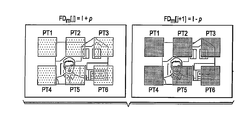
결합 프로세스(34a)는 프레임 j로부터의 시각적 페이로드 영상 데이터가 수신되는 프로세스(55a)로 시작한다. 도 4b는 청중이 보도록 의도되어 있는 시각적 콘텐츠를 보여주는, 이 영상 데이터 프레임 j에 대한 프레임 데이터 FD[j]의 예시적인 일례를 나타낸 것이다. 프로세스(56a)에서, 프레임 데이터 FD[j]는, 프로세스(52)에서 선택된 위치에서, 프로세스(54)에서 결정된 강도 Δ 값만큼 위치 확인 대상물 형상 내의 그 픽셀에 대한 강도 데이터를 수정함으로써 위치 확인 대상물과 결합된다. 이 프로세스(56a)에서, 프레임 j에 대해, 이 강도 Δ 값이, 픽셀별로, 그의 선택된 위치에서 위치 확인 대상물 형상 내의 각각의 픽셀에 대한 강도 값에 가산된다. 본 발명의 이 실시예에서, 위치 확인 대상물 밖에 있는 픽셀의 강도 값은 프로세스(56a)에서 수정되지 않는다. 환언하면, 디스플레이 위치 (x,y)에 있는 픽셀이 페이로드 영상 데이터에서 강도 값 Ix,y를 가지는 경우, 프로세스(56a)의 결과는 다음과 같이 수정된 픽셀 강도 값 Im_x,y를 생성할 것이다:The combining

도 4b는, 수정된 프레임 데이터 FDm[j]를 통해, 열십자 모양의 위치 확인 대상물(PT1)이 디스플레이된 영상의 우측 하부 사분면에서의 선택된 위치에서 더 밝은 값으로 보이는, 가산(56a)의 결과의 간략화된 일례를 나타낸 것이다. 프로세스(36a)에서, 프레임 j에 대한 이들 수정된 프레임 데이터 FDm[j]가 디스플레이를 위해 형식 설정되고, 디스플레이(20)에 디스플레이하기 위해 프로젝터(21)에 전달된다.FIG. 4B shows the
시각적 페이로드 영상 프레임 데이터의 그 다음 프레임 j+1에 대한 결합 프로세스(36b)는 위치 확인 대상물(들) 내의 픽셀에 대한 페이로드 강도로부터 강도 Δ 값을 차감한다. 프로세스(55b)에서, 시각적 페이로드 영상 프레임 데이터의 프레임 j+1이 수신되고, 도 4b의 간략화된 일례에서, 이 페이로드 영상 데이터가 프레임 j과 프레임 j+1 사이에서 실질적으로 변하지 않는 것으로 가정된다(즉, FD[j] = FD[j+1]). 프로세스(56b)에서, 위치 확인 대상물 내의 프레임 데이터 FD의 픽셀에 대한 강도 값 데이터가 픽셀 강도로부터 강도 Δ 값을 차감함으로써 수정된다. 위치 확인 대상물 밖에 있는 픽셀의 강도 값은 프로세스(56b)에서 수정되지 않는다. 상기한 바와 유사하게, 디스플레이 위치 (x,y)에 있는 픽셀이 페이로드 영상 데이터에서 강도 값 Ix,y를 가지는 경우, 프로세스(56b)의 결과는 수정된 픽셀 강도 값 Im_x,y를 생성한다.The combining

도 4b에 도시된 바와 같이, 수정된 프레임 데이터 FDm[j+1]은, 디스플레이된 영상의 우측 하부 사분면에서의 동일한 선택된 위치에서, 열십자 모양의 위치 확인 대상물(PT1)을 더 어두운 값으로서 포함한다. 프로세스(36b)에서, 프레임 j+1에 대한 이들 수정된 프레임 데이터 FDm[j+1]가 디스플레이를 위해 형식 설정되고, 디스플레이(20)에 디스플레이하기 위해 프로젝터(21)에 전달된다.As shown in Fig. 4B, the modified frame data FD m [j + 1] is used as a darker value for the crisscross positioning object PT1 at the same selected position in the lower right quadrant of the displayed image. Include. In
이 설명을 위해, 위치 확인 대상물에 적용되는 강도 수정이 단색과 관련하여 기술되어 있으며, 각각의 픽셀의 전체 강도가 위치 확인 대상물에서 더 밝게 또는 더 어둡게 변조되는 것으로 기술되어 있다. 물론, 최신의 디스플레이는 통상적으로 각각의 성분 컬러(예컨대, 적색, 녹색, 청색)에 대해 상이한 강도를 갖는 프레임 데이터에 기초하여 실현되는 컬러 디스플레이이다. 그에 따라, 본 발명의 일부 실시예에 대해, 각각의 성분 컬러의 강도가 위치 확인 대상물 위치에서 ±p만큼 변조되는 것이 생각되고 있다. 본 발명의 다른 실시예에서, 이하에서 더욱 상세히 기술될 것인 바와 같이, 변조가 컬러마다 달라질 것이다.For this description, the intensity correction applied to the positioning object is described with respect to a single color, and the overall intensity of each pixel is described as being lighter or darker modulated in the positioning object. Of course, modern displays are typically color displays realized on the basis of frame data having different intensities for each component color (eg red, green, blue). Thus, for some embodiments of the present invention, it is contemplated that the intensity of each component color is modulated by ± p at the location of the positioning object. In another embodiment of the present invention, the modulation will vary from color to color, as will be described in more detail below.
프레임 j 및 프레임 j+1로부터 결합 프로세스(34) 및 전달 프로세스(36)의 완료 시에, 도 4a에서 j=j+2로 증분시키고 그 다음 프레임 j+2에 대해 프로세스(55a)로 제어를 되돌려주는 것에 의해 나타낸 바와 같이 프로세스가 이어서 다음 프레임 j+2에 대해 반복된다. 그 결과, 영상 시퀀스가 디스플레이(20)에 디스플레이되고, 하나 이상의 위치 확인 대상물이 연속적인 프레임에서 나타나지만, 그 연속적인 프레임에서 교대로 밝아졌다 어두워졌다한다. 그렇지만, 사람의 눈의 응답은 일반적으로 너무 느려서 60 Hz 또는 그 이상 정도인 최신의 프레임 레이트의 개별 디스플레이 프레임을 인지하지 못한다(예컨대, 60 Hz 또는 그 이상의 디스플레이 리프레시 레이트에서 디스플레이 플리커는 일반적으로 사람의 눈에 보이지 않는다). 오히려, 사람 시청자는 인지되는 디스플레이된 영상을, 예를 들어, 다수의 시퀀스에 걸쳐 평균하는 경향이 있다. 도 4b를 참조하면, 이 평균의 결과는 연속적인 프레임 j,j+1을 합하고[가산기(61)] 이어서 시간에 걸쳐 강도를 평균한 것이다. 위치 확인 대상물 내의 그 픽셀에 대해, 2 프레임에 걸친 이러한 평균은 다음과 같이 된다:Upon completion of the combining

그에 따라, 사람 시청자는 자연스럽게 시각적 페이로드 영상 데이터만을 인지하고, 위치 확인 대상물 또는 형상을 직접 인지하지 않는다.Thus, the human viewer naturally perceives only visual payload image data and does not directly recognize the positioning object or shape.
그렇지만, 본 발명의 실시예에 따르면, 대화형 디스플레이 시스템은 디스플레이된 영상(I) 내에 포함된 위치 확인 대상물을 검출하고 식별할 수 있다. 검출 프로세스(40)의 일례에 대해 이제부터 도 4c를 참조하여 기술할 것이다.However, according to an embodiment of the present invention, the interactive display system may detect and identify the positioning object included in the displayed image I. FIG. An example of the
본 발명의 이 실시예에 따르면, 포인팅 장치(10)의 카메라 및 영상 캡처 기능부는 종래의 상업적으로 이용가능한 "웹캠" 구성요소를 사용하여 구성될 수 있다. 동기화(또는 보다 정확하게는, 비동기 동작)의 용이함을 위해, 포인팅 장치(10)의 영상 캡처 기능부(16)가 디스플레이(20)의 프레임 레이트의 약 2배 또는 그 이상인 프레임 레이트로 동작하는 것이 바람직하다. 이 영상 캡처 프레임 레이트에서, 포인팅 장치(10)는 프로세스(60)에서 영상 프레임 m을 캡처하고 이어서 프로세스(62)에서 영상 프레임 m+2(영상 캡처 프레임 레이트에서 2개 프레임 이후임)를 캡처하는 동작을 한다. 2개의 영상 캡처 샘플 주기만큼 분리되어 있는 프로세스(60, 62)의 이 동작은 캡처된 영상 프레임 m+2가 캡처된 영상 프레임 m(예컨대, 도 4b의 프레임 데이터 FDm[j+1] 및 프레임 데이터 FDm[j])과 정반대의 강도 Δ 값을 갖는 위치 확인 대상물이 오버레이되어 있는 영상을 캡처하도록 한다.According to this embodiment of the present invention, the camera and image capture function of the
프로세스(64)에서, 위치 확인 회로(25)[도 2a에서와 같이 컴퓨터(22)에 위치하거나 도 2b에서와 같이 포인팅 장치(10')에 위치함]는, 픽셀별로, 캡처된 영상 프레임 m+2의 영상 데이터를 캡처된 영상 프레임 m으로부터 차감한다. 도 4b에 도시된 바와 같이, 차감(64)의 결과, 시각적 페이로드 영상 데이터가 효과적으로 상쇄되고, 위치 확인 대상물(PT1)이 강화된다. 이상적인 경우에, 차감 프로세스(64)의 결과, 다음과 같은 인지된 강도 값이 얻어진다:In

그에 따라, 차감 프로세스(64) 후에, 위치 확인 장치(10)가 위치 확인 대상물 또는 형상만 인지하고, 시각적 페이로드 영상 데이터는 인지하지 않는다. 또한, 노이즈 감소를 위해 원하는 경우, 위치 확인 대상물을 복원하기 위해 3개 이상의 프레임이 캡처되고 차감될 수 있는 것이 생각되고 있다. 예를 들어, 프레임 m 및 프레임 m+1이 서로 합산될 수 있고, 프레임 m+2 및 프레임 m+3이 서로 합산될 수 있으며, 이 합산된 프레임들의 차가 위치 확인 대상물을 복원하는 데 사용될 수 있다. 이들 및 기타 변형례가 본 발명의 실시예의 범위에 속하는 것으로 생각된다.Thus, after the
종래의 캡처된 영상 처리가 이어서 차감 프로세스(64)의 결과에 적용된다. 도 4c에 도시된 본 발명의 실시예에서, 프로세스(66)에서, 히스토그램 등화 필터가 적용된다. 기술 분야에 공지된 바와 같이, 경우에 따라 차감 프로세스(64) 이후에, 이 히스토그램 등화가 픽셀 강도의 압축된 범위에서 비디오 데이터를 보정한다. 히스토그램 등화 필터 프로세스(66)는 강도 범위에 걸쳐 그 분포를 균등하게 하기 위해 본질적으로 픽셀 강도를 재분산시킨다. 프로세스(68)에서, 디지털 워터마크 삽입 및 검출의 기술 분야에 공지된 바와 같이, 기하학적 왜곡을 보정하기 위해 종래의 적응적 동기화가 필터링된 위치 확인 대상물 영상 데이터에 적용된다. 원하는 바에 따라, 다른 영상 처리 기법도 역시 적용될 수 있다.Conventional captured image processing is then applied to the results of the
캡처된 영상 프레임 m 및 m+2로부터 위치 확인 대상물 영상을 복원하고 처리할 시에, 존재하는 경우, 처리된 영상 데이터에서의 위치 확인 대상물 특징부를 식별하기 위해 프로세스(70)가 이어서 위치 확인 회로(25)에 의해 수행된다. 기지의 위치 확인 대상물 형상과 일치하는 형상이 처리된 캡처된 영상 데이터에 존재하는지를 판정하기 위해 데이터의 분석에 의해 이 식별이 수행될 수 있다. 이러한 위치 확인 대상물이 식별되면, 프로세스(70)는 또한 캡처된 위치 확인 대상물의 다양한 속성 - 캡처된 영상에서의 그의 x-y 위치, 위치 확인 대상물 특징부의 크기, 그의 회전 배향, 임의의 형상 왜곡[어떤 각도에서 디스플레이(20)를 보는 것을 나타낼 수 있음] 등을 포함함 - 을 결정한다. 본 발명의 이 실시예에 따르면, 속성 결정 프로세스(40)(도 3a)가 이와 같이 완료된다. 도 3a와 관련하여 앞서 기술한 바와 같이, 검출된 속성이 이어서 대화식 명령의 위치 확인 및 식별을 완료하는 데 사용된다.In reconstructing and processing the positioning object image from the captured image frames m and m + 2, if present, the
따라서, 본 발명의 이 실시예에 따르면, 디스플레이(20)에 디스플레이된 영상에서의 하나 이상의 위치 확인 대상물 특징부가 위치 확인 회로(25)에게는 인지가능하지만 청중(A)에게는 인지가능하지 않은 방식으로 발생되고 검출된다. 그에 부가하여, 이 동작이, 프로젝터 또는 기타 디스플레이(20)의 수정을 필요로 함이 없이, 종래의 공칭 디스플레이 프레임 레이트로 수행된다. 그에 따라, 본 발명의 실시예가, 다양한 유형의 디스플레이와 관련하여, 광범위하게 설치되어 있는 기존의 디스플레이에 대해 사용될 수 있다. 게다가, 본 발명의 실시예에 따른 사람이 인지할 수 있는 위치 확인 대상물의 부존재는 대화형 디스플레이 시스템이 사용될 수 있는 거리의 범위를 증가시킬 수 있으며, 이에 대해서는 도 5a 및 도 5b를 참조하여 이제부터 기술할 것이다.Thus, according to this embodiment of the present invention, one or more positioning object features in the image displayed on the
도 5a에 도시된 바와 같이, 포인팅 장치(10)가 디스플레이(20)에 비교적 가까이 있다. 그에 따라, 포인팅 장치(10)의 시야(FOV)가 비교적 작고, 단일 위치 확인 대상물(PT)을 포함한다. 이 위치 확인 대상물(PT)은 포인팅 장치에 의해 캡처된 영상 내에서 비교적 크게 보일 것이다. 그에 따라, 위치 확인 회로(25)는 포인팅 장치(10)가 가리키고 있는 디스플레이(20)의 위치를 추론할 수 있을 뿐만 아니라, 포인팅 장치(10)에 의해 캡처되고 복원된 영상 내에서의 단일 위치 확인 대상물(PT)의 크기로부터, 포인팅 장치(10)가 디스플레이(20)로부터 단지 가까운 거리만큼 떨어져 있다는 표시를 추론할 수 있다. 이와 달리, 도 5b의 일례에서는, 포인팅 장치(10)가 디스플레이(20)로부터 비교적 멀리 떨어져 있다. 그에 따라, 포인팅 장치(10)의 보다 큰 시야(FOV)는, 이 일례에서, 다수의 위치 확인 대상물(PT1, PT2) - 이들 각각은 (도 5a의 경우에 비해) 포인팅 장치(10)에 의해 캡처된 영상 내에서 비교적 작은 것처럼 보임 - 을 포함한다. 위치 확인 대상물(PT1 내지 PT6)은, 위치 확인 프로세스에 도움을 주기 위해, 서로 상이한 형상 또는 배향을 가질 수 있다(도시 생략). 다시 말하지만, 위치 확인 회로(25)는 가리킨 위치[즉, 시야(FOV)의 중앙]를 결정할 수 있을 뿐만 아니라, 캡처되고 복원된 영상 내의 위치 확인 대상물(PT1, PT2)의 수 및 크기를 결정할 수 있다.As shown in FIG. 5A, the
또한, 디스플레이 및 위치 확인 프로세스가 동적인 방식으로 - 대상물 발생기 기능부(23)가 위치 확인 프로세스의 이전의 반복에 의존하는 위치, 크기 및 모습으로 위치 확인 대상물을 발생함 - 수행될 수 있는 것이 생각되고 있다. 위치 확인 대상물의 이러한 동적 발생의 일례에 대해 도 13a 내지 도 13e와 관련하여 이하에서 기술할 것이다.It is also contemplated that the display and positioning process can be performed in a dynamic manner, where the
본 발명의 실시예에 따르면, 대화형 디스플레이 시스템의 사용자는 이와 같이, 디스플레이(20)로부터 먼 거리에 떨어져 있든 디스플레이(20)에 다가가거나 심지어 디스플레이(20)를 터치하든 간에, 디스플레이(20)에 디스플레이된 특정의 가상 "버튼", 링크 또는 기타 콘텐츠를 가리키는 것에만 기초하여, 디스플레이(20)에 디스플레이된 시각적 콘텐츠와 상호작용할 수 있다. 이러한 방식으로, 사용자는 그래픽 사용자 인터페이스("GUI")에 대응하는 방식으로 시각적 콘텐츠와 상호작용할 수 있다. 이 상호작용의 다양한 적용이 생각되고 있다. 연설자는, 활성 콘텐츠(예컨대, 인터넷 링크, 활성 아이콘, 가상 버튼, 스트리밍 비디오 등)를 선택하여 프레젠테이션의 고급 그래픽 및 제어를 작동시킴으로써, 디스플레이(20)에 디스플레이되는 프레젠테이션과 상호작용할 수 있다. "선택", 클릭 앤 드래그, 우측 클릭, 디스플레이된 콘텐츠의 줌인 또는 줌아웃, 페이지 넘기기 등과 같은 그래픽 사용자 인터페이스 명령이 디스플레이(20)의 결정된 가리킨 위치에 기초하여 포인팅 장치(10)로부터 전달되도록 되어 있다.According to an embodiment of the present invention, a user of an interactive display system may thus be connected to the
다른 상황에서, 포인팅 장치(10)가 사용자가 컴퓨터(22)에 의해 실행되는 컴퓨터 게임을 조작하고 플레이할 수 있게 해주는 게임 컨트롤러로서 사용될 수 있고, 이와 관련하여, 포인팅 장치(10) 내에 포함되어 있는 가속도계 등과 같은 관성 센서가 사용자로부터 게임으로의 입력을 향상시키기 위해 사용될 수 있다.In other situations, the
다른 상황에서, 포인팅 장치(10)가 디스플레이된 콘텐츠 상에(예를 들어, 그 콘텐츠를 하이라이트하거나 그 콘텐츠에 관한 주석을 첨부하기 위해) 또는 비어 있는 "화이트 보드" 디스플레이 상에 손으로 이미지 그리기 및 손으로 글씨 쓰기와 관련한 명령을 발행하는 데 사용될 수 있다. 특히 본 출원에서는, 사용자가 [예를 들어, 포인팅 장치(10) 자체를 사용하여 디스플레이(20)에 있는 아이콘을 가리키는 것을 통해] "기록" 명령을 발행할 수 있는 것 - 그에 응답하여, 컴퓨터(22)는 데이터를 그의 메모리 자원들 중 하나의 메모리 자원에 저장하는 동작을 하고, 저장된 데이터는 디스플레이(20)에 대해 포인팅 장치(10)에 의해 행해진 "가상" 쓰기 또는 그리기("virtual" writing or drawing)를 저장하는 것을 비롯한 포인팅 장치(10)의 후속 동작에 대응함 - 이 생각되고 있고, 그에 부가하여, 사용자 또는 청중이 말한 음성이 또한 저장된 가상 쓰기 또는 그리기에 대응하도록 기록될 수 있는 것이 생각되고 있다.In other situations, the
이들 그래픽 사용자 인터페이스 상황 중 임의의 상황에서, 포인팅 장치(10)를 통해 발행된 사용자로부터의 명령이 대화적으로 컴퓨터(22)에 응답할 수 있다 - 일반적으로 수신된 사용자 명령에 응답하여 디스플레이될 새로운 시각적 페이로드 영상 콘텐츠를 발생함 -. 앞서 기술한 바와 같이, 디스플레이, 위치 확인 및 응답 프로세스 전체가 이어서 반복된다.In any of these graphical user interface situations, commands from the user issued through the
본 발명과 관련하여, 앞서 기술한 바와 같이, 본 발명의 실시예에 따르더라도, 디스플레이된 영상에서 위치 확인 대상물 영상으로 인한 어떤 수차가 사람 청중에 의해 인지될 수 있다는 것이 관찰되었다. 본 발명의 다양한 부가의 실시예에 따르면, 이들 눈에 보이는 수차를 추가적으로 감소시켜 청중에 대한 위치 확인 대상물의 비인지성을 개선시키고 따라서 청중의 경험을 추가로 향상시키는 방식으로 위치 확인 대상물이 발생될 수 있다. 본 발명의 이들 다양한 부가의 실시예에 대해 이제부터 더욱 상세히 기술할 것이며, 청구된 본 발명의 범위 내에서, 본 발명의 이들 실시예 각각이 개별적으로 또는 서로 임의로 조합하여 또는 다른 변형례와 결합되어 사용될 수 있다는 것을 잘 알 것이다.In connection with the present invention, as described above, it has been observed that even according to an embodiment of the present invention, any aberration due to the positioning object image in the displayed image may be perceived by the human audience. According to various additional embodiments of the present invention, positioning objects can be generated in such a way as to further reduce these visible aberrations to improve the perception of the positioning object to the audience and thus further enhance the experience of the audience. have. These various additional embodiments of the invention will now be described in more detail, and within the scope of the claimed invention, each of these embodiments of the invention may be individually or in any combination with each other or in combination with other variations. It will be appreciated that it can be used.
역감마 위치 확인 대상물 발생Reverse gamma positioning object occurrence
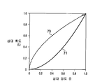
본 발명에 따르면, 전술한 일반화된 개념(즉, 위치 확인 대상물에서의 각각의 픽셀에 대한 강도 D 값의 단순한 가산 및 차감)에 따라 발생된 위치 확인 대상물로 인해, 위치 확인 대상물이 페이로드 영상의 비교적 밝은 영역에서 사람 시청자에게 보이게 될 수 있고, 이와 달리, 페이로드 영상의 보다 어두운 영역에서 위치 확인 대상물이 포인팅 장치에게 잘 보이지 않게 될 수 있다는 것이 관찰되었다. 이들 아티팩트는 디스플레이 프로세스에서의 감마 보정으로 인한 것이다. 기술 분야에 공지된 바와 같이, 디스플레이되는 각각의 픽셀의 강도가 그래픽 어댑터(27)의 출력에 대한 선형 응답에 기초하지 않는다. 오히려, 픽셀에 대한 디스플레이된 휘도 L(I)가 디지털 강도 값(I)(범위 [0, 1]로 정규화되어 있음)의 함수이도록 "감마" 보정 함수가 적용된다:According to the present invention, due to the positioning object generated according to the generalized concept described above (i.e., simple addition and subtraction of the intensity D value for each pixel in the positioning object), the positioning object is generated from the payload image. It has been observed that in a relatively bright area it can be seen by human viewers, whereas in the darker areas of the payload image the positioning object may be less visible to the pointing device. These artifacts are due to gamma correction in the display process. As is known in the art, the intensity of each pixel displayed is not based on a linear response to the output of the
![]()
![]()
여기서 C는 디스플레이(20)의 최대 밝기에 관련된 상수이고, b는 블랙 레벨(black level)이며, γ는 디스플레이(20)의 비선형성(non-linearity)(통상적으로 1.5 내지 2.2의 범위에 있음)이다. 이 감마 보정 함수 L(I)의 일례가 도 6a의 곡선(71)으로 나타내어져 있다. 그에 따라, 강도(I)가 1보다 0에 더 가까울 때, 강도 Δ 값 p에 의한 강도(I)의 변조가 얻어진 휘도 L(I)에 영향을 덜 미친다. 이와 달리, 강도(I)가 1보다 1에 가까울 때, 강도 Δ 값 p에 의한 강도(I)의 변조가 얻어진 휘도 L(I)에 영향을 더 미친다. 이 결과, 위치 확인 대상물이 페이로드 영상의 밝은 영역에서 보이게 되거나(I가 1에 가까움) 페이로드 영상의 어두운 영역에서 복원하기 어렵게 된다(I가 0에 가까움).Where C is a constant related to the maximum brightness of the
본 발명의 이 실시예에 따르면, 강도 Δ 값 p를 디지털 강도 값(I)의 함수로서 표현함으로써 위치 확인 대상물이 발생되고 적용되며, 이 함수 p(I)는 감마 보정 함수를 보상한다. 이 동작이 도 6b에 도시되어 있으며, 프로세스(32)(도 4a)에서의 위치 확인 대상물의 발생이, 이전과 같이, 위치 확인 대상물 형상의 검색[프로세스(50)] 및 위치 확인 대상물의 위치의 선택[프로세스(52)]으로 시작된다. 프로세스(54')에서, 적색, 녹색 및 청색 컬러 성분 각각에 대한 위치 확인 대상물에 대해 패턴 강도 Δ 기준값(pr, pg, pb)이 선택된다. 이들 기준값(pr, pg, pb)은 위치 확인 대상물에서의 시각적 페이로드 영상 강도 데이터에 적용되어질 함수 p(I)를 정의한다.According to this embodiment of the present invention, a positioning object is generated and applied by representing the intensity Δ value p as a function of the digital intensity value I, which compensates the gamma correction function. This operation is shown in FIG. 6B, where the occurrence of the positioning object in the process 32 (FIG. 4A), as before, is performed by searching of the positioning object shape (process 50) and positioning of the positioning object. It begins with selection (process 52). In
프로세스(56a)는, 이상에서 기술한 바와 같이, 위치 확인 대상물 오버레이를 시각적 페이로드 영상 데이터의 프레임 j에 적용한다. 본 발명의 이 실시예에서, 이 프로세스(56a)는 페이로드 영상에서의 각각의 픽셀에 대한 그리고 특히 위치 확인 대상물에서의 각각의 픽셀에 대한 수신된 강도 값 Ir,g,b에 기초한다. 프로세스(72a)에서, 대상물 발생기 기능부(23)는, 감마 보정 함수에 따라 그 픽셀에 대한 강도 값 Ir에 응답하여, 위치 확인 대상물 위치에서의 적색 성분에 대한 강도 Δ 값 pr'(Ir)를 계산한다:

이 역감마 보정 함수의 일례가 도 6a에서 곡선(73)으로 표시되어 있다. 수신된 강도 값 Ig, Ib에 각각 응답하여, 녹색 및 청색 성분에 대한 강도 Δ 값 pg'(Ig), pb'(Ib)가 이와 유사하게 계산된다. 다른 대안으로서, 픽셀 밝기 값이 상이한 컬러에 대한 상이한 사람 민감도를 고려하는 수식에 기초하여 계산될 수 있고, 역감마 보정이 이어서 이 픽셀 밝기 값에 적용될 수 있다.An example of this inverse gamma correction function is shown by the
프로세스(74a)에서, 프로세스(72)로부터 얻어지는 강도 Δ 값 pr'(Ir), pg'(Ig), pb'(Ib)가 프레임 j의 위치 확인 대상물 위치에서의 각각의 픽셀에 대한 수신된 강도 값 Ir,g,b에 가산된다. 이와 유사하게, 프로세스(72b)는 다음 프레임 j+1의 위치 확인 대상물 위치에서의 각각의 픽셀에 대한 강도 Δ 값 pr'(Ir), pg'(Ig), pb'(Ib)를, 그 위치에서의 각각의 픽셀에 대한 수신된 강도 값 Ir,g,b에 응답하여, 계산한다. 프로세스(74b)에서, 프로세스(72b)에서 계산된 강도 Δ 값 pr'(Ir), pg'(Ig), pb'(Ib)를 차감함으로써, 프레임 j+1의 위치 확인 대상물에서의 각각의 픽셀에 대한 수신된 강도 값 Ir,g,b가 수정된다. 각각의 경우에, 수정된 프레임 강도 데이터가 적절한 경우 그래픽 어댑터(27)에 의해[디스플레이(20)에 대한 감마 함수에 따르는 것을 포함함] 형식 설정되고, 이어서 프로세스(36a, 36b)(도 4a)에서 프로젝터(21)로 또는 제시를 위해 디스플레이(20)로 곧바로 전달된다.In
따라서, 본 발명의 이 실시예에 따르면, 페이로드 영상 데이터의 밝은 영역에서 위치 확인 대상물의 사람 인지성이 감소되면서, 그 영상의 어두운 영역에서 그 위치 확인 대상물의 검출성(detectability)을 유지한다. 또한, 본 발명의 이 실시예에 따른 역감마 보정이 또한 보다 작은 기준 강도 Δ 값 p의 사용을 가능하게 해주고, 따라서 청중이 보는 영상에서의 위치 확인 대상물 아티팩트의 존재를 추가적으로 감소시키는 것이 생각되고 있다.Thus, according to this embodiment of the present invention, the human perception of the positioning object in the bright area of the payload image data is reduced, while maintaining the detectability of the positioning object in the dark area of the image. It is also contemplated that inverse gamma correction according to this embodiment of the present invention also enables the use of smaller reference intensity Δ values p, thus further reducing the presence of positioning object artifacts in the image seen by the audience. .
위치 확인 대상물의 분산된 플리커 영역Distributed flicker area of the positioning object
Park 등의 "Undistorted Projection onto Dynamic Surface", Advances in Image and Video Technology (2006), pp. 582 - 90에서, 페이로드 영상이 실제의 실세계 객체 및 표면에 투사되는 응용에서, 기하 보정을 위해 패턴 영상이 디스플레이된 영상 내에 삽입된다. 그 논문에 기술된 바와 같이, "증강 현실"을 위해, 패턴 영상이 전체 화면을 채운다. 그렇지만, Watson 등의 "Window of visibility: a psychophysical theory of fidelity in time-sampled visual motion displays", J. Opt. Soc. Am., Vol. 3, No. 3 (March, 1986), pp. 300 - 07에 기술된 바와 같이, 강도를 변경하는 큰 디스플레이 영역의 플리커의 느낌에 더 민감하다는 것이 알려져 있다.Park et al., "Undistorted Projection onto Dynamic Surface", Advances in Image and Video Technology (2006), pp. At 582-90, in applications where payload images are projected onto real real-world objects and surfaces, pattern images are inserted into the displayed images for geometric correction. As described in the paper, for "augmented reality", the pattern image fills the entire screen. Nevertheless, Watson et al., "Window of visibility: a psychophysical theory of fidelity in time-sampled visual motion displays", J. Opt. Soc. Am., Vol. 3, No. 3 (March, 1986), pp. As described in 300-07, it is known that it is more sensitive to the feeling of flicker in large display areas of varying intensity.
따라서, 본 발명의 다른 실시예에 따르면, 위치 확인 대상물이, 영상 프레임 전체보다는, 각각의 디스플레이된 영상 프레임의 일부분만을 덮고 있다. 도 7은 정사각형을 기본적인 위치 확인 대상물(PT1 내지 PT6)로서 사용하여, 이 감소된 적용 범위의 일례를 나타낸 것이다. 물론, 이상에서 기술한 바와 같이, 특정의 위치 확인 대상물(PT) 형상은, 포인팅 장치(10)의 배향의 검출을 용이하게 해주기 위해, 다양한 위치 확인 대상물(PT1 내지 PT6)을 서로 구분하기 위해, 또한 포인팅 장치(10)의 축을 벗어난 위치를 검출하기 위해, 일반적으로 정사각형 이외의 무언가일 것이다. 어쨋든, 수정된 영상 프레임 데이터 FDm[j], FDm[j+1]의 일례에 대해 도 7로부터 명백한 바와 같이, 위치 확인 대상물(PT1 내지 PT6)은 디스플레이된 페이로드 영상의 전체 영역보다 적게 덮고 있다. 디스플레이 영역 전체보다 적게 덮고 있지만 훨씬 더 많은 위치 확인 대상물(PT)이 구현될 수 있는 것이 생각되고 있다.Thus, according to another embodiment of the invention, the positioning object covers only a portion of each displayed image frame, rather than the entire image frame. 7 shows an example of this reduced coverage, using the square as basic positioning objects PT1 to PT6. Of course, as described above, the specific positioning object PT shape is used to distinguish the various positioning objects PT1 to PT6 from each other in order to facilitate detection of the orientation of the
그 결과, 전체 디스플레이 영역의 일부분만이 프레임마다 변조된 강도로 디스플레이되는 것을 고려하여, 청중에 의해 인지될지도 모르는 디스플레이 플리커 느낌이 본 발명에 따라 감소되는 것이 생각되고 있다. 따라서, 위치 확인 대상물 영상의 비인지성이 향상된다.As a result, considering that only a portion of the entire display area is displayed at a modulated intensity per frame, it is contemplated that the display flicker feeling that may be perceived by the audience is reduced in accordance with the present invention. Therefore, the non-perception of the positioning object image is improved.
위치 확인 대상물의 패턴의 비패턴화Unpatterned pattern of positioning object
Watson 등의 "What does the eye see best?", Nature, 302(5907) (1983), pp. 419 - 22에 기술된 바와 같이, 사람의 눈은 어떤 공간 주파수로 발생하는 패턴에 민감하다. 본 발명에 따르면, 패턴이 명백히 규칙적인 경우 그렇지 않았으면 인지되지 않았을 패턴이 인기가능하게 되는 것에 의해 이 효과가 관찰되었다. 본 발명의 이 실시예에 따르면, 상이한 공간 주파수로 위치 확인 대상물의 보다 흐릿한 패턴을 발생하여 오버레이함으로써 위치 확인 대상물의 패턴의 규칙성이 방해된다. 이제 도 8을 참조하여, 본 발명의 이 실시예에 따라 불규칙적인 공간 주파수로 위치 확인 대상물을 발생하는 것에 대해 이제부터 기술할 것이다. 상세하게는, 본 발명의 이 실시예가 위치 확인 대상물이 전술한 바와 같이 발생되는 프로세스(32)(도 3a) 내에서 구현된다."What does the eye see best?", Watson et al., Nature, 302 (5907) (1983), pp. As described in 419-22, the human eye is sensitive to patterns that occur at any spatial frequency. According to the present invention, this effect was observed by making the pattern popular, which would otherwise not be recognized if the pattern was clearly regular. According to this embodiment of the present invention, the regularity of the pattern of the positioning object is disturbed by generating and overlaying a blurry pattern of the positioning object at different spatial frequencies. Referring now to FIG. 8, a description will now be given of generating a positioning object at an irregular spatial frequency in accordance with this embodiment of the present invention. Specifically, this embodiment of the present invention is implemented within the process 32 (FIG. 3A) in which the positioning object is generated as described above.
본 발명의 이 실시예에서의 위치 확인 대상물의 발생은 위치 확인 대상물의 1차 패턴의 패턴 형상 또는 형상들이 메모리로부터 검색되거나 대상물 발생기 기능부(23)에 의해 다른 방식으로 발생되는 프로세스(50a)로 시작한다. 프로세스(52a)에서, 1차 위치 확인 대상물이 디스플레이되어야 하는 영상의 위치가 선택되고, 본 발명의 이 실시예에서, 1차 위치 확인 대상물 패턴(PTP1)에 의해 나타낸 바와 같이, 이 패턴이 공간적 의미에서 본질적으로 주기적이다. 이상에서 기술한 바와 같이, 프로세스(54a)에서, 대상물 발생기 기능부(23)는 이 1차 위치 확인 대상물 패턴에 대한 강도 Δ 값 p1을 선택한다. 이 강도 Δ 값 p1은 다시 말하지만 위치 확인 대상물 내의 픽셀 위치에서의 페이로드 영상 데이터로부터의 강도의 편차(플러스 또는 마이너스)에 대응한다.The generation of the positioning object in this embodiment of the present invention is carried out by a
프로세스(60)에서, 경우에 따라, 1차 위치 확인 대상물 패턴의 2차원 공간 주파수 fxy1가 결정되거나 검색된다. 이 공간 주파수가 영상 처리 응용에 대한 종래의 방식으로 결정될 수 있는 것이 생각되고 있다. 프로세스(50b)는 1차 위치 확인 대상물 패턴에 오버레이할 위치 확인 대상물의 2차 패턴의 발생은 물론, 역시 페이로드 영상 데이터의 발생도 시작한다. 본 발명의 이 실시예에 따르면, 이 2차 패턴은, 예를 들어, 1차 패턴의 공간 주파수 fxy1보다 더 높은 2차원 공간 주파수 fxy2를 가질 것이다:In

물론, 다른 대안으로서, 9/4 이외의 다른 공간 주파수 배수가 사용될 수 있다. 프로세스(52b)에서, 디스플레이된 영상의 경계가 주어지고 개별 요소에 대한 형상이 선택될 시에, 이 2차 패턴이 이어서 오버레이로서 발생된다. 도 8에 나타낸 바와 같이, 이 일례에서, 2차 패턴(PTP2)에서의 위치 확인 대상물 각각은 원형인 반면, 1차 패턴(PTP1)에서의 위치 확인 대상물은 정사각형이다. 마지막으로, 프로세스(54b)에서, 이 2차 패턴에 대한 2차 강도 Δ 값 p2가 선택된다. 이 2차 강도 Δ 값 p2가 크기가 1차 강도 Δ 값 p1보다 작은 것이 생각되고 있다.Of course, as another alternative, a spatial frequency multiple other than 9/4 may be used. In
다른 대안으로서, 보다 복잡한 위치 확인 대상물 패턴이 2차 패턴(PTP2)으로서 적용될 수 있다. 예를 들어, 2차원 가우시안 곡선의 패턴이, 비인지성의 관점에서 볼 때, 효과적인 마스킹 패턴을 생성하는 것으로 관찰되었다. 그렇지만, 이러한 복잡도가 더 높은 2차 마스킹 패턴은 위치 확인 대상물의 검출을 복잡하게 할 수 있다.As another alternative, a more complex positioning object pattern may be applied as the secondary pattern PTP2. For example, it has been observed that the pattern of the two-dimensional Gaussian curve produces an effective masking pattern in terms of non-cognition. However, this higher complexity secondary masking pattern can complicate the detection of the positioning object.
도 8은 또한 위치 확인 대상물 1차 및 2차 패턴(PTP1,PTP2)이 프레임 j의 페이로드 영상 데이터에 오버레이되는 결합 프로세스(34a)의 결과의 간략화된 일례를 나타낸 것이다. 이 일례에서, 1차 강도 Δ 값 p1 및 2차 강도 Δ 값 p2가 페이로드 영상 데이터의 픽셀 패턴(의 강도)에 가산될 것이다. 어떤 픽셀은 1차 강도 Δ 값 p1 가산자(adder) 및 2차 강도 Δ 값 p2 가산자 둘 다를 받을 것이고, 다른 픽셀은 이들 가산자 중 한쪽 또는 다른 한쪽을 받을 것이며, 다른 픽셀은 페이로드 영상 데이터에 의해 결정된 그의 강도에 그대로 있을 것이다. 이 일례에서, 얻어진 프레임 영상 데이터 FDm[j]가 도 8에 간략화된 형태로 나타내어져 있다.8 also shows a simplified example of the result of the combining
본 발명의 이 실시예에 따르면, 위치 확인 대상물의 2차 패턴(PTP2)에 의해 시행되는 불규칙성은, 위치 확인 대상물의 1차 패턴에 존재할 수 있는 공간 주기성을 방해함으로써, 위치 확인 대상물을 청중이 인지할 수 없게 렌더링하는 데 도움을 준다. 그에 부가하여, 1차 및 2차 위치 확인 대상물의 오버레이가, 위치 확인 대상물을 서로 구분시켜 줌으로써, 위치 확인 프로세스에 도움을 줄 수 있다는 것이 관찰되었다. 도 8의 일례에서, 오버레이는 1차 패턴(PTP1) 내의 어떤 2개의 정사각형도 비슷하지 않도록 패턴을 렌더링할 수 있다. 이 정보가 영상 캡처 시에 개별 위치 확인 패턴을 검출하는 데 그리고 포인팅 장치(10)가 가리킨 위치를 결정하는 데 적용될 수 있다.According to this embodiment of the present invention, the irregularity enforced by the secondary pattern PTP2 of the positioning object interferes with the spatial periodicity that may exist in the primary pattern of the positioning object, thereby allowing the audience to recognize the positioning object. It helps render it impossible. In addition, it has been observed that an overlay of primary and secondary positioning objects can assist in the positioning process by distinguishing the positioning objects from one another. In the example of FIG. 8, the overlay may render the pattern such that no two squares in the primary pattern PTP1 are similar. This information can be applied to detect individual positioning patterns upon image capture and to determine the location pointed to by the
배경 뒤집기Flip background
도 7과 관련하여 이상에서 기술한 바와 같이, 디스플레이(20) 전체를 채우지 않는 반복하는 패턴의 형태로 되어 있는 위치 확인 대상물(PT)은 사람 청중에 대한 위치 확인 대상물의 인지성을 감소시키는 데 도움을 준다. 도 9를 참조하여 이제부터 기술하게 될 본 발명의 다른 실시예에 따르면, 위치 확인 대상물(PT)의 검출성을 감소시키는 일 없이, 위치 확인 대상물의 비인지성이 추가로 향상된다. 보다 구체적으로는, 본 발명의 이 실시예에 따르면, 또한 위치 확인 대상물 밖에 있는 픽셀에 대한 픽셀 강도를 반대 방향으로 변조함으로써, 위치 확인 대상물(PT) 내의 픽셀에 대한 픽셀 강도의 변조의 진폭이 1/2만큼 감소될 수 있다.As described above with respect to FIG. 7, the positioning object PT in the form of a repeating pattern that does not fill the
본 발명의 이 실시예에 따라 시각적 페이로드 영상 데이터에 위치 확인 대상물(PT)을 적용하는 프로세스(34a, 34b)는 디스플레이된 영상의 프레임 j에 대한 프레임 데이터 FD[j]가 수신되는 프로세스(55a)로 시작한다. 프로세스(56a')에서, 이 프레임 j에 대해, 보다 작은 강도 Δ 값이, 픽셀별로, 그의 선택된 위치에서 위치 확인 대상물 형상 내의 각각의 픽셀에 대한 강도 값에 가산된다. 이 일례에서, 선택된 변조 강도 Δ 값 p에 대해, 위치 확인 대상물 형상 내에서의 강도의 가산은 p/2이다. 프로세스(57a)에서, 위치 확인 대상물 위치 및 형상 밖에 있는 픽셀에 대한 강도 값도 역시, 본 발명의 이 실시예에서, 그 픽셀 강도로부터 감소된 변조 강도 Δ 값 p/2를 차감함으로써 수정된다. 이상에서 기술한 바와 같이, 프로세스(56a', 57a)는, 원하는 경우, 각각의 성분 컬러에 대한 강도 값을 이들 양만큼 변조할 수 있다. 그 결과, 위치 확인 대상물 내에 있는 픽셀과 위치 확인 대상물 밖에 있는 픽셀 사이의 강도 차이는 p인 채로 있지만, 페이로드 데이터로부터의 임의의 픽셀 강도의 최대 편차는 p/2로 제한된다. 따라서, 프레임 j에서, 이 일례에 따르면, 수정된 픽셀 강도가 다음과 같이 표현된다:According to this embodiment of the present invention, the

프로세스(36a)에서, 수정된 프레임 데이터 FDm[j]는 이어서 형식 설정되고, 제시를 위해 디스플레이(20)에 전달된다.In
프로세스(55b)에서, 다음 프레임 j+1에 대한 프레임 데이터 FD[j+1]가 수신된다. 이 프레임 데이터 FD[j+1]도 이와 유사하게 수정되지만, 프레임 j에 적용되는 것과 반대 극성으로 수정된다. 프로세스(56b')는 위치 확인 대상물 내에 있는 각각의 픽셀에 대한 강도 값으로부터 감소된 변조 강도 Δ 값 p/2를 차감하고, 프로세스(57b)는 위치 확인 대상물 밖에 있는 각각의 픽셀에 대한 픽셀 강도에 감소된 변조 강도 Δ 값 p/2를 가산한다. 따라서, 이 프레임 j+1에 대해, 수정된 픽셀 강도는 다음과 같이 표현된다:In

프로세스(36b)에서, 수정된 프레임 데이터 FDm[j+1]는 이어서 형식 설정되고, 제시를 위해 디스플레이(20)에 전달된다.In
당업자가 본 명세서를 참조하면 위치 확인 대상물의 검출에서 수정된 프레임 데이터 FDm[j]와 수정된 프레임 데이터 FDm[j+1]의 차이를 구하는 것이, 이전과 같이, 위치 확인 대상물을 복원할 것이고, 페이로드 영상 데이터가 다시 말하지만 이 차감에 의해 상쇄된다는 것을 잘 알 것이다. 이와 달리, 사람 시청자에 의한 디스플레이된 수정된 프레임 데이터 FDm[j] 및 수정된 프레임 데이터 FDm[j+1]의 자연스런 평균화는 위치 확인 대상물 밖에 있는 픽셀에 적용되는 변조를 포함한 프로세스(34a, 34b)에서 적용되는 변조를 상쇄시킨다. 그에 따라, 위치 확인 대상물이 인지가능하지 않을 것인데(본 발명의 이 실시예에서 더욱 더 그러함), 그 이유는 임의의 하나의 픽셀에 대한 강도 변조의 크기가 1/2만큼 감소되기 때문이다.When a person skilled in the art refers to the present specification, determining the difference between the modified frame data FD m [j] and the modified frame data FD m [j + 1] in detecting the positioning object may restore the positioning object as before. It will be appreciated that the payload image data, again, is offset by this subtraction. In contrast, the natural averaging of the displayed modified frame data FD m [j] and the modified frame data FD m [j + 1] by the human viewer is a
간략화된 컬러 가중치Simplified Color Weights
기술 분야에 공지된 바와 같이, 사람의 눈은 어떤 컬러에 대해 다른 컬러보다 더 민감하다. 보다 구체적으로는, 사람의 눈이 적색보다는 청색에 덜 민감하고, 녹색보다는 적색에 덜 민감하다는 것이 밝혀졌다. 예를 들어, 컴퓨터 디스플레이 및 텔레비전에서, 통상적인 사람의 눈의 상대적 응답 가중치는 적색에 대해서는 약 0.29이고, 청색에 대해서는 0.11이며, 녹색에 대해서는 0.59이다. 본 발명의 이 실시예에 따르면, 사람의 눈이 가장 덜 민감한 컬러 조합을 선택함으로써 위치 확인 대상물의 비인지성이 향상되고, 포인팅 장치(10)의 카메라 기능은 컬러에 대해 사람의 눈과 동일한 상대 감도를 가지지 않으며(또는 가질 필요가 없으며), 따라서 사람의 눈이 보다 어렵게 볼 수 있는 위치 확인 대상물을 보다 쉽게 볼 수 있다.As is known in the art, the human eye is more sensitive to some colors than others. More specifically, it has been found that the human eye is less sensitive to blue than red and less sensitive to red than green. For example, in computer displays and televisions, the relative response weight of a typical human eye is about 0.29 for red, 0.11 for blue, and 0.59 for green. According to this embodiment of the present invention, the perception of the positioning object is improved by selecting a color combination in which the human eye is least sensitive, and the camera function of the
도 10a는 도 6a 및 도 6b와 관련하여 이상에서 기술한 바와 같은 역감마 보상과 함께, 인지되기 어려운 위치 확인 대상물을 렌더링하는 데 사람의 눈의 상대적 컬러 민감도가 이용되는 본 발명의 이 실시예의 한 구현을 나타낸 것이다. 본 발명의 다른 실시예와 관련하여 이상에서 기술한 것과 유사한 도 10a의 프로세스가 동일하거나 유사한 참조 번호로 참조될 것이다.FIG. 10A is one of the embodiments of the present invention in which the relative color sensitivity of the human eye is used to render a locating object that is difficult to be perceived, with reverse gamma compensation as described above with respect to FIGS. 6A and 6B. An implementation is shown. The process of FIG. 10A similar to that described above in connection with another embodiment of the present invention will be referred to by the same or similar reference numerals.
이상에서 기술한 바와 같이, 위치 확인 대상물 형상의 검색[프로세스(50)] 및 위치 확인 대상물의 위치의 선택[프로세스(52)]으로 시작하여, 위치 확인 대상물이 대상물 발생기 기능부(23)에 의해 발생된다. 그렇지만, 본 발명의 이 실시예에서, 프로세스(80)에서 패턴 강도 콘트라스트 비(pattern intensity contrast ratio) c가 선택되고, 이 콘트라스트 비가 사람의 민감도의 역에 따라 개별 컬러 성분에 적용되며, 이는 이하의 설명으로부터 명백하게 될 것이다.As described above, starting with the search of the positioning object shape (process 50) and the selection of the position of the positioning object (process 52), the positioning object is moved by the object
프로세스(85)에서, 일련의 역 컬러 가중치 w'r, w'g, w'b가 메모리로부터 검색되거나, 대상물 발생기 기능부(23)에 의해 계산된다. 이들 역 컬러 가중치 w'r, w'g, w'b는 사람의 눈의 상대 민감도에 역대응한다. 예를 들어, 적색, 녹색, 청색 각각에 대한 일련의 상대 컬러 민감도 wr, wg, wb가 주어진 경우, 본 발명의 이 실시예에 따라 다음과 같이 역 컬러 가중치 w'r, w'g, w'b가 계산된다:In

예를 들어, 적색, 녹색, 청색 각각에 대한 일련의 상대 컬러 민감도(wr, wg, wb)가 값(0.29, 0.59, 0.11)을 가지는 경우, 이 구현에 따라 프로세스(85)에서 도출되는 일련의 역 컬러 가중치(w'r, w'g, w'b)는 (0.24, 0.12, 0.64)일 것이다. 이 일례로부터 명백한 바와 같이, 사람의 눈이 가장 덜 민감한 청색 성분이 위치 확인 대상물 영상 변조에서 가장 많이 가중되는 컬러 성분이고, 그 반대도 마찬가지이다.For example, if a series of relative color sensitivities (w r , w g , w b ) for each of red, green, and blue have values (0.29, 0.59, 0.11), then derive from
위치 확인 대상물 내에 있는 픽셀에 대한 페이로드 영상 데이터에서의 픽셀 강도의 수정이 프로세스(56a)에서 또다시 수행된다 - 이 경우에 프레임 j에 대해, 위치 확인 대상물 위치에 있는 주어진 픽셀에 대한 밝기 b가 계산되는 프로세스(82a)로 시작함 -. 본 발명의 이 실시예에서, 프로세스(82a)는, 사람 시청자에 의해 인지되는 일련의 상대 컬러 민감도 wr, wg, wb를 그 픽셀에 대한 페이로드 영상 데이터의 강도 값 Ir, Ig, Ib에 적용함으로써, 밝기 b를 계산한다:Correction of the pixel intensity in the payload image data for the pixels within the positioning object is performed again in
b = wrIr + wgIg + wbIb b = w r I r + w g I g + w b I b
그에 따라, 이 픽셀의 인지된 밝기 b는 페이로드 영상 데이터 강도 값에 대한 각각의 컬러 성분의 인지된 밝기에 대응한다.Accordingly, the perceived brightness b of this pixel corresponds to the perceived brightness of each color component for the payload image data intensity value.
프로세스(72a')에서, 이 계산된 밝기 b 및 프로세스(80)로부터의 선택된 패턴 강도 콘트라스트 c에 기초하여, 위치 확인 대상물에서의 각각의 픽셀에 대해 역감마 천이 값 c'이 계산된다. 본 발명의 이 실시예에서, 예를 들어, 역감마 천이 값 c'은 다음과 같이 계산될 수 있다:In

프로세스(72a')의 계산으로부터 명백한 바와 같이, 페이로드 영상에서의 픽셀의 밝기에 기초하여, 위치 확인 대상물에 대한 콘트라스트 값이 역감마 보정을 통해 적용된다.As is apparent from the calculation of the
프로세스(74a')에서, 위치 확인 대상물을 디스플레이하기 위해 적용되는 변조를 포함하는 페이로드 영상 데이터의 수정된 강도 값 Ir', Ig', Ib'가 현재 픽셀의 컬러 성분에 대해 발생된다. 예를 들어, 위치 확인 대상물 위치에 존재하는 프레임 j에서의 픽셀의 적색 성분에 대한 강도 값 Ir이 하기의 식에 의한 역감마 보정된 천이에 따라 수정된다:In
![]()
![]()
여기서 wr'은 프로세스(85)에서 결정되는, 적색 성분에 대한 역 컬러 가중치이다. 이와 유사하게, 적색 및 청색 성분에 대한 페이로드 영상 데이터의 수정된 강도 값 Ig', Ib'이 이와 유사하게, 프로세스(74a')에서, 수신된 강도 값 Ig, Ib에 각각 응답하여 계산된다. 이상에서 기술한 바와 같이, 이들 데이터는 이어서 형식 설정되고 디스플레이(20)에 전달된다.Where w r ′ is the inverse color weight for the red component, as determined in
프로세스(74b')의 변조가 가법적이 아닌 감법적인 것을 제외하고는, 그 다음의 연속적인 프레임 j+1에서의 픽셀에 대해 유사한 변조 프로세스(56b)가 수행된다. 요약하면, 프로세스(82b)는 위치 확인 대상물 위치에 있는 주어진 픽셀에 대한 밝기 b를, 그 픽셀에 대한 페이로드 영상 데이터의 강도 값 Ir, Ig, Ib에 적용되는 상대 컬러 민감도 wr, wg, wb에 따라 계산한다. 프로세스(72b')에서, 그의 계산된 밝기 b 및 프로세스(80)로부터의 선택된 패턴 강도 콘트라스트 c에 기초하여, 위치 확인 대상물에서의 각각의 픽셀에 대해 역감마 천이 값 c'이 계산된다. 프로세스(74b')에서, 이 프레임 j+1에서의 픽셀에 대해, 적색, 녹색, 청색 컬러 성분에 대한 페이로드 영상 데이터의 수정된 강도 값 Ir', Ig', Ib'이 발생된다. 이 변조는, 예를 들어, 이하의 식에 의해 가법적이 아니라 감법적이다:A
![]()
![]()
이 프레임 j+1에서의 각각의 위치 확인 대상물 픽셀에 대해, 녹색 및 청색 성분에 대한 페이로드 영상 데이터의 수정된 강도 값 Ig', Ib'이 프로세스(74b')에서 이와 유사하게 계산된다. 이 데이터가 그래픽 디스플레이(27)에 의해 디스플레이하기 위해 형식 설정되고, 이상에서 기술한 바와 같이, 청중에게 제시하기 위해 프로젝터(21)에 또는 디스플레이(20)에 곧바로 전달된다.For each positioning object pixel in this frame j + 1, the modified intensity values I g ', I b ' of the payload image data for the green and blue components are similarly calculated in the
따라서, 본 발명의 이 실시예에서, 위치 확인 대상물 픽셀의 수정된 강도 값 lr', Ig', Ib'이 역감마 보정을 포함하는 방식으로 그리고 사람 청중에 덜 인지가능한 컬러 성분에 대한 변조를 더 많이 가중하는 방식으로 변조된다. 물론, 포인팅 장치(10)의 카메라 기능은, 그의 영상 캡처 시에, 변조를 적절히 인지한다.Thus, in this embodiment of the present invention, the modified intensity values l r ′, I g ′, I b ′ of the positioning object pixel include a reverse gamma correction and for a less perceptible color component to the human audience. It is modulated in a way that weights the modulation more. Of course, the camera function of the
본 발명의 이 실시예의 변형에 따르면, 도 10b에 도시된 바와 같이, 밝기 계산이 수행되지 않고, 오히려 각각의 픽셀에 대한 각각의 컬러 성분에 대해 역감마 천이가 계산된다. 도 10b에 도시된 바와 같이, 이전과 같이 콘트라스트 c 및 역 컬러 가중치 w'r, w'g, w'b를 정의하기 위해, 프로세스(50, 52, 80, 85)가 이전과 같이 대상물 발생기 기능부(23)에 의해 실행된다. 프레임 j에 대해, 위치 확인 대상물 위치에 있는 각각의 픽셀에 대해 적색, 녹색, 청색의 개별 컬러 성분에 대한 역감마 천이 cr, cg, cb를 계산하기 위해 프로세스(72a")가 수행된다. 본 발명의 이 실시예에서, 개별 컬러 성분 역감마 천이 cr, cg, cb의 계산은 하기의 식에 대응한다:According to a variant of this embodiment of the present invention, as shown in Fig. 10B, no brightness calculation is performed, but rather an inverse gamma transition is calculated for each color component for each pixel. As shown in FIG. 10B, to define the contrast c and inverse color weights w ' r , w' g , w ' b as before, the


프로세스(72a")에서의 이 계산으로부터 명백한 바와 같이, 각각의 컬러 성분에 대한 콘트라스트 천이가 이상에서 기술한 바와 같은 역감마 보정은 물론, 컬러에 의한 사람의 인지에 기초한 역가중치도 포함한다. 프레임 j에서의 픽셀에 대해, 계산된 역감마 천이를 가법적으로 적용하기 위해, 위치 확인 대상물 위치에 존재하는 프레임 j에서의 픽셀에 대한 강도 값 Ir, Ig, Ib가 프로세스(74a")에서 변조된다:As is apparent from this calculation in

이 변조된 데이터가 그래픽 어댑터(27)에 의해 형식 설정되고, 이상에서 기술한 바와 같이, 프로젝터(21)에 또는 디스플레이(20)에 곧바로 전달된다.This modulated data is formatted by the
변조가 가법적이 아니라 감법적인 것을 제외하고는, 그 다음의 연속적인 프레임 j+1에서의 픽셀이 이어서 유사한 방식으로 처리된다. 요약하면, 프로세스(72b")는 변조될 각각의 픽셀의 각각의 컬러 성분에 대한 역감마 천이 cr, cg, cb를, 페이로드 영상 데이터에서의 그 픽셀에 대한 강도 값에 따라, 그리고 프로세스(72a")와 관련하여 이상에서 기술한 것과 동일한 방식으로 원하는 콘트라스트 c 및 역 컬러 가중치 w'r, w'g, w'b에 기초하여 계산한다. 프로세스(74b")에서, 위치 확인 대상물 영상에 대한 페이로드 영상 데이터를 감법적으로 변조하기 위해 성분별로 이들 역감마 천이 cr, cg, cb가 그 페이로드 영상 데이터에 적용된다:Except that the modulation is additive and not subtractive, the pixels in the subsequent successive frames j + 1 are then processed in a similar manner. In summary,

변조된 데이터가 이어서 형식 설정되고 디스플레이(20)에 전달된다.The modulated data is then formatted and passed to the
도 10a에 도시된 구현과 유사하게, 위치 확인 대상물 픽셀의 수정된 강도 값 lr', Ig', Ib' 각각이 역감마 보정을 포함하는 방식으로 그리고 사람 청중에 덜 인지가능한 컬러 성분에 대한 변조를 더 많이 가중하는 방식으로 적용되는 가법적 변조를 포함한다. 물론, 포인팅 장치(10)의 카메라 기능은, 그의 영상 캡처 시에, 변조를 적절히 인지한다.Similar to the implementation shown in FIG. 10A, the modified intensity values l r ′, I g ′, I b ′ of the positioning object pixel each include inverse gamma correction and in a color component that is less perceptible to the human audience. It includes additive modulation that is applied in a way that weights the modulation more. Of course, the camera function of the
따라서, 본 발명의 이 실시예에서, 위치 확인 대상물 위치에 있는 픽셀이 사람 청중에 더욱 더 인지가능하지 않도록 프레임마다 상보적 방식으로 변조된다. 이 부가의 비인지성은 사람 청중에 덜 인지가능한 컬러 성분에 대한 변조를 가중하는 것 또한 역감마 보정을 포함시키는 것에 기인한다. 그에 부가하여, 본 발명의 이 실시예에 따른 위치 확인 대상물 픽셀의 변조가 무차별적 방법보다 더 계산 효율적인 방식 - 그의 주변 이웃에 기초하여 각각의 픽셀의 강도를 평균하는 것 등 - 으로 실행될 수 있다.Thus, in this embodiment of the present invention, the pixels at the location of the positioning object are modulated in a complementary manner from frame to frame so that they are not even more noticeable to the human audience. This additional non-cognition is due to the weighting of modulation for color components that are less perceptible to the human audience and also to including inverse gamma correction. In addition, the modulation of the positioning object pixel according to this embodiment of the present invention can be implemented in a more computationally efficient manner than the indiscriminate method, such as averaging the intensity of each pixel based on its surrounding neighbors.
에지 블러링Edge blurring
본 발명과 관련하여, 사람의 눈이 가시 패턴의 선명한 에지 - 즉, 밝기 또는 컬러의 상당한 콘트라스트가 아주 짧은 거리에 걸쳐(예컨대, 인접한 픽셀 사이에서) 나타나는 선명한 에지 등 - 에 아주 민감하다는 것이 관찰되었다. 본 발명의 다른 실시예에 따르면, 디스플레이된 영상에 포함되어 있는 위치 확인 대상물이 그 위치 확인 대상물의 에지를 블러링하는 방식으로 발생된다.In connection with the present invention, it has been observed that the human eye is very sensitive to the sharp edges of the visible pattern, i.e. the sharp edges in which significant contrast of brightness or color appears over very short distances (e.g. between adjacent pixels). . According to another embodiment of the present invention, the positioning object included in the displayed image is generated in a manner of blurring the edge of the positioning object.
도 11은, 예를 들어, 본 발명의 다양한 실시예에 따라 이상에서 기술한 바와 같이, 페이로드 영상 데이터의 프레임에 적용될 위치 확인 대상물 형상에 있는 에지를 블러링하는 방법을 나타낸 것이다. 본 발명의 이 실시예에서, 페이로드 영상 프레임 데이터에 오버레이될 하나 이상의 위치 확인 대상물을 발생하는 프로세스(32)가 수행된다. 이상에서 기술한 바와 같이, 프로세스(50)에서, 위치 확인 대상물의 패턴 형상 또는 형상들이 메모리로부터 검색되거나, 대상물 발생기 기능부(23)에 의해 다른 방식으로 발생된다. 프로세스(52)에서, 위치 확인 대상물이 나타나야 하는 디스플레이(20)에 디스플레이될 영상의 위치 또는 위치들이 이전에 결정된 디스플레이 위치를 검색하는 것에 의해 또는 위치 확인 프로세스의 이전의 반복에 기초한 대화적 방식으로 선택된다. 프로세스(54)에서, 위치 확인 대상물 또는 대상물들의 강도 Δ 값 p가 이전과 같이 선택된다.FIG. 11 illustrates a method of blurring an edge in a shape of a positioning object to be applied to a frame of payload image data, as described above, for example, according to various embodiments of the present disclosure. In this embodiment of the present invention, a
본 발명의 이 실시예에 따르면, 위치 확인 대상물의 에지를 블러링하고 따라서 위치 확인을 위한 인지성을 여전히 유지하면서 그의 사람 인지성을 감소시키기 위해 블러링 프로세스(90)가 이어서 적용된다. 예를 들어, 위치 확인 대상물의 에지 영역이 정의될 수 있고, 위치 확인 대상물에 걸쳐 값 p의 기울기 감소가 에지에 도달할 때까지 점진적으로 적용되거나, 위치 확인 대상물 내에서 그 에지 영역에서의 값 p가 그의 전체 값으로부터 단순히 감소된다. 한 일례에서, 블러링 프로세스(90)는 위치 확인 대상물의 폭 Pw를 식별하고, 에지 거리를 그 전체 폭의 몇분의 1(예컨대, Pw/15)로서 식별하며, 위치 확인 대상물의 에지로부터 그 거리 내에 있는 픽셀에 대해 값 p의 블러링 감소를 적용한다. 위치 확인 대상물 내에 있는 픽셀 위치의 함수인 패턴 강도 Δ 값 p로 구성되는 블러링된 값 p(x,y)가 이어서, 이상에서 기술한 바와 같이, 각각의 프레임 j,j+1에서의 페이로드 영상 데이터의 변조에서 사용된다.According to this embodiment of the present invention, a
이 에지 블러링이 또한 본 발명의 다른 실시예에도 적용될 수 있다. 예를 들어, 도 10a 및 도 10b와 관련하여 전술한 컬러-가중된 위치 확인 대상물 발생에서 콘트라스트 값 c를 감소시킴으로써 블러링이 구현될 수 있다. 본 발명의 이 실시예의 이들 및 기타 변형이 본 명세서를 참조하면 당업자에 의해 용이하게 구현될 수 있는 것이 생각되고 있다. 이들 변형 중 임의의 변형에서, 본 발명의 이 실시예에 따르면, 추가적으로 위치 확인 대상물을 사람이 인지할 수 없게 렌더링하기 위해 위치 확인 대상물의 에지의 블러링이 적용된다.This edge blurring can also be applied to other embodiments of the present invention. For example, blurring can be implemented by reducing the contrast value c in the color-weighted positioning object generation described above with respect to FIGS. 10A and 10B. It is contemplated that these and other variations of this embodiment of the invention may be readily implemented by those skilled in the art with reference to this specification. In any of these variants, according to this embodiment of the present invention, blurring of the edges of the positioning object is additionally applied to render the positioning object uncognizable to humans.
순차적 위치 확인Sequential Location Check
본 발명의 상기한 실시예 각각은 하나 이상의 위치 확인 대상물이 디스플레이(20)에 제시되는 영상에 포함되는 방식에 일반적인 방식으로 이상에서 기술되었다. 환언하면, 이들 이전에 기술된 본 발명의 실시예는 정지된 위치 확인 대상물과 관련하여 동작가능하다. 디스플레이(20)에 대한 원격 포인팅 장치(10)의 위치 확인에 대한 이들 방식이 주어져 있지만, 본 발명의 다른 실시예에 따르면, 가리킨 디스플레이 위치의 위치 확인이 디스플레이된 대상물의 시간 시퀀싱을 통해 효율적으로 수행될 수 있는 것도 생각되고 있다. 그에 부가하여, 본 발명의 이들 다른 실시예가, 사람이 볼 수 있는 위치 확인 대상물을 디스플레이하는 것을 비롯한, 종래의 위치 확인 방법에 적용될 수 있는 것이 생각되고 있다.Each of the above-described embodiments of the present invention has been described above in a general manner to the manner in which one or more positioning objects are included in the image presented on the
도 12는, 특히 도 2b와 관련하여 이상에서 기술한 것과 같은 대화형 디스플레이 시스템에 적용되는, 본 발명의 이들 실시예에 따른 순차적 위치 확인(sequential positioning)의 일반화된 방법을 나타낸 것이며, 이 경우 위치 확인 회로(25')가 위치 확인 계산의 대부분을 수행하고, 위치 확인 회로(25)의 어떤 부분이 또한 이 일례에서 컴퓨터(22)에 설치되어 있을 수 있다. 물론, 본 발명의 이 실시예가 도 2b와 관련하여 이상에서 기술한 것과 같은 대화형 디스플레이 시스템 - 포인팅 장치(10)가 영상 정보를 위치 확인 회로(25)로 전송하고, 위치 확인 회로(25)가 이어서 위치 확인 계산을 수행함 - 에 용이하게 적용될 수 있는 것이 생각되고 있다. 그에 따라, 앞서 언급한 바와 같이, 위치 확인 회로(25)가 포인팅 장치(10, 10') 내에 또는 컴퓨터(22)에 설치될 수 있거나, 특정의 구현에 대해 원하는 바에 따라 둘 다에 걸쳐 분산되어 있을 수 있다. 당업자라면 도 12에 도시된 방법을 그 아키텍처에 맞게 또는 특정의 설치에서 실현될 수 있는 이들 2개의 일례에 대한 변형에 맞게 용이하게 개조할 수 있는 것이 생각되고 있다. 그에 부가하여, 도 12에 예시된 일례가 도 2b에 도시된 것과 같은 프로젝션 시스템과 관련하여 기술될 것이지만, 당업자라면 이 일례를 직접 디스플레이(예컨대, LCD, LED, 플라즈마 디스플레이 등) 시스템에 맞게 용이하게 개조할 수 있다는 것을 잘 알 것이다.FIG. 12 shows a generalized method of sequential positioning according to these embodiments of the invention, in particular applied to an interactive display system as described above with respect to FIG. 2B, in which case the position The identification circuit 25 'performs most of the positioning calculations, and any portion of the
본 발명의 이 실시예의 순차적 위치 확인 프로세스는, 그래픽 어댑터(27)가, 예를 들어, 도 3b에 도시된 바와 같은 하나 이상의 위치 확인 대상물을 포함하는 영상을 생성하고 프로젝터(21)가 영상을 디스플레이(20) 상에 투사하는 프로세스(100)에서 시작한다. 이 초기 디스플레이 프로세스(100)는 디스플레이(20)로부터 광범위한 거리에 걸쳐 있는(비교적 가까이 있든 비교적 멀리 떨어져 있든 상관없음) 포인팅 장치(10)로부터 구분될 수 있는 크기의 위치 확인 대상물을 선택하고 디스플레이한다. 도 13a는 화면으로부터의 거리, 회전, 각도 및 디스플레이(20)에 대한 포인팅 장치(10)의 위치에 관한 다른 정보를 전달할 수 있는 이점을 제공하는 위치 확인 대상물(150)의 한 일례를 나타낸 것이며, 이에 대해서는 이하에서 더욱 상세히 기술할 것이다. 컴퓨터(22), 대상물 발생기 기능부(23) 및 그래픽 어댑터(27)가 위치 확인 대상물을 갖는 이 디스플레이된 영상을 주기적으로 또는 각각의 디스플레이된 프레임에 제시할 수 있는 것이 생각되고 있고, 다른 대안으로서, 대상물 발생기 기능부(23) 및 그래픽 어댑터(27)가 사용자 요구에 응답하여, 예를 들어, 사용자가 포인팅 장치(10)의 작동기(15)를 누르는 것에 의해 디스플레이된 영상 데이터에서의 위치 확인 대상물을 제시할 수 있는 것이 생각되고 있다. 프로세스(102)에서, 포인팅 장치(10)는 (이상에서 기술한 바와 같이, 사람이 인지할 수 없는 위치 확인 대상물이 디스플레이되는 경우에 대해서는 연속적인 프레임에 걸쳐) 프로세스(100)에서 디스플레이된 위치 확인 대상물을 포함하는 디스플레이된 영상을 캡처한다. 이 일례에서, 위치 확인 회로(25')는, 예를 들어, 도 3b와 관련하여 이상에서 기술한 바와 같이, 영상 캡처 기능부(16)로부터 캡처된 영상을 수신하고, 그의 캡처된 영상에서 위치 확인 대상물을 식별하며, 그 영상에 기초하여 위치 확인 정보를 계산한다. 이 일례에서, 위치 확인 회로(25')가, 크기, 배향, 형상 등과 같은 검출된 위치 확인 대상물의 속성에 기초하여, 포인팅 장치(10)와 디스플레이(20) 사이의 거리 및 포인팅 장치(10)가 디스플레이(20)의 수직 축을 벗어나 위치하는 각도를 결정할 수 있는 것이 생각되고 있다. 프로세스(104)에서, 포인팅 장치(10)는 그 거리 및 각도 결과에 대응하는 정보를 송수신기(18') 및 무선 링크를 통해 컴퓨터(22)로 전송한다.In the sequential positioning process of this embodiment of the present invention, the
프로세스(106)에서, 컴퓨터(22)는 대상물 발생기 기능부(23)에 의해 발생되는 하나 이상의 위치 확인 대상물을 포함한 영상을 디스플레이(20)에 발생하는 프로세스를 반복한다. 그렇지만, 이 반복된 프로세스에서, 프로세스(104)에서 포인팅 장치(10)에 의해 전송된 거리 및 각도 결과에 응답하여, 대상물 발생기 기능부(23)는 위치 확인 대상물을 프로세스(100)의 위치와 상이한 위치로 이동시킨다. 새로운 위치 확인 대상물의 위치, 및 원하는 바에 따라, 다른 속성이 송수신기(24', 18')를 통해 포인팅 장치(10') 내의 위치 확인 회로(25')에 전달된다. 사실상, 프로세스(100)와 프로세스(106) 사이에서의 위치 확인 대상물(들)의 이동은 디스플레이(20)에 대한 포인팅 장치(10)의 위치의 삼각측량을 가능하게 해주고, 컴퓨터(22)가 각각의 반복에서의 위치 확인 대상물의 디스플레이된 위치 및 형상을 알고 있는 것을 고려하여, 계산에서의 증가된 정확도를 제공한다. 프로세스(108)에서, 위치 확인 회로(25')는 포인팅 장치(10)와 디스플레이(20) 간의 거리 및 디스플레이(20)의 수직 축을 벗어난 포인팅 장치(10)의 각도를 계산하고, 그 정보를 컴퓨터(22)로 전송한다.In
거리 및 각도 정보 둘 다를 포인팅 장치(10)로부터 수신할 시에, 프로세스(110)에서, 컴퓨터(22)에 있는 위치 확인 회로(25)는 이어서 디스플레이(20)에 대한 포인팅 장치(10)의 배향 및 가리킨 위치를 도출한다. 이 프로세스(110)를 수행하는 컴퓨터 프로그램 명령어가 본 명세서를 참조하여 당업자에 의해 종래의 기본적인 탐색 기술을 사용하여 발생될 수 있는 것이 생각되고 있다. 이 프로세스(110)의 결과는 포인팅 장치(10)가 가리키고 있는 디스플레이(20)의 위치(즉, 가리킨 위치)의 결정이다. 그래픽 사용자 인터페이스에 대한 종래의 방식에서, 컴퓨터(22)에 의해 포인팅 장치(10)로부터 수신되는 사용자 명령의 결정에 이 가리킨 위치가 포함된다.Upon receiving both distance and angle information from the
프로세스(112)에서, 대상물 발생기 기능부(23)는 배향 및 위치에 응답하여 디스플레이(20)에 디스플레이될 영상에서의 그 다음 위치 확인 대상물을 발생한다. 이 경우에, 대상물 발생기 기능부(23)가 이 그 다음 위치 확인 대상물을 디스플레이된 영상의 상이한 위치 - 포인팅 장치(10)에 의해 디스플레이(20)의 가리킨 위치에 더 가까운 위치 등 - 에 배치할 수 있는 것이 생각되고 있다. 이 그 다음 위치 확인 대상물의 다른 속성이 또한, 위치 확인 대상물의 크기[포인팅 장치(10)와 디스플레이(20) 사이의 거리가 짧은 경우 작고, 그 거리가 긴 경우 큼]를 포함한 거리 및 각도 정보에 응답하여, 대상물 발생기 기능부(23)에 의해 변경될 수 있다. 그에 부가하여, 대상물 발생기 기능부(23)는, 예를 들어, 디스플레이되는 위치 확인 대상물을 회전시키는 것에 의해 또한 포인팅 장치(10)가 축을 벗어난 것으로 인한 왜곡을 보정하기 위해 형상을 변경하는 것에 의해, 포인팅 장치(10)에 의한 검출을 향상시키기 위해 디스플레이되는 위치 확인 대상물의 형상을 변경할 수 있다.In
도 13a 내지 도 13e는 프로세스(112)가, 프로세스(110)에서 결정된 거리 및 각도 정보에 응답하여, 후속 영상 프레임에서 디스플레이된 위치 확인 대상물을 어떻게 변경할 수 있는지의 일례를 나타낸 것이다. 앞서 언급한 바와 같이, 대상물 발생기 기능부(23)에 의해 발생되는 위치 확인 대상물(150)이 도 13a에 참조를 위해 공칭 크기 및 배향으로 예시되어 있다. 포인팅 장치(10)에 의해 캡처된 영상(CI)이 유사한 크기 및 배향으로 위치 확인 대상물(150)을 보기하기 위한 경우, 가리킨 위치의 결정이 높은 정확도로 수행될 수 있다. 본 발명의 이 실시예에 따르면, 프로세스(112)는 위치 확인 회로(25, 25')에 의한 디스플레이(20)의 가리킨 위치의 결정을 최적화하기 위해 위치 확인 대상물의 속성을 변경한다. 이전의 캡처된 영상의 결과에 응답한 위치 확인 대상물의 이러한 수정이 도 12[즉, 프로세스(100) 내지 프로세스(110)]를 참조하여 본 명세서에 기술된 특정의 탐색 결정과 관련하여 수행될 필요가 없지만, 디스플레이(20)의 가리킨 위치가 계산되거나 결정되는 임의의 방식과 관련하여 유용할 수 있는 것이 생각되고 있다.13A-13E illustrate an example of how
도 13b는 포인팅 장치(10)가 디스플레이(20)로부터 비교적 멀리 있는 일례에 대한 캡처된 영상(CI)을 나타낸 것이다. 그에 따라, 이 일례에서, 위치 확인 대상물(150)은 캡처된 영상(CI) 내에서 비교적 작다. 프로세스(112)에서, 이 일례에서, 대상물 발생기 기능부(23)는 디스플레이된 영상에 오버레이되는 위치 확인 대상물(150)의 크기를 증가시킬 수 있고, 따라서 포인팅 장치(10)에 큰 대상물을 제공하고 위치 확인 회로(25)가 디스플레이된 영상의 가리킨 위치를 보다 쉽고 정확하게 도출할 수 있게 해준다. 도 13c에서, 캡처된 영상(CI) 내에서의 위치 확인 대상물의 크기가 최적이지만, 위치 확인 장치(10)가 디스플레이(20)에 대한 그의 공칭 배향으로부터 90° 시계 방향으로 회전되어, 영상을 90° 반시계 방향으로 회전되어 있는 것처럼 보이게 한다. 위치 확인 회로(25)는 이 회전으로 인해 가리킨 위치를 용이하게 식별할 수 없을지도 모른다. 그에 따라, 프로세스(112)에서, 대상물 발생기 기능부(23)는 디스플레이되는 위치 확인 대상물(150)의 배향을 (예컨대, 90° 시계 방향으로) 회전시킬 수 있고, 따라서 캡처된 영상(CI)이 도 13a에 도시된 그의 공칭 뷰(nominal view)에 더 가까운 위치 확인 대상물(150)의 영상을 포함할 것이다.FIG. 13B shows a captured image CI for an example where the
도 13d는 디스플레이(20)에 대한 수직으로부터 심각하게 축 방향을 벗어난 위치로부터 포인팅 장치(10)에 의해 획득된 캡처된 영상(CI)의 일례를 나타낸 것이다. 디스플레이(20)의 이 특정의 뷰는 디스플레이(20)의 우측 아래에 있는 위치로부터 본 것처럼 보인다. 이 일례에서, 캡처된 영상(CI) 내의 위치 확인 대상물이 포인팅 장치(10)의 축 방향을 벗어난 위치로 인해 왜곡된다. 캡처된 영상(CI)에 심각한 왜곡이 있고, 따라서 2개의 영상 간의 매칭이 좋지 않은 경우, 이 캡처된 위치 확인 대상물과 도 13a의 공칭 위치 확인 대상물(150)의 자동화된 영상 비교가 비교적 어려울 것이다. 도 13d에 도시된 왜곡된 캡처된 영상(CI)로부터 결정되는 바와 같이, 디스플레이(20)에 대한 포인팅 장치(10)의 위치의 대략적인 결정 시에, 본 발명의 이 실시예에 따르면, 대상물 발생기 기능부(23)는 도 13e의 위치 확인 대상물(150') - 도 13d의 캡처된 영상(CI)에서의 것과 반대로 왜곡되고 회전되며 프로세스(112)에서 디스플레이됨 - 을 발생함으로써 그 왜곡을 보상할 수 있다. 도 13d의 경우에서와 동일한 위치로부터 캡처된 영상에 의해, 도 13a의 위치 확인 대상물에 훨씬 더 가까운 위치 확인 대상물의 표현이 얻어지게 되어, 위치 확인 회로(25, 25')가 디스플레이(20)의 가리킨 위치를 식별하는 능력을 향상시킨다.FIG. 13D shows an example of a captured image CI obtained by the
앞서 언급한 바와 같이, 관성 센서(17)가 포인팅 장치(10) 내에 설치될 수 있다. 이들 관성 센서(17)의 일례는 가속도계, 자기 센서, 자이로스코프 등을 포함한다. 본 발명의 다른 실시예에서, 그 하나 이상의 관성 센서(17)로부터의 입력은 디스플레이(20)에 대한 포인팅 장치(10)의 각도, 회전, 및 위치를 결정하는 데 도움을 줄 수 있으며, 캡처된 영상(CI)이 캡처된 위치 확인 대상물의 상당한 회전, 이동 또는 왜곡을 포함하는 경우에 특히 그러하고, 포인팅 장치(10)가 디스플레이(20)를 "가로질러" 빠르게 이동되고 있는 경우에 특히 그렇다. 예를 들어, 디스플레이 프레임 레이트의 2배(예컨대, 120 Hz)로 위치 확인이 수행되고 있는 경우, 디스플레이(20)에서의 실제의 가리킨 위치가 8.33 msec의 2 프레임 주기 내에 급격히 이동될 수 있다. 이 경우에, 관성 센서(17)에 의한 (절대 위치가 아닌) 상대적 움직임의 감지가 위치 확인 회로(25)의 결정 사이의 시간에 대한 포인팅 장치(10)의 회전, 각도 또는 이동의 표시를 제공할 수 있다. 따라서, 포인팅 장치(10)가 가리키고 있는 디스플레이(20)의 위치의 보다 매끄럽고 보다 정확한 결정이 시각적 위치 확인 시스템 및 관성적 위치 확인 시스템의 결합에 의해 제공될 수 있다.As mentioned above, an inertial sensor 17 may be installed in the
프로세스(112)에 디스플레이되는 위치 확인 대상물의 후속하는 인스턴스에 대한 다른 보정은 컬러 왜곡을 보상하는 컬러의 변경, 캡처된 영상에서의 위치 확인 대상물의 저품질 캡처에 응답하여 위치 확인 대상물의 선예도를 개선시키는 것(예컨대, 이상에서 기술한 바와 같이, 위치 확인 대상물의 에지 블러링을 제거하는 것), 및 프레임별로 위치 확인 대상물을 반대로 이동시키는 것을 통한 포인팅 장치(10)의 떨림 또는 진동을 보상하는 것을 포함할 수 있다.Other corrections to subsequent instances of the positioning object displayed in
다시 도 12를 참조하면, 프로세스(114)에서, 디스플레이(20)의 가리킨 위치가 결정되었기 때문에, 컴퓨터(22)는 이어서 가리킨 위치 및 임의의 부가적인 사용자 명령[포인팅 장치(10) 상의 작동기(15)를 "클릭"하는 것 등]에 따라 동작한다. 이러한 그래픽 사용자 인터페이스에 대해 기술 분야에 공지된 바와 같이, 이러한 명령은 콘텐츠의 클릭 앤 드래그 이동, 활성 "링크", 버튼, 풀다운 또는 기타 메뉴의 선택, ("화이트 보드" 응용의 경우에서와 같은) 그리기 또는 손으로 쓴 글씨 입력, 디스플레이된 영상의 일부분의 하이라이팅 등을 포함할 수 있다. 그에 부가하여, 어떤 사용자 명령[예를 들어, 포인팅 장치의 조준점을 화면을 가로질러 이동시키는 동안 사용자가 작동기(15)를 누르고 있는 것에 의해 입력되는 페이지 넘기기 명령]은 정확한 위치 확인에 반드시 의존할 필요가 없을 수 있다.Referring back to FIG. 12, in the
또한, 예를 들어, 디스플레이된 영상을 줌하기 위해 "멀티-터치" 인터페이스 명령이 제공되고 해석될 수 있도록, 다수의 포인팅 장치(10)가 연설자에 의해 동시에 사용될 수 있거나 존재할 수 있는 것이 생각되고 있다. 예를 들어, 상이한 "컬러"의 다수의 위치 확인 대상물(즉, 상이한 컬러 성분으로 디스플레이된 콘텐츠로부터의 변동)이 사용될 수 있고, 상이한 포인팅 장치(10)가 상이한 컬러 성분의 위치 확인 대상물을 추적한다. 다른 대안으로서, 디스플레이(20)로부터의 다양한 거리에 걸쳐 빠르고 정확한 위치 결정을 가능하게 해주기 위해 다중 분해능 특징부[예컨대, 프랙탈 의미에서 자기 상사(self-similar) 형상 특징부]를 갖는 "수퍼 대상물(supertarget)" 위치 확인 대상물이 사용될 수 있다.It is also contemplated that
포인팅 장치(10) 내에 역시 설치되어 있는 가속도계 및 다른 관성 센서(17) 등의 다른 작동기 또는 센서가 또한, 앞서 언급한 바와 같이, 프로세스(114)에서 컴퓨터(22)가 응답하는 사용자 명령에 관여될 수 있다.Other actuators or sensors, such as accelerometers and other inertial sensors 17, which are also installed within the
본 발명의 이 실시예에 따르면, 이러한 부가의 탐색은 디스플레이(20)에 아주 근접해 있는 컴퓨터(22) 또는 포인팅 장치(10)에 의한 감지를 포함할 수 있고, 이는, 예를 들어, 대화형 디스플레이 시스템이 가상 "터치스크린"으로서 동작하는 것을 가능하게 해준다. 이와 관련하여, 터치 센서가 또한 포인팅 장치(10) 내에서 이용될 수 있고, 그에 의해 사용자가, 예를 들어, 디스플레이된 영상에 "그리기" 위해 포인팅 장치(10)로 디스플레이(20)를 터치하거나 가까이 접근하는 경우 동작이 취해질 수 있다. 다른 구현에서, 포인팅 장치(10) 내의 관성 센서(17)인 가속도계가 사용자에 의한 포인팅 장치(10)의 갑작스런 "내밀기"를 감지할 수 있고, 이는, 포인팅 장치(10)가 디스플레이(20) 자체로부터 비교적 멀리 떨어져 있을지라도 터치 스크린 동작을 흉내내어, 포인팅 장치(10)가 디스플레이(20)에 있는 영상을 "탭핑"하는 것을 나타내는 데 사용될 수 있다. 이러한 방식으로, 가속도계 또는 다른 관성 센서가, 외부 버튼 또는 다른 스위치를 필요로 함이 없이, 포인팅 장치(10)의 작동기(15)(도 2a 및 도 2b)로서 동작할 수 있다. 이 시스템의 동작에서의 이들 및 기타 변형이 본 명세서를 참조하면 당업자에게 명백할 것으로 생각되고 있다.According to this embodiment of the present invention, this additional navigation may include sensing by the
프로세스(114)에서 실행되는 사용자 명령의 결과로서, 컴퓨터(22)는 이어서 통상적으로 사용자가 보고 포인팅 장치(10)를 통해 추가로 상호작용하기 위한 새로운 페이로드 영상을 디스플레이(20)에 투사할 것이다. 본 발명의 이 실시예의 대화형 디스플레이 시스템의 동작이 이어서 프로세스(100)으로부터 다시 시작할 것이다.As a result of the user instructions executed in
본 발명의 이 실시예가 대화형 디스플레이 시스템의 동작에서 상당한 이점을 제공할 수 있는 것이 생각되고 있다. 상세하게는, 위치 확인 대상물을 대화적으로 디스플레이하고 검출하는 것은 디스플레이로부터의 거리, 디스플레이의 수직 축으로부터 벗어난 포인팅 장치의 각도, 시스템 내의 위치 확인 회로에 의한 포인팅 장치의 인지성 등과 같은 변수에 따라 위치 확인 대상물의 크기 및 속성을 조정하는 것을 가능하게 해준다.It is contemplated that this embodiment of the present invention may provide significant advantages in the operation of an interactive display system. Specifically, the interactive display and detection of the positioning object may be based on variables such as distance from the display, angle of the pointing device away from the vertical axis of the display, recognition of the pointing device by the positioning circuit in the system, and the like. It makes it possible to adjust the size and properties of the object to be verified.
따라서, 본 발명의 이 실시예에 따르면, 사람이 인지할 수 있거나 사람이 인지할 수 없는 다수의 위치 확인 대상물이 핸드헬드 포인팅 장치의 가리킨 위치를 위치 확인하는 데 그리고 대화형 디스플레이 시스템의 동작에 관여되어 있다. 이러한 위치 확인 방식은 최신의 컴퓨터 회로의 계산 능력 및 소형화를 이용하고, 매우 다양한 청중 앞에서 빠르고 정확하며 재치있는 프레젠테이션 시스템의 조작을 가능하게 해준다.Thus, according to this embodiment of the present invention, a number of positioning objects that can be recognized or not recognized by a person are involved in locating the pointed position of the handheld pointing device and in the operation of the interactive display system. It is. This positioning method takes advantage of the computational power and miniaturization of state-of-the-art computer circuitry and enables the operation of a fast, accurate and witty presentation system in front of a wide variety of audiences.
결론conclusion
본 명세서에 기술되어 있는 본 발명의 다양한 실시예, 및 본 명세서를 참조하면 당업자에게 명백하게 될 그의 변형이 대화형 디스플레이 시스템의 구현 및 동작에 중요한 진보를 제공한다. 또한, 이들 진보가 시스템 구성에서는 물론, 다양한 규모의 청중에 대한 프레젠테이션을 수행하는 데 상당한 이점을 가지는 것으로 생각되고 있다. 요약하면, 본 발명의 이들 실시예가 포인팅 장치가 가리키고 있는 디스플레이된 영상의 위치를, 그 영상 내의 위치 확인 대상물을 디스플레이하고 검출하는 것에 기초하여, 위치 확인하는 것에 의해 동작한다. 본 발명의 이들 실시예 중 몇몇 실시예에서, 위치 확인 대상물이 사람 청중에게 특히 인지가능하지 않도록 렌더링되어, 이러한 대상물에 의해 야기되는 주의 산만을 감소시키면서 아주 다양한 디스플레이에 걸쳐 대상 정보를 배치하는 것을 가능하게 해주고 또한 대화형 디스플레이 시스템의 "화이트 보드" 사용을 가능하게 해준다. 게다가, 본 발명의 실시예는 디스플레이 화면 자체에 접근하거나 터치하는 거리를 비롯한 포인팅 장치와 디스플레이 화면 사이의 매우 다양한 거리에 걸쳐 이 위치 확인을 연속적으로 매끄럽게 수행한다. 그에 부가하여, 본 발명의 실시예는, 특수 프로젝션 또는 디스플레이 장비 또는 디스플레이의 개조를 필요로 함이 없이, 프로젝션 시스템, 평판 디스플레이 등을 비롯한 기존의 디스플레이 시스템에 용이하게 적합화될 수 있다. 그에 부가하여, 한 유형의 디스플레이에 전용되기 보다는 모든 유형의 디스플레이와 관련하여 단일 포인팅 장치가 사용될 수 있는 것이 생각되고 있다.Various embodiments of the present invention described herein, and variations thereof, as will be apparent to those skilled in the art with reference to the present specification, provide significant advances in the implementation and operation of interactive display systems. In addition, these advances are believed to have significant advantages not only in system configuration, but also in giving presentations to a wide audience. In summary, these embodiments of the present invention operate by locating the position of the displayed image pointed to by the pointing device, based on displaying and detecting the positioning object in the image. In some of these embodiments of the invention, the positioning object is rendered so that it is not particularly perceptible to the human audience, making it possible to place object information across a wide variety of displays while reducing the distraction caused by such an object. It also enables the "white board" use of interactive display systems. In addition, embodiments of the present invention continuously and smoothly perform this positioning over a wide variety of distances between the pointing device and the display screen, including the distance to access or touch the display screen itself. In addition, embodiments of the present invention can be easily adapted to existing display systems, including projection systems, flat panel displays, and the like, without requiring special projection or modification of display equipment or displays. In addition, it is contemplated that a single pointing device may be used in connection with all types of displays rather than dedicated to one type of display.
본 발명이 그의 다양한 실시예에 따라 기술되어 있지만, 물론, 이들 실시예의 수정 및 그에 대한 대안 - 이러한 수정 및 대안은 본 발명의 장점 및 이점을 달성함 - 이 본 명세서 및 그의 도면을 참조하면 당업자에게 명백하게 될 것으로 생각되고 있다. 이러한 수정 및 대안이 나중에 본 명세서에서 청구되는 본 발명의 범위 내에 있는 것으로 생각되고 있다.Although the present invention has been described in accordance with its various embodiments, of course, modifications to these embodiments and alternatives thereof, such modifications and alternatives achieve the advantages and advantages of the present invention-with reference to this specification and its drawings to those skilled in the art. It is thought to be obvious. Such modifications and alternatives are contemplated as being within the scope of the invention, which is later claimed herein.
Claims (39)
시각적 페이로드 영상 프레임 데이터를 발생시키는 단계;
연속적인 프레임에서 적용되는, 상기 시각적 페이로드 영상 프레임 데이터의 하나 이상의 선택된 픽셀 위치에서의 상보적 강도 변동(complementary intensity variance)에 대응하는 적어도 하나의 위치 확인 대상물 패턴을 상기 시각적 페이로드 영상 프레임 데이터와 결합시키는 단계;
상기 결합된 시각적 페이로드 영상 프레임 데이터 및 위치 확인 대상물 패턴을 디스플레이 상에 디스플레이하는 단계;
적어도 2개의 프레임에 걸쳐 상기 위치 확인 대상물을 포함하는 상기 디스플레이의 적어도 일부분을 나타내는 영상 데이터를 캡처하는 단계;
상기 디스플레이로부터 멀리 떨어져 볼 때 상기 위치 확인 대상물 패턴을 복원하기 위해 상기 캡처된 영상 데이터의 프레임을 서로로부터 차감하기 위해 영상 데이터를 처리하는 단계; 및
상기 복원된 위치 확인 대상물 패턴에 응답하여 상기 디스플레이의 가리킨 위치를 결정하는 단계
를 포함하는 컴퓨터 시스템을 대화적으로 원격 조작하는 방법.A method of interactively remotely operating a computer system,
Generating visual payload image frame data;
At least one positioning object pattern corresponding to complementary intensity variance at one or more selected pixel positions of the visual payload image frame data, applied in successive frames, to the visual payload image frame data. Combining;
Displaying the combined visual payload image frame data and the positioning object pattern on a display;
Capturing image data representative of at least a portion of the display including the positioning object over at least two frames;
Processing the image data to subtract frames of the captured image data from each other to restore the positioning object pattern when viewed away from the display; And
Determining a pointed position of the display in response to the restored positioning object pattern
Interactively remotely operating a computer system comprising a.
그 픽셀에서의 상기 시각적 페이로드 영상 프레임 데이터의 적어도 하나의 컬러 성분에 대한 강도 성분 값(intensity component value)을 결정하는 단계;
그 픽셀에서의 상기 강도 성분 값에 응답하여 역감마 보정 함수(inverse gamma correction function)에 따라 적어도 하나의 변동 값을 계산하는 단계;
제1 프레임에서, 계산된 변동 값을 그 픽셀에 대한 상기 시각적 페이로드 영상 프레임 데이터에 가산하는 단계; 및
제2 프레임에서, 계산된 변동 값을 그 픽셀에 대한 상기 시각적 페이로드 영상 프레임 데이터로부터 차감하는 단계를 포함하는 것인, 컴퓨터 시스템을 대화적으로 원격 조작하는 방법.The method of claim 1, wherein the combining step comprises: for each pixel for which the positioning object pattern is to be displayed:
Determining an intensity component value for at least one color component of the visual payload image frame data at that pixel;
Calculating at least one variation value according to an inverse gamma correction function in response to the intensity component value at that pixel;
In a first frame, adding a calculated variation value to the visual payload image frame data for that pixel; And
Subtracting a calculated variation value from the visual payload image frame data for that pixel in a second frame.
제1 2차원 공간 주파수로 상기 디스플레이의 영역에 걸쳐 패턴으로 배열되어 있는, 제1 크기의 강도 변동의 영역에 대응하는 제1 복수의 위치 확인 대상물을 발생시키는 단계; 및
상기 제1 2차원 공간 주파수보다 큰 제2 2차원 공간 주파수로 상기 디스플레이의 영역에 걸쳐 패턴으로 배열되어 있는, 상기 제1 크기보다 작은 제2 크기의 강도 변동의 영역에 대응하는 제2 복수의 위치 확인 대상물을 발생시키는 단계를 추가로 포함하고,
상기 결합시키는 단계가
상기 제1 및 제2 복수의 위치 확인 대상물을 제1 프레임에서의 상기 시각적 페이로드 영상 프레임 데이터와 가법적으로 결합시키는 단계; 및
상기 제1 및 제2 복수의 위치 확인 대상물을 상기 제1 프레임에 시간상 인접해 있는 제2 프레임에서의 상기 시각적 페이로드 영상 프레임 데이터와 감법적으로 결합시키는 단계를 포함하는 것인, 컴퓨터 시스템을 대화적으로 원격 조작하는 방법.The method of claim 1,
Generating a first plurality of positioning objects corresponding to an area of intensity variation of a first magnitude, arranged in a pattern over an area of the display at a first two-dimensional spatial frequency; And
A second plurality of positions corresponding to an area of intensity variation of a second magnitude smaller than the first magnitude, arranged in a pattern over the area of the display at a second two-dimensional spatial frequency greater than the first two-dimensional spatial frequency; Further comprising generating a subject to be identified,
The step of combining
Coupling the first and second plurality of positioning objects with the visual payload image frame data in a first frame; And
Interactively coupling the first and second plurality of positioning objects with the visual payload image frame data in a second frame that is adjacent in time to the first frame. Remotely by remote control.
상기 위치 확인 대상물 패턴이 디스플레이되어야 하는 상기 디스플레이의 위치를 선택하는 단계
를 추가로 포함하는 컴퓨터 시스템을 대화적으로 원격 조작하는 방법.The method of claim 1,
Selecting a position of the display at which the positioning object pattern is to be displayed;
A method of interactively remotely operating a computer system further comprising.
제1 프레임에서:
상기 선택된 위치 내에 있는 각각의 픽셀에 디스플레이될 상기 시각적 페이로드 영상 프레임 데이터로부터 강도 변동을 차감하는 단계; 및
상기 선택된 위치 내에 있지 않은 픽셀에 디스플레이될 상기 시각적 페이로드 영상 프레임 데이터에 강도 변동을 가산하는 단계; 그리고
상기 제1 프레임에 시간상 인접해 있는 제2 프레임에서:
상기 선택된 위치 내에 있는 각각의 픽셀에 디스플레이될 상기 시각적 페이로드 영상 프레임 데이터에 강도 변동을 가산하는 단계; 및
상기 선택된 위치 내에 있지 않은 픽셀에 디스플레이될 상기 시각적 페이로드 영상 프레임 데이터로부터 강도 변동을 차감하는 단계를 포함하는 것인, 컴퓨터 시스템을 대화적으로 원격 조작하는 방법.The method of claim 4, wherein the step of combining
In the first frame:
Subtracting the intensity variation from the visual payload image frame data to be displayed at each pixel within the selected position; And
Adding intensity variations to the visual payload image frame data to be displayed on pixels that are not within the selected position; And
In a second frame that is adjacent in time to the first frame:
Adding intensity variations to the visual payload image frame data to be displayed at each pixel within the selected position; And
Subtracting intensity fluctuations from the visual payload image frame data to be displayed at a pixel that is not within the selected position.
패턴 강도 콘트라스트 값(pattern intensity contrast value)을 결정하는 단계;
위치 확인 대상물 내에 위치하는 픽셀에 대한 컬러 성분의 역 컬러 가중치(inverse color weighting) - 상기 역 컬러 가중치는 각각의 상기 컬러 성분의 사람의 눈에 의한 상대 인지성(relative perceptibility)에 역대응(inversely correspond)함 - 를 결정하는 단계;
상기 위치 확인 대상물 패턴이 제1 프레임에서 디스플레이되어야 하는 각각의 픽셀에 대해:
그 픽셀에서 상기 시각적 페이로드 영상 프레임 데이터의 밝기 값을 결정하는 단계;
그 픽셀의 상기 패턴 강도 콘트라스트 값 및 상기 밝기 값에 응답하여, 상기 픽셀에 대한 역감마 천이 값(inverse gamma shift value)을 계산하는 단계;
상기 픽셀에 대한 상기 역감마 천이 값 및 상기 컬러 성분의 상기 역 컬러 가중치에 응답하여, 그 픽셀의 상기 시각적 페이로드 영상 프레임 데이터의 각각의 컬러 성분에 대한 컬러-가중된 변동 인자(color-weighted variance factor)를 계산하는 단계; 및
그 컬러-가중된 변동 인자를 그 픽셀의 상기 시각적 페이로드 영상 프레임 데이터에 가법적으로 적용하는 단계; 그리고
상기 위치 확인 대상물 패턴이 상기 제1 프레임에 시간상 인접해 있는 제2 프레임에서 디스플레이되어야 하는 각각의 픽셀에 대해:
그 픽셀에서 상기 시각적 페이로드 영상 프레임 데이터의 밝기 값을 결정하는 단계;
그 픽셀의 상기 패턴 강도 콘트라스트 값 및 상기 밝기 값에 응답하여, 상기 픽셀에 대한 역감마 천이 값을 계산하는 단계;
상기 픽셀에 대한 상기 역감마 천이 값 및 상기 컬러 성분의 상기 역 컬러 가중치에 응답하여, 그 픽셀의 상기 시각적 페이로드 영상 프레임 데이터의 각각의 컬러 성분에 대한 컬러-가중된 변동 인자를 계산하는 단계; 및
그 컬러-가중된 변동 인자를 그 픽셀의 상기 시각적 페이로드 영상 프레임 데이터에 감법적으로 적용하는 단계를 포함하는 것인, 컴퓨터 시스템을 대화적으로 원격 조작하는 방법.The method of claim 1 wherein the step of combining
Determining a pattern intensity contrast value;
Inverse color weighting of a color component relative to a pixel located within the positioning object-the inverse color weighting corresponds inversely to the relative perceptibility by the human eye of each of the color components Determining-;
For each pixel that the positioning object pattern should be displayed in the first frame:
Determining a brightness value of the visual payload image frame data at that pixel;
Calculating an inverse gamma shift value for the pixel in response to the pattern intensity contrast value and the brightness value of the pixel;
In response to the inverse gamma shift value for the pixel and the inverse color weight of the color component, a color-weighted variance for each color component of the visual payload image frame data of that pixel. calculating factor; And
Additively applying the color-weighted variation factor to the visual payload image frame data of the pixel; And
For each pixel that the positioning object pattern should be displayed in a second frame that is adjacent in time to the first frame:
Determining a brightness value of the visual payload image frame data at that pixel;
Calculating an inverse gamma shift value for the pixel in response to the pattern intensity contrast value and the brightness value of the pixel;
In response to the inverse gamma shift value for the pixel and the inverse color weight of the color component, calculating a color-weighted variation factor for each color component of the visual payload image frame data of the pixel; And
And applying the color-weighted variation factor to the visual payload image frame data of the pixel.
패턴 강도 콘트라스트 값을 결정하는 단계;
위치 확인 대상물 내에 위치하는 픽셀에 대한 컬러 성분의 역 컬러 가중치 - 상기 역 컬러 가중치는 각각의 상기 컬러 성분의 사람의 눈에 의한 상대 인지성에 역대응함 - 를 결정하는 단계;
상기 위치 확인 대상물 패턴이 제1 프레임에서 디스플레이되어야 하는 각각의 픽셀에 대해:
상기 패턴 강도 콘트라스트 값 및 상기 픽셀에 대한 상기 시각적 페이로드 영상 프레임 데이터의 각각의 컬러 성분에 대한 강도 데이터에 응답하여, 상기 픽셀에 대한 상기 시각적 페이로드 영상 프레임 데이터의 각각의 컬러 성분에 대한 역감마 천이 값을 계산하는 단계;
상기 픽셀에 대한 상기 역감마 천이 값 및 상기 컬러 성분의 상기 역 컬러 가중치에 응답하여, 그 픽셀의 상기 시각적 페이로드 영상 프레임 데이터의 각각의 컬러 성분에 대한 컬러-가중된 변동 인자를 계산하는 단계; 및
그 컬러-가중된 변동 인자를 그 픽셀의 상기 시각적 페이로드 영상 프레임 데이터에 가법적으로 적용하는 단계; 그리고
상기 위치 확인 대상물 패턴이 상기 제1 프레임에 시간상 인접해 있는 제2 프레임에서 디스플레이되어야 하는 각각의 픽셀에 대해:
상기 패턴 강도 콘트라스트 값 및 상기 픽셀에 대한 상기 시각적 페이로드 영상 프레임 데이터의 각각의 컬러 성분에 대한 강도 데이터에 응답하여, 상기 픽셀에 대한 상기 시각적 페이로드 영상 프레임 데이터의 각각의 컬러 성분에 대한 역감마 천이 값을 계산하는 단계;
상기 픽셀에 대한 상기 역감마 천이 값 및 상기 컬러 성분의 상기 역 컬러 가중치에 응답하여, 그 픽셀의 상기 시각적 페이로드 영상 프레임 데이터의 각각의 컬러 성분에 대한 컬러-가중된 변동 인자를 계산하는 단계; 및
그 컬러-가중된 변동 인자를 그 픽셀의 상기 시각적 페이로드 영상 프레임 데이터에 감법적으로 적용하는 단계를 포함하는 것인, 컴퓨터 시스템을 대화적으로 원격 조작하는 방법.The method of claim 1 wherein the step of combining
Determining a pattern intensity contrast value;
Determining an inverse color weight of a color component for a pixel located within a positioning object, the inverse color weight corresponding to the relative perception of the human eye of each of the color components;
For each pixel that the positioning object pattern should be displayed in the first frame:
Inverse gamma for each color component of the visual payload image frame data for the pixel, in response to the pattern intensity contrast value and intensity data for each color component of the visual payload image frame data for the pixel. Calculating a transition value;
In response to the inverse gamma shift value for the pixel and the inverse color weight of the color component, calculating a color-weighted variation factor for each color component of the visual payload image frame data of the pixel; And
Additively applying the color-weighted variation factor to the visual payload image frame data of the pixel; And
For each pixel that the positioning object pattern should be displayed in a second frame that is adjacent in time to the first frame:
Inverse gamma for each color component of the visual payload image frame data for the pixel, in response to the pattern intensity contrast value and intensity data for each color component of the visual payload image frame data for the pixel. Calculating a transition value;
In response to the inverse gamma shift value for the pixel and the inverse color weight of the color component, calculating a color-weighted variation factor for each color component of the visual payload image frame data of the pixel; And
And applying the color-weighted variation factor to the visual payload image frame data of the pixel.
상기 위치 확인 대상물에 대한 강도 변조 값(intensity modulation value)을 선택하는 단계; 및
경계 영역과 위치 확인 대상물 형상의 에지 사이에 있는 상기 위치 확인 대상물 형상 내의 픽셀에 대한 상기 강도 변조 값을 감소시킴으로써 상기 상보적 강도 변동의 크기를 결정하는 단계
를 추가로 포함하는 컴퓨터 시스템을 대화적으로 원격 조작하는 방법.The method of claim 1,
Selecting an intensity modulation value for the positioning object; And
Determining the magnitude of the complementary intensity fluctuation by reducing the intensity modulation value for a pixel in the positioning object shape that is between a boundary area and an edge of the positioning object shape.
A method of interactively remotely operating a computer system further comprising.
상기 영상 데이터를 캡처하는 단계가 상기 제1 프레임 레이트의 실질적으로 2배인 제2 프레임 레이트로 수행되며,
상기 처리하는 단계가 제1 캡처된 영상 프레임 및 상기 제1 캡처된 영상 프레임으로부터 시간상 상기 제2 프레임 레이트의 2 주기만큼 분리되어 있는 제2 캡처된 영상 프레임에서의 캡처된 영상 데이터를 처리하는 것인, 컴퓨터 시스템을 대화적으로 원격 조작하는 방법.The method of claim 1, wherein the displaying comprises displaying the combined visual payload image frame data and positioning object pattern on a display at a first frame rate,
Capturing the image data is performed at a second frame rate that is substantially twice the first frame rate,
Wherein said processing comprises processing captured image data in a first captured image frame and a second captured image frame separated from said first captured image frame by two periods of said second frame rate in time. How to interactively remotely operate a computer system.
상기 가리킨 위치의 결정에 응답하여, 사용자로부터의 게임 명령을 해석하는 단계; 및
상기 게임 명령에 응답하여 새로운 시각적 페이로드 영상 프레임 데이터를 발생시키는 단계
를 추가로 포함하는 컴퓨터 시스템을 대화적으로 원격 조작하는 방법.The method of claim 1, wherein the payload image frame data corresponds to a graphical display output of a computer game.
In response to determining the pointed position, interpreting a game command from a user; And
Generating new visual payload image frame data in response to the game command
A method of interactively remotely operating a computer system further comprising.
상기 가리킨 위치의 결정에 응답하여, 새로운 시각적 페이로드 영상 프레임 데이터를 발생시키는 단계;
상기 발생시키는 단계, 상기 결합시키는 단계, 상기 디스플레이하는 단계, 상기 캡처하는 단계, 상기 처리하는 단계, 상기 결정하는 단계를 반복하는 단계;
사용자로부터의 기록 명령에 대응하는 사용자 입력을 포인팅 장치로부터 수신하는 단계; 및
상기 기록 명령에 응답하여, 적어도 복수의 가리킨 위치 및 대응하는 사용자 입력을 포함하는 일련의 사용자 동작에 대응하는 데이터를 상기 컴퓨터 시스템의 메모리 자원에 저장하는 단계
를 추가로 포함하는 컴퓨터 시스템을 대화적으로 원격 조작하는 방법.The method of claim 1,
In response to determining the pointed position, generating new visual payload image frame data;
Repeating the generating, the combining, the displaying, the capturing, the processing, the determining;
Receiving a user input from a pointing device corresponding to a write command from a user; And
In response to the write command, storing data corresponding to a series of user actions including at least a plurality of indicated locations and corresponding user inputs in a memory resource of the computer system
A method of interactively remotely operating a computer system further comprising.
디스플레이 상에 디스플레이될 디스플레이 영상 데이터를 발생시키는 컴퓨터;
적어도 하나의 위치 확인 대상물 패턴 - 상기 적어도 하나의 위치 확인 대상물 패턴은 연속적인 프레임에서의 시각적 페이로드 영상 데이터의 일부분에 적용될 상보적 강도 변동에 대응함 - 을 발생시키는 대상물 발생 회로;
상기 시각적 페이로드 데이터를 상기 적어도 하나의 위치 확인 대상물 패턴과 결합시켜 디스플레이하기에 적당한 형식으로 된 그래픽 출력 신호를 만드는 그래픽 출력 회로;
포인팅 장치 - 상기 포인팅 장치는
핸드헬드 하우징;
상기 하우징 내에 배치된 카메라; 및
상기 카메라에 의해 획득된 영상 데이터를 캡처하는 비디오 캡처 회로를 포함함 -; 및
상기 대상물 패턴을 포함하는 영상 데이터를 복원하기 위해 상기 컴퓨터에 결합된 디스플레이로부터 상기 포인팅 장치에 의해 캡처된 연속적인 프레임을 차감하여 상기 포인팅 장치가 가리키는 상기 디스플레이의 위치를 결정하는 위치 확인 회로
를 포함하는 대화형 디스플레이 시스템.An interactive display system,
A computer generating display image data to be displayed on the display;
An object generating circuit for generating at least one positioning object pattern, the at least one positioning object pattern corresponding to a complementary intensity variation to be applied to a portion of the visual payload image data in consecutive frames;
A graphic output circuit for combining the visual payload data with the at least one positioning object pattern to produce a graphic output signal in a format suitable for display;
Pointing device-The pointing device
Handheld housing;
A camera disposed within the housing; And
Video capture circuitry for capturing image data acquired by the camera; And
Positioning circuitry that determines the position of the display pointed to by the pointing device by subtracting successive frames captured by the pointing device from a display coupled to the computer to restore image data including the object pattern.
Interactive display system comprising a.
상기 페이로드 영상 데이터를 발생시키는 처리 회로;
상기 위치 확인 회로의 적어도 일부분; 및
상기 포인팅 장치로부터 신호를 수신하는 무선 수신기 회로를 포함하고,
상기 포인팅 장치가
상기 캡처된 영상 데이터에 대응하는 신호를 상기 컴퓨터로 전송하는 무선 송신기 회로를 포함하는 것인, 대화형 디스플레이 시스템.The computer system of claim 12, wherein the computer is
A processing circuit for generating the payload image data;
At least a portion of the positioning circuit; And
A wireless receiver circuit for receiving a signal from the pointing device;
The pointing device
And wireless transmitter circuitry for transmitting a signal corresponding to the captured image data to the computer.
사용자 입력을 수신하는 적어도 하나의 작동기를 추가로 포함하는 것인, 대화형 디스플레이 시스템.13. The apparatus of claim 12, wherein the pointing device is
And at least one actuator for receiving user input.
적어도 하나의 관성 센서를 추가로 포함하는 것인, 대화형 디스플레이 시스템.13. The apparatus of claim 12, wherein the pointing device is
And at least one inertial sensor.
상기 그래픽 출력 회로가 연속적인 프레임에서 적용되는, 상기 시각적 페이로드 영상 프레임 데이터의 하나 이상의 선택된 픽셀 위치에서의 상보적 강도 변동에 대응하는 적어도 하나의 위치 확인 대상물 패턴을 상기 시각적 페이로드 영상 프레임 데이터와 결합시키는 것인, 대화형 디스플레이 시스템.13. The apparatus of claim 12, wherein the computer comprises processing circuitry for generating visual payload image data arranged in a plurality of frames,
The at least one positioning object pattern corresponding to a variation in complementary intensity at one or more selected pixel positions of the visual payload image frame data, wherein the graphic output circuit is applied in consecutive frames, with the visual payload image frame data. And an interactive display system.
그 픽셀에서의 상기 시각적 페이로드 영상 프레임 데이터의 적어도 하나의 컬러 성분에 대한 강도 성분 값을 결정하는 단계;
그 픽셀에서의 상기 강도 성분 값에 응답하여 역감마 보정 함수에 따라 적어도 하나의 변동 값을 계산하는 단계;
제1 프레임에서, 계산된 변동 값을 그 픽셀에 대한 상기 시각적 페이로드 영상 프레임 데이터에 가산하는 단계; 및
제2 프레임에서, 계산된 변동 값을 그 픽셀에 대한 상기 시각적 페이로드 영상 프레임 데이터로부터 차감하는 단계를 포함하는 복수의 동작을 실행하는 것인, 대화형 디스플레이 시스템.19. The apparatus of claim 18, wherein the object generating circuitry is configured for each pixel of the selected position at which the positioning object pattern should be displayed:
Determining an intensity component value for at least one color component of the visual payload image frame data at that pixel;
Calculating at least one variation value according to an inverse gamma correction function in response to the intensity component value at that pixel;
In a first frame, adding a calculated variation value to the visual payload image frame data for that pixel; And
In a second frame, performing a plurality of operations comprising subtracting a calculated variation value from the visual payload image frame data for that pixel.
제1 2차원 공간 주파수로 상기 디스플레이의 영역에 걸쳐 패턴으로 배열되어 있는, 제1 크기의 강도 변동의 영역에 대응하는 제1 복수의 위치 확인 대상물을 발생시키는 단계; 및
상기 제1 2차원 공간 주파수보다 큰 제2 2차원 공간 주파수로 상기 디스플레이의 영역에 걸쳐 패턴으로 배열되어 있는, 상기 제1 크기보다 작은 제2 크기의 강도 변동의 영역에 대응하는 제2 복수의 위치 확인 대상물을 발생시키는 단계를 추가로 포함하고,
상기 그래픽 출력 회로가
상기 제1 및 제2 복수의 위치 확인 대상물을 제1 프레임에서의 상기 시각적 페이로드 영상 프레임 데이터와 가법적으로 결합시키는 단계; 및
상기 제1 및 제2 복수의 위치 확인 대상물을 상기 제1 프레임에 시간상 인접해 있는 제2 프레임에서의 상기 시각적 페이로드 영상 프레임 데이터와 감법적으로 결합시키는 단계를 포함하는 복수의 동작을 실행함으로써 상기 시각적 페이로드 데이터를 상기 적어도 하나의 위치 확인 대상물 패턴과 결합시키는 것인, 대화형 디스플레이 시스템.19. The method of claim 18, wherein the plurality of operations
Generating a first plurality of positioning objects corresponding to an area of intensity variation of a first magnitude, arranged in a pattern over an area of the display at a first two-dimensional spatial frequency; And
A second plurality of positions corresponding to an area of intensity variation of a second magnitude smaller than the first magnitude, arranged in a pattern over the area of the display at a second two-dimensional spatial frequency greater than the first two-dimensional spatial frequency; Further comprising generating a subject to be identified,
The graphic output circuit
Coupling the first and second plurality of positioning objects with the visual payload image frame data in a first frame; And
Performing a plurality of operations by substantially combining the first and second plurality of positioning objects with the visual payload image frame data in a second frame adjacent in time to the first frame. And combine visual payload data with the at least one positioning object pattern.
제1 프레임에서:
상기 선택된 위치 내에 있는 각각의 픽셀에 디스플레이될 상기 시각적 페이로드 영상 프레임 데이터로부터 강도 변동을 차감하는 단계; 및
상기 선택된 위치 내에 있지 않은 픽셀에 디스플레이될 상기 시각적 페이로드 영상 프레임 데이터에 강도 변동을 가산하는 단계; 그리고
상기 제1 프레임에 시간상 인접해 있는 제2 프레임에서:
상기 선택된 위치 내에 있는 각각의 픽셀에 디스플레이될 상기 시각적 페이로드 영상 프레임 데이터에 강도 변동을 가산하는 단계; 및
상기 선택된 위치 내에 있지 않은 픽셀에 디스플레이될 상기 시각적 페이로드 영상 프레임 데이터로부터 강도 변동을 차감하는 단계를 포함하는 복수의 동작을 실행함으로써 상기 시각적 페이로드 데이터를 상기 적어도 하나의 위치 확인 대상물 패턴과 결합시키는 것인, 대화형 디스플레이 시스템.19. The circuit of claim 18, wherein the graphic output circuit is
In the first frame:
Subtracting the intensity variation from the visual payload image frame data to be displayed at each pixel within the selected position; And
Adding intensity variations to the visual payload image frame data to be displayed on pixels that are not within the selected position; And
In a second frame that is adjacent in time to the first frame:
Adding intensity variations to the visual payload image frame data to be displayed at each pixel within the selected position; And
Associating the visual payload data with the at least one positioning object pattern by performing a plurality of operations including subtracting an intensity variation from the visual payload image frame data to be displayed on a pixel that is not within the selected position. Interactive display system.
패턴 강도 콘트라스트 값을 결정하는 단계; 및
위치 확인 대상물 내에 위치하는 픽셀에 대한 컬러 성분의 역 컬러 가중치 - 상기 역 컬러 가중치는 각각의 상기 컬러 성분의 사람의 눈에 의한 상대 인지성에 역대응함 - 를 결정하는 단계를 포함하는 복수의 동작을 실행하고,
상기 그래픽 출력 회로가, 상기 위치 확인 대상물 패턴이 제1 프레임에서 디스플레이되어야 하는 상기 선택된 위치의 각각의 픽셀에 대해:
그 픽셀에서 상기 시각적 페이로드 영상 프레임 데이터의 밝기 값을 결정하는 단계;
그 픽셀의 상기 패턴 강도 콘트라스트 값 및 상기 밝기 값에 응답하여, 상기 픽셀에 대한 역감마 천이 값을 계산하는 단계;
상기 픽셀에 대한 상기 역감마 천이 값 및 상기 컬러 성분의 상기 역 컬러 가중치에 응답하여, 그 픽셀의 상기 시각적 페이로드 영상 프레임 데이터의 각각의 컬러 성분에 대한 컬러-가중된 변동 인자를 계산하는 단계; 및
그 컬러-가중된 변동 인자를 그 픽셀의 상기 시각적 페이로드 영상 프레임 데이터에 가법적으로 적용하는 단계; 그리고
상기 위치 확인 대상물 패턴이 상기 제1 프레임에 시간상 인접해 있는 제2 프레임에서 디스플레이되어야 하는 상기 선택된 위치의 각각의 픽셀에 대해:
그 픽셀에서 상기 시각적 페이로드 영상 프레임 데이터의 밝기 값을 결정하는 단계;
그 픽셀의 상기 패턴 강도 콘트라스트 값 및 상기 밝기 값에 응답하여, 상기 픽셀에 대한 역감마 천이 값을 계산하는 단계;
상기 픽셀에 대한 상기 역감마 천이 값 및 상기 컬러 성분의 상기 역 컬러 가중치에 응답하여, 그 픽셀의 상기 시각적 페이로드 영상 프레임 데이터의 각각의 컬러 성분에 대한 컬러-가중된 변동 인자를 계산하는 단계; 및
그 컬러-가중된 변동 인자를 그 픽셀의 상기 시각적 페이로드 영상 프레임 데이터에 감법적으로 적용하는 단계를 포함하는 복수의 동작을 실행함으로써 상기 시각적 페이로드 데이터를 상기 적어도 하나의 위치 확인 대상물 패턴과 결합시키는 것인, 대화형 디스플레이 시스템.19. The method of claim 18, wherein the object generating circuit is
Determining a pattern intensity contrast value; And
Determining the inverse color weights of the color components for the pixels located within the positioning object, wherein the inverse color weights correspond inversely to the relative perception of the human eye of each of the color components. and,
For each pixel of the selected position at which the graphic output circuitry should be displayed in the first frame:
Determining a brightness value of the visual payload image frame data at that pixel;
Calculating an inverse gamma shift value for the pixel in response to the pattern intensity contrast value and the brightness value of the pixel;
In response to the inverse gamma shift value for the pixel and the inverse color weight of the color component, calculating a color-weighted variation factor for each color component of the visual payload image frame data of the pixel; And
Additively applying the color-weighted variation factor to the visual payload image frame data of the pixel; And
For each pixel of the selected position at which the positioning object pattern should be displayed in a second frame that is adjacent in time to the first frame:
Determining a brightness value of the visual payload image frame data at that pixel;
Calculating an inverse gamma shift value for the pixel in response to the pattern intensity contrast value and the brightness value of the pixel;
In response to the inverse gamma shift value for the pixel and the inverse color weight of the color component, calculating a color-weighted variation factor for each color component of the visual payload image frame data of the pixel; And
Combining the visual payload data with the at least one positioning object pattern by performing a plurality of operations including applying the color-weighted variation factor to the visual payload image frame data of the pixel. Interactive display system.
패턴 강도 콘트라스트 값을 결정하는 단계; 및
위치 확인 대상물 내에 위치하는 픽셀에 대한 컬러 성분의 역 컬러 가중치 - 상기 역 컬러 가중치는 각각의 상기 컬러 성분의 사람의 눈에 의한 상대 인지성에 역대응함 - 를 결정하는 단계를 포함하는 복수의 동작을 실행하고,
상기 그래픽 출력 회로가, 상기 위치 확인 대상물 패턴이 제1 프레임에서 디스플레이되어야 하는 상기 선택된 위치의 각각의 픽셀에 대해:
상기 패턴 강도 콘트라스트 값 및 상기 픽셀에 대한 상기 시각적 페이로드 영상 프레임 데이터의 각각의 컬러 성분에 대한 강도 데이터에 응답하여, 상기 픽셀에 대한 상기 시각적 페이로드 영상 프레임 데이터의 각각의 컬러 성분에 대한 역감마 천이 값을 계산하는 단계;
상기 픽셀에 대한 상기 역감마 천이 값 및 상기 컬러 성분의 상기 역 컬러 가중치에 응답하여, 그 픽셀의 상기 시각적 페이로드 영상 프레임 데이터의 각각의 컬러 성분에 대한 컬러-가중된 변동 인자를 계산하는 단계; 및
그 컬러-가중된 변동 인자를 그 픽셀의 상기 시각적 페이로드 영상 프레임 데이터에 가법적으로 적용하는 단계; 그리고
상기 위치 확인 대상물 패턴이 상기 제1 프레임에 시간상 인접해 있는 제2 프레임에서 디스플레이되어야 하는 상기 선택된 위치의 각각의 픽셀에 대해:
상기 패턴 강도 콘트라스트 값 및 상기 픽셀에 대한 상기 시각적 페이로드 영상 프레임 데이터의 각각의 컬러 성분에 대한 강도 데이터에 응답하여, 상기 픽셀에 대한 상기 시각적 페이로드 영상 프레임 데이터의 각각의 컬러 성분에 대한 역감마 천이 값을 계산하는 단계;
상기 픽셀에 대한 상기 역감마 천이 값 및 상기 컬러 성분의 상기 역 컬러 가중치에 응답하여, 그 픽셀의 상기 시각적 페이로드 영상 프레임 데이터의 각각의 컬러 성분에 대한 컬러-가중된 변동 인자를 계산하는 단계; 및
그 컬러-가중된 변동 인자를 그 픽셀의 상기 시각적 페이로드 영상 프레임 데이터에 감법적으로 적용하는 단계를 포함하는 복수의 동작을 실행함으로써 상기 시각적 페이로드 데이터를 상기 적어도 하나의 위치 확인 대상물 패턴과 결합시키는 것인, 대화형 디스플레이 시스템.19. The method of claim 18, wherein the object generating circuit is
Determining a pattern intensity contrast value; And
Determining the inverse color weights of the color components for the pixels located within the positioning object, wherein the inverse color weights correspond inversely to the relative perception of the human eye of each of the color components. and,
For each pixel of the selected position at which the graphic output circuitry should be displayed in the first frame:
Inverse gamma for each color component of the visual payload image frame data for the pixel, in response to the pattern intensity contrast value and intensity data for each color component of the visual payload image frame data for the pixel. Calculating a transition value;
In response to the inverse gamma shift value for the pixel and the inverse color weight of the color component, calculating a color-weighted variation factor for each color component of the visual payload image frame data of the pixel; And
Additively applying the color-weighted variation factor to the visual payload image frame data of the pixel; And
For each pixel of the selected position at which the positioning object pattern should be displayed in a second frame that is adjacent in time to the first frame:
Inverse gamma for each color component of the visual payload image frame data for the pixel, in response to the pattern intensity contrast value and intensity data for each color component of the visual payload image frame data for the pixel. Calculating a transition value;
In response to the inverse gamma shift value for the pixel and the inverse color weight of the color component, calculating a color-weighted variation factor for each color component of the visual payload image frame data of the pixel; And
Combining the visual payload data with the at least one positioning object pattern by performing a plurality of operations including applying the color-weighted variation factor to the visual payload image frame data of the pixel. Interactive display system.
상기 위치 확인 대상물에 대한 강도 변조 값을 선택하는 단계; 및
경계 영역과 위치 확인 대상물 형상의 에지 사이에 있는 상기 위치 확인 대상물 형상 내의 픽셀에 대한 상기 강도 변조 값을 감소시킴으로써 상기 상보적 강도 변동의 크기를 결정하는 단계를 포함하는 복수의 동작을 실행하는 것인, 대화형 디스플레이 시스템.19. The method of claim 18, wherein the object generating circuit is
Selecting an intensity modulation value for the positioning object; And
Determining the magnitude of the complementary intensity fluctuations by reducing the intensity modulation value for a pixel in the positioning object shape that is between a boundary area and an edge of the positioning object shape. , Interactive display system.
상기 위치 확인 회로가 제1 캡처된 영상 프레임 내의 캡처된 영상 데이터를 상기 제1 캡처된 영상 프레임으로부터 시간상 상기 비디오 캡처 프레임 레이트의 2 주기만큼 분리되어 있는 제2 캡처된 영상 프레임으로부터 차감하기 위한 것인, 대화형 디스플레이 시스템.13. The apparatus of claim 12, wherein the video capture circuitry captures image data at substantially twice the frame rate at which the display image data is generated,
The positioning circuitry is for subtracting captured image data in a first captured image frame from a second captured image frame separated from the first captured image frame by two periods of the video capture frame rate in time. , Interactive display system.
시각적 페이로드 영상 프레임 데이터를 발생시키는 단계;
디스플레이될 영상 내의 제1 위치에 있는 제1 위치 확인 대상물 패턴을 상기 시각적 페이로드 영상 프레임 데이터와 결합시키는 단계;
상기 결합된 시각적 페이로드 영상 프레임 데이터 및 제1 위치 확인 대상물 패턴을 디스플레이 상에 디스플레이하는 단계;
제1 포인팅 장치에서, 상기 제1 위치 확인 대상물 패턴을 포함하는 상기 디스플레이의 적어도 일부분을 나타내는 영상 데이터를 캡처하는 단계;
상기 제1 포인팅 장치와 상기 디스플레이 사이의 각도 및 거리를 결정하기 위해 상기 캡처된 영상 데이터를 처리하는 단계;
디스플레이될 영상 내의 제2 위치에 있는 제2 위치 확인 대상물 패턴을 상기 시각적 페이로드 영상 프레임 데이터와 결합시키는 단계;
상기 결합된 시각적 페이로드 영상 프레임 데이터 및 제2 위치 확인 대상물 패턴을 디스플레이 상에 디스플레이하는 단계;
상기 제1 포인팅 장치에서, 상기 제2 위치 확인 대상물을 포함하는 상기 디스플레이의 적어도 일부분을 나타내는 영상 데이터를 캡처하는 단계;
상기 제1 포인팅 장치와 상기 디스플레이 사이의 각도 및 거리를 결정하기 위해 상기 캡처된 영상 데이터를 처리하는 단계; 및
상기 제1 및 제2 위치 확인 대상물에 기초하여 상기 결정된 각도 및 거리에 응답하여 상기 디스플레이의 가리킨 위치를 결정하는 단계
를 포함하는 컴퓨터 시스템을 대화적으로 원격 조작하는 방법.A method of interactively remotely operating a computer system,
Generating visual payload image frame data;
Combining a first positioning object pattern at a first position in the image to be displayed with the visual payload image frame data;
Displaying the combined visual payload image frame data and the first positioning object pattern on a display;
Capturing, at a first pointing device, image data representative of at least a portion of the display including the first positioning object pattern;
Processing the captured image data to determine an angle and a distance between the first pointing device and the display;
Combining a second positioning object pattern at a second position in the image to be displayed with the visual payload image frame data;
Displaying the combined visual payload image frame data and the second positioning object pattern on a display;
Capturing, at the first pointing device, image data representative of at least a portion of the display including the second positioning object;
Processing the captured image data to determine an angle and a distance between the first pointing device and the display; And
Determining a pointed position of the display in response to the determined angle and distance based on the first and second positioning objects
Interactively remotely operating a computer system comprising a.
상기 가리킨 위치의 결정에 응답하여, 새로운 시각적 페이로드 영상 프레임 데이터를 발생시키는 단계; 및
상기 새로운 시각적 페이로드 영상 프레임 데이터를 상기 디스플레이에 디스플레이하는 단계
를 추가로 포함하는 컴퓨터 시스템을 대화적으로 원격 조작하는 방법.The method of claim 26,
In response to determining the pointed position, generating new visual payload image frame data; And
Displaying the new visual payload image frame data on the display.
A method of interactively remotely operating a computer system further comprising.
상기 포인팅 장치로부터 사용자 입력을 수신하는 단계를 추가로 포함하고,
새로운 시각적 페이로드 영상 프레임 데이터를 발생시키는 단계가 또한 상기 수신된 사용자 입력에 응답하여 수행되는 것인, 컴퓨터 시스템을 대화적으로 원격 조작하는 방법.28. The method of claim 27,
Receiving user input from the pointing device;
Generating a new visual payload image frame data is also performed in response to the received user input.
연속적인 프레임에서 적용되는, 상기 시각적 페이로드 영상 프레임 데이터의 하나 이상의 선택된 픽셀 위치에서의 상보적 강도 변동에 대응하는 적어도 하나의 위치 확인 대상물 패턴을 상기 시각적 페이로드 영상 프레임 데이터와 결합시키는 단계를 포함하고,
상기 제2 위치 확인 대상물 패턴을 상기 시각적 페이로드 영상 프레임 데이터와 결합시키는 단계가
연속적인 프레임에서 적용되는, 상기 시각적 페이로드 영상 프레임 데이터의 하나 이상의 선택된 픽셀 위치에서의 상보적 강도 변동에 대응하는 적어도 하나의 위치 확인 대상물 패턴을 상기 시각적 페이로드 영상 프레임 데이터와 결합시키는 단계를 포함하는 것인, 컴퓨터 시스템을 대화적으로 원격 조작하는 방법.The method of claim 26, wherein combining the first positioning object pattern with the visual payload image frame data comprises:
Associating at least one positioning object pattern with the visual payload image frame data corresponding to a variation in complementary intensity at one or more selected pixel positions of the visual payload image frame data, applied in successive frames. and,
Combining the second positioning object pattern with the visual payload image frame data.
Associating at least one positioning object pattern with the visual payload image frame data corresponding to a variation in complementary intensity at one or more selected pixel positions of the visual payload image frame data, applied in successive frames. Interactively remotely operating a computer system.
상기 캡처된 영상 데이터에서의 상기 제1 위치 확인 대상물의 표현에 응답하여 보상된 속성을 갖도록 상기 제2 위치 확인 대상물 패턴을 발생시키는 단계
를 추가로 포함하는 컴퓨터 시스템을 대화적으로 원격 조작하는 방법.The method of claim 26,
Generating the second positioning object pattern to have a compensated attribute in response to the representation of the first positioning object in the captured image data
A method of interactively remotely operating a computer system further comprising.
제2 포인팅 장치에서, 상기 제1 위치 확인 대상물 패턴을 포함하는 상기 디스플레이의 적어도 일부분을 나타내는 영상 데이터를 캡처하는 단계;
상기 제2 포인팅 장치와 상기 디스플레이 사이의 각도 및 거리를 결정하기 위해 상기 캡처된 영상 데이터를 처리하는 단계;
상기 제2 포인팅 장치에서, 상기 제2 위치 확인 대상물 패턴을 포함하는 상기 디스플레이의 적어도 일부분을 나타내는 영상 데이터를 캡처하는 단계; 및
상기 제2 포인팅 장치와 상기 디스플레이 사이의 각도 및 거리를 결정하기 위해 상기 캡처된 영상 데이터를 처리하는 단계를 추가로 포함하고,
상기 결정하는 단계가 또한 상기 제2 포인팅 장치에 대한 상기 결정된 각도 및 거리에 응답하여 상기 제2 포인팅 장치에 대한 상기 디스플레이의 가리킨 위치를 결정하는 것인, 컴퓨터 시스템을 대화적으로 원격 조작하는 방법.The method of claim 26,
Capturing, at a second pointing device, image data representative of at least a portion of the display including the first positioning object pattern;
Processing the captured image data to determine an angle and a distance between the second pointing device and the display;
Capturing, at the second pointing device, image data representative of at least a portion of the display including the second positioning object pattern; And
Processing the captured image data to determine an angle and a distance between the second pointing device and the display,
And the determining step further determines the pointed position of the display relative to the second pointing device in response to the determined angle and distance relative to the second pointing device.
제2 컬러를 사용하여 디스플레이되는 위치 확인 대상물에 대해 상기 결합시키는 단계 및 상기 디스플레이하는 단계를 반복하는 단계;
제2 포인팅 장치에서, 제2 컬러를 사용하여 디스플레이되는 상기 위치 확인 대상물 패턴을 포함하는 상기 디스플레이의 적어도 일부분을 나타내는 영상 데이터를 캡처하는 단계; 및
상기 제2 포인팅 장치와 상기 디스플레이 사이의 각도 및 거리를 결정하기 위해 상기 캡처된 영상 데이터를 처리하는 단계를 추가로 포함하고,
상기 결정하는 단계가 또한 상기 제2 포인팅 장치에 대한 상기 결정된 각도 및 거리에 응답하여 상기 제2 포인팅 장치에 대한 상기 디스플레이의 가리킨 위치를 결정하는 것인, 컴퓨터 시스템을 대화적으로 원격 조작하는 방법.The method of claim 26, wherein the first positioning object pattern is displayed using a first color, wherein the method comprises:
Repeating the combining and displaying with respect to the positioning object displayed using the second color;
Capturing, at a second pointing device, image data representative of at least a portion of the display including the positioning object pattern displayed using a second color; And
Processing the captured image data to determine an angle and a distance between the second pointing device and the display,
And the determining step further determines the pointed position of the display relative to the second pointing device in response to the determined angle and distance relative to the second pointing device.
시각적 페이로드 영상 프레임 데이터를 발생시키는 단계;
디스플레이될 영상 내의 제1 위치에 있는 제1 위치 확인 대상물 패턴을 상기 시각적 페이로드 영상 프레임 데이터와 결합시키는 단계;
상기 결합된 시각적 페이로드 영상 프레임 데이터 및 제1 위치 확인 대상물 패턴을 디스플레이 상에 디스플레이하는 단계;
상기 디스플레이로부터 멀리 떨어져 위치하는 제1 포인팅 장치에서, 상기 제1 위치 확인 대상물 패턴을 포함하는 상기 디스플레이의 적어도 일부분을 나타내는 영상 데이터를 캡처하는 단계;
상기 캡처된 영상 데이터에서의 상기 제1 위치 확인 대상물의 표현에 응답하여 보상된 속성을 갖는 제2 위치 확인 대상물 패턴을 발생시키는 단계;
상기 제2 위치 확인 대상물 패턴을 상기 시각적 페이로드 영상 프레임 데이터와 결합시키는 단계;
상기 결합된 시각적 페이로드 영상 프레임 데이터 및 제2 위치 확인 대상물 패턴을 디스플레이 상에 디스플레이하는 단계;
상기 제1 포인팅 장치에서, 상기 제2 위치 확인 대상물을 포함하는 상기 디스플레이의 적어도 일부분을 나타내는 영상 데이터를 캡처하는 단계; 및
상기 제2 위치 확인 대상물의 표현을 포함하는 상기 캡처된 영상 데이터에 응답하여 상기 디스플레이의 가리킨 위치를 결정하는 단계
를 포함하는 컴퓨터 시스템을 대화적으로 원격 조작하는 방법.A method of interactively remotely operating a computer system,
Generating visual payload image frame data;
Combining a first positioning object pattern at a first position in the image to be displayed with the visual payload image frame data;
Displaying the combined visual payload image frame data and the first positioning object pattern on a display;
Capturing image data representative of at least a portion of the display including the first positioning object pattern, at a first pointing device positioned remotely from the display;
Generating a second positioning object pattern having a compensated attribute in response to the representation of the first positioning object in the captured image data;
Combining the second positioning object pattern with the visual payload image frame data;
Displaying the combined visual payload image frame data and the second positioning object pattern on a display;
Capturing, at the first pointing device, image data representative of at least a portion of the display including the second positioning object; And
Determining a pointed position of the display in response to the captured image data including a representation of the second positioning object
Interactively remotely operating a computer system comprising a.
제2 포인팅 장치에서, 상기 제1 위치 확인 대상물 패턴을 포함하는 상기 디스플레이의 적어도 일부분을 나타내는 영상 데이터를 캡처하는 단계; 및
상기 제2 포인팅 장치에서, 상기 제2 위치 확인 대상물 패턴을 포함하는 상기 디스플레이의 적어도 일부분을 나타내는 영상 데이터를 캡처하는 단계를 추가로 포함하고,
상기 결정하는 단계가 또한 상기 제2 포인팅 장치에 대한 상기 디스플레이의 가리킨 위치를 결정하는 것인, 컴퓨터 시스템을 대화적으로 원격 조작하는 방법.34. The method of claim 33,
Capturing, at a second pointing device, image data representative of at least a portion of the display including the first positioning object pattern; And
Capturing, at the second pointing device, image data representative of at least a portion of the display including the second positioning object pattern,
And the determining step also determines the pointed position of the display relative to the second pointing device.
제2 컬러를 사용하여 디스플레이되는 위치 확인 대상물에 대해 상기 결합시키는 단계 및 상기 디스플레이하는 단계를 반복하는 단계; 및
제2 포인팅 장치에서, 제2 컬러를 사용하여 디스플레이되는 상기 위치 확인 대상물 패턴을 포함하는 상기 디스플레이의 적어도 일부분을 나타내는 영상 데이터를 캡처하는 단계를 추가로 포함하며,
상기 결정하는 단계가 또한 상기 제2 포인팅 장치에 대한 상기 디스플레이의 가리킨 위치를 결정하는 것인, 컴퓨터 시스템을 대화적으로 원격 조작하는 방법.The method of claim 33, wherein the first and second positioning object patterns are displayed using a first color, and the method further comprises:
Repeating the combining and displaying with respect to the positioning object displayed using the second color; And
Capturing image data representative of at least a portion of the display comprising the positioning object pattern displayed using a second color, in a second pointing device;
And the determining step also determines the pointed position of the display relative to the second pointing device.
Applications Claiming Priority (5)
| Application Number | Priority Date | Filing Date | Title |
|---|---|---|---|
| US31443710P | 2010-03-16 | 2010-03-16 | |
| US61/314,437 | 2010-03-16 | ||
| US13/025,015 | 2011-02-10 | ||
| US13/025,015 US8217997B2 (en) | 2010-03-16 | 2011-02-10 | Interactive display system |
| PCT/US2011/027376 WO2011115764A2 (en) | 2010-03-16 | 2011-03-07 | Interactive display system |
Publications (1)
| Publication Number | Publication Date |
|---|---|
| KR20130016277A true KR20130016277A (en) | 2013-02-14 |
Family
ID=44646814
Family Applications (1)
| Application Number | Title | Priority Date | Filing Date |
|---|---|---|---|
| KR1020127026764A KR20130016277A (en) | 2010-03-16 | 2011-03-07 | Interactive display system |
Country Status (6)
| Country | Link |
|---|---|
| US (2) | US8217997B2 (en) |
| EP (1) | EP2548102A2 (en) |
| JP (1) | JP2013522766A (en) |
| KR (1) | KR20130016277A (en) |
| CN (1) | CN102792245A (en) |
| WO (1) | WO2011115764A2 (en) |
Cited By (3)
| Publication number | Priority date | Publication date | Assignee | Title |
|---|---|---|---|---|
| KR20180031510A (en) * | 2016-09-20 | 2018-03-28 | 삼성전자주식회사 | Display apparatus and input method thereof |
| KR20210001798A (en) * | 2019-06-29 | 2021-01-06 | 주식회사 큐버 | smart mirror chatbot system of high-level context awareness by use of adaptive multiple biometrics |
| US11202044B2 (en) | 2017-05-26 | 2021-12-14 | Sony Corporation | Image processing apparatus and method |
Families Citing this family (70)
| Publication number | Priority date | Publication date | Assignee | Title |
|---|---|---|---|---|
| US8446364B2 (en) | 2011-03-04 | 2013-05-21 | Interphase Corporation | Visual pairing in an interactive display system |
| FR2974930B1 (en) * | 2011-05-03 | 2013-11-08 | Media Relief | METHOD FOR MANUFACTURING AN IRIDESCENT IMAGE, IMAGE OBTAINED AND DEVICE COMPRISING IT, PROGRAM THEREFOR |
| CN102915157B (en) * | 2011-08-05 | 2015-12-09 | 英华达(上海)科技有限公司 | Image input system and input method thereof |
| US8963838B2 (en) * | 2011-10-25 | 2015-02-24 | Texas Instruments Incorporated | Enhanced projected image interface |
| US9965140B2 (en) | 2011-12-26 | 2018-05-08 | TrackThings LLC | Method and apparatus of a marking objects in images displayed on a portable unit |
| US9026896B2 (en) | 2011-12-26 | 2015-05-05 | TrackThings LLC | Method and apparatus of physically moving a portable unit to view composite webpages of different websites |
| US8532919B2 (en) * | 2011-12-26 | 2013-09-10 | TrackThings LLC | Method and apparatus of physically moving a portable unit to view an image of a stationary map |
| US8836698B2 (en) | 2011-12-26 | 2014-09-16 | TrackThings LLC | Method and apparatus for identifying a 3-D object from a 2-D display of a portable unit |
| US8723796B2 (en) * | 2012-02-02 | 2014-05-13 | Kodak Alaris Inc. | Multi-user interactive display system |
| US8810513B2 (en) | 2012-02-02 | 2014-08-19 | Kodak Alaris Inc. | Method for controlling interactive display system |
| CN103650383B (en) | 2012-05-24 | 2017-04-12 | 松下电器(美国)知识产权公司 | Information communication method |
| CN102740020B (en) * | 2012-05-28 | 2015-01-21 | 歌尔声学股份有限公司 | Control method of plasma television, Bluetooth touch pen and plasma television |
| EP2693330A1 (en) * | 2012-08-03 | 2014-02-05 | Alcatel Lucent | A method, a server and a pointing device for enhancing presentations |
| WO2014022905A1 (en) * | 2012-08-10 | 2014-02-13 | Research In Motion Limited | Stacked device position identification |
| CN104620203A (en) * | 2012-09-06 | 2015-05-13 | 英特飞斯公司 | Absolute and relative positioning sensor fusion in an interactive display system |
| GB2506203B (en) * | 2012-09-25 | 2016-12-14 | Jaguar Land Rover Ltd | Method of interacting with a simulated object |
| KR101617068B1 (en) | 2012-10-11 | 2016-05-02 | 이문기 | Image processing system using polarization difference camera |
| CN104737098A (en) | 2012-10-19 | 2015-06-24 | 英特飞斯公司 | Motion compensation in an interactive display system |
| US9727973B2 (en) | 2012-10-22 | 2017-08-08 | Moon Key Lee | Image processing device using difference camera |
| US8988574B2 (en) * | 2012-12-27 | 2015-03-24 | Panasonic Intellectual Property Corporation Of America | Information communication method for obtaining information using bright line image |
| US9608725B2 (en) | 2012-12-27 | 2017-03-28 | Panasonic Intellectual Property Corporation Of America | Information processing program, reception program, and information processing apparatus |
| US10951310B2 (en) | 2012-12-27 | 2021-03-16 | Panasonic Intellectual Property Corporation Of America | Communication method, communication device, and transmitter |
| US9252878B2 (en) | 2012-12-27 | 2016-02-02 | Panasonic Intellectual Property Corporation Of America | Information communication method |
| US10303945B2 (en) | 2012-12-27 | 2019-05-28 | Panasonic Intellectual Property Corporation Of America | Display method and display apparatus |
| US9608727B2 (en) | 2012-12-27 | 2017-03-28 | Panasonic Intellectual Property Corporation Of America | Switched pixel visible light transmitting method, apparatus and program |
| US8922666B2 (en) | 2012-12-27 | 2014-12-30 | Panasonic Intellectual Property Corporation Of America | Information communication method |
| US9560284B2 (en) | 2012-12-27 | 2017-01-31 | Panasonic Intellectual Property Corporation Of America | Information communication method for obtaining information specified by striped pattern of bright lines |
| US10523876B2 (en) | 2012-12-27 | 2019-12-31 | Panasonic Intellectual Property Corporation Of America | Information communication method |
| CN104871452B (en) | 2012-12-27 | 2018-04-27 | 松下电器(美国)知识产权公司 | Visual optical communication method and visual optical communication apparatus |
| EP2940889B1 (en) | 2012-12-27 | 2019-07-31 | Panasonic Intellectual Property Corporation of America | Visible-light-communication-signal display method and display device |
| WO2014103158A1 (en) | 2012-12-27 | 2014-07-03 | パナソニック株式会社 | Video display method |
| US9087349B2 (en) | 2012-12-27 | 2015-07-21 | Panasonic Intellectual Property Corporation Of America | Information communication method |
| US10530486B2 (en) | 2012-12-27 | 2020-01-07 | Panasonic Intellectual Property Corporation Of America | Transmitting method, transmitting apparatus, and program |
| US9088360B2 (en) | 2012-12-27 | 2015-07-21 | Panasonic Intellectual Property Corporation Of America | Information communication method |
| WO2014103341A1 (en) | 2012-12-27 | 2014-07-03 | パナソニック株式会社 | Information communication method |
| SG10201609857SA (en) | 2012-12-27 | 2017-01-27 | Panasonic Ip Corp America | Information communication method |
| US10139925B2 (en) | 2013-03-04 | 2018-11-27 | Microsoft Technology Licensing, Llc | Causing specific location of an object provided to a device |
| JP6135195B2 (en) * | 2013-03-05 | 2017-05-31 | 株式会社リコー | Pointing coordinate value detection system, video processing device, and pointing coordinate value detection program |
| US20140267193A1 (en) * | 2013-03-14 | 2014-09-18 | Smart Technologies Ulc | Interactive input system and method |
| NZ735751A (en) * | 2013-03-15 | 2019-10-25 | Magic Leap Inc | Display system and method |
| BR112015019749B1 (en) | 2013-03-15 | 2022-04-19 | Intel Corporation | Mobile computing device technology and systems and methods using the same |
| US9058068B2 (en) * | 2013-03-28 | 2015-06-16 | Blackberry Limited | Photodetector-based stylus system |
| TW201445433A (en) * | 2013-05-30 | 2014-12-01 | Univ Nat Taiwan Normal | Interactive display system |
| WO2014208168A1 (en) * | 2013-06-26 | 2014-12-31 | ソニー株式会社 | Information processing device, control method, program, and storage medium |
| WO2014208169A1 (en) * | 2013-06-26 | 2014-12-31 | ソニー株式会社 | Information processing device, control method, program, and recording medium |
| WO2015031456A1 (en) * | 2013-08-29 | 2015-03-05 | Interphase Corporation | Rolling shutter synchronization of a pointing device in an interactive display system |
| KR102102177B1 (en) * | 2013-09-03 | 2020-05-29 | 삼성전자 주식회사 | Semiconductor device and method for operating the same |
| JP6263917B2 (en) * | 2013-09-17 | 2018-01-24 | ソニー株式会社 | Information processing apparatus, information processing method, and computer program |
| DE102013225566A1 (en) * | 2013-12-11 | 2015-06-11 | Robert Bosch Gmbh | Mobile microprojector |
| WO2015116160A1 (en) * | 2014-01-31 | 2015-08-06 | Hewlett-Packard Development Company, L.P. | Optical pointer illumination |
| US9300893B2 (en) | 2014-03-24 | 2016-03-29 | Intel Corporation | Image matching-based pointing techniques |
| US9411433B2 (en) * | 2014-05-21 | 2016-08-09 | Lenovo (Singapore) Pte. Ltd. | Whiteboard display |
| US9971492B2 (en) * | 2014-06-04 | 2018-05-15 | Quantum Interface, Llc | Dynamic environment for object and attribute display and interaction |
| US9516269B2 (en) | 2014-06-04 | 2016-12-06 | Apple Inc. | Instant video communication connections |
| US9544540B2 (en) * | 2014-06-04 | 2017-01-10 | Apple Inc. | Dynamic display of video communication data |
| US9462239B2 (en) * | 2014-07-15 | 2016-10-04 | Fuji Xerox Co., Ltd. | Systems and methods for time-multiplexing temporal pixel-location data and regular image projection for interactive projection |
| JP2016110436A (en) * | 2014-12-08 | 2016-06-20 | 株式会社リコー | Image projection device and interactive input/output system |
| CN104811667A (en) * | 2015-04-29 | 2015-07-29 | 深圳市保千里电子有限公司 | Unmanned aerial vehicle target tracking method and system |
| EP3392608A4 (en) * | 2015-12-18 | 2019-11-13 | Sony Corporation | Image processing device and method, data, and recording medium |
| US10795536B2 (en) * | 2016-01-15 | 2020-10-06 | Pearson Education, Inc. | Interactive presentation controls |
| JP7070417B2 (en) * | 2016-08-24 | 2022-05-18 | ソニーグループ株式会社 | Image processing equipment and methods |
| US10459519B2 (en) * | 2017-01-19 | 2019-10-29 | Google Llc | Function allocation for virtual controller |
| US11221477B2 (en) * | 2017-04-28 | 2022-01-11 | Sony Corporation | Communication apparatus, communication system, and data communication method |
| CN107274750A (en) * | 2017-06-13 | 2017-10-20 | 苏州佳世达电通有限公司 | Index bearing calibration and index correction system |
| US20190173868A1 (en) * | 2017-12-06 | 2019-06-06 | Microsoft Technology Licensing, Llc | Image Password Entry and Use for Wireless Network Access |
| TWI744536B (en) * | 2018-06-19 | 2021-11-01 | 宏正自動科技股份有限公司 | Live streaming system and method for live streaming |
| CN109243363A (en) * | 2018-11-16 | 2019-01-18 | 重庆秉为科技有限公司 | A kind of control system of all-colour LED |
| JP2021043705A (en) * | 2019-09-11 | 2021-03-18 | Necパーソナルコンピュータ株式会社 | Information processing device, imaging device, information processing system, and input processing method thereof |
| CN110796139B (en) * | 2019-10-17 | 2023-06-23 | 中国测试技术研究院辐射研究所 | Method for positioning and dividing pattern of indication value in test/detection/calibration/verification |
| CN112399182B (en) * | 2020-10-13 | 2021-08-31 | 中南大学 | Single-frame infrared image hybrid compression method and system |
Family Cites Families (22)
| Publication number | Priority date | Publication date | Assignee | Title |
|---|---|---|---|---|
| US7113615B2 (en) * | 1993-11-18 | 2006-09-26 | Digimarc Corporation | Watermark embedder and reader |
| US5933135A (en) | 1996-10-24 | 1999-08-03 | Xerox Corporation | Pen input device for high resolution displays |
| JP3862389B2 (en) * | 1997-12-02 | 2006-12-27 | キヤノン株式会社 | Coordinate input device, coordinate input system and method, and storage medium |
| US6281820B1 (en) | 1999-07-12 | 2001-08-28 | Pointset Corporation | Methods and apparatus for transferring data from a display screen |
| US6346933B1 (en) * | 1999-09-21 | 2002-02-12 | Seiko Epson Corporation | Interactive display presentation system |
| JP2002298145A (en) * | 2001-04-02 | 2002-10-11 | Nikon Gijutsu Kobo:Kk | Position detector and attitude detector |
| WO2003056505A1 (en) | 2001-12-21 | 2003-07-10 | British Telecommunications Public Limited Company | Device and method for calculating a location on a display |
| US20050009605A1 (en) * | 2003-07-11 | 2005-01-13 | Rosenberg Steven T. | Image-based control of video games |
| US7421111B2 (en) | 2003-11-07 | 2008-09-02 | Mitsubishi Electric Research Laboratories, Inc. | Light pen system for pixel-based displays |
| US7420540B2 (en) | 2003-12-01 | 2008-09-02 | Olbrich Craig A | Determining positioning and/or relative movement of graphical-user interface element based on display images |
| US7683881B2 (en) | 2004-05-24 | 2010-03-23 | Keytec, Inc. | Visual input pointing device for interactive display system |
| US7513700B2 (en) | 2005-12-13 | 2009-04-07 | Sony Ericsson Mobile Communications Ab | Image element identifier |
| US7553229B2 (en) | 2006-03-21 | 2009-06-30 | Avago Technologies General Ip (Singapore) Pte. Ltd. | Active referencing method with interleaved crosshair navigation frames |
| JP4684147B2 (en) | 2006-03-28 | 2011-05-18 | 任天堂株式会社 | Inclination calculation device, inclination calculation program, game device, and game program |
| US7852315B2 (en) | 2006-04-07 | 2010-12-14 | Microsoft Corporation | Camera and acceleration based interface for presentations |
| US8144123B2 (en) * | 2007-08-14 | 2012-03-27 | Fuji Xerox Co., Ltd. | Dynamically controlling a cursor on a screen when using a video camera as a pointing device |
| US20090132926A1 (en) | 2007-11-21 | 2009-05-21 | Samsung Electronics Co., Ltd. | Interactive presentation system and authorization method for voice command controlling interactive presentation process |
| US20100030578A1 (en) * | 2008-03-21 | 2010-02-04 | Siddique M A Sami | System and method for collaborative shopping, business and entertainment |
| US8683429B2 (en) * | 2008-08-25 | 2014-03-25 | Adobe Systems Incorporated | Systems and methods for runtime control of hierarchical objects |
| US8588758B2 (en) | 2009-10-30 | 2013-11-19 | Immersion Corporation | Interfacing a mobile device with a computer |
| US8749433B2 (en) * | 2010-04-02 | 2014-06-10 | Position Imaging, Inc. | Multiplexing receiver system |
| US20110304541A1 (en) * | 2010-06-11 | 2011-12-15 | Navneet Dalal | Method and system for detecting gestures |
-
2011
- 2011-02-10 US US13/025,015 patent/US8217997B2/en not_active Expired - Fee Related
- 2011-03-07 KR KR1020127026764A patent/KR20130016277A/en not_active Application Discontinuation
- 2011-03-07 WO PCT/US2011/027376 patent/WO2011115764A2/en active Application Filing
- 2011-03-07 CN CN2011800138374A patent/CN102792245A/en active Pending
- 2011-03-07 EP EP11756723A patent/EP2548102A2/en not_active Withdrawn
- 2011-03-07 JP JP2013500071A patent/JP2013522766A/en active Pending
-
2012
- 2012-06-08 US US13/491,855 patent/US20120244940A1/en not_active Abandoned
Cited By (3)
| Publication number | Priority date | Publication date | Assignee | Title |
|---|---|---|---|---|
| KR20180031510A (en) * | 2016-09-20 | 2018-03-28 | 삼성전자주식회사 | Display apparatus and input method thereof |
| US11202044B2 (en) | 2017-05-26 | 2021-12-14 | Sony Corporation | Image processing apparatus and method |
| KR20210001798A (en) * | 2019-06-29 | 2021-01-06 | 주식회사 큐버 | smart mirror chatbot system of high-level context awareness by use of adaptive multiple biometrics |
Also Published As
| Publication number | Publication date |
|---|---|
| WO2011115764A4 (en) | 2012-03-01 |
| US8217997B2 (en) | 2012-07-10 |
| US20120244940A1 (en) | 2012-09-27 |
| JP2013522766A (en) | 2013-06-13 |
| US20110227827A1 (en) | 2011-09-22 |
| EP2548102A2 (en) | 2013-01-23 |
| WO2011115764A3 (en) | 2012-01-19 |
| CN102792245A (en) | 2012-11-21 |
| WO2011115764A2 (en) | 2011-09-22 |
Similar Documents
| Publication | Publication Date | Title |
|---|---|---|
| US8217997B2 (en) | Interactive display system | |
| US11972530B2 (en) | Rendering virtual objects in 3D environments | |
| Fuhrmann et al. | Occlusion in collaborative augmented environments | |
| US20210011556A1 (en) | Virtual user interface using a peripheral device in artificial reality environments | |
| US10146298B2 (en) | Enhanced handheld screen-sensing pointer | |
| US8007110B2 (en) | Projector system employing depth perception to detect speaker position and gestures | |
| US8644467B2 (en) | Video conferencing system, method, and computer program storage device | |
| US8996974B2 (en) | Enhancing video presentation systems | |
| US20160202876A1 (en) | Indirect 3d scene positioning control | |
| JP2015531510A (en) | Absolute and relative positioning sensor cooperation in interactive display system | |
| US20160334884A1 (en) | Remote Sensitivity Adjustment in an Interactive Display System | |
| US8982050B2 (en) | Motion compensation in an interactive display system | |
| US20230209031A1 (en) | Methods, systems, and media for generating and rendering immersive video content | |
| Li et al. | Enhancing 3d applications using stereoscopic 3d and motion parallax | |
| US20230094522A1 (en) | Devices, methods, and graphical user interfaces for content applications | |
| JP2011044061A (en) | Image display device, input device and image display method | |
| US9946333B2 (en) | Interactive image projection | |
| Wischgoll | Display systems for visualization and simulation in virtual environments | |
| CN113508354A (en) | Representation of a display environment | |
| KR101288590B1 (en) | Apparatus and method for motion control using infrared radiation camera | |
| US20220383601A1 (en) | Virtual avatars and physical object interaction in augmented reality applications | |
| Scherfgen et al. | A robust inside-out approach for 3D interaction with large displays | |
| US10475247B1 (en) | Configuration for resuming/supplementing an augmented reality experience | |
| WO2023215637A1 (en) | Interactive reality computing experience using optical lenticular multi-perspective simulation | |
| Hough | Towards achieving convincing live interaction in a mixed reality environment for television studios |
Legal Events
| Date | Code | Title | Description |
|---|---|---|---|
| WITN | Application deemed withdrawn, e.g. because no request for examination was filed or no examination fee was paid |