KR20120139667A - Renewable energy type generating apparatus - Google Patents
Renewable energy type generating apparatus Download PDFInfo
- Publication number
- KR20120139667A KR20120139667A KR1020127010770A KR20127010770A KR20120139667A KR 20120139667 A KR20120139667 A KR 20120139667A KR 1020127010770 A KR1020127010770 A KR 1020127010770A KR 20127010770 A KR20127010770 A KR 20127010770A KR 20120139667 A KR20120139667 A KR 20120139667A
- Authority
- KR
- South Korea
- Prior art keywords
- pipe
- double pipe
- tower
- nacelle
- renewable energy
- Prior art date
Links
Images


Classifications
-
- F—MECHANICAL ENGINEERING; LIGHTING; HEATING; WEAPONS; BLASTING
- F03—MACHINES OR ENGINES FOR LIQUIDS; WIND, SPRING, OR WEIGHT MOTORS; PRODUCING MECHANICAL POWER OR A REACTIVE PROPULSIVE THRUST, NOT OTHERWISE PROVIDED FOR
- F03D—WIND MOTORS
- F03D9/00—Adaptations of wind motors for special use; Combinations of wind motors with apparatus driven thereby; Wind motors specially adapted for installation in particular locations
- F03D9/20—Wind motors characterised by the driven apparatus
- F03D9/28—Wind motors characterised by the driven apparatus the apparatus being a pump or a compressor
-
- F—MECHANICAL ENGINEERING; LIGHTING; HEATING; WEAPONS; BLASTING
- F03—MACHINES OR ENGINES FOR LIQUIDS; WIND, SPRING, OR WEIGHT MOTORS; PRODUCING MECHANICAL POWER OR A REACTIVE PROPULSIVE THRUST, NOT OTHERWISE PROVIDED FOR
- F03C—POSITIVE-DISPLACEMENT ENGINES DRIVEN BY LIQUIDS
- F03C1/00—Reciprocating-piston liquid engines
- F03C1/26—Reciprocating-piston liquid engines adapted for special use or combined with apparatus driven thereby
-
- F—MECHANICAL ENGINEERING; LIGHTING; HEATING; WEAPONS; BLASTING
- F03—MACHINES OR ENGINES FOR LIQUIDS; WIND, SPRING, OR WEIGHT MOTORS; PRODUCING MECHANICAL POWER OR A REACTIVE PROPULSIVE THRUST, NOT OTHERWISE PROVIDED FOR
- F03D—WIND MOTORS
- F03D15/00—Transmission of mechanical power
-
- F—MECHANICAL ENGINEERING; LIGHTING; HEATING; WEAPONS; BLASTING
- F03—MACHINES OR ENGINES FOR LIQUIDS; WIND, SPRING, OR WEIGHT MOTORS; PRODUCING MECHANICAL POWER OR A REACTIVE PROPULSIVE THRUST, NOT OTHERWISE PROVIDED FOR
- F03D—WIND MOTORS
- F03D80/00—Details, components or accessories not provided for in groups F03D1/00 - F03D17/00
- F03D80/70—Bearing or lubricating arrangements
-
- F—MECHANICAL ENGINEERING; LIGHTING; HEATING; WEAPONS; BLASTING
- F03—MACHINES OR ENGINES FOR LIQUIDS; WIND, SPRING, OR WEIGHT MOTORS; PRODUCING MECHANICAL POWER OR A REACTIVE PROPULSIVE THRUST, NOT OTHERWISE PROVIDED FOR
- F03D—WIND MOTORS
- F03D80/00—Details, components or accessories not provided for in groups F03D1/00 - F03D17/00
- F03D80/80—Arrangement of components within nacelles or towers
- F03D80/88—Arrangement of components within nacelles or towers of mechanical components
-
- F—MECHANICAL ENGINEERING; LIGHTING; HEATING; WEAPONS; BLASTING
- F04—POSITIVE - DISPLACEMENT MACHINES FOR LIQUIDS; PUMPS FOR LIQUIDS OR ELASTIC FLUIDS
- F04B—POSITIVE-DISPLACEMENT MACHINES FOR LIQUIDS; PUMPS
- F04B17/00—Pumps characterised by combination with, or adaptation to, specific driving engines or motors
- F04B17/02—Pumps characterised by combination with, or adaptation to, specific driving engines or motors driven by wind motors
-
- F—MECHANICAL ENGINEERING; LIGHTING; HEATING; WEAPONS; BLASTING
- F05—INDEXING SCHEMES RELATING TO ENGINES OR PUMPS IN VARIOUS SUBCLASSES OF CLASSES F01-F04
- F05B—INDEXING SCHEME RELATING TO WIND, SPRING, WEIGHT, INERTIA OR LIKE MOTORS, TO MACHINES OR ENGINES FOR LIQUIDS COVERED BY SUBCLASSES F03B, F03D AND F03G
- F05B2260/00—Function
- F05B2260/40—Transmission of power
- F05B2260/406—Transmission of power through hydraulic systems
-
- Y—GENERAL TAGGING OF NEW TECHNOLOGICAL DEVELOPMENTS; GENERAL TAGGING OF CROSS-SECTIONAL TECHNOLOGIES SPANNING OVER SEVERAL SECTIONS OF THE IPC; TECHNICAL SUBJECTS COVERED BY FORMER USPC CROSS-REFERENCE ART COLLECTIONS [XRACs] AND DIGESTS
- Y02—TECHNOLOGIES OR APPLICATIONS FOR MITIGATION OR ADAPTATION AGAINST CLIMATE CHANGE
- Y02E—REDUCTION OF GREENHOUSE GAS [GHG] EMISSIONS, RELATED TO ENERGY GENERATION, TRANSMISSION OR DISTRIBUTION
- Y02E10/00—Energy generation through renewable energy sources
- Y02E10/70—Wind energy
- Y02E10/72—Wind turbines with rotation axis in wind direction
-
- Y—GENERAL TAGGING OF NEW TECHNOLOGICAL DEVELOPMENTS; GENERAL TAGGING OF CROSS-SECTIONAL TECHNOLOGIES SPANNING OVER SEVERAL SECTIONS OF THE IPC; TECHNICAL SUBJECTS COVERED BY FORMER USPC CROSS-REFERENCE ART COLLECTIONS [XRACs] AND DIGESTS
- Y02—TECHNOLOGIES OR APPLICATIONS FOR MITIGATION OR ADAPTATION AGAINST CLIMATE CHANGE
- Y02E—REDUCTION OF GREENHOUSE GAS [GHG] EMISSIONS, RELATED TO ENERGY GENERATION, TRANSMISSION OR DISTRIBUTION
- Y02E60/00—Enabling technologies; Technologies with a potential or indirect contribution to GHG emissions mitigation
- Y02E60/16—Mechanical energy storage, e.g. flywheels or pressurised fluids
-
- Y—GENERAL TAGGING OF NEW TECHNOLOGICAL DEVELOPMENTS; GENERAL TAGGING OF CROSS-SECTIONAL TECHNOLOGIES SPANNING OVER SEVERAL SECTIONS OF THE IPC; TECHNICAL SUBJECTS COVERED BY FORMER USPC CROSS-REFERENCE ART COLLECTIONS [XRACs] AND DIGESTS
- Y02—TECHNOLOGIES OR APPLICATIONS FOR MITIGATION OR ADAPTATION AGAINST CLIMATE CHANGE
- Y02P—CLIMATE CHANGE MITIGATION TECHNOLOGIES IN THE PRODUCTION OR PROCESSING OF GOODS
- Y02P80/00—Climate change mitigation technologies for sector-wide applications
- Y02P80/10—Efficient use of energy, e.g. using compressed air or pressurized fluid as energy carrier
Landscapes
- Engineering & Computer Science (AREA)
- Mechanical Engineering (AREA)
- General Engineering & Computer Science (AREA)
- Chemical & Material Sciences (AREA)
- Combustion & Propulsion (AREA)
- Life Sciences & Earth Sciences (AREA)
- Sustainable Development (AREA)
- Sustainable Energy (AREA)
- Power Engineering (AREA)
- Wind Motors (AREA)
Abstract
본 발명은 나셀 내에 설치되는 유압 펌프와 타워 기단부 주변에 설치되는 유압 모터 사이의 유압 배관이 나셀의 선회 운동에 대응할 수 있는 재생 에너지형 발전 장치를 제공한다. 재생 에너지형 발전 장치(1, 100)에서는, 나셀(4) 내의 유압 펌프(8)와 타워(2)의 기단부(2A) 주변의 유압 모터(10) 사이를 제 1 이중관(20, 70) 및 제 2 이중관(30, 80)을 사용해서 접속한다. 제 1 이중관은 제 2 이중관에 회전 가능하게 접속된다. 제 1 이중관은 제 1 내측 배관(22, 72) 및 제 1 외측 배관(24, 74)을 갖는다. 제 2 이중관은 제 2 내측 배관(32, 82) 및 제 2 외측 배관(34, 84)을 갖는다. 제 1 내측 배관(22, 72)과 제 2 내측 배관(32, 82)으로 내측 유로(44)가 형성되고, 제 1 외측 배관(24, 74)과 제 2 외측 배관(34, 84)으로 외측 유로(46)가 형성된다. 내측 유로(44)에는 고압유 및 저압유의 한쪽이 흐르고, 외측 유로(46)에는 고압유 및 저압유의 다른 쪽이 흐른다.The present invention provides a regenerative energy type power generation apparatus in which a hydraulic pipe between a hydraulic pump installed in a nacelle and a hydraulic motor provided around a tower base end can cope with a turning motion of the nacelle. In the regenerative energy type generators 1, 100, the first double pipe 20, 70 and the hydraulic pump 8 in the nacelle 4 and the hydraulic motor 10 around the base end 2A of the tower 2 are connected to each other. It connects using the 2nd double pipe | tube (30, 80). The first double pipe is rotatably connected to the second double pipe. The first double pipe has a first inner pipe 22, 72 and a first outer pipe 24, 74. The second double pipe has second inner pipes 32 and 82 and second outer pipes 34 and 84. An inner flow path 44 is formed by the first inner pipes 22 and 72 and the second inner pipes 32 and 82, and the outer side by the first outer pipes 24 and 74 and the second outer pipes 34 and 84. The flow path 46 is formed. One of the high pressure oil and the low pressure oil flows into the inner flow path 44, and the other of the high pressure oil and the low pressure oil flows into the outer flow path 46.
Description
본 발명은 유압 펌프 및 유압 모터를 조합한 유압 트랜스미션을 통해서, 로터의 회전 에너지를 발전기에 전달하는 재생 에너지형 발전 장치에 관한 것이다. 또한, 재생 에너지형 발전 장치는 바람, 조류, 해류, 하류 등의 재생가능한 에너지를 이용한 발전 장치이며, 예를 들어 풍력 발전 장치, 조류 발전 장치, 해류 발전 장치, 하류 발전 장치 등을 들 수 있다.The present invention relates to a renewable energy type power generation device for transmitting the rotational energy of the rotor to the generator through a hydraulic transmission in combination with a hydraulic pump and a hydraulic motor. In addition, the renewable energy type power generation device is a power generation device using renewable energy, such as wind, tidal current, current, downstream, and the like, for example, a wind power generator, a tidal current generator, a current generator, a downstream generator.
최근에, 지구 환경의 보전의 관점으로부터, 풍력을 이용한 풍력 발전 장치나, 조류, 해류 또는 하류를 이용한 발전 장치를 포함하는 재생 에너지형 발전 장치의 보급이 진행되고 있다. 재생 에너지형 발전 장치로는 바람, 조류, 해류 또는 하류의 운동 에너지를 로터의 회전 에너지로 변환하고, 또한 로터의 회전 에너지를 발전기에 의해 전력으로 변환한다.In recent years, from the viewpoint of preservation of the global environment, the spread of renewable energy type power generation apparatuses including a wind power generation device using wind power and a power generation device using tidal current, current or downstream has been in progress. The renewable energy type generator converts the kinetic energy of wind, tidal current, current or downstream into the rotational energy of the rotor, and also converts the rotational energy of the rotor into electric power by the generator.
이러한 종류의 재생 에너지형 발전 장치에서는, 종래에 로터의 회전수가 발전기의 정격 회전수에 비교해서 작기 때문에, 로터와 발전기 사이에 기계식(기어식)의 증속기를 설치하고 있었다. 이에 의해, 로터의 회전수는 증속기에서 발전기의 정격 회전수까지 증속된 후, 발전기에 입력되도록 되어 있었다.In this type of renewable energy type power generation apparatus, the rotation speed of a rotor is small compared with the rated rotation speed of a generator conventionally, and the mechanical (gear type gearbox) was provided between a rotor and a generator. As a result, the rotational speed of the rotor is increased to the rated rotational speed of the generator in the gearbox and then input to the generator.
그런데, 발전 효율의 향상을 목적으로 해서 재생 에너지형 발전 장치의 대형화가 진행함에 따라, 증속기의 중량 및 비용이 증가하는 경향에 있다. 이 때문에, 기계식의 증속기에 대체해서, 유압 펌프 및 유압 모터를 조합한 유압 트랜스미션을 채용한 재생 에너지형 발전 장치가 주목을 받고 있다.By the way, as the size of a renewable energy type power generation apparatus advances for the purpose of improving power generation efficiency, the weight and cost of a speed increaser tend to increase. For this reason, the renewable energy type power generation apparatus which employ | adopted the hydraulic transmission which combined the hydraulic pump and the hydraulic motor instead of a mechanical speed increaser attracts attention.
예를 들어, 특허문헌 1에는, 유압 트랜스미션을 통해서 로터의 회전 에너지를 발전기로 전달하도록 한 풍력 발전 장치가 기재되어 있다.For example,
또한, 유압 펌프 및 유압 모터의 사이를 유압 배관으로 연결한 유압 트랜스미션의 채용에 의해, 로터의 회전 에너지를 발전기에 전달하는 전달 기구의 배치의 자유도가 각별히 향상한다. 그 때문에, 종래의 풍력 발전 장치와 같이 타워 위에 설치한 나셀 내에 전달 기구의 모두를 배치할 필요가 없고, 유압 모터 및 이것에 연결되는 발전기를 그라운드 레벨 또는 시 레벨(sea level)에 배치하는 것도 가능해진다. 이에 의해, 타워에서 지지해야 할 하중이 경감되어, 풍력 발전 장치의 건설 비용을 저감할 수 있다. 추가로, 유압 모터 및 발전기의 메인터넌스를 용이하게 행하는 것이 가능하다.Moreover, the freedom of arrangement | positioning of the transmission mechanism which transmits the rotational energy of a rotor to a generator is especially improved by employ | adopting the hydraulic transmission which connected the hydraulic pump and the hydraulic motor with the hydraulic piping. Therefore, it is not necessary to arrange all of the transmission mechanism in the nacelle installed on the tower as in the conventional wind power generator, and it is also possible to arrange the hydraulic motor and the generator connected thereto at the ground level or the sea level. Become. As a result, the load to be supported by the tower is reduced, and the construction cost of the wind power generator can be reduced. In addition, it is possible to easily perform maintenance of the hydraulic motor and the generator.
예를 들어, 특허문헌 2 내지 5에는, 유압 모터 및 이것에 연결되는 발전기를 그라운드 레벨에 설치한 풍력 발전 장치가 기재되어 있다.For example,
그런데, 일반적인 풍력 발전 장치에서는, 발전 효율의 향상의 관점으로부터 풍향에 따라서 나셀을 선회시키게 되어 있다. 이 때문에, 유압 모터 및 발전기를 그라운드 레벨 또는 시 레벨에 설치할 경우에도, 나셀 선회에 대응 가능한 설계로 하는 것이 요구된다.By the way, in a general wind turbine generator, a nacelle is made to turn according to a wind direction from a viewpoint of the improvement of power generation efficiency. For this reason, when installing a hydraulic motor and a generator at ground level or sea level, it is required to make the design compatible with nacelle turning.
따라서, 특허문헌 6에는, 타워 하부에 설치된 유압 모터가 연직축 주위에 나셀과 함께 선회하는 풍력 발전 장치가 기재되어 있다.Therefore,
또한, 특허문헌 7 및 8에는, 나셀 내에 설치된 유압 펌프와 타워 하부에 설치된 유압 모터를 연결하는 유압 배관(고압유 유로 및 저압유 유로)의 일부가 나셀과 함께 선회하는 풍력 발전 장치가 기재되어 있다. 이 풍력 발전 장치에서는, 나셀 하부에 설치한 유압 스위블에 의해, 나셀측의 유압 배관이 나셀과 함께 선회하게 되어 있다(특허문헌 7의 도 7 및 특허문헌 8의 도 7 참조). 유압 스위블은 외측 부재 및 내측 부재로 이루어지고, 양 부재는 서로 상대적으로 회전 가능하다. 그리고, 내측 부재에 설치된 배관은 외측 부재의 내주면에 설치된 환상 유로와 연통하고 있다.Further,
그러나, 특허문헌 6에는, 애당초, 나셀 내에 설치된 유압 펌프와 타워 하부에 설치된 유압 모터를 연결하는 유압 배관을 구체적으로 어떻게 구성할지 개시되어 있지 않다.However,
또한, 특허문헌 7 및 8에는, 나셀측의 유압 배관을 나셀과 함께 선회 가능하게 하기 위한 유압 스위블이 기재되어 있지만, 내측 부재에 설치된 배관과 외측 부재에 설치된 환상 유로의 접속 부분에 관해서 구체적인 설명이 없고, 유압 스위블의 상세 구조가 충분히 개시되어 있지 않다.Further,
따라서, 나셀 내에 설치된 유압 펌프와, 타워 하부 주변에 설치한 유압 모터를 연결하는 유압 배관을, 나셀의 선회 운동에 대응 가능하게 구성하는 방법의 개발이 기대되어 있었다.Therefore, the development of the method of constructing the hydraulic pipe which connects the hydraulic pump installed in the nacelle, and the hydraulic motor provided around the tower lower part so that the nacelle turning movement can be responded to was expected.
마찬가지로, 풍력 발전 장치 이외의 재생 에너지형 발전 장치에 있어서도, 나셀(주축 및 유압 펌프의 수납실)의 선회 운동에 대응할 수 있는 유압 배관의 구조로 할 필요가 있었다.Similarly, in the renewable energy type generators other than the wind turbine generator, it was necessary to have a structure of hydraulic piping that can cope with the swinging movement of the nacelle (the storage chamber of the spindle and the hydraulic pump).
본 발명은, 상술한 사정에 감안해서 이루어진 것이며, 나셀 내에 설치되는 유압 펌프와 타워 기단부 주변에 설치되는 유압 모터 사이의 유압 배관이 나셀의 선회 운동에 대응할 수 있는 재생 에너지형 발전 장치를 제공하는 것을 목적으로 한다.SUMMARY OF THE INVENTION The present invention has been made in view of the above-described circumstances, and it is an object of the present invention to provide a renewable energy type power generation device in which a hydraulic pipe between a hydraulic pump installed in a nacelle and a hydraulic motor provided around a tower base end portion can cope with a turning motion of the nacelle. The purpose.
본 발명에 관한 재생 에너지형 발전 장치는, 타워와, 상기 타워의 선단부에 설치된 나셀과, 상기 나셀에 수납되어, 회전 블레이드와 함께 회전하는 주축과, 상기 나셀에 수납되어, 상기 주축에 설치되는 유압 펌프와, 상기 타워의 기단부 주변에 배치되고, 상기 유압 펌프로부터 공급되는 압유에 의해 구동되는 유압 모터와, 상기 유압 모터에 연결된 발전기와, 상기 유압 펌프에 접속되는 제 1 내측 배관 및 제 1 외측 배관을 갖고, 상기 나셀측에 지지되는 동시에 상기 타워 내부를 통과해서 상기 타워의 기단부에 향해서 연장하는 제 1 이중관과, 상기 유압 모터에 접속되는 제 2 내측 배관 및 제 2 외측 배관을 갖고, 상기 제 1 이중관보다도 상기 나셀로부터 먼 측에 위치해서 상기 제 1 이중관에 끼워맞춰지는 제 2 이중관을 구비하고, 상기 제 1 내측 배관은 상기 제 2 내측 배관에 연통하고, 상기 제 2 내측 배관과 함께 내측 유로를 형성하고, 상기 제 1 외측 배관은 상기 제 2 외측 배관에 연통하고, 상기 제 2 외측 배관과 함께 외측 유로를 형성하고, 상기 내측 유로 및 상기 외측 유로의 어느 한쪽에는, 상기 유압 펌프로부터 토출되어서 상기 유압 모터에 보내지는 고압유가 흐르고, 상기 내측 유로 및 상기 외측 유로의 다른 쪽에는 상기 유압 모터로부터 배출되어서 상기 유압 펌프에 복귀되는 저압유가 흐르고, 상기 나셀측에 지지된 상기 제 1 이중관은 회전 가능하게 상기 제 2 이중관에 접속되어 있는 것을 특징으로 한다.The renewable energy type power generation device according to the present invention includes a tower, a nacelle provided at the tip of the tower, a main shaft accommodated in the nacelle and rotating together with a rotating blade, and a hydraulic pressure stored in the nacelle and installed on the main shaft. A pump, a hydraulic motor disposed around the proximal end of the tower and driven by pressure oil supplied from the hydraulic pump, a generator connected to the hydraulic motor, a first inner pipe and a first outer pipe connected to the hydraulic pump. And a first double pipe which is supported on the nacelle side and passes through the inside of the tower and extends toward the base end of the tower, and a second inner pipe and a second outer pipe connected to the hydraulic motor. And a second double pipe which is located farther from the nacelle than the double pipe and fitted to the first double pipe, wherein the first inner pipe Communicate with the second inner pipe, form an inner flow path together with the second inner pipe, the first outer pipe communicate with the second outer pipe, and form an outer flow path with the second outer pipe, High pressure oil discharged from the hydraulic pump and sent to the hydraulic motor flows in either of the inner flow passage and the outer flow passage, and discharged from the hydraulic motor returns to the hydraulic pump in the other of the inner flow passage and the outer flow passage. Low pressure oil flows, and the first double pipe supported on the nacelle side is rotatably connected to the second double pipe.
이 재생 에너지형 발전 장치에서는, 제 1 이중관의 제 1 내측 배관과 제 2 이중관의 제 2 내측 배관에 의해 내측 유로가 형성되는 한편, 제 1 이중관의 제 1 외측 배관과 제 2 이중관의 제 2 외측 배관에 의해 외측 유로가 형성된다. 이들 내측 유로 및 외측 유로의 어느 한쪽에 고압유가 흐르고, 내측 유로 및 외측 유로의 다른 쪽에는 저압유가 흐른다.In this regenerative energy type generator, an inner flow path is formed by the first inner pipe of the first double pipe and the second inner pipe of the second double pipe, while the first outer pipe of the first double pipe and the second outside of the second double pipe. An outer flow path is formed by the pipe. High pressure oil flows in either of these inner flow paths and outer flow paths, and low pressure oil flows in the other of the inner flow paths and the outer flow paths.
그리고, 나셀측에 지지된 제 1 이중관은 회전 가능하게 제 2 이중관에 접속되어 있으므로, 나셀이 선회해도, 나셀내의 유압 펌프와 타워 기단부 주변의 유압 모터 사이의 고압유 및 저압유의 교환을 제 1 이중관과 제 2 이중관을 통해서 행할 수 있다.Since the first double pipe supported on the nacelle side is rotatably connected to the second double pipe, even if the nacelle turns, the first double pipe exchanges the high pressure oil and the low pressure oil between the hydraulic pump in the nacelle and the hydraulic motor around the tower base end. And through the second double pipe.
상기 재생 에너지형 발전 장치에 있어서, 상기 제 1 이중관은, 상기 나셀에 가까운 측의 단부에 있어서, 상기 제 1 내측 배관과 상기 제 1 외측 배관이 결합되어서 일체화되어 있는 것이 바람직하다.In the regenerative energy type generator, the first double pipe is preferably integrated with the first inner pipe and the first outer pipe at an end portion close to the nacelle.
이와 같이, 나셀에 가까운 측의 제 1 이중관의 단부에 있어서, 제 1 내측 배관과 제 2 내측 배관을 일체화함으로써, 제 1 이중관 중 제 1 외측 배관만을 나셀측에 지지하면 충분하게 된다.In this way, by integrating the first inner pipe and the second inner pipe at the end portion of the first double pipe close to the nacelle, it is sufficient to support only the first outer pipe of the first double pipe on the nacelle side.
상기 재생 에너지형 발전 장치에 있어서, 상기 내측 유로에는 상기 고압유가 흐르고, 상기 외측 유로에는 상기 저압유가 흐르도록 하는 것이 바람직하다.In the regenerative energy type generator, it is preferable that the high pressure oil flows in the inner flow path, and the low pressure oil flows in the outer flow path.
이와 같이 내측 유로에 고압유를 흘리고, 외측 유로에 저압유를 흘리는 것으로, 만일 내측 유로의 부식이나 파손 등에 의해 내측 유로의 고압유가 누설되어도, 누설한 고압유를 외측 유로에 받을 수 있다. 따라서, 고압유의 외부에의 누설을 방지할 수 있다.By flowing high pressure oil through the inner flow path and low pressure oil through the outer flow path as described above, even if the high pressure oil of the inner flow path leaks due to corrosion or breakage of the inner flow path, the leaked high pressure oil can be received in the outer flow path. Therefore, leakage to the outside of high pressure oil can be prevented.
이 경우, 상기 재생 에너지형 발전 장치는, 상기 제 1 내측 배관의 관 벽면과 상기 제 2 내측 배관의 관 벽면 사이를 시일하는 내측 시일을 더 구비하고, 상기 내측 시일은 상기 내측 유로와 상기 외측 유로 사이에 끼워지도록 배치되어 있는 것이 바람직하다.In this case, the regenerative energy type generator further includes an inner seal that seals between the pipe wall surface of the first inner pipe and the pipe wall surface of the second inner pipe, wherein the inner seal is the inner flow path and the outer flow path. It is preferable to arrange | position so that it may fit in between.
이와 같이 제 1 내측 배관의 관 벽면과 제 2 내측 배관의 관 벽면 사이를 시일하는 내측 시일을 내측 유로와 외측 유로 사이에 끼워지도록 배치함으로써, 만일 내측 시일의 시일 기능이 손상되어도, 내측 유로를 흐르는 고압유는 외측 유로에 누설된다. 따라서, 고압유의 외부에의 누설을 방지할 수 있다.Thus, by arranging the inner seal which seals between the tube wall surface of the first inner pipe and the tube wall surface of the second inner pipe so as to be sandwiched between the inner flow path and the outer flow path, even if the seal function of the inner seal is impaired, the inner flow path flows. High pressure oil leaks to the outer flow path. Therefore, leakage to the outside of high pressure oil can be prevented.
또한, 상술한 경우, 상기 재생 에너지형 발전 장치는, 상기 제 1 외측 배관의 관 벽면과 상기 제 2 외측 배관의 관 벽면 사이를 시일하는 한쌍의 외측 시일과, 상기 한쌍의 외측 시일 사이에 연통하는 오일 저장소와, 상기 오일 저장소에 연통하는 탱크를 구비하는 것이 바람직하다.In addition, in the above-mentioned case, the said renewable energy type power generation apparatus communicates between a pair of outer seal which seals between the pipe wall surface of the said 1st outer side pipe | tube, and the pipe wall surface of a said 2nd outer side pipe | tube, and the said pair of outer seals. It is preferred to have an oil reservoir and a tank in communication with the oil reservoir.
이에 의해, 만일 제 1 외측 배관의 관 벽면과 제 2 외측 배관의 관 벽면 사이를 시일하는 한쌍의 외측 시일의 시일 기능이 손상되어도, 외측 유로로부터 누출된 저압유는 오일 저장소를 통해서 탱크에 유도된다. 즉, 외측 유로로부터 누설된 저압유는 압력이 충분히 낮게 되면서 탱크에 회수된다. 따라서, 저압유의 외부에의 누설을 방지할 수 있다.Thereby, even if the sealing function of the pair of outer seals sealing between the pipe wall surface of the first outer pipe and the pipe wall surface of the second outer pipe is impaired, the low pressure oil leaked from the outer flow path is led to the tank through the oil reservoir. . That is, the low pressure oil leaked from the outer flow path is recovered to the tank while the pressure becomes low enough. Therefore, leakage of the low pressure oil to the outside can be prevented.
상기 재생 에너지형 발전 장치에 있어서, 상기 제 1 이중관은, 상기 타워의 대략 전체 길이에 걸쳐서, 상기 나셀측으로부터 상기 타워의 기단부까지 연장하고 있고, 상기 제 2 이중관은 상기 타워의 기단부 주변에 지지되어 있어도 된다.In the renewable energy type generator, the first double pipe extends from the nacelle side to the base end of the tower over approximately the entire length of the tower, and the second double pipe is supported around the base end of the tower. You may be.
이와 같이, 나셀측으로부터 타워 기단부까지 연장하는 제 1 이중관을 사용함으로써, 타워의 대략 전체 길이에 걸쳐서 이중관 구조로 일관해서 유압 배관을 구성할 수 있다. 따라서, 타워 내의 유압 배관의 설치 스페이스를 억제하는 것이 가능하다.In this way, by using the first double pipe extending from the nacelle side to the tower base end portion, the hydraulic pipe can be configured consistently in a double pipe structure over approximately the entire length of the tower. Therefore, it is possible to suppress the installation space of the hydraulic piping in a tower.
이 경우, 상기 제 2 이중관은 저부가 폐쇄된 용기 형상이며, 상기 타워가 세워 설치되는 기초 위에 설치되어 있어도 된다.In this case, the said 2nd double pipe | tube is a container shape with a bottom part closed, and may be provided on the base on which the said tower stands up.
이와 같이, 제 1 이중관에 접속되는 제 2 이중관을 용기 형상으로 구성하고, 타워가 세워 설치되는 기초 위에 설치함으로써, 제 2 이중관을 위한 특별한 지지 구조가 불필요해진다.Thus, by constructing the second double pipe connected to the first double pipe in the shape of a container and installing it on the foundation on which the tower is standing, a special supporting structure for the second double pipe is unnecessary.
또한, 상술한 경우, 상기 제 1 이중관은 상기 제 2 이중관에 회전 가능하게 끼워맞춰지고 있어, 상기 제 1 내측 배관 및 상기 제 2 내측 배관이 길이 방향으로 상대적으로 미끄럼이동 가능, 또한 상기 제 1 외측 배관 및 상기 제 2 외측 배관이 길이 방향으로 상대적으로 미끄럼이동 가능이라도 좋다.In the above-described case, the first double pipe is rotatably fitted to the second double pipe, so that the first inner pipe and the second inner pipe are relatively slidable in the longitudinal direction, and the first outside The pipe and the second outer pipe may be relatively slidable in the longitudinal direction.
이와 같이, 제 1 내측 배관이 제 2 내측 배관에 대하여, 또한 제 1 외측 배관이 제 2 외측 배관에 대하여 상대적으로 길이 방향으로 미끄럼이동 가능하게 이루어지도록 제 1 이중관을 제 2 이중관에 끼워맞춤함으로써, 제 1 이중관의 제 2 이중관에 대한 길이 방향의 움직임이 허용되어, 제 1 이중관 및 제 2 이중관의 유온 상승 등에 의한 열 신장을 흡수할 수 있다.Thus, by fitting the first double pipe to the second double pipe such that the first inner pipe is slidably movable in the longitudinal direction relative to the second inner pipe and the first outer pipe relative to the second outer pipe, The longitudinal movement of the first double pipe with respect to the second double pipe is allowed to absorb the thermal elongation due to the increase in the oil temperature of the first double pipe and the second double pipe.
또한, 제 1 이중관의 제 2 이중관에 대한 길이 방향의 움직임이 허용되기 때문에, 내측 유로 및 외측 유로를 흐르는 고압유와 저압유에 의해, 제 1 이중관을 나셀측으로 누르는 유압 스러스트가 발생한다. 그 때문에, 나셀측에 제 1 이중관을 지지함으로써 증가한, 나셀에서 부담해야 할 하중을 경감할 수 있다. 또한, 그 분량만큼, 타워가 부담해야 할 하중도 경감된다.Further, since the longitudinal movement of the first double pipe with respect to the second double pipe is allowed, a hydraulic thrust that presses the first double pipe to the nacelle side is generated by the high pressure oil and the low pressure oil flowing through the inner flow path and the outer flow path. Therefore, the load to be burdened by the nacelle which increased by supporting the 1st double pipe | tube on the nacelle side can be reduced. Moreover, the load which the tower should bear by that quantity is also reduced.
또한, 상술한 경우, 재생 에너지형 발전 장치는, 상기 타워의 내주면에 고정되어, 상기 제 1 이중관의 상기 제 1 외측 배관의 외주면에 상기 제 1 외측 배관의 직경 방향 외측으로부터 접촉하는 지지 수단을 더 구비하고, 상기 지지 수단은, 상기 제 1 이중관을 회전 가능 또한 길이 방향으로 미끄럼이동 가능하게 지지하는 것이 바람직하다.In the above-described case, the renewable energy type power generation device is further fixed to the inner circumferential surface of the tower and further includes support means for contacting the outer circumferential surface of the first outer pipe of the first double pipe from the radially outer side of the first outer pipe. It is preferable that the said support means supports the said 1st double pipe rotatably and slidably in the longitudinal direction.
이와 같이, 타워 내주면에 고정되어서 제 1 외측 배관의 직경 방향 외측으로부터 접촉하는 지지 수단에 의해, 제 1 이중관을 회전 가능 또한 길이 방향으로 미끄럼이동 가능하게 지지함으로써, 나셀에 수반된 제 1 이중관의 선회를 방해하지 않고, 제 1 이중관 및 제 2 이중관의 유온 상승 등에 의한 열 신장을 흡수하면서, 제 1 이중관을 확실하게 지지할 수 있다.In this way, the pivoting of the first double pipe accompanied by the nacelle is carried out by supporting the first double pipe rotatably and slidingly in the longitudinal direction by supporting means fixed to the tower inner circumferential surface and contacting from the radially outer side of the first outer pipe. The first double pipe can be reliably supported while absorbing thermal elongation due to an increase in the oil temperature of the first double pipe and the second double pipe, and the like, without disturbing them.
또한, 상술한 경우, 재생 에너지형 발전 장치는, 상기 제 1 내측 배관 및 상기 제 2 내측 배관 사이에 설치되고, 상기 제 1 내측 배관을 회전 가능하게 상기 제 2 내측 배관에 지지하는 내측 베어링과, 상기 제 1 외측 배관 및 상기 제 2 외측 배관 사이에 설치되고, 상기 제 1 외측 배관을 회전 가능하게 상기 제 2 외측 배관에 지지하는 외측 베어링을 더 구비하고, 상기 내측 베어링은 상기 제 1 내측 배관에 대하여 그 길이 방향으로 미끄럼이동 가능하며, 상기 외측 베어링은 상기 제 1 외측 배관에 대하여 그 길이 방향으로 미끄럼이동 가능이여도 좋다.In addition, in the above-mentioned case, the regenerative energy type generator includes an inner bearing provided between the first inner pipe and the second inner pipe and supporting the first inner pipe to the second inner pipe so as to be rotatable; An outer bearing disposed between the first outer pipe and the second outer pipe, the outer bearing supporting the first outer pipe to the second outer pipe so as to be rotatable, wherein the inner bearing is attached to the first inner pipe. The outer bearing may be capable of sliding in the longitudinal direction with respect to the first outer pipe.
이와 같이, 제 1 내측 배관과 제 2 내측 배관 사이에 내측 베어링을 설치하고, 제 1 외측 배관과 제 2 외측 배관 사이에 외측 베어링을 설치하는 동시에, 내측 베어링을 제 1 내측 배관에 대하여, 또한 외측 베어링을 제 1 외측 배관에 대하여 상대적으로 길이 방향으로 미끄럼이동 가능하게 함으로써, 제 1 이중관의 제 2 이중관에 대한 길이 방향의 움직임이 허용되어, 각 이중관의 열 신장을 흡수할 수 있다.In this way, an inner bearing is provided between the first inner pipe and the second inner pipe, and an outer bearing is provided between the first outer pipe and the second outer pipe, and the inner bearing is further outward with respect to the first inner pipe. By making the bearing slideable in the longitudinal direction relative to the first outer pipe, the longitudinal movement of the first double pipe with respect to the second double pipe is allowed, so that the thermal elongation of each double pipe can be absorbed.
또한, 제 1 이중관의 제 2 이중관에 대한 길이 방향의 움직임이 허용되기 때문에, 내측 유로 및 외측 유로를 흐르는 고압유와 저압유에 의해, 제 1 이중관을 나셀측으로 누르는 유압 스러스트가 발생한다. 그 때문에, 나셀측에 제 1 이중관을 지지함으로써 증가한, 나셀에서 부담해야 할 하중을 경감할 수 있다. 또한, 그 분량만큼, 타워가 부담해야 할 하중도 경감된다.Further, since the longitudinal movement of the first double pipe with respect to the second double pipe is allowed, a hydraulic thrust that presses the first double pipe to the nacelle side is generated by the high pressure oil and the low pressure oil flowing through the inner flow path and the outer flow path. Therefore, the load to be burdened by the nacelle which increased by supporting the 1st double pipe | tube on the nacelle side can be reduced. Moreover, the load which the tower should bear by that quantity is also reduced.
또는, 상기 재생 에너지형 발전 장치에 있어서, 상기 제 1 이중관은 상기 나셀측으로부터 상기 타워의 도중까지 연장하고 있고, 상기 제 2 이중관은 상기 타워에 지지되어 있어도 된다.Alternatively, in the renewable energy type power generation device, the first double pipe may extend from the nacelle side to the middle of the tower, and the second double pipe may be supported by the tower.
이와 같이, 나셀측으로부터 타워의 도중까지 연장하는 제 1 이중관을 사용함으로써, 타워 내의 임의인 범위에 있어서 이중관 구조에서 유압 배관을 구성할 수 있다.In this way, by using the first double pipe extending from the nacelle side to the middle of the tower, the hydraulic pipe can be configured in the double pipe structure in any range within the tower.
이 경우, 상기 재생 에너지형 발전 장치는, 상기 제 1 이중관을 상기 제 2 이중관에 회전 가능하게 지지하고, 상기 제 1 이중관 및 상기 제 2 이중관의 길이 방향을 따른 스러스트 하중을 받는 스러스트 베어링을 더 구비해서 있어도 된다.In this case, the regenerative energy type generator further includes a thrust bearing rotatably supporting the first double pipe to the second double pipe and receiving a thrust load along the longitudinal direction of the first double pipe and the second double pipe. You may do it.
이와 같이, 스러스트 베어링에 의해 제 1 이중관을 제 2 이중관에 회전 가능하게 지지함으로써, 나셀에 수반된 제 1 이중관의 선회를 방해하는 일이 없다. 또한, 제 1 이중관의 중량이나, 내측 유로 및 외측 유로를 흐르는 고압유와 저압유에 의해 발생하는 유압 스러스트를 스러스트 베어링에 의해 확실하게 받을 수 있다.In this way, the first double pipe is rotatably supported by the second double pipe by the thrust bearing, so that the turning of the first double pipe accompanying the nacelle is not prevented. In addition, the thrust bearing can reliably receive the weight of the first double pipe and the high pressure oil and the low pressure oil flowing through the inner flow passage and the outer flow passage.
또한, 상기 스러스트 베어링은, 상기 스러스트 하중에 추가해서, 직경 방향을 따른 래디얼 하중도 받는 테이퍼 롤러 베어링이라도 좋다.In addition to the thrust load, the thrust bearing may be a tapered roller bearing that also receives a radial load along the radial direction.
또는, 스러스트 베어링을 사용하지 않고, 상기 제 1 이중관과 상기 제 2 이중관은, 상기 제 1 내측 배관 및 상기 제 2 내측 배관이 길이 방향으로 상대적으로 미끄럼이동 가능, 또한 상기 제 1 외측 배관 및 상기 제 2 외측 배관이 길이 방향으로 상대적으로 미끄럼이동 가능하게 되도록 끼워맞춰져 있어도 된다.Or without using a thrust bearing, the said 1st double pipe | pipe and the said 2nd double pipe | tube are relatively slidable to the said 1st inner side pipe | tube and the said 2nd inner side pipe | tube in the longitudinal direction, and the said 1st outer side pipe | tube and the said
이와 같이, 제 1 내측 배관이 제 2 내측 배관에 대하여, 또한 제 1 외측 배관이 제 2 외측 배관에 대하여 상대적으로 길이 방향으로 미끄럼이동 가능하게 이루어지도록 제 1 이중관을 제 2 이중관에 끼워맞춤함으로써, 제 1 이중관의 제 2 이중관에 대한 길이 방향의 움직임이 허용되어, 각 이중관의 유온 상승 등에 의한 열 신장을 흡수할 수 있다.Thus, by fitting the first double pipe to the second double pipe such that the first inner pipe is slidably movable in the longitudinal direction relative to the second inner pipe and the first outer pipe relative to the second outer pipe, The longitudinal movement of the first double pipe with respect to the second double pipe is allowed to absorb the thermal elongation due to the increase in the oil temperature of each double pipe.
또한, 제 1 이중관의 제 2 이중관에 대한 길이 방향의 움직임이 허용되기 때문에, 내측 유로 및 외측 유로를 흐르는 고압유와 저압유에 의해, 제 1 이중관을 나셀측으로 누르는 유압 스러스트가 발생한다. 그 때문에, 나셀측에 제 1 이중관을 지지함으로써 증가한 나셀에서 부담해야 할 하중을 저감할 수 있다. 또한, 그 분량만큼, 타워가 부담해야 할 하중도 경감된다.Further, since the longitudinal movement of the first double pipe with respect to the second double pipe is allowed, a hydraulic thrust that presses the first double pipe to the nacelle side is generated by the high pressure oil and the low pressure oil flowing through the inner flow path and the outer flow path. Therefore, by supporting the first double pipe on the nacelle side, the load to be burdened by the increased nacelle can be reduced. Moreover, the load which the tower should bear by that quantity is also reduced.
상기 재생 에너지형 발전 장치는, 상기 나셀 내에 있어서 상기 유압 펌프와 상기 제 1 이중관 사이에 설치되고, 상기 유압 펌프의 맥동을 방지하는 맥동 방지 어큐뮬레이터를 더 구비하는 것이 바람직하다.It is preferable that the regenerative energy type generator further includes a pulsation preventing accumulator provided between the hydraulic pump and the first double pipe in the nacelle to prevent pulsation of the hydraulic pump.
이와 같이, 맥동 방지 어큐뮬레이터를 나셀 내에 설치함으로써, 맥동 방지 어큐뮬레이터와 유압 펌프와의 거리가 줄어들고, 유압 펌프의 맥동을 효과적으로 방지할 수 있다. 또한, 맥동 방지 어큐뮬레이터의 용량은 비교적 작아도 좋기 때문에, 나셀 내에 충분히 수납할 수 있다.In this way, by providing the pulsation preventing accumulator in the nacelle, the distance between the pulsation preventing accumulator and the hydraulic pump can be reduced, and the pulsation of the hydraulic pump can be effectively prevented. In addition, since the capacity of the pulsation preventing accumulator may be relatively small, it can be stored sufficiently in the nacelle.
또한, 상기 재생 에너지형 발전 장치는, 상기 제 2 이중관과 상기 유압 모터 사이에 설치되고, 상기 유압 모터를 바이패스하는 바이패스 유로와, 상기 타워의 기단부 주변에 배치되고, 상기 바이패스 유로에 설치된 릴리프 밸브와, 상기 타워의 기단부 주변에 설치되어, 상기 릴리프 밸브의 하류측에 설치된 오일 쿨러를 더 구비하는 것이 바람직하다.The regenerative energy type generator is provided between the second double pipe and the hydraulic motor, and is arranged in a bypass flow path for bypassing the hydraulic motor and around the base end of the tower, and installed in the bypass flow path. It is preferable to further provide a relief valve and an oil cooler provided around the base end of the tower, and installed downstream of the relief valve.
이와 같이, 바이패스 유로에 릴리프 밸브를 설치하면, 유압 펌프로부터 유압 모터에 보내지는 고압유의 압력이 상한값을 초과했을 때에 릴리프 밸브가 개방하고, 바이패스 유로를 통해서 고압유가 저압유 유로측에 흐르고, 고압유의 압력이 저감된다. 이때, 릴리프 밸브에서의 마찰에 의해 유온이 상승하기 때문에, 릴리프 밸브의 하류측에 위치하는 오일 쿨러에서 오일의 냉각을 행할 필요가 있다. 이들 릴리프 밸브 및 오일 쿨러를 나셀에 비해 설치 스페이스의 여유가 있는 타워 기단부 주변에 설치함으로써, 나셀의 대형화를 방지할 수 있다.In this way, if a relief valve is provided in the bypass flow passage, the relief valve opens when the pressure of the high pressure oil sent from the hydraulic pump to the hydraulic motor exceeds the upper limit value, and the high pressure oil flows to the low pressure oil flow passage side through the bypass flow passage. The pressure of the high pressure oil is reduced. At this time, since the oil temperature rises due to the friction in the relief valve, it is necessary to cool the oil in the oil cooler located downstream of the relief valve. By installing these relief valves and an oil cooler around the tower base end which has a space for installation space compared with a nacelle, an enlargement of a nacelle can be prevented.
상기 재생 에너지형 발전 장치는, 상기 타워의 기단부 주변에 배치되고, 상기 고압유의 유압을 축적하는 유압 축적 어큐뮬레이터를 더 구비하는 것이 바람직하다.It is preferable that the regenerative energy type generator further includes a hydraulic accumulator that is disposed around the base end of the tower and accumulates the hydraulic pressure of the high pressure oil.
재생 에너지형 발전 장치에서는, 고압유의 유압을 축적할 필요가 발생하는 일이 있다. 예를 들어, 풍력 발전 장치에서는, 돌풍이 불었을 때에 과잉한 회전 에너지를 흡수하기 위해서 고압유의 유압을 축적하거나, 계통 전압 저하시의 라이드 스루(ride through) 기능을 실현하기 위해서 고압유의 유압을 미리 축적해 두거나, 풍력 발전 장치의 출력이 잉여일 때에 과잉한 회전 에너지를 흡수하기 위해서 고압유의 유압을 축적하거나 할 경우가 있다. 이들의 목적을 달성하기 위해서는, 용량이 충분히 큰 유압 축적 어큐뮬레이터를 사용할 필요가 있다.In the renewable energy type power generation apparatus, it is sometimes necessary to accumulate the hydraulic pressure of the high pressure oil. For example, in a wind power generator, in order to absorb excess rotational energy when a gust blows, the hydraulic pressure of the high pressure oil is stored in advance in order to accumulate the hydraulic pressure of the high pressure oil, or to realize a ride through function when the system voltage decreases. In order to accumulate or absorb excess rotational energy when the output of the wind turbine is excessive, the hydraulic pressure of the high pressure oil may be accumulated. In order to achieve these objects, it is necessary to use a hydraulic accumulator with a sufficiently large capacity.
따라서, 유압 축적 어큐뮬레이터를 타워 기단부 주변에 배치함으로써, 유압 축적 어큐뮬레이터의 용량을 충분히 크게 할 수 있다. 따라서, 유압 축적 어큐뮬레이터의 본래의 역할을 효과적으로 달성할 수 있다.Therefore, by arranging the hydraulic accumulation accumulator around the tower base end, the capacity of the hydraulic accumulation accumulator can be sufficiently increased. Thus, the original role of the hydraulic accumulator can be effectively achieved.
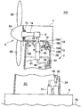
또한, 상기 재생 에너지형 발전 장치는 풍력 발전 장치이며, 상기 타워가 상기 기단부로부터 상기 선단부를 향해서 연직 방향 상방으로 연장하는 동시에, 상기 회전 블레이드에 의해 바람을 받는 것에 의해 상기 주축이 회전하게 되어 있어도 된다. 이 경우, 상기 유압 모터는 그라운드 레벨 가까이에 배치되고 있어도 좋고, 시 레벨 가까이 또는 시 레벨보다도 하방에 배치되어 있어도 된다.The renewable energy type power generation device is a wind power generation device, and the main shaft may be rotated by the tower extending vertically upward from the proximal end toward the distal end and receiving wind by the rotating blade. . In this case, the said hydraulic motor may be arrange | positioned near the ground level, and may be arrange | positioned near the sea level or below the sea level.
또는, 재생 에너지형 발전 장치는 조류, 해류 또는 하류를 이용한 발전 장치이며, 상기 타워가 상기 기단부로부터 상기 선단부를 향해서 해중 또는 수중을 연직 방향 하방으로 연장하는 동시에, 상기 회전 블레이드에 의해 조류, 해류 또는 하류를 받는 것에 의해 상기 주축이 회전하게 되어 있어도 된다.Alternatively, the renewable energy type power generation device is a power generation device using tidal current, current or downstream, wherein the tower extends the sea or the water vertically downward from the base end toward the tip end, and at the same time by the rotating blade, The main shaft may be rotated by receiving downstream.
본 발명에 따르면, 나셀측에 지지된 제 1 이중관을 회전 가능하게 제 2 이중관에 접속했으므로, 나셀이 선회해도, 나셀내의 유압 펌프와 타워 기단부 주변의 유압 모터 사이의 고압유 및 저압유의 교환을 제 1 이중관과 제 2 이중관을 통해서 행할 수 있다.According to the present invention, since the first double pipe supported on the nacelle side is rotatably connected to the second double pipe, even if the nacelle turns, it is possible to replace the high pressure oil and the low pressure oil between the hydraulic pump in the nacelle and the hydraulic motor around the tower base end. This can be done through the first double pipe and the second double pipe.
도 1은 제 1 실시형태에 관한 풍력 발전 장치의 전체 구성예를 나타내는 도면,
도 2는 유압 펌프측의 제 1 이중관의 단부의 상세 구조를 도시하는 단면도,
도 3은 제 1 실시형태에 있어서의, 제 1 이중관과 제 2 이중관의 접합부 주변의 상세 구조를 도시하는 단면도,
도 4는 제 1 이중관과 제 2 이중관의 접속 형태의 도 3과는 다른 예를 나타내는 도면,
도 5는 제 2 실시형태에 관한 풍력 발전 장치의 전체 구성예를 나타내는 도면,
도 6은 제 2 실시형태에 있어서의, 제 1 이중관 및 제 2 이중관의 상세 구조를 도시하는 단면도,
도 7은 제 1 이중관 및 제 2 이중관의 상세 구조의 도 6과는 다른 예를 나타내는 단면도.1 is a diagram showing an example of the entire configuration of a wind turbine generator according to a first embodiment;
2 is a cross-sectional view showing a detailed structure of the end portion of the first double pipe on the hydraulic pump side;
3 is a cross-sectional view showing a detailed structure around the junction of a first double pipe and a second double pipe in the first embodiment;
FIG. 4 is a view showing an example different from FIG. 3 of the connection form of the first double pipe and the second double pipe; FIG.
5 is a diagram showing an example of the entire configuration of a wind turbine generator according to a second embodiment;
6 is a cross-sectional view showing a detailed structure of a first double pipe and a second double pipe in a second embodiment;
7 is a cross-sectional view showing an example different from FIG. 6 of the detailed structure of the first double pipe and the second double pipe.
이하, 첨부 도면을 따라서 본 발명의 실시형태에 대해서 설명한다. 단, 이 실시형태에 기재되어 있는 구성 부품의 치수, 재질, 형상, 그 상대적 배치 등은 특정적인 기재가 없는 한 본 발명의 범위를 이것에 한정하는 취지가 아니고, 단순한 설명 예에 지나지 않는다.EMBODIMENT OF THE INVENTION Hereinafter, embodiment of this invention is described according to an accompanying drawing. However, the dimensions, materials, shapes, relative arrangements, and the like of the component parts described in this embodiment are not intended to limit the scope of the present invention to them unless otherwise specified, and are merely illustrative examples.
[제 1 실시형태][First Embodiment]
제 1 실시형태에서는, 재생 에너지형 발전 장치의 일 예로서 풍력 발전 장치에 대해서 설명한다. 도 1은 제 1 실시형태에 관한 풍력 발전 장치의 전체 구성예를 나타내는 도면이다. 도 2는 유압 펌프측의 제 1 이중관의 단부의 상세 구조를 도시하는 단면도이다. 도 3은 제 1 이중관과 제 2 이중관의 접합부 주변의 상세 구조를 도시하는 단면도이다.In the first embodiment, the wind power generator will be described as an example of the renewable energy type power generator. BRIEF DESCRIPTION OF THE DRAWINGS It is a figure which shows the example of the whole structure of the wind turbine generator which concerns on 1st Embodiment. It is sectional drawing which shows the detailed structure of the edge part of the 1st double pipe by the side of a hydraulic pump. 3 is a cross-sectional view showing the detailed structure around the junction of the first double pipe and the second double pipe.
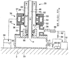
도 1에 도시한 바와 같이, 풍력 발전 장치(1)는, 주로, 타워(2)와, 타워(2) 위에 설치된 나셀(4)과, 바람을 받아서 회전하는 로터(6)와, 유압 펌프(8) 및 유압 모터(10)와, 유압 모터(10)에 연결된 발전기(12)로 구성된다.As shown in FIG. 1, the
타워(2)는, 시 레벨(SL) 부근의 높이에 위치하는 기초(3) 위에 세워 설치되어 있고, 기초(3)측의 기단부(2A)로부터 연직 방향 상방으로 선단부(2B)까지 연장되어 있다. 타워(2)의 선단부(2B) 위에는 나셀(4)이 설치되어 있다. 그리고, 나셀(4)에는, 주축(14) 및 이 주축(14)에 설치된 유압 펌프(8)가 수납되어 있다. 또한, 주축(14)은 주축 베어링(15)에 의해 나셀(4)에 회전 가능하게 지지되어 있다.The
로터(6)는 허브(6A)와, 허브(6A)로부터 방사상으로 연장하는 복수매의 회전 블레이드(6B)로 이루어진다. 로터(6)의 허브(6A)는 주축(14)에 연결되어 있다. 이 때문에, 바람을 받아서 로터(6)가 회전하면, 주축(14)도 허브(6A)와 함께 회전한다. 그리고, 주축(14)의 회전이 유압 펌프(8)에 입력됨으로써, 유압 펌프(8)에 있어서 고압유가 생성된다.The
유압 모터(10)는, 타워(2)의 기단부(2A)에 있어서의 타워 내부 공간(2C)에 설치되고, 기초(3) 위에 설치되어 있다. 유압 모터(10)는 나셀(4) 내의 유압 펌프(8)로부터 공급되는 고압유에 의해 구동된다.The
또한, 유압 모터(10)에 연결되는 발전기(12)도, 유압 모터(10)와 마찬가지로, 타워(2)의 기단부(2A)에 있어서의 타워 내부 공간(2C)에 설치되고, 기초(3) 위에 설치되어 있다.In addition, the
나셀(4)은 나셀 대판(16)을 갖고 있고, 이 나셀 대판(16)은 나셀 베어링(18)에 의해 타워(2)의 선단부(2B)에 선회 가능하게 지지되어 있다. 구체적으로는, 나셀 대판(16)은 나셀 베어링(18)의 내륜(18A)에 고정되고, 타워(2)의 선단부(2B)는 나셀 베어링(18)의 외륜(18B)에 고정되어 있다.The
그리고, 나셀 대판(16)에는 나셀 선회 기구(19)가 설치되어 있고, 이 나셀 선회 기구(19)에 의해, 나셀 대판(16)이 타워(2)의 선단부(2B)에 대하여 선회하게 되어 있다. 또한, 나셀 선회 기구(19)는, 예를 들어 타워(2)의 선단부(2B)의 내주면에 설치된 내치차(19B)와 맞물리는 기어(19A)와, 이 기어(19A)에 직결되어서 기어(19A)를 회전 구동하는 모터로 구성되어 있어도 된다.And the
본 실시형태에서는, 나셀(4)에 수납된 유압 펌프(8)와, 타워(2)의 기단부(2A)에 있어서의 타워 내부 공간(2C)에 설치된 유압 모터(10)를, 제 1 이중관(20) 및 제 2 이중관(30)을 사용해서 접속하고 있다.In this embodiment, the
제 1 이중관(20)은 타워(2)의 대략 전체 길이에 걸쳐서 타워(2)의 선단부(2B)로부터 기단부(2A)까지 하방으로 연장되어 있다. 제 1 이중관(20)은, 도 2 및 도 3에 도시한 바와 같이, 제 1 내측 배관(22) 및 이 제 1 내측 배관(22)의 외주에 설치된 제 1 외측 배관(24)으로 구성된다. 제 1 내측 배관(22)과 제 1 외측 배관(24)은, 나셀(4)측의 단부에 있어서, 용접에 의해 일체화되어 있다(도 2의 용접부(21) 참조). 그리고, 제 1 외측 배관(24)은, 나셀측 지지 기구(26)에 의해, 나셀 대판(16)에 지지되어 있다. 그 때문에, 제 1 외측 배관(24) 및 이것에 용접된 제 1 내측 배관(22)은 나셀(4)의 선회시에, 나셀 대판(16)과 함께 선회하게 되어 있다.The first
또한, 제 1 내측 배관(22)과 제 1 외측 배관(24)의 고정은, 액밀성이 유지가능하면 특별히 한정되지 않고, 용접에 대체해서, 시일 부착 플랜지의 볼트 결합에서 행해도 된다.The first
또한, 제 1 이중관(20)은 제 1 내측 배관(22) 및 제 1 외측 배관(24)의 관 중심이 나셀(4)의 선회 중심과 대략 동일 코어로 되도록 배치되어 있다. 이 때문에, 나셀 대판(16)과 함께 제 1 이중관(20)이 선회해도, 제 1 이중관(20)의 타워(2) 내에 있어서의 위치는 부동이다.Moreover, the 1st double pipe |
또한, 도 1에 도시한 바와 같이, 제 1 이중관(20)의 버클링이나 굴곡 등의 변형을 방지하는 관점으로부터, 타워(2)의 내벽면으로부터 돌출되는 타워측 지지 기구(28)에 의해 제 1 외측 배관(24)을 지지해도 좋다. 타워측 지지 기구(28)는, 예를 들어, 제 1 외측 배관(24)의 외주면에 접촉하는 원환상의 슈(28A)와, 타워(2)의 내벽면으로부터 제 1 외측 배관(24)의 직경 방향 내측으로 돌출되어서 슈(28A)를 지지하는 복수의 지지 바아(28B)로 구성해도 좋다.In addition, as shown in FIG. 1, the tower
이 경우, 슈(28A)의 내주면을 저마찰 재료 또는 슈(28A) 자체를 탄성체 또는 탄성 기구에서 형성하는 등에 의해, 슈(28A) 및 지지 바아(28B)에 의해, 제 1 외측 배관(24)을 회전 가능 또한 길이 방향으로 미끄럼이동 가능하게 지지하는 것이 바람직하다. 이에 의해, 나셀(4)에 수반된 제 1 이중관(20)의 선회를 방해하지 않고, 제 1 이중관(20)의 열 신장을 흡수하면서, 제 1 이중관(20)을 확실하게 지지할 수 있다.In this case, the first
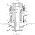
제 2 이중관(30)은, 도 3에 도시한 바와 같이, 제 2 내측 배관(32) 및 제 2 내측 배관(32)의 외주에 설치된 제 2 외측 배관(34)으로 구성된다. 제 2 이중관(30)의 제 2 내측 배관(32)은 저부(33)가 폐쇄된 용기 형상이며, 타워(2)가 세워 설치된 기초(3) 위에 설치되어 있다.As shown in FIG. 3, the 2nd double pipe |
제 2 이중관(30)은 복수의 부재로 구성해도 좋다. 도 3에 도시하는 예에서는, 제 2 이중관(30)의 외형을 만드는 하측 부재(35), 중앙 부재(36) 및 상측 부재(37)와, 중앙 부재(36)에 의해 둘러싸이는 환상 부재(38)로 제 2 이중관(30)이 구성되어 있다. 하측 부재(35)는 저부(33)로 폐쇄된 대용적의 내부 공간을 갖고, 그 측면에는 유압 모터(10)의 흡입측에 접속되는 고압유 출구가 설치되어 있다. 중앙 부재(36)는 하측 부재(35) 위에 설치되고, 그 측면에는 유압 모터(10)의 토출측에 접속되는 저압유 입구가 설치되어 있다. 상측 부재(37)는 중앙 부재(36) 위에 설치되고, 제 1 이중관(20)의 제 1 외측 배관(24)보다도 약간 대경으로 형성되어서 제 1 외측 배관(24)의 하단부 외주를 덮고 있다. 환상 부재(38)는 하측 부재(35) 위에 설치되고, 제 1 이중관(20)의 제 1 내측 배관(22)보다도 약간 대경으로 형성되어서 제 1 내측 배관(22)의 하단부 외주를 덮고 있다.You may comprise the 2nd double pipe |
제 2 이중관(30)에서는, 주로 환상 부재(38)가 제 2 내측 배관(32)을 형성하는 한편, 주로 중앙 부재(36) 및 상측 부재(37)가 제 2 외측 배관(34)을 형성하고 있다.In the second
이와 같은 구성의 제 2 이중관(30)에는, 제 1 이중관(20)이 회전 가능하게 접속되어 있다. 즉, 제 1 이중관(20)의 제 1 내측 배관(22)과 제 2 이중관(30)의 제 2 내측 배관(32) 사이에는 내측 베어링(40)이 설치되고, 이 내측 베어링(40)에 의해 제 1 내측 배관(22)은 제 2 내측 배관(32)에 회전 가능하게 지지되어 있다. 한편, 제 1 이중관(20)의 제 1 외측 배관(24)과 제 2 이중관(30)의 제 2 외측 배관(34) 사이에는 외측 베어링(42)이 설치되고, 이 외측 베어링(42)에 의해 제 1 외측 배관(24)은 제 2 외측 배관(34)에 회전 가능하게 지지되어 있다.The 1st double pipe |
또한, 제 1 이중관(20) 및 제 2 이중관(30)의 열신장(정확하게는 타워(2)와 제 1 이중관(20) 및 제 2 이중관(30)과의 열신장 차)을 흡수하는 관점으로부터, 제 1 이중관(20)을 그 길이 방향으로 미끄럼이동 가능하게 제 2 이중관(30)에 접속하는 것이 바람직하다. 이 경우, 내측 베어링(40)의 외륜을 제 2 내측 배관(32)에 고정하는 동시에, 내측 베어링(40)의 내륜을 제 1 내측 배관(32)에 대하여 관 길이 방향으로 미끄럼이동 가능하게 한다. 마찬가지로, 외측 베어링(42)의 외륜을 제 2 외측 배관(34)에 고정하는 동시에, 외측 베어링(42)의 내륜을 제 1 외측 배관(24)에 대하여 관 길이 방향으로 미끄럼이동 가능하게 한다. 또한, 상정되는 제 1 이중관(20)의 열 신장량의 범위 내에 있어서, 제 1 이중관(20)이 제 2 이중관(30)에 대하여 관 길이 방향으로 미끄럼이동해도, 후술의 내측 유로(44) 및 외측 유로(46)가 막히거나, 각 부의 간섭이 발생하거나 하는 일이 없도록, 제 1 이중관(20) 및 제 2 이중관(30)의 각 부의 치수가 결정되는 것이 바람직하다.In addition, from the viewpoint of absorbing the thermal elongation of the first
또한, 제 1 이중관(20)의 제 2 이중관(30)에 대한 길이 방향의 움직임이 허용되는 결과, 제 1 이중관(20) 및 제 2 이중관(30)을 흐르는 고압유와 저압유에 의해, 제 1 이중관(20)을 나셀(4)측으로 누르는 유압 스러스트(도 3에 있어서의 유압 스러스트 방향을 따른 힘)가 발생한다. 그 때문에, 나셀(4)측에 제 1 이중관(20)을 지지함으로써 증가한, 나셀(4)에서 부담해야 할 하중을 경감할 수 있다. 또한, 그 분량만큼, 타워(2)가 부담해야 할 하중도 경감된다.Further, as a result of allowing the longitudinal movement of the first
이와 같이 하여 접속된 제 1 이중관(20) 및 제 2 이중관(30)에 의해, 유압 펌프(8)로부터 공급되는 고압유가 흐르는 내측 유로(44)와, 유압 모터(10)로부터 배출되는 저압유가 흐르는 외측 유로(46)가 형성된다.The inner
즉, 고압유가 흐르는 내측 유로(44)는, 제 1 이중관(20)의 제 1 내측 배관(22)과 제 2 이중관(30)의 제 2 내측 배관(32)으로 형성된다. 또한, 저압유가 흐르는 외측 유로(46)는, 제 1 이중관(20)의 제 1 외측 배관(24)과 제 2 이중관(30)의 제 2 외측 배관(34)으로 형성된다.In other words, the
이와 같이 내측 유로(44)에 고압유를 흘리고, 외측 유로(46)에 저압유를 흘리는 것으로, 만일 내측 유로(44)의 부식이나 파손 등에 의해 내측 유로(44)의 고압유가 누설되어도, 누설한 고압유를 외측 유로(46)에 받을 수 있다. 따라서, 고압유의 외부에의 누설을 방지할 수 있다.In this way, the high pressure oil flows into the
또한, 제 1 내측 배관(22)의 외벽면과 제 2 내측 배관(32)의 내벽면 사이에는 내측 시일(50)이 설치되어 있다. 이 내측 시일(50)은 내측 유로(44)와 외측 유로(46) 사이에 끼워지도록 배치되어 있다. 즉, 내측 시일(50)은 내측 유로(44)와 외측 유로(46)로 둘러싸여 있다. 이 때문에, 만일 내측 시일(50)의 시일 기능이 손상되어도, 내측 유로(44)를 흐르는 고압유는 외측 유로(46)에 누설된다. 따라서, 고압유의 외부에의 누설을 방지할 수 있다.In addition, an
또한, 제 1 외측 배관(24)의 외벽면과 제 2 외측 배관(34)의 내벽면 사이에는 한쌍의 외측 시일(52)이 설치되어 있다. 그리고, 한쌍의 외측 시일(52)의 사이의 위치에는 연통로(53)를 통해서 오일 저장소(54)가 연통하고 있다. 이 오일 저장소(54)는 대기압 탱크(56)에 접속되어 있다.In addition, a pair of
이에 의해, 만일 외측 시일(52)의 시일 기능이 손상되어도, 외측 유로(46)로부터 누출된 저압유는 연통로(53) 및 오일 저장소(54)를 통해서 대기압 탱크(56)에 유도된다. 즉, 외측 유로(46)로부터 누설된 저압유는 압력이 충분히 낮아지면서 대기압 탱크(56)에 회수된다. 따라서, 저압유의 외부에의 누설을 방지할 수 있다.Thereby, even if the seal function of the
또한, 유압 펌프(8)의 맥동을 억제하는 관점으로부터, 나셀(4) 내에 있어서 유압 펌프(8)와 제 1 이중관(20) 사이에 맥동 방지 어큐뮬레이터를 설치하는 것이 바람직하다. 예를 들어, 도 2에 도시한 바와 같이, 나셀 대판(16) 위에 맥동 방지 어큐뮬레이터(60)를 설치해도 좋다.Moreover, it is preferable to provide a pulsation prevention accumulator between the
이와 같이, 맥동 방지 어큐뮬레이터(60)를 나셀(4) 내에 설치함으로써, 맥동 방지 어큐뮬레이터(60)와 유압 펌프(8)와의 거리가 줄어들고, 유압 펌프(8)의 맥동을 효과적으로 방지할 수 있다. 또한, 맥동 방지 어큐뮬레이터(60)의 용량은 비교적 작아도 좋기 때문에, 나셀(4) 내에 충분히 수납할 수 있다. 특히, 본 실시형태에서는, 유압 모터(10) 및 발전기(12)를 나셀(4)에 설치하는 것이 아니고, 타워(2)의 기단부(2A)의 타워 내부 공간(2C)에 설치하도록 했으므로, 나셀(4) 내에 있어서 맥동 방지 어큐뮬레이터(60)를 위한 설치 스페이스를 충분히 확보할 수 있다.Thus, by providing the
또한, 나셀(4)에 비해 스페이스의 여유가 있는 타워 내부 공간(2C)에는, 도 3에 도시한 바와 같이, 바이패스 유로(62), 릴리프 밸브(64), 오일 쿨러(66) 및 유압 축적 어큐뮬레이터(68)를 설치하는 것이 바람직하다.In addition, as shown in FIG. 3, the
바이패스 유로(62)는 유압 모터(10)를 바이패스하는 유로이며, 제 2 이중관(30)과 유압 모터(10) 사이에 설치된다. 이 바이패스 유로(62)에는 릴리프 밸브(64)가 설치되어 있고, 유압 펌프(8)로부터 유압 모터(10)에 전달되는 고압유의 압력이 상한값을 초과했을 때에 릴리프 밸브(64)가 개방하고, 바이패스 유로(62)를 통해서 고압유가 저압유 유로측에 흐르고, 고압유의 압력을 억제하게 되어 있다. 오일 쿨러(66)는 릴리프 밸브(64)의 하류측(구체적으로는 바이패스 유로(62)와 저압유 유로와의 합류부의 하류측)에 설치되어 있다. 오일 쿨러(66)는 고압유가 릴리프 밸브(64)를 통과할 때에 상승한 유온을 저감하거나, 통상시(릴리프 밸브(64)의 비작동시)에 저압유를 냉각하거나 한다.The
유압 축적 어큐뮬레이터(68)는 맥동 방지 어큐뮬레이터(60)에 비해 충분히 큰 용량을 갖는다. 유압 축적 어큐뮬레이터(68)는, 예를 들어 돌풍이 불었을 때에 과잉한 회전 에너지를 흡수하기 위해서 고압유의 유압을 축적하거나, 계통 전압 저하시의 라이드 스루 기능을 실현하기 위해서 고압유의 유압을 미리 축적해 두거나, 풍력 발전 장치(1)의 출력이 잉여일 때에 과잉한 회전 에너지를 흡수하기 위해서 고압유의 유압을 축적하거나 하는 목적에서 사용된다. 유압 축적 어큐뮬레이터(68)를 타워(2)의 기단부(2A)에 있어서의 타워 내부 공간(2C)에 배치함으로써, 유압 축적 어큐뮬레이터(68)의 용량을 충분히 크게 할 수 있다. 또한, 유압 축적 어큐뮬레이터(68)에의 고압유의 축적은 어큐뮬레이터 밸브(69)를 개폐 제어하는 것으로 행해진다.The
상기 구성의 풍력 발전 장치(1)에 따르면, 나셀(4)측에 지지된 제 1 이중관(20)을 회전 가능하게 제 2 이중관(30)에 접속했으므로, 나셀(4)이 선회해도, 나셀(4) 내의 유압 펌프(8)와 타워(2)의 기단부(2A)에 설치된 유압 모터(10) 사이의 고압유 및 저압유의 교환을 제 1 이중관(20)과 제 2 이중관(30)을 통해서 행할 수 있다.According to the
또한, 도 1 내지 도 3에는 내측 베어링(40) 및 외측 베어링(42)을 사용해서 제 1 이중관(20)을 제 2 이중관(30)에 회전 가능하게 접속하는 예를 나타냈지만, 제 1 이중관(20)과 제 2 이중관(30)과의 접속 형태는 이 예에 한정되지 않고, 내측 베어링(40) 및 외측 베어링(42)을 사용하지 않고 제 1 이중관(20)을 제 2 이중관(30)에 접속해도 좋다.1 to 3 illustrate an example in which the first
도 4는 제 1 이중관(20)과 제 2 이중관(30)과의 접속 형태의 다른 예를 나타내는 도면이다. 도 4에 도시한 바와 같이, 제 1 이중관(20)은 제 2 이중관(30)에 회전 가능하게 끼워춰져도 좋다. 도 4에 도시하는 예에서는, 제 1 내측 배관(22)의 외벽면과 제 2 내측 배관(32)의 내벽면은 회전 방향에 있어서의 상대적인 미끄럼 운동이 허용되도록 미끄럼 접촉하고 있다. 마찬가지로, 제 1 외측 배관(24)의 외벽면과 제 2 외측 배관(34)의 내벽면은 회전 방향에 있어서의 상대적인 미끄럼 운동이 허용되도록 미끄럼 접촉하고 있다.4 is a diagram illustrating another example of a connection form between the first
이때, 제 1 내측 배관(22)이 제 2 내측 배관(32)에 대하여 상대적으로 관 길이 방향으로 미끄럼이동 가능하며, 또한 제 1 외측 배관(24)이 제 2 외측 배관(34)에 대하여 상대적으로 관 길이 방향으로 미끄럼이동 가능하게 하면, 제 1 이중관(20)의 제 2 이중관(30)에 대한 길이 방향의 움직임이 허용된다. 그 결과, 제 1 이중관(20) 및 제 2 이중관(30)의 열 신장(정확하게는 타워(2)와 제 1 이중관(20) 및 제 2 이중관(30)과의 열 신장 차)을 흡수하는 동시에, 제 1 이중관(20)을 나셀(4)측으로 누르는 유압 스러스트(도 4에 있어서의 유압 스러스트 방향을 따른 힘)을 발생시켜서 나셀(4)에서 부담해야 할 하중을 경감할 수 있다. 또한, 그 분량만큼, 타워(2)가 부담해야 할 하중도 경감된다.At this time, the first
여기서, 상정되는 제 1 이중관(20)의 열 신장량의 범위 내에 있어서, 제 1 이중관(20)이 제 2 이중관(30)에 대하여 관 길이 방향으로 미끄럼이동해도, 내측 유로(44) 및 외측 유로(46)가 막히거나, 각 부의 간섭이 발생하거나 하는 일이 없도록, 제 1 이중관(20) 및 제 2 이중관(30)의 각 부의 치수가 결정되는 것이 바람직하다.Here, even if the 1st double pipe |
또한, 도 4에 도시하는 예에서는, 제 2 이중관(30)은 하측 부재(58) 및 상측 부재(59)로 구성되어 있다. 하측 부재(58)는, 그 측면에는 유압 모터(10)의 흡입측에 접속되는 고압유 출구가 설치되고, 그 상부는 제 1 이중관(20)의 제 1 내측 배관(22)보다도 약간 대경의 관 형상으로 이루어져 있고, 제 1 내측 배관(22)의 하단부 외주를 덮고 있다. 상측 부재(59)는, 하측 부재(58) 위에 설치되어 있고, 그 측면에는 유압 모터(10)의 토출측에 접속되는 저압유 입구가 설치되고, 그 상부는 제 1 이중관(20)의 제 1 외측 배관(24)보다도 약간 대경의 관 형상이 이루어져 있고, 제 1 외측 배관(24)의 하단부 외주를 덮고 있다.In addition, in the example shown in FIG. 4, the 2nd double pipe |
또한, 도 3에 도시하는 예와 마찬가지로, 제 1 내측 배관(22)의 외벽면과 제 2 내측 배관(32)의 내벽면 사이에는, 내측 시일(50)이 설치되어 있다. 또한, 제 1 외측 배관(24)의 외벽면과 제 2 외측 배관(34)의 내벽면 사이에는 한쌍의 외측 시일(52)이 설치되어 있고, 한쌍의 외측 시일(52)의 사이의 위치에는 연통로(53)를 통해서 오일 저장소(54)가 연통하고 있다. 이 오일 저장소(54)는 대기압 탱크(56)(도 3 참조)에 접속되어 있다.3, the
또한, 제 2 이중관(30)은 도 1 및 도 3과 같이 기초(3) 위에 적재되고 있어도 좋고, 기초(3)위 또는 타워(2)의 기단부(2A)의 내주면에 지지되어 있어도 된다.In addition, the 2nd double pipe |
[제 2 실시형태] [Second Embodiment]
제 2 실시형태에서는, 제 1 실시형태와는 다른 형태의 풍력 발전 장치에 대해서 설명한다. 도 5는 제 2 실시형태에 관한 풍력 발전 장치의 전체 구성예를 나타내는 도면이다.In 2nd Embodiment, the wind power generator of a form different from 1st Embodiment is demonstrated. 5 is a diagram illustrating an example of the entire configuration of a wind turbine generator according to a second embodiment.
또한, 본 실시형태에 관한 풍력 발전 장치는, 제 1 이중관 및 제 2 이중관의 구성이 다른 점을 제외하면, 제 1 실시형태에 관한 풍력 발전 장치(1)와 마찬가지이다. 따라서, 여기에서는, 제 1 실시형태와 다른 점을 중심으로 설명하는 것으로 하고, 도 5에서는 풍력 발전 장치(1)와 공통되는 개소에는 동일한 도면부호를 부여하고, 그 설명을 생략한다.In addition, the wind power generator which concerns on this embodiment is the same as that of the
본 실시형태에 관한 풍력 발전 장치(100)에서는, 나셀(4) 내의 유압 펌프(8)와 타워(2)의 기단부(2A)의 타워 내부 공간(2C)에 설치된 유압 모터(10) 사이에 제 1 이중관(70) 및 제 2 이중관(80)을 설치하고 있다.In the
제 1 이중관(70)은 타워(2)의 일부만(나셀(4)의 직하만)에 설치되어 있다. 제 1 이중관(70)은 나셀측 지지 기구(26)에 의해 나셀 대판(16)에 지지되어 있고, 나셀(4)의 선회시에 나셀 대판(16)과 함께 선회하도록 되어 있다.The 1st double pipe |
한편, 제 2 이중관(80)은 제 1 이중관(70)의 하방에 설치되어 있고, 타워(2)의 내벽면으로부터 돌출되는 타워측 지지 기구(81)에 의해 리지드에 지지되어 있다. 또한, 제 2 이중관(80)의 유압 모터(10)에의 접속은 고압유가 흐르는 고압유 배관(90)과 저압유가 흐르는 저압유 배관(92)을 통해서 행해진다. 또한, 고압유 배관(90) 및 저압유 배관(92)은 리지드한 파이프로 구성해도 좋고, 플렉시블한 튜브(호스) 또는 회전 방향뿐 고정해서 길이 방향의 열 신장만 흡수하는 벨로우즈와 같은 조인트를 통한 리지드한 파이프로 구성해도 좋다.On the other hand, the 2nd double pipe |
고압유 배관(90) 및 저압유 배관(92)은, 각각, 각 배관의 열 신장을 허용하도록 타워(2)의 내벽면에 지지되어 있다. 예를 들어, 타워(2)의 내벽면에 고정된 원환상의 슈(94)의 내주면을 고압유 배관(90) 및 저압유 배관(92)의 각각의 외주면에 접촉시켜서 지지해도 좋다. 이 경우, 슈(94)의 내주면을 저마찰 재료로 형성하는 등에 의해, 고압유 배관(90) 및 저압유 배관(92)의 각각을 각 슈(94)에 의해 관 길이 방향으로 미끄럼이동 가능하게 지지하면 좋다.The high
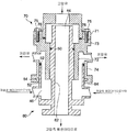
도 6은 제 1 이중관(70) 및 제 2 이중관(80)의 상세 구조를 도시하는 단면도이다. 도 6에 도시한 바와 같이, 제 1 이중관(70)은 플랜지부에 있어서 볼트(75)로 체결된 상측 부재(71) 및 하측 부재(73)에 의해 구성되어 있다. 또한, 상측 부재(71)와 하측 부재(73)와의 접합면에는 시일(76)이 설치되고, 액밀성이 유지되어 있다. 상측 부재(71)는, 그 상부에 있어서 유압 펌프(8)의 토출측에 접속되는 고압유 입구를 갖는다. 하측 부재(73)는 상측 부재(71)에 접합된 플랜지부에서 하방으로 축 늘어지는 내주측 원통부와 외주측 원통부를 갖고, 이 외주측 원통부의 측면에는 유압 펌프(8)의 흡입측에 접속되는 저압유 출구가 설치되어 있다.FIG. 6: is sectional drawing which shows the detailed structure of the 1st double pipe |
그리고, 상측 부재(71)와 하측 부재(73)의 일부(내주측 원통부)에 의해, 제 1 이중관(70)의 제 1 내측 배관(72)이 형성되어 있다. 또한, 하측 부재(73)의 일부(외주측 원통부)에 의해, 제 1 이중관(70)의 제 1 외측 배관(74)이 형성되어 있다.And the 1st
한편, 제 2 이중관(80)은 제 2 내측 배관(82) 및 이 제 2 내측 배관(82)의 외주에 설치되는 제 2 외측 배관(84)을 갖는다. 또한, 제 2 이중관(80)의 하부에는 고압유 배관(90)(도 5 참조)에 접속되는 고압유 출구가 설치되어 있다. 또한, 제 2 이중관(80)의 측면에는, 저압유 배관(92)(도 5 참조)에 접속되는 저압유 입구가 설치되어 있다.On the other hand, the second
그리고, 제 1 이중관(70)은 제 2 이중관(80)에 회전 가능하게 끼워맞춰지고 있다. 즉, 제 1 내측 배관(72)의 내벽면과 제 2 내측 배관(82)의 외벽면은 회전 방향에 있어서의 상대적인 미끄럼 운동이 허용되도록 미끄럼 접촉하고 있다. 마찬가지로, 제 1 외측 배관(74)의 내벽면과 제 2 외측 배관(84)의 외벽면은 회전 방향에 있어서의 상대적인 미끄럼 운동이 허용되도록 미끄럼 접촉하고 있다.The first
이와 같이 끼워맞춰진 제 1 이중관(70) 및 제 2 이중관(80)에 의해, 유압 펌프(8)로부터 공급되는 고압유가 흐르는 내측 유로(44)와, 유압 모터(10)로부터 배출되는 저압유가 흐르는 외측 유로(46)가 형성된다. 내측 유로(44)에 고압유를 흘리고, 외측 유로(46)에 저압유를 흘리는 것에 의해, 고압유의 외부에의 누설을 방지할 수 있다.The inner
또한, 제 1 내측 배관(72)의 내벽면과 제 2 내측 배관(82)의 외벽면 사이에는 내측 시일(50)이 설치되어 있다. 또한, 제 1 외측 배관(74)의 내벽면과 제 2 외측 배관(84) 외벽면 사이에는 한쌍의 외측 시일(52)이 설치되어 있고, 한쌍의 외측 시일(52) 사이의 위치에는 오일 저장소(54)가 설치되어 있다. 이 오일 저장소(54)는 대기압 탱크(56)(도 3 참조)에 접속되어 있다.In addition, an
또한, 제 1 내측 배관(72)의 내벽면과 제 2 내측 배관(82)의 외벽면 사이에는 테이퍼 롤러 베어링(78)이 설치되어 있다. 테이퍼 롤러 베어링(78)은 제 1 이중관(70)이 회전할 수 있도록, 또한 제 1 이중관(70)이 제 2 이중관(80)에 대하여 상대적으로 길이 방향에 움직이지 않도록, 제 1 내측 배관(72)을 제 2 내측 배관(82)에 지지하고 있다. 테이퍼 롤러 베어링(78)은 제 1 이중관(70) 및 제 2 이중관(80)의 길이 방향을 따른 스러스트 하중 및 그들의 직경 방향을 따른 래디얼 하중의 양쪽을 받을 수 있다. 스러스트 하중으로서는, 내측 유로(44) 및 외측 유로(46)를 흐르는 고압유와 저압유에 의해 발생하는 유압 스러스트를 들 수 있다. 또한, 테이퍼 롤러 베어링(78)을 기점으로 해서 제 1 내측 배관(72) 및 제 2 내측 배관(82)이 각각 자유롭게 열 신장되므로, 제 1 내측 배관(72)과 제 2 내측 배관(82)이 오버랩된 부분(끼워맞춤 부분)을 길게 해도, 열 신장에 의한 영향을 받을 일은 없다.In addition, a tapered
상기 구성의 풍력 발전 장치(100)에 따르면, 나셀(4)측에 지지된 제 1 이중관(70)을 회전 가능하게 제 2 이중관(80)에 접속했으므로, 나셀(4)이 선회해도, 나셀(4) 내의 유압 펌프(8)와 타워(2)의 기단부(2A)에 설치된 유압 모터(10) 사이의 고압유 및 저압유의 교환을 제 1 이중관(70)과 제 2 이중관(80)을 통해서 행할 수 있다.According to the
또한, 도 5에는 제 1 이중관(70)이 나셀(4)의 직하만에 설치된 예를 나타냈지만, 제 1 이중관(70)은 나셀(4)측으로부터 타워(2) 내의 임의의 위치까지 연장하도록 해도 좋다.In addition, although the 1st double pipe |
또한, 도 6에는 제 1 내측 배관(72)의 내벽면과 제 2 내측 배관(82)의 외벽면 사이에 테이퍼 롤러 베어링(78)을 설치하는 예를 설명했지만, 테이퍼 롤러 베어링(78)은 생략해도 좋다.In addition, although the example in which the
도 7은 제 1 이중관(70) 및 제 2 이중관(80)의 상세 구조 외에의 예를 나타내는 단면도이다. 도 7에 도시하는 예에서는, 제 1 이중관(70)은, 제 2 이중관(80)에 대하여 상대적으로 길이 방향으로 미끄럼이동할 수 있도록, 제 2 이중관(80)에 회전 가능하게 끼워맞춰지고 있다. 즉, 제 1 내측 배관(72)이 제 2 내측 배관(82)에 대하여 상대적으로 관 길이 방향으로 미끄럼이동 가능하며, 또한 제 1 외측 배관(74)이 제 2 외측 배관(84)에 대하여 상대적으로 관 길이 방향으로 미끄럼이동 가능하게 이루어지고 있다. 이와 같이, 제 1 이중관(70)의 제 2 이중관(80)에 대한 길이 방향의 움직임을 허용함으로써, 제 1 이중관(70) 및 제 2 이중관(80)의 열 신장을 흡수하는 동시에, 제 1 이중관(80)을 나셀(4)측으로 누르는 유압 스러스트를 발생시켜서, 나셀(4)이 부담해야 할 하중을 경감할 수 있다.FIG. 7: is sectional drawing which shows the example other than the detailed structure of the 1st double pipe |
또한, 상정되는 제 1 이중관(70) 및 제 2 이중관(80)의 열 신장량의 범위 내에 있어서, 제 1 이중관(70)이 제 2 이중관(80)에 대하여 관 길이 방향으로 미끄럼이동해도, 내측 유로(44) 및 외측 유로(46)가 막히거나, 각 부의 간섭이 발생하거나 하는 일이 없도록, 제 1 이중관(70) 및 제 2 이중관(80)의 각 부의 치수가 결정되는 것이 바람직하다.In addition, even if the 1st double pipe |
이상, 본 발명의 실시형태에 대해서 상세하게 설명했지만, 본 발명은 이것에 한정되지 않고, 본 발명의 요지를 일탈하지 않는 범위에 있어서, 각종 개량이나 변형을 행해도 좋은 것은 말할 필요도 없다.As mentioned above, although embodiment of this invention was described in detail, this invention is not limited to this, Needless to say that various improvement and deformation may be performed in the range which does not deviate from the summary of this invention.
특히, 상술한 실시형태에서는, 시 레벨(SL) 부근의 기초(3) 위에 유압 모터(10)를 설치하는 예에 대해서 설명했지만, 유압 모터(10)는, 타워 기단부의 주변이면, 그라운드 레벨 부근에 설치해도 좋고, 부체식 해상 풍력 발전 장치에 있어서의 시 레벨(SL)보다도 하방의 타워 하부(타워 중 해중에 가라앉은 부분)에 설치해도 좋다. 여기서, 타워 기단부의 주변은 타워의 외부의 장소도 포함하는 의미이다.In particular, in the above-described embodiment, an example in which the
또한, 상술한 실시형태에서는, 재생 에너지형 발전 장치의 구체예로서 풍력 발전 장치(1 및 100)에 대해서 설명했지만, 본 발명은 풍력 발전 장치 이외의 재생 에너지형 발전 장치에도 적용할 수 있다.In addition, although the above-mentioned embodiment demonstrated the
예를 들어, 조류, 해류 또는 하류를 이용한 발전 장치이며, 타워가 기단부로부터 선단부를 향해서 해중 또는 수중을 연직 방향 하방으로 연장하는 동시에, 회전 블레이드에 의해 조류, 해류 또는 하류를 받는 것에 의해 주축이 회전하는 것과 같은 발전 장치에 본 발명을 적용해도 좋다.For example, a power generation device using tidal currents, currents, or downstream, wherein the tower is rotated by receiving a tidal current, current or downstream by a rotary blade while extending the sea or water vertically downward from the proximal end toward the distal end. The present invention may be applied to such a power generator as described above.
1 : 풍력 발전 장치 2 : 타워
4 : 나셀 6 : 로터
6A : 허브 6B : 회전 블레이드
8 : 유압 펌프 10 : 유압 모터
12 : 발전기 14 : 주축
15 : 주축 베어링 16 : 나셀 대판
18 : 나셀 베어링 18A: 내륜
18B : 외륜 19 : 나셀 선회 기구
19A : 기어 19B : 내치차
20 : 제 1 이중관 21 : 용접부
22 : 제 1 내측 배관 24 : 제 2 내측 배관
26 : 나셀측 지지 기구 28 : 타워측 지지 기구
28A : 슈 28B : 지지 바아
30 : 제 2 이중관 32 : 제 2 내측 배관
34 : 제 2 외측 배관 35 : 하측 부재
36 : 중앙 부재 37 : 상측 부재
38 : 환상 부재 40 : 내측 베어링
42 : 외측 베어링 44 : 내측 유로
46 : 외측 유로 50 : 내측 시일
52 : 외측 시일 53 : 연통로
54 : 오일 저장소 56 : 대기압 탱크
60 : 맥동 방지 어큐뮬레이터 62 : 바이패스 유로
64 : 릴리프 밸브 66 : 오일 쿨러
68 : 유압 축적 어큐뮬레이터 69 : 어큐뮬레이터 밸브
70 : 제 1 이중관 71 : 상측 부재
72 : 제 1 내측 배관 73 : 하측 부재
74 : 제 1 외측 배관 75 : 볼트
76 : 시일 80 : 제 2 이중관
81 : 타워측 지지 기구 82 : 제 2 내측 배관
84 : 제 2 외측 배관 90 : 고압유 배관
92 : 저압유 배관 94 : 슈1: wind power generator 2: tower
4: nacelle 6: rotor
6A:
8: hydraulic pump 10: hydraulic motor
12: generator 14: spindle
15: spindle bearing 16: nacelle plate
18: nacelle bearing 18A: inner ring
18B: paddle wheel 19: nacelle turning mechanism
19A:
20: first double pipe 21: weld
22: first inner pipe 24: second inner pipe
26 nacelle
28A:
30: second double pipe 32: second inner pipe
34: second outer pipe 35: lower member
36: center member 37: upper member
38: annular member 40: inner bearing
42: outer bearing 44: inner channel
46: outer passage 50: inner seal
52: outer seal 53: communication path
54: oil reservoir 56: atmospheric pressure tank
60: pulsation prevention accumulator 62: bypass flow path
64: relief valve 66: oil cooler
68: Hydraulic Accumulation Accumulator 69: Accumulator Valve
70: first double pipe 71: upper member
72: first inner pipe 73: lower member
74: first outer pipe 75: bolt
76: seal 80: second double pipe
81: tower side support mechanism 82: second inner pipe
84: second outer pipe 90: high pressure oil pipe
92: low pressure oil pipe 94: shoe
Claims (20)
상기 타워의 선단부에 설치된 나셀과,
상기 나셀에 수납되어, 회전 블레이드와 함께 회전하는 주축과,
상기 나셀에 수납되어, 상기 주축에 설치되는 유압 펌프와,
상기 타워의 기단부 주변에 배치되고, 상기 유압 펌프로부터 공급되는 압유에 의해 구동되는 유압 모터와,
상기 유압 모터에 연결된 발전기와,
상기 유압 펌프에 접속되는 제 1 내측 배관 및 제 1 외측 배관을 갖고, 상기 나셀측에 지지되는 동시에 상기 타워 내부를 통과해서 상기 타워의 기단부에 향해서 연장하는 제 1 이중관과,
상기 유압 모터에 접속되는 제 2 내측 배관 및 제 2 외측 배관을 갖고, 상기 제 1 이중관보다도 상기 나셀로부터 먼 측에 위치해서 상기 제 1 이중관에 끼워맞춰지는 제 2 이중관을 포함하고,
상기 제 1 내측 배관은 상기 제 2 내측 배관에 연통하고, 상기 제 2 내측 배관과 함께 내측 유로를 형성하고,
상기 제 1 외측 배관은 상기 제 2 외측 배관에 연통하고, 상기 제 2 외측 배관과 함께 외측 유로를 형성하고,
상기 내측 유로 및 상기 외측 유로의 어느 한쪽에는, 상기 유압 펌프로부터 토출되어서 상기 유압 모터에 보내지는 고압유가 흐르고,
상기 내측 유로 및 상기 외측 유로의 다른 쪽에는 상기 유압 모터로부터 배출되어서 상기 유압 펌프에 복귀되는 저압유가 흐르고,
상기 나셀측에 지지된 상기 제 1 이중관은 회전 가능하게 상기 제 2 이중관에 접속되어 있는 것을 특징으로 하는
재생 에너지형 발전 장치.With towers,
A nacelle installed at the tip of the tower;
A main shaft accommodated in the nacelle and rotating together with a rotating blade;
A hydraulic pump stored in the nacelle and installed on the main shaft;
A hydraulic motor disposed around the proximal end of the tower and driven by pressure oil supplied from the hydraulic pump;
A generator connected to the hydraulic motor,
A first double pipe having a first inner pipe and a first outer pipe connected to the hydraulic pump, supported on the nacelle side, and extending through the tower interior toward the base end of the tower;
A second double pipe having a second inner pipe connected to the hydraulic motor and a second outer pipe, the second double pipe being positioned farther from the nacelle than the first double pipe and fitted into the first double pipe;
The first inner pipe communicates with the second inner pipe, forms an inner flow path together with the second inner pipe,
The first outer pipe communicates with the second outer pipe, and forms an outer flow path together with the second outer pipe,
High pressure oil discharged from the hydraulic pump and sent to the hydraulic motor flows in either of the inner flow passage and the outer flow passage,
Low pressure oil flowing from the hydraulic motor and returned to the hydraulic pump flows to the other side of the inner flow passage and the outer flow passage,
The first double pipe supported on the nacelle side is rotatably connected to the second double pipe.
Renewable energy type generator.
상기 제 1 이중관은, 상기 나셀에 가까운 측의 단부에 있어서, 상기 제 1 내측 배관과 상기 제 1 외측 배관이 결합되어서 일체화되어 있는 것을 특징으로 하는
재생 에너지형 발전 장치.The method of claim 1,
The first double pipe is integrally formed by joining the first inner pipe and the first outer pipe at an end portion close to the nacelle.
Renewable energy type generator.
상기 내측 유로에는 상기 고압유가 흐르고, 상기 외측 유로에는 상기 저압유가 흐르는 것을 특징으로 하는
재생 에너지형 발전 장치.The method of claim 1,
The high pressure oil flows in the inner flow passage, and the low pressure oil flows in the outer flow passage.
Renewable energy type generator.
상기 제 1 내측 배관의 관 벽면과 상기 제 2 내측 배관의 관 벽면 사이를 시일하는 내측 시일을 더 구비하고,
상기 내측 시일은 상기 내측 유로와 상기 외측 유로 사이에 끼워지도록 배치되어 있는 것을 특징으로 하는
재생 에너지형 발전 장치.The method of claim 3, wherein
And an inner seal for sealing between the pipe wall surface of the first inner pipe and the pipe wall surface of the second inner pipe,
The inner seal is disposed so as to be sandwiched between the inner passage and the outer passage.
Renewable energy type generator.
상기 제 1 외측 배관의 관 벽면과 상기 제 2 외측 배관의 관 벽면 사이를 시일하는 한쌍의 외측 시일과,
상기 한쌍의 외측 시일 사이에 연통하는 오일 저장소와,
상기 오일 저장소에 연통하는 탱크를 더 구비하는 것을 특징으로 하는
재생 에너지형 발전 장치.The method of claim 3, wherein
A pair of outer seals sealing between the pipe wall surface of the first outer pipe and the pipe wall surface of the second outer pipe;
An oil reservoir in communication between the pair of outer seals,
And further comprising a tank in communication with said oil reservoir.
Renewable energy type generator.
상기 제 1 이중관은, 상기 타워의 대략 전체 길이에 걸쳐서, 상기 나셀측으로부터 상기 타워의 기단부까지 연장되어 있고,
상기 제 2 이중관은 상기 타워의 기단부 주변에 지지되는 것을 특징으로 하는
재생 에너지형 발전 장치.The method of claim 1,
The first double pipe extends from the nacelle side to the proximal end of the tower over approximately the entire length of the tower,
The second double pipe is supported around the proximal end of the tower
Renewable energy type generator.
상기 제 2 이중관은 저부가 폐쇄된 용기 형상이며, 상기 타워가 세워 설치되는 기초 위에 설치되어 있는 것을 특징으로 하는
재생 에너지형 발전 장치.The method according to claim 6,
The second double pipe has a bottom shape of a closed container, and is installed on a foundation on which the tower is installed.
Renewable energy type generator.
상기 제 1 이중관은 상기 제 2 이중관에 회전 가능하게 끼워맞춰져 있고,
상기 제 1 내측 배관 및 상기 제 2 내측 배관이 길이 방향으로 상대적으로 미끄럼이동 가능, 또한 상기 제 1 외측 배관 및 상기 제 2 외측 배관이 길이 방향으로 상대적으로 미끄럼이동 가능한 것을 특징으로 하는
재생 에너지형 발전 장치.The method according to claim 6,
The first double pipe is rotatably fitted to the second double pipe,
The first inner pipe and the second inner pipe are relatively slidable in the longitudinal direction, and the first outer pipe and the second outer pipe are relatively slidable in the longitudinal direction.
Renewable energy type generator.
상기 타워의 내주면에 고정되어, 상기 제 1 이중관의 상기 제 1 외측 배관의 외주면에 상기 제 1 외측 배관의 직경 방향 외측으로부터 접촉하는 지지 수단을 더 구비하고,
상기 지지 수단은 상기 제 1 이중관을 회전 가능 또한 길이 방향으로 미끄럼이동 가능하게 지지하는 것을 특징으로 하는
재생 에너지형 발전 장치.The method according to claim 6,
It is fixed to the inner peripheral surface of the tower, and further provided with support means for contacting the outer peripheral surface of the first outer pipe of the first double pipe from the radially outer side of the first outer pipe,
The support means is characterized in that for supporting the first double pipe rotatably and sliding in the longitudinal direction
Renewable energy type generator.
상기 제 1 내측 배관 및 상기 제 2 내측 배관 사이에 설치되고, 상기 제 1 내측 배관을 회전 가능하게 상기 제 2 내측 배관에 지지하는 내측 베어링과,
상기 제 1 외측 배관 및 상기 제 2 외측 배관 사이에 설치되고, 상기 제 1 외측 배관을 회전 가능하게 상기 제 2 외측 배관에 지지하는 외측 베어링을 더 구비하고,
상기 내측 베어링은 상기 제 1 내측 배관에 대하여 그 길이 방향으로 미끄럼이동 가능하며,
상기 외측 베어링은 상기 제 1 외측 배관에 대하여 그 길이 방향으로 미끄럼이동 가능한 것을 특징으로 하는
재생 에너지형 발전 장치.The method according to claim 6,
An inner bearing provided between the first inner pipe and the second inner pipe, the inner bearing supporting the first inner pipe to the second inner pipe so as to be rotatable;
An outer bearing provided between the first outer pipe and the second outer pipe, the outer bearing supporting the first outer pipe to the second outer pipe so as to be rotatable;
The inner bearing is slidable in the longitudinal direction with respect to the first inner pipe,
The outer bearing is slidable in the longitudinal direction with respect to the first outer pipe, characterized in that
Renewable energy type generator.
상기 제 1 이중관은 상기 나셀측으로부터 상기 타워의 도중까지 연장되어 있고,
상기 제 2 이중관은 상기 타워에 지지되어 있는 것을 특징으로 하는
재생 에너지형 발전 장치.The method of claim 1,
The first double pipe extends from the nacelle side to the middle of the tower,
The second double pipe is supported on the tower
Renewable energy type generator.
상기 제 1 이중관을 상기 제 2 이중관에 회전 가능하게 지지하고, 상기 제 1 이중관 및 상기 제 2 이중관의 길이 방향을 따른 스러스트 하중을 받는 스러스트 베어링을 더 구비하는 것을 특징으로 하는
재생 에너지형 발전 장치.The method of claim 11,
And a thrust bearing rotatably supporting the first double pipe to the second double pipe and receiving a thrust load along the longitudinal direction of the first double pipe and the second double pipe.
Renewable energy type generator.
상기 스러스트 베어링은, 상기 스러스트 하중에 추가해서, 직경 방향을 따른 래디얼 하중도 받는 테이퍼 롤러 베어링인 것을 특징으로 하는
재생 에너지형 발전 장치.13. The method of claim 12,
The thrust bearing is a tapered roller bearing that also receives a radial load along the radial direction in addition to the thrust load.
Renewable energy type generator.
상기 제 1 이중관과 상기 제 2 이중관은 상기 제 1 내측 배관 및 상기 제 2 내측 배관이 길이 방향으로 상대적으로 미끄럼이동 가능, 또한 상기 제 1 외측 배관 및 상기 제 2 외측 배관이 길이 방향으로 상대적으로 미끄럼이동 가능하게 되도록 끼워맞춰져 있는 것을 특징으로 하는
재생 에너지형 발전 장치.The method of claim 11,
The first double pipe and the second double pipe are relatively slidable in the longitudinal direction of the first inner pipe and the second inner pipe, and the first outer pipe and the second outer pipe are relatively slip in the longitudinal direction. It is fitted so that it is movable
Renewable energy type generator.
상기 나셀 내에 있어서 상기 유압 펌프와 상기 제 1 이중관 사이에 설치되고, 상기 유압 펌프의 맥동을 방지하는 맥동 방지 어큐뮬레이터를 더 구비하는 것을 특징으로 하는
재생 에너지형 발전 장치.The method of claim 1,
A pulsation preventing accumulator is provided between the hydraulic pump and the first double pipe in the nacelle and prevents pulsation of the hydraulic pump.
Renewable energy type generator.
상기 제 2 이중관과 상기 유압 모터의 사이에 설치되고, 상기 유압 모터를 바이패스하는 바이패스 유로와,
상기 타워의 기단부 주변에 배치되고, 상기 바이패스 유로에 설치된 릴리프 밸브와,
상기 타워의 기단부 주변에 설치되고, 상기 릴리프 밸브의 하류측에 설치된 오일 쿨러를 더 구비하는 것을 특징으로 하는
재생 에너지형 발전 장치.The method of claim 1,
A bypass flow passage provided between the second double pipe and the hydraulic motor and bypassing the hydraulic motor;
A relief valve disposed around the base end of the tower and installed in the bypass flow path;
It is provided around the base end of the tower, characterized in that it further comprises an oil cooler installed on the downstream side of the relief valve
Renewable energy type generator.
상기 타워의 기단부 주변에 배치되고, 상기 고압유의 유압을 축적하는 유압 축적 어큐뮬레이터를 더 구비하는 것을 특징으로 하는
재생 에너지형 발전 장치.The method of claim 1,
It is disposed around the base end of the tower, characterized in that it further comprises a hydraulic accumulator accumulating the hydraulic pressure of the high pressure oil
Renewable energy type generator.
상기 재생 에너지형 발전 장치는 풍력 발전 장치이며,
상기 타워가 상기 기단부로부터 상기 선단부를 향해서 연직 방향 상방으로 연장하는 동시에,
상기 회전 블레이드에 의해 바람을 받는 것에 의해 상기 주축이 회전하는
재생 에너지형 발전 장치.The method of claim 1,
The renewable energy type power generation device is a wind power generation device,
The tower extends vertically upward from the proximal end toward the distal end;
The main shaft rotates by being winded by the rotating blade
Renewable energy type generator.
상기 유압 모터는 그라운드 레벨 가까이에 배치되는 것을 특징으로 하는
재생 에너지형 발전 장치.The method of claim 18,
The hydraulic motor is arranged near the ground level.
Renewable energy type generator.
상기 유압 모터는 시 레벨(sea level) 가까이 또는 시 레벨보다도 하방에 배치되는 것을 특징으로 하는
재생 에너지형 발전 장치.The method of claim 18,
The hydraulic motor is disposed near or below the sea level.
Renewable energy type generator.
Applications Claiming Priority (1)
| Application Number | Priority Date | Filing Date | Title |
|---|---|---|---|
| PCT/JP2011/058647 WO2012137311A1 (en) | 2011-04-05 | 2011-04-05 | Renewable energy generator device |
Publications (1)
| Publication Number | Publication Date |
|---|---|
| KR20120139667A true KR20120139667A (en) | 2012-12-27 |
Family
ID=45806877
Family Applications (2)
| Application Number | Title | Priority Date | Filing Date |
|---|---|---|---|
| KR1020127010770A KR20120139667A (en) | 2011-04-05 | 2011-04-05 | Renewable energy type generating apparatus |
| KR1020127034038A KR101296054B1 (en) | 2011-04-05 | 2011-09-22 | Renewable energy generator |
Family Applications After (1)
| Application Number | Title | Priority Date | Filing Date |
|---|---|---|---|
| KR1020127034038A KR101296054B1 (en) | 2011-04-05 | 2011-09-22 | Renewable energy generator |
Country Status (8)
| Country | Link |
|---|---|
| US (2) | US8403644B2 (en) |
| EP (2) | EP2530307A4 (en) |
| JP (1) | JP4950368B1 (en) |
| KR (2) | KR20120139667A (en) |
| CN (2) | CN102822513A (en) |
| AU (1) | AU2011310936A1 (en) |
| IN (1) | IN2012DN03058A (en) |
| WO (2) | WO2012137311A1 (en) |
Cited By (1)
| Publication number | Priority date | Publication date | Assignee | Title |
|---|---|---|---|---|
| WO2016006965A1 (en) * | 2014-07-10 | 2016-01-14 | 송길봉 | Bearing apparatus and power generating apparatus including same |
Families Citing this family (20)
| Publication number | Priority date | Publication date | Assignee | Title |
|---|---|---|---|---|
| US8541897B2 (en) * | 2009-09-01 | 2013-09-24 | University Of Southern California | Generation of electric energy using cable-supported windmills |
| US20130028729A1 (en) * | 2011-07-28 | 2013-01-31 | Jones Jack A | Power generation systems and methods |
| EP2896825B1 (en) * | 2012-12-19 | 2018-10-31 | Mitsubishi Heavy Industries, Ltd. | Renewable energy power generation device |
| US8777555B1 (en) * | 2013-02-21 | 2014-07-15 | Lockheed Martin Corporation | Yaw drive tidal turbine system and method |
| JP6125910B2 (en) * | 2013-05-31 | 2017-05-10 | 株式会社日立製作所 | Wind power generation equipment |
| GB2515298B (en) * | 2013-06-18 | 2015-06-17 | Tidal Generation Ltd | Water current power generation structure |
| JP6448114B2 (en) * | 2013-07-23 | 2019-01-09 | 大洋プラント株式会社 | Wind energy equipment |
| US9885340B2 (en) * | 2015-01-26 | 2018-02-06 | Patrick Kenneth Powell | Aerodynamic screen system |
| WO2016135800A1 (en) * | 2015-02-23 | 2016-09-01 | 株式会社日立製作所 | Power generation system |
| EP3096007A1 (en) * | 2015-05-21 | 2016-11-23 | Rotation Consultancy & Science Publications | A wind turbine |
| US20170074248A1 (en) * | 2015-09-10 | 2017-03-16 | Ben M. Enis | Wind turbine station and tower with vertical storage tanks |
| US9845792B2 (en) * | 2015-10-13 | 2017-12-19 | Huseyin Ozcan | Wind turbine system |
| WO2017106530A1 (en) * | 2015-12-16 | 2017-06-22 | Daniel Khalitov | Air jet device and method |
| CN106121928A (en) * | 2016-07-25 | 2016-11-16 | 燕山大学 | A kind of hydraulic stormy waves complemental power-generation unit |
| JP6363148B2 (en) | 2016-11-04 | 2018-07-25 | 三菱重工業株式会社 | Renewable energy generator |
| CN106640527A (en) * | 2016-12-12 | 2017-05-10 | 江苏金风科技有限公司 | Hydraulic control system and wind power generating set |
| DE102017004800A1 (en) * | 2017-05-18 | 2018-11-22 | Senvion Gmbh | A nacelle component for a wind turbine and method for mounting a nacelle component |
| CN109667721B (en) * | 2019-01-02 | 2021-01-29 | 武汉船用机械有限责任公司 | Tower drum unit erecting tool |
| CN110360057B (en) * | 2019-07-30 | 2020-11-13 | 上海电气风电集团股份有限公司 | Single-blade hoisting barring device of wind generating set and hoisting method thereof |
| FR3109804B1 (en) * | 2020-05-01 | 2023-07-14 | Roux Jean Francois | OFFSHORE WIND TURBINE FIXED ON A SUBMERSIBLE BOAT POWERING THREE ELECTRIC GENERATORS LOCATED IN THE CENTRAL HULL. |
Family Cites Families (60)
| Publication number | Priority date | Publication date | Assignee | Title |
|---|---|---|---|---|
| IT527036A (en) * | 1950-04-24 | |||
| US2706255A (en) * | 1954-01-18 | 1955-04-12 | Garrett Corp | Electric power generating and air cooling system |
| US3030118A (en) * | 1958-05-13 | 1962-04-17 | Cocker Machine & Foundry Compa | Seal for a rotating shaft |
| US3547556A (en) * | 1968-12-23 | 1970-12-15 | Herman P Smith | Hydraulically driven wind machine |
| US3943717A (en) * | 1974-01-07 | 1976-03-16 | Caterpillar Tractor Co. | Contaminant removal from a hydraulic cylinder |
| US4280061A (en) | 1978-10-25 | 1981-07-21 | Sir Henry Lawson-Tancred, Sons & Co. Ltd. | Method and apparatus for generating electricity from a fixed pitch wind wheel |
| JPS5928136Y2 (en) * | 1979-08-30 | 1984-08-14 | 株式会社島津製作所 | Wind energy conversion device |
| JPS61212674A (en) * | 1985-03-19 | 1986-09-20 | Matsushita Seiko Co Ltd | Power transmitting apparatus of windmill |
| JPS6220678A (en) * | 1985-07-19 | 1987-01-29 | Matsushita Seiko Co Ltd | Warming apparatus utilizing wind power |
| JPH04181041A (en) * | 1990-11-16 | 1992-06-29 | Toyota Motor Corp | Vibration reduction device for vehicle |
| DK9500262U4 (en) | 1995-07-07 | 1996-10-07 | Bonus Energy As | Bottom frame for wind turbine housing and wind turbine comprising the same |
| DE19814629A1 (en) | 1998-03-26 | 1999-09-30 | Tacke Windenergie Gmbh | Arrangement for the rotatable mounting of the machine nacelle of a wind turbine |
| JP2975923B1 (en) * | 1998-05-22 | 1999-11-10 | 日本ピラー工業株式会社 | Rotary joint device |
| JP2002213842A (en) | 2001-01-17 | 2002-07-31 | Calsonic Kansei Corp | Double-pipe connection structure of with respect to expansion valve and the expansion valve |
| DE10229390A1 (en) * | 2001-09-25 | 2003-04-24 | Thomas Nikolaus | Wind power machine has wind-powered rotor element driving hydraulic pumps either directly or indirectly, e.g. connected to rotor by regulator depending on rotor element power |
| BR0207714B1 (en) * | 2001-12-28 | 2011-05-17 | wind turbine and method of operation. | |
| AU2003229454A1 (en) * | 2002-05-16 | 2003-12-02 | Mlh Global Corporation Inc. | Wind turbine with hydraulic transmission |
| DE502005007967D1 (en) | 2004-02-18 | 2009-10-08 | Franz Mitsch | |
| JP2005248738A (en) | 2004-03-02 | 2005-09-15 | Fuchu Giken:Kk | Operation control method for wind power generator |
| EP1637733A1 (en) * | 2004-09-17 | 2006-03-22 | Elsam A/S | A power plant, a windmill, and a method of producing electrical power from wind energy |
| ES2315042B1 (en) | 2004-12-15 | 2010-01-11 | GAMESA INNOVATION & TECHNOLOGY, S.L. | SYSTEM OF WITHDRAWAL OF THE CAPOTA OF AN AEROGENERATOR. |
| ES2264625B1 (en) | 2004-12-15 | 2007-12-01 | GAMESA INNOVATION & TECHNOLOGY, S.L. | REMOVAL PROCEDURE FROM THE COVER OF AN AIRBRUSHER. |
| US7183664B2 (en) | 2005-07-27 | 2007-02-27 | Mcclintic Frank | Methods and apparatus for advanced wind turbine design |
| US7863767B2 (en) * | 2005-10-31 | 2011-01-04 | Chapdrive As | Turbine driven electric power production system and a method for control thereof |
| NO323807B1 (en) * | 2005-10-31 | 2007-07-09 | Chapdrive As | Hydraulic transmission method and system |
| JP3118509U (en) | 2005-11-11 | 2006-01-26 | 興國機工株式会社 | Twin swivel joint structure |
| US20080047271A1 (en) * | 2006-05-19 | 2008-02-28 | General Compression, Inc. | Wind turbine system |
| US7569943B2 (en) | 2006-11-21 | 2009-08-04 | Parker-Hannifin Corporation | Variable speed wind turbine drive and control system |
| US7615884B2 (en) * | 2007-01-30 | 2009-11-10 | Mcmastercorp, Inc. | Hybrid wind turbine system, apparatus and method |
| WO2008113699A2 (en) * | 2007-03-21 | 2008-09-25 | Rle-International Gmbh | Energy conversion device with hydraulic drive |
| US7656055B2 (en) | 2007-04-12 | 2010-02-02 | Rosalia Torres | Hydro-wind power generating turbine system and retrofitting method |
| DK2003362T3 (en) | 2007-06-14 | 2018-01-15 | Fm Energie Gmbh & Co Kg | Hydraulically biased elastomeric spring element and its use in bearings for wind turbines |
| CN101766000A (en) | 2007-06-26 | 2010-06-30 | 传媒专利有限公司 | The method and apparatus of managing multicast group |
| KR100832053B1 (en) * | 2007-08-21 | 2008-05-27 | 김동용 | The wind turbine system by controlled fluid torque converter set |
| NO327277B1 (en) * | 2007-10-30 | 2009-06-02 | Chapdrive As | Wind turbine with hydraulic swivel |
| NO327276B1 (en) * | 2007-11-08 | 2009-06-02 | Chapdrive As | Wind turbine with electric swivel |
| NO327275B1 (en) * | 2007-11-13 | 2009-06-02 | Chapdrive As | Wind turbine with rotating hydrostatic transmission system |
| JP4796039B2 (en) * | 2007-11-22 | 2011-10-19 | 三菱重工業株式会社 | Wind power generator |
| WO2009076757A2 (en) * | 2007-12-14 | 2009-06-25 | David Mcconnell | Wind to electric energy conversion with hydraulic storage |
| JP2009162305A (en) | 2008-01-07 | 2009-07-23 | Tgk Co Ltd | Flexible hose |
| DE102008013728A1 (en) | 2008-03-11 | 2009-09-17 | Kenersys Gmbh | Wind energy plant for generating electrical energy |
| DK2300709T3 (en) | 2008-04-30 | 2016-02-29 | Multibrid Gmbh | Coating of a gondola to a wind power installation |
| CA2668995C (en) * | 2008-06-11 | 2012-01-24 | Mitsubishi Heavy Industries, Ltd. | Wind turbine generator |
| US20100032959A1 (en) | 2008-08-08 | 2010-02-11 | General Electric Company | Wind turbine system |
| GB2463647B (en) | 2008-09-17 | 2012-03-14 | Chapdrive As | Turbine speed stabillisation control system |
| US8882355B2 (en) | 2008-12-15 | 2014-11-11 | Jochen Corts | Segmented composite bearings and wind generator utilizing hydraulic pump/motor combination |
| US8021101B2 (en) | 2008-12-15 | 2011-09-20 | General Electric Company | Wind turbine and method of assembling the same |
| WO2010102636A2 (en) | 2009-03-13 | 2010-09-16 | Vestas Wind Systems A/S | Height adjustable wind turbine nacelle |
| ES2674725T3 (en) | 2009-03-13 | 2018-07-03 | Vestas Wind Systems A/S | Wind turbine gondola |
| US7763989B2 (en) | 2009-07-07 | 2010-07-27 | General Electric Company | Method and apparatus for controlling the tip speed of a blade of a wind turbine |
| CN102648346B (en) | 2009-10-27 | 2015-03-18 | 维斯塔斯风力系统集团公司 | A wind turbine and a mounting method thereof |
| EP2317137B1 (en) | 2009-11-02 | 2012-07-25 | General Electric Company | Configuration of a wind turbine nacelle |
| US8591186B2 (en) | 2009-11-17 | 2013-11-26 | Vestas Wind Systems A/S | Nacelle for wind turbine |
| EP2529112B1 (en) | 2010-02-23 | 2015-08-19 | Artemis Intelligent Power Limited | Variable displacement radial piston fluid working machine |
| US20130011272A1 (en) | 2010-03-22 | 2013-01-10 | Vestas Wind Systems A/S | Nacelle for a wind turbine, the nacelle comprising side units |
| EP2375066B1 (en) | 2010-04-06 | 2016-06-01 | Siemens Aktiengesellschaft | Canopy for a wind turbine nacelle |
| CN201747854U (en) | 2010-05-14 | 2011-02-16 | 华锐风电科技(集团)股份有限公司 | Hydraulic elastic support of gear box of large wind generating set |
| US8016569B2 (en) | 2010-06-09 | 2011-09-13 | General Electric Company | Configuration of a wind turbine nacelle for transportation |
| CN201982255U (en) | 2010-12-17 | 2011-09-21 | 中国石油天然气集团公司 | Hydraulic support device for wind generator gearbox |
| AU2011310937A1 (en) * | 2011-04-05 | 2012-10-25 | Mitsubishi Heavy Industries, Ltd. | Renewable energy generator device and hydraulic pump attachment method |
-
2011
- 2011-04-05 AU AU2011310936A patent/AU2011310936A1/en not_active Abandoned
- 2011-04-05 JP JP2011554017A patent/JP4950368B1/en not_active Expired - Fee Related
- 2011-04-05 IN IN3058DEN2012 patent/IN2012DN03058A/en unknown
- 2011-04-05 KR KR1020127010770A patent/KR20120139667A/en not_active Application Discontinuation
- 2011-04-05 WO PCT/JP2011/058647 patent/WO2012137311A1/en active Application Filing
- 2011-04-05 CN CN201180004417XA patent/CN102822513A/en active Pending
- 2011-04-05 EP EP11797295.0A patent/EP2530307A4/en not_active Withdrawn
- 2011-06-16 US US13/161,822 patent/US8403644B2/en not_active Expired - Fee Related
- 2011-09-22 CN CN2011800220542A patent/CN102869881A/en active Pending
- 2011-09-22 EP EP11817195.8A patent/EP2530310B1/en not_active Not-in-force
- 2011-09-22 WO PCT/JP2011/071674 patent/WO2012137371A1/en active Application Filing
- 2011-09-22 KR KR1020127034038A patent/KR101296054B1/en active IP Right Grant
-
2012
- 2012-02-16 US US13/398,484 patent/US8601805B2/en not_active Expired - Fee Related
Cited By (1)
| Publication number | Priority date | Publication date | Assignee | Title |
|---|---|---|---|---|
| WO2016006965A1 (en) * | 2014-07-10 | 2016-01-14 | 송길봉 | Bearing apparatus and power generating apparatus including same |
Also Published As
| Publication number | Publication date |
|---|---|
| AU2011310936A1 (en) | 2012-10-18 |
| EP2530310B1 (en) | 2014-05-14 |
| EP2530307A1 (en) | 2012-12-05 |
| EP2530310A1 (en) | 2012-12-05 |
| US20120063898A1 (en) | 2012-03-15 |
| US8601805B2 (en) | 2013-12-10 |
| KR101296054B1 (en) | 2013-08-12 |
| US20120255291A1 (en) | 2012-10-11 |
| IN2012DN03058A (en) | 2015-07-31 |
| WO2012137311A1 (en) | 2012-10-11 |
| CN102869881A (en) | 2013-01-09 |
| CN102822513A (en) | 2012-12-12 |
| WO2012137371A1 (en) | 2012-10-11 |
| KR20130018954A (en) | 2013-02-25 |
| EP2530307A4 (en) | 2013-07-17 |
| US8403644B2 (en) | 2013-03-26 |
| JPWO2012137311A1 (en) | 2014-07-28 |
| EP2530310A4 (en) | 2013-10-30 |
| JP4950368B1 (en) | 2012-06-13 |
Similar Documents
| Publication | Publication Date | Title |
|---|---|---|
| KR20120139667A (en) | Renewable energy type generating apparatus | |
| JP6347671B2 (en) | Renewable energy generator | |
| JP5614605B1 (en) | Wind power generator and construction method thereof | |
| EP2650533B1 (en) | Power generating apparatus of renewable energy type | |
| JP6283283B2 (en) | Renewable energy power generator and method of operating the same | |
| JP4995357B1 (en) | Renewable energy generator | |
| JP5358020B2 (en) | Renewable energy generator | |
| JP5502190B2 (en) | Renewable energy generator | |
| JP6106697B2 (en) | Wind power generator | |
| NO323923B1 (en) | Electric generator and turbine generator assembly | |
| US10731623B2 (en) | Water-flow power generating apparatus | |
| JP6045605B2 (en) | Renewable energy generator | |
| JP6363148B2 (en) | Renewable energy generator | |
| KR102208524B1 (en) | Pipeline turbine supporting water wheel rotor in the pipeline and hydropower generation apparatus using the pipeline turbine | |
| CN114060289A (en) | Circulating water pump for secondary circulating cooling water system of nuclear power station | |
| JP6358805B2 (en) | Wind power generator and maintenance method thereof |
Legal Events
| Date | Code | Title | Description |
|---|---|---|---|
| A201 | Request for examination | ||
| E902 | Notification of reason for refusal | ||
| E601 | Decision to refuse application |