KR20120131026A - Street lamp using sweeping mould solar and wind power generation - Google Patents
Street lamp using sweeping mould solar and wind power generation Download PDFInfo
- Publication number
- KR20120131026A KR20120131026A KR1020110049197A KR20110049197A KR20120131026A KR 20120131026 A KR20120131026 A KR 20120131026A KR 1020110049197 A KR1020110049197 A KR 1020110049197A KR 20110049197 A KR20110049197 A KR 20110049197A KR 20120131026 A KR20120131026 A KR 20120131026A
- Authority
- KR
- South Korea
- Prior art keywords
- solar
- wind
- collecting plate
- wind power
- light collecting
- Prior art date
Links
Images


Classifications
-
- F—MECHANICAL ENGINEERING; LIGHTING; HEATING; WEAPONS; BLASTING
- F21—LIGHTING
- F21S—NON-PORTABLE LIGHTING DEVICES; SYSTEMS THEREOF; VEHICLE LIGHTING DEVICES SPECIALLY ADAPTED FOR VEHICLE EXTERIORS
- F21S9/00—Lighting devices with a built-in power supply; Systems employing lighting devices with a built-in power supply
- F21S9/02—Lighting devices with a built-in power supply; Systems employing lighting devices with a built-in power supply the power supply being a battery or accumulator
- F21S9/03—Lighting devices with a built-in power supply; Systems employing lighting devices with a built-in power supply the power supply being a battery or accumulator rechargeable by exposure to light
-
- F—MECHANICAL ENGINEERING; LIGHTING; HEATING; WEAPONS; BLASTING
- F21—LIGHTING
- F21S—NON-PORTABLE LIGHTING DEVICES; SYSTEMS THEREOF; VEHICLE LIGHTING DEVICES SPECIALLY ADAPTED FOR VEHICLE EXTERIORS
- F21S11/00—Non-electric lighting devices or systems using daylight
-
- F—MECHANICAL ENGINEERING; LIGHTING; HEATING; WEAPONS; BLASTING
- F21—LIGHTING
- F21S—NON-PORTABLE LIGHTING DEVICES; SYSTEMS THEREOF; VEHICLE LIGHTING DEVICES SPECIALLY ADAPTED FOR VEHICLE EXTERIORS
- F21S13/00—Non-electric lighting devices or systems employing a point-like light source; Non-electric lighting devices or systems employing a light source of unspecified shape
- F21S13/02—Devices intended to be fixed, e.g. ceiling lamp, wall lamp
- F21S13/10—Devices intended to be fixed, e.g. ceiling lamp, wall lamp with a standard, e.g. street lamp
-
- F—MECHANICAL ENGINEERING; LIGHTING; HEATING; WEAPONS; BLASTING
- F21—LIGHTING
- F21W—INDEXING SCHEME ASSOCIATED WITH SUBCLASSES F21K, F21L, F21S and F21V, RELATING TO USES OR APPLICATIONS OF LIGHTING DEVICES OR SYSTEMS
- F21W2111/00—Use or application of lighting devices or systems for signalling, marking or indicating, not provided for in codes F21W2102/00 – F21W2107/00
- F21W2111/02—Use or application of lighting devices or systems for signalling, marking or indicating, not provided for in codes F21W2102/00 – F21W2107/00 for roads, paths or the like
-
- Y—GENERAL TAGGING OF NEW TECHNOLOGICAL DEVELOPMENTS; GENERAL TAGGING OF CROSS-SECTIONAL TECHNOLOGIES SPANNING OVER SEVERAL SECTIONS OF THE IPC; TECHNICAL SUBJECTS COVERED BY FORMER USPC CROSS-REFERENCE ART COLLECTIONS [XRACs] AND DIGESTS
- Y02—TECHNOLOGIES OR APPLICATIONS FOR MITIGATION OR ADAPTATION AGAINST CLIMATE CHANGE
- Y02B—CLIMATE CHANGE MITIGATION TECHNOLOGIES RELATED TO BUILDINGS, e.g. HOUSING, HOUSE APPLIANCES OR RELATED END-USER APPLICATIONS
- Y02B20/00—Energy efficient lighting technologies, e.g. halogen lamps or gas discharge lamps
- Y02B20/72—Energy efficient lighting technologies, e.g. halogen lamps or gas discharge lamps in street lighting
Landscapes
- Engineering & Computer Science (AREA)
- General Engineering & Computer Science (AREA)
- Life Sciences & Earth Sciences (AREA)
- Sustainable Development (AREA)
- Wind Motors (AREA)
- Photovoltaic Devices (AREA)
- Non-Portable Lighting Devices Or Systems Thereof (AREA)
Abstract
Description
본 발명은 도로를 조명하기 위한 가로등에 관한 것으로, 보다 상세히는 상단에 지구본 형태의 회전형 태양광 집광판이 위치되고, 그 하단에 가로등주가 결속되어 있으며, 가로등주의 중앙축을 따라 수직방향으로 설치된 풍력발전기를 포함하며, 시간대별, 절기별로 태양광의 각도를 태양광 집광판에 직각으로 유지할 수 있도록 함으로써 태양열과 풍력을 이용한 가로등의 효율을 극대화 시킬 수 있도록 된 회전형 태양광 집광판과 풍력을 이용한 가로등에 관한 것이다.The present invention relates to a street lamp for illuminating a road, and more specifically, a rotary solar light collecting plate in the form of a globe is positioned at the top, and a street lamp is bound at the bottom thereof, and a wind turbine is installed in a vertical direction along the central axis of the street lamp. It includes a rotational solar light collecting plate and a wind street lamp that can maximize the efficiency of the street light using solar heat and wind power by maintaining the angle of the solar light at a right angle to the solar light collecting plate by time, season and season. .
일반적으로 태양열가로등 또는 태양열과 풍력을 이용한 하이브리드 가로등은 태양광 집광판이 한 각도로 고정되어 있어 그 효율성이 현저히 떨어지는 것을 볼 수 있으며, 태양추적형 트래커를 장착하여 태양을 따라 쏠라판이 움직이는 가로등이 이미 출시되어 있으나 이는 구조적으로 강한 바람이나 태풍에 견딜 수가 없고,구조를 강화한다 하더라도 제품제작의 경제성이 문제가 될 수 있다.In general, solar street lights or hybrid street lamps using solar and wind power can be seen that the efficiency of the solar light collecting plate is fixed at an angle, and the efficiency is remarkably reduced.A solar tracking tracker is equipped with a street lamp that moves solar panels along the sun. However, it is not able to withstand strong winds or typhoons structurally, and even if the structure is strengthened, the economics of product manufacturing may be a problem.
이렇게 경제성이나 풍압에 대한 구조적인 문제는 태양열 가로등을 자동차 전용도로에 설치할 수 없게하는 문제점이 있다This structural problem of economic efficiency and wind pressure has a problem that can not install solar street light on the road dedicated to automobiles
또한 기존의 가로등에 접목시킬 수 있는 풍력발전 시스템의 효율이 안정적이지 못하고 미관상으로도 가로등에 적합하게 어울리지 않는 면이 있었다.In addition, the efficiency of the wind power generation system that can be combined with the existing street light is not stable, and aesthetically, there was a side that does not suit the street light.
본 발명의 목적은 상기와 같은 종래의 문제점을 해소시키기 위한 것으로서,기존선로로부터 전원공급 없이 태양열과 풍력의 효율을 극대화하여 가로등의 축전효율을 높힘으로써 일반 자동차 전용도로의 가로등, 해안도로 또는 공원의 가로등에 적용하는데 적합하도록 된 회전형 태양광 집광판과 풍력을 이용한 가로등을 제공함에 있다. An object of the present invention is to solve the conventional problems as described above, by maximizing the efficiency of solar and wind power without the power supply from the existing line to increase the storage capacity of the street lamp of the general street road, coastal road or park It is to provide a rotary solar light collecting plate and wind power street light that is suitable for application to the street light.
상기와 같은 목적을 달성하기 위하여 본 발명은, 시간대별, 절기별로 태양광의 각도를 태양광 집광판이 직각으로 유지할 수 있고, 강력한 풍압에도 내구성을 가질 수 있는 특징이 있다. In order to achieve the above object, the present invention has a feature that the solar light collecting plate can maintain the angle of the solar light at a right angle for each time zone, season, and can have durability even in strong wind pressure.
본 발명의 바람직한 실시 예는, 태양광과 풍력을 이용한 가로등에 있어서, 가로등주 중앙축의 상단에 설치된 반원호형의 고정 프레임 내측에서 수평 회전축을 통하여 회전가능하게 지구본 형태의 수평 프레임과 수직 프레임이 열십자형으로 장착되고, 상기 수직 프레임의 내측에서 수직 회전축을 중심으로 회전가능하게 설치된 회전형 태양광 집광판; 가로등주의 중앙축을 따라 수직방향으로 설치된 풍력발전기; 및 가로등주의 중앙축의 하단 콘트롤 박스와 축전지;를 포함하고, 상기 태양광 집광판은 계절별 태양각도의 변화에 따라 수평 회전축을 중심으로 구동모터에 의하여 수직 프레임의 회전에 따라서 춘추,하,동절기별로 회전하며, 일일 시간대별 태양의 이동에 따라 수직 회전축을 중심으로 구동모터에 의하여 수평 프레임을 따라서 그 원주방향으로 회전하여 일일 시간대별, 절기별로 태양광의 각도를 태양광 집광판에 직각으로 유지할 수 있도록 구성된 것임을 특징으로 하는 태양열과 풍력을 이용한 가로등을 제공한다.According to a preferred embodiment of the present invention, in a street lamp using solar light and wind power, a horizontal frame and a vertical frame of a globe shape are rotatable in a semicircular arc-shaped fixed frame installed at an upper end of a central axis of a street lamp so as to be rotatable through a horizontal rotating shaft. A rotatable solar light collecting plate mounted on the inside of the vertical frame and rotatably installed about a vertical rotation axis; A wind turbine installed vertically along the central axis of the street lamp; And a lower control box of the central axis of the street lamp and a storage battery, wherein the solar light collecting plate rotates by spring, summer, and winter in accordance with the rotation of the vertical frame by a drive motor about a horizontal rotation axis according to the change of the solar angle of the season. In addition, it is configured to maintain the angle of sunlight at right angles to the solar light collecting plate by day and season by rotating the motor in a circumferential direction along a horizontal frame by a drive motor around a vertical axis of rotation according to the movement of the sun at each time of day. To provide a street lamp using solar and wind power.
또한 본 발명은 바람직하게는, 상기 태양광 집광판은 시간대별 태양의 이동에 따라 수직 회전축을 중심으로 구동모터에 의하여 수평 프레임을 따라서 그 원주방향으로 회전하며, 전기절감을 위하여 콘트롤 박스에 입력된 시간에 의하여 하루 10회 이의 횟수로 구동하게 하고, 센서를 설치하여 정지할 수 있게 하며, 저녁시간 회전의 끝단부에 도달 시, 자동으로 회전의 시작부로 역회전하도록 구성되는 것을 특징으로 한다.In addition, the present invention preferably, the solar light collecting plate is rotated in its circumferential direction along a horizontal frame by a drive motor around a vertical rotation axis in accordance with the movement of the sun for each time zone, the time input to the control box for electric saving By the
그리고 본 발명은 바람직하게는, 상기 태양광 집광판은 계절별 태양각도의 변화에 따라 수평 회전축을 중심으로 구동모터에 의하여 수직 프레임의 회전에 따라서 춘추,하,동절기별로 회전하며, 전기절감을 위하여 콘트롤 박스에 입력된 시간에 의하여 연 5회 이내의 횟수로 구동하게 하고, 센서를 설치하여 정지할 수 있게 한 것을 특징으로 한다. And the present invention preferably, the solar light collecting plate is rotated by the spring, summer, winter in accordance with the rotation of the vertical frame by the drive motor around the horizontal axis of rotation in accordance with the change of seasonal solar angle, the control box for electric saving It is characterized in that the drive to the number of times within five times a year by the time entered in, and to stop by installing the sensor.
또한 본 발명은 바람직하게는, 상기 가로등주 중앙축을 따라 수직방향으로 풍력팬을 설치하고, 그 팬과 직각이 되게 원형의 판을 다수 설치하여 바람이 위아래 방향으로 흐르지 않고 풍력팬이 항상 수평의 풍력을 받을 수 있게 하는 바람막이판과, 중앙 가로등주에 수직으로 권선코일을 설치하고 풍력팬의 원형구조 내부에 정류자를 설치하여 풍력발전의 효율을 높이는 것을 특징으로 한다.In addition, the present invention preferably, the wind fan is installed in the vertical direction along the central axis of the street lamp, and a plurality of circular plates are installed at right angles to the fan so that the wind does not flow in the up and down direction, the wind fan is always horizontal wind Wind-winding plate to allow receiving, and the winding coil vertically installed in the central streetlight and install a commutator inside the circular structure of the wind fan is characterized in that the efficiency of wind power generation.
본 발명에서 구비된 풍력발전 시스템에서는 원가절감과 제작의 용이성을 감안하여 다수의 수직 풍력팬을 적용하고 내부 발전시스템에서는 가로등주를 중심으로 코일권선을 수직으로 길게 배치하고 정류자 또한 수직으로 같은 크기로 배열하여 풍력팬 회전시 발전의 효율을 높일 수 있다.In the wind power generation system provided in the present invention, a plurality of vertical wind fans are applied in consideration of cost reduction and ease of fabrication, and in the internal power generation system, coil coils are vertically long and centered on street lamps, and commutators are also vertically arranged in the same size. This can increase the efficiency of power generation when the wind fan rotates.
그리고 본 발명은 바람직하게는, 상기 가로등주 콘트롤 박스는 상단 태양광 집광판의 수평 수직 회전을 구동시켜주며, 센서를 감지하여 전원을 차단시켜 주는 콘트롤 박스로서, 디지털 타이머과 모터구동 시간을 입력할 수 있는 입력장치로 구성되는 것을 특징으로 한다. And preferably, the street light main control box is a control box for driving the horizontal and vertical rotation of the upper photovoltaic panel, the sensor senses the sensor to cut off the power, an input for inputting the digital timer and the motor driving time It is characterized by consisting of a device.
상술한 바와 같이 본 발명에 따른 태양열과 풍력을 이용한 가로등은 기존의 고정형 집광판에서 탈피하여 일일 태양의 위치변화와, 춘하추동 절기별 태양의 각도에 따라 태양광 집광판이 태양광을 정면으로 받을 수 있도록 집광판이 회전하도록 한 장치이다. As described above, the street lamps using solar and wind power according to the present invention are separated from the conventional fixed light collecting plate, so that the light collecting plate can receive the solar light according to the change in the position of the daily sun and the angle of the sun in the four seasons. This is a device that allows you to rotate.
따라서 본 발명은 별도의 외부전원이 불필요하며, 기존의 태양열 가로등에 비해 고효율의 태양열을 축전할 수 있으며, 추후 집광판의 교체 공사시에도 간편하게 보수할 수 있고, 구조적으로 견고하게 구성되어 태풍 등과 같이 강한 바람에 노출될지라도 손상되지 않으며, 외관상 미려한 가로등을 표현할 수 있는 장점이 있다.Therefore, the present invention does not require a separate external power source, and can store solar heat with high efficiency compared to conventional solar street lamps, and can be easily repaired at the time of replacement work of the light collecting plate later, and is structurally solid and strong like a typhoon. Even if exposed to wind, it is not damaged and has the advantage of expressing a beautiful street light.
또한 본 발명은 가로등주를 따라 수직으로 설치된 풍력팬에는 가로로 바람막이 원형판을 삽입하여 바람의 방향과 상관없이 풍력의 효율을 높일 수 있어서 매우 유익하다.In addition, the present invention is very advantageous because it is possible to increase the efficiency of the wind regardless of the direction of the wind by inserting a windshield circular plate horizontally in the wind fan installed vertically along the street lamp.
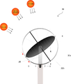
도 1은 본 발명에 따른 태양열과 풍력을 이용한 가로등의 구조를 나타낸 조감이다.
도 2는 태양광 집광판의 수평축 회전을 볼 수 있는 측면도이다.
도 3은 태양광 집광판의 회전을 이해하기 쉽게 배면 45°상부에서 본 배면도이다.1 is a bird's eye view showing the structure of a street lamp using solar and wind power according to the present invention.
2 is a side view of the horizontal axis of the solar light collecting plate can be seen.
FIG. 3 is a rear view of the solar panel of the solar light collecting plate viewed from the upper 45 ° back.
이하, 본 발명에 첨부된 도면을 참조하여 본 발명의 구체적 기술적 특성을 상세히 설명하기로 한다.Hereinafter, specific technical features of the present invention will be described in detail with reference to the accompanying drawings.
본 발명은 태양열과 풍력을 이용한 가로등에 있어서, 상단에 지구본 형태의 회전형 태양광 집광판(5)과, 가로등주의 중앙축(12)을 따라 수직방향으로 설치된 풍력발전기를 포함하여 하단 콘트롤 박스(13) 등을 포함한다.The present invention is a street lamp using solar and wind power, including a rotary solar
이와같은 태양광 집광판(5)은 태양광을 이용하여 전류를 생성시키는 것으로서, 예를 들면 태양광의 에너지에 의해서 내부에서 전자가 이동하여 전류를 생산하는 일반적인 쏠라셀과 같은 재료이다. 이와 같은 태양광 집광판(5)에서 발전된 전원은 가로등주의 중앙축(12)의 하단에 마련된 축전지(14)에 저장되어 각종 용도로 활용된다.Such a solar
도 1은 상단의 수직회전축(4)과 수평회전축(6)을 중심으로 회전하는 태양광 집광판(5)과 그 하단에 led 등기구, 수직 풍력팬(9) 및 발전시스템(10,11),그리고 하부의 콘트롤 박스(13) 등 가로등 전체의 구조를 표현한 조감도이다.1 shows a solar
도 1에 도시된 바와 같이, 가로등주 중앙축(12)의 상단에는 반원호형의 고정 프레임(20)이 고정되어 있고, 그 반원호형의 고정 프레임(20)의 양단에는 수평 회전축(6)이 각각 형성되어 열십자형의 프레임(30)이 상기 반원호형의 고정 프레임(20) 내측에 회전가능하게 장착된다.As shown in FIG. 1, a semicircular arc-shaped
상기 열십자형의 프레임(30)은 각각 원형 고리형의 수평 프레임(32a)과, 상기 수평 프레임(32a)에 수직으로 배치된 원형 고리형의 수직 프레임(32b)을 포함하고 있으며, 상기 수평 프레임(32a)의 양측이 상기 반원호형의 고정 프레임(20)의 양단 수평 회전축(6)에 회전가능하게 장착된 것이다. The
이와 같은 열십자형의 프레임(30)은 각각 원형 고리형의 수평 프레임(32a)과, 원형 고리형의 수직 프레임(32b)이 열십자형으로 일체로 고정된 것으로서, 상기 수평 프레임(32a)이 회전하면, 수직 프레임(32b)도 동시에 수평 프레임(32a)을 따라서 회전한다.Such a
그리고 상기 수직 프레임(32b)의 내측에는 태양광 집광판(5)이 장착되어 있는데, 이와 같은 태양광 집광판(5)은 원판형의 구조이고, 수직 프레임(32b)에 대해서 그 상,하단에 각각 수직 회전축(4)이 장착되어 수직 프레임(32b)의 내측에서 회전가능하다.In addition, the solar
도 2는 상단에 지구본 형태의 회전형 태양광 집광판(5)을 측면에서 표현한 측면도로서, 계절별 태양각도의 변화에 따라 수평 회전축(6)을 중심으로 춘추,하,동절기 별로 구동모터(7)에 의하여 회전하며, 그 회전값은 설치지역에 따라 태양의 절기별 고도를 확인하여 콘트롤 박스(13)에서 입력하여 동작시킨다.FIG. 2 is a side view of a rotatable solar
이와 같은 구동모터(7)는 가로등주 중앙축(12)의 상단에 몸체가 고정되고, 그 회전축에는 피니언 기어가 장착되며, 상기 피니언 기어(미 도시)는 상기 원형 고리형의 수직 프레임(32b) 일측에 마련된 래크기어(미 도시)에 치차 결합하고 있다.The
또한 이와 같은 구동모터(7)는 축전지(14)로부터 공급된 전원을 이용하여 동작되며, 이와 같은 구동모터(7)가 회전하면, 피니언 기어는 수직 프레임(32b)의 래크 기어에 맞물려서 상기 수평 회전축(6)을 중심으로 수직 프레임(32b)을 돌려서, 상기 수직 프레임(32b)의 내부에 위치된 태양광 집광판(5)을 설치지역에 따라 태양의 절기별 고도에 맞춰서 태양에 마주하도록 경사 조절한다.In addition, such a
이와 같은 작동은 콘트롤 박스(13)에 사전에 태양의 절기별 고도에 해당하는 정보를 입력하여 계절별로 동작시킨다.This operation is operated in season by inputting the information corresponding to the season altitude of the sun in advance in the control box (13).
또한 전기절감을 위하여 상기 콘트롤 박스(13)에 입력된 시간에 의하여 연 5회 이내의 횟수로 구동하게 하고, 수직 프레임(32b)에는 일정간격으로 센서(1)를 설치하여 태양의 절기별 고도에 맞춰서 구동모터(7)의 작동을 정지할 수 있게 한다.In addition, by the time input to the
도 3은 상부에 회전형 태양광 집광판(5)을 장착하고, 배면 상부 45°정도에서 본 배면도로서, 시간대별 태양의 이동에 따라 수직 회전축(4)을 중심으로 구동모터(2)에 의하여 회전하며, 전기절감을 위하여 콘트롤 박스(13)에 입력된 시간에 의하여 하루 10회 이의 횟수로 구동하게 하고, 센서(1)를 설치하여 정지할 수 있게 하며, 저녁시간 회전의 끝단부에 도달 시, 자동으로 회전의 시작부로 역회전하는 기능을 가지고 있다. FIG. 3 is a rear view of the
즉, 본 발명은 도 3에 도시된 바와 같이, 태양광 집광판(5)이 수직 회전축(4)을 중심으로 수직 프레임(32b)의 내부에서 회전할 수 있다.That is, in the present invention, as shown in FIG. 3, the solar
이와 같은 구조에서, 상기 구동모터(2)는 태양광 집광판(5)의 배면 일측방에 그 몸체가 고정된 것으로서, 그 회전축에는 피니언 기어(미 도시)가 형성되고, 이와 같은 피니언 기어는 수평 프레임(32a)을 따라서 형성된 래크 기어(미 도시)에 치차결합한다.In such a structure, the
이와 같은 구동모터(2)는 축전지(14)로부터 공급된 전원을 이용하여 동작되며, 이와 같은 구동모터(2)가 동작하면, 상기 태양광 집광판(5)의 배면 일측방으로부터 돌출한 피니언 기어가 수평 프레임(32a)의 원주상에 마련된 래크 기어들을 회전이동하면서, 태양광 집광판(5)은 그 상,하부에 형성된 수직 회전축(4)을 통하여, 도 3과 같이 수평 프레임(32a)과 수직 프레임(32b)의 내부에서 회전한다.The driving
또한 상기 수평 프레임(32a)에는 래크기어가 설치된 원주 부분에 일정간격으로 다수의 센서(1)들이 장착되어 상기 구동모터(2)의 회전을 시간대별로 정지시킴으로써 하루 10회 이하의 횟수로 구동모터(2)가 구동 및 정지할 수 있게 하며, 저녁시간 회전의 끝단부 센서(1)에 도달하게 되면, 자동으로 회전의 시작부측의 센서(1)로 역회전시킨다. 이와 같은 작동도 콘트롤 박스(13)에 사전에 입력된 시간에 의하여 하루 10회 이하의 횟수로 상기 구동모터(2)를 구동하게 한다.In addition, the horizontal frame 32a is equipped with a plurality of
또한 본 발명은 곡선형 구조의 기존 풍력팬과는 다르게, 직선형 풍력팬(9)과 이에 직각이 되게 다수의 원형판(8)을 설치한 구조이다.In addition, the present invention is a structure in which a plurality of
종래의 곡선형 풍력팬은 제작의 난이도가 높아서 원가 상승의 요인이 되고, 내구성이나 유지보수상에 어려움을 겪을 수 있으나, 도 1에서 볼 수 있는 직선형 풍력팬(9)은 제작 및 유지보수 측면에서 경쟁력을 가질 수 있으며, 공기의 상하 흐름을 방지하기 위하여 수직팬과 직각이 되게 다수의 원형판(8)을 설치하여 항상 일정한 풍압을 받도록 되어 있다. Conventional curved wind fan has a high difficulty of manufacturing, causing a cost increase, and may suffer from durability or maintenance, but the straight wind fan (9) can be seen in Figure 1 in terms of production and maintenance To have a competitive advantage, and to prevent the flow of air up and down by installing a plurality of
이러한 풍력팬(9)에 연계되는 내부 발전시스템은 중앙 가로등주에 수직으로 권선코일(10)을 설치하고, 권선코일(10)을 축전지(14)에 전기적으로 연결하며, 풍력팬(9)의 원형구조 내부에 정류자(11)를 수직으로 배치하여 소량의 권선코일을 이용하는 기존의 풍력발전과는 달리 최대의 효율을 높일 수 있다.The internal power generation system connected to the
상기 가로등주 콘트롤 박스(13)는 상단 태양광 집광판(5)의 수평 수직 회전용 구동모터(2,7)를 각각 구동시켜주며 스톱 센서(1)를 감지하여 전원을 차단시켜 주고 수직 회전축의 끝단부 센서(1)에 집광판이 도달시, 역회전하여 회전 시작점으로 돌아올 수 있도록 제어해주는 콘트롤 박스로서, 디지털 타이머과 모터구동 시간을 입력할 수 있는 입력장치로 구성되어 있다.The streetlight
상기와 같이 구성된 본 발명에 따른 태양열과 풍력을 이용한 가로등은 계절별 태양각도의 변화에 따라 태양광 집광판(5)을 수평 회전축(6)을 중심으로 회전시켜서 춘추,하,동절기 별로 태양에 마주하도록 배치한다.The street lamp using the solar and wind power according to the present invention configured as described above is disposed so as to face the sun by spring, summer and winter by rotating the solar
이때에는 구동모터(7)가 동작하며, 구동모터(7)의 피니언 기어(미 도시)가 수직 프레임(32b)의 래크 기어(미 도시)에 맞물려서 상기 수평 회전축(6)을 중심으로 수직 프레임(32b)을 돌려서, 상기 수직 프레임(32b)의 내부에 위치된 태양광 집광판(5)을 태양에 마주하도록 경사 조절한다.At this time, the
이때, 본 발명은 전기절감을 위하여 콘트롤 박스(13)에 입력된 시간에 의하여 연 5회 이내의 횟수로 구동하게 하고, 수직 프레임(32b)에는 일정간격으로 센서(1)를 설치하여 태양의 절기별 고도에 맞춰서 정지할 수 있도록 하는 것이다.At this time, the present invention is driven by the number of times within five times a year by the time input to the
또한 본 발명은 아침부터 저녁까지 시간대별 태양의 이동에 따라 태양광 집광판(5)을 태양에 마주하도록 회전시킨다.In addition, the present invention rotates the solar light collecting plate (5) to face the sun according to the movement of the sun by time from morning to evening.
이때에는 도 3에 도시된 바와 같이, 구동모터(2)를 회전시키며, 구동모터(2)의 피니언 기어(미 도시)가 수평 프레임(32a)의 래크 기어(미 도시) 상에서 회전이동하면서, 태양광 집광판(5)을 그 상,하부에 형성된 수직 회전축(4)을 통하여 회전시키고, 아침부터 저녁까지 시간대별 태양의 이동에 따라 태양광 집광판(5)을 태양에 마주하도록 회전시킨다.In this case, as shown in FIG. 3, the
또한 상기 구동모터(2)가 저녁시간 회전의 끝단부 센서(1)에 도달하게 되면, 자동으로 회전의 시작부 센서(1)로 역회전시키며, 이와 같은 작동도 콘트롤 박스(13)에 사전에 입력된 시간에 의하여 하루 10회 이하의 횟수로 구동되게 한다.In addition, when the driving
또한 본 발명은 직선형 풍력팬(9)과 다수의 원형판(8)을 조합한 구조로 설치하여 항상 일정한 풍압을 받는다. 따라서 작은 바람에 의해서도 원활하게 풍력팬(9)이 회전하여 내부 발전시스템을 통하여 발전할 수 있다.In addition, the present invention is installed in a structure in which the
이와 같이 본 발명품은 태양열과 풍력을 가장 효율적으로 활용하여 별도의 전력공급 없이 반 영구적으로 활용할 수 있는 가로등에 대한 것이며, 이 기술은 도시환경이나 해안도로, 공원 등 어떤 장소에도 적용할 수 있는 장점이 있다.As described above, the present invention relates to a street lamp that can be used semi-permanently without using a separate power supply by utilizing solar and wind most efficiently, and this technology can be applied to any place such as an urban environment, a coastal road or a park. have.
본 발명은 상기에서 도면을 참조하여 특정 실시 예에 관련하여 상세히 설명하였지만 본 발명은 이와 같은 특정 구조에 한정되는 것은 아니다. 당 업계의 통상의 지식을 가진 자라면 이하의 특허청구범위에 기재된 본 발명의 기술 사상 및 권리범위를 벗어나지 않고서도 본 발명을 다양하게 수정 또는 변경시킬 수 있을 것이다. 예를 들면, 구동모터의 회전축에 피니언 기어가 장착되고, 이에 결합하도록 수평 프레임 또는 수직 프레임에 래크기어를 장착한 것으로 설명되었지만, 이와는 다르게 치차 결합이 아닌 마찰결합, 즉 구동모터의 회전축에는 회전 롤러를 구비하고, 수평 프레임 또는 수직 프레임에는 회전 롤러의 슬립을 방지하는 마찰 면을 형성하여 상기 구동모터의 작동으로 수평 프레임과 수직 프레임을 회전시킬 수 있음은 물론이다. 그렇지만 그와 같은 단순한 설계적인 수정 또는 변형 구조들은 모두 명백하게 본 발명의 권리범위 내에 속하게 됨을 미리 밝혀 두고자 한다.Although the present invention has been described in detail with reference to specific embodiments thereof with reference to the accompanying drawings, the present invention is not limited to such specific structures. Those skilled in the art may variously modify or change the present invention without departing from the spirit and scope of the present invention as set forth in the claims below. For example, it has been described that the pinion gear is mounted on the rotational axis of the drive motor, and the rack gear is mounted on the horizontal frame or the vertical frame so as to be coupled thereto. A roller is provided, and the horizontal frame or the vertical frame is provided with a friction surface that prevents slippage of the rotating roller, so that the horizontal frame and the vertical frame can be rotated by the operation of the drive motor. However, it is intended that the present invention cover the modifications and variations of this invention provided they come within the scope of the appended claims and their equivalents.
1: 스톱센서 2: 수직축 구동모터
3: 기어부 4: 수직 회전축
5: 태양광 집광판 6: 수평 회전축
7: 수평축 구동모터 8: 바람차단 원형판
9: 풍력팬 10: 권선코일
11: 정류자 12: 가로등주 중앙축
13: 콘트롤 박스 14: 축전지
20: 반원호형 고정 프레임 30: 열십자형의 프레임
32a: 수평 프레임 32b: 수직 프레임 1: stop sensor 2: vertical drive motor
3: gear portion 4: vertical axis of rotation
5: solar light collector 6: horizontal axis of rotation
7: Horizontal axis drive motor 8: Wind block round plate
9: wind fan 10: winding coil
11: commutator 12: central axis of street lamp
13: control box 14: storage battery
20: semicircular fixed frame 30: crisscross frame
32a:
Claims (5)
가로등주 중앙축의 상단에 설치된 반원호형의 고정 프레임 내측에서 수평 회전축을 통하여 회전가능하게 지구본 형태의 수평 프레임과 수직 프레임이 열십자형으로 장착되고, 상기 수직 프레임의 내측에서 수직 회전축을 중심으로 회전가능하게 설치된 회전형 태양광 집광판;
가로등주의 중앙축을 따라 수직방향으로 설치된 풍력발전기; 및
가로등주의 중앙축의 하단 콘트롤 박스와 축전지;를 포함하고, 상기 태양광 집광판은 계절별 태양각도의 변화에 따라 수평 회전축을 중심으로 구동모터에 의하여 수직 프레임의 회전에 따라서 춘추,하,동절기별로 회전하며, 일일 시간대별 태양의 이동에 따라 수직 회전축을 중심으로 구동모터에 의하여 수평 프레임을 따라서 그 원주방향으로 회전하여 일일 시간대별, 절기별로 태양광의 각도를 태양광 집광판에 직각으로 유지할 수 있도록 구성된 것임을 특징으로 하는 태양열과 풍력을 이용한 가로등.In the street light using solar and wind power,
A horizontal frame and a vertical frame having a globe shape are mounted in a cross shape so as to be rotatable through a horizontal rotating shaft inside a semi-circular fixed frame installed at an upper end of the central axis of the street lamp. Rotatable solar light collecting plate;
A wind turbine installed vertically along the central axis of the street lamp; And
A lower control box and a storage battery of a central axis of a street lamp; and the solar light collecting plate rotates by spring, summer, and winter in accordance with the rotation of a vertical frame by a driving motor about a horizontal rotation axis according to a change in the solar angle of each season. It is configured to maintain the angle of sunlight at right angles to the solar light collecting plate by day and season by rotating in the circumferential direction along the horizontal frame by the drive motor around the vertical rotation axis according to the movement of the sun by daily time zone. Street lights using solar and wind power.
Priority Applications (1)
| Application Number | Priority Date | Filing Date | Title |
|---|---|---|---|
| KR1020110049197A KR101277832B1 (en) | 2011-05-24 | 2011-05-24 | Street lamp using sweeping mould solar and wind power generation |
Applications Claiming Priority (1)
| Application Number | Priority Date | Filing Date | Title |
|---|---|---|---|
| KR1020110049197A KR101277832B1 (en) | 2011-05-24 | 2011-05-24 | Street lamp using sweeping mould solar and wind power generation |
Publications (2)
| Publication Number | Publication Date |
|---|---|
| KR20120131026A true KR20120131026A (en) | 2012-12-04 |
| KR101277832B1 KR101277832B1 (en) | 2013-06-21 |
Family
ID=47514973
Family Applications (1)
| Application Number | Title | Priority Date | Filing Date |
|---|---|---|---|
| KR1020110049197A KR101277832B1 (en) | 2011-05-24 | 2011-05-24 | Street lamp using sweeping mould solar and wind power generation |
Country Status (1)
| Country | Link |
|---|---|
| KR (1) | KR101277832B1 (en) |
Cited By (3)
| Publication number | Priority date | Publication date | Assignee | Title |
|---|---|---|---|---|
| CN104253575A (en) * | 2013-06-26 | 2014-12-31 | 苏州东安新高能源科技有限公司 | Wind-solar complementary power generating system and installing method thereof |
| CN105889859A (en) * | 2015-10-02 | 2016-08-24 | 蒋超 | LED rod type lighting device capable of being charged by solar energy and wind energy day and night |
| US9657345B2 (en) | 2012-11-19 | 2017-05-23 | Samsung Electronics Co., Ltd. | Polynucleotide and use thereof |
Families Citing this family (4)
| Publication number | Priority date | Publication date | Assignee | Title |
|---|---|---|---|---|
| CN106122880B (en) * | 2016-07-06 | 2018-09-21 | 浙江晶通新能源科技有限公司 | A kind of energy-saving LED road lamp |
| CN106195873B (en) * | 2016-07-06 | 2018-11-06 | 江苏科德照明电气有限公司 | A kind of high heat dissipation street lamp |
| CN106195875B (en) * | 2016-07-06 | 2019-01-01 | 中山市威能仕照明电器制造有限公司 | A kind of wind light mutual complementing LED both arms energy-conserving road lamp |
| CN106160643A (en) * | 2016-08-31 | 2016-11-23 | 四川蜀旺新能源股份有限公司 | A kind of device utilizing city illumination lamp stand to carry out parallel network power generation |
Family Cites Families (3)
| Publication number | Priority date | Publication date | Assignee | Title |
|---|---|---|---|---|
| KR200305591Y1 (en) | 2002-11-26 | 2003-02-26 | 김용석 | the street lamp using solar and wind power generation |
| KR100720925B1 (en) | 2005-09-07 | 2007-05-22 | 대한테크렌(주) | Condensing apparatus for solar photovoltaic generator |
| KR101023014B1 (en) | 2009-11-03 | 2011-03-24 | 태창엔이티 주식회사 | Hybrid streetlight |
-
2011
- 2011-05-24 KR KR1020110049197A patent/KR101277832B1/en active IP Right Grant
Cited By (3)
| Publication number | Priority date | Publication date | Assignee | Title |
|---|---|---|---|---|
| US9657345B2 (en) | 2012-11-19 | 2017-05-23 | Samsung Electronics Co., Ltd. | Polynucleotide and use thereof |
| CN104253575A (en) * | 2013-06-26 | 2014-12-31 | 苏州东安新高能源科技有限公司 | Wind-solar complementary power generating system and installing method thereof |
| CN105889859A (en) * | 2015-10-02 | 2016-08-24 | 蒋超 | LED rod type lighting device capable of being charged by solar energy and wind energy day and night |
Also Published As
| Publication number | Publication date |
|---|---|
| KR101277832B1 (en) | 2013-06-21 |
Similar Documents
| Publication | Publication Date | Title |
|---|---|---|
| KR101277832B1 (en) | Street lamp using sweeping mould solar and wind power generation | |
| KR101788672B1 (en) | Street lamp having solar energy tracking system and wind power generation | |
| US8288884B1 (en) | Wind turbine with integrated solar panels | |
| KR101146117B1 (en) | Compound generator using solar and wind | |
| CN104467637B (en) | Self-adapting solar energy electricity generation system | |
| KR101060156B1 (en) | A hybrid generate electricity system for a roof type | |
| CN102255566B (en) | Wind-light complementary generating device | |
| KR20160004245U (en) | Street lamp having solar energy tracking system and wind power generation | |
| KR20120051893A (en) | Power generator of hybrid type | |
| CN202144978U (en) | Solar street lamp | |
| CN110319403A (en) | Energy-saving environment-friendly road lamp | |
| CN203070112U (en) | Solar cell panel tracking system | |
| CN207880695U (en) | A kind of solar wind-energy new energy street lamp | |
| CN202148987U (en) | Solar and wind energy generator | |
| CN203115813U (en) | Solar street lamp automatically tracking solar illumination | |
| CN212029349U (en) | Solar street lamp with traffic light prompt function for intersection | |
| CN205195636U (en) | But automatically regulated's solar cell panel support | |
| CN103673190A (en) | Renewable energy ventilator | |
| CN202157905U (en) | Wind-light complemented generating set | |
| KR20120133932A (en) | Solar powered street lamp and controlling method thereof | |
| KR101362447B1 (en) | Solar powered street lights having a wind power generator | |
| RU2528626C2 (en) | Self-contained power generator for street lamp | |
| KR102366428B1 (en) | Solar rotary module | |
| KR20100013026U (en) | Hybrid street light | |
| KR101628277B1 (en) | Solar tracking device for controlling multi-solar panels simultaneously |
Legal Events
| Date | Code | Title | Description |
|---|---|---|---|
| A201 | Request for examination | ||
| E701 | Decision to grant or registration of patent right | ||
| GRNT | Written decision to grant | ||
| FPAY | Annual fee payment |
Payment date: 20170716 Year of fee payment: 5 |
|
| FPAY | Annual fee payment |
Payment date: 20180618 Year of fee payment: 6 |
|
| R401 | Registration of restoration |