KR20120123335A - Hvac control system and method - Google Patents
Hvac control system and method Download PDFInfo
- Publication number
- KR20120123335A KR20120123335A KR1020127018616A KR20127018616A KR20120123335A KR 20120123335 A KR20120123335 A KR 20120123335A KR 1020127018616 A KR1020127018616 A KR 1020127018616A KR 20127018616 A KR20127018616 A KR 20127018616A KR 20120123335 A KR20120123335 A KR 20120123335A
- Authority
- KR
- South Korea
- Prior art keywords
- building
- hvac
- model
- heating
- thermal
- Prior art date
Links
Images


Classifications
-
- F—MECHANICAL ENGINEERING; LIGHTING; HEATING; WEAPONS; BLASTING
- F24—HEATING; RANGES; VENTILATING
- F24F—AIR-CONDITIONING; AIR-HUMIDIFICATION; VENTILATION; USE OF AIR CURRENTS FOR SCREENING
- F24F11/00—Control or safety arrangements
- F24F11/30—Control or safety arrangements for purposes related to the operation of the system, e.g. for safety or monitoring
- F24F11/46—Improving electric energy efficiency or saving
- F24F11/47—Responding to energy costs
-
- F—MECHANICAL ENGINEERING; LIGHTING; HEATING; WEAPONS; BLASTING
- F24—HEATING; RANGES; VENTILATING
- F24F—AIR-CONDITIONING; AIR-HUMIDIFICATION; VENTILATION; USE OF AIR CURRENTS FOR SCREENING
- F24F11/00—Control or safety arrangements
- F24F11/30—Control or safety arrangements for purposes related to the operation of the system, e.g. for safety or monitoring
-
- F—MECHANICAL ENGINEERING; LIGHTING; HEATING; WEAPONS; BLASTING
- F24—HEATING; RANGES; VENTILATING
- F24F—AIR-CONDITIONING; AIR-HUMIDIFICATION; VENTILATION; USE OF AIR CURRENTS FOR SCREENING
- F24F11/00—Control or safety arrangements
- F24F11/62—Control or safety arrangements characterised by the type of control or by internal processing, e.g. using fuzzy logic, adaptive control or estimation of values
- F24F11/63—Electronic processing
- F24F11/64—Electronic processing using pre-stored data
-
- G—PHYSICS
- G05—CONTROLLING; REGULATING
- G05B—CONTROL OR REGULATING SYSTEMS IN GENERAL; FUNCTIONAL ELEMENTS OF SUCH SYSTEMS; MONITORING OR TESTING ARRANGEMENTS FOR SUCH SYSTEMS OR ELEMENTS
- G05B15/00—Systems controlled by a computer
- G05B15/02—Systems controlled by a computer electric
-
- G—PHYSICS
- G05—CONTROLLING; REGULATING
- G05B—CONTROL OR REGULATING SYSTEMS IN GENERAL; FUNCTIONAL ELEMENTS OF SUCH SYSTEMS; MONITORING OR TESTING ARRANGEMENTS FOR SUCH SYSTEMS OR ELEMENTS
- G05B17/00—Systems involving the use of models or simulators of said systems
- G05B17/02—Systems involving the use of models or simulators of said systems electric
-
- G—PHYSICS
- G05—CONTROLLING; REGULATING
- G05D—SYSTEMS FOR CONTROLLING OR REGULATING NON-ELECTRIC VARIABLES
- G05D23/00—Control of temperature
- G05D23/19—Control of temperature characterised by the use of electric means
- G05D23/1917—Control of temperature characterised by the use of electric means using digital means
-
- F—MECHANICAL ENGINEERING; LIGHTING; HEATING; WEAPONS; BLASTING
- F24—HEATING; RANGES; VENTILATING
- F24F—AIR-CONDITIONING; AIR-HUMIDIFICATION; VENTILATION; USE OF AIR CURRENTS FOR SCREENING
- F24F11/00—Control or safety arrangements
- F24F11/30—Control or safety arrangements for purposes related to the operation of the system, e.g. for safety or monitoring
- F24F11/46—Improving electric energy efficiency or saving
-
- F—MECHANICAL ENGINEERING; LIGHTING; HEATING; WEAPONS; BLASTING
- F24—HEATING; RANGES; VENTILATING
- F24F—AIR-CONDITIONING; AIR-HUMIDIFICATION; VENTILATION; USE OF AIR CURRENTS FOR SCREENING
- F24F11/00—Control or safety arrangements
- F24F11/50—Control or safety arrangements characterised by user interfaces or communication
- F24F11/52—Indication arrangements, e.g. displays
-
- F—MECHANICAL ENGINEERING; LIGHTING; HEATING; WEAPONS; BLASTING
- F24—HEATING; RANGES; VENTILATING
- F24F—AIR-CONDITIONING; AIR-HUMIDIFICATION; VENTILATION; USE OF AIR CURRENTS FOR SCREENING
- F24F2120/00—Control inputs relating to users or occupants
-
- F—MECHANICAL ENGINEERING; LIGHTING; HEATING; WEAPONS; BLASTING
- F24—HEATING; RANGES; VENTILATING
- F24F—AIR-CONDITIONING; AIR-HUMIDIFICATION; VENTILATION; USE OF AIR CURRENTS FOR SCREENING
- F24F2120/00—Control inputs relating to users or occupants
- F24F2120/20—Feedback from users
-
- F—MECHANICAL ENGINEERING; LIGHTING; HEATING; WEAPONS; BLASTING
- F24—HEATING; RANGES; VENTILATING
- F24F—AIR-CONDITIONING; AIR-HUMIDIFICATION; VENTILATION; USE OF AIR CURRENTS FOR SCREENING
- F24F2140/00—Control inputs relating to system states
- F24F2140/60—Energy consumption
-
- G—PHYSICS
- G05—CONTROLLING; REGULATING
- G05B—CONTROL OR REGULATING SYSTEMS IN GENERAL; FUNCTIONAL ELEMENTS OF SUCH SYSTEMS; MONITORING OR TESTING ARRANGEMENTS FOR SUCH SYSTEMS OR ELEMENTS
- G05B2219/00—Program-control systems
- G05B2219/20—Pc systems
- G05B2219/26—Pc applications
- G05B2219/2614—HVAC, heating, ventillation, climate control
-
- G—PHYSICS
- G05—CONTROLLING; REGULATING
- G05B—CONTROL OR REGULATING SYSTEMS IN GENERAL; FUNCTIONAL ELEMENTS OF SUCH SYSTEMS; MONITORING OR TESTING ARRANGEMENTS FOR SUCH SYSTEMS OR ELEMENTS
- G05B2219/00—Program-control systems
- G05B2219/20—Pc systems
- G05B2219/26—Pc applications
- G05B2219/2642—Domotique, domestic, home control, automation, smart house
Landscapes
- Engineering & Computer Science (AREA)
- General Engineering & Computer Science (AREA)
- Physics & Mathematics (AREA)
- Chemical & Material Sciences (AREA)
- Combustion & Propulsion (AREA)
- Mechanical Engineering (AREA)
- Signal Processing (AREA)
- General Physics & Mathematics (AREA)
- Automation & Control Theory (AREA)
- Fuzzy Systems (AREA)
- Mathematical Physics (AREA)
- Air Conditioning Control Device (AREA)
Abstract
건물의 난방(Heating), 환기(Ventilation) 및 공기조화(Air Conditioning)(HVAC) 시스템을 제어하는 방법이 제공된다. 상기 방법은 (a) 건물의 초기 열적 모델(initial thermal model)을 개발하고, 이 열적 모델을 시간이 경과함에 따라 지속적으로 업데이트하는 단계, (b) 건물을 위한 일일(daily) HVAC 작동 계획을 지속적으로 개발하기 위해 상기 열적 모델을 이용하는 단계 및 (c) 현재(current) HVAC 작동 계획을 지속적으로 점검(examining)하고 현재 HVAC 작동의 얼라인먼트(alignment)를 상기 현재 HVAC 작동 계획으로 최적화하는 단계를 포함한다.Methods are provided for controlling the heating, ventilation and air conditioning (HVAC) systems of a building. The method comprises the steps of (a) developing an initial thermal model of the building, continuously updating the thermal model over time, and (b) maintaining a daily HVAC operation plan for the building. Using the thermal model to develop a system and (c) continuously examining a current HVAC operation plan and optimizing an alignment of current HVAC operation to the current HVAC operation plan. .
Description
본 발명은 건물의 난방(Heating), 환기(Ventilation) 및 공기조화(Air Conditioning)(HVAC)를 위한 효율적인 시스템 및 방법에 관한 것이다. 특히, 본 발명은 건물에서 사용되는 더욱 효율적인 기후 제어 시스템(climate control system)을 제공한다.The present invention relates to efficient systems and methods for heating, ventilation and air conditioning (HVAC) of buildings. In particular, the present invention provides a more efficient climate control system for use in buildings.
난방(Heating), 환기(Ventilation) 및 공기조화(Air Conditioning)(HVAC) 시스템의 광범위한 보급은 건물의 디자인과 형태에 큰 유연성을 가져다 주었다. 극심한 기후 조건에서도 실내 쾌적성을 제공하였고, 열악한 열적 성능 하에서도 거주하기 적합한 건물들을 만드는데 일조하였다. 그러나, 이러한 유연성이 아무런 대가 없이 얻어진 것은 아니다. 예를 들어, 호주에서는, 대체적으로 HVAC가 상업 건물 에너지 사용량의 60% 이상을 차지[Australian Greenhouse Office, 1999]하고, 온실가스 배출의 주요 원인이 되고 있으며, 전력망(electricity network)에서 수요가 증가하고 있다.The widespread deployment of Heating, Ventilation and Air Conditioning (HVAC) systems has given great flexibility to the design and shape of buildings. It provided indoor comfort even in extreme weather conditions and helped to make buildings suitable for living under poor thermal performance. However, this flexibility was not obtained without any cost. For example, in Australia, HVAC accounts for more than 60% of commercial building energy use [Australian Greenhouse Office, 1999], is a major source of greenhouse gas emissions, and demand is growing in the electricity network. have.
최적의 HVAC 제어 전략들을 위하여 수행되는 주목할 만한 연구가 있다. 이들 전략들은 보통 각각 별개로 고려하는 것이기는 하나, 쾌적성, 전력망 상호작용 및 온실가스 배출 측면을 고려한다. 예를 들어, Braun et al. (1990, 2001)은 에너지 로드 형성(energy load shaping)을 위해 건물 열식 질량(building thermal mass)을 사용하는 것을 연구하였고, Eto (2007)는 전력망에 운전예비(spinning reserve)를 제공하는 것에 공기조화(air-conditioning)가 유용함을 밝혀내었다. Fanger (19617)는 열적 쾌적성(thermal comfort)에 대한 연구를 개척하였고, 열적 쾌적성이 생산성에 미치는 영향은 최근에 Seppanen et al. (2006)에 의하여 더 연구되었다. 온실가스 배출 문제는, 열병합발전 시스템(예를 들어, White and Ward(2006))이 배출을 줄이기 위해 폐열(waste heat)과 대체연료를 직접적으로 이용하기는 하였으나, 전체 에너지 절약 전략의 일부로서 달성되었다.There is noteworthy research carried out for optimal HVAC control strategies. Although these strategies are usually considered separately, they also consider aspects of comfort, grid interactions, and greenhouse gas emissions. For example, Braun et al . (1990, 2001) studied the use of building thermal mass for energy load shaping, and Eto (2007) investigated air conditioning in providing spinning reserves to the grid. (air-conditioning) has proved useful. Fanger (19617) pioneered the study of thermal comfort, and the impact of thermal comfort on productivity has recently been described in Seppanen et al . (2006). The greenhouse gas emissions problem was achieved as part of the overall energy saving strategy, although cogeneration systems (eg White and Ward (2006)) used waste heat and alternative fuels directly to reduce emissions. It became.
HVAC 시스템은 상업 건물의 제어 설정점(control set point)으로 보통 온도를 사용한다. 밸브와 댐퍼(damper)의 위치, 팬(fan)의 속도 등을 포함한 HVAC 플랜트는 주어진 온도 설정점을 달성하도록 제어된다. 최신식의 HVAC 시스템은 로드 차단 요구(load shedding request)에 근거하여 온도를 변화시킬 수는 있으나, 일반적으로 이 온도 설정점은 고정된다.HVAC systems usually use temperature as a control set point in a commercial building. The HVAC plant, including valve and damper positions, fan speed, etc., is controlled to achieve a given temperature set point. State-of-the-art HVAC systems can change temperature based on load shedding requests, but typically this temperature set point is fixed.
본 발명의 목적은 몇몇의 바람직한 특징들을 가지는 개선된 형태의 HVAC 제어 시스템을 제공하는 것에 있다.It is an object of the present invention to provide an improved type of HVAC control system having some desirable features.
본 발명의 일측에 따르면, 건물의 난방(Heating), 환기(Ventilation) 및 공기조화(Air Conditioning)(HVAC) 시스템을 제어하는 방법이 제공된다. 상기 방법은 (a) 건물의 초기 열적 모델(initial thermal model)을 개발(develop)하고, 이 열적 모델을 시간이 경과함에 따라 지속적으로 업데이트하는 단계, (b) 건물을 위한 일일(daily) HVAC 작동 계획을 지속적으로 개발하기 위해 상기 열적 모델을 이용하는 단계 및 (c) 현재(current) HVAC 작동 계획을 지속적으로 점검(examining)하고 현재 HVAC 작동의 얼라인먼트(alignment)를 이 계획으로 최적화하는 단계를 포함한다.According to one aspect of the invention, there is provided a method of controlling a heating, ventilation and air conditioning (HVAC) system of a building. The method comprises the steps of (a) developing an initial thermal model of the building and continuously updating the thermal model over time, (b) operating a daily HVAC for the building. Using the thermal model to continuously develop a plan, and (c) continuously reviewing the current HVAC operation plan and optimizing the alignment of current HVAC operation with the plan. .
열적 모델은 건물의 이력 열적 데이터(historical thermal data)에 피팅된(fit) 일련의 파라미터를 사용한다. 열적 모델은 구간적 다항식(piecewise polynomial) 모델일 수 있다. 초기 열적 모델은 실질적으로 매일 반복적으로 업데이트된다. 일일 작동 계획은 사용자의 쾌적성(comfort), 소비전력 및 전력비용(power cost)을 포함하는 작동자 선호사항의 조합을 최적화한 것이다. 작동자 선호사항 외에, 외부 입력(external input)은 작동 계획이 전기 비용 데이터(electricity pricing data), 일기예보(weather forecast) 및 사용자 쾌적성 만족 데이터(occupant comfort satisfaction data)를 포함하도록 한다. 일일 HVAC 작동 계획은 실질적으로 매 5분 마다 다시 계산된다. 현재 HVAC 작동의 얼라인먼트(alignment)를 현재 HVAC 작동 계획으로 최적화시키는 것은 실질적으로 매 10초 마다 시도될 수 있다.The thermal model uses a set of parameters that fit into the historical thermal data of the building. The thermal model may be a piecewise polynomial model. The initial thermal model is updated substantially every day. The daily operation plan optimizes the combination of operator preferences, including user comfort, power consumption, and power cost. In addition to operator preferences, external input allows the operation plan to include electrical pricing data, weather forecasts, and user comfort satisfaction data. The daily HVAC operation plan is substantially recalculated every 5 minutes. Optimizing the alignment of current HVAC operation to the current HVAC operation plan can be attempted substantially every 10 seconds.
본 발명의 다른 일측에 따르면, 건물의 난방(Heating), 환기(Ventilation) 및 공기조화(Air Conditioning)(HVAC) 시스템을 제어하는 방법이 제공된다. 상기 방법은 (a) 건물의 열적 모델을 결정하는 단계, (b) 건물 사용자를 위한 예상 인체 쾌적성 모델(expected human comfort model)을 결정하는 단계, (c) 건물의 HVAC 작동 계획을 계산하는데 상기 예상 인체 쾌적성 모델을 주요 인자(prime factor)로 사용하는 단계를 포함한다.According to another aspect of the present invention, there is provided a method for controlling a heating, ventilation and air conditioning (HVAC) system of a building. The method includes (a) determining a thermal model of the building, (b) determining an expected human comfort model for the building user, and (c) calculating a HVAC operation plan for the building. Using the predicted human comfort model as a prime factor.
인체 쾌적성 모델은 상업 건물의 사용자들로부터의 피드백 데이터에 의한 개인 쾌적성 데이터(personal comfort data)로 증강(augment)될 수 있다. 인체 쾌적성 모델은 ASHRAE(미국공조냉동공학회) 표준 쾌적성 모델로부터 유도될 수 있다. The human comfort model may be augmented with personal comfort data by feedback data from users of a commercial building. The human comfort model can be derived from the ASHRAE standard comfort model.
일실시예에 따른 열적 모델은 다음의 형태를 가진다.The thermal model according to one embodiment has the following form.
![]()
![]()
여기서, ![]()
![]()
![]()
![]()
![]()
![]()
![]()
![]()
![]()
![]()
![]()
![]()
![]()
![]()
![]()
![]()
![]()
![]()
![]()
![]()
![]()
![]()
![]()
![]()
![]()
![]()
![]()
![]()
10은 다른 파라미터들과 동일한 범위의 파라미터 ![]()
![]()
다른 실시예에서, 열적 모델은 실질적으로 다음과 같은 형태를 가질 수 있다.In another embodiment, the thermal model may have a form substantially as follows.
![]()
![]()
여기서, ![]()
![]()
![]()
![]()
![]()
![]()
![]()
![]()
![]()
![]()
![]()
![]()
이상적으로, ![]()
![]()
![]()
![]()
상기 수학식의 첫 번째 부분은 유효냉방온도(effective cooling temperature,![]()
![]()
![]()
![]()
![]()
![]()
![]()
![]()
![]()
![]()
![]()
![]()
![]()
![]()
![]()
![]()
![]()
![]()
![]()
![]()
상술한 바람직한 형태에서, 상기 베이스라인 함수(baseline function)는 그 주(week)의 현재 일(current day)에 따라 변화하는 것이 바람직하다. 더욱 바람직하게는, 베이스라인 함수는 하루 중 고정된 특정 시점에 추정되는 삼각형 기저 함수(triangular basis function)의 조합이다.In the preferred form described above, the baseline function preferably changes according to the current day of the week. More preferably, the baseline function is a combination of triangular basis functions that are estimated at a specific point in time of the day.
대표적인 실시예들에 관한 다음의 설명과 첨부된 도면 및 특허청구범위로부터, 본 발명의 이점 및 장점은 본 발명과 관련된 분야의 통상의 기술자에게 명확하게 될 것이다.
도 1은 HVAC 시스템의 작동 환경을 나타내는 개략도이다.
도 2는 바람직한 실시예의 옵티쿨(Opticool) 시스템의 개략적 블록도이다.
도 3은 상업 건물 모델 개발의 기능성(functionality)을 개략적으로 나타낸 것이다.
도 4는 쾌적성 존 제어(comfort based zone control)를 개략적으로 나타낸 것이다.
도 5는 존의 열적 쾌적성 모델링을 위한 인터페이스의 일 예를 나타낸 것이다.
도 6은 상업 건물의 열적 거동을 모델링하기 위한 열적 모델링 루프를 도시한 것이다.
도 7은 상업 건물 전력 계획 루프를 도시한 것이다.
도 8은 온도 제어 루프를 도시한 것이다.
도 9는 상업 건물 존 온도를 모델링한 결과를 나타낸 것이다.
도 10은 본 발명의 일실시예의 건물 모델을 위한 베이스라인 함수를 생성하는데 사용되는 한 세트의 삼각형 기저 함수를 나타낸 것이다.
도 11은 건물 모델의 종일(full day)을 위한 베이스라인 함수를 생성하는데 사용되는 12개의 완전한 세트의 삼각형 기저 함수를 나타낸 것이다.
도 12는 난방 및 냉방 전력 파라미터 간의 관계의 일 예를 도시한 것이다.
도 13은 실제 측정된 온도와 예보된 주위 온도를 머징(merging)하는 프로세스를 도시한 것이다.
도 14는 호주의 상업 건물에서 사용되는 각기 다른 연료의 종류를 도시한 것이다.
도 15는 연료 가격표에 관한 그래픽 사용자 인터페이스의 일 예를 나타낸 것이다. From the following description of the exemplary embodiments, the accompanying drawings and the claims, the advantages and advantages of the present invention will become apparent to those skilled in the art related to the present invention.
1 is a schematic diagram illustrating an operating environment of an HVAC system.
2 is a schematic block diagram of an Opticool system of the preferred embodiment.
3 schematically illustrates the functionality of commercial building model development.
4 schematically illustrates comfort based zone control.
5 illustrates an example of an interface for thermal comfort modeling of a zone.
6 illustrates a thermal modeling loop for modeling the thermal behavior of a commercial building.
7 illustrates a commercial building power plan loop.
8 shows a temperature control loop.
9 shows the results of modeling a commercial building zone temperature.
10 illustrates a set of triangular basis functions used to generate baseline functions for building models of one embodiment of the present invention.
FIG. 11 illustrates twelve complete sets of triangular basis functions used to generate baseline functions for the full day of a building model.
12 shows an example of the relationship between heating and cooling power parameters.
FIG. 13 shows a process of merging the actual measured temperature and the predicted ambient temperature.
Figure 14 illustrates the different fuel types used in commercial buildings in Australia.
15 shows an example of a graphical user interface relating to a fuel price list.
본 발명의 바람직한 실시예들이 첨부된 도면을 참조하여 설명될 것이나, 이는 단지 예를 들어 설명하는 것이다.Preferred embodiments of the present invention will be described with reference to the accompanying drawings, which are merely described by way of example.
바람직한 실시예에서, 시스템의 기본 설정점(fundamental setpoint)이 온도가 아니라 인체 쾌적성(predicted mean vote(PMV, 예상평균온열감) 측정치)인 제어 시스템이 제공된다. 바람직한 실시예들에서, 우선 인체 쾌적성 목표가 정해지고, 이 목표 존 온도로부터, 밸브와 댐퍼의 위치, 팬 속도 등과 같은 플랜트 파라미터가 이 쾌적성 설정점을 달성하도록 제어된다. 이는 보통 온도 설정점 방식에 의존하던 종래기술과 대조를 이룬다. 예를 들어, 동일한 쾌적성 설정점을 달성하는 일정 범위의 서로 다른 온도가 있을 수 있다. 성능적으로(performance wise), 인체 쾌적성을 기본 제어 파라미터로 사용함으로써, 일정 수준의 인체 쾌적성을 유지하면서도 많은 에너지 및 비용 절약을 실현할 수 있다.In a preferred embodiment, a control system is provided wherein the fundamental setpoint of the system is not a temperature but a predicted mean vote (PMV) measurement. In preferred embodiments, a human comfort target is first established and from this target zone temperature, plant parameters such as valve and damper positions, fan speed, etc., are controlled to achieve this comfort set point. This is in contrast to the prior art, which usually relies on the temperature set point method. For example, there may be a range of different temperatures that achieve the same comfort set point. Performance wise, by using human comfort as a basic control parameter, a lot of energy and cost savings can be realized while maintaining a certain level of human comfort.
바람직한 실시예의 시스템은 상업 건물의 열적 모델을 지속적으로 업데이트하는 시스템 및 방법 또한 제공한다. 바람직한 실시예는 지속적으로 조절 가능한 상업 건물의 열적 모델에 의존한다. 바람직한 실시예에서, 제어 시스템은 지속적으로 열적 및 쾌적성 모델을 재학습(re-learn)하고, 이어서 매우 규칙적인 간격(very regular interval)으로 상업 건물의 거동을 재계획(re-plan)한다. 일실시예에서, 다음의 계획된 단계들이 실시된다.The system of the preferred embodiment also provides a system and method for continuously updating the thermal model of a commercial building. The preferred embodiment relies on a thermal model of a continuously adjustable commercial building. In a preferred embodiment, the control system continuously re-learns the thermal and comfort models, and then re-plans the behavior of the commercial building at very regular intervals. In one embodiment, the following planned steps are performed.
하루에 한 번, 시스템은 상업 건물의 열적 모델을 학습하기 위해 이력 성능 데이터(historical performance data)를 사용한다. 이 모델은 하루 중의 특정 시간(time), 주(week) 중의 특정 일(day)에 대한 고찰(consideration)을 포함하고 있어, 생성된 열적 모델은 하루 중의 시간 및 주 중의 일을 인식한다.Once a day, the system uses historical performance data to train the thermal model of a commercial building. The model includes a consideration of a particular time of day, a specific day of the week, and the resulting thermal model recognizes the time of day and the day of the week.
시스템은 매 5분 마다 HVAC 상시(day ahead) 작동을 위한 새로운 계획을 생성한다. 규칙적으로 상시 작동 계획을 업데이트함으로써 시스템은 상업 건물의 사용 패턴 및 날씨 변화에 적응할 수 있다.The system generates a new plan for HVAC day ahead operation every five minutes. By regularly updating the always-on operation plan, the system can adapt to changing usage patterns and weather changes in commercial buildings.
시스템은 상시 작동 계획을 매 10초 마다 점검하고, 현재 상태를 계획 상태와 비교하며, 상시 작동 계획에 따르기 위해 HVAC 플랜트를 제어한다.The system checks the always-on plan every 10 seconds, compares the current state with the planned state, and controls the HVAC plant to comply with the always-on plan.
지속적인 학습과 거동의 재계획은 시스템으로 하여금 상업 건물의 동역학적 변화에 대처할 수 있도록 하는 성능상의 이점을 제공한다. 여기서의 변화는 빠른 변화(예를 들어, 상업 건물의 구역의 열적 응답을 변화시키는 인구의 갑작스런 유입)와 느린 변화(예를 들어, 건물의 서쪽 벽을 따라 나무가 자라 늦은 오후에 열적 응답에 변화가 생기는 경우) 모두를 포함한다. 또한, 실제로, 상업 건물과 HVAC 시스템은 종종 초기 커미셔닝(commissioning) 상태를 벗어나고, 지속적인 학습과 적응이 없이는 HVAC 시스템의 성능이 저하되어 열악한 인체 쾌적성과 낮은 에너지 효율을 야기할 수 있다.Ongoing learning and replanning of behavior offer performance benefits that allow the system to cope with dynamic changes in commercial buildings. Changes here include rapid changes (e.g. sudden influx of populations that change the thermal response of a commercial building's area) and slow changes (e.g. trees grow along the western wall of a building and change in thermal response late in the afternoon). Occurs) In addition, in practice, commercial buildings and HVAC systems often leave the initial commissioning state, and without constant learning and adaptation, the performance of the HVAC system can degrade, resulting in poor human comfort and low energy efficiency.
전형적인 상업 건물의 HVAC 제어는 건물 관리 시스템(상업 건물의 인구를 위하여 온도를 조절하기 위해 냉장장치, 난방장치, 공기조화기의 작동을 측정하고 조절하는 컴퓨터 프로그램 및 관련 하드웨어, 액츄에이터, 센서, 제어기)에 의하여 수행된다.HVAC control in a typical commercial building is a building management system (computer program and associated hardware, actuators, sensors, controllers that measure and regulate the operation of refrigeration units, heating units, and air conditioning units to regulate temperature for the population of commercial buildings). Is performed by.
상업 건물의 에너지 성능을 향상시키기 위해서는 적당한 환경 조건을 제공하면서도 에너지 소비 및 재정 지출과 같은 리소스(resource)를 관리하는 더욱 진보된 접근 방법이 필요하다. 다양한 종류의 리소스와 환경 조건들을 고려하였을 때, 상업 건물의 진보된 제어 시스템의 역할은 불가피하게 경합하는 목표들 간의 균형을 잡아주는 것이다. 적합한 균형을 찾아내는 것은 바람직한 실시예의 주요 기능 중 하나이다.Improving the energy performance of commercial buildings requires a more advanced approach to managing resources such as energy consumption and financial expenditures while providing adequate environmental conditions. Given the various types of resources and environmental conditions, the role of an advanced control system in a commercial building is inevitably a balance between competing goals. Finding a suitable balance is one of the main functions of the preferred embodiment.
통상의 HVAC 제어기에는 포함되지 않는 바람직한 실시예에 따른 HVAC 제어 시스템의 특징은 다음의 사항을 포함한다.Features of the HVAC control system according to a preferred embodiment not included in a conventional HVAC controller include the following.
-서로 다른 에너지 소스 및 이들의 사용 결과의 인지(awareness). 예를 들어, 상업 건물은 난방을 위해 천연가스를, 냉방을 위해 전기를 사용할 수 있다. 서로 다른 종류의 연료는 가격과 온실가스 발생이 다르고, 서로 다른 로드 수준(load level)에서 사용되는 특정 플랜트 아이템(item)들은 서로 다른 효율로 작동한다. Awareness of different energy sources and the results of their use. For example, a commercial building may use natural gas for heating and electricity for cooling. Different types of fuels have different prices and greenhouse gas emissions, and certain plant items used at different load levels operate at different efficiencies.
-반응 제어 원리(reactionary control philosophy)로부터 벗어나기 위한 예보(forecasting)의 사용. 예를 들어, 온화 기후의 많은 상업 건물은 오전에는 난방 모드로 작동하고, 오후에는 냉방 모드로 작동한다. 예측된 날씨와 오후의 열적 로드를 고려함으로써 난방은 적당하게 제한될 수 있고, 따라서 난방 로드 및 냉방 로드 모두를 감소시킬 수 있다.Use of forecasting to deviate from the reactionary control philosophy. For example, many commercial buildings in temperate climates operate in heating mode in the morning and in cooling mode in the afternoon. By considering the predicted weather and afternoon thermal loads, the heating can be appropriately limited, thus reducing both the heating and cooling loads.
-열적 쾌적성 모델 및 온도, 습도, 다른 인자(공기속도, 의류, 활동 수준)의 공칭값(nominal value)을 이용한 인체 쾌적성에 대한 명백한 고찰.Obvious considerations of human comfort using thermal comfort models and nominal values of temperature, humidity and other factors (air speed, clothing, activity level).
-개별 건물 및 인구에 대한 추가적인 고찰. 열적 쾌적성에 대한 연구의 이점에도 불구하고, 쾌적성 및 만족도의 가장 좋은 측정방법은 언제나 건물 인구(occupant) 스스로부터의 피드백이다. 바람직한 실시예는 인구로부터 열적 쾌적성 및 만족도에 관한 피드백을 취득하는 메커니즘을 포함한다. 이러한 사용자 피드백은 국부적인(local) 사용자 선호사항을 반영하기 위한 컴퓨터 열적 모델에 더해져 각 HVAC 존을 위한 쾌적성 오프셋 맵(offset map)을 계산하는데 사용된다. 존 수준(zone level)에서의 실제 사용자 쾌적성 정보를 반영하는 것은 건물 내의 불만족하는 사람들의 비율을 이론적 5% 하계(theoretical 5% lower bound) 아래로 낮출 수 있는 기회를 제공한다. Additional considerations on individual buildings and populations. Despite the benefits of research on thermal comfort, the best measure of comfort and satisfaction is always feedback from the building occupant itself. Preferred embodiments include a mechanism for obtaining feedback about thermal comfort and satisfaction from the population. This user feedback is used to calculate a comfort offset map for each HVAC zone in addition to a computer thermal model to reflect local user preferences. Reflecting real user comfort information at the zone level offers the opportunity to lower the percentage of dissatisfied people in the building below the theoretical 5% lower bound.
-HVAC 시스템을 제어할 때 (i) 유지비, (ii) 온실가스 배출 및 (iii) 인구 열적 쾌적성의 균형을 맞추기 위한 메커니즘.
-Mechanisms for balancing (i) maintenance costs, (ii) greenhouse gas emissions and (iii) population thermal comfort when controlling HVAC systems.
상세 Detail 실시예Example (Implementation details)(Implementation details)
우선, 도 1을 참조하면, 바람직한 실시예의 작동 환경(1)이 개략적으로 도시되어 있다. 이제부터 옵티쿨(OptiCOOL) 제어 시스템(2)으로 명명될 바람직한 실시예는 관리(supervisory) 제어 시스템이다. 즉, 옵티쿨은 기존의 건물 관리 시스템(building management system, BMS)(3)에 접속되거나, BMS의 일부 구성요소이고, 고수준(high-level)의 명령을 BMS에 제공한다. 옵티쿨 제어 시스템은 개별 밸브, 팬 속도, 센싱 인터페이스 또는 제어 장비(4)에 대한 제어는 고려하지 않는다(이러한 저수준 기능은 BMS 시스템(3)의 몫으로 남겨진다.). 옵티쿨은 HVAC 산업 표준 커뮤니케이션 인터페이스를 통해 BMS에 접속(5)하고, 존 온도, 냉방기 및 팬의 설정점과 같은 기초 데이터를 BMS로부터 취득한다. 옵티쿨(3)은 이러한 HVAC 플랜트 데이터를 전기가격, 일기예보, 사용자 쾌적성 데이터 및 건물의 열적 모델을 포함하는 외부 데이터(6)와 결합시켜 BMS(3)에 기본 존 온도 설정점을 제공하는 제어 결정(dicision)을 만든다. 그런 다음, BMS는 이러한 온도 설정점을 달성하기 위해 HVAC 플랜트를 관리한다.First, referring to FIG. 1, the operating
상술하였듯이, 옵티쿨 제어 시스템(3)은 건물 전체 HVAC 플랜트를 위한 상시 또는 유사 시간 주기(similar time period) 작동 계획을 수립하는 것을 기본으로 한다. 옵티쿨 제어 시스템은 도 2에서 더 자세하게 도시되었다. 이러한 계획(10)을 달성하기 위해서는 건물이 날씨와 HVAC 플랜트의 동작에 대해 어떻게 응답하는 가에 대한 열적 모델이 필요하다. 상기 모델(11)은 건물 이력 데이터(historical building data)로부터 “학습(learnt)”된 것이다.As mentioned above, the optical
HVAC 시스템의 지능성 스케쥴링(intelligent scheduling)을 가능케 하려면, 모델은 가능한 제어 동작의 범위에 대한 시스템의 응답을 평가할 수 있어야 한다. 모델이 제어되어 시스템에 일단 맞추어지면, 적절한 제어 전략을 규명하기 위해 가능한 제어 동작의 범위를 평가하는 최적화 루프의 일부로서 사용된다. 도 3은 건물의 열적 성능, HVAC 시스템의 거동, 건물의 열적 로드(load)를 함축적으로 요약한 기본적인 HVAC 모델을 나타낸다. 외부 열적 조건(external thermal condition)과 존 소비전력을 입력으로 사용하면, 모델은 존 조건(zone condition)과의 관계를 학습할 수 있다.To enable intelligent scheduling of the HVAC system, the model must be able to evaluate the system's response to the range of possible control actions. Once the model is controlled and fitted to the system, it is used as part of an optimization loop that evaluates the range of possible control actions to identify the appropriate control strategy. 3 shows a basic HVAC model that implicitly summarizes the thermal performance of a building, the behavior of the HVAC system, and the thermal load of the building. Using external thermal conditions and zone power consumption as inputs, the model can learn the relationship to zone conditions.
설정점 변화 및 외부 조건에 대한 존의 응답을 규명하기 위해서, 몇 가지 모델링 접근 방법이 사용될 수 있다. 몇 가지 실시예에서는 복잡한 학습 기술이 적용된다. 다른 실시예에서, 간단한 “블랙 박스(black box)” 모델은 모델링되는 기초를 이루는 물리적인 프로세스에 관한 명백한 지식 없이, 오로지 입력/출력을 관측함으로써 유도된다. 이러한 후자의 모델은 복잡한 시스템 및 비선형 다변수(multi-variable) 시스템에 특히 유용하고, 상기 접근법은 시스템 파라미터의 수동 설정(manual configuration)을 필요로 하지 않는다. 간단한 다항식 접근법(polynomial approach)이 적합하였다. 이 모델의 장점은 피팅된(fitted) 파라미터 내에서 선형이기 때문에 모델 피팅(fitting) 프로세스를 매우 간략화 시킨다는 것이다. Several modeling approaches can be used to elucidate zone response to set point changes and external conditions. In some embodiments complex learning techniques are applied. In another embodiment, a simple “black box” model is derived by observing input / output only, without explicit knowledge of the underlying physical process being modeled. This latter model is particularly useful for complex systems and non-linear multivariable systems, and this approach does not require manual configuration of system parameters. A simple polynomial approach was suitable. The advantage of this model is that it simplifies the model fitting process very much because it is linear within the fitted parameters.
일실시예에서, 복잡한 학습 프로세스가 HVAC 모델에 구현되었다. 이 프로세스는 건물이 HVAC 냉방 및 난방 전력뿐만 아니라 주위 온도에 대하여도 어떻게 응답하는지를 획득(capture)하는 모델 파라미터의 추정(estimation)를 포함한다. 이러한 모델의 일 예는 아래의 “건물 모델의 예”에서 설명된다.In one embodiment, a complex learning process has been implemented in the HVAC model. This process includes an estimation of model parameters that capture how the building responds to ambient temperature as well as HVAC cooling and heating power. An example of such a model is described in “Example of a Building Model” below.
입력 데이터는 수동으로 입력되거나 각 정보 소스에 알맞은 인터페이스를 이용하게 된다. 예를 들어, 일실시예에서는, 호주 기상청으로부터 일기 예측 데이터를, 호주 전력 시장 운영자로부터 전기 가격 정보를, 그리고 건물 인구 쾌적성 설문 결과를 얻기 위해 자바(Java) 인터페이스가 개발된다.Input data can be entered manually or using the appropriate interface for each information source. For example, in one embodiment, a Java interface is developed to obtain weather forecast data from the Australian Meteorological Administration, electricity price information from Australian power market operators, and building population comfort survey results.
다항식 모델(polynomial model)은 건물의 평균 존 온도를 추정하기 위해 HVAC 전력, 주위 온도 및 규명된 건물의 열적 베이스로드 프로파일(baseload profile)을 이용한다. 이 모델은 다음의 형태를 기본으로 한다.The polynomial model uses the HVAC power, the ambient temperature and the thermal baseload profile of the identified building to estimate the average zone temperature of the building. This model is based on the following form:
![]()
![]()
여기서, ![]()
![]()
![]()
![]()
![]()
![]()
![]()
![]()
![]()
![]()
![]()
![]()
![]()
![]()
종래의 VAV 시스템을 구비하는 시험 건물(trial building)로부터의 데이터를 사용하여, 5분 간격의 16일치의 데이터가 다양한 파라미터를 결정하기 위해 회귀분석(regression analysis)을 이용하여 다항식 모델에 피팅(fit)되었다. 이 데이터 세트에 대한 피팅의 결정계수(coefficient of determination)는 ![]()
![]()
건물 열적 모델(11)이 수립되면, 이 모델은 일기예보 및 전기가격(electricity tariff) 정보(6)와 함께 사용되어, HVAC 플랜트를 위한 소비계획 출력(12)을 만든다. 이 계획은 건물을 위한 시계열적인 전력 프로파일로서, 건물 전체의 예상평균온열감(predicted mean vote, PMV) 쾌적성 설정점을 달성하기 위해 필요한 개별 HVAC 플랜트의 소비전력을 축적(accumulating)하는 것을 기반으로 한다. 이 계획(12)을 찾고 출력하기 위해 최적화 루틴(optimization routine)은 넓은 범위의 가능한(possible) 건물 전력 프로파일을 고려하고, 인구의 쾌적성, 운영 지출, CO2 배출을 우선순위로 고려하는 비용함수(cost function)에 근거하여 어떤 프로파일을 사용할 지 결정한다. 최적(비용함수의 측면에서 최소 비용) 전력 프로파일(12)이 결정되면, 이 프로파일은 건물 전체 쾌적성 프로파일로 변환된다(여기서, 건물 전체 쾌적성 설정점은 하루에 걸친 규칙적인 시간 간격에 대하여 결정된다).Once the building
건물 전체 쾌적성 설정점(15)이 결정되면, 실제 HVAC 제어는 존 제어 결정(16)을 통해 건물의 개별 존들을 분리하여 제어하는 것을 근간으로 한다.Once the overall
도 4(제어 시스템의 스크린샷)에 도시된 바와 같이, 존 제어는 3개의 메인 기능 블록을 근간으로 한다. ComfortSENSE 고객 어플리케이션에 근거하여 사용자의 피드백을 취득하고, 이를 “불만족 인구 비율”로 변환하는 쾌적성 피드백 블록(41). (OptiCOOL-BMS 데이터 링크를 통하여 BMS에 의해 제공되는) 존 온도를 취득하고, ASHRAE-55 표준 “Thermal Environmental Conditions for Human Occupancy”을 사용하여 예상평균온열감(PMV)(44) 예상불만족인구비율(predicted percentage of people dissatisfied, PPD) 수치를 계산하는 존 쾌적성 모델 블록(42). 이 블록의 기능성은 도 5에 도시되었다. 이론(theoretical) PMV 및 PPD 수치는 쾌적성 피드백 블록으로부터 얻어진 측정된 PPD 수치에 의하여 오프셋(offset)(45)된다. 만약 쾌적성 피드백 블록으로부터 가용한 데이터가 없다면(이 블록의 사용은 임의적이다.), 시스템은 PMV/PPD 수치의 근거를 온전히 ASHRAE 표준으로부터 계산된 이론적인 것들에 두게 될 것이다.As shown in Fig. 4 (screen shot of the control system), zone control is based on three main functional blocks.
존 제어 블록(47)은 건물 전체 제어 루프로부터 존의 기결정된 쾌적성 설정점(PMV), 존 및 외부 온도(BMS로부터) 및 쾌적성 모델로부터 실제 PMV/PPD 값을 취득하고, 원하는 존 PMV 설정점을 달성하기 위해 존 온도 설정점(48)을 결정한다.
다시 도 2을 참조하면, 옵티쿨(OptiCOOL) 소프트웨어 시스템(2)에는 3개의 핵심(core) 제어 루프가 있다. 이는 건물 열적 모델(11)을 결정하기 위한 열적 모델링 루프, 전력 소비 계획(10)을 결정하기 위한 전력 계획 루프 및 건물 존 설정점을 설정하기 위한 건물 설정점 결정 루프를 포함한다. 옵티쿨 소프트웨어 시스템이 생성하는 앞으로 살펴볼 이 세 가지 계획들은 지속적으로 최적화되고 업데이트된다. 즉, 건물 열적 모델, 피드백 보정(feedback-adjusted) 인체 쾌적성 모델, 그리고 이어서 건물 전체 전력 프로파일은 규칙적인(미리 정해진) 제어 간격으로 업데이트된다. 이러한 거동은 매우 중요하고, 시스템으로 하여금 전기료, 일기예보, 건물 사용 또는 인체 쾌적성의 갑작스런 변화와 같은 외부 인자들의 변화에 응답하게끔 한다. 이러한 거동은 HVAC 소비전력, 인체 쾌적성 및 시간의 항시 업데이트되는 예측(look-ahead) 프로파일을 생성한다. 상기 3개의 메인 루프는 다음과 같이 작동할 수 있다.Referring again to FIG. 2, there are three core control loops in the
모델링 루프(도 6)Modeling loop (FIG. 6)
모델링 루프는 하루에 한 번 실행되고, 그 주(week)의 일(day), 일(day)의 시간(time), HVAC 소비전력 및 외부 날씨에 근거하여 내부 온도를 예측하는 건물의 열적 모델(11)을 형성한다. 상기 루프는 이력 전력(historical power) 및 그에 상응하는 온도 프로파일을 로딩하는 단계(61), 예상 결과 전력 및 날씨 종속 인자 (expected resultant power and weather dependant factor)를 계산하는 단계(61), 일(day) 및 시간(time) 인자를 위한 상수를 계산하는 단계(63) 및 주어진 일(day), 시간(time), 예상 외부 날씨, HVAC 전력 하에서 건물의 온도를 예측하는 다항식 모델(polynomial model)을 어셈블링(assembling)하는 단계를 포함한다. The modeling loop is run once a day and a thermal model of the building that predicts the internal temperature based on the day of the week, the time of day, the HVAC power consumption, and the external weather. 11) form. The loop loads 61 historical power and a corresponding temperature profile, calculates 61 an expected resultant power and weather
전력 계획 루프(도 7)Power Plan Loop (Figure 7)
전력 계획 루프는 매 5분 마다 실행되고, 건물을 위한 24 시간 상시 계획된 HVAC 소비전력 프로파일(12)을 생성한다. 이 루프는 우선 현재 총 HVAC 소비전력을 결정하고, 미래의 일기예보를 결정하며, 최적화를 통해 최소 비용의 전력 계획을 생산한다.The power planning loop runs every 5 minutes and produces a 24 hour, always planned HVAC
설정점Set point 결정 제어 루프(도 8) Decision Control Loop (Figure 8)
전체 건물 설정점 결정 제어 루프(14)는 매 10초 마다 실행되고, 건물 전력 계획을 취득하며, 이 전력 계획을 달성하는 것을 목표로 하는 존 온도 설정점을 BMS에 제공한다. 제어 시스템은 인체 쾌적성을 건물의 모든 HVAC 존을 위한 계획된 파라미터로 사용한다. 인체 쾌적성은 국부적인(local) 사용자 피드백에 근거한 변화를 포함하는 ASHRAE 쾌적성 모델을 적용하여 실내 온도 및 습도와 같은 물리적 파라미터로 변환된다. 팬 속도 또는 밸브 설정점과 같은 건물 파라미터는 특정되지 않고, 제공된 존 온도 데이터에 근거하여 확인하기 위해 인컴번트(incumbent) BMS에 의해 실행(implementation)되도록 남겨진다. The entire building set point
실행된 시스템은 하나의 모델링 기술(선형 시불변 기술)을 사용한다. 이 기술은 건물의 열적 응답의 3차항 선형 시불변 모델을 파라미터화하기 위해 구속 최소제곱 피팅 알고리즘(constrained least squares fit algorithm)을 사용하는 것을 근간으로 한다. The implemented system uses one modeling technique (linear time invariant technique). The technique is based on using a constrained least squares fit algorithm to parameterize a cubic linear time invariant model of the building's thermal response.
시스템의 초기 조건(initial condition)은 상기 알고리즘을 건물 이력 성능 데이터에 작동시키는 것으로 수립된다.The initial condition of the system is established by operating the algorithm on building history performance data.
지능성 HVAC 관리 제어 시스템은 OPC와 같은 산업 표준 프로세스 제어 인터페이스를 통해 기존의 건물 관리 시스템(BMS)에 쉽게 보강(retrofit)될 수 있다. 지능성 HVAC 제어기는 주위의 건조환경(built environment)의 모델을 자동으로 형성하기 위해 기술을 학습하는 기계를 사용하고, 최적의 HVAC 작동 계획을 결정하기 위한 여러 제어 전략을 평가하기 위해 이러한 모델을 이용한다. 이러한 기술이 새로운 건물과 기존의 건물재고(building stock) 모두를 목표로 하고, 최소한의 자본 지출을 요구하면서, 중대한 인로드(inroads)는 비교적 짧은 회수 기간과 함께 작동 비용을 줄이는 것을 향해 갈 수 있다. 또한, 건물 에너지 효율 및 성능 등급의 향상은 감소된 에너지 소비와 그와 관련된 CO2 발생 감소를 통해 촉진될 수 있다.
Intelligent HVAC management control systems can be easily retrofitted into existing building management systems (BMS) through industry standard process control interfaces such as OPC. Intelligent HVAC controllers use technology-learning machines to automatically build a model of the surrounding built environment, and use these models to evaluate various control strategies to determine the optimal HVAC operation plan. While this technology targets both new and existing building stock and requires minimal capital expenditure, significant inroads can be directed towards reducing operating costs with a relatively short payback period. . In addition, improvements in building energy efficiency and performance ratings can be facilitated through reduced energy consumption and associated CO 2 emissions reduction.
열적Thermal 쾌적성Comfort 및 생산성(productivity) And productivity 평가evaluation (assessing)(assessing)
열적 쾌적성을 고려할 때 온도가 가장 쉽게 떠오르지만 다른 많은 기여 인자들이 있다. 이는 공기 속도, 복사 온도, 습도, 대사율(metabolic rate) 및 의류 수준(clothing level)을 포함한다. “Thermal Environmental Conditions for Human Occupancy”를 위한 ASHRAE-55(ASHRAE, 2004) 표준은 주어진 조건 하에서 예상평균온열감(PMV) 및 예상불만족인구비율(PPD)을 이론적으로 결정하기 위한 방법을 상세하게 설명한다.The temperature comes most easily when considering thermal comfort, but there are many other contributing factors. This includes air speed, radiation temperature, humidity, metabolic rate and clothing level. The ASHRAE-55 (ASHRAE, 2004) standard for “Thermal Environmental Conditions for Human Occupancy” describes in detail how to theoretically determine the expected mean heat dissipation (PMV) and the expected dissatisfaction rate (PPD) under given conditions.
열적 쾌적성을 추정하고 예측하는데 있어서, PPD 측정지표(metrics)(도 5의 사용자 인터페이스를 통해 실행된)는 인구 쾌적성 피드백 어플리케이션과 통합된다. ASHRAE 적응 쾌적성(adaptive comfort) 표준의 경우, 건물이 자연 환기가 되고 사용자가 환경 조건을 직접 제어(창문을 개방/폐쇄하는 것과 같이)하는 곳에서 수용 가능하도록 더 넓은 범위의 조건이 갖추어 진다. 비슷하게 개별 인구 쾌적성 피드백을 위한 메커니즘을 제공하는 것은 열적 만족도를 향상시킨다(사용자의 실내 기후에 대한 적응에의 직접적 물리적 영향으로부터 뿐 아니라, 인구의 권한(empowerment)로부터도(Brager et al. 2004)). In estimating and predicting thermal comfort, PPD metrics (executed through the user interface of FIG. 5) are integrated with the population comfort feedback application. For the ASHRAE adaptive comfort standard, there is a wider range of conditions to accommodate where the building is naturally ventilated and where the user can directly control environmental conditions (such as opening / closing windows). Similarly, providing a mechanism for individual population comfort feedback improves thermal satisfaction (not only from the direct physical impact of the user's adaptation to the indoor climate, but also from the empowerment of the population (Brager et al . 2004)). ).
인구(occupant) 어플리케이션(application)은 인구의 퍼스널 컴퓨터에 장착되어 작은 칼라 코드 아이콘(colour coded icon) 및 정보제공용 “팝업(pop-up)” 메시지 경보를 통해 HVAC 작동 모드 변화(예를 들어, 공기조화(air conditioning), 자연환기(natural ventilation), 최고수요(peak demand))를 알려줄 수 있다. 상기 논의는 열적 쾌적성 추정을 다루는 것이지만, 작업장(workplace)의 관점에서는 열적 쾌적성이 생산성에 미치는 영향은 무엇인가 하는 추가적인 복잡한 질문이 있다. 이를 밝히려는 많은 연구가 있었으나, 결과는 명확하지 않고, 다방면의 연구 결과를 추정해보면, Seppanen et al. (2003, 2006)은 21에서 25 ºC 사이의 온도에서는 생산성에 있어서 통계적으로 큰 차이가 없음을 발견하였다. 25 ºC 이상에서는, Seppanen은 1 ºC 마다 2 % 의 생산성 하락이 있음을 발견하였다. An occupant application is mounted on the population's personal computer and changes the HVAC operating mode (eg, via a small color coded icon and an informative “pop-up” message alarm). Air conditioning, natural ventilation, peak demand can be reported. While the above discussion deals with thermal comfort estimates, there is an additional complex question, from the workplace perspective, what is the impact of thermal comfort on productivity. But it is a lot of Revealing research results are not clear, then extrapolate the results of the multi-faceted, Seppanen et al. (2003, 2006) found no statistically significant difference in productivity at temperatures between 21 and 25 ºC. Above 25 ºC, Seppanen found a 2% drop in productivity every 1 ºC.
기존의 BMS에 동일한 열적 쾌적성을 유지하면서도 에너지 비용과 이산화탄소 배출 양 자 모두의 실질적인 감소(saving)는 실현 가능하다.Substantial savings in both energy costs and carbon dioxide emissions are feasible, while maintaining the same thermal comforts as existing BMSs.
건물 관리자나 사용자로 하여금 경합하는 성능 목표들에 주어지는 상대적 가중치를 결정하게 함으로써 그들은 특정 제어 전략을 선택하였을 때 발생되는 트레이드오프(tradeoff)에 대한 명백한 지식으로 강화(empowered)될 것이다.
By allowing building managers or users to determine the relative weights given to competing performance goals, they will be empowered with a clear knowledge of the tradeoffs that occur when a particular control strategy is selected.
건물 모델의 예Example of a building model
본 학습 프로세스 모델은 건물이 HVAC 냉방 및 난방 전력뿐 아니라 주위 온도에 대하여도 어떻게 응답하는가를 획득하려는 목적으로 모델 파라미터의 추정(estimation)를 포함한다. 파라미터 추정은 한 세트의 학습데이터에 피팅(fit)되는 최소제곱오차(least-squared-error)이다. 학습 데이터는 BMS로부터 실시간 또는 오프라인(off-line)으로, 설정점 값의 BMS 히스토리(history)로부터 수집된다. 학습 프로세스는 데이터가 어떻게 수집되었는지(실시간 또는 오프라인)에 의하여 영향을 받지는 않으나, “충분히 좋은” 피팅을 담보하기 위해서는 충분히 많은 양의 데이터가 수집되어야 한다.This learning process model includes an estimation of model parameters for the purpose of obtaining how the building responds to ambient temperature as well as HVAC cooling and heating power. Parameter estimation is a least-squared-error that fits a set of learning data. Training data is collected from the BMS history of the setpoint value, either in real time or off-line from the BMS. The learning process is not affected by how the data was collected (real or offline), but enough data must be collected to ensure a “good enough” fit.
상기 모델의 일실시예는 다음의 형태를 가진다.One embodiment of the model has the following form.
![]()
![]()
여기서, ![]()
![]()
![]()
![]()
![]()
![]()
![]()
![]()
![]()
![]()
![]()
![]()
![]()
![]()
![]()
![]()
![]()
![]()
![]()
![]()
![]()
![]()
![]()
![]()
![]()
![]()
![]()
![]()
![]()
![]()
![]()
![]()
상술한 모델에서, 특별히 관심 있는 아이템은 주위 온도와 냉난방 전력에 대한 동역학적 응답을 표현하는 전달함수(transfer function) 및 베이스라인이다. 일실시예에서, 이러한 전달함수는 서로 다른 시정수(time constant)를 가지는 1차 오더 로우패스필터(![]()
![]()
![]()
![]()
여기서, ![]()
![]()
![]()
![]()
여기서, ![]()
![]()
![]()
![]()
이는 BMS로부터 이력 데이터를 회복할 때에는 중요한 고려사항이다. 이산시간영역(discrete time domain)에서, 수학식 2의 상기 1차 오더 필터는 다음의 형태를 취한다.This is an important consideration when recovering historical data from BMS. In the discrete time domain, the first order filter of
![]()
![]()
여기서, ![]()
![]()
![]()
![]()
![]()
![]()
![]()
![]()
![]()
![]()
![]()
![]()
상기 표시는 오직 샘플넘버(sample number)만을 이용하여 다음과 같이 간략화될 수 있다.The indication can be simplified as follows using only the sample number.
![]()
![]()
주위 온도 및 HVAC Ambient temperature and HVAC 전력power 에 대한 For 응답answer
본 실시예에서, 냉난방 HVAC 전력 및 주위 온도에 대한 건물의 응답은 3개의 1차 오더 시스템의 세트로 모델링 되고, 각 1차 오더 시스템은 수학식 5의 형태를 가지며, 각기 다른 시정수를 가진다.In this embodiment, the building's response to heating and cooling HVAC power and ambient temperature is modeled as a set of three primary order systems, each primary order system having the form of equation (5), and having a different time constant.
![]()
![]()
구체적으로, ![]()
![]()
![]()
![]()
![]()
![]()
![]()
![]()
![]()
![]()
시간영역(time domain)에서, 동역학적 응답(또는 필터링된 응답-따라서 F)은 아래와 같다.In the time domain, the dynamic response (or filtered response-hence F) is
![]()
![]()
![]()
![]()
![]()
![]()
여기서,here,
![]()
![]()
![]()
![]()
![]()
![]()
이고, N은 시정수 1h, 2h 및 5h에 대하여 각각 1, 2 및 5이다. 파라미터 ![]()
![]()
상술한 수학식을 수학식 1의 전체 건물 모델에 적용하면 다음의 시간영역 버전(version)이 도출된다.When the above equation is applied to the entire building model of
![]()
![]()
여기서, ![]()
![]()
![]()
![]()
일실시예에서, 베이스라인 함수의 특정 형태는 다음과 같다.In one embodiment, the specific form of the baseline function is as follows.

여기서, ![]()
![]()

수학식 20에서, ![]()
![]()
![]()
![]()
![]()
![]()
![]()
![]()
![]()
![]()
![]()
![]()
![]()
![]()
![]()
![]()
![]()
![]()
![]()
![]()
![]()
![]()
![]()
![]()
![]()
![]()
숫자 12는 삼각형 함수의 선형 조합에 의해 틈틈이(in-between times) 적절히 모델링되면서, 베이스라인의 거동에 두 시간마다 큰 차이(삼각형 함수들 중 하나의 피크에 의해 획득)가 예상되는 사실을 반영한 것이고, 이 차이는 기여하는 삼각형 함수들의 피크 사이의 선형보간(linear interpolation)과 등가를 이룬다.The
도 11은 12개의 가상(hypothetical)의 삼각형 함수의 완전한 세트 및 생성되는 모든 ![]()
![]()
![]()
![]()
![]()
![]()
베이스라인 함수의 목적은 건물 로드(수학식 9 내지 17에 의해 획득된 것을 제외(outside))가 하루에 걸쳐 어떻게 변하는지를 획득하는 것이다. 예를 들어, 이른 아침의 사람들의 유입(influx)은 건물의 열적 다이내믹스에 영향을 줄 것이고, 점심시간 및 늦은 오후의 사람들의 유출(exodus) 역시 그러할 것으로 예상하는 것은 자연스럽다. 평일 베이스라인을 위한 12개의 삼각형 함수 세트가 있고, 주말 베이스라인을 위한 분리된 12개가 있다. The purpose of the baseline function is to obtain how the building load (outside obtained by Equations 9-17) changes over the day. For example, it is natural to expect that early morning influx will affect the building's thermal dynamics, as well as lunch and late afternoon exexos. There are twelve triangular function sets for the weekday baseline, and twelve separate for the weekend baseline.
다른 실시예에서는 기저함수의 다른 조합을 이용한 다른 형태의 베이스라인 함수가 사용될 수 있다.
In other embodiments, other forms of baseline functions using different combinations of basis functions may be used.
학습(learning): 모델 파라미터 추정(estimation)Learning: Model Parameter Estimation
일실시예의“학습” 프로세스는 수학식 9 내지 11의 파라미터 ![]()
![]()
![]()
![]()
![]()
![]()
여기서, ![]()
![]()
![]()
![]()
![]()
![]()
![]()
![]()

![]()
![]()
![]()
![]()
![]()
![]()
수학식 23 내지 25에서, 로우(row) 벡터 성분 ![]()
![]()
![]()
![]()
![]()
![]()
![]()
![]()
![]()
![]()
아직 논의되지 않은 수학식 22의 마지막 측면은 베이스라인 값 B(k)이다. 이들은 ![]()
![]()

지금 설명되는 실시예의 베이스라인 값 ![]()
![]()
![]()
![]()
![]()
![]()
![]()
![]()
![]()
![]()
상기 베이스라인 값들은 수학식 21의 구속 최소제곱 피팅을 통해 결정된 파라미터 ![]()
![]()
![]()
![]()
![]()
![]()
![]()
![]()
수학식 21의 제약(constraint) 부분으로 돌아가면, 매트릭스 A는 몇몇의 제약 관계를 달성하기 위해 설계된다.Returning to the constraint portion of
파라미터 ![]()
![]()
![]()
![]()
주위 온도 필터 ![]()
![]()
![]()
![]()
그러나, 이를 제공하는 것은 2.0 및 4.0의 제약 범위를 가지는 바람직한 실시예의 모델 내에서 존재한다. 다른 실시예에서는 난방 필터가 채용된다. However, providing this is within the model of the preferred embodiment with a constraint range of 2.0 and 4.0. In another embodiment, a heating filter is employed.
냉방 전력 필터 ![]()
![]()
![]()
![]()
베이스라인 피크는 일반적으로 20 ![]()
![]()
이러한 조건을 만족하는 A의 특정 형태는 다음과 같다.A specific form of A that satisfies these conditions is as follows.
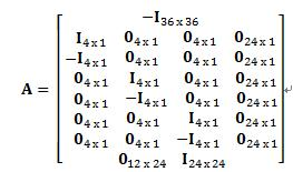
여기서, ![]()
![]()
![]()
![]()

여기서, 상기 ![]()
![]()
Where ![]()
![]()
최적화(OPTIMIZATION)OPTIMIZATION
상술한 파라미터에 따라 추정된 모델로부터 특정 ‘비용’ 목표(target) 및/또는 제약(constraint)을 만족하는 최적 전력 프로파일을 찾을 수 있다. 이 부분에서의 논의는 냉방에만 제한된다. 그러나, 난방과 관련하여도 비슷한 최적화 프로세스가 가능할 것이다.The optimal power profile that satisfies a particular 'cost' target and / or constraint may be found from the model estimated according to the above-described parameters. The discussion in this section is limited to cooling. However, similar optimization processes are possible with regard to heating.
예를 들어, ![]()
![]()
![]()
![]()
![]()
![]()
![]()
![]()
![]()
![]()
![]()
![]()
![]()
![]()
![]()
![]()
본 실시예의 에너지 소비의 금전적(dollar) 비용은 다음과 같이 주어진다.The dollar cost of energy consumption of this embodiment is given as follows.

여기서, ![]()
![]()
![]()
![]()

다음과 같이, 기결정된 목표 평균 쾌적성 수준(predetermined target average comfort level)으로부터의 편차(deviation)에 비용을 부과(impose)할 수도 있다.It may also impose a deviation from a predetermined target average comfort level as follows.

우리는 이러한 세 가지의 비용 성분을 하나의 단일 비용 함수로 묶을 수 있다.We can combine these three cost components into one single cost function.
![]()
![]()
수학식 35에서, 세 가지 파라미터 ![]()
![]()
![]()
![]()
![]()
![]()
비용 함수는 표준 최적화를 이용하여 최적의 전력 프로파일을 찾을 수 있게 한다. 물론, 변형 또는 변경된 비용 함수가 사용될 수도 있다.
The cost function makes it possible to find the optimal power profile using standard optimization. Of course, modified or modified cost functions may be used.
난방을 포함하는 변형 모델(ALTERNATIVE MODEL INCLUDING HEATING)ALTERNATIVE MODEL INCLUDING HEATING
난방 최적화를 포함하는 이전 모델의 확장(extension)의 일 형태가 이제부터 설명될 것이다. 상기 확장(extension)은 추가적인 건물 작동 타입, 난방 및 연료 자원 혼합 및 변형된 최적화, 모델링 방법들을 고려하는 것이다. 모델은 열 에너지, 전기 및 비전기 연료원, 냉난방 혼합 상황의 에너지 소비, 쾌적성 수준 및 건물의 CO2 배출의 영향을 규명하기 위해 확장될 수 있다. One form of extension of the previous model, including heating optimization, will now be described. The extension is to consider additional building operation types, heating and fuel resource mixing and modified optimization, modeling methods. The model can be extended to identify the effects of thermal energy, electric and non-electric fuel sources, energy consumption in a heating and cooling mix, comfort levels, and CO2 emissions from buildings.
변형 모델은 가스 보일러 난방 시스템, 가열 및 냉각된 물 루프(water loop) 및 VAV를 구비하는 건물에 대하여 시험되기 위해 설계된다. 물론, 주문제작된 어떠한 특정 건물도 수행될 수 있다. 모델이 개발된 건물예(example building)는 호주 빅토리아(Victoria, Austrailia)에 위치하였고, 다음의 특징을 가졌다. 건축: 블록작업(blockwork), 2006 완공, 바닥면적(floor area): 1808m2, 3층, 사무실, 작동: 혼합 모델(팬, 자동창문으로 자연환기), 난방: Raypak 868 가스 보일러(868kWth), 냉방: York YCA 0235 6-stage Air-Cooled Scroll Chiller(235kWth nominal), BMS: Siemens Desigo v3.0, Siemens BACNet Sever, 계량기(Metering): 가스 볼륨 계량, 전기 보조 계량(기계 서비스 & 건물 전체).The variant model is designed for testing on buildings with gas boiler heating systems, heated and cooled water loops and VAV. Of course, any particular building can be implemented. The example building in which the model was developed was located in Victoria, Austrailia, Australia. Construction: Blockwork, 2006 Completion, Floor Area: 1808m2, 3rd Floor, Office, Operation: Mixed Model (fan, natural ventilation with automatic windows), Heating: Raypak 868 Gas Boiler (868kWth), Air Conditioning : York YCA 0235 6-stage Air-Cooled Scroll Chiller (235kWth nominal), BMS: Siemens Desigo v3.0, Siemens BACNet Sever, Metering: Gas Volume Metering, Electric Auxiliary Metering (Mechanical Service & Building).
이 변형 모델은 존 온도에 대한 냉방 및 난방의 영향을 학습하기 위해 건물 에너지 모델의 구조를 확장하기 위해 제공된다. 또한 상기 모델은 냉방 및 난방 에너지 소비의 최적화를 고려한 것이다. 상기 모델은 비전기 연료원 또한 다룬다. 이는 용량(capacity), 가격 구조 및 온실가스 배출에 대한 고려(consideration)을 포함한다. 또한, 상기 모델은 복합(동시도 가능한) 에너지원의 취급도 고려하는 것이다. This variant model is provided to extend the structure of the building energy model to learn the effects of cooling and heating on zone temperatures. The model also takes into account optimization of cooling and heating energy consumption. The model also deals with non-electric fuel sources. This includes consideration of capacity, price structure and greenhouse gas emissions. The model also considers the handling of complex (simultaneous) energy sources.
냉방만을 다루는 종전 모델은 온화 기후의 건물을 위해 설계되어 HVAC 에너지 소비는 냉방에 의해 지배된다. 냉방은 대부분 전기 냉방장치를 사용하여만 달성되는 반면, 난방을 공급하는 것에는 일반적으로 몇몇의 다른 시스템 및 연료 종류가 사용된다. 또한, 복합적인 다른 시스템들이 설치될 수 있고, 한 건물에서 동시에 가동(현저하게 복잡한 실시)될 수 있다.Previous models dealing with cooling only are designed for buildings with mild climate, so HVAC energy consumption is dominated by cooling. Cooling is mostly achieved only by using electric cooling, whereas several different systems and fuel types are generally used to supply heating. In addition, multiple other systems can be installed and run simultaneously (a significantly complex implementation) in one building.
건물이 냉난방 복합 시스템을 구비하여 주어진 조건 하에서 어떠한 것을 사용할지 결정할 수 있는 실질적인 유연성을 가지더라도, 이 변형 모델에 사용되는 접근법은 기존의 BMS로 하여금 주어진 조건 설정점에 영향을 주기 위하여 사용되는 플랜트의 적절한 조합을 결정할 수 있게 하는 것이다. 고수준(high level)에서, 이 변형 모델은 에너지 온실가스와 건물 상태(condition) 사이의 관계를 학습하고, 최적화된 존 조건(condition) 설정점을 적용한다. 저수준(low level)에서, 이 변형 모델은, 핵심 최적화의 일부는 아니라고 하더라도, 가동을 중지하도록 사용되거나 특정 플랜트를 우선적으로 사용할 수 있다. 저수준 변화가 일어나면, 이 변형 모델은 조건(condition)/에너지 관계의 변화를 통해 이를 파악하고, 이에 맞게 건물 모델을 업데이트한다.
Although the building is equipped with a heating and cooling composite system with the practical flexibility to determine what to use under a given condition, the approach used in this transformation model allows existing BMSs to determine which plant is used to influence a given condition set point. To determine the appropriate combination. At the high level, this transformation model learns the relationship between energy greenhouse gases and building conditions and applies optimized zone condition set points. At a low level, this variant model can be used to shut down or preferentially use a specific plant, even if it is not part of the core optimization. When a low level change occurs, the transformation model identifies this through changes in the condition / energy relationship and updates the building model accordingly.
존 수준 난방/냉방 제어(ZONE LEVEL HEATING/COOLING CONTROL)ZONE LEVEL HEATING / COOLING CONTROL
주요 제어 변수(key control variable)에서의 존 수준 PMV를 사용하던 초기 논의 모델. 이 냉방 지배 케이스에서, 난방은 규칙 기반 접근법(rule based approach)(최소한의 수용 가능한 쾌적성 수준(그 이상은 아닌)으로의 열)을 이용하여 수행되었고, PMV 설정점은 냉방 목표 수준으로 해석되었다. 개별 존 제어 알고리즘은 필수적이었다. If TZone < TMin_Allowed then Heat_To_TMin else Cool_To_PMV_Setpoint end.Early discussion model using zone-level PMV at key control variable. In this cooling control case, heating was performed using a rule based approach (heat to the minimum acceptable comfort level, but not higher), and the PMV set point was interpreted as the cooling target level. . Individual zone control algorithms were essential. If T Zone <T Min_Allowed then Heat_To_T Min else Cool_To_PMV_Setpoint end.
정확히 어떻게 이러한 냉난방 설정점들이 설정되었는지는 구체적인 BMS 및 건물 구성(공기 공급 설정점, 냉각 및 가열 물 밸브 등의 제어를 포함하여)에 종속되었다. 중요한 것은 이러한 저수준 BMS 인터페이스는 에너지가 냉방 설정점 아래로 냉방하는데 낭비되지 않거나, 난방 설정점 위로 난방하는데 낭비되지 않는 것을 담보한다는 것이다. 예를 들어, 전기 재가열(electric reheats)은 냉방 전력을 감소시키려는 의도로 존 설정점을 높일 때 나타난다(come on). 냉방과 난방을 모두 최적화시키기 위해 (에너지 낭비가 심할 수 있는 인접한 존들에서) 냉방/난방이 동시에 일어날 가능성을 최소화하는 동안 변형 모델의 고수준 건물 최적화는 두 개의 설정점(냉방 설정점 PMV, 난방 설정점 PMV)을 생성하기 위하여 변경된다. 기본 개별 존 제어 알고리즘은 종전 것과 본질적으로 동일하지만 냉방과 난방 설정점이 모두 PMV로 표현되고 최적화에 따라 동역학적으로 변화하는 If PMVZone < PMVHeat_Setpoint then Heat_To_PMVHeat_Setpoint else Cool_To_PMVCool_Setpoint end를 반드시 실행하도록 변경된다. 이는 저수준 존 제어기에 최소한의 변화를 요구한다.Exactly how these air conditioning set points are set depends on the specific BMS and building configuration (including control of air supply set points, cooling and heating water valves, etc.). Importantly, this low-level BMS interface ensures that energy is not wasted to cool below the cooling set point or to heat above the heating set point. For example, electric reheats come on increasing the zone set point with the intention of reducing cooling power. The high-level building optimization of the deformation model provides two set points (cooling set point PMV, heating set point) while minimizing the possibility of simultaneous cooling / heating (in adjacent zones where energy waste can be significant) to optimize both cooling and heating. To generate PMV). The basic individual zone control algorithm is essentially the same as before, but if the cooling and heating set points are both expressed in PMV and dynamically changed by optimization, then PMV Zone <PMV Heat_Setpoint then Heat_To_PMV Heat_Setpoint else Cool_To_PMV Cool_Setpoint end must be changed. This requires minimal change in the low level zone controller.
난방, 냉방 및 여러 연료원을 포함시키는 것을 수월하게 하기 위해, ‘그레이 박스(grey box)’ 건물 모델의 구조가 수정된다. 업데이트된 공식은 다음과 같다.To facilitate heating, cooling, and the inclusion of multiple fuel sources, the structure of the "grey box" building model is modified. The updated formula is:
![]()
![]()
여기서, ![]()
![]()
![]()
![]()
![]()
![]()
![]()
![]()
![]()
![]()
![]()
![]()
![]()
![]()
을 (모델링된) 프리러닝(free-running) 존 온도(즉, HVAC 시스템이 가동하지 않을 때의 애그리게이트 존 온도의 추정치)로,Is the (modeled) free-running zone temperature (ie, an estimate of the aggregate zone temperature when the HVAC system is not running),
![]()
![]()
을 HVAC 시스템에 따른 존 온도의 차이로 명시한다.Is specified as the difference in zone temperature for the HVAC system.
필터 F(s)는 피드스루(feed-through) 및 1, 2, 5시간에서의 시정수와 함께 3차 오더 LTI였고, 또 그렇게 남는다. 구체적으로,Filter F (s) was, and remains, 3rd order LTI with feed-through and time constants at 1, 2, and 5 hours. Specifically,

및And

여기서, ![]()
![]()
![]()
![]()
![]()
![]()
![]()
![]()
![]()
![]()
![]()
![]()
![]()
![]()
난방/냉방 전력 관계(Heating/Cooling Power Relationships)Heating / Cooling Power Relationships
종전 모델은 냉방 지배적 방식을 목표로 한 반면, 난방 방식을 다루려면 변형된 전력 모델이 요구된다. 주요 인자로, 존 사이의 다이버시티(diversity)는 애그리게이트 존 온도가 설정점에 있더라도 난방 및 냉방을 인가된 HVAC 전력에 비례하도록 취급하는 것이 아닌, 난방 및 냉방 에너지 모두가 개별 존을 설정점에 있도록 유지하는데 사용될 필요가 있음을 의미한다. 주목할만한(notable) 냉방/난방이 달성되기 전이라도 가동되는, HVAC 시스템과 관련된, 합리적으로(reasonably) 고정된 몇몇의 로드(load)(즉, 팬&펌프)가 필요하다. 이러한 베이스라인의 일부는 다른 사이트 로드(site load)에 기인할 수도 있다. 다른 인자는 주위 온도에 따라 변하는 냉난방 시스템의 효율이다. 특정 예로, 주위 온도가 상승하면 COP(coefficient of performance)가 감소한다. 난방장치/냉방장치(데이퍼지(day-purge))를 우선적으로 가동하기 위한 증가된 외부 공기의 사용 역시 이러한 영향(impact)이 있다.Conventional models are aimed at the cooling dominant method, while a modified power model is required to deal with the heating method. As a major factor, the diversity between zones does not treat heating and cooling proportional to the applied HVAC power, even when the aggregate zone temperature is at the set point, but both heating and cooling energy is associated with the individual zone at the set point. It needs to be used to keep it. There is a need for some reasonably fixed loads (i.e. fans & pumps) associated with HVAC systems that operate even before notable cooling / heating is achieved. Some of these baselines may be due to other site loads. Another factor is the efficiency of the heating and cooling system, which varies with ambient temperature. As a specific example, as the ambient temperature rises, the coefficient of performance decreases. The use of increased external air to prioritize heating / cooling (day-purge) also has this effect.
측정된 전력과 애그리게이트 존 온도에의 영향 사이의 관계로 다음이 사용되었다.The following was used as a relationship between the measured power and the influence on the aggregate zone temperature.
![]()
![]()
여기서, 상기 수학식의 첫 번째 부분은 유효냉방온도(effective cooling temperature,![]()
![]()
![]()
![]()
![]()
![]()
![]()
![]()
![]()
![]()
![]()
![]()
![]()
![]()
![]()
![]()
![]()
![]()
![]()
![]()
디레이팅은 다음과 같이 파라미터화된다.Derating is parameterized as follows.
![]()
![]()
및And
![]()
![]()
![]()
![]()
![]()
![]()
![]()
![]()
![]()
![]()
또한, 난방/냉방 복합 시나리오를 에뮬레이팅(emulate)하기 위해, 유효냉방은 ![]()
![]()
![]()
![]()
![]()
![]()
![]()
![]()
![]()
![]()
도 12는 이러한 변수들의 상호관계를 나타낸다. 결합된 냉난방 전력은 ‘V’ 또는 포물선 종류의 관계를 만족하는 건물의 총 전력을 도출하여, 우리는 건물의 전력을 외부 온도의 함수로 예상한다.
12 illustrates the interrelationship of these variables. The combined heating and cooling power yields the total power of the building that satisfies the relationship of the 'V' or parabolic type, so we estimate the power of the building as a function of outside temperature.
수정된 건물 모델로의 피팅(Fitting to the Revised Building Model)Fitting to the revised building model
수정된 모델에서, 건물 모델의 피팅은 시스템이 재가동되면서 하루에 한 번 수행된다. 건물 로그 파일(log file)로부터 데이터가 읽히고, 신호를 위하여 시계열 데이터가 추출된다. 이러한 데이터는 ![]()
![]()
![]()
![]()
![]()
![]()
![]()
![]()
이상적으로는 이들 데이터 세트는 2-3개월의 연속적인 데이터를 포함해야 한다. 이러한 경우가 아니라면, 작은 데이터 갭(gap)은 보간(interpolate)될 수 있다. 데이터 갭이 크다면, 데이터는 여러 세트로 분해(break up)될 수 있고, 데이터가 필터링되면 각 세트의 처음 5시간은 알려지지 않은 초기 조건의 영향을 최소화하기 위해 버려진다.Ideally, these data sets should contain 2-3 months of continuous data. If this is not the case, small data gaps can be interpolated. If the data gap is large, the data can be broken up into several sets, and once the data is filtered, the first five hours of each set are discarded to minimize the impact of unknown initial conditions.
모델 피팅 평가는 2-노름(2-norm)을 근거로 한다. 즉, 
모델 피팅은 중첩된 최적화(nested optimization)로 프로그램화될 수 있다.Model fitting can be programmed with nested optimization.
![]()
![]()
여기서, 전력 파라미터는 ![]()
![]()
![]()
![]()
![]()
![]()
![]()
![]()
![]()
![]()
![]()
![]()
![]()
![]()
![]()
![]()
![]()
![]()
![]()
![]()
![]()
![]()
![]()
![]()
![]()
![]()
![]()
![]()
![]()
![]()
![]()
![]()
![]()
![]()
![]()
![]()
이러한 모델 피팅을 실시하는데 있어서, Matlab lsqlin 함수(least squares with linear constraints)가 필터 파라미터를 피팅하기 위해 사용될 수 있고, fmincon(multidimensional constrained nonlinear minimization)이 전력 파라미터를 검색(search)하기 위해 사용될 수 있다. 모델은 요구되는 비선형 최소화(nonlinear minimization)의 크기를 감소시키기 위해 이러한 방법으로 분해(break up)된다. 이는 선형 케이스보다 더 어려운 문제이다. 모델 피팅 루틴(routine)은 업데이트되기 때문에, 파라미터 값의 한계는 상기 루틴에 하드코딩(hard coded)되는 것 보다는, 각 파라미터의 상계 및 하계(upper and lower bounds)로 패스인(pass in)한다. 파라미터가 피팅되지 않으면, 이들 상계 및 하계는 동일하게 설정된다.
In performing this model fitting, Matlab lsqlin functions (least squares with linear constraints) can be used to fit the filter parameters , and fmincon (multidimensional constrained nonlinear minimization) can be used to search for power parameters . The model is broken up in this way to reduce the amount of nonlinear minimization required. This is a more difficult problem than a linear case. Because the model fitting routine is updated, the limits of parameter values pass in to the upper and lower bounds of each parameter, rather than being hard coded into the routine. If the parameters are not fitted, these upper and lower bounds are set equally.
수정된 건물 모델과 함께 건물 설정점 최적화(Optimising Building Setpoints with the Revised Building Model)Optimizing Building Setpoints with the Revised Building Model
변형 모델에서, 건물 설정점 최적화를 위한 방법론은 난방 방식을 고려하기 위하여 수정될 수 있다. 종전에는, 최적화는 최적화된 전력 프로파일을 되돌려주고, 이 전력 프로파일은 트래킹(tracking)되면서 각 존을 위한 적절한 PMV 설정점을 결정하도록 사용되었다. 변형 모델에서는, 수정된 최적화는 예상 난방 및 냉방 전력에 더하여 듀얼(dual) 난방 및 냉방 목표 PMV 설정점을 분명하게 제공한다. 상기 PMV 설정점은 이제 주요 최적화 설정점으로 취급되고, 예상 전력 사용이 초과될 때에만 릴랙스(relax)된다. 이러한, 초기 조건 계산으로의 수정된 접근은 전력 측정에 있어서의 변동(fluctuation)에 대한 민감성의 일부를 극복하는데 도움을 준다(예상 전력 사용이 초과되지 않으면, 건물은 PMV 설정점에 대하여 작동할 것이다).In the deformation model, the methodology for optimizing building set points can be modified to take account of the heating scheme. Previously, optimizations returned an optimized power profile, which was tracked and used to determine the appropriate PMV set point for each zone. In the variant model, the modified optimization clearly provides dual heating and cooling target PMV set points in addition to the expected heating and cooling power. The PMV set point is now treated as a major optimization set point and is only relaxed when the expected power usage is exceeded. This modified approach to initial condition calculation helps to overcome some of the susceptibility to fluctuations in power measurements (if the estimated power usage is not exceeded, the building will operate against the PMV set point). ).
듀얼 PMV 설정점은 종전과 비슷한 최적화 프로세스를 통해 유도되나, 이제는 냉방전력이 아니라 ![]()
![]()
![]()
![]()

즉, 건물이 애그리게이트(aggregate) 난방이 될 때, 냉방이 필요한 존은 오직 최소 수용 가능 PMV(PMV 스케일(scale)은 -3(cold)에서 3(hot)으로 변함)로 냉방되고, 난방되는 존은 최적화 PMV 설정점을 목표로 한다. 냉방 모드를 위해서도 유사한 공식이 사용될 수 있다.That is, when a building becomes aggregate heating, the zones that require cooling are only cooled to the minimum acceptable PMV (PMV scale varies from -3 (cold) to 3 (hot)) and heated. Zone targets the optimized PMV set point. Similar formulas can be used for the cooling mode.
설정점 최적화는 실제 건물 존 온도, 에너지 가격 및 일기예보의 업데이트된 정보를 근거로 하여 매 5분 마다 가동된다. 이들은 냉난방 전력과 건물 열적 상태 사이의 예상 관계를 도출하는 종전에 결정된 건물 모델과 함께 사용된다. Setpoint optimization is enabled every 5 minutes based on updated information on actual building zone temperatures, energy prices and weather forecasts. They are used in conjunction with previously determined building models to derive the expected relationship between heating and cooling power and building thermal conditions.
![]()
![]()
최적화는Optimization is
![]()
![]()
를 최소화하려고 한다. 여기서, ![]()
![]()
![]()
![]()
![]()
![]()
![]()
![]()
![]()
![]()
이러한 비용 함수를 평가하는데 있어서, ![]()
![]()
![]()
![]()
In evaluating these cost functions, ![]()
![]()
![]()
![]()
초기 조건의 취급(Dealing with Initial Conditions)Dealing with Initial Conditions
종전 모델은 모델 다이내믹스(dynamics)를 초기 설정하기 위해 냉방 전력 및 주위 온도의 측정치에 의존하였다. 이는 측정된 전력이 예상 모델링 전력과 크게 다르거나(예를 들어, 압축기 스테이징(staging)으로 인해), 건물 다이내믹스 및 로드(사용 패턴)가 모델링된 것과 크게 다른 경우에는 문제를 야기할 수 있다. 이는 (현재 시간까지의) 측정된 거동과 앞으로의 예상 거동 사이의 불연속으로 명백해질 수 있다. 이를 극복하기 위해 돕고, 전력 모델링에 대한 의존도를 최대한 제거하기 위해 최적화는 상태(state) ‘추정기(estimator)’(관측기(observer))를 사용하여 건물의 동역학적 상태를 모델링할 수 있다(그리고 프리러닝 응답을 제공한다.). 이는 최적화 루틴이 제안된 ![]()
![]()
추정된 조건(conditioning)은 건물 모델을 시간 tnow 에 이르기까지 재배열하는 것에 의해 얻어진다.Estimated conditioning is obtained by rearranging the building model up to time t now .
![]()
![]()
그리고 프리러닝(free-running) 건물 응답(no HVAC)은 tnow 보다 큰 시간에서 ![]()
![]()
![]()
![]()
을 계산하는 것에 의하여 얻어지며, 제어된 건물 애그리게이트 존 온도 응답은 다음과 같이 주어진다.And the controlled building aggregate zone temperature response is given by
![]()
![]()
![]()
![]()
여기서, ![]()
here, ![]()
다른 종류의 연료 공급(Catering for different Fuel Types)Catering for different Fuel Types
변형 모델은 다른 종류의 연료 또한 취급할 수 있다. 여기서의 주요 이슈는 다른 연료 종류는 다른 온실가스 포텐셜(potential)을 가지고 있다는 점, 다른 연료 종류는 다른 가격 구조를 가진다는 점, 연료 사용을 모니터링 하기 위해 다른 측정 방법이 사용되는 점이다. Modified models can also handle other types of fuels. The main issue here is that different fuel types have different greenhouse gas potentials, different fuel types have different price structures, and different measurement methods are used to monitor fuel usage.
호주에서는, 호주 정부에 의해 서로 다른 에너지원의 상대적 영향이 계산된다(Department of Climate Change and Energy Efficiency (DCCEE)). 이러한 수치는 매년 업데이트되고 NGA 인자(National Greenhouse Accounts Factors)로 출판된다. 상기 인자는 다른 채취 방법, 연료 혼합, 배전 손실(distribution loss) 등에 따라 변화하고, 그 결과 시간 및 지리적 위치에 따라 변화한다. 온실가스 영향에 대한 보고에서, 세 가지의 다른 종류의 배출 인자가 사용되었다. 직접배출(Scope 1) - 이는 활동(activity)으로부터의 직접적인 CO2 등가물 배출이다(예를 들어, 천연가스 연소 과정에서 직접적으로 방출되는 CO2). 간접배출(Scope 2) - 이는 전기 생성 과정으로부터의, 조직(organization)에 의해 구매되고 소비되는, 활동을 하기 위한, 간접적인 CO2등가물 배출이다. 기타 간접배출(Scope 3) - 이는 연료의 추출, 생산, 운송, 발생, 배분/이송 등에 관련된 다양한 추가적 배출이다. 이는 전력망 손실도 포함한다. 완전한 연료 사이클의 평가 비용은 기타 간접배출에 포함된다.In Australia, the relative impact of different energy sources is calculated by the Australian Government (Department of Climate Change and Energy Efficiency (DCCEE)). These figures are updated annually and published as National Greenhouse Accounts Factors. The factors change with different sampling methods, fuel mixes, distribution losses, and the like, and consequently with time and geographic location. In reporting on greenhouse gas impacts, three different kinds of emission factors were used. Direct emissions (Scope 1) -This is the direct CO 2 equivalent emissions from activity (eg CO 2 emitted directly during natural gas combustion). Indirect Emissions (Scope 2) -These are indirect CO 2 equivalent emissions for activities to be purchased and consumed by the organization from the electricity generation process. Other indirect emissions (Scope 3)-These are various additional emissions related to the extraction, production, transportation, generation, distribution / transportation of fuels. This includes grid losses. The cost of evaluating the complete fuel cycle is included in other indirect emissions.
상업 건물 부문에서는 다른 연료 종류의 상대적 비율이 사용되고, 호주 상업 건물에 사용된 다른 연료 종류의 상대적 비율에 대한 보고는 아래의 도 14에 도시되었다. (놀랍지 않게도) 전기와 천연가스의 사용이 지배적이다. 호주에서의 이들 연료의 완전한 연료 사이클의 가장 최근의 추정치(July 2010, from [1])는 아래의 표에 정리되어 있다(1MWh=3.6GJ).The relative proportions of other fuel types are used in the commercial building sector, and a report on the relative proportions of other fuel types used in Australian commercial buildings is shown in FIG. 14 below. (Unsurprisingly) the use of electricity and natural gas dominates. The most recent estimate of the complete fuel cycle of these fuels in Australia (July 2010, from [1]) is summarized in the table below (1 MWh = 3.6 GJ).
kgCO2-e/GJkgCO 2 -e / GJ
kgCO2-e/GJ (kgCO2-e/kWh)kgCO 2 -e / GJ (kgCO2-e / kWh)
다른 종류의 연료 공급 및 측정 방법의 설정 변화(Configuration Changes to Cater for Different Fuel Types and Measurement Method)Configuration Changes to Cater for Different Fuel Types and Measurement Method
종전 모델은 오직 한 가지 타입의 전력 측정(냉방에 기여하는 전기 kW)만을 효과적으로 다루었다. 변형 모델에서는, 설정(configuration) 파라미터를 포함시키는 것에 의해 업데이트된다.Previous models effectively handled only one type of power measurement (electrical kW, which contributes to cooling). In a variant model, it is updated by including configuration parameters.
변형 모델은 5개의 설정 변수를 포함한다.The deformation model includes five configuration variables.
Config_PowerWeights 1 0.72 278
Config_CarbonWeights 1.07 1.07 0.236Config_CarbonWeights 1.07 1.07 0.236
Config_PowerTypes CP CP HEConfig_PowerTypes CP CP HE
Config_PowerPrices 1 1 2
Config_PowerPriceNames ‘Elec TOU’‘Gas’Config_PowerPriceNames ‘Elec TOU’’Gas’
많은 종류의 정규화(normalization)가 사용될 수 있지만, 조정 인자는 서로 다른 연료 및 측정 타입의 상대적 영향을 비교하기 위한 메커니즘을 제공할 필요가 있다. 조정 인자는 전력을 비교하기 위하여 kW(또는 kWh)로, 온실가스 영향을 비교하기 위하여 kgCO2-e/kWh로 측정된 양을 변환하는 것으로 명목적으로 고려되어 왔다. PowerWeights 설정 변수는 kW(또는 kWh)로 조정(scale)한다. CarbonWeights 변수는 kgCO2-e로 조정한다. PowerTypes 변수는 각 전력 측정을 분류하여 냉방(C) 또는 난방(H)으로 부여(contribute)하고, 전력(P) 또는 에너지(E) 측정 타입으로 부여한다. 전력 측정은 (예를 들어) 직접적인 kW 측정이다. 에너지 측정은 누적계(cumulative register)(즉, kWh)를 통하고, 반드시 시간에 대해 미분되어 전력 수준을 결정한다. 전력타입으로 가능한 값은 ‘CP’, ‘CE’, ‘HP’ 및 ‘HE’이다. PowerPriceNames은 서로 다른 에너지 가격 구성의 이름을 홀딩한다. PowerPrices는 어떤 에너지 가격 구조가 각 전력 측정에 적용될 것인지를 결정하기 위해 PowerPriceNames에게 인덱스(index)를 제공한다. Many kinds of normalization can be used, but the adjustment factors need to provide a mechanism for comparing the relative effects of different fuels and measurement types. The adjustment factor has been nominally considered to convert measured quantities to kW (or kWh) to compare power and to kgCO 2 -e / kWh to compare greenhouse gas effects. The PowerWeights configuration variable scales to kW (or kWh). The CarbonWeights variable is adjusted to kgCO 2 -e. The PowerTypes variable classifies each power measurement and contributes it to cooling (C) or heating (H), and gives it to the power (P) or energy (E) measurement type. Power measurements are direct kW measurements (for example). Energy measurements are made through cumulative registers (ie, kWh) and must be differentiated over time to determine power levels. Possible values for the power type are 'CP', 'CE', 'HP' and 'HE'. PowerPriceNames hold the names of different energy price schemes. PowerPrices provides an index to PowerPriceNames to determine which energy price structure will apply to each power measurement.
상기 예의 특정 설정 값에서, 3개의 측정된 전력 데이터 포인트가 있다. 이들은 건물 설정 파일에서 전력_1, 전력_2 및 전력_3으로 명명될 것이다. 전력_1은 직접적으로 kW로 측정되므로 PowerWeights는 1이다. CO2-e로의 조정 인자(scaling factor)는 1.07(for NSW)이다. 이 에너지는 ‘CP’로 직접적으로 측정되는 전력과 함께 냉방에 사용된다. 에너지 가격 타입은 ‘Elec TOU’이고, 따라서 인덱스 1이 PowerPriceNames에 주어진다. 전력_2는 3상 대칭 시스템(balanced 3 phase system)의 1상(1 phase)의 암페어(amps)를 측정함으로써 얻어진다. 따라서 측정된 1 암페어는 720W 전력에 대응하므로 PowerWeights는 0.72로 주어진다. 다른 조정 인자는 전력_1과 같다. 전력_3은 난방을 위한 가스이다. 이것은 GJ 단위의 어큐뮬레이션 미터(accumulation meter)를 이용하여 측정된다. 278의 PowerWeights는 GJ를 등가의 kWh로 변환한다. 0.236의 CarbonWeights는 천연가스 소비의 1 kWh 등가물과 동일시되는 kgCO2-e이다. PowerPrice는 가스 가격 구조의 PowerPriceNames 에 부여되는 인덱스인 2이다. At the specific setpoint in the above example, there are three measured power data points. These will be named power_1, power_2 and power_3 in the building configuration file. _1 power is therefore directly measured as kW is
다양한 전력 가격 구조의 이름이 설정 파일에 저장되나, 가격 수준의 실제 설정은 다양한 연료 종류(EnergyPriceConfigV2.m 참조)를 고려하기 위해 업데이트되는 ‘에너지 가격 설정(Energy pricing Configuration)’ GUI를 통해 수행된다. 이는 TOU 가격 구조로 하여금 각 연료 종류(가스와 같이 일정 가격으로 고정될 수 있는)를 준비(set for)할 수 있게 한다. 도 15는 데이터 입력을 위한 업데이트된 GUI를 도시한 것이다. 단위는 명목적으로 c/kWh가 사용되었으나, 물론 이는 임의적인 것이다.
The names of the various power price structures are stored in the configuration file, but the actual setting of the price level is done through the 'Energy pricing Configuration' GUI, which is updated to take into account the various fuel types (see EnergyPriceConfigV2.m). This allows the TOU price structure to set for each fuel type (which can be fixed at a fixed price, such as gas). 15 shows an updated GUI for data entry. The unit is nominally c / kWh used, but of course this is arbitrary.
참고문헌(References)References
Australian Greenhouse Office (1999), Australian Commercial Building Sector Greenhouse Gas Emissions 1990-2010. Available online at http://www.environment.gov.au/ [Accessed 17 June 2008] Australian Greenhouse Office (1999), Australian Commercial Building Sector Greenhouse Gas Emissions 1990-2010. Available online at http://www.environment.gov.au/ [Accessed 17 June 2008]
Braun, J.E. (1990), Reducing Energy Costs and Peak Electrical Demand Through Optimal Control of Building Thermal Storage, ASHRAE Trans. Vol 96(2), pp. 876-888 Braun, J.E. (1990), Reducing Energy Costs and Peak Electrical Demand Through Optimal Control of Building Thermal Storage, ASHRAE Trans. Vol 96 (2), pp. 876-888
Braun, J.E., Montgomery, K.W. and Chaturvedi, N. (2001), Evaluating the performance of building thermal mass control strategies. HVAC&R Research. Vol 7(4) pp 403-428. Braun, J.E., Montgomery, K.W. and Chaturvedi, N. (2001), Evaluating the performance of building thermal mass control strategies. HVAC & R Research. Vol 7 (4) pp 403-428.
Eto, J. (2007), Demand Response Spinning Reserve Demonstration. Ernest Orlando Lawrence Berkeley National Laboratory. Berkeley CA, USA. http://eetd.lbl.gov/ea/EMS/EMS_pubs.html [Accessed 17 June 2008] Eto, J. (2007), Demand Response Spinning Reserve Demonstration. Ernest Orlando Lawrence Berkeley National Laboratory. Berkeley CA, USA. http://eetd.lbl.gov/ea/EMS/EMS_pubs.html [Accessed 17 June 2008]
Fanger, P.O. (1967), Calculation of thermal comfort: introduction of a basic comfort equation. ASHRAE Transactions 73(2):III.4.1. Fanger, P.O. (1967), Calculation of thermal comfort: introduction of a basic comfort equation. ASHRAE Transactions 73 (2): III.4.1.
Seppanen, O., Fisk, W.J. and Lei, Q.H. (2006), Room temperature and productivity in office work, Lawrence Berkeley National Laboratory, University of California. http://repositories.cdlib.org/lbnl/LBNL-60952 [Accessed 17 June 2008] Seppanen, O., Fisk, W.J. and Lei, Q.H. (2006), Room temperature and productivity in office work, Lawrence Berkeley National Laboratory, University of California. http://repositories.cdlib.org/lbnl/LBNL-60952 [Accessed 17 June 2008]
White, S. and Ward, J.K. (2006), Performance of a Microturbine Power and Desiccant Cooling Demonstration. IIR-IRHACE International Conference 2006. Auckland, New Zealand. 16th - 18th Feb 2006. White, S. and Ward, J.K. (2006), Performance of a Microturbine Power and Desiccant Cooling Demonstration. IIR-IRHACE International Conference 2006. Auckland, New Zealand. 16th-18th Feb 2006.
Burress, C. (2008), State abandons plan to allow utilities to control home thermostats, San Francisco Chronicle, Jan 17 2008. [Online]. Available: http://www.sfgate.com [Accessed May 1, 2008]. Burress, C. (2008), State abandons plan to allow utilities to control home thermostats, San Francisco Chronicle,
Australian Government Department of Climate Change (2008), National Greenhouse Accounts (NGA) Factors. http://www.climatechange.gov.au [Accessed 17 June 2008] Australian Government Department of Climate Change (2008), National Greenhouse Accounts (NGA) Factors. http://www.climatechange.gov.au [Accessed 17 June 2008]
ASHRAE (2004), ANSI/ASHRAE Standard 55-2004, Thermal Environmental Conditions for Human Occupancy. American Society of Heating, Refrigerating and Air-Conditioning Engineers. Atlanta, USA. ASHRAE (2004), ANSI / ASHRAE Standard 55-2004, Thermal Environmental Conditions for Human Occupancy. American Society of Heating, Refrigerating and Air-Conditioning Engineers. Atlanta, USA.
Brager, G., Paliaga, G. and de Dear, R.J. (2004), Operable windows, personal control and occupant comfort. ASHRAE Trans., Vol. 110(2), pp.17-35. Brager, G., Paliaga, G. and de Dear, R.J. (2004), Operable windows, personal control and occupant comfort. ASHRAE Trans., Vol. 110 (2), pp. 17-35.
Seppanen, O., Fisk, W.J. and Faulkner, D. (2003), Cost benefit analysis of the night-time ventilative cooling. Proceedings of the Healthy Buildings 2003 Conference. Singapore 2003, Vol 3 pp 394-399. Seppanen, O., Fisk, W.J. and Faulkner, D. (2003), Cost benefit analysis of the night-time ventilative cooling. Proceedings of the Healthy Buildings 2003 Conference. Singapore 2003,
National Greenhouse Accounts (NGA) Factors. Department of Climate Change and Energy Efficiency, Commonwealth of Australia 2010. ISBN: 978-1-921299-04-9
National Greenhouse Accounts (NGA) Factors. Department of Climate Change and Energy Efficiency, Commonwealth of Australia 2010.ISBN: 978-1-921299-04-9
해석Translate (Interpretation)(Interpretation)
본 명세서의 “일실시예”는 그 실시예와 관련되어 설명되는 특정 특징, 구조 또는 특성이 본 발명의 적어도 하나의 실시예에 포함된다는 의미이다. 따라서, 본 명세서의 여러 곳에서의 “일실시예에서” 라는 어구는 반드시 동일한 실시예를 언급하는 것이 아니나, 그럴 수도 있다. 또한, 특정 특징, 구조 또는 특성은 하나 또는 그 이상의 실시예에서 어떠한 적당한 방법으로 결합될 수 있고, 이는 해당분야의 통상의 기술자에게는 자명할 것이다.“One embodiment” herein means that a particular feature, structure, or characteristic described in connection with the embodiment is included in at least one embodiment of the present invention. Thus, the phrases “in one embodiment” in various places in the specification are not necessarily all referring to the same embodiment, but may. In addition, certain features, structures, or characteristics may be combined in any suitable manner in one or more embodiments, as will be apparent to those skilled in the art.
비슷하게, 상술한 본 발명의 대표적인 실시예의 설명에서, 본 발명의 여러 특징들은 본 공개를 능률적으로 하고, 하나 또는 그 이상의 여러 창의적인 측면에 대한 이해를 돕기 위한 목적으로 때때로 하나의 실시예에 묶여서 설명되었다. 그러나, 이러한 공개 방법은 청구된 발명이 각 청구항에 명시된 것보다 많은 특징을 요구하는 의도를 반영한 것으로 해석되어서는 안 된다. 그것보다는, 아래의 청구항이 반영한 바와 같이, 창의적 측면은 상술한 공개된 하나의 실시예의 모든 특징보다 적은 특징을 요구한다. 따라서, “발명을 실시하기 위한 구체적인 내용” 아래의 특허청구범위는 본 발명의 분리된 각 실시예와 같이 그것 고유의 특징에 의거하고 있어 “발명을 실시하기 위한 구체적인 내용”에 명백하게 포함된다.Similarly, in the foregoing description of representative embodiments of the present invention, various features of the invention have been described in some instances, sometimes with the purpose of streamlining the disclosure and aiding in understanding one or more of the various creative aspects. . However, such disclosure should not be construed as reflecting the intention of the claimed invention to require more features than those specified in each claim. Rather, as the following claims reflect, inventive aspects require fewer features than all features of one disclosed embodiment described above. Accordingly, the claims below "Specific Contents for Invention" are based on their own characteristics as in separate embodiments of the present invention and are thus explicitly included in the "Specific Contents for Implementing the Invention".
또한, 상술한 실시예 중 일부는 다른 실시예가 포함하는 특징을 포함하지 않고 있으나, 통상의 기술자로서는 서로 다른 실시예의 특징들의 조합은 모두 본 발명의 범위에 속하는 것이고, 또 다른 실시예를 형성하는 것이라고 인식할 것이다. 예를 들어, 아래의 특허청구범위에서, 청구된 어떠한 실시예는 어떠한 조합으로도 사용될 수 있다.In addition, some of the above-described embodiments do not include the features included in other embodiments, but those skilled in the art that all combinations of features of different embodiments are within the scope of the present invention, and form another embodiment. Will recognize. For example, in the claims below, any embodiment claimed may be used in any combination.
또한, 상술한 실시예 중 일부는 컴퓨터 시스템의 프로세서 또는 다른 기능 수행 수단에 의해 실시될 수 있는 방법 또는 방법 구성요소의 조합으로 설명된다. 따라서, 그러한 방법 또는 방법 구성요소를 수행하기 위한 필요한 지시를 구비하는 프로세서는 상기 방법 또는 방법 구성요소를 수행하기 위한 수단을 형성한다. 또한, 상술한 장치 실시예의 구성요소는 본 발명을 실시하기 위한 목적으로 구성요소에 의해 수행되는 수단의 일 예이다.In addition, some of the above-described embodiments are described as methods or combinations of method components that may be implemented by a processor or other function performing means of the computer system. Thus, a processor having the necessary instructions to perform such a method or method component forms the means for performing the method or method component. In addition, the components of the above-described apparatus embodiments are examples of means performed by the components for the purpose of practicing the present invention.
제공된 설명에서, 많은 특정 상세 사항이 개시된다. 그러나, 본 발명의 실시예들은 그러한 특정 상세 사항이 없이도 실시될 수 있다. 다른 예, 공지 방법, 구조 및 기술은 본 설명에 대한 이해를 불명료하게 하지 않기 위해 자세히 설명되지 않았다.In the description provided, many specific details are set forth. However, embodiments of the invention may be practiced without such specific details. Other examples, well-known methods, structures, and techniques have not been described in detail in order not to obscure the understanding of this description.
“첫째”, “둘째”, “셋째” 등의 통상적인 형용사들은 단지 유사 물체들을 가리키기 위한 것이지, 반드시 그러한 순서, 시공간적 순위 등으로만 존재해야 하는 것은 아니다.Common adjectives such as “first,” “second,” and “third,” are only meant to refer to analogous objects, but do not necessarily exist in such order, space-time order, and so on.
특허청구범위에서, ‘포함하는’이라는 용어는 적어도 이어지는 구성요소/특징을 포함한다는 개방적인 용어이지, 다른 것들을 배제하는 것은 아니다. 따라서, ‘포함하는’이라는 청구항에 사용된 용어는 열거된 수단 또는 구성요소 또는 단계를 한정하는 것으로 해석되어서는 안 된다. 예를 들어, A 및 B를 포함하는 장치는 오직 A 및 B를 포함하는 장치로 한정되어서는 안 된다. In the claims, the term 'comprising' is an open term that includes at least the following components / features, but does not exclude others. Accordingly, the terms used in the claims, including, should not be construed as limiting the listed means or components or steps. For example, a device comprising A and B should not be limited to a device containing only A and B.
비슷하게, 특허청구범위에서 사용되는 ‘결합된’이라는 용어는 직접적인 결합으로 제한 해석되어서는 안 된다. ‘결합된’ 및 ‘연결된’이라는 용어와 이들로부터 파생된 용어가 사용될 수 있다. 이러한 용어들은 서로 동의어라고 해석되어서는 안 된다. 따라서, 장치 A가 장치 B에 결합된다는 표현은 장치 A가 직접적으로 장치 B에 연결되는 것이라고 제한 해석 되어서는 안 된다. 즉, A와 B 사이에는 다른 장치 또는 수단이 있을 수 있다. “결합된”이라는 용어는 2 이상의 구성요소가 직접적으로 물리적으로 결합되거나 전기적 접촉을 하는 것일 수 있고, 또는 서로 직접적인 접촉은 하지 않으나 서로 상호작용을 하는 것일 수 있다.Similarly, the term "coupled" as used in the claims should not be construed as limited to direct combination. The terms "coupled" and "connected" and terms derived therefrom may be used. These terms should not be interpreted as synonyms for each other. Thus, the expression that device A is coupled to device B should not be construed as limiting that device A is directly connected to device B. That is, there may be other devices or means between A and B. The term "coupled" may mean that two or more components are in direct physical coupling or electrical contact, or they may be in direct contact with each other without direct contact with each other.
본 발명은 바람직한 특정 실시예를 참조하여 설명되었으나, 아래의 특허청구범위의 범위 및 사상 내에서 다양한 변형 및 변경이 있을 수 있다.Although the present invention has been described with reference to specific preferred embodiments, various modifications and changes can be made within the scope and spirit of the following claims.
Claims (29)
(b) 상기 건물을 위한 일일 난방(heating), 환기(ventilation) 및 공기조화(air conditioning)(HVAC) 작동 계획을 지속적으로 개발하기 위해 상기 열적 모델을 이용하는 단계; 및
(c) 현재 HVAC 작동 계획을 지속적으로 점검하고 상기 현재 HVAC 작동의 얼라인먼트를 상기 현재 HVAC 작동 계획으로 최적화하는 단계;
를 포함하는 건물의 HVAC 시스템 제어 방법.(a) developing an initial thermal model of the building and continuously updating the thermal model over time;
(b) using the thermal model to continuously develop daily heating, ventilation and air conditioning (HVAC) operating plans for the building; And
(c) continuously checking a current HVAC operation plan and optimizing the alignment of the current HVAC operation with the current HVAC operation plan;
HVAC system control method of a building comprising a.
상기 열적 모델은 상기 건물의 이력 열적 데이터에 피팅된 일련의 파라미터를 사용하는 건물의 HVAC 시스템 제어 방법.The method of claim 1,
Wherein the thermal model uses a series of parameters fitted to the historical thermal data of the building.
상기 열적 모델은 구간적 다항식 모델인 건물의 HVAC 시스템 제어 방법.The method of claim 1,
The thermal model is a sectional polynomial model.
상기 초기 열적 모델은 실질적으로 매일 반복적으로 업데이트되는 건물의 HVAC 시스템 제어 방법.The method of claim 1,
Wherein the initial thermal model is updated substantially daily repeatedly.
상기 일일 HVAC 작동 계획은 실질적으로 매 5분 마다 다시 계산되는 건물의 HVAC 시스템 제어 방법.5. The method according to any one of claims 1 to 4,
Wherein the daily HVAC operation plan is substantially recalculated every 5 minutes.
상기 HVAC 작동의 얼라인먼트를 상기 현재 HVAC 작동 계획으로 최적화하는 것은 실질적으로 매 10초 마다 시도되는 건물의 HVAC 시스템 제어 방법.The method according to any one of claims 1 to 5,
Optimizing the alignment of the HVAC operation to the current HVAC operation plan is substantially attempted every 10 seconds.
(b) 상기 건물의 사용자를 위한 예상 인체 쾌적성 모델을 결정하는 단계; 및
(c) 상기 건물의 난방(heating), 환기(ventilation) 및 공기조화(air conditioning)(HVAC) 전력 소비 계획을 계산하는데 상기 예상 인체 쾌적성 모델을 주요 인자로 사용하는 단계;
를 포함하는 건물의 HVAC 시스템 제어 방법.(a) determining a thermal model of the building;
(b) determining a predicted human comfort model for a user of the building; And
(c) using the predicted human comfort model as a major factor in calculating a heating, ventilation and air conditioning (HVAC) power consumption plan of the building;
HVAC system control method of a building comprising a.
상기 인체 쾌적성 모델은 상기 건물의 사용자로부터의 피드백 데이터에 의한 상기 건물의 사용자의 개인 쾌적성 데이터로 증강되는 건물의 HVAC 시스템 제어 방법.The method of claim 7, wherein
And the human comfort model is augmented with personal comfort data of the user of the building by feedback data from the user of the building.
상기 인체 쾌적성 모델은 ASHRAE 표준 쾌적성 모델로부터 유도되는 건물의 HVAC 시스템 제어 방법.The method of claim 7, wherein
The human comfort model is derived from the ASHRAE standard comfort model.
(b) 난방(heating), 환기(ventilation) 및 공기조화(air conditioning)(HVAC) 시스템을 위한 전력 소비 또는 카본(carbon) 배출 모델을 결정하는 단계; 및
(c) 상기 건물의 HVAC 작동 계획을 계산하는데 상기 전력 소비 또는 카본 배출 모델을 주요 인자로 사용하는 단계;
를 포함하는 건물의 HVAC 시스템 제어 방법.(a) determining a thermal model of the building;
(b) determining a power consumption or carbon emission model for the heating, ventilation and air conditioning (HVAC) system; And
(c) using the power consumption or carbon emission model as a major factor in calculating the HVAC operation plan of the building;
HVAC system control method of a building comprising a.
상기 전력 소비 또는 카본 배출 모델은 에너지 공급원(energy suppliers)으로부터의 소비 및 가격 데이터로 증강되는 건물의 HVAC 시스템 제어 방법.The method of claim 10,
The power consumption or carbon emissions model is augmented with consumption and price data from energy suppliers.
(b) 난방(heating), 환기(ventilation) 및 공기조화(air conditioning)(HVAC) 시스템을 위한 에너지 비용 모델을 결정하는 단계; 및
(c) 상기 건물의 HVAC 작동 계획을 계산하는데 상기 에너지 비용 모델을 주요 인자로 사용하는 단계;
를 포함하는 건물의 HVAC 시스템 제어 방법.(a) determining a thermal model of the building;
(b) determining an energy cost model for the heating, ventilation and air conditioning (HVAC) system; And
(c) using the energy cost model as a major factor in calculating the HVAC operation plan of the building;
HVAC system control method of a building comprising a.
상기 에너지 비용 모델은 에너지 공급원으로부터의 소비 및 가격 데이터로 증강되는 건물의 HVAC 시스템 제어 방법.The method of claim 12,
The energy cost model is augmented with consumption and price data from an energy source.
(b) 상기 건물을 둘러싸는 지역의 예상 외부 기상 조건(expected external meteorological condition)을 결정하는 단계;
(c) 난방(heating), 환기(ventilation) 및 공기조화(air conditioning)(HVAC) 시스템을 위한 외부 기상 조건 모델을 결정하는 단계; 및
(c) 상기 건물의 HVAC 작동 계획을 계산하는데 상기 외부 기상 조건 모델을 주요 인자로 사용하는 단계;
를 포함하는 건물의 HVAC 시스템 제어 방법.(a) determining a thermal model of the building;
(b) determining an expected external meteorological condition of the area surrounding the building;
(c) determining an external weather condition model for the heating, ventilation and air conditioning (HVAC) system; And
(c) using the external weather condition model as a major factor in calculating the HVAC operation plan of the building;
HVAC system control method of a building comprising a.
상기 외부 기상 조건 모델은 기상 데이터 공급원으로부터의 데이터로 증강되는 건물의 HVAC 시스템 제어 방법.15. The method of claim 14,
The external weather condition model is augmented with data from a weather data source.
(b) 상기 건물의 사용자를 위한 예상 인체 쾌적성 모델을 결정하는 단계;
(c) 난방(heating), 환기(ventilation) 및 공기조화(air conditioning)(HVAC) 시스템을 위한 전력 소비 또는 카본 배출 모델을 결정하는 단계;
(d) 상기 HVAC 시스템을 위한 에너지 비용 모델을 결정하는 단계;
(e) 상기 HVAC 시스템을 위한 외부 기상 조건 모델을 결정하는 단계; 및
(f) 상기 건물의 HVAC 작동 계획을 계산하는데 상기 HVAC 시스템을 위한 예상 인체 쾌적성 모델, 전력 소비 또는 카본 배출 모델, 에너지 비용 모델 및 외부 기상 조건 모델 중 둘(two) 또는 그 이상의 모델에 상대적 가중치를 부여하는 단계;
를 포함하는 건물의 HVAC 시스템 제어 방법.(a) determining a thermal model of the building;
(b) determining a predicted human comfort model for a user of the building;
(c) determining a power consumption or carbon emission model for the heating, ventilation and air conditioning (HVAC) system;
(d) determining an energy cost model for the HVAC system;
(e) determining an external weather condition model for the HVAC system; And
(f) Calculate the HVAC operation plan for the building in order to calculate relative weights to two or more of the expected human comfort model, power consumption or carbon emission model, energy cost model, and external weather model for the HVAC system. Imparting;
HVAC system control method of a building comprising a.
상기 인체 쾌적성 모델은 상기 건물의 사용자로부터의 피드백 데이터에 의한 상기 건물의 사용자의 개인 쾌적성 데이터로 증강되는 건물의 HVAC 시스템 제어 방법.17. The method of claim 16,
And the human comfort model is augmented with personal comfort data of the user of the building by feedback data from the user of the building.
상기 인체 쾌적성 모델은 ASHRAE 표준 쾌적성 모델로부터 유도되는 건물의 HVAC 시스템 제어 방법.17. The method of claim 16,
The human comfort model is derived from the ASHRAE standard comfort model.
상기 전력 소비 또는 카본 배출 모델은 에너지 공급원으로부터의 소비 및 가격 데이터로 증강되는 건물의 HVAC 시스템 제어 방법.17. The method of claim 16,
The power consumption or carbon emission model is augmented with consumption and price data from an energy source.
상기 에너지 비용 모델은 에너지 공급원으로부터의 소비 및 가격 데이터로 증강되는 건물의 HVAC 시스템 제어 방법.17. The method of claim 16,
The energy cost model is augmented with consumption and price data from an energy source.
상기 열적 모델은 실질적으로 매일 반복적으로 업데이트되는 건물의 HVAC 시스템 제어 방법.The method according to any one of claims 10 to 20,
Wherein the thermal model is updated on a substantially daily basis.
상기 HVAC 작동 계획은 실질적으로 수 분 마다(in increments of minutes) 다시 계산되는 건물의 HVAC 시스템 제어 방법.The method according to any one of claims 10 to 21,
The HVAC operation plan is recalculated substantially in increments of minutes.
상기 열적 모델은 실질적으로 다음의 형태를 가지는 건물의 HVAC 시스템 제어 방법.
(여기서,
The thermal model is substantially of the following form.
(here,
상기 베이스라인 함수는 그 주의 현재 일(current day of the week)에 따라 변화하는 건물의 HVAC 시스템 제어 방법.24. The method of claim 23,
Wherein the baseline function varies with the current day of the week of the building.
상기 베이스라인 함수는 하루 중 고정된 특정 시점에 추정되는 삼각형 기저 함수의 조합인 건물의 HVAC 시스템 제어 방법.25. The method of claim 24,
Wherein the baseline function is a combination of triangular basis functions estimated at a specific point in time of the day.
상기 현재 HVAC 작동 계획으로 상기 HVAC의 이용(utilization)을 제어하는 것은 실질적으로 수 초 마다(in increments of seconds) 시도되는 건물의 HVAC 시스템 제어 방법.The method according to any one of claims 1 to 25,
Controlling the utilization of the HVAC with the current HVAC operation plan is attempted substantially in increments of seconds.
상기 열적 모델은 실질적으로 다음의 형태를 가지는 건물의 HVAC 시스템 제어 방법.
(여기서,
The thermal model is substantially of the following form.
(here,
상기
(여기서, 상기 수학식의 첫 번째 부분은 유효냉방온도(
remind
Here, the first part of the equation is the effective cooling temperature (
Applications Claiming Priority (3)
| Application Number | Priority Date | Filing Date | Title |
|---|---|---|---|
| AU2009906122A AU2009906122A0 (en) | 2009-12-16 | HVAC control system and method | |
| AU2009906122 | 2009-12-16 | ||
| PCT/AU2010/001691 WO2011072332A1 (en) | 2009-12-16 | 2010-12-15 | Hvac control system and method |
Publications (1)
| Publication Number | Publication Date |
|---|---|
| KR20120123335A true KR20120123335A (en) | 2012-11-08 |
Family
ID=44166645
Family Applications (1)
| Application Number | Title | Priority Date | Filing Date |
|---|---|---|---|
| KR1020127018616A KR20120123335A (en) | 2009-12-16 | 2010-12-15 | Hvac control system and method |
Country Status (8)
| Country | Link |
|---|---|
| US (2) | US9429923B2 (en) |
| EP (1) | EP2513568A4 (en) |
| JP (1) | JP5663596B2 (en) |
| KR (1) | KR20120123335A (en) |
| CN (1) | CN102812303B (en) |
| AU (1) | AU2010333708B2 (en) |
| BR (1) | BR112012014622A2 (en) |
| WO (1) | WO2011072332A1 (en) |
Cited By (9)
| Publication number | Priority date | Publication date | Assignee | Title |
|---|---|---|---|---|
| KR20140014611A (en) * | 2012-07-25 | 2014-02-06 | 엘지전자 주식회사 | Air-conditioner management system and method for controlling air-conditioner |
| KR20150143788A (en) * | 2013-04-19 | 2015-12-23 | 구글 인코포레이티드 | Generating and implementing thermodynamic models of a structure |
| KR20150145259A (en) * | 2013-04-19 | 2015-12-29 | 구글 인코포레이티드 | Automated adjustment of an hvac schedule for resource conservation |
| KR20160002993A (en) * | 2013-04-19 | 2016-01-08 | 구글 인코포레이티드 | Controlling an hvac system during demand response events |
| CN107272785A (en) * | 2017-07-19 | 2017-10-20 | 北京上格云技术有限公司 | A kind of electromechanical equipment and its control method, computer-readable medium |
| KR102032811B1 (en) | 2018-05-30 | 2019-10-17 | 뉴브로드테크놀러지(주) | Appratus and method of reducing energy consumption using removed heat capacity of refrigerator |
| US11282150B2 (en) | 2013-03-15 | 2022-03-22 | Google Llc | Systems, apparatus and methods for managing demand-response programs and events |
| US11308508B2 (en) | 2013-03-15 | 2022-04-19 | Google Llc | Utility portals for managing demand-response events |
| US11739968B2 (en) | 2013-03-15 | 2023-08-29 | Google Llc | Controlling an HVAC system using an optimal setpoint schedule during a demand-response event |
Families Citing this family (216)
| Publication number | Priority date | Publication date | Assignee | Title |
|---|---|---|---|---|
| US8332178B2 (en) | 2004-04-13 | 2012-12-11 | Honeywell International Inc. | Remote testing of HVAC systems |
| US7784704B2 (en) | 2007-02-09 | 2010-08-31 | Harter Robert J | Self-programmable thermostat |
| WO2011109759A1 (en) * | 2010-03-05 | 2011-09-09 | Efficient Energy America Incorporated | System and method for providing reduced consumption of energy using automated human thermal comfort controls |
| GB201014538D0 (en) * | 2010-09-02 | 2010-10-13 | Envirotronics Ni Ltd | System and method for controlling a heating and/or cooling apparatus |
| JP5093378B2 (en) * | 2011-05-12 | 2012-12-12 | ダイキン工業株式会社 | Ventilation system |
| US9115908B2 (en) | 2011-07-27 | 2015-08-25 | Honeywell International Inc. | Systems and methods for managing a programmable thermostat |
| US8843238B2 (en) | 2011-09-30 | 2014-09-23 | Johnson Controls Technology Company | Systems and methods for controlling energy use in a building management system using energy budgets |
| US20130179373A1 (en) * | 2012-01-06 | 2013-07-11 | Trane International Inc. | Systems and Methods for Estimating HVAC Operation Cost |
| US9217994B2 (en) * | 2012-01-13 | 2015-12-22 | Shoppertrak Rct Corporation | System and method for managing energy |
| US9261863B2 (en) | 2012-01-23 | 2016-02-16 | Earth Networks, Inc. | Optimizing and controlling the energy consumption of a building |
| US9612591B2 (en) | 2012-01-23 | 2017-04-04 | Earth Networks, Inc. | Optimizing and controlling the energy consumption of a building |
| US10354345B2 (en) | 2012-01-23 | 2019-07-16 | Whisker Labs, Inc. | Optimizing and controlling the energy consumption of a building |
| US9892472B2 (en) | 2012-02-27 | 2018-02-13 | Siemens Corporation | Cost optimization for buildings with hybrid ventilation systems |
| WO2013130956A1 (en) * | 2012-03-02 | 2013-09-06 | Vigilent Corporation | Multi-dimensional optimization for controlling environmental maintenance modules |
| JP5984456B2 (en) * | 2012-03-30 | 2016-09-06 | 三菱重工業株式会社 | Heat source system control device, heat source system control method, heat source system, power adjustment network system, and heat source machine control device |
| JP5895246B2 (en) * | 2012-04-26 | 2016-03-30 | パナソニックIpマネジメント株式会社 | Control apparatus and control method |
| US20150153755A1 (en) * | 2012-05-15 | 2015-06-04 | Arevs, Llc | Method and System for Rating Building Energy Performance |
| US9429924B2 (en) * | 2012-06-26 | 2016-08-30 | International Business Machines Corporation | Controlling power generators and chillers |
| US9690265B2 (en) * | 2012-07-13 | 2017-06-27 | Siemens Industry, Inc. | Mobile device with automatic acquisition and analysis of building automation system |
| US9519874B2 (en) * | 2012-08-30 | 2016-12-13 | Honeywell International Inc. | HVAC controller with regression model to help reduce energy consumption |
| US10921835B1 (en) * | 2012-09-06 | 2021-02-16 | EnTouch Controls Inc. | Wirelessly connected thermostat with flexible and scalable energy reporting |
| EP2901233B1 (en) * | 2012-09-30 | 2021-01-06 | Google LLC | Automated presence detection and presence-related control within an intelligent controller |
| US8630741B1 (en) | 2012-09-30 | 2014-01-14 | Nest Labs, Inc. | Automated presence detection and presence-related control within an intelligent controller |
| WO2014059123A1 (en) * | 2012-10-11 | 2014-04-17 | Siemens Corporation | On-line optimization scheme for hvac demand response |
| US9396293B2 (en) | 2012-11-06 | 2016-07-19 | Cenergistic Llc | Adjustment simulation method for energy consumption |
| CN103207564B (en) * | 2012-12-03 | 2015-09-09 | 北京华亿九州科技有限公司 | Based on building energy-saving compounding analysis method and the system of sliding moding structure model |
| US10067516B2 (en) * | 2013-01-22 | 2018-09-04 | Opower, Inc. | Method and system to control thermostat using biofeedback |
| US20140216704A1 (en) * | 2013-02-07 | 2014-08-07 | General Electric Company | Method for operating an hvac system |
| US9182142B2 (en) * | 2013-02-07 | 2015-11-10 | General Electric Company | Method for operating an HVAC system |
| US9436179B1 (en) | 2013-03-13 | 2016-09-06 | Johnson Controls Technology Company | Systems and methods for energy cost optimization in a building system |
| US9852481B1 (en) * | 2013-03-13 | 2017-12-26 | Johnson Controls Technology Company | Systems and methods for cascaded model predictive control |
| US9235657B1 (en) | 2013-03-13 | 2016-01-12 | Johnson Controls Technology Company | System identification and model development |
| WO2014153552A1 (en) * | 2013-03-21 | 2014-09-25 | Cornell University | Building power management systems |
| CN103234254B (en) * | 2013-04-12 | 2016-08-10 | 惠州Tcl家电集团有限公司 | Method, air-conditioning and the server of heat pump performance parameter optimization based on server |
| US9477240B2 (en) * | 2013-04-29 | 2016-10-25 | Eaton Corporation | Centralized controller for intelligent control of thermostatically controlled devices |
| US10108154B2 (en) * | 2013-05-08 | 2018-10-23 | Vigilent Corporation | Influence learning for managing physical conditions of an environmentally controlled space by utilizing a calibration override which constrains an actuator to a trajectory |
| US10169833B2 (en) * | 2013-05-14 | 2019-01-01 | University Of Florida Research Foundation, Incorporated | Using customer premises to provide ancillary services for a power grid |
| US9996091B2 (en) | 2013-05-30 | 2018-06-12 | Honeywell International Inc. | Comfort controller with user feedback |
| US20140365199A1 (en) * | 2013-06-11 | 2014-12-11 | The Mathworks, Inc. | Pairing a physical device with a model element |
| WO2014207629A1 (en) * | 2013-06-28 | 2014-12-31 | Koninklijke Philips N.V. | Air purifier controller |
| US9416987B2 (en) | 2013-07-26 | 2016-08-16 | Honeywell International Inc. | HVAC controller having economy and comfort operating modes |
| US10360052B1 (en) | 2013-08-08 | 2019-07-23 | The Mathworks, Inc. | Automatic generation of models from detected hardware |
| US10230240B2 (en) | 2013-10-22 | 2019-03-12 | University Of Florida Research Foundation, Incorporated | Low-frequency ancillary power grid services |
| US10380705B2 (en) | 2013-10-30 | 2019-08-13 | Carrier Corporation | System and method for modeling of target infrastructure for energy management in distributed-facilities |
| CN105849656B (en) | 2013-11-04 | 2020-01-14 | 霍尼韦尔国际公司 | Method and system for providing improved service for building control systems |
| TWI525560B (en) * | 2013-11-07 | 2016-03-11 | 財團法人資訊工業策進會 | Performance management system, method and computer readable storage medium thereof |
| WO2015077754A1 (en) * | 2013-11-25 | 2015-05-28 | Siemens Corporation | A statistical approach to modeling and forecast of cchp energy and cooling demand and optimization cchp control setpoints |
| WO2015074729A1 (en) * | 2013-11-25 | 2015-05-28 | G.A.D. Global Assistance And Development Corporation Gmbh | Control method and control apparatus for air-conditioning a room |
| WO2015089295A2 (en) | 2013-12-12 | 2015-06-18 | University Of Florida Research Foundation, Inc. | Comfortable, energy-efficient control of a heating, ventilation, and air conditioning system |
| FR3015708B1 (en) * | 2013-12-24 | 2017-03-31 | Somfy Sas | FORECAST METHOD AND TERMINAL |
| US9732976B2 (en) * | 2014-01-28 | 2017-08-15 | Zhongshan Broad-Ocean Motor Co., Ltd. | Direct power control for constant airflow control with advanced motor system modeling |
| US9625171B2 (en) | 2014-01-29 | 2017-04-18 | Honeywell International Inc. | Optimized precooling of structures |
| CN105042810B (en) * | 2014-04-29 | 2019-05-14 | 松下电器(美国)知识产权公司 | The control method of the terminal installation in the air-conditioner control system of time and expense selection operating mode can be used |
| US9903606B2 (en) | 2014-04-29 | 2018-02-27 | Vivint, Inc. | Controlling parameters in a building |
| US10101731B2 (en) | 2014-05-01 | 2018-10-16 | Johnson Controls Technology Company | Low level central plant optimization |
| US20150316282A1 (en) * | 2014-05-05 | 2015-11-05 | Board Of Regents, The University Of Texas System | Strategy for efficiently utilizing a heat-pump based hvac system with an auxiliary heating system |
| US10197979B2 (en) | 2014-05-30 | 2019-02-05 | Vivint, Inc. | Determining occupancy with user provided information |
| US11099533B2 (en) | 2014-05-07 | 2021-08-24 | Vivint, Inc. | Controlling a building system based on real time events |
| TWI580906B (en) * | 2014-05-08 | 2017-05-01 | 台達電子工業股份有限公司 | Controlling device, controlling system and controlling method for indoor apparatus |
| WO2015173842A1 (en) * | 2014-05-12 | 2015-11-19 | 三菱電機株式会社 | Parameter learning device and parameter learning method |
| US9989944B2 (en) | 2014-05-21 | 2018-06-05 | Portable Comfort Corporation LLC | Temperature control voting system |
| WO2016025802A1 (en) * | 2014-08-14 | 2016-02-18 | Rensselaer Polytechnic Institute | Collaborative energy management system |
| WO2016025739A1 (en) * | 2014-08-14 | 2016-02-18 | Vigilent Corporation | Method and apparatus for optimizing control variables to minimize power consumption of cooling systems |
| CN104298191B (en) * | 2014-08-21 | 2017-02-15 | 上海交通大学 | Heat prediction management based energy consumption control method in intelligent building |
| JP6459336B2 (en) * | 2014-09-19 | 2019-01-30 | パナソニックIpマネジメント株式会社 | Air information management device |
| US9651929B2 (en) | 2014-09-29 | 2017-05-16 | International Business Machines Corporation | HVAC system control integrated with demand response, on-site energy storage system and on-site energy generation system |
| US10386795B2 (en) | 2014-10-30 | 2019-08-20 | Vivint, Inc. | Methods and apparatus for parameter based learning and adjusting temperature preferences |
| CN105571048B (en) | 2014-11-10 | 2020-10-20 | 开利公司 | Group dynamic environment control |
| CN107111286B (en) * | 2014-11-12 | 2021-11-19 | 开利公司 | Automated functional testing for diagnostics and control |
| CA2969381C (en) | 2014-12-01 | 2023-12-05 | 3M Innovative Properties Company | Systems and methods for predicting hvac filter change |
| WO2016109843A1 (en) * | 2015-01-02 | 2016-07-07 | Earth Networks, Inc. | Optimizing and controlling the energy consumption of a building |
| US10571142B2 (en) * | 2015-01-30 | 2020-02-25 | Schneider Electric USA, Inc. | Interior user-comfort energy efficiency modeling and control systems and apparatuses using comfort maps |
| US10254726B2 (en) | 2015-01-30 | 2019-04-09 | Schneider Electric USA, Inc. | Interior comfort HVAC user-feedback control system and apparatus |
| US10352884B2 (en) | 2015-01-30 | 2019-07-16 | Schneider Electric USA, Inc. | Operational constraint optimization apparatuses, methods and systems |
| US9976765B2 (en) * | 2015-03-06 | 2018-05-22 | Mitsubishi Electric Research Laboratories, Inc. | System and method for controlling operations of air-conditioning system |
| US10094586B2 (en) | 2015-04-20 | 2018-10-09 | Green Power Labs Inc. | Predictive building control system and method for optimizing energy use and thermal comfort for a building or network of buildings |
| US10761547B2 (en) * | 2015-04-23 | 2020-09-01 | Johnson Controls Technology Company | HVAC controller with integrated airside and waterside cost optimization |
| US11953865B2 (en) | 2015-04-23 | 2024-04-09 | Johnson Controls Tyco IP Holdings LLP | HVAC controller with predictive cost optimization |
| CN107810369B (en) | 2015-05-04 | 2020-12-15 | 江森自控科技公司 | User control device having a housing containing a circuit board extending to a mounting location |
| US10677484B2 (en) | 2015-05-04 | 2020-06-09 | Johnson Controls Technology Company | User control device and multi-function home control system |
| US9851727B2 (en) | 2015-05-28 | 2017-12-26 | Carrier Corporation | Coordinated control of HVAC system using aggregated system demand |
| US10394199B2 (en) | 2015-06-26 | 2019-08-27 | International Business Machines Corporation | Collaborative adjustment of resources within a managed environment |
| US11054160B2 (en) | 2015-07-01 | 2021-07-06 | Carrier Corporation | Simultaneous heating and cooling of multiple zones |
| US10760809B2 (en) | 2015-09-11 | 2020-09-01 | Johnson Controls Technology Company | Thermostat with mode settings for multiple zones |
| US11087417B2 (en) | 2015-09-11 | 2021-08-10 | Johnson Controls Tyco IP Holdings LLP | Thermostat with bi-directional communications interface for monitoring HVAC equipment |
| WO2017050523A1 (en) * | 2015-09-24 | 2017-03-30 | Asml Netherlands B.V. | Method of reducing effects of reticle heating and/or cooling in a lithographic process |
| US10190789B2 (en) | 2015-09-30 | 2019-01-29 | Johnson Controls Technology Company | Central plant with coordinated HVAC equipment staging across multiple subplants |
| US10047967B2 (en) | 2015-09-30 | 2018-08-14 | Johnson Controls Technology Company | Systems and methods for adaptive control of staging for outdoor modulating unit |
| US10186889B2 (en) | 2015-10-08 | 2019-01-22 | Taurus Des, Llc | Electrical energy storage system with variable state-of-charge frequency response optimization |
| US10546472B2 (en) | 2015-10-28 | 2020-01-28 | Johnson Controls Technology Company | Thermostat with direction handoff features |
| US10655881B2 (en) | 2015-10-28 | 2020-05-19 | Johnson Controls Technology Company | Thermostat with halo light system and emergency directions |
| US10345781B2 (en) | 2015-10-28 | 2019-07-09 | Johnson Controls Technology Company | Multi-function thermostat with health monitoring features |
| US10101050B2 (en) | 2015-12-09 | 2018-10-16 | Google Llc | Dispatch engine for optimizing demand-response thermostat events |
| US10452034B2 (en) | 2015-12-16 | 2019-10-22 | Johnson Controls Technology Company | Central plant control system with building energy load estimation |
| US11181875B2 (en) | 2016-01-22 | 2021-11-23 | Johnson Controls Tyco IP Holdings LLP | Systems and methods for monitoring and controlling a central plant |
| JP6503305B2 (en) * | 2016-01-25 | 2019-04-17 | 株式会社日立情報通信エンジニアリング | Air conditioning control system, air conditioning planning device, and planning method |
| EP3412982B1 (en) * | 2016-02-04 | 2019-09-25 | Mitsubishi Electric Corporation | Air conditioning control evaluation device, air conditioning system, air conditioning control evaluation method and program |
| US11237528B2 (en) | 2016-02-16 | 2022-02-01 | Ademco Inc. | System and method for handing off the configuration of a building device from a contractor to a customer using a hang tag or the like |
| US10820199B2 (en) | 2016-02-16 | 2020-10-27 | Ademco Inc. | Mobile device with contractor accessible screens for configuring a building device |
| US10812285B2 (en) | 2016-02-16 | 2020-10-20 | Ademco Inc. | Systems and methods for handing off configuration of a building device from a contractor to a customer |
| KR102416507B1 (en) * | 2016-02-18 | 2022-07-05 | 삼성전자주식회사 | Method for controlling air conditioner |
| US10941950B2 (en) * | 2016-03-03 | 2021-03-09 | Kabushiki Kaisha Toshiba | Air conditioning control device, air conditioning control method and non-transitory computer readable medium |
| FR3049077B1 (en) * | 2016-03-21 | 2020-04-24 | Muller Et Cie | METHOD FOR CONTROLLING THE TEMPERATURE OF A MULTI-ROOM ROOM BY A CLIMATE SYSTEM AND CLIMATE SYSTEM USING SUCH A METHOD |
| CN105890109B (en) * | 2016-03-31 | 2018-09-14 | 华南理工大学 | A kind of room air conditioner long-acting performance detection and optimizing operation method online |
| US10216160B2 (en) * | 2016-04-21 | 2019-02-26 | Honeywell International Inc. | Matching a building automation algorithm to a building automation system |
| KR101799037B1 (en) * | 2016-05-31 | 2017-11-17 | 주식회사 인코어드 테크놀로지스 | System for guiding electronic device and method for the same |
| CN106016620B (en) * | 2016-06-15 | 2019-02-19 | 湖南大学 | The energy conservation of air-conditioning system, thermal comfort control method |
| US20180004171A1 (en) | 2016-06-30 | 2018-01-04 | Johnson Controls Technology Company | Hvac system using model predictive control with distributed low-level airside optimization and airside power consumption model |
| CN106196423B (en) * | 2016-06-30 | 2018-08-24 | 西安建筑科技大学 | A kind of Indoor Environmental Quality control optimization method based on model prediction |
| US11789415B2 (en) | 2016-06-30 | 2023-10-17 | Johnson Controls Tyco IP Holdings LLP | Building HVAC system with multi-level model predictive control |
| US11067955B2 (en) | 2016-06-30 | 2021-07-20 | Johnson Controls Technology Company | HVAC system using model predictive control with distributed low-level airside optimization |
| JP6976976B2 (en) | 2016-06-30 | 2021-12-08 | ジョンソン コントロールズ テクノロジー カンパニーJohnson Controls Technology Company | Multilevel model predictive control system and method |
| WO2018005760A1 (en) | 2016-06-30 | 2018-01-04 | Johnson Controls Technology Company | Variable refrigerant flow system with predictive control |
| US11175708B2 (en) * | 2016-07-12 | 2021-11-16 | American Megatrends International, Llc | Thermal simulation for management controller development projects |
| US10295214B2 (en) | 2016-07-27 | 2019-05-21 | Johnson Controls Technology Company | Environmental setpoint for HVAC system control |
| WO2018032241A1 (en) * | 2016-08-15 | 2018-02-22 | Liricco Technologies Ltd. | Controller for hvac unit |
| US20190310667A1 (en) * | 2016-11-22 | 2019-10-10 | Engie North America | System for providing thermostat configuration guidance |
| WO2018106522A1 (en) | 2016-12-07 | 2018-06-14 | Carrier Corporation | Group dynamic environmental control system and method of operation |
| US9746199B1 (en) | 2017-01-05 | 2017-08-29 | Johnson Controls Technology Company | Integrated smart actuator and valve device |
| CN110168460B (en) * | 2017-01-05 | 2022-09-02 | 江森自控科技公司 | Integrated intelligent actuator and valve device |
| US10324483B2 (en) | 2017-01-12 | 2019-06-18 | Johnson Controls Technology Company | Building energy storage system with peak load contribution cost optimization |
| US10949777B2 (en) | 2017-06-07 | 2021-03-16 | Johnson Controls Technology Company | Building energy optimization system with economic load demand response (ELDR) optimization |
| US11061424B2 (en) | 2017-01-12 | 2021-07-13 | Johnson Controls Technology Company | Building energy storage system with peak load contribution and stochastic cost optimization |
| US11238547B2 (en) | 2017-01-12 | 2022-02-01 | Johnson Controls Tyco IP Holdings LLP | Building energy cost optimization system with asset sizing |
| US11010846B2 (en) | 2017-01-12 | 2021-05-18 | Johnson Controls Technology Company | Building energy storage system with multiple demand charge cost optimization |
| US10282796B2 (en) | 2017-01-12 | 2019-05-07 | Johnson Controls Technology Company | Building energy storage system with multiple demand charge cost optimization |
| US10480804B2 (en) | 2017-01-18 | 2019-11-19 | Johnson Controls Technology Company | Building management system with distributed data storage and processing |
| EP3352027B1 (en) * | 2017-01-20 | 2021-06-09 | Fundación Tecnalia Research & Innovation | Method and system of smart climatization management |
| US20180238572A1 (en) * | 2017-02-21 | 2018-08-23 | Sunpower Corporation | Modeling and controlling heating, ventilation, and air conditioning systems |
| US11566805B2 (en) | 2017-02-22 | 2023-01-31 | Johnson Controls Tyco IP Holdings LLP | Integrated smart actuator and valve device applications |
| DE102017205033B4 (en) * | 2017-03-24 | 2024-02-08 | Viessmann Werke Gmbh & Co. Kg | Method and system for internet-supported optimization of heating control parameters |
| US10706375B2 (en) | 2017-03-29 | 2020-07-07 | Johnson Controls Technology Company | Central plant with asset allocator |
| US11162698B2 (en) | 2017-04-14 | 2021-11-02 | Johnson Controls Tyco IP Holdings LLP | Thermostat with exhaust fan control for air quality and humidity control |
| US11675322B2 (en) | 2017-04-25 | 2023-06-13 | Johnson Controls Technology Company | Predictive building control system with discomfort threshold adjustment |
| EP3616007A1 (en) | 2017-04-25 | 2020-03-04 | Johnson Controls Technology Company | Predictive building control system with neural network based constraint generation |
| US11371739B2 (en) * | 2017-04-25 | 2022-06-28 | Johnson Controls Technology Company | Predictive building control system with neural network based comfort prediction |
| US10816235B2 (en) | 2017-04-27 | 2020-10-27 | Johnson Controls Technology Company | Building energy system with predictive control of battery and green energy resources |
| US11274849B2 (en) | 2017-04-28 | 2022-03-15 | Johnson Controls Tyco IP Holdings LLP | Smart thermostat with model predictive control and demand response integration |
| US10146237B2 (en) * | 2017-04-28 | 2018-12-04 | Johnson Controls Technology Company | Smart thermostat with model predictive control |
| US11022947B2 (en) | 2017-06-07 | 2021-06-01 | Johnson Controls Technology Company | Building energy optimization system with economic load demand response (ELDR) optimization and ELDR user interfaces |
| US11271769B2 (en) | 2019-11-14 | 2022-03-08 | Johnson Controls Tyco IP Holdings LLP | Central plant control system with asset allocation override |
| WO2019008698A1 (en) * | 2017-07-05 | 2019-01-10 | 三菱電機株式会社 | Operation control device, air conditioning system, operation control method, and operation control program |
| US11118802B2 (en) * | 2017-07-21 | 2021-09-14 | Carrier Corporation | Indoor environmental weighted preference management |
| US10809705B2 (en) | 2017-09-01 | 2020-10-20 | Johnson Controls Technology Company | Central plant control system with automatic optimization formulation |
| CN107576015B (en) * | 2017-09-21 | 2020-06-23 | 新智能源系统控制有限责任公司 | Building air conditioner model prediction control method and device for realizing demand side response |
| CN107726555A (en) * | 2017-09-21 | 2018-02-23 | 新智能源系统控制有限责任公司 | A kind of building air conditioning model predictive control method and device |
| US20190187634A1 (en) * | 2017-12-15 | 2019-06-20 | Midea Group Co., Ltd | Machine learning control of environmental systems |
| CN108087963B (en) * | 2017-12-20 | 2020-03-10 | 大连海事大学 | Intelligent building control system based on somatosensory temperature |
| US11209184B2 (en) | 2018-01-12 | 2021-12-28 | Johnson Controls Tyco IP Holdings LLP | Control system for central energy facility with distributed energy storage |
| US11796205B2 (en) * | 2018-02-19 | 2023-10-24 | BrainBox AI Inc. | Systems and methods of optimizing HVAC control in a building or network of buildings |
| US11182714B2 (en) | 2018-03-29 | 2021-11-23 | Johnson Controls Tyco IP Holdings LLP | Building energy optimization system with capacity market program (CMP) planning |
| US11002457B2 (en) | 2018-05-07 | 2021-05-11 | Johnson Controls Technology Company | Variable refrigerant flow, room air conditioner, and packaged air conditioner control systems with cost target optimization |
| JP6835905B2 (en) | 2018-05-07 | 2021-02-24 | ジョンソン コントロールズ テクノロジー カンパニーJohnson Controls Technology Company | Cost-targeted optimized systems, methods and non-transitory computer-readable media |
| US11009252B2 (en) | 2018-05-07 | 2021-05-18 | Johnson Controls Technology Company | HVAC control system with cost target optimization |
| KR102212663B1 (en) * | 2018-05-22 | 2021-02-05 | 주식회사 석영시스템즈 | An apparatus for hvac system input power control based on target temperature and method thereof |
| FR3082286B1 (en) | 2018-06-06 | 2020-08-28 | Delta Dore | OPENING OPENING PROCESS FOR NATURAL VENTILATION IN SUMMER PERIOD |
| US11168916B2 (en) | 2018-06-11 | 2021-11-09 | Broan-Nutone Llc | Ventilation system with automatic flow balancing derived from a neural network and methods of use |
| WO2020012355A1 (en) * | 2018-07-10 | 2020-01-16 | Michele Fantin | Indoor environmental control system and method controlling the same |
| US11243503B2 (en) | 2018-07-20 | 2022-02-08 | Johnson Controls Tyco IP Holdings LLP | Building management system with online configurable system identification |
| KR102198817B1 (en) * | 2018-09-12 | 2021-01-05 | 주식회사 석영시스템즈 | A method for creating demand response determination model for hvac system and a method for demand response |
| US11960261B2 (en) | 2019-07-12 | 2024-04-16 | Johnson Controls Tyco IP Holdings LLP | HVAC system with sustainability and emissions controls |
| US10928784B2 (en) | 2018-11-01 | 2021-02-23 | Johnson Controls Technology Company | Central plant optimization system with streamlined data linkage of design and operational data |
| US11288754B2 (en) | 2018-12-18 | 2022-03-29 | Johnson Controls Tyco IP Holdings LLP | Cost optimization of a central energy facility with block-and-index rate structure |
| US11164126B2 (en) | 2018-12-18 | 2021-11-02 | Johnson Controls Tyco IP Holdings LLP | Cost optimization of a central energy facility with block-and-index rate structure |
| US11107390B2 (en) | 2018-12-21 | 2021-08-31 | Johnson Controls Technology Company | Display device with halo |
| US11859856B1 (en) | 2019-01-04 | 2024-01-02 | Renu, Inc. | HVAC system with single piece body |
| US11859845B1 (en) | 2019-01-04 | 2024-01-02 | Renu, Inc. | Networked HVAC system having local and networked control |
| US10884398B2 (en) | 2019-01-04 | 2021-01-05 | Johnson Controls Technology Company | Systems and methods for prediction model update scheduling for building equipment |
| US11210591B2 (en) | 2019-01-04 | 2021-12-28 | Johnson Controls Tyco IP Holdings LLP | Building control system with automated Kalman filter parameter initiation and system identification |
| US11592792B2 (en) | 2019-01-30 | 2023-02-28 | Johnson Controls Tyco IP Holdings LLP | Energy control system with energy provider level demand optimization |
| US11002460B2 (en) * | 2019-04-05 | 2021-05-11 | Johnson Controls Technology Company | Building control system with oversized equipment control and performance display |
| US11256219B2 (en) | 2019-04-25 | 2022-02-22 | Johnson Controls Tyco IP Holdings LLP | Central plant control system with rank-based asset allocator |
| US10955800B2 (en) | 2019-05-17 | 2021-03-23 | Johnson Controls Technology Company | Central plant control system, method, and controller with multi-level granular and non-granular asset allocation |
| EP3973230B1 (en) * | 2019-05-20 | 2023-09-06 | Belimo Holding AG | A method and a computer system for monitoring and controlling an hvac system |
| US11454940B2 (en) | 2019-05-21 | 2022-09-27 | Johnson Controls Tyco IP Holdings LLP | Building control system with heat load estimation using deterministic and stochastic models |
| US11215375B2 (en) | 2019-05-21 | 2022-01-04 | Johnson Controls Tyco IP Holdings LLP | Building control system with heat disturbance estimation and prediction |
| US11193689B2 (en) | 2019-06-14 | 2021-12-07 | Johnson Controls Tyco IP Holdings LLP | Building HVAC system with predictive temperature and humidity control |
| KR102253645B1 (en) * | 2019-06-21 | 2021-05-18 | 한국전자기술연구원 | Artificial intelligence based energy efficiency enhanced automatic heating control system and method |
| JP7272877B2 (en) * | 2019-06-26 | 2023-05-12 | アズビル株式会社 | Thermal sensation model generation device and method |
| TWI699637B (en) * | 2019-07-10 | 2020-07-21 | 中華電信股份有限公司 | System for controlling environmental comfort using deep reinforcement learning and method thereof |
| US11226600B2 (en) | 2019-08-29 | 2022-01-18 | Johnson Controls Tyco IP Holdings LLP | Building control system with load curtailment optimization |
| US11714393B2 (en) | 2019-07-12 | 2023-08-01 | Johnson Controls Tyco IP Holdings LLP | Building control system with load curtailment optimization |
| US11774122B2 (en) | 2019-07-16 | 2023-10-03 | Johnson Controls Tyco IP Holdings LLP | Building control system with adaptive online system identification |
| US11098921B2 (en) * | 2019-07-18 | 2021-08-24 | Johnson Controls Tyco IP Holdings LLP | Building management system with automatic comfort constraint adjustment |
| US11293812B2 (en) | 2019-07-23 | 2022-04-05 | Schneider Electric USA, Inc. | Adaptive filter bank for modeling a thermal system |
| US11592200B2 (en) | 2019-07-23 | 2023-02-28 | Schneider Electric USA, Inc. | Detecting diagnostic events in a thermal system |
| US11480360B2 (en) | 2019-08-06 | 2022-10-25 | Johnson Controls Tyco IP Holdings LLP | Building HVAC system with modular cascaded model |
| CN114450532A (en) * | 2019-08-06 | 2022-05-06 | 江森自控泰科知识产权控股有限责任合伙公司 | Modeling predictive maintenance systems with degradation impact models |
| US11099530B2 (en) | 2019-08-23 | 2021-08-24 | Johnson Controls Technology Company | Central plant control system with device geometric modeling and control |
| US11144020B2 (en) | 2019-08-23 | 2021-10-12 | Johnson Controls Tyco IP Holdings LLP | Central plant control system with geometric modeling of operational sequences |
| EP3812029B1 (en) * | 2019-10-25 | 2023-03-01 | Carl Freudenberg KG | Prediction of state variables for air filters |
| CN110641250B (en) * | 2019-11-05 | 2022-07-15 | 重庆大学 | Intelligent control method of air conditioning system of electric automobile based on human body thermal comfort theory and fuzzy PID control |
| US11953871B2 (en) | 2019-11-19 | 2024-04-09 | Johnson Controls Tyco IP Holdings LLP | Building control system with automatic control problem formulation using building information model |
| US11445024B2 (en) | 2019-11-26 | 2022-09-13 | Johnson Controls Tyco IP Holdings LLP | Building control system with smart edge devices having embedded model predictive control |
| US11281173B2 (en) | 2019-12-04 | 2022-03-22 | Johnson Controls Tyco IP Holdings LLP | Systems and methods for maintaining occupant comfort for various environmental conditions |
| US11639804B2 (en) | 2019-12-13 | 2023-05-02 | Trane International Inc. | Automated testing of HVAC devices |
| TWI734335B (en) * | 2019-12-31 | 2021-07-21 | 鍾國誠 | Control device and method for controlling variable physical parameter |
| TWI741471B (en) * | 2019-12-31 | 2021-10-01 | 鍾國誠 | Control target device and method for controlling variable physical parameter |
| TWI742502B (en) * | 2019-12-31 | 2021-10-11 | 鍾國誠 | Control device and method for controlling variable physical parameter |
| TWI775592B (en) * | 2019-12-31 | 2022-08-21 | 鍾國誠 | Control device and method for controlling illuminating device |
| TWI734334B (en) * | 2019-12-31 | 2021-07-21 | 鍾國誠 | Control target device and method for controlling variable physical parameter |
| JP7058812B2 (en) * | 2020-02-03 | 2022-04-22 | 三菱電機株式会社 | Simulation equipment, simulation method and simulation program |
| US11416796B2 (en) | 2020-04-28 | 2022-08-16 | Johnson Controls Tyco IP Holdings LLP | Control system for generating and distributing energy resources and operating building equipment accounting for resource provider contraints |
| CN111854063A (en) * | 2020-07-06 | 2020-10-30 | 浙江大学 | Control method of variable frequency air conditioner |
| US11619414B2 (en) * | 2020-07-07 | 2023-04-04 | Honeywell International Inc. | System to profile, measure, enable and monitor building air quality |
| CN112254287B (en) * | 2020-09-01 | 2022-06-14 | 深圳达实智能股份有限公司 | Variable-weight multi-model comprehensive prediction central air conditioner tail end air supply control method |
| US11692750B1 (en) | 2020-09-15 | 2023-07-04 | Renu, Inc. | Electronic expansion valve and superheat control in an HVAC system |
| US11536483B1 (en) | 2020-10-28 | 2022-12-27 | Trane International Inc. | Model-based control of zone dampers in an HVAC system |
| US11892188B2 (en) | 2021-05-30 | 2024-02-06 | Trane International Inc. | Capacity control for HVAC system |
| KR20220167052A (en) * | 2021-06-11 | 2022-12-20 | 휴렛-팩커드 디벨롭먼트 컴퍼니, 엘.피. | Absence mode by detecting user absence |
| EP4120045A1 (en) * | 2021-07-12 | 2023-01-18 | Robert Bosch GmbH | Heating, ventilation, and air-conditioning, system, method of controlling a heating, ventilation, and air-conditioning system and method of training a comfort model to be used for controlling a heating, ventilation, and air-conditioning system |
| CN113819587B (en) * | 2021-09-09 | 2023-07-18 | 青岛海尔空调器有限总公司 | Air conditioner control method and device and air conditioner |
| US11808467B2 (en) | 2022-01-19 | 2023-11-07 | Google Llc | Customized instantiation of provider-defined energy saving setpoint adjustments |
| US11846435B2 (en) * | 2022-03-21 | 2023-12-19 | Sridharan Raghavachari | System and method for online assessment and manifestation (OLAAM) for building energy optimization |
| WO2023218311A1 (en) * | 2022-05-12 | 2023-11-16 | Beca Limited | Systems and methods for optimization of a building management system |
| WO2024050409A1 (en) * | 2022-09-01 | 2024-03-07 | Blocpower L.L.C. | System and methods for retrofit energy prediction |
Family Cites Families (20)
| Publication number | Priority date | Publication date | Assignee | Title |
|---|---|---|---|---|
| US5115967A (en) | 1991-03-18 | 1992-05-26 | Wedekind Gilbert L | Method and apparatus for adaptively optimizing climate control energy consumption in a building |
| US5801940A (en) | 1995-01-19 | 1998-09-01 | Gas Research Institute | Fault-tolerant HVAC system |
| JP3214317B2 (en) * | 1995-10-06 | 2001-10-02 | 松下電器産業株式会社 | Air conditioner |
| US6185483B1 (en) * | 1998-01-27 | 2001-02-06 | Johnson Controls, Inc. | Real-time pricing controller of an energy storage medium |
| JP3751828B2 (en) * | 2001-01-12 | 2006-03-01 | 株式会社東芝 | Air conditioning heat source equipment optimum operation control device |
| JP3751830B2 (en) * | 2001-01-17 | 2006-03-01 | 株式会社東芝 | Air conditioning controller |
| JP4059014B2 (en) * | 2001-06-19 | 2008-03-12 | 富士電機システムズ株式会社 | Optimal plant operation method and optimal plant design method |
| US6983889B2 (en) * | 2003-03-21 | 2006-01-10 | Home Comfort Zones, Inc. | Forced-air zone climate control system for existing residential houses |
| US7083109B2 (en) * | 2003-08-18 | 2006-08-01 | Honeywell International Inc. | Thermostat having modulated and non-modulated provisions |
| US7216021B2 (en) * | 2003-10-30 | 2007-05-08 | Hitachi, Ltd. | Method, system and computer program for managing energy consumption |
| JP4363244B2 (en) * | 2003-10-30 | 2009-11-11 | 株式会社日立製作所 | Energy management equipment |
| GB2408592B (en) | 2003-11-27 | 2005-11-16 | James Ian Oswald | Household energy management system |
| US7502768B2 (en) * | 2004-02-27 | 2009-03-10 | Siemens Building Technologies, Inc. | System and method for predicting building thermal loads |
| EP1866575B1 (en) | 2004-11-09 | 2011-01-26 | Truveon Corporation | Method and system for controlling a climate in a building |
| JP4396557B2 (en) | 2005-03-22 | 2010-01-13 | 株式会社日立プラントテクノロジー | Air conditioning system |
| US20070228183A1 (en) * | 2006-03-28 | 2007-10-04 | Kennedy Kimberly A | Thermostat |
| US7966104B2 (en) * | 2007-03-26 | 2011-06-21 | Siemens Corporation | Apparatus and method for the control of the indoor thermal environment having feed forward and feedback control using adaptive reference models |
| GB2448896B (en) | 2007-05-02 | 2009-05-20 | Univ Montfort | Energy management system |
| US8639392B2 (en) * | 2008-09-29 | 2014-01-28 | Battelle Memorial Institute | Electric power grid control using a market-based resource allocation system |
| US20110106327A1 (en) * | 2009-11-05 | 2011-05-05 | General Electric Company | Energy optimization method |
-
2010
- 2010-12-15 CN CN201080064071.8A patent/CN102812303B/en not_active Expired - Fee Related
- 2010-12-15 EP EP10836843.2A patent/EP2513568A4/en not_active Withdrawn
- 2010-12-15 AU AU2010333708A patent/AU2010333708B2/en active Active
- 2010-12-15 BR BR112012014622-0A patent/BR112012014622A2/en not_active Application Discontinuation
- 2010-12-15 JP JP2012543414A patent/JP5663596B2/en not_active Expired - Fee Related
- 2010-12-15 US US13/515,644 patent/US9429923B2/en active Active
- 2010-12-15 WO PCT/AU2010/001691 patent/WO2011072332A1/en active Application Filing
- 2010-12-15 KR KR1020127018616A patent/KR20120123335A/en not_active Application Discontinuation
-
2016
- 2016-07-21 US US15/216,531 patent/US20160327295A1/en not_active Abandoned
Cited By (13)
| Publication number | Priority date | Publication date | Assignee | Title |
|---|---|---|---|---|
| KR20140014611A (en) * | 2012-07-25 | 2014-02-06 | 엘지전자 주식회사 | Air-conditioner management system and method for controlling air-conditioner |
| US11282150B2 (en) | 2013-03-15 | 2022-03-22 | Google Llc | Systems, apparatus and methods for managing demand-response programs and events |
| US11739968B2 (en) | 2013-03-15 | 2023-08-29 | Google Llc | Controlling an HVAC system using an optimal setpoint schedule during a demand-response event |
| US11308508B2 (en) | 2013-03-15 | 2022-04-19 | Google Llc | Utility portals for managing demand-response events |
| KR20160002993A (en) * | 2013-04-19 | 2016-01-08 | 구글 인코포레이티드 | Controlling an hvac system during demand response events |
| KR20210021121A (en) * | 2013-04-19 | 2021-02-24 | 구글 엘엘씨 | Controlling an hvac system during demand response events |
| KR20210116693A (en) * | 2013-04-19 | 2021-09-27 | 구글 엘엘씨 | Controlling an hvac system during demand response events |
| KR20150145259A (en) * | 2013-04-19 | 2015-12-29 | 구글 인코포레이티드 | Automated adjustment of an hvac schedule for resource conservation |
| KR20220155253A (en) * | 2013-04-19 | 2022-11-22 | 구글 엘엘씨 | Controlling an hvac system during demand response events |
| KR20150143788A (en) * | 2013-04-19 | 2015-12-23 | 구글 인코포레이티드 | Generating and implementing thermodynamic models of a structure |
| CN107272785B (en) * | 2017-07-19 | 2019-07-30 | 北京上格云技术有限公司 | A kind of electromechanical equipment and its control method, computer-readable medium |
| CN107272785A (en) * | 2017-07-19 | 2017-10-20 | 北京上格云技术有限公司 | A kind of electromechanical equipment and its control method, computer-readable medium |
| KR102032811B1 (en) | 2018-05-30 | 2019-10-17 | 뉴브로드테크놀러지(주) | Appratus and method of reducing energy consumption using removed heat capacity of refrigerator |
Also Published As
| Publication number | Publication date |
|---|---|
| JP2013514510A (en) | 2013-04-25 |
| AU2010333708B2 (en) | 2015-06-11 |
| AU2010333708A1 (en) | 2012-08-02 |
| CN102812303B (en) | 2016-03-30 |
| US9429923B2 (en) | 2016-08-30 |
| EP2513568A4 (en) | 2013-09-18 |
| CN102812303A (en) | 2012-12-05 |
| JP5663596B2 (en) | 2015-02-04 |
| US20160327295A1 (en) | 2016-11-10 |
| US20120259469A1 (en) | 2012-10-11 |
| BR112012014622A2 (en) | 2019-05-14 |
| WO2011072332A1 (en) | 2011-06-23 |
| EP2513568A1 (en) | 2012-10-24 |
Similar Documents
| Publication | Publication Date | Title |
|---|---|---|
| KR20120123335A (en) | Hvac control system and method | |
| Aste et al. | Building Automation and Control Systems and performance optimization: A framework for analysis | |
| US10354345B2 (en) | Optimizing and controlling the energy consumption of a building | |
| Mirakhorli et al. | Occupancy behavior based model predictive control for building indoor climate—A critical review | |
| Blum et al. | Field demonstration and implementation analysis of model predictive control in an office HVAC system | |
| Mařík et al. | Advanced HVAC control: Theory vs. reality | |
| US20150178865A1 (en) | Total property optimization system for energy efficiency and smart buildings | |
| Parvin et al. | Intelligent controllers and optimization algorithms for building energy management towards achieving sustainable development: challenges and prospects | |
| Mathieu | Modeling, analysis, and control of demand response resources | |
| Huang et al. | Simulation-based performance evaluation of model predictive control for building energy systems | |
| KR101448453B1 (en) | The Integrated solution system for Building-energy according to Predictive control, Real-time control, Operation and Management | |
| US20060065750A1 (en) | Measurement, scheduling and reporting system for energy consuming equipment | |
| Rajasekhar et al. | A survey of computational intelligence techniques for air-conditioners energy management | |
| JP2013142494A (en) | Air conditioner control system and method of controlling air conditioner | |
| WO2013043863A1 (en) | Adaptive stochastic controller for energy efficiency and smart buildings | |
| Ledva et al. | Real-time energy disaggregation of a distribution feeder's demand using online learning | |
| WO2015013677A2 (en) | Total property optimization system for energy efficiency and smart buildings | |
| Shi et al. | Building energy management decision-making in the real world: A comparative study of HVAC cooling strategies | |
| Pandey et al. | A thermal comfort-driven model predictive controller for residential split air conditioner | |
| Henze et al. | Predictive optimal control of active and passive building thermal storage inventory | |
| McKee et al. | Deep reinforcement learning for residential HVAC control with consideration of human occupancy | |
| Costa et al. | Value of building simulation in sport facilities operation | |
| Jiang et al. | General methodology combining engineering optimization of primary hvac&r plants with decision analysis methods—part II: Uncertainty and decision analysis | |
| Ward et al. | Beyond comfort managing the impact of HVAC control on the outside world | |
| Henze | Modeling and simulation in building automation systems |
Legal Events
| Date | Code | Title | Description |
|---|---|---|---|
| A201 | Request for examination | ||
| E902 | Notification of reason for refusal | ||
| E601 | Decision to refuse application |