KR20120101958A - Multipurpose a lotus flower type led-candle by the photovoltaic power - Google Patents
Multipurpose a lotus flower type led-candle by the photovoltaic power Download PDFInfo
- Publication number
- KR20120101958A KR20120101958A KR1020110020113A KR20110020113A KR20120101958A KR 20120101958 A KR20120101958 A KR 20120101958A KR 1020110020113 A KR1020110020113 A KR 1020110020113A KR 20110020113 A KR20110020113 A KR 20110020113A KR 20120101958 A KR20120101958 A KR 20120101958A
- Authority
- KR
- South Korea
- Prior art keywords
- case body
- case
- lamp
- battery
- led lamp
- Prior art date
Links
Images


Classifications
-
- A—HUMAN NECESSITIES
- A47—FURNITURE; DOMESTIC ARTICLES OR APPLIANCES; COFFEE MILLS; SPICE MILLS; SUCTION CLEANERS IN GENERAL
- A47G—HOUSEHOLD OR TABLE EQUIPMENT
- A47G33/00—Religious or ritual equipment in dwelling or for general use
-
- F—MECHANICAL ENGINEERING; LIGHTING; HEATING; WEAPONS; BLASTING
- F21—LIGHTING
- F21S—NON-PORTABLE LIGHTING DEVICES; SYSTEMS THEREOF; VEHICLE LIGHTING DEVICES SPECIALLY ADAPTED FOR VEHICLE EXTERIORS
- F21S9/00—Lighting devices with a built-in power supply; Systems employing lighting devices with a built-in power supply
- F21S9/02—Lighting devices with a built-in power supply; Systems employing lighting devices with a built-in power supply the power supply being a battery or accumulator
- F21S9/03—Lighting devices with a built-in power supply; Systems employing lighting devices with a built-in power supply the power supply being a battery or accumulator rechargeable by exposure to light
-
- A—HUMAN NECESSITIES
- A47—FURNITURE; DOMESTIC ARTICLES OR APPLIANCES; COFFEE MILLS; SPICE MILLS; SUCTION CLEANERS IN GENERAL
- A47G—HOUSEHOLD OR TABLE EQUIPMENT
- A47G2200/00—Details not otherwise provided for in A47G
- A47G2200/08—Illumination
-
- F—MECHANICAL ENGINEERING; LIGHTING; HEATING; WEAPONS; BLASTING
- F21—LIGHTING
- F21Y—INDEXING SCHEME ASSOCIATED WITH SUBCLASSES F21K, F21L, F21S and F21V, RELATING TO THE FORM OR THE KIND OF THE LIGHT SOURCES OR OF THE COLOUR OF THE LIGHT EMITTED
- F21Y2115/00—Light-generating elements of semiconductor light sources
- F21Y2115/10—Light-emitting diodes [LED]
Landscapes
- Engineering & Computer Science (AREA)
- General Engineering & Computer Science (AREA)
- Non-Portable Lighting Devices Or Systems Thereof (AREA)
- Arrangement Of Elements, Cooling, Sealing, Or The Like Of Lighting Devices (AREA)
Abstract
Description
The present invention relates to a multi-purpose solar LED lotus (flower) lamp using a solar cell as a power source, LED as a light source.
In general, as described in the prior art in Patent Registration No. 10-0742314, a lantern installed in a temple or a street for the celebration of the event is a single wire fixture equipped with a light bulb inside and a plurality of lanterns with a monochromatic or multicolored decoration on the outside. Used in line with. In the case of using a plurality of lanterns, an external power supply that supplies power to a plurality of lights must be used. Therefore, in a temple built in a mountain or remote place, a separate external power supply must be provided. There is a problem in that the cost of installation and operation using a large amount of power increases.
In addition, when a plurality of lanterns are long connected through the wires, if a break occurs in some of the wires, maintenance and repair thereof were not easy, and there was a problem in that the risk of fire due to a short circuit or overheating was increased. In addition, in the case of using portable lanterns, candles were often used instead of lighting devices for the convenience of carrying, which may cause fires on wooden temples or streets due to inadvertent lighting of the lanterns. There was a problem.
The patent registration number 10-0742314 in the prior art that solved this and the
The “portable lantern” in registration number 20-0449150 is also equipped with a battery and is configured to light. However, there are still disadvantages that the prior art as described above cannot be continuously supplied with power, is inconvenient to replace the lampshade, and is difficult and complicated to manufacture and assemble the lamp.
Therefore, the present invention has been made to solve the above problems, it is possible to continuously supply power by using a solar cell, and the lampshade is easy to disassemble and assembly, it is possible to install a lampshade of various designs, and After removing the lampshade, it can be used as a textbook for students or for leisure purposes. To provide environmentally-friendly, multi-purpose solar LED lanterns that reduce the cause of environmental pollution and maintain clean nature by illegally dumping old batteries. It is.
The present invention relates to a lantern, in the lantern, the
The present invention can continuously supply power by using solar cells, and the lampshade can be easily disassembled and assembled, so that lampshades of various designs can be installed, and after removing the lampshade, students can use it as a textbook or leisure. Because it can be used as a waste, there is a remarkable effect that it is environmentally friendly to reduce the cause of polluting the environment and maintain clean nature by dumping the used battery without permission.
1 is a conventional lantern perspective view
Figure 2 is a conventional light coupling
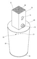
Figure 3 is a perspective view of the lamp lantern the present invention is separated
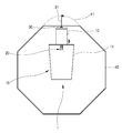
Figure 4 is an internal incision diagram of the lamp lamp separated the present invention
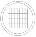
5 is a plan view of a lantern in which the present invention lamp is separated
Figure 6 is a bottom view of the lantern with the present invention lampshade separated
7 is a front view of a lantern in which the present invention lamp is separated
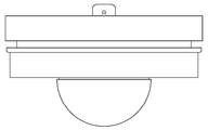
8 is a perspective view of the lampshade of the present invention coupled
9 is a front view of the lampshade of the present invention coupled
The present invention relates to a lantern, in the lantern, the
In addition, the case 150 of the lantern is composed of a
In addition, a
The present invention will be described in detail with reference to the accompanying drawings. 1 is a perspective view of a conventional lantern, Figure 2 is a conventional lantern coupling, Figure 3 is a perspective view of a lamp separated the present invention lampshade, Figure 4 is an internal cut-out diagram of the lamp lamp the present invention lamp is separated, Figure 5 is a present invention lampshade Figure 6 is a plan view of the separated lamp, Figure 6 is a lower view of the lamp is separated the present invention lampshade, Figure 7 is a front view of the lamp lamp is separated the present invention lamp, Figure 8 is a perspective view of the lampshade combined the present invention lamp, Figure 9 is The front view of the lampshade of the present invention is combined.
The solar cell of the present invention has a rated current of 2.5V and a maximum current of 120mAh, and uses crystal line silicon (58mm x 45mm).
Referring to the rechargeable battery and the light emitting unit of the present invention, the operating voltage of the rechargeable battery is 2.8V to 3.2V, and the current is 20 to 25mAh. The amount of power is 0.07 W x 2 = 0.14 W. In addition, the operating conditions are required to use after charging in direct sunlight at least 12 to 14 hours, the average operating time is about 20 hours.
The light emitting unit is provided with two high-brightness white LEDs (brightness is 12000-15000 mcd).
Case 150 of the present invention lantern is composed of a case fixing ring is formed in the center and the case body detachably coupled to the hole of the case fixing ring. The case fixing ring supports the case body inside and protects from an external shock. And the
In addition, the lower end of the
In addition, a
On the other hand, the
And the
And the mounting ring is coupled to the outer periphery of the case body, it is configured to support the lampshade at the bottom, it is screwed to the case body outer periphery to easily attach and detach the lampshade.
In the present invention, a general solar cell system that collects sunlight by solar cells and utilizes them as lighting uses conventional techniques. Soon, such a conventional technology, as described in the prior art in Korean Patent Nos. 10-257628 and 10-299947, installs a storage battery between a solar cell and a load, and charges the power generated by the solar cell in the storage battery. It was designed to supply stable power to the load even on rainy days or at night.
The voltage detection unit detects the voltage output from the solar cell and outputs a detection signal to the control unit. The control unit compares the detection signal of the voltage detection unit with a predetermined level inside the predetermined level. If the detection signal is low, the lamp lighting signal is output. That is, when the surroundings become dark, the output voltage of the solar cell is lowered. When the output voltage is lower than the predetermined level, the lamp is switched on. On the contrary, when the detection signal is higher than the predetermined level, the lamp is determined to be sunrise and the lamp is switched off. At this time, it is preferable that the control unit has a protection circuit to prevent overcharging and overdischarging for protection of an auxiliary charging unit such as a capacitor, and maintains the detected output voltage for a predetermined time in order to prevent an instantaneous malfunction of the system. At sunrise, the voltage detector of the solar cell turns off the lamp by outputting a lamp off signal because the detection signal is higher than a predetermined level. Therefore, since the lamp is turned off during the day and the solar cell voltage detector has a lower detection signal than the predetermined level, the lamp is turned on by outputting a lamp lighting signal. Since the voltage detection unit is also conventionally known, detailed description thereof will be omitted.
Therefore, the present invention can continuously supply power by using solar cells, and the lampshade can be easily disassembled and assembled, so that lampshades of various designs can be installed, and after removing the lampshade for students' teaching materials or leisure Because it can be used for the purpose, it is environmentally friendly to reduce the cause of polluting the environment and to maintain the clean nature by illegally dumping the used battery.
100: light 141: LED lamp
142
150: case 151: case fixing ring
152: case body 153: switch
154: PCB 122: battery
155: battery holder 160: mounting ring
170: solar cell 190: lampshade
Claims (3)
Priority Applications (1)
| Application Number | Priority Date | Filing Date | Title |
|---|---|---|---|
| KR1020110020113A KR20120101958A (en) | 2011-03-07 | 2011-03-07 | Multipurpose a lotus flower type led-candle by the photovoltaic power |
Applications Claiming Priority (1)
| Application Number | Priority Date | Filing Date | Title |
|---|---|---|---|
| KR1020110020113A KR20120101958A (en) | 2011-03-07 | 2011-03-07 | Multipurpose a lotus flower type led-candle by the photovoltaic power |
Publications (1)
| Publication Number | Publication Date |
|---|---|
| KR20120101958A true KR20120101958A (en) | 2012-09-17 |
Family
ID=47110731
Family Applications (1)
| Application Number | Title | Priority Date | Filing Date |
|---|---|---|---|
| KR1020110020113A KR20120101958A (en) | 2011-03-07 | 2011-03-07 | Multipurpose a lotus flower type led-candle by the photovoltaic power |
Country Status (1)
| Country | Link |
|---|---|
| KR (1) | KR20120101958A (en) |
Cited By (2)
| Publication number | Priority date | Publication date | Assignee | Title |
|---|---|---|---|---|
| KR101715065B1 (en) * | 2016-06-15 | 2017-03-10 | 김명숙 | Hanger For hanging Lotus Lantern And Lotus Lantern Including The Same |
| US20190219250A1 (en) * | 2016-09-19 | 2019-07-18 | Ikea Supply Ag | Lighting device with releasably connected shade |
-
2011
- 2011-03-07 KR KR1020110020113A patent/KR20120101958A/en not_active Application Discontinuation
Cited By (3)
| Publication number | Priority date | Publication date | Assignee | Title |
|---|---|---|---|---|
| KR101715065B1 (en) * | 2016-06-15 | 2017-03-10 | 김명숙 | Hanger For hanging Lotus Lantern And Lotus Lantern Including The Same |
| US20190219250A1 (en) * | 2016-09-19 | 2019-07-18 | Ikea Supply Ag | Lighting device with releasably connected shade |
| US11674669B2 (en) * | 2016-09-19 | 2023-06-13 | Ikea Supply Ag | Lighting device with releasably connected shade |
Similar Documents
| Publication | Publication Date | Title |
|---|---|---|
| ES2513815T3 (en) | Public streetlight with solar powered LED with automatic light control | |
| CN102032521B (en) | Light emitting diode lamp | |
| US8708515B2 (en) | Combination solar and oil torch | |
| CA2591322C (en) | Solar rechargeable light emitting diode lights | |
| KR100903803B1 (en) | Single unit obstacle lights | |
| US20180067384A1 (en) | Led project light has multiple functions | |
| KR101218372B1 (en) | Portable lanterns | |
| KR200405396Y1 (en) | All-in-one designed solar light system with LED lamp | |
| KR20120101958A (en) | Multipurpose a lotus flower type led-candle by the photovoltaic power | |
| CN100458270C (en) | Multifunctional emergency light | |
| KR20110026060A (en) | Stone lantern using sun light | |
| KR20160086588A (en) | Solar street light controlled by smart phone | |
| KR20150002797U (en) | lotus lamp | |
| CN100424409C (en) | Solar flashlight | |
| KR101206469B1 (en) | Led illumination lamp | |
| CN202647536U (en) | Focusing type rechargeable desk lamp | |
| CN105910056A (en) | Solar pole cap lamp | |
| CN201652119U (en) | Solar energy induction wall lamp | |
| CN2916359Y (en) | Electronic energy-saving lamps | |
| CN219673998U (en) | Folding solar camping lamp | |
| CN217482643U (en) | Solar energy birdcage torch lawn lamp | |
| KR20130006428U (en) | Charge your mobile devices equipped with a multi-purpose IT equipment streetlight | |
| KR200353145Y1 (en) | Lantern using solar cell | |
| CN203363946U (en) | High-brightness integrated solar navigation lamp | |
| CN210951100U (en) | Solar ground plug lamp |
Legal Events
| Date | Code | Title | Description |
|---|---|---|---|
| A201 | Request for examination | ||
| E902 | Notification of reason for refusal | ||
| E601 | Decision to refuse application |