KR20120096494A - Systems and methods for delivering power in response to a connection event - Google Patents
Systems and methods for delivering power in response to a connection event Download PDFInfo
- Publication number
- KR20120096494A KR20120096494A KR20127012901A KR20127012901A KR20120096494A KR 20120096494 A KR20120096494 A KR 20120096494A KR 20127012901 A KR20127012901 A KR 20127012901A KR 20127012901 A KR20127012901 A KR 20127012901A KR 20120096494 A KR20120096494 A KR 20120096494A
- Authority
- KR
- South Korea
- Prior art keywords
- energy source
- interface
- switching element
- coupled
- power
- Prior art date
Links
Images

Classifications
-
- H—ELECTRICITY
- H02—GENERATION; CONVERSION OR DISTRIBUTION OF ELECTRIC POWER
- H02J—CIRCUIT ARRANGEMENTS OR SYSTEMS FOR SUPPLYING OR DISTRIBUTING ELECTRIC POWER; SYSTEMS FOR STORING ELECTRIC ENERGY
- H02J7/00—Circuit arrangements for charging or depolarising batteries or for supplying loads from batteries
- H02J7/0047—Circuit arrangements for charging or depolarising batteries or for supplying loads from batteries with monitoring or indicating devices or circuits
- H02J7/0048—Detection of remaining charge capacity or state of charge [SOC]
-
- H—ELECTRICITY
- H02—GENERATION; CONVERSION OR DISTRIBUTION OF ELECTRIC POWER
- H02J—CIRCUIT ARRANGEMENTS OR SYSTEMS FOR SUPPLYING OR DISTRIBUTING ELECTRIC POWER; SYSTEMS FOR STORING ELECTRIC ENERGY
- H02J1/00—Circuit arrangements for dc mains or dc distribution networks
-
- H—ELECTRICITY
- H02—GENERATION; CONVERSION OR DISTRIBUTION OF ELECTRIC POWER
- H02J—CIRCUIT ARRANGEMENTS OR SYSTEMS FOR SUPPLYING OR DISTRIBUTING ELECTRIC POWER; SYSTEMS FOR STORING ELECTRIC ENERGY
- H02J1/00—Circuit arrangements for dc mains or dc distribution networks
- H02J1/10—Parallel operation of dc sources
- H02J1/108—Parallel operation of dc sources using diodes blocking reverse current flow
-
- H—ELECTRICITY
- H02—GENERATION; CONVERSION OR DISTRIBUTION OF ELECTRIC POWER
- H02J—CIRCUIT ARRANGEMENTS OR SYSTEMS FOR SUPPLYING OR DISTRIBUTING ELECTRIC POWER; SYSTEMS FOR STORING ELECTRIC ENERGY
- H02J2300/00—Systems for supplying or distributing electric power characterised by decentralized, dispersed, or local generation
- H02J2300/30—The power source being a fuel cell
Abstract
제1 에너지 소스(116)로부터 제2 에너지 소스(118)로 전력을 전달하기 위한 시스템들 및 방법들이 제공된다. 제1 에너지 소스(116)로부터 제2 에너지 소스(118)로 전력을 전달하기 위한 전기 시스템(100)은 상기 제2 에너지 소스에 결합되도록 구성되는 인터페이스(114), 상기 제1 에너지 소스와 상기 인터페이스 사이에 결합된 스위칭 요소(108), 및 상기 스위칭 요소 및 상기 인터페이스에 결합된 프로세싱 시스템(122)을 포함한다. 상기 프로세싱 시스템은, 상기 인터페이스가 상기 제2 에너지 소스(118)에 결합되어 있음을 표시하는 상기 인터페이스(114)의 전기 특성에 기초하여 접속 이벤트를 식별하고(404), 상기 접속 이벤트를 식별하는 것에 응답하여, 상기 제1 에너지 소스(116)로부터의 전류를 위한 경로를 제공(406)하도록 상기 스위칭 요소(108)를 동작시키도록 구성된다.Systems and methods are provided for transferring power from a first energy source 116 to a second energy source 118. An electrical system 100 for transferring power from a first energy source 116 to a second energy source 118 is configured to be coupled to the second energy source 114, the interface with the first energy source A switching element 108 coupled between, and a processing system 122 coupled to the switching element and the interface. The processing system is configured to identify a connection event based on the electrical characteristics of the interface 114 indicating that the interface is coupled to the second energy source 118 (404), and to identify the connection event. In response, the switching element 108 is configured to operate 406 to provide 406 a path for current from the first energy source 116.

Description
본원에 설명된 요지의 실시예들은 일반적으로 전기 시스템에 관한 것이고, 더욱 구체적으로, 요지의 실시예들은 전자 디바이스에 전력을 충전하거나 그렇지 않으면 전달할 때, 전기 그리드와 같은 에너지 소스로부터 전력을 효율적으로 활용하는 전기 시스템들에 관한 것이다.Embodiments of the subject matter described herein relate generally to an electrical system, and more particularly, embodiments of the subject matter efficiently utilize power from an energy source, such as an electrical grid, when charging or otherwise delivering power to an electronic device. To electrical systems.
많은 전자 디바이스는 직류(DC)로 동작한다. 그러나, 대부분의 전기 전송 및/또는 분배 시스템들은 교류(AC)를 제공한다. 따라서, 많은 전자 디바이스는 AC 서플라이(예를 들어, 본선 전기 서플라이(mains electrical supply))로부터의 AC 전력을 전자 디바이스를 동작 및/또는 충전하는 데 이용될 수 있는 DC 전력으로 변환하기 위해, AC 어댑터, 월 어댑터(wall adapter), 월 와트(wall wart), 또는 충전기라고 다양하게 지칭되는, AC-DC 파워 어댑터를 활용한다. 많은 파워 어댑터는 대기 전력을 소모하고, 즉, 그것들은 전자 디바이스가 접속해제되거나 완충되거나 턴 오프(turn off)될 수 있더라도 전력을 소모한다. 사용자들은 일상적으로 파워 어댑터들을 AC 서플라이에 플러그인(plug in)되거나 그렇지 않으면 접속된 채로 놓아둔다. 결과로서, 파워 어댑터들의 광범위한 이용은 상당한 양의 대기 전력을 소모하고, 이것은 또한 유용성이 거의 없거나 전혀 없고 전기 에너지를 실질적으로 낭비한다.Many electronic devices operate with direct current (DC). However, most electrical transmission and / or distribution systems provide alternating current (AC). Thus, many electronic devices use AC adapters to convert AC power from an AC supply (eg, mains electrical supply) to DC power that can be used to operate and / or charge the electronic device. Utilizes an AC-DC power adapter, variously referred to as a wall adapter, wall wart, or charger. Many power adapters consume standby power, i.e. they consume power even if the electronic device can be disconnected, buffered, or turned off. Users routinely leave power adapters plugged in or otherwise connected to an AC supply. As a result, widespread use of power adapters consumes a considerable amount of standby power, which also has little or no utility and substantially wastes electrical energy.
요지의 더욱 완전한 이해는 다음의 도면들과 결합하여 고려될 때 상세한 설명 및 청구항들을 참조함으로써 얻어질 수 있고, 도면들 전체에 걸쳐서 동일한 참조 번호들은 유사한 요소들을 가리킨다.
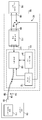
도 1은 본 발명의 일 실시예에 따른 파워 어댑터에서 이용하는 데 적합한 전기 시스템의 블록도이다.
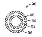
도 2는 본 발명의 일 실시예에 따른 도 1의 전기 시스템을 갖는 디바이스 인터페이스로서 이용하는 데 적합한 실드 케이블(shielded cable)의 단면도이다.
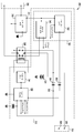
도 3은 본 발명의 일 실시예에 따른 파워 어댑터에서 이용하는 데 적합한 전기 시스템의 개략도이다.
도 4는 본 발명의 일 실시예에 따른 도 1 또는 도 3의 전기 시스템과 사용하는 데 적합한 전력 관리 프로세스의 흐름도이다.A more complete understanding of the subject matter may be obtained by referring to the detailed description and claims when considered in conjunction with the following figures, wherein like reference numerals refer to like elements throughout.
1 is a block diagram of an electrical system suitable for use in a power adapter according to one embodiment of the invention.
2 is a cross-sectional view of a shielded cable suitable for use as a device interface with the electrical system of FIG. 1 in accordance with an embodiment of the present invention.
3 is a schematic diagram of an electrical system suitable for use in a power adapter according to one embodiment of the invention.
4 is a flow chart of a power management process suitable for use with the electrical system of FIG. 1 or 3 in accordance with one embodiment of the present invention.
다음의 상세한 설명은 단지 사실상 예시이고 요지의 실시예들 또는 이러한 시스템들의 응용 및 이용들을 한정하도록 의도되지 않는다. 본원에 이용된 바와 같이, "예시적"이라는 단어는 "예시, 사례 또는 실례의 역할을 함"을 의미한다. 본원에 예시적인 것으로서 설명된 임의의 구현은 반드시 다른 구현들보다 바람직하거나 유익한 것으로서 해석되지는 않는다. 또한, 앞선 기술 분야, 배경, 또는 다음의 상세한 설명에 제공된 임의의 표현된 또는 암시된 이론에 의해 속박되는 것으로 의도되지 않는다.The following detailed description is merely exemplary in nature and is not intended to limit the embodiments of the subject matter or the applications and uses of such systems. As used herein, the word "exemplary" means "acting as an example, example or example." Any implementation described as illustrative herein is not necessarily to be construed as preferred or advantageous over other implementations. Moreover, it is not intended to be bound by any expressed or implied theory provided in the foregoing technical field, background, or the following detailed description.
다음의 설명은 함께 "접속" 또는 "결합"되는 요소들 또는 노드들 또는 특징들을 참조한다. 본원에서 이용된 바와 같이, 달리 명백하게 언급하지 않는 한, "접속된"은 한 요소가 직접적으로 다른 요소에 조인됨(또는 직접적으로 그와 통신함)을 의미하고, 반드시 기계적으로는 아니다. 마찬가지로, 달리 명백히 언급하지 않는 한, "결합된"은 한 요소가 다른 요소에 직접적으로 또는 간접적으로 조인됨(또는 직접적으로 또는 간접적으로 그와 통신함)을 의미하고, 반드시 기계적으로는 아니다. 따라서, 도면들에 도시된 도식은 요소들의 하나의 예시적인 배열을 도시하지만, 부가적인 중간 요소들, 디바이스들, 특징들, 또는 컴포넌트들이 도시된 요지의 실시예에 제공될 수 있다.The following description refers to elements or nodes or features that are "connected" or "coupled" together. As used herein, unless explicitly stated otherwise, “connected” means that one element is directly joined to (or in direct communication with) another element, and not necessarily mechanically. Likewise, unless explicitly stated otherwise, “coupled” means that one element is directly or indirectly joined to (or in communication with, directly or indirectly to) another element, but not necessarily mechanically. Thus, while the diagram shown in the figures shows one exemplary arrangement of elements, additional intermediate elements, devices, features, or components may be provided in the embodiment of the subject matter shown.
간결성을 위해, 전력 변환, 배터리 충전 시스템들 및/또는 스킴들, 캐패시턴스 감지, 전압 감지, 시그널링, 및 시스템들의 다른 기능 양태들(및 시스템들의 개별 동작 컴포넌트들)과 관련된 종래의 기법들은 본원에서 상세히 설명되지 않을 수 있다. 또한, 본원에 포함된 다양한 도면들에 도시된 접속하는 선들은 다양한 요소들 사이에 예시적인 기능 관계들 및/또는 물리적 결합들을 표현하도록 의도된다. 많은 대안적인 또는 부가적인 기능 관계들 또는 물리적 접속들이 요지의 실시예에 제공될 수 있다는 것에 주목해야 한다. 또한, 특정 전문 용어들이 또한 참조의 목적으로만 다음의 설명에 이용될 수 있고, 따라서 한정하는 것으로 의도되지 않으며, 구조들을 가리키는 "제1", "제2" 및 다른 이러한 수치 용어들은 문맥에 의해 명백하게 표시되지 않는 한 시퀀스 또는 순서를 암시하지 않는다.For brevity, conventional techniques related to power conversion, battery charging systems and / or schemes, capacitance sensing, voltage sensing, signaling, and other functional aspects of the systems (and individual operating components of the systems) are described in detail herein. It may not be explained. In addition, the connecting lines shown in the various figures included herein are intended to represent exemplary functional relationships and / or physical couplings between the various elements. It should be noted that many alternative or additional functional relationships or physical connections may be provided in the embodiments of the subject matter. In addition, certain terminology may also be used in the following description for reference purposes only, and therefore are not intended to be limiting, and the terms “first”, “second” and other such numerical terms indicating structures are intended to be in the context of context. It does not imply a sequence or order unless explicitly indicated.
본원에 논의된 기술들 및 개념들은 전자 디바이스 및/또는 타겟 에너지 소스에 전기 전력을 효율적으로 전달하기 위한 시스템들 및/또는 방법들에 관한 것이다. 래칭 릴레이(latching relay)와 같은 스위칭 요소를 활용하여 전자 디바이스 및/또는 타겟 에너지 소스에 결합되는 인터페이스에 응답하여 자동으로 공급 에너지 소스로부터의 전류를 위한 경로를 구축한다. 예시적인 실시예에서, 인터페이스는 실드 케이블로서 실현되고, 스위칭 요소는 실드 케이블이 전자 디바이스 및/또는 타겟 에너지 소스에 플러그 인(plug in)되어 있음을 표시하는 실드의 상태 또는 특성을 검출하거나 그렇지 않으면 식별하는 것에 응답하여 공급 에너지 소스로부터의 전기 전류를 위한 경로를 제공하도록 동작된다. 스위칭 요소는 전력이 더 이상 전자 디바이스 및/또는 타겟 에너지 소스에 의해 요구되지 않을 때, 예를 들어, 타겟 에너지 소스가 완충(또는 충전 상태 임계값 위로 충전)되거나 또는 인터페이스가 전자 디바이스 및/또는 타겟 에너지 소스로부터 분리될 때 공급 에너지 소스로부터의 전류를 막도록 동작된다. 결과로서, 인터페이스가 전자 디바이스 및/또는 타겟 에너지 소스에 결합되지 않을 때 또는 전자 디바이스 및/또는 타겟 에너지 소스가 공급 에너지 소스로부터의 전력을 요구하지 않을 때 공급 에너지 소스로부터의 전력이 낭비되지 않는다.The techniques and concepts discussed herein relate to systems and / or methods for efficiently delivering electrical power to electronic devices and / or target energy sources. A switching element, such as a latching relay, is utilized to automatically establish a path for current from the supply energy source in response to an interface coupled to the electronic device and / or the target energy source. In an exemplary embodiment, the interface is realized as a shielded cable, and the switching element detects or otherwise detects the state or characteristic of the shield indicating that the shielded cable is plugged in to the electronic device and / or the target energy source. In response to identifying, it is operated to provide a path for electrical current from the supply energy source. The switching element may, for example, when power is no longer required by the electronic device and / or target energy source, for example, the target energy source is buffered (or charged above the charge state threshold) or the interface is electronic device and / or target. It is operated to block current from the supply energy source when disconnected from the energy source. As a result, power from the supply energy source is not wasted when the interface is not coupled to the electronic device and / or target energy source or when the electronic device and / or target energy source does not require power from the supply energy source.
도 1은 모바일 디바이스(예를 들어, 셀룰러 전화기, 퍼스널 디지털 어시스턴트 등), 컴퓨터(예를 들어, 랩톱 컴퓨터, 퍼스널 컴퓨터, 넷북 컴퓨터 등), 디지털 오디오 플레이어, 전자책 판독기, 또는 다른 적절한 전자 디바이스와 같은, 전자 디바이스(104)를 위한 파워 어댑터(102)와 이용하는 데 적합한 전기 시스템(100)의 예시적인 실시예를 도시한다. 예시적인 실시예에서, 전기 시스템(100)은 제1 인터페이스(106), 스위칭 요소(108), 전력 변환 모듈(110), 전력 관리 시스템(112) 및 제2 인터페이스(114)를 포함하고, 이것으로 한정하지 않는다. 도 1은 표현의 목적을 위해 그리고 설명의 용이성을 위해 전기 시스템(100)의 표현을 간략화한 것이고 본원에 설명된 요지를 임의의 방식으로 한정하도록 의도되지 않는다는 것을 이해해야 한다. 전기 시스템(100)의 실제적인 실시예들은 본원에 설명되지 않은 부가적인 기능을 수행하도록 구성되는 부가적인 컴포넌트들 및/또는 요소들을 포함할 수 있다는 것을 알 것이다.1 illustrates a mobile device (eg, cellular telephone, personal digital assistant, etc.), computer (eg, laptop computer, personal computer, netbook computer, etc.), digital audio player, e-book reader, or other suitable electronic device. Likewise, an exemplary embodiment of an
예시적인 실시예에서, 스위칭 요소(108)는 스위칭 요소(108)가 제1 인터페이스(106)에 결합된 공급 에너지 소스(116)로부터 전력 변환 모듈(110)로의 전류(또는 전력) 흐름을 막거나 허용하도록, 제1 인터페이스(106)와 전력 변환 모듈(110) 사이에 전기적으로 직렬로 구성된다. 아래에서 더 상세히 설명되는 바와 같이, 예시적인 실시예에서, 전력 관리 시스템(112)은 공급 에너지 소스(116) 및/또는 제1 인터페이스(106)로부터의 전류를 위한 경로를 제공하기 위해 전자 디바이스(104)에 결합되는 제2 인터페이스(114)에 응답하여 스위칭 요소(108)를 자동으로 동작(예를 들어, 폐쇄 또는 턴 온)하도록 구성되어, 공급 에너지 소스(116)로부터의 전력이 제2 인터페이스(114)를 통해 전자 디바이스(104) 및/또는 타겟 에너지 소스(118)에 전달될 수 있게 한다. 편의상, 그러나 한정하지 않고, 제1 인터페이스(106)는 대안적으로 본원에서 공급 인터페이스라고 할 수 있고, 제2 인터페이스(114)는 대안적으로 본원에서 디바이스 인터페이스라고 할 수 있다.In an exemplary embodiment, the
하나 이상의 실시예에 따르면, 공급 에너지 소스(116)는 대부분의 빌딩들, 주택들, 또는 전기 전력 그리드(예를 들어, 본선 전기 또는 그리드 전력) 내의 다른 구조들에 공통인 단상 AC 파워 서플라이와 같은 교류(AC) 파워 서플라이로서 실현된다. 따라서, 편의상, 그러나 한정하지 않고, 공급 에너지 소스(116)는 대안적으로 본원에서 AC 에너지 소스라고 할 수 있고, 제1 인터페이스(106)는 대안적으로 본원에서 AC 인터페이스라고 할 수 있다. 그러나, 요지는 본원에서 AC 파워 서플라이의 문맥에서 설명될 수 있지만, 다른 실시예들에서, 공급 에너지 소스(116)는 예를 들어, 태양 전지, 연료 전지, 배터리, 또는 다른 적절한 DC 파워 서플라이와 같은 직류(DC) 파워 서플라이로서 실현될 수 있다는 것을 알아야 한다. AC 에너지 소스(116)의 전압 및/또는 주파수는 전기 시스템(100) 및/또는 파워 어댑터(102)가 활용되고 있는 지리적 영역에 따라 달라질 수 있다는 것을 알 것이다. 예를 들어, 미국에서, AC 에너지 소스(116)는 60 Hz에서 120 볼트(Volt) 또는 240 볼트로서 실현될 수 있고, 다른 지역들에서 AC 에너지 소스(116)는 50 Hz에서 110 볼트 또는 220 볼트로서 실현될 수 있다.According to one or more embodiments, the
예시적인 실시예에서, AC 인터페이스(106)는, 전기 시스템(100)과 AC 에너지 소스(116) 사이에 전기 인터페이스를 제공하기 위해서 AC 에너지 소스(116)의 대응하는 물리적 특징(예를 들어, 월 소켓 또는 콘센트)과 인터페이스, 메이트(mate), 또는 그렇지 않으면 전기 접속을 구축하도록 적응되는 플러그 또는 다른 적절한 물리적 특징을 포함한다. 하나 이상의 실시예에 따르면, 파워 어댑터(102)는 플러그 인 또는 벽 부착형 파워 어댑터(또는 월 와트)로서 실현되고, 스위칭 요소(108), 전력 변환 모듈(110) 및 전력 관리 시스템(112)은 AC 인터페이스(106)와 가까이 배치되거나 및/또는 통합된다. 대안적인 실시예들에서, 이 기술분야에서 알 수 있는 바와 같이, 파워 어댑터(102)는 도킹 스테이션 또는 도킹 플랫폼과 실현될 수 있고, 스위칭 요소(108), 전력 변환 모듈(110) 및 전력 관리 시스템(112)은 디바이스 인터페이스(114)와 통합되고 AC 인터페이스(106)로부터 멀리 배치된다.In an exemplary embodiment, the
예시적인 실시예에서, 아래에서 더 상세히 설명되는 바와 같이, 스위칭 요소(108)가 AC 에너지 소스(116)로부터 전력 변환 모듈(110)의 입력(109)으로의 전기 전류(또는 전력)의 흐름을 조절 또는 그렇지 않으면 제어하는 데 활용될 수 있도록, 스위칭 요소(108)는 전력 변환 모듈(110)의 입력(109)과 AC 인터페이스(106) 사이에 결합되고 전력 변환 모듈(110)과 AC 인터페이스(106) 사이에 직렬로 전기적으로 구성된다. 예시적인 실시예에서, 전력 변환 모듈(110)의 출력(111)은 전력 관리 시스템(112)을 통해 디바이스 인터페이스(114)에 결합된다. 아래에서 더 상세히 설명되는 바와 같이, 전력 관리 시스템(112)은 전력 변환 모듈(110)의 출력(111)으로부터 전자 디바이스(104) 및/또는 타겟 에너지 소스(118)로의 전력의 전달 및/또는 흐름을 조절한다.In an exemplary embodiment, as described in more detail below, the
예시적인 실시예에서, 스위칭 요소(108)는 전력 관리 시스템(112)으로부터의 전기 신호에 응답하여 그의 상태를 변화하도록 구성되는 래칭 릴레이로서 실현된다. 대안적인 실시예들에서, 스위칭 요소(108)는 비-래칭 릴레이, 고체 상태 스위치, 콘택터(contactor), 또는 다른 적절한 스위칭 장치로서 실현될 수 있다. 예시적인 실시예에서, 제1 상태(예를 들어, 폐쇄 상태 또는 온 상태)에서, 스위칭 요소(108)는 AC 인터페이스(106) 및/또는 AC 에너지 소스(116)로부터 전력 변환 모듈(110)에 전류(또는 전력 흐름)를 위한 경로를 제공하거나 그렇지 않으면 구축한다. 제2 상태(예를 들어, 개방 상태 또는 오프 상태)에서, 스위칭 요소(108)는 AC 인터페이스(106) 및/또는 AC 에너지 소스(116)로부터 전력 변환 모듈(110)로의 전류의 흐름을 막거나 그렇지 않으면 금지한다. 이와 관련하여, 전기 시스템(100) 및/또는 파워 어댑터(102)는 스위칭 요소(108)가 오픈 상태에 있을 때 AC 에너지 소스(116)로부터 실질적으로 제로 전류 또는 전력을 소모한다. 아래에서 더 상세히 설명되는 바와 같이, 예시적인 실시예에서, 스위칭 요소(108)는, 파워 어댑터(102)가 디바이스 인터페이스(114)에 결합된 타겟 에너지 소스(118) 및/또는 전자 디바이스(104)에 의해 희망되거나 및/또는 요구될 때 AC 에너지 소스(116)로부터의 전류(또는 전력)를 소모하고 다른 때에는 전류(또는 전력)를 소모하지 않도록 동작된다. 따라서, 파워 어댑터(102)는 "제로 드로(zero draw)" 디바이스이거나, 다시 말해, 파워 어댑터(102)는 실질적으로 제로 대기 전력을 소모한다.In an exemplary embodiment, the switching
예시적인 실시예에서, 전력 변환 모듈(110)은 그의 입력(109)에서 AC 에너지 소스(116)로부터의 전압 및/또는 전류를 타겟 에너지 소스(118)를 위해 적절한 그의 출력(111)에서 전압 레벨 및/또는 전류 레벨로 변환하도록 구성된다. 예시적인 실시예에서, 타겟 에너지 소스(118)는 직류(DC) 에너지 저장 요소로서 실현되고, 전력 변환 모듈(110)은 AC 에너지 소스(116)로부터의 AC 전력을 타겟 에너지 소스(118)에 적절한 DC 전압 레벨로 변환한다. 예시적인 실시예에서, 타겟 에너지 소스(118)는 리튬 이온 배터리, 니켈 수소 배터리, 니켈 카드뮴 배터리, 연산 배터리 등과 같은 재충전가능한 배터리(또는 재충전가능한 배터리 팩)로서 실현된다. 대안적인 실시예들에서, 타겟 에너지 소스(118)는 캐패시터(예를 들어, 울트라캐패시터 또는 수퍼 캐패시터) 또는 다른 적절한 에너지 저장 요소로서 실현될 수 있다. 예시적인 실시예에서, 전력 변환 모듈(110)은 입력(109)에 결합된 변압기(또는 변압기 스테이지) 다음에 변압기와 출력(111) 사이의 정류기(또는 정류 스테이지)를 포함하고, 입력(109)에서 AC 전력(또는 전류)에 응답하여, 변압기 및 정류기는 협력하여 타겟 에너지 소스(118)에 적절한 전력 변환 모듈(110)의 출력(111)에서 DC 전압 레벨을 생성하도록 구성된다. 예를 들어, 예시적인 실시예에서, 전력 변환 모듈(110)은 타겟 에너지 소스(118)가 완충될 때 (예를 들어, 실제적 및/또는 현실적 동작 허용 오차들 내에서) 타겟 에너지 소스(118)의 공칭 전압과 실질적으로 동일한 출력(111)에서의 DC 전압을 생성한다. 대안적인 실시예들에서, 이 기술분야에서 알 수 있는 바와 같이, 공급 에너지 소스(116)가 DC 에너지 소스로서 실현되는 경우, 전력 변환 모듈(110)은 적절하게 구성된 DC-DC 변환기로서 실현된다는 것에 주목해야 한다.In an exemplary embodiment, the
전력 관리 시스템(112)은 일반적으로 전력 변환 모듈(110)의 출력(111) 및/또는 AC 에너지 소스(116)로부터 타겟 에너지 소스(118)로의 전력의 전달 및/또는 흐름을 조절하도록 구성되는 하드웨어, 펌웨어, 프로세싱 로직 및/또는 소프트웨어의 결합을 표현한다. 예시적인 실시예에서, 전력 관리 시스템(112)은 전력 회로(120), 프로세싱 시스템(122), 및 내부 에너지 소스(124)를 포함한다. 전력 회로(120)는 전력 변환 모듈(110)의 출력(111)과 디바이스 인터페이스(114) 사이에 결합된다. 예시적인 실시예에서, 전력 회로(120)는 프로세싱 시스템(122)이 전력 변환 모듈(110)의 출력(111)으로부터 전자 디바이스(104) 및/또는 타겟 에너지 소스(118)로의 전력 흐름을 조절, 감시, 또는 그렇지 않으면 제어할 수 있게 하도록 적절하게 구성되는 H 브리지 및/또는 다른 회로를 포함한다. 전력 회로(120)는 또한 내부 에너지 소스(124)에 결합되고, 내부 에너지 소스(124)로/로부터의 양방향 전류 흐름(또는 전력 흐름)을 허용하거나 그렇지 않으면 프로세싱 시스템(122)이 전력 변환 모듈(110)의 출력으로부터의 전력 흐름을 제어할 수 있게 하도록 구성되는 회로를 포함한다. 일부 대안적인 실시예들에서, 전력 변환 모듈(110)의 출력(111)은 접속 장치(126)에 직접적으로 결합될 수 있다는 것에 주목해야 한다.The
예시적인 실시예에서, 프로세싱 시스템(122)은 전력 회로(120), 내부 에너지 소스(124), 및 디바이스 인터페이스(114)에 결합된다. 프로세싱 시스템(122)은 일반적으로 스위칭 요소(108), 전력 회로(120)를 동작시키고 아래에서 더 상세히 설명된 부가적인 태스크들, 기능들, 및/또는 동작들을 수행하도록 구성되는 하드웨어, 펌웨어, 프로세싱 로직 및/또는 소프트웨어를 표현한다. 예시적인 실시예에서, 내부 에너지 소스(124)는 스위칭 요소(108)가 개방 상태에 있을 때 전력 관리 시스템(112)에 전력을 제공하도록 구성되는 재충전가능한 에너지 저장 요소로서 실현된다. 예시적인 실시예에서, 내부 에너지 소스(124)는 소형 인자(small form-factor)를 갖는 재충전가능한 배터리(예를 들어, 리튬 이온 코인 셀 배터리)로서 실현되지만, 대안적인 실시예들에서, 내부 에너지 소스(124)는 캐패시터(예를 들어, 울트라캐패시터 또는 수퍼 캐패시터), 태양 전지, 또는 다른 적절한 에너지 소스로서 실현될 수 있다.In an exemplary embodiment, the
예시적인 실시예에서, 프로세싱 시스템(122)은 본원에 설명된 태스크들, 기능들, 및/또는 동작들을 수행하도록 구성되는 하나 이상의 마이크로컨트롤러로서 실현된다. 대안적인 실시예들에서, 프로세싱 시스템(122)은 본원에 설명된 기능들을 지원 및/또는 수행하도록 설계되는, 범용 프로세서, 컨트롤러, 마이크로프로세서, 상태 머신, 내용 주소화 메모리(content addressable memory), 디지털 신호 프로세서, ASIC(application specific integrated circuit), FPGA(field programmable gate array), 임의의 적절한 프로그램 가능한 로직 디바이스, 개별(discrete) 게이트 또는 트랜지스터 로직, 개별 하드웨어 컴포넌트들, 또는 그의 임의의 결합과 실현될 수 있다. 프로세싱 시스템(122)은 또한 컴퓨팅 디바이스들, 예를 들어, 복수의 프로세싱 코어들의 결합, 또는 임의의 다른 그러한 구성으로서 구현될 수 있다. 실제로, 프로세싱 시스템(122)은 아래에 더 상세히 설명되는 바와 같이, 전기 시스템(100)의 동작과 연관된 기능들, 기법들, 및 프로세싱 태스크들을 실행하도록 구성되는 프로세싱 로직을 포함한다. 또한, 본원에 개시된 실시예들과 결합하여 설명된 방법 또는 알고리즘의 단계들은 하드웨어에, 펌웨어에, 프로세싱 시스템(122)에 의해 실행되는 소프트웨어 모듈에, 또는 그의 임의의 실제 결합에 직접적으로 구체화될 수 있다. 예시적인 실시예에서, 프로세싱 시스템(122) 및 전력 회로(120)는 단일 집적 회로 패키지(또는 칩) 내에 캡슐화(encapsulated) 또는 그렇지 않으면 포함될 수 있지만, 대안적인 실시예들에서, 프로세싱 시스템(122) 및 전력 회로(120)는 복수의 집적 회로 패키지들(또는 칩들), 복수의 개별 컴포넌트들, 또는 그의 결합으로서 구현될 수 있다.In an example embodiment, the
예시적인 실시예에서, 디바이스 인터페이스(114)는 전자 디바이스(104) 및/또는 타겟 에너지 소스(118)에 결합되도록 구성되고 접속 장치(126) 및 감지 장치(128)를 포함한다. 접속 장치(126)는 전력 회로(120)에 결합되고, 전자 디바이스(104) 및/또는 타겟 에너지 소스(118)의 대응하는 리셉터클과 인터페이스, 메이트, 또는 그렇지 않으면 전기 접속을 구축하도록 적응되는 플러그(130)(또는 다른 적절한 물리적 특징)를 포함한다. 이와 관련하여, 플러그(130)가 전자 디바이스(104)에 삽입될 때, 전력 변환 모듈(110)의 출력(111)으로부터 전자 디바이스(104) 및/또는 타겟 에너지 소스(118)로의 전류를 위한 경로가 접속 장치(126) 및 전력 회로(120)를 통해 생성된다.In an exemplary embodiment, the
예시적인 실시예에서, 감지 장치(128)는 접속 장치(126)와 일체로 된다(integral with). 아래에서 더 상세히 설명되는 바와 같이, 프로세싱 시스템(122)은 접속 장치(126)가 전자 디바이스(104) 및/또는 타겟 에너지 소스(118)에 결합되어 있음을 표시하는 감지 장치(128)의 전기 특성 또는 상태에 기초하여 접속 이벤트를 검출 또는 그렇지 않으면 식별하고, 접속 이벤트에 응답하여 공급 에너지 소스(116)로부터의 전류를 위한 경로를 제공하도록 스위칭 요소(108)를 동작시키도록 구성된다. 부가적으로, 프로세싱 시스템(122)은 전자 디바이스(104) 및/또는 타겟 에너지 소스(118)가 더 이상 공급 에너지 소스(116)로부터의 전류를 희망 및/또는 요구하지 않음을 표시하는 접속 장치(126) 및/또는 감지 장치(128)의 상태 또는 특성에 기초하여 접속해제 이벤트를 검출 또는 그렇지 않으면 식별하고, 접속해제 이벤트에 응답하여 공급 에너지 소스(116)로부터의 전류의 흐름을 막도록 스위칭 요소(108)를 동작시키도록 구성된다.In an exemplary embodiment, the
이제 도 2를 참조하면, 예를 들어, USB(universal serial bus) 케이블, RS-232 시리얼 케이블, D-서브미니어처(또는 D-서브) 케이블, PS/2 케이블, HDMI 케이블, 또는 도 1의 전기 시스템(100)에서 디바이스 인터페이스(114)로서 이용하는 데 적절한 다른 동축 케이블과 같은 실드 케이블(200)의 예시적인 실시예가 도시된다. 예시적인 실시예에서, 실드 케이블(200)은 내부 전도성 코어(202), 내부 절연체(204), 외부 전도체(206), 및 외부 절연체(208)를 포함한다. 도시된 바와 같이, 예시적인 실시예에서, 내부 절연체(204)는 내부 전도성 코어(202)와 동축이고 내부 전도성 코어를 둘러싸고(circumscribe), 외부 전도체(206)는 내부 절연체(204)와 동축이고 외부 전도체를 둘러싸고, 외부 절연체(208)는 외부 전도체(206)와 동축이고 외부 절연체를 둘러싼다. 내부 전도성 코어(202)는 실드 케이블(200)의 일단으로부터(예를 들어, 전력 회로(120)의 출력으로부터) 실드 케이블(200)의 타단으로(예를 들어, 전자 디바이스(104) 및/또는 타겟 에너지 소스(118)로) 전기 신호를 전송하기 위한 하나 이상의 전도체들(예를 들어, 와이어들)을 포함한다. 내부 절연체(204)는 내부 전도성 코어(202)로/로부터 방사상으로 전기 신호들의 전도를 막고 절연을 제공하는, 플라스틱, 고무, 패브릭 스레드(fabric thread) 등과 같은 유전체 물질을 포함한다. 외부 전도체(206)는 내부 전도성 코어(202)의 하나 이상의 와이어들에서 전파하는 신호들에 대한 방사상의 전자기 간섭의 영향을 완화하고 전자기 차폐를 제공하는 전도성 물질을 포함한다. 따라서, 이 기술분야에서 알 수 있는 바와 같이, 외부 전도체(206)는 대안적으로 실드(shield)라고 한다. 예시적인 실시예에서, 실드(206)는 브레이디드 구리(braided copper)(또는 다른 적절한 전도체) 또는 동섬유로서 실현된다. 외부 절연체(208)는 실드(206)로/로부터 방사상으로 전기 신호들의 전도를 막고 절연을 제공하는 플라스틱, 고무, PVC(polyvinyl chloride) 등과 같은 유전체 물질을 포함한다.Referring now to FIG. 2, for example, a universal serial bus (USB) cable, an RS-232 serial cable, a D-subminiature (or D-sub) cable, a PS / 2 cable, an HDMI cable, or the electrical of FIG. 1. Exemplary embodiments of shielded
하나 이상의 실시예들에 따라, 도 2를 계속해서 참조하면서, 다시 도 1을 참조하면, 파워 어댑터(102)가 플러그 인 또는 벽 부착형 파워 어댑터로서 실현될 때, 디바이스 인터페이스(114)는 실드 케이블(200)로서 실현되고, 접속 장치(126)는 실드 케이블(200)의 내부 전도성 코어(202)를 포함하고, 감지 장치(128)는 실드 케이블(200)의 실드(206)를 포함한다. 아래에서 더 상세히 설명되는 바와 같이, 일 실시예에 따르면, 디바이스 인터페이스(114)의 플러그(130)는 플러그(130)가 전자 디바이스(104)에 접속될 때 감지 장치(128) 및/또는 실드(206)를 전기 그라운드에 접속하도록 구성되고, 프로세싱 시스템(122)은 감지 장치(128) 및/또는 실드(206)의 전압을 감시하고 감지 장치(128) 및/또는 실드(206)의 전압에 기초하여 접속 이벤트를 검출하도록 구성된다. 다른 실시예에서, 프로세싱 시스템(122)은 캐패시턴스 감지 전극으로서 감지 장치(128) 및/또는 실드(206)를 활용하고 감지 장치(128) 및/또는 실드(206)의 캐패시턴스에 기초하여 접속 이벤트를 검출하도록 구성된다.With continued reference to FIG. 2, in accordance with one or more embodiments, referring back to FIG. 1, when the
도 3은 다른 실시예에 따라 전자 디바이스를 위해 파워 어댑터와 이용하는 데 적합한 예시적인 전기 시스템(300)을 도시한다. 전기 시스템(300)은 공급 인터페이스(306), 스위칭 요소(308), 전력 변환 모듈(310), 전력 관리 시스템(312) 및 디바이스 인터페이스(314)를 포함하고, 이것으로 한정하지 않는다. 전력 관리 시스템(312)은 전력 회로(320), 프로세싱 시스템(322), 및 내부 에너지 소스(324)를 포함한다. 도 3의 다양한 요소들은 도 1의 문맥에서 전술한 상대 요소들과 유사하고, 이러한 요소들은 도 3의 문맥에서 여기서 장황하게 설명되지 않을 것이다. 예시적인 실시예에서, 디바이스 인터페이스(314)의 제1 노드(326)가 접속 장치(예를 들어, 접속 장치(126))에 접속되거나 및/또는 그와 일체로 되고, 디바이스 인터페이스(314)의 제2 노드(328)가 감지 장치(예를 들어, 감지 장치(128))에 접속되거나 및/또는 그와 일체로 된다. 도 3은 표현의 목적을 위해 그리고 설명의 용이성을 위해 전기 시스템(300)의 표현을 간략화한 것이고 본원에 설명된 요지를 임의의 방식으로 한정하도록 의도되지 않는다는 것을 이해해야 한다. 전기 시스템(300)의 실제적인 실시예들은 본원에 설명되지 않은 부가적인 기능을 수행하도록 구성되는 부가적인 컴포넌트들 및/또는 요소들을 포함할 수 있다는 것을 알 것이다.3 illustrates an example
예시적인 실시예에서, 전력 회로(320)는 배터리 관리 회로(340) 및 부하 감시 회로(342)를 포함한다. 배터리 관리 회로(340)는 일반적으로 내부 에너지 소스(324)의 전압 및/또는 충전 상태를 감시하고 전력 변환 모듈(310)의 출력(311)으로부터 내부 에너지 소스(324)를 충전하도록 구성되는 하드웨어, 펌웨어, 프로세싱 로직 및/또는 소프트웨어(또는 그의 결합)를 표현한다. 배터리 관리 회로(340)는 스위칭 요소(308)를 통해 전력 변환 모듈(310)의 출력(311) 및 내부 에너지 소스(324)에 결합된다. 예시적인 실시예에서, 아래에서 더 상세히 설명되는 바와 같이, 배터리 관리 회로(340)는 프로세싱 시스템(322)에 결합되고, 내부 에너지 소스(324)의 전압 및/또는 충전 상태에 관한 정보를 프로세싱 시스템(322)에 제공한다. 부하 감시 회로(342)는 일반적으로 디바이스 인터페이스(314)로/로부터 제공되는 전류 및/또는 전압을 감시하도록 구성되는 하드웨어, 펌웨어, 프로세싱 로직 및/또는 소프트웨어(또는 그의 결합)를 표현한다. 예시적인 실시예에서, 아래에서 더 상세히 설명되는 바와 같이, 부하 감시 회로(342)는 프로세싱 시스템(322)에 결합되고, 디바이스 인터페이스(314)로 흐르는 전류의 양에 관한 정보를 프로세싱 시스템(322)에 제공한다. 예시적인 실시예에서, 전력 관리 시스템(312)은 프로세싱 시스템(322)과 스위칭 요소(308) 사이에 결합되는 드라이버 회로(344)를 포함한다. 드라이버 회로(344)는 일반적으로 프로세싱 시스템(322)으로부터의 신호에 응답하여 스위칭 요소(308)의 상태를 변화하도록 구성되는 하드웨어를 표현한다.In an exemplary embodiment, the
도 3에 도시된 바와 같이, 예시적인 실시예에서, 스위칭 요소(308)는 DPDT(double pole double throw) 래칭 릴레이로서 실현된다. 이와 관련하여, DPDT 래칭 릴레이(308)에 대한 제1 상태(예를 들어, 폐쇄 상태 또는 온 상태)에서, DPDT 래칭 릴레이(308)는 공급 인터페이스(306)로부터 전력 변환 모듈(310)로의 전류를 위한 경로를 제공하고, DPDT 래칭 릴레이(308)는 또한 배터리 관리 회로(340)로부터 내부 에너지 소스(324)로의 전류를 위한 경로를 제공한다. DPDT 래칭 릴레이(308)가 제1 상태에 있는 동안, 전력 변환 모듈(310)은 공급 인터페이스(306)로부터의 전력을 도 1의 문맥에서 전술한 바와 유사한 방식으로 그의 출력(311)에서의 전압 레벨로 변환하고, 배터리 관리 회로(340)는 전력 변환 모듈(310)의 출력(311)으로부터 필요로 되는 바와 같이 내부 에너지 소스(324)를 감시 및/또는 충전한다. 아래에서 더 상세히 설명되는 바와 같이, 접속해제 이벤트에 응답하여, 프로세싱 시스템(322)은 드라이버 회로(344)가 DPDT 래칭 릴레이(308)의 상태를 변화(예를 들어, 개방 또는 턴 오프)하도록 하는 신호를 발생 또는 그렇지 않으면 제공한다. DPDT 래칭 릴레이(308)에 대한 제2 상태(예를 들어, 개방 상태 또는 오프 상태)에서, DPDT 래칭 릴레이(308)는 공급 인터페이스(306)로부터 전력 변환 모듈(310)로의 전류를 위한 경로를 제거함으로써 공급 인터페이스(306)로부터의 전류 흐름을 막는다. DPDT 래칭 릴레이(308)는 제2 상태에 있는 동안, 내부 에너지 소스(324)가 DPDT 래칭 릴레이(308)를 통해 노드(350)에서 프로세싱 시스템(322)에 결합되도록 구성된다. 따라서, 개방 상태(또는 오프 상태)에서, 내부 에너지 소스(324)는 프로세싱 시스템(322)에 동작 전력을 제공한다. 예시된 실시예에서, 제1 다이오드(352)는 노드(326)와 노드(350) 사이에 제공되고, 노드(350)로부터 노드(326)로 전류가 흐르지 못하도록 구성되고, 제2 다이오드(354)는 노드(350)로부터 내부 에너지 소스(324)로 전류가 흐르지 못하도록 하기 위해 DPDT 래칭 릴레이(308)와 노드(350) 사이에 제공된다. 이와 관련하여, 예시적인 실시예에서, DPDT 래칭 릴레이(308)가 제2 상태에 있을 때 내부 에너지 소스(324)가 오직 프로세싱 시스템(322)에 전력을 제공하도록 보장하기 위해서 내부 에너지 소스(324)의 전압(다이오드(354)의 온 전압보다 작음)은 바람직하게는 노드(326)에서의 전압(다이오드(352)의 온 전압보다 작음)보다 작다. 아래에서 더 상세히 설명되는 바와 같이, DPDT 래칭 릴레이(308)가 개방 상태에 있을 때, 노드(326)가 디바이스 및/또는 타겟 에너지 소스에 전기적으로 접속되어 있음을 표시하는 노드(328)에서의 신호에 응답하여, 프로세싱 시스템(322)은 드라이버 회로(344)가 DPDT 래칭 릴레이(308)의 상태를 제2 상태(또는 개방 상태)로부터 제1 상태(또는 폐쇄 상태)로 변화하도록 하는 신호를 발생 또는 그렇지 않으면 제공한다.As shown in FIG. 3, in an exemplary embodiment, the switching
이제 도 4를 참조하면, 예시적인 실시예에서, 전기 시스템은 아래에 설명되는 바와 같이 전력 관리 프로세스(400) 및 부가적인 태스크들, 기능들, 및/또는 동작들을 수행하도록 구성될 수 있다. 다양한 태스크들은 소프트웨어, 하드웨어, 펌웨어, 또는 그의 임의의 결합에 의해 수행될 수 있다. 예시적인 목적을 위해, 다음의 설명은 도 1-3과 결합하여 위에서 언급한 요소들을 참조할 수 있다. 실제로, 태스크들, 기능들, 및 동작들은 스위칭 요소(108), 전력 변환 모듈(110, 310), 전력 관리 시스템(112, 312), 전력 회로(120, 320), 프로세싱 시스템(122, 322), 접속 장치(126) 및/또는 감지 장치(128)와 같은, 설명된 시스템의 상이한 요소들에 의해 수행될 수 있다. 임의의 수의 부가적인 또는 대안적인 태스크들이 포함될 수 있고, 본원에 상세히 설명되지 않은 부가적인 기능을 갖는 더욱 종합적인 프로시저 또는 프로세스 내로 통합될 수 있다는 것을 알아야 한다.Referring now to FIG. 4, in an example embodiment, the electrical system may be configured to perform the
도 1-3을 계속해서 참조하면서, 이제 도 4를 참조하면, 전력 관리 프로세스(400)는 전기 전력 그리드(electric power grid) 또는 본선 전기(mains electricity)와 같은 공급 에너지 소스로부터의 전력을 효율적으로 활용하고 파워 어댑터가 연장된 기간 동안 공급 에너지 소스에 결합(또는 플러그 인)될 때 활용되지 않은 전력을 낭비 또는 그렇지 않으면 소모하는 것을 피하기 위해 파워 어댑터에서 전기 시스템에 의해 수행될 수 있다. 이와 관련하여, 사용자는 AC 에너지 소스(116)에 파워 어댑터(102)의 AC 인터페이스(106)를 결합 또는 그렇지 않으면 플러그 인하고 나서, 파워 어댑터(102)가 전기 전력을 낭비하는 것에 관하여 걱정하지 않고 AC 에너지 소스(116)에 결합된 채로 놓아둘 수 있다. 예시적인 실시예에서, 스위칭 요소(108)는 디폴트로 파워 어댑터(102) 및/또는 전기 시스템(100)이 AC 에너지 소스(116)로부터 전력을 소모하지 않도록 처음에 개방 상태(또는 오프 상태)에 있도록 구성된다. 전술한 바와 같이, 스위칭 요소(108)가 개방 상태에 있을 때, 스위칭 요소(108)는 AC 에너지 소스(116)로부터 전기 시스템(100) 및/또는 전력 변환 모듈(110)로의 전류(또는 전력)의 흐름을 막거나 그렇지 않으면 금지한다. 결과로서, 전력 변환 모듈(110)의 변압기 또는 다른 컴포넌트들은 AC 에너지 소스(116)로부터의 전력이 희망 및/또는 요구되지 않을 때 AC 에너지 소스(116)로부터의 전력을 소모 및/또는 낭비하지 않는다. 아래에서 더 상세히 설명되는 바와 같이, 내부 에너지 소스(124)는 스위칭 요소(108)가 개방 상태에 있을 때 본원에 설명된 다양한 태스크들, 기능들, 및 동작들을 수행하기 위해 전력 관리 시스템(112)에 전기 전력을 제공한다.With continued reference to FIGS. 1-3, now referring to FIG. 4, the
예시적인 실시예에서, 전력 관리 프로세스(400)는 접속 이벤트에 대해, 파워 어댑터의 디바이스 인터페이스, 즉, 전자 디바이스에 결합되도록 구성되는 파워 어댑터의 인터페이스를 감시하는 것에 의해 시작한다(태스크들 402, 404). 이와 관련하여, 접속 이벤트는 디바이스 인터페이스(114)가 전자 디바이스(104) 및/또는 타겟 에너지 소스(118)에 결합되어 있음을 표시하는 감지 장치(128) 및/또는 디바이스 인터페이스(114)의 전기 특성 또는 상태를 참조하는 것으로서 이해되어야 한다. 일 실시예에 따르면, 디바이스 인터페이스(114)는 디바이스 인터페이스(114)가 전자 디바이스(104) 및/또는 타겟 에너지 소스(118)에 플러그 인 또는 그렇지 않으면 결합될 때 감지 장치(128) 및/또는 실드(206)를 그라운드하도록 구성되고, 전력 관리 시스템(112)은 감지 장치(128) 및/또는 실드(206)의 전압을 감시하고 감지 장치(128) 및/또는 실드(206)의 전압이 그라운드에 대응할 때 접속 이벤트를 식별한다. 하나 이상의 실시예에 따르면, 전력 관리 시스템(112)은 디바이스 인터페이스(114)가 전자 디바이스(104) 및/또는 타겟 에너지 소스(118)에 결합될 때 풀업 저항과 감지 장치(128) 및/또는 실드(206) 사이의 노드에서의 전압이 논리 '1'(또는 논리 하이 상태)로부터 논리 '0'(또는 논리 로우 상태)으로 가도록, 공급 전압(예를 들어, 내부 에너지 소스(124)로부터)과 감지 장치(128) 및/또는 실드(206) 사이에 결합된 풀업 저항을 구현한다. 이와 관련하여, 프로세싱 시스템(122)은 감지 장치(128) 및/또는 실드(206)에 접속되는 핀과 프로세싱 시스템(122)을 위한 공급 전압 사이에 결합된 내부 저항을 갖는 마이크로컨트롤러로서 실현될 수 있고, 프로세싱 시스템(122)은 핀의 전압을 감시하고 핀의 전압이 논리 '0'에 대응할 때 접속 이벤트를 식별한다. 예를 들어, 도 3의 실시예를 참조하면, 일 실시예에 따르면, 약 1 megohm의 저항을 갖는 저항 요소가 (프로세싱 시스템(322)의 내부 또는 외부에 있는) 노드(350)와 노드(328) 사이에 접속되고, 프로세싱 시스템(322)은 노드(328)의 전압을 감시하고 노드(328)의 전압이 논리 '0'에 대응할 때 접속 이벤트를 식별한다.In an exemplary embodiment, the
다른 실시예에 따르면, 전력 관리 시스템(112)은 감지 장치(128) 및/또는 실드(206)의 캐패시턴스를 감시하고, 감지 장치(128) 및/또는 실드(206)의 캐패시턴스가 전자 디바이스(104) 및/또는 타겟 에너지 소스(118)에 결합되어 있는 디바이스 인터페이스(114)에 대응할 때 접속 이벤트를 식별한다. 이와 관련하여, 디바이스 인터페이스(114)가 실드 케이블(200)로서 실현될 때, 외부 절연체(208)는 실드 케이블(200)의 외부 표면(예를 들어, 외부 절연체(208)의 외부)과 실드(206) 사이의 캐패시턴스로 생성한다. 프로세싱 시스템(122)이 차폐 케이블(200)을 전자 디바이스(104)에 플러그 인 또는 그렇지 않으면 결합할 목적으로 실드 케이블(200)을 그랩(grab)하는 사용자에 대응하는 캐패시턴스를 식별할 수 있도록, 실드 케이블(200)의 외부 표면과 실드(206) 사이의 캐패시턴스는 실드 케이블(200)의 외부 표면과 접촉에 의해 영향을 받는다. 하나 이상의 실시예에 따르면, 전력 관리 시스템(112)은 감지 장치(128) 및/또는 실드(206)에 입력 신호(예를 들어, 일정한 전압 및/또는 전류)를 인가하고, 응답 신호(예를 들어, 입력 신호로부터 생기는 전류 및/또는 전압)를 측정하고, 입력 신호와 응답 신호 사이의 관계에 기초하여 감지 장치(128) 및/또는 실드(206)의 캐패시턴스를 결정한다. 예를 들어, 프로세싱 시스템(122)은 입력 신호에 대한 응답 신호의 상승 시간에 기초하여 시상수를 결정하고, 시상수에 기초하여 감지 장치(128) 및/또는 실드(206)의 캐패시턴스를 결정할 수 있다. 이와 관련하여, 하나 이상의 실시예에 따르면, 프로세싱 시스템(122)은 감지 장치(128) 및/또는 실드(206)에 접속되는 핀을 갖는 마이크로컨트롤러로서 실현되고, 프로세싱 시스템(122)은 핀에 일정한 전류를 인가하고, 일정한 전류에 응답하여 핀의 전압을 감시 및/또는 측정하고, 입력 전류와 응답 전압 사이의 관계에 기초하여 감지 장치(128) 및/또는 실드(206)의 캐패시턴스를 결정한다. 예를 들어, 도 3의 실시예를 참조하면, 프로세싱 시스템(322)은 감지 장치(128) 및/또는 실드(206)에 접속되는 노드(328)에 일정한 전류를 인가하고, 노드(328)의 전압을 감시 및/또는 측정하고, 입력 전류와 응답 전압 사이의 관계에 기초하여 노드(328)에서의 캐패시턴스를 결정할 수 있다.According to another embodiment, the
예시적인 실시예에서, 접속 이벤트를 식별하는 것에 응답하여, 전력 관리 프로세스(400)는 공급 에너지 소스로부터의 전류(또는 전력) 흐름을 위한 경로를 구축함으로써 계속한다(태스크 406). 예시적인 실시예에서, 전력 관리 시스템(112)은 접속 이벤트를 식별하는 것에 응답하여 AC 에너지 소스(116)로부터 전기 시스템(100) 및/또는 전력 변환 모듈(110)로의 전류를 위한 경로를 제공하도록 스위칭 요소(108)를 자동으로 동작시킴으로써 AC 에너지 소스(116)로부터의 전류를 위한 경로를 구축한다. 예시적인 실시예에서, 프로세싱 시스템(122)은 감지 장치(128)의 전압을 감시하고, 감지 장치(128)의 전압이 논리 '0'에 대응할 때(예를 들어, 플러그(130)가 전자 디바이스(104)에서 대응하는 리셉터클 내로 삽입되는 것에 응답하여), 프로세싱 시스템(122)은 스위칭 요소(108)에 폐쇄하거나, 턴 오프하거나, 또는 그렇지 않으면 폐쇄 상태로 변화하도록 자동으로 시그널링한다. 예를 들어, 도 3의 실시예를 참조하면, 노드(328)의 전압이 접속 이벤트에 대응할 때, 프로세싱 시스템(322)은 드라이버 회로(344)에 DPDT 래칭 릴레이(308)의 상태를 공급 인터페이스(306)로부터 전력 변환 모듈(310)로의 전류를 위한 경로를 제공하는 폐쇄 상태로 변화하도록 시그널링할 수 있다.In an example embodiment, in response to identifying the connection event,
대안적인 실시예에서, 전술한 바와 같이, 프로세싱 시스템(122)은 감지 장치(128)의 캐패시턴스를 감시하고 감지 장치(128)의 캐패시턴스가 디바이스 인터페이스(114)가 전자 디바이스(104)에 결합되어 있음을 표시할 때 스위칭 요소(108)에 폐쇄 상태로 변화하도록 자동으로 시그널링할 수 있다. 이와 관련하여, 디바이스 인터페이스(114)가 전자 디바이스(104)에 결합되지 않을 때, 감지 장치(128) 및/또는 실드(206)는 감지 장치(128) 및/또는 실드(206)에 인가되는 일정한 전류에 응답하여 전압에 대한 비교적 짧은 상승 시간을 야기하는 부동 전압을 갖고, 따라서, 프로세싱 시스템(122)은 감지 장치(128) 및/또는 실드(206)의 캐패시턴스가 비교적 낮다고 결정할 수 있다. 디바이스 인터페이스(114)(예를 들어, 실드 케이블(200))를 사용자가 움켜잡을 때, 감지 장치(128) 및/또는 실드(206)의 캐패시턴스는 증가하여서, 일정한 전류에 응답하여 감지 장치(128) 및/또는 실드(206)의 전압에 대한 상승 시간으로의 대응하는 증가를 일으킨다. 또한, 디바이스 인터페이스(114)가 전자 디바이스(104)에 결합되고 감지 장치(128) 및/또는 실드(206)가 그라운드될 때, 감지 장치(128) 및/또는 실드(206)의 전압에 대한 상승 시간은 감지 장치(128) 및/또는 실드(206)의 전압이 상승하지 않도록 방지된다는 사실에 의해 기하급수적으로 증가한다. 따라서, 프로세싱 시스템(122)은 감지 장치(128) 및/또는 실드(206)의 캐패시턴스가 임계값 캐패시턴스보다 클 때 접속 이벤트를 식별 또는 그렇지 않으면 검출하고, 스위칭 요소(108)에 실드(206)의 캐패시턴스가 임계값 캐패시턴스보다 클 때 폐쇄 상태로 변화하도록 자동으로 시그널링할 수 있다. 임계값 캐패시턴스는 바람직하게는 디바이스 인터페이스(114)를 꽉 움켜잡는 사용자 또는 전자 디바이스(104) 및/또는 타겟 에너지 소스(118)에 플러그 인 또는 그렇지 않으면 결합되는 디바이스 인터페이스(114)에 응답하여 스위칭 요소(108)가 폐쇄되도록, 디바이스 인터페이스(114)를 꽉 움켜잡는 사용자를 표시하도록 선택된다.In an alternative embodiment, as described above, the
다른 실시예에 따르면, 감지 장치(128)는 가속도계로서 실현될 수 있고, 프로세싱 시스템(122)은 감지 장치(128)의 전압을 감시하고, 감지 장치(128)의 전압이 전자 디바이스(104) 및/또는 타겟 에너지 소스(118)에 디바이스 인터페이스(114)를 결합하는 사용자를 표시하는 가속도에 대응할 때 접속 이벤트를 식별한다. 이와 관련하여, 감지 장치(128)는 프로세싱 시스템(122)이 감지 장치(128)의 전압(또는 그의 변화)이 임계값 전압보다 클 때 접속 이벤트를 식별 또는 그렇지 않으면 검출할 수 있도록, 디바이스 인터페이스(114)의 가속도 및/또는 움직임의 레이트에 대략적으로 비례하는 전압을 생산 및/또는 발생할 수 있다. 임계값 전압은 임계값 전압을 초과하는 전압이 전자 디바이스(104) 및/또는 타겟 에너지 소스(118)에 디바이스 인터페이스(114)를 결합하는 사용자에 기여 가능한 충분히 높은 가능성을 갖기에 충분히 큰 것으로 선택되어, 스위칭 요소(108)는 디바이스 인터페이스(114)와의 부적절한 접촉에 응답하여 폐쇄되지 않는다.According to another embodiment, the
예시적인 실시예에서, 공급 에너지 소스로부터 전기 전류(또는 전력) 흐름을 위한 경로를 구축한 후에, 전력 관리 프로세스(400)는 공급 에너지 소스로부터 타겟 에너지 소스 및/또는 전자 디바이스에 전력을 전달함으로써 계속한다(태스크 408). 실시예에 따라, 전력 관리 프로세스(400)는 전자 디바이스(104) 내의 타겟 에너지 소스(118)에 충전(또는 재충전) 전류를 제공하기 위해 또는 공급 에너지 소스(116)로부터 전자 디바이스(104)에 동작 전력을 공급하도록 수행될 수 있다. 전술한 바와 같이, 전력 변환 모듈(110)은 AC 에너지 소스(116)로부터의 전압 및/또는 전류를 타겟 에너지 소스(118)에 적합한 전압 및/또는 전류 레벨로 변환한다. 예를 들어, 예시적인 실시예에서, AC 에너지 소스(116)는 60 Hz에서 120 볼트 AC 본선 전기를 포함하고, 타겟 에너지 소스(118)는 5 볼트 DC 재충전가능한 배터리를 포함하고, 전력 변화 모듈(110)은 그의 입력(109)에서 120 볼트 AC를 그의 출력(111)에서 대략 5 볼트 DC로 변환한다. 프로세싱 시스템(122)은 디바이스 인터페이스(114)(예를 들어, 접속 장치(126) 또는 내부 전도성 코어(202))를 통해 전자 디바이스(104) 및/또는 타겟 에너지 소스(118)에 전력을 전달하도록 전력 회로(120)를 동작시킨다.In an exemplary embodiment, after establishing a path for electrical current (or power) flow from the supply energy source, the
예시적인 실시예에서, 전력 관리 프로세스(400)는 접속해제 이벤트에 대한 파워 어댑터의 디바이스 인터페이스를 감시함으로써 접속해제 이벤트를 검출 또는 그렇지 않으면 식별한다(태스크 410, 412). 본원에 이용된 바와 같이, 접속해제 이벤트는 예를 들어, 디바이스 인터페이스(114)가 전자 디바이스(104)로부터 접속해제 또는 언플러그(unplug)되거나 또는 타겟 에너지 소스(118)가 적절하게 충전될 때(예를 들어, 임계값 충전 상태 위로 충전될 때), 전자 디바이스 및/또는 타겟 에너지 소스가 더 이상 AC 에너지 소스로부터 전력을 희망 및/또는 요구하지 않음을 표시하는 디바이스 인터페이스의 상태 또는 특성을 가리키는 것으로서 이해되어야 한다. 일 실시예에 따르면, 프로세싱 시스템(122)은 감지 장치(128) 및/또는 실드(206)의 전압을 감시하고 실드(206)가 언그라운드(unground)되어(또는 부동 상태), 디바이스 인터페이스(114)가 전자 디바이스(104) 및/또는 타겟 에너지 소스(118)로부터 분리 또는 접속해제됨을 표시할 때 접속해제 이벤트를 식별 또는 그렇지 않으면 검출한다. 전술한 바와 같이, 프로세싱 시스템(122)은 풀업 저항과 감지 장치(128) 및/또는 실드(206) 사이의 노드의 전압, 즉, 감지 장치(128) 및/또는 실드(206)에 결합된 핀의 전압이 디바이스 인터페이스(114)가 전자 디바이스(104)로부터 접속해제 및/또는 분리되고 감지 장치(128) 및/또는 실드(206)가 언그라운드될 때 논리 '0'(또는 논리 로우 상태)으로부터 논리 '1'(또는 논리 하이 상태)로 변할 수 있게 하는 풀업 저항을 구현할 수 있다.In an example embodiment, the
다른 실시예에 따르면, 전력 관리 시스템(112)은 접속 장치(126)에 결합되고 접속 장치(126)를 통하는 전류에 기초하여 접속해제 이벤트를 식별하도록 구성될 수 있다. 예를 들어, 프로세싱 시스템(122)은 접속 장치(126)를 통하는 전류를 감시하기 위해 접속 장치(126)에 결합될 수 있고, 프로세싱 시스템(122)은 접속 장치(126)를 통하는 전류가 임계값보다 작을 때 접속해제 이벤트를 식별 또는 그렇지 않으면 검출한다. 대안적으로, 도 3에 예시된 실시예에 대하여, 부하 감시 회로(342)는 주기적으로 노드(326)에 흐르는 전류를 감시하고 프로세싱 시스템(322)에 결과를 제공할 수 있다. 타겟 에너지 소스(118)에 흐르는 전류는 타겟 에너지 소스(118)가 완충 상태에 가까워질수록 감소할 수 있고, 임계값은 예를 들어 타겟 에너지 소스(118)가 임계량보다 크거나 같은 충전 상태를 가질 때(예를 들어, 100% 충전 상태), 공급 에너지 소스(116)로부터 더 이상 전력을 요구하지 않음을 표시하도록 선택된다. 임계값은 전자 디바이스(104)에 의해 활용되는 특정 충전 스킴(예를 들어, 트리클(trickle) 충전, 정전류 충전, 정전압 충전 등)에 따라 변할 수 있다는 것을 알 것이다. 다른 실시예에 따르면, 임계값은 디바이스 인터페이스(114) 및/또는 플러그(130)가 더 이상 전자 디바이스(104)에 결합되지 않음을 표시하는 전류값, 예를 들어, 제로 암페어인 것으로 선택될 수 있다.According to another embodiment, the
일부 실시예들에서, 이 기술분야에서 알 수 있는 바와 같이, 프로세싱 시스템(122)은 타겟 에너지 소스(118)를 완충하는 데 요구되는 공칭 시간량에 대응하는 타이머를 구현하고, 타이머가 만료되면 접속해제 이벤트를 식별함으로써, 전기 시스템(100) 및/또는 파워 어댑터(102)가 공급 에너지 소스(116)로부터 전류(또는 전력)를 끊임없이 소모하지 않도록 보장한다. 일 실시예에 따르면, 프로세싱 시스템(122)은 감지 장치(128) 및/또는 실드(206)의 캐패시턴스가 전술한 바와 유사한 방식으로 임계값 아래로 감소할 때 접속해제 이벤트를 식별 또는 검출할 수 있다. 또 다른 실시예에 따르면, 감지 장치(128)가 가속도계로서 실현될 때, 프로세싱 시스템(122)은 감지 장치(128)의 전압(또는 그의 변화)이 전자 디바이스(104) 및/또는 타겟 에너지 소스(118)로부터 디바이스 인터페이스(114)를 분리하는 사용자에 대응할 때 접속해제 이벤트를 식별 또는 검출할 수 있다.In some embodiments, as can be appreciated in the art, the
예시적인 실시예에서, 접속해제 이벤트를 검출 또는 그렇지 않으면 식별하는 것에 응답하여, 전력 관리 프로세스(400)는 공급 에너지 소스로부터 전류(또는 전력) 흐름을 방지함으로써 계속한다(태스크 414). 이와 관련하여, 예를 들어, 플러그(130) 및/또는 디바이스 인터페이스(114)를 전자 디바이스(104)로부터 접속해제하는 사용자와 같은 접속해제 이벤트에 응답하여, 프로세싱 시스템(122)은 AC 에너지 소스(116)로부터의 전류를 위한 경로가 존재하지 않도록 AC 에너지 소스(116)로부터 전기 시스템(100)으로 전류를 위한 경로를 제거하기 위해 스위칭 요소(108)의 상태를 개방, 턴 오프, 또는 그렇지 않으면 개방 상태로 변경한다. 예를 들어, 도 3의 실시예를 참조하면, 노드(350)와 노드(328) 사이에 저항 요소가 접속될 때, 프로세싱 시스템(322)은 노드(328)의 전압이 논리 '1'에 대응할 때 접속해제 이벤트를 식별하고, 접속해제 이벤트에 응답하여, DPDT 래칭 릴레이(308)의 상태를 개방 상태로 변경하기 위해 드라이버 회로(344)에 신호를 제공할 수 있다. 이러한 방식으로, 전력 변환 모듈(110), 전력 관리 시스템(112), 타겟 에너지 소스(118) 및/또는 전자 디바이스(104)와 같은, 전기 시스템(100)의 컴포넌트들은 파워 어댑터(102) 및/또는 플러그(106)가 AC 에너지 소스(116)에 결합되거나 및/또는 플러그 인 된 상태로 남아 있더라도 AC 에너지 소스(116)로부터 효과적으로 전기적으로 접속해제된다. 태스크들(402, 404, 406, 408, 410, 412 및 414)에 의해 정의된 루프는 파워 어댑터(102)가 AC 에너지 소스(116)에 결합되거나 및/또는 플러그 인 된 지속기간에 걸쳐서 필요에 따라 반복할 수 있다.In an example embodiment, in response to detecting or otherwise identifying a disconnect event,
전술한 바와 같이, 예시적인 실시예에서, 내부 에너지 소스(124)는 스위칭 요소(108)가 개방 상태에 있는 동안 접속 이벤트에 대해 디바이스 인터페이스(114)를 감시하기 위해 프로세싱 시스템(122)에 전력을 제공한다. 이와 관련하여, 실제로, 디바이스 인터페이스(114)를 감시하기 위해 프로세싱 시스템(122)에 의해 필요한 전류(또는 전력)의 양은 비교적 작아서(예를 들어, 마이크로암페어 정도), 내부 에너지 소스(124)는 충분한 지속 기간에 대해 적절한 전력을 제공할 수 있다. 예시적인 실시예에서, 스위칭 요소(108)가 폐쇄될 때, 프로세싱 시스템(122)은 내부 에너지 소스(124)에 충전 전류(또는 전력)를 제공하는 방식으로 전력 회로(120)를 동작시켜서, 스위칭 요소(108)가 후속하여 개방되기 전에 내부 에너지 소스(124)가 적절한 충전 상태를 유지 또는 그렇지 않으면 실현한다. 대안적인 실시예들에서, 내부 에너지 소스(124)는 완전히 고갈되도록 허용될 수 있고, 이 시점에서, 사용자는 예를 들어, 고갈된 코인 셀 배터리를 제거하고 이용되지 않은 및/또는 완충된 코인 셀 배터리를 삽입함으로써, 내부 에너지 소스(124)를 대체할 수 있다.As noted above, in an exemplary embodiment, the
예시적인 실시예에서, 프로세싱 시스템(122)은 내부 에너지 소스(124)의 충전 상태를 감시하도록 구성되고, 내부 에너지 소스(124)의 충전 상태가 하위 충전 상태 임계값보다 작거나 같을 때, 프로세싱 시스템(122)은 스위칭 요소(108)를 폐쇄하고, 상위 충전 상태 임계값으로 내부 에너지 소스를 충전하도록 전력 회로(120)를 동작시키도록 구성된다. 내부 에너지 소스(124)의 충전 상태가 상위 충전 상태 임계값보다 크거나 같을 때, 프로세싱 시스템(122)은 스위칭 요소(108)를 재개방하여 공급 에너지 소스(106)로부터 부가적인 전류 흐름(또는 전력 흐름)을 방지하도록 구성된다. 이러한 방식으로, 프로세싱 시스템(122)은 전력 관리 시스템(112)의 장기간 동작에 적절한 원하는 범위 내에서 내부 에너지 소스(124)의 충전 상태를 유지한다. 예를 들어, 도 3의 실시예를 참조하면, 내부 에너지 소스(324)의 충전 상태가 하위 충전 상태 임계값보다 작거나 같을 때, 프로세싱 시스템(322)은 DPDT 래칭 릴레이(308)의 상태를 폐쇄하거나 또는 그렇지 않으면 공급 인터페이스(306)로부터 전류를 위한 경로를 제공하는 상태로 변경하도록 드라이버 회로(344)에 시그널링한다. 배터리 관리 회로(340)는 내부 에너지 소스(324)의 충전 상태가 상위 충전 상태 임계값보다 크거나 같을 때까지 전력 변환 모듈(310)의 출력(311)으로부터 내부 에너지 소스(324)를 충전한다. 내부 에너지 소스(324)의 충전 상태가 상위 충전 상태 임계값보다 크거나 같을 때, 프로세싱 시스템(322)은 DPDT 래칭 릴레이(308)의 상태를 개방하거나 또는 그렇지 않으면 내부 에너지 소스(324)가 프로세싱 시스템(322)에 동작 전력을 제공할 수 있게 하기 위해 내부 에너지 소스(324)로부터 프로세싱 시스템(322)에 전류를 제공하면서 공급 인터페이스(306)로부터 전류를 방지하는 상태로 변경하도록 드라이버 회로(344)에 시그널링한다.In an exemplary embodiment, the
본원에 설명된 전력 관리 프로세스(400)에 의해, 파워 어댑터(102) 및/또는 전기 시스템(100)에 의해 소모되는 대기 전력이 감소된다. 예를 들어, 사용자는 AC 에너지 소스(116)용 벽 소켓 내로 파워 어댑터(102)의 AC 파워 플러그(106)를 삽입하고, 전자 디바이스(104) 내로 디바이스 플러그(130)를 삽입할 수 있다. 플러그(130)가 전자 디바이스(104) 내로 삽입되는 것(즉, 접속 이벤트)에 응답하여, 전력 관리 시스템(112) 및/또는 프로세싱 시스템(122)은 스위칭 요소(108)를 폐쇄하고 AC 에너지 소스(116)로부터 전자 디바이스(104)에 전력을 전달한다. 충전 애플리케이션에서, 전력 관리 시스템(112) 및/또는 프로세싱 시스템(122)은 타겟 에너지 소스(118)로의 전류의 흐름의 감소에 기초하여 타겟 에너지 소스(118)가 완충 상태에 있거나 그 근처에 있을 때를 식별하고, 스위칭 요소(108)를 개방하여 파워 어댑터(102) 및/또는 전자 디바이스(104)가 AC 에너지 소스(116)로부터 임의의 부가적인 전류(또는 전력)를 소모하지 못하게 할 수 있다. 디바이스 인터페이스(114) 및/또는 플러그(130)가 전자 디바이스(104)로부터 접속해제될 때, 스위칭 요소(108)는 개방된 채로 유지하여, 전기 시스템(100)이 디바이스 인터페이스(114) 및/또는 플러그(130)가 전자 디바이스(104)에 결합되거나 내부 에너지 소스(124)가 하위 충전 상태 한계에 도달할 때까지 AC 에너지 소스(116)로부터 임의의 전류(또는 전력)를 소모하지 못하게 한다. 전력 관리 시스템(112) 및/또는 프로세싱 시스템(122)은 사용자를 대신하여 요구되는 임의의 개입 또는 수고 없이 접속해제 이벤트에 응답하여 자동으로 스위칭 요소(108)를 개방하고, 접속 이벤트에 응답하여 자동으로 스위칭 요소(108)를 폐쇄하도록 구성된다.By the
본 발명의 예시적인 실시예들에 따라 구성되는 시스템들 및 방법들은 아래에 관한 것이다:Systems and methods configured in accordance with exemplary embodiments of the present invention relate to:
일 실시예에 따르면, 제1 에너지 소스로부터 제2 에너지 소스로 전력을 전달하기 위한 전기 시스템이 제공된다. 전기 시스템은, 제2 에너지 소스에 결합되도록 구성되는 인터페이스, 제1 에너지 소스와 인터페이스 사이에 결합된 스위칭 요소, 및 스위칭 요소 및 인터페이스에 결합된 프로세싱 시스템을 포함한다. 프로세싱 시스템은, 인터페이스가 제2 에너지 소스에 결합되어 있음을 표시하는 인터페이스의 전기 특성에 기초하여 접속 이벤트를 식별하고, 접속 이벤트를 식별하는 것에 응답하여, 제1 에너지 소스로부터의 전류를 위한 경로를 제공하도록 스위칭 요소를 동작시키도록 구성된다. 일 실시예에 따르면, 인터페이스는 실드(shield)를 포함하는 실드 케이블을 포함하고, 프로세싱 시스템은 실드의 전압에 기초하여 접속 이벤트를 식별하도록 구성된다. 다른 실시예에서, 프로세싱 시스템은 실드의 캐패시턴스에 기초하여 접속 이벤트를 식별하도록 구성된다. 다른 실시예에 따르면, 프로세싱 시스템은, 인터페이스가 제2 에너지 소스로부터 분리되어 있음을 표시하는 접속해제 이벤트를 식별하고, 접속해제 이벤트에 응답하여 제1 에너지 소스로부터의 전류를 위한 경로를 제거하도록 스위칭 요소를 동작시키도록 구성된다. 또 다른 실시예에서, 전기 시스템은 스위칭 요소와 인터페이스 사이에 결합된 전력 변환 모듈을 더 포함한다. 전력 변환 모듈은 스위칭 요소가 제1 에너지 소스로부터의 전류를 위한 경로를 제공할 때 인터페이스를 통해 제1 에너지 소스로부터 제2 에너지 소스에 전력을 전달하도록 구성된다. 추가 실시예에서, 프로세싱 시스템은, 제2 에너지 소스가 더 이상 제1 에너지 소스로부터의 전력을 요구하지 않음을 표시하는 접속해제 이벤트를 식별하고, 접속해제 이벤트를 식별하는 것에 응답하여, 제1 에너지 소스로부터 전력 변환 모듈에 전류를 막도록 스위칭 요소를 동작시키도록 구성된다. 추가 실시예에서, 전기 시스템은 제3 에너지 소스 및 배터리 관리 회로를 더 포함한다. 제3 에너지 소스는 스위칭 요소가 제1 에너지 소스로부터의 전류를 막을 때 프로세싱 시스템에 결합된다. 배터리 관리 회로는 전력 변환 모듈의 출력과 제3 에너지 소스 사이에 결합된다. 프로세싱 시스템은, 제3 에너지 소스의 충전 상태가 제1 임계값보다 작거나 같을 때 제1 에너지 소스로부터의 전류를 위한 경로를 제공하도록 스위칭 요소를 동작시키도록 구성되고, 배터리 관리 회로는 전력 변환 모듈의 출력으로부터 제3 에너지 소스를 충전하도록 구성된다. 프로세싱 시스템은 또한 제3 에너지 소스의 충전 상태가 제2 임계값보다 크거나 같을 때 제1 에너지 소스로부터 전력 변환 모듈에 전류를 막도록 스위칭 요소를 동작시키도록 구성된다.According to one embodiment, an electrical system is provided for transferring power from a first energy source to a second energy source. The electrical system includes an interface configured to be coupled to a second energy source, a switching element coupled between the first energy source and the interface, and a processing system coupled to the switching element and the interface. The processing system identifies the connection event based on the electrical characteristics of the interface indicating that the interface is coupled to the second energy source, and in response to identifying the connection event, establishes a path for current from the first energy source. And to operate the switching element. According to one embodiment, the interface includes a shield cable comprising a shield and the processing system is configured to identify the connection event based on the voltage of the shield. In another embodiment, the processing system is configured to identify the connection event based on the shield's capacitance. According to another embodiment, the processing system switches to identify a disconnect event indicating that the interface is disconnected from the second energy source and to remove the path for current from the first energy source in response to the disconnect event. Configured to operate the element. In yet another embodiment, the electrical system further includes a power conversion module coupled between the switching element and the interface. The power conversion module is configured to transfer power from the first energy source to the second energy source via the interface when the switching element provides a path for current from the first energy source. In a further embodiment, the processing system identifies the disconnect event indicating that the second energy source no longer requires power from the first energy source, and in response to identifying the disconnect event, the first energy. And operate the switching element to block current from the source to the power conversion module. In a further embodiment, the electrical system further includes a third energy source and a battery management circuit. The third energy source is coupled to the processing system when the switching element blocks current from the first energy source. The battery management circuit is coupled between the output of the power conversion module and the third energy source. The processing system is configured to operate the switching element to provide a path for current from the first energy source when the state of charge of the third energy source is less than or equal to the first threshold, and the battery management circuitry is configured as a power conversion module. Is configured to charge a third energy source from the output of the. The processing system is also configured to operate the switching element to block current from the first energy source to the power conversion module when the state of charge of the third energy source is greater than or equal to the second threshold.
다른 실시예에 따르면, 제1 에너지 소스로부터 디바이스에 전력을 전달하기 위한 시스템이 제공된다. 시스템은, 제1 에너지 소스에 결합되도록 구성되는 제1 인터페이스 및 디바이스에 결합되도록 구성되는 제2 인터페이스를 포함한다. 제1 인터페이스와 제2 인터페이스 사이에 스위칭 요소가 결합되고, 스위칭 요소는 제1 인터페이스로부터의 전류의 흐름을 제어하도록 구성된다. 제2 인터페이스 및 스위칭 요소에 전력 관리 시스템이 결합된다. 전력 관리 시스템은 제2 인터페이스가 디바이스에 결합되는 것에 응답하여 스위칭 요소를 폐쇄하도록 구성되고, 스위칭 요소를 폐쇄함으로써, 제1 인터페이스로부터의 전류를 위한 경로가 생긴다. 일 실시예에 따르면, 시스템은 스위칭 요소와 제2 인터페이스 사이에 결합된 전력 변환 모듈을 더 포함한다. 전력 변환 모듈은 스위칭 요소가 폐쇄될 때 제2 인터페이스를 통해 제1 에너지 소스로부터 디바이스에 전력을 전달하도록 구성된다. 제2 인터페이스가 디바이스로부터 분리되는 것에 응답하여, 전력 관리 시스템은 제1 에너지 소스로부터의 전류 흐름을 금지하도록 스위칭 요소를 개방하도록 구성된다. 다른 실시예에 따르면, 디바이스는 제2 에너지 소스를 포함하고, 제2 인터페이스는, 접속 장치, 및 접속 장치와 일체로 되는 감지 장치를 포함한다. 감지 장치는 전력 관리 시스템에 결합되고, 전력 관리 시스템은 감지 장치의 제1 상태를 검출하고 - 제1 상태는 제2 인터페이스가 디바이스에 결합되어 있음을 표시함 - , 제1 상태에 응답하여 스위칭 요소를 폐쇄하도록 구성되고, 접속 장치는 제2 인터페이스가 디바이스에 결합되고 스위칭 요소가 폐쇄될 때 스위칭 요소와 제2 에너지 소스 사이에 결합되도록 구성된다. 추가 실시예에서, 전력 관리 시스템은, 제2 인터페이스가 디바이스로부터 분리되어 있음을 표시하는 제2 인터페이스의 제2 상태를 검출하고, 스위칭 요소가 제1 에너지 소스로부터의 전류의 흐름을 막도록 제2 상태에 응답하여 스위칭 요소를 개방하도록 구성된다. 다른 실시예에 따르면, 디바이스는 제2 에너지 소스를 포함하고, 제2 인터페이스는, 내부 전도성 코어, 내부 전도성 코어와 동축이고 내부 전도성 코어를 둘러싸는 절연체, 및 절연체와 동축이고 절연체 를 둘러싸는 전도체를 포함한다. 전력 관리 시스템은 전도체에 결합되고, 제2 인터페이스가 디바이스에 결합되어 있음을 표시하는 전도체의 특성을 검출하고, 제2 인터페이스가 디바이스에 결합되어 있음을 표시하는 전도체의 특성을 검출하는 것에 응답하여 스위칭 요소를 폐쇄하도록 구성되고, 내부 전도성 코어는 제2 인터페이스가 디바이스에 결합될 때 스위칭 요소와 제2 에너지 소스 사이에 결합된다. 추가 실시예에서, 전력 관리 시스템은, 제2 인터페이스가 디바이스에 결합되어 있음을 표시하는 전도체의 전압을 검출하고, 제2 인터페이스가 디바이스에 결합되어 있음을 표시하는 전도체의 전압에 응답하여 스위칭 요소를 폐쇄하도록 구성된다. 다른 실시예에서, 전력 관리 시스템은, 전도체에 입력 전기 신호를 인가하여 전도체에서 응답 신호가 나오게 하고, 응답 신호에 기초하여 전도체의 캐패시턴스를 결정하고, 제2 인터페이스가 디바이스에 결합되어 있음을 표시하는 전도체의 캐패시턴스에 응답하여 스위칭 요소를 폐쇄하도록 구성된다.According to another embodiment, a system for delivering power to a device from a first energy source is provided. The system includes a first interface configured to be coupled to a first energy source and a second interface configured to be coupled to the device. A switching element is coupled between the first interface and the second interface, and the switching element is configured to control the flow of current from the first interface. A power management system is coupled to the second interface and switching element. The power management system is configured to close the switching element in response to the second interface being coupled to the device, and closing the switching element creates a path for current from the first interface. According to one embodiment, the system further comprises a power conversion module coupled between the switching element and the second interface. The power conversion module is configured to transfer power from the first energy source to the device via the second interface when the switching element is closed. In response to the second interface being disconnected from the device, the power management system is configured to open the switching element to inhibit current flow from the first energy source. According to another embodiment, the device comprises a second energy source, and the second interface comprises a connection device and a sensing device integrated with the connection device. The sensing device is coupled to the power management system, the power management system detecting the first state of the sensing device, the first state indicating that the second interface is coupled to the device, and the switching element in response to the first state. And the connecting device is configured to be coupled between the switching element and the second energy source when the second interface is coupled to the device and the switching element is closed. In a further embodiment, the power management system detects a second state of the second interface indicating that the second interface is disconnected from the device and wherein the second switching element prevents the flow of current from the first energy source. And open the switching element in response to the condition. According to another embodiment, the device comprises a second energy source, the second interface comprising an inner conductive core, an insulator coaxial with the inner conductive core and surrounding the inner conductive core, and a conductor coaxial with the insulator and surrounding the insulator. Include. The power management system is coupled to the conductor and switches in response to detecting the characteristic of the conductor indicating that the second interface is coupled to the device and detecting the characteristic of the conductor indicating that the second interface is coupled to the device. The element is configured to close and the inner conductive core is coupled between the switching element and the second energy source when the second interface is coupled to the device. In a further embodiment, the power management system detects the voltage of the conductor indicating that the second interface is coupled to the device and switches the switching element in response to the voltage of the conductor indicating that the second interface is coupled to the device. Configured to close. In another embodiment, the power management system applies an input electrical signal to the conductor to produce a response signal from the conductor, determines the capacitance of the conductor based on the response signal, and indicates that the second interface is coupled to the device. And to close the switching element in response to the capacitance of the conductor.
다른 실시예에서, 공급 에너지 소스로부터 타겟 에너지 소스로 타겟 에너지 소스에 결합되도록 구성되는 인터페이스를 이용하여 전력을 전달하기 위한 방법이 제공된다. 인터페이스는 접속 장치 및 상기 접속 장치와 일체로 된 감지 장치를 포함한다. 상기 방법은, 감지 장치의 전기 특성에 기초하여 접속 이벤트를 검출하는 단계 - 상기 접속 이벤트는 상기 인터페이스가 상기 타겟 에너지 소스에 결합되어 있음을 표시함 - ; 및 상기 접속 이벤트에 응답하여 상기 공급 에너지 소스로부터의 전류를 위한 경로를 구축하는 단계를 포함한다. 공급 에너지 소스는 공급 에너지 소스로부터의 전류를 위한 경로가 구축될 때 접속 장치를 통해 타겟 에너지 소스에 전력을 전달한다. 추가 실시예에서, 접속 장치는 제1 전도체를 포함하고, 감지 장치는 제1 전도체와 동축인 제2 전도체를 포함하고, 접속 이벤트를 검출하는 단계는 인터페이스가 타겟 에너지 소스에 결합되어 있음을 표시하는 제2 전도체의 캐패시턴스를 검출하는 단계를 포함한다. 다른 실시예에서, 접속 이벤트를 검출하는 단계는 인터페이스가 타겟 에너지 소스에 결합되어 있음을 표시하는 제2 전도체의 전압을 검출하는 단계를 포함한다. 또 다른 실시예에서, 공급 에너지 소스와 인터페이스 사이에 스위칭 요소가 결합된다. 스위칭 요소는 개방 상태에서 공급 에너지 소스로부터 전류를 막도록 구성되고, 전류를 위한 경로를 구축하는 단계는 접속 이벤트에 응답하여 스위칭 요소를 폐쇄하는 단계를 포함한다. 스위칭 요소는 폐쇄 상태에서 공급 에너지 소스로부터의 전류를 위한 경로를 제공한다. 다른 실시예에서, 방법은 인터페이스의 전기 특성에 기초하여 접속해제 이벤트를 검출하는 단계 - 상기 접속해제 이벤트는 타겟 에너지 소스가 더 이상 공급 에너지 소스로부터의 전력의 전달을 요구하지 않음을 표시함 - ; 및 접속해제 이벤트에 응답하여 스위칭 요소를 개방하는 단계를 더 포함한다. 다른 실시예에 따르면, 방법은 인터페이스의 전기 특성에 기초하여 접속해제 이벤트를 검출하는 단계 - 상기 접속해제 이벤트는 타겟 에너지 소스가 더 이상 공급 에너지 소스로부터의 전력의 전달을 요구하지 않음을 표시함 - ; 및 접속해제 이벤트에 응답하여 공급 에너지 소스로부터 전류를 막는 단계를 더 포함한다.In another embodiment, a method is provided for delivering power using an interface configured to be coupled to a target energy source from a supply energy source to a target energy source. The interface includes a connection device and a sensing device integrated with the connection device. The method includes detecting a connection event based on an electrical characteristic of a sensing device, the connection event indicating that the interface is coupled to the target energy source; And establishing a path for current from the supply energy source in response to the connection event. The supply energy source delivers power to the target energy source through the connection device when a path for current from the supply energy source is established. In a further embodiment, the connection device comprises a first conductor and the sensing device comprises a second conductor coaxial with the first conductor, and detecting the connection event indicates that the interface is coupled to the target energy source. Detecting the capacitance of the second conductor. In another embodiment, detecting the connection event includes detecting a voltage of a second conductor indicating that the interface is coupled to a target energy source. In yet another embodiment, a switching element is coupled between the supply energy source and the interface. The switching element is configured to block current from the supply energy source in an open state, and establishing a path for the current includes closing the switching element in response to a connection event. The switching element provides a path for the current from the supply energy source in the closed state. In another embodiment, the method may further comprise detecting a disconnect event based on the electrical characteristics of the interface, the disconnect event indicating that the target energy source no longer requires delivery of power from the supply energy source; And opening the switching element in response to the disconnect event. According to another embodiment, the method further comprises detecting a disconnect event based on the electrical characteristics of the interface, the disconnect event indicating that the target energy source no longer requires delivery of power from the supply energy source. ; And blocking current from the supply energy source in response to the disconnect event.
적어도 하나의 예시적인 실시예가 전술한 상세한 설명에 제공되었지만, 다수의 변형들이 존재한다는 것을 알아야 한다. 또한 본원에 설명된 예시적인 실시예 또는 실시예들은 임의의 방식으로 청구된 요지의 범위, 적용가능성, 또는 구성을 제한하도록 의도되지 않는다는 것을 알아야 한다. 오히려, 전술한 상세한 설명은 이 기술분야의 통상의 기술자에게 설명된 실시예 또는 실시예들을 구현하기 위한 편리한 로드 맵을 제공할 것이다. 다양한 변경들이 청구항들에 의해 정의된 범위로부터 벗어나지 않고 요소들의 기능 및 배열에 있어서 행해질 수 있고, 이것은 이 특허 출원의 출원시에 알려진 등가물들 및 예측가능한 등가물들을 포함한다는 것을 이해해야 한다.While at least one exemplary embodiment has been provided in the foregoing detailed description, it should be appreciated that a number of variations exist. It is also to be understood that the exemplary embodiments or embodiments described herein are not intended to limit the scope, applicability, or configuration of the claimed subject matter in any way. Rather, the foregoing detailed description will provide those skilled in the art with a convenient road map for implementing the described embodiment or embodiments. It is to be understood that various changes may be made in the function and arrangement of elements without departing from the scope defined by the claims, which include equivalents and predictable equivalents known at the time of filing this patent application.
Claims (20)
상기 제2 에너지 소스에 결합되도록 구성되는 인터페이스;
상기 제1 에너지 소스와 상기 인터페이스 사이에 결합된 스위칭 요소; 및
상기 스위칭 요소 및 상기 인터페이스에 결합된 프로세싱 시스템
을 포함하고,
상기 프로세싱 시스템은,
상기 인터페이스가 상기 제2 에너지 소스에 결합되어 있음을 표시하는 상기 인터페이스의 전기 특성에 기초하여 접속 이벤트를 식별하고;
상기 접속 이벤트를 식별하는 것에 응답하여, 상기 제1 에너지 소스로부터의 전류를 위한 경로를 제공하도록 상기 스위칭 요소를 동작시키도록
구성되는, 전력 전달을 위한 전기 시스템.An electrical system for transferring power from a first energy source to a second energy source,
An interface configured to be coupled to the second energy source;
A switching element coupled between the first energy source and the interface; And
A processing system coupled to the switching element and the interface
Including,
The processing system comprising:
Identify a connection event based on an electrical characteristic of the interface indicating that the interface is coupled to the second energy source;
In response to identifying the connection event, operate the switching element to provide a path for current from the first energy source.
Configured, an electrical system for power delivery.
상기 인터페이스가 상기 제2 에너지 소스로부터 분리되어 있음을 표시하는 접속해제 이벤트를 식별하고;
상기 접속해제 이벤트에 응답하여 상기 제1 에너지 소스로부터의 전류를 위한 상기 경로를 제거하도록 상기 스위칭 요소를 동작시키도록
구성되는, 전력 전달을 위한 전기 시스템.The method of claim 1, wherein the processing system,
Identify a disconnect event indicating that the interface is disconnected from the second energy source;
Operate the switching element to remove the path for current from the first energy source in response to the disconnect event.
Configured, an electrical system for power delivery.
상기 제2 에너지 소스가 더 이상 상기 제1 에너지 소스로부터의 전력을 요구하지 않음을 표시하는 접속해제 이벤트를 식별하고;
상기 접속해제 이벤트를 식별하는 것에 응답하여, 상기 제1 에너지 소스로부터 상기 전력 변환 모듈로의 전류를 막도록 상기 스위칭 요소를 동작시키도록
구성되는, 전력 전달을 위한 전기 시스템.The method of claim 5, wherein the processing system,
Identify a disconnect event indicating that the second energy source no longer requires power from the first energy source;
In response to identifying the disconnect event, operate the switching element to block current from the first energy source to the power conversion module.
Configured, an electrical system for power delivery.
상기 스위칭 요소가 상기 제1 에너지 소스로부터의 전류를 막을 때 상기 프로세싱 시스템에 결합되는 제3 에너지 소스; 및
상기 전력 변환 모듈의 출력과 상기 제3 에너지 소스 사이에 결합된 배터리 관리 회로
를 더 포함하고,
상기 프로세싱 시스템은,
상기 제3 에너지 소스의 충전 상태가 제1 임계값보다 작거나 같을 때 상기 제1 에너지 소스로부터의 전류를 위한 경로를 제공하도록 상기 스위칭 요소를 동작시키고 - 상기 배터리 관리 회로는 상기 전력 변환 모듈의 상기 출력으로부터 상기 제3 에너지 소스를 충전하도록 구성됨 - ;
상기 제3 에너지 소스의 상기 충전 상태가 제2 임계값보다 크거나 같을 때 상기 제1 에너지 소스로부터 상기 전력 변환 모듈로의 전류를 막도록 상기 스위칭 요소를 동작시키도록
구성되는, 전력 전달을 위한 전기 시스템.The method of claim 6,
A third energy source coupled to the processing system when the switching element blocks current from the first energy source; And
A battery management circuit coupled between the output of the power conversion module and the third energy source
Further comprising:
The processing system comprising:
Operate the switching element to provide a path for current from the first energy source when the state of charge of the third energy source is less than or equal to a first threshold value; Configured to charge the third energy source from an output;
Operate the switching element to block current from the first energy source to the power conversion module when the state of charge of the third energy source is greater than or equal to a second threshold.
Configured, an electrical system for power delivery.
상기 제1 에너지 소스에 결합되도록 구성되는 제1 인터페이스;
상기 디바이스에 결합되도록 구성되는 제2 인터페이스;
상기 제1 인터페이스와 상기 제2 인터페이스 사이에 결합된 스위칭 요소 - 상기 스위칭 요소는 상기 제1 인터페이스로부터의 전류의 흐름을 제어하도록 구성됨 - ; 및
상기 제2 인터페이스 및 상기 스위칭 요소에 결합된 전력 관리 시스템
을 포함하고,
상기 전력 관리 시스템은, 상기 제2 인터페이스가 상기 디바이스에 결합되는 것에 응답하여 상기 스위칭 요소를 닫도록 구성되고, 상기 스위칭 요소를 닫는 것에 의해 상기 제1 인터페이스로부터의 전류를 위한 경로가 발생되는, 전력 전달 시스템.A system for delivering power to a device from a first energy source, the system comprising:
A first interface configured to be coupled to the first energy source;
A second interface configured to be coupled to the device;
A switching element coupled between the first interface and the second interface, the switching element configured to control the flow of current from the first interface; And
A power management system coupled to the second interface and the switching element
Including,
The power management system is configured to close the switching element in response to the second interface being coupled to the device, and by closing the switching element a path for current from the first interface is generated. Delivery system.
상기 디바이스는 제2 에너지 소스를 포함하고,
상기 제2 인터페이스는,
접속 장치(connection arrangement); 및
감지 장치(sensing arrangement) - 상기 감지 장치는 상기 접속 장치와 일체로 되고 상기 전력 관리 시스템에 결합됨 -
를 포함하고,
상기 전력 관리 시스템은,
상기 감지 장치의 제1 상태를 검출하고 - 상기 제1 상태는 상기 제2 인터페이스가 상기 디바이스에 결합되어 있음을 표시함 - ;
상기 제1 상태에 응답하여 상기 스위칭 요소를 닫도록
구성되고,
상기 접속 장치는, 상기 제2 인터페이스가 상기 디바이스에 결합되고 상기 스위칭 요소가 닫힐 때 상기 스위칭 요소와 상기 제2 에너지 소스 사이에 결합되도록 구성되는, 전력 전달 시스템.9. The method of claim 8,
The device comprises a second energy source,
The second interface,
Connection arrangement; And
Sensing arrangement, the sensing device being integrated with the connection device and coupled to the power management system
Including,
The power management system,
Detect a first state of the sensing device, the first state indicating that the second interface is coupled to the device;
To close the switching element in response to the first state.
Composed,
The connecting device is configured to be coupled between the switching element and the second energy source when the second interface is coupled to the device and the switching element is closed.
상기 제2 인터페이스가 상기 디바이스로부터 분리되어 있음을 표시하는 상기 제2 인터페이스의 제2 상태를 검출하고;
상기 스위칭 요소가 상기 제1 에너지 소스로부터의 전류의 흐름을 막도록 상기 제2 상태에 응답하여 상기 스위칭 요소를 개방하도록
구성되는, 전력 전달 시스템.The power management system of claim 10, wherein
Detect a second state of the second interface indicating that the second interface is detached from the device;
Open the switching element in response to the second state such that the switching element prevents the flow of current from the first energy source.
Configured, power delivery system.
상기 디바이스는 제2 에너지 소스를 포함하고,
상기 제2 인터페이스는,
내부 전도성 코어;
상기 내부 전도성 코어와 동축이며 상기 내부 전도성 코어를 둘러싸는(circumscribing) 절연체; 및
상기 절연체와 동축이며 상기 절연체를 둘러싸는 전도체
를 포함하고,
상기 전력 관리 시스템은 상기 전도체에 결합되고, 상기 전력 관리 시스템은,
상기 제2 인터페이스가 상기 디바이스에 결합되어 있음을 표시하는 상기 전도체의 특성을 검출하고;
상기 제2 인터페이스가 상기 디바이스에 결합되어 있음을 표시하는 상기 전도체의 특성을 검출하는 것에 응답하여 상기 스위칭 요소를 닫도록
구성되고,
상기 내부 전도성 코어는, 상기 제2 인터페이스가 상기 디바이스에 결합될 때 상기 스위칭 요소와 상기 제2 에너지 소스 사이에 결합되는, 전력 전달 시스템.9. The method of claim 8,
The device comprises a second energy source,
The second interface,
Internal conductive cores;
An insulator coaxial with the inner conductive core and circumscribing the inner conductive core; And
A conductor coaxial with the insulator and surrounding the insulator
Including,
The power management system is coupled to the conductor, the power management system,
Detect a characteristic of the conductor indicating that the second interface is coupled to the device;
Close the switching element in response to detecting a characteristic of the conductor indicating that the second interface is coupled to the device.
Composed,
The inner conductive core is coupled between the switching element and the second energy source when the second interface is coupled to the device.
상기 제2 인터페이스가 상기 디바이스에 결합되어 있음을 표시하는 상기 전도체의 전압을 검출하고;
상기 제2 인터페이스가 상기 디바이스에 결합되어 있음을 표시하는 상기 전도체의 상기 전압에 응답하여 상기 스위칭 요소를 닫도록
구성되는, 전력 전달 시스템.The power management system of claim 12, wherein the power management system includes:
Detect a voltage of the conductor indicating that the second interface is coupled to the device;
To close the switching element in response to the voltage of the conductor indicating that the second interface is coupled to the device.
Configured, power delivery system.
상기 전도체에 입력 전기 신호를 인가하여 상기 전도체에서 응답 신호가 나오게 하고;
상기 응답 신호에 기초하여 상기 전도체의 캐패시턴스를 결정하고;
상기 제2 인터페이스가 상기 디바이스에 결합되어 있음을 표시하는 상기 전도체의 상기 캐패시턴스에 응답하여 상기 스위칭 요소를 닫도록
구성되는, 전력 전달 시스템.The power management system of claim 12, wherein the power management system includes:
Applying an input electrical signal to the conductor so that a response signal is emitted from the conductor;
Determine a capacitance of the conductor based on the response signal;
Close the switching element in response to the capacitance of the conductor indicating that the second interface is coupled to the device.
Configured, power delivery system.
상기 인터페이스는 접속 장치, 및 상기 접속 장치와 일체로 된 감지 장치를 포함하고,
상기 방법은,
상기 감지 장치의 전기 특성에 기초하여 접속 이벤트를 검출하는 단계 - 상기 접속 이벤트는 상기 인터페이스가 상기 타겟 에너지 소스에 결합되어 있음을 표시함 - ; 및
상기 접속 이벤트에 응답하여 상기 공급 에너지 소스로부터의 전류를 위한 경로를 구축하는 단계
를 포함하고,
상기 공급 에너지 소스는, 상기 공급 에너지 소스로부터의 전류를 위한 상기 경로가 구축될 때 상기 접속 장치를 통해 상기 타겟 에너지 소스에 전력을 전달하는, 전력 전달 방법.A method for delivering power from a supply energy source to a target energy source using an interface configured to be coupled to a target energy source, the method comprising:
The interface includes a connection device, and a sensing device integrated with the connection device,
The method comprises:
Detecting a connection event based on an electrical characteristic of the sensing device, the connection event indicating that the interface is coupled to the target energy source; And
Establishing a path for current from the supply energy source in response to the connection event
Including,
The supply energy source delivers power to the target energy source through the connection device when the path for current from the supply energy source is established.
상기 접속 장치는 제1 전도체를 포함하고,
상기 감지 장치는 상기 제1 전도체와 동축인 제2 전도체를 포함하고,
상기 접속 이벤트를 검출하는 단계는 상기 인터페이스가 상기 타겟 에너지 소스에 결합되어 있음을 표시하는 상기 제2 전도체의 캐패시턴스를 검출하는 단계를 포함하는, 전력 전달 방법.16. The method of claim 15,
The connection device comprises a first conductor,
The sensing device comprises a second conductor coaxial with the first conductor,
Detecting the connection event comprises detecting a capacitance of the second conductor indicating that the interface is coupled to the target energy source.
상기 접속 장치는 제1 전도체를 포함하고,
상기 감지 장치는 상기 제1 전도체와 동축인 제2 전도체를 포함하고,
상기 접속 이벤트를 검출하는 단계는 상기 인터페이스가 상기 타겟 에너지 소스에 결합되어 있음을 표시하는 상기 제2 전도체의 전압을 검출하는 단계를 포함하는, 전력 전달 방법.16. The method of claim 15,
The connection device comprises a first conductor,
The sensing device comprises a second conductor coaxial with the first conductor,
Detecting the connection event comprises detecting a voltage of the second conductor indicating that the interface is coupled to the target energy source.
상기 공급 에너지 소스와 상기 인터페이스 사이에 스위칭 요소가 결합되고, 상기 스위칭 요소는 개방 상태에서 상기 공급 에너지 소스로부터의 전류를 막도록 구성되고,
상기 전류를 위한 경로를 구축하는 단계는 상기 접속 이벤트에 응답하여 상기 스위칭 요소를 닫는 단계를 포함하고, 상기 스위칭 요소는 닫힌 상태에서 상기 공급 에너지 소스로부터의 전류를 위한 상기 경로를 제공하는, 전력 전달 방법.16. The method of claim 15,
A switching element is coupled between the supply energy source and the interface, the switching element configured to block current from the supply energy source in an open state,
Establishing a path for the current includes closing the switching element in response to the connection event, the switching element providing the path for current from the supply energy source in a closed state. Way.
상기 인터페이스의 전기 특성에 기초하여 접속해제 이벤트를 검출하는 단계 - 상기 접속해제 이벤트는, 상기 타겟 에너지 소스가 더 이상 상기 공급 에너지 소스로부터의 전력의 전달을 요구하지 않음을 표시함 - ; 및
상기 접속해제 이벤트에 응답하여 상기 스위칭 요소를 개방하는 단계
를 더 포함하는, 전력 전달 방법.19. The method of claim 18,
Detecting a disconnect event based on an electrical characteristic of the interface, the disconnect event indicating that the target energy source no longer requires delivery of power from the supply energy source; And
Opening the switching element in response to the disconnect event.
Further comprising a power delivery method.
상기 인터페이스의 전기 특성에 기초하여 접속해제 이벤트를 검출하는 단계 - 상기 접속해제 이벤트는 상기 타겟 에너지 소스가 더 이상 상기 공급 에너지 소스로부터의 전력의 전달을 요구하지 않음을 표시함 - ; 및
상기 접속해제 이벤트에 응답하여 상기 공급 에너지 소스로부터의 전류를 막는 단계
를 더 포함하는, 전력 전달 방법.16. The method of claim 15,
Detecting a disconnect event based on an electrical characteristic of the interface, the disconnect event indicating that the target energy source no longer requires delivery of power from the supply energy source; And
Blocking current from the supply energy source in response to the disconnect event.
Further comprising a power delivery method.
Applications Claiming Priority (2)
| Application Number | Priority Date | Filing Date | Title |
|---|---|---|---|
| US12/592,289 | 2009-11-20 | ||
| US12/592,289 US20110121656A1 (en) | 2009-11-20 | 2009-11-20 | Systems and methods for delivering power in response to a connection event |
Publications (1)
| Publication Number | Publication Date |
|---|---|
| KR20120096494A true KR20120096494A (en) | 2012-08-30 |
Family
ID=44060269
Family Applications (1)
| Application Number | Title | Priority Date | Filing Date |
|---|---|---|---|
| KR20127012901A KR20120096494A (en) | 2009-11-20 | 2010-11-03 | Systems and methods for delivering power in response to a connection event |
Country Status (7)
| Country | Link |
|---|---|
| US (2) | US20110121656A1 (en) |
| EP (1) | EP2502330B1 (en) |
| JP (1) | JP5896567B2 (en) |
| KR (1) | KR20120096494A (en) |
| CN (1) | CN102668319B (en) |
| BR (1) | BR112012012092A8 (en) |
| WO (1) | WO2011062770A2 (en) |
Families Citing this family (20)
| Publication number | Priority date | Publication date | Assignee | Title |
|---|---|---|---|---|
| US8446125B2 (en) | 2008-06-20 | 2013-05-21 | Superior Communications, Inc. | Vehicle power charger |
| US20110095728A1 (en) * | 2009-10-28 | 2011-04-28 | Superior Communications, Inc. | Method and apparatus for recharging batteries in a more efficient manner |
| US20110121656A1 (en) * | 2009-11-20 | 2011-05-26 | Freescale Semiconductor, Inc. | Systems and methods for delivering power in response to a connection event |
| CN102385434B (en) * | 2010-08-31 | 2015-11-25 | 富泰华工业(深圳)有限公司 | Electronic installation and electronic installation closedown method |
| US9203265B2 (en) * | 2010-09-21 | 2015-12-01 | Intel Corporation | Power supply |
| JP5691950B2 (en) * | 2011-09-05 | 2015-04-01 | 株式会社デンソー | Voltage monitoring device |
| US20130201316A1 (en) * | 2012-01-09 | 2013-08-08 | May Patents Ltd. | System and method for server based control |
| US8471415B1 (en) * | 2012-09-10 | 2013-06-25 | Google Inc. | Identifying a device with a universal power supply by reading a communication tag |
| KR102177796B1 (en) * | 2014-01-06 | 2020-11-11 | 삼성전자주식회사 | Electronic device charging method and apparatus |
| JP6296822B2 (en) * | 2014-02-25 | 2018-03-20 | 三菱電機株式会社 | Inverter device for distributed power supply |
| US10374444B2 (en) * | 2014-08-26 | 2019-08-06 | Elite Power Innovations, Llc. | Method and system for battery management |
| CN105098931A (en) * | 2015-09-22 | 2015-11-25 | 广西职业技术学院 | Laptop battery protection circuit |
| DE102015116802B3 (en) * | 2015-10-02 | 2016-12-29 | Beckhoff Automation Gmbh | bus system |
| US10886765B2 (en) * | 2015-11-09 | 2021-01-05 | Johnson Industries, Inc. | Lighted connector for a battery cable |
| TWI639922B (en) * | 2016-09-08 | 2018-11-01 | 鈺群科技股份有限公司 | Usb type-c connecting module |
| US10566831B2 (en) | 2017-03-05 | 2020-02-18 | Oather A McClung, Jr. | Zero energy loss efficient power supply responsive to connection state and utilization device control |
| CN106972736B (en) * | 2017-05-26 | 2023-06-30 | 深圳市乐得瑞科技有限公司 | Power supply adapting device, control method and device |
| US11346872B1 (en) * | 2018-12-19 | 2022-05-31 | Synopsys, Inc. | Direct measurement of Josephson junction capacitance |
| CN110572602B (en) * | 2019-03-12 | 2021-10-15 | 飞昂创新科技南通有限公司 | Battery trigger for activation of optical data interconnect system |
| JP6865879B1 (en) * | 2020-09-07 | 2021-04-28 | 日本たばこ産業株式会社 | Aerosol generation system, aspirator controller, and power supply |
Family Cites Families (48)
| Publication number | Priority date | Publication date | Assignee | Title |
|---|---|---|---|---|
| US4382221A (en) * | 1979-12-14 | 1983-05-03 | Reynolds William R | Battery charger for a backup power circuit |
| JP2949929B2 (en) * | 1991-07-23 | 1999-09-20 | 富士電機株式会社 | Power supply switching method for uninterruptible power supply |
| JP3100701B2 (en) * | 1991-09-30 | 2000-10-23 | 高千穂産業株式会社 | Cable disconnection detection method |
| US5602455A (en) * | 1994-11-04 | 1997-02-11 | Hewlett-Packard Company | Portable battery charger with integrally attached output cable |
| DE19508468B4 (en) * | 1994-11-25 | 2006-05-24 | Matsushita Electric Works, Ltd., Kadoma | Power supply means |
| US5568370A (en) * | 1995-06-09 | 1996-10-22 | Vse Corporation | Tactical power adapter |
| US5847545A (en) * | 1996-02-20 | 1998-12-08 | Superior Communication Products Inc. | Dual A/C and D/C input powered portable battery charger |
| US5847543A (en) * | 1997-06-30 | 1998-12-08 | Compaq Computer Corporation | AC adapter with automatically optimized output voltage and power |
| US5831415A (en) * | 1997-10-28 | 1998-11-03 | Hewlett-Packard Company | Electrical disconnection and automatic re-engagement of battery monitoring circuits |
| JP3972064B2 (en) * | 1999-04-02 | 2007-09-05 | 独立行政法人労働安全衛生総合研究所 | Sensor device and safety device |
| JP3783576B2 (en) * | 2001-05-25 | 2006-06-07 | 日立工機株式会社 | DC power supply with charging function |
| JP2003169419A (en) * | 2001-11-30 | 2003-06-13 | Toshiba Corp | Power supply circuit of electronic apparatus |
| JP3671919B2 (en) * | 2002-03-05 | 2005-07-13 | 日立電線株式会社 | Coaxial cable and coaxial multi-core cable |
| US20040204177A1 (en) | 2002-04-26 | 2004-10-14 | Porng Da Enterprise Co., Ltd. | Mobile phone charger |
| US20040204170A1 (en) | 2002-05-01 | 2004-10-14 | Mkhitarian Harry A. | Mobile phone battery pack and battery cover with earphone-microphone earpiece jack |
| AT413617B (en) * | 2002-05-14 | 2006-04-15 | Siemens Ag Oesterreich | CHARGING POWER SUPPLY |
| US7035126B1 (en) | 2002-06-10 | 2006-04-25 | Comarco Wireless Technologies, Inc. | Programmable power supply capable of receiving AC and DC power input |
| US6596353B1 (en) * | 2002-06-12 | 2003-07-22 | Wendell G. Turner | Artificial palm tree |
| CN2560039Y (en) * | 2002-07-05 | 2003-07-09 | 尹启凤 | Data-processing equipment without missing data after power-off |
| US6612875B1 (en) | 2002-07-05 | 2003-09-02 | Sheng Hsin Liao | Multifunctional vehicle adapter |
| US6956353B1 (en) | 2002-10-11 | 2005-10-18 | Orrin Edward Klitzner | Universal battery charger for cellular telephones and other battery operated devices |
| US7224086B2 (en) | 2002-11-01 | 2007-05-29 | American Power Conversion Corporation | Universal multiple device power adapter and carry case |
| US6894457B2 (en) | 2002-11-01 | 2005-05-17 | American Power Conversion Corporation | Universal multiple device power adapter and carry case |
| USD490058S1 (en) | 2002-12-23 | 2004-05-18 | Green Energy Corporation | Vehicle cigarette lighter power adapter |
| CN100433495C (en) * | 2002-12-23 | 2008-11-12 | 美国凹凸微系有限公司 | Charging circuit for parallel charging in multiple battery systems |
| JP2004282950A (en) * | 2003-03-18 | 2004-10-07 | Mitsubishi Electric Building Techno Service Co Ltd | Standby power shutdown device for ac/dc adaptor |
| CN2659003Y (en) | 2003-09-15 | 2004-11-24 | 陈家祥 | Three-power-supply charging device |
| JP2005245062A (en) * | 2004-02-24 | 2005-09-08 | Matsushita Electric Works Ltd | Charge controller and rechargeable power tool set |
| US7030712B2 (en) * | 2004-03-01 | 2006-04-18 | Belair Networks Inc. | Radio frequency (RF) circuit board topology |
| US7151356B1 (en) * | 2004-03-29 | 2006-12-19 | Jeffrey Ganping Chen | Retractable cord power adapter and battery pack |
| US7466042B2 (en) * | 2005-04-06 | 2008-12-16 | Flexsil, Inc. | Universal DC power |
| US20060267549A1 (en) | 2005-05-26 | 2006-11-30 | Kung Ching-Hu | Charger with two types of power plugs |
| US7287705B2 (en) | 2005-09-29 | 2007-10-30 | Jiun-Hong Tang | Structure for USB flash drive |
| JP4504904B2 (en) * | 2005-10-31 | 2010-07-14 | アスモ株式会社 | Code switch and detection device using the same |
| US20070126290A1 (en) | 2005-11-01 | 2007-06-07 | Jaynes Stephen R | Systems and methods for powering an electronic device from selectable power sources |
| CN100446388C (en) * | 2005-12-05 | 2008-12-24 | 台达电子工业股份有限公司 | Power-supply supplying device with low idling consumption |
| US20070222414A1 (en) | 2006-03-24 | 2007-09-27 | Superior Communications | Battery jumper |
| US7784610B2 (en) | 2006-04-01 | 2010-08-31 | Andrew Mason | Protective film application kit and method |
| WO2008019270A2 (en) * | 2006-08-04 | 2008-02-14 | Everhart, Mark, R. | Smart power saving power supply |
| US20080211310A1 (en) | 2006-12-06 | 2008-09-04 | Det International Holding Limited | Portable power supply apparatus capable of receiving ac or dc input power |
| US20080157712A1 (en) | 2006-12-27 | 2008-07-03 | Vicente Garcia | Holder and battery charger system for portable electronic device |
| US7573151B2 (en) | 2007-10-11 | 2009-08-11 | Lear Corporation | Dual energy-storage for a vehicle system |
| US7530823B1 (en) | 2008-01-07 | 2009-05-12 | Sony Ericsson Mobile Communications Ab | USB modem devices with a flip antenna and a retractable USB connector |
| TWM346971U (en) * | 2008-01-15 | 2008-12-11 | Hsi-Tung Lin | Mobile power bank |
| US7960648B2 (en) | 2008-05-27 | 2011-06-14 | Voltstar Technologies, Inc. | Energy saving cable assemblies |
| US7910833B2 (en) | 2008-05-27 | 2011-03-22 | Voltstar Technologies, Inc. | Energy-saving power adapter/charger |
| US20110095728A1 (en) * | 2009-10-28 | 2011-04-28 | Superior Communications, Inc. | Method and apparatus for recharging batteries in a more efficient manner |
| US20110121656A1 (en) * | 2009-11-20 | 2011-05-26 | Freescale Semiconductor, Inc. | Systems and methods for delivering power in response to a connection event |
-
2009
- 2009-11-20 US US12/592,289 patent/US20110121656A1/en not_active Abandoned
-
2010
- 2010-11-03 WO PCT/US2010/055271 patent/WO2011062770A2/en active Application Filing
- 2010-11-03 KR KR20127012901A patent/KR20120096494A/en not_active Application Discontinuation
- 2010-11-03 BR BR112012012092A patent/BR112012012092A8/en not_active Application Discontinuation
- 2010-11-03 CN CN201080052594.0A patent/CN102668319B/en active Active
- 2010-11-03 JP JP2012539933A patent/JP5896567B2/en active Active
- 2010-11-03 EP EP10831985.6A patent/EP2502330B1/en active Active
-
2012
- 2012-11-29 US US13/689,037 patent/US9214807B2/en active Active
Also Published As
| Publication number | Publication date |
|---|---|
| US20130082533A1 (en) | 2013-04-04 |
| US9214807B2 (en) | 2015-12-15 |
| JP2013511953A (en) | 2013-04-04 |
| BR112012012092A8 (en) | 2017-10-10 |
| EP2502330A4 (en) | 2017-12-13 |
| WO2011062770A2 (en) | 2011-05-26 |
| BR112012012092A2 (en) | 2016-04-05 |
| WO2011062770A3 (en) | 2011-11-17 |
| EP2502330A2 (en) | 2012-09-26 |
| US20110121656A1 (en) | 2011-05-26 |
| CN102668319B (en) | 2017-06-09 |
| EP2502330B1 (en) | 2019-05-15 |
| CN102668319A (en) | 2012-09-12 |
| JP5896567B2 (en) | 2016-03-30 |
Similar Documents
| Publication | Publication Date | Title |
|---|---|---|
| US9214807B2 (en) | Systems and methods for delivering power in response to a connection event | |
| JP5622935B2 (en) | Secondary battery management device | |
| CA2951176C (en) | Power adapter and terminal | |
| CN107078502B (en) | Power distribution system | |
| US8816644B2 (en) | Interrupting the charging status of a rechargeable battery | |
| CN101860047A (en) | Charging system and corresponding electronic device as well as charging device and automatic power off method | |
| CN105762898A (en) | Intelligent mobile phone charger | |
| CN102593930A (en) | Charging system of mobile terminal | |
| CN105426332A (en) | Communication interface circuit, portable electronic device and electronic system | |
| CN210669562U (en) | Notebook computer switching structure that charges based on USBType-C | |
| CN106208225A (en) | The charging active circuit of rechargeable battery | |
| US10554058B2 (en) | Systems and methods for monitoring an operating status of a connector | |
| CN202153645U (en) | Electric device based on OTG interface charging | |
| CN104167790A (en) | Charger and charging control system and method of mobile terminal | |
| CN203352273U (en) | Power supply system | |
| CN207320813U (en) | USB interface over-temperature protection device, USB joint and USB fast charge cable structures | |
| CN110518671B (en) | Charger and discharging method thereof | |
| CN203933660U (en) | Communication network equipment with intelligent power management function | |
| CN105827010A (en) | Audio equipment power supply system | |
| CN217485547U (en) | Overcharge-preventing lithium battery | |
| JP2019162001A (en) | Cell device | |
| CN214045072U (en) | Battery pack charging protection circuit, battery pack charging protection system and electrical device | |
| CN214205058U (en) | Tablet personal computer charging system | |
| CN106374562B (en) | Method and system for preventing charging voltage of intelligent terminal from being pulled high | |
| CN204761062U (en) | Energy -saving battery measurement device |
Legal Events
| Date | Code | Title | Description |
|---|---|---|---|
| A201 | Request for examination | ||
| E902 | Notification of reason for refusal | ||
| E601 | Decision to refuse application |