KR20120091437A - Configurable port fitment, kit, and related methods - Google Patents
Configurable port fitment, kit, and related methods Download PDFInfo
- Publication number
- KR20120091437A KR20120091437A KR20127017460A KR20127017460A KR20120091437A KR 20120091437 A KR20120091437 A KR 20120091437A KR 20127017460 A KR20127017460 A KR 20127017460A KR 20127017460 A KR20127017460 A KR 20127017460A KR 20120091437 A KR20120091437 A KR 20120091437A
- Authority
- KR
- South Korea
- Prior art keywords
- connector
- adapter
- locking element
- port
- container
- Prior art date
Links
Images


Classifications
-
- B—PERFORMING OPERATIONS; TRANSPORTING
- B65—CONVEYING; PACKING; STORING; HANDLING THIN OR FILAMENTARY MATERIAL
- B65D—CONTAINERS FOR STORAGE OR TRANSPORT OF ARTICLES OR MATERIALS, e.g. BAGS, BARRELS, BOTTLES, BOXES, CANS, CARTONS, CRATES, DRUMS, JARS, TANKS, HOPPERS, FORWARDING CONTAINERS; ACCESSORIES, CLOSURES, OR FITTINGS THEREFOR; PACKAGING ELEMENTS; PACKAGES
- B65D33/00—Details of, or accessories for, sacks or bags
-
- B—PERFORMING OPERATIONS; TRANSPORTING
- B65—CONVEYING; PACKING; STORING; HANDLING THIN OR FILAMENTARY MATERIAL
- B65D—CONTAINERS FOR STORAGE OR TRANSPORT OF ARTICLES OR MATERIALS, e.g. BAGS, BARRELS, BOTTLES, BOXES, CANS, CARTONS, CRATES, DRUMS, JARS, TANKS, HOPPERS, FORWARDING CONTAINERS; ACCESSORIES, CLOSURES, OR FITTINGS THEREFOR; PACKAGING ELEMENTS; PACKAGES
- B65D47/00—Closures with filling and discharging, or with discharging, devices
- B65D47/04—Closures with discharging devices other than pumps
- B65D47/06—Closures with discharging devices other than pumps with pouring spouts or tubes; with discharge nozzles or passages
-
- A—HUMAN NECESSITIES
- A61—MEDICAL OR VETERINARY SCIENCE; HYGIENE
- A61J—CONTAINERS SPECIALLY ADAPTED FOR MEDICAL OR PHARMACEUTICAL PURPOSES; DEVICES OR METHODS SPECIALLY ADAPTED FOR BRINGING PHARMACEUTICAL PRODUCTS INTO PARTICULAR PHYSICAL OR ADMINISTERING FORMS; DEVICES FOR ADMINISTERING FOOD OR MEDICINES ORALLY; BABY COMFORTERS; DEVICES FOR RECEIVING SPITTLE
- A61J1/00—Containers specially adapted for medical or pharmaceutical purposes
- A61J1/14—Details; Accessories therefor
- A61J1/1475—Inlet or outlet ports
-
- A—HUMAN NECESSITIES
- A61—MEDICAL OR VETERINARY SCIENCE; HYGIENE
- A61M—DEVICES FOR INTRODUCING MEDIA INTO, OR ONTO, THE BODY; DEVICES FOR TRANSDUCING BODY MEDIA OR FOR TAKING MEDIA FROM THE BODY; DEVICES FOR PRODUCING OR ENDING SLEEP OR STUPOR
- A61M39/00—Tubes, tube connectors, tube couplings, valves, access sites or the like, specially adapted for medical use
- A61M39/10—Tube connectors; Tube couplings
- A61M39/12—Tube connectors; Tube couplings for joining a flexible tube to a rigid attachment
-
- B—PERFORMING OPERATIONS; TRANSPORTING
- B65—CONVEYING; PACKING; STORING; HANDLING THIN OR FILAMENTARY MATERIAL
- B65D—CONTAINERS FOR STORAGE OR TRANSPORT OF ARTICLES OR MATERIALS, e.g. BAGS, BARRELS, BOTTLES, BOXES, CANS, CARTONS, CRATES, DRUMS, JARS, TANKS, HOPPERS, FORWARDING CONTAINERS; ACCESSORIES, CLOSURES, OR FITTINGS THEREFOR; PACKAGING ELEMENTS; PACKAGES
- B65D25/00—Details of other kinds or types of rigid or semi-rigid containers
- B65D25/38—Devices for discharging contents
- B65D25/40—Nozzles or spouts
- B65D25/48—Separable nozzles or spouts
-
- C—CHEMISTRY; METALLURGY
- C12—BIOCHEMISTRY; BEER; SPIRITS; WINE; VINEGAR; MICROBIOLOGY; ENZYMOLOGY; MUTATION OR GENETIC ENGINEERING
- C12M—APPARATUS FOR ENZYMOLOGY OR MICROBIOLOGY; APPARATUS FOR CULTURING MICROORGANISMS FOR PRODUCING BIOMASS, FOR GROWING CELLS OR FOR OBTAINING FERMENTATION OR METABOLIC PRODUCTS, i.e. BIOREACTORS OR FERMENTERS
- C12M23/00—Constructional details, e.g. recesses, hinges
- C12M23/02—Form or structure of the vessel
- C12M23/14—Bags
-
- C—CHEMISTRY; METALLURGY
- C12—BIOCHEMISTRY; BEER; SPIRITS; WINE; VINEGAR; MICROBIOLOGY; ENZYMOLOGY; MUTATION OR GENETIC ENGINEERING
- C12M—APPARATUS FOR ENZYMOLOGY OR MICROBIOLOGY; APPARATUS FOR CULTURING MICROORGANISMS FOR PRODUCING BIOMASS, FOR GROWING CELLS OR FOR OBTAINING FERMENTATION OR METABOLIC PRODUCTS, i.e. BIOREACTORS OR FERMENTERS
- C12M23/00—Constructional details, e.g. recesses, hinges
- C12M23/38—Caps; Covers; Plugs; Pouring means
-
- A—HUMAN NECESSITIES
- A61—MEDICAL OR VETERINARY SCIENCE; HYGIENE
- A61J—CONTAINERS SPECIALLY ADAPTED FOR MEDICAL OR PHARMACEUTICAL PURPOSES; DEVICES OR METHODS SPECIALLY ADAPTED FOR BRINGING PHARMACEUTICAL PRODUCTS INTO PARTICULAR PHYSICAL OR ADMINISTERING FORMS; DEVICES FOR ADMINISTERING FOOD OR MEDICINES ORALLY; BABY COMFORTERS; DEVICES FOR RECEIVING SPITTLE
- A61J1/00—Containers specially adapted for medical or pharmaceutical purposes
- A61J1/05—Containers specially adapted for medical or pharmaceutical purposes for collecting, storing or administering blood, plasma or medical fluids ; Infusion or perfusion containers
- A61J1/10—Bag-type containers
-
- A—HUMAN NECESSITIES
- A61—MEDICAL OR VETERINARY SCIENCE; HYGIENE
- A61M—DEVICES FOR INTRODUCING MEDIA INTO, OR ONTO, THE BODY; DEVICES FOR TRANSDUCING BODY MEDIA OR FOR TAKING MEDIA FROM THE BODY; DEVICES FOR PRODUCING OR ENDING SLEEP OR STUPOR
- A61M39/00—Tubes, tube connectors, tube couplings, valves, access sites or the like, specially adapted for medical use
- A61M39/10—Tube connectors; Tube couplings
- A61M2039/1077—Adapters, e.g. couplings adapting a connector to one or several other connectors
-
- A—HUMAN NECESSITIES
- A61—MEDICAL OR VETERINARY SCIENCE; HYGIENE
- A61M—DEVICES FOR INTRODUCING MEDIA INTO, OR ONTO, THE BODY; DEVICES FOR TRANSDUCING BODY MEDIA OR FOR TAKING MEDIA FROM THE BODY; DEVICES FOR PRODUCING OR ENDING SLEEP OR STUPOR
- A61M39/00—Tubes, tube connectors, tube couplings, valves, access sites or the like, specially adapted for medical use
- A61M39/10—Tube connectors; Tube couplings
- A61M2039/1088—Tube connectors; Tube couplings having a plurality of male connectors, e.g. Luer connectors
-
- A—HUMAN NECESSITIES
- A61—MEDICAL OR VETERINARY SCIENCE; HYGIENE
- A61M—DEVICES FOR INTRODUCING MEDIA INTO, OR ONTO, THE BODY; DEVICES FOR TRANSDUCING BODY MEDIA OR FOR TAKING MEDIA FROM THE BODY; DEVICES FOR PRODUCING OR ENDING SLEEP OR STUPOR
- A61M39/00—Tubes, tube connectors, tube couplings, valves, access sites or the like, specially adapted for medical use
- A61M39/10—Tube connectors; Tube couplings
- A61M2039/1094—Tube connectors; Tube couplings at least partly incompatible with standard connectors, e.g. to prevent fatal mistakes in connection
-
- A—HUMAN NECESSITIES
- A61—MEDICAL OR VETERINARY SCIENCE; HYGIENE
- A61M—DEVICES FOR INTRODUCING MEDIA INTO, OR ONTO, THE BODY; DEVICES FOR TRANSDUCING BODY MEDIA OR FOR TAKING MEDIA FROM THE BODY; DEVICES FOR PRODUCING OR ENDING SLEEP OR STUPOR
- A61M2205/00—General characteristics of the apparatus
- A61M2205/27—General characteristics of the apparatus preventing use
- A61M2205/273—General characteristics of the apparatus preventing use preventing reuse, e.g. of disposables
-
- B—PERFORMING OPERATIONS; TRANSPORTING
- B01—PHYSICAL OR CHEMICAL PROCESSES OR APPARATUS IN GENERAL
- B01L—CHEMICAL OR PHYSICAL LABORATORY APPARATUS FOR GENERAL USE
- B01L3/00—Containers or dishes for laboratory use, e.g. laboratory glassware; Droppers
- B01L3/50—Containers for the purpose of retaining a material to be analysed, e.g. test tubes
- B01L3/505—Containers for the purpose of retaining a material to be analysed, e.g. test tubes flexible containers not provided for above
-
- B—PERFORMING OPERATIONS; TRANSPORTING
- B01—PHYSICAL OR CHEMICAL PROCESSES OR APPARATUS IN GENERAL
- B01L—CHEMICAL OR PHYSICAL LABORATORY APPARATUS FOR GENERAL USE
- B01L3/00—Containers or dishes for laboratory use, e.g. laboratory glassware; Droppers
- B01L3/56—Labware specially adapted for transferring fluids
- B01L3/563—Joints or fittings ; Separable fluid transfer means to transfer fluids between at least two containers, e.g. connectors
-
- Y—GENERAL TAGGING OF NEW TECHNOLOGICAL DEVELOPMENTS; GENERAL TAGGING OF CROSS-SECTIONAL TECHNOLOGIES SPANNING OVER SEVERAL SECTIONS OF THE IPC; TECHNICAL SUBJECTS COVERED BY FORMER USPC CROSS-REFERENCE ART COLLECTIONS [XRACs] AND DIGESTS
- Y10—TECHNICAL SUBJECTS COVERED BY FORMER USPC
- Y10T—TECHNICAL SUBJECTS COVERED BY FORMER US CLASSIFICATION
- Y10T137/00—Fluid handling
- Y10T137/598—With repair, tapping, assembly, or disassembly means
-
- Y—GENERAL TAGGING OF NEW TECHNOLOGICAL DEVELOPMENTS; GENERAL TAGGING OF CROSS-SECTIONAL TECHNOLOGIES SPANNING OVER SEVERAL SECTIONS OF THE IPC; TECHNICAL SUBJECTS COVERED BY FORMER USPC CROSS-REFERENCE ART COLLECTIONS [XRACs] AND DIGESTS
- Y10—TECHNICAL SUBJECTS COVERED BY FORMER USPC
- Y10T—TECHNICAL SUBJECTS COVERED BY FORMER US CLASSIFICATION
- Y10T29/00—Metal working
- Y10T29/49—Method of mechanical manufacture
- Y10T29/49826—Assembling or joining
Abstract
변경 가능한 포트 부속 기구는 용기와 연관된 커넥터와 잠금 결합을 이루기 위한 어댑터를 포함한다. 키트 및 관련 방법은 이러한 변경 가능한 포트 부속 기구를 사용할 수도 있다.The changeable port accessory includes an adapter for locking engagement with a connector associated with the container. Kits and associated methods may use these modifiable port appendages.
Description
본 출원은 전체 내용이 본 명세서에 참조로써 인용되고 있는 2009년 12월 7일자로 출원된 미국 특허 가출원 제 61/267,263 호의 이득을 청구하고 있다.This application claims the benefit of US Provisional Application No. 61 / 267,263, filed December 7, 2009, the entire contents of which are incorporated herein by reference.
본 발명은 개괄적으로 말하여 유체 처리에 관한 것으로, 보다 구체적으로는, 용기용의 변경 가능한 포트 부속 기구(port fitment), 키트(kit), 및 관련 방법에 관한 것이다.FIELD OF THE INVENTION The present invention relates generally to fluid treatment, and more particularly to variable port fitment, kits, and associated methods for containers.
유체 처리 용례들에서는 전형적으로, 유체를 적어도 일시적으로 수용 및 보관하기 위한 용기(vessel)가 채용되고 있다. 예를 들어, 응용 생물학적 처리 과정을 보면, 대용량 중간 저장, 세포 배양 재현탁, 바이러스 불활성화, 최종 제형, 최종 충전에, 또는 생물 반응기로서, 종종 가요성 플라스틱 막으로 형성되는 밀봉 백(bag)이 사용되고 있다. 어느 경우에나, 이러한 용기 또는 백에는 거의 보편적으로, 소정 길이의 배관을 통한 유체의 주입 또는 회수, 분말의 충전, 또는 탐침 또는 샘플링 유닛의 수용과 같은 작업에 사용하기 위한 하나 이상의 포트가 마련되어 있다.In fluid processing applications, a vessel is typically employed to at least temporarily receive and store the fluid. For example, in an applied biological process, a sealed bag, often formed of a flexible plastic membrane, is used for large volume intermediate storage, cell culture resuspension, virus inactivation, final formulation, final filling, or as a bioreactor. It is used. In either case, such containers or bags are almost universally equipped with one or more ports for use in operations such as injecting or withdrawing fluid through a length of tubing, filling powder, or receiving a probe or sampling unit.
흔히, 이러한 용기의 서로 다른 용례 또는 사용자에 따라 포트마다 상이한 요건이 강요된다. 이에 따라, 관련 포트가 사용되는 특정 용도에 맞추어 다양한 유형의 부속 기구가 생산되어 왔다. 과거에는, 제조자가 주문을 기다렸다가 부속 기구의 제조의 들어가거나, 미래의 있을 수 있는 고객의 수요를 예상하여 가장 일반적인 유형 및 크기의 부속 기구를 구비한 다량의 용기를 비축하는 방식을 취하였었다. 이러한 실시 방식이 비용 면에서 특히 효과적이거나 효율적이라고는 할 수 없다는 점을 이해할 수 있을 것이다. 또한, 부속 기구의 제조에는 값비싸며 시간 소모적인 기술이 요구될 수도 있으며, 이러한 언급 조건은 모두 효율 저하를 수반한다.Frequently, different requirements are imposed on different ports for different applications or users of such containers. Accordingly, various types of accessory devices have been produced for the specific use in which the relevant ports are used. In the past, manufacturers have been waiting for orders to stock up on large quantities of containers with the most common types and sizes of accessories in anticipation of the manufacture of the accessory, or in anticipation of possible customer demand in the future. It will be appreciated that this practice is not particularly cost effective or efficient. In addition, the manufacture of the accessory may require costly and time-consuming techniques, all of which refer to a decrease in efficiency.
따라서, 혼합 백과 같은 용기용의 개선된 포트 부속 기구를 제공하는 방법을 규명하기 위한 요구가 있어 왔다. 부속 기구는 용기의 상이한 각종 요건의 표명에 사용될 수 있으며, 또한, 형성 및 실시가 비교적 용이하다. 따라서, 전체적으로, 부속 기구의 사용은 가요성 백과 같은 용기의 제조 및 관련 제조 공정의 간소화 및 부수적인 비용 절감을 야기한다.Accordingly, there has been a need to identify a method for providing improved port attachment mechanisms for containers such as mixing bags. The accessory apparatus can be used to manifest different various requirements of the container and is also relatively easy to form and implement. Thus, overall, the use of an accessory device leads to the simplification of the manufacturing of the container, such as a flexible bag, and the associated manufacturing process, and consequent cost savings.
본 발명의 목적은 용기용의 변경 가능한 포트 부속 기구, 키트 그리고 관련 방법을 제공하는 것이다.It is an object of the present invention to provide a variable port accessory, kit and associated method for a container.
본 발명의 일 태양은 포트 부속 기구를 형성하는 장치에 관한 것이다. 이러한 장치는 유체를 수용하도록 구성되는 내부 저장실을 구비하며, 포트를 획정하는 제 1 벽과 제 1 잠금 요소가 마련된 커넥터를 포함하는 비살균 용기를 포함한다. 제 1 어댑터는 상기 제 1 벽의 내부에 삽입되도록 구성되는 제 1 부분을 포함하며, 상기 포트를 통해 용기 내외로 유체를 전달하도록 구성되는 통로를 구비하고, 또한 상기 제 1 잠금 요소와 잠금 결합을 형성하도록 구성되는 제 2 잠금 요소를 포함한다.One aspect of the invention relates to an apparatus for forming a port accessory. Such a device has an internal storage compartment configured to receive a fluid and includes a non-sterile container comprising a first wall defining a port and a connector provided with a first locking element. The first adapter includes a first portion configured to be inserted into the first wall and has a passageway configured to transfer fluid into and out of the container through the port, and further includes a locking engagement with the first locking element. And a second locking element configured to form.
바람직하게는, 상기 제 2 잠금 요소는 포트 내에 마련되며, 상기 제 1 잠금 요소는 포트의 내부에 제공된다. 장치는 또한, 커넥터의 제 1 잠금 요소와 잠금 결합을 형성하도록 구성되는 제 3 잠금 요소를 구비한 제 2 어댑터를 추가로 포함할 수도 있다. 가장 바람직하게는, 제 2 어댑터와 제 1 어댑터는 적어도 하나의 특성이 상이하다. Preferably, the second locking element is provided in the port and the first locking element is provided inside the port. The apparatus may also further comprise a second adapter with a third locking element configured to form a lock engagement with the first locking element of the connector. Most preferably, the second adapter and the first adapter differ in at least one property.
상기 제 1 잠금 요소는 적어도 하나의 돌출부를 포함할 수도 있으며, 상기 제 2 잠금 요소는 수용부를 포함할 수도 있고, 또는 그 반대로 형성될 수도 있다. 일 실시예에 있어서, 상기 돌출부는 스냅 끼워 맞춤 결합 방식으로 수용부와 결합하기 위한 환형 비드(bead)를 포함한다. 다른 실시예에 있어서, 상기 제 1 또는 제 2 잠금 요소 중 하나는 적어도 두 개의 돌출부와 적어도 두 개의 수용부 중 하나를 포함한다. 상기 돌출부는 러그(lug)를 포함할 수도 있으며, 상기 수용부는 채널을 포함할 수도 있다(커넥터를 따라 축 방향으로 연장하는 적어도 하나의 세그먼트와 커넥터를 따라 둘레 방향으로 연장하는 적어도 하나의 세그먼트를 포함하여, 상기 러그와 채널이 베이어닛 끼움(bayonet fitting)을 이룰 수도 있음). 대안으로서, 상기 제 1 잠금 요소의 적어도 두 개의 돌출부는 수용부 중 하나에 배치되도록 구성되는 단부를 각각 구비한 가요성 암을 포함한다. 다른 대안으로서, 상기 제 2 잠금 요소의 적어도 두 개의 돌출부는 커넥터의 둘레 레지(ledge)를 따라 축 방향으로 둘출되는 암을 포함한다.The first locking element may comprise at least one protrusion and the second locking element may comprise a receptacle or vice versa. In one embodiment, the protrusion includes an annular bead for engaging the receptacle in a snap fit engagement manner. In another embodiment, one of the first or second locking elements comprises at least two protrusions and one of at least two receptacles. The protrusion may comprise a lug and the receiver may comprise a channel (at least one segment extending axially along the connector and at least one segment extending circumferentially along the connector). Such that the lugs and channels may be bayonet fitting). Alternatively, at least two protrusions of the first locking element include flexible arms each having an end configured to be disposed in one of the receptacles. As another alternative, at least two protrusions of the second locking element comprise arms axially projecting along the circumferential ledge of the connector.
다른 실시예에 있어서, 상기 제 1 잠금 요소는 분리 가능한 체결구를 포함하며, 상기 제 2 잠금 요소는 상기 체결구를 수용하기 위한 구멍을 포함한다. 대안으로서, 상기 제 1 잠금 요소는 레지를 형성하는 개구를 구비한 컵 형상의 수용부를 포함하며, 상기 제 2 잠금 요소는 상기 개구보다 크기가 크며 레지와 결합하기 위한 노치를 형성하는 견부를 포함한다. 또한, 상기 제 1 잠금 요소는 제 1 벽에 달린 내향 플레어(flare)형 가요성 돌출부를 포함할 수도 있으며, 상기 제 2 잠금 요소는 상기 개구에 비해 크기가 큰 둘레부를 구비하여 돌출부와 결합하기 위한 노치를 형성하는 견부를 포함한다. 이러한 실시예 및 그외 다른 실시예에 있어서, 상기 어댑터는 노치가 돌출부와 결합하는 경우 제 1 벽의 상면과 결합하기 위한 둘레 돌출부를 포함할 수도 있다. 상기 제 1 잠금 요소는 나사부를 포함할 수도 있으며, 이 경우, 상기 제 2 잠금 요소는 대응 나사부를 포함한다.In another embodiment, the first locking element includes a detachable fastener and the second locking element includes a hole for receiving the fastener. Alternatively, the first locking element includes a cup-shaped receptacle having an opening forming a ledge, the second locking element having a shoulder larger in size than the opening and forming a notch for engaging the ledge. . The first locking element may also comprise an inwardly flare-shaped flexible protrusion attached to the first wall, the second locking element having a circumference larger in size than the opening for engaging with the protrusion. A shoulder forming a notch. In this and other embodiments, the adapter may comprise a circumferential protrusion for engaging the top surface of the first wall when the notch engages the protrusion. The first locking element may comprise a threaded portion, in which case the second locking element comprises a corresponding threaded portion.
상기 어댑터의 제 1 단부는 제 1 미늘 형상 부분(barb)을 포함할 수도 있다. 제 2 미늘 형상 부분이 어댑터의 제 2 단부 상에 제공될 수도 있다. 제 1 및 제 2 미늘 형상 부분은 상이한 크기의 배관과 결합하도록 구성될 수도 있다.The first end of the adapter may comprise a first barb shaped barb. A second barbed portion may be provided on the second end of the adapter. The first and second barbed portion may be configured to engage with tubing of different sizes.
또 다른 실시예에 있어서, 상기 커넥터의 제 1 벽은 상기 포트를 노출시키는 상측 개구와 측면 개구를 포함한다. 이 경우, 상기 어댑터는 제 1 벽의 측면 개구를 관통하여 삽입되도록 구성될 수도 있다. 상기 어댑터는 제 1 벽에 의해 형성되는 공간으로부터 유체를 수용하도록 구성되는 측면 배출구와 연통하는 관형 통로 뿐만 아니라 제 1 벽의 측면 개구와 결합하기 위한 적어도 하나의 정렬 탭(tab)을 포함하는 것이 바람직하다. 가장 바람직하게는, 상기 적어도 하나의 정렬 탭은 둘레 방향으로 제 1 잠금 요소로부터 오프셋 되어 있다. 또한, 상기 벽은 절두 원추형으로 형성될 수도 있으며 용기의 내부 저장실을 향해 돌출될 수도 있다.In yet another embodiment, the first wall of the connector includes an upper opening and a side opening that expose the port. In this case, the adapter may be configured to be inserted through the side opening of the first wall. The adapter preferably includes at least one alignment tab for engaging the side opening of the first wall as well as a tubular passageway in communication with the side outlet configured to receive fluid from the space defined by the first wall. Do. Most preferably, the at least one alignment tab is offset from the first locking element in the circumferential direction. In addition, the wall may be formed in a truncated cone shape and may protrude toward the inner reservoir of the container.
어느 일 실시예에 있어서, 커넥터에 어댑터를 밀봉하기 위해 시일이 제공될 수도 있다. 이러한 시일은, 예를 들어, 둘레 홈의 내부에서 어댑터 또는 커넥터 중 하나에 배치되는 O-링을 포함할 수도 있다. 또한, 커넥터는 보트(boat) 형상의 구조체를 포함할 수도 있다. 어댑터와 커넥터의 상보적으로 맞물리는 부분들은 원형, 타원형, 다각형 및 십자가형으로 이루어지는 그룹으로부터 선택되는 상호 정합하는 단면 형상을 구비할 수도 있다. 상기 용기는 백(bag)을 포함할 수도 있으며, 이 경우, 상기 어댑터와 커넥터는 백보다 강성이다. 상기 커넥터는 복수 개의 포트(세 개 이상의 개수로 제공될 수도 있으며 실질적으로 직선 열의 형태로 배치될 수도 있음)를 포함할 수도 있으며, 따라서, 장치는 상기 각각의 포트와 결합하기 위한 어댑터를 포함할 수도 있다. 상기 어댑터는 또한, 톱니 형상부(crenellation)를 포함할 수도 있으며, 커넥터의 기부를 지나 용기의 내부 저장실 내로 적어도 부분적으로 돌출될 수도 있다. 상기 어댑터는 포트의 직경보다 큰 직경을 갖춘 둘레 돌출부를 포함할 수도 있다. 바람직하게는, 상기 제 1 또는 제 2 잠금 요소 중 하나는 제 1 또는 제 2 잠금 요소 중 다른 하나와의 결합 해제의 결과로 영구적으로 변형되도록 구성된다. 상기 용기에 배치되기 위한 유체 교반 요소가 추가로 제공될 수도 있다.In one embodiment, a seal may be provided to seal the adapter to the connector. Such a seal may include, for example, an O-ring disposed in one of the adapters or connectors inside the circumferential groove. The connector may also include a boat-shaped structure. The complementary engaging portions of the adapter and connector may have mutually matched cross-sectional shapes selected from the group consisting of circular, elliptical, polygonal and cross-shaped. The container may comprise a bag, in which case the adapter and connector are more rigid than the bag. The connector may comprise a plurality of ports (may be provided in three or more numbers and may be arranged in a substantially straight row), and thus the device may comprise an adapter for coupling with the respective ports. have. The adapter may also include a crenellation and may at least partially protrude past the base of the connector into the interior reservoir of the container. The adapter may comprise a circumferential protrusion having a diameter larger than the diameter of the port. Preferably, one of the first or second locking elements is configured to be permanently deformed as a result of disengagement with the other of the first or second locking elements. A fluid agitating element may also be provided for placement in the vessel.
본 발명의 다른 태양은 용기 상에 부속 기구를 형성하는 장치로서, 배관과 연결되도록 구성되는 미늘 형상 부분과, 커넥터의 포트를 밀봉하기 위한 밸브리스 플러그(valveless plug), 그리고 용기에 분말을 충전하거나 탐침을 수용하도록 구성되는 관형 이음쇠로 이루어진 그룹으로부터 선택되는 구조체를 포함하는 어댑터를 포함하는 장치에 관한 것이다. 장치는 또한, 용기에 연결되도록 구성되며 포트를 포함하는 커넥터를 포함한다. 상기 커넥터와 어댑터 사이의 잠금 결합을 형성하기 위한 제 1 및 제 2 잠금 요소가 마련되며, 상기 제 1 및 제 2 잠금 요소는 각각, (a) 적어도 하나의 분리 가능한 체결구 및 이 체결구를 수용하기 위한 구멍과; (b) 돌출부 및 이 돌출부와 결합하기 위한 노치를 구비하고 큰 크기를 갖는 둘레부를 포함하는 견부와; (c) 적어도 하나의 러그 및 이 러그를 수용하도록 구성되는 채널과; (d) 적어도 두 개의 암 및 각각의 암의 단부를 수용하기 위한 대응 수용부; 그리고 (e) 커넥터의 둘레 레지로부터 축 방향으로 돌출되는 적어도 두 개의 암의 단부를 수용하기 위한 노치로 이루어진 그룹으로부터 선택된다.Another aspect of the invention is an apparatus for forming an accessory device on a container, comprising: a barbed portion configured to be connected to a pipe, a valveless plug for sealing a port of a connector, and a container with powder or A device comprising an adapter comprising a structure selected from the group consisting of tubular fittings configured to receive a probe. The apparatus also includes a connector configured to be connected to the container and including a port. First and second locking elements are provided for forming a locking engagement between the connector and the adapter, wherein the first and second locking elements each comprise (a) at least one separable fastener and the fastener; A hole for making; (b) a shoulder having a protrusion and a perimeter having a large size and having a notch for engaging the protrusion; (c) at least one lug and a channel configured to receive the lug; (d) corresponding receptacles for receiving at least two arms and the ends of each arm; And (e) a notch for receiving the ends of at least two arms protruding axially from the circumferential ledge of the connector.
본 발명의 또 다른 태양은 포트 부속 기구를 형성하는 장치로서, 유체를 수용하도록 구성되며, 관형 포트를 형성하는 커넥터를 포함하는 비살균 용기; 그리고 삽입 방향으로 관형 포트 내로 삽입되도록 구성되어, 삽입 방향의 반대 방향으로의 이동이 방지되도록 커넥터와 스냅 끼워 맞춤되는 제 1 어댑터를 포함하는 장치에 관한 것이다. 바람직하게는, 상기 어댑터는 포트를 관통하여 용기의 내부 저장실 내로 적어도 부분적으로 돌출되며, 포트 외부에 배치되도록 포트의 직경보다 큰 직경을 갖춘 둘레 돌출부를 포함할 수도 있다.Another aspect of the invention is an apparatus for forming a port attachment mechanism, comprising: a non-sterile container configured to receive a fluid and including a connector defining a tubular port; And a first adapter configured to be inserted into the tubular port in the insertion direction, the first adapter snap-fitting with the connector to prevent movement in the opposite direction of the insertion direction. Preferably, the adapter may at least partially protrude through the port into the interior reservoir of the container and may comprise a circumferential protrusion having a diameter larger than the diameter of the port to be disposed outside the port.
본 발명의 또 다른 태양은 용기와 결합되는 장치로서, 용기에 부착되도록 구성되며, 포트를 구비하고, 상기 포트에 인접하면서 측면 개구와 상부 개구를 형성하는 벽을 추가로 포함하는 커넥터, 그리고 상기 커넥터와 잠금 결합을 형성하기 위한 제 1 잠금 요소를 포함하는 어댑터를 포함하는 장치에 관한 것이다. 상기 어댑터는 상기 벽의 측면 개구를 통하여 삽입되도록 구성될 수도 있다. 바람직하게는, 상기 어댑터는 상기 벽에 의해 형성되는 공간으로부터의 유체를 수용하도록 구성되는 측면 배출 포트와 연통하는 관형 통로를 포함하며, 상기 벽의 측면 개구와 결합하기 위한 적어도 하나의 정렬 탭을 포함할 수도 있다. 바람직하게는, 상기 적어도 하나의 정렬 탭은 둘레 방향으로 제 1 잠금 요소로부터 오프셋 되어 있다. 상기 벽은 절두 원추형으로 형성될 수도 있으며, 용기의 내부 저장실을 향해 돌출될 수도 있다.Another aspect of the invention is a device coupled to a container, the connector being configured to attach to the container, the connector further comprising a wall adjacent the port, the wall defining side openings and top openings, and the connector And an adapter comprising a first locking element for forming a locking engagement with the first locking element. The adapter may be configured to be inserted through the side opening of the wall. Advantageously, said adapter includes a tubular passageway in communication with a side discharge port configured to receive fluid from the space defined by said wall and includes at least one alignment tab for engaging with the side opening of said wall. You may. Preferably, said at least one alignment tab is offset from the first locking element in the circumferential direction. The wall may be formed in a truncated cone shape and may protrude toward the interior reservoir of the container.
본 발명의 또 다른 태양은 용기 상에 포트 부속 기구를 형성하는 장치로서, 용기에 연결되도록 구성되며, 세장형의 대체로 직립형 측벽이 관형 포트를 형성하고 있는 커넥터, 그리고 상기 관형 포트의 내부로 삽입되도록 구성되는 제 1 부분을 포함하는 제 1 어댑터를 포함하는 장치에 관한 것이다. 상기 어댑터의 제 1 부분의 적어도 제 1 파트는 커넥터의 측벽의 적어도 일부의 내경보다 큰 외경을 구비한다. 바람직하게는, 어댑터의 제 1 부분의 적어도 제 2 파트는 커넥터의 측벽의 일부의 내경보다 큰 외경을 구비한다. 상기 어댑터와의 사이에 시일을 형성하기 위한 밀봉 요소가 추가로 제공될 수도 있으며, 상기 어댑터는 커넥터의 제 2 잠금 요소와 잠금 결합을 형성하기 위한 제 1 잠금 요소를 포함한다.Another aspect of the invention is an apparatus for forming a port accessory on a container, the device being configured to be connected to the container, wherein the elongate generally upright sidewalls form a tubular port and a connector to be inserted into the tubular port. A device comprising a first adapter comprising a first portion configured. At least a first part of the first portion of the adapter has an outer diameter that is greater than an inner diameter of at least a portion of the side wall of the connector. Preferably, at least the second part of the first portion of the adapter has an outer diameter greater than the inner diameter of the portion of the side wall of the connector. There may further be provided a sealing element for forming a seal with the adapter, the adapter comprising a first locking element for forming a lock engagement with the second locking element of the connector.
본 발명의 또 다른 태양은 용기 상에 포트 부속 기구를 형성하는 장치로서, 용기에 부착되도록 구성되며, 관형 포트를 형성하고 내향 플레어형 가요성 돌출부가 마련되어 있는 세장형의 대체로 직립형 측벽을 포함하는 커넥터, 그리고 상기 관형 포트의 내부로 삽입되도록 구성되며 상기 내향 플레어형 가요성 돌출부와 결합하도록 구성되는 크기가 큰 견부가 마련되어 있는 제 1 부분을 포함하는 제 1 어댑터를 포함하는 장치에 관한 것이다.Another aspect of the invention is an apparatus for forming a port attachment mechanism on a container, the connector being configured to attach to the container and comprising an elongated generally upright sidewall that forms a tubular port and is provided with an inwardly flared flexible protrusion. And a first adapter comprising a first portion configured to be inserted into the tubular port and having a large shoulder configured to engage the inwardly flared flexible protrusion.
본 발명은 또한, 용기 상에 포트 부속 기구를 형성하는 장치로서, 용기에 부착되도록 구성되며, 관형 포트를 형성하고 제 1 잠금 요소가 마련되어 있는 세장형의 대체로 직립형 측벽을 포함하는 커넥터, 그리고 상기 관형 포트의 내부로 삽입되도록 구성되는 제 1 부분과 이에 대체로 동심적으로 형성되는 제 2 부분을 포함하는 커넥터를 포함하며, 상기 제 1 및 제 2 부분은 수용부를 형성하고, 상기 제 1 또는 제 2 부분 중 하나는 제 1 잠금 요소와 잠금 결합을 형성하기 위한 제 2 잠금 요소를 포함하는, 장치에 관한 것이다.The invention also relates to an apparatus for forming a port accessory on a container, the connector being configured to attach to the container, the connector comprising an elongate generally upright sidewall forming a tubular port and provided with a first locking element, and the tubular A connector comprising a first portion configured to be inserted into the port and a second portion generally concentrically formed, wherein the first and second portions form a receptacle and the first or second portion One of them relates to an apparatus comprising a second locking element for forming a lock engagement with the first locking element.
본 발명은 또한, 포트 부속 기구를 형성하는 장치로서, 살균 조건 하의 유체를 수용하도록 구성되는 내부 저장실을 구비하며, 제 1 잠금 요소가 마련된 커넥터를 포함하는 용기를 포함하는 장치에 관한 것이다. 제 1 어댑터는 잠금 결합을 형성하도록 상기 커넥터의 제 1 잠금 요소에 연결되는 제 2 잠금 요소를 포함하며, 잠금 결합이 깨지는 경우 제 1 또는 제 2 잠금 요소 중 하나가 살균 조건 하에서의 재사용을 방지하는 방식으로 변형되도록 구성된다. 바람직하게는, 상기 제 1 및 제 2 잠금 요소는, (a) 적어도 하나의 분리 가능한 체결구 및 이 체결구를 수용하기 위한 구멍과; (b) 돌출부 및 이 돌출부와 결합하기 위한 노치를 구비하며 크기가 크게 형성되는 둘레부를 포함하는 견부와; (c) 적어도 두 개의 암 및 각각의 암의 단부를 수용하기 위한 수용부; 그리고 (d) 커넥터의 둘레 레지로부터 축 방향으로 돌출되는 적어도 두 개의 암의 단부를 수용하기 위한 노치로 이루어진 그룹으로부터 선택된다.The invention also relates to an apparatus for forming a port attachment mechanism, comprising an apparatus comprising a container having an internal reservoir configured to receive a fluid under sterile conditions and comprising a connector provided with a first locking element. The first adapter includes a second locking element connected to the first locking element of the connector to form a locking engagement, wherein one of the first or second locking elements prevents reuse under sterile conditions if the locking engagement is broken. It is configured to deform. Preferably, the first and second locking elements comprise (a) at least one detachable fastener and a hole for receiving the fastener; (b) a shoulder having a protrusion and a periphery having a large size and having a notch for engaging with the protrusion; (c) a receptacle for receiving at least two arms and an end of each arm; And (d) a notch for receiving the ends of at least two arms protruding axially from the circumferential ledge of the connector.
관형 포트를 형성하며 제 1 잠금 요소가 마련되어 있는 대체로 직립형의 측벽을 구비한 커넥터를 포함하는 용기 상에 포트 부속 기구를 형성하기 위한 키트(kit)가 또한 개시된다. 상기 키트는 복수 개의 관형 어댑터를 포함하며, 각각의 어댑터는 상기 관형 포트의 내부로 삽입되도록 구성되는 제 1 부분과, 커넥터의 제 1 잠금 요소와 잠금 결합을 형성하기 위한 제 2 잠금 요소를 포함한다. 각각의 어댑터는 대응 커넥터의 제 2 잠금 요소와 결합하기 위한 제 1 잠금 요소를 포함하며, 상기 제 1 잠금 요소 및 제 2 잠금 요소는 각기, (a) 적어도 하나의 분리 가능한 체결구 및 이 체결구를 수용하기 위한 구멍과; (b) 돌출부 및 이 돌출부와 결합하기 위한 노치를 구비하며 크기가 크게 형성되는 둘레부를 포함하는 견부와; (c) 적어도 하나의 러그 및 이 러그를 수용하도록 구성되는 채널과; (d) 적어도 두 개의 암 및 각각의 암의 단부를 수용하기 위한 대응 수용부; 그리고 (e) 커넥터의 둘레 레지로부터 축 방향으로 돌출되는 적어도 두 개의 암의 단부를 수용하기 위한 노치로 이루어진 그룹으로부터 선택된다. Also disclosed is a kit for forming a port attachment mechanism on a container that includes a connector that forms a tubular port and has a generally upright sidewall provided with a first locking element. The kit includes a plurality of tubular adapters, each adapter including a first portion configured to be inserted into the tubular port and a second locking element for forming a lock engagement with the first locking element of the connector. . Each adapter includes a first locking element for engaging a second locking element of a corresponding connector, the first locking element and the second locking element respectively comprising: (a) at least one detachable fastener and the fastener; A hole for accommodating; (b) a shoulder having a protrusion and a periphery having a large size and having a notch for engaging with the protrusion; (c) at least one lug and a channel configured to receive the lug; (d) corresponding receptacles for receiving at least two arms and the ends of each arm; And (e) a notch for receiving the ends of at least two arms protruding axially from the circumferential ledge of the connector.
또한, 본 발명은 최종 사용자용의 살균 용기를 형성하는 방법에 관한 것이다. 상기 방법은 포트를 구비한 커넥터를 포함하는 비살균 용기를 제공하는 단계와; 어댑터와 커넥터 사이의 잠금 결합을 형성하는 단계; 그리고 최종 사용자에게 용기를 운반하기 전에, 어댑터와 커넥터가 결합되어 있는 상태에서 용기를 살균 처리하는 단계를 포함한다. 바람직하게는, 상기 커넥터는 복수 개의 포트를 포함하며, 방법은 또한, 커넥터의 각각의 포트에 상이한 어댑터를 배치하는 단계를 포함한다. 상기 커넥터는 잠금 결합을 형성하도록 어댑터의 제 2 잠금 요소와 결합하기 위한 제 1 잠금 요소를 포함할 수도 있으며, 어댑터 또는 커넥터 중 하나가 다시 잠금 결합을 형성할 수 없도록 잠금 요소들을 잠금 해제시키는 단계를 추가로 포함한다.The invention also relates to a method of forming a sterile container for an end user. The method includes providing a non-sterile container comprising a connector with a port; Forming a lock coupling between the adapter and the connector; And sterilizing the container with the adapter and connector engaged before transporting the container to the end user. Preferably, the connector comprises a plurality of ports, and the method also includes placing a different adapter in each port of the connector. The connector may comprise a first locking element for engaging the second locking element of the adapter to form a locking engagement, and unlocking the locking elements such that one of the adapter or connector cannot again form the locking engagement. Additionally included.
본 발명에 따르면, 용기를 구성하는 어댑터와 커넥터의 분리 이후 이들 구성 요소의 변형 또는 파괴가 야기되도록 함으로써, 부주의로 인한 재사용을 방지할 수 있다.According to the present invention, it is possible to prevent inadvertent reuse by causing deformation or destruction of these components after separation of the adapter and connector constituting the container.
도 1은 변경 가능한 포트 부속 기구를 구비한 용기의 가능한 일 실시예를 나타낸 개략도;
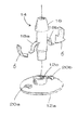
도 1a 내지 도 1d는 포트 부속 기구의 제 1 실시예를 나타낸 도면;
도 2a 및 도 2b는 포트 부속 기구의 제 2 실시예를 나타낸 도면;
도 3a 및 도 3b는 포트 부속 기구의 제 3 실시예를 나타낸 도면;
도 4a 및 도 4b는 포트 부속 기구의 제 4 실시예를 나타낸 도면;
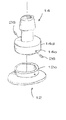
도 5a 및 도 5b는 포트 부속 기구의 제 5 실시예를 나타낸 도면;
도 6a 및 도 6b는 포트 부속 기구의 제 6 실시예를 나타낸 도면;
도 7a 및 도 7b는 포트 부속 기구의 제 7 실시예를 나타낸 도면;
도 8a 및 도 8b는 포트 부속 기구의 제 8 실시예를 나타낸 도면;
도 9a 내지 도 9f는 포트 부속 기구의 제 9 실시예를 나타낸 도면;
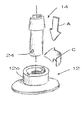
도 10은 포트 부속 기구의 제 10 실시예를 나타낸 도면;
도 11a 및 도 11b는 포트 부속 기구의 제 11 실시예를 나타낸 도면;
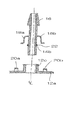
도 12a 내지 도 12c는 포트 부속 기구의 제 12 실시예를 나타낸 도면;
도 13a 및 도 13b는 포트 부속 기구의 제 13 실시예를 나타낸 도면;
도 14a 및 도 14b는 포트 부속 기구의 제 14 실시예를 나타낸 도면;
도 15a 내지 도 15d는 포트 부속 기구의 제 15 실시예를 나타낸 도면;
도 16은 포트 부속 기구의 제 16 실시예를 나타낸 도면;
도 17a 및 도 17b는 포트 부속 기구의 제 17 실시예를 나타낸 도면;
도 18a 내지 도 18c는 포트 부속 기구의 제 18 실시예를 나타낸 도면;
도 19는 포트 부속 기구의 제 19 실시예를 나타낸 도면; 그리고
도 20a 내지 도 20c는 포트 부속 기구의 제 20 실시예를 나타낸 도면.1 is a schematic view showing one possible embodiment of a container with a changeable port attachment;
1A-1D show a first embodiment of a port attachment mechanism;
2A and 2B show a second embodiment of the port attachment mechanism;
3A and 3B show a third embodiment of a port attachment mechanism;
4A and 4B show a fourth embodiment of the port attachment mechanism;
5A and 5B show a fifth embodiment of the port attachment mechanism;
6A and 6B show a sixth embodiment of the port attachment mechanism;
7A and 7B show a seventh embodiment of the port attachment mechanism;
8A and 8B show an eighth embodiment of the port attachment mechanism;
9A-9F show a ninth embodiment of the port attachment mechanism;
10 shows a tenth embodiment of a port attachment mechanism;
11A and 11B show an eleventh embodiment of the port attachment mechanism;
12A-12C show a twelfth embodiment of the port attachment mechanism;
13A and 13B show a thirteenth embodiment of the port attachment mechanism;
14A and 14B show a fourteenth embodiment of the port attachment mechanism;
15A-15D show a fifteenth embodiment of the port attachment mechanism;
16 shows a sixteenth embodiment of a port attachment mechanism;
17A and 17B show a seventeenth embodiment of the port attachment mechanism;
18A-18C show an eighteenth embodiment of the port attachment mechanism;
19 shows a nineteenth embodiment of a port attachment mechanism; And
20A-20C show a twentieth embodiment of a port attachment mechanism;
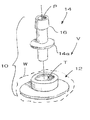
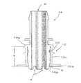
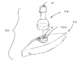
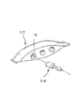
이하, 도 1을 참조하면, 본 발명의 일 태양에 따른 용기(V)용의 변경 가능한 포트 부속 기구(10)가 도시되어 있다. 바람직하게는, 상기 용기(V)는, 예를 들어, 생물학적 작용제, 약제학적 제제 등의 제조를 위한 살균 조건 하에서의 유체 처리(이로만 제한되는 것은 아니지만, 대용량 중간 저장, 세포 배양 재현탁, 바이러스 불활성화, 최종 제형, 최종 충전에 이용되거나 생물 반응기/발효기로서 이용되는 유형을 포함)에 사용되는 유형이다. 가장 바람직한 실시예에 있어서, 용기(V)는 가요성의 플라스틱 막으로 형성된 적어도 하나의 벽(W)을 포함하며, 이는 그 용기가 접을 수 있고 충전 시에 내부 저장실(I) 내의 유체에 의해 부여되는 형상에 맞춰질 수 있음을 의미한다. 이러한 재료는, 상당한 힘을 받으면 휘어질 수는 있지만 일반적으로 용기(V) 내로 도입되는 유체로 인해 형상이 변하지는 않는 강성 재료와는 구별된다.Referring now to FIG. 1, a changeable
용기(V)는 또한, 회전 가능한 또는 회전 불가능한 유형의 젓개(stirrer)를 포함할 수도 있지만 바람직하게는 살균 조건 하에서 유체를 교반할 수 있는 유형의 교반기를 포함할 수도 있다. 예를 들어, 이러한 구성 요소에는 자성 임펠러(M)가 포함될 수도 있는데, 이러한 자성 임펠러는 용기(V) 외부의 동력 장치와 비접촉 방식으로 결합하도록 구성됨으로써, 살균 특성의 유지 관점에서 문제를 야기할 수 있는 동적 시일(seal) 또는 유사 구조체를 필요로 하지 않는다. 대안으로서, 슬리브가 씌워진 회전 가능한 혼합기가 내부 저장실(I) 내로 도입되어 내부 저장실의 외부에 마련된 모터에 의해 구동될 수도 있다. 전술한 임펠러(M) 대신 또는 임펠러에 추가하여, 스파저(sparger)(도시하지 않음) 또는 그외 다른 장치가 소정 레벨의 유체 교반을 제공할 뿐만 아니라 내부 저장실 내의 액체와의 가스 교환를 촉진시키도록 사용될 수 있다. The vessel V may also include a rotatable or non-rotatable type of stirrer but preferably may also include a stirrer of the type capable of stirring the fluid under sterile conditions. For example, such a component may include a magnetic impeller (M), which is configured to engage in a non-contact manner with a power unit outside the vessel (V), thereby causing problems in terms of maintaining sterilization properties. It does not require dynamic seals or similar structures. Alternatively, a sleeved rotatable mixer may be introduced into the interior reservoir I and driven by a motor provided outside of the interior compartment. Instead of or in addition to the impeller M described above, a sparger (not shown) or other device may be used to provide a certain level of fluid agitation as well as to facilitate gas exchange with the liquid in the internal reservoir. Can be.
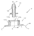
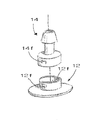
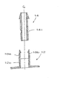
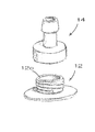
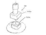
도 1을 계속 참조하면서 추가로 도 1a 및 도 1b를 참조하면, 부속 기구(10)는 포트(T)를 구비하며 어댑터(14)와 잠금 결합을 이루도록 구성되는 커넥터(12)를 포함한다. 본 발명에 있어서, 잠금 결합은, 마찰 끼워 맞춤 또는 억지 끼워 맞춤과 대비되는, 두 개의 부품이 기계적으로 접속되는 결합을 의미한다. 커넥터(12)는, 바람직하게는, 플라스틱과 같은, 용기(V)와 유사한 재료로 형성되며, 가장 바람직하게는, 벽(W)을 형성하는 재료보다 강성의 재료로 형성된다. 플랜지(12a)와 같은 둘레 연장부(도시된 바와 같이 디스크 형상으로 형성될 수도 있지만, 그외 다른 형태로 형성될 수도 있음; 도 20a 내지 도 20c 참조)가 또한, 벽(W)에 연결되도록 커넥터(12)를 따라, 보다 구체적으로, 커넥터의 내면 또는 외면을 따라 제공된다. 이러한 둘레 연장부의 연결이 용접 또는 그외 다른 유형의 부착 방법을 통해 이루어질 수도 있어, 포트(T)를 제외하고, 커넥터(12)와 대응 용기(V)의 사이에 유체 불투과성 시일이 형성된다.With further reference to FIGS. 1A and 1B, the
어댑터(14)는 유체를 전달할 수 있는 관형 통로(P)를 포함한다. 바람직하게는, 어댑터(14)는 포트(T)를 필요로 하는 특정 용도에 맞추어 구성된다. 예를 들어, 어댑터(14)는, 바람직하게는, 내부 저장실(I)의 외부로 연장되며, 배관의 길이 방향 개방 단부와 결합하기 위한 일 단부에, 미늘 형상 부분(barb)(16)과 같은 결합부를 포함한다. 또한, 바람직한 일 형태에 있어서, 어댑터(14)는 축 방향(X)으로 세장형으로 형성되며, 이에 따라 그에 비례하여 횡 방향 또는 측 방향(L)으로 보다 작은 직경을 갖는다.
본 발명의 일 태양에 따르면, 어댑터(14)는 변경 가능한 부속 기구(10)를 형성하도록 커넥터(12)와 잠금 결합을 이루기 위한 제 1 잠금 요소를 포함한다. 일 실시예에 있어서, 도 1b에 도시된 바와 같이, 어댑터(14)용 잠금 요소는 플랜지 형태의 둘레 돌출부(14a)를 포함한다. 도면으로부터 이해할 수 있는 바와 같이, 본 실시예에 있어서, 이와 같이 돌출부(14a)를 형성하는 플랜지는 적어도 부분적으로 커넥터(12) 내부의 포트(T)를 형성하는 직립 벽(12c)의 내부를 따라 형성되는 홈(12b)에 비해 크기가 크게 형성된다. 상기 홈(12b)은, 예를 들어, 환형 홈을 통해, 레지(ledge)를 형성하며, 돌출부(14a)는 대응하는 상보적인 에지를 포함한다. 결과적으로, 어댑터(14)의 잠금 요소의 역할을 하는 돌출부(14a)를 수동으로 가압하여 커넥터(12)의 상보적인 잠금 요소를 함께 형성하는 레지 및 홈(12b)과 결합시킴으로써 스냅 끼워 맞춤 결합이 이루어진다.According to one aspect of the invention, the
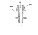
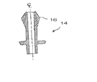
전술한 바와 같은 구조적 배치를 사용함으로써, 유리하게는, 특성이 서로 다르며 상이한 용도에 맞추어 사용될 수 있으면서도 신뢰성 있는 잠금 결합을 통해 커넥터(12)와 맞물리도록 유사한 구조로 형성되는 복수 개의 어댑터(14)를 제공할 수 있다. 예를 들어, 도 1b와 비교하면서 도 1c에 도시된 바를 참조하면, 어댑터(14)는 크기(길이 또는 직경)가 보다 큰 절두 원추형의 미늘 형상 부분(16)과 같은 결합부를 포함할 수도 있다. 도 1d에 도시된 바와 같이, 어댑터(14)는 미늘 형상 부분(16)과 같은 다른 형상의 결합부를 구비할 수도 있다.By using the structural arrangement as described above, advantageously, a plurality of
연결이 이루어지는 방식 면에서, 아래의 설명에서 보다 개요적으로 서술되고 있는 바와 같이, 용기(V)는 특정 고객의 요구를 수용하기 위한 상이한 다수의 어댑터 중 하나와 조합될 수도 있다. 이러한 조합 관계는 제조 공정 동안, 커넥터(12)가 포함되어 있는 용기(V)를 고객(예를 들어, 청정실 환경 하의)에게 전달하기 전에, 또는 심지어는 사용 시 현장에서 이루어질 수도 있다. 특정 어댑터(14)에 부합하는 기존 커넥터(12)를 구비한 용기를 개장(retrofit)할 수도 있으며, 또는 기존 어댑터를 커넥터에 대응하는 다른 어댑터로 교체할 수도 있다. 이에 따라, 전술한 어느 경우에나, 커넥터(12) 및 개구 포트(T)(도 1에 도시된 바와 같음)를 구비한 용기(V)가 비살균 조건 하에서 제조된 다음, 선택된 어댑터(14)(또는 어댑터들(14); 도 13a 및 도 13b 참조)와 결합될 수도 있다. 전술한 잠금 결합이 수동으로 구축될 수도 있으며, 따라서, 영구적인 연결을 이루기 위한 용접 등의 기계적 공정을 필요로 하지 않을 수도 있다. 이후, 어댑터(14)는 밀봉될 수도 있으며(예를 들어, 폐쇄 부재 또는 살균 필터를 구비한 배관 또는 클램프(도시하지 않음)을 사용하여), 이렇게 해서 얻어진 조립체는 살균 조건 하에서의 추후 사용을 위해 살균 처리된다. 이러한 방식으로, 용기(V)는 필요한 경우 특정 용도에 즉시 맞추어 질 수 이 있으며, 고객의 요구를 충족하도록 상이한 부속 기구를 구비한 다양한 유형의 용기의 비축을 필요로 하지 않을 수도 있다.In terms of how the connection is made, as described more generally in the description below, the container V may be combined with one of a number of different adapters to accommodate the needs of a particular customer. This combination may occur during the manufacturing process, prior to delivering the container V containing the
변경 가능한 포트 부속 기구(10)를 형성하기 위한 교체 가능한 어댑터(14)의 다양한 다른 실시예를 또한 고려할 수 있다. 예를 들어, 도 2a 및 도 2b를 참조하면, 어댑터(14)용의 제 1 잠금 요소가 암(arm)(18a, 18b) 형태의 적어도 두 개의 돌출부를 포함하는 둘레 잠금 요소를 포함하는 실시예가 도시되어 있다. 본 실시예에 있어서, 상기 암(18a, 18b)은 대체로 반경 방향으로 연장된다. 이들 암(18a, 18b)의 자유 단부는 커넥터(12)의 제 2 잠금 요소를 형성할 수도 있는 수용부(20a, 20b)에 삽입되도록 구성된다. 상기 수용부(20a, 20b)는 포트(T)를 형성하는 벽(12c)에 인접하여 커넥터(12)의 평면 상에 형성될 수도 있다. 암(18a, 18b)은 커넥터(12)에 삽입되기 전에 어댑터(14)의 몸체를 향해 내측으로(동작 화살표(B)로 지시된 방향) 구부러진 다음 이후 원상 회복될 수 있도록 충분한 가요성을 갖게 형성될 수도 있으며, 이에 따라, 고유의 스프링 작용에 의해 자유 단부가 수용부(20a, 20b)와 잠금 결합하도록 힘을 받게 된다.Various other embodiments of
본 실시예에 있어서, 커넥터(12)와 어댑터(14)는 밀봉 결합식으로 상호 맞물린다. 이는 글랜드(gland) 또는 가스켓(gasket)과 같은 밀봉 요소를 제공함으로써 달성될 수도 있다. 바람직하게는, 밀봉 요소는 어댑터(14) 상에 형성되는 환형 홈(14b)에 배치될 수도 있는 탄성 중합체 O-링(22)을 포함한다. 가장 바람직하게는, 밀봉 요소는 잠금 결합이 발생하는 장소와 상이한 위치에 제공됨으로써, 잠금 결합과 독립적으로 밀봉이 구축된다. 대안으로서, 그리고 아래의 설명을 읽음으로써 이해할 수 있는 바와 같이, O-링과 같은 밀봉 요소는 커넥터(12) 상에 제공될 수도 있다. 밀봉 요소는 도시된 바와 같이 제거 가능할 수도 있으며, 또는 커넥터(12) 또는 어댑터(14)가 일체형으로 형성될 수도 있다. 어느 경우에나, 이러한 배치에 의하면 바람직하게는 내부 저장실(I)과 대기 환경 사이의 살균 차단막이 형성된다.In this embodiment, the
베이어닛(bayonet) 끼워 맞춤의 특성을 이용한 잠금 결합의 다른 실시예가 도 3a 및 도 3b에 도시되어 있다. 도시된 구성에서, 어댑터(14)는 반경 방향 반대 방향으로 연장되는 한 쌍의 대향 러그(lug)(도 3a에는 단 하나의 러그(24)만 도시함)의 특성을 갖는 적어도 두 개의 돌출부를 포함하는 둘레 잠금 요소를 포함한다. 커넥터(12)의 대응 홈(12b)은 각각의 러그(24)를 수용하도록 구성되는 채널을 형성한다. 구체적으로, 각각의 채널의 제 1 세그먼트는 축 방향(X)으로 러그(24)를 수용하기 위해 벽(12c)의 레지를 따라 개방 단부를 포함한다. 제 1 세그먼트의 반대쪽 단부의 제 2 세그먼트는 둘레 방향으로, 바람직하게는, 대략 90°의 각도로 연장된다. 따라서, 도 3a를 다시 참조하면, 어댑터(14)는 잠금 결합을 구축하도록 축 방향(동작 화살표(A) 방향)으로 커넥터(12)에 의해 획정되는 포트(T) 내로 삽입된 다음, 둘레 방향(작동 화살표(C) 방향)으로 회전될 수도 있다. 밀봉 요소(도시하지 않음)가 또한 제공될 수도 있다.Another embodiment of a lock engagement using the characteristics of bayonet fit is shown in FIGS. 3A and 3B. In the configuration shown, the
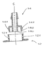
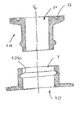
도 4a 및 도 4b에 도시된 다른 실시예에 따르면, 어댑터(14)는 동심의 내외벽(14c, 14d)을 포함한다. 내벽(14c)의 외경은 커넥터(12)의 벽(12c)의 내경보다 작으며, 외벽(14d)의 내경은 벽(12c)의 외경보다 크다. 따라서, 어댑터(14)는 상기 벽(12c)을 수용하기 위한 수용부(본 실시예에서, 환형 형상으로 형성됨)를 형성하도록 결합된 위치에서 벽(12c)을 덥도록 구성되어야 한다. 잠금 결합을 달성하기 위하여, 제거 가능한 체결구(26)(예를 들어, 장부촉(dowel), 설치 나사, 핀 등)와 같은 제 1 잠금 요소와 어댑터(14)의 제 2 잠금 요소가, 예를 들어, 커넥터(12)의 대응하는 수용부(12d)에 위치 설정되도록 외벽(14d)의 구멍(14e)을 관통하여 둘레 방향으로 체결구(26)를 삽입하는 등에 의해 결합될 수도 있다. 유밀 결합을 달성하기 위하여, O-링(22)과 같은 대응 밀봉 요소가 커넥터(12)에 형성된 홈(12e)에 안착되어, 어댑터(14) 상의 대응 표면과 맞물릴 수도 있다.According to another embodiment shown in FIGS. 4A and 4B, the
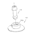
도 5a 및 도 5b의 실시예에 있어서, 어댑터(14)는 동심의 내외벽(14c, 14d)의 관점에서 유사한 구성으로 형성된다. 여기서, 외벽(14d)은 벽(12c)에 형성된 구멍(12e)과 같은 커넥터(12)의 대응하는 잠금 요소와 결합하기 위한 탭(tab)(14f) 형태의 적어도 두 개의 둘레 돌출부를 포함하는 잠금 요소를 포함한다. 바람직하게는, 상기 탭(14f)은 각각의 구멍(12f) 내측의 벽(12c)의 상면과 결합하기 위한 레지를 형성하도록 모따기 가공된다. 따라서, 어댑터(14)가 축 방향으로 커넥터(12) 내로 삽입될 때, 탭(14f)은 잠금 결합(적절한 밀봉 요소를 사용하여 액밀 상태로 이루어질 수도 있음)을 구축하도록 구멍(12f)과 정렬되어 형합될 수도 있다.In the embodiment of Figs. 5A and 5B, the
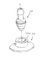
도 6a 및 도 6b에 도시된 변형예에 따르면, 어댑터(14)는 환형 비드(bead) 형태의 둘레 돌출부(14a)를 포함한다. 벽(12c)의 내면을 따라 형성되는 대응하는 환형 홈(12b)은 어댑터(14)의 대응하는 단부가 커넥터(12)의 포트(T)에 삽입되는 경우 비드와 결합되도록 구성된다. 이러한 결합에 의해 스냅 끼워 맞춤이 이루어질 수도 있다.According to the variant shown in FIGS. 6A and 6B, the
도 7a 및 도 7b에 도시된 다른 실시예에 따른 부속 기구(10)의 경우에는, 커넥터(12)의 벽(12c)이 잠금 결합 시에 어댑터(14)를 수용하도록 구성되는 컵 형상의 수용부를 형성하도록 배치된다. 구체적으로, 도시된 실시예에 있어서, 벽(12c)은 도 1a 및 도 1b에 도시된 바와 같이 규칙적인 형태로 형성되는 것이 아니라, 포트(T)의 일부를 형성하는 개구(O)를 형성하며, 또한 환형 레지를 형성하도록 반경 방향 내측으로 곡선형으로 형성된다. 레지에 대응하는 제 2 잠금 요소는 상기 개구(O)를 자유롭게 통과할 수 있는 크기의 보다 좁은 돌출 부분을 따른 영역을 제외하고 상기 개구에 비해 적어도 부분적으로 보다 큰 크기로 형성되는 둘레부를 구비한 어댑터(14) 상의 견부(14g)를 포함한다. 어댑터(14)는 견부(14g)의 크기가 보다 큰 부분을 따라 벽(12c)의 상부 단부에 의해 형성되는 레지와 완전히 결합하도록 구성되는 환형 노치(14h)를 추가로 포함한다. 따라서, 어댑터(14)가 축 방향으로 커넥터(12)의 수용부 내로 삽입되면, 도 7a에 도시된 바와 같이(동작 화살표(A) 방향), 잠금 결합이 구축된다(가능하다면 밀봉 요소를 사용하여).In the case of the
본 실시예에 있어서는, 어댑터(14)가 용기(V)의 내부 저장실(I)과 대면하는 커넥터(12)의 측면으로부터 설치된다는 점을 추가로 이해하여야 한다. 따라서, 커넥터(12)가 이미 용기(V)와 결합되어 있는 경우, 어댑터(14)의 삽입(예를 들어, 백의 경우, 이음매를 형성하도록, 예를 들어, 용접에 의해 궁극적으로 연결되는 가요성 막의 두 개의 단부 사이의 간극을 통한 삽입)을 허용하기 위해 개구가 남겨지도록 형성할 필요가 있다. 잠금 결합의 구축 시에, 어댑터(14)가 적소에 유지되어 소망하는 방식으로 밀봉되어 있는 상태에서 용기(V)의 밀봉 및 살균 작용이 진행될 수도 있다. 이러한 잠금 결합은 커넥터(12)가 용기(V)와 결합되기 전에 도 7a에 도시된 바와 같이 이루어질 수도 있다.In the present embodiment, it should be further understood that the
도 8a 및 도 8b에 도시된 실시예에 있어서, 커넥터(12)의 벽(12c)에 레지가 형성되어 있으며, 이 레지로부터 적어도 두 개의 대체로 평행한 암(18a, 18b)이 축 방향(X)으로 연장된다. 암(18a, 18b)은 대체로 180°의 간격으로 오프셋 되어 있으며, 내측으로 연장되는 반경 방향 돌출부를 포함한다. 이러한 돌출부는 어댑터(14)(이러한 어댑터의 크기는 벽(12c)의 내경보다 작은 외경을 갖도록 반대쪽 단부의 미늘 형상 부분(16)을 따라 형성되도록 결정됨)의 외면의 대응 위치에 형성되는 노치(14i)와 맞물리도록 구성된다. 따라서, 어댑터(14)는 소망하는 잠금 결합을 이루기 위해 노치(14i)에 암(18a, 18b)의 돌출부를 배치하도록 커넥터(12) 내로 삽입될 수도 있다.In the embodiment shown in FIGS. 8A and 8B, a ledge is formed in the
도 9a 내지 도 9d에는 도 7a 및 도 7b에 도시된 바와 개념적으로 유사한 실시예가 도시되어 있다. 본 실시예에 있어서, 어댑터(14)는 커넥터(12)를 수용하지만, 용기(V)의 내부 저장실(I) 외부 위치에 설치되도록 구성된다. 구체적으로, 벽(12c)은 크기가 보다 큰 견부(14g)에 형성된 노치와 결합하기 위한 레지를 형성하는 개구(O)를 구비한 컵 형상의 수용부를 형성한다. 도 9a 및 도 9b의 실시예에 있어서, O-링(22)과 같은 밀봉 요소가 어댑터(14)의 환형 홈(14b)에 제공된다. 따라서, 커넥터(12)와 어댑터(14)가 대응하는 노치(14h)와 레지 사이의 계면에 의해 잠금 결합되어 있는 경우, O-링(22)은 모든 측면에서 벽(12c)의 내면과 접촉하여, 살균 차단막을 형성할 수도 있는 유체 불투과성의 반경 방향 시일을 형성한다.9A-9D illustrate an embodiment conceptually similar to that shown in FIGS. 7A and 7B. In the present embodiment, the
대안으로서, 면 시일(face seal)이 사용될 수도 있다. 예를 들어, 상기 면 시일은 어댑터(14)의 대응하는 표면과 맞물리는 커넥터(12)의 표면을 따라, 예를 들어, 외측을 향하고 있는 둘레 플랜지를 따라 O-링과 같은 밀봉 요소를 제공함으로써 도 9c 및 도 9d에 도시된 바와 같이 달성될 수도 있다. 도시된 실시예에 있어서, 밀봉 요소 또는 O-링을 유지하기 위해 유사한 형상의 크기가 보다 큰 홈(12e)이 커넥터(12)에 제공될 수도 있다.As an alternative, a face seal may be used. For example, the face seal may be provided with a sealing element such as an O-ring along the surface of the
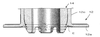
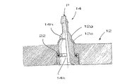
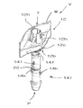
도 9e에는 도 7a 및 도 7b에 도시된 바와 개념적으로 유사한 실시예가 도시되어 있다. 본 실시예에 있어서, 어댑터(14)는 커넥터(12)를 수용하며 용기(V)의 내부 저장실(I) 외부 위치에 설치되도록 구성된다. 구체적으로, 직립 벽(12c)은 벽(12c)의 내향 플레어형 하부에 의해 형성되는 환형 레지와 결합하기 위한 노치를 형성하는 환형 견부(14g)에 의해 경계가 획정되는 개구(O)를 구비한 관형의 수용부를 형성하며, 상기 내향 플레어형 하부는 어댑터(14)의 하부 외부 윤곽과 형상이 실질적으로 일치하는 것이 바람직하다. 도 9f로부터 알 수 있는 바와 같이, 상기 내향 플레어형 부분은 어댑터(14)(그리고 바람직하게는 상기 내향 플레어형 부분보다 아래쪽의 어댑터(14)의 제 1 부분 및 상기 내향 플레어형 부분보다 위쪽의 어댑터(14)의 제 2 부분 모두)의 적어도 일부의 외경(do)보다 작은 내경(di)을 갖춘 측벽(12c)을 제공한다. 벽의 나머지 부분과 비교하여, 상기 내향 플레어형 부분의 가요성을 보다 더 증대시키기 위하여, 벽(14c)과 돌출부(12a)의 사이의 계면에 인접하여 둘레 방향으로 해제 홈(E), 절개부 또는 유사한 만입부가 제공될 수도 있다.9E illustrates an embodiment conceptually similar to that shown in FIGS. 7A and 7B. In this embodiment, the
어댑터(14)는, 선택적으로, 벽(12c)의 상부와 결합하기 위한, 예를 들어, 환형 플랜지(14a)와 같은, 둘레 돌출부(14a)를 포함할 수도 있다. 이 경우, 벽(12c)의 대응하는 상부에 맞물리는 상기 돌출부(14a)의 하면과 벽(12c)의 대응하는 하부에 맞물리는 견부(12g)에 의해 형성되는 노치 사이의 거리는 실질적으로 어댑터(14)의 대응하는 결합면 사이의 거리와 일치하여야 한다. O-링(22)과 같은 밀봉 요소가 어댑터(14)의 환형 홈(14b)에 제공된다.The
따라서, 커넥터(12)는 어댑터가 벽(12c)에 의해 형성되는 개방 단부를 통과하도록 함으로써 용기 외부의 위치로부터 어댑터(14)를 수용할 수도 있다. 어댑터(14)는 내부 통로를 통과하여 이동하도록 밀어 넣어짐으로써, 견부(14g)에 인접한 어댑터의 전단부가 벽(12c)의 내향 플레어형 말단부와 맞물려, 그 말단부가 홈(E)에 인접하여 외측으로 휘어지게 된다. 견부(14g)가 대응하는 노치가 벽(12c)의 하부 단부에 인접하게 되는 정도까지 통과하고 나면, 상기 말단부는 어댑터(14)의 외면과 맞물리도록 다시 스냅 방식으로 끼워진다(이에 따라, 스냅 끼워 맞춤이 형성된다). 어댑터(14)를 전진 이동시키고자 시도할 경우 벽(12c)의 내향 플레어형 하단부 바로 위쪽의 크기가 보다 큰 부분과의 사이에 발생하는 저항에 직면하게 되며, 어댑터(14)를 제거하고자 시도할 경우에도 견부(14g)의 노치와 상기 하단부의 맞물림에 의해 저항에 직면하게 된다는 점을 이해하여야 한다. 이 경우, 돌출부(14a)는 벽(12c)의 반대쪽 단부와 접촉 상태에 있으며, 따라서, 어댑터(14)의 전진 이동을 더욱 방지하는 역할을 한다. 커넥터(12)와 어댑터(14)가 견부(14g)에 의해 형성되는 대응하는 노치와 벽(12c)의 내향 플레어형 부분 사이의 계면에 의해 잠금 결합 상태에 있는 경우, O-링(22)이 살균 차단막을 형성할 수도 있는 유체 불투과성의 반경 방향 시일을 형성하도록 모든 측면에서 벽(12c)의 내면과 접촉한다. 이러한 방식으로 일단 결합되고 나면, 정합 거리(X)의 관점에서 양 단부에서의 맞물림의 조합으로 인해 어댑터(14)는 커넥터(12)의 관형 개구 내의 적소에 잠금 결합되며, 이에 따라 삽입 방향(즉, 축 방향(A))으로의 상대 이동이 방지된다. 또한, 어댑터(14)와 관형 벽(12c)의 내면 및 외면에 대응 부분들이 존재함에 따라, 조합된 부품 사이의 좌우 이동 및 상대적인 휨 작동이 방지되어, 잠금 결합이 의도하지 않게 풀리는 현상을 방지하는데 기여할 수 있다.Thus, the
도 9e에서, 어댑터(14)는 사용 시에 내부 저장실(I) 내로 커넥터(12)의 하면 아래로 돌출된다. 그러므로, 어댑터(14)의 하부에는 적어도 하나의, 바람직하게는 여러 개의 간극(H)이 마련되어 있으며, 이에 따라, 노치형으로 형성되거나 톱니 형상부를 구비하도록 형성된다. 이는 어댑터(14)가 관련 용기의 인접한 표면, 예를 들어, 백의 벽(W)에 대하여 유체 불투과성 시일을 형성하는 것을 방지하고, 또한, 보통 얇은 재료로 형성되는 상기 벽에 손상이 가는 것을 방지하는 것을 돕도록 원형의 또는 평활한 가장자리를 제공할 수도 있다. 대신, 내부 저장실(I) 내측의 배관과 연결되기 위한 미늘 형상 부분 또는 유사한 구조가 어댑터의 하부에 제공될 수도 있다.In FIG. 9E, the
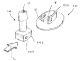
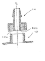
도 10의 실시예에 있어서는, 커넥터(12)의 벽(12c)이 측면 개구(S) 뿐만 아니라 포트(T)를 노출시키는 상부 개구(O)를 제공하도록 구성된다. 포트(T)로부터의 유체를 전달하기 위한 통로(P)의 일부를 포함하는 어댑터(14)의 부분(14j)은 벽(12c)의 내면에 대응하는 윤곽을 갖춘 둘레부를 구비한다. 따라서, 이러한 배치에 의하면, 어댑터(14)가 횡 방향 또는 측 방향(L)으로, 또는 선택적으로 축 방향으로 측면 개구(S)를 통과하여 삽입될 수 있다. 잠금 결합을 이루기 위하여, 어댑터(14)와 커넥터(12) 상에, 예를 들어, 벽(12c)의 대응하는 구멍(12f)과 결합하도록 구성되는 부분(14j)을 따라 탭(14f)과 같은 둘레 잠금 요소가 제공될 수도 있다. 잠금 결합 상태에서, 이러한 배치는 소망하는 유체 전달을 허용하기 위하여 커넥터(12)의 포트(T)가 어댑터(14)를 관통하여 연장되는 통로(P)와 정렬되어 일치되게 맞춰지도록 이루어지는 것이 바람직하다.In the embodiment of FIG. 10, the
도 11a 내지 도 11d에는 커넥터(12)와 어댑터(14)가 나사 체결되도록 구성되는 실시예가 도시되어 있다. 도 11a 및 도 11b에서, 어댑터(14)는 커넥터의 벽(12c)의 내면을 따라 형성되는 암형 나사부와 결합하기 위한 수형 나사부의 특성을 갖춘 둘레 잠금 요소를 포함한다. 도 11c 및 도 11d에는 이와 상반되는 구성이 도시되어 있다. 도 11d에서, 어댑터(14)의 내벽(14c)이 포트(T) 내로 연장되며, 이에 따라 딥 튜브(dip tube) 등과 같은 용기 내부의 구조체와 연결되도록 사용될 수도 있음에 주목하여야 한다.11A-11D, an embodiment is shown in which the
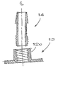
도 12a, 도 12b 및 도 12c에 도시된 어댑터(14)는 커넥터의 각종 형상의 벽(12c)에 대응하는 외벽(14d)을 포함할 수도 있다. 따라서, 도 12a에서, 벽(12c)의 단면 형상이 타원형인 경우 벽(14d) 또한 이에 대응하는 형상으로 형성된다. 도 12b에서, 벽(12c)의 단면 형상이 십자가형인 경우 벽(14d) 또한 이에 대응하는 형상으로 형성된다. 또한, 도 12c에서, 벽(12c)이 사각형인 경우 벽(14d) 또한 이에 대응하는 형상으로 형성된다. 사용 가능한 형상이 도시된 바와 같은 형상으로만 제한되는 것은 아니며, 연결을 구축하기 위해 어댑터(14)와 커넥터(12)를 서로 상대 회전시킬 필요가 없는 전술한 바와 같은 잠금 결합의 장점을 취할 수 있는 모든 형상이 사용될 수도 있음을 이해하여야 한다.The
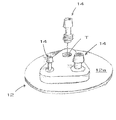
도 13a 및 도 13b에 도시된 실시예에 따르면, 커넥터(12)는 각기 어댑터(14)를 수용하기 위한 복수 개의 포트를 포함할 수도 있다. 따라서, 도 13a에서, 포트(T)는 플랜지(12a)를 포함하는 직사각형의 커넥터(12)를 따라 선형적으로 배치된다. 변경 능력은 서로 다른 어댑터(14)의 사용을 가능하게 한다(중앙 어댑터의 크기가 그 양측의 두 개의 어댑터의 크기와 상이함에 주목하여야 한다)는 점을 이해하여야 한다. 포트(T)가 선형적으로 배치되어야 하는 것은 아니며, 도 13b에 도시된 바와 같이 대응하는 플랜지(12a)를 구비한 커넥터(12)의 삼각형 배치와 같은 소정의 구성으로 배치될 수도 있다.According to the embodiment shown in FIGS. 13A and 13B, the
어댑터(14)는 필요하다면 대응하는 잠금 요소를 포함할 수도 있는 다양한 포트(T)를 구비한 커넥터(12)와 결합되도록 다양한 유형의 잠금 요소를 포함한다는 점에서 상이할 수도 있다. 따라서, 하나의 어댑터(14)는, 예를 들어, 도 6a에 도시된 바와 같은 제 1 유형의 잠금 요소를 포함할 수도 있으며, 제 2 어댑터는 도 5b에 도시된 바와 같은 상이한 제 2 잠금 요소를 포함할 수도 있다. 커넥터(12)는 동일할 수도 있으며, 또는 상이한 잠금 요소에 대응하도록 구성될 수도 있다. 오직 소정의 어댑터만이 다중 포트 커넥터(12)의 소정의 포트(T)에 대응하는 이러한 특정 유형의 구성에 의하면, 특정 유형의 어댑터가 미리 정해진 구성의 포트(T) 중 하나와 맞물리도록 하는 것을 보장할 수 있다.The
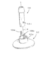
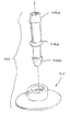
도 14a 및 도 14b에는, 소망하는 결합을 형성하며 선택적인 재구성을 허용하도록 대응하는 잠금 요소(예를 들어, 대응하는 홈(12b)과 결합하기 위한 환형 비드 형태의 돌출부(14a))를 구비한 커넥터(12)와 어댑터(14)가 도시되어 있다. 이러한 특정 구성에 있어서, 어댑터는 용기 외부의 구조체(예를 들어, 소정 길이의 배관)와 결합하기 위한 제 1 결합부 뿐만 아니라, 용기 내부의 구조체(도시하지 않음)와 결합하기 위한 제 2 결합부를 포함한다. 예를 들어, 도시된 실시예에 있어서, 어댑터(14)는 일 단부에 인접한 제 1 미늘 형상 부분(16a)과 타단부에 인접한 제 2 미늘 형상 부분(16b)을 포함하며, 이들 미늘 형상 부분은 비드(14a)와 홈(12b)의 사이에 잠금 결합이 구축되는 경우 포트(T) 또는 용기의 내부에 배치된다. 이해할 수 있는 바와 같이, 두 개의 결합부(예를 들어, 미늘 형상 부분(16a, 16b))는 직경이 상이한 배관과 같은 상이한 구조체를 수용하도록 상이한 크기 및 형상으로 형성될 수도 있다.14A and 14B are provided with corresponding locking elements (eg,
도 15a 내지 도 15d에서는 본 명세서에서 개시하는 개념이 관형 통로(P)와 적어도 하나의 미늘 형상 부분(16)을 구비한 어댑터(14) 이외의 구조체에 적용될 수도 있음을 보여주고 있다. 따라서, 도 15a 및 도 15b에 도시된 바와 같이, 어댑터(14)는 포트(T)를 밀봉하기 위한 밸브리스 폐쇄 부재 또는 플러그 형태로 형성될 수도 있다. 전술한 수단 중 어느 하나를 이용하여 잠금 결합이 구축될 수도 있으며, 도시된 실시예에 있어서, 잠금 결합은 커넥터의 대응하는 환형 홈(12b)과 결합하기 위한 돌출부(14a)로서 환형 비드 형태로 형성된다. 마찬가지로, 도 15c 및 도 15d에는 외부 공급원(통상, 백)으로부터 용기에 분말을 충전하도록 사용되는 크기가 큰 통로(P) 그리고 대응하는 클램프 등과 결합하도록 밀봉 요소와 맞물리는 표면 홈(G)(face groove)을 포함하는 어댑터(14)와 사용하기 위한 유사한 잠금 구성이 도시되어 있다.15A-15D show that the concepts disclosed herein may be applied to structures other than
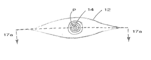
전술한 개념 중 어느 하나를 이용하여, 도 16에 도시된 바와 같은 보트 부속 기구(10)를 형성할 수도 있다. 여기서, 커넥터(12)는 보트(boat) 형상의 구조체를 포함하지만, 포트(T)를 형성하는 직립 벽(12c)을 여전히 포함할 수도 있다. 도시된 특정 실시예에 있어서, 어댑터(14)는 스냅 끼워 맞춤 결합 시에 벽(12c)의 상부 단부에 형성되는 대응하는 크기가 큰 레지와 맞물리는 내부 레지(통로(P)를 따라 점선으로 도시됨)를 포함한다. 그러나, 잠금 결합을 형성하기 위한 전술한 구성 중 어느 하나가 보트 형상의 부속 기구를 형성하도록 사용될 수도 있음을 이해하여야 한다.Using any of the above concepts, the
도 17a 및 도 17b에는, 크기가 큰 견부(12g)가 제공된 어댑터(14)의 노치(14h)와 결합하기 위한 레지를 형성하는 벽(12c)을 커넥터(12)가 포함하고 있는 보트 형상의 부속 기구(10)가 도시되어 있다. 본 실시예에 있어서, 커넥터(12)에 의해 형성되는 포트(T)는, 두 개의 구조체가 수용되는 경우, 포트에 수용되어 있는 어댑터(14)의 일부의 윤곽과 일치한다. O-링과 같은 밀봉 요소가 제공될 수도 있으며, 어댑터(14)의 수용된 부분의 대응하는 홈(14k)에 의해 유지된다.17A and 17B show a boat-shaped attachment in which the
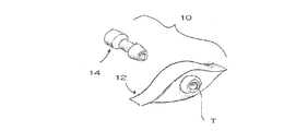
보트 형상의 부속 기구(10)는 도 18a 및 도 18b에 도시된 바와 같이 단일 포트(T)를 구비한 커넥터(12)를 포함할 수도 있음을 이해하여야 한다. 대안으로서, 도 18c에 도시된 바와 같이, 커넥터(12)는 각각 대응 잠금 요소를 구비한 복수 개의 상이한 어댑터 중 하나를 수용하도록 구성되는 복수 개의 포트(T)를 포함할 수도 있다. 포트(T)는 도시된 바와 같이 선형으로 배치될 수도 있으며, 또는 그외 다른 방식으로 배치될 수도 있다.It is to be understood that the boat shaped
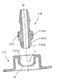
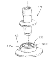
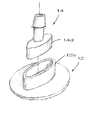
도 19에는, 포트(T)를 구비하며 잠금 결합 시에 커넥터와 맞물리도록 된 복수 개의 상이한 어댑터 중 하나와 함께 사용하기 위한 커넥터(12)를 포함하는 보트 형상의 부속 기구(10)의 변형예가 도시되어 있다. 도시된 바와 같이, 부속 기구(10)에 인접한 용기의 벽(W)이 도시되어 있지만, 반대쪽 벽은 명료성을 위해 제거되어 있다. 도시된 바로부터 알 수 있는 바와 같이, 커넥터(12)는 어댑터 상의 정렬 탭(14l)을 수용하는 크기의 한 쌍의 슬롯 형태의 홈(12b)을 구비한 벽(12c)을 포함한다. 어댑터(14)는 또한, 절두 원추형 구조체를 형성하는 대체로 곡선형의 쌍을 이룬 대향 벽(12h)에 의해 형성되는 레지와 같은, 용기 내부의 대응하는 구조체와 결합하는 탭(14f) 형태의 대향하는 둘레 돌출부를 추가로 포함한다.19 shows a variant of the boat-shaped
따라서, 어댑터(14)가 설치되는 경우, 정렬 탭(12b)은 잠금 요소로서의 역할을 수행하는 탭(14f)이 벽(12h)과 결합하여 소망하는 잠금 결합을 형성하는 것을 보장한다. 이러한 결합은 벽(12h)이 휘어지도록 하는 경향이 있어, 하나 이상의 보강 리브가 제공될 수도 있다. 필요한 경우, 다른 실시예에서와 같이, 유체가 포트(T)를 통해 통로(P)를 관통하여 자유롭게 유동할 수도 있다. 추가적으로, 벽(12h) 사이의 간극에 의해 유체가 통로(P)와 연통하는 어댑터(14)의 측면 배출구(141)를 통하여 인접한 공간으로부터 유동할 수 있다. O-링(22)과 같은 밀봉 요소가 또한 포트(T)를 따라 커넥터(12)의 내면과 맞물리도록 어댑터(12)를 따라 제공될 수도 있다.Thus, when the
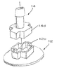
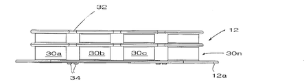
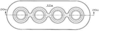
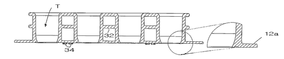
도 20a 내지 도 20c에는 각기 어댑터(도시하지 않음)를 수용하기 위한 포트(T)를 형성하는 복수 개의 직립형 구조체(30a 내지 30n)를 제공하는 단일 커넥터(12)를 포함하는 포트 부속 기구가 도시되어 있다. 커넥터(14)의 기부는 직사각형 플랜지를 포함한다. 사용된 어댑터는, 물론, 동일한 또는 상이한 구조로 형성될 수도 있으며, 커넥터(12)의 하면 아래에서 대응 용기의 내부 저장실 내로 연장되는 제 2 부분 및 구조체(30a 내지 30n)의 안착 표면과 결합되는 어댑터의 일부와 스냅 끼워 맞춤 잠금 결합을 형성하도록 도 9e에 도시된 유형으로 형성될 수도 있다. 구조체(30a 내지 30n)는 커넥터(32)에 의해 상호 연결될 수도 있다. 또한, 사용 시에 용기(V)의 내부 저장실(I)과 대면하는 측면을 따라 용기(V)의 표면과 커넥터(14)의 대응하는 표면 간의 고착 방지를 돕도록 돌출부(34)가 제공될 수도 있다.20A-20C show port attachments including a
본 발명의 다른 태양에 따르면, 복수 개의 상이한 어댑터가 커넥터와의 잠금 결합을 구축하도록 구성되며, 커넥터를 포함하는 용기를 구성하기 위한 키트의 일부로서 제공될 수도 있다. 어댑터는, 예를 들어, 상이한 크기 또는 형상(도 1c 및 도 1d 참조)을 구비한 미늘 형상 부분(16)과 같은 하나 이상의 결합부와 통로를 갖춘 관형 구조체를 포함할 수도 있다. 잠금 결합은 전술 및 도시된 바와 같은 다양한 유형으로 형성될 수도 있으며, 스냅 끼워 맞춤 결합, 나사 결합 그리고 베이어닛 끼움을 포함할 수도 있다. 비살균 용례에서, 이러한 유형의 결합이 또한, 용기(V)가 적용되는 용례에 따라 일 유형의 어댑터가 신속하게 해제되어 다른 유형의 어댑터로 대체될 수도 있다.According to another aspect of the invention, a plurality of different adapters are configured to establish a locking engagement with the connector and may be provided as part of a kit for constructing a container including the connector. The adapter may comprise a tubular structure with one or more engagement portions and passageways, such as, for example,
따라서, 상이한 어댑터와 잠금 결합을 형성하도록 된 커넥터를 각각 구비한 용기(예를 들어, 백)의 공급과 더불어, 그 상이한 복수 개의 어댑터를 포함한 키트가 제공될 수도 있다. 바람직하게는, 어댑터는 상이한 크기의 배관의 개방 단부와 결합하기 위한 능력 면에서 서로 차이가 나면서, 또한, 포함된 잠금 요소의 유형 면에서도 차이가 날 수도 있다. 이러한 키트에는 또한, 도 13a 내지 도 13c에 도시된 바와 같은 단일 커넥터(12)의 복수 개의 포트와 결합하기 위한 서로 다른 어댑터를 포함할 수도 있다. 가장 바람직하게는, 각각의 상이한 어댑터(14)는 내부 저장실(I) 내외로 유체를 전달하기 위한 관형 통로를 포함하지만, 사용되지 않는 포트 중 하나를 차단하기 위한 폐쇄 단부를 구비할 수 있다.Thus, in addition to the supply of containers (eg, bags) each having a connector adapted to form a lock engagement with a different adapter, a kit may be provided comprising the plurality of different adapters. Preferably, the adapters differ from each other in terms of their ability to engage with the open ends of differently sized tubing, and may also differ in terms of the type of locking elements involved. Such kits may also include different adapters for coupling with multiple ports of a
주문이 접수되면, 공급자는 고객의 특정 요구 또는 수요에 부합하도록 용기의 하나 이상의 커넥터(들)와 소망하는 어댑터(들)를 결합할 수도 있다. 유리하게는, 가열 또는 초음파 용접과 같은, 번거로우면서, 시간 소모적이고 비교적 값비싼 정밀 제조 기술을 사용하여 부속 기구(10)를 형성하는 것이 필요하지 않을 수도 있다. 또한, 주문이 이루어지기 전까지는 복수 개의 특정 구성의 용기를 저장하는 것이 불필요할 수도 있는데, 그 이유는 그 수요를 즉시 충족시킬 수 있기 때문이다. 현재 요구되고 있는 것보다 상당히 많은 수의 사전 살균 및 사전 제작 용기 재고를 저장할 필요가 없기 때문에, 창고 저장 및 추적 비용을 절감할 수 있다. 또한, 그 결과 제조 시간이 보다 짧아지고 특정 기술을 필요로 하지 않게 됨에 따라 용기를 완전 무결한 상태로 유지하는 것을 보장할 수 있으며, 이에 따라 또한 이러한 완전 무결 상태 점검을 위한 시험 횟수를 줄일 수 있다.Upon receipt of the order, the supplier may combine one or more connector (s) of the container with the desired adapter (s) to meet the customer's specific needs or demands. Advantageously, it may not be necessary to form the
전술한 소정 실시예의 경우(예를 들어, 도 1, 도 2, 도 5, 도 6, 도 7, 도 8 및 도 9에 도시된 실시예를 포함), 잠금 요소 중 하나 또는 모두가 깨지기 쉬운 방식으로 형성되어, 잠금 결합 해제시에 확실한 잠금 결합이 재구축되는 것을 방해하는 영구적인 변형을 초래할 수 있음을 알 수 있다. 이러한 구성에 있어서의 유리한 점은 어댑터와 커넥터가 재차 잠금 결합을 이루도록 재사용되는 것을 방지할 수 있다는 점이다. 또한, 밝혀진 바와 같이, 감마선과 같은 조사 에너지를 사용한 살균 공정은 어댑터(14)를 형성하도록 사용되는 플라스틱 재료(예를 들어, 가장 바람직한 실시예에 있어서는 고밀도 폴리프로필렌이지만, 폴리프로필렌, EVA, LDPE, LLDPE 등도 이용)가 조사 이전과 비교하여 보다 깨지기 쉬운 상태가 되도록 할 수도 있다. 그러므로, 어댑터(14)가 커넥터(12)에 배치되어 있으면서 보다 깨지기 쉬운 상태가 되는 경우, 후속 제거 작업이 이루어질 때 상당한 변형 또는 아마도 심지어 재료의 파괴가 야기될 수도 있으며, 이에 따라 어댑터가 부주의로 재사용되는 것을 방지할 수 있다.In the case of certain embodiments described above (including, for example, those shown in FIGS. 1, 2, 5, 6, 7, 8, and 9), one or both of the locking elements are fragile. It can be seen that it can cause a permanent deformation that prevents the secure lock engagement from rebuilding when the lock release. An advantage in this configuration is that the adapter and the connector can be prevented from being reused again to make a locking engagement. Also, as it turns out, the sterilization process using irradiation energy, such as gamma rays, is a plastic material used to form the adapter 14 (e.g., in the most preferred embodiment high density polypropylene, although polypropylene, EVA, LDPE, LLDPE, etc.) may be made more fragile than before. Therefore, if the
포트 부속 기구(10)를 구비한 용기를 형성하기 위해 사용되는 관련 방법이 또한 설명된다. 예를 들어, 용기를 형성하기 위한 방법은, 포트를 구비한 선택 커넥터를, 이 커넥터와의 잠금 결합을 구축하도록 각각 구성되며 관형 통로를 구비하는 복수 개의 상이한 어댑터 중 하나와 조합하는 단계를 포함할 수도 있다. 전술한 바와 같이, 이러한 조합 단계는 하나의 어댑터와 커넥터 사이의 잠금 결합을 형성하는 단계를 포함할 수도 있다. 포트를 구비한 적어도 하나의 커넥터를 각각 포함하는 복수 개의 용기 중 하나를 구성하기 위한 관련 방법은, 복수 개의 용기의 적어도 하나의 커넥터에 각각 대응하는 복수 개의 상이한 어댑터를 제공하는 단계를 포함한다. 전술한 단계 대신, 상기 방법은 또한, 용기 상의 복수 개의 포트를 포함하는 커넥터에 대응하는 복수 개의 상이한 어댑터 중 하나를 선택하는 단계와, 상기 선택된 어댑터를 커넥터와 조합하는 단계를 포함할 수도 있다. 대안으로서, 본 발명은 용기의 복수 개의 포트와 복수 개의 상이한 어댑터를 조합하는 단계를 포함할 수도 있다.A related method used to form a container with
본 발명의 다양한 실시예의 전술한 설명은 예시 및 서술의 목적으로 제공된 것으로, 이러한 서술 내용이 본 발명을 빠짐없이 설명할 의도나 본 발명을 개시된 특정 형태로만 제한할 의도가 있는 것은 아니다. 전술한 실시예는 본 발명의 원리 및 실시 용례를 최상의 방식으로 예시함으로써, 당 업계의 보통의 기술 수준을 가진 자로 하여금 본 발명을 고려되고 있는 특정 용도에 적합한 바와 같은 다양한 실시예 및 수정예로 활용할 수 있도록 한다.The foregoing descriptions of various embodiments of the present invention have been presented for purposes of illustration and description, and are not intended to be exhaustive or to limit the invention to the precise forms disclosed. The foregoing embodiments illustrate the principles and practice of the present invention in the best possible manner and are therefore utilized by those of ordinary skill in the art to various embodiments and modifications as are suitable for the particular use contemplated by the present invention. To help.
10 : 포트 부속 기구 12 : 커넥터
14 : 어댑터 16 : 미늘 형상 부분(barb)
22 : O-링 30a 내지 30n : 구조체
O : 개구 T : 포트
V : 용기 W : 벽10: port attachment mechanism 12: connector
14
22: O-
O: opening T: port
V: container W: wall
Claims (62)
유체를 수용하도록 구성되는 내부 저장실을 구비하며, 포트를 획정하는 제 1 벽과 제 1 잠금 요소가 마련된 커넥터를 포함하는 비살균 용기; 및
상기 제 1 벽의 내부에 삽입되도록 구성되는 제 1 단부 부분을 포함하며, 상기 포트를 통해 용기 내외로 유체를 전달하도록 구성되는 통로와 상기 커넥터의 제 1 잠금 요소와 잠금 결합을 형성하도록 구성되는 제 2 잠금 요소가 마련된 제 1 어댑터
를 포함하는 것을 특징으로 하는 장치.A device for forming a port fitment,
A non-sterile container having an internal reservoir configured to receive a fluid, said non-sterile container comprising a connector provided with a first wall and a first locking element defining a port; And
A first end portion configured to be inserted into the first wall and configured to form a lock coupling with a passage configured to transfer fluid into and out of the container through the port and a first locking element of the connector; 2nd first adapter with locking element
Apparatus comprising a.
배관과 연결되도록 구성되는 미늘 형상 부분, 커넥터의 포트를 밀봉하기 위한 밸브리스 플러그(valveless plug), 및 용기에 분말을 충전하거나 탐침을 수용하도록 구성되는 관형 이음쇠로 이루어진 그룹으로부터 선택되는 구조체를 포함하는 어댑터;
용기에 연결되도록 구성되며 포트를 포함하는 커넥터; 및
상기 커넥터와 어댑터 사이의 잠금 결합을 형성하기 위한 제 1 및 제 2 잠금 요소
를 포함하며, 상기 제 1 및 제 2 잠금 요소는 각각,
(a) 적어도 하나의 분리 가능한 체결구 및 이 체결구를 수용하기 위한 구멍과;
(b) 돌출부 및 이 돌출부와 결합하기 위한 노치를 구비한 둘레부를 포함하는 견부와;
(c) 적어도 하나의 러그 및 이 러그를 수용하도록 구성되는 채널과;
(d) 적어도 두 개의 암 및 각각의 암의 단부를 수용하기 위한 수용부; 그리고
(e) 커넥터의 둘레 레지로부터 축 방향으로 돌출되는 적어도 두 개의 암의 단부를 수용하기 위한 노치로 이루어진 그룹으로부터 선택되는 것을 특징으로 하는 장치.An apparatus for forming an accessory on a container,
A structure selected from the group consisting of a barbed portion configured to be connected with the tubing, a valveless plug for sealing the port of the connector, and a tubular fitting configured to fill the container with powder or receive the probe adapter;
A connector configured to be connected to the container and including a port; And
First and second locking elements for forming a locking engagement between the connector and the adapter
Wherein the first and second locking elements are each:
(a) at least one separable fastener and a hole for receiving the fastener;
(b) a shoulder comprising a protrusion and a circumference having a notch for engaging with the protrusion;
(c) at least one lug and a channel configured to receive the lug;
(d) a receptacle for receiving at least two arms and an end of each arm; And
(e) a device selected from the group consisting of notches for receiving ends of at least two arms protruding axially from the circumferential ledge of the connector.
유체를 수용하도록 구성되며, 내부 저장실로의 유체 접근을 제공하기 위한 관형 포트를 형성하는 커넥터를 포함하는 비살균 용기; 및
상기 내부 저장실 외부의 일 지점으로부터 삽입 방향으로 관형 포트 내로 삽입되도록 구성되어, 삽입 방향의 반대 방향으로의 이동이 방지되도록 커넥터와 스냅 끼워 맞춤되는 제 1 어댑터
를 포함하는 것을 특징으로 하는 장치.A device for forming a port attachment mechanism,
A non-sterile container configured to receive the fluid, the non-sterile container including a connector defining a tubular port for providing fluid access to the internal reservoir; And
A first adapter configured to be inserted into the tubular port in an insertion direction from one point outside the internal storage compartment, the first adapter being snap-fitted with the connector to prevent movement in an opposite direction of the insertion direction
Apparatus comprising a.
용기에 부착되도록 구성되며, 포트를 구비하고, 상기 포트에 인접하면서 측면 개구와 상부 개구를 형성하는 벽을 더 포함하는 커넥터; 및
상기 커넥터와 잠금 결합을 형성하기 위한 제 1 잠금 요소를 포함하는 어댑터
를 포함하는 것을 특징으로 하는 장치.A device combined with a container,
A connector configured to attach to the container, the connector further comprising a wall adjacent the port, the wall defining a side opening and an upper opening; And
An adapter comprising a first locking element for forming a locking engagement with the connector
Apparatus comprising a.
용기에 연결되도록 구성되며, 세장형의 대체로 직립형 측벽이 관형 포트를 형성하고 있는 커넥터; 및
상기 관형 포트의 내부로 삽입되도록 구성되는 제 1 부분을 포함하는 제 1 어댑터
를 포함하며, 상기 어댑터의 제 1 부분은 커넥터의 측벽의 적어도 제 1 부분의 내경보다 큰 제 1 외경을 구비하며, 어댑터의 제 2 부분은 상기 내경보다 큰 제 2 외경을 구비하는 것을 특징으로 하는 장치.An apparatus for forming a port attachment mechanism on a container,
A connector configured to be connected to the container, wherein the elongate generally upright sidewall forms a tubular port; And
A first adapter comprising a first portion configured to be inserted into the tubular port
Wherein the first portion of the adapter has a first outer diameter greater than the inner diameter of at least the first portion of the sidewall of the connector, and the second portion of the adapter has a second outer diameter greater than the inner diameter. Device.
상기 어댑터는 커넥터의 제 2 잠금 요소와 잠금 결합을 형성하기 위한 제 1 잠금 요소를 포함하는 것을 특징으로 하는 장치.50. The device of claim 49, further comprising a sealing element for forming a seal with the adapter,
And the adapter comprises a first locking element for forming a lock engagement with a second locking element of the connector.
(a) 적어도 하나의 분리 가능한 체결구 및 이 체결구를 수용하기 위한 구멍과;
(b) 돌출부 및 이 돌출부와 결합하기 위한 노치를 구비한 둘레부를 포함하는 견부와;
(c) 적어도 하나의 러그 및 이 러그를 수용하도록 구성되는 채널과;
(d) 적어도 두 개의 암 및 각각의 암의 단부를 수용하기 위한 수용부; 그리고
(e) 커넥터의 둘레 레지로부터 축 방향으로 돌출되는 적어도 두 개의 암의 단부를 수용하기 위한 노치로 이루어진 그룹으로부터 선택되는 것을 특징으로 하는 장치.The apparatus of claim 49, wherein the first locking element and the second locking element are:
(a) at least one separable fastener and a hole for receiving the fastener;
(b) a shoulder comprising a protrusion and a circumference having a notch for engaging with the protrusion;
(c) at least one lug and a channel configured to receive the lug;
(d) a receptacle for receiving at least two arms and an end of each arm; And
(e) a device selected from the group consisting of notches for receiving ends of at least two arms protruding axially from the circumferential ledge of the connector.
용기에 연결되도록 구성되며, 관형 포트를 형성하고 내향 플레어형 가요성 돌출부가 마련되어 있는 세장형의 대체로 직립형 측벽을 포함하는 커넥터; 및
상기 관형 포트의 내부로 삽입되도록 구성되며 상기 커넥터의 내향 플레어형 가요성 돌출부와 결합하도록 구성되는 크기가 큰 견부가 마련되어 있는 제 1 부분을 포함하는 제 1 어댑터
를 포함하는 것을 특징으로 하는 장치.An apparatus for forming a port attachment mechanism on a container having an internal reservoir,
A connector configured to connect to the container, the connector including an elongate generally upright sidewall defining a tubular port and provided with an inwardly flared flexible protrusion; And
A first adapter configured to be inserted into the tubular port and including a first portion having a large shoulder configured to engage an inwardly flared flexible protrusion of the connector
Apparatus comprising a.
용기에 연결하도록 구성되며, 관형 포트를 형성하고 제 1 잠금 요소가 마련되어 있는 세장형의 대체로 직립형 측벽을 포함하는 커넥터; 및
상기 관형 포트의 내부로 삽입되도록 구성되는 제 1 부분 및 이에 대체로 동심적으로 형성되는 제 2 부분을 포함하는 제 1 어댑터
를 포함하며, 상기 제 1 및 제 2 부분은 수용부를 형성하고, 상기 제 1 또는 제 2 부분 중 하나는 커넥터의 제 1 잠금 요소와 잠금 결합을 형성하기 위한 제 2 잠금 요소를 포함하는 것을 특징으로 하는 장치.An apparatus for forming a port attachment mechanism on a container,
A connector configured to connect to the container, the connector including an elongate generally upright sidewall forming a tubular port and provided with a first locking element; And
A first adapter comprising a first portion configured to be inserted into the tubular port and a second portion generally concentrically formed therewith
Wherein the first and second portions form a receptacle and one of the first or second portions comprises a second locking element for forming a lock engagement with the first locking element of the connector. Device.
살균 조건 하의 유체를 수용하도록 구성되는 내부 저장실을 구비하며, 제 1 잠금 요소가 마련된 커넥터를 포함하는 용기; 및
잠금 결합을 형성하도록 상기 커넥터의 제 1 잠금 요소에 연결되는 제 2 잠금 요소를 포함한 제 1 어댑터
를 포함하며, 잠금 결합이 깨지는 경우 제 1 또는 제 2 잠금 요소 중 하나가 살균 조건 하에서의 재사용을 방지하는 방식으로 변형되도록 구성되는 것을 특징으로 하는 장치.A device for forming a port attachment mechanism,
A container having an internal reservoir configured to receive a fluid under sterile conditions, the container including a connector provided with a first locking element; And
A first adapter comprising a second locking element connected to the first locking element of the connector to form a locking engagement
And wherein if the lock engagement is broken one of the first or second locking elements is configured to be modified in a manner to prevent reuse under sterile conditions.
(a) 적어도 하나의 분리 가능한 체결구 및 이 체결구를 수용하기 위한 구멍과;
(b) 돌출부 및 이 돌출부와 결합하기 위한 노치를 구비하며 크기가 크게 형성되는 둘레부를 포함하는 견부와;
(c) 적어도 두 개의 암 및 각각의 암의 단부를 수용하기 위한 수용부; 그리고
(d) 커넥터의 둘레 레지로부터 축 방향으로 돌출되는 적어도 두 개의 암의 단부를 수용하기 위한 노치로 이루어진 그룹으로부터 선택되는 것을 특징으로 하는 장치.59. The method of claim 56 wherein the first and second locking elements are:
(a) at least one separable fastener and a hole for receiving the fastener;
(b) a shoulder having a protrusion and a periphery having a large size and having a notch for engaging with the protrusion;
(c) a receptacle for receiving at least two arms and an end of each arm; And
(d) a device selected from the group consisting of notches for receiving ends of at least two arms protruding axially from the circumferential ledge of the connector.
복수 개의 관형 어댑터를 포함하며, 각각의 어댑터는 상기 관형 포트의 내부로 삽입되도록 구성되는 제 1 부분과, 커넥터의 제 1 잠금 요소와 잠금 결합을 형성하기 위한 제 2 잠금 요소를 포함하는 것을 특징으로 하는 키트.A kit for forming a port attachment mechanism on a container that includes a connector forming a tubular port and having a generally upright sidewall provided with a first locking element, the kit comprising:
A plurality of tubular adapters, each adapter including a first portion configured to be inserted into the tubular port, and a second locking element for forming a locking engagement with the first locking element of the connector; Kit.
상기 제 1 잠금 요소 및 제 2 잠금 요소는 각기,
(a) 적어도 하나의 분리 가능한 체결구 및 이 체결구를 수용하기 위한 구멍과;
(b) 돌출부 및 이 돌출부와 결합하기 위한 노치를 구비하며 크기가 크게 형성되는 둘레부를 포함하는 견부와;
(c) 적어도 하나의 러그 및 이 러그를 수용하도록 구성되는 채널과;
(d) 적어도 두 개의 암 및 각각의 암의 단부를 수용하기 위한 수용부; 그리고
(e) 커넥터의 둘레 레지로부터 축 방향으로 돌출되는 적어도 두 개의 암의 단부를 수용하기 위한 노치로 이루어진 그룹으로부터 선택되는 것을 특징으로 하는 키트.59. The device of claim 58, wherein each adapter includes a first locking element for engaging with a second locking element of the corresponding connector,
The first locking element and the second locking element are respectively,
(a) at least one separable fastener and a hole for receiving the fastener;
(b) a shoulder having a protrusion and a periphery having a large size and having a notch for engaging with the protrusion;
(c) at least one lug and a channel configured to receive the lug;
(d) a receptacle for receiving at least two arms and an end of each arm; And
(e) a kit selected from the group consisting of notches for receiving ends of at least two arms protruding axially from the circumferential ledge of the connector.
포트를 구비한 커넥터를 포함하는 비살균 용기를 제공하는 단계;
어댑터와 커넥터 사이의 잠금 결합을 형성하는 단계; 및
최종 사용자에게 용기를 운반하기 전에, 어댑터와 커넥터가 결합되어 있는 상태에서 용기를 살균 처리하는 단계
를 포함하는 것을 특징으로 하는 방법.A method of forming a sterile container for an end user,
Providing a non-sterile container comprising a connector having a port;
Forming a lock coupling between the adapter and the connector; And
Before transporting the container to the end user, sterilizing the container with the adapter and connector engaged.
≪ / RTI >
커넥터의 각각의 포트에 상이한 어댑터를 배치하는 단계를 더 포함하는 것을 특징으로 하는 방법.61. The apparatus of claim 60, wherein the connector comprises a plurality of ports,
Placing a different adapter in each port of the connector.
분리 시에, 어댑터 또는 커넥터 중 하나가 다시 잠금 결합을 형성할 수 없도록 구성되는 잠금 요소를 제공하는 단계를 더 포함하는 것을 특징으로 하는 방법.61. The apparatus of claim 60, wherein the connector includes a first locking element for engaging with a second locking element of the adapter to form a locking engagement,
And upon disconnection, providing a locking element that is configured such that one of the adapter or the connector cannot again form a locking engagement.
Applications Claiming Priority (2)
| Application Number | Priority Date | Filing Date | Title |
|---|---|---|---|
| US26726309P | 2009-12-07 | 2009-12-07 | |
| US61/267,263 | 2009-12-07 |
Publications (1)
| Publication Number | Publication Date |
|---|---|
| KR20120091437A true KR20120091437A (en) | 2012-08-17 |
Family
ID=44146140
Family Applications (1)
| Application Number | Title | Priority Date | Filing Date |
|---|---|---|---|
| KR20127017460A KR20120091437A (en) | 2009-12-07 | 2010-12-07 | Configurable port fitment, kit, and related methods |
Country Status (7)
| Country | Link |
|---|---|
| US (1) | US20120284991A1 (en) |
| EP (1) | EP2509882A4 (en) |
| KR (1) | KR20120091437A (en) |
| CN (1) | CN102725201B (en) |
| IN (1) | IN2012DN05239A (en) |
| SG (1) | SG181569A1 (en) |
| WO (1) | WO2011071897A2 (en) |
Families Citing this family (58)
| Publication number | Priority date | Publication date | Assignee | Title |
|---|---|---|---|---|
| FR2941385B1 (en) | 2009-01-23 | 2011-04-01 | Millipore Corp | METHOD FOR PROVIDING A CIRCUIT FOR BIOLOGICAL LIQUID AND CIRCUIT OBTAINED |
| FR2960795B1 (en) | 2010-06-08 | 2012-07-27 | Millipore Corp | DEVICE FOR A PLANT FOR TREATING BIOLOGICAL LIQUID |
| FR2960796B1 (en) | 2010-06-08 | 2014-01-24 | Millipore Corp | DEVICE FOR A PLANT FOR TREATING BIOLOGICAL LIQUID |
| FR2960794B1 (en) | 2010-06-08 | 2012-07-27 | Millipore Corp | DEVICE FOR A PLANT FOR TREATING BIOLOGICAL LIQUID |
| CH704476A1 (en) * | 2011-02-15 | 2012-08-15 | Alpla Werke | Plastic container with a spout. |
| EP3028648B1 (en) * | 2011-05-19 | 2019-07-10 | Terumo Puerto Rico L.L.C. | Procedural sheath adapter for vascular closure device |
| US20130084030A1 (en) * | 2011-10-03 | 2013-04-04 | Hyclone Laboratories, Inc. | Disposable plug and sensor fittings for bioreactor bags |
| FR2993572B1 (en) | 2012-07-23 | 2016-04-15 | Emd Millipore Corp | CIRCUIT FOR BIOLOGICAL LIQUID COMPRISING A PINCH VALVE |
| FR2993473B1 (en) * | 2012-07-23 | 2014-08-29 | Emd Millipore Corp | DEVICE FOR A PLANT FOR TREATING BIOLOGICAL LIQUID |
| WO2014055696A1 (en) * | 2012-10-02 | 2014-04-10 | Pedia Solutions Llc | Apparatus for oral delivery of fluids and semi-solid foods |
| WO2014061160A1 (en) * | 2012-10-19 | 2014-04-24 | 株式会社島津製作所 | Flow channel module and chromatograph provided with said flow channel module |
| USD720217S1 (en) | 2012-10-30 | 2014-12-30 | Performance Packaging Of Nevada, Llc | Flexible oral dispensing apparatus |
| US10391303B2 (en) * | 2013-03-14 | 2019-08-27 | Medtronic, Inc. | Tools and methods for implantation of implantable medical lead extensions or catheters |
| US9975658B2 (en) | 2013-06-05 | 2018-05-22 | Ge Healthcare Bio-Sciences Ab | Disposable container and mixing system comprising the container |
| US9795757B2 (en) * | 2013-06-28 | 2017-10-24 | Vyaire Medical Capital Llc | Fluid inlet adapter |
| JP2015051092A (en) * | 2013-09-06 | 2015-03-19 | 株式会社ジェイ・エム・エス | Double male connector |
| CN103674611A (en) * | 2013-11-25 | 2014-03-26 | 合浦果香园食品有限公司 | Aseptic sampling device and sampling method thereof |
| US10245609B2 (en) | 2013-11-26 | 2019-04-02 | Entegris, Inc. | Fitment and fitment adapter for dispensing systems and methods for manufacturing same |
| US11181496B2 (en) | 2013-12-06 | 2021-11-23 | Pendotech | Sensor fitting for biotech process bag |
| EP3076917B2 (en) | 2013-12-06 | 2021-06-02 | Pendo TECH | Sensor fitting for biotech process bag |
| US10557811B2 (en) | 2013-12-06 | 2020-02-11 | Pendotech | Sensor fitting for biotech process bag |
| MY177223A (en) * | 2014-01-10 | 2020-09-09 | Bayer Healthcare Llc | Single use disposable set connector |
| CH709307A1 (en) * | 2014-02-26 | 2015-08-28 | Tecan Trading Ag | Transport tool for transporting a laboratory article. |
| CN110368302B (en) * | 2014-04-21 | 2023-03-10 | 贝克顿迪金森有限公司 | Diaphragm device for use with closed system transfer device |
| US20170121084A1 (en) * | 2014-05-29 | 2017-05-04 | My Replenishment Inc. | Apparatus, system, and method for delivering refill liquid to a destination container |
| ES2549694B9 (en) * | 2014-10-23 | 2017-01-04 | Grifols, S.A. | ASEPTIC FILLING PROCEDURE OF A BAG |
| US9938996B2 (en) * | 2015-03-05 | 2018-04-10 | Snap-On Incorporated | Control button retention mechanism |
| US10309556B2 (en) | 2015-04-17 | 2019-06-04 | Saint-Gobain Performance Plastics Corporation | Sterile port connection |
| DE102015109849A1 (en) * | 2015-06-19 | 2016-12-22 | Aconity3D Gmbh | Bottom-up powder conveying mechanism for a PBLS plant, PBLS plant and process for converting and operating a PBLS plant |
| JP6604108B2 (en) | 2015-09-16 | 2019-11-13 | 株式会社スリーボンド | Viscous material supply apparatus and viscous material supply method |
| US9827582B2 (en) | 2015-11-04 | 2017-11-28 | Ecolab Usa Inc. | Refillable dispensing systems and components |
| KR20180002920U (en) * | 2016-01-29 | 2018-10-11 | 엔테그리스, 아이엔씨. | A sterilizable bag assembly by gamma irradiation |
| BR112018015107B1 (en) * | 2016-05-12 | 2022-02-01 | Hewlett-Packard Development Company, L.P | Outlet structure of building material container and building material container |
| US10785993B2 (en) | 2016-05-31 | 2020-09-29 | Taylor Commercial Foodservice, Llc | Valve assembly for a food product container of a food product dispensing machine |
| WO2018097738A1 (en) * | 2016-11-23 | 2018-05-31 | Fisher And Paykel Healthcare Limited | High flow luer connector |
| US11033459B2 (en) * | 2016-12-13 | 2021-06-15 | Shire Human Genetic Therapies, Inc. | Modular vial adapter |
| US11653682B2 (en) * | 2016-12-16 | 2023-05-23 | Steven Pippin | Apparatus and method for introducing a liquid into a sealed food package |
| EP3602503A4 (en) | 2017-07-10 | 2020-11-18 | Hewlett-Packard Development Company, L.P. | Associating object property data with locations |
| US10857397B2 (en) * | 2017-07-26 | 2020-12-08 | Honeywell International Inc. | Bayonet hose connector assembly mechanism in powered air purifying air respirator housing |
| DE102017117789A1 (en) * | 2017-08-04 | 2019-02-07 | Als Automated Lab Solutions Gmbh | Adapter for receiving a capillary and its use |
| EP3460037B1 (en) * | 2017-09-22 | 2022-03-23 | Sartorius Stedim Biotech GmbH | A device having multiple sterile fluid paths integrated onto a disposable container |
| AU2018345904A1 (en) * | 2017-10-06 | 2020-03-26 | Neomed, Inc. | Male to female coupling |
| DE102018103937A1 (en) * | 2018-02-21 | 2019-08-22 | Fresenius Medical Care Deutschland Gmbh | Device containing dialysis solution or dialysis solution concentrate |
| EP3587061A1 (en) | 2018-06-27 | 2020-01-01 | Resilux N.V. | Preform and container adapted for accommodating an insert piece, with methods and apparatus for their production |
| IL261024B2 (en) * | 2018-08-07 | 2023-07-01 | Equashield Medical Ltd | A septum holder with moveable septum |
| FR3085117B1 (en) * | 2018-08-22 | 2023-11-03 | Sartorius Stedim Biotech Gmbh | Disposable orifice device for connecting a functional unit to a flexible wall of a disposable container and method of manufacturing a disposable orifice device |
| US20200060593A1 (en) * | 2018-08-23 | 2020-02-27 | Becton, Dickinson And Company | Blood collection devices, systems, and methods |
| FR3087342B1 (en) * | 2018-10-17 | 2020-11-13 | Stemcis | JAR AND DEVICE FOR RECOVERING AND PREPARING ADIPOUS TISSUES |
| JP2022535611A (en) * | 2019-06-12 | 2022-08-09 | グローバル・ライフ・サイエンシズ・ソリューションズ・ユーエスエー・エルエルシー | Bioprocess Systems, Piping and Component Management Devices for Bioprocess Systems |
| JP7289938B2 (en) | 2019-06-28 | 2023-06-12 | フィリップ・モーリス・プロダクツ・ソシエテ・アノニム | Aerosol generator with single-use mouthpiece |
| CA3137852A1 (en) * | 2019-07-05 | 2021-01-14 | James W. Johnson | Probe |
| US11535421B2 (en) * | 2019-12-30 | 2022-12-27 | Global Life Sciences Solutions Usa Llc | System and method for packaging a bioprocessing bag and associated components, and packaging for a bioprocessing bag |
| EP3981867A1 (en) * | 2020-10-06 | 2022-04-13 | Lonza Cologne GmbH | Device for providing a cell suspension |
| CN113058154A (en) * | 2021-03-01 | 2021-07-02 | 河北医科大学第二医院 | Oral-nasal replacement kit for oral-nasal retention pipeline |
| US20230040059A1 (en) * | 2021-08-09 | 2023-02-09 | Ilc Dover Lp | Controlling a fluid flow |
| US20230122990A1 (en) * | 2021-10-14 | 2023-04-20 | Entegris, Inc. | Integrated aseptic system and method of making the same |
| WO2023183265A2 (en) * | 2022-03-24 | 2023-09-28 | Evolution Design & Development LLC | Configurable assembly for retaining and dispensing liquids |
| DE102022110499A1 (en) | 2022-04-29 | 2023-11-02 | Raumedic Ag | Bag for holding a medical or pharmaceutical medium, hose with a connector for connection to such a bag and arrangement with such a bag and with such a connector |
Family Cites Families (17)
| Publication number | Priority date | Publication date | Assignee | Title |
|---|---|---|---|---|
| DE324675C (en) * | 1919-10-09 | 1920-09-14 | Carl Steenken | Spray cork |
| US1549858A (en) * | 1924-11-13 | 1925-08-18 | William T Evans | Dispensing apparatus |
| US1567950A (en) * | 1925-08-14 | 1925-12-29 | Oliver B Frazier | Combination can opener and sealer |
| US2687831A (en) * | 1949-07-19 | 1954-08-31 | Formold Plastics Inc | Dispensing spout equipped container |
| US2762539A (en) * | 1952-09-26 | 1956-09-11 | Continental Can Co | Container arranged with a spout in one end |
| US2760683A (en) * | 1955-05-16 | 1956-08-28 | Owens Illinois Glass Co | Pouring spout |
| NL141453B (en) * | 1967-12-06 | 1974-03-15 | Guala Angelo Spa | CLOSURE FOR A BOTTLE. |
| US4150673A (en) * | 1977-02-03 | 1979-04-24 | Pharmachem Corporation | Coded entry system for blood bag |
| US5067639A (en) * | 1989-09-27 | 1991-11-26 | Maguire Paul R | Pouring spout which can be selectively opened and closed |
| US5000360A (en) * | 1989-09-27 | 1991-03-19 | John Lown | Pouring spout which can be selectively opened and closed |
| US5405333A (en) * | 1992-12-28 | 1995-04-11 | Richmond; Frank M. | Liquid medicament bag with needleless connector fitting using boat assembly |
| US5947937A (en) * | 1995-09-07 | 1999-09-07 | Sharon Ventures, Inc. | Method and apparatus for prevention of blood-type mismatches |
| US6086574A (en) * | 1997-11-21 | 2000-07-11 | Hyclone Laboratories, Inc. | Fluid delivery systems with diptube connector |
| AU2002217456A1 (en) * | 2000-12-20 | 2002-07-01 | Sankyo Seiyakukogyo Co., Ltd. | Adaptor for beverage pack and beverage feeder |
| EP1701780B8 (en) | 2004-01-07 | 2014-09-24 | Pall Technology UK limited | Bioprocessing vessel with integral sparger, and method of its manufacture |
| CN101677905B (en) * | 2007-06-08 | 2013-05-08 | 株式会社Jms | Female connector and connector |
| JP5133665B2 (en) * | 2007-11-30 | 2013-01-30 | 株式会社細川洋行 | Mouth for container, container provided with the same, sterilized container containing contents, and method for manufacturing the same |
-
2010
- 2010-12-07 SG SG2012042024A patent/SG181569A1/en unknown
- 2010-12-07 US US13/514,365 patent/US20120284991A1/en not_active Abandoned
- 2010-12-07 WO PCT/US2010/059253 patent/WO2011071897A2/en active Application Filing
- 2010-12-07 EP EP20100836529 patent/EP2509882A4/en not_active Withdrawn
- 2010-12-07 KR KR20127017460A patent/KR20120091437A/en not_active Application Discontinuation
- 2010-12-07 CN CN201080062789.3A patent/CN102725201B/en not_active Expired - Fee Related
- 2010-12-07 IN IN5239DEN2012 patent/IN2012DN05239A/en unknown
Also Published As
| Publication number | Publication date |
|---|---|
| CN102725201B (en) | 2015-06-10 |
| EP2509882A4 (en) | 2013-04-24 |
| CN102725201A (en) | 2012-10-10 |
| SG181569A1 (en) | 2012-07-30 |
| WO2011071897A2 (en) | 2011-06-16 |
| EP2509882A2 (en) | 2012-10-17 |
| IN2012DN05239A (en) | 2015-10-23 |
| WO2011071897A3 (en) | 2011-10-20 |
| US20120284991A1 (en) | 2012-11-15 |
Similar Documents
| Publication | Publication Date | Title |
|---|---|---|
| KR20120091437A (en) | Configurable port fitment, kit, and related methods | |
| CN107269995B (en) | Connector assembly, connector body, the method fluidly connected and fluid system | |
| JP5850376B2 (en) | Sensor probe seal | |
| US11357963B2 (en) | Aseptic coupling devices | |
| AU2014307860B2 (en) | Container for transporting and storing a liquid | |
| AU2010203591B2 (en) | Duckbill flip cap fitment for a collapsible container | |
| TWI414371B (en) | Drain connector for substance processing receptacle | |
| US20120260608A1 (en) | Drain connector for substance processing receptacle | |
| CN108980364B (en) | Discharge valve with rotatable angled outlet | |
| MX2011004264A (en) | Valve. | |
| US9341293B2 (en) | Connection having communication between biopharmaceutical containers and/or conduits | |
| AU2013388359B2 (en) | Container | |
| JP2020535086A (en) | Easy-to-remove cap design | |
| ES2902002T3 (en) | Head plate device, storage container device, cartridge arrangement, dispensing apparatus and its use | |
| JP2005518997A (en) | Self-sealing type appropriate amount supply tap of flexible package | |
| US20210024864A1 (en) | Multiport plate for a bioprocess bag | |
| US20210129152A1 (en) | Connector for Flexible Tubing | |
| US20240110142A1 (en) | Aseptic cell culture system and methods of use |
Legal Events
| Date | Code | Title | Description |
|---|---|---|---|
| WITN | Application deemed withdrawn, e.g. because no request for examination was filed or no examination fee was paid |