KR20120083915A - Determining touch data for one or more objects on a touch surface - Google Patents
Determining touch data for one or more objects on a touch surface Download PDFInfo
- Publication number
- KR20120083915A KR20120083915A KR1020127012818A KR20127012818A KR20120083915A KR 20120083915 A KR20120083915 A KR 20120083915A KR 1020127012818 A KR1020127012818 A KR 1020127012818A KR 20127012818 A KR20127012818 A KR 20127012818A KR 20120083915 A KR20120083915 A KR 20120083915A
- Authority
- KR
- South Korea
- Prior art keywords
- touch
- light
- signal
- touch surface
- projection
- Prior art date
Links
Images


Classifications
-
- G—PHYSICS
- G06—COMPUTING; CALCULATING OR COUNTING
- G06F—ELECTRIC DIGITAL DATA PROCESSING
- G06F3/00—Input arrangements for transferring data to be processed into a form capable of being handled by the computer; Output arrangements for transferring data from processing unit to output unit, e.g. interface arrangements
- G06F3/01—Input arrangements or combined input and output arrangements for interaction between user and computer
- G06F3/03—Arrangements for converting the position or the displacement of a member into a coded form
- G06F3/041—Digitisers, e.g. for touch screens or touch pads, characterised by the transducing means
- G06F3/0416—Control or interface arrangements specially adapted for digitisers
-
- G—PHYSICS
- G06—COMPUTING; CALCULATING OR COUNTING
- G06F—ELECTRIC DIGITAL DATA PROCESSING
- G06F3/00—Input arrangements for transferring data to be processed into a form capable of being handled by the computer; Output arrangements for transferring data from processing unit to output unit, e.g. interface arrangements
- G06F3/01—Input arrangements or combined input and output arrangements for interaction between user and computer
- G06F3/03—Arrangements for converting the position or the displacement of a member into a coded form
- G06F3/041—Digitisers, e.g. for touch screens or touch pads, characterised by the transducing means
- G06F3/042—Digitisers, e.g. for touch screens or touch pads, characterised by the transducing means by opto-electronic means
- G06F3/0421—Digitisers, e.g. for touch screens or touch pads, characterised by the transducing means by opto-electronic means by interrupting or reflecting a light beam, e.g. optical touch-screen
-
- G—PHYSICS
- G06—COMPUTING; CALCULATING OR COUNTING
- G06F—ELECTRIC DIGITAL DATA PROCESSING
- G06F2203/00—Indexing scheme relating to G06F3/00 - G06F3/048
- G06F2203/041—Indexing scheme relating to G06F3/041 - G06F3/045
- G06F2203/04109—FTIR in optical digitiser, i.e. touch detection by frustrating the total internal reflection within an optical waveguide due to changes of optical properties or deformation at the touch location
Landscapes
- Engineering & Computer Science (AREA)
- General Engineering & Computer Science (AREA)
- Theoretical Computer Science (AREA)
- Human Computer Interaction (AREA)
- Physics & Mathematics (AREA)
- General Physics & Mathematics (AREA)
- Position Input By Displaying (AREA)
- Length Measuring Devices By Optical Means (AREA)
Abstract
터치 감지 장치는, 인커플링 부위로부터 아웃커플링 부위로 터치면과 반대면 간의 내부 반사에 의해 광시트들이 진행되는 투광성 패널을 포함한다. 터치 감지 장치는 터치면을 터치하는 객체가 2개 이상의 광시트의 국부 감쇠를 야기하도록 구성된다. 광센서부가 전달되는 광에너지를 측정하기 위해 아웃커플링 부위와 광학적으로 연결된다. 데이터 처리기가 광센서부와 연결되며 터치 결정 과정을 수행하도록 구성된다. 상기 과정은 아웃커플링 부위 내의 광의 공간 분포를 나타내는 하나 이상의 투사 신호에 적용된다. 상기 과정에서는, 감쇠를 나타내는 신호 프로파일의 식별을 위해 투사 신호(들)을 처리한다(202 단계). 터치면 상의 하나 이상의 후보 터치 영역을 식별하기 위해 신호 프로파일을 사용한다(1206'단계). 이후, 하나 이상의 후보 터치 영역 내에서 2차원 분포된 신호값을 국부적으로 재구성하기 위해 투사 신호(들)을 처리하고(1207 단계), 후보 터치 영역 내에서 재구성된 신호값을 처리함으로써, 상기 또는 각각의 객체에 대한 터치 데이터를 결정한다(1208 단계).The touch sensing device includes a translucent panel through which light sheets travel by internal reflection between the touch surface and the opposite surface from the incoupling portion to the outcoupling portion. The touch sensing device is configured such that an object touching the touch surface causes local attenuation of two or more light sheets. The optical sensor unit is optically connected to the outcoupling site to measure the transmitted light energy. The data processor is connected to the optical sensor unit and configured to perform a touch determination process. The process is applied to one or more projection signals representing the spatial distribution of light in the outcoupling site. In this process, the projection signal (s) are processed (step 202) to identify a signal profile indicating attenuation. The signal profile is used to identify one or more candidate touch areas on the touch surface (step 1206 '). The projection signal (s) are then processed (step 1207) to locally reconstruct the two-dimensionally distributed signal values within the one or more candidate touch regions, and by processing the signal values reconstructed within the candidate touch regions, respectively or above. In operation 1208, the touch data is determined for the object.
Description
관련 출원에 대한 상호 참조Cross-reference to related application
본 출원은 2009년 10월 19일자로 출원된 스웨덴 특허출원번호 제0950768-2호 및 2009년 10월 19일자로 출원된 미국 가출원번호 제61/272,665호의 이익을 주장하며, 양자의 개시내용이 본원에 참조로서 통합된다.This application claims the benefit of Swedish Patent Application No. 0950768-2, filed October 19, 2009 and US Provisional Application No. 61 / 272,665, filed October 19, 2009, the disclosures of which are incorporated herein by reference. Is incorporated by reference.
본 발명은 터치 감지 패널 및 상기 패널과 관련된 데이터 처리 기법에 관한 것이다.The present invention relates to a touch sensitive panel and a data processing technique associated with the panel.
터치 감지 패널은 컴퓨터, 전자 측정 및 검사 장비, 게임 장치 등에 입력 데이터를 제공하기 위해 사용이 증가하고 있다. 패널은 사용자가 예컨대 포인터, 스타일러스, 또는 하나 이상의 손가락을 이용하여 상호작용할 수 있도록 그래픽 사용자 인터페이스(GUI)를 구비할 수 있다. GUI는 고정 인터페이스이거나 동적 인터페이스일 수 있다. 고정 GUI는 예컨대 패널의 위, 아래, 또는 내부에 배치되는 인쇄물의 형태일 수 있다. 동적 GUI는, 패널에 통합되거나 패널 아래에 배치되는 디스플레이 스크린에 의해 제공되거나, 또는 프로젝터에 의해 패널에 투사되는 영상에 의해 제공될 수 있다.Touch sensing panels are increasingly being used to provide input data to computers, electronic measurement and inspection equipment, and gaming devices. The panel may have a graphical user interface (GUI) such that the user can interact with, for example, a pointer, stylus, or one or more fingers. The GUI may be a fixed interface or a dynamic interface. The stationary GUI may be in the form of a print placed for example above, below, or inside the panel. The dynamic GUI may be provided by a display screen integrated into or disposed under the panel, or by an image projected onto the panel by the projector.
예컨대, 카메라를 이용하여 패널 상의 터치점(들)에서 산란된 광을 캡쳐하거나, 또는 패널에 저항성 와이어 그리드, 용량성 센서, 스트레인 게이지 등을 통합함으로써 패널에 터치 감도를 제공하는 다수의 기법이 주지되어 있다.For example, many techniques for providing touch sensitivity to a panel by capturing light scattered at touch point (s) on the panel using a camera, or by incorporating a resistive wire grid, capacitive sensor, strain gauge, and the like, are well known. It is.
US2004/0252091호에는 전반사장애(Frustrated Total Internal Reflection, FTIR)를 기반으로 하는 대안적인 기법이 기재되어 있다. 광은 패널에 커플링되어, 내부 전반사에 의해 패널 내부에서 진행된다. 광센서 어레이가 패널의 주변부에 위치되어 광을 검출한다. 객체가 패널의 표면과 접촉하게 되는 경우, 광은 터치점에서 국부 감쇠될 것이다. 객체의 위치는 광센서 어레이에서 각 광원의 광의 감쇠를 기반으로 삼각측량법(triangulation)에 의해 결정된다.US2004 / 0252091 describes an alternative technique based on Frustrated Total Internal Reflection (FTIR). Light is coupled to the panel and propagates inside the panel by total internal reflection. An array of photosensors is located at the periphery of the panel to detect light. If the object comes in contact with the surface of the panel, the light will be locally attenuated at the touch point. The position of the object is determined by triangulation based on the attenuation of the light of each light source in the photosensor array.
US2009/0153519호에는 신호를 전달할 수 있는 패널이 기재되어 있다. 단층촬영 장치가 패널에 인접하게 위치되고, 신호 흐름 포트들이 이격된 위치에서 패널의 가장자리 주위에 배치된다. 신호 흐름 포트에서 측정된 신호는 패널 상에 전도성의 2차원 표현을 생성하도록 단층촬영 처리되고, 그에 따라 패널면을 터치하는 객체가 검출될 수 있다. 예컨대, 주지의 여과후 역투사(filtered backprojection) 알고리즘을 이용한 단층촬영 재구성은 처리집약적인 연산이다. 그러므로, 단층촬영 재구성은 특히 고해상도의 2차원 표현이 요구되는 경우 상당한 처리 시간을 필요로 할 수 있다. US2009 / 0153519 describes a panel capable of transmitting signals. A tomography device is located adjacent to the panel, and signal flow ports are disposed around the edge of the panel at a spaced position. The signal measured at the signal flow port is tomographically processed to produce a two dimensional representation of the conductivity on the panel, whereby an object touching the panel surface can be detected. For example, tomography reconstruction using a known filtered backprojection algorithm is a process intensive operation. Therefore, tomographic reconstruction may require significant processing time, especially when high resolution two dimensional representations are required.
본 발명의 목적은 종래 기술의 하나 이상의 한계를 적어도 부분적으로 극복하는 데에 있다.It is an object of the present invention to at least partially overcome one or more limitations of the prior art.
후술하는 설명에 의해 명백해질 수 있는 상기한 목적 및 다른 목적은 독립항에 따른 방법, 컴퓨터 프로그램 제품, 위치 결정 장치, 및 터치 감지 장치에 의해 적어도 부분적으로 달성되고, 실시형태들은 종속항에 의해 정의된다.The foregoing and other objects, which may be made apparent by the description which follows, are at least partly achieved by a method, a computer program product, a positioning device, and a touch sensing device according to the independent claims, and embodiments are defined by the dependent claims. .
본 발명의 제1 양상은 터치 감지 장치의 방법이다. 상기 장치는, 터치면 및 반대면이 정의된 투광성 패널, 및 인커플링 부위로부터 아웃커플링 부위로 터치면과 반대면 간의 내부 반사에 의해 진행되는 광을 각각 포함하는 광시트들을 패널의 내부에 제공하는 광원부를 포함하고, 아웃커플링 부위에 도달하는 광을 검출하는 광센서부를 더 포함하며, 터치면을 터치하는 하나 이상의 객체가 2개 이상의 광시트의 국부 감쇠를 야기하도록 구성된다. 상기 방법은: 상기 아웃커플링 부위 내의 광의 공간 분포를 나타내는 하나 이상의 투사 신호를 획득하는 단계; 상기 감쇠를 나타내는 신호 프로파일의 식별을 위해 상기 하나 이상의 투사 신호를 처리하는 단계; 신호 프로파일에 기반하여 터치면 상의 하나 이상의 후보 터치 영역을 식별하는 단계; 상기 하나 이상의 후보 터치 영역 내에서 2차원 분포된 신호값을 재구성하기 위해 상기 하나 이상의 투사 신호를 처리하는 단계; 및 후보 터치 영역 내에서 재구성된 신호값을 처리함으로써 상기 또는 각각의 객체에 대한 터치 데이터를 결정하는 단계를 포함한다.A first aspect of the invention is a method of a touch sensitive device. The apparatus includes a light-transmitting panel having a touch surface and an opposite surface defined therein, and optical sheets each including light propagated by internal reflection between the touch surface and the opposite surface from the incoupling portion to the outcoupling portion. And a light sensor portion for detecting light reaching the outcoupling portion, wherein the one or more objects touching the touch surface are configured to cause local attenuation of the two or more light sheets. The method includes: obtaining one or more projection signals indicative of a spatial distribution of light in the outcoupling site; Processing the one or more projection signals to identify a signal profile indicative of the attenuation; Identifying one or more candidate touch regions on the touch surface based on the signal profile; Processing the one or more projection signals to reconstruct a two dimensional distributed signal value within the one or more candidate touch regions; And determining touch data for the or each object by processing the reconstructed signal value in the candidate touch area.
일 실시형태에서, 식별 단계는: 각각의 신호 프로파일에 대해, 터치면을 가로질러 신호 프로파일에 기반하여 결정된 폭을 가진 감쇠 경로를 결정하는 단계; 및 터치면 상의 상기 하나 이상의 후보 터치 영역을 결정된 감쇠 경로 세트의 함수로 식별하는 단계를 포함한다.In one embodiment, the identifying step comprises: for each signal profile, determining an attenuation path having a width determined based on the signal profile across the touch surface; And identifying the one or more candidate touch areas on the touch surface as a function of the determined set of attenuation paths.
일 실시형태에서, 식별 단계는 감쇠 경로들을 교차시키는 단계를 포함한다. 이러한 실시형태에서, 획득 단계는, 복수의 투사 신호를 획득하는 단계로, 각각의 투사 신호는 투사 신호가 터치면을 터치하는 객체에 반응하지 않는 터치면 상의 데드존 세트와 연관되는 단계를 포함할 수 있고, 식별 단계는 감쇠 경로를 데드존과 교차시키는 단계를 더 포함한다.In one embodiment, the identifying step includes crossing the attenuation paths. In this embodiment, the acquiring step includes acquiring a plurality of projection signals, each projection signal comprising a set of dead zones on a touch surface on which the projection signal does not respond to an object touching the touch surface. The identifying may further comprise crossing the attenuation path with the dead zone.
일 실시형태에서, 획득 단계는 복수의 투사 신호를 획득하는 단계를 포함하고, 식별 단계는: 각각의 투사 신호에 대해, 터치면 상의 관련 감쇠 경로의 위치를 나타내는 경로맵을 생성하는 단계; 및 생성된 경로맵들을 교차시키는 단계를 포함한다. 이러한 실시형태에서, 각각의 경로맵은 상기 광시트들 중 하나와 연관될 수 있고, 식별 단계는: 연관된 시트 내의 광선 간의 각도를 최소화하기 위해 경로맵 쌍을 형성하는 단계; 및 상기 경로맵 쌍들을 교차시키는 단계를 포함할 수 있다.In one embodiment, the acquiring step includes acquiring a plurality of projection signals, and the identifying step includes: generating, for each projection signal, a path map indicating the location of the associated attenuation path on the touch surface; And crossing the generated route maps. In this embodiment, each pathmap may be associated with one of the lightsheets, and the identifying step may include: forming a pathmap pair to minimize the angle between the rays in the associated sheet; And crossing the route map pairs.
일 실시형태에서, 획득 단계는 복수의 투사 신호를 획득하는 단계를 포함하고, 식별 단계는: 투사 신호 쌍들에 대해, 투사 신호 쌍에 대해 결정된 감쇠 경로들의 교차점을 나타내는 경로맵을 생성하는 단계; 및 생성된 경로맵들을 교차시키는 단계를 포함한다. 이러한 실시형태에서, 각각의 투사 신호는 상기 광시트들 중 하나와 연관될 수 있고, 식별 단계는 연관된 시트 내의 광선 간의 각도를 최대화하기 위해 상기 투사 신호 쌍을 형성하는 단계를 포함할 수 있다. 이러한 실시형태에서, 교차 단계는 경로맵들을 기하학적으로 정렬하여 논리곱 연산(logical AND operation)을 수행하는 단계를 수반할 수 있다. 각각의 경로맵은 투사 신호가 터치면을 터치하는 객체에 반응하지 않는 터치면 상의 데드존의 위치를 더 나타낼 수 있다.In one embodiment, the acquiring step includes acquiring a plurality of projection signals, wherein the identifying step includes: generating, for the projection signal pairs, a path map indicating the intersection of the attenuation paths determined for the projection signal pair; And crossing the generated route maps. In such an embodiment, each projection signal may be associated with one of the lightsheets, and the identifying step may include forming the projection signal pair to maximize the angle between the rays in the associated sheet. In such an embodiment, the intersecting step may involve geometrically aligning the pathmaps to perform a logical AND operation. Each path map may further indicate the position of the dead zone on the touch surface where the projection signal does not respond to the object touching the touch surface.
일 실시형태에서, 감쇠 경로를 결정하는 단계는: 신호 프로파일의 한계를 결정하는 단계; 터치면을 가로질러 신호 프로파일에 대응하는 광경로를 식별하는 단계; 및 식별된 광경로에 기반하여 터치면을 가로질러 한계를 재추적하는 단계를 포함한다. 이러한 실시형태에서, 한계를 재추적하는 단계는, 광산란으로 인한 신호 프로파일 폭의 인커플링 부위까지의 거리에 대한 의존성을 나타내는 소정의 폭함수를 적용하는 단계를 포함할 수 있다. 일 실시형태에서, 광산란은 터치면과 반대면 중 적어도 하나에 의해 야기된다. 폭함수는 신호 프로파일의 폭이 주어진 객체의 실제 폭을 인커플링 부위까지의 거리의 함수로 나타낼 수 있다.In one embodiment, determining the attenuation path comprises: determining a limit of a signal profile; Identifying a lightpath corresponding to the signal profile across the touch surface; And retracking the limit across the touch surface based on the identified light path. In such embodiments, retracking the limit may include applying a predetermined width function that indicates a dependency of the signal profile width due to light scattering on the distance to the incoupling site. In one embodiment, the light scattering is caused by at least one of the touch surface and the opposite surface. The width function can represent the actual width of the object given the width of the signal profile as a function of the distance to the incoupling site.
일 실시형태에서, 감쇠 경로를 결정하는 단계는 각각의 감쇠 경로를 다각형, 바람직하게는 볼록 다각형에 의해 나타내는 단계를 포함한다.In one embodiment, determining the attenuation path includes representing each attenuation path by a polygon, preferably a convex polygon.
일 실시형태에서, 광시트들은, 제1 광빔 세트가 제1 주요 방향으로 터치면을 가로질러 스위핑되도록 제1 광빔 세트를 제1 인커플링 부위를 따라 스위핑하고, 제2 광빔 세트가 제2 주요 방향으로 터치면을 가로질러 스위핑되도록 제2 광빔 세트를 제2 인커플링 부위를 따라 스위핑함으로써 생성된다.In one embodiment, the lightsheets sweep the first set of light beams along the first incoupling portion such that the first set of light beams are swept across the touch surface in a first major direction, and the second set of light beams is second major. Generated by sweeping the second set of light beams along the second incoupling portion to be swept across the touch surface in a direction.
일 실시형태에서, 광시트들은 각각의 인커플링 부위로부터 멀어지는 방향으로 터치면의 평면에서 확장되는 빔의 형태로 생성된다.In one embodiment, the lightsheets are produced in the form of a beam extending in the plane of the touch surface in a direction away from each incoupling site.
일 실시형태에서, 각각의 투사 신호는 광시트들 중 하나와 연관된다.In one embodiment, each projection signal is associated with one of the light sheets.
일 실시형태에서, 투사 신호를 획득하는 단계는, 아웃커플링 부위 내의 광에너지의 공간 분포를 나타내는 에너지 신호를 획득하고, 객체가 터치면을 터치함 없이 아웃커플링 부위 내의 광에너지의 공간 분포를 나타내는 백그라운드 신호에 의해 상기 에너지 신호를 정규화하는 단계를 포함한다.In one embodiment, the step of obtaining a projection signal obtains an energy signal representing a spatial distribution of light energy in the outcoupling site, and obtains a spatial distribution of light energy in the outcoupling site without the object touching the touch surface. Normalizing the energy signal by the representative background signal.
본 발명의 제2 양상은 데이터 처리 시스템에서 실행되는 경우 제1 양상의 방법을 수행하도록 구성된 컴퓨터 코드를 포함하는 컴퓨터 프로그램 제품이다.A second aspect of the present invention is a computer program product comprising computer code configured to perform the method of the first aspect when executed in a data processing system.
본 발명의 제3 양상은 터치 감지 장치에 구비되는 터치면 상의 하나 이상의 객체에 대한 터치 데이터를 결정하는 장치이다. 상기 장치는, 아웃커플링 부위 내의 광의 공간 분포를 나타내는 하나 이상의 투사 신호를 획득하는 요소; 감쇠를 나타내는 신호 프로파일의 식별을 위해 상기 하나 이상의 투사 신호를 처리하는 요소; 신호 프로파일에 기반하여 터치면 상의 하나 이상의 후보 터치 영역을 식별하는 요소; 상기 하나 이상의 후보 터치 영역 내에서 2차원 분포된 신호값을 재구성하기 위해 상기 하나 이상의 투사 신호를 처리하는 요소; 및 후보 터치 영역 내에서 재구성된 신호값을 처리함으로써 상기 또는 각각의 객체에 대한 터치 데이터를 결정하는 요소를 포함한다.A third aspect of the present invention is an apparatus for determining touch data for one or more objects on a touch surface provided in a touch sensing device. The apparatus comprises: an element for obtaining one or more projection signals indicative of the spatial distribution of light in the outcoupling site; An element for processing the one or more projection signals to identify a signal profile indicative of attenuation; An element identifying one or more candidate touch regions on the touch surface based on the signal profile; An element for processing the one or more projection signals to reconstruct a two dimensional distributed signal value within the one or more candidate touch regions; And an element for determining touch data for the or each object by processing the reconstructed signal value in the candidate touch area.
본 발명의 제4 양상은 터치 감지 장치이다. 상기 장치는, 터치면 및 반대면이 정의된 투광성 패널; 인커플링 부위로부터 아웃커플링 부위로 터치면과 반대면 간의 내부 반사에 의해 진행되는 광을 각각 포함하는 광시트들을 패널의 내부에 제공하는 광원부; 아웃커플링 부위에 도달하는 광을 검출하는 광센서부; 및 제3 양상에 따른 터치 데이터를 결정하는 장치를 포함하며, 터치면을 터치하는 객체가 2개 이상의 광시트를 국부 감쇠시키도록 구성된다.A fourth aspect of the present invention is a touch sensing device. The apparatus comprises: a translucent panel with defined touch surfaces and opposite surfaces; A light source unit providing light sheets to the inside of the panel, each of the light sheets including light propagated by internal reflection between the touch surface and the opposite surface from the incoupling portion to the outcoupling portion; An optical sensor unit detecting light reaching the outcoupling site; And an apparatus for determining touch data according to the third aspect, wherein the object touching the touch surface is configured to locally attenuate two or more light sheets.
제1 양상의 실시형태들 중 임의의 하나가 제2 내지 제4 양상과 조합될 수 있다.Any one of the embodiments of the first aspect may be combined with the second to fourth aspects.
본 발명의 제5 양상은 터치 감지 장치의 방법이다. 상기 방법은: 아웃커플링 부위 내의 광의 공간 분포를 나타내는 하나 이상의 투사 신호를 획득하는 단계; 감쇠를 나타내는 신호 프로파일의 식별을 위해 상기 하나 이상의 투사 신호를 처리하는 단계; 각각의 신호 프로파일에 대해, 터치면을 가로질러 신호 프로파일에 기반하여 결정된 폭을 가진 감쇠 경로를 결정하는 단계; 터치면 상의 하나 이상의 후보 터치 영역을 결정된 감쇠 경로 세트의 함수로 식별하는 단계; 및 후보 터치 영역에 기반하여 하나 이상의 객체에 대한 터치 데이터를 결정하는 단계를 포함한다.A fifth aspect of the invention is a method of a touch sensitive device. The method includes: obtaining one or more projection signals indicative of a spatial distribution of light in an outcoupling site; Processing the one or more projection signals to identify a signal profile indicative of attenuation; For each signal profile, determining an attenuation path having a width determined based on the signal profile across the touch surface; Identifying one or more candidate touch regions on the touch surface as a function of the determined set of attenuation paths; And determining touch data for one or more objects based on the candidate touch area.
본 발명의 다른 목적, 특징, 양상, 및 이점은, 도면, 후술하는 상세한 설명, 및 첨부된 청구범위에 의해 명백해질 것이다.Other objects, features, aspects, and advantages of the present invention will become apparent from the drawings, the following detailed description, and the appended claims.
이하에서는, 본 발명의 실시형태들이 첨부된 개략도들을 참조하여 보다 상세히 설명될 것이다.
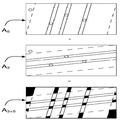
도 1a는 터치 감지 장치의 측면도이고, 도 1b는 터치 감지 장치의 팬빔 실시형태의 상부 평면도이고, 도 1c는 터치 감지 장치의 스캔빔 실시형태의 상부 평면도이고, 도 1d는 스캔빔 실시형태의 투사 신호의 생성을 도시한다.
도 2는 일 실시형태에 따른 터치 결정 방법의 순서도이다.
도 3a 및 도 3b는 터치 시그너처를 가진 투사 신호의 도표이다.
도 4a는 광선 및 터치 객체 간의 상호작용을 포함하는 스캔빔 실시형태를 도시하고, 도 4b는 특정의 빔 스위핑에 대한 비조명 구역을 도시한다.
도 5a 및 도 5b는 2개의 상이한 투사 신호에 대한 감쇠 경로 및 비조명 구역을 도시한다.
도 6a 내지 도 6c는 도 4a의 스캔빔 실시형태에 대해 획득된 다각형 세트, 다각형 교차점, 분석 영역을 도시한다.
도 7은 도 6의 다각형 세트, 및 다각형 세트의 상이한 조합 순서에 의해 획득된 다각형 교차점 및 분석 영역을 도시한다.
도 8a는 광선 및 터치 객체 간의 상호작용을 포함하는 팬빔 실시형태를 도시하고, 도 8b는 대응하는 다각형 세트를 도시한다.
도 9는 도 8b의 다각형 세트를 조합함으로써 획득된 다각형 교차점 및 분석 영역을 도시한다.
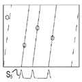
도 10a 내지 도 10g는 분석 영역을 식별하는 중심선 기법을 도시한다.
도 11a는 전체 재구성에 의해 발생된 감쇠값의 도표를 도시하고, 도 11b는 다각형 교차점에 의해 식별된 분석 영역의 도표이고, 도 11c는 국부 재구성에 의해 발생된 감쇠값의 도표이다.
도 12a 및 도 12b는 터치 위치를 결정하는 예시적인 방법의 순서도이다.
도 13a 및 도 13b는 터치 위치를 결정하는 장치의 블록도이다.
도 14a 내지 도 14c는 하나의 터치 객체를 가진 상황에 대해, 투사 신호, 백그라운드 신호, 전송 신호를 아웃커플링 부위 내의 위치의 함수로 각각 도시하는 도표이다.
도 15a 및 도 15b는 터치 감지 장치 내의 산란에 의해 야기된 분산 함수의 그래프이다.
도 16a 내지 도 16d는 도 15a 및 도 15b의 분산 함수의 근원을 도시하기 위한 투광성 패널 내부에 진행되는 빔의 상부 평면도이다.
도 17a 및 도 17b는 감쇠 경로의 생성을 도시하기 위한 스캔빔 실시형태의 상부 평면도이다.
도 18a 및 도 18b는 감쇠 경로의 생성을 도시하기 위한 팬빔 실시형태의 상부 평면도이다.
도 19는 측정 데이터에 기반하는 분산 함수의 그래프이다.In the following, embodiments of the present invention will be described in more detail with reference to the accompanying schematic drawings.
1A is a side view of a touch sensing device, FIG. 1B is a top plan view of a fan beam embodiment of the touch sensing device, FIG. 1C is a top plan view of a scan beam embodiment of the touch sensing device, and FIG. 1D is a projection of a scan beam embodiment The generation of the signal is shown.
2 is a flowchart of a touch determination method according to an embodiment.
3A and 3B are diagrams of projection signals with touch signatures.
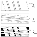
FIG. 4A illustrates a scanbeam embodiment that includes interaction between light rays and touch objects, and FIG. 4B illustrates non-illumination zones for certain beam sweeping.
5A and 5B show attenuation paths and non-illumination zones for two different projection signals.
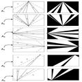
6A-6C illustrate polygon sets, polygon intersections, and analysis regions obtained for the scanbeam embodiment of FIG. 4A.
FIG. 7 shows polygon intersections and analysis regions obtained by the polygon set of FIG. 6 and the different combination order of the polygon sets.
FIG. 8A illustrates a fanbeam embodiment that includes interaction between light rays and touch objects, and FIG. 8B illustrates a corresponding polygonal set.
9 shows polygon intersections and analysis regions obtained by combining the polygon sets of FIG. 8B.
10A-10G illustrate a centerline technique for identifying analysis regions.
FIG. 11A shows a plot of the attenuation values generated by the overall reconstruction, FIG. 11B is a plot of the analysis region identified by the polygon intersections, and FIG. 11C is a plot of the attenuation values generated by the local reconstructions.
12A and 12B are flowcharts of an example method of determining touch location.
13A and 13B are block diagrams of an apparatus for determining touch positions.
14A to 14C are diagrams respectively showing projection signals, background signals, and transmission signals as a function of position in the outcoupling portion, for a situation with one touch object.
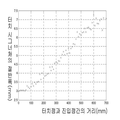
15A and 15B are graphs of the dispersion function caused by scattering in the touch sensitive device.
16A-16D are top plan views of beams traveling inside the translucent panel to illustrate the source of the dispersion function of FIGS. 15A and 15B.
17A and 17B are top plan views of a scanbeam embodiment to illustrate generation of attenuation paths.
18A and 18B are top plan views of a fanbeam embodiment to illustrate generation of attenuation paths.
19 is a graph of a variance function based on measurement data.
본 발명은 터치 감지 장치의 터치면 상의 하나 이상의 객체, 통상 다수의 객체의 위치를 검출하는 기법에 관한 것이다. 투광성 패널의 내부를 조명하는 다수의 예시적인 광원부와 관련하여 터치 결정을 위한 전반사장애(FTIR)의 사용을 제시함으로써 설명을 시작한다. 이후, 터치 결정 방법을 설명하고, 상기 방법의 소정의 단계들을 보다 상세히 설명한다. 마지막으로, 투광성 패널 내의 산란에 의해 야기된 신호 분산의 영향을 설명하고, 신호 분산을 이용하여 터치 결정 방법을 개선하는 방법을 설명한다.The present invention relates to a technique for detecting the position of one or more objects, typically a plurality of objects, on a touch surface of a touch sensitive device. The description begins by suggesting the use of Total Reflectance Disturbance (FTIR) for touch determination in connection with a number of exemplary light sources that illuminate the interior of the translucent panel. Hereinafter, the touch determination method will be described, and certain steps of the method will be described in more detail. Finally, the influence of signal dispersion caused by scattering in the translucent panel will be described, and a method of improving the touch decision method using signal dispersion will be described.
전체 설명에 걸쳐, 대응하는 구성요소를 식별하기 위해 동일한 참조번호가 사용된다.Throughout the description, the same reference numbers are used to identify corresponding components.
소정의 신호, 신호 파라미터, 신호 표현을 식별하기 위해 하기 기호들이 사용된다.The following symbols are used to identify a given signal, signal parameter, signal representation.
Si: 공간 전송 신호(i)S i : spatial transmission signal (i)
Pi ,j: 공간 전송 신호(i)의 피크(j)P i , j : Peak j of spatial transmission signal i
bi ,j,l: 공간 전송 신호(i)의 피크(j)의 좌측 한계b i , j, l : left limit of peak j of spatial transmission signal i
bi ,j,r: 공간 전송 신호(i)의 피크(j)의 우측 한계b i , j, r : right limit of peak j of spatial transmission signal i
bi ,j,m: 공간 전송 신호(i)의 피크(j)의 국부 최소값 위치b i , j, m : local minimum value position of peak j of spatial transmission signal i
Ai: 공간 전송 신호(i)를 위한 다각형 세트A i : Polygon set for spatial transmission signal (i)
Ai ,j: 다각형 세트(i)의 감쇠 경로(j)A i , j : Attenuation path (j) of polygon set (i)
Di ,j: 다각형 세트(i)의 데드존(j)D i , j : Dead zone (j) of polygon set (i)
Ai +k: 다각형 세트들(Ai, Ak)의 교차점A i + k : Intersection of polygon sets (A i , A k )
조명 및 검출Illumination and detection
도 1a는 터치 감지 장치의 예시적인 배치의 측면도이다. 상기 배치는, 투광성 패널(1), 하나 이상의 광이미터(2; 하나만 도시), 및 하나 이상의 광센서(3; 하나만 도시)를 포함한다. 패널에는 서로 대향하고 대략 평행한 2개의 면(4, 5)이 정의되고, 이러한 패널은 평면형이거나 만곡형일 수 있다. 복사 진행 채널이 패널의 두 경계면 사이에 제공되고, 경계면(4, 5) 중 적어도 하나는 진행되는 광이 터치 객체(6)와 상호작용할 수 있게 한다. 통상, 이미터(들)(2)의 광은 복사 진행 채널에서 전반사(TIR)에 의해 진행되고, 센서(3)들은 패널(1)의 주변부에 배치되어, 수신된 광의 에너지를 나타내는 각각의 출력 신호를 생성한다.1A is a side view of an exemplary arrangement of a touch sensitive device. The arrangement comprises a
도 1a에 도시된 바와 같이, 광은 패널(1)의 상하면(4, 5)을 연결하는 가장자리를 통해 패널(1)의 내외부로 직접 커플링될 수 있다. 대안으로, 패널(1)의 내부 및/또는 외부로 광을 커플링하기 위해, 별개의 커플링 요소(미도시; 예컨대, 웨지 형태)가 패널(1)의 상면(4)이나 하면(5) 또는 가장자리에 부착될 수 있다. 객체(6)가 상면(4)에 충분히 가까운 경우, 광의 일부는 객체(6)에 의해 산란될 수 있고, 다른 일부는 객체(6)에 의해 흡수될 수 있으며, 또 다른 일부는 영향 받지 않으며 계속 진행될 수 있다. 따라서, 객체(6)가 도 1a에서 패널의 상면(4)을 터치하는 경우, 전반사 장애가 있고, 전달되는 광의 에너지가 감소한다.As shown in FIG. 1A, light can be coupled directly into and out of the
복수의 상이한 방향으로부터 패널(1)을 통해 전달되는 광의 에너지를 측정함으로써 터치 객체(6)의 위치를 결정하기도 한다. 이는 예컨대 다수의 이격된 이미터(2)들을 작동하여 패널(1) 내측에 대응하는 개수의 광시트를 형성하고 센서(3)들을 작동하여 각각의 광시트의 전달되는 에너지를 검출함으로써 이행될 수 있다. 터치 객체가 2개 이상의 광시트를 감쇠하는 한, 객체의 위치가 결정될 수 있다. 도 1a의 실시형태에서는, 터치 객체(6)의 위치를 결정하기 위해 센서(들)(3)의 출력 신호(들)을 처리하는 데이터 처리 장치(7)가 구성된다.The position of the
도 1a에 도시된 바와 같이, 광은 터치 객체(6)에 의해 차단되지 않을 것이다. 그러므로, 두 객체가 이미터(2)와 센서(3) 간의 광경로를 따라 잇따라 배치되는 경우, 광의 일부는 두 객체와 상호작용할 것이다. 광에너지가 충분하다면, 나머지 광은 센서(3)에 도달하여, 두 번의 상호작용(터치점)이 식별될 수 있도록 출력 신호를 생성할 것이다. 일반적으로, 각각의 터치점은 0 내지 1 범위, 통상 0.7 내지 0.99 범위의 전달률(transmission)을 가진다. 광경로(i)를 따른 전체 전달률(ti)은 광경로 상의 터치점들의 개별 전달률(tn)들의 곱(![]()
![]()
도 1b 및 도 1c는 투광성 패널(1) 내측에 광시트를 생성하는 예시적인 광원부, 및 각각의 시트의 전달되는 에너지를 검출하는 광센서부를 도시한다.1B and 1C show an exemplary light source portion for generating a light sheet inside the
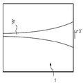
도 1b의 실시형태에서, 2개의 이격된 이미터(2)의 광이 패널(1) 내부로 커플링되어 전반사에 의해 패널(1) 내부에서 진행된다. 각각의 이미터(2)는 광빔(B1, B2)을 생성하되, 이들은 패널(1)의 평면에서 확장되는 한편 이미터(2)로부터 멀리 진행된다. 이러한 빔은 팬빔으로 지칭되고, 이러한 유형의 실시형태는 후술하는 내용에서 일반적으로 "팬빔 실시형태"로 지칭된다. 각각의 팬빔(B1, B2)은 패널(1) 상의 인커플링 부위 내의 하나 이상의 진입점 또는 인커플링점으로부터 진행되어 광시트를 형성하고, 이 예에서 상기 광시트는 본질적으로 전체 패널(1)을 통해 분포된다. 광센서(3) 어레이가 패널(1)의 주변부 주위에 위치되어, 패널(1) 상의 아웃커플링 부위 내의 다수의 이격된 아웃커플링점에서 이미터(2)로부터 광을 수신한다. 객체의 위치는 광센서(3) 어레이에서 각각의 이미터(2)의 광의 감쇠에 기반하여 삼각측량법에 의해 결정될 수 있다. 이러한 유형의 터치 감지 장치는 예컨대 전술한 US2004/0252091호에 주지되어 있고, 이에 참조로서 통합된다.In the embodiment of FIG. 1B, the light of two spaced
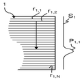
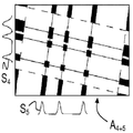
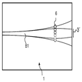
도 1c의 실시형태에서, 두 빔(B1, B2)은 2개의 상이한 방향(R1, R2)으로 패널을 가로질러 스위핑되고, 각각의 전달되는 빔의 에너지가 스위핑 동안 측정된다. 통상적으로, 각각의 빔(B1, B2)은 패널(1)의 평면에서 시준된다(collimated). 이러한 유형의 실시형태는 후술하는 내용에서 일반적으로 "스캔빔 실시형태"로 지칭된다. 시준된 빔(B1, B2)의 스위핑에 의해 광시트가 형성된다. 구체적으로, 각각의 빔(B1, B2)은 생성된 후, 입력 스캐너부(8)에 의해 패널(1) 상의 인커플링 부위 내의 진입점 또는 인커플링점 세트를 따라 스위핑된다. 도시된 예에서, 진입점들은 패널(1)의 좌측 및 상부 가장자리에 위치한다. 패널(1) 상의 아웃커플링 부위 내의 다수의 아웃커플링점에서의 전달 에너지는, 빔(B1, B2)이 패널(1)을 가로질러 스위핑될 때 빔(B1, B2)을 수신하기 위해 입력 스캐너부(8)와 동기되는 출력 스캐너부(9)에 의해 측정된다. 도시된 예에서, 아웃커플링점들은 진입점들과 반대편에, 패널(1)의 우측 및 하부 가장자리에 위치한다.In the embodiment of FIG. 1C, the two beams B1, B2 are swept across the panel in two different directions R1, R2, and the energy of each transmitted beam is measured during the sweep. Typically, each beam B1, B2 is collimated in the plane of the
각각의 출력 스캐너부(9)는 통상 빔 스캐너 및 하나의 광센서(미도시)를 포함한다. 마찬가지로, 각각의 입력 스캐너부(8)는 통상 이미터 및 빔 스캐너(미도시)를 포함한다. 그러나, 2개 이상의 입력 스캐너부가 하나의 동일한 광이미터를 공유하고/하거나, 2개 이상의 출력 스캐너부가 하나의 동일한 광센서를 공유하는 것도 고려할 수 있다. 또한, 3개 이상의 빔이 패널을 가로질러 스위핑될 수 있음은 물론이다. 통상적으로, 빔은 패널을 가로질러 병진운동한다. 다시 말하면, 빔은 패널의 평면에서 본질적으로 불변각(스캔각)을 가진다. 도 1c에 도시되지 않았지만, 입력 스캐너부(8)의 유입광을 원하는 방향("스캔각")으로 방향 전환하기 위해, 그리고 전달되는 광을 출력 스캐너부(9) 상의 공통 초점 영역/지점을 향해 방향 전환하기 위해, 특정의 광학 부품들이 각각 인커플링 부위 및 아웃커플링 부위와 연관된다. 도 1c의 예에서, 빔(B1, B2)은 본질적으로 패널(1)의 각각의 가장자리와 평행하다. 그러나, 빔(B1, B2)이 패널(1)을 가로질러 스위핑될 때 빔(B1, B2)의 스캔각이 변화되는 것도 고려할 수 있다. 도시된 실시형태 및 대안적인 구성이 본 출원인의 PCT 공개 WO2010/006882호 및 WO2010/006885호에 더 기재되어 있고, 이에 참조로서 통합된다.Each
도 1c의 실시형태의 대안(미도시)으로, 각각의 출력 스캐너부(9) 및 방향전환용 광학 부품은, 패널 가장자리를 따라 연장되며 패널에 광학적으로 연결되는 각각의 기다란 센서로 교체된다. 각각의 기다란 센서는 빔이 패널 상에서 인커플링 부위를 따라 스위핑되는 동안 수신되는 에너지를 시간의 함수로 측정하도록 제어된다. 그러므로, 도 1c의 실시형태와 마찬가지로, 전달되는 에너지가 패널 상의 아웃커플링 부위 내의 다수의 아웃커플링점에서 측정되고, 아웃커플링점들은 기다란 센서의 출력 신호의 상이한 시점들에 대응한다. 변형예에서, 방향전환용 광학 부품은 유지되지만, 각각의 출력 스캐너부(9)는 정적 복사 검출기로 대체되고, 이는 패널 가장자리로부터 이격되어 전술한 공통 초점 영역/지점에 마련된다. 이러한 변형예에서, 정적 복사 검출기는 빔이 패널 상에서 인커플링 부위를 따라 스위핑되는 동안 수신되는 에너지를 시간의 함수로 측정하도록 제어된다. 이러한 대안예와 변형예가 본 출원인의 PCT 공개 WO2010/006884호 및 WO2010/006886호에 더 기재되어 있고, 이에 참조로서 통합된다.As an alternative (not shown) of the embodiment of FIG. 1C, each
도 1c의 실시형태의 다른 대안(미도시)으로, 출력 스캐너부(9)는 생략되고 재귀반사체(retro-reflectors)로 교체되어, 빔(B, B2)이 각각의 입력 스캐너부(8)로 다시 반사된다. 그러므로, 입력 스캐너부(8)는 전달되는 에너지를 측정하기 위해 빔을 스위핑하고 수신하는 송수신기로 구성된다. 이러한 대안예는 본 출원인의 PCT 공개 WO2009/048365호에 더 기재되어 있고, 이에 참조로서 통합된다.In another alternative (not shown) of the embodiment of FIG. 1C, the
전술한 모든 실시형태에서, 센서(들)(3)의 출력 신호는 패널을 가로질러 연장되는 전체 검출선 세트 상의 측정 에너지를 나타내며, 각각의 검출선은 인커플링점과 아웃커플링점의 고유의 쌍 사이로 연장되고, 그에 따라 패널의 평면도에 도시된 바와 같이, 패널 상에서 고유의 방향 및 위치를 가진다. 터치 결정 처리를 거치기 전에, 출력 신호들은 각각의 광시트에 대한 하나의 공간 전송 신호로 모아질 수 있다. 따라서, 공간 전송 신호는 패널의 주변부 주위의 다양한 위치에서의 수신 에너지를 나타낸다. 공간 전송 신호는 다양한 위치에서의 진정한 광전달(또는 균등하게, 감쇠)을 나타내도록 백그라운드 신호에 의해 선택적으로 정규화되었을 수 있고, 이는 이하에 예시된 바와 같다. 후술하는 설명에서, 공간 전송 신호는 "투사(projection)" 또는 "투사 신호(projection signal)"로도 지칭된다.In all the embodiments described above, the output signal of the sensor (s) 3 represents the measured energy on the entire set of detection lines extending across the panel, each detection line being a unique pair of incoupling points and outcoupling points. Extending in between and thus having a unique orientation and position on the panel, as shown in the plan view of the panel. Prior to the touch decision processing, the output signals can be gathered into one spatial transmission signal for each optical sheet. Thus, the spatial transmission signal represents the received energy at various locations around the periphery of the panel. The spatial transmission signal may be selectively normalized by a background signal to indicate true light transmission (or evenly, attenuation) at various locations, as illustrated below. In the following description, the spatial transmission signal is also referred to as "projection" or "projection signal".
본원에 기재된 바와 같이, 팬빔 실시형태에서는, 각각의 이미터에 대해 하나의 공간 전송 신호가 획득되고, 상기 공간 전송 신호는, 시스템의 모든 아웃커플링점에서 측정되며 특정의 이미터로부터 기인하는 에너지값의 집합(ensemble)에 기반한다. 본원에 기재된 바와 같이, 스캔빔 실시형태에서는, 각각의 빔 스위핑에 대해 하나의 공간 전송 신호가 획득되고, 상기 공간 전송 신호는, 특정의 빔이 시스템의 아웃커플링점들(통상 단일 아웃커플링 부위 내)을 따라 스위핑되는 동안 측정되는 에너지값의 집합에 기반한다.As described herein, in a fanbeam embodiment, one spatial transmission signal is obtained for each emitter, the spatial transmission signal being measured at all outcoupling points of the system and resulting from a particular emitter Based on an ensemble of As described herein, in a scanbeam embodiment, one spatial transmission signal is obtained for each beam sweep, wherein the spatial transmission signal is determined such that a particular beam is coupled to the system's outcoupling points (usually a single outcoupling site). Based on the set of energy values measured during sweep along
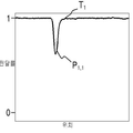
이러한 양상을 더 예시하기 위해, 도 1d는 도 1c의 우측단 출력 스캐너부(9) 또는 전술한 대안들 중 어느 하나에서 획득된 공간 전송 신호(S1)를 도시한다. 도 1d는 또한 광빔(B1)이 패널(1)을 가로질러 스위핑되는 동안 광빔(B1)에 대한 대응하는 검출선 세트(r1 ,1,...,r1 ,N)를 개략적으로 도시하되, 검출선들의 밀도는 임의적이며 부재 시에는 출력 스캐너부(9)의 샘플링 속도에 따라 좌우된다. 공간 전송 신호(S1)는 예컨대 패널(1)의 우측단 가장자리를 따르는 위치에 상응하는 시간의 함수로 주어질 수 있다. 전송 신호(S1)는 터치 객체(미도시)로부터 발생된 신호 프로파일(P1 ,1)을 포함하는 것으로 도시된다. 일반적으로, 이러한 신호 프로파일(P1 ,1)은 후술하는 내용에서 "터치 시그너처"로도 지칭된다.To further illustrate this aspect, FIG. 1D shows the spatial transmission signal S 1 obtained in the right end
터치 결정Touch decision
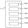
도 2는 도 1과 관련하여 설명되고 논의된 바와 같은 터치 감지 장치에서 획득된 출력 신호에 기반하는 예시적인 터치 결정 방법의 흐름도이다. 방법의 개요를 제공하고 개별 단계 및/또는 그 조합의 소정의 이점을 제공하기 위해, 상기 방법의 단계들이 이하에 간략하게 설명될 것이다.FIG. 2 is a flow diagram of an exemplary touch determination method based on an output signal obtained in a touch sensing device as described and discussed with respect to FIG. 1. In order to provide an overview of the method and to provide certain advantages of the individual steps and / or combinations thereof, the steps of the method will be briefly described below.
상기 방법은 반복적이며, 각각의 단계들(201~208)의 반복은 "감지 인스턴스(sensing instance)"로 지칭된다. 그러므로, 단계(201)에서, 감지 인스턴스는, 이미터가 활성화된 동안, 센서의 출력 신호, 통상 각각의 검출선에 대한 하나의 에너지값의 샘플링을 가능하게 함으로써 시작된다. 구현예에 따라, 이미터들은 (적어도 부분적으로) 동시에 또는 순차적으로 활성화될 수 있다.The method is iterative and the repetition of each of the steps 201-208 is referred to as a "sensing instance". Therefore, in
이후, 단계(202)에서는, 전술한 바와 같이, 출력 신호에 기반하여 공간 전송 신호를 생성한다.Then, in
단계(203)에서, 피크, 즉 잠재적인 터치 시그너처의 식별을 위해 공간 전송 신호를 처리한다. 처리 결과는 각각의 피크에 대한 한계점 쌍이고, 상기 한계점들은 공간 전송 신호의 피크의 범위 및 위치를 나타낸다. 공간 전송 신호가 아웃커플링점과 상호 관련되므로, 한계점 쌍 역시 터치면의 주변부를 따라 아웃커플링점 쌍에 매핑된다.In
단계(204)에서, 식별된 한계점에 기반하여 각각의 공간 전송 신호에 대해 다각형 세트를 생성한다. 공간 전송 신호의 식별된 피크로 판단할 때, 다각형 세트는 하나 이상의 터치 객체가 위치될 수 있는 터치면을 가로지른 경로를 나타낸다. 다각형 세트는 터치 패널을 가로지른 모든 검출선의 방향 및 패널의 기하학적 레이아웃과 같은 주지의 시스템 파라미터를 이용하여 생성된다. 기본적으로, 다각형 세트는 터치면을 가로질러 연관 검출선을 따라 아웃커플링점으로부터 각각의 한계점을 재추적함으로써 생성되어, 각각의 피크에 대한 감쇠 경로를 정의한다. 아울러, 하나 이상의 다각형이 각각의 공간 전송 신호의 "데드존(dead zone)", 즉 관련 아웃커플링 부위에 도달하는 광에 의해 조명되지 않는 터치면 상의 모든 구역을 차지하도록 감쇠 경로(들)에 추가될 수 있다. 따라서, 데드존의 터치 객체는 공간 전송 신호에서 터치 시그너처로 나타나지 않을 것이다.In
다음으로, 단계(205)에서, 통상 논리곱 연산에 의해 다각형 세트를 조합함으로써 분석 영역을 식별한다. 그에 따라, 단계(202)에서 생성된 공간 전송 신호의 집합에 포함된 정보를 고려할 때, 분석 영역은 하나 이상의 터치 객체가 위치했을 수 있는 터치면 상의 영역이다.Next, in
단계(206)에서, 단지 분석 영역 내의 공간 전송 신호에만 기반하여 공간 분포도(spatial distribution map)를 재구성한다("국부 재구성"으로 지칭된다). 공간 분포도는 터치면을 가로지른 에너지관련 파라미터(예컨대, 에너지, 감쇠, 또는 전달)의 공간 분포를 나타낸다. 일반적으로 말해서, 공간 분포도의 재구성은 통상 역투사 알고리즘, 중복결정 수식 시스템, 또는 공간 전송 신호에 적용되는 통계적 모델, 또는 이들의 도함수 중 하나 이상을 수반하는 처리집약적 연산이다. 재구성을 분석 영역에만 제한함으로써, 재구성을 위한 계산 시간 및/또는 필요 처리 전력이 상당히 감소할 수 있다. 또한, 국부 재구성 과정은 전체 재구성보다 더 많이 중복결정될 수 있기 때문에, 재구성 과정의 계산 안정성을 증가시킬 수 있다.In
단계(206)에 미치는 단계(205)의 영향을 더 설명하기 위해 와이드스크린(16:9) 포맷의 40인치 터치 패널을 고려한다. 이러한 터치 플레이트의 총면적은 약 4400㎠이다. 각각 1㎠의 면적을 가지는 10개의 객체가 패널을 터치한다고 가정한다. 도 1c의 배치에서, 두 빔이 패널을 가로질러 직교 스캔되는 경우, 분석 영역의 최대수는 100이고 총분석 면적의 최대값은 약 100㎠일 것이다. 그러므로, 재구성 과정에서 분석 영역만을 고려함으로써 재구성 면적이 44배 감소한다.To further illustrate the effect of
재구성 후, 단계(207)에서, 모든 진정한 터치점의 식별을 위해 공간 분포도를 분석한다. 다음으로, 단계(208)에서는 식별된 터치점에 대해 터치 데이터를 추출 및 출력하고, 상기 과정은 새로운 반복을 위해 단계(201)로 되돌아간다. 터치점의 XY 좌표, 면적, 형상, 및/또는 압력을 포함하지만 이에 제한되지 않는 모든 유효 터치 데이터가 추출될 수 있다.After reconstruction, in
이하에서는, 단계들(203~207)의 실시형태가 보다 상세히 설명될 것이다. 후술하는 설명에서, 공간 전송 신호는 0 내지 1의 범위에 속하도록 정규화된 전달 광의 감쇠를 나타내는 것으로 가정된다. 그러나, 전술한 에너지값 또는 정규화된 에너지값과 같은 공간 전송 신호의 다른 포맷에도 다양한 단계들을 적용할 수 있음은 물론이다.In the following, embodiments of steps 203-207 will be described in more detail. In the description below, it is assumed that the spatial transmission signal exhibits attenuation of the transmitted light normalized to fall in the range of 0-1. However, it goes without saying that various steps may be applied to other formats of the spatial transmission signal, such as the above-described energy value or normalized energy value.
피크 검출 및 분석(203 단계)Peak Detection and Analysis (Step 203)
일 실시형태에서, 공간 전송 신호는 명시된 임계값 이상의 감쇠를 가진 모든 피크를 검출하기 위해 처리된다. 임계값은 임의의 적절한 값으로 고정 설정될 수 있지만, 일반적으로 0.25 미만이다. 이 예에서, 임계값은 최약 터치 시그너처를 검출할 수 있도록 약 0.01 내지 0.001의 매우 낮은 값으로 설정된다. 일반적으로, 임계값은 공간 전송 신호의 노이즈 레벨보다 높게 설정된다. 그에 따라, 피크 검출 단계의 감도를 개선하기 위해서는, 저역통과 필터, 미디언 필터, 푸리에 필터 등과 같은 임의의 표준 필터링 기법을 이용하여, 피크 검출 단계 전에 노이즈 감소를 위해 공간 전송 신호를 사전처리하는 것이 바람직할 수 있다.In one embodiment, the spatial transmission signal is processed to detect all peaks with attenuation above a specified threshold. The threshold can be fixedly set to any suitable value, but is generally less than 0.25. In this example, the threshold is set to a very low value of about 0.01 to 0.001 so that the weakest touch signature can be detected. In general, the threshold is set higher than the noise level of the spatial transmission signal. Thus, to improve the sensitivity of the peak detection phase, it may be desirable to preprocess the spatial transmission signal for noise reduction prior to the peak detection phase using any standard filtering technique, such as a lowpass filter, a median filter, a Fourier filter, or the like. It may be desirable.
도 3a에 나타낸 바와 같이, 피크 검출 단계는 임계값(qt)보다 강력한 신호(Si)의 감쇠 피크(pi ,j)의 한계점(bi ,j,l, bi ,j,r)을 찾아낸다. 후속 재구성 및 식별 단계들(206~207)의 구현예에 따라, 피크 검출 단계는 또한 피크(pi ,j)의 중심점(ci ,j), 폭(wi ,j), 총(적분)감쇠(도 3a의 음영 영역)를 계산할 수 있다. 중심점(ci ,j)은 예컨대 피크의 최대값 또는 한계점(bi ,j,l, bi ,j,r) 간의 중간점으로 식별될 수 있다.As shown in Figure 3a, the peak detecting step is the threshold value (q t) a more robust signal (S i) limit (b i, j, l, b i, j, r) of attenuation peaks (p i, j) of Find it. According to the implementation of the subsequent reconstruction and identification steps 206-207, the peak detection step is also the center point c i , j of the peak p i , j , width w i , j , total (integral) The attenuation (shaded area in FIG. 3A) can be calculated. The center point c i , j can be identified, for example, as the midpoint between the maximum value of the peak or the threshold points b i , j, l , b i , j, r .
피크 검출 단계의 정확도를 개선하기 위해, 임의의 적절한 보간 알고리즘을 이용한 보간에 의해 공간 전송 신호의 신호값들의 밀도를 증가시킬 수 있다. 이는 공간 전송 신호와 연관된 검출선들 및 아웃커플링점들의 공간적 밀도의 증가에 상응한다.In order to improve the accuracy of the peak detection step, the density of the signal values of the spatial transmission signal can be increased by interpolation using any suitable interpolation algorithm. This corresponds to an increase in the spatial density of the detection lines and outcoupling points associated with the spatial transmission signal.
피크 검출 단계의 정확도를 늘리는 다른 방법은, 각각의 피크에 기저 함수 또는 기저 함수 세트를 삽입하고, 삽입된 기저 함수(들) 상에서 한계점을 결정하는 것이다. 기저 함수(들)은 가우시안 벨(Gaussian bell), 코시-로렌츠 분포(Cauchy-Lorentz Distribution), 저역통과필터 톱햇 함수(top-hat function) 등과 같은 임의의 형상을 취할 수 있다.Another way to increase the accuracy of the peak detection step is to insert a basis function or set of basis functions at each peak and determine the threshold on the inserted basis function (s). The basis function (s) can take any shape such as a Gaussian bell, Cauchy-Lorentz Distribution, low pass filter top-hat function, and the like.
피크 검출 단계는 또한, 도 3b에 도시된 바와 같이, 다양한 터치 객체로부터 발생된 중복 피크들(Pi ,j,a, Pi ,j,b)에 의해 형성된 터치 시그너처(Pi,j)를 식별하고 중복 피크들(Pi ,j,a, Pi ,j,b)을 분리하도록 적합화될 수 있다. 조합된 피크(Pi ,j)에 기저 함수 세트(도 3b의 점선으로 나타냄)를 삽입하고, 삽입된 기저 함수에 기반하여 각각의 피크의 한계점을 결정함으로써, 이러한 분리를 달성할 수 있다.The peak detection step also detects the touch signature P i, j formed by overlapping peaks P i , j, a , P i , j, b generated from various touch objects, as shown in FIG. 3B. It can be adapted to identify and separate duplicate peaks (P i , j, a , P i , j, b ). This separation can be achieved by inserting a set of basis functions (indicated by the dashed lines in FIG. 3B) in the combined peaks P i , j and determining the threshold of each peak based on the inserted basis function.
예시적인 피크 검출 단계에서, 각각의 공간 전송 신호는 다음과 같이 처리된다:In an exemplary peak detection step, each spatial transmission signal is processed as follows:
1. 공간 전송 신호의 최좌측단에서 시작된다.1. Start at the leftmost end of the spatial transmission signal.
2. 좌측에서 우측으로 이동하며 공간 전송 신호(Si)의 신호값에 대해 반복하고, 감쇠가 임계값(qt)보다 커지는 위치 및 다시 임계값(qt)보다 작아지는 위치를 찾아낸다. 이러한 위치를 피크(Pi ,j)의 한계점(bi ,j,l, bi ,j,r)으로 저장한다. 각각의 피크(Pi,j)에 대해, 피크가 경계형인지(bounded) 비경계형인지(unbounded), 즉 한계점 중 하나가 공간 전송 신호(Si)의 활성 영역(이하 참조)의 단부와 일치하는지에 관한 정보를 저장한다.2. find the location moves from the left to the right and repeats for the signal value of the spatial transmission signals (S i), and the attenuation is smaller than the threshold value (q t) is larger than the position and the threshold value (q t). This position is stored as the threshold (b i , j, l , b i , j, r ) of the peak P i , j . For each peak (P i, j), a peak boundary type or (bounded) non-border type or (unbounded), i.e., the active region of one of the limit spatial transmission signals (S i) (see below), the ends of the Stores information about the match.
3. 각각의 피크(Pi ,j)에 대해, 잠재적으로 한계점(bi ,j,l, bi ,j,r)이 피크(Pi ,j)로부터 약간 멀리 이동되도록 한계점(bi ,j,l, bi ,j,r)을 처리한다. 예컨대, 각각의 한계점은 신호값의 크기가 감소하는 한 피크로부터 멀리 이동될 수 있다. 이러한 단계는, 임계값(qt)을 넘어서는 신호값을 가진 터치 시그너처의 슬림 영역만이 아니라, 약한 터치 시그너처의 전체가 포함되도록 보장할 수 있다. 다음으로, 결과적인 한계점은 후속 계산에서 한계점으로 사용된다.3. The threshold (b i to be slightly moved away from for each peak (P i, j), a potentially critical point (b i, j, l, b i, j, r) , the peak (P i, j), j, l , b i , j, r ) For example, each threshold can be moved away from the peak as long as the magnitude of the signal value decreases. This step can ensure that not only the slim region of the touch signature with the signal value above the threshold q t is included but also the entire weak touch signature. The resulting limit is then used as the limit in subsequent calculations.
4. 모든 피크(Pi ,j)에 대해, 임의의 적절한 알고리즘을 이용하여 한계점들 간의 국부 최소값을 검색하되, 국부 최소값의 깊이가 기결정 또는 기설정된 노이즈 임계값을 초과해야 한다는 추가 제약이 존재할 수 있다. 각각의 피크에 대한 국부 최소값(bi,j,m)에 관한 정보를 저장한다.4. For every peak (P i , j ), there is an additional constraint that any suitable algorithm is used to retrieve the local minimum between the thresholds, but the depth of the local minimum must exceed a predetermined or predetermined noise threshold. Can be. Store information about the local minimum (b i, j, m ) for each peak.
5. 하나 이상의 국부 최소값을 가진 모든 피크에 대해, 피크를 분할한다. 분할된 피크의 한계점은, 국부 최소값의 위치를 한계점으로 이용하거나 임의의 다른 적절한 기법에 의해 앞서 언급된 기저 함수를 이용하여 결정될 수 있다.5. For all peaks with one or more local minimums, divide the peaks. The threshold of the divided peak can be determined using the location of the local minimum as the threshold or using the basis function mentioned above by any other suitable technique.
다각형 세트의 생성(204 단계)Creating a Polygon Set (Step 204)
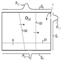
다각형 세트를 생성하는 단계의 설명 및 예시를 위해 도 4a의 스캔빔 실시형태를 고려한다. 여기서, 6개의 빔(B1~B6)이 터치면을 가로질러 스위핑되는데, 제1 빔 세트(B1, B3, B4)는 제1 인커플링 부위(10)로부터 제1 아웃커플링 부위(11)로 진행되도록 주사되는 한편 제1 주요 방향(R1)으로 스위핑되고, 제2 빔 세트(B2, B5, B6)는 제2 인커플링 부위(10)로부터 제2 아웃커플링 부위(11)로 진행되도록 주사되는 한편 제2 주요 방향(R2)으로 스위핑된다. 제1 및 제2 주요 방향(R1, R2)은 서로 직교하며 패널의 가장자리와 평행하다. 제1 빔 세트는 제1 인커플링 부위(10)에 수직인 하나의 빔(B1), 및 2개의 비수직 비평행 빔(B3, B4)을 포함한다. 제2 빔 세트는 제2 인커플링 부위(10)에 수직인 하나의 빔(B2), 및 2개의 비수직 비평행 빔(B5, B6)을 포함한다.Consider the scanbeam embodiment of FIG. 4A for description and illustration of generating a polygon set. Here, six beams B1 to B6 are swept across the touch surface, and the first beam set B1, B3, B4 is connected to the
도 4a는 각각의 빔의 중심 광선이 터치면 상의 4개의 터치 객체(6)의 외부 경계와 상호작용하는 방법을 도시한다.4a shows how the central ray of each beam interacts with the outer boundaries of four
도 4b는 빔(B5)에 대해 조명된 구역을 도시한다. 빔(B5)은 제1 인커플링 부위에 수직이 아니므로, 단지 터치 패널의 서브세트를 가로질러서만 스위핑될 것이고, 소정의 부분("데드 존")이 조명 없이 남겨진다(또는 본질적으로 조명이 없다). 화살표(IN5)는 빔(B5)에 의해 스위핑되는 제1 인커플링 부위의 범위를 도시하는 반면, 화살표(OUT5)는 빔(B5)에 의해 스위핑되는 제1 아웃커플링 부위의 범위를 도시한다. 화살표(OUT5)는 또한 빔(B5)이 제1 아웃커플링 부위에 매핑될 때 빔(B5)에 대한 공간 전송 신호의 활성 영역을 나타낸다.4b shows the illuminated area for the beam B5. Since the beam B5 is not perpendicular to the first incoupling site, it will only be swept across a subset of the touch panel, and certain portions (“dead zones”) are left without illumination (or essentially illumination). There is no). Arrow IN5 shows the range of the first incoupling site swept by beam B5, while arrow OUT5 shows the range of the first outcoupling site swept by beam B5. . Arrow OUT5 also indicates the active area of the spatial transmission signal for beam B5 when beam B5 is mapped to the first outcoupling site.
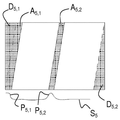
도 5a는 터치 패널의 평면도, 및 빔(B5)에 대해 획득된 공간 전송 신호(S5)의 예를 보여준다. 아울러, 신호(S5)의 피크(P5 ,1, P5 ,2)에 대응하는 감쇠 경로(A5,1, A5,2)가 음영 영역으로 표시된다. 마찬가지로, 신호(S5)와 연관된 데드존(D5,1, D5,2)이 음영 영역으로 표시된다.5A shows a top view of the touch panel, and an example of the spatial transmission signal S 5 obtained for the beam B5. In addition, the attenuation path (A 5,1, A 5,2) corresponding to the peak (P 5, 1, P 5 , 2) of the signal (S 5) is represented by the shaded area. Similarly, dead zones D 5,1 , D 5,2 associated with signal S 5 are represented by shaded areas.
도 5b는 빔(B5)에 대해 획득된 피크(P5 ,1, P5 ,2)를 가진 공간 전송 신호(S5)의 다른 예, 및 대응하는 감쇠 경로(A5,1, A5,2)와 데드존(D5 ,1, D5 ,2)을 보여준다. 피크(P5 ,1)는 비경계형이고, 감쇠 경로(A5,1)는 적어도 부분적으로 데드존(D5,1)과 중첩됨을 주목할 수 있다.Figure 5b shows another example of the spatial transmission signal (S 5) having a peak (P 5, 1, P 5 , 2) obtained for the beam (B5), and a corresponding attenuation of the path (A 5,1, A 5, 2 ) and the dead zone (D 5 , 1 , D 5 , 2 ). Peak (P 5, 1) may be noted that the non-boundary type and the path attenuation (A 5,1) are at least partially overlapped with the dead zone (D 5,1).
다각형 세트를 생성하는 단계는, 공간 전송 신호에 기반하여, 터치 객체가 위치했을 수 있는 터치 패널 상의 모든 영역을 나타내는 다각형을 생성하는 단계를 수반한다. 공간 전송 신호가 데드존에 관한 정보를 포함하지 않기 때문에, 데드존은 다각형 세트에 포함된다.Generating a polygon set involves generating a polygon representing all areas on the touch panel on which the touch object may have been located, based on the spatial transmission signal. Since the spatial transmission signal does not contain information about the dead zone, the dead zone is included in the polygon set.
따라서, 도 5a 및 도 5b의 음영 영역(A5,1, A5,2, D5 ,1, D5 ,2)은 또한 각각의 신호(S5)에 대한 다각형 세트를 나타낸다. 도 5b의 비경계형 피크(P5 ,1)의 데드존(D5 ,1) 및 감쇠 경로(A5,1)가 별개의 다각형 또는 단일의 조합된 다각형에 의해 나타내질 수 있음을 주목할 수 있다.Thus, Figure 5a, and the shaded area of Figure 5b (A 5,1, A 5,2, D 5, 1,
도 4a의 터치 객체 세트 및 스캔빔 실시형태로 되돌아가면, 빔(B1~B6)에 대해 생성된 결과적인 다각형 세트(A1~A6)가 도 6a 내지 도 6c에 도시되어 있다. 도 6 및 후속 도면에서, 실선은 감쇠 경로의 경계를 나타내고, 파선은 데드존의 한계를 나타낸다.Returning to the touch object set and scanbeam embodiment of FIG. 4A, the resulting polygonal sets A 1 -A 6 generated for beams B1-B6 are shown in FIGS. 6A-6C. In FIG. 6 and subsequent figures, the solid line represents the boundary of the attenuation path and the dashed line represents the limit of the dead zone.
그러므로, 단계(204)의 결과로, 각각의 공간 전송 신호에 대해 하나의 다각형 세트가 생성되고, 다각형 세트(Ai)는 공간 전송 신호(Si)에 대해 생성된 모든 다각형(Ai ,p)의 합집합(union)이다:Therefore, as a result of

분석 영역의 결정(205 단계)Determination of Analysis Area (Step 205)
분석 영역을 결정하는 단계는, 다양한 공간 전송 신호(Si)에 대해 생성된 다각형 세트(Ai)의 총교차점(Atotal)을 추정 또는 계산하는 단계를 수반한다:Determining an analysis region, a total of intersection (A total) of the polygon set (A i) generated for the various spatial transmission signals (S i) involves the step of estimating or calculating:

두 다각형 세트의 교차점은 터치 패널의 좌표 시스템 내의 두 다각형 세트의 다각형들의 쌍단위(pairwise) 매칭에 의해 계산될 수 있다. 당해 기술분야의 숙련자에게 주지된 바와 같이, 교차점의 계산은 논리곱 연산의 수행에 대응한다.The intersection of two polygon sets can be calculated by pairwise matching of polygons of two polygon sets in the coordinate system of the touch panel. As is well known to those skilled in the art, the calculation of the intersection points corresponds to the performance of the AND operation.
다각형들, 특히 볼록 다각형들의 교차점을 계산하기 위한 다수의 효율적인 알고리즘이 종래 기술에 존재한다. 일 예로, Joseph O'Rourke의 "Computational Geometry in C(2nd edition)"의 7.6 챕터에 제시된 선형 시간 알고리즘이 있다. 이 책에는 또한 다각형 교차점에 대한 다양한 검사 및 알고리즘이 기재되어 있다. 대안으로 또는 추가로, 교차점의 계산에는, 예컨대 Christer Ericson의 "Real Time Collision Detection"의 5 챕터(156~160 페이지)에 기재된 바와 같은 분리축 정리(Separating Axis Theorem, SAT)가 이용될 수 있다. 아울러, 예컨대 동일한 책의 6~9 챕터에 기재된 바와 같이, 모든 다각형 쌍을 검사할 필요를 방지하기 위해 기하학적 계층구조를 사용하는 것이 유리할 수 있다.There are many efficient algorithms in the prior art for calculating the intersections of polygons, in particular convex polygons. An example is the linear time algorithm presented in chapter 7.6 of Joseph O'Rourke's "Computational Geometry in C (2nd edition)". The book also describes various checks and algorithms for polygon intersections. Alternatively or additionally, the Separation Axis Theorem (SAT), such as described in Chapter 5 (pages 156-160) of Christer Ericson's "Real Time Collision Detection", can be used to calculate the intersection. In addition, it may be advantageous to use geometric hierarchies to avoid the need to examine all polygon pairs, as described, for example, in chapters 6-9 of the same book.
하나의 다각형이 다른 다각형 내에 완전히 위치되는 경우, 두 다각형의 교차점은 작은쪽 다각형과 동일하게 설정될 것임을 주목해야 한다.Note that if one polygon is located completely within another polygon, the intersection of the two polygons will be set equal to the smaller polygon.
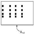
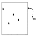
도 6은 다각형 세트들을 교차시키는 과정을 더 도시한다. 전술한 바와 같이, A1~A6은 다양한 공간 전송 신호(S1~S6)에 대해 생성된 다각형 세트를 나타낸다. 도 6a의 예에서, 다각형 세트들(A5, A3)은 교차되어 다각형 교차점(A3+5)을 생성한다. 도면에 걸쳐, 다각형 교차점에 포함된 다각형들은 짙은 부분으로 나타낸다. 도 6b의 예에서, 다각형 세트들(A6, A4)은 교차되어 다각형 교차점(A4+6)을 생성한다. 도 6c의 예에서, 다각형 교차점(A3+5)은 다각형 세트(A2)와 교차되어 다각형 교차점(A2+3+5)을 생성하고, 다각형 교차점(A4+6)은 다각형 세트(A1)와 교차되어 다각형 교차점(A1+4+6)을 생성하고, 다각형 교차점들(A2+3+5, A1+4+6)이 교차되어 최종 교차점(Atotal)을 생성한다. 최종 교차점(Atotal)은 터치 객체가 위치했을 수 있는 분석 영역을 식별한다. 터치면의 총면적에 비해, 터치 객체를 포함했을 수 있는 총면적이 현저히 감소한 것이 분명하다.6 further illustrates the process of intersecting polygon sets. As described above, A 1 to A 6 represent a set of polygons generated for various spatial transmission signals S 1 to S 6 . In the example of FIG. 6A, the polygon sets A 5 , A 3 are crossed to create a polygon intersection A 3 + 5 . Throughout the drawings, the polygons included in the polygon intersections are shown in dark portions. In the example of FIG. 6B, the polygon sets A 6 , A 4 are crossed to create a polygon intersection A 4 + 6 . In the example of FIG. 6C, polygon intersection A 3 + 5 intersects polygon set A 2 to produce polygon intersection A 2 + 3 + 5 , and polygon intersection A 4 + 6 is a polygon set ( is crossed with a 1) generating a polygon intersections (a 1 + 4 + 6) and the polygonal intersection (a 2 + 3 + 5, a 1 + 4 + 6) are crossed to produce the final junction (a total) . The final intersection point (A total ) identifies the analysis area where the touch object may have been located. It is clear that the total area that may have included the touch object is significantly reduced compared to the total area of the touch surface.
이러한 특정의 예에서, 결과적인 분석 영역은 본질적으로 터치 객체와 일치한다는 것(도 4a 참조)을 주목할 수 있고, 그에 따라 재구성 단계(도 2의 206 단계)를 적용함 없이 최종 교차점(Atotal)으로부터 터치점을 직접 식별하는 것이 가능할 수 있다. 그러므로, 특히 패널 내부에 생성된 광시트의 개수와 관련하여 식별될 터치점의 개수가 작을 때 재구성 단계의 생략이 가능할 수 있다.In this particular example, it can be noted that the resulting analysis area essentially coincides with the touch object (see FIG. 4A), and thus the final intersection A total without applying the reconstruction step (step 206 of FIG. 2). It may be possible to identify the touch point directly from. Therefore, it may be possible to omit the reconstruction step especially when the number of touch points to be identified in relation to the number of light sheets generated inside the panel is small.
다각형 세트들이 조합되는(교차되는) 순서가 최종 결과에 중요하진 않음을 알 수 있다. 다양한 다각형 세트로부터 다각형을 조합하는 모든 방법을 사용해도 좋다. 그러나, 각각의 다각형 세트에 대한 검출선들의 기울기에 관한 정보를 활용함으로써 교차 동작의 개수를 감소시킬 수 있다.It can be seen that the order in which the polygon sets are combined (crossed) is not critical to the final result. Any method of combining polygons from different polygon sets may be used. However, the number of crossing motions can be reduced by utilizing information about the slope of the detection lines for each polygon set.
도 4a의 예로 돌아가면, 하나의 동일한 주요 방향(R1, R2)으로 빔 스위핑과 연관된 다각형 세트 그룹을 따로따로 교차시키는 것이 유리할 수 있다. 아울러, 이러한 그룹 내의 제1 교차점이 수직 빔(B1, B2)과 연관된 다각형 세트를 포함하는 것이 유리할 수 있는데, 이는 터치를 포함하지 않는 모든 데드존 다각형을 제거하기 쉽기 때문이다. 이러한 교차 과정의 실시형태가 도 7에 예시되어 있고, 여기서 다각형 세트들(A2, A5, A6)(도 4a의 스위핑 방향(R2)에 대응함)은 제1 그룹에서 교차되고, 다각형 세트들(A1, A4, A3)(도 4a의 스위핑 방향(R1)에 대응함)은 제2 그룹에서 교차된다. 제1 그룹에서는, 먼저 다각형 세트(A2)(수직 빔(B2)에 의해 생성됨)가 다각형 세트(A5)와 교차되어 다각형 교차점(A2+5)을 생성하고, 이는 이후 다각형 세트(A6)와 교차되어 다각형 교차점(A2+5+6)을 생성한다. 제2 그룹에서는, 먼저 다각형 세트(A1)(수직 빔(B1)에 의해 생성됨)가 다각형 세트(A4)와 교차되어 다각형 교차점(A1+4)을 생성하고, 이는 이후 다각형 세트(A3)와 교차되어 다각형 교차점(A1+4+3)을 생성한다. 다음으로, 다각형 교차점들(A2+5+6, A1+4+3)이 교차되어 최종 교차점(Atotal)을 생성한다. 도 6을 도 7과 비교하면, 다각형 세트의 교차 순서를 최적화함으로써 다각형 교차점의 다각형 개수를 상당히 감소시킬 수 있음을 알 수 있다.Returning to the example of FIG. 4A, it may be advantageous to separately cross a set of polygon sets associated with beam sweeping in one and the same main direction R1, R2. In addition, it may be advantageous for the first intersection in this group to include a set of polygons associated with the vertical beams B1, B2, since it is easy to remove all deadzone polygons that do not contain a touch. An embodiment of this intersection process is illustrated in FIG. 7, wherein the polygon sets A 2 , A 5 , A 6 (corresponding to the sweeping direction R 2 in FIG. 4A) intersect in the first group, and the polygon set Fields A 1 , A 4 , A 3 (corresponding to the sweeping direction R1 in FIG. 4A) intersect in the second group. In the first group, the polygon set A 2 (generated by the vertical beam B2) first intersects with the polygon set A 5 to produce a polygon intersection point A 2 + 5 , which is then followed by the polygon set A 6 ) to create a polygon intersection point (A 2 + 5 + 6 ). In the second group, the polygon set A 1 (generated by the vertical beam B1) first intersects with the polygon set A 4 to produce a polygon intersection A 1 + 4 , which is then followed by the polygon set A 3 ) to create a polygon intersection point (A 1 + 4 + 3 ). Next, polygon intersections A 2 + 5 + 6 and A 1 + 4 + 3 intersect to create a final intersection A total . Comparing FIG. 6 with FIG. 7, it can be seen that the number of polygons at the polygon intersection can be significantly reduced by optimizing the order of intersection of the polygon sets.
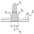
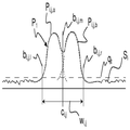
다각형 세트의 생성 및 교차를 위한 전술한 과정은 팬빔 실시형태에서 역시 구현될 수 있음은 물론이다. 도 8a는 이러한 팬빔 실시형태의 예를 도시하되, 6개의 이미터(e1~e6)가 터치 패널의 주변부 주위에서 각각의 인커플링 부위에 위치하고, 각각의 이미터(e1~e6)의 전달 에너지는 터치 패널의 전체 주변부 주위로 연장된 아웃커플링 부위에 위치하는 센서들(미도시)에 의해 측정된다. 그러므로, 각각의 이미터(e1~e6)는 광빔을 생성하고, 상기 광빔은 패널로 주사되어, 이미터로부터 멀리 패널의 평면으로 확장되는 광시트를 각각 형성한다. 도 8a는 또한 터치면 상의 4개의 터치 객체(6)의 외부 경계와 상호작용하는 광선을 도시한다.It goes without saying that the above-described process for generation and intersection of polygon sets can also be implemented in the fanbeam embodiment as well. FIG. 8A shows an example of such a fanbeam embodiment, in which six emitters e1-e6 are located at respective incoupling sites around the periphery of the touch panel, and the transfer energy of each emitter e1-e6. Is measured by sensors (not shown) located at the outcoupling site extending around the entire periphery of the touch panel. Therefore, each of the emitters e1 to e6 produces a light beam, which is then scanned into the panel to form a light sheet that extends away from the emitter into the plane of the panel, respectively. FIG. 8A also shows the light rays interacting with the outer boundaries of the four
도 8b는 각각의 이미터(e1~e6)의 광시트에 대해 획득된 공간 전송 신호에 기반하여 생성된 다각형 세트(A1~A6)를 도시한다. 각각의 다각형 세트(A1~A6)는 대응하는 공간 전송 신호(미도시)의 피크에 대응하는 감쇠 경로, 및 공간 전송 신호와 연관된 데드존을 포함한다. 데드존은 본질적으로 각각의 이미터의 빔 각도에 의해 주어진다. 도 8b의 좌측 부분에서, 실선은 감쇠 경로의 경계를 나타내고, 파선은 데드존의 경계를 나타낸다. 도 8b의 우측 부분에서, 다각형 세트(A1~A6)의 다각형들은 짙은 부분으로 나타낸다.8B shows a polygonal set A 1 -A 6 generated based on the spatial transmission signal obtained for the light sheets of each emitter e1-e6. Each polygon set A 1 -A 6 includes an attenuation path corresponding to a peak of a corresponding spatial transmission signal (not shown), and a dead zone associated with the spatial transmission signal. The dead zone is essentially given by the beam angle of each emitter. In the left part of FIG. 8B, the solid line represents the boundary of the attenuation path and the broken line represents the boundary of the dead zone. In the right part of FIG. 8B, the polygons of the polygon sets A 1 to A 6 are represented by dark portions.
도 9는 도 8b의 다각형 세트들(A1~A6)의 교차 결과를 도시한다. 따라서, 다각형 세트들(A1, A4)은 교차되어 다각형 교차점(A1+4)을 생성하고, 다각형 세트들(A3, A6)은 교차되어 다각형 교차점(A3+6)을 생성하고, 다각형 세트들(A2, A5)은 교차되어 다각형 교차점(A2+5)을 생성한다. 다음으로, 다각형 교차점들(A1+4, A3+6)이 교차되어 다각형 교차점(A1+4+3+6)을 생성하고, 이는 이후 다각형 교차점(A2+5)과 교차되어 최종 교차점(Atotal)을 생성한다.9 shows the result of the intersection of the polygon sets A 1 to A 6 of FIG. 8B. Thus, the polygon sets A 1 , A 4 intersect to create a polygon intersection point A 1 + 4 , and the polygon sets A 3 , A 6 intersect to produce a polygon intersection point A 3 + 6 . The polygon sets A 2 , A 5 are intersected to produce a polygon intersection A 2 + 5 . Next, polygon intersections A 1 + 4 , A 3 + 6 intersect to create polygon intersections A 1 + 4 + 3 + 6 , which then intersect polygon intersections A 2 + 5 and finally Create an intersection (A total ).
최종 교차점(Atotal)은 터치 객체를 포함했을 수 있는 총면적을 나타낸다. 도 9는 이러한 면적이 터치면의 작은 부분을 구성함을 보여준다. 도 9의 최종 교차점(Atotal)을 도 8a와 비교하면, 이러한 특정의 예에서는, 교차 단계가 적절한 (진정한) 터치점에 대응하지 않는 소정의 분석 영역을 야기함을 알 수 있다. 이러한 분석 영역은 후속 재구성 및 터치 식별 단계(도 2의 206~207 단계)에서 제거될 수 있다. 패널을 조명하는 광시트의 개수를 증가시킴으로써, 소정 개수의 진정한 터치점에 대해 분석 영역의 개수를 감소시킬 수 있다.The final intersection point (A total ) represents the total area that may have included the touch object. 9 shows that this area constitutes a small part of the touch surface. Comparing the final intersection A total of FIG. 9 with FIG. 8A, it can be seen that in this particular example, the intersection step results in a predetermined analysis area that does not correspond to an appropriate (true) touch point. This analysis region may be removed in a subsequent reconstruction and touch identification step (steps 206-207 of FIG. 2). By increasing the number of light sheets illuminating the panel, it is possible to reduce the number of analysis regions for a given number of true touch points.
다각형을 생성 및 교차시키는 단계에 대한 많은 대안이 존재함은 물론이다.Of course there are many alternatives to the step of creating and intersecting polygons.
예컨대, 생성 및 교차 단계는 순차적인 순서로 수행되는 것이 아니라 뒤섞일 수 있다. "중심선 교차"로 지칭되는 이러한 일 실시형태에서, 공간 전송 신호는 쌍단위로 처리되고, 각 쌍의 피크 데이터가 조합되어 각각의 다각형 세트를 생성한다. 이러한 피크 데이터는 각각의 피크의 중심점(ci ,j) 및 폭(wi ,j)일 수 있다(도 3a 참조). 이후, 전술한 바와 같이, 결과적인 다각형 세트들이 교차되어 최종 교차점을 생성한다. 중심선 교차 기법은 도 10에 더 예시된다. 도 10a에서, 패널의 하단에서 아웃커플링 부위로부터 연장된 검출선에 관한 지식 및 공간 전송 신호(S5)에서 식별된 피크의 중심점에 기반하여, 3개의 중심선(실선)이 터치 패널을 가로질러 재추적된다. 아울러, 데드존이 도 10a의 중심선 표현에 포함된다. 도 10b에서, 공간 전송 신호(S4)에서 식별된 피크의 중심점에 기반하여 3개의 중심선(실선)이 터치 패널을 가로질러 재추적된다. 2개의 객체가 본질적으로 검출선과 정렬되고, 피크 식별 단계에서 서로 분리되지 않음을 주목할 수 있다. 그러므로, 단일 중심선이 도 10b의 최상위 피크의 중심점으로부터 재추적된다. 도 10c는 도 10a 및 도 10b의 중심선 표현들의 교차 결과를 도시한다. 도 10d에서, 십자점(crossing point)에 대한 각각의 피크의 폭을 재추적함으로써, 중심선의 각각의 십자부 주위에 다각형이 생성되었다. 더욱이, 다각형은 데드존에서도 마찬가지로 생성된다. 따라서, 도 10d의 다각형 세트(A4+5)는 본질적으로 도 6 내지 도 9와 관련하여 설명된 바와 같은 다각형 교차점에 대응한다. 도 10e 및 도 10f는 각각 공간 전송 신호(S1, S2; S3, S6)에 기반하여 생성된 다각형 세트(A1+2; A3+6)를 도시한다. 이후, 도 6 내지 도 9와 관련하여 설명된 바와 같이, 도 10d 내지 도 10f의 다각형 세트들(A4+5, A1+2, A3+6)이 교차되어 도 10g에 도시된 최종 교차점(Atotal)을 생성한다. 중심선 교차 기법은 초기 다각형 세트를 생성하기 위해 공간 전송 신호의 쌍을 이룰 때 검출선들 간의 직교의 최대화로부터 이점을 취할 수 있다(도 10d 내지 도 10f 참조). 이는 십자점의 위치가 공간 전송 신호의 노이즈에 덜 취약하게 만들 수 있다.For example, the generation and intersection steps may be mixed rather than performed in a sequential order. In one such embodiment, referred to as “centerline intersection,” the spatial transmission signal is processed in pairs, and each pair of peak data is combined to produce a respective set of polygons. Such peak data may be the center point c i , j and width w i , j of each peak (see FIG. 3A). Then, as described above, the resulting polygon sets are intersected to produce the final intersection. The centerline crossing technique is further illustrated in FIG. 10. In FIG. 10A, based on the knowledge of the detection line extending from the outcoupling site at the bottom of the panel and the center point of the peak identified in the spatial transmission signal S 5 , three centerlines (solid line) cross the touch panel. Is retraced. In addition, the dead zone is included in the centerline representation of FIG. 10A. In FIG. 10B, three centerlines (solid lines) are retraced across the touch panel based on the center point of the peak identified in the spatial transmission signal S 4 . Note that the two objects are essentially aligned with the detection line and are not separated from each other in the peak identification step. Therefore, a single centerline is retraced from the center point of the highest peak of FIG. 10B. 10C shows the result of the intersection of the centerline representations of FIGS. 10A and 10B. In FIG. 10D, polygons were created around each cross of the centerline by retrace the width of each peak to the crossing point. Moreover, polygons are created in dead zones as well. Thus, the polygon set A 4 + 5 of FIG. 10D essentially corresponds to the polygon intersection point as described in connection with FIGS. 6 to 9. 10E and 10F show the polygon set A 1 + 2 ; A 3 + 6 generated based on the spatial transmission signals S 1 , S 2 ; S 3 , S 6, respectively. Thereafter, as described with respect to FIGS. 6-9, the polygon sets A 4 + 5 , A 1 + 2 , A 3 + 6 of FIGS. 10D-10F intersect and the final intersection shown in FIG. 10G. Create (A total ). The centerline crossing technique can benefit from maximizing the orthogonality between the detection lines when pairing the spatial transmission signal to generate an initial polygon set (see FIGS. 10D-10F). This may make the position of the cross point less vulnerable to noise in the spatial transmission signal.
다른 변형예에서 다각형 생성 단계(204)는 생략된다. 대신, 단계(205)가 터치면의 맵/영상에 기반하여 분석 영역을 획득하도록 변경되고, 맵은 해상도 요소들 또는 픽셀들로 나뉘어진다. 맵 상의 모든 픽셀에 대해, 픽셀이 연관된 검출선을 따라 각각의 공간 전송 신호에 매칭될 때 픽셀이 피크에 속하는지 여부를 검사한다. 픽셀이 모든 검출선에 대해 피크에 속하는 경우, 픽셀은 분석 영역의 일부로 간주된다. 상기 알고리즘에서는 각각의 픽셀과 연관된 검출선의 개수를 계속 카운트할 필요가 있음을 알 수 있다(픽셀이 하나 이상의 데드존 내에 위치하면 개수가 감소한다).In another variant,
또 다른 변형예는 앞서 언급된 다각형 세트(204 단계에서 생성됨)의 사용에 기반하고, 단계(205)는 논리곱 연산으로 모든 다각형 세트의 대응하는 픽셀들을 조합하도록 변경되고, 그에 따라 조합된 픽셀들은 모두 감쇠 경로 또는 데드존에 속하는 경우에만 분석 영역의 일부로 간주된다.Another variant is based on the use of the aforementioned polygon set (created in step 204), and step 205 is modified to combine the corresponding pixels of all polygon sets in an AND operation, whereby the combined pixels are Only if they all belong to the attenuation path or dead zone are considered part of the analysis domain.
픽셀대픽셀 분석을 수반하는 후자의 기법은 소정의 공간 해상도를 달성하는 데에 다각형 교차 기법 및 중심선 교차 기법보다 더 많은 계산을 필요로 할 수 있다.The latter technique involving pixel-to-pixel analysis may require more computation than polygon intersection technique and centerline intersection technique to achieve a given spatial resolution.
중심선 교차 및 픽셀대픽셀 분석 기법이 또한 팬빔 실시형태에서 획득된 공간 전송 신호의 처리를 위해 사용될 수 있음은 물론이다.Of course, centerline crossing and pixel-to-pixel analysis techniques can also be used for processing spatial transmission signals obtained in the fanbeam embodiment.
다각형 교차를 수반하는 모든 실시형태에서, 분석 영역의 부재 시에 조기 종료 메커니즘을 구현하는 것이 가능하다. 구체적으로, 다각형 교차점이 논리곱 연산에 의해 생성되므로, 임의의 다각형 교차점(A3+5, A4+6 등)이 공집합(null set)인 것으로, 다시 말하면 다각형이 없는 것으로 밝혀진 경우, 최종 교차점(Atotal) 역시 공집합일 것으로 결론 내릴 수 있다. 따라서, 다각형 교차점들 중 어느 하나가 공집합인 것으로 밝혀질 때마다, 상기 과정은 단계(208)로 바로 진행되어 좌표 공집합을 출력하고, 새로운 반복을 위해 준비될 수 있다(도 2 참조). 이러한 조기 종료 메커니즘은 또한 공집합에 대해 소정의 다각형 세트를 검사하여, 공집합을 찾아낸 경우 종료될 수 있다. 이는 도 6c의 다각형 세트(A1, A2)와 같이 데드존이 없는 모든 다각형 세트에 적용된다. 이들 다각형 세트 중 어느 하나가 공집합이라면, 최종 교차점(Atotal) 역시 공집합일 것이다. 이는 피크 검출 단계(도 2의 203 단계)가 수직빔(B1, B2; 도 4a)에 대해 획득된 공간 전송 신호(S1, S2) 중 적어도 하나의 모든 피크를 식별하는 데에 실패할 때마다 종료되는 것에 상응한다. 일 실시형태에서, 단계(203)는 다른 공간 전송 신호에 앞서 이러한 공간 전송 신호(S1, S2)를 처리하고, 신호(S1, S2)의 피크를 찾아내는 데에 실패할 때마다 종료되도록 구성된다.In all embodiments involving polygon intersections, it is possible to implement an early termination mechanism in the absence of analysis regions. Specifically, since polygon intersections are generated by logical AND operations, any polygon intersection (A 3 + 5 , A 4 + 6, etc.) is a null set, that is, if it is found that there are no polygons, the final intersection It can be concluded that (A total ) is also an empty set. Thus, whenever any one of the polygon intersections is found to be an empty set, the process proceeds directly to step 208 to output the coordinate empty set and ready for a new iteration (see FIG. 2). This early termination mechanism can also examine a given set of polygons for an empty set and terminate when an empty set is found. This applies to all polygon sets without dead zones, such as polygon sets A 1 and A 2 in FIG. 6C. If either of these polygon sets is empty, then the final intersection point A total will also be empty. This is when the peak detection step (step 203 of FIG. 2 ) fails to identify all peaks of at least one of the spatial transmission signals S 1 , S 2 obtained for the vertical beams B1, B2 (FIG. 4A). Corresponds to ending every time. In one embodiment, step 203 processes these spatial transmission signals S 1 , S 2 before other spatial transmission signals, and ends each time it fails to find the peaks of signals S 1 , S 2 . It is configured to be.
국부 재구성(206 단계)Local reconstruction (step 206)
재구성 단계에서 분석 영역은 터치점의 존재를 식별하기 위해 처리된다. 재구성 단계는 통상 분석 영역 내의 에너지값/감쇠값/전달값의 공간 분포를 나타내는 공간 분포도를 생성하는 단계를 수반한다. 이러한 공간 분포도는 전체 터치면을 가로질러 공간 분포도를 재구성하는 데에 사용될 수 있는 기존의 모든 영상 재구성 기법을 적합화하여 생성될 수 있고, 그로 인해 공간 분포도는 분석 영역에만 국부적으로 생성된다.In the reconstruction step, the analysis area is processed to identify the presence of the touch point. The reconstruction step usually involves generating a spatial distribution representing the spatial distribution of energy values / damping values / transmission values within the analysis region. This spatial distribution can be generated by adapting all existing image reconstruction techniques that can be used to reconstruct the spatial distribution across the entire touch plane, whereby the spatial distribution is locally generated only in the analysis region.
이 예에서, 여과후 역투사와 같은 표준 단층촬영 방식은 분석 영역 내의 국부 재구성을 위해 적합화될 수 있다. 단층촬영 재구성의 원리는 당해 기술분야에 주지되어 있다. 이는 Frank Natterer와 Frank Wubbeling의 "Mathematical Methods in Image Reconstruction" 및 Kak과 Slaney의 "Principles of Computerized Tomographic Imaging"과 같은 교재에 철저히 기재되어 있다.In this example, standard tomography schemes such as post-filtration reverse projection can be adapted for local reconstruction within the analysis region. The principle of tomographic reconstruction is well known in the art. This is described thoroughly in textbooks such as "Mathematical Methods in Image Reconstruction" by Frank Natterer and Frank Wubbeling, and "Principles of Computerized Tomographic Imaging" by Kak and Slaney.
평행 검출선(스캔빔 실시형태에서 획득됨)을 가진 설정 및 분기 검출선(팬빔 실시형태에서 획득됨)을 가진 설정 간의 구현상의 차이뿐만 아니라 여과후 역투사 알고리즘의 철저한 설명을 위해 앞서 제시된 교재들을 참조한다. 여기서, 국부 재구성을 위해 적합화된 알고리즘의 주요 단계의 대강의 개요를 제공하고, 분석 영역의 이용으로부터 이점을 취할 수 있는 방법을 보여줄 것이다.For a thorough explanation of the post-filtering back projection algorithm, as well as implementation differences between the settings with parallel detection lines (obtained in the scanbeam embodiment) and the settings with branch detection lines (obtained in the fanbeam embodiment) See. Here, we will provide a rough overview of the main steps of the algorithms adapted for local reconstruction, and show how to benefit from the use of the analysis domain.
일반적으로, 여과후 역투사 알고리즘은 소위 투사 신호에 적용되며, 이는 통상 (그러나 반드시는 아님) 전송 또는 대수 전송(logarithmic transmission)으로 변환되는 앞서 언급된 공간 전송 신호에 대응할 수 있다(이하를 참조한다). 알고리즘이 전체 터치면의 재구성을 위해 적용되는 경우, 각각의 투사 신호에 대해 다음과 같이 작용한다:In general, the post-filtration back-projection algorithm is applied to the so-called projection signal, which may correspond to the previously mentioned spatial transmission signal which is usually (but not necessarily) transmission or logarithmic transmission (see below). ). When the algorithm is applied for reconstruction of the entire touch surface, it works as follows for each projection signal:
1. 투사 신호에 적절한 필터를 적용한다. 적절한 필터는 문헌 내에 발견되지만, 예컨대 람-락(Ram-Lak) 또는 쉐프-로간(Shepp-Logan)일 수 있다. 필터는 푸리에 평면 또는 공간 도메인에 적용될 수 있다.1. Apply the appropriate filter to the projection signal. Suitable filters are found in the literature, but can be, for example, Ram-Lak or Shepp-Logan. The filter can be applied to the Fourier plane or the spatial domain.
2. 공간 분포도의 모든 지점/픽셀에 대해, 재구성된 신호값이 모든 여과된 투사 신호에 대한 픽셀의 상호작용의 합으로 계산된다. 이를 역투사 과정이라 한다.2. For every point / pixel in the spatial distribution, the reconstructed signal value is calculated as the sum of the interactions of the pixels for all filtered projection signals. This is called a reverse projection process.
공간 전송 신호 세트에 기반하는 이러한 전체 재구성에 의해 생성된 공간 분포도의 예가 도 11a의 3차원 도표에 제공되고, 이는 터치 패널의 XY 좌표 시스템의 재구성된 감쇠값을 보여준다.An example of the spatial distribution produced by this overall reconstruction based on a set of spatial transmission signals is provided in the three-dimensional diagram of FIG. 11A, which shows the reconstructed attenuation values of the XY coordinate system of the touch panel.
국부 재구성을 위한 역투사 알고리즘을 적합화하기 위해, 두 번째 단계는 역투사 과정 동안 전체 터치 평면 내의 픽셀의 합을 계산하는 것이 아니라, 분석 영역 내의 픽셀의 합만을 계산하도록 변경될 수 있다. 도 11b는, 도 11a의 전체 재구성을 생성하기 위해 사용된 공간 전송 신호 세트에 기반하여 다각형 생성 및 교차 단계(204~205)에 의해 계산된 최종 교차점(Atotal)을 도시한다. 도시된 바와 같이, 최종 교차점은 5개의 분석 영역을 가져온다. 도 11c는 분석 영역 내의 국부 재구성의 결과를 도시한다. 도 11a를 도 11c와 비교하면, 국부 재구성은 터치 패널의 관련 부분 내에서 전체 재구성과 동일한 결과를 가져옴을 알 수 있다. 또한, 적절한 국부 재구성 알고리즘을 선택함으로써, 노이즈 레벨을 저감하는 것이 가능함을 알 수 있다. 여과후 역투사에서, 예컨대 투사 신호(즉, 공간 전송 신호)는 관련 피크의 외부에서 감쇠율을 0으로 설정함으로써(또는 전달률을 1로 설정함으로써), 분석 영역에 기반하여 재구성 전에 노이즈 감소를 위해 사전처리될 수 있다. 이러한 사전처리는 앞서 언급된 필터(예컨대, 람-락 또는 쉐프-로간)를 적용하기 전에 이행될 수 있다. 아울러, 국부 재구성 과정은 전체 재구성보다 더 많이 중복결정될 수 있는데, 이는 재구성이 분석 영역에 제한되는 경우 다수의 미지수가 제거될 수 있기 때문이다. 숙련자들은 증가된 정보를 이용하도록 재구성 과정을 적절하게 설계함으로써 추가 노이즈 감소가 가능함을 알 것이다.In order to adapt the reverse projection algorithm for local reconstruction, the second step can be modified to calculate only the sum of the pixels in the analysis area, not the sum of the pixels within the entire touch plane during the reverse projection process. FIG. 11B shows the final intersection A total calculated by polygon generation and intersection steps 204-205 based on the set of spatial transmission signals used to generate the overall reconstruction of FIG. 11A. As shown, the final intersection results in five areas of analysis. 11C shows the results of local reconstruction within the analysis region. Comparing FIG. 11A with FIG. 11C, it can be seen that local reconstruction has the same result as overall reconstruction within the relevant portion of the touch panel. It can also be seen that by selecting an appropriate local reconstruction algorithm, it is possible to reduce the noise level. In reverse projection after filtration, for example, the projection signal (i.e. the spatial transmission signal) is pre-set for noise reduction before reconstruction based on the analysis region, by setting the attenuation rate to zero (or by setting the transmission rate to 1) outside the relevant peak. Can be processed. This pretreatment can be carried out before applying the aforementioned filters (eg, lamb-lock or chef-logan). In addition, the local reconstruction process can be duplicated more than the full reconstruction, because a large number of unknowns can be eliminated if the reconstruction is limited to the analysis domain. Those skilled in the art will appreciate that additional noise reduction is possible by properly designing the reconstruction process to take advantage of the increased information.
터치 결정 과정 동안 처리의 필요성이 주로 두 번째 단계, 즉 실제 재구성에 의해 야기됨을 강조해야 한다. 대부분의 단층촬영 재구성 기법에 대해, 이러한 처리는 재구성된 영상(즉, 공간 분포도)의 지점(픽셀)의 개수 및 투사 신호의 개수와 비례한다. 이론적 근거는 전술한 알고리즘에서 찾아볼 수 있다. 공간 분포도의 모든 지점에 대해, 모든 투사 신호로부터의 역투사값을 추가해야 한다. 재구성이 분석 영역에만 제한되는 경우, 재구성된 공간 분포도의 지점의 개수가 감소한다. 도 2와 관련하여, 본 발명의 실시형태들은 40인치 터치 패널 상에서 10번의 터치에 대해 약 44배 감소된 재구성 처리를 가능하게 한다는 것이 설명되었다. 동일한 터치 패널 상에 4번의 터치가 있는 경우, 처리는 275배까지 감소할 수 있고, 패널 상에 단지 2번의 터치만 있다면, 처리는 적어도 1100배까지 감소한다.It should be emphasized that the need for processing during the touch decision process is mainly caused by the second step, the actual reconstruction. For most tomography reconstruction techniques, this processing is proportional to the number of points (pixels) and the number of projection signals of the reconstructed image (ie, spatial distribution). The theoretical basis can be found in the algorithm described above. For all points in the spatial distribution, the back projection from all projection signals must be added. If the reconstruction is limited to the analysis area only, the number of points in the reconstructed spatial distribution is reduced. With reference to FIG. 2, it has been described that embodiments of the present invention enable about 44 times reduced reconstruction processing for 10 touches on a 40 inch touch panel. If there are four touches on the same touch panel, the process can be reduced by 275 times, and if there are only two touches on the panel, the process is reduced by at least 1100 times.
국부 재구성이 여과후 역투사 알고리즘의 사용에 제한되지 않음을 강조해야 한다. 본질적으로, 컴퓨터 단층촬영(CT), 대수적 영상구성 기법(ART), 동시반복 영상구성 기법(SIRT), 동시대수적 영상구성 기법(SART), 직접 2D FFT 영상구성, 또는 예컨대 베이지안 역산에 기반하는 통계적 영상구성 기법을 포함하지만 이에 제한되지 않는 기존의 영상 재구성 기법을 사용할 수 있다. 영상 재구성 기법의 실시형태들은 본 출원인에 의해 2009년 10월 19일자로 출원된 미국 가출원번호 제61/272,667호 및 2010년 5월 3일자로 출원된 미국 가출원번호 제61/282,973호에 더 기재되어 있으며, 양자의 개시내용이 이에 참조로서 통합된다.It should be emphasized that local reconstruction is not limited to the use of the post-projection backprojection algorithm. In essence, computed tomography (CT), algebraic imaging (ART), co-repeated imaging (SIRT), simultaneous algebraic imaging (SART), direct 2D FFT imaging, or statistically based on Bayesian inversion, for example. Existing image reconstruction techniques can be used, including but not limited to image composition techniques. Embodiments of the image reconstruction technique are further described in US Provisional Application No. 61 / 272,667 filed Oct. 19, 2009 by Applicant and US Provisional Application No. 61 / 282,973 filed May 3, 2010. And both disclosures are incorporated herein by reference.
국부 재구성의 일반적인 이점은, 후속 터치 식별 단계(207)에서 분석 영역들 중에서 진정한 터치점과 허위 터치점의 구별을 가능하게 한다는 것이다. 그러므로, 완전히 또는 부분적으로 중복된 피크들이 단계(203)에서 식별 및 분리되지 않는 경우, 이러한 피크들은 단계(205)에서 복수의 분석 영역을 가져올 것이고, 이들은 단계(206)의 재구성 이후 단계(207)에서 진정한 터치점의 식별을 위해 처리된다.A general advantage of local reconstruction is that in subsequent
터치 식별 및 데이터 추출(207~208 단계)Touch Identification and Data Extraction (
국부 재구성 단계(206)의 완료 후, 공간 분포도 내의 진정한(실제) 터치점을 분리하기 위해 모든 주지의 기법을 사용할 수 있다. 예컨대, 실제 터치점을 찾아내기 위해 보통의 블롭 검출 및 추적 기법을 사용할 수 있다. 그러나, 선행하는 국부 재구성 단계가 터치점의 추출을 위해 필요한 처리를 감소시킴을 인식해야 한다.After completion of the
일 실시형태에서는, 먼저 노이즈를 제거하기 위해 임계값이 공간 분포도에 적용된다. 임계값 위로 상승된 모든 영역은, 예컨대 2차원 가우시안 벨 형상을 영역 내의 신호값에 삽입하거나, 또는 영역 내의 신호값의 가중 관성 타원을 찾아냄으로써, 중심 및 형상을 찾아내도록 더 처리될 수 있다. 또한, 2차원 2차 다항식, K-평균 클러스터링, 가우시안-라플라시안(LoG), 및 워터쉐드 알고리즘의 삽입을 포함하지만 이에 제한되지 않는 다수의 기법이 당해 기술분야에 주지되어 있다.In one embodiment, a threshold is first applied to the spatial distribution to remove noise. All areas raised above the threshold may be further processed to find the center and shape, for example, by inserting a two-dimensional Gaussian bell shape into the signal values in the area, or by finding a weighted inertia ellipse of the signal values in the area. In addition, many techniques are well known in the art, including, but not limited to, insertion of two-dimensional quadratic polynomials, K-means clustering, Gaussian-Laplacian (LoG), and watershed algorithms.
공간 분포도는 임의의 유형의 터치 데이터를 추출하기 위해 처리될 수 있다. 이러한 터치 데이터는 터치면의 좌표 시스템 내의 각각의 터치 객체의 좌표를 포함할 수 있다. 다른 유형의 터치 데이터는 각각의 터치 객체의 면적 및/또는 형상을 포함한다. 면적은 인가된 압력의 함수이므로, 적어도 유연한 객체(예컨대, 손가락 끝)에 대해서는, 객체와 터치면 간의 접촉 압력이 각각의 터치 객체에 대해 추정될 수도 있다.The spatial distribution can be processed to extract any type of touch data. Such touch data may include the coordinates of each touch object in the coordinate system of the touch surface. Another type of touch data includes the area and / or shape of each touch object. Since the area is a function of the applied pressure, for at least a flexible object (eg, a fingertip), the contact pressure between the object and the touch surface may be estimated for each touch object.
더욱이, 단계(208)는 예컨대 면적 및/또는 형상에 기반하는 소정의 객체에 대한 터치 데이터의 출력을 억제할 수 있다. 예컨대, 손바닥에 대한 터치 데이터는 출력되지 않는 것이 바람직하지만, 손가락 끝에 대한 터치 데이터는 출력되어야 한다.Moreover, step 208 can suppress the output of touch data for a given object based, for example, on area and / or shape. For example, it is preferable that touch data for a palm is not output, but touch data for a fingertip should be output.
또 다른 실시형태에서, 공간 분포도에서 검출되는 모든 터치점은 선행하는 반복(도 2의 반복 참조)에서 검출된 터치에 매칭된다. 많은 응용에서, 터치점이 시간 순서적인 터치점들의 일부인 것을 알면 유용할 수 있다. 이는 예컨대 터치면의 터치 제스처 등의 인식을 용이하게 할 수 있다.In another embodiment, all touch points detected in the spatial distribution map match the detected touches in the preceding iterations (see repetition of FIG. 2). In many applications, it may be useful to know that a touch point is part of a time-sequential touch point. This can facilitate the recognition of touch gestures on the touch surface, for example.
앞서 언급된 바와 같이, 국부 재구성 단계(206)는 생략될 수 있고, 터치 식별 단계(207)는 단계(205)에서 식별된 분석 영역에 직접 적용될 수 있다. 이러한 변형예는 특히 가능한 터치점의 수가 제한되고 패널의 광시트의 교차 수보다 적을 때에는 언제나 있음직하다. 예컨대, 터치 객체의 형상 및/또는 면적이 주지되어 있거나 예상 가능한 경우, 분석 영역의 형상 및/또는 크기에 기반하여 분석 영역들 중에서 진정한 터치점을 허위 터치점과 구별할 수 있다.As mentioned above, the
도 12a는 본원에 설명된 바와 같은 터치 감지 장치의 터치 결정 방법의 일 실시형태를 도시한다. 상기 방법은, 터치 감지 장치의 아웃커플링 부위 내의 광의 공간 분포를 각각 나타내는 하나 이상의 투사 신호를 획득하는 단계(1200), 및 하나 이상의 터치 객체에 의해 야기된 감쇠를 나타내는 모든 신호 프로파일의 식별을 위해 투사 신호(들)을 처리하는 단계(1202)를 포함한다. 상기 방법은, 각각의 신호 프로파일에 대해 터치면을 가로질러 감쇠 경로를 결정하는 단계(1204), 및 터치면 상의 하나 이상의 후보 터치 영역을 결정된 감쇠 경로 세트의 함수로 식별하는 단계로, 각각의 후보 터치 영역은 터치면의 부분집합인 단계(1206)를 더 포함한다. 상기 방법은 후보 터치 영역에 기반하여 각각의 터치 객체에 대한 터치 데이터를 결정하는 단계(1208)에 의해 완료된다.12A illustrates one embodiment of a touch determination method of a touch sensitive device as described herein. The method comprises obtaining 1200 one or more projection signals, each representing a spatial distribution of light in an outcoupling portion of the touch sensing device, and identifying all signal profiles indicative of attenuation caused by one or more touch objects. Processing 1202 the projection signal (s). The method includes determining 1204 attenuation paths across the touch surface for each signal profile, and identifying one or more candidate touch regions on the touch surface as a function of the determined set of attenuation paths, each candidate. The touch region further includes
도 12b는 본원에 설명된 바와 같은 터치 감지 장치의 터치 결정 방법의 다른 실시형태를 도시한다. 도 12b의 방법은, 하나 이상의 투사 신호를 획득하는 단계(1200), 및 하나 이상의 투사 신호(들)의 신호 프로파일을 식별하는 단계(1202)를 포함한다. 상기 방법은, 신호 프로파일에 기반하여 터치면 상의 하나 이상의 후보 터치 영역을 식별하는 단계(1206'), 및 후보 터치 영역(들) 내의 2차원 분포된 신호값을 재구성하기 위해 투사 신호(들)을 처리하는 단계(1207)를 더 포함한다. 상기 방법은 후보 터치 영역에 기반하여 각각의 터치 객체에 대한 터치 데이터를 결정하는 단계(1208)에 의해 완료된다.12B illustrates another embodiment of a touch determination method of a touch sensitive device as described herein. The method of FIG. 12B includes obtaining 1200 one or more projection signals, and identifying 1202 a signal profile of one or more projection signal (s). The method includes identifying 1206 'one or more candidate touch regions on the touch surface based on the signal profile, and generating projection signal (s) to reconstruct the two-dimensional distributed signal value within the candidate touch region (s). Processing further includes
터치 결정 단계는 일반적으로 터치 감지 장치에서 광센서(들)의 출력 신호(들)을 수신하도록 연결된 데이터 처리 장치(도 1a의 7 참조)에 의해 수행된다. 도 13a는 도 12b의 과정을 수행하는 데이터 처리 장치(7)의 예를 도시한다. 도시된 예에서, 상기 장치(7)는, 하나 이상의 투사 신호를 획득하는 요소(또는 수단)(1300), 및 하나 이상의 터치 객체에 의해 야기된 감쇠를 나타내는 모든 신호 프로파일의 식별을 위해 투사 신호(들)을 처리하는 요소(또는 수단)(1302)을 포함한다. 또한, 신호 프로파일에 기반하여 터치면 상의 하나 이상의 후보 터치 영역을 식별하는 요소(또는 수단)(1304), 및 후보 터치 영역(들) 내의 2차원 분포된 신호값을 재구성하기 위해 투사 신호(들)을 처리하는 요소(또는 수단)(1306)도 구비된다. 장치(7)는 후보 터치 영역에 기반하여 각각의 터치 객체에 대한 터치 데이터를 결정하는 요소(또는 수단)(1308)을 더 포함한다.The touch determination step is generally performed by a data processing device (see 7 of FIG. 1A) connected to receive the output signal (s) of the optical sensor (s) in the touch sensing device. FIG. 13A shows an example of the
장치(7)는 하나 이상의 범용 또는 특수 컴퓨팅 장치에서 실행되는 특수 소프트웨어(또는 펌웨어)에 의해 구현될 수 있다. 이러한 맥락에서, 이러한 컴퓨팅 장치의 각각의 "요소" 또는 "수단"은 방법 단계의 개념적인 균등물을 가리킴을 이해해야 한다. 즉, 요소/수단과 하드웨어 또는 소프트웨어 루틴의 특정 부분 간에 항상 일대일 대응이 존재하지는 않는다. 하드웨어의 일 부분은 종종 다양한 수단/요소를 포함한다. 예를 들어, 처리부는 하나의 명령을 실행하는 경우 하나의 요소/수단의 역할을 하지만, 다른 명령을 실행하는 경우에는 다른 요소/수단의 역할을 한다. 또한, 하나의 요소/수단은 일부 경우에서는 하나의 명령에 의해 구현될 수 있지만, 다른 경우에서는 복수의 명령에 의해 구현될 수 있다. 도 13b에 도시된 바와 같이, 이러한 소프트웨어로 제어되는 컴퓨팅 장치(7)는, 중앙처리부(CPU), 디지털 신호 처리기(DSP), 주문형 집적회로(ASIC), 이산 아날로그 및/또는 디지털 부품, 또는 필드 프로그래머블 게이트 어레이(FPGA)와 같은 일부 다른 프로그램 가능한 논리 장치 등과 같은 하나 이상의 처리부(1320)를 포함할 수 있다. 컴퓨팅 장치(7)는 시스템 메모리(1322), 및 시스템 메모리(1322)를 포함하는 다양한 시스템 부품을 처리부(1320)에 결합시키는 시스템 버스(1324)를 더 포함할 수 있다. 시스템 버스(1324)는, 다양한 버스 아키텍처 중 어느 하나를 사용하는 메모리 버스 또는 메모리 제어기, 주변 버스, 및 로컬 버스를 포함하는 여러 유형의 버스 구조 중 하나 일 수 있다. 시스템 메모리(1322)는 읽기전용 메모리(ROM), 랜덤 액세스 메모리(RAM) 및 플래시 메모리와 같은 휘발성 및/또는 비휘발성 메모리 형태의 컴퓨터 저장 매체를 포함할 수 있다. 특수 소프트웨어는, 자기매체, 광매체, 플래시 메모리 카드, 디지털 테이프, 솔리드 스테이트 RAM, 솔리드 스테이트 ROM 등과 같이 컴퓨팅 장치에 포함되거나 이에 액세스 가능한 시스템 메모리 또는 다른 탈착식/비탈착식 휘발성/비휘발성 컴퓨터 저장 매체에 저장될 수 있다. 컴퓨팅 장치(7)는, 직렬 인터페이스, 병렬 인터페이스, USB 인터페이스, 무선 인터페이스, 네트워크 어댑터 등과 같은 하나 이상의 통신 인터페이스(1326), 및 A/D 컨버터와 같은 하나 이상의 데이터 획득 장치(1328)를 포함할 수 있다. 특수 소프트웨어는, 기록 매체, ROM, 또는 전기적 캐리어 신호를 포함하는 임의의 적절한 컴퓨터 판독 가능한 매체를 통해 컴퓨팅 장치에 제공될 수 있다.The
전술한 모든 실시형태에서, 이미터는 임의의 적절한 파장 범위, 예컨대 적외선 또는 가시광선 파장 영역에서 작동될 수 있다. 모든 광시트는 동일한 파장으로 생성될 수 있다. 대안으로, 다양한 시트들이 다양한 파장 범위를 가진 광으로 생성될 수 있고, 그에 따라 시트들은 파장을 기반으로 구별될 수 있다. 아울러, 이미터는 연속적이거나 펄스화된 복사를 출력할 수 있다. 더욱이, 이미터는 동시에 또는 순차적으로 활성화될 수 있다. 다이오드 레이저, 수직공동 표면발광 레이저(VCSEL), 발광 다이오드(LED), 백열 램프, 할로겐 램프 등과 같이, 원하는 파장 범위에서 광을 방출할 수 있는 모든 유형의 이미터가 사용될 수 있다.In all the embodiments described above, the emitter can be operated in any suitable wavelength range, such as in the infrared or visible wavelength range. All light sheets can be produced with the same wavelength. Alternatively, various sheets can be produced with light having various wavelength ranges, whereby the sheets can be distinguished based on wavelength. In addition, the emitter can output continuous or pulsed radiation. Moreover, the emitters can be activated simultaneously or sequentially. All types of emitters capable of emitting light in the desired wavelength range can be used, such as diode lasers, vertical cavity surface emitting lasers (VCSELs), light emitting diodes (LEDs), incandescent lamps, halogen lamps and the like.
전달되는 에너지는 광을 전기 신호로 변환할 수 있는 모든 유형의 광센서에 의해 측정될 수 있다. 본 명세서의 맥락에서, "광센서"는 0차원의 광검출기를 의미함을 주목해야 한다. 따라서, 광센서(3; 도 1b)는 CCD 또는 CMOS 검출기 상의 픽셀 또는 광검출기와 같은 단일의 광감지 요소일 수 있다. 대안으로, 광센서(3)는, 하드웨어 또는 소프트웨어 내의 개별 요소들의 출력을 합산하거나 평균을 구함으로써, 0차원 광검출을 위해 조합되는 광감지 요소군에 의해 형성될 수 있다.The energy delivered can be measured by any type of light sensor capable of converting light into an electrical signal. In the context of this specification, it should be noted that "light sensor" means a 0-dimensional photodetector. Thus, the optical sensor 3 (FIG. 1B) may be a single light sensing element such as a pixel or photodetector on a CCD or CMOS detector. Alternatively, the
투광성 패널(1)은, 전달되는 에너지의 감지 측정을 허용하기에 충분하도록 관련 파장 범위의 광량을 전달하는 임의의 재료로 이루어질 수 있다. 이러한 재료는 유리, 폴리(메틸메타크릴레이트)(PMMA) 및 폴리카보네이트(PC)를 포함한다. 패널(1)은 단일 재료로 이루어지거나 다양한 재료층들에 의해 형성될 수 있다. 터치면의 내부 반사는 패널 재료와 주변 매체, 통상 공기 간의 굴절률 차이로 인한 내부 전반사(TIR)에 의해 야기된다. 반대편 경계면의 반사는 TIR, 또는 반대편 경계면에 도포된 반사 코팅재에 의해 야기될 수 있다.The
출력 신호의 정규화Normalization of the Output Signal
전술한 바와 같이, 공간 전송 신호는 백그라운드 신호를 이용한 정규화를 통해 획득될 수 있다. 백그라운드 신호는 통상 객체가 패널을 터치하지 않는 경우의 전달 에너지를 나타내고, 그에 따라 각각의 아웃커플링 부위에서의 광의 공간 분포를 나타낸다. 백그라운드 신호는 각각의 검출기/아웃커플링 부위 또는 각각의 출력 신호에 대해 고유하거나 고유하지 않을 수 있다. 백그라운드 신호는 사전 설정되거나, 별개의 교정 단계 중에 유도되거나, 또는 하나 이상의 선행하는 반복 중에 획득된 출력 신호 세트(객체가 패널을 터치하지 않음)의 평균을 구함으로써 상기 출력 신호로부터 유도될 수 있다.As described above, the spatial transmission signal may be obtained through normalization using a background signal. The background signal typically represents the transfer energy when the object does not touch the panel, and thus the spatial distribution of light at each outcoupling site. The background signal may or may not be unique for each detector / outcoupling site or each output signal. The background signal can be preset, derived during a separate calibration step, or derived from the output signal by averaging the set of output signals (objects do not touch the panel) obtained during one or more preceding iterations.
공간 전송 신호의 계산을 더 예시하기 위해, 도 14a는 패널을 터치하는 단일 객체에 의해 획득된 비정규화된 공간 전송 신호(S1)를 보여주되, 이는 아웃커플링 부위 내의 위치의 함수로서 전달 에너지의 도표로 주어진다. 도 14b는 대응하는 백그라운드 신호(REF)를 보여주되, 이 또한 아웃커플링 부위 내의 위치의 함수로서 전달 에너지의 도표로 주어진다. 이 예에서, 아웃커플링 부위 내의 복사 분포는 상당히 비균일하다. 도 14c는 결과적인 정규화된 공간 전송 신호(T1=Si/REF)를 보여주고, 그에 따라 약 1의 (상대) 전달률에서 피크(P1 ,1)를 가진 본질적으로 균일한 신호 레벨이 터치 객체에 의해 야기된다. 정규화된 공간 전송 신호로의 변환이 관련 피크의 식별을 훨씬 용이하게 함은 물론이다. 이는 또한 상이한 아웃커플링 부위에서 및/또는 상이한 빔에 대해 획득된 신호들의 피크 비교를 가능하게 한다. 변형예에서는, 공간 전송 신호가 전달률 대신에 1-T1로 주어진 감쇠율을 나타내도록 변환된다.To further illustrate the calculation of the spatial transmission signal, FIG. 14A shows the denormalized spatial transmission signal S 1 obtained by a single object touching the panel, which is a transfer energy as a function of position within the outcoupling site. Given in the diagram. 14B shows the corresponding background signal REF, which is also given as a plot of the transfer energy as a function of position in the outcoupling site. In this example, the radiation distribution in the outcoupling site is quite nonuniform. 14C shows the resulting normalized spatial transmission signal (T 1 = S i / REF), whereby an essentially uniform signal level with a peak P 1 , 1 at a (relative) rate of about 1 touches. Caused by the object. It goes without saying that the conversion to a normalized spatial transmission signal makes the identification of related peaks much easier. This also allows for a peak comparison of the signals obtained at different outcoupling sites and / or for different beams. In a variant, the spatial transmission signal is transformed to exhibit an attenuation rate given by 1-T 1 instead of a transmission rate.
앞서 언급된 바와 같이, 동일한 검출선 상에 3개 이상의 터치점이 존재하는 경우, 총전송 신호는 터치점들의 개별 전달률들의 곱이다. 나머지 빔이 아웃커플링점(및 센서)에 도달하는 경우, 이는 임의의 검출선 상의 임의의 개수의 객체에 해당된다. 그러므로, 정규화된 공간 전송 신호에 적용됨으로써, 개별 터치 객체로부터 공간 전송 신호의 피크에 대한 기여도를 분리하는 것이 가능하다.As mentioned above, when there are three or more touch points on the same detection line, the total transmitted signal is the product of the individual transfer rates of the touch points. When the remaining beam reaches the outcoupling point (and sensor), this corresponds to any number of objects on any detection line. Therefore, by being applied to the normalized spatial transmission signal, it is possible to separate the contribution to the peak of the spatial transmission signal from the individual touch objects.
숙련자들은 검출선을 따른 총전달률의 대수가 검출선 상의 터치점들의 개별 전달률들의 대수의 합과 같기 때문에, 터치 결정이 대수(임의의 베이스)에 적용됨으로써 단순화됨을 알 것이다. 아울러, 대수에 적용됨에 따라, 정규화는 나눗셈 연산이 아닌 뺄셈 연산(log(T1)=log(S1)-log(REF))에 의해 수행될 수 있다. 그러나, 대수를 사용할 필요는 없다.Those skilled in the art will appreciate that since the logarithm of the total transfer rate along the detection line is equal to the sum of the logarithms of the individual transfer rates of the touch points on the detection line, touch determination is simplified by applying it to the logarithm (any base). In addition, as applied to algebra, normalization may be performed by a subtraction operation log (T 1 ) = log (S 1 ) -log (REF) rather than a division operation. However, it is not necessary to use algebra.
분산의 사용Use of variance
본 출원인은 광산란 효과를 고려하여 터치 결정 과정을 설계함으로써 터치 결정을 개선할 수 있음을 인식하였다.The Applicant has recognized that the touch determination can be improved by designing the touch determination process in consideration of the light scattering effect.
광산란은 터치면(4) 상의 소위 방현성(Anti-Glare) 구조라 불리는 확산 표면 구조에 의해 야기될 수 있다. AG 구조는 터치면 상의 외부 조명의 눈부심을 저감하기 위해 사용될 수 있다. 더욱이, 터치 객체가 손가락인 경우, 손가락과 터치면 간의 접촉은 일반적으로 터치면 상에 지문을 남긴다. 완전히 평평한 표면에서 이러한 지문은 또렷하게 보이고 흔히 원치 않는 것이다. AG 구조를 터치면에 추가함으로써 지문의 가시성이 감소한다. 아울러, AG 구조가 사용되는 경우, 손가락과 터치면 간의 마찰이 감소하여 사용자의 경험이 개선될 수 있다. AG 구조는 광택부(Gloss Unit)로 명시되며, GU값의 감소는 눈부심의 감소로 이어진다.Light scattering can be caused by a diffuse surface structure called the anti-glare structure on the
경계면 중 하나 또는 양자에 AG 구조를 가진 투광성 패널에서 광빔이 내부 반사에 의해 진행되는 경우, 이러한 산란 경계면에 대한 각각의 내부 반사로 인해, 일부 광이 빔의 주요 방향으로부터 멀리 향하게 되고, 또한 복사가 경계면을 통해 빠져나갈 수 있다.When a light beam is directed by internal reflections in a translucent panel having an AG structure at one or both of the interfaces, due to the respective internal reflections on these scattering interfaces, some light is directed away from the main direction of the beam and also the radiation is You can exit through the interface.
광산란은 예컨대 투광성 패널 상의 다른 유형의 코팅재, 층 또는 표면 구조, 패널 또는 연관된 광부품의 결함 또는 결점, 패널의 경계면 상의 오염(지문, 먼지 등), 터치 감지 장치 내의 회절 효과 등의 다른 원인에 의한 것일 수 있다.Light scattering is caused by other causes such as, for example, other types of coatings, layers or surface structures on translucent panels, defects or defects on the panel or associated optical components, contamination (fingerprints, dust, etc.) on the interface of the panels, diffraction effects in the touch sensing device, etc. It may be.
근원과는 상관없이, 본 출원인이 알아낸 바에 따르면, 광산란은 일반적으로 빔이 패널 상의 진입점(들)로부터 진행될 때 패널의 평면에서 넓어지게 한다. 이러한 넓어짐으로 인해, 공간 전송 신호의 터치 시그너처의 형상은 패널 상의 터치 객체의 위치, 구체적으로 터치 객체와 관련 인커플링점/진입점 간의 거리에 따라 좌우된다. 도 15a는 터치 객체에 의해 야기된 터치 시그너처의 폭 및 터치 객체와 진입점 간의 거리 사이의 예시적인 의존성을 도시한다. 터치 객체의 실제 폭은 Wn이다. 터치 객체가 진입점에 가까이 위치할 때, 검출된 터치 시그너처는 뚜렷하고 실제 폭과 유사한 폭을 가질 것이다. 터치 객체가 진입점으로부터 멀리 이동함에 따라, 검출된 터치 시그너처는 점차 넓어질 것이다. 아웃커플링점에 가까워짐에 따라, 터치 시그너처의 폭은 다시 약간 작아질 수 있다. 폭과 터치 위치 간의 실제 함수 의존성은 터치 감지 장치의 실제 광학 설계에 따라 굉장히 좌우된다는 것과 도 15a는 단지 예로서 제공된 것임을 이해해야 한다.Regardless of the source, as found by the applicant, light scattering generally causes the beam to widen in the plane of the panel as it travels from the entry point (s) on the panel. Due to this widening, the shape of the touch signature of the spatial transmission signal depends on the position of the touch object on the panel, specifically the distance between the touch object and the associated incoupling / entry point. FIG. 15A shows an example dependency between the width of the touch signature caused by the touch object and the distance between the touch object and the entry point. The actual width of the touch object is W n . When the touch object is located close to the entry point, the detected touch signature will have a distinct and similar width to the actual width. As the touch object moves away from the entry point, the detected touch signature will gradually widen. As it approaches the outcoupling point, the width of the touch signature may again be slightly smaller. It should be understood that the actual function dependence between the width and the touch position depends heavily on the actual optical design of the touch sensing device and that FIG. 15A is provided only as an example.
도 15a에서, 진입점과 아웃커플링점 사이의 중간에 위치하는 작은 터치 객체는 진입점에 더 가까이 위치하는 더 큰 터치 객체와 동일한 터치 시그너처 폭을 산출함을 알 수 있다. 도 15a의 데이터에 기반하면, 소정의 터치 시그너처의 폭을 터치 객체와 진입점 간의 거리의 함수로 산출하는 터치 객체의 실제 폭을 결정하는 것이 가능하다. 이러한 유형의 함수 의존성은 후술하는 내용에서 분산 함수로 지칭된다. 도 15b는 도 15a의 데이터에 대해 결정된 분산 함수의 그래프이다. 따라서, 도 15b는 상이한 위치에서의 실제 객체 폭을 도시하되, 이는 공간 전송 신호에서 동일한 터치 시그너처 폭을 생성할 것이다. 이하에 더 설명되는 바와 같이, 이러한 분산 함수는 터치 결정 과정을 개선하도록 사용될 수 있다.In FIG. 15A, it can be seen that a small touch object located in the middle between the entry point and the outcoupling point yields the same touch signature width as the larger touch object located closer to the entry point. Based on the data of FIG. 15A, it is possible to determine the actual width of a touch object that calculates the width of a given touch signature as a function of the distance between the touch object and the entry point. This type of function dependency is referred to as a distributed function in the following description. FIG. 15B is a graph of the variance function determined for the data of FIG. 15A. Thus, FIG. 15B shows the actual object width at different locations, which will produce the same touch signature width in the spatial transmission signal. As described further below, this dispersion function can be used to improve the touch decision process.
이하에서는, 분산 함수의 근원이 도 1c의 스캔빔 실시형태와 관련하여 더 설명될 것이다. 특정의 터치 감지 장치의 거동을 이해하기 위해 광학 설계를 분석할 필요가 있다. 진입점으로부터 분기되는 광선 세트의 형상은 패널의 두께, 경계면에 대한 내부 입사각, AG 구조 등과 같은 다양한 요인들에 따라 좌우된다. 결과적인 터치 시그너처는, 분기하는 광선 세트와는 별도로, 검출기 표면적, 검출기 개구수, 주사된 광의 횡단면 등과 같은 다른 많은 요인들에 따라 좌우된다. 빔이 패널의 가장자리에 평행하게 스위핑되는 경우, 일반적으로 검출기에 특정된 파라미터는 아웃커플링점에 가까운 터치 위치에 대한 터치 시그너처에 더 큰 영향을 미친다. 반대로, 이미터에 특정된 성질은 주로 진입점에 가까운 터치 위치에 대한 터치 시그너처에 영향을 미친다.In the following, the source of the dispersion function will be further described with reference to the scanbeam embodiment of FIG. 1C. It is necessary to analyze the optical design to understand the behavior of a particular touch sensitive device. The shape of the ray set diverging from the entry point depends on various factors such as the thickness of the panel, the angle of incidence to the interface, the AG structure, and the like. The resulting touch signature depends on many other factors, apart from the set of divergent rays, such as detector surface area, detector numerical aperture, cross section of the scanned light, and the like. When the beam is swept parallel to the edge of the panel, the parameters specific to the detector generally have a greater impact on the touch signature for touch positions close to the outcoupling point. In contrast, the properties specific to the emitter primarily affect the touch signature for touch locations close to the entry point.
전술한 바와 같이, 패널을 통해 전달되는 광빔은 광산란 현상에 의해 넓어질 것이다. 도 16a는 빔(B1)이 진입측에서 주사되고 아웃커플링측으로 진행되는 패널(1)의 평면도이다. 아웃커플링측에서, 빔(B1)의 에너지는 구속 영역(이하에서는 3'으로 나타내고 "수신 영역"으로 지칭됨) 내에서 감지된다. 수신 영역(3'의 길이는 광센서부(예컨대, 도 1c의 출력 스캐너부(9))의 개구수, 즉 광센서부가 광을 받아들일 수 있는 각도 범위에 따라 좌우된다.As mentioned above, the light beam transmitted through the panel will be widened by the light scattering phenomenon. FIG. 16A is a plan view of the
도 16a에 도시된 바와 같이, 빔(B1)은 패널을 통해 진행됨에 따라 분기된다. 수신 영역(3')은 제한된 길이를 가지므로, 아웃커플링측에 도달하는 분기된 빔(B1)의 중심 부분만을 수신할 것이다. 도 16b는 수신 영역(3')에 도달하는 외부 광선을 나타낸다.As shown in FIG. 16A, the beam B1 diverges as it travels through the panel. Since the receiving area 3 'has a limited length, it will only receive the center portion of the branched beam B1 reaching the outcoupling side. 16B shows the external light rays reaching the receiving area 3 '.
도 16c는 객체(6)가 진입측, 여기서는 좌측에 가깝게 패널(1)을 터치하는 상황을 도시한다. 단순화를 위해, 빔(B1)에 대해 움직이는 터치 객체(6)를 고려하였지만, 정지한 터치 객체 및 움직이는 빔(스캔빔 실시형태)에 대해서도 동일한 결론이 적용 가능할 것이다. 터치 객체(6)의 상이한 네 위치가 도 16c의 좌측 부분에 도시된다. 터치 객체(6)는 단거리에 걸쳐 빔(B1)과 상호작용하는 것이 분명하다. 도 16c는 또한 터치 객체(6)가 빔(B1)의 상당부와 상호작용함을 나타낸다. 그러므로, 결과적인 터치 시그너처는 가늘고(폭이 작음) 강할(전달률이 낮음) 것이다.FIG. 16C shows the situation in which the
도 16d는 객체(6)가 진입측으로부터 더 멀리 떨어져 패널(1)을 터치하는 상황을 도시한다. 터치 객체(6)는 장거리에 걸쳐 빔(B1)과 상호작용하는 것이 분명하다. 또한, 터치 객체(6)가 빔(B1)의 더 작은 부분과 상호작용함을 알 수 있다. 따라서, 결과적인 터치 시그너처는 더 넓고 더 약할 것이다.FIG. 16D shows the situation in which the
도 16의 예에서, 터치 시그너처의 폭은 도 16d의 터치 객체(6)의 우측을 향한 위치에 대해 약간 감소될 것이다. 이러한 시그너처의 거동이 또한 도 15a의 그래프에 도시되어 있다. 이와 같은 시그너처의 폭 감소는 (예컨대, 도 16a에 도시된 바와 같이) 수신 영역(3')의 길이가 아웃커플링측에서의 분산된 빔의 폭보다 더 작은 경우에만 관찰됨을 주목해야 한다. 예컨대, 출력 스캐너부 대신에 단일의 기다란 센서가 아웃커플링측에 마련되는 전술한 변형예에서는 터치 시그너처의 폭 감소가 잘 관찰되지 않는다.In the example of FIG. 16, the width of the touch signature will be slightly reduced for the right facing position of the
이상에서는, 광산란의 효과로 인해 터치 시그너처의 폭 및 높이가 터치 객체의 위치에 따라 변화되는 것을 보여주었다. 이하에서는, 결과적인 분산 함수를 이용하여 터치 결정을 개선하는 방법이 설명될 것이다. 설명을 위해, 후술하는 개시내용에 첨부된 도면에서는 분산 효과가 약간 과장되어 도시된다.In the above, it was shown that the width and height of the touch signature are changed according to the position of the touch object due to the light scattering effect. In the following, a method of improving the touch decision using the resulting dispersion function will be described. For the sake of explanation, the scattering effect is exaggerated slightly in the drawings attached to the following description.
도 17a 및 도 17b는 3개의 시준된 비평행 빔이 패널을 가로질러 스위핑(병진운동)되어 3개의 공간 전송 신호를 생성하는 스캔빔 실시형태를 도시한다.17A and 17B illustrate a scanbeam embodiment in which three collimated non-parallel beams are swept (translated) across a panel to produce three spatial transmission signals.
도 17a는 3개의 빔(B1~B3) 및 결과적인 공간 전송 신호(S1~S3)를 도시한다. 패널(1)의 상부 가장자리 및 하부 가장자리와 평행한 제1 빔(B1)은 패널(1)의 좌측에서 주사되고 우측에서 검출되는 한편 하부에서 상부로(또는 역으로) 스위핑된다. 결과적인 전송 신호(S1)가 패널(1)의 우측에 도시된다. 패널(1)의 가장자리와 평행하지 않은 스캔각을 가진 제2 빔(B2)은 상부에서 주사되고 하부에서 검출되는 한편 좌측에서 우측으로(또는 역으로) 스위핑된다. 결과적인 공간 전송 신호(S2)가 하부에 도시된다. 패널(1)의 좌측 및 우측 가장자리와 평행한 제3 빔(B3)은 하부에서 주사되고 상부에서 검출되는 한편 좌측에서 우측으로(또는 역으로) 스위핑된다. 이로 인한 공간 전송 신호(S3)가 상부에 도시된다. 각각의 공간 전송 신호(S1~S3)는 터치 객체(6)로부터 발생된 각각의 터치 시그너처(P1,1, P2,1, P3,1)를 포함한다.17A shows three beams B1-B3 and the resulting spatial transmission signals S 1 -S 3 . The first beam B1 parallel to the upper and lower edges of the
도 17b는 빔(B1~B3)에 의해 생성된 공간 전송 신호(S1~S3)의 터치 시그너처(P1 ,1, P2 ,1, P3 ,1)에 대한 감쇠 경로를 도시하되, 이는 각각의 터치 시그너처(P1 ,1, P2,1, P3 ,1)의 폭에 분산 함수를 적용함으로써 획득된 것이다. 이러한 스캔빔 실시형태에 대해, 분산 함수는 이론적 계산 또는 측정에 의해 결정될 수 있다. 그러므로, 각각의 감쇠 경로는 두 개의 분산 라인에 의해 한정되고, 상기 분산 라인들은 검출된 터치 시그너처의 폭을 진입점으로부터의 거리의 함수로 산출하는 터치 객체(6)의 실제 폭을 나타낸다. 터치 객체(6)가 진입점에 가까이 위치하는 경우, 실제 폭은 본질적으로 터치 시그너처의 폭과 동일함을 알 수 있다. 터치 객체(6)가 진입점으로부터 멀리 떨어져 위치하는 경우, 실제 폭은 검출된 터치 시그너처(P1 ,1)를 생성하기 위해 더 작아져야 한다. 참고로, 도 17b는 연관된 검출선을 따라 터치 시그너처(P1 ,1, P2 ,1, P3 ,1)의 한계점을 추적함으로써 생성되는 비수정된 감쇠 경로(평행 직선)를 또한 도시한다.FIG. 17B illustrates an attenuation path for the touch signatures P 1 , 1 , P 2 , 1 , P 3 , 1 of the spatial transmission signals S 1 -S 3 generated by the beams B1-B3, This is obtained by applying a dispersion function to the width of each touch signature P 1 , 1 , P 2 , 1 , P 3 , 1 . For this scanbeam embodiment, the dispersion function can be determined by theoretical calculation or measurement. Therefore, each attenuation path is defined by two dispersion lines, which represent the actual width of the
다각형 세트의 수정된 감쇠 경로를 이용함으로써 도 5 내지 도 7 및 도 10과 관련하여 설명되고 예시된 다각형 세트의 정확도를 개선하기 위해 분산 함수가 적용될 수 있음은 물론이다. 마찬가지로, 중심선 교차(도 10)에서, 분산 함수는 십자점에서의 실제 폭을 결정하기 위해 적용될 수 있다. 아울러, 모든 실시형태에서, 분산 함수는 또한 데드존의 범위를 변경하기 위해 적용될 수 있다. 분산 터치면을 가진 스캔빔 실시형태에서의 분산 함수의 적용은 분석 영역의 크기 또는 개수의 감소로 이어질 수 있고, 그에 따라 필요한 처리가 줄어들고/줄어들거나 처리 속도가 개선될 뿐만 아니라 터치 결정의 정확도가 개선될 수 있다.It goes without saying that a variance function can be applied to improve the accuracy of the polygon set described and illustrated in connection with FIGS. 5-7 and 10 by using the modified attenuation path of the polygon set. Likewise, at centerline intersection (FIG. 10), the variance function can be applied to determine the actual width at the cross point. In addition, in all embodiments, the variance function can also be applied to change the range of the dead zone. Application of the dispersion function in a scanbeam embodiment with a distributed touch surface can lead to a reduction in the size or number of analysis areas, thereby reducing the required processing and / or improving the processing speed as well as improving the accuracy of the touch decision. Can be improved.
일반적으로, 분산 함수는 비선형 곡선에 의해 주어지므로, 수정된 감쇠 경로는 통상 다각형에 의해 정의되지 않는다. 따라서, 분산 함수를 적용하는 경우나 다른 경우에, 앞서 언급된 다각형 세트는 실제로 다각형 영역만이 아니라 임의의 수학적으로 정의된 영역의 형태를 포함할 수 있다. 그러므로, 일반적인 의미에서, 다각형 세트는 감쇠 경로 및 존재하는 경우 데드존을 나타내기 위해 생성되는 "경로맵"의 일 예로만 간주되어야 한다. 통상적으로, 감쇠 경로, 데드존, 교차점은 원형, 타원형, 스플라인 곡선의 조합 등과 같은 다각형이 아닌 기하학적 객체에 의해 나타내질 수 있다. 그러나, 교차 과정을 용이하게 하기 위해, 각각의 감쇠 경로 및 데드존을 다각형, 바람직하게는 볼록 다각형에 가깝게 하는 것이 유리할 수 있다. 예컨대, 수정된 감쇠 경로 및 데드존의 경계는 직선에 가까울 수 있다.In general, since the variance function is given by a nonlinear curve, the modified damping path is usually not defined by the polygon. Thus, in the case of applying a dispersion function or in other cases, the aforementioned polygon set may actually comprise the form of any mathematically defined region, not just a polygon region. Therefore, in a general sense, a polygon set should only be considered an example of a "path map" created to represent attenuation paths and, if present, dead zones. Typically, attenuation paths, dead zones, intersections can be represented by non-polygonal geometric objects such as a combination of circles, ellipses, spline curves, and the like. However, to facilitate the crossing process, it may be advantageous to bring each attenuation path and dead zone close to a polygon, preferably a convex polygon. For example, the boundary of the modified attenuation path and the dead zone may be close to a straight line.
분산 함수는 팬빔 실시형태의 수정된 감쇠 경로를 생성하기 위해 마찬가지로 적용될 수 있다. 스캔빔 실시형태와 비교하여 한가지 차이점은, 광산란이 없는 경우에도 팬빔이 더 작은 인커플링 부위로부터 시작되어 패널의 평면에서 확장된다는 것이다. 따라서, 팬빔 실시형태에서는, 패널에 본질적으로 광산란이 없을지라도, 터치 시그너처는 진입점과 터치 객체 간의 거리에 관한 정보를 포함한다. 그러나, 광산란의 존재는 팬빔이 패널의 평면에서 넓어지게 하는 한편, 인커플링 부위로부터 아웃커플링 부위를 향해 진행되게 한다. 그러므로, 분산 함수는 특정의 팬빔 실시형태에 대해 측정되거나 계산될 수 있다. 분산 함수를 적용하는 기본 원리는 스캔빔 실시형태와 동일하다. 이는 도 18a 및 도 18b를 참조하여 더 설명될 것이다.The variance function can likewise be applied to generate a modified attenuation path of the fanbeam embodiment. One difference compared to the scanbeam embodiment is that the fanbeam extends in the plane of the panel starting from the smaller incoupling site even in the absence of light scattering. Thus, in fanbeam embodiments, the touch signature contains information about the distance between the entry point and the touch object, even though the panel is essentially light scattering. However, the presence of light scattering causes the fan beam to widen in the plane of the panel, while advancing from the incoupling site toward the outcoupling site. Therefore, the dispersion function may be measured or calculated for a particular fanbeam embodiment. The basic principle of applying the dispersion function is the same as in the scanbeam embodiment. This will be further explained with reference to FIGS. 18A and 18B.
도 18a 및 도 18b의 예에서, 패널은 두 팬빔에 의해 내부 조명된다. 도면에 도시되진 않았지만, 수 개의 센서가 패널의 두 측면에 마련되어, 팬빔에 의해 형성된 광시트의 전달 에너지를 측정한다.In the example of FIGS. 18A and 18B, the panel is illuminated internally by two fan beams. Although not shown in the figure, several sensors are provided on two sides of the panel to measure the transfer energy of the light sheet formed by the fan beam.
도 18a는 본질적으로 광산란 현상이 없는 터치 감지 장치를 도시한다. 가는 선들은 2개의 터치 객체(6)와 상호작용하는 2개의 상이한 이미터(미도시)의 광원뿔의 경계를 나타낸다. 광원뿔이 특이점(예컨대, 단일 인커플링점)에서 발생된 것으로 그려져 있지만, 실제로는 통상 디코딩 과정을 위해 2개 이상의 인커플링점을 포함할 수 있는 연장된 인커플링 부위로부터 발생됨을 주목해야 한다. 도 18a는 또한 전송 신호(S1, S2)의 결과적인 터치 시그너처(P1,1, P1,2, P2,1, P2,2)로부터 획득되는 감쇠 경로를 도시한다.18A illustrates a touch sensing device that is essentially free of light scattering. The thin lines represent the boundaries of the light cones of two different emitters (not shown) interacting with the two touch objects 6. While cones are depicted as occurring at singular points (eg, a single incoupling point), it should be noted that in practice they are typically generated from extended incoupling sites that may include two or more incoupling points for the decoding process. Figure 18a also illustrates the attenuation paths is obtained from the transmitted signal (S 1, S 2) the resulting
도 18b는 광산란 현상이 있는 경우, 예컨대 적어도 하나의 경계면이 AG 구조를 구비한 경우, 도 18a의 터치 감지 장치에서 획득되는 공간 전송 신호(S1, S2)를 도시한다. 도 18a와 비교하면, 도 18b는 광산란으로 인해 터치 시그너처(P1 ,1, P1 ,2, P2,1, P2 ,2)가 더 넓어지고 약간 더 약해진 것을 보여준다. 도 18b는 객체(6)와 상호작용하는 광원뿔(가는 선), 및 전송 신호(S1, S2)의 터치 시그너처(P1 ,1, P1 ,2, P2 ,1, P2,2)에 적절한 분산 함수를 적용함으로써 획득되는 수정된 감쇠 경로(두꺼운 선)를 나타낸다.FIG. 18B illustrates the spatial transmission signals S 1 and S 2 obtained in the touch sensing device of FIG. 18A when there is a light scattering phenomenon, for example, when at least one interface has an AG structure. Compared to FIG. 18A, FIG. 18B shows that the light signature scatters the touch signatures P 1 , 1 , P 1 , 2 , P 2 , 1 , P 2 , 2 and becomes slightly weaker. Figure 18b is a touch signature of the
따라서, 팬빔 실시형태에서 광산란의 부재 시에 스캔빔 실시형태와 동일한 방식으로 터치 결정 과정을 개선하도록 분산 함수가 적용될 수 있음은 물론이다.Thus, of course, the dispersion function may be applied to improve the touch determination process in the same manner as the scanbeam embodiment in the absence of light scattering in the fanbeam embodiment.
분산 함수의 획득Obtain distributed function
앞서 언급된 바와 같이, 분산 함수는 특정의 터치 감지 장치에 대한 이론적 계산 또는 측정에 의해 획득될 수 있다. 도 19는 도 1c에 도시된 유형의 스캔빔 실시형태로부터 획득된 측정 데이터의 그래프로, 상기 측정 데이터는 37인치 직경의 장방형 투광성 패널에 대해 획득되었다. 상기 그래프는 터치 시그너처의 측정된 절반의 폭을 진입점(예컨대, 도 1c의 패널의 좌측에 위치함) 및 터치 객체 간의 거리의 함수로 보여준다. 그러므로, 이러한 그래프는 도 15a의 그래프에 대응한다. 터치 시그너처의 폭은 진입점으로부터의 거리(및 아웃커플링점까지의 거리)에 따라 좌우됨이 분명하다. 이러한 특정의 예에서, 터치 객체가 아웃커플링점에 가까이 위치하는 경우 터치 시그너처의 폭은 감소하지 않는다. 분산 함수는 도 15b에 도시된 바와 같이 실제 측정 데이터에 의해 함수로의 재계산 후 적당히 주어지거나, 또는 측정 데이터에 알맞은 적절한 함수에 기반하여 유도될 수 있다. 이러한 알맞은 함수는 선형, 다각형, 스플라인형 등일 수 있다.As mentioned above, the variance function may be obtained by theoretical calculation or measurement for a particular touch sensitive device. FIG. 19 is a graph of measurement data obtained from a scanbeam embodiment of the type shown in FIG. 1C, which was obtained for a 37 inch diameter rectangular translucent panel. FIG. The graph shows the measured half width of the touch signature as a function of the distance between the entry point (eg, located on the left side of the panel of FIG. 1C) and the touch object. Therefore, this graph corresponds to the graph of FIG. 15A. It is clear that the width of the touch signature depends on the distance from the entry point (and the distance to the outcoupling point). In this particular example, the width of the touch signature does not decrease when the touch object is located near the outcoupling point. The variance function may be suitably given after recalculation to the function by the actual measurement data as shown in FIG. 15B, or may be derived based on a suitable function suitable for the measurement data. Such suitable functions may be linear, polygonal, splined, or the like.
또한, 팬빔 실시형태에서는 어려움 없이 대응하는 분산 함수를 측정할 수 있음을 주목해야 한다.It should also be noted that in the fanbeam embodiment, the corresponding dispersion function can be measured without difficulty.
본 발명은 주로 여러 실시형태를 참조하여 설명되었다. 그러나, 당해 기술분야의 숙련자가 용이하게 이해하는 바와 같이, 기재된 실시형태들 외의 다른 실시형태들이 본 발명의 범위 및 정신 내에서 마찬가지로 가능하며, 본 발명은 오직 첨부된 특허청구범위에 의해서만 정의되고 제한된다.The present invention has been primarily described with reference to various embodiments. However, as those skilled in the art will readily appreciate, other embodiments than the described embodiments are equally possible within the scope and spirit of the invention, and the invention is defined and limited only by the appended claims. do.
예컨대, 터치 감지 장치가 AG 구조와 같이 충분한 광산란 현상을 포함할지라도, 분석 영역의 결정(205 단계)에서 분산을 설명할 필요는 없다. 단계(205)에서 분산을 무시한 경우, 일반적으로 분석 영역의 크기가 증가하여, 국부 재구성 단계의 처리에 대한 필요성이 증가할 수 있다. 그러나, 분산을 무시해도, 전체 재구성에 비해서는 처리가 상당히 감소한다.For example, even if the touch sensing device includes a sufficient light scattering phenomenon, such as an AG structure, it is not necessary to account for the variance in the determination of the analysis region (step 205). If variance is ignored at
아울러, 본 발명은 본원에 개시된 팬빔 및 스캔빔 실시형태에 제한되지 않는다. 본 발명은 터치 데이터의 결정을 위해 처리되는 하나 이상의 투사 신호를 생성하는 모든 FTIR 기반의 터치 감지 장치에 적용 가능함을 인식해야 한다. 본 출원인에 의해 2010년 5월 14일자로 출원된 PCT 출원 PCT/SE2010/000135호에서 대안적인 터치 감지 장치의 예를 확인할 수 있다. 여기서, 광시트는 기다란 인커플링 부위에서 패널로 주사되고, 인커플링 부위 반대편의 기다란 아웃커플링 부위를 통해 수집되며, 각각의 광시트는 본질적으로 각각의 주요 방향을 따라 패널의 평면에서 시준된다.In addition, the present invention is not limited to the fanbeam and scanbeam embodiments disclosed herein. It should be appreciated that the present invention is applicable to any FTIR based touch sensing device that generates one or more projection signals that are processed for the determination of touch data. An example of an alternative touch sensing device can be found in PCT application PCT / SE2010 / 000135, filed May 14, 2010 by the applicant. Here, the lightsheets are injected into the panel at the long incoupling sites and collected through the long outcoupling sites opposite the incoupling sites, with each lightsheet essentially collimating in the plane of the panel along each major direction. do.
Claims (22)
상기 아웃커플링 부위(11) 내의 광의 공간 분포를 나타내는 하나 이상의 투사 신호(Si)를 획득하는 단계;
상기 감쇠를 나타내는 신호 프로파일(Pi ,j)의 식별을 위해 상기 하나 이상의 투사 신호(Si)를 처리하는 단계;
신호 프로파일(Pi ,j)에 기반하여 터치면(4) 상에서 하나 이상의 후보 터치 영역을 식별하는 단계;
상기 하나 이상의 후보 터치 영역 내에서 2차원 분포된 신호값을 재구성하기 위해 상기 하나 이상의 투사 신호(Si)를 처리하는 단계; 및
후보 터치 영역 내에서 재구성된 신호값을 처리함으로써 상기 또는 각각의 객체(6)에 대한 터치 데이터를 결정하는 단계를 포함하는 방법.Translucent panel 1 with defined touch surface 4 and opposite surface 5, and an interior between touch surface 4 and opposite surface 5 from incoupling portion 10 to outcoupling portion 11. An optical sensor unit for detecting light reaching the outcoupling portion 11, including a light source unit 2; 8 for providing optical sheets each containing light propagated by reflection to the inside of the panel 1; 3; 9, further comprising: wherein the one or more objects 6 touching the touch surface 4 are configured to cause local attenuation of the two or more light sheets.
Acquiring one or more projection signals (S i ) representing a spatial distribution of light in the outcoupling portion (11);
Processing the one or more projection signals (S i ) for identification of the signal profile (P i , j ) indicative of the attenuation;
Identifying at least one candidate touch area on the touch surface 4 based on the signal profile Pi , j ;
Processing the one or more projection signals (S i ) to reconstruct a two-dimensionally distributed signal value within the one or more candidate touch regions; And
Determining touch data for the or each object (6) by processing the reconstructed signal value within the candidate touch area.
식별 단계는:
각각의 신호 프로파일(Pi ,j)에 대해, 터치면(4)을 가로질러 신호 프로파일(Pi ,j)에 기반하여 결정된 폭을 가진 감쇠 경로(Ai ,j)를 결정하는 단계; 및
터치면(4) 상의 상기 하나 이상의 후보 터치 영역을 결정된 감쇠 경로(Ai ,j) 세트의 함수로 식별하는 단계를 포함하는 것인 방법.The method of claim 1,
Identification steps are:
For each signal profile P i , j , determining the attenuation path A i , j having a width determined based on the signal profile P i , j across the touch surface 4; And
Identifying the at least one candidate touch area on the touch surface (4) as a function of the set of determined attenuation paths (A i , j ).
식별 단계는 감쇠 경로(Ai ,j)들을 교차시키는 단계를 포함하는 것인 방법.The method of claim 2,
The identifying step includes crossing the attenuation paths (A i , j ).
획득 단계는, 복수의 투사 신호(Si)를 획득하는 단계로, 각각의 투사 신호(Si)는 투사 신호(Si)가 터치면(4)을 터치하는 객체(6)에 반응하지 않는 터치면(4) 상의 데드존(Di ,j) 세트와 연관되는 단계를 포함하고;
식별 단계는 감쇠 경로(Ai ,j)를 데드존(Di,j)과 교차시키는 단계를 더 포함하는 것인 방법.The method of claim 3,
The obtaining step is a step of obtaining a plurality of projection signals (S i ), each projection signal (S i ) does not react to the object (6) the projection signal (S i ) touches the touch surface (4) Associating with a set of dead zones Di , j on the touch surface 4;
The identifying step further comprises crossing the attenuation path (A i , j ) with the dead zone (D i, j ).
획득 단계는 복수의 투사 신호(Si)를 획득하는 단계를 포함하고;
식별 단계는:
각각의 투사 신호(Si)에 대해, 터치면(4) 상의 관련 감쇠 경로(Ai ,j)의 위치를 나타내는 경로맵(Ai)을 생성하는 단계; 및
생성된 경로맵(Ai)들을 교차시키는 단계를 포함하는 것인 방법The method of claim 2,
The acquiring step includes the step of obtaining a plurality of projection signals (S i) and;
Identification steps are:
For each projection signal (S i ), generating a path map (A i ) indicating the position of the associated attenuation path (A i , j ) on the touch surface (4); And
Intersecting the generated route maps (A i ).
각각의 경로맵(Ai)은 상기 광시트들 중 하나와 연관되고,
식별 단계는:
연관된 시트 내의 광선 간의 각도를 최소화하기 위해 경로맵(Ai) 쌍을 형성하는 단계; 및
상기 경로맵(Ai) 쌍들을 교차시키는 단계를 포함하는 것인 방법.The method of claim 5,
Each route map A i is associated with one of the light sheets,
Identification steps are:
Forming a pathmap (A i ) pair to minimize the angle between the rays in the associated sheet; And
Intersecting the route map (A i ) pairs.
획득 단계는 복수의 투사 신호(Si)를 획득하는 단계를 포함하고;
식별 단계는:
투사 신호(Si) 쌍들에 대해, 투사 신호(Si) 쌍에 대해 결정된 감쇠 경로(Ai ,j)들의 교차점을 나타내는 경로맵(Ai)을 생성하는 단계; 및
생성된 경로맵(Ai)들을 교차시키는 단계를 포함하는 것인 방법.The method of claim 2,
The acquiring step includes the step of obtaining a plurality of projection signals (S i) and;
Identification steps are:
The method comprising for the pairs of the projection signal (S i), generates a map projection signal path (A i) represents the intersection of the path attenuation (A i, j) determined for the (S i) pairs; And
Intersecting the generated route maps (A i ).
각각의 투사 신호(Si)는 상기 광시트들 중 하나와 연관되고,
식별 단계는 연관된 시트 내의 광선 간의 각도를 최대화하기 위해 상기 투사 신호(Si) 쌍들을 형성하는 단계를 포함하는 것인 방법.The method of claim 7, wherein
Each of the projection signal (S i) is associated with one of the light sheets,
The identifying step includes forming the projection signal (S i ) pairs to maximize the angle between the rays in the associated sheet.
교차 단계는 경로맵(Ai)들을 기하학적으로 정렬하여 논리곱 연산을 수행하는 단계를 수반하는 것인 방법.9. The method according to any one of claims 5 to 8,
The crossing step involves performing a logical product operation by geometrically aligning the path maps (A i ).
각각의 경로맵(Ai)은 투사 신호(Si)가 터치면(4)을 터치하는 객체(6)에 반응하지 않는 터치면(4) 상의 데드존(Di ,j)의 위치를 더 나타내는 것인 방법.10. The method according to any one of claims 5 to 9,
Each path map A i further adds the position of the dead zone D i , j on the touch surface 4 where the projection signal S i does not respond to the object 6 touching the touch surface 4. Method.
감쇠 경로를 결정하는 단계는:
신호 프로파일(Pi ,j)의 한계(bi ,j,l, bi ,j,r)를 결정하는 단계;
터치면(4)을 가로질러 신호 프로파일(Pi ,j)에 대응하는 광경로를 식별하는 단계; 및
식별된 광경로에 기반하여 터치면(4)을 가로질러 한계(bi ,j,l, bi ,j,r)를 재추적하는 단계를 포함하는 것인 방법.The method according to any one of claims 2 to 10,
The step of determining the attenuation path is:
Determining a limit b i , j, l , b i , j, r of the signal profile P i , j ;
Identifying a lightpath corresponding to the signal profile P i , j across the touch surface 4; And
Re-tracking the limit (b i , j, l , b i , j, r ) across the touch surface (4) based on the identified light path.
한계를 재추적하는 단계는, 광산란으로 인한 신호 프로파일 폭의 인커플링 부위(10)까지의 거리에 대한 의존성을 나타내는 소정의 폭함수를 적용하는 단계를 포함하는 것인 방법.The method of claim 11,
Retracking the limit includes applying a predetermined width function that indicates the dependence of the signal profile width on the distance to the incoupling site (10) due to light scattering.
폭함수는 신호 프로파일의 폭이 주어진 객체(6)의 실제 폭을 인커플링 부위(10)까지의 거리의 함수로 나타내는 것인 방법.The method of claim 12,
The width function is a method in which the width of the signal profile gives the actual width of the object (6) as a function of the distance to the incoupling portion (10).
상기 감쇠 경로를 결정하는 단계는 각각의 감쇠 경로(Ai ,j)를 다각형, 바람직하게는 볼록 다각형에 의해 나타내는 단계를 포함하는 것인 방법.The method according to any one of claims 2 to 13,
Determining the attenuation path comprises representing each attenuation path (A i , j ) by a polygon, preferably a convex polygon.
광시트들은, 제1 광빔 세트(B1, B3, B4)가 제1 주요 방향(R1)으로 터치면(4)을 가로질러 스위핑되도록 제1 광빔 세트(B1, B3, B4)를 제1 인커플링 부위(10)를 따라 스위핑하고, 제2 광빔 세트(B2, B5, B6)가 제2 주요 방향(R2)으로 터치면(4)을 가로질러 스위핑되도록 제2 광빔 세트(B2, B5, B6)를 제2 인커플링 부위(10)를 따라 스위핑함으로써 생성되는 것인 방법.15. The method according to any one of claims 1 to 14,
The lightsheets are arranged to first couple the first set of light beams B1, B3, B4 such that the first set of light beams B1, B3, B4 are swept across the touch surface 4 in a first major direction R1. Sweep along the ring portion 10 and second light beam sets B2, B5, B6 such that the second light beam sets B2, B5, B6 are swept across the touch surface 4 in a second main direction R2. ) Is produced by sweeping along the second incoupling site (10).
광시트들은 각각의 인커플링 부위(10)로부터 멀어지는 방향으로 터치면(4)의 평면에서 확장되는 빔의 형태로 생성되는 것인 방법.15. The method according to any one of claims 1 to 14,
The light sheets are produced in the form of a beam extending in the plane of the touch surface (4) in a direction away from each incoupling portion (10).
각각의 투사 신호(Si)는 상기 광시트들 중 하나와 연관되는 것인 방법.17. The method according to any one of claims 1 to 16,
Each projection signal (S i ) is associated with one of the lightsheets.
투사 신호(Si)를 획득하는 단계는, 아웃커플링 부위(11) 내의 광에너지의 공간 분포를 나타내는 에너지 신호를 획득하고, 객체(6)가 터치면(4)을 터치함 없이 아웃커플링 부위(11) 내의 광에너지의 공간 분포를 나타내는 백그라운드 신호(REF)에 의해 상기 에너지 신호를 정규화하는 단계를 포함하는 것인 방법.The method according to any one of claims 1 to 17,
Obtaining a projection signal (S i), the outcoupling site (11) the optical pickup energy signal representative of the spatial distribution of energy, and the object (6) is out without also touching the touch surface (4) coupling in the Normalizing the energy signal by a background signal (REF) representing a spatial distribution of light energy in the region (11).
상기 아웃커플링 부위(11) 내의 광의 공간 분포를 나타내는 하나 이상의 투사 신호(Si)를 획득하는 요소(1300);
상기 감쇠를 나타내는 신호 프로파일(Pi ,j)의 식별을 위해 상기 하나 이상의 투사 신호(Si)를 처리하는 요소(1302);
신호 프로파일(Pi ,j)에 기반하여 터치면(4) 상에서 하나 이상의 후보 터치 영역을 식별하는 요소(1304);
상기 하나 이상의 후보 터치 영역 내에서 2차원 분포된 신호값을 재구성하기 위해 상기 하나 이상의 투사 신호(Si)를 처리하는 요소(1306); 및
후보 터치 영역 내에서 재구성된 신호값을 처리함으로써 상기 또는 각각의 객체(6)에 대한 터치 데이터를 결정하는 요소(1308)를 포함하는 장치.Translucent panel 1 with defined touch surface 4 and opposite surface 5, internal reflection between touch surface 4 and opposite surface 5 from incoupling portion 10 to outcoupling portion 11 A light source unit (2; 8) for providing light sheets each containing light propagated by the inside of the panel (1), and an optical sensor unit (3; 9) for detecting light reaching the outcoupling portion (11). One or more objects 6 on the touch surface 4 provided in the touch sensing device, wherein each object 6 touching the touch surface 4 is configured to locally attenuate two or more light sheets. In the device to determine the touch data for,
An element (1300) for obtaining one or more projection signals (S i ) representing a spatial distribution of light in the outcoupling portion (11);
An element (1302) for processing the one or more projection signals (S i ) for identification of the signal profile (P i , j ) indicative of the attenuation;
An element 1304 identifying one or more candidate touch regions on the touch surface 4 based on the signal profile Pi , j ;
An element (1306) for processing said at least one projection signal (S i ) to reconstruct a two-dimensionally distributed signal value within said at least one candidate touch region; And
And an element (1308) for determining touch data for the or each object (6) by processing the reconstructed signal value within the candidate touch area.
인커플링 부위(10)로부터 아웃커플링 부위(11)로 터치면(4)과 반대면(5) 간의 내부 반사에 의해 진행되는 광을 각각 포함하는 광시트들을 패널(1)의 내부에 제공하는 광원부(2; 8);
아웃커플링 부위(11)에 도달하는 광을 검출하는 광센서부(3; 9); 및
제20항에 따른 터치 데이터를 결정하는 장치(7)를 포함하며,
터치면(4)을 터치하는 객체(6)가 2개 이상의 광시트를 국부 감쇠시키도록 구성되는 것인 터치 감지 장치.A translucent panel 1 in which a touch surface 4 and an opposite surface 5 are defined;
Providing inside the panel 1 optical sheets each containing light propagated by an internal reflection between the touch surface 4 and the opposite surface 5 from the incoupling portion 10 to the outcoupling portion 11. A light source unit 2;
An optical sensor unit (3; 9) for detecting light reaching the outcoupling portion (11); And
An apparatus 7 for determining touch data according to claim 20,
A touch sensing device in which an object (6) touching the touch surface (4) is configured to locally attenuate two or more light sheets.
상기 아웃커플링 부위(11) 내의 광의 공간 분포를 나타내는 하나 이상의 투사 신호(Si)를 획득하는 단계;
상기 감쇠를 나타내는 신호 프로파일(Pi ,j)의 식별을 위해 상기 하나 이상의 투사 신호(Si)를 처리하는 단계;
각각의 신호 프로파일(Pi ,j)에 대해, 터치면(4)을 가로질러 신호 프로파일(Pi ,j)에 기반하여 결정된 폭을 가진 감쇠 경로(Ai ,j)를 결정하는 단계; 및
터치면(4) 상의 상기 하나 이상의 후보 터치 영역을 결정된 감쇠 경로(Ai ,j) 세트의 함수로 식별하는 단계; 및
후보 터치 영역에 기반하여 상기 또는 각각의 객체(6)에 대한 터치 데이터를 결정하는 단계를 포함하는 방법.Translucent panel 1 with defined touch surface 4 and opposite surface 5, and an interior between touch surface 4 and opposite surface 5 from incoupling portion 10 to outcoupling portion 11. An optical sensor unit for detecting light reaching the outcoupling portion 11, including a light source unit 2; 8 for providing optical sheets each containing light propagated by reflection to the inside of the panel 1; 3; 9, further comprising: wherein the one or more objects 6 touching the touch surface 4 are configured to cause local attenuation of the two or more light sheets.
Acquiring one or more projection signals (S i ) representing a spatial distribution of light in the outcoupling portion (11);
Processing the one or more projection signals (S i ) for identification of the signal profile (P i , j ) indicative of the attenuation;
For each signal profile P i , j , determining the attenuation path A i , j having a width determined based on the signal profile P i , j across the touch surface 4; And
Identifying the at least one candidate touch area on the touch surface (4) as a function of the determined set of attenuation paths (A i , j ); And
Determining touch data for the or each object (6) based on a candidate touch area.
Applications Claiming Priority (4)
| Application Number | Priority Date | Filing Date | Title |
|---|---|---|---|
| US27266509P | 2009-10-19 | 2009-10-19 | |
| SE0950768-2 | 2009-10-19 | ||
| SE0950768 | 2009-10-19 | ||
| US61/272,665 | 2009-10-19 |
Publications (1)
| Publication Number | Publication Date |
|---|---|
| KR20120083915A true KR20120083915A (en) | 2012-07-26 |
Family
ID=43900542
Family Applications (1)
| Application Number | Title | Priority Date | Filing Date |
|---|---|---|---|
| KR1020127012818A KR20120083915A (en) | 2009-10-19 | 2010-10-13 | Determining touch data for one or more objects on a touch surface |
Country Status (10)
| Country | Link |
|---|---|
| US (1) | US9430079B2 (en) |
| EP (1) | EP2491481A4 (en) |
| JP (1) | JP5782446B2 (en) |
| KR (1) | KR20120083915A (en) |
| CN (1) | CN102656547A (en) |
| AU (1) | AU2010308596A1 (en) |
| CA (1) | CA2778154A1 (en) |
| IL (1) | IL219189A0 (en) |
| RU (1) | RU2012118597A (en) |
| WO (1) | WO2011049513A1 (en) |
Families Citing this family (85)
| Publication number | Priority date | Publication date | Assignee | Title |
|---|---|---|---|---|
| US7148879B2 (en) | 2000-07-06 | 2006-12-12 | At&T Corp. | Bioacoustic control system, method and apparatus |
| US9092092B2 (en) | 2008-08-07 | 2015-07-28 | Rapt Ip Limited | Detecting multitouch events in an optical touch-sensitive device using touch event templates |
| US8531435B2 (en) | 2008-08-07 | 2013-09-10 | Rapt Ip Limited | Detecting multitouch events in an optical touch-sensitive device by combining beam information |
| CN102171637B (en) | 2008-08-07 | 2015-08-12 | 拉普特知识产权公司 | For the method and apparatus of the many touch events in detecting optical touch sensitive device |
| SE533704C2 (en) | 2008-12-05 | 2010-12-07 | Flatfrog Lab Ab | Touch sensitive apparatus and method for operating the same |
| JP5396167B2 (en) * | 2009-06-18 | 2014-01-22 | 株式会社ワコム | Indicator detection apparatus and indicator detection method |
| JP5295008B2 (en) * | 2009-06-18 | 2013-09-18 | 株式会社ワコム | Indicator detection device |
| CN102648445A (en) | 2009-10-19 | 2012-08-22 | 平蛙实验室股份公司 | Extracting touch data that represents one or more objects on a touch surface |
| JP5295090B2 (en) * | 2009-12-18 | 2013-09-18 | 株式会社ワコム | Indicator detection device |
| TW201203052A (en) | 2010-05-03 | 2012-01-16 | Flatfrog Lab Ab | Touch determination by tomographic reconstruction |
| US9158401B2 (en) | 2010-07-01 | 2015-10-13 | Flatfrog Laboratories Ab | Data processing in relation to a multi-touch sensing apparatus |
| US8692785B2 (en) * | 2010-09-29 | 2014-04-08 | Byd Company Limited | Method and system for detecting one or more objects |
| EP2628068A4 (en) | 2010-10-11 | 2014-02-26 | Flatfrog Lab Ab | Touch determination by tomographic reconstruction |
| EP2652582A4 (en) | 2010-12-15 | 2017-06-21 | FlatFrog Laboratories AB | Touch determination with signal enhancement |
| EP2466429A1 (en) | 2010-12-16 | 2012-06-20 | FlatFrog Laboratories AB | Scanning ftir systems for touch detection |
| EP2466428A3 (en) | 2010-12-16 | 2015-07-29 | FlatFrog Laboratories AB | Touch apparatus with separated compartments |
| WO2013014534A2 (en) | 2011-07-22 | 2013-01-31 | Owen Drumm | Optical coupler for use in an optical touch sensitive device |
| TW201329821A (en) | 2011-09-27 | 2013-07-16 | Flatfrog Lab Ab | Image reconstruction for touch determination |
| TW201333787A (en) | 2011-10-11 | 2013-08-16 | Flatfrog Lab Ab | Improved multi-touch detection in a touch system |
| US9658715B2 (en) | 2011-10-20 | 2017-05-23 | Microsoft Technology Licensing, Llc | Display mapping modes for multi-pointer indirect input devices |
| US9274642B2 (en) | 2011-10-20 | 2016-03-01 | Microsoft Technology Licensing, Llc | Acceleration-based interaction for multi-pointer indirect input devices |
| US8933896B2 (en) | 2011-10-25 | 2015-01-13 | Microsoft Corporation | Pressure-based interaction for indirect touch input devices |
| US9367230B2 (en) | 2011-11-08 | 2016-06-14 | Microsoft Technology Licensing, Llc | Interaction models for indirect interaction devices |
| WO2013081894A1 (en) * | 2011-11-28 | 2013-06-06 | Corning Incorporated | Optical touch-screen systems and methods using a planar transparent sheet |
| JP2015503159A (en) * | 2011-11-28 | 2015-01-29 | コーニング インコーポレイテッド | Robust optical touch screen system and method of using a flat transparent sheet |
| US9389679B2 (en) | 2011-11-30 | 2016-07-12 | Microsoft Technology Licensing, Llc | Application programming interface for a multi-pointer indirect touch input device |
| US8908894B2 (en) | 2011-12-01 | 2014-12-09 | At&T Intellectual Property I, L.P. | Devices and methods for transferring data through a human body |
| CN104081323B (en) * | 2011-12-16 | 2016-06-22 | 平蛙实验室股份公司 | Follow the tracks of the object on touch-surface |
| US9927920B2 (en) | 2011-12-16 | 2018-03-27 | Flatfrog Laboratories Ab | Tracking objects on a touch surface |
| EP3506069A1 (en) | 2011-12-16 | 2019-07-03 | FlatFrog Laboratories AB | Tracking objects on a touch surface |
| EP2795437A4 (en) | 2011-12-22 | 2015-07-15 | Flatfrog Lab Ab | Touch determination with interaction compensation |
| JP5882744B2 (en) * | 2012-01-05 | 2016-03-09 | キヤノン株式会社 | Coordinate input device |
| US9323322B2 (en) * | 2012-02-02 | 2016-04-26 | Smart Technologies Ulc | Interactive input system and method of detecting objects |
| US9811209B2 (en) | 2012-02-21 | 2017-11-07 | Flatfrog Laboratories Ab | Touch determination with improved detection of weak interactions |
| CN111443832A (en) * | 2012-04-30 | 2020-07-24 | 拉普特知识产权公司 | Detecting multi-touch events with touch event templates in an optical touch-sensitive device |
| WO2013165306A2 (en) | 2012-05-02 | 2013-11-07 | Flatfrog Laboratories Ab | Object detection in touch systems |
| US10318041B2 (en) | 2012-05-02 | 2019-06-11 | Flatfrog Laboratories Ab | Object detection in touch systems |
| US10168835B2 (en) | 2012-05-23 | 2019-01-01 | Flatfrog Laboratories Ab | Spatial resolution in touch displays |
| US9524060B2 (en) | 2012-07-13 | 2016-12-20 | Rapt Ip Limited | Low power operation of an optical touch-sensitive device for detecting multitouch events |
| US9405382B2 (en) | 2012-07-24 | 2016-08-02 | Rapt Ip Limited | Augmented optical waveguide for use in an optical touch sensitive device |
| EP3327557A1 (en) | 2012-09-11 | 2018-05-30 | FlatFrog Laboratories AB | Touch force estimation in a projection-type touch-sensing apparatus based on frustrated total internal reflection |
| US9817514B2 (en) | 2012-12-27 | 2017-11-14 | Flatfrog Laboratories Ab | Touch-sensing apparatus and a method for enabling control of a touch-sensing apparatus by an external device |
| AU2015258278B2 (en) * | 2013-03-14 | 2016-09-15 | Apple Inc. | Channel aggregation for optimal stylus detection |
| US10459546B2 (en) * | 2013-03-14 | 2019-10-29 | Apple Inc. | Channel aggregation for optimal stylus detection |
| US9811178B2 (en) * | 2013-03-14 | 2017-11-07 | Apple Inc. | Stylus signal detection and demodulation architecture |
| US10019113B2 (en) | 2013-04-11 | 2018-07-10 | Flatfrog Laboratories Ab | Tomographic processing for touch detection |
| US9946366B2 (en) | 2013-06-03 | 2018-04-17 | Apple Inc. | Display, touch, and stylus synchronization |
| WO2015005847A1 (en) | 2013-07-12 | 2015-01-15 | Flatfrog Laboratories Ab | Partial detect mode |
| CN104298405B (en) * | 2013-07-19 | 2017-07-28 | 中强光电股份有限公司 | Touch-control module, optical projection system and its touch control method |
| US10108984B2 (en) | 2013-10-29 | 2018-10-23 | At&T Intellectual Property I, L.P. | Detecting body language via bone conduction |
| US9594433B2 (en) | 2013-11-05 | 2017-03-14 | At&T Intellectual Property I, L.P. | Gesture-based controls via bone conduction |
| US10678322B2 (en) | 2013-11-18 | 2020-06-09 | At&T Intellectual Property I, L.P. | Pressure sensing via bone conduction |
| US9349280B2 (en) | 2013-11-18 | 2016-05-24 | At&T Intellectual Property I, L.P. | Disrupting bone conduction signals |
| US9715774B2 (en) | 2013-11-19 | 2017-07-25 | At&T Intellectual Property I, L.P. | Authenticating a user on behalf of another user based upon a unique body signature determined through bone conduction signals |
| US10152176B2 (en) | 2013-11-22 | 2018-12-11 | Flatfrog Laboratories Ab | Touch sensitive apparatus with improved spatial resolution |
| US9405892B2 (en) | 2013-11-26 | 2016-08-02 | At&T Intellectual Property I, L.P. | Preventing spoofing attacks for bone conduction applications |
| WO2015108480A1 (en) | 2014-01-16 | 2015-07-23 | Flatfrog Laboratories Ab | Improvements in tir-based optical touch systems of projection-type |
| WO2015108479A1 (en) | 2014-01-16 | 2015-07-23 | Flatfrog Laboratories Ab | Light coupling in tir-based optical touch systems |
| WO2015199602A1 (en) | 2014-06-27 | 2015-12-30 | Flatfrog Laboratories Ab | Detection of surface contamination |
| US9882992B2 (en) | 2014-09-10 | 2018-01-30 | At&T Intellectual Property I, L.P. | Data session handoff using bone conduction |
| US9589482B2 (en) | 2014-09-10 | 2017-03-07 | At&T Intellectual Property I, L.P. | Bone conduction tags |
| US9582071B2 (en) | 2014-09-10 | 2017-02-28 | At&T Intellectual Property I, L.P. | Device hold determination using bone conduction |
| US10045732B2 (en) | 2014-09-10 | 2018-08-14 | At&T Intellectual Property I, L.P. | Measuring muscle exertion using bone conduction |
| US9600079B2 (en) | 2014-10-15 | 2017-03-21 | At&T Intellectual Property I, L.P. | Surface determination via bone conduction |
| CN104317461A (en) * | 2014-11-03 | 2015-01-28 | 兰州空间技术物理研究所 | High-resolution touch response model with infrared touch screen |
| WO2016122385A1 (en) | 2015-01-28 | 2016-08-04 | Flatfrog Laboratories Ab | Dynamic touch quarantine frames |
| US10318074B2 (en) | 2015-01-30 | 2019-06-11 | Flatfrog Laboratories Ab | Touch-sensing OLED display with tilted emitters |
| US10496227B2 (en) | 2015-02-09 | 2019-12-03 | Flatfrog Laboratories Ab | Optical touch system comprising means for projecting and detecting light beams above and inside a transmissive panel |
| CN104571731B (en) * | 2015-02-16 | 2017-06-09 | 京东方科技集团股份有限公司 | Touch panel and display device |
| CN107250855A (en) | 2015-03-02 | 2017-10-13 | 平蛙实验室股份公司 | Optical component for optical coupling |
| CN108369470B (en) | 2015-12-09 | 2022-02-08 | 平蛙实验室股份公司 | Improved stylus recognition |
| WO2018096430A1 (en) | 2016-11-24 | 2018-05-31 | Flatfrog Laboratories Ab | Automatic optimisation of touch signal |
| PT3667475T (en) | 2016-12-07 | 2022-10-17 | Flatfrog Lab Ab | A curved touch device |
| EP3458946B1 (en) | 2017-02-06 | 2020-10-21 | FlatFrog Laboratories AB | Optical coupling in touch-sensing systems |
| US20180275830A1 (en) * | 2017-03-22 | 2018-09-27 | Flatfrog Laboratories Ab | Object characterisation for touch displays |
| EP3602259A4 (en) | 2017-03-28 | 2021-01-20 | FlatFrog Laboratories AB | Touch sensing apparatus and method for assembly |
| JP2020533563A (en) * | 2017-08-30 | 2020-11-19 | バイオアキシアル エスエーエス | Super-resolution measurement method based on singular distribution and deep learning |
| CN111052058B (en) | 2017-09-01 | 2023-10-20 | 平蛙实验室股份公司 | Improved optical component |
| US11567610B2 (en) | 2018-03-05 | 2023-01-31 | Flatfrog Laboratories Ab | Detection line broadening |
| CN108710449B (en) * | 2018-05-02 | 2022-03-22 | Oppo广东移动通信有限公司 | Electronic device |
| US10831316B2 (en) | 2018-07-26 | 2020-11-10 | At&T Intellectual Property I, L.P. | Surface interface |
| US11943563B2 (en) | 2019-01-25 | 2024-03-26 | FlatFrog Laboratories, AB | Videoconferencing terminal and method of operating the same |
| CN112305638A (en) * | 2019-07-26 | 2021-02-02 | 西安光启未来技术研究院 | Effective perception range identification method and related equipment |
| CN112347812B (en) * | 2019-08-07 | 2024-04-19 | 群创光电股份有限公司 | Method for detecting fingerprint by electronic device |
| EP4104042A1 (en) | 2020-02-10 | 2022-12-21 | FlatFrog Laboratories AB | Improved touch-sensing apparatus |
Family Cites Families (36)
| Publication number | Priority date | Publication date | Assignee | Title |
|---|---|---|---|---|
| US3673327A (en) | 1970-11-02 | 1972-06-27 | Atomic Energy Commission | Touch actuable data input panel assembly |
| US4254333A (en) | 1978-05-31 | 1981-03-03 | Bergstroem Arne | Optoelectronic circuit element |
| US5105186A (en) * | 1990-05-25 | 1992-04-14 | Hewlett-Packard Company | Lcd touch screen |
| JP3827450B2 (en) * | 1998-08-18 | 2006-09-27 | 富士通株式会社 | Optical scanning touch panel |
| US6972753B1 (en) | 1998-10-02 | 2005-12-06 | Semiconductor Energy Laboratory Co., Ltd. | Touch panel, display device provided with touch panel and electronic equipment provided with display device |
| US6690363B2 (en) | 2000-06-19 | 2004-02-10 | Next Holdings Limited | Touch panel display system |
| JP2003330603A (en) * | 2002-05-13 | 2003-11-21 | Ricoh Co Ltd | Coordinate detecting device and method, coordinate detecting program for making computer execute the same method and recording medium with its program recorded |
| JP2005004278A (en) * | 2003-06-09 | 2005-01-06 | Ricoh Elemex Corp | Coordinate input device |
| US7432893B2 (en) * | 2003-06-14 | 2008-10-07 | Massachusetts Institute Of Technology | Input device based on frustrated total internal reflection |
| ATE514991T1 (en) * | 2003-09-12 | 2011-07-15 | Flatfrog Lab Ab | SYSTEM AND METHOD FOR DETERMINING A POSITION OF A RADIATION SCATTERING/REFLECTION ELEMENT |
| US8599140B2 (en) | 2004-11-17 | 2013-12-03 | International Business Machines Corporation | Providing a frustrated total internal reflection touch interface |
| EP1859339A2 (en) * | 2005-03-10 | 2007-11-28 | Koninklijke Philips Electronics N.V. | System and method for detecting the location, size and shape of multiple objects that interact with a touch screen display |
| US8847924B2 (en) | 2005-10-03 | 2014-09-30 | Hewlett-Packard Development Company, L.P. | Reflecting light |
| EP2005282B1 (en) * | 2006-03-30 | 2013-01-30 | FlatFrog Laboratories AB | A system and a method of determining a position of a scattering/reflecting element on the surface of a radiation transmissive element |
| US8094136B2 (en) * | 2006-07-06 | 2012-01-10 | Flatfrog Laboratories Ab | Optical touchpad with three-dimensional position determination |
| US8167698B2 (en) | 2006-09-13 | 2012-05-01 | Koninklijke Philips Electronics N.V. | Determining the orientation of an object placed on a surface |
| US8094129B2 (en) | 2006-11-27 | 2012-01-10 | Microsoft Corporation | Touch sensing using shadow and reflective modes |
| EP2160673A1 (en) | 2007-06-25 | 2010-03-10 | Nokia Corporation | Improvements in or relating to user interfaces and associated apparatus and methods |
| WO2009048365A1 (en) | 2007-10-10 | 2009-04-16 | Flatfrog Laboratories Ab | A touch pad and a method of operating the touch pad |
| AR064377A1 (en) * | 2007-12-17 | 2009-04-01 | Rovere Victor Manuel Suarez | DEVICE FOR SENSING MULTIPLE CONTACT AREAS AGAINST OBJECTS SIMULTANEOUSLY |
| CN101971129A (en) * | 2008-02-11 | 2011-02-09 | 奈克斯特控股有限公司 | Systems and methods for resolving multitouch scenarios for optical touchscreens |
| US8542217B2 (en) | 2008-06-23 | 2013-09-24 | Flatfrog Laboratories Ab | Optical touch detection using input and output beam scanners |
| TW201005606A (en) | 2008-06-23 | 2010-02-01 | Flatfrog Lab Ab | Detecting the locations of a plurality of objects on a touch surface |
| TW201007530A (en) | 2008-06-23 | 2010-02-16 | Flatfrog Lab Ab | Detecting the location of an object on a touch surface |
| TW201013492A (en) | 2008-06-23 | 2010-04-01 | Flatfrog Lab Ab | Determining the location of one or more objects on a touch surface |
| TW201001258A (en) | 2008-06-23 | 2010-01-01 | Flatfrog Lab Ab | Determining the location of one or more objects on a touch surface |
| CN102171637B (en) * | 2008-08-07 | 2015-08-12 | 拉普特知识产权公司 | For the method and apparatus of the many touch events in detecting optical touch sensitive device |
| KR101323045B1 (en) * | 2008-10-21 | 2013-10-29 | 엘지디스플레이 주식회사 | Sensing deving and method for amplifying output thereof |
| SE533704C2 (en) | 2008-12-05 | 2010-12-07 | Flatfrog Lab Ab | Touch sensitive apparatus and method for operating the same |
| US8154529B2 (en) * | 2009-05-14 | 2012-04-10 | Atmel Corporation | Two-dimensional touch sensors |
| WO2010134865A1 (en) | 2009-05-18 | 2010-11-25 | Flatfrog Laboratories Ab | Determining the location of an object on a touch surface |
| EP2473905A4 (en) | 2009-09-02 | 2014-07-09 | Flatfrog Lab Ab | Touch surface with a compensated signal profile |
| CN102648445A (en) | 2009-10-19 | 2012-08-22 | 平蛙实验室股份公司 | Extracting touch data that represents one or more objects on a touch surface |
| US20120200538A1 (en) | 2009-10-19 | 2012-08-09 | Flatfrog Laboratories Ab | Touch surface with two-dimensional compensation |
| EP2517090A1 (en) | 2009-12-21 | 2012-10-31 | FlatFrog Laboratories AB | Touch surface with identification of reduced performance |
| TW201203052A (en) | 2010-05-03 | 2012-01-16 | Flatfrog Lab Ab | Touch determination by tomographic reconstruction |
-
2010
- 2010-10-13 AU AU2010308596A patent/AU2010308596A1/en not_active Abandoned
- 2010-10-13 KR KR1020127012818A patent/KR20120083915A/en not_active Application Discontinuation
- 2010-10-13 EP EP10825284.2A patent/EP2491481A4/en not_active Ceased
- 2010-10-13 CA CA2778154A patent/CA2778154A1/en not_active Abandoned
- 2010-10-13 US US13/502,698 patent/US9430079B2/en active Active
- 2010-10-13 CN CN2010800471207A patent/CN102656547A/en active Pending
- 2010-10-13 WO PCT/SE2010/051107 patent/WO2011049513A1/en active Application Filing
- 2010-10-13 JP JP2012535161A patent/JP5782446B2/en not_active Expired - Fee Related
- 2010-10-13 RU RU2012118597/08A patent/RU2012118597A/en not_active Application Discontinuation
-
2012
- 2012-04-15 IL IL219189A patent/IL219189A0/en unknown
Also Published As
| Publication number | Publication date |
|---|---|
| CA2778154A1 (en) | 2011-04-28 |
| JP5782446B2 (en) | 2015-09-24 |
| EP2491481A4 (en) | 2014-08-20 |
| AU2010308596A1 (en) | 2012-06-07 |
| IL219189A0 (en) | 2012-06-28 |
| WO2011049513A1 (en) | 2011-04-28 |
| JP2013508852A (en) | 2013-03-07 |
| EP2491481A1 (en) | 2012-08-29 |
| US20120212441A1 (en) | 2012-08-23 |
| CN102656547A (en) | 2012-09-05 |
| RU2012118597A (en) | 2013-11-27 |
| US9430079B2 (en) | 2016-08-30 |
Similar Documents
| Publication | Publication Date | Title |
|---|---|---|
| KR20120083915A (en) | Determining touch data for one or more objects on a touch surface | |
| US10474249B2 (en) | Touch sensing apparatus and method of operating the same | |
| EP2318905B1 (en) | Determining the location of one or more objects on a touch surface | |
| US11099688B2 (en) | Eraser for touch displays | |
| EP2491479B1 (en) | Extracting touch data that represents one or more objects on a touch surface | |
| US20120200538A1 (en) | Touch surface with two-dimensional compensation | |
| US9134854B2 (en) | Detecting the locations of a plurality of objects on a touch surface | |
| TW201411454A (en) | Object detection in touch systems | |
| WO2013165306A2 (en) | Object detection in touch systems | |
| EP2433204A1 (en) | Determining the location of an object on a touch surface | |
| CN103492985A (en) | Touch determination with signal enhancement |
Legal Events
| Date | Code | Title | Description |
|---|---|---|---|
| WITN | Application deemed withdrawn, e.g. because no request for examination was filed or no examination fee was paid |