KR20120052236A - Multi-view autostereoscopic display device - Google Patents
Multi-view autostereoscopic display device Download PDFInfo
- Publication number
- KR20120052236A KR20120052236A KR1020127001700A KR20127001700A KR20120052236A KR 20120052236 A KR20120052236 A KR 20120052236A KR 1020127001700 A KR1020127001700 A KR 1020127001700A KR 20127001700 A KR20127001700 A KR 20127001700A KR 20120052236 A KR20120052236 A KR 20120052236A
- Authority
- KR
- South Korea
- Prior art keywords
- polarization
- mode
- display
- lenticular
- providing
- Prior art date
Links
Images


Classifications
-
- H—ELECTRICITY
- H04—ELECTRIC COMMUNICATION TECHNIQUE
- H04N—PICTORIAL COMMUNICATION, e.g. TELEVISION
- H04N13/00—Stereoscopic video systems; Multi-view video systems; Details thereof
- H04N13/30—Image reproducers
- H04N13/356—Image reproducers having separate monoscopic and stereoscopic modes
- H04N13/359—Switching between monoscopic and stereoscopic modes
-
- G—PHYSICS
- G02—OPTICS
- G02B—OPTICAL ELEMENTS, SYSTEMS OR APPARATUS
- G02B30/00—Optical systems or apparatus for producing three-dimensional [3D] effects, e.g. stereoscopic images
- G02B30/20—Optical systems or apparatus for producing three-dimensional [3D] effects, e.g. stereoscopic images by providing first and second parallax images to an observer's left and right eyes
- G02B30/22—Optical systems or apparatus for producing three-dimensional [3D] effects, e.g. stereoscopic images by providing first and second parallax images to an observer's left and right eyes of the stereoscopic type
- G02B30/25—Optical systems or apparatus for producing three-dimensional [3D] effects, e.g. stereoscopic images by providing first and second parallax images to an observer's left and right eyes of the stereoscopic type using polarisation techniques
-
- G—PHYSICS
- G02—OPTICS
- G02B—OPTICAL ELEMENTS, SYSTEMS OR APPARATUS
- G02B30/00—Optical systems or apparatus for producing three-dimensional [3D] effects, e.g. stereoscopic images
- G02B30/20—Optical systems or apparatus for producing three-dimensional [3D] effects, e.g. stereoscopic images by providing first and second parallax images to an observer's left and right eyes
- G02B30/26—Optical systems or apparatus for producing three-dimensional [3D] effects, e.g. stereoscopic images by providing first and second parallax images to an observer's left and right eyes of the autostereoscopic type
- G02B30/27—Optical systems or apparatus for producing three-dimensional [3D] effects, e.g. stereoscopic images by providing first and second parallax images to an observer's left and right eyes of the autostereoscopic type involving lenticular arrays
- G02B30/29—Optical systems or apparatus for producing three-dimensional [3D] effects, e.g. stereoscopic images by providing first and second parallax images to an observer's left and right eyes of the autostereoscopic type involving lenticular arrays characterised by the geometry of the lenticular array, e.g. slanted arrays, irregular arrays or arrays of varying shape or size
-
- H—ELECTRICITY
- H04—ELECTRIC COMMUNICATION TECHNIQUE
- H04N—PICTORIAL COMMUNICATION, e.g. TELEVISION
- H04N13/00—Stereoscopic video systems; Multi-view video systems; Details thereof
- H04N13/30—Image reproducers
- H04N13/302—Image reproducers for viewing without the aid of special glasses, i.e. using autostereoscopic displays
- H04N13/305—Image reproducers for viewing without the aid of special glasses, i.e. using autostereoscopic displays using lenticular lenses, e.g. arrangements of cylindrical lenses
-
- H—ELECTRICITY
- H04—ELECTRIC COMMUNICATION TECHNIQUE
- H04N—PICTORIAL COMMUNICATION, e.g. TELEVISION
- H04N13/00—Stereoscopic video systems; Multi-view video systems; Details thereof
- H04N13/30—Image reproducers
- H04N13/349—Multi-view displays for displaying three or more geometrical viewpoints without viewer tracking
- H04N13/354—Multi-view displays for displaying three or more geometrical viewpoints without viewer tracking for displaying sequentially
Landscapes
- Physics & Mathematics (AREA)
- Engineering & Computer Science (AREA)
- Multimedia (AREA)
- Signal Processing (AREA)
- General Physics & Mathematics (AREA)
- Optics & Photonics (AREA)
- Geometry (AREA)
- Testing, Inspecting, Measuring Of Stereoscopic Televisions And Televisions (AREA)
- Stereoscopic And Panoramic Photography (AREA)
- Liquid Crystal (AREA)
Abstract
자동입체 디스플레이 장치는 디스플레이를 생성하기 위해 행들 및 열들로 배열된 디스플레이 픽셀 소자들(5)의 어레이를 갖는 디스플레이 패널(3)을 포함한다. 이미징 장치(9)는 보여지는 입체 이미지를 인에이블하도록 상이한 픽셀 소자로부터의 출력을 상이한 공간적 위치들로 향하게 한다. 상기 이미징 장치는 제 1 및 제 2 편광-센서티브 렌티큘러 어레이(50, 52)를 포함하고, 상기 이미징 장치 상의 입사광은 두 개의 가능한 편광들 중 하나를 갖도록 제어가능하고, 두 개의 가능한 편광들 각각은 상이한 3D 모드를 제공한다. 이들 다중 모드들은 해상도를 증가시키거나, 뷰들의 수를 증가, 또는 상기 디스플레이 디바이스로 부가적인 기능을 제공하도록 사용된다.The autostereoscopic display device comprises a display panel 3 having an array of display pixel elements 5 arranged in rows and columns to produce a display. The imaging device 9 directs the output from different pixel elements to different spatial locations to enable the stereoscopic image shown. The imaging device comprises first and second polarization-sensitive lenticular arrays 50, 52, wherein the incident light on the imaging device is controllable to have one of two possible polarizations, each of the two possible polarizations being different Provide 3D mode. These multiple modes are used to increase the resolution, increase the number of views, or provide additional functionality to the display device.
Description
본 발명은 디스플레이를 생성하기 위해 디스플레이 픽셀들의 어레이를 갖는 디스플레이 패널 및 상이한 뷰들을 상이한 공간 위치들로 향하게 하는 이미징 장치를 포함하는 유형의 자동입체 디스플레이 디바이스에 관한 것이다.The present invention relates to a type of autostereoscopic display device comprising a display panel having an array of display pixels and an imaging device for directing different views to different spatial locations to produce a display.
이러한 디스플레이 유형에 사용하기 위한 이미징 장치의 제 1 예는 예를 들어, 상기 디스플레이의 기본 픽셀들과 관련한 크기 및 위치의 슬릿들을 갖는 배리어이다. 뷰어는 그/그녀의 머리가 고정된 위치에 있을 때 3D 이미지를 인식할 수 있다. 상기 배리어는 상기 디스플레이 패널 앞에 위치되고 홀수 및 짝수 열들로부터의 광이 상기 뷰어의 왼쪽 및 오른쪽 눈으로 향하도록 설계된다.A first example of an imaging device for use with this type of display is, for example, a barrier with slits of size and position relative to the primary pixels of the display. The viewer can recognize the 3D image when his / her head is in a fixed position. The barrier is positioned in front of the display panel and is designed so that light from odd and even rows is directed to the left and right eyes of the viewer.
이러한 유형의 2-뷰 디스플레이 디자인의 단점은 상기 뷰어가 고정된 위치에 있어야 하고, 약 3cm 만을 왼쪽 또는 오른쪽으로 이동할 수 있다. 더 바람직한 실시예에서, 각 슬릿 아래 두 개의 서브-픽셀이 아니라, 여러 개의 서브-픽셀이 있다. 이러한 방법으로, 상기 뷰어는 왼쪽 및 오른쪽으로 이동할 수 있고 항상 그의 눈으로 입체 이미지를 인식할 수 있게 된다.A disadvantage of this type of two-view display design is that the viewer must be in a fixed position and can only move about 3 cm left or right. In a more preferred embodiment, there are several sub-pixels rather than two sub-pixels under each slit. In this way, the viewer can move left and right and will always be able to recognize stereoscopic images with his eyes.
상기 배리어 장치는 생성이 간단하지만 광효율적이지 않다. 따라서 양호한 대안은 이미징 장치로서 렌즈 장치를 사용하는 것이다. 예를 들어, 긴 렌티큘러 소자들의 어레이가 서로 평행하게 연장하고 상기 디스플레이 픽셀 어레이 위에 제공될 수 있고, 상기 디스플레이 픽셀들은 이들 렌티큘러 소자들을 통해 관찰된다.The barrier device is simple to produce but not light efficient. Thus a good alternative is to use a lens device as the imaging device. For example, an array of long lenticular elements may extend parallel to each other and be provided over the display pixel array, wherein the display pixels are viewed through these lenticular elements.
상기 렌티큘러 소자들은 소자들의 시트로서 제공되고, 각각은 긴 반원통형 렌즈 소자를 포함한다. 상기 렌티큘러 소자들('렌티큘들')은 디스플레이 픽셀들의 둘 이상의 인접한 열들의 각각의 그룹을 덮는 각각의 렌티큘러 소자를 갖는, 상기 디스플레이 패널의 열 방향으로 연장한다.The lenticular elements are provided as a sheet of elements, each comprising an elongated semicylindrical lens element. The lenticular elements ('lenticulars') extend in the column direction of the display panel, with respective lenticular elements covering each group of two or more adjacent columns of display pixels.
예를 들어, 각 렌티큘이 디스플레이 픽셀들의 두 열들과 연관되는 장치에서, 상기 각 열의 디스플레이 픽셀들은 각각의 2차원 서브-이미지의 수직 슬라이스를 제공한다. 상기 렌티큘러 시트는 이들 두 슬라이스들 및 대응하는 슬라이스들을 다른 렌티큘들과 연관된 상기 디스플레이 픽셀 열들로부터 상기 시트 앞에 위치된 사용자의 왼쪽 및 오른쪽 눈들로 향하게 하여 상기 사용자가 단일 입체 이미지를 관찰한다. 따라서 상기 렌티큘러 소자들의 시트는 광 출력 안내 기능을 제공한다.For example, in an apparatus where each lenticular is associated with two columns of display pixels, the display pixels in each column provide a vertical slice of each two-dimensional sub-image. The lenticular sheet directs these two slices and corresponding slices from the display pixel columns associated with other lenticulars to the user's left and right eyes located in front of the sheet, the user viewing a single stereoscopic image. The sheet of lenticular elements thus provides a light output guiding function.
다른 장치에서, 각각의 렌티큘은 행 방향으로 4 개 이상의 인접한 디스플레이 픽셀들의 그룹과 연관된다. 각 그룹의 디스플레이 픽셀들의 대응하는 열들은 각각의 2차원 서브-이미지로부터 수직 슬라이스를 제공하기 위해 적절히 배열된다. 사용자의 머리가 왼쪽에서 오른쪽으로 이동함에 따라, 연속하는, 상이한, 입체 뷰들의 시리즈들은 예를 들어, 주변 인상을 생성하는 것이 인식된다.In another apparatus, each lenticule is associated with a group of four or more adjacent display pixels in the row direction. Corresponding columns of each group of display pixels are appropriately arranged to provide a vertical slice from each two-dimensional sub-image. As the user's head moves from left to right, it is recognized that successive series of different, stereoscopic views create, for example, a peripheral impression.
상기 디바이스는 사실적인 3차원 디스플레이를 제공한다. 그러나, 입체 뷰들을 제공하기 위해, 디바이스의 수평 해상도를 희생해야 한다는 것이 인식된다. 해상도에서 이러한 희생은 짧은 거리에서 보기 위한 작은 글씨들의 디스플레이와 같은, 특정 애플리케이션에 대해 수용 불가능하다. 이 때문에, 2차원 모드와 3차원(입체) 모드 간의 스위칭이 가능한 디스플레이 디바이스를 제공하는 것이 제안되었다.The device provides a realistic three dimensional display. However, it is recognized that in order to provide stereoscopic views, one must sacrifice the horizontal resolution of the device. This resolution at resolution is unacceptable for certain applications, such as the display of small letters for viewing at short distances. For this reason, it has been proposed to provide a display device capable of switching between a two-dimensional mode and a three-dimensional (stereoscopic) mode.
이를 개선하기 위한 방법은 전기적으로 스위칭 가능한 렌티큘러 어레이를 제공하는 것이다. 2차원 모드에서, 상기 스위칭 가능 디바이스의 렌티큘러 소자들은 "통과" 모드에서 동작하고, 즉, 광학적으로 투명한 재료들의 평면 시트들과 동일한 방법으로 동작한다. 상기 결과적인 디스플레이는 고 해상도를 갖고, 상기 디스플레이 패널의 본래 해상도와 동일하고, 단거리 뷰로부터 작은 글씨들의 디스플레이에 적합하다. 물론, 상기 2차원 디스플레이 모드는 입체 이미지를 제공하지 못한다.A way to improve this is to provide an electrically switchable lenticular array. In the two-dimensional mode, the lenticular elements of the switchable device operate in the “pass through” mode, ie in the same way as planar sheets of optically transparent materials. The resulting display has a high resolution, is the same as the original resolution of the display panel, and is suitable for the display of small letters from a short range view. Of course, the two-dimensional display mode does not provide a stereoscopic image.
3차원 모드에서, 상기 스위칭 가능 디바이스의 렌티큘러 소자들은 상기된 광 출력 안내 기능을 제공한다. 상기 결과적인 디스플레이는 입체 이미지들을 제공할 수 있지만, 상기한 불가피한 해상도 손실을 갖는다.In the three-dimensional mode, the lenticular elements of the switchable device provide the light output guidance function described above. The resulting display can provide stereoscopic images, but with the aforementioned unavoidable loss of resolution.
3D 동작 모드에 대해, 주요한 딜레마는 한편으로 양호한 3D 감상을 위해 각도 당 다수의 뷰들이 필요하고 및 다른 한편으로 뷰 당 충분히 높은 해상도(즉, 화소들의 수)를 위해 적은 수의 뷰들이 필요하다.For the 3D mode of operation, the main dilemma requires on the one hand a number of views per angle for good 3D viewing and on the other hand a small number of views for a sufficiently high resolution per view (ie the number of pixels).
적은 수의 투시도는 깊이의 적은 인식과 함께 얕은 3D 이미지를 제공한다. 각도 당 더 많은 수의 뷰들, 더 많은 3D 인식은 예를 들어 홀로그래픽 이미지와 같은 진짜 3D 이미지를 닮는다. 작은 각도 안에 모든 뷰들을 집중시키는 것은 양호한 3D 감상을 제공하지만 제한된 시야각을 갖는다.Few perspective views provide shallow 3D images with less perception of depth. More views per angle, more 3D recognition resembles a real 3D image, for example a holographic image. Focusing all the views in a small angle provides good 3D viewing but has a limited viewing angle.
많은 수의 뷰들을 사용하는 것의 주된 단점은 상기 뷰 당 이미지 해상도가 상당히 감소된다는 것이다. 이용가능한 픽셀들의 총 수는 뷰들 사이에 분산되어야 한다. 수직 렌티큘러 렌즈들을 갖는 n-뷰 3D 디스플레이의 경우, 수평 방향을 따라 인식된 각 뷰의 해상도는 2D 경우에 비해 n배 만큼 감소될 수 있다. 수직 방향에서 상기 해상도는 동일하게 유지된다. 기울어진 배리어 또는 렌티큘러의 사용은 수평 및 수직 방향의 해상도 간의 이러한 차이를 감소시킬 수 있다. 이 경우, 상기 해상도 손실은 상기 수평 및 수직 방향들 간에 더 고르게 분산될 수 있다.The main disadvantage of using a large number of views is that the image resolution per view is significantly reduced. The total number of pixels available should be distributed among the views. In the case of an n-view 3D display with vertical lenticular lenses, the resolution of each view recognized along the horizontal direction can be reduced by n times as compared to the 2D case. In the vertical direction the resolution remains the same. The use of an inclined barrier or lenticular can reduce this difference between the resolution in the horizontal and vertical directions. In this case, the resolution loss can be more evenly distributed between the horizontal and vertical directions.
따라서 뷰들의 수를 증가시키는 것은 3D 감상을 개선하지만 뷰어에 의해 인식되는 이미지 해상도는 감소시킨다. 따라서 이러한 장치에서 뷰 당 해상도를 증가시키기 위한 요구가 있다.Thus increasing the number of views improves 3D viewing but decreases the image resolution perceived by the viewer. Thus, there is a need for increasing the resolution per view in such devices.
WO 2007/072330는 상기 픽셀 피치의 비-정수 배에 대응하는, 상기 렌티큘러 어레이와 상기 디스플레이 패널간의 효과적인 측면 이동이 구현되는 방법을 개시한다. 이는 상기 효과적인 해상도가 시간-순차적인 방식으로 증가되도록 한다. 상기 시간-순차 어드레싱의 사용은 현재 공통인 100Hz의 프레임 주파수를 갖는 더 실용 가능하게 되고, 훨씬 높은 주파수들이 조사된다. WO 2007/072330는 상대적 이동, 또는 스위칭 가능한 등급이 나눠진 인덱스 LC 렌즈들을 구현하기 위한 전기적으로 제어 가능한 배리어 장치들을 제안한다.WO 2007/072330 discloses how effective lateral movement between the lenticular array and the display panel is implemented, corresponding to a non-integer multiple of the pixel pitch. This allows the effective resolution to be increased in a time-sequential manner. The use of such time-sequential addressing becomes more practical with a frame frequency of 100 Hz which is now common, and much higher frequencies are investigated. WO 2007/072330 proposes electrically controllable barrier devices for implementing index LC lenses that are divided in relative moving or switching grades.
다른 가능성은 LC 충전 소자들로 배열된, 스위칭 가능한 프리즘들을 사용하는 것이다. 상기 프리즘들에 의해 구현된 광 방향 변경(redirection)은 상기 LC 재료의 상태를 스위칭함으로써 스위칭될 수 있다.Another possibility is to use switchable prisms, arranged with LC charging elements. The light redirection implemented by the prisms can be switched by switching the state of the LC material.
이들 장치들은 복잡한 이미징 장치(즉, 배리어 장치 또는 렌즈 장치)가 될 수 있고, 상기 이미징 장치에 대하여 원하는 스위칭 속도를 획득하는데 어려움이 발생할 수 있다.These devices can be complex imaging devices (ie, barrier devices or lens devices), and difficulties can be encountered in obtaining the desired switching speed for the imaging device.
따라서 디스플레이 하드웨어에 대한 과도한 복잡도를 추가하지 않는 장치들을 갖는 다중-뷰 자동입체 디스플레이들에서 발생하는 해상도 손실을 보상해야할 필요성이 있다.Therefore, there is a need to compensate for the resolution loss that occurs in multi-view autostereoscopic displays with devices that do not add excessive complexity to the display hardware.
본 발명의 목적은 상술한 문제점 중 하나를 적어도 부분적으로 완화시키는 자동입체 디스플레이를 제공하는 것이다.It is an object of the present invention to provide an autostereoscopic display that at least partially alleviates one of the problems described above.
이러한 목적은 독립항에 규정된 바와 같은 디스플레이로 달성된다. 종속항들은 유리한 실시예들을 규정한다.This object is achieved with a display as defined in the independent claims. The dependent claims define advantageous embodiments.
본 발명에 따른 디스플레이는 적어도 두 개의 3D 모드들; 즉 제 1 및 제 2 3D 모드들의 선택을 인에이블하도록 사용되는 디스플레이의 출력의 편광을 제어할 수 있다. 이들 모드들은 상이한 모드들일 수 있다. 다중 모드들은 예를 들어 픽셀-간 위치들에서 뷰들을 추가함으로써, 또는 시간 순차적인 방식으로 뷰들의 수를 증가시킴으로써 해상도를 증가시키는데 사용된다. 이는 감소될 다중 뷰 3D 이미지들의 생성으로부터 성능이 손실되게 한다. 대신, 부가적인 출력 기능들이 제공될 수 있고, 이는 해상도 개선뿐만 아니라 상기 디스플레이 디바이스에 부가적인 기능성을 제공하는 것을 목적으로 한다.The display according to the invention comprises at least two 3D modes; That is, it is possible to control the polarization of the output of the display used to enable the selection of the first and second 3D modes. These modes may be different modes. Multiple modes are used to increase the resolution, for example by adding views at inter-pixel locations, or by increasing the number of views in a time sequential manner. This results in a loss of performance from the generation of multi-view 3D images to be reduced. Instead, additional output functions may be provided, which aims to provide additional functionality to the display device as well as to improve resolution.
편광 회전 디바이스는 상기 이미징 장치 상의 입사광의 편광을 제어하기 위해 디스플레이 출력에 제공된다.A polarization rotating device is provided at the display output to control the polarization of the incident light on the imaging device.
하나의 장치에서, 상기 이미징 장치 상의 입사광의 제 1 편광에 대해, 제 1 편광-센서티브 렌티큘러 어레이는 통과 모드에서 동작하고 제 2 편광-센서티브 렌티큘러 어레이는 렌즈 모드에서 동작하고, 상기 이미징 장치 상의 입사광의 제 2 편광에 대해, 상기 제 1 편광-센서티브 렌티큘러 어레이는 렌즈 모드에서 동작하고 제 2 편광-센서티브 렌티큘러 어레이는 통과 모드에서 동작한다.In one device, for a first polarization of incident light on the imaging device, the first polarization-sensitive lenticular array operates in a pass mode and the second polarization-sensitive lenticular array operates in a lens mode, the incident light on the imaging device For a second polarization, the first polarization-sensitive lenticular array operates in lens mode and the second polarization-sensitive lenticular array operates in pass mode.
따라서, 두 3D 모드들 각각은 상기 렌티큘러 어레이들 각각의 하나에 의해 생성된다.Thus, each of the two 3D modes is generated by one of each of the lenticular arrays.
일 실시예에서, 상기 제 1 및 제 2 편광-센서티브 렌티큘러 어레이들은 상이한 렌즈 피치를 갖는다. 예를 들어, 하나의 3D 모드는 제 1 수의 뷰들에 대한 것일 수 있고 다른 3D 모드는 상이한 수의 뷰들에 대한 것일 수 있다. 이는 상기 시스템에 부가적인 유연성을 제공한다. 예를 들어, 상기 디스플레이는 9 뷰 또는 15 뷰 이미지들을 처리할 수 있다.In one embodiment, the first and second polarization-sensitive lenticular arrays have different lens pitches. For example, one 3D mode may be for a first number of views and another 3D mode may be for a different number of views. This provides additional flexibility to the system. For example, the display can process nine or fifteen view images.
다른 예에서, 각 편광-센서티브 렌티큘러 어레이는 각 3D 모드와 2D모드 사이에서 전기적으로 스위칭 가능하다. 이는 2D 모드뿐만 아니라 두 개의 3D 모드들을 제공한다.In another example, each polarization-sensitive lenticular array is electrically switchable between each 3D mode and 2D mode. It provides two 3D modes as well as a 2D mode.
다른 예에서, 상기 제 1 및 제 2 편광-센서티브 렌티큘러 어레이는 동일한 렌즈 피치를 가지고, 하나의 렌티큘러 어레이의 효과적인 렌즈 위치는 상기 픽셀 소자들 간의 피치의 비-정수 배인 양만큼 다른 렌티큘러 어레이에 대해 측방향으로 이동된다. 이는 픽셀-간 위치들에서 부가적인 뷰를 제공하고, 따라서 출력에서 해상도를 증가시킨다. 부가적인 뷰를 생성함으로써, 상기 이미지 균일성이 개선되고 밴딩이 감소된다. 이동량은 개별 픽셀 소자들 간의 피치의 절반을 포함한다. 그러나, 상기 이동은 대신 상기 렌즈 소자들 간의 피치의 절반을 포함한다. 각 렌즈 소자 폭이 홀수개의 픽셀들을 커버하면, 이는 다시 1/2 픽셀을 포함하는 이동을 제공하고, 따라서 중간 이미지들이 형성되고, 이는 해상도를 증가시킨다.In another example, the first and second polarization-sensitive lenticular arrays have the same lens pitch, and the effective lens position of one lenticular array is side to the other lenticular array by an amount that is a non-integer multiple of the pitch between the pixel elements. Is moved in the direction. This provides an additional view at the inter-pixel locations, thus increasing the resolution at the output. By creating additional views, the image uniformity is improved and banding is reduced. The amount of movement includes half the pitch between the individual pixel elements. However, the movement instead includes half of the pitch between the lens elements. If each lens element width covers an odd number of pixels, this again provides a shift that includes half a pixel, thus forming intermediate images, which increases the resolution.
상기 제 1 및 제 2 편광-센서티브 렌티큘러 어레이들은 각각 상기 디스플레이 패널의 열 방향으로부터 장축 오프셋을 갖는 긴 렌티큘러 렌즈들을 포함한다. 이는 상기 행 및 열 방향 간의 해상도 손실을 확산시키는 공지된 방법이다.The first and second polarization-sensitive lenticular arrays each comprise long lenticular lenses having a long axis offset from the column direction of the display panel. This is a known method of spreading the resolution loss between the row and column directions.
하나의 장치에서, 하나의 렌티큘러 어레이에 대한 상기 장축 오프셋은 다른 렌티큘러 어레이의 상기 장축 오프셋과 상이하다. 이는 예를 들어, 이미지 내용에 따라, 상기 두 개의 렌티큘러 어레이들에 의해 획득될 상이한 뷰잉 효과를 가능하게 한다.In one apparatus, the major axis offset for one lenticular array is different than the major axis offset of another lenticular array. This enables for example different viewing effects to be obtained by the two lenticular arrays, depending on the image content.
하나의 렌티큘러 어레이의 상기 장축은 상기 열 방향으로부터 40도 미만만큼 오프셋되고 다른 렌티큘러 어레이의 상기 장축은 상기 행 방향으로부터 40도 미만만큼 오프셋될 수 있다. 이는 상기 디스플레이로 하여금 인물과 풍경 모드들 간에, 각각에 대해 하나의 3D 모드를 갖고 회전가능하도록 인에이블한다. 각 모드에서, 렌티큘러는 수평보다는 수직에 가깝다. 예를 들어 상기 풍경 모드는 상기 디스플레이가 상기 모드에 대해 배향될 때(예를 들어 tanα=1/3), 20도 미만의 각도로 연관될 수 있고, 상기 인물 모드는 상기 디스플레이가 상기 모드에 대해 배향될 때(예를 들어 tanα=2/3), 수직으로 더 크게 기울어진 각도와 연관될 수 있다. 이 장치에서, 상기 인물 모드에서 상기 기울기가 더 커서 상기 해상도 손실이 상기 열들(상기 인물 배향에 더 많은)로 더 전이된다. 기울기 각의 다른 조합은 본질적으로, 하나의 기울기 각이 상기 인물 모드에 대해 최적화되고 다른 기울기 각이 상기 풍경 모드에 대해 최적화되는 것이 가능하다.The major axis of one lenticular array may be offset by less than 40 degrees from the column direction and the major axis of another lenticular array may be offset by less than 40 degrees from the row direction. This enables the display to be rotatable between portrait and landscape modes, with one 3D mode for each. In each mode, the lenticular is closer to vertical than to horizontal. For example, the landscape mode may be associated with an angle of less than 20 degrees when the display is oriented with respect to the mode (e.g. tanα = 1/3), wherein the portrait mode may indicate that the display is When oriented (eg tanα = 2/3), it may be associated with a greater vertically tilted angle. In this device, the slope is larger in the portrait mode so that the resolution loss is further transitioned to the columns (more in the portrait orientation). Other combinations of tilt angles are, in essence, possible for one tilt angle to be optimized for the portrait mode and another for a tilt angle to be optimized for the landscape mode.
상기 디스플레이 패널은 예를 들어 LCD 디스플레이와 같이, 개별적으로 어드레싱 가능한 방사성, 전도성, 굴절성 또는 회절성 디스플레이 픽셀들의 어레이를 포함한다.The display panel comprises an array of individually addressable radioactive, conductive, refractive or diffractive display pixels, such as for example an LCD display.
본 발명은 또한 상기 자동입체 디스플레이는 디스플레이 패널 및 상기 디스플레이 패널 출력을 보여지는 입체 이미지를 인에이블하도록 상이한 위치들로 향하게 하기 위한 이미징 장치를 포함하는 다중-뷰 자동입체 디스플레이 디바이스를 제어하는 방법으로서:The invention also provides a method of controlling a multi-view autostereoscopic display device comprising an imaging device for directing the autostereoscopic display to different locations to enable a stereoscopic image viewed with the display panel and the display panel output:
제 1 이미지를 디스플레이하고, 제 1 편광을 갖도록 상기 제 1 이미지를 제어하고, 상기 제 1 이미지를 이미징 장치로 제공하여, 이미징 장치는 상이한 위치에서 보게 되는 복수의 입체 이미지들을 인에이블하도록 상이한 픽셀 소자들로부터의 출력을 상이한 공간적 위치들로 향하게 하는 제 1 및 제 2 편광-센서티브 렌티큘러 어레이를 포함하여, 제 1 3D 모드를 제공하는 단계,By displaying a first image, controlling the first image to have a first polarization, and providing the first image to an imaging device, the imaging device enables different pixel elements to enable a plurality of stereoscopic images viewed at different locations. Providing a first 3D mode, including first and second polarization-sensitive lenticular arrays that direct output from the devices to different spatial locations,
제 2 이미지를 디스플레이하고, 제 2 편광을 갖도록 상기 제 2 이미지를 제어하고, 상기 제 2 이미지를 상기 이미징 장치에 제공하여, 제 2 3D 모드를 제공하는 단계를 포함하는, 다중-뷰 자동입체 디스플레이 제어 방법을 제공한다.Displaying a second image, controlling the second image to have a second polarization, and providing the second image to the imaging device to provide a second 3D mode. Provide a control method.
도 1은 공지의 자동입체 디스플레이 디바이스의 개략적 투시도.
도 2 및 도 3은 도 1의 디스플레이 디바이스의 렌즈 어레이의 동작 원리를 설명하는 도면.
도 4는 렌티큘러 어레이가 상이한 공간적 위치들에 대한 상이한 뷰를 제공하는 방법을 도시하는 도면.
도 5는 다중-뷰 자동입체 디스플레이를 위한 본 발명의 이미징 장치의 제 1 예를 도시하는 도면.
도 6은 본 발명의 이미징 장치의 제 2 예를 도시하는 도면.
도 7은 기울어진 포커싱 장치의 유용성을 설명하기 위한 도면.
도 8은 본 발명의 이미징 장치의 제 3 예를 도시하는 도면.
도 9는 본 발명의 이미징 장치의 제 4 예를 도시하는 도면.
도 10은 본 발명의 자동입체 디스플레이 디바이스를 도시하는 도면.1 is a schematic perspective view of a known autostereoscopic display device.
2 and 3 illustrate the principle of operation of the lens array of the display device of FIG. 1.
4 shows how a lenticular array provides different views of different spatial locations.
5 shows a first example of an imaging device of the present invention for multi-view autostereoscopic display.
6 shows a second example of the imaging device of the present invention.
7 is a diagram for explaining usefulness of an inclined focusing apparatus.
8 shows a third example of the imaging apparatus of the present invention.
9 shows a fourth example of the imaging apparatus of the present invention.
10 illustrates an autostereoscopic display device of the invention.
본 발명의 실시예는 첨부된 도면을 참조하여, 단지 예로서 개시된다.Embodiments of the invention are described by way of example only, with reference to the accompanying drawings.
본 발명은 이미징 장치가 보여지는 입체 이미지들을 인에이블하도록 상이한 픽셀 소자들로부터의 출력을 상이한 공간적 위치들로 향하게 하는 스위칭 가능한 자동입체 디스플레이 디바이스를 제공한다. 상기 디스플레이는 시간 멀티플렉싱 방법을 사용하여 이미지들의 해상도 및 수가 증가되도록 인에이블하거나 제공될 부가적인 출력 기능들을 인에이블하기 위해, 상기 이미징 장치에 제공되는 광의 편광에 기초하여 두 3D 모드들 사이에서 제어가능하다. The present invention provides a switchable autostereoscopic display device that directs output from different pixel elements to different spatial locations to enable stereoscopic images for which the imaging device is viewed. The display is controllable between two 3D modes based on the polarization of the light provided to the imaging device to enable additional output functions to be enabled or provided to increase the resolution and number of images using a time multiplexing method. Do.
도 1은 공지의 다이렉트 뷰 자동입체 디스플레이 디바이스(1)의 개략적 투시도이다. 상기 공지의 디바이스(1)는 상기 디스플레이를 생성하기 위해 공간 광 변조기로서 동작하는 액티브 매트릭스형의 액정 디스플레이 패널(3)을 포함한다.1 is a schematic perspective view of a known direct view autostereoscopic display device 1. The known device 1 comprises an active matrix liquid crystal display panel 3 which acts as a spatial light modulator to produce the display.
상기 디스플레이 패널(3)은 행들 및 열들로 배열된 디스플레이 픽셀들(5)의 직교 어레이를 갖는다. 간결함을 위해, 적은 수의 디스플레이 패널들(5)만이 도면에 도시된다. 실제로, 상기 디스플레이 패널(3)은 약 천개의 행들 및 수천개의 열들의 디스플레이 픽셀들(5)을 포함할 수 있다.The display panel 3 has an orthogonal array of
상기 액정 디스플레이 패널(3)의 구조는 완전히 관습적이다. 특히, 상기 패널(3)은 사이에 정렬된 트위스티드 네마틱 또는 다른 액정 재료가 제공된 한 쌍의 이격된 투명 유리 기판들을 포함한다. 상기 기판들은 대향하는 표면들 상의 투명한 ITO(인듐 주석 산화물) 전극들의 패턴들을 반송한다. 편광 층들은 또한 상기 기판들의 외표면 상에 제공된다.The structure of the liquid crystal display panel 3 is completely customary. In particular, the panel 3 comprises a pair of spaced apart transparent glass substrates provided with twisted nematic or other liquid crystal material aligned therebetween. The substrates carry patterns of transparent ITO (indium tin oxide) electrodes on opposing surfaces. Polarizing layers are also provided on the outer surface of the substrates.
각 디스플레이 픽셀(5)은 액정 재료를 개재하여 상기 기판 상에 대향 전극을 포함한다. 상기 디스플레이 픽셀들(5)의 형상 및 레이아웃은 상기 전극들의 형상 및 레이아웃에 의해 결정된다. 상기 디스플레이 픽셀들(5)은 갭만큼 서로 일정하게 이격된다.Each
각 디스플레이 픽셀(5)은 TFT(박막 트랜지스터) 또는 TFD(박막 다이오드)와 같은, 스위칭 소자와 연관된다. 상기 디스플레이 픽셀들은 상기 스위칭 소자들로 어드레싱 신호들을 제공함으로써 상기 디스플레이를 생성하도록 동작되고, 적절한 어드레싱 방법은 당업자에게 공지되어 있다.Each
상기 디스플레이 패널(3)은 이 경우, 상기 디스플레이 픽셀 어레이의 영역을 통해 확장하는 평면 백라이트를 포함하는 광원(7)에 의해 조사된다. 상기 광원(7)으로부터의 광은 상기 광을 변조하고 상기 디스플레이를 생성하도록 구동되는 개별적인 디스플레이 픽셀들(5)을 갖는 상기 디스플레이 패널(3)을 통해 지향된다.The display panel 3 is in this case illuminated by a light source 7 comprising a planar backlight which extends through the area of the display pixel array. Light from the light source 7 is directed through the display panel 3 with
상기 디스플레이 디바이스(1)는 또한 뷰 형성 기능을 수행하는, 상기 디스플레이 패널(3)의 디스플레이측 위에 배열된 렌티큘러 시트(9)를 포함한다. 상기 렌티큘러 시트(9)는 간결성을 위해 과장된 크기로 단지 하나만 도시된, 서로 평행하게 확장하는 렌티큘러 소자들(11)의 행을 포함한다.The display device 1 also comprises a
상기 렌티큘러 소자들(11)은 볼록 원통형 렌즈들의 형태이고, 상기 디스플레이 디바이스(1)의 앞에 위치된 사용자의 눈들로 상기 디스플레이 패널(3)로부터 상이한 이미지들, 또는 뷰들을 제공하기 위해 광 출력 지향 수단으로서 동작한다.The
도 1에 도시된 상기 자동입체 디스플레이 디바이스(1)는 상이한 방향에서 몇몇 상이한 시각의 뷰들을 제공할 수 있다. 특히, 각각의 렌티큘러 소자(11)는 각 행의 소그룹의 디스플레이 픽셀(5) 위에 놓인다. 상기 렌티큘러 소자(11)는 그룹의 각 디스플레이 픽셀(5)을 상이한 방향으로 투사하여, 몇 개의 상이한 뷰들을 형성한다. 사용자의 머리가 왼쪽에서 오른쪽으로 이동함에 따라, 그/그녀의 눈은 차례로 상기 몇 개의 뷰들 중 상이한 뷰들을 수신할 것이다.The autostereoscopic display device 1 shown in FIG. 1 can provide several different views of view in different directions. In particular, each
상기한 바와 같이, 전기적으로 스위칭 가능한 렌즈 소자들의 제공이 제안되었다. 이는 디스플레이가 2D와 3D 모드들 사이에서 스위칭되도록 한다.As mentioned above, provision of electrically switchable lens elements has been proposed. This allows the display to switch between 2D and 3D modes.
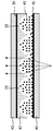
도 2 및 도 3은 도 1에 도시된 상기 디바이스에서 채용될 수 있는 전기적으로 스위칭 가능한 렌티큘러 소자들(35)의 어레이를 개략적으로 도시한다. 상기 어레이는 ITO로 형성된 투명 전극들(43, 45)이 대향하는 면들 상에 제공된 한 쌍의 투명 유리 기판들(39, 41)을 포함한다. 복제 기술을 사용하여 형성된, 역방향 렌즈 구조(47)는 상기 기판들(39) 중 상부에 인접한 기판들(39, 41) 사이에 제공된다. 액정 재료(49)는 또한 상기 기판들(41) 중 하부에 인접한 상기 기판들(39, 41) 사이에 제공된다.2 and 3 schematically illustrate an array of electrically switchable
상기 역방향 렌즈 구조(47)는 상기 액정 재료(49)로 하여금 도 2 및 도 3의 단면도에 도시된 바와 같이, 상기 역방향 렌즈 구조(47)와 상기 하부 기판(41) 사이에 평행하고, 긴 렌티큘러 형상을 가정하도록 한다. 상기 액정 재료들과 접하는 상기 하부 기판(41)과 상기 역방향 렌즈 구조(47)의 표면들은 또한 상기 액정 재료를 배향하기 위해 배향층(도시되지 않음)이 제공된다.The
도 2는 어떠한 전위도 상기 전극들(43, 45)에 인가되지 않을 때 상기 어레이를 도시한다. 이 상태에서, 특정 편광의 광에 대한 상기 액정 재료(49)의 굴절률은 상기 역방향 렌즈 어레이(47)보다 상당히 크고, 따라서 상기 렌티큘러 형상들은 광 출력 지향 기능, 즉 도시된 바와 같이, 렌즈 동작을 제공한다.2 shows the array when no potential is applied to the
도 3은 약 50 내지 100볼트의 교류 전위가 상기 전극들(43, 45)에 인가될 때 상기 어레이를 도시한다. 이 상태에서, 특정 편광의 광에 대한 상기 액정 재료(49)의 굴절률은 상기 역방향 렌즈 어레이(47)와 동일하여, 도시된 바와 같이, 상기 렌티큘러 형상들의 상기 광 출력 지향 기능이 소거된다. 따라서, 이 상태에서, 상기 어레이는 "통과" 모드에서 효과적으로 동작한다.3 shows the array when an alternating potential of about 50 to 100 volts is applied to the
당업자는 상기 액정 재료가 특정 편광의 광에만 적용하는 굴절률 스위칭과 함께 복굴절하기 때문에 광 편광 수단이 상기된 어레이와 함께 사용되어야 한다는 것을 이해한다. 상기 광 편광 수단은 상기 디바이스의 상기 디스플레이 패널 또는 상기 이미징 장치의 일부로서 제공될 수 있다.Those skilled in the art understand that optical polarization means should be used with the arrays described above because the liquid crystal material is birefringent with refractive index switching applied only to light of a particular polarization. The optical polarization means can be provided as part of the display panel or the imaging device of the device.
도 1에 도시된 상기 디스플레이 디바이스에 사용하기에 적합한 스위칭 가능한 렌티큘러 소자들의 어레이들의 구조 및 동작의 더 상세한 설명은 미국 특허 6,069,650호에서 발견할 수 있다.A more detailed description of the structure and operation of arrays of switchable lenticular elements suitable for use in the display device shown in FIG. 1 can be found in US Pat. No. 6,069,650.
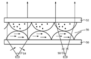
도 4는 상기된 바와 같이 렌티큘러 형 이미징 장치의 동작 원리를 도시하고 백라이트(50), LCD와 같은 디스플레이 디바이스(54) 및 렌티큘러 어레이(58)를 도시한다. 도 4는 상기 렌티큘러 장치(58)가 상이한 픽셀 출력들을 상이한 공간적 위치들로 지향시키는 방법을 도시한다.4 shows the principle of operation of the lenticular imaging apparatus as described above and shows a
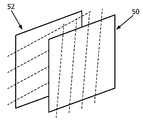
도 5는 다중-뷰 자동입체 디스플레이를 위한 본 발명의 이미징 장치의 제 1 예를 도시한다.5 shows a first example of the imaging device of the present invention for a multi-view autostereoscopic display.
상기 이미징 장치는 제 1(50) 및 제 2(52) 편광-센서티브 렌티큘러 어레이들을 포함한다. 이들은 원하는 방향으로 선택되는 광학 축을 갖는 복굴절 재료로부터 형성된다. 상기 이미징 장치 상의 입사광은 두 개의 가능한 편광들 중에서 하나를 갖도록 제어가능하다. The imaging device includes first 50 and second 52 polarization-sensitive lenticular arrays. They are formed from birefringent materials having an optical axis selected in the desired direction. The incident light on the imaging device is controllable to have one of two possible polarizations.
광선들(54)은 상기 디스플레이의 행 방향으로 편광되는 상기 디스플레이의 픽셀로부터의 광을 나타낸다. 상기 제1 렌티큘러 장치(50)는 동일한 행 방향으로 광학 축을 가져, 이상 굴절률이 상기 인입하는 광에 대한 굴절률을 압도한다(상기 LC 재료의 분자 정렬 축은 일반적으로 상기 이상 굴절률의 축과 동일 선 상에 있다). 상기 렌티큘러 어레이들 간의 재료(56)는 상기 렌티큘러 어레이들의 정상 굴절률에 대응하는 등방성 굴절률을 갖는다. 따라서, 렌즈 기능은 상기 재료(54)와 상기 제 1 어레이의 렌즈들 간의 굴절률 경계에서 구현된다.
상기 제 2 렌티큘러 장치(52)는 상기 열 방향으로 광학 축을 가져, 상기 정상 굴절률은 인입하는 광에 대한 상기 굴절률을 압도한다. 따라서, 통과 모드는 상기 제 2 렌티큘러 어레이(52)에 의해 구현된다.The second
상기 광선(58)은 상기 디스플레이의 열 방향으로 편광된 상기 디스플레이의 픽셀로부터의 광을 나타낸다. 상기 제 1 렌티큘러 장치(50)에 대해, 정상 굴절률이 상기 인입하는 광에 대한 굴절률을 압도하여, 상기 렌즈 표면에 렌즈 기능이 없다. 렌즈 기능은 상기 이상 굴절률이 상기 인입하는 광에 대한 굴절률을 압도하기 때문에, 상기 재료(54)와 상기 제 2 어레이(52)의 렌즈들 간의 굴절률 경계에서 구현된다. The light rays 58 represent light from pixels of the display polarized in the column direction of the display. For the first
두 렌티큘러 어레이들의 재료의 광학 축들은 이미지/디스플레이 패널의 평면에 있지만, 90도 떨어져 있다. 따라서, 상기 디스플레이 출력에 필요한 두 개의 상이한 편광들은 상기 디스플레이에 대해 대략 정상인 서로에 대해 90도로 회전된다.The optical axes of the material of the two lenticular arrays are in the plane of the image / display panel but are 90 degrees apart. Thus, the two different polarizations required for the display output are rotated 90 degrees with respect to each other which is approximately normal for the display.
본 발명은 두 3D 모드들의 선택을 인에이블하기 위해 상기 디스플레이의 출력의 편광을 사용한다. 이들 3D 모드들은 상기 렌티큘러 어레이들의 어떠한 스위칭 기능도 필요로 하지 않고 구현될 수 있다. 이는 정렬층들에 의해 정렬된 광학 축들과 함께 복굴절 성분으로서 구현될 수 있다.The present invention uses the polarization of the output of the display to enable the selection of two 3D modes. These 3D modes can be implemented without requiring any switching function of the lenticular arrays. This can be implemented as a birefringent component with optical axes aligned by alignment layers.
상기 두 3D 모드들은 상기 해상도를 증가(예를 들어 픽셀-간 위치에 뷰들을 추가함으로써) 또는 시간 순차적인 방식으로 뷰들의 수를 증가시키기 위해 사용될 수 있다. 이는 상기 다중 뷰 3D 이미지들의 발생에 의한 성능의 손실이 감소되도록 한다. 그러나, 상기 해상도 개선을 의도하지 않지만 부가적인 기능들이 제공된, 부가적인 출력 기능들이 대신 제공될 수 있다. The two 3D modes can be used to increase the resolution (eg by adding views to an inter-pixel location) or to increase the number of views in a time sequential manner. This allows the loss of performance due to the generation of the multi-view 3D images to be reduced. However, additional output functions may be provided instead, which are not intended to improve the resolution but are provided with additional functions.
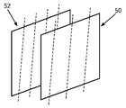
도 5의 제 1 예는 상기 두 개의 렌티큘러 어레이들 간의 작은 상대 이동을 도시한다. 상기 제 1 및 제 2 편광-센서티브 렌티큘러 어레이들(50, 52)은 동일한 렌즈 피치를 갖지만, 하나의 렌티큘러 어레이의 효율적인 렌즈 위치는 상기 픽셀 소자들 간의 피치의 비-정수배인 양만큼 서로에 대해 측면으로 이동된다. 이는 픽셀-간 위치들에서 부가적인 뷰를 제공하여, 출력에서 해상도를 증가시킨다. 상기 이동량은 상기 픽셀 소자들 간의 피치의 절반을 포함할 수 있고, 이는 상기 렌즈가 많은 픽셀(예를 들어, 9)을 커버하면 상기 렌즈 폭에 비해 비교적 적은 이동이다. 그러나, 상기 이동은 도 6에 도시된 바와 같이 상기 렌즈 소자들 간의 피치의 절반을 포함할 수 있다. 상기 렌즈 소자들이 홀수개의 픽셀들을 포함하면, 이는 다시 1/2 픽셀 소자를 포함하는 픽셀 이동을 제공하여, 중간 뷰 위치들이 형성되게 한다. The first example of FIG. 5 shows a small relative movement between the two lenticular arrays. The first and second polarization-sensitive
상기한 바와 같이, 상기 렌티큘러 어레이들은 상기 수직에 대해 기울어지게 된다.As noted above, the lenticular arrays are tilted with respect to the vertical.
예로서, 도 7은 9-뷰 디스플레이의 서브-픽셀 레이아웃을 도시하고 이는 기울어진 렌티큘러 렌즈들(76)을 사용한다. 상기 열들은 차례대로 서브 픽셀들의 적색, 녹색 및 청색 열들로 배열되고, 각각 70, 72, 74와 같은 숫자로 표기되고, 3개의 위에 놓은 렌티큘러 렌즈들(76)이 도시된다. 각각의 렌즈는 4.5 서브-픽셀들의 폭을 갖는다. 도시된 숫자는 상기 서브-픽셀들이 상기 렌즈 축을 따라 -4에서부터 +4까지의 숫자들의 뷰, 뷰 0와 함께 구성된 뷰 번호를 참조한다. 상기 서브-픽셀들의 애스팩트 비가 본 예에서와 같이 1:3일 때(각 픽셀은 3개의 서브-픽셀들의 행을 포함한다) 최적의 기울기 각은 tan(θ)=1/6이다. 결과적으로, 상기 뷰 당 인식된 해상도 손실(2D 경우에 비해)은 상기 기울기 각이 0일 때 수평 방향에서 9의 인자 대신 수평 및 수직 방향에서 3의 인자이다. 상기 블랙 매트릭스로부터 기인하는 다크 밴드의 발생 또한 크게 억제된다.As an example, FIG. 7 shows the sub-pixel layout of a 9-view display, which uses tilted
특정한 뷰에서 특정한 컬러의 서브-픽셀들의 위치들은 오히려 더 멀리 떨어져 분리된다. 이는 규칙적인 2D 디스플레이의 해상도에 비해 해상도 손실로서 인식된다. 예로서, 도 7에서, 뷰 0를 구성하는 녹색 서브-픽셀들의 위치는 빗금친(hatched) 사각형들로 도시된다. The positions of the sub-pixels of a particular color in a particular view are separated farther apart. This is perceived as a resolution loss compared to the resolution of regular 2D displays. As an example, in FIG. 7, the positions of the green sub-pixels that make up view 0 are shown by hatched rectangles.
상이한 위치들에서 렌티큘러들 사이에서 상기 LCD에 대해 시간-순차적인 방식으로 선택함으로써, 상기 빗금친 서브-픽셀들 간의 빈 공간들이 채워진다.By selecting in a time-sequential manner for the LCD between the lenticulars at different locations, the empty spaces between the hatched sub-pixels are filled.
본 발명의 디바이스의 상기 제 1 및 제 2 편광-센서티브 렌티큘러 어레이들은 각각 상기 디스플레이 패널의 열 방향으로부터 장축 오프셋을 갖는 긴 렌티큘러 렌즈들을 포함한다.The first and second polarization-sensitive lenticular arrays of the device of the invention each comprise elongate lenticular lenses having a long axis offset from the column direction of the display panel.
일 실시예에서, 하나의 렌티큘러 어레이에 대한 상기 장축 오프셋은 상기 다른 렌티큘러 어레이의 장축 오프셋과 상이하다. 이는 예를 들어, 이미지 콘텐트에 따라, 두 개의 렌티큘러 어레이들에 의해 획득되는 상이한 뷰잉 효과를 가능하게 한다. 따라서, 상기 행 및 열 방향 사이의 해상도 차이의 바람직한 공유는 이미지의 상이한 유형들에 대해 상이할 수 있다.In one embodiment, the major axis offset for one lenticular array is different than the major axis offset of the other lenticular array. This enables for example different viewing effects obtained by two lenticular arrays, depending on the image content. Thus, the desired sharing of the resolution difference between the row and column directions can be different for different types of images.
도 8에 도시된 예에서, 하나의 렌티큘러 어레이(50)의 장축(점선으로 도시된)은 상기 열 방향으로부터 40도 미만만큼 오프셋되고 상기 다른 렌티큘러 어레이(52)의 장축은 상기 행 방향으로부터 40도 미만만큼 오프셋된다. 이는 각 모드에 대해 사용될 3D 모드들 중 하나로 상기 디스플레이가 인물 및 풍경 모드들 간의 회전이 가능하도록 한다. 상기 선택된 각은 상이한 배향에 대해 최적화되고, 이는 동일한 각이 아니다. 예를 들어, 상기 인물 모드는 각도 tanα=2/3(α는 규정되는 방법에 따라 행 또는 열일 수 있는-수직에 대한 각이다)를 갖는다. 상기 풍경 모드는 각도 tanα=1/3 또는 1/6(α는 다시 규정되는 방법에 따라 행 또는 열일 수 있는-수직에 대한 각이다)를 갖는다. 따라서, 상기 렌즈들은 상기 풍경 모드보다 상기 인물 모드에 대해 더 기울어진다.In the example shown in FIG. 8, the long axis (shown in dashed lines) of one
도 9의 예에서, 상기 제 1 및 제 2 편광-센서티브 렌티큘러 어레이들(50, 52)은 상이한 렌즈 피치(상기 렌즈들의 중심 축은 다시 점선으로 도시된다)를 갖는다. 예를 들어, 3D 모드는 뷰들의 제 1 수일 수 있고 다른 3D 모드는 뷰들의 상이한 수이다. 이는 상기 시스템에 대해 부가적인 유연성을 제공한다. 예를 들어, 상기 디스플레이는 9 뷰 도는 15 뷰 이미지들을 처리할 수 있다.In the example of FIG. 9, the first and second polarization-sensitive
상기한 바와 같이, 상기 렌티큘러 어레이는 3D 모드들 간의 스위칭을 구현하도록 스위칭될 필요는 없다. 그러나, 하나 또는 두 편광-센서티브 렌티큘러 어레이는 각각의 3D 모드 및 2D 모드 간에 전기적으로 스위칭 가능하다. 이는 두 3D 모드들뿐만 아니라 2D 모드를 제공한다. 이는 도 2 및 도 3을 참조하여 설명된 바와 같이, 상기 렌티큘러 어레이들의 복굴절 재료로서 LC 재료를 사용하는 공지의 방법으로 구현될 수 있다. 하나의 렌티큘러 어레이만이 전기적으로 스위칭 가능할 수 있어 광학 축들은 다른 렌티큘러 어레이와 동일하게 스위칭될 수 있고, 하나의 편광의 광은 두 렌티큘러 어레이들 및 중간층(56)의 동일한 굴절률을 보게 된다. As noted above, the lenticular array need not be switched to implement switching between 3D modes. However, one or two polarization-sensitive lenticular arrays are electrically switchable between each 3D mode and 2D mode. It provides two 3D modes as well as a 2D mode. This can be implemented in a known manner using LC material as the birefringent material of the lenticular arrays, as described with reference to FIGS. 2 and 3. Only one lenticular array can be electrically switchable so that the optical axes can be switched to be the same as the other lenticular arrays, and one polarized light sees the same refractive index of both lenticular arrays and the
본 발명은 원하는 편광을 갖는 디스플레이된 이미지의 제어를 필요로 한다.The present invention requires control of the displayed image with the desired polarization.
도 10에 도시된 바와 같이, 이는 디스플레이 패널(5) 및 이미징 장치(9)에 제공된 편광 회전 디바이스(60)에 의해 구현될 수 있다.As shown in FIG. 10, this can be implemented by the
상기 편광 회전 디바이스(60)는 상기 디스플레이 패널 출력의 제어와 동기하여 제어기(62)에 의해 제어된다. 예를 들어, 해상도를 증가시키기 위해, 순차적인 이미지들이 상기 3D 모드들 간의 교대와 함께 100MHz에서 디스플레이될 수 있고, 또는 상기 디스플레이가 주어진 모드(즉, 풍경 또는 인물, 또는 특정 수의 뷰들에 대한 모드)에 있으면 다른 한 3D 모드가 영구적으로 선택될 수 있다.The
상기 편광 회전 디바이스는 상기 디스플레이에 대해 법선에 관해, 90도만큼 (선형) 편광 회전을 위한 것이다. 이는 예를 들어 트위스티드 네마틱 셀에 의해 구현될 수 있다.The polarization rotation device is for (linear) polarization rotation by 90 degrees with respect to the normal to the display. This may be implemented for example by twisted nematic cells.
상기한 예들은 상기 두 렌티큘러 어레이들이 상기 디스플레이 픽셀들에 대해 상이한 기울기 각, 피치, 기울기 배향 또는 위치를 가질 수 있다는 것을 도시한다. 상기 렌즈 형상들은 또한 상이한 뷰잉 효과들을 제공하기 위해 상이할 수 있다.The above examples show that the two lenticular arrays may have different tilt angles, pitches, tilt orientations or positions with respect to the display pixels. The lens shapes can also be different to provide different viewing effects.
각각의 렌티큘러 렌즈 소자는 다중-뷰 시스템을 제공하기 위해, 다수의 픽셀들을 커버한다. 바람직하게, 각각의 렌즈의 폭은 상기 디스플레이의 4개의 픽셀들(또는 서브-픽셀들)에 대해 적어도 동일하다. 상기 감소될 해상도 손실은 특히 다중-뷰 디스플레이들에 대해 중요하다. 상기 다중-뷰 디스플레이는 바람직하게 적어도 3개의 자동입체 뷰들을 제공한다(이 경우 적어도 4개의 상이한 개별 뷰들이 필요하다). 이들은 상기 디스플레이 출력에서 인접한 뷰잉 콘들에서 전형적으로 반복된다. 더 바람직하게, 상기 다중-뷰 디스플레이는 4 이상의 자동입체 뷰들을 제공할 수 있다.Each lenticular lens element covers multiple pixels to provide a multi-view system. Preferably, the width of each lens is at least the same for the four pixels (or sub-pixels) of the display. The resolution loss to be reduced is particularly important for multi-view displays. The multi-view display preferably provides at least three autostereoscopic views (in which case at least four different individual views are required). These are typically repeated at adjacent viewing cones in the display output. More preferably, the multi-view display can provide four or more autostereoscopic views.
상기된 예들은 예를 들어, 50㎛ 내지 1000㎛의 범위의 디스플레이 픽셀 피치를 갖는 액정 디스플레이 패널을 채용한다. 그러나, 당업자는 디스플레이 패널의 대안적인 유형들은 OLED(organic light emitting diode) 또는 CRT(cathode ray tube) 디스플레이 디바이스와 같이, 출력 편광을 제공하기 위해 편광기와 함께 채용된다는 것을 이해할 것이다.The above examples employ, for example, a liquid crystal display panel having a display pixel pitch in the range of 50 μm to 1000 μm. However, those skilled in the art will understand that alternative types of display panels are employed with polarizers to provide output polarization, such as organic light emitting diode (OLED) or cathode ray tube (CRT) display devices.
당업자에게 관습적이고 공지된 상기 디스플레이 디바이스를 제조하기 위한 제조자 및 재료들은 상세하게 설명되지 않았다.Manufacturers and materials for making such display devices customary and known to those skilled in the art have not been described in detail.
개시된 실시예들에 대한 다른 변경들이 도면들, 명세서, 및 청구항들을 연구함으로써 청구된 발명을 실시하는데 있어서 당업자에게 이해되고 실시된다. 청구항들에서, 용어 "포함하는"은 다른 소자들 또는 단계들을 배제하지 않는다, 부정관사 "a" 또는 "an"은 복수를 배제하지 않는다. 단일 프로세서 또는 다른 유닛이 상기 방법 단계들을 충족할 수 있다. 특정 수단들이 상호 다른 종속항들에 언급되는 단순한 사실이 이들 수단들의 조합이 유리하게 사용되지 않는다는 것을 나타내지 않는다. 상기 방법을 구현하기 위한 컴퓨터 프로그램은 광학 저장 매체 또는 하드웨어와 함께 또는 다른 하드웨어의 부품으로서 고상 매체와 같은 적절한 매체 상에 저장/분배될 수 있지만, 인터넷 또는 다른 유선 또는 무선 통신 시스템들을 통해서와 같이 다른 형태로 분배될 수 있다. 청구항의 임의의 참조 번호들은 범위를 한정하는 것으로 해석되어선 안 된다.Other changes to the disclosed embodiments are understood and practiced by those skilled in the art in practicing the claimed invention by studying the drawings, specification, and claims. In the claims, the term comprising does not exclude other elements or steps, the indefinite article "a" or "an" does not exclude a plurality. A single processor or other unit may fulfill the method steps. The simple fact that certain means are mentioned in mutually dependent claims does not indicate that a combination of these means is not advantageously used. The computer program for implementing the method may be stored / distributed on an appropriate medium, such as a solid state medium, together with optical storage medium or hardware or as part of other hardware, but other such as via the Internet or other wired or wireless communication systems. It can be dispensed in the form. Any reference signs in the claims should not be construed as limiting the scope.
Claims (15)
- 디스플레이를 생성하기 위한 디스플레이 픽셀 소자들(5)의 어레이를 갖는 디스플레이 패널(3)로서, 상기 디스플레이 픽셀 소자들은 행 및 열로 배열되는, 상기 디스플레이 패널(3); 및
- 상이한 위치에서 보게 되는 복수의 입체 이미지들을 인에이블하도록 상이한 픽셀 소자들로부터의 출력을 상이한 공간적 위치들로 향하게 하는 이미징 장치(9)를 포함하고,
상기 이미징 장치는 제 1 편광-센서티브 렌티큘러 어레이(50; polarization-sensitive lenticular array) 및 제 2 편광-센서티브 렌티큘러 어레이(52)를 포함하고, 상기 이미징 장치 상의 입사광은 두 개의 가능한 편광들 중 하나를 갖도록 제어가능하고, 상기 두 개의 가능한 편광들 각각은 적어도 제 1 및 제 2 3D 모드들 중 하나를 제공하는, 적어도 제 1 및 제 2 3D 모드를 제공하기 위한 다중-뷰 자동입체 디스플레이 디바이스.A multi-view autostereoscopic display device for providing at least a first and a second 3D mode, comprising:
A display panel (3) having an array of display pixel elements (5) for producing a display, wherein the display pixel elements are arranged in rows and columns; And
An imaging device 9 for directing output from different pixel elements to different spatial locations to enable a plurality of stereoscopic images viewed at different locations,
The imaging device includes a first polarization-sensitive lenticular array 50 and a second polarization-sensitive lenticular array 52, wherein the incident light on the imaging device has one of two possible polarizations. A multi-view autostereoscopic display device for providing at least first and second 3D modes, wherein the controllable, each of the two possible polarizations provides at least one of the first and second 3D modes.
상기 이미징 장치(9) 상의 상기 입사광의 편광을 제어할 수 있는 편광 회전 디바이스(60)를 더 포함하는, 적어도 제 1 및 제 2 3D 모드를 제공하기 위한 다중-뷰 자동입체 디스플레이 디바이스.The method of claim 1,
A multi-view autostereoscopic display device for providing at least first and second 3D modes, further comprising a polarization rotating device (60) capable of controlling the polarization of the incident light on the imaging device (9).
상기 이미징 장치(9) 상의 상기 입사광의 제 1 편광에 대하여, 상기 제 1 편광-센서티브 렌티큘러 어레이(50)는 통과 모드에서 동작하고 상기 제 2 편광-센서티브 렌티큘러 어레이(52)는 렌즈 모드(lensing mode)에서 동작하고, 상기 이미징 장치(9) 상의 상기 입사광의 제 2 편광에 대하여, 상기 제 1 편광-센서티브 렌티큘러 어레이(50)는 렌즈 모드에서 동작하고 상기 제 2 편광-센서티브 렌티큘러 어레이(52)는 통과 모드에서 동작하는, 적어도 제 1 및 제 2 3D 모드를 제공하기 위한 다중-뷰 자동입체 디스플레이 디바이스.The method of claim 1,
For the first polarization of the incident light on the imaging device 9, the first polarization-sensitive lenticular array 50 operates in a pass mode and the second polarization-sensitive lenticular array 52 is in a lens mode. ) And for the second polarization of the incident light on the imaging device 9, the first polarization-sensitive lenticular array 50 operates in lens mode and the second polarization-sensitive lenticular array 52 is A multi-view autostereoscopic display device for providing at least a first and a second 3D mode operating in a pass-through mode.
상기 제 1 및 제 2 편광-센서티브 렌티큘러 어레이(50, 52)는 상이한 렌즈 피치를 갖는, 적어도 제 1 및 제 2 3D 모드를 제공하기 위한 다중-뷰 자동입체 디스플레이 디바이스.The method of claim 1,
Wherein the first and second polarization-sensitive lenticular arrays (50, 52) have different lens pitches, to provide at least first and second 3D modes.
하나의 3D 모드는 제 1 수의 뷰들에 대한 것이고 다른 3D 모드는 상이한 수의 뷰들에 대한 것인, 적어도 제 1 및 제 2 3D 모드를 제공하기 위한 다중-뷰 자동입체 디스플레이 디바이스.The method of claim 4, wherein
One-D auto-stereoscopic display device for providing at least a first and second 3D mode, wherein one 3D mode is for a first number of views and the other 3D mode is for a different number of views.
상기 제 1 뷰들의 수는 9이고 제 2 뷰들의 수는 15인, 적어도 제 1 및 제 2 3D 모드를 제공하기 위한 다중-뷰 자동입체 디스플레이 디바이스.The method of claim 5, wherein
Wherein the number of the first views is nine and the number of the second views is fifteen.
각각의 편광-센서티브 렌티큘러 어레이(50, 52)는 각각의 3D 모드와 2D 모드 사이에서 전기적으로 스위칭 가능한, 적어도 제 1 및 제 2 3D 모드를 제공하기 위한 다중-뷰 자동입체 디스플레이 디바이스.The method of claim 1,
Each polarization-sensitive lenticular array (50, 52) is electrically switchable between each 3D mode and 2D mode, to provide at least first and second 3D modes.
상기 제 1 및 제 2 편광-센서티브 렌티큘러 어레이(50, 52)는 동일한 렌즈 피치를 갖고, 하나의 렌티큘러 어레이의 효과적인 렌즈 위치는 상기 픽셀 소자들 간의 피치의 비-정수 배인 양만큼 다른 렌티큘러 어레이에 대해 측방향으로 이동되는, 적어도 제 1 및 제 2 3D 모드를 제공하기 위한 다중-뷰 자동입체 디스플레이 디바이스.The method of claim 1,
The first and second polarization-sensitive lenticular arrays 50, 52 have the same lens pitch, and the effective lens position of one lenticular array is relative to the other lenticular array by an amount that is a non-integer multiple of the pitch between the pixel elements. A multi-view autostereoscopic display device for providing laterally moved at least first and second 3D modes.
상기 이동량은 상기 픽셀 소자들 간의 피치의 1/2을 포함하는, 적어도 제 1 및 제 2 3D 모드를 제공하기 위한 다중-뷰 자동입체 디스플레이 디바이스.The method of claim 8,
And the movement amount comprises one-half of the pitch between the pixel elements, to provide at least a first and a second 3D mode.
상기 이동량은 상기 렌즈 소자들 간의 피치의 1/2을 포함하는, 적어도 제 1 및 제 2 3D 모드를 제공하기 위한 다중-뷰 자동입체 디스플레이 디바이스.The method of claim 8,
And the movement amount comprises one half of the pitch between the lens elements. 10. A multi-view autostereoscopic display device for providing at least a first and a second 3D mode.
상기 제 1 및 제 2 편광-센서티브 렌티큘러 어레이(50, 52)는 각각 상기 디스플레이 패널의 열 방향으로부터의 장축 오프셋을 갖는, 긴 렌티큘러 렌즈들을 포함하는, 적어도 제 1 및 제 2 3D 모드를 제공하기 위한 다중-뷰 자동입체 디스플레이 디바이스.The method of claim 1,
The first and second polarization-sensitive lenticular arrays 50 and 52 each comprise elongate lenticular lenses, each having a long axis offset from the column direction of the display panel. Multi-View Autostereoscopic Display Device.
하나의 렌티큘러 어레이에 대한 상기 장축 오프셋은 다른 렌티큘러 어레이의 장축 오프셋과는 상이한, 적어도 제 1 및 제 2 3D 모드를 제공하기 위한 다중-뷰 자동입체 디스플레이 디바이스.The method of claim 11,
The multi-view autostereoscopic display device for providing at least first and second 3D modes, wherein the long axis offset for one lenticular array is different from the long axis offset of the other lenticular array.
상기 하나의 렌티큘러 어레이(50)의 장축은 상기 열 방향으로부터 40도 미만으로 오프셋되고 다른 렌티큘러 어레이(52)의 장축은 상기 행 방향으로부터 40도 미만으로 오프셋되는, 적어도 제 1 및 제 2 3D 모드를 제공하기 위한 다중-뷰 자동입체 디스플레이 디바이스.The method of claim 12,
The long axis of the one lenticular array 50 is offset by less than 40 degrees from the column direction and the long axis of the other lenticular array 52 is offset by less than 40 degrees from the row direction by at least the first and second 3D modes. A multi-view autostereoscopic display device for providing.
상기 디스플레이 패널(3)은 개별적으로 어드레싱 가능한 방사성, 전도성, 굴절성 또는 회절성 디스플레이 픽셀들의 어레이를 포함하는, 적어도 제 1 및 제 2 3D 모드를 제공하기 위한 다중-뷰 자동입체 디스플레이 디바이스.The method of claim 1,
The display panel (3) comprises at least a first and second 3D mode, wherein the display panel comprises an array of individually addressable radioactive, conductive, refractive or diffractive display pixels.
상기 자동입체 디스플레이는 디스플레이 패널(3) 및 상기 디스플레이 패널 출력을 보여지는 입체 이미지를 인에이블하도록 상이한 위치들로 향하게 하기 위한 이미징 장치(9)를 포함하고,
상기 방법은:
- 제 1 편광을 갖는 제 1 이미지를 디스플레이하고, 상기 제 1 이미지를 이미징 장치(9)로 제공하여, 이미징 장치는 상이한 위치에서 보게 되는 복수의 입체 이미지들을 인에이블하도록 상이한 픽셀 소자들로부터의 출력을 상이한 공간적 위치들로 향하게 하는 제 1 및 제 2 편광-센서티브 렌티큘러 어레이(50, 52)를 포함하여, 제 1 3D 모드를 제공하는 단계;
- 제 2 편광을 갖는 제 2 이미지를 디스플레이하고, 상기 제 2 이미지를 상기 이미징 장치(9)에 제공하여, 제 2 3D 모드를 제공하는 단계를 포함하는, 적어도 제 1 및 제 2 3D 모드를 제공하기 위한 다중-뷰 자동입체 디스플레이 제어 방법.A multi-view autostereoscopic display control method for providing at least a first and a second 3D mode, the method comprising:
The autostereoscopic display comprises a display panel 3 and an imaging device 9 for directing the display panel output to different positions to enable a stereoscopic image to be viewed,
The method is:
Displaying a first image with a first polarization and providing the first image to the imaging device 9 so that the imaging device outputs from different pixel elements to enable a plurality of stereoscopic images viewed at different locations. Providing a first 3D mode, including first and second polarization-sensitive lenticular arrays (50, 52) for directing to different spatial locations;
Displaying a second image with a second polarization, and providing the second image to the imaging device 9 to provide a second 3D mode, providing at least first and second 3D modes. A method for controlling multi-view autostereoscopic display.
Applications Claiming Priority (2)
| Application Number | Priority Date | Filing Date | Title |
|---|---|---|---|
| EP09163872 | 2009-06-26 | ||
| EP09163872.6 | 2009-06-26 |
Publications (1)
| Publication Number | Publication Date |
|---|---|
| KR20120052236A true KR20120052236A (en) | 2012-05-23 |
Family
ID=42562705
Family Applications (1)
| Application Number | Title | Priority Date | Filing Date |
|---|---|---|---|
| KR1020127001700A KR20120052236A (en) | 2009-06-26 | 2010-06-21 | Multi-view autostereoscopic display device |
Country Status (9)
| Country | Link |
|---|---|
| US (1) | US20120092339A1 (en) |
| EP (1) | EP2446637A1 (en) |
| JP (1) | JP2012531618A (en) |
| KR (1) | KR20120052236A (en) |
| CN (1) | CN102598671B (en) |
| BR (1) | BRPI1010077A2 (en) |
| RU (1) | RU2546553C2 (en) |
| TW (1) | TW201105113A (en) |
| WO (1) | WO2010150174A1 (en) |
Cited By (1)
| Publication number | Priority date | Publication date | Assignee | Title |
|---|---|---|---|---|
| US9588348B2 (en) | 2012-11-12 | 2017-03-07 | Samsung Display Co., Ltd. | 3D display device |
Families Citing this family (26)
| Publication number | Priority date | Publication date | Assignee | Title |
|---|---|---|---|---|
| KR101897479B1 (en) * | 2009-11-03 | 2018-09-12 | 코닌클리케 필립스 엔.브이. | Autostereoscopic display device |
| US10295833B2 (en) * | 2010-12-15 | 2019-05-21 | SoliDDD Corp. | Resolution for autostereoscopic video displays |
| EP2724544B1 (en) * | 2011-06-22 | 2017-02-22 | Koninklijke Philips N.V. | Autostereoscopic display apparatus having optical magnification |
| JP5253563B2 (en) * | 2011-12-09 | 2013-07-31 | 株式会社東芝 | 3D image display device and display method |
| EP2653906B1 (en) | 2012-04-20 | 2022-08-24 | Dolby Laboratories Licensing Corporation | A system for delivering stereoscopic images |
| US9563062B2 (en) * | 2012-09-04 | 2017-02-07 | SoliDDD Corp. | Switchable lenticular array for autostereoscopic video display |
| WO2014064588A2 (en) | 2012-10-26 | 2014-05-01 | Koninklijke Philips N.V. | Autostereoscopic display device having a see-through mode of operation. |
| CN102927473B (en) * | 2012-11-06 | 2016-03-02 | 东南大学 | The lighting device that a kind of beam and focus is controlled |
| TWI472802B (en) * | 2012-11-15 | 2015-02-11 | Au Optronics Corp | Display device |
| US9052518B2 (en) * | 2012-11-30 | 2015-06-09 | Lumenco, Llc | Slant lens interlacing with linearly arranged sets of lenses |
| JP2014115464A (en) * | 2012-12-10 | 2014-06-26 | Dainippon Printing Co Ltd | Display device |
| CN103096109B (en) * | 2013-01-18 | 2015-05-06 | 昆山龙腾光电有限公司 | Multiple view automatic stereoscopic displayer and display method |
| CN103926704A (en) * | 2013-06-09 | 2014-07-16 | 天马微电子股份有限公司 | Lens display device, liquid crystal display device and display drive method |
| JP2016531310A (en) | 2013-07-02 | 2016-10-06 | コーニンクレッカ フィリップス エヌ ヴェKoninklijke Philips N.V. | Autostereoscopic display device |
| US9823482B2 (en) | 2013-08-19 | 2017-11-21 | Universal Display Corporation | Autostereoscopic displays |
| CN104730722A (en) * | 2013-12-18 | 2015-06-24 | 财团法人工业技术研究院 | Time multitask scanning device and 3D display device |
| CN103945203A (en) * | 2013-12-19 | 2014-07-23 | 上海天马微电子有限公司 | Stereo image display device |
| CN104064123B (en) * | 2014-07-05 | 2016-02-24 | 福州大学 | A kind of 3D-LED display system without Moire fringe |
| US10356397B2 (en) | 2015-02-13 | 2019-07-16 | Samsung Electronics Co., Ltd. | Three-dimensional (3D) display apparatus and method |
| US10798367B2 (en) * | 2015-02-27 | 2020-10-06 | Sony Corporation | Imaging device, image processing device and image processing method |
| US9712810B2 (en) | 2015-06-03 | 2017-07-18 | Disney Enterprises, Inc. | Tracked automultiscopic 3D tabletop display |
| US10298921B1 (en) * | 2018-02-27 | 2019-05-21 | Looking Glass Factory, Inc. | Superstereoscopic display with enhanced off-angle separation |
| WO2020222770A1 (en) * | 2019-04-29 | 2020-11-05 | Leia Inc. | Multiview display and method having shifted color sub-pixels |
| CN109870822B (en) * | 2019-04-19 | 2021-01-26 | 京东方科技集团股份有限公司 | Display system, control method thereof and medium |
| CN113359312B (en) * | 2020-03-06 | 2023-09-15 | 驻景(广州)科技有限公司 | Optical waveguide display module based on multiple light sources |
| CN113703176B (en) * | 2021-09-11 | 2023-05-30 | 成都航空职业技术学院 | 3D display device based on gradual change compound slit grating |
Family Cites Families (13)
| Publication number | Priority date | Publication date | Assignee | Title |
|---|---|---|---|---|
| GB9511519D0 (en) * | 1995-06-07 | 1995-08-02 | Richmond Holographic Res | Autostereoscopic display with enlargeable image volume |
| US6064424A (en) * | 1996-02-23 | 2000-05-16 | U.S. Philips Corporation | Autostereoscopic display apparatus |
| GB9623682D0 (en) | 1996-11-14 | 1997-01-08 | Philips Electronics Nv | Autostereoscopic display apparatus |
| JP3969252B2 (en) * | 2002-08-27 | 2007-09-05 | 日本電気株式会社 | Stereoscopic image plane image switching display device and portable terminal device |
| GB2403815A (en) * | 2003-07-10 | 2005-01-12 | Ocuity Ltd | Birefringent lens array structure |
| RU2003125624A (en) * | 2003-08-22 | 2005-02-27 | н Эмин Хачикович Гулан (RU) | DEVICE FOR FORMING A THREE-DIMENSIONAL IMAGE (THREE-DIMENSIONAL STEREOSCOPIC DISPLAY) AND A SYSTEM USING IT |
| KR100813977B1 (en) * | 2005-07-08 | 2008-03-14 | 삼성전자주식회사 | High resolution 2D-3D switchable autostereoscopic display apparatus |
| KR101128519B1 (en) * | 2005-08-04 | 2012-03-27 | 삼성전자주식회사 | High resolution autostereoscopic display |
| JP4095635B2 (en) * | 2005-09-15 | 2008-06-04 | 株式会社東芝 | Stereoscopic image display device |
| DE602006021623D1 (en) * | 2005-12-14 | 2011-06-09 | Koninkl Philips Electronics Nv | CONTROL OF THE TREATED DEPTH OF AN AUTOSTEREOSCOPIC DISPLAY DEVICE AND METHOD THEREFOR |
| CN101341763B (en) * | 2005-12-20 | 2010-12-08 | 皇家飞利浦电子股份有限公司 | Autostereoscopic display device |
| CN100492101C (en) * | 2007-09-29 | 2009-05-27 | 北京超多维科技有限公司 | 2D-3D switching stereo display device |
| JP5022964B2 (en) * | 2008-03-28 | 2012-09-12 | 株式会社東芝 | 3D image display apparatus and 3D image display method |
-
2009
- 2009-06-21 US US13/380,164 patent/US20120092339A1/en not_active Abandoned
-
2010
- 2010-06-21 JP JP2012516928A patent/JP2012531618A/en active Pending
- 2010-06-21 CN CN201080028877.1A patent/CN102598671B/en not_active Expired - Fee Related
- 2010-06-21 WO PCT/IB2010/052794 patent/WO2010150174A1/en active Application Filing
- 2010-06-21 EP EP10730246A patent/EP2446637A1/en not_active Ceased
- 2010-06-21 RU RU2012102589/08A patent/RU2546553C2/en not_active IP Right Cessation
- 2010-06-21 BR BRPI1010077A patent/BRPI1010077A2/en not_active IP Right Cessation
- 2010-06-21 KR KR1020127001700A patent/KR20120052236A/en not_active Application Discontinuation
- 2010-06-23 TW TW099120508A patent/TW201105113A/en unknown
Cited By (1)
| Publication number | Priority date | Publication date | Assignee | Title |
|---|---|---|---|---|
| US9588348B2 (en) | 2012-11-12 | 2017-03-07 | Samsung Display Co., Ltd. | 3D display device |
Also Published As
| Publication number | Publication date |
|---|---|
| RU2546553C2 (en) | 2015-04-10 |
| US20120092339A1 (en) | 2012-04-19 |
| EP2446637A1 (en) | 2012-05-02 |
| RU2012102589A (en) | 2013-08-10 |
| BRPI1010077A2 (en) | 2016-03-15 |
| CN102598671B (en) | 2015-09-30 |
| CN102598671A (en) | 2012-07-18 |
| TW201105113A (en) | 2011-02-01 |
| JP2012531618A (en) | 2012-12-10 |
| WO2010150174A1 (en) | 2010-12-29 |
Similar Documents
| Publication | Publication Date | Title |
|---|---|---|
| RU2546553C2 (en) | Multi-view autostereoscopic display device | |
| EP1967017B1 (en) | Autostereoscopic display device | |
| US8330881B2 (en) | Autostereoscopic display device | |
| US8436953B2 (en) | Stereoscopic display | |
| TWI434067B (en) | Stereo display device and lens array thereof | |
| EP2497274B1 (en) | Autostereoscopic display device | |
| EP3086161B1 (en) | Autostereoscopic display device | |
| KR102261218B1 (en) | Auto-stereoscopic display device with a striped backlight and two lenticular lens arrays | |
| JP2009519487A (en) | Display apparatus and method | |
| JP2010282090A (en) | Stereoscopic image display device | |
| US10462453B2 (en) | Display device and display control method |
Legal Events
| Date | Code | Title | Description |
|---|---|---|---|
| A201 | Request for examination | ||
| E902 | Notification of reason for refusal | ||
| E601 | Decision to refuse application |