KR20120049279A - Vehicle control system - Google Patents
Vehicle control system Download PDFInfo
- Publication number
- KR20120049279A KR20120049279A KR1020127004306A KR20127004306A KR20120049279A KR 20120049279 A KR20120049279 A KR 20120049279A KR 1020127004306 A KR1020127004306 A KR 1020127004306A KR 20127004306 A KR20127004306 A KR 20127004306A KR 20120049279 A KR20120049279 A KR 20120049279A
- Authority
- KR
- South Korea
- Prior art keywords
- indicator
- vehicle
- acceleration
- value
- driving
- Prior art date
Links
Images


Classifications
-
- B—PERFORMING OPERATIONS; TRANSPORTING
- B60—VEHICLES IN GENERAL
- B60W—CONJOINT CONTROL OF VEHICLE SUB-UNITS OF DIFFERENT TYPE OR DIFFERENT FUNCTION; CONTROL SYSTEMS SPECIALLY ADAPTED FOR HYBRID VEHICLES; ROAD VEHICLE DRIVE CONTROL SYSTEMS FOR PURPOSES NOT RELATED TO THE CONTROL OF A PARTICULAR SUB-UNIT
- B60W30/00—Purposes of road vehicle drive control systems not related to the control of a particular sub-unit, e.g. of systems using conjoint control of vehicle sub-units, or advanced driver assistance systems for ensuring comfort, stability and safety or drive control systems for propelling or retarding the vehicle
- B60W30/02—Control of vehicle driving stability
-
- B—PERFORMING OPERATIONS; TRANSPORTING
- B60—VEHICLES IN GENERAL
- B60W—CONJOINT CONTROL OF VEHICLE SUB-UNITS OF DIFFERENT TYPE OR DIFFERENT FUNCTION; CONTROL SYSTEMS SPECIALLY ADAPTED FOR HYBRID VEHICLES; ROAD VEHICLE DRIVE CONTROL SYSTEMS FOR PURPOSES NOT RELATED TO THE CONTROL OF A PARTICULAR SUB-UNIT
- B60W40/00—Estimation or calculation of non-directly measurable driving parameters for road vehicle drive control systems not related to the control of a particular sub unit, e.g. by using mathematical models
- B60W40/08—Estimation or calculation of non-directly measurable driving parameters for road vehicle drive control systems not related to the control of a particular sub unit, e.g. by using mathematical models related to drivers or passengers
- B60W40/09—Driving style or behaviour
Abstract
차량의 주행 상태에 기초하는 지표를 구하고 상기 지표에 따라 상기 차량의 주행 특성을 변화시키는 차량 제어 시스템에 있어서, 상기 차량을 기민하게 주행시키는 (crisp running) 방향으로의 상기 주행 상태의 변화에 응답한 상기 지표에서의 변화를, 상기 차량의 주행의 기민성 (crispness) 을 감소시키는 방향으로의 상기 주행 상태의 변화에 응답한 상기 지표에서의 변화보다 빠르게 하도록 하는 지표 설정 수단이 제공된다.A vehicle control system that obtains an indicator based on a running state of a vehicle and changes the running characteristic of the vehicle according to the indicator, the vehicle control system responsive to a change in the running state in a crisp running direction. Indicator setting means is provided for causing a change in the indicator to be earlier than a change in the indicator in response to a change in the running state in a direction to reduce the crispness of the running of the vehicle.
Description
본 발명은 차량의 동력 특성, 조타 특성, 또는 현가 특성과 같은 차량의 거동 특성 또는 가속/감속 특성 (이하, 주행 특성이라고 함) 을, 이 주행 특성이 주행 환경과 운전자의 기호 및 주행 의도에 부합하도록 제어되게 구성된 차량 제어 시스템에 관한 것이다.According to the present invention, the driving characteristics or acceleration / deceleration characteristics (hereinafter referred to as driving characteristics) of the vehicle such as the power characteristics, steering characteristics, or suspension characteristics of the vehicle correspond to the driving environment and the driver's preference and driving intention. And a vehicle control system configured to be controlled.
차속 및 주행 방향과 같은 차량의 거동은, 운전자의 가속/감속 조작 및 조타 조작에 따라 변화하지만, 그 운전자의 조작량과 거동의 변화량과의 관계는, 연비와 같은 에너지 효율 뿐만 아니라, 차량에 요구되는 승차감, 조용함, 및 동력 성능과 같은 특성에 의해서도 또한 결정된다.The behavior of the vehicle, such as the vehicle speed and the direction of travel, changes depending on the driver's acceleration / deceleration and steering operations. It is also determined by characteristics such as ride comfort, quietness, and power performance.
한편, 차량이 주행하는 환경은, 시가지나 고속도로, 곡선도로, 오르막 및 내리막과 같은 여러 환경 또는 도로 유형을 포함하며, 운전자의 기호 및 주행 의도도 다양하며, 주행 중에 운전자가 차량에서 받는 인상도 다양하다. 따라서, 주행 환경이 변화하고 차량이 다른 운전자에 의해 주행되는 경우 예상된 주행 특성이 반드시 얻어지는 것은 아니다. 그 결과, 이른바 운전 특성이 열화할 수도 있다.On the other hand, the environment in which the vehicle travels includes various environments or road types, such as a city street, a highway, a curved road, an uphill road and a downhill road, various driver's preferences and driving intentions, and various impressions the driver receives from the vehicle while driving. Do. Therefore, the expected driving characteristics are not necessarily obtained when the driving environment changes and the vehicle is driven by another driver. As a result, so-called driving characteristics may deteriorate.
따라서, 동력 특성 (또는 가속 성능) 및 현가 특성과 같은 차량의 거동에 관한 주행 특성을, 모드 선택 스위치를 조작하여 수동으로 선택하도록 구성된 유형의 차량이 개발되고 있다. 즉, 이 차량은 예를 들어, 가속 능력이 우수하고, 또한 현가을 약간 딱딱하게 설정하는 스포티-모드, 차량이 비교적으로 낮은 레이트로 가속을 실시하고 비교적 소프트한 현가 특성을 갖는 노멀-모드, 연비 또는 경제성을 우선시 하는 에코-모드로부터 운전 모드를 스위치 조작에 의해 수동 선택하도록 구성된다.Accordingly, vehicles of a type configured to manually select driving characteristics relating to the behavior of the vehicle such as power characteristics (or acceleration performance) and suspension characteristics have been operated by operating a mode selection switch. That is, the vehicle has, for example, a sporty-mode which has excellent acceleration capability and also sets the suspension slightly rigidly, a normal-mode, fuel economy in which the vehicle accelerates at a relatively low rate and has a relatively soft suspension characteristic. Or manually select the operation mode from the eco-mode which prioritizes economy by switch operation.
또한, 운전 지향 (driving orientation) 을 차량의 거동 제어에 반영시키도록 구성된 다양한 시스템이 제안되어 있다. 이 종류의 시스템은 어떠한 스위치 조작도 불필요하고, 정교하고 세밀한 특성의 변경을 허용한다. 이 유형의 시스템의 일례가 일본 특허 출원 공개 번호 제 06-249007 호 (JP-A-06-249007) 에 개시되어 있다. 뉴로컴퓨터를 사용하는 구동력 제어 시스템인 JP-A-06-249007 에서는, 가속 스트로크에 대한 가속도와 차속과의 관계를 요구 가속도 모델로서 학습하여, 그 모델과, 주행과 관련한 운전자의 지향 또는 기호를 반영한 제 2 기준 가속도 모델 사이의 편차, 및 제 2 기준 가속도 모델과 표준 모델로서의 제 1 기준 가속도 모델 사이의 편차에 기초하여 스로틀 개도를 산출하도록 구성된다.In addition, various systems have been proposed that are configured to reflect driving orientation in the behavior control of the vehicle. This type of system does not require any switch operation and allows for the change of precise and detailed characteristics. An example of this type of system is disclosed in Japanese Patent Application Laid-open No. 06-249007 (JP-A-06-249007). In JP-A-06-249007, a driving force control system using a neurocomputer, the relationship between the acceleration and the vehicle speed for the acceleration stroke is learned as a required acceleration model, and the model and the driver's orientation or preferences related to driving are reflected. Throttle opening degree is calculated based on the deviation between the second reference acceleration model and the deviation between the second reference acceleration model and the first reference acceleration model as the standard model.
또, 운전 특성 또는 운전 지향을 차량의 전후 방향과 횡 방향으로 구별하면서 검출하도록 구성된 시스템이 일본 특허 출원 공개 번호 제 11-129924 호 (JP-A-11-129924) 에 개시되어 있다. 이 JP-A-11-129924 에 개시된 시스템은 액셀레이터 페달이나 브레이크 페달의 조작량과 같은 제어 입력 정보, 및 전후 방향 가속도와 같은 거동 정보에 기초하여, 운전자의 가속/제동 모델을 구하고, 또한 조타각과 같은 횡 방향 조작 정보와 요레이트와 같은 횡 방향 거동 정보에 기초하여 운전자의 조타 모델을 구한다.Further, a system configured to detect driving characteristics or driving directions while distinguishing the vehicle from the front-back direction and the lateral direction is disclosed in Japanese Patent Application Laid-Open No. 11-129924 (JP-A-11-129924). The system disclosed in this JP-A-11-129924 calculates a driver's acceleration / braking model based on control input information such as an operation amount of an accelerator pedal or a brake pedal, and behavior information such as forward and backward acceleration, and also obtains a steering angle such as a steering angle. The steering model of the driver is obtained based on the lateral operation information and lateral behavior information such as yaw rate.
JP-A-06-249007 및 JP-A-11-129924 에 개시된 시스템 양쪽 모두는 운전자에 의해 수행된 조작량과 운전자의 조작에 의해 실현된 차량 거동의 변화량 사이의 관계를 검출하도록 구성된다. 이들 시스템과 마찬가지로, 운전자의 조작으로부터 유도되는 운전 조작과 관련된 변수를 이용하여 운전 지향 또는 기호를 추정하도록 구성된 시스템이 일본 특허 출원 공개 번호 제 09-242863 호 (JP-A-09-242863) 에 개시되어 있다. 보다 구체적으로는, JP-A-09-242863에 개시된 시스템은 차량 발진시의 출력 조작량, 출력 조작량의 최대 변화율, 차량의 제동 조작시의 최대 감속도, 차량의 타력 주행 시간, 차속 일정 주행 시간 중 적어도 하나를 수신하는 뉴럴 네트워크 (neural network) 의 출력에 기초하여, 차량의 운전 지향을 추정하도록 구성된다.Both the systems disclosed in JP-A-06-249007 and JP-A-11-129924 are configured to detect a relationship between the amount of manipulation performed by the driver and the amount of change in vehicle behavior realized by the driver's operation. Similar to these systems, a system configured to estimate driving orientation or preference using variables related to driving operation derived from driver's operation is disclosed in Japanese Patent Application Laid-open No. 09-242863 (JP-A-09-242863). It is. More specifically, the system disclosed in JP-A-09-242863 includes at least one of an output operation amount at the time of starting the vehicle, a maximum change rate of the output operation amount, a maximum deceleration rate at the time of braking operation of the vehicle, a traveling time of the vehicle, and a constant driving time of the vehicle speed. Based on the output of the neural network receiving one, it is configured to estimate the driving orientation of the vehicle.
한편, 일본 특허 출원 공개 번호 제 07-156815 호 (JP-A-07-156815) 에는, 운전 지향과 도로 상황을 변속 제어에 의해 반영시키도록 구성된 시스템이 개시되어 있다. 그 운전 지향은, JP-A-07-156815에서는 "기민성 (crispness)" 이라고 표기되어 있으며, 이 기민성은 차속, 액셀레이터 페달 스트로크 및 차량의 전후 가속 및 횡 가속을 포함하는 차량 운전 파라미터들 각각에 대한 빈도수 분포를 구하여, 각 빈도수 분포의 평균치 및 분산을 뉴럴 네트워크 (neural network) 에 입력하여 운전자의 운전 상태를 나타내는 기민성을 추정한다. On the other hand, Japanese Patent Application Laid-Open No. 07-156815 (JP-A-07-156815) discloses a system configured to reflect driving direction and road conditions by shift control. Its driving orientation is referred to in JP-A-07-156815 as "crispness", which is defined for each of the vehicle driving parameters including vehicle speed, accelerator pedal stroke, and forward and backward acceleration and lateral acceleration of the vehicle. The frequency distribution is obtained and the average and the variance of each frequency distribution are input to a neural network to estimate the agility indicative of the driver's driving condition.
차량의 조작량으로서 나타나는 운전자의 의도를 보다 정확하게 반영하는 구동력 제어를 수행하는 것을 목적으로 하는 구동력 제어 시스템이 일본 특허 출원 공개 번호 제 2008-120172 (JP-A-2008-120172) 호에 개시되어 있다. JP-A-2008-120172 에 개시된 시스템은 실제의 차속에 기초한 차속과 운전자의 의도에 기초하여 설정된 목표 차속에 기초하여 차속을 제어하고 횡 가속도에 따라 차속의 제어 방식을 변경하여 그 변경 정도를, 실제의 차속과 목표 차속 사이의 상대 차속에 기초하여 변경하도록 구성된다.A driving force control system is disclosed in Japanese Patent Application Laid-Open No. 2008-120172 (JP-A-2008-120172) for the purpose of performing driving force control that more accurately reflects the driver's intention as a manipulation amount of a vehicle. The system disclosed in JP-A-2008-120172 controls the vehicle speed based on the actual vehicle speed and the target vehicle speed set based on the driver's intention, and changes the control method of the vehicle speed according to the lateral acceleration to change the degree of change. And change based on the relative vehicle speed between the actual vehicle speed and the target vehicle speed.
운전자의 주행 의도를 정확하게 결정하여 운전자의 의도를 반영하는 변속 제어를 수행하도록 구성된 변속 차량 제어 시스템가 일본 특허 출원 공개 번호 제 2004-257434 호 (JP-A-2004-257434) 에 개시되어 있다. JP-A-2004-257434에 개시된 시스템에서는, 차량 가속도의 절대치가 각각의 소정 기간 마다 적분되어 그 적분치가 업데이트된다. 그 적분치가 제 1 기준치보다 큰 경우에는, 제 1 변속 스케쥴이 제 2 변속 스케쥴로 변화되고, 제 1 변속 스케쥴의 적어도 일부에서의 영역에서의 변속 라인들이 고차속 변속 라인으로 변경되어 변속 제어가 제 2 변속 스케쥴에 기초하여 수행된다.A shift vehicle control system configured to accurately determine a driver's driving intention to perform shift control reflecting the driver's intention is disclosed in Japanese Patent Application Laid-open No. 2004-257434 (JP-A-2004-257434). In the system disclosed in JP-A-2004-257434, the absolute value of vehicle acceleration is integrated at each predetermined period so that the integrated value is updated. If the integral value is larger than the first reference value, the first shift schedule is changed to the second shift schedule, and the shift lines in the area in at least a portion of the first shift schedule are changed to the high speed shift line so that the shift control is performed. 2 is performed based on the shift schedule.
또한, 스포티도 (degree of sportiness) 에 따라 변속 제어의 내용을 변경하도록 구성된 시스템이 선행 문헌, 사단법인 자동차 기술회 학술 강연회전쇄집 944 1994-10 (241페이지-244페이지) 에 개시되어 있다. 이 시스템은 도로 구배와 운전의 방식에 따라 차속을 변경하도록 구성되고, 그 운전 방식을 스포티도에 기초하여 결정하도록 구성된다. 이 스포티도는 엔진 부하 또는 타이어 부하도 중 더 큰 값에 기초하여 결정되며, 타이어 부하도는, 타이어의 한계 마찰력에 대한 부하 정도로 나타내어진다.In addition, a system configured to change the content of the shift control in accordance with the degree of sportiness is disclosed in the prior literature, 944 1994-10 (pages 241-244). The system is configured to change the vehicle speed according to the road grade and the manner of driving, and to determine the driving manner based on the sporty degree. This sportiness is determined based on the larger of the engine load or the tire load degree, and the tire load degree is expressed as the degree of load against the limit frictional force of the tire.
상기 서술한 JP-A-06-249007, JP-A-11-129924, JP-A-09-242863, JP-A-07-156815, JP-A-2008-120172, JP-A-2004-257434 및 사단법인 자동차 기술회 학술 강연회전쇄집 944 1994-10 (241페이지-244페이지) 에 개시된 시스템은 운전자 주행 의도를 반영한 제어를 실시하는 것이지만, 이 시스템은 여전히 개선의 여지가 있다.JP-A-06-249007, JP-A-11-129924, JP-A-09-242863, JP-A-07-156815, JP-A-2008-120172, JP-A-2004-257434 And the system disclosed in the Society of Automotive Engineers 944 1994-10 (pages 241 to 244), which implements control that reflects the driver's driving intention, but the system still has room for improvement.
본 발명은 운전자의 기호 및 주행 의도 또는 차량의 주행 상태가 차량의 거동이나 가속와 같은 주행 특성에 정확하게 반영되도록 하는 차량 제어 시스템을 제공하는 것을 목적으로 하는 것이다.It is an object of the present invention to provide a vehicle control system in which a driver's preferences and driving intention or a driving state of a vehicle are accurately reflected in driving characteristics such as behavior or acceleration of the vehicle.
본 발명의 제 1 양상에 따른 차량 제어 시스템은 차량의 주행 상태에 기초하여 지표를 구하고, 상기 지표에 따라 상기 차량의 주행 특성을 변화시키는 차량 제어 시스템으로서, 상기 차량을 기민하게 주행시키는 (crisp running) 방향으로의 상기 주행 상태의 변화에 응답한 상기 지표에서의 변화를, 상기 차량의 주행의 기민성 (crispness) 을 감소시키는 방향으로의 상기 주행 상태의 변화에 응답한 상기 지표에서의 변화보다 빠르게 하도록 하는 지표 설정 수단을 포함한다.A vehicle control system according to a first aspect of the present invention is a vehicle control system that obtains an indicator based on a driving state of a vehicle, and changes a running characteristic of the vehicle according to the indicator, which crisply runs the vehicle. To change the index in response to the change in the driving state in a direction faster than the change in the index in response to the change in the driving state in a direction to reduce the crispness of running of the vehicle. Indicator setting means.
본 발명의 제 1 양상의 차량 제어 시스템에 따르면, 차량의 주행 상태에 기초한 지표는 차량의 주행의 기민성이 증가하는 방향에서는 기민성이 감소되는 방향에서보다 상대적으로 빠르게 변화한다. 그 결과, 차량 제어 시스템에 의해 제어되는 차량은 차량이 주행하는 주행로의 유형과 같은 주행 환경이나 운전 지향에 적합한 주행 특성을 제공한다.According to the vehicle control system of the first aspect of the present invention, the indicator based on the running state of the vehicle changes relatively quickly in the direction in which the agility decreases in the direction in which the agility of the running of the vehicle increases. As a result, the vehicle controlled by the vehicle control system provides a driving characteristic suitable for the driving environment or driving direction, such as the type of driving route on which the vehicle travels.
본 발명의 제 1 양상에 따른 차량 제어 시스템에서는, 상기 지표는, 상기 차량의 주행의 기민성을 증가시키도록 증가될 수 있고, 상기 지표 설정 수단은, 상기 주행 상태가 상기 지표를 증가시키는 방향으로 변화할 때 상기 주행 상태의 변화시 상기 지표를 증가시킬 수 있는 한편, 상기 지표 설정 수단은, 상기 주행 상태가 상기 지표를 감소시키는 방향으로 변화할 때 상기 주행 상태의 변화에 대해 지연되어 상기 지표를 감소시킬 수도 있다.In the vehicle control system according to the first aspect of the present invention, the indicator can be increased to increase the agility of the running of the vehicle, and the indicator setting means changes in the direction in which the driving state increases the indicator. The indicator setting means may be delayed with respect to the change of the driving state when the driving state changes in the direction of decreasing the indicator while reducing the indicator when the driving state changes. You can also
본 발명의 제 1 양상에 따른 차량 제어 시스템에서는, 상기 주행 상태는 상기 차량의 전후 가속도 성분 (longitudinal acceleration component) 과 횡 가속도 성분 (lateral acceleration component) 을 포함하는 합성 가속도를 포함할 수 있으며, 상기 지표 설정 수단은 상기 합성 가속도가 클수록 상기 지표를 큰 값으로 설정할 수도 있다.In the vehicle control system according to the first aspect of the present invention, the driving state may include a synthetic acceleration including a longitudinal acceleration component and a lateral acceleration component of the vehicle, the indicator The setting means may set the index to a larger value as the synthesis acceleration increases.
차량이 주행 중에 전후 가속도 뿐만 아니라 횡 방향과 선회 방향에서의 가속도를 받기 때문에, 본 발명의 제 1 양상에 따른 차량 제어 시스템은 상기 지표가 이들 가속도를 반영하도록 지수를 결정한다. 바꿔 말하면, 상기 지표는 차량의 실제 거동을 개선된 정확도로 반영할 수도 있다.Since the vehicle receives not only forward and backward accelerations but also acceleration in the transverse direction and the turning direction during driving, the vehicle control system according to the first aspect of the present invention determines the index so that the indicator reflects these accelerations. In other words, the indicator may reflect the actual behavior of the vehicle with improved accuracy.
본 발명의 제 1 양상에 따른 차량 제어 시스템에서는, 상기 합성 가속도는 상기 전후 가속도 성분과 상기 횡 가속도 성분을 포함하는 적어도 두개의 방향에서의 가속도 성분들의 절대치를 합성하여 얻은 가속도를 포함할 수도 있다.In the vehicle control system according to the first aspect of the present invention, the synthesized acceleration may include an acceleration obtained by synthesizing an absolute value of acceleration components in at least two directions including the front-back acceleration component and the lateral acceleration component.
본 발명의 제 1 양상에 따른 차량 제어 시스템에서는, 상기 합성 가속도는 복수의 방향들에서의 각각의 가속도 성분들의 자승의 합의 제곱근으로 나타내어지는 가속도를 포함할 수도 있다.In the vehicle control system according to the first aspect of the present invention, the synthesized acceleration may include an acceleration represented by the square root of the sum of the squares of the respective acceleration components in the plurality of directions.
차량의 주행 상태에 기초하여, 상기 차량의 거동에서의 변화 경향으로서 주행 특성을 변화시키는 본 발명의 제 2 양상에 따른 차량 제어 시스템에서는, 상기 차량은 상기 주행 특성을 변경할 수 있는 액추에이터를 포함하고, 상기 차량의 주행 상태는 전후 방향 성분과 횡 방향 성분을 포함하는 상기 경사 방향에서의 가속도를 포함하고, 상기 경사 방향은 수평면 상에서 상기 차량의 전후 방향과 횡 방향으로 대하여 경사져 있다. 상기 차량 제어 시스템은 상기 경사 방향의 가속도에 기초하여 상기 액추에이터의 동작 상태를 변화시킴으로써, 상기 차량의 상기 주행 특성을 변화시키는 특성 변경 수단을 포함한다.In a vehicle control system according to a second aspect of the present invention for changing a running characteristic as a tendency to change in the behavior of the vehicle based on the running state of the vehicle, the vehicle includes an actuator capable of changing the running characteristic, The running state of the vehicle includes acceleration in the inclined direction including a front-rear component and a transverse component, and the inclined direction is inclined with respect to the front-rear direction and the transverse direction of the vehicle on a horizontal plane. The vehicle control system includes characteristic changing means for changing the running characteristic of the vehicle by changing the operating state of the actuator based on the acceleration in the inclination direction.
본 발명의 제 2 양상에 따른 차량 제어 시스템에서는, 액추에이터의 동작 상태가 차량의 복수의 방향들에서의 가속도에 기초하여 변화되어, 상기 주행 특성이 변경된다. 따라서, 차량 제어 시스템은 차량의 실제 거동을 개선된 정확도로 반영하도록 주행 특성을 설정할 수도 있다.In the vehicle control system according to the second aspect of the present invention, the operating state of the actuator is changed based on the acceleration in the plurality of directions of the vehicle, so that the running characteristic is changed. Thus, the vehicle control system may set the driving characteristics to reflect the actual behavior of the vehicle with improved accuracy.
본 발명의 제 3 양상에 따른 차량 제어 시스템은 복수의 방향들에서의 가속도 성분들을 포함하는 가속도에 기초하여, 차량의 거동의 변화 경향으로서 주행 특성을 변화시키는 차량 제어 시스템으로서, 상기 복수의 방향들 중 한 방향에서의 가속도 성분에 기초한 상기 주행 특성의 변화를, 다른 방향의 가속도 성분에 기초하는 상기 주행 특성의 변화와 상이하게 하는 합성 수단 (synthesizing means) 을 포함한다.A vehicle control system according to a third aspect of the present invention is a vehicle control system for changing a driving characteristic as a tendency to change a behavior of a vehicle based on an acceleration including acceleration components in a plurality of directions, the plurality of directions Synthesizing means for varying the change in the running characteristic based on the acceleration component in one of the directions from the change in the running characteristic based on the acceleration component in the other direction.
본 발명의 제 3 양상의 차량 제어 시스템에 따르면, 둘 이상의 방향들에서의 가속도를 반영하도록 차량의 주행 특성이 변화되는 경우, 차량에 실제로 적용된 가속도에 대한 변화와 차량의 거동의 영향은 그 가속도의 방향에 의존하여 변하므로, 이에 따라, 상이함이 주행 특성이 변화될 때 주행 특성에 의해 반영될 수도 있다.According to the vehicle control system of the third aspect of the present invention, when the driving characteristic of the vehicle is changed to reflect the acceleration in two or more directions, the effect of the change on the acceleration actually applied to the vehicle and the behavior of the vehicle is determined by the acceleration of the acceleration. Since it varies depending on the direction, the difference may thus be reflected by the running characteristic when the running characteristic is changed.
본 발명의 제 3 양상의 차량 제어 시스템에서는 상기 복수의 방향들의 가속도 성분들은 상기 차량의 전후 감속 방향의 가속도 (speed-decreasing longitudinal acceleration) 와 차량의 전후 가속 방향의 가속도 (speed-increasing longitudinal acceleration) 를 포함하고, 상기 가속 방향의 가속도의 영향이, 상기 감속 방향의 가속도의 영향 보다 커지도록, 상기 감속 방향의 가속도와 상기 가속 방향의 가속도가 정규화 동작, 가중처리 동작 및 정규화 동작과 가중처리 동작의 조합 중 적어도 하나에 의해 보정된다.In the vehicular control system of the third aspect of the present invention, the acceleration components of the plurality of directions may include speed-decreasing longitudinal acceleration of the vehicle and speed-increasing longitudinal acceleration of the vehicle. And the acceleration in the deceleration direction and the acceleration in the acceleration direction are normalized operation, weighting operation, and combination of normalization operation and weighting operation so that the influence of the acceleration in the acceleration direction is greater than the influence in the acceleration direction. Is corrected by at least one of.
차량의 주행 상태에 기초한 지표에 따라 상기 차량의 주행 특성을 변화시키는 본 발명의 제 4 양상에 따른 차량 제어 시스템으로서, 상기 차량의 주행 개시 후의 시간 동안 경과 시간, 주행 거리, 및 합성 가속도 중 적어도 하나가 증가함에 따라 상기 차량의 주행에서의 기민성이 증가하는 주행 특성을 제공하도록 상기 지표를 변화시키는 지표 변경 수단을 포함한다.A vehicle control system according to a fourth aspect of the present invention for changing a running characteristic of the vehicle in accordance with an indicator based on a running state of a vehicle, the vehicle control system comprising: at least one of an elapsed time, a traveling distance, and a synthetic acceleration during a time after the vehicle starts to travel; And indicator changing means for changing the indicator to provide a driving characteristic in which the agility in driving of the vehicle increases as is increased.
본 발명의 제 4 양상의 차량 제어 시스템에 따르면, 상기 지표가 차량이 주행을 개시한 후 시간의 경과에 의해 증가하거나 또는 상기 지표가 주행거리의 증가로 또는 그 시간 동안의 합성 가속도의 증가로 증가하여, 지표에 따라 주행의 기민성이 향상된다.According to the vehicle control system of the fourth aspect of the present invention, the indicator increases with the passage of time after the vehicle starts to drive, or the indicator increases with an increase in the mileage or with an increase in the combined acceleration during that time. Thus, the agility of the driving is improved according to the indicator.
본 발명의 제 4 양상에 따른 차량 제어 시스템에서는, 상기 지표는 상기 차량의 주행에서의 기민성을 증가시키도록 증가할 수 있고, 상기 지표 변경 수단은 상기 차량의 전후 가속도 성분과 횡 가속도 성분을 포함하는 적어도 두개의 방향에서의 가속도 성분들을 포함하는 합성 가속도가 증가할수록 상기 지표를 보다 큰 값으로 설정할 수도 있다.In the vehicle control system according to the fourth aspect of the present invention, the indicator can be increased to increase agility in driving of the vehicle, and the indicator changing means includes a front and rear acceleration component and a lateral acceleration component of the vehicle. The index may be set to a larger value as the composite acceleration including acceleration components in at least two directions increases.
본 발명의 제 1 양상에 따른 차량 제어 시스템에서는, 상기 지표 설정 수단은 상기 차량의 주행중에 상기 지표를 반복하여 구할 수 있고, 상기 지표 설정 수단은 상기 지표의 구한 값이 전회 값보다 큰 경우 상기 지표를 상기 구한 값으로 유지하는 지표 유지 수단과, 미리 정해진 조건하에서 상기 지표 유지 수단에 의해 유지된 상기 지표의 값을 감소시키는 지표 감소 수단을 포함할 수도 있다. 상기 미리 정해진 조건은 상기 지표가 상기 지표 유지 수단에 의해 유지된 상기 값보다 작게 유지되는 시간 길이에 의존하여 만족될 수도 있다.In the vehicle control system according to the first aspect of the present invention, the indicator setting means may repeatedly obtain the indicator while the vehicle is traveling, and the indicator setting means may determine the indicator when the obtained value of the indicator is larger than the previous value. Indicator holding means for maintaining the value at the obtained value and indicator decreasing means for decreasing the value of the indicator held by the indicator holding means under a predetermined condition. The predetermined condition may be satisfied depending on the length of time that the indicator is kept smaller than the value held by the indicator holding means.
본 발명의 제 1 양상의 차량 제어 시스템에 따르면, 상기 지표가 주행 상태의 변화에 의해 큰 값으로 되면, 상기 지표는 그 큰 값으로 유지되고, 따라서 상기 지표는 현재값보다 큰 값이 얻어질 때마다 업데이트된다. 한편, 주행 상태에 기초하여 구한 지표값이 종전 값보다 작은 경우에도 상기 지표는 시간을 요건으로 한 조건이 만족될 때까지는 종전의 값으로 유지된 다음 상기 조건이 만족될 때 상기 지표가 감소된다. 따라서 지표 및 상기 지표에 기초하는 주행 특성은 이들이 증가되는 경우보다 낮은 레이트에서 또는 감소된 빈도수에서 감소된다.According to the vehicle control system of the first aspect of the present invention, when the indicator becomes a large value due to a change in the driving state, the indicator is kept at that large value, and thus the indicator is obtained when a value larger than the current value is obtained. Is updated every time. On the other hand, even when the indicator value calculated based on the driving condition is smaller than the previous value, the indicator is kept at the previous value until the time requirement is satisfied, and then the indicator is decreased when the condition is satisfied. The indicator and driving characteristics based on the indicator are thus reduced at lower rates or at reduced frequencies than if they were increased.
본 발명의 제 1 양상에 따른 차량 제어 시스템에서는, 상기 조건은 상기 지표의 구한 값과, 상기 지표 유지 수단에 의해 유지되는 상기 지표의 값 간의 편차를 시간에 대하여 적분하여 구한 값이 미리 정해진 값을 초과하는 조건을 포함할 수도 있다.In the vehicle control system according to the first aspect of the present invention, the condition is a value obtained by integrating a deviation between a value obtained from the indicator and a value of the indicator held by the indicator holding means over time. It may also include excess conditions.
본 발명의 제 1 양상의 차량 제어 시스템에 따르면, 지표의 감소를 지연시키기 위해서, 소정의 값으로 유지되는 상기 지표와 매 시점마다 구한 지표 사이의 시간에 대한 편차 또는 차의 적분치가 산출되고, 그 적분치가 미리 정해진 값과 같게 될 때까지 비록 현재 구한 지표의 값이 상대적으로 낮아도, 지표의 값은 상기 소정의 값으로 유지된다. 그 후, 현재 구한 지표값이 상기 소정의 값으로 유지되는 값에 크거나 또는 이 값에 가깝게 되면, 상기 적분치가 리셋되어 지표의 감소가 더욱 지연될 수도 있다.According to the vehicle control system of the first aspect of the present invention, in order to delay the decrease of the indicator, an integral value of the deviation or difference with respect to time between the indicator maintained at a predetermined value and the indicator obtained at each time point is calculated, and Until the integral value becomes equal to a predetermined value, the value of the indicator is kept at the predetermined value even if the value of the currently obtained indicator is relatively low. Thereafter, if the currently obtained index value is larger than or close to the value maintained at the predetermined value, the integral value may be reset to further delay the decrease of the index.
본 발명의 제 1 양상에 따른 차량 제어 시스템에서는, 상기 지표의 구한 값과, 상기 지표 유지 수단에 의해 유지되는 상기 지표의 값 간의 편차의 시간 적분치가 미리 정해진 임계치 이하인 경우, 상기 지표 설정 수단은 상기 편차의 시간 적분치를 리셋할 수도 있고 상기 편차의 시간 적분치를 제로로 되돌릴 수도 있다.In the vehicle control system according to the first aspect of the present invention, when the time integral value of the deviation between the obtained value of the indicator and the value of the indicator held by the indicator holding means is equal to or less than a predetermined threshold, the indicator setting means is configured to perform the above-mentioned operation. The time integral of the deviation may be reset or the time integral of the deviation may be returned to zero.
본 발명의 제 1 양상에 따른 차량 제어 시스템에서는, 상기 지표의 구한 값과, 상기 지표 유지 수단에 의해 유지되는 상기 지표의 값 간의 편차의 시간 적분치가 미리 정해진 임계치 이하인 경우, 상기 지표 감소 수단은 상기 조건의 만족을 지연시킬 수도 있다.In the vehicle control system according to the first aspect of the present invention, when the time integral value of the deviation between the obtained value of the indicator and the value of the indicator held by the indicator holding means is equal to or less than a predetermined threshold, the indicator reducing means is configured to perform the above-mentioned operation. The satisfaction of the condition may be delayed.
본 발명의 제 1 양상에 따른 차량 제어 시스템에서는, 상기 지표 감소 수단은 상기 조건이 만족될 때까지의 경과 시간이 상대적으로 긴 경우에는, 상기 경과 시간이 상대적으로 짧은 경우와 비교해 상기 지표의 값을 감소된 레이트로 감소시킬 수도 있다.In the vehicle control system according to the first aspect of the present invention, when the elapsed time until the condition is satisfied is relatively long, the indicator reducing means compares the value of the indicator with the case where the elapsed time is relatively short. It may be reduced at a reduced rate.
본 발명의 제 1 양상의 차량 제어 시스템에 따르면, 감소의 조건이 만족될 때까지의 시간이 오래 걸린 경우에는, 감소의 조건이 만족될 때까지의 시간이 짧게 걸린 경우와 비교해 보다 낮은 레이트로 지표가 감소되어, 주행 환경이나 주행 의도에 보다 적합한 값으로 지표를 설정할 수도 있다.According to the vehicle control system of the first aspect of the present invention, when it takes a long time until the condition of reduction is satisfied, the indicator is lowered at a lower rate compared with the case where the time until the condition of reduction is shortened. May be reduced, so that the indicator may be set to a value more suitable for the driving environment or the driving intention.
본 발명의 제 1 양상에 따른 차량 제어 시스템에서는, 상기 지표 설정 수단은 상기 조건의 만족이 지연되는 경우, 상기 편차의 시간 적산치 (time accumulated value) 를 감소시킴으로써 상기 편차의 상기 시간 적산치를 구할 수 있다.In the vehicle control system according to the first aspect of the present invention, the indicator setting means can obtain the time integration value of the deviation by reducing the time accumulated value of the deviation when the satisfaction of the condition is delayed. have.
본 발명의 제 1 양상의 차량 제어 시스템에 따르면, 소정의 값으로 유지되는 상기 지표의 값과 상기 지표의 새롭게 구한 값 사이의 차이가 작은 경우에는, 이때의 주행 상태가 지표의 변경의 요인 또는 인자로서 간주되지 못한다. 따라서, 상기 조건이 만족되는 것에 기초하는 경과 시간의 적산이 중단 또는 적산 시간이 감소되어, 주행 특성이 과민하게 변화 (감소) 되는 것을 방지한다.According to the vehicle control system of the first aspect of the present invention, when the difference between the value of the indicator maintained at a predetermined value and the newly obtained value of the indicator is small, the driving state at this time is a factor or factor of the change of the indicator. It is not considered as. Therefore, integration of the elapsed time based on which the above condition is satisfied is stopped or the integration time is reduced, thereby preventing the running characteristic from being changed (reduced) excessively.
본 발명의 제 2 양상에 따른 차량 제어 시스템에서는, 상기 액추에이터는 상기 차량에 탑재된 엔진의 스로틀 개도 (opening) 를 변화시키도록 동작가능한 액추에이터, 상기 차량에 탑재된 자동 변속기의 변속비를 변화시키도록 동작가능한 액추에이터, 상기 차량의 서스펜션 기구에 제공되고 현가 특성을 변화시키도록 동작가능한 액추에이터, 상기 차량의 선회 특성을 변화시키도록 동작가능한 액추에이터, 상기 차량의 전륜과 후륜에 분배된 동력 비율을 변화시키도록 동작가능한 액추에이터 중 적어도 하나를 포함할 수도 있다.In a vehicle control system according to a second aspect of the present invention, the actuator is operable to change a throttle opening of an engine mounted on the vehicle, and is operable to change a transmission ratio of an automatic transmission mounted on the vehicle. Possible actuators, actuators provided to the suspension mechanism of the vehicle and operable to change the suspension characteristics, actuators operable to change the swing characteristics of the vehicle, operable to vary the ratio of power distributed to the front and rear wheels of the vehicle It may also include at least one of the possible actuators.
본 발명의 제 2 양상의 차량 제어 시스템에 따르면, 차량의 가속 성능, 선회 특성, 진동 댐핑 특성 (vibration damping characteristic) 에 관련된 액추에이터의 특성이 주행 환경 또는 운전 지향에 적합하게 이루어질 수도 있다.According to the vehicle control system of the second aspect of the present invention, the characteristics of the actuator related to the acceleration performance, the turning characteristic, the vibration damping characteristic of the vehicle may be made suitable for the driving environment or the driving orientation.
본 발명의 제 1 양상에 따른 차량 제어 시스템에서는, 상기 차량은 구동원 및, 상기 구동원의 회전수를 제어하는 회전수 제어 기구를 포함할 수 있고, 상기 차량 제어 시스템은, 상기 구동원의 목표 회전수를 상기 지표에 기초하여 결정하는 스포티-모드 회전수 산출 수단 (sporty-mode rotational speed calculating means) 과, 상기 구동원의 목표 회전수를 운전자에 의해 조작된 액셀레이터 페달의 스트로크와 차속에 기초하여 결정하는 노멀-모드 회전수 산출 수단과, 상기 스포티-모드 회전수 산출 수단에 의해 결정된 목표 회전수와 상기 노멀-모드 회전수 산출 수단에 의해 결정된 목표 회전수 중 더 큰 값인 목표 회전수를 달성하기 위해 상기 회전수 제어 기구를 제어하는 최종 회전수 지시 수단을 더 포함할 수 있다.In the vehicle control system according to the first aspect of the present invention, the vehicle may include a drive source and a rotation speed control mechanism for controlling the rotation speed of the drive source, wherein the vehicle control system controls a target rotation speed of the drive source. Sporty-mode rotational speed calculating means determined on the basis of the indicator, and a normal-determining target rotational speed of the drive source based on the stroke and vehicle speed of the accelerator pedal operated by the driver. The rotational speed to achieve a target rotational speed that is a larger value between a mode rotational speed calculating means and a target rotational speed determined by the sporty-mode rotational speed calculating means and a target rotational speed determined by the normal-mode rotational speed calculating means. The apparatus may further include a final speed indicating means for controlling the control mechanism.
본 발명의 제 2 양상의 차량 제어 시스템에 따르면, 상기 지표에 기초하여 구한 구동원의 목표 회전수가 액셀레이터 페달 스트로크 또는 스로틀 개도에 의해 나타내지는 구동력의 요구량에 기초하여 구한 목표 회전수보다 큰 경우, 그 구동원의 회전수는 더 큰 회전수를 실현하도록 제어된다. 따라서, 상기 지표에 따른 가속 성능을 초과하는 가속 성능이 요구되는 경우, 그 가속 요구를 차량의 제어에 반영할 수 있다. 그 결과, 향상된 정확도로 운전자의 의도에 충족하도록 차량을 제어할 수도 있다.According to the vehicle control system of the second aspect of the present invention, when the target rotational speed of the drive source determined on the basis of the indicator is larger than the target rotational speed determined on the basis of the required amount of driving force represented by the accelerator pedal stroke or the throttle opening degree, the drive source The rotational speed of is controlled to realize a larger rotational speed. Therefore, when acceleration performance exceeding the acceleration performance according to the said index is requested, the acceleration request can be reflected to the control of the vehicle. As a result, the vehicle may be controlled to meet the intention of the driver with improved accuracy.
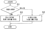
본 발명의 제 1 양상에 따른 차량 제어 시스템은 상기 차량이 선회하고 있는 경우, 상기 스포티-모드 회전수 산출 수단에 의해 결정된 목표 회전수를 유지하는 수단을 더 포함할 수 있다.The vehicle control system according to the first aspect of the present invention may further comprise means for maintaining a target rotation speed determined by the sporty-mode rotation speed calculating means when the vehicle is turning.
본 발명의 제 1 양상에 따른 차량 제어 시스템에서는, 상기 노멀-모드 회전수 산출 수단에 의해 결정된 목표 회전수가 상기 스포티-모드 회전수 산출 수단에 의해 결정된 목표 회전수보다 더 큰 경우, 상기 최종 회전수 지시 수단은 현 시점에 있어서의 상기 스포티-모드 회전수 산출 수단에 의해 결정된 목표 회전수와, 차량에서 발생된 최대 가속도를 일으키는 회전수 사이의 차이를 구동력의 요구량에 기초하여 보간함으로써 구한 회전수를 달성하기 위해 상기 회전수 제어 기구를 제어할 수 있다.In the vehicle control system according to the first aspect of the present invention, when the target rotation speed determined by the normal-mode rotation speed calculating means is greater than the target rotation speed determined by the sporty-mode rotation speed calculating means, the final rotation speed The indicating means calculates the rotation speed obtained by interpolating the difference between the target rotation speed determined by the sporty-mode rotation speed calculating means at this time and the rotation speed causing the maximum acceleration generated in the vehicle based on the required amount of driving force. The rotation speed control mechanism can be controlled to achieve.
본 발명의 제 1 양상의 차량 제어 시스템에 따르면, 지표에 따른 가속 성능을 초과하는 가속에 대한 요구가 이루어진 경우, 향상된 정확도로 구동력의 요구량을 반영시킨 제어를 허용하도록, 구동력의 요구량에 따른 그 시점에서의 최대 회전수까지 과도한 가속을 안분함으로써 구해지는 구동원의 회전수가 실현된다.According to the vehicle control system of the first aspect of the present invention, when a demand for acceleration exceeding the acceleration performance according to the indicator is made, the timing according to the demand amount of the driving force to allow the control reflecting the demand amount of the driving force with improved accuracy. The rotation speed of the drive source obtained by restraining excessive acceleration up to the maximum rotation speed at is realized.
본 발명의 제 1 양상의 차량 제어 시스템에서, 상기 차량 제어 시스템은, 상기 지표가 증가하는 동안, 상기 지표가 제 1 임계치에 도달할 때까지 상기 차량의 가속 성능의 향상 제어를 실행하지 않을 수 있고, 상기 지표가 상기 제 1 임계치에 도달한 후에는 상기 차량의 가속 성능의 향상 제어를 실행할 수 있으며, 상기 차량 제어 시스템은, 상기 지표가 감소하는 동안, 상기 지표가 상기 제 1 임계치 보다 작은 제 2 임계치에 도달할 때까지, 상기 지표가 상기 제 1 임계치에 도달한 경우라도 상기 차량의 가속 성능의 향상 제어를 실행할 수 있고, 상기 지표가 상기 제 2 임계치에 도달한 후에는 상기 차량의 가속 성능의 향상 제어를 금지할 수 있다.In the vehicle control system of the first aspect of the present invention, the vehicle control system may not execute the enhancement control of the acceleration performance of the vehicle until the indicator reaches the first threshold while the indicator increases. And after the indicator reaches the first threshold, the control of improving the acceleration performance of the vehicle may be executed, and the vehicle control system may further include a second, wherein the indicator is smaller than the first threshold while the indicator decreases. Until the threshold is reached, even if the indicator reaches the first threshold, it is possible to execute an improvement control of the acceleration performance of the vehicle, and after the indicator reaches the second threshold, Enhancement control can be inhibited.
본 발명의 제 1 양상의 차량 제어 시스템에 따르면, 차량의 기민한 주행 또는 차량이 기민하게 주행시키는 조작의 부재로 인해 상기 지표가 미리 정해진 값보다 작은 경우, 그 지표에 기초하는 가속 성능의 향상 제어가 실행되지 않는다. 따라서 특히 기민한 주행 또는 그 조작을 하지 않은 상태로 어떠한 이유로 차량의 주행 상태가 일시적으로 변화하여 상기 지표가 증가한 경우에도, 그러한 주행 상태 또는 조작의 변화가 가속 성능의 향상 제어에 반영되지 않는다. 따라서, 특히 기민하지 않거나 또는 승차 안정감이 증가된 마일드한 주행을 계속 유지할 수 있다. 반대로, 상기 지표에 기초하는 가속 성능의 향상 제어가 실행되고 있는 상태로, 그 지표가 상기 제 1 임계치보다 작은 값까지 감소되는 경우에도, 그 지표에 기초하는 가속 성능의 향상 제어가 계속 행해지므로, 종전의 가속 성능에 기초한 차량의 주행을 허용한다. 그 결과, 향상된 정밀도로 운전자의 의도에 만족되도록 차량의 주행을 제어할 수 있다. 따라서, 지표의 값의 증가에 응답하는 가속 성능의 향상 제어의 개시와 지표의 값의 감소에 응답하는 가속 성능의 향상 제어의 종료 사이에 히스테리시스를 설정할 수 있으므로, 제어의 헌팅을 회피할 수 있다.According to the vehicle control system of the first aspect of the present invention, when the indicator is smaller than a predetermined value due to the agile running of the vehicle or the absence of a maneuvering operation of the vehicle, the improvement control of the acceleration performance based on the indicator is performed. It does not run. Therefore, even if the running state of the vehicle temporarily changes for some reason without agile driving or its operation, and the indicator increases, such a change in the driving state or operation is not reflected in the improvement control of the acceleration performance. Therefore, it is possible to keep the mild running which is not particularly agile or the riding stability is increased. On the contrary, even when the indicator decreases to a value smaller than the first threshold in the state where the acceleration performance-based improvement control is being executed, the acceleration control based on the indicator is continuously improved. Allows the vehicle to run based on previous acceleration performance. As a result, the driving of the vehicle can be controlled to satisfy the driver's intention with improved precision. Therefore, since hysteresis can be set between the start of the acceleration control improvement response in response to the increase in the value of the indicator and the end of the acceleration control in response to the decrease in the value of the indicator, hunting of control can be avoided.
본 발명의 제 1 양상의 차량 제어 시스템은 상기 지표에 따라 상기 차량의 주행 특성을 변화시키는 제어를 금지하는 스위치를 더 포함할 수 있다.The vehicle control system of the first aspect of the present invention may further include a switch for prohibiting the control of changing the running characteristic of the vehicle according to the indicator.
본 발명의 제 1 양상의 차량 제어 시스템에서는, 상기 지표 설정 수단은 상기 차량의 주행 중의 상기 지표를 반복하여 구할 수 있고, 상기 지표 설정 수단은 상기 지표의 구한 값이 전회치보다 큰 경우 상기 지표를 상기 구한 값으로 유지하는 지표 유지 수단, 및 상기 지표 유지 수단에 의해 유지된 상기 지표의 값과 상기 지표의 구한 값 사이의 편차의 시간 적분치 및 미리 정해진 임계치에 기초하여 상기 지표 유지 수단에 의해 유지된 상기 지표의 값을 감소시키는 지표 감소 수단을 포함할 수 있고, 상기 지표 유지 수단에 의해 유지된 상기 지표의 값이 감소되는 방식은 상기 편차의 시간 적분치에 따라 변화될 수 있다.In the vehicle control system according to the first aspect of the present invention, the indicator setting means can repeatedly obtain the indicator while the vehicle is traveling, and the indicator setting means returns the indicator when the obtained value of the indicator is larger than the previous value. Indicator holding means for holding at the determined value, and holding by the indicator holding means based on a time threshold value and a predetermined threshold value of the deviation between the value of the indicator held by the indicator holding means and the value obtained for the indicator. Indicator reduction means for reducing the value of the indicated indicator, and the manner in which the value of the indicator held by the indicator holding means is changed in accordance with the time integral of the deviation.
본 발명의 제 1 양상의 차량 제어 시스템에서는, 상기 지표 설정 수단은 상기 차량의 주행 중의 상기 지표를 반복하여 구할 수 있고, 상기 지표 설정 수단은 상기 지표의 구한 값이 전회치보다 큰 경우 상기 지표를 상기 구한 값으로 유지하는 지표 유지 수단, 및 상기 지표 유지 수단에 의해 유지된 상기 지표의 값과 상기 지표의 구한 값 사이의 편차의 시간 적분치 및 미리 정해진 임계치에 기초하여 상기 지표 유지 수단에 의해 유지된 상기 지표의 값을 감소시키는 지표 감소 수단을 포함할 수 있고, 상기 편차의 시간 적분치가 감소하는 경우, 상기 지표 유지 수단에 의해 유지된 상기 지표의 값이 증가될 수 있다.In the vehicle control system according to the first aspect of the present invention, the indicator setting means can repeatedly obtain the indicator while the vehicle is traveling, and the indicator setting means returns the indicator when the obtained value of the indicator is larger than the previous value. Indicator holding means for holding at the determined value, and holding by the indicator holding means based on a time threshold value and a predetermined threshold value of the deviation between the value of the indicator held by the indicator holding means and the value obtained for the indicator. Indicator reduction means for reducing the value of the indicated indicator, and when the time integral of the deviation decreases, the value of the indicator held by the indicator holding means can be increased.
본 발명의 제 1 양상의 차량 제어 시스템에서는, 상기 지표 설정 수단은 상기 차량의 주행 중의 상기 지표를 반복하여 구할 수 있고, 상기 지표 설정 수단은 상기 지표의 구한 값이 전회치보다 큰 경우 상기 지표를 상기 구한 값으로 유지하는 지표 유지 수단, 및 상기 지표 유지 수단에 의해 유지된 상기 지표의 값과 상기 지표의 구한 값 사이의 편차의 시간 적분치 및 미리 정해진 임계치에 기초하여 상기 지표 유지 수단에 의해 유지된 상기 지표의 값을 감소시키는 지표 감소 수단을 포함할 수 있고, 액셀레이트 조작 (accelerating operation) 에 대한 구동원의 출력 특성이 상기 지수 유지 수단에 의해 유지된 상기 지수의 값에 따라 변화될 수 있다.In the vehicle control system according to the first aspect of the present invention, the indicator setting means can repeatedly obtain the indicator while the vehicle is traveling, and the indicator setting means returns the indicator when the obtained value of the indicator is larger than the previous value. Indicator holding means for holding at the determined value, and holding by the indicator holding means based on a time threshold value and a predetermined threshold value of the deviation between the value of the indicator held by the indicator holding means and the value obtained for the indicator. Indicator reducing means for reducing the value of the indexed indicator, and the output characteristic of the drive source for the accelerating operation can be changed in accordance with the value of the index held by the index holding means.
본 발명의 상술한 및/또는 후술될 목적, 특징, 및 이점은 첨부 도면을 참조로 본 발명의 예시적인 실시형태의 다음 상세한 설명으로부터 보다 명백해질 것이며, 도면 내 동일한 도면 부호는 동일한 구성요소를 표시한다.
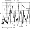
도 1 은 본 발명의 일 실시형태에 따른 전후 가속도 및 횡 가속도의 검출값을 타이어 마찰 원 상에 플롯하여 나타낸 도면이다.
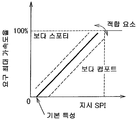
도 2 는 본 발명의 일 실시형태에 따른 순간 SPI 에 기초하는 지시 SPI 의 변화의 일례를 나타내는 도면이다.
도 3 은 본 발명의 일 실시형태에 따른, 순간 SPI 와 지시 SPI 사이의 편차의 시간에 대한 적분과, 그 적분치가 리셋되는 상황을 설명하는 도면이다.
도 4 는 본 발명의 일 실시형태에 따른 순간 SPI 와 요구 최대 가속도율 사이의 관계를 나타내는 맵이다.
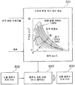
도 5 는 본 발명의 일 실시형태에 따른 각각의 요구 회전수 마다의 차속과 가속도 사이의 관계를 나타내는 그래프에, 지시 SPI 에 기초하는 요구 최대 가속도를 추가한 도면 및 상기 도면에 기초하여 최종 지시 회전수를 구하는 프로세스를 나타내는 도면이다.
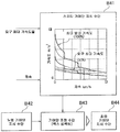
도 6 은 본 발명의 일 실시형태에 따른 각각의 변속단 마다의 차속과 가속도 사이의 관계를 나타내는 도면에 지시 SPI 에 기초하는 요구 가속도를 추가한 도면 및 상기 도면에 기초하여 최종 지시 변속단을 구하는 프로세스를 나타내는 도면이다.
도 7 은 본 발명의 일 실시형태에 따른 2 단 이상의 변속단을 가진 자동 변속기를 탑재한 차량에서 지시 SPI 에 기초하여 구한, 보정 변속단 및 보정 구동력을 변속 제어 및 엔진 출력 제어에 반영시킨 제어 블록도이다.
도 8 은 본 발명의 일 실시형태에 따른 2 단 이상의 변속단을 가진 자동 변속기를 탑재한 차량에서 지시 SPI 에 기초하여 구한, 보정 변속단 및 보정 구동력을 변속 제어 및 엔진 출력 제어에 반영시킨 다른 제어 블록도이다.
도 9 는 본 발명의 일 실시형태에 따른 2 단 이상의 변속단을 가진 자동 변속기를 탑재한 차량에서 지시 SPI 에 기초하여 구한, 보정 변속단 및 보정 구동력을 변속 제어 및 엔진 출력 제어에 반영시킨 또 다른 제어 블록도이다.
도 10 은 본 발명의 일 실시형태에 따른 지시 SPI 에 기초하여 구한 보정 기어비 및 보정 어시스트 토크를 조타 특성에 반영시킨 제어 블록도이다.
도 11 은 본 발명의 일 실시형태에 따른 지시 SPI 에 기초하여 구한 차량 높이, 보정 댐핑 계수 및 보정 스프링 상수를 현가 특성에 반영시키는 제어 블록도이다.
도 12 는 본 발명이 적용될 수 있는 차량의 일례를 개략적으로 나타내는 도면이다.
도 13 은 본 발명의 일 실시형태에 따른, 스포티-모드와 노멀-모드 사이의 조정의 실행과 조정의 비실행 또는 금지 사이의 전환을 위한 제어 예를 나타내는 플로우차트이다.
도 14 는 본 발명의 일 실시형태에 따른 지시 SPI 와 요구 최대 가속도율 사이의 관계를 정의한 다른 맵의 예를 나타내는 도면이다.The above, and / or following objects, features, and advantages of the present invention will become more apparent from the following detailed description of exemplary embodiments of the invention with reference to the accompanying drawings, in which like reference characters designate the same components. do.
BRIEF DESCRIPTION OF THE DRAWINGS It is a figure which plots and shows the detected value of the front-back acceleration and lateral acceleration on a tire friction circle which concerns on one Embodiment of this invention.
2 is a diagram showing an example of a change in the instruction SPI based on the instantaneous SPI according to one embodiment of the present invention.
FIG. 3 is a diagram for explaining the integral of the deviation time between the instantaneous SPI and the instruction SPI and the situation in which the integral value is reset according to an embodiment of the present invention.
4 is a map showing a relationship between an instantaneous SPI and a required maximum acceleration rate according to an embodiment of the present invention.
FIG. 5 is a graph showing a relationship between vehicle speed and acceleration for each required rotational speed according to an embodiment of the present invention, in which the required maximum acceleration based on the instruction SPI is added and the final indicated rotation based on the drawing; FIG. It is a figure which shows the process of finding a number.
FIG. 6 is a diagram illustrating a relationship between vehicle speed and acceleration for each shift stage according to an embodiment of the present invention, and a final instruction shift stage is obtained based on the diagram added with the required acceleration based on the instruction SPI. A diagram showing a process.
FIG. 7 is a control block in which a corrected shift stage and a corrected driving force, which are obtained based on an instruction SPI in a vehicle equipped with an automatic transmission having two or more shift stages according to one embodiment of the present invention, are reflected in the shift control and the engine output control. It is also.
8 is another control obtained by reflecting the corrected shift stage and the corrected driving force in the shift control and the engine output control, which are obtained based on an instruction SPI in a vehicle equipped with an automatic transmission having two or more shift stages according to an embodiment of the present invention. It is a block diagram.
FIG. 9 is a view illustrating another example in which a corrected shift stage and a corrected driving force, which are obtained based on an instruction SPI, in a vehicle equipped with an automatic transmission having two or more shift stages according to an embodiment of the present invention, are reflected in the shift control and the engine output control; FIG. Control block diagram.
10 is a control block diagram in which the steering gear ratio and correction gear ratio obtained based on the instruction SPI according to the embodiment of the present invention are reflected.
FIG. 11 is a control block diagram for reflecting a vehicle height, a correction damping coefficient, and a correction spring constant obtained on the basis of an instruction SPI according to an embodiment of the present invention to suspension characteristics. FIG.
12 is a view schematically showing an example of a vehicle to which the present invention can be applied.
FIG. 13 is a flowchart illustrating a control example for switching between execution of an adjustment between a sporty-mode and a normal-mode and non-execution or prohibition of the adjustment, according to an embodiment of the present invention.
14 is a diagram illustrating an example of another map in which a relationship between the indicated SPI and the required maximum acceleration rate according to one embodiment of the present invention is defined.
이하, 본 발명의 일 실시형태를 보다 구체적으로 설명한다. 본 실시형태는 운전자의 조작에 따라 가속, 감속 및 선회하는 차량에 적용되며, 차량의 전형적인 예가 내연 기관 및/또는 모터를 구동원으로 갖는 자동차이다. 차량의 일례를 도 12 의 블록도로 나타내고 있다. 도 12 에 나타내는 차량 (1) 은, 조타륜인 2 개의 전륜 (2) 과 구동륜인 2 개의 후륜 (3) 의 사륜을 구비한 차량이다. 이들의 사륜 (2, 3) 각각은 현가 장치 (4) 에 의해 차체 (도시 생략) 에 장착되어 있다. 이 현가 장치 (4) 는, 일반적으로 알려져 있는 현가 장치와 마찬가지로, 스프링과 쇼크업소버 (댐퍼) 를 주체로 하여 구성되어 있고 도 12 에는 쇼크업 소버 (5) 를 나타내고 있다. 도 12 에 나타내는 쇼크업소버 (5) 는, 기체나 액체 등의 유체의 유동 저항을 이용하여 완충 작용 또는 쇼크 흡수를 수행하도록 구성되고, 모터 (6) 와 같은 액추에이터에 의해 그 유동 저항의 크기를 변경할 수 있도록 구성되어 있다. 즉, 유동 저항을 증가시킨 경우에는, 차체가 잘 가라앉지 않아, 이른바 딱딱한 느낌이 되고, 차량의 거동으로는, 승차컴포트한 느낌이 적어져, 스포티감이 증대된다. 또한, 이들의 쇼크업소버 (5) 에 가압 기체를 급배 (공급 또는 배출) 함으로써 차 높이의 조정을 실시하도록 구성할 수도 있다.EMBODIMENT OF THE INVENTION Hereinafter, one Embodiment of this invention is described more concretely. The present embodiment is applied to a vehicle that accelerates, decelerates, and turns in response to a driver's operation, and a typical example of the vehicle is an automobile having an internal combustion engine and / or a motor as a drive source. An example of a vehicle is shown in the block diagram of FIG. The vehicle 1 shown in FIG. 12 is a vehicle provided with four wheels of two
전후륜 (2, 3) 각각에는, 브레이크 장치 (도시 생략) 가 형성되어 있다. 운전석에 배치되어 있는 브레이크 페달 (7) 을 밞음으로써 브레이크 장치가 동작하여 전후륜 (2, 3) 에 제동력을 부여하도록 동작한다.Brake devices (not shown) are formed in each of the front and
차량 (1) 의 구동원은, 내연 기관이나 모터 또는 이들의 조합과 같은, 일반적으로 알려져 있는 구동원이 있다. 도 12 에는 차량에 내연 기관 (또는 엔진) (8) 을 탑재하고 있고, 이 엔진 (8) 의 흡기관 (9) 에는, 흡기량을 제어하기 위한 스로틀 밸브 (10) 가 배치되어 있다. 전자 스로틀 밸브인 이 스로틀 밸브 (10) 는 모터와 같은 전기적으로 제어되는 액추에이터 (11) 에 의해 개방 및 폐쇄되도록 구성되어, 스로틀 밸브 (10) 의 개도가 필요에 따라 조정된다. 이 액추에이터 (11) 는, 운전석에 배치되어 있는 액셀레이터 페달 (12) 의 밟는 양, 즉 액셀 페달 스트로크에 따라 동작하여, 스로틀 밸브 (10) 의 개도를 특정 스로틀 개도로 제어하도록 구성되어 있다.The drive source of the vehicle 1 is a drive source generally known, such as an internal combustion engine, a motor, or a combination thereof. In FIG. 12, an internal combustion engine (or engine) 8 is mounted in a vehicle, and a
그 액셀레이터 페달 스트로크와 스로틀 개도 사이의 관계는 적절히 설정할 수 있다. 이들 양 사이의 관계가 1 대 1 관계에 가까울수록, 운전자는 바로 이 관계를 느끼게 되고 차량은 주행 특성으로서 스포티한 느낌 또는 승차감을 제공한다. 이것과는 반대로 액셀레이터 페달 스트로크에 대해 스로틀 개도가 상대적으로 작아지도록 이 관계를 설정하면, 차량의 거동 특성 또는 가속 특성은 (즉, 주행 특성) 은 마일드한 느낌이 된다. 차량이 구동원으로서 모터를 사용한 경우에는, 스로틀 밸브 (10) 대신에 인버터 또는 컨버터와 같은 전류 제어기가 제공되며, 액셀레이터 페달 스트로크에 따라 그 전류가 조정된다. 또한, 전류값과 액셀레이터 페달 스트로크 사이의 관계, 즉 거동 특성 또는 가속 특성 (즉, 주행 특성) 이 적절하게 변경된다.The relationship between the accelerator pedal stroke and the throttle opening degree can be appropriately set. The closer the relationship between these quantities is to the one-to-one relationship, the more the driver feels this relationship and the vehicle provides a sporty feel or ride as driving characteristics. On the contrary, if this relationship is set such that the throttle opening degree becomes relatively small with respect to the accelerator pedal stroke, the vehicle's behavior characteristics or acceleration characteristics (that is, the driving characteristics) become mild. When the vehicle uses a motor as a drive source, a current controller such as an inverter or a converter is provided instead of the
엔진 (8) 의 출력측에 변속기 (13) 가 연결되어 있다. 이 변속기 (13) 는, 입력 회전수와 출력 회전수 사이의 비율 즉 변속비를 적절히 변경하도록 구성된다. 예를 들어 일반적으로 알려져 있는 둘 이상의 기어단을 가진 자동 변속기나 벨트식 (belt-and-pulley type) CVT (무단 변속기) 또는 트로이달형 CVT 와 같은 무단 변속기이다. 변속기 (13) 는, 액추에이터 (도시 생략) 를 구비하고, 그 액추에이터를 적절히 제어함으로써 변속비를 스텝적 (단계적) 으로 변화시키거나, 또는 연속적으로 변화시키도록 구성되어 있다. 구체적으로는, 변속 맵이 미리 준비되고, 여기서 운전자에 의해 수행된 가속 동작에 기초한 액셀레이터 페달 스트로크 및 차속과 같은 차량 상태에 관련되어 변속비가 결정되고 변속 제어가 변속 맵에 따라 수행된다. 대안으로서, 목표 출력 또는 동력이 차속 및 액셀레이터 페달 스트로크와 같은 차량 상태에 기초하여 산출되고 목표 엔진 속도가 목표 출력 및 최적의 연비선으로부터 획득된다. 그 후, 목표 엔진 회전수를 실현하기 위해 변속 제어를 실행한다.The
위에 설명된 바와 같은 기본적인 변속 제어에 대조적으로, 연비 우선의 제어나 구동력을 증대시키는 제어를 선택될 수 있다. 연비를 우선하는 제어 하에서는 업 시프트를 상대적으로 저차속에서 실행하거나 상대적으로 고속측 기어비 또는 변속비를 저차속 측에서 사용한다. 구동력 또는 가속 특성을 향상시키는 제어에서는 업 시프트를 상대적으로 고차속에서 실행하거나 상대적으로 저속측 기어비 또는 변속비를 고차속 측에서 사용한다. 이들 제어는, 변속 맵을 전환하거나, 구동 요구량을 보정하거나, 또는 산출된 변속비를 보정함으로써 실시할 수 있다. 엔진 (8) 과 변속기 (13) 사이에는, 로크 업 클러치가 탑재된 토크 컨버터와 같은 전동 기구를 필요에 따라 형성할 수 있다. 그리고, 변속기 (13) 의 출력축은 종감속기로서 역할을 하는 차동 기어 (14) 를 통하여 후륜 (3) 에 연결되어 있다.In contrast to the basic shift control as described above, control of fuel economy priority or control to increase driving force can be selected. Under control that prioritizes fuel economy, upshift is performed at a relatively low vehicle speed, or a relatively high speed gear ratio or transmission ratio is used on the low vehicle speed side. In the control for improving driving force or acceleration characteristics, the upshift is performed at a relatively high vehicle speed, or a relatively low gear ratio or a gear ratio is used on the high vehicle speed side. These controls can be performed by switching the shift map, correcting the drive demand amount, or correcting the calculated shift ratio. Between the
전륜 (2) 을 전타 (turn) 하도록 동작하는 조타 기구 (15) 에 대해 설명한다. 스티어링 휠 (16) 의 회전 동작을 좌우의 전륜 (2) 에 전달하기 위한 스티어링 링키지 (17) 가 제공되고 스티어링 휠 (16) 의 조타 각도에 대한 조타력을 증가시키는 어시스트 기구 (18) 가 제공된다. 이 어시스트 기구 (18) 는, 액추에이터 (도시 생략) 를 구비하고, 그 액추에이터에 의해 제공된 어시스트 힘의 양 또는 토크의 양을 조정할 수 있도록 구성된다. 구체적으로, 어시스트 힘의 양을 감소시킴으로써 조타력과 전륜 (2) 에 제공된 실제의 전타력이 1 대 1 의 관계에 가까워져, 운전자의 조타의 다이렉트감이 증가되어, 차량의 주행 특성으로서 이른바 스포티한 느낌 또는 승차감을 제공한다. 이 경우, 조타각과 전륜 (2) 에 제공된 실제의 전타각 사이의 관계는 1 대 1 의 관계에 가까워진다. 또한 본 실시형태에서는, 지시 SPI가 증가한 만큼, 전동 파워 스티어링 (EPS) 기구에서의 기어비를 감소시킬 수 있어, 신속한 특성을 제공할 수 있다. 지시 SPI 가 동일한 값이면, 차속이 증가함에 따라 기어비가 증가되지만, 동일 차속의 경우, 지시 SPI가 증가하는 만큼 기어비를 감소시킬 수도 있다.The
또한, 특별히 도시하지 않지만, 상기의 차량 (1) 에는 차량 (1) 의 거동 또는 자세를 안정화시키기 위한 시스템으로서, 안티로크?브레이크?시스템 (ABS) 및/또는 이들 시스템을 통합하여 제어하는 비히클 스태빌리티 제어 시스템 (VSC) 이 제공된다. 이들 시스템은 일반적으로 알려져 있는 것으로서, 차체 속도와 차륜 속도의 차에 기초하여 차륜 (2, 3) 에 가해지는 제동력을 저하시키거나, 또는 차륜 (2, 3) 에 제동력을 부여하고, 나아가서는 제동력의 제어와 아울러 엔진 토크를 제어함으로써, 차륜 (2, 3) 의 로크나 슬립을 방지 또는 억제하여 차량의 거동을 안정시키도록 구성된다. 차량 (1) 에는 또한, 차량의 주행로나 차량의 주행 예정로에 관한 데이터 (즉 주행 환경) 를 얻을 수 있는 내비게이션 시스템이나, 스포티 모드와 노멀 모드 및 저연비 모드 (에코 모드) 등의 주행 모드를 수동 조작으로 선택하기 위한 스위치가 제공될 수도 있다. 또한, 차량 (1) 에는, 오르막 성능이나 가속 성능 또는 회두성과 같은 주행 특성을 변화시킬 수 있는 사륜 구동 기구 (4WD) 가 설치될 수도 있다.In addition, although not shown in particular, said vehicle 1 is a system for stabilizing the behavior or attitude of the vehicle 1, and an anti-lock brake system (ABS) and / or a vehicle staff which integrates and controls these systems. A capability control system (VSC) is provided. These systems are generally known, which lower the braking force applied to the
상기의 엔진 (8) 이나 변속기 (13) 또는 현가 장치 (4) 의 쇼크업소버 (5), 상기 어시스트 기구 (18), 상기 서술한 도시되지 않은 각 시스템 등을 제어하기 위한 데이터를 얻는 각종 센서가 제공된다. 센서들은 그 예를 들면, 전후륜 (2, 3) 의 회전수를 검출하는 차륜속 센서 (19), 액셀 스트로크 센서 (20), 스로틀 개도 센서 (21), 엔진 회전수 센서 (22), 변속기 (13) 의 출력 샤프트의 회전수를 검출하는 출력 회전수 센서 (23), 조타각 센서 (24), 전후 가속도 (Gx) 를 검출하는 전후 가속도 센서 (25), 횡방향의 가속도 (횡 가속도 (Gy)) 를 검출하는 횡 가속도 센서 (26), 요 레이트 센서 (27) 등을 포함한다. 이 연결에서, 상기의 안티로크?브레이크?시스템 (ABS) 이나 비히클 스태빌리티 컨트롤 시스템 (VSC) 등의 차량 거동 제어로 사용되고 있는 가속도 센서가 각 가속도 센서 (25, 26) 로서 이용될 수도 있다. 또한, 에어백을 탑재하고 있는 차량에서는, 에어백(들)의 전개 제어를 위해서 형성되어 있는 가속도 센서가 각 가속도 센서 (25, 26) 로서 이용될 수도 있다. 또한 전후 좌우의 가속도 (Gx, Gy) 는, 수평면 상에서 차량 전후 방향에 대해 소정 각도 (예를 들어 45°) 경사지게 하여 배치한 가속도 센서로 검출한 검출치를, 그 검출치를 전후 가속도 및 횡가속도로 분해하여 직접 얻을 수도 있다. 또한 전후 좌우의 가속도 (Gx, Gy) 는 센서에 의해 검출하는 것 대신에, 액셀레이터 페달 스트로크나 차속, 도로 부하, 조타 각도 등에 기초하여 연산하여 구해도 된다. 이들 센서 (19 ? 27) 는, 전자 제어 장치 (28 ; ECU) 에 검출 신호 (데이터) 를 전송하도록 구성되어 있고, 또 전자 제어 장치 (28) 는 그들의 데이터 및 미리 기억하고 있는 데이터 그리고 프로그램에 따라 연산을 실시하고, 그 연산 결과를 제어 지령 신호로 하여 상기 서술한 각 시스템 또는 그들의 액추에이터에 출력하도록 구성되어 있다. 또한, 합성 가속도는, 차량 전후 방향의 가속도 성분과, 차폭 방향 (횡 방향) 의 가속도 성분을 포함하는 가속도 등의 복수 방향의 가속도 성분을 포함하는 가속도에 한정되지 않는다. 합성 가속도로서, 오직 일 방향만의 가속도를 사용할 수도 있다. 예를 들어, 차량의 전후 방향에서의 가속도만을 합성 가속도로서 사용할 수도 있다.The various sensors which obtain data for controlling the shock absorber 5 of the said
본 발명에 따른 차량 제어 시스템는, 차량의 주행 상태를 차량의 거동 제어 (주행 제어) 에 반영시키도록 구성되어 있다. 여기에서 차량의 주행 상태는 전후 가속도나 횡가속도 또는 요잉이나 롤링 가속도, 또는 이들 둘 이상의 방향의 가속도를 합성한 가속도로 나타내어진다. 차량을 목표로 하는 속도로 주행시키거나 목표로 하는 방향으로 진행할 때 또는 노면 등의 주행 환경의 영향을 받아 차량의 거동을 원래 상태로 되돌리거나 할 때, 둘 이상의 방향의 가속도가 통상 발생한다. 이러한 점을 고려할 때, 차량의 주행 상태는 주행 환경이나 운전 지향을 어느 정도 반영하고 있는 것으로 고려된다. 이와 같은 배경에 기초하여 본 발명의 차량 제어 시스템은 차량의 주행 상태를 차량의 거동 제어에 반영시키도록 구성되어 있다.The vehicle control system according to the present invention is configured to reflect the running state of the vehicle to the behavior control (driving control) of the vehicle. Herein, the driving state of the vehicle is represented by forward and backward accelerations, lateral accelerations or yawing and rolling accelerations, or accelerations obtained by combining accelerations in two or more directions. Acceleration in two or more directions usually occurs when driving the vehicle at a target speed, traveling in a target direction, or returning the behavior of the vehicle to its original state under the influence of a driving environment such as a road surface. In view of this point, it is considered that the running state of the vehicle reflects to some extent the driving environment and driving orientation. Based on such a background, the vehicle control system of the present invention is configured to reflect the driving state of the vehicle to the behavior control of the vehicle.
상기 서술한 바와 같이, 차량의 거동은 가속 특성이나 회두성, 현가 장치 (4) 에 의한 지지 강성 (즉 범프?리바운드의 정도나 발생 용이성), 롤링이나 피칭의 정도 등을 포함한다. 본 발명에 따른 차량 제어 시스템은, 상기의 주행 상태에 기초하여 이들의 주행 특성을 변경한다. 그 경우, 상기의 주행 상태의 일례인 어느 방향의 가속도 또는 합성 가속도의 값을 가속도로 그대로 사용하여 주행 특성을 변경할 수도 있다. 그러나, 불편감을 보다 감소시키 위해, 상술한 가속도 또는 합성 가속도를 보정함으로써 얻은 지표를 사용할 수도 있다.As described above, the behavior of the vehicle includes acceleration characteristics and ashing characteristics, support stiffness (that is, the degree of bump and rebound or the likelihood of occurrence) by the
그 지표의 일례로서 스포티도 (SPI : Sports Index) 에 대해 설명한다. 여기에서, 스포티도 (SPI) 란, 운전자의 의도 또는 차량의 주행 상태를 나타내는 지표이다. 본 발명에서 채용할 수 있는 스포티도 (SPI) 는, 둘 이상의 방향의 가속도 (특히 그 절대치) 를 합성하여 구해지는 지표로서, 주행 방향에 대한 차량 거동에 크게 관계하는 가속도로서 전후 가속도 (Gx) 와 횡가속도 (Gy) 를 합성하여 구한 가속도가 그 예이다. 예를 들어, 순간 SPI 는 다음 식 (1) 에 따라 연산된다. 여기서, "순간 SPI" 는 차량의 주행 중에 있어서의 각 순간마다, 각 방향의 가속도가 구해지고, 그 가속도에 기초하여 산출되는 지표 또는 물리량을 의미한다. "각 순간마다" 는 가속도의 검출 및 그것에 기초하는 순간 SPI 의 산출이 소정의 사이클 타임으로 반복 실행되는 경우에는, 그 반복 간격을 의미한다.As an example of the index, the sport index (SPI) is explained. Here, sporty degree (SPI) is an index indicating the intention of the driver or the driving state of the vehicle. The sporty degree SPI that can be employed in the present invention is an index obtained by synthesizing the acceleration in two or more directions (particularly its absolute value). An example is the acceleration obtained by synthesizing the lateral acceleration (Gy). For example, the instantaneous SPI is calculated according to the following equation (1). Here, the "instantaneous SPI" means an index or physical quantity for which the acceleration in each direction is obtained and calculated based on the acceleration at each moment in the running of the vehicle. "Each instant" means the repetition interval when the acceleration is detected and the calculation of the instantaneous SPI based thereon is repeatedly executed at a predetermined cycle time.
순간 SPI = (Gx2+Gy2)1/2 ...(1)Instantaneous SPI = (Gx 2 + Gy 2 ) 1/2 ... (1)
상기의 연산식 (1) 에 사용되는 전후 가속도 (Gx) 중, 가속측 가속도 또는 감속측의 가속도 (즉 감속도) 중 적어도 어느 일방은, 정규화 처리된 것, 또는 가중 처리된 것을 사용해도 된다. 즉, 일반적인 차량에서는, 가속측의 가속도에 대해 감속측의 가속도 쪽이 크지만, 그 상이는 운전자에게는 거의 체감 또는 인식되지 않아, 대부분의 경우, 가속측 및 감속측의 가속도가 거의 동등하게 발생하고 있는 것으로 인식되고 있다. 정규화 처리는 이와 같은 실제의 값과 운전자가 느끼는 감각의 상이를 감소 또는 제거하기 위한 처리이다. 전후 가속도 (Gx) 에 대해서는, 가속측의 가속도를 크게 하거나, 또는 감속측의 가속도를 작게 하는 처리이다. 보다 구체적으로는, 각각의 가속도의 최대치의 비율을 구하고, 그 비율을 가속측 또는 감속측의 가속도에 곱하는 처리이다. 또한 가중 처리는 횡가속도에 대한 감속측의 가속도를 보정하도록 수행될 수 있다. 요약하면, 가중 처리는, 타이어에서 발생할 수 있는 전후 구동력 및 횡력이 타이어 마찰원으로 나타내어지는 것과 마찬가지로, 각 방향의 최대 가속도가 소정 반경의 원주 상에 위치하도록, 전후 (전방향 및 후방향) 가속도들의 적어도 하나에 가중치를 할당함으로써 보정을 실시하는 처리이다. 따라서, 이와 같은 정규화 처리와 가중 처리를 실시함으로써, 가속측의 가속도와 감속측의 가속도의 주행 특성에 대한 반영의 정도가 상이하게 된다. 가중 처리의 일례로서, 차량 전후의 감속 방향의 가속도와, 차량 전후의 가속 방향의 가속도 중, 가속 방향의 가속도의 영향도가, 감속 방향의 가속도의 영향에 대해 상대적으로 커지도록, 감속 방향의 가속도와 가속 방향의 가속도를 가중 처리할 수도 있다.At least one of the acceleration-side acceleration or the acceleration (ie, deceleration) of the deceleration side may use the normalized process or the weighted process among the front-back acceleration Gx used for said Formula (1). That is, in a typical vehicle, the acceleration side of the deceleration side is larger than the acceleration side of the acceleration side, but the difference is hardly felt or perceived by the driver, and in most cases, the acceleration side and the acceleration side decelerate almost equally. It is recognized that there is. The normalization process is a process for reducing or eliminating such actual value and the driver's sense of difference. About the front-back acceleration Gx, it is the process which increases the acceleration on the acceleration side, or makes the acceleration on the deceleration side small. More specifically, it is a process of obtaining the ratio of the maximum value of each acceleration, and multiplying the ratio by the acceleration on the acceleration side or the deceleration side. The weighting process may also be performed to correct the acceleration on the deceleration side with respect to the lateral acceleration. In summary, the weighting process is the forward and backward (forward and backward) acceleration such that the front and rear driving force and the lateral force that can occur in the tire are represented by the tire friction source, so that the maximum acceleration in each direction is located on the circumference of the predetermined radius. Is a process of performing a correction by assigning a weight to at least one of them. Therefore, by performing such normalization processing and weighting processing, the degree of reflection on the running characteristics of the acceleration on the acceleration side and the acceleration on the deceleration side is different. As an example of the weighting process, the acceleration in the deceleration direction is increased so that the influence of the acceleration in the acceleration direction in the deceleration direction before and after the vehicle and the acceleration in the acceleration direction before and after the vehicle becomes relatively large relative to the influence of the acceleration in the deceleration direction. And acceleration in the acceleration direction.
따라서, 가속도의 실제치와 가속도에 대하여 운전자가 느끼는 감각에는, 가속도의 방향에 따라 상이함이 있다. 예를 들어 요잉 방향이나 롤링 방향에서의 가속도와 전후 가속도에는, 그러한 상이가 있는 것으로 생각된다. 그래서 본 발명에 따르면, 방향이 상이한 가속도마다의 주행 특성에 대한 반영의 정도, 바꿔 말하면, 어느 방향의 가속도에 기초하는 주행 특성의 변화의 정도를, 다른 방향의 가속도에 기초하는 주행 특성의 변화의 정도와는 상이하도록 구성할 수 있다.Therefore, the driver feels about the actual value of acceleration and acceleration, and there exists a difference according to the direction of acceleration. For example, it is considered that there is such a difference between the acceleration in the yawing direction and the rolling direction and the acceleration before and after. Thus, according to the present invention, the degree of reflection on the running characteristic for each acceleration with different directions, in other words, the degree of change in the running characteristic based on the acceleration in one direction is determined by the change in the running characteristic based on the acceleration in the other direction. It can be configured to differ from the degree.
도 1 은 횡 가속도 (Gy) 의 센서값 및 상기의 정규화 처리 및 가중 처리를 실시한 전후 가속도 (Gx) 를 타이어 마찰원 상에 플롯한 예를 나타내고 있다. 이것은, 일반 도로를 모의한 테스트 코스를 주행한 경우의 일례이다. 도 1 로부터, 크게 감속하는 경우에 횡가속도 (Gy) 도 커지는 빈도는 높고, 타이어 마찰원을 따라 전후 가속도 (Gx) 와 횡가속도 (Gy) 가 발생하는 것은 일반적인 경향이라는 것을 알 수 있다.1 shows an example in which the sensor value of the lateral acceleration Gy and the front and rear acceleration Gx subjected to the above normalization and weighting process are plotted on the tire friction source. This is an example in the case of running the test course which simulated the general road. It can be seen from FIG. 1 that the frequency of lateral acceleration Gy also increases when the motor decelerates greatly, and it is a general trend that front and rear acceleration Gx and lateral acceleration Gy occur along the tire friction source.
본 실시형태에 따르면, 상기의 순간 SPI 로부터 지시 SPI 가 구해진다. 이 지시 SPI 는, 주행 특성을 변경하는 제어에 사용되는 지표이다. 지시 SPI 는 그 산출의 기초가 되는 상기 순간 SPI 의 증대에 대해서는 즉시 증대되고, 순간 SPI 의 저하에 대해 늦게 저하되도록 구성한 지표이다. 특히, 소정 조건의 만족을 요인으로 하여 지시 SPI 를 저하시킨다. 도 2 는 순간 SPI 의 변화에 기초하여 구해진 지시 SPI 의 변화를 나타내고 있다. 도 2 에 나타내는 예에서는, 순간 SPI 는 상기의 도 1 에 플롯하고 있는 값으로 나타내고, 이에 반하여, 지시 SPI 는, 순간 SPI 의 극대치로 설정되고, 소정의 조건이 만족될 때까지 동일한 값 (즉, 전회값) 으로 유지된다. 즉, 지시 SPI 는, 증대측으로는 신속하게 변화되고, 저하측으로는 상대적으로 늦게 변화하는 지표이다. According to this embodiment, the instruction SPI is obtained from the instantaneous SPI. This instruction SPI is an index used for the control for changing the running characteristic. The instruction SPI is an index configured to immediately increase with respect to the increase of the instantaneous SPI, which is the basis of the calculation, and to decrease later with respect to the decrease of the instantaneous SPI. In particular, the instruction SPI is lowered based on the satisfaction of the predetermined condition. Fig. 2 shows the change of the indicated SPI obtained based on the change of the instantaneous SPI. In the example shown in FIG. 2, the instantaneous SPI is represented by the value plotted in FIG. The previous value). That is, the instruction SPI is an indicator that changes rapidly on the increasing side and relatively late on the decreasing side.
보다 구체적으로, 도 2 에 있어서의 제어의 개시로부터 T1 의 시간대에서는, 예를 들어 차량이 감속 선회한 경우 등, 그 가속도의 변화에 의해 얻어지는 순간 SPI 가 증가 및 감소된다. 이 기간에, 전회의 극대치를 상회하는 순간 SPI 가, 상기 서술한 소정 조건의 만족에 선행하여 발생하기 때문에, 지시 SPI 가 단계적으로 증대되고, 증가된 지시 SPI 는 유지된다. 이에 반하여 t2 시점 또는 t3 시점에서는, 예를 들어 차량이 선회 가속으로부터 직선 가속으로 이행한 경우 등, 저하를 위한 조건이 만족됨으로써 지시 SPI 가 저하된다. 따라서, 지시 SPI 를 저하시키는 조건은, 지시 SPI 를 종전의 큰 값으로 유지하는 것이 운전자의 의도와 맞지 않는 것으로 생각되는 상태가 만족된다. 본 실시형태에서는 특정 시간의 경과를 요인으로 하여 만족된다.More specifically, in the time zone T1 from the start of control in FIG. 2, the instantaneous SPI obtained by the change in acceleration, for example, when the vehicle decelerates and turns, increases and decreases. In this period, since the moment SPI exceeding the previous maximum value occurs prior to the satisfaction of the above-described predetermined condition, the instruction SPI is increased step by step, and the increased instruction SPI is maintained. On the other hand, at the time t2 or the time t3, the instruction SPI is lowered when the conditions for the fall, such as when the vehicle shifts from the turning acceleration to the linear acceleration, are satisfied. Therefore, the condition which lowers the instruction SPI satisfies a condition in which it is considered that keeping the instruction SPI at a previous large value does not match the intention of the driver. In this embodiment, it is satisfied based on the passage of a specific time.
즉, 지시 SPI 를 종전의 큰 값으로 유지하는 것이 운전자의 의도를 반영한 것으로 생각되지 않는 상태는, 종전값으로 유지되고 있는 지시 SPI 와 그 순간에 발생하고 있는 순간 SPI 사이의 편차가 상대적으로 크며, 또한 그 편차가 커져 계속 축적되고 있는 상태이다. 따라서, 예를 들어, 차량이 선회 가속 제어되는 경우 등, 운전자에 의해 액셀 페달 (12) 을 일시적으로 느슨하게 하는 등의 조작에서 기인하는 순간 SPI 에 의해서는 지시 SPI 를 저하시키지 않는다. 예를 들어, 느슨하게 감속으로 이행한 경우 등, 운전자에 의해 액셀 페달 (12) 을 연속적으로 느슨하게 하는 등의 조작에서 기인하는 순간 SPI 가, 유지되고 있는 지시 SPI 를 하회하고 있는 상태가 소정 시간 계속된 경우에, 지시 SPI 를 저하시키는 조건이 만족되는 것으로 결정된다. 따라서, 지시 SPI 의 저하 개시 조건은, 순간 SPI 가 지시 SPI 를 하회하고 있는 상태의 계속 시간일 수 있다. 또한, 실제의 주행 상태를 보다 정확하게 지시 SPI 에 반영시키기 위해서, 유지되고 있는 지시 SPI 와 순간 SPI 의 편차의 시간 적분치 (또는 누적치) 가 미리 정해진 임계치에 도달하는 것을 지시 SPI 의 저하 개시 조건으로 할 수 있다. 그 임계치는, 운전자의 의도를 따른 주행 실험이나 시뮬레이션 또는 실제 차에서의 체험에 기초하는 앙케이트의 결과 등에 기초하여 적절히 설정할 수 있다. 후자의 편차의 시간 적분치를 사용하는 것으로 하면, 지시 SPI 와 순간 SPI 의 편차 및 시간의 관점에서, 지시 SPI 를 저하시키게 되므로, 실제의 주행 상태 또는 거동을 보다 정확하게 반영한 주행 특성의 변경 제어를 수행할 수 있다.That is, in a state in which the instruction SPI is not considered to reflect the driver's intention, the deviation between the instruction SPI held at the previous value and the instantaneous SPI occurring at that moment is relatively large. Moreover, the deviation is large and it is accumulating continuously. Therefore, the instruction SPI is not lowered by the instantaneous SPI resulting from, for example, the operation of loosening the
또한, 도 2 에 나타내는 예에서는, 상기의 t2 시점에 도달할 때까지 동일한 값으로 유지되는 지시 SPI 의 유지 시간이, t3 시점에 도달할 때까지의 지시 SPI 의 유지 시간보다 길게 되어 있는데, 이것은 이하의 제어를 실시하도록 구성되어 있기 때문이다. 즉, 상기 서술한 T1 의 시간대의 종기에 지시 SPI 가 소정치로 증대되어 유지되고, 그 후, 상기 서술한 저하 개시 조건이 만족되기 전의 t1 시점에 순간 SPI 가 증대되고, 또한 소정치로 유지되고 있는 지시 SPI 와 순간 SPI의 편차 적분치가 미리 정해진 소정치 이하로 되어 있다. 그 소정치는, 운전자의 의도를 따른 주행 실험이나 시뮬레이션을 실시하거나, 또는 순간 SPI 의 산출 오차를 고려하여 적절히 설정할 수 있다. 따라서, 순간 SPI 가 소정치로 유지되고 있는 지시 SPI 에 가까워졌다는 것은, 그 시점의 주행 상태가, 소정치로 유지되고 있는 지시 SPI 의 기초가 된 순간 SPI 를 발생시킨 가감속 상태 및/또는 선회 상태에 있다고 결정된 상태 또는 가감속 상태 및/또는 선회 상태에 가까운 상태로 되고 있는 것을 의미하고 있다. 즉 지시 SPI 가 유지되어 있는 SPI 값으로 증대시킨 시점으로부터 어느 정도 시간이 경과했다고 하더라도, 주행 상태는 그 시간이 경과하기 전의 시점에 얻은 주행 상태와 근사하고 있기 때문에, 순간 SPI 가 유지되고 있는 지시 SPI 를 하회하는 상태라도, 상기 서술한 저하 개시 조건의 만족을 지연시켜, 지시 SPI 를 종전의 소정치로 유지시킨다. 그 지연을 위한 제어 또는 처리는, 상기 서술한 경과 시간의 합 (누적치) 이나 편차의 적분치를 리셋하여, 경과 시간의 적산이나 상기 편차의 적분을 재개하거나, 또는 그 합 (적산치) 또는 적분치를 소정량 줄이거나, 나아가서는 적산 또는 적분을 일정 시간 중단하거나 하여 실시할 수도 있다.In addition, in the example shown in FIG. 2, the holding time of the instruction SPI maintained at the same value until the time t2 is reached is longer than the holding time of the instruction SPI until reaching the time t3. It is because it is comprised so that control may be performed. That is, the instruction SPI increases and is maintained at the end of the time zone of T1 described above to a predetermined value, and thereafter, the instantaneous SPI is increased and maintained at a predetermined value at time t1 before the above-described lowering start condition is satisfied. The deviation integrated value between the indicated SPI and the instantaneous SPI is less than or equal to a predetermined value. The predetermined value can be appropriately set in consideration of driving experiments or simulations in accordance with the driver's intention or in consideration of calculation errors of the instantaneous SPI. Therefore, the fact that the instantaneous SPI is close to the instruction SPI maintained at the predetermined value means that the acceleration and deceleration state and / or the turning state that generated the instantaneous SPI at which the driving state at that point of time becomes the basis of the instruction SPI maintained at the predetermined value. It means that it is in a state determined to be in the state or in a state close to the acceleration / deceleration state and / or the turning state. That is, even if a certain amount of time has elapsed from the time when the instruction SPI is increased to the held SPI value, the driving state is close to the driving state obtained before the time elapses, so that the instantaneous SPI is maintained. Even if it is below the state, the satisfaction of the above-described lowering start condition is delayed, and the instruction SPI is maintained at the previous predetermined value. The control or processing for the delay resets the sum (accumulated value) of the elapsed time or the integral value of the deviation, and resumes the integration of the elapsed time or the integration of the deviation, or the sum (integrated value) or the integral value of the elapsed time. The predetermined amount may be reduced, or further, the integration or integration may be interrupted for a predetermined time.
도 3 은 상기 서술한 편차의 적분과 그 리셋을 설명하는데 유용한 개략도이다. 도 3 에 해칭 표시한 부분의 면적이 편차 적분치를 나타낸다. 그 프로세스에서, 순간 SPI 와 지시 SPI 사이의 차이가 소정치 (Δd) 이하가 된 t11 시점에 적분치가 리셋되고 제로로 리턴되며, 상기 편차 또는 차이값의 적분이 다시 개시된다. 즉, 이 시점에서 얻은 순간 SPI와 소정의 값으로 유지되는 지시 SPI 사이의 차이가 임계치 이하인지 여부에 기초하여 적분치가 리셋된다. 따라서, 지시 SPI 를 감소시키는 개시 조건이 만족되지 않고 따라서, 지시 SPI 는 이전에 구한 소정의 값으로 유지된다. 그 후, 적분을 재개한 후, 순간 SPI 가 유지되고 있는 지시 SPI 보다 큰 값이 되면, 지시 SPI 가 순간 SPI 에 따른 큰 값으로 업데이트되고, 또한 이 값으로 유지되어 상기 적분치가 리셋된다.3 is a schematic diagram useful for explaining the integration of the above-described deviations and their reset. The area of the part hatched in FIG. 3 represents a deviation integral value. In that process, the integral value is reset and returned to zero at the time t11 when the difference between the instantaneous SPI and the indicated SPI becomes less than or equal to the predetermined value [Delta] d, and the integration of the deviation or difference value is started again. In other words, the integral value is reset based on whether the difference between the instantaneous SPI obtained at this point and the indicated SPI maintained at the predetermined value is equal to or less than the threshold. Therefore, the starting condition for reducing the instruction SPI is not satisfied, and therefore, the instruction SPI is maintained at a previously obtained predetermined value. Thereafter, after resuming the integration, if the instantaneous SPI becomes a value larger than the maintained SPI, the instructed SPI is updated to a large value corresponding to the instantaneous SPI, and is maintained at this value to reset the integral value.
상기의 적분치에 기초하여 지시 SPI 저하 제어 개시의 조건을 판단하는 경우, 지시 SPI 의 저하의 정도 또는 구배를 상이하게 할 수도 있다. 상기 서술한 적분치는, 유지되고 있는 지시 SPI 와 순간 SPI 의 편차를 시간에 대해 적분한 값이기 때문에, 상기 편차가 크면 비교적 단시간에 적분치가 소정치에 도달하여 상기 조건이 만족된다. 상기 편차가 작은 경우에는, 상기 적분치가 소정치에 도달하는데 상대적으로 긴 시간이 걸려 상기 조건이 만족된다.When determining the condition of the instruction SPI lowering control start based on the integral value, the degree or gradient of the instruction SPI lowering may be different. Since the above-mentioned integral value is a value obtained by integrating the deviation between the held instruction SPI and the instantaneous SPI with respect to time, when the deviation is large, the integral value reaches a predetermined value in a relatively short time and the condition is satisfied. In the case where the deviation is small, it takes a relatively long time for the integrated value to reach a predetermined value and the condition is satisfied.
따라서, 지시 SPI 의 감소 정도 또는 레이트가 예를 들어, 상기 지시 SPI 를 감소시키는 개시 제어의 조건이 만족될 때까지의 경과 시간의 길이에 따라 변경될 수 있다. 상기 조건이 단시간에 만족되면, 소정치로 유지되고 있는 지시 SPI 에 대한 순간 SPI 의 저하폭이 큰 것이 되어, 지시 SPI 가 그 때의 운전자의 의도와 크게 벗어난 것이 된다. 그래서, 이와 같은 경우에는, 지시 SPI 를 큰 비율 또는 높은 정도로 저하시킨다. 이것과는 반대로, 상기 조건이 만족될 때까지의 시간이 상대적으로 긴 경우에는, 유지되고 있는 지시 SPI 에 대한 순간 SPI 의 저하폭이 작은 것이 되어, 유지되고 있는 지시 SPI 가 그 시점의 운전자의 의도와 특히 크게 벗어난 것이라고는 할 수 없다. 그래서, 이와 같은 경우에는, 지시 SPI 를 작은 비율 또는 구배로 천천히 저하시킨다. 이렇게 함으로써, 주행 특성을 설정하기 위한 지시 SPI 와 운전자의 의도와의 편차를 신속 또한 정확하게 보정 (감소 또는 제거) 하여, 주행 상태에 적합한 차량의 주행 특성을 설정할 수 있게 된다.Thus, the degree or rate of decrease of the indication SPI can be changed, for example, according to the length of time that elapses until the condition of the start control of reducing the indication SPI is satisfied. If the above condition is satisfied in a short time, the decrease in the instantaneous SPI for the instruction SPI maintained at the predetermined value is large, and the instruction SPI is greatly out of the intention of the driver at that time. Therefore, in such a case, the instruction SPI is lowered by a large ratio or a high degree. On the contrary, in the case where the time until the above condition is satisfied is relatively long, the instantaneous SPI decreases with respect to the held instruction SPI so that the fall of the instantaneous SPI is small, and the maintained instruction SPI is the driver's intention at that time. This is not a big departure. Thus, in such a case, the indicated SPI is slowly lowered at a small rate or gradient. By doing so, the deviation between the instruction SPI for setting the driving characteristic and the driver's intention can be corrected (reduced or eliminated) quickly and accurately, so that the running characteristic of the vehicle suitable for the driving state can be set.
상기 서술한 순간 SPI 노면 구배나 코너의 유무 또는 그 곡률 등의 주행 환경, 또한 운전자의 운전 지향과 같은 주행 환경을 포함한 주행 상태를 나타낸다. 차량이 주행하는 주행로 상태에 따라 차량의 가속도가 변화됨과 함께, 주행로 상태에 따라 운전자는 가감속 조작 및 선회 조작을 실시하고, 나아가서는 운전자 조작에 따라 가속도가 변화되기 때문이다. 본 실시형태에 따른 차량 제어 시스템은, 그 지시 SPI 를 차량의 주행 특성의 제어에 이용하도록 구성되어 있다. 본 실시형태에 있어서의 주행 특성에는, 가속 특성이나 조타 특성, 서스펜션 특성, 소리 특성 등이 포함되고, 이들의 특성은, 상기 서술한 스로틀 밸브 (10) 의 제어 특성, 변속기 (13) 의 변속 특성, 현가 장치 (4) 에 있어서의 쇼크업소버 (5) 에 의한 감쇠 특성, 어시스트 기구 (18) 의 어시스트 특성 등을, 각각의 컴포넌트 또는 기구에 제공된 액추에이터에 의해 필요에 따라 설정한다. 그 주행 특성의 변화의 일반적인 경향은, 지시 SPI 가 클수록, 이른바 차량의 스포티한 주행이 가능해지는 주행 특성의 변화이다. 즉, 본 실시형태의 지시 SPI 는 조작 특성, 가속 특성 또는 거동 특성을 변화시키는 파라미터이다. 조작 특성은 핸들이나 액셀레이터 페달 또는 브레이크 페달 등의 조작자에 대한 모터나 엔진 혹은 변속 장치, 혹은 스티어링이나 브레이크의 어시스트 장치의의 액츄에이터의 제어량 또는 제어 속도의 특성을 포함한다. 또 가속 특성 또는 거동 특성은, 예를 들어, 소정의 지령값에 기초하여 제어되는, 주행에 관련된 액티브 스태빌라이져 (stabilizer) 나 서스펜션 등의 액츄에이터의 제어 특성을 포함한다.The driving conditions described above include the driving environment such as the instantaneous SPI road surface gradient, the presence or absence of a corner, the curvature thereof, and the driving environment such as the driver's driving orientation. This is because the acceleration of the vehicle changes according to the driving path state in which the vehicle runs, and the driver performs the acceleration / deceleration operation and the turning operation according to the driving path state, and further, the acceleration changes according to the driver operation. The vehicle control system according to the present embodiment is configured to use the instruction SPI for controlling the running characteristics of the vehicle. The running characteristics in the present embodiment include acceleration characteristics, steering characteristics, suspension characteristics, sound characteristics, and the like, and these characteristics include the control characteristics of the
그러한 주행 특성의 변경의 일례로서 도 4 에 나타내는 바와 같이, 가속 특성 또는 성능을 지시 SPI 에 따라 변경한다. 이 예에서는, 상기 서술한 바와 같이 설정되는 지시 SPI 에 대응시켜 요구 최대 가속도율을 구한다. 여기에서 요구 최대 가속도율이란, 여유 구동력을 규정하며, 예를 들어 100 % 와 동일한 요구 최대 가속도율은 차량에서 발생될 수 있는 최대의 가속도를 가능하게 하는 상태를 나타내며, 변속기 (13) 의 변속비는 엔진 회전수가 최대가 되는 변속비 또는 가장 큰 변속비 (가장 저차속 측의 변속비) 로 설정된다. 예를 들어 50 % 와 동일한 요구 최대 가속도율은 차량이 발생시킬 수 있는 최대의 가속도 절반의 가속도를 가능하게 하는 상태를 나타내며, 변속기 (13) 의 변속비는 중간의 변속비로 설정된다. 도 4 에 나타내는 예에서는, 지시 SPI 가 커질수록 요구 최대 가속도율이 커진다. 도 4 에 실선으로 나타내는 기본 특성은, 차량을 실제로 주행시키는 동안 얻어진 데이터에 기초하여 지시 SPI 와 요구 최대 가속도율의 관계를 계산하여 구한 것으로서, 실제 차량의 주행 또는 시뮬레이션을 통하여 필요에 따라 정정을 행한 것이다. 이 기본 특성의 특성 선보다 요구 최대 가속도율이 커지는 측에 특성 선을 설정한 경우에는, 차량의 가속도가 상대적으로 커지므로, 이른바 스포티한 거동 특성 또는 가속 특성 (즉, 주행 특성) 이 된다. 이것과는 반대로 요구 최대 가속도율이 작아지는 측에 특성선을 설정한 경우에는, 차량의 가속도가 상대적으로 작아지므로, 차량의 큰 가속이 순간적으로 실현될 수 있어, 컴포트한 거동 특성 또는 가속 특성을 가져온다. 이들의 특성의 조정 (즉 적응 또는 튜닝) 은, 차량에 요구되는 상품성 등에 따라 필요에 따라 실시될 수 있다. 또한, 기본 특성에서는, 지시 SPI 가 제로보다 큰 상태에서 요구 최대 가속도율이 제로가 되도록 설정해 두는 것은, 교통 정체나 차고 주차와 같은 미속 주행 상태를 가속 특성을 설정 또는 변경하기 위한 제어에 반영시키지 않도록 했기 때문이다.As an example of such a change of the running characteristic, as shown in FIG. 4, the acceleration characteristic or the performance is changed in accordance with the instruction SPI. In this example, the required maximum acceleration rate is obtained in correspondence with the instruction SPI set as described above. Here, the required maximum acceleration rate defines the marginal driving force, for example, the required maximum acceleration rate equal to 100% indicates a state that enables the maximum acceleration that can be generated in the vehicle, and the transmission ratio of the
상기의 요구 최대 가속도율을 변속기 (13) 의 변속 특성에 반영시켜 가속 특성을 변경하는 경우의 제어에 대해 설명한다. 변속기 (13) 로서 무단 변속기를 탑재하고 있는 차량 또는, 엔진 회전수를 모터에 의해 제어할 수 있는 하이브리드차에서는, 차속이나 구동 요구량에 기초하여 목표 출력 또는 구동력을 산출하고, 그 목표 출력 또는 구동력을 달성하도록 엔진 속도를 제어한다. 그 요구 회전수마다의 차속과 가속도의 관계는 도 5 에 나타나 있고, 상기 서술한 도 4 에 기초하여 지시 SPI 로부터 구해진 요구 최대 가속도율을 도 5 의 그래프에 추가한다. 예를 들어 도 5 의 굵은 실선은 이렇게 추가된 100 % 와 50 % 라는 요구 최대 가속도율을 나타낸다. 따라서, 지시 SPI 로부터 구해진 요구 최대 가속도를 나타내는 선과 현재 시점의 차속을 나타내는 선의 교점을 통과하는 선으로 나타내어지는 회전수가 요구 회전수가 된다.The control in the case where the acceleration characteristic is changed by reflecting the required maximum acceleration rate in the transmission characteristic of the
상기 서술한 도 12 를 참조하여 설명한 바와 같은 변속기 (13) 를 구비하고 있는 차량에서는, 그 변속기 (13) 에 의해 설정해야 하는 변속비를 제어하기 위해서, 기본적인 변속 맵이 제공된다. 그 변속 맵은, 무단 변속기에 대해서는, 차속과 엔진 회전수에 따라 변속비를 설정한다. 그 변속비 제어의 일례는, 일반적으로, 토크 디맨드 제어로서 알려져 있는 제어로서, 예를 들어 구동 요구량으로서의 액셀레이터 페달 스트로크와 차속에 기초하여 구동력 맵으로부터 요구 구동력을 구하고, 그 요구 구동력과 차속 또는 엔진 회전수로부터 엔진의 요구 출력을 구한다. 그 요구 출력을 최적 연비로 출력하는 목표 엔진 회전수가 엔진 회전수 맵에 기초하여 구해지고, 그 목표 엔진 회전수를 달성하도록 무단 변속기의 변속비가 제어된다. 즉, 변속기 (13) 를 구동원인 엔진의 회전수 제어 기구로서 기능시킨다. 또한, 엔진의 출력은 토크와 회전수의 곱으로 구해지기 때문에, 상기의 목표 엔진 회전수 또는 이것에 상당하는 차속에 기초하여 요구 출력을 달성하는 엔진 토크가 구해지고, 그 엔진 토크를 제공하는 스로틀 개도가 산출된다.In the vehicle provided with the
도 5 에 나타내는 스포티 모드 회전수 지시 수단 (B31) 은, 상기 서술한 지시 SPI 에 기초하여 구해진 요구 회전수 (엔진 회전수) 를 지시하는 수단으로서 스포티 회전수 산출 수단이라고 할 수 있다. 또한, 노멀 모드 회전수 지시 수단 (B32) 은, 토크 디맨드 제어 등의 통상적인 엔진 회전수 제어로 구해진 목표 회전수 (엔진 속도) 를 지시하는 수단로서 본 발명에 따른 노멀 모드 회전수 산출 수단에 대응한다. 이들의 이른바 노멀 모드 회전수와 상기의 이른바 스포티 모드 회전수가 회전수 조정 수단 (B33) 에 의해 비교되고 (조정되고), 큰 값을 가진 회전수가 선택되는데, 이른바 "맥스 셀렉트"라 한다. 이렇게 하여 선택된 회전수가 최종 회전수 지시 수단 (B34) 에 의해 제어 신호로서 출력된다. 따라서, 액셀레이터 페달 스트로크가 작아, 노멀 모드 회전수가 스포티 모드 회전수보다 저회전수인 경우에는, 스포티 모드 회전수가 유지되게 된다. 또한, 액셀레이터 페달이 크게 밟히는 때와 같이, 구동력의 요구량이 요구 최대 가속도를 초과하면 다운 시프트가 실발생한다.The sporty mode rotational speed indicating means B31 shown in FIG. 5 can be said to be a sporty rotational speed calculating means as a means for indicating the required rotational speed (engine rotational speed) obtained based on the above-mentioned instruction SPI. In addition, the normal mode rotation speed indicating means B32 corresponds to the normal mode rotation speed calculating means according to the present invention as a means for instructing a target rotation speed (engine speed) obtained by normal engine speed control such as torque demand control. do. These so-called normal mode rotational speeds and the so-called sporty mode rotational speeds described above are compared (adjusted) by the rotational speed adjustment means B33, and rotational speeds having a large value are selected, so-called "max select". The rotation speed selected in this way is output as a control signal by the final rotation speed indicating means B34. Therefore, when the accelerator pedal stroke is small and the normal mode rotational speed is lower than the sporty mode rotational speed, the sporty mode rotational speed is maintained. In addition, as when the accelerator pedal is greatly stepped down, when the required amount of driving force exceeds the required maximum acceleration, down-shift occurs.
이와 같은 제어는, 무단 변속기에 있어서는, 저차속측의 변속비 (큰 값의 변속비) 를 목표로 한 변속 제어이다. 그 결과, 제어하에서 변속비가 커짐으로써 최대 구동력 또는 엔진 브레이크력이 커져 차량의 거동이 높은 응답성으로 제어되며 따라서, 이른바 스포티감이 있는 특성, 또는 운전자의 운전 지향 또는 주행로 상태와 같은 주행 환경에 맞는 특성을 제공한다. 또한, 무단 변속기를 탑재하고 있는 차량에 대한 이와 같은 제어는, 모드 선택 스위치가 탑재되고, 그 스위치에 의해 예를 들어 스포티 모드가 선택되고 있는 경우에 실행할 수도 있다.Such control is shift control aimed at the gear ratio (large value gear ratio) of the low vehicle speed side in a continuously variable transmission. As a result, the greater the speed ratio under control, the greater the maximum driving force or the engine brake force, so that the behavior of the vehicle is controlled with high responsiveness, and thus the so-called sporty characteristics, or the driving environment of the driver's driving orientation or driving path conditions. Provide the right characteristics. Such control of a vehicle equipped with a continuously variable transmission can also be executed when a mode selection switch is mounted and a sporty mode is selected by the switch, for example.
한편, 변속기 (13) 는 둘 이상의 기어단을 갖는 변속기인 경우에는, 도 6 에 나타내는 바와 같이 제어된다. 둘 이상의 기어단을 갖는 변속 제어에서는, 목표로 하는 기어단이 정해지고 그 기어단을 설정하도록 변속기 (13) 의 액추에이터에 제어 지령 신호가 출력된다. 도 6 은 각 변속단마다 차속과 가속도의 관계를 나타낸다. 도 6 의 그래프에 추가된 굵은 실선은 지시 SPI 로부터 구해진 요구 최대 가속도율로서 100 % 및 50 % 의 요구 최대 가속도를 나타낸다. 따라서, 지시 SPI 로부터 구해진 요구 최대 가속도를 나타내는 선과 현재 시점의 차속을 나타내는 선의 교점에 가장 가까운 변속단의 선으로 나타내어지는 변속단이 목표 변속단이 된다.On the other hand, when the
본 발명에 관련된 제어 시스템에 의한 제어가 실행되고 있는 경우, 상기의 도 15 에서 구해진 스포티 목표 변속단과, 미리 준비되어 있는 변속선도에 기초하는 노멀 목표 변속단 (예를 들어, 액셀 조작과 차속에 기초하여 정해지는 변속비) 이 비교 (기어단 조정) 되고, 변속비가 큰 저차속측의 변속단이 선택되는데, 이를 "미니멈 셀렉트" 라 한다. 즉, 둘 이상의 기어단을 가진 변속기에 의한 노멀 목표 변속단은, 액셀레이터 페달 스트로크와 같은 구동 요구량과 차속에 의해 각 변속단의 영역을 정한 변속선도 (변속 맵) 에 기초하여 설정된다. 따라서 액셀 페달이 크게 밟히는 등, 요구 최대 가속도를 초과하는 구동 요구량으로 증대되면 다운 시프트가 발생하고, 또한 차속이 증대되면 업 시프트가 가능해진다.When control by the control system according to the present invention is being executed, the sporty target shift stage obtained in FIG. 15 described above, and a normal target shift stage based on a shift diagram prepared in advance (for example, based on an accelerator operation and a vehicle speed) (Speed ratio determined) is compared (gear stage adjustment), and the shift stage on the low vehicle speed side having a large speed ratio is selected, which is referred to as "minimum select". That is, the normal target shift stage by the transmission having two or more gear stages is set based on a shift diagram (shift map) in which the area of each shift stage is defined by the drive demand and the vehicle speed, such as an accelerator pedal stroke. Therefore, when the driving speed exceeds the required maximum acceleration, such as when the accelerator pedal is greatly stepped down, a downshift occurs. When the vehicle speed is increased, the upshift is possible.
도 6 에 나타내는 스포티 모드 기어단 지시 수단 (B41) 은, 상기 서술한 지시 SPI 에 기초하여 구해진 기어단을 지시하는 수단이고, 또 노멀 모드 기어단 지시 수단 (B42) 은 통상적인 액셀 페달 개도와 차속에 의한 변속선도에 기초하여 구해진 기어단을 지시하는 수단이다. 이들의 스포티 모드 기어단과 노멀 모드 기어단은 기어단 조정 수단 (B43) 에 의해 비교되고 (조정되고), 보다 저속측의 기어단 (보다 변속비가 큰 기어단) 이 선택되는데, 즉 "미니멈 셀렉트"가 행해진다. 이렇게 하여 선택된 기어단이 최종 기어단 지시 수단 (B44) 에 의해 제어 신호로서 발생한다. 즉, 변속기 (13) 를 구동원인 엔진의 회전수 제어 기구로서 기능시킨다. 따라서, 액셀레이터 페달 스트로크 등에 의해, 노멀 모드 기어단이 스포티 모드 기어단보다 고차속측의 기어단인 경우에는, 스포티 모드 기어단이 유지되고, 보다 저차속측의 기어단 (큰 변속비) 이 설정되게 된다.The sporty mode gear stage indicating means B41 shown in FIG. 6 is a means for instructing the gear stage calculated based on the instruction SPI described above, and the normal mode gear stage indicating means B42 is a normal accelerator pedal opening degree and a vehicle speed. Means for instructing a gear stage obtained based on the shift diagram. These sporty mode gear stages and normal mode gear stages are compared (adjusted) by the gear stage adjusting means B43, and a gear stage on a lower speed side (a gear stage with a higher speed ratio) is selected, that is, "minimal select". Is performed. The gear stage thus selected is generated as a control signal by the final gear stage indicating means B44. That is, the
이와 같은 제어는, 둘 이상의 기어를 가진 변속기에 있어서는, 저차속측의 기어단 (큰 값의 변속비) 을 목표로 한 변속 제어이다. 그 결과, 변속비가 커짐으로써 구동력 또는 엔진 브레이크력이 커지고, 차량의 거동이 높은 응답성으로 제어되어, 이른바 스포티감을 제공하는 특성, 또는 운전자의 운전 지향 또는 주행로 상태 등의 주행 환경에 맞는 특성을 제공한다. 또한, 이와 같은 제어는, 예를 들어, 모드 선택 스위치가 차량에 탑재되고, 그 스위치에 의해 이른바 스포티 모드가 선택되고 있는 경우에 실행될 수 있고, 스포티 모드가 선택되지 않은 경우에는 제어가 금지될 수도 있다.Such a control is shift control aimed at the gear stage (large speed ratio) of the low vehicle speed side in the transmission with two or more gears. As a result, the driving ratio or the engine braking force is increased by the transmission ratio being increased, and the behavior of the vehicle is controlled with high responsiveness, so that the so-called sportyness is provided, or the characteristic suitable for the driving environment such as the driver's driving orientation or driving condition. to provide. Further, such control can be executed, for example, when a mode selection switch is mounted on the vehicle, and a so-called sporty mode is selected by the switch, and control may be prohibited when the sporty mode is not selected. have.
상기 서술한 전자 제어 장치 (28) 은 도 5 에 나타내는 각 수단의 기능, 또는 도 6 에 나타내는 각 수단의 기능을 가질 수도 있다. 대안으로서, 스포티 모드 제어용 전자 제어 장치가 제공될 수 있고, 그 스포티 모드 제어용 전자 제어 장치가 상기 기능을 가질 수도 있다.The
즉, 구동력의 요구량의 증가에 따라, 엔진 속도가 증가되거나 또는 기어단이 저속측 기어단으로 변경되는 경우, 엔진 속도 또는 저속측 기어단은 다음과 같이 설정될 수 있다. 차량의 구동력 또는 구동력에 기초한 요구 가속도는 액셀레이터 페달 스트로크 및 차속과 같은 구동력의 요구량에 기초하여 결정된다. 따라서, 구동력의 요구량에 기초하여 얻은 요구 가속도가 상기 지시 SPI 및 차속에 기초하여 얻은 요구 최대 가속도율로부터 얻은 가속도를 초과하는 경우, 엔진 속도 또는 기어단은 액셀레이터 페달 스트로크와 같은 구동력의 요구량에 기초하여 얻은 요구 가속도를 발생시키도록 설정될 수 있다. 대안으로서, 구동력의 요구량이 증가되는 경우의 시점에서 발생될 수 있는 최대 가속도는 차속 및 변속비에 의해 결정되며, 엔진 속도 또는 기어단은 지시 SPI 에 기초하여 도 5 또는 도 6 으로부터 얻은 가속도 및 발생될 수 있는 최대 가속도 사이의 편차를 그 최대값에 대한 액셀레이터 페달 스트로크와 같은 구동력의 요구량의 비율로 비례적으로 나눔으로써 구한 가속도를 생성하도록 설정될 수 있다. 즉, 발생될 수 있는 최대 가속도와 지시 SPI 에 기초하여 예를 들어, 도 5 또는 도 6 으로부터 얻은 가속도 사이의 중간점이 구동력의 요구량에 따라 보간될 수 있다.That is, when the engine speed is increased or the gear stage is changed to the low gear side with the increase in the required amount of driving force, the engine speed or the low gear side can be set as follows. The required acceleration based on the driving force or driving force of the vehicle is determined based on the required amount of driving force such as the accelerator pedal stroke and the vehicle speed. Therefore, if the required acceleration obtained based on the required amount of driving force exceeds the acceleration obtained from the required maximum acceleration rate obtained based on the indicated SPI and the vehicle speed, the engine speed or gear stage is based on the required amount of driving force such as the accelerator pedal stroke. It can be set to generate the required acceleration required. Alternatively, the maximum acceleration that can be generated at the time when the demand for driving force is increased is determined by the vehicle speed and the gear ratio, and the engine speed or gear stage can be generated and the acceleration obtained from FIG. 5 or 6 based on the indicated SPI. It can be set to generate the acceleration obtained by proportionally dividing the deviation between the maximum acceleration that can be obtained by the ratio of the required amount of driving force, such as the accelerator pedal stroke to the maximum value. That is, the intermediate point between the acceleration obtained from, for example, 5 or 6 based on the maximum acceleration that can be generated and the indicated SPI can be interpolated according to the required amount of driving force.
지시 SPI 에 기초한 가속도는 구동력의 요구량에 기초한 가속도로 전환되는 경우, 전환의 제어 응답은 지시 SPI 가 이미 크기 때문에 더욱 빨르게 이루어질 수 있다. 지시 SPI 가 이미 크다면, 운전자는 보다 스포티한 주행 또는 보다 기민한 주행을 원하는 것으로 간주되는데, 구동력의 요구량이 이 상태에서 더욱 증가되기 때문에 차량의 가속 성능은 "맥스 셀렉트"에 의해 선택되는 목표 엔진 속도 또는 "미니멈 셀렉트" 에 의해 선택되는 기어 단을 신속하게 달성함으로써 강화될 수 있다. 한편, 지시 SPI 가 상대적으로 작다면, 운전자가 보다 마일드한 또는 덜 스포티한 주행을 원하는 것으로 간주되고, 따라서, "맥스 셀렉트"에 의해 선택되는 목표 엔진 속도 또는 "미니멈 셀렉트" 에 의해 선택되는 기어 단은 천천히 달성될 수 있다. 이러한 방식으로, 가속도가 원활하게 변화하고 원하는 가속 특성 또는 성능으로부터의 편차가 작아져, 운전자가 가속에 대한 불편감을 느끼는 것이 방지된다.When the acceleration based on the directed SPI is switched to the acceleration based on the required amount of driving force, the control response of the switching can be made faster because the directed SPI is already large. If the indicated SPI is already large, the driver is considered to want a sportier or more agile ride, and the acceleration performance of the vehicle is determined by "Max Select" because the driving force demand is further increased in this state. Or by quickly achieving the gear stage selected by "minimum select". On the other hand, if the indicated SPI is relatively small, it is considered that the driver wants a milder or less sporty run, and therefore the gear stage selected by the "minimum select" or the target engine speed selected by "Max Select". Can be achieved slowly. In this way, the acceleration smoothly changes and the deviation from the desired acceleration characteristic or performance is small, which prevents the driver from feeling uncomfortable with acceleration.
다음으로, 본 발명에 관련된 차량 제어 시스템을, 내연 기관을 구동원으로 하고, 또한 둘 이상의 기어를 가진 변속기를 탑재한 차량에 적용한 경우의 변속단 및 구동력의 보정 및 그것에 수반되는 주행 특성의 변경의 제어에 대해 설명한다. 도 7 은, 요구 구동력으로부터 목표 변속단 및 목표 엔진 토크를 구하는 예이다. 먼저, 차속과 액셀레이터 페달 스트로크로부터 요구 구동력이 연산된다 (블록 B1). 요구 구동력은, 차체 중량이나 차량에 부여하는 동력 성능 등에 따라 결정되는 것이기 때문에, 블록 B1 에서의 연산은, 차속과 액셀레이터 페달 스트로크에 대응시켜 요구 구동력을 정한 맵을 준비해 두고, 그 맵에 기초하여 요구 구동력을 구함으로써 실시된다. 그 요구 구동력에 기초하여, 일방에서는, 기어단 (또는 변속기의 속도) 이 연산된다 (블록 B2). 둘 이상의 기어를 가진 변속기의 변속 제어는, 차속과 요구 구동력을 파라미터로 이용하여 변속단 영역 또는 업 시프트선 및 다운 시프트선이 설정된 변속선도에 기초하여 실시된다. 따라서, 블록 B2 에서의 변속단의 연산은, 미리 준비되어 있는 변속선도에 기초하여 실시한다. 이렇게 하여 구해진 요구 변속단이 변속 제어 장치 (B3 ; ECT) 에 제어 지령 신호로서 출력되어, 변속기 (13) 에서의 변속 제어가 실행된다. 또한, 차량 (1) 의 동력 전달 경로에 로크 업 클러치 (LU) 가 형성되어 있는 경우에는, 미리 준비한 맵에 기초하여 그 로크 업 클러치의 걸어맞춤?해방을 판단함과 함께, 그 걸어맞춤?해방을 제어하는 지령 신호도 아울러 출력된다.Next, when the vehicle control system according to the present invention is applied to a vehicle having an internal combustion engine as a drive source and equipped with a transmission having two or more gears, the control of the shift stage and the driving force and the change of the driving characteristics accompanying it are controlled. Explain about. 7 is an example of obtaining a target speed change stage and a target engine torque from the required driving force. First, the required driving force is calculated from the vehicle speed and the accelerator pedal stroke (block B1). Since the required driving force is determined by the weight of the vehicle, the power performance imparted to the vehicle, and the like, the calculation in block B1 prepares a map in which the required driving force is determined in correspondence with the vehicle speed and the accelerator pedal stroke, and is requested based on the map. It is implemented by obtaining a driving force. Based on the required driving force, one of the gear stages (or the speed of the transmission) is calculated (block B2). Shift control of a transmission having two or more gears is carried out on the basis of a shift diagram in which a shift stage area or an up shift line and a down shift line are set using the vehicle speed and the required driving force as parameters. Therefore, calculation of the gear stage in block B2 is performed based on the shift diagram prepared in advance. The required shift stage thus obtained is output to the shift control device B3 (ECT) as a control command signal, and shift control in the
한편, 상기 블록 B1 에서 구해진 요구 구동력과 변속기 (13) 에서의 실제의 변속단에 기초하여 요구 엔진 토크가 연산된다 (블록 B4). 즉, 변속단과 차속에 기초하여 엔진 회전수가 결정되기 때문에, 그 엔진 회전수와 요구 구동력에 기초하여 요구 엔진 토크를 연산할 수 있다. 그 후, 이렇게 하여 구해진 엔진 토크를 발생시키도록 엔진 (8) 이 제어된다 (블록 B5). 구체적으로는 스로틀 개도가 제어된다.On the other hand, the required engine torque is calculated based on the required driving force obtained in the block B1 and the actual speed change stage in the transmission 13 (block B4). That is, since the engine speed is determined based on the speed change stage and the vehicle speed, the required engine torque can be calculated based on the engine speed and the required driving force. Then, the
상기 서술한 바와 같이 본 발명에 관련된 차량 제어 시스템에서는, 전후 가속도 (Gx) 나 횡가속도 (Gy) 또는 이들을 합성한 합성 가속도 등의 순간 SPI 에 기초하여 지시 SPI 가 변화되고, 지시 SPI의 변화에 따라 요구 최대 가속도가 변화된다. 그 요구 최대 가속도는, 도 6 을 참조하여 설명한 바와 같이 변속 제어에 반영된다. 스포티 모드 (스포티) 에서의 지시 SPI 에 기초하여 구해지는 변속단이, 노멀 모드 (노멀) 에서의 변속단보다 저차속측의 변속단이면, 그 저차속측의 변속단이 최종 지시 변속단으로 설정된다. 도 7 을 참조하여 설명한 기본적인 구성은, 노멀 모드에서의 변속 제어를 실시하는 것이기 때문에, 지시 SPI 에 기초하는 최종 지시 변속단이 보다 저차속측의 변속단이면, 이것을 상기의 블록 B2 에 도입하여, 요구 변속단으로 설정된다. 그 결과, 상대적으로 큰 변속비가 얻어진다. 따라서, 최대 구동력 또는 엔진 브레이크력이 커지고, 차량의 거동이 높은 응답성으로 제어되어, 이른바 스포티감이 있는 특성, 또는 운전자의 운전 지향 또는 주행로 상태 등의 주행 환경에 맞는 특성을 제공한다.As described above, in the vehicle control system according to the present invention, the instruction SPI is changed based on instantaneous SPI such as front and rear acceleration (Gx), lateral acceleration (Gy), or synthetic acceleration obtained by combining them, and according to the change of the instruction SPI. The required maximum acceleration is changed. The required maximum acceleration is reflected in the shift control as described with reference to FIG. 6. If the shift stage determined based on the instruction SPI in the sporty mode (sporty) is the shift stage on the lower vehicle speed side than the shift stage in the normal mode (normal), the shift stage on the low vehicle speed side is set as the final instruction shift stage. Since the basic configuration described with reference to FIG. 7 is to perform the shift control in the normal mode, if the final instruction shift stage based on the instruction SPI is a shift stage on the lower vehicle speed side, this is introduced into the block B2 described above. It is set to the gear shift stage. As a result, a relatively large speed ratio is obtained. Therefore, the maximum driving force or engine brake force is increased, and the behavior of the vehicle is controlled with high responsiveness, so as to provide a so-called sporty characteristic or a characteristic suitable for a driving environment such as driver's driving orientation or driving condition.
또, 지시 SPI 에 따른 가속 특성으로 하기 위해서는, 엔진 (8) 이 출력하는 동력을 증가 또는 감소시킬 수도 있다. 그 구동력의 제어는, 상기 서술한 블록 B1 이 보정 구동력을 수신하여, 상기 서술한 기본 구성으로 구해지는 요구 구동력을 보정 구동력에 의해 증가 또는 감소시킨다. 또한, 제어 시스템은 그 보정 구동력을 상기 서술한 지시 SPI 에 기초하여 구해지도록 구성될 수도 있다. 예를 들어 운전자의 의도에 맞는 실험이나 시뮬레이션 등에 의해 지시 SPI 와 보정 구동력의 관계를 정하여 이것을 미리 맵 등의 형태로 데이터로서 준비해 두고, 주행 중에 얻어진 지시 SPI 와 보정 구동력 맵 등의 데이터로부터 보정 구동력을 결정할 수도 있다. 그 후, 보정 구동력은 주행중에 얻은 지시 SPI 와 같은 데이터 및 보정 구동력 맵으로부터 구해질 수 있다.Moreover, in order to set acceleration characteristics according to the instruction | indication SPI, you may increase or decrease the power which the
도 8 은 차속과 액셀레이터 페달 스트로크로부터 변속단 및 요구 구동력을 병행하여 구하도록 구성한 일례를 나타낸다. 상기 서술한 바와 같이, 둘 이상의 기어를 가진 변속기의 변속비는, 차속과 액셀레이터 페달 스트로크에 의해 변속단 또는 업 시프트선 및 다운 시프트선을 설정한 변속선도에 기초하여 제어되기 때문에, 차속과 액셀레이터 페달 스트로크에 의해, 일방에서는 변속단이 연산되고 (블록 B12), 타방에서 차속과 액셀레이터 페달 스트로크로부터 요구 구동력이 연산된다 (블록 B11). 이 요구 구동력의 연산은, 상기 서술한 도 7 에 나타내는 블록 B1 에서의 연산과 마찬가지이다.8 shows an example in which the speed change stage and the required driving force are obtained in parallel from the vehicle speed and the accelerator pedal stroke. As described above, since the speed ratio of the transmission having two or more gears is controlled based on the shift diagram that sets the shift stage or the upshift line and the downshift line by the vehicle speed and the accelerator pedal stroke, the vehicle speed and the accelerator pedal stroke By this, the shift stage is calculated on one side (block B12), and the required driving force is calculated on the other side from the vehicle speed and the accelerator pedal stroke (block B11). The calculation of the required driving force is the same as that in the block B1 shown in FIG. 7 described above.
블록 B12 에서 구해진 요구 변속단이 변속 제어 장치 (B13 ; ECT) 로 전송되어, 변속기 (13) 에서의 변속 제어가 실행된다. 또한, 차량 (1) 의 동력 전달 경로에 로크 업 클러치 (LU) 가 형성되어 있는 경우에는, 미리 준비한 맵에 기초하여 그 로크 업 클러치의 걸어맞춤/해제를 결정함과 함께, 그 걸어맞춤/해제를 제어하는 지시 신호도 아울러 발생된다.The required shift stage obtained in block B12 is transmitted to the shift control device B13 (ECT), and shift control in the
한편, 상기 블록 B11 에서 구해진 요구 구동력과 변속기 (13) 에서의 실제의 변속단에 기초하여 요구 엔진 토크가 연산되고 (블록 B14), 이렇게 하여 구해진 엔진 토크를 발생시키도록 엔진 (8 ; ENG) 이 제어된다 (블록 B15). 그 블록 B14 에서의 제어는 상기 서술한 도 7 에 나타내는 블록 B4 에서의 제어와 동일하고, 또 블록 B15 에서의 제어는 상기 서술한 도 7 에 나타내는 블록 B5 에서의 제어와 동일하다.On the other hand, the required engine torque is calculated on the basis of the required driving force obtained in the block B11 and the actual shift stage in the transmission 13 (block B14), and the engine 8 (ENG) is generated to generate the engine torque thus obtained. Controlled (block B15). The control in the block B14 is the same as the control in the block B4 shown in FIG. 7 described above, and the control in the block B15 is the same as the control in the block B5 shown in FIG. 7 described above.
도 8 에 나타내는 구성에 있어서도 또한, 지시 SPI 에 기초하는 최종 지시 변속단이 보다 저차속측의 변속단이면, 이것을 상기의 블록 B12 에 도입하여, 요구 변속단으로 한다. 그 결과, 상대적으로 큰 변속비가 설정되므로, 차량의 주행 특성으로서 가속성이 증대된다. 또, 지시 SPI 에 따른 보정 구동력을 상기 서술한 블록 B11 에 입력하고, 상기 서술한 기본 구성으로 구해지는 요구 구동력을 보정 구동력에 의해 증가 또는 감소시킨다.Also in the structure shown in FIG. 8, if the last instruction shift stage based on instruction SPI is a shift stage of a lower vehicle speed side, this is introduce | transduced into said block B12, and it is set as a required shift stage. As a result, since a relatively large speed ratio is set, acceleration is increased as a running characteristic of the vehicle. The correction driving force according to the instruction SPI is input to the above-described block B11, and the required driving force obtained by the above-described basic configuration is increased or decreased by the correction driving force.
또한, 도 9 는, 차속과 액셀레이터 페달 스트로크에 기초하여, 변속기 (13)및 엔진 (8) 을 각각 독립적으로 제어하도록 구성한 일례를 나타낸다. 즉, 차속과 액셀레이터 페달 스트로크에 기초하여 변속단이 연산되고 (블록 B22), 그 연산으로 구해진 요구 변속단이 변속 제어 장치 (B23 ; ECT) 로 전송되고, 변속기 (13) 에서의 변속 제어가 실행된다. 이들의 제어는, 도 8 에 나타내는 블록 B12 및 블록 B13 에서의 제어와 동일하다. 또, 액셀레이터 페달 스트로크에 기초하여 스로틀 개도가 연산되고 (블록 B24), 그 요구 스로틀 개도에 따라 엔진 (8) 이 제어된다 (블록 B25). 엔진 (8) 이 전자 스로틀 밸브를 구비하고 있는 경우에는, 액셀레이터 페달 스트로크와 요구 스로틀 개도의 관계는 비선형으로 하는 것이 일반적이다. 따라서, 액셀레이터 페달 스트로크가 상대적으로 작은 상태에서는, 액셀레이터 페달 스트로크의 변화량에 대해 스로틀 개도의 변화량이 작다. 액셀레이터 페달 스트로크가 상대적으로 큰 경우에는, 액셀레이터 페달 스트로크의 변화량과 스로틀 개도의 변화량이 1 대 1 의 관계에 가까워진다.9 shows an example configured to independently control the
기본 구성을 도 9 에 나타내는 바와 같이 구성한 경우, 지시 SPI 에 기초하는 최종 지시 변속단이 보다 저차속측의 변속단이면, 이 변속단이 상기의 블록 B22 에 수신되어, 요구 변속단으로 설정한다. 그 결과, 상대적으로 큰 변속비가 설정되므로, 차량의 주행 특성으로서 가속성이 증대된다. 또, 상기 서술한 블록 B24 이 지시 SPI 에 따른 보정 스로틀 개도를 수신하고, 상기 서술한 기본 구성으로 구해지는 요구 스로틀 개도를 보정 스로틀 개도에 의해 증가 또는 감소시킨다. 즉 지시 SPI 가 높아진 경우에 가속 동작에 대한 구동원의 출력 특성을 변경할 수도 있다 (예를 들어, 출력 특성이 증가될 수 있다).In the case where the basic configuration is constituted as shown in Fig. 9, if the final instruction shift stage based on the instruction SPI is the shift stage on the lower vehicle speed side, the shift stage is received in the above-described block B22 and set as the requested shift stage. As a result, since a relatively large speed ratio is set, acceleration is increased as a running characteristic of the vehicle. Moreover, the block B24 mentioned above receives correction throttle opening degree according to the instruction | indication SPI, and the required throttle opening degree calculated | required by the basic structure mentioned above increases or decreases with correction throttle opening degree. That is, when the instruction SPI is high, the output characteristic of the drive source for the acceleration operation may be changed (for example, the output characteristic may be increased).
상기 서술한 바와 같이 본 발명에 관련된 차량 제어 시스템에 있어서는, 액셀 페달 (12) 을 밟아 가속한 경우나, 브레이크 페달 (7) 을 밟아 감속한 경우, 또는 스티어링 휠 (16) 을 회전시켜 선회한 경우 등, 가감속이나 선회 등의 의도에 기초하여 합력 가속도가 증대되면, 지시 SPI 가 합력 가속도의 증대에 응답하여 즉시 증대된다. 그 결과, 그 지시 SPI 의 증대에 따라 여유 구동력이 증대되고, 순간적으로 요구하는 가속도가 발생하여, 차량이 주행 특성으로서 스포티한 주행을 제공할 수 있다. 그리고, 운전자에 의한 상기의 조작은, 차량이 주행하는 주행로의 구배 등 주행 환경에 따른 주행을 실시할 수 있도록 실행되는 것이 통상적이기 때문에, 결국, 상기의 주행 특성의 변경은, 운전자의 지향이나 주행 환경을 반영한 것이 된다.As described above, in the vehicle control system according to the present invention, when the
예를 들어, 차량이 오르막에서 주행을 시작한 경우, 오르막길에 다다르면, 차량은 중력 가속도가 작용하는 방향과는 반대 방향으로 이동하므로, 가속도 센서는 실가속도에 대응하는 값보다 큰 값을 출력한다. 그 때문에, 경사가 없는 평탄로를 주행하고 있는 경우와 비교해 가속시에는 순간 SPI 가 커진다. 그것에 따라, 지시 SPI 가 커지기 때문에, 차량의 가속 특성은 가속력이 커지는 방향으로 변경된다. 그 때문에, 오르막길에서는, 상대적으로 큰 구동력을 얻을 수 있다. 이것과는 반대로 내리막길에서는, 가속도 센서가 실가속도에 대응하는 값보다 작은 값을 발생시킨다. 따라서, 차량이 내리막길에서 감속할 때 순간 SPI 가 상대적으로 작아진다. 그러나, 내리막길에서 차속의 증대를 억제하도록 브레이크 조작하면, 브레이크 조작에 수반되는 가속도에 중력 가속도가 더해지므로, 가속도 센서의 출력값이 상대적으로 커진다. 그 결과, 순간 SPI 가 커져, 상대적으로 큰 엔진 브레이크력을 얻을 수 있다. 따라서, 오르막길 주행 및 내리막길 주행을 위한 특별한 가감속 조작이 필요없어지거나 또는 완화되어, 더욱 드라이버빌리티가 향상된다. 또, 일반적으로 알려져 있는 고차속측의 변속비를 금지 또는 제한하는 등의 이른바 등강판 제어를 경감시킬 수 있거나, 또는 불필요하게 할 수 있게 된다.For example, when the vehicle starts driving uphill, when the vehicle approaches the uphill road, the vehicle moves in a direction opposite to the direction in which the gravity acceleration acts, so that the acceleration sensor outputs a value larger than the value corresponding to the actual acceleration. Therefore, the instantaneous SPI increases at the time of acceleration compared with the case of driving on a flat road without slope. As a result, since the instruction SPI increases, the acceleration characteristic of the vehicle is changed in the direction in which the acceleration force increases. Therefore, a relatively large driving force can be obtained on an uphill road. On the contrary, on the downhill road, the acceleration sensor generates a value smaller than the value corresponding to the actual acceleration. Therefore, the instantaneous SPI becomes relatively small when the vehicle decelerates on the downhill. However, when the brake operation is performed to suppress the increase of the vehicle speed on the downhill, gravity acceleration is added to the acceleration accompanying the brake operation, so that the output value of the acceleration sensor becomes relatively large. As a result, the instantaneous SPI is increased, and a relatively large engine brake force can be obtained. Therefore, no special acceleration / deceleration operation for uphill driving and downhill driving is required or alleviated, further improving the driver's ability. In addition, the so-called steel plate control, such as prohibiting or restricting the transmission ratio on the high vehicle speed side generally known, can be reduced or unnecessary.
또, 본 발명에 관련된 상기의 차량 제어 시스템에서는, 복수 방향의 가속도에 기초하여 차량의 주행 특성을 변화시킬 때, 가속도 발생의 정도 또는 그 가속도의 크기, 또는 운전자가 느끼는 운전 감각이나 거동에 대한 영향이, 가속도의 방향에 따라 상이한 경우가 있는 것을 감안하여, 소정 방향의 가속도에 기초하는 주행 특성의 변화의 정도 (바꿔 말하면, 주행 특성의 반영 방법) 를 다른 방향의 가속도와는 상이하다. 따라서, 둘 이상의 방향의 가속도에 기초하는 주행 특성의 변경을 보다 정확하게 실시할 수 있게 된다.In addition, in the vehicle control system according to the present invention, when changing the running characteristics of the vehicle based on the acceleration in a plurality of directions, the degree of acceleration generation or the magnitude of the acceleration, or the influence on the driver's feeling and behavior felt by the driver. In view of the fact that this may vary depending on the direction of acceleration, the degree of change in the running characteristic based on the acceleration in the predetermined direction (in other words, the method of reflecting the running characteristic) is different from the acceleration in the other direction. Therefore, it is possible to more accurately change the running characteristic based on the acceleration in two or more directions.
또한, 상기 서술한 구체예에서는, 차량이 주행을 개시하면, 전후횡 어느 방향의 가속도가 발생하고, 그것에 따라 지시 SPI 가 증대된다. 이에 반하여 지시 SPI 의 저하는 상대적으로 지연된다. 따라서, 지시 SPI 및 요구 최대 가속도율은 주행 개시 후의 경과 시간이나 주행 거리에 따라 증대한다. 지시 SPI 가 주행 개시 후의 경과 시간이나 주행 거리에 따라 증대하는 경우, 본 실시형태의 시스템은 순간 SPI 가 계속 비교적 큰 값이도록 지시 SPI 를 더 증가시키도록 구성된다. 순간 SPI 가 즉각 증대되면 지시 SPI 는 순간 SPI에 따라 설정된다. 한편, 순간 SPI 가 계속 큰 값으로 되거나 또는 SPI 가 높은 빈도로 큰 값인 것으로 나타나는 경우, 지시 SPI 의 값은 순간 SPI 의 값이 지시 SPI 의 값을 초과하지 않더라도 완만하게 증가한다. 예를 들어, 순간 SPI 와 지시 SPI 사이의 편차가 작다면, 순간 SPI 의 값이 지시 SPI 의 값을 초과하지 않더라도 지시 SPI 가 증가할 수도 있다.In addition, in the specific example mentioned above, when a vehicle starts running, acceleration in either front and back direction will generate | occur | produce, and the instruction SPI will increase accordingly. In contrast, the degradation of the indication SPI is relatively delayed. Therefore, the instruction SPI and the required maximum acceleration rate increase in accordance with the elapsed time and the travel distance after the start of travel. In the case where the instruction SPI increases with the elapsed time or travel distance after the start of driving, the system of the present embodiment is configured to further increase the instruction SPI such that the instantaneous SPI continues to be a relatively large value. If the instantaneous SPI increases immediately, the indication SPI is set according to the instantaneous SPI. On the other hand, when the instantaneous SPI continues to become a large value or the SPI appears to be a large value with a high frequency, the value of the indication SPI increases slowly even if the value of the instantaneous SPI does not exceed the value of the indication SPI. For example, if the deviation between the instantaneous SPI and the indication SPI is small, the indication SPI may increase even if the value of the instantaneous SPI does not exceed the value of the indication SPI.
또한, 차량의 주행 특성에 영향을 미치고, 또 주행 특성을 결정하는 요인은, 상기 서술한 변속비를 제어하지만 하는 것은 아니며, 액셀 조작에 대한 엔진 토크의 출력 특성, 조타각 또는 조타력에 대한 전륜의 전타각의 관계인 조타 특성, 현가 장치 (4) 에 의한 진동의 감쇠 특성 또는 그 스프링 상수, 사륜 구동차에 있어서의 전륜과 후륜에 대한 토크 배분율에 기초하는 회두성 등이 있다. 본 발명에 관련된 제어 시스템은, 이들의 각 특성을, 가속도로부터 구해지는 지표에 기초하여 변경하도록 동작할 수 있다. 그 예를 들면, 상기 서술한 지시 SPI 에 따라, 엔진 (8) 의 출력 응답성을 적정하게 하고, 즉 스로틀 개도의 증대 비율을 적정하게 하고, 상기 어시스트 기구 (18) 에 의한 어시스트 토크를 적정하게 하여 이른바 다이렉트감을 적정하게 하며, 또한 조타 기구 (15) 에 있어서의 기어비를 적정하게 하고, 또 후륜에 대한 토크 배분량을 적정하게 하여 회두성을 적정하게 한다. 이와 같은 각 특성을 변경하는 제어는, 각각의 기구에 형성되어 있는 액추에이터의 출력 특성을 변경함으로써 실시할 수 있다.In addition, the factors affecting the running characteristics of the vehicle and determining the running characteristics are not controlling the above-described speed ratio, but the front wheels with respect to the output characteristics, steering angle or steering force of the engine torque for the accelerator operation. The steering characteristic which is a relationship of a steering angle, the damping characteristic of the vibration by the
또, 본 발명의 제어 시스템은, 차량의 가속 특성 또는 동력 특성을 변경하는 경우 이외에, 차량의 주행 특성 중 하나인 조타 특성이나 현가 특성 등을 변경하는 경우에도 사용할 수 있다. 도 10 는 그 조타 특성을 상기 서술한 지시 SPI 에 기초하여 변경하는 제어를 설명하는데 유용한 블록도이다. 도 10 은, 가변 기어비 스티어링 기어 (VGRS 기어) 를 사용한 전동 파워 스티어링 기구 (EPS) 를 모식적으로 나타내고 있다. 조타력을 받아 차량의 폭 방향 (횡 방향) 으로 전후 이동하는 래크 (30) 가 형성되고, 이 래크 (30) 에는 VGRS 기어 유닛 (31) 의 기어가 맞물려 있다. 그 기어비를 변경하기 위한 VGRS 액추에이터 (32) 가, VGRS 유닛 (31) 에 부설되어 있다. 또, 조타된 방향으로의 래크 (30) 의 이동을 보조 (어시스트) 하는 EPS 기어 모터 (33) 가 형성되어 있다. 게다가 VGRS 액추에이터 (32) 에 지령 신호를 출력하여 상기 기어비를 변경하는 기어비 연산부 (34) 와, 상기 EPS 기어 모터 (33) 가 출력해야 하는 토크 (래크 (30) 에 부여하는 추력) 를 연산하여 지령 신호로서 출력하는 어시스트 토크 연산부 (35) 가 형성되어 있다. 이들, 전동 파워 스티어링 기구나 각 연산부는, 일반적으로 알려져 있는 구성의 것을 사용할 수 있다.The control system of the present invention can also be used for changing steering characteristics, suspension characteristics, and the like, which are one of the driving characteristics of the vehicle, in addition to changing the acceleration characteristics or the power characteristics of the vehicle. Fig. 10 is a block diagram useful for explaining the control for changing the steering characteristic based on the above-described instruction SPI. FIG. 10: shows typically the electric power steering mechanism EPS which used the variable gear ratio steering gear (VGRS gear). The
상기의 각 연산부 (34, 35) 에는, 차속, 조타각, 조타 토크의 검출치가 데이터로서 입력되어 있다. 이들 데이터는, 각각에 따라 형성되어 있는 센서에 의해 얻을 수 있다. 이것에 더한 기어비 연산부 (34) 에는, 보정 기어비가 데이터로서 입력되어 있다. 이 보정 기어비는, 상기 VGRS 액추에이터 (32) 에 대한 지령 신호를 보정하기 위한 기어비이고, 상기 서술한 지시 SPI 에 따른 값으로 설정하도록 구성되어 있다. 구체적으로는, 지시 SPI 에 대응하는 보정 기어비를 정한 맵을 미리 준비하고, 그 맵에 의해 보정 기어비가 결정될 수 있다. 그 지시 SPI 와 보정 기어비의 관계는 필요에 따라 적절히 결정될 수 있다.In each of the
한편, 어시스트 토크 연산부 (35) 는 상기의 차속, 조타각 그리고 조타 토크에 더하여, 보정 어시스트 토크를 데이터로서 수신한다. 이 보정 어시스트 토크는, 상기 EPS 기어 모터 (33) 에 대한 지령 신호를 보정하기 위한 토크로서, 상기 서술한 지시 SPI 에 따른 값으로 설정하도록 구성되어 있다. 보다 구체적으로는, 지시 SPI 에 대응하는 보정 어시스트 토크를 정한 맵을 미리 준비하고, 그 맵에 의해 어시스트 토크가 결정될 수 있다. 그 지시 SPI 와 보정 어시스트 토크의 관계는 필요에 따라 적절히 결정될 수 있다.On the other hand, the assist
따라서 도 10 에 나타내는 바와 같이 구성한 경우에는, 차량에 발생하고 있는 가속도에 기초하여 구해지는 지시 SPI 의 대소에 따라, VGRS 유닛 (31) 에 있어서의 기어비가 변경되고, 또 조타력을 어시스트하는 토크가 변경된다.Therefore, when it is comprised as shown in FIG. 10, the gear ratio in the
또한, 도 11 은 현가 특성을 상기 서술한 지시 SPI 에 기초하여 변경하는 제어를 설명하는데 유용한 블록도이다. 도 11 은, 서스펜션 기구 (도시 생략) 에 의한 차 높이 및 진동의 감쇠 계수 그리고 스프링 상수를 제어하도록 구성한 일례를 나타낸다. 이들 차 높이 및 진동의 감쇠 계수 그리고 스프링 상수의 요구치를 연산하는 연산부 (40) 가 제공된다. 이 연산부 (40) 는, 일례로서 마이크로 컴퓨터를 주체로 하여 구성되고, 입력된 데이터 및 미리 기억하고 있는 데이터를 사용하여 연산을 실시함으로써, 요구 차 높이 및 요구 감쇠 계수 그리고 요구 스프링 상수를 구한다. 데이터의 일례는 차속, 우전륜 (FR) 륜 하이트 컨트롤 센서의 검출 신호, 좌전륜 (FL) 륜 하이트 컨트롤 센서의 검출 신호, 우후륜 (RR) 륜 하이트 컨트롤 센서의 검출 신호, 좌후륜 (RL) 륜 하이트 컨트롤 센서의 검출 신호, 우전륜 (FR) 상하 G (가속도) 센서의 검출 신호, 좌전륜 (FL) 상하 G (가속도) 센서의 검출 신호, 우후륜 (RR) 상하 G (가속도) 센서의 검출 신호, 좌후륜 (RL) 상하 G (가속도) 센서의 검출 신호가 데이터로서 입력되어 있다. 이들 장치는 일반적으로 알려져 있는 장치와 동일하다.11 is a block diagram useful in explaining the control for changing the suspension characteristic based on the above-mentioned indication SPI. 11 shows an example configured to control the vehicle height and the damping coefficient of the vibration and the spring constant by the suspension mechanism (not shown). An
그리고, 도 11 에 나타내는 예에서는, 연산부 (40) 는 보정 차 높이 및 보정 감쇠 계수 및 보정 스프링 상수를 현가 특성의 제어를 위한 데이터로서 수신한다. 보정 차 높이는, 상기 지시 SPI 에 따라 차 높이를 보정하기 위한 데이터이다. 예를 들어 지시 SPI 에 대응하는 보정 차 높이를 정한 맵을 미리 준비하고, 그 맵에 의해 보정 차 높이를 결정할 수 있다. 또, 보정 감쇠 계수는, 쇼크업소버 등의 진동 감쇠 작용을 하는 기기에 있어서의 감쇠 계수를 보정하기 위한 데이터이다. 예를 들어 지시 SPI 에 대응하는 보정 감쇠 계수를 정한 맵을 미리 준비하고, 그 맵에 의해 보정 감쇠 계수를 구하도록 구성할 수 있다. 보정 감쇠 계수는, 지시 SPI 가 클수록 큰 값이 되어, 현가 장치가 이른바 딱딱한 느낌의 특성으로 설정된다. 유사하게, 보정 스프링 상수는 현가 장치에 있어서의 스프링 상수를 보정하기 위한 데이터이다. 예를 들어 지시 SPI 에 대응하는 보정 스프링 상수를 정한 맵을 미리 준비하고, 그 맵에 의해 보정 스프링 상수를 결정할 수 있다. 보정 스프링 상수는, 지시 SPI 가 클수록 큰 값이 되어, 현가 장치가 이른바 딱딱한 느낌의 특성으로 설정된다.And in the example shown in FIG. 11, the calculating
상기의 연산부 (40) 는, 상기 서술한 각 데이터를 사용하여 연산을 실시하고, 산출된 요구 차 높이를 차 높이 제어부 (41) 에 제어 지령 신호로서 출력하여, 지시 SPI 에 따른 차 높이로 제어하도록 구성되어 있다. 구체적으로는, 지시 SPI 가 상대적으로 큰 경우에는, 차 높이가 상대적으로 낮아지도록 제어된다. 또, 연산부 (40) 는 연산의 결과 얻어진 요구 감쇠 계수를 감쇠 계수 제어부 (42) 에 제어 지령 신호로서 출력하여, 지시 SPI 에 따른 감쇠 계수로 제어하도록 구성되어 있다. 보다 구체적으로는, 지시 SPI 가 상대적으로 큰 경우에는, 감쇠 계수가 상대적으로 커지도록 제어된다. 또한, 연산부 (40) 는 연산의 결과 얻어진 요구 스프링 상수를 스프링 상수 제어부 (43) 에 제어 지령 신호로서 출력하여, 지시 SPI 에 따른 감쇠 스프링 상수로 제어하도록 구성되어 있다. 보다 구체적으로는, 지시 SPI 가 상대적으로 큰 경우에는, 스프링 상수가 상대적으로 커지도록 제어된다.The
이상과 같이, 본 발명에 따른 차량 제어 시스템은, 주행 특성의 일례인 현가 특성을 가속도에 기초하여 구해지는 지시 SPI 와 같은 제어 지표에 따라 변화시켜, 운전자의 의도와 주행 환경 및 차량의 주행 상태에 적합한 현가 특성을 설정할 수 있다. 그 결과, 전후 및/또는 횡의 가속도(들)가 상대적으로 작은 이른바 매끄러운 주행의 경우에는, 현가 특성이 이른바 부드러운 느낌의 특성이 되어 승차감이 향상되고, 또 전후 및/또는 횡의 가속도(들)가 상대적으로 큰 이른바 준민한 느낌의 주행이 요구되고 있는 경우에는, 현가 특성이 이른바 딱딱한 느낌의 특성이 되어, 차체의 전후횡의 가라앉음이나 튀어오름 또는 롤링이나 피칭이 억제되어 드라이버빌리티가 향상된다. 또한, 가속도는 가속도 센서에 의해 검출된 검출치들의 절대치일 수도 있거나, 조작계 및/또는 차량 운동에 대한 정보에 기초하여 연산될 수도 있거나, 또는 가속도 센서에 의해 검출된 검출치들의 절대치와 정보에 기초하여 연산된 값의 조합일 수도 있다.As described above, the vehicle control system according to the present invention changes the suspension characteristic, which is an example of the driving characteristic, in accordance with a control index such as an instruction SPI obtained based on the acceleration, so as to adjust the driver's intention, the driving environment, and the driving state of the vehicle. Appropriate suspension characteristics can be set. As a result, in the case of so-called smooth running, where the acceleration (s) of the front and back and / or the side are relatively small, the suspension characteristic becomes the so-called smooth feeling, and the riding comfort is improved, and the back and / or the horizontal acceleration (s) When a relatively large so-called sensation of driving is required, the suspension characteristic becomes a so-called stiffness characteristic, and the driver's ability is improved by the sinking and popping of the front and rear of the body and the rolling or pitching being suppressed. . In addition, the acceleration may be an absolute value of the detection values detected by the acceleration sensor, or may be calculated based on information about the operating system and / or the vehicle motion, or based on the absolute value and information of the detection values detected by the acceleration sensor. It may also be a combination of the values calculated.
또한, 도 13 은 본 발명의 차량 제어 시스템에 의해 실행되는 기타 제어의 일례를 설명하는데 유용한 플로우차트이다. 먼저, 차량이 선회하는지 여부를 판단한다 (단계 S1). 이 판단은 조타 각도 또는 전타 각도가 미리 정해진 임계값 이상 인지의 여부, 또는 차량에 발생하는 실제의 요 레이트가 소정치 이상인지의 여부, 또한, 상술한 합성 가속도 또는 순시 SPI를 나타내는 벡터와 차량의 전후방향과의 이루는 각도가 소정 각도 이상인지의 여부 등을 판단하는 것으로 실시할 수가 있다. 또한, 그 판단 기준이 되는 값은 운전자의 의도에 따른 실험이나 시뮬레이션 등에 의해 미리 결정될 수도 있다.13 is a flowchart useful for explaining an example of other control executed by the vehicle control system of the present invention. First, it is determined whether the vehicle is turning (step S1). This determination is made as to whether the steering angle or the steering angle is equal to or greater than a predetermined threshold value, or whether the actual yaw rate occurring in the vehicle is equal to or greater than a predetermined value, and the vector representing the aforementioned synthetic acceleration or instantaneous SPI and the vehicle. This can be done by determining whether or not the angle formed with the front-rear direction is equal to or greater than the predetermined angle. In addition, the value used as the criterion may be determined in advance by an experiment or simulation according to the intention of the driver.
차량이 직선 경로를 따라 주행하고 있고 이에 따라 단계 S1에 대해 부정적인 판단이 내려지면, 스포티 (스포티 구동) 모드와 노멀 (노멀 구동) 모드 사이의 조정을 행하고 (단계 S2), 제어가 리턴한다. "조정"이란, 도 5에 나타낸 회전수 조정 수단 (B33) 에 의한 "맥스 셀렉트"를 통하여 선택된 보다 큰 회전수를 최종 회전수 지시 수단 (B34) 에 출력하는 제어이다. 대안으로서, "조정"이란, 도 6 에 나타낸 기어단 조정 수단 (B43) 에 의한 "미니멈 셀렉트"를 통하여 선택된 저차속측의 기어단을 최종 기어단 지시 수단 (B44) 에 출력하는 제어이다. 따라서, 요구 최대 가속도율에 따라 차량으로서의 여유 구동 토크가 증대하므로, 운전자가 의도한 주행을 실시할 수가 있다.If the vehicle is traveling along a straight path and a negative judgment is made on step S1 accordingly, an adjustment is made between the sporty (sporty drive) mode and the normal (normal drive) mode (step S2), and control returns. "Adjustment" is control of outputting to the final rotation speed indicating means B34 the larger rotation speed selected through "Max Select" by the rotation speed adjustment means B33 shown in FIG. As an alternative, "adjustment" is control of outputting the gear stage on the low vehicle speed side selected via "minimum select" by the gear stage adjusting means B43 shown in Fig. 6 to the final gear stage indicating means B44. Therefore, since the allowable driving torque as a vehicle increases according to the required maximum acceleration rate, it is possible to carry out the driving intended by the driver.
한편, 차량이 선회하고 있고 단계 S1 에서 긍정적으로 판단된 경우에는, 지시 SPI 에 따른 엔진 회전수 또는 변속단의 제어가 유지되고 (단계 S3), 제어가 리턴한다. 또한, 액셀레이터 페달 스트로크와 같은 구동력 요구량에 기초하여 결정된 엔진 회전수 또는 기어단이, 지시 SPI 에 기초하여 결정된 엔진 회전수나 기어단을 초과한 경우에도, 지시 SPI 에 기초하여 결정된 엔진 회전수나 기어단이 유지될 수도 있다.On the other hand, when the vehicle is turning and it is judged affirmatively in step S1, control of the engine speed or the shift stage according to the instruction SPI is maintained (step S3), and control returns. Further, even when the engine speed or gear stage determined based on the driving force demand such as the accelerator pedal stroke exceeds the engine speed or gear stage determined based on the instruction SPI, the engine speed or gear stage determined based on the instruction SPI It may be maintained.
본 발명에 따른 차량 제어 시스템은 전술한 합성 가속도와 같은 차량의 주행 상태 (순시 SPI) 에 기초하여 지시 SPI 와 같은 지표를 결정하고, 요구 최대 가속도율과 같은 중간 지표로 지표를 대체하고 그 중간 지표에 기초하여 초과 가속도가 얻어지는 엔진 회전수 또는 변속비를 설정하도록 구성할 수도 있다. 그 경우, 상기의 순시 SPI나 지시 SPI 등의 지표에 의해 나타내지는 운전자의 의도를, 항상 주행 상태나 가속 특성 등에 반드시 반영시킬 필요가 있는 것은 아니고, 차량이 주행하고 있는 상황 혹은 구동 상태 혹은 운전자 조작에 의한 구동 요구량에 의존하여, 스포티도가 주행 상태나 가속 특성에 반영하는 방법을 다르게 할 수도 있다. 예를 들어, 비교적 저차속으로 주행하거나, 또는 가감 속도의 정도가 비교적 완만한 상태에서는, 전술한 순시 SPI 를 결정하고 지시 SPI 를 순시 SPI 에 따라 결정한다 해도, 예를 들어, 액셀레이터 페달 스트로크에 의해 나타나는 구동력의 요구량보다 더 높게 엔진 회전수를 끌어올리거나 또는 변속비를 저차속 측에 설정할 필요는 없고, 운전자 조작에 의한 구동력 요구량에 따라 가속 특성 또는 성능이 결정될 수 있다.The vehicle control system according to the present invention determines an indicator such as an indication SPI based on the driving condition (instantaneous SPI) of the vehicle, such as the aforementioned synthetic acceleration, replaces the indicator with an intermediate indicator such as the required maximum acceleration rate, and the intermediate indicator. It can also be configured to set the engine speed or speed ratio at which the excess acceleration is obtained based on the above. In this case, it is not necessary to always reflect the driver's intention indicated by the indicators such as the instantaneous SPI or the instruction SPI, such as the driving state or the acceleration characteristic, but the situation in which the vehicle is running or the driving state or the driver's operation. Depending on the required driving amount, the way in which the sporty degree is reflected in the driving state or the acceleration characteristic may be different. For example, when traveling at a relatively low vehicle speed or in a state where the degree of acceleration / deceleration is relatively slow, even if the aforementioned instantaneous SPI is determined and the instruction SPI is determined according to the instantaneous SPI, for example, the accelerator pedal stroke is used. It is not necessary to raise the engine speed higher than the required amount of driving force or set the speed ratio on the low vehicle speed side, and the acceleration characteristic or performance can be determined according to the driving force demand by the driver's operation.
이와 같은 제어의 일례를 설명한다. 지시 SPI 를 요구 최대 가속도율로 대체 또는 변환한 전술한 실시형태에 있어서는, 도 14 에 도시된 맵을 도 4 에 도시된 맵을 대신하여 사용할 수도 있다. 도 14 에 도시된 맵에서, 지시 SPI 가 미리 정해진 제 1 소정치 Y 보다 작은 값으로부터 증대하는 경우, 그 제 1 소정치 Y 보다 큰 제 2 소정치 X 가 될 때까지는, 요구 최대 가속도율을 "0" 으로 유지한다. 그 후, 지시 SPI 가 제 2 소정치 X 에 도달한 시점에, 그 지시 SPI 에 대응하는 요구 최대 가속도율이 결정된다. 또한, 제 2 소정치 X 에 대응하는 요구 최대 가속도율은 전술한 도 4 에 나타낸 맵에 따라 구해지는 값과 같다. 또한, 지시 SPI 가 제 2 소정치 X 보다 큰 값으로부터 저하하는 경우, 제 2 소정치 X 를 초과하여 그것보다 작은 제 1 소정치 Y 로 저하할 때까지는, 각 지시 SPI 에 따른 요구 최대 가속도율이 구해진다. 즉, 요구 최대 가속도율이 "0"으로부터 상승하는 지시 SPI 와 요구 최대 가속도율이 "0"으로 저하하는 지시 SPI 와의 사이에 소정의 히스테리시스가 설정된다.An example of such a control is demonstrated. In the above-described embodiment in which the indicated SPI is replaced or converted to the required maximum acceleration rate, the map shown in FIG. 14 may be used in place of the map shown in FIG. In the map shown in Fig. 14, when the instruction SPI increases from a value smaller than the first predetermined value Y, the required maximum acceleration rate is increased until the second predetermined value X which is larger than the first predetermined value Y becomes ". Keep it 0 ". Then, when the instruction SPI reaches the second predetermined value X, the required maximum acceleration rate corresponding to the instruction SPI is determined. In addition, the required maximum acceleration rate corresponding to the second predetermined value X is equal to the value obtained according to the map shown in FIG. 4 described above. In addition, when the instruction SPI falls from the value larger than the second predetermined value X, the required maximum acceleration rate according to each instruction SPI is reduced until the instruction SPI falls to the first predetermined value Y smaller than the second predetermined value X. Is saved. That is, a predetermined hysteresis is set between the instruction SPI in which the required maximum acceleration rate rises from " 0 " and the instruction SPI in which the required maximum acceleration rate falls to " 0 ".
따라서, 도 14 에 나타낸 맵을 사용한 제어에 따르면, 전후 가속도 및/또는 측가속도가 작은 때문에, 지시 SPI 가 작은 상태에서는, 요구 최대 가속도율이 "0"으로 유지되어 이른바 가속성을 향상시키는 제어가 실행되지 않고 금지되어 운전자에 의해 조작된 액셀레이터 페달의 스트로크와 같은 구동력의 요구량에 기초하여 엔진 회전수와 기어단이 설정된다. 지시 SPI 가 작은 상태는 예를 들어 시가지 혹은 번화가를 주행하고 있는 경우에 발생한다. 그 과정에서 무엇으로의 요인으로 일시적으로 전후 가속도 혹은 측가속도가 커져, 이에 따라 지시 SPI가 증대했다고 해도, 지시 SPI 가 제 2 소정치 X 에 이를 때까지는, 요구 최대 가속도율의 증대로서는 나타나지 않기 때문에, 시가지 등 주행 환경에 적절한 주행을 실시할 수 있다.Therefore, according to the control using the map shown in Fig. 14, since the front and rear acceleration and / or the side acceleration are small, in the state where the instruction SPI is small, the required maximum acceleration ratio is maintained at " 0 " to perform so-called acceleration. The engine speed and the gear stage are set based on the required amount of driving force such as the stroke of the accelerator pedal operated by the driver. The state where the indicated SPI is small occurs, for example, when driving in a downtown area or a downtown area. In this process, even if the front and rear acceleration or lateral acceleration temporarily increases due to some factor, and thus the instruction SPI increases, it does not appear as an increase in the required maximum acceleration rate until the instruction SPI reaches the second predetermined value X. It is possible to carry out driving suitable for a driving environment such as a city area.
한편, 지시 SPI 가 전술한 제 2 소정치 X 이상이 되어 지시 SPI 에 따른 요구 최대 가속도율이 설정된 후에는, 지시 SPI 가 제 2 소정치 X 를 하회하였다고 해도, 제 1 소정치 Y로 저하할 때까지는 그 지시 SPI에 대응한 요구 최대 가속도율이 계속해서 설정되어 운전자의 의도에 따른 제어를 계속할 수 있다. 따라서, 히스테리시스가 설정되어 있는 전술한 구성에서는, 제어의 헌팅을 회피할 수 있다.On the other hand, after the instruction SPI becomes equal to or larger than the above-described second predetermined value X and the required maximum acceleration rate according to the instruction SPI is set, even when the instruction SPI falls below the second predetermined value X, when the instruction SPI falls to the first predetermined value Y, Until now, the required maximum acceleration rate corresponding to the instruction SPI is continuously set so that control according to the intention of the driver can be continued. Therefore, in the above-described configuration in which hysteresis is set, hunting of control can be avoided.
또한, 상기 서술한 도 2 에는, 지시 SPI 를 증대시킨 경우, 스텝적 (단계적) 으로 증대시키는 예를 나타내 있지만, 본 발명의 시스템은 지시 SPI로서 설명되고 있는 지표를 선형으로 (연속적으로) 증가시킬 수도 있다.In addition, although FIG. 2 mentioned above shows an example of increasing stepwise (stepwise) when the instruction SPI is increased, the system of the present invention can linearly (continuously) increase the index described as the instruction SPI. It may be.
또한, 본 발명의 시스템은 전자 제어 장치를 주체로서 구성하고 본 발명이 또한 전자 제어 장치에 의해 실행된다.In addition, the system of the present invention constitutes the electronic control device as a main body, and the present invention is also executed by the electronic control device.
또한, 상기 서술한 같은 본 발명의 차량 제어 시스템을 이용한 제어를 관련 기술을 조합하여 실시할 수도 있다. 예를 들어, 전술한 JP-A-06-249007 에 기재되어 있는 장치에서의 뉴로 컴퓨터나 뉴럴 네트워크 등의 관련 기술을 본 발명의 제어 기술에 적용하여 본 발명에 의한 제어를 실시할 수도 있다.In addition, the above-described control using the vehicle control system of the present invention may be performed in combination with related technologies. For example, the control according to the present invention may be performed by applying related techniques such as a neurocomputer and a neural network in the apparatus described in JP-A-06-249007 described above to the control technique of the present invention.
본 발명은 설명을 위한 목적으로만 예시적 실시형태들을 참조로 설명되었다. 본 설명은 본 발명의 형태를 제한하려 하는 것이 아니며 본 발명은 다른 시스템 및 애플리케이션에도 적용될 수도 있다. 본 발명의 범위는 당해 기술 분야에 이해될 수 있는 바와 같이 여러 변형 및 등가의 구성을 포함한다.The present invention has been described with reference to exemplary embodiments for illustrative purposes only. The description is not intended to limit the form of the invention and the invention may be applied to other systems and applications. The scope of the invention includes various modifications and equivalent arrangements as would be understood in the art.
Claims (25)
상기 차량을 기민하게 주행시키는 (crisp running) 방향으로의 상기 주행 상태의 변화에 응답한 상기 지표에서의 변화를, 상기 차량의 주행의 기민성 (crispness) 을 감소시키는 방향으로의 상기 주행 상태의 변화에 응답한 상기 지표에서의 변화보다 빠르게 하도록 하는 지표 설정 수단을 포함하는 것을 특징으로 하는 차량 제어 시스템.A vehicle control system which obtains an indicator based on a driving state of a vehicle and changes a running characteristic of the vehicle in accordance with the indicator.
The change in the indicator in response to the change in the running state in the direction of crisp running of the vehicle to the change in the running state in the direction of reducing the crispness of the running of the vehicle. And indicator setting means for causing a change in response to the change in the indicator faster.
상기 지표는, 상기 차량의 주행의 기민성을 증가시키도록 증가되고,
상기 지표 설정 수단은, 상기 주행 상태가 상기 지표를 증가시키는 방향으로 변화할 때 상기 주행 상태의 변화시 상기 지표를 증가시키며,
상기 지표 설정 수단은, 상기 주행 상태가 상기 지표를 감소시키는 방향으로 변화할 때 상기 주행 상태의 변화에 대해 지연되어 상기 지표를 감소시키는, 차량 제어 시스템.The method of claim 1,
The indicator is increased to increase the agility of the running of the vehicle,
The indicator setting means increases the indicator when the driving state changes when the driving state changes in the direction of increasing the indicator,
And the indicator setting means reduces the indicator by delaying the change of the driving condition when the driving condition changes in the direction of decreasing the indicator.
상기 주행 상태는 상기 차량의 전후 가속도 성분 (longitudinal acceleration component) 과 횡 가속도 성분 (lateral acceleration component) 을 포함하는 합성 가속도를 포함하며,
상기 지표 설정 수단은 상기 합성 가속도가 클수록 상기 지표를 큰 값으로 설정하는, 차량 제어 시스템.The method according to claim 1 or 2,
The driving state includes a synthetic acceleration including a longitudinal acceleration component and a lateral acceleration component of the vehicle,
And the indicator setting means sets the indicator to a larger value as the combined acceleration increases.
상기 합성 가속도는, 상기 전후 가속도 성분과 상기 횡 가속도 성분을 포함하는 적어도 두개의 방향에서의 가속도 성분들의 절대치를 합성하여 얻은 가속도를 포함하는, 차량 제어 시스템.The method of claim 3, wherein
And said synthesized acceleration comprises an acceleration obtained by synthesizing an absolute value of acceleration components in at least two directions including said front and rear acceleration component and said lateral acceleration component.
상기 합성 가속도는 복수의 방향들에서의 각각의 가속도 성분들의 자승의 합의 제곱근으로 나타내어지는 가속도를 포함하는, 차량 제어 시스템.The method according to claim 3 or 4,
The synthesized acceleration comprises an acceleration represented by the square root of the sum of the squares of the respective acceleration components in a plurality of directions.
상기 차량은 상기 주행 특성을 변경할 수 있는 액추에이터를 포함하고,
상기 차량의 주행 상태는 전후 방향 성분과 횡 방향 성분을 포함하는 상기 경사 방향에서의 가속도를 포함하고, 상기 경사 방향은 수평면 상에서 상기 차량의 전후 방향과 횡 방향으로 대하여 경사져 있고,
상기 차량 제어 시스템은 상기 경사 방향의 가속도에 기초하여 상기 액추에이터의 동작 상태를 변화시킴으로써, 상기 차량의 상기 주행 특성을 변화시키는 특성 변경 수단을 포함하는 것을 특징으로 하는 차량 제어 시스템.A vehicle control system for changing a running characteristic as a tendency to change in the behavior of the vehicle based on the running state of the vehicle,
The vehicle includes an actuator capable of changing the driving characteristic,
The running state of the vehicle includes an acceleration in the inclined direction including a front-rear component and a transverse component, the inclined direction being inclined in the front-rear direction and the transverse direction of the vehicle on a horizontal plane,
And the vehicle control system includes characteristic changing means for changing the running characteristic of the vehicle by changing the operating state of the actuator based on the acceleration in the inclined direction.
상기 복수의 방향들 중 한 방향에서의 가속도 성분에 기초한 상기 주행 특성의 변화를, 다른 방향의 가속도 성분에 기초하는 상기 주행 특성의 변화와 상이하게 하는 합성 수단 (synthesizing means) 을 포함하는 것을 특징으로 하는 차량 제어 시스템.A vehicle control system for changing a running characteristic as a tendency to change a vehicle's behavior based on an acceleration comprising acceleration components in a plurality of directions,
And synthesizing means for varying the change in the running characteristic based on the acceleration component in one of the plurality of directions from the change in the running characteristic based on the acceleration component in the other direction. Vehicle control system.
상기 복수의 방향들의 가속도 성분들은 상기 차량의 전후 감속 방향의 가속도 (speed-decreasing longitudinal acceleration) 와 차량의 전후 가속 방향의 가속도 (speed-increasing longitudinal acceleration) 를 포함하고,
상기 가속 방향의 가속도의 영향이, 상기 감속 방향의 가속도의 영향 보다 커지도록, 상기 감속 방향의 가속도와 상기 가속 방향의 가속도가 정규화 동작, 가중처리 동작 및 정규화 동작과 가중처리 동작의 조합 중 적어도 하나에 의해 보정되는, 차량 제어 시스템.The method of claim 7, wherein
The acceleration components of the plurality of directions include a speed-decreasing longitudinal acceleration of the vehicle and a speed-increasing longitudinal acceleration of the vehicle,
The acceleration in the deceleration direction and the acceleration in the acceleration direction are at least one of a normalization operation, a weighting operation, and a combination of the normalization operation and the weighting operation so that the influence of the acceleration in the acceleration direction is greater than the influence in the acceleration direction. Which is calibrated by the vehicle control system.
상기 차량의 주행 개시 후의 시간 동안 경과 시간, 주행 거리, 및 합성 가속도 중 적어도 하나가 증가함에 따라 상기 차량의 주행에서의 기민성이 증가하는 주행 특성을 제공하도록 상기 지표를 변화시키는 지표 변경 수단을 포함하는 것을 특징으로 하는 차량 제어 시스템.A vehicle control system for changing a running characteristic of a vehicle in accordance with an indicator based on a running state of a vehicle,
Indicator changing means for changing the indicator to provide a driving characteristic in which agility in driving of the vehicle increases as at least one of an elapsed time, a traveling distance, and a synthetic acceleration increases during the time after the vehicle starts to travel; Vehicle control system, characterized in that.
상기 지표는 상기 차량의 주행에서의 기민성을 증가시키도록 증가하며,
상기 지표 변경 수단은 상기 차량의 전후 가속도 성분과 횡 가속도 성분을 포함하는 적어도 두개의 방향에서의 가속도 성분들을 포함하는 합성 가속도가 증가할수록 상기 지표를 보다 큰 값으로 설정하는, 차량 제어 시스템.The method of claim 9,
The indicator increases to increase agility in driving of the vehicle,
And the indicator changing means sets the indicator to a larger value as the composite acceleration including acceleration components in at least two directions including front and back acceleration components and lateral acceleration components of the vehicle increases.
상기 지표 설정 수단은 상기 차량의 주행중에 상기 지표를 반복하여 구하고,
상기 지표 설정 수단은 상기 지표의 구한 값이 전회 값보다 큰 경우 상기 지표를 상기 구한 값으로 유지하는 지표 유지 수단과, 미리 정해진 조건하에서 상기 지표 유지 수단에 의해 유지된 상기 지표의 값을 감소시키는 지표 감소 수단을 포함하며,
상기 미리 정해진 조건은 상기 지표가 상기 지표 유지 수단에 의해 유지된 상기 값보다 작게 유지되는 시간 길이에 의존하여 만족되는, 차량 제어 시스템.6. The method according to any one of claims 1 to 5,
The indicator setting means repeatedly obtains the indicator while driving the vehicle,
The indicator setting means includes: indicator holding means for holding the indicator at the determined value when the obtained value of the indicator is larger than the previous value, and an indicator for decreasing the value of the indicator held by the indicator holding means under a predetermined condition. Reducing means;
The predetermined condition is satisfied depending on a length of time that the indicator is kept smaller than the value held by the indicator holding means.
상기 조건은 상기 지표의 구한 값과, 상기 지표 유지 수단에 의해 유지되는 상기 지표의 값 간의 편차를 시간에 대하여 적분하여 구한 값이 미리 정해진 값을 초과하는 조건을 포함하는, 차량 제어 시스템.The method of claim 11,
And the condition includes a condition in which a value obtained by integrating the deviation between the obtained value of the indicator and the value of the indicator held by the indicator holding means over time exceeds a predetermined value.
상기 지표의 구한 값과, 상기 지표 유지 수단에 의해 유지되는 상기 지표의 값 간의 편차의 시간 적분치가 미리 정해진 임계치 이하인 경우, 상기 지표 설정 수단은 상기 편차의 시간 적분치를 리셋하고 상기 편차의 시간 적분치를 제로로 되돌리는, 차량 제어 시스템.The method of claim 12,
If the time integral of the deviation between the obtained value of the indicator and the value of the indicator held by the indicator holding means is equal to or less than a predetermined threshold, the indicator setting means resets the time integral of the deviation and sets the time integral of the deviation. Vehicle control system to return to zero.
상기 지표의 구한 값과, 상기 지표 유지 수단에 의해 유지되는 상기 지표의 값 간의 편차의 시간 적분치가 미리 정해진 임계치 이하인 경우, 상기 지표 감소 수단은 상기 조건의 만족을 지연시키는, 차량 제어 시스템.The method of claim 11,
And the indicator reducing means delays the satisfaction of the condition when the time integration value of the deviation between the obtained value of the indicator and the value of the indicator held by the indicator holding means is equal to or less than a predetermined threshold.
상기 지표 감소 수단은 상기 조건이 만족될 때까지의 경과 시간이 상대적으로 긴 경우에는, 상기 경과 시간이 상대적으로 짧은 경우와 비교해 상기 지표의 값을 감소된 레이트로 감소시키는, 차량 제어 시스템.The method of claim 11,
And the indicator reducing means reduces the value of the indicator at a reduced rate when the elapsed time until the condition is satisfied is relatively short compared to the case where the elapsed time is relatively short.
상기 지표 설정 수단은 상기 조건의 만족이 지연되는 경우, 상기 편차의 시간 적산치 (time accumulated value) 를 감소시킴으로써 상기 편차의 상기 시간 적산치를 구하는, 차량 제어 시스템.15. The method of claim 14,
And the indicator setting means obtains the time integration value of the deviation by reducing the time accumulated value of the deviation when the satisfaction of the condition is delayed.
상기 액추에이터는 상기 차량에 탑재된 엔진의 스로틀 개도 (opening) 를 변화시키도록 동작가능한 액추에이터, 상기 차량에 탑재된 자동 변속기의 변속비를 변화시키도록 동작가능한 액추에이터, 상기 차량의 서스펜션 기구에 제공되고 현가 특성을 변화시키도록 동작가능한 액추에이터, 상기 차량의 선회 특성을 변화시키도록 동작가능한 액추에이터, 상기 차량의 전륜과 후륜에 분배된 동력 비율을 변화시키도록 동작가능한 액추에이터 중 적어도 하나를 포함하는 차량 제어 시스템.The method of claim 7, wherein
The actuator is provided with an actuator operable to change the throttle opening of an engine mounted on the vehicle, an actuator operable to change a transmission ratio of an automatic transmission mounted on the vehicle, a suspension mechanism provided to the vehicle's suspension mechanism And at least one of an actuator operable to change a vehicle, an actuator operable to change a turning characteristic of the vehicle, and an actuator operable to change a ratio of power distributed to the front and rear wheels of the vehicle.
상기 차량은 구동원 및, 상기 구동원의 회전수를 제어하는 회전수 제어 기구를 포함하고,
상기 차량 제어 시스템은,
상기 구동원의 목표 회전수를 상기 지표에 기초하여 결정하는 스포티-모드 회전수 산출 수단 (sporty-mode rotational speed calculating means) 과,
상기 구동원의 목표 회전수를 운전자에 의해 조작된 액셀레이터 페달의 스트로크와 차속에 기초하여 결정하는 노멀-모드 회전수 산출 수단과,
상기 스포티-모드 회전수 산출 수단에 의해 결정된 목표 회전수와 상기 노멀-모드 회전수 산출 수단에 의해 결정된 목표 회전수 중 더 큰 값인 목표 회전수를 달성하기 위해 상기 회전수 제어 기구를 제어하는 최종 회전수 지시 수단을 더 포함하는, 차량 제어 시스템.The method according to any one of claims 1 to 5 and 11 to 16,
The vehicle includes a drive source and a rotation speed control mechanism for controlling the rotation speed of the drive source,
The vehicle control system,
Sporty-mode rotational speed calculating means for determining a target rotational speed of the drive source based on the indicator;
Normal-mode rotational speed calculation means for determining a target rotational speed of the drive source based on the stroke of the accelerator pedal operated by the driver and the vehicle speed;
A final rotation for controlling the rotation speed control mechanism to achieve a target rotation speed which is a larger value between a target rotation speed determined by the sporty-mode rotation speed calculating means and a target rotation speed determined by the normal-mode rotation speed calculating means. And a number indicating means.
상기 차량이 선회하고 있는 경우, 상기 스포티-모드 회전수 산출 수단에 의해 결정된 목표 회전수를 유지하는 수단을 더 포함하는, 차량 제어 시스템.The method of claim 18,
Means for maintaining a target rotational speed determined by said sporty-mode rotational speed calculating means when the vehicle is turning.
상기 노멀-모드 회전수 산출 수단에 의해 결정된 목표 회전수가 상기 스포티-모드 회전수 산출 수단에 의해 결정된 목표 회전수보다 더 큰 경우, 상기 최종 회전수 지시 수단은 현 시점에 있어서의 상기 스포티-모드 회전수 산출 수단에 의해 결정된 목표 회전수와, 차량에서 발생된 최대 가속도를 일으키는 회전수 사이의 차이를 구동력의 요구량에 기초하여 보간함으로써 구한 회전수를 달성하기 위해 상기 회전수 제어 기구를 제어하는, 차량 제어 시스템.The method of claim 18 or 19,
If the target rotational speed determined by the normal-mode rotational speed calculating means is larger than the target rotational speed determined by the sporty-mode rotational speed calculating means, the final rotational speed indicating means is configured to execute the sporty-mode rotation at the present time. A vehicle for controlling the rotation speed control mechanism to achieve a rotation speed obtained by interpolating a difference between the target rotation speed determined by the number calculating means and the rotation speed causing the maximum acceleration generated in the vehicle based on the required amount of driving force. Control system.
상기 차량 제어 시스템은, 상기 지표가 증가하는 동안, 상기 지표가 제 1 임계치에 도달할 때까지 상기 차량의 가속 성능의 향상 제어를 실행하지 않고, 상기 지표가 상기 제 1 임계치에 도달한 후에는 상기 차량의 가속 성능의 향상 제어를 실행하며,
상기 차량 제어 시스템은, 상기 지표가 감소하는 동안, 상기 지표가 상기 제 1 임계치 보다 작은 제 2 임계치에 도달할 때까지, 상기 지표가 상기 제 1 임계치에 도달한 경우라도 상기 차량의 가속 성능의 향상 제어를 실행하고, 상기 지표가 상기 제 2 임계치에 도달한 후에는 상기 차량의 가속 성능의 향상 제어를 금지하는, 차량 제어 시스템.The method according to any one of claims 1 to 5 and 11 to 16,
The vehicle control system does not execute the improvement control of the acceleration performance of the vehicle until the indicator reaches the first threshold while the indicator increases, and after the indicator reaches the first threshold, To improve the acceleration performance of the vehicle,
The vehicle control system improves the acceleration performance of the vehicle even when the indicator reaches the first threshold, while the indicator decreases, until the indicator reaches a second threshold that is less than the first threshold. Executing control and prohibiting the improvement control of the acceleration performance of the vehicle after the indicator reaches the second threshold.
상기 지표에 따라 상기 차량의 주행 특성을 변화시키는 제어를 금지하는 스위치를 더 포함하는, 차량 제어 시스템.The method according to any one of claims 1 to 5 and 11 to 16,
And a switch for prohibiting the control of changing the running characteristic of the vehicle in accordance with the indicator.
상기 지표 설정 수단은 상기 차량의 주행 중의 상기 지표를 반복하여 구하고,
상기 지표 설정 수단은 상기 지표의 구한 값이 전회치보다 큰 경우 상기 지표를 상기 구한 값으로 유지하는 지표 유지 수단, 및 상기 지표 유지 수단에 의해 유지된 상기 지표의 값과 상기 지표의 구한 값 사이의 편차의 시간 적분치 및 미리 정해진 임계치에 기초하여 상기 지표 유지 수단에 의해 유지된 상기 지표의 값을 감소시키는 지표 감소 수단을 포함하고,
상기 지표 유지 수단에 의해 유지된 상기 지표의 값이 감소되는 방식은 상기 편차의 시간 적분치에 따라 변화되는, 차량 제어 시스템.The method according to any one of claims 1 to 5 and 11 to 16,
The indicator setting means repeatedly obtains the indicator while the vehicle is running,
The indicator setting means includes: indicator holding means for holding the indicator at the determined value when the obtained value of the indicator is larger than the previous value, and between the value of the indicator held by the indicator holding means and the value of the indicator. Indicator reduction means for reducing a value of the indicator held by the indicator holding means based on a time integral of the deviation and a predetermined threshold value,
And the manner in which the value of the indicator held by the indicator holding means is changed in accordance with the time integral of the deviation.
상기 지표 설정 수단은 상기 차량의 주행 중의 상기 지표를 반복하여 구하고,
상기 지표 설정 수단은 상기 지표의 구한 값이 전회치보다 큰 경우 상기 지표를 상기 구한 값으로 유지하는 지표 유지 수단, 및 상기 지표 유지 수단에 의해 유지된 상기 지표의 값과 상기 지표의 구한 값 사이의 편차의 시간 적분치 및 미리 정해진 임계치에 기초하여 상기 지표 유지 수단에 의해 유지된 상기 지표의 값을 감소시키는 지표 감소 수단을 포함하고,
상기 편차의 시간 적분치가 감소하는 경우, 상기 지표 유지 수단에 의해 유지된 상기 지표의 값이 증가되는, 차량 제어 시스템.The method according to any one of claims 1 to 5 and 11 to 16,
The indicator setting means repeatedly obtains the indicator while the vehicle is running,
The indicator setting means includes: indicator holding means for holding the indicator at the determined value when the obtained value of the indicator is larger than the previous value, and between the value of the indicator held by the indicator holding means and the value of the indicator. Indicator reduction means for reducing a value of the indicator held by the indicator holding means based on a time integral of the deviation and a predetermined threshold value,
And when the time integral of the deviation decreases, the value of the indicator held by the indicator holding means is increased.
상기 지표 설정 수단은 상기 차량의 주행 중의 상기 지표를 반복하여 구하고,
상기 지표 설정 수단은 상기 지표의 구한 값이 전회치보다 큰 경우 상기 지표를 상기 구한 값으로 유지하는 지표 유지 수단, 및 상기 지표 유지 수단에 의해 유지된 상기 지표의 값과 상기 지표의 구한 값 사이의 편차의 시간 적분치 및 미리 정해진 임계치에 기초하여 상기 지표 유지 수단에 의해 유지된 상기 지표의 값을 감소시키는 지표 감소 수단을 포함하고,
가속 조작 (accelerating operation) 에 대한 구동원의 출력 특성이 상기 지수 유지 수단에 의해 유지된 상기 지수의 값에 따라 변화되는, 차량 제어 시스템.The method according to any one of claims 1 to 5 and 11 to 16,
The indicator setting means repeatedly obtains the indicator while the vehicle is running,
The indicator setting means includes: indicator holding means for holding the indicator at the determined value when the obtained value of the indicator is larger than the previous value, and between the value of the indicator held by the indicator holding means and the value of the indicator. Indicator reduction means for reducing a value of the indicator held by the indicator holding means based on a time integral of the deviation and a predetermined threshold value,
And the output characteristic of the drive source for the acceleration operation is changed in accordance with the value of the index held by the index holding means.
Applications Claiming Priority (4)
| Application Number | Priority Date | Filing Date | Title |
|---|---|---|---|
| JP2009189499 | 2009-08-18 | ||
| JPJP-P-2009-189499 | 2009-08-18 | ||
| JP2010056596 | 2010-03-12 | ||
| JPJP-P-2010-056596 | 2010-03-12 |
Related Child Applications (1)
| Application Number | Title | Priority Date | Filing Date |
|---|---|---|---|
| KR1020147025427A Division KR101553190B1 (en) | 2009-08-18 | 2010-08-12 | Vehicle control system |
Publications (1)
| Publication Number | Publication Date |
|---|---|
| KR20120049279A true KR20120049279A (en) | 2012-05-16 |
Family
ID=43074410
Family Applications (2)
| Application Number | Title | Priority Date | Filing Date |
|---|---|---|---|
| KR1020127004306A KR20120049279A (en) | 2009-08-18 | 2010-08-12 | Vehicle control system |
| KR1020147025427A KR101553190B1 (en) | 2009-08-18 | 2010-08-12 | Vehicle control system |
Family Applications After (1)
| Application Number | Title | Priority Date | Filing Date |
|---|---|---|---|
| KR1020147025427A KR101553190B1 (en) | 2009-08-18 | 2010-08-12 | Vehicle control system |
Country Status (8)
| Country | Link |
|---|---|
| US (1) | US8903619B2 (en) |
| EP (1) | EP2467287B1 (en) |
| JP (2) | JP5429106B2 (en) |
| KR (2) | KR20120049279A (en) |
| CN (1) | CN102470864B (en) |
| IN (1) | IN2012DN01274A (en) |
| RU (1) | RU2505432C2 (en) |
| WO (1) | WO2011021084A2 (en) |
Cited By (2)
| Publication number | Priority date | Publication date | Assignee | Title |
|---|---|---|---|---|
| KR101428271B1 (en) * | 2012-12-12 | 2014-09-23 | 현대자동차주식회사 | Drive mode setting system and method for vehicle comprising awd control |
| US9657345B2 (en) | 2012-11-19 | 2017-05-23 | Samsung Electronics Co., Ltd. | Polynucleotide and use thereof |
Families Citing this family (52)
| Publication number | Priority date | Publication date | Assignee | Title |
|---|---|---|---|---|
| US9452654B2 (en) | 2009-01-07 | 2016-09-27 | Fox Factory, Inc. | Method and apparatus for an adjustable damper |
| US20100170760A1 (en) | 2009-01-07 | 2010-07-08 | John Marking | Remotely Operated Bypass for a Suspension Damper |
| US10036443B2 (en) | 2009-03-19 | 2018-07-31 | Fox Factory, Inc. | Methods and apparatus for suspension adjustment |
| US11299233B2 (en) | 2009-01-07 | 2022-04-12 | Fox Factory, Inc. | Method and apparatus for an adjustable damper |
| US8838335B2 (en) | 2011-09-12 | 2014-09-16 | Fox Factory, Inc. | Methods and apparatus for suspension set up |
| CN102481929B (en) | 2009-08-18 | 2015-06-17 | 丰田自动车株式会社 | Vehicle control system |
| WO2011143165A1 (en) * | 2010-05-13 | 2011-11-17 | Coda Automotive, Inc. | Selectable driving modes |
| JP5671887B2 (en) | 2010-08-30 | 2015-02-18 | トヨタ自動車株式会社 | Vehicle control device |
| JP5542014B2 (en) * | 2010-09-10 | 2014-07-09 | 富士重工業株式会社 | Vehicle behavior control device |
| JP5556523B2 (en) | 2010-09-13 | 2014-07-23 | トヨタ自動車株式会社 | Vehicle control device |
| JP5510227B2 (en) | 2010-09-15 | 2014-06-04 | トヨタ自動車株式会社 | Vehicle control device |
| JP5497598B2 (en) | 2010-09-15 | 2014-05-21 | トヨタ自動車株式会社 | Vehicle control device |
| JP5573530B2 (en) * | 2010-09-15 | 2014-08-20 | トヨタ自動車株式会社 | Vehicle control device |
| JP5774847B2 (en) * | 2010-12-20 | 2015-09-09 | デジスパイス株式会社 | Vehicle travel reproduction evaluation device |
| EP2530355B1 (en) | 2011-05-31 | 2019-09-04 | Fox Factory, Inc. | Apparatus for position sensitive and/or adjustable suspension damping |
| US9002578B2 (en) * | 2011-07-20 | 2015-04-07 | Toyota Jidosha Kabushiki Kaisha | Vehicle control system |
| US8849528B2 (en) * | 2011-12-28 | 2014-09-30 | Caterpillar Inc. | System and method for controlling a transmission |
| GB201201221D0 (en) * | 2012-01-25 | 2012-03-07 | Jaguar Cars | Hybrid electric vehicle and method of control thereof |
| WO2013125049A1 (en) * | 2012-02-26 | 2013-08-29 | トヨタ自動車株式会社 | Vehicle driving force control apparatus |
| JP5596243B2 (en) * | 2012-03-30 | 2014-09-24 | 本田技研工業株式会社 | Vehicle and vehicle control method |
| SE537839C2 (en) * | 2012-06-19 | 2015-11-03 | Scania Cv Ab | Control of a reference speed for a constant speed brake |
| JP5741553B2 (en) * | 2012-11-02 | 2015-07-01 | トヨタ自動車株式会社 | Vehicle control device |
| US8977479B2 (en) * | 2013-03-12 | 2015-03-10 | Ford Global Technologies, Llc | Method and apparatus for determining traffic conditions |
| WO2015004777A1 (en) * | 2013-07-11 | 2015-01-15 | トヨタ自動車株式会社 | Vehicle control device |
| US10902521B1 (en) | 2014-01-10 | 2021-01-26 | Allstate Insurance Company | Driving patterns |
| US9995584B1 (en) | 2014-01-10 | 2018-06-12 | Allstate Insurance Company | Driving patterns |
| US9272688B2 (en) * | 2014-04-04 | 2016-03-01 | Ford Global Technologies, Llc | Method and system for selecting vehicle performance |
| KR101484249B1 (en) * | 2014-09-22 | 2015-01-16 | 현대자동차 주식회사 | Apparatus and method for controlling driving mode of vehicle |
| GB2534117B (en) * | 2014-11-19 | 2018-09-12 | Jaguar Land Rover Ltd | Control system and method of controlling a driveline |
| JP6131965B2 (en) * | 2015-01-21 | 2017-05-24 | トヨタ自動車株式会社 | Control device for continuously variable transmission |
| DE102016104243A1 (en) * | 2015-03-17 | 2016-09-22 | Toyota Jidosha Kabushiki Kaisha | Driving force control system for a vehicle |
| DE102015213108A1 (en) * | 2015-06-17 | 2016-12-22 | Init Innovative Informatikanwendungen In Transport-, Verkehrs- Und Leitsystemen Gmbh | Method and system for evaluating the driving style of a vehicle driver with a motor vehicle |
| US9925841B2 (en) * | 2015-09-14 | 2018-03-27 | Ford Global Technologies, Llc | Active vehicle suspension |
| US10166966B2 (en) | 2015-10-28 | 2019-01-01 | Toyota Motor Engineering & Manufacturing North America, Inc. | Hybrid vehicles and methods for providing electrical energy to motor-generators |
| US9963068B2 (en) * | 2016-01-18 | 2018-05-08 | Toyota Motor Engineering & Manufacturing North America, Inc. | Vehicle proximity condition detection and haptic notification system |
| WO2017135884A1 (en) * | 2016-02-05 | 2017-08-10 | Sentient Sweden Ekonomisk Förening | Method for the control of vehicle steering and vehicle behaviour |
| JP6489044B2 (en) * | 2016-03-11 | 2019-03-27 | トヨタ自動車株式会社 | Driving force control device |
| KR101926935B1 (en) * | 2016-12-15 | 2018-12-07 | 현대자동차주식회사 | Method for side slip angle variable control of vehicle having rear wheel steering |
| CN110603182B (en) | 2017-01-20 | 2022-11-22 | 北极星工业有限公司 | Method for diagnosing continuously variable transmission |
| WO2018212360A1 (en) * | 2017-05-19 | 2018-11-22 | 株式会社エクォス・リサーチ | Vehicle |
| EP3647140B1 (en) * | 2017-06-30 | 2022-07-20 | Huawei Technologies Co., Ltd. | Vehicle control method, device, and apparatus |
| JP6819913B2 (en) * | 2017-08-04 | 2021-01-27 | マツダ株式会社 | Vehicle control device |
| KR102531298B1 (en) * | 2017-12-21 | 2023-05-12 | 현대자동차주식회사 | Vehicle and method for controlling thereof |
| JP7016301B2 (en) * | 2018-07-31 | 2022-02-04 | 日立Astemo株式会社 | Steering control device and steering control method |
| CN109606365A (en) * | 2018-12-29 | 2019-04-12 | 百度在线网络技术(北京)有限公司 | Method for controlling a vehicle and device |
| CN111661028A (en) * | 2019-12-19 | 2020-09-15 | 摩登汽车有限公司 | Automobile driving torque control method and device, whole automobile controller and automobile |
| JP7123994B2 (en) * | 2020-03-27 | 2022-08-23 | 本田技研工業株式会社 | vehicle control system |
| JP7414641B2 (en) | 2020-05-27 | 2024-01-16 | 日立Astemo株式会社 | vehicle height control device |
| JP7327300B2 (en) * | 2020-07-02 | 2023-08-16 | トヨタ自動車株式会社 | stabilizer controller |
| KR20220026656A (en) * | 2020-08-25 | 2022-03-07 | 현대모비스 주식회사 | Driving control system and method of vehicle |
| CN112109731B (en) * | 2020-09-27 | 2022-01-28 | 阿波罗智联(北京)科技有限公司 | Vehicle control method, device, electronic equipment, storage medium and vehicle |
| CN113335263B (en) * | 2021-07-19 | 2022-04-12 | 中国第一汽车股份有限公司 | Distributed four-wheel drive torque control method |
Family Cites Families (22)
| Publication number | Priority date | Publication date | Assignee | Title |
|---|---|---|---|---|
| US5269391A (en) * | 1990-02-27 | 1993-12-14 | Mitsubishi Jidosha Kogyo Kabushiki Kaisha | Apparatus for controlling the output of a vehicle equipped with an internal combustion engine |
| DE69110501T2 (en) * | 1990-02-27 | 1996-02-15 | Mitsubishi Motors Corp | Control the torque of a vehicle engine. |
| JP2978353B2 (en) | 1993-02-26 | 1999-11-15 | トヨタ自動車株式会社 | Vehicle driving force control device |
| JPH07156815A (en) | 1993-12-07 | 1995-06-20 | Mitsubishi Motors Corp | Speed change control device of automatic transmission for vehicle |
| JPH0880823A (en) | 1994-09-13 | 1996-03-26 | Toyota Motor Corp | Behavior controller of vehicle |
| JP3107752B2 (en) * | 1996-09-04 | 2000-11-13 | トヨタ自動車株式会社 | Vehicle driving direction estimation device and vehicle driving force control device |
| JP3474051B2 (en) | 1996-03-01 | 2003-12-08 | トヨタ自動車株式会社 | Vehicle driving direction estimation device, vehicle control device, and shift control device for automatic transmission for vehicle |
| JP3919908B2 (en) | 1997-11-04 | 2007-05-30 | 本田技研工業株式会社 | Driver's driving characteristic determination device |
| JP2000320659A (en) | 1999-05-14 | 2000-11-24 | Honda Motor Co Ltd | Speed controller for vehicle |
| JP3956693B2 (en) * | 2001-12-27 | 2007-08-08 | トヨタ自動車株式会社 | Integrated vehicle motion controller |
| JP4348965B2 (en) | 2003-02-25 | 2009-10-21 | マツダ株式会社 | Shift control device for automatic transmission |
| JP4244804B2 (en) * | 2003-12-25 | 2009-03-25 | トヨタ自動車株式会社 | Integrated control system for vehicles |
| US8024091B2 (en) | 2005-12-27 | 2011-09-20 | Honda Motor Co., Ltd. | Vehicle control device |
| CN101405178A (en) * | 2006-03-22 | 2009-04-08 | Gm全球科技运作股份有限公司 | Driver- specific vehicle subsystem control method and apparatus |
| DE602007007914D1 (en) | 2006-03-22 | 2010-09-02 | Gm Global Tech Operations Inc | CONTROL METHOD AND DEVICE FOR A DRIVING STYLE SENSITIVE VEHICLE SYSTEM |
| US7925412B2 (en) * | 2006-05-02 | 2011-04-12 | Bendix Commercial Vehicle Systems Llc | Vehicle stability system with multiple sensitivities |
| JP5011967B2 (en) | 2006-11-09 | 2012-08-29 | トヨタ自動車株式会社 | Vehicle driving force control device |
| JP2009047269A (en) | 2007-08-21 | 2009-03-05 | Toyota Motor Corp | Speed change controller for continuously variable transmission of vehicle |
| US8140238B2 (en) | 2007-10-26 | 2012-03-20 | Ford Global Technologies, Llc | Detection and control of power induced hop during traction control in a vehicle |
| JP5106171B2 (en) | 2008-02-21 | 2012-12-26 | 本田技研工業株式会社 | Vehicle travel control device |
| WO2010009735A2 (en) * | 2008-07-23 | 2010-01-28 | Dako Denmark A/S | Combinatorial analysis and repair |
| JP5510227B2 (en) * | 2010-09-15 | 2014-06-04 | トヨタ自動車株式会社 | Vehicle control device |
-
2010
- 2010-08-12 CN CN201080036615.XA patent/CN102470864B/en active Active
- 2010-08-12 IN IN1274DEN2012 patent/IN2012DN01274A/en unknown
- 2010-08-12 KR KR1020127004306A patent/KR20120049279A/en active Application Filing
- 2010-08-12 RU RU2012105912/11A patent/RU2505432C2/en active
- 2010-08-12 KR KR1020147025427A patent/KR101553190B1/en active IP Right Grant
- 2010-08-12 EP EP10765835.3A patent/EP2467287B1/en not_active Not-in-force
- 2010-08-12 US US13/389,675 patent/US8903619B2/en active Active
- 2010-08-12 WO PCT/IB2010/001998 patent/WO2011021084A2/en active Application Filing
- 2010-08-18 JP JP2010182975A patent/JP5429106B2/en not_active Expired - Fee Related
-
2013
- 2013-03-18 JP JP2013054521A patent/JP5585678B2/en active Active
Cited By (2)
| Publication number | Priority date | Publication date | Assignee | Title |
|---|---|---|---|---|
| US9657345B2 (en) | 2012-11-19 | 2017-05-23 | Samsung Electronics Co., Ltd. | Polynucleotide and use thereof |
| KR101428271B1 (en) * | 2012-12-12 | 2014-09-23 | 현대자동차주식회사 | Drive mode setting system and method for vehicle comprising awd control |
Also Published As
| Publication number | Publication date |
|---|---|
| JP5429106B2 (en) | 2014-02-26 |
| WO2011021084A2 (en) | 2011-02-24 |
| US20120221228A1 (en) | 2012-08-30 |
| RU2012105912A (en) | 2013-09-27 |
| KR101553190B1 (en) | 2015-09-14 |
| WO2011021084A3 (en) | 2011-04-21 |
| KR20140119194A (en) | 2014-10-08 |
| RU2505432C2 (en) | 2014-01-27 |
| JP2011207463A (en) | 2011-10-20 |
| US8903619B2 (en) | 2014-12-02 |
| CN102470864A (en) | 2012-05-23 |
| JP2013163514A (en) | 2013-08-22 |
| EP2467287B1 (en) | 2015-06-24 |
| IN2012DN01274A (en) | 2015-05-15 |
| CN102470864B (en) | 2015-03-04 |
| JP5585678B2 (en) | 2014-09-10 |
| EP2467287A2 (en) | 2012-06-27 |
Similar Documents
| Publication | Publication Date | Title |
|---|---|---|
| JP5585678B2 (en) | Vehicle control device | |
| JP5333379B2 (en) | Vehicle control device | |
| JP5126320B2 (en) | Vehicle control device | |
| US8909386B2 (en) | Vehicle control system | |
| US9081652B2 (en) | Vehicle control system | |
| KR101288715B1 (en) | Vehicle control device | |
| US8775040B2 (en) | Vehicle control system | |
| US8972087B2 (en) | Vehicle control system | |
| JP2012056541A (en) | Vehicle control system | |
| JP5447290B2 (en) | Vehicle control device |
Legal Events
| Date | Code | Title | Description |
|---|---|---|---|
| A201 | Request for examination | ||
| AMND | Amendment | ||
| E902 | Notification of reason for refusal | ||
| AMND | Amendment | ||
| E90F | Notification of reason for final refusal | ||
| AMND | Amendment | ||
| E601 | Decision to refuse application | ||
| AMND | Amendment | ||
| A107 | Divisional application of patent |