KR20120030919A - Method and apparatus for carrier aggregation in wireless communication system - Google Patents
Method and apparatus for carrier aggregation in wireless communication system Download PDFInfo
- Publication number
- KR20120030919A KR20120030919A KR1020110016200A KR20110016200A KR20120030919A KR 20120030919 A KR20120030919 A KR 20120030919A KR 1020110016200 A KR1020110016200 A KR 1020110016200A KR 20110016200 A KR20110016200 A KR 20110016200A KR 20120030919 A KR20120030919 A KR 20120030919A
- Authority
- KR
- South Korea
- Prior art keywords
- band
- frequency band
- baseband
- fourier transform
- fast fourier
- Prior art date
Links
Images


Classifications
-
- H—ELECTRICITY
- H04—ELECTRIC COMMUNICATION TECHNIQUE
- H04L—TRANSMISSION OF DIGITAL INFORMATION, e.g. TELEGRAPHIC COMMUNICATION
- H04L27/00—Modulated-carrier systems
- H04L27/26—Systems using multi-frequency codes
- H04L27/2601—Multicarrier modulation systems
- H04L27/2626—Arrangements specific to the transmitter only
- H04L27/2627—Modulators
- H04L27/2634—Inverse fast Fourier transform [IFFT] or inverse discrete Fourier transform [IDFT] modulators in combination with other circuits for modulation
-
- H—ELECTRICITY
- H04—ELECTRIC COMMUNICATION TECHNIQUE
- H04L—TRANSMISSION OF DIGITAL INFORMATION, e.g. TELEGRAPHIC COMMUNICATION
- H04L25/00—Baseband systems
- H04L25/02—Details ; arrangements for supplying electrical power along data transmission lines
-
- H—ELECTRICITY
- H04—ELECTRIC COMMUNICATION TECHNIQUE
- H04L—TRANSMISSION OF DIGITAL INFORMATION, e.g. TELEGRAPHIC COMMUNICATION
- H04L27/00—Modulated-carrier systems
- H04L27/26—Systems using multi-frequency codes
- H04L27/2601—Multicarrier modulation systems
- H04L27/2626—Arrangements specific to the transmitter only
- H04L27/2627—Modulators
- H04L27/2644—Modulators with oversampling
-
- H—ELECTRICITY
- H04—ELECTRIC COMMUNICATION TECHNIQUE
- H04L—TRANSMISSION OF DIGITAL INFORMATION, e.g. TELEGRAPHIC COMMUNICATION
- H04L5/00—Arrangements affording multiple use of the transmission path
- H04L5/0001—Arrangements for dividing the transmission path
- H04L5/0003—Two-dimensional division
- H04L5/0005—Time-frequency
- H04L5/0007—Time-frequency the frequencies being orthogonal, e.g. OFDM(A), DMT
- H04L5/001—Time-frequency the frequencies being orthogonal, e.g. OFDM(A), DMT the frequencies being arranged in component carriers
Abstract
Description
본 명세서는 캐리어 집성 방식 관한 것으로, 보다 상세하게는 다중의 안테나를 사용하는 무선 통신 시스템에서 인트라 밴드(intra-band) 또는 인터 밴드(inter-band) 밴드에 상관 없이 캐리어를 집성하는 방법 및 장치에 관한 것이다.The present disclosure relates to a carrier aggregation method, and more particularly, to a method and apparatus for aggregation of a carrier regardless of an intra-band or an inter-band in a wireless communication system using multiple antennas. It is about.
무선 통신 시스템 3세대 이후의 시스템에서 고려되는 있는 시스템 중 하나가 낮은 복잡도로 심벌간 간섭(inter-symbol interference) 효과를 감쇄시킬 수 있는 직교 주파수 분할 다중(Orthogonal Frequency Division Multiplexing; OFDM) 시스템이다.One of the systems considered in the 3rd generation and later wireless communication system is an Orthogonal Frequency Division Multiplexing (OFDM) system that can attenuate the effect of inter-symbol interference with low complexity.
OFDM은 직렬로 입력되는 데이터를 N개의 병렬 데이터로 변환하여, N개의 직교 부반송파(subcarrier)에 실어 전송한다. 부반송파는 주파수 차원에서 직교성을 유지한다. 직교 주파수 분할 다중 접속(Orthogonal Frequency Division Multiple Access; OFDMA)은 OFDM을 변조 방식으로 사용하는 시스템에 있어서 이용 가능한 부반송파의 일부를 각 사용자에게 독립적으로 제공하여 다중 접속을 실현하는 다중 접속 방법을 말한다.OFDM converts serially input data into N parallel data and transmits the data on N orthogonal subcarriers. Subcarriers maintain orthogonality in the frequency dimension. Orthogonal Frequency Division Multiple Access (OFDMA) refers to a multiple access method for realizing multiple access by independently providing each user with a portion of available subcarriers in a system using OFDM as a modulation scheme.
또한 OFDM과 연동하여 용량(capacity)를 늘릴 수 있는 방안 중 가장 많이 이용되고 있는 방식이 MIMO 기술이다. MIMO는 Multi-Input Multi-Output의 줄임 말로 지금까지 한 개의 송신안테나와 한 개의 수신안테나를 사용했던 것에서 탈피, 다중송신안테나와 다중수신안테나를 채택해 송수신 데이터 효율을 향상시킬 수 있는 방법을 말한다. 즉, 무선통신시스템의 송신단 혹은 수신 단에서 다중안테나를 사용하여 용량증대 혹은 성능개선을 꾀하는 기술이다. 여기서는 MIMO를 다중안테나라 칭하기로 한다.In addition, MIMO technology is the most widely used method of increasing capacity in conjunction with OFDM. MIMO stands for Multi-Input Multi-Output, and it is a method that can improve the transmit / receive data efficiency by adopting multiple transmitting antennas and multiple receiving antennas. That is, a technique of increasing capacity or improving performance by using multiple antennas at a transmitting end or a receiving end of a wireless communication system. MIMO will be referred to herein as multiple antennas.
요약하면, 다중안테나 기술이란, 하나의 전체 메시지를 수신하기 위해 단일 안테나 경로에 의존하지 않고 여러 안테나에서 수신된 단편적인 데이터 조각을 한데 모아 완성하는 기술을 응용한 것이다. 특정 범위에서 데이터 전송 속도를 향상시키거나 특정 데이터 전송 속도에 대해 시스템 범위를 증가시킬 수 있어 이동통신 단말과 중계기 등에 폭넓게 사용할 수 있는 차세대 이동통신 기술로써, 데이터 통신 확대 등으로 인해 한계 상황에 다다른 이동통신의 전송량 한계를 극복할 수 있는 차세대 기술로 관심을 모으고 있다.In summary, the multi-antenna technique is an application of a technique of gathering and completing fragmented pieces of data received from multiple antennas without relying on a single antenna path to receive a whole message. It is a next-generation mobile communication technology that can be widely used in mobile communication terminals and repeaters by improving the data transmission speed in a specific range or increasing the system range for a specific data transmission speed. It is attracting attention as the next generation technology that can overcome the transmission limit of mobile communication.
3GPP 및 IEEE 802.11에서는 MIMO 시스템을 지원할 뿐만 아니라 서로 다른 다중의 캐리어(carrier)를 함께 사용하여 단말(또는 User Equipment; UE)에게 더 많은 데이터를 전송할 수 있는 방식인 캐리어 집성(carrier aggregation; CA)을 지원하는 단말에 대한 표준화 작업을 진행 중이다. 이는 기존 LTE rel(release)-8 보다 넓은 최대 100 MHz까지 대역폭을 지원하는 것을 목적으로 하고 있다. 이하 단말을 UE(User Equipment)라 칭하기로 한다.In addition to supporting the MIMO system, 3GPP and IEEE 802.11 support carrier aggregation (CA), which is a method of transmitting more data to a user equipment (UE) by using different carriers together. Standardization work is in progress for supporting terminals. This aims to support bandwidth up to 100 MHz wider than the existing LTE release (rel) -8. Hereinafter, the terminal will be referred to as a user equipment (UE).
일반적으로 연속적인 스펙트럼을 통해서 캐리어(carrier)를 집성하여 보내는 인트라(intra-band) CA를 기본적으로 생각하고 있으나, UE의 복잡도가 허락하는 한도 내에서 불연속적인 스펙트럼을 사용하여서도 하나의 UE를 위한 데이터를 전송할 수 있도록 정의하였다. 하지만 MIMO 시스템(system) 뿐만 아니라 인트라 또는 인터 밴드(intra/inter band)를 지원하는 UE의 베이스 밴드(baseband) 구조는 매우 복잡하여, UE를 주파수 대역에 따라 분류(category)하고자 할 때 UE의 용량(capability)을 고려해야만 하는 문제가 있다.In general, the basic idea is an intra-band CA that aggregates carriers over a continuous spectrum, but for discontinued spectrum within one UE's complexity, Defined to transmit data. However, the baseband structure of the UE that supports intra or intra / inter band as well as the MIMO system is very complicated, and thus the capacity of the UE when categorizing the UE according to frequency band There is a problem that must be considered.
때문에, 현재까지 인트라 밴드(intra-band) CA 와 인터 밴드(inter-band) CA를 지원하는 UE는 구현상의 제약으로 인하여 인트라 밴드 또는 인터 밴드(intra-band/inter-band) 각각에 대하여 구분되어 만들어 지고 있으며, 이는 UE를 사용함에 있어 비효율적이다. 따라서 인트라 밴드 또는 인터 밴드(intra-band/inter-band) CA를 동시에 지원하기 위한 UE의 베이스 밴드 구조가 필요하다. Therefore, to date, UEs supporting an intra-band CA and an inter-band CA are classified for each of an intra band or an intra band or an intra band due to implementation limitations. It is being made, which is inefficient in using the UE. Accordingly, there is a need for a baseband structure of a UE to simultaneously support intra-band or inter-band CA.
따라서, 본 명세서의 목적은 다중의 안테나를 사용하는 무선 통신 시스템에서 인트라 밴드(intra-band) 또는 인터 밴드(inter-band) 밴드에 상관 없이 캐리어를 집성하는 방법 및 그 장치를 제공함에 있다.Accordingly, an object of the present specification is to provide a method and apparatus for aggregating carriers regardless of intra-band or inter-band in a wireless communication system using multiple antennas.
본 명세서에 개시된 일 실시예에 따른 무선 통신 시스템에서 캐리어 집성 방법에 있어서, 안테나 포트(port) 당 제 1 주파수 대역 및 제 2 주파수 대역에서 두 개의 컴포넌트 캐리어를 집성하기 위해서 두 개의 정보가 결합된 하나의 기저대역 및 두 개의 RF 체인을 이용하는 단계 및 상기 제 1 주파수 대역을 사용하는 경우, 상기 하나의 기적대역 및 상기 두 개의 RF 체인 중에서 상기 컴포넌트 캐리어 특성에 대응되는 적어도 하나의 RF 체인으로 스위칭 하는 단계를 포함하는 것을 특징으로 할 수 있다. In a carrier aggregation method in a wireless communication system according to an embodiment disclosed in the present specification, one information in which two pieces of information are combined to aggregate two component carriers in a first frequency band and a second frequency band per antenna port Using a baseband and two RF chains of and switching to at least one RF chain corresponding to the component carrier characteristics among the one miracle band and the two RF chains when using the first frequency band It may be characterized in that it comprises a.
상기 제 1 주파수 대역은 인트라 밴드(intra-band)이고, 상기 제 2 주파수 대역은 인터 밴드(inter band)인 것을 특징으로 할 수 있다. 상기 두 개의 컴포넌트 캐리어는 상기 제 1 주파수 대역 내에 존재하거나, 상기 제 1 주파수 대역과 상기 제 2 주파수 대역에 각각 존재하거나 상기 제 2 주파수 대역 내에 존재 하는 것을 특징으로 할 수 있다.The first frequency band may be an intra band, and the second frequency band may be an inter band. The two component carriers may be present in the first frequency band, respectively in the first frequency band and the second frequency band, or may be present in the second frequency band.
상기 하나의 기저 대역은 오버 샘플링(over sampling)을 사용하고, 하나의 역 고속 푸리에 변환(IFFT) 블록을 사용하는 것을 특징으로 할 수 있다. 상기 하나의 기저대역은 상기 하나의 역 고속 푸리에 변환(IFFT) 블록의 출력 신호에 CP(Cyclic Prefix)를 첨가하고 믹서(Mixer)와 저역 필터(Low Pass Filter)를 통과한 신호를 상기 컴포넌트 캐리어 개 수만큼의 경로로 분리하여 RF 체인으로 전송하는 것을 특징으로 할 수 있다.The one baseband may be characterized by using over sampling and using one inverse fast Fourier transform (IFFT) block. The one baseband adds a Cyclic Prefix (CP) to an output signal of the one Inverse Fast Fourier Transform (IFFT) block, and transmits a signal passed through a mixer and a low pass filter to the component carrier. It can be characterized in that it is separated into as many paths and transmitted to the RF chain.
안테나 포트(port) 당 제 1 주파수 대역 및 제 2 주파수 대역에서 두 개의 컴포넌트 캐리어를 집성하기 위해서 제 1 기저 대역과 제 2 기저 대역 및 제 1 RF 체인과 제 2 RF 체인을 이용하는 단계 및 상기 제 1 주파수 대역을 사용하는 경우, 상기 제 2 기저 대역의 정보를 상기 제 1 기저 대역의 정보에 결합한 하나의 기저 대역과 상기 제 1 RF 체인과 상기 제 2 RF 체인 중에서 컴포넌트 캐리어 특성에 대응되는 적어도 하나의 RF 체인으로 스위칭 하는 단계를 포함할 수 있다.Using a first base band and a second base band and a first RF chain and a second RF chain to aggregate two component carriers in a first frequency band and a second frequency band per antenna port; and the first In case of using a frequency band, at least one baseband combining information of the second baseband with information of the first baseband, and at least one corresponding to component carrier characteristics among the first RF chain and the second RF chain. Switching to the RF chain.
상기 제 1 주파수 대역은 인트라 밴드(intra-band)이고, 상기 제 2 주파수 대역은 인터 밴드(inter band)인 것을 특징으로 할 수 있다. 상기 두 개의 컴포넌트 캐리어는 상기 제 1 주파수 대역 내에 존재하거나, 상기 제 1 주파수 대역과 상기 제 2 주파수 대역에 각각 존재하거나 상기 제 2 주파수 대역 내에 존재 하는 것을 특징으로 할 수 있다.The first frequency band may be an intra band, and the second frequency band may be an inter band. The two component carriers may be present in the first frequency band, respectively in the first frequency band and the second frequency band, or may be present in the second frequency band.
상기 제 1 주파수 대역을 사용하는 경우, 상기 제 1 기저 대역은 오버 샘플링을 사용하고 하나의 역 고속 푸리에 변환(Inverse Fourier Transform; IFFT) 블록을 사용하여 상기 제 1 기저 대역의 정보에 상기 제 2 기저 대역의 정보를 결합한 신호를 처리하거나, 상기 제 2 주파수 대역을 사용하는 경우, 상기 기저 대역 개수 만큼의 역 고속 푸리에 변환 (IFFT) 블록을 이용하여 각 기저 대역의 정보를 처리하는 것을 특징으로 할 수 있다. When using the first frequency band, the first baseband uses oversampling and uses a single Inverse Fourier Transform (IFFT) block to display the second base on the information of the first baseband. In the case of processing a signal combining information of a band or using the second frequency band, the information of each baseband may be processed by using an inverse fast Fourier transform (IFFT) block corresponding to the number of basebands. have.
상기 역 고속 푸리에 변환 블록은 제 1 역 고속 푸리에 변환 및 제 2 역 고속 푸리에 변환 블록으로 이루어져 있으며, 상기 제 1 주파수 대역을 사용하는 경우에는 상기 제 1 역 고속 푸리에 변환 블록 만을 사용하여 상기 제 1 기저 대역의 정보에 상기 제 2 기저 대역의 정보가 결합된 신호를 처리하거나, 상기 제 2 주파수 대역을 사용하는 경우에는 상기 제 1 역 고속 푸리에 변환 블록 및 제 2 역 고속 푸리에 변환 블록을 사용하는 것을 특징으로 하되, 상기 제 1 역 고속 푸리에 변환 블록은 상기 제 2 역 고속 푸리에 변환 블록 보다 큰 사이즈를 가지는 것을 특징으로 할 수 있다.The inverse fast Fourier transform block includes a first inverse fast Fourier transform block and a second inverse fast Fourier transform block. When the first frequency band is used, only the first inverse fast Fourier transform block is used. The first inverse fast Fourier transform block and the second inverse fast Fourier transform block are used when processing a signal in which the information of the second baseband is combined with the information of a band or when using the second frequency band. The first inverse fast Fourier transform block may have a larger size than the second inverse fast Fourier transform block.
상기한 바와 같이 본 명세서에 개시된 일 실시예에 따른 캐리어 집성 방법 및 장치에 따르면, LTE-Advance 또는 IEEE 802.11 WLAN 등과 같은 무선 통신 시스템에서 캐리어 집성(carrier aggregation)을 이용하여 데이터를 전송 할 경우, 인트라 밴드(intra-band) 또는 인터 밴드(inter-band) 밴드에 상관 없이 데이터를 효율적으로 처리할 수 있는 효과가 있다.As described above, according to a carrier aggregation method and apparatus according to an embodiment disclosed herein, when data is transmitted using carrier aggregation in a wireless communication system such as LTE-Advance or IEEE 802.11 WLAN, intra There is an effect that can efficiently process data regardless of the band (intra-band) or inter-band (inter-band).
도 1은 본 명세서에 개시된 일 실시예에 따른 일반적인 다중안테나 시스템의안테나 구성도이다.
도 2는 본 명세서에 개시된 일 실시예에 따른 인트라 밴드(intra-band) 캐리어 집성(carrier aggregation)을 도시한 개념도이다.
도 3은 본 명세서에 개시된 일 실시예에 따른 인터 밴드(inter-band) 캐리어 집성(carrier aggregation)을 도시한 개념도이다.
도 4는 본 명세서에 개시된 일 실시예에 따른 인트라 밴드(intra-band) 캐리어 집성(carrier aggregation)을 위한 UE의 베이스 밴드 구조를 도시한 블록도 이다.
도 5는 본 명세서에 개시된 일 실시예에 따른 인터 밴드(inter-band) 캐리어 집성(carrier aggregation)을 위한 UE의 베이스 밴드 구조를 도시한 블록도 이다.
도 6은 본 명세서에 개시된 일 실시예에 따른 인터 밴드 및 인트라 밴드(intra/inter-band) 캐리어 집성(carrier aggregation)을 위한 UE의 베이스 밴드 구조를 도시한 블록도 이다.
도 7은 본 명세서에 개시된 일 실시예에 따른 인터 밴드 및 인트라 밴드(intra/inter-band) 캐리어 집성(carrier aggregation)을 위한 UE의 베이스 밴드 구조에서 인트라 밴드(intra-band) 캐리어 집성(carrier aggregation)을 위한 UE의 베이스 밴드 구조를 도시한 블록도 이다.
도 8은 본 명세서에 개시된 일 실시예에 따른 역 고속 푸리에 변환(IFFT) 블록의 자원 매핑(resource mapping)을 도시한 개념도 이다.
도 9는 본 명세서에 개시된 일 실시예에 따른 역 고속 푸리에 변환(IFFT) 블록 이후 주파수 천이(frequency shift)를 도시한 개념도 이다.
도 10은 본 명세서에 개시된 일 실시예에 따른 두 번째로 제안된 인터 밴드 및 인트라 밴드(intra/inter-band) 캐리어 집성(carrier aggregation)을 위한 UE의 베이스 밴드 구조를 도시한 블록도 이다.
도 11은 본 명세서에 개시된 일 실시예에 따른 두 번째로 제안된 인터 밴드 및 인트라 밴드(intra/inter-band) 캐리어 집성(carrier aggregation)을 위한 UE의 베이스 밴드 구조에서 인트라 밴드(intra-band) 캐리어 집성(carrier aggregation)을 위한 UE의 베이스 밴드 구조를 도시한 블록도 이다.1 is an antenna configuration diagram of a general multi-antenna system according to one embodiment disclosed herein.
2 is a conceptual diagram illustrating intra-band carrier aggregation according to an embodiment disclosed herein.
3 is a conceptual diagram illustrating inter-band carrier aggregation according to an embodiment disclosed herein.
FIG. 4 is a block diagram illustrating a baseband structure of a UE for intra-band carrier aggregation according to an embodiment disclosed herein.
5 is a block diagram illustrating a baseband structure of a UE for inter-band carrier aggregation according to an embodiment disclosed herein.
FIG. 6 is a block diagram illustrating a baseband structure of a UE for interband and intra / inter-band carrier aggregation according to one embodiment disclosed herein.
FIG. 7 is a diagram illustrating intra-band carrier aggregation in a baseband structure of a UE for interband and intra / inter-band carrier aggregation according to one embodiment disclosed herein. FIG. Is a block diagram illustrating a baseband structure of a UE for.
8 is a conceptual diagram illustrating resource mapping of an inverse fast Fourier transform (IFFT) block according to one embodiment disclosed herein.
FIG. 9 is a conceptual diagram illustrating a frequency shift after an inverse fast Fourier transform (IFFT) block according to one embodiment disclosed herein.
FIG. 10 is a block diagram illustrating a baseband structure of a UE for a second proposed interband and intra / inter-band carrier aggregation according to an embodiment disclosed herein.
FIG. 11 is an intra-band in a baseband structure of a UE for a second proposed interband and intra / inter-band carrier aggregation according to an embodiment disclosed herein. FIG. A block diagram illustrating a base band structure of a UE for carrier aggregation.
본 발명은 다양한 변경을 가할 수 있고 여러 가지 실시 예를 가질 수 있는 바, 특정 실시 예들을 도면에 예시하고 상세한 설명에 상세하게 설명하고자 한다. 그러나, 이는 본 발명을 특정한 실시 형태에 대해 한정하려는 것이 아니며, 본 발명의 사상 및 기술 범위에 포함되는 모든 변경, 균등물 내지 대체물을 포함하는 것으로 이해되어야 한다. As the inventive concept allows for various changes and numerous embodiments, particular embodiments will be illustrated in the drawings and described in detail in the written description. However, this is not intended to limit the present invention to specific embodiments, it should be understood to include all modifications, equivalents, and substitutes included in the spirit and scope of the present invention.
제 1, 제 2 등과 같이 서수를 포함하는 용어는 다양한 구성요소들을 설명하는데 사용될 수 있지만, 상기 구성요소들은 상기 용어들에 의해 한정되지는 않는다. 상기 용어들은 하나의 구성요소를 다른 구성요소로부터 구별하는 목적으로만 사용된다. 예를 들어, 본 발명의 권리 범위를 벗어나지 않으면서 제 1 구성요소는 제 2 구성요소로 명명될 수 있고, 유사하게 제 2 구성요소도 제 1 구성요소로 명명될 수 있다. 및/또는 이라는 용어는 복수의 관련된 기재된 항목들의 조합 또는 복수의 관련된 기재된 항복들 중의 어느 항목을 포함한다.Terms including ordinal numbers such as first and second may be used to describe various components, but the components are not limited by the terms. The terms are used only for the purpose of distinguishing one component from another. For example, without departing from the scope of the present invention, the first component may be referred to as the second component, and similarly, the second component may also be referred to as the first component. The term and / or includes any item of a plurality of related listed items or a plurality of related listed yields.
어떤 구성요소가 다른 구성요소에 "연결되어" 있다거나 "접속되어" 있다고 언급된 때에는, 그 다른 구성요소에 직접적으로 연결되어 있거나 또는 접속되어 있을 수도 있지만, 중간에 다른 구성요소가 존재할 수도 있다. 반면에, 어떤 구성요소가 다른 구성요소에 "직접 연결되어" 있다거나 "직접 접속되어" 있다고 언급된 때에는, 중간에 다른 구성요소가 존재하지 않는 것으로 이해되어야 할 것이다.When an element is referred to as being "connected" or "connected" to another element, it may be directly connected or connected to the other element, but other elements may be present in between. On the other hand, when a component is said to be "directly connected" or "directly connected" to another component, it should be understood that there is no other component in between.
본 출원에서 사용한 용어는 단지 특정한 실시 예를 설명하기 위해 사용된 것으로, 본 발명을 한정하려는 의도가 아니다. 단수의 표현은 문맥상 명백하게 다르게 뜻하지 않는 한, 복수의 표현을 포함한다. 본 출원에서, "포함하다" 또는 "가지다" 등의 용어는 명세서 상에 기재된 특징, 숫자, 단계, 동작, 구성요소, 부품 또는 이들을 조합한 것이 존재함을 지정하려는 것이지, 하나 또는 그 이상의 다른 특징들이나, 숫자, 단계, 동작, 구성요소, 부품 또는 이들을 조합한 것들의 존재 또는 부가 가능성을 미리 배제하지 않는 것으로 이해되어야 한다.The terminology used herein is for the purpose of describing particular example embodiments only and is not intended to be limiting of the invention. Singular expressions include plural expressions unless the context clearly indicates otherwise. In this application, the terms "comprise" or "have" are intended to indicate that there is a feature, number, step, action, component, part, or combination thereof described on the specification, and one or more other features. It is to be understood that the present disclosure does not exclude the possibility of the presence or the addition of numbers, steps, operations, components, components, or a combination thereof.
다르게 정의되지 않는 한, 기술적이거나 과학적인 용어를 포함해서 여기서 사용되는 모든 용어들은 본 발명이 속하는 기술 분야에서 통상의 지식을 가진 자에 의해 일반적으로 이해되는 것과 동일한 의미를 가지고 있다. 일반적으로 사용되는 사전에 정의되어 있는 것과 같은 용어들은 관련 기술의 문맥 상 가지는 의미와 일치하는 의미를 가지는 것으로 해석되어야 하며, 본 출원에서 명백하게 정의하지 않는 한, 이상적이거나 과도하게 형식적인 의미로 해석되지 않는다.Unless defined otherwise, all terms used herein, including technical or scientific terms, have the same meaning as commonly understood by one of ordinary skill in the art. Terms such as those defined in the commonly used dictionaries should be construed as having meanings consistent with the meanings in the context of the related art and shall not be construed in ideal or excessively formal meanings unless expressly defined in this application. Do not.
이하, 첨부한 도면들을 참조하여 본 발명에 바람직한 실시 예를 상세히 설명하기로 하며, 첨부 도면을 참조하여 설명함에 있어 도면 부호에 상관없이 동일하거나 대응하는 구성요소는 동일한 참조번호를 부여하고 이에 대한 중복되는 설명은 생략하기로 한다.DETAILED DESCRIPTION OF THE PREFERRED EMBODIMENTS Reference will now be made in detail to the preferred embodiments of the present invention, examples of which are illustrated in the accompanying drawings, wherein like reference numerals refer to the like elements throughout. The description will be omitted.
본 발명은 다중의 안테나를 사용하는 LTE-Advance 또는 IEEE 802.11 WLAN 등에서 캐리어 집성(carrier aggregation)을 이용하여 데이터를 전송 할 경우, 인터 또는 인트라 캐리어(inter/intra carrier)에 관계 없이 효율적으로 적용할 수 있는 UE의 베이스 밴드 구조(baseband architecture)에 관한 것이다. The present invention can be efficiently applied regardless of inter or intra carrier when data is transmitted using carrier aggregation in LTE-Advanced or IEEE 802.11 WLAN using multiple antennas. A baseband architecture of a UE that is present.
LTE-Advance 및 4G 이동통신에서는 주파수가 서로 떨어져 있는 캐리어(carrier) 일지라도 모든 주파수 자원(resource)를 집성(aggregation)하여 더 많은 데이터를 효율적으로 전송할 수 있는 캐리어 집성(Carrier Aggregation) 방식을 가장 큰 특징을 가진 기술로 개발 중에 있다. 하지만 현재까지의 다중의 안테나를 사용하는 UE의 구조는 캐리어 집성을 위한 주파수가 인트라(intra-band)인 경우 각 안테나 포트(port) 당 하나의 베이스 밴드(baseband)와 RF 체인(chain)을 이용하여 복수의 캐리어(carrier)의 데이터를 송수신 할 수 있으나, 인터 밴드(inter-band)를 고려할 경우, 각각의 캐리어(carrier)에 대하여 서로 다른 베이스밴드(baseband)와 병렬(parallel) RF 체인(chain) 구조를 적용하고 있다. In LTE-Advance and 4G mobile communication, the biggest feature of the carrier aggregation method is that even if the carriers are separated from each other, all frequency resources can be aggregated to efficiently transmit more data. It is under development with technology. However, until now, the structure of a UE using multiple antennas uses one baseband and RF chain for each antenna port when the frequency for carrier aggregation is intra-band. Although it is possible to transmit and receive data of a plurality of carriers, but considering the inter-band (inter-band), different baseband (parallel) and parallel RF chain (chain) for each carrier (carrier) ) Structure is applied.
따라서 본 발명에서는 인트라 또는 인터 밴드(intra/inter-band) CA를 동시에 효율적으로 지원하는 UE의 두 가지 베이스 밴드 구조(baseband architecture)를 제안하였다. 이는 기존에 인트라 또는 인터 밴드(intra or inter-band) CA를 별도로 지원하는 단말기의 구조에 비해 하나의 단말로 인트라 또는 인터 밴드(intra/inter band) CA를 동시에 지원할 수 있으며, 연산량 또한 효율적으로 줄어줄 수 있는 구조이다. Accordingly, the present invention proposes two baseband architectures of a UE that efficiently support intra or inter-band CA simultaneously. Compared to the structure of a terminal that separately supports an intra or inter-band CA, it can simultaneously support an intra or an inter / inter band CA with a single terminal and reduces the amount of computation efficiently. It is a structure that can give.
첫 번째로 제안된 UE의 베이스 밴드(baseband) 구조는 기존의 UE의 베이스 밴드 구조가 인터 밴드(inter-band) CA의 컴포넌트 캐리어(component carrier) 수가 증가하면 할 수록 늘어난 컴포넌트 캐리어 수만큼의 역 고속 푸리에 변환(IFFT) 블록이 필요하게 되는 반면에, 단지 하나의 역 고속 푸리에 변환(IFFT) 블록을 사용함으로써 인터 밴드(inter-band) CA를 효율적으로 지원하며, 그 만큼의 연산량을 감소시킬 수 있다. The baseband structure of the first proposed UE is inverse fast as the number of component carriers increases as the number of component carriers of the inter-band CA increases. While Fourier transform (IFFT) blocks are needed, only one inverse fast Fourier transform (IFFT) block can be used to efficiently support inter-band CA and reduce the amount of computation required. .
또한 지원하는 컴포넌트 캐리어(component carrier)의 각 주파수에 맞는 RF 체인(chain)을 효율적으로 선택하여 이용할 수 있으며, MIMO를 지원하기 위해 이와 같은 구조가 복수로(multiple)로 존재 할 수 있다. In addition, an RF chain suitable for each frequency of a supporting component carrier can be efficiently selected and used, and such a structure may exist in multiple to support MIMO.
두 번째로 제안된 UE의 베이스 밴드(baseband) 구조는 역 고속 푸리에 변환(IFFT) 앞 단에서 인트라 또는 인터 밴드(intra/inter-band) CA에 따라서 큰(large) 역 고속 푸리에 변환(IFFT) 블록 하나만 사용할 것인지, 아니면 두 개 이상의 역 고속 푸리에 변환(IFFT) 블록을 사용하여 CA를 지원할 것인지를 판단한 후 각 컴포넌트 캐리어(component carrier)에 지원 가능한 RF 체인(chain)을 이용할 수 있다. The baseband structure of the second proposed UE is a large inverse fast Fourier transform (IFFT) block according to the intra or intra / inter-band CA in front of the inverse fast Fourier transform (IFFT). After deciding whether to use one or two or more inverse fast Fourier transform (IFFT) blocks to support CA, an RF chain that can be supported for each component carrier can be used.
이는 하나의 역 고속 푸리에 변환(IFFT) 블록 사이즈(size)를 인트라 밴드(intra-band) CA를 지원할 수 있을 만큼 큰 사이즈로 설계를 함으로써 오버 샘플링 비율(over-sampling rate)을 기존의 OFDM 시스템(system)을 지원하는 베이스 밴드(baseband) 구조보다 더 증가 시킬 수 있지만, 인터 밴드(inter-band) CA를 지원하는 컴포넌트 캐리어(component carrier)의 수가 증가함에 따라 역 고속 푸리에 변환(IFFT) 블록 수도 함께 증가하게 되어 첫 번째 구조에 비해 많은 연산량을 감소시킬 수 있는 구조는 아니다. 하지만, 인트라 또는 인터 밴드(intra/inter-band) CA를 동시에 간단한 구조로 지원할 수 있는 장점이 있다.This is because an inverse fast Fourier transform (IFFT) block size is designed to be large enough to support intra-band CA, thereby over-sampling rate can be reduced. Although it can be increased more than the baseband structure supporting the system, as the number of component carriers supporting the inter-band CA increases, the number of inverse fast Fourier transform (IFFT) blocks also increases. It is not a structure that can increase and reduce a large amount of computation compared to the first structure. However, there is an advantage that can simultaneously support the intra or inter-band (intra / inter-band) CA in a simple structure.
도 1은 본 명세서에 개시된 일 실시예에 따른 일반적인 다중안테나 시스템의안테나 구성도이다. 도 1에 나타낸 바와 같이 송신 안테나의 수를 ![]()
![]()
![]()
![]()
채널 전송 용량의 증가에 따른 전송율은 하나의 안테나를 이용하는 경우의 최대 전송 레이트(![]()
![]()
![]()
![]()
이와 같은 다중안테나 시스템의 이론적 용량 증가가 90 년대 중반에 증명된 이후 이를 실질적인 데이터 전송률 향상으로 이끌어 내기 위한 다양한 기술들이 현재까지 활발히 연구되고 있으며, 이들 중 몇몇 기술들은 이미 3 세대 이동 통신과 차세대 무선랜 등의 다양한 무선 통신의 표준에 반영되고 있다. Since the theoretical capacity increase of such multi-antenna systems was proved in the mid-90s, various technologies have been actively studied to lead to substantial data rate improvement. Some of these technologies have already been developed for 3G mobile communication and next generation WLAN. It is reflected in various wireless communication standards.
![]()
![]()
현재까지의 다중안테나 관련 연구 동향을 살펴보면 다양한 채널 환경 및 다중접속 환경에서의 다중안테나 통신 용량 계산 등과 관련된 정보 이론 측면 연구, 다중안테나 시스템의 무선 채널 측정 및 모형 도출 연구, 그리고 전송 신뢰도 향상 및 전송률 향상을 위한 시공간 신호 처리 기술 연구 등 다양한 관점에서 활발한 연구가 진행되고 있다.The research trends related to multi-antennas to date include information theory aspects related to calculation of multi-antenna communication capacity in various channel environments and multi-access environments, research on wireless channel measurement and model derivation of multi-antenna systems, and improvement of transmission reliability and transmission rate. Active research is being conducted from various viewpoints, such as the study of space-time signal processing technology.
일반적인 MIMO 채널(channel) 환경을 갖는 단말 구조에서 각 수신 안테나에 들어오는 수신신호는 다음과 같이 표현 될 수 있다.In a terminal structure having a general MIMO channel environment, a reception signal input to each reception antenna may be expressed as follows.

여기서 각 송수신 안테나간의 채널은 송수신 안테나 인덱스에 따라 구분할 수 있으며, 송신 안테나 j로부터 수신 안테나 i를 거치는 채널을 ![]()
![]()

여기서 프리코딩 행렬(precoding matrix) W의 ![]()
![]()
![]()
![]()

캐리어 집성은 둘 이상의 컴포넌트 캐리어(component carrier; CC)를 집성하는 기술로써 100 MHz까지의 전송 대역폭과 스펙트럼 집성을 지원하기 위하여 LTE-Advanced에서 도입한 기술이다. 이를 위해 LTE-Advanced 단말은 그 능력에 따라 복수의 컴포넌트 캐리어를 동시 송수신할 수 있게 된다. Carrier aggregation is a technology that aggregates two or more component carriers (CCs), a technology introduced by LTE-Advanced to support transmission bandwidth and spectrum aggregation up to 100 MHz. To this end, an LTE-Advanced terminal can simultaneously transmit and receive a plurality of component carriers according to its capability.
주파수축 상에서 컴포넌트 캐리어는 연속적 혹은 불연속적으로 배치될 수 있으며, 후자의 경우를 스펙트럼 집성(spectrum aggregation)이라 하고 캐리어 집성은 연속 또는 불연속 대역신호를 집성하는 포괄적인 의미로 통용된다. 불연속적인 스펙트럼 조각의 집성은 스펙트럼 조각의 위치와 요구되는 총 대역폭에 따라 구현 측면에서의 난해함이 좌우된다.The component carriers can be arranged continuously or discontinuously on the frequency axis, and the latter case is called spectrum aggregation, and carrier aggregation is commonly used as a comprehensive meaning of collecting continuous or discontinuous band signals. The aggregation of discrete spectral fragments depends on the difficulty of implementation, depending on the position of the spectral fragments and the total bandwidth required.
도 2는 본 명세서에 개시된 일 실시예에 따른 인트라 밴드(intra-band) 캐리어 집성(Carrier Aggregation; CA)을 도시한 개념도이다. 도 2의 (a)는 인트라 밴드 근접(continguous) CA를 나타내고 있고, 도 2의 (b)는 인트라 밴드 비근접(non-continguous) CA를 나타내고 있다.FIG. 2 is a conceptual diagram illustrating intra-band carrier aggregation (CA) according to one embodiment disclosed herein. FIG. 2A shows an intra band continguous CA, and FIG. 2B shows an intra band non-continguous CA.
LTE-Advance의 경우 고속 무선 전송의 실현을 위하여 업 링크(Uplink) MIMO 와 캐리어 집성(Carrier Aggregation)을 포함한 다양한 기법이 추가되어 있다. LTE-Advance에서 논의되고 있는 CA는 도 2의 (a)에 나타낸 인트라 밴드(intra-band) 연속(Contiguous) CA와 도 2의 (b)에 나타낸 인트라 밴드(intra-band) 비연속(Non-Contiguous) CA로 나누어 질 수 있다.In case of LTE-Advance, various techniques including uplink MIMO and carrier aggregation are added to realize high-speed wireless transmission. CAs discussed in LTE-Advance include intra-band Contiguous CAs shown in FIG. 2A and intra-band non-continuity shown in FIG. 2B. Contiguous) can be divided into CA.
도 3은 본 명세서에 개시된 일 실시예에 따른 인터 밴드(inter-band) 캐리어 집성을 도시한 개념도이다. 도 3의 (a)는 인터 밴드 CA을 위한 낮은 밴드와 높은 밴드의 결합을 나타내고 있고, 도 3의 (b)는 인터 밴드 CA를 위한 비슷한 주파수 밴드의 결합을 나타내고 있다.3 is a conceptual diagram illustrating inter-band carrier aggregation according to one embodiment disclosed herein. 3 (a) shows the combination of low band and high band for inter band CA, and FIG. 3 (b) shows the combination of similar frequency band for inter band CA.
즉, 도 3의 인터 밴드 캐리어 집성은 도 3의 (a)에 나타낸 바와 같이 인터 밴드(inter-band) CA의 RF 특성이 서로 다른 낮은 밴드(low-band)와 높은 밴드(high-band)의 캐리어(carrier)들 간의 인터 밴드(inter-band) CA와 도 3의 (b)에 나타낸 바와 같이 RF(radio frequency) 특성이 유사하여 각 컴포넌트 캐리어(component carrier)별로 공통의 RF 단자를 사용할 수 있는 유사 주파수의 인터 밴드(inter-band) CA로 나누어 질 수 있다. That is, the interband carrier aggregation of FIG. 3 is a low band and a high band having different RF characteristics of the inter-band CA as shown in FIG. As shown in (b) of FIG. 3 and the inter-band CA between carriers, the RF (radio frequency) characteristics are similar, so that a common RF terminal can be used for each component carrier. It can be divided into inter-band CA of similar frequency.
BS receive
UE transmitUplink (UL) operating band
BS receive
UE transmit
BS transmit
UE receiveDownlink (DL) operating band
BS transmit
UE receive
표 1은 3GPP TS36.101에 정의된 동작 주파수 대역(operating bands)를 나타내며, 이를 기준으로 도 2와 도 3의 4가지의 CA 경우(case)가 구분된다.Table 1 shows operating bands defined in 3GPP TS36.101, and four CA cases of FIGS. 2 and 3 are distinguished based on this.
LTE-Advanced 또는 802.11 VHT에서의 단말기(또는 User Equipment; UE)는 기본적으로 MIMO 기술(technology)를 지원하며, 캐리어 집성(carrier aggregation)을 통한 광대역 주파수 사용으로 매우 높은 데이터(data) 전송속도를 얻을 수 있게 되었다. 하지만 이러한 CA와 MIMO 시스템(system) 모두를 지원하는 단말의 구조는 매우 복잡하며, 또한 다양한 방식으로 지원될 수 있다. In LTE-Advanced or 802.11 VHT, a terminal (or user equipment) basically supports MIMO technology and can obtain very high data rate by using broadband frequency through carrier aggregation. It became possible. However, the structure of the terminal supporting both the CA and the MIMO system is very complicated and can be supported in various ways.
즉, 기존 MIMO를 지원하기 위해서는 계층(layer) 개수에 따른 RF 체인(chain)이 각각 따로 존재를 하여야 하며, 이 구조에서 CA를 지원하기 위해서는 각 운영자(operator)들이 보유하고 있는 주파수에 따라 인트라 밴드(intra-band) 연속(contiguous) CA 지원 방식과 인터 밴드(inter-band) 비연속(non-contiguous) CA 지원 방식으로 나누어 질 수 있다.That is, in order to support existing MIMO, RF chains according to the number of layers must exist separately.In order to support CA in this structure, intrabands are performed according to frequencies held by each operator. It can be divided into intra-band contiguous CA support and inter-band non-contiguous CA support.
도 4는 본 명세서에 개시된 일 실시예에 따른 인트라 밴드(intra-band) 캐리어 집성(carrier aggregation)을 위한 UE의 베이스 밴드 구조를 도시한 블록도 이고, 도 5는 본 명세서에 개시된 일 실시예에 따른 인터 밴드(inter-band) 캐리어 집성(carrier aggregation)을 위한 UE의 베이스 밴드 구조를 도시한 블록도 이다. 도 4와 도 5는 일반적인 CA를 지원하는 UE의 베이스 밴드(baseband) 송신부를 나타낸 것이다. MIMO를 지원하는 시스템에서는 이와 같은 구조가 병렬로 안테나 개수만큼 만들어지게 된다. FIG. 4 is a block diagram illustrating a baseband structure of a UE for intra-band carrier aggregation according to one embodiment disclosed herein, and FIG. 5 is a diagram illustrating one embodiment disclosed herein. FIG. 1 is a block diagram illustrating a baseband structure of a UE for inter-band carrier aggregation. 4 and 5 illustrate a baseband transmitter of a UE supporting a general CA. In a system supporting MIMO, such a structure is made as many antennas in parallel.
도 4에서 UE의 베이스 밴드부는 정보 비트(information bits)부(100, 110), 코딩 및 변조(coding and modulation)부(103, 113), 변환 프리코더(transform precoder)부(105, 115), 자원 요소 매핑(resource element mapping)부(107, 117), 역 고속 푸리에 변환(IFFT)부(200), CP 첨가(add)부(300), 저역필터(low pass filter)(600), RF 체인(chain)(700), 듀플렉서(duplexer)(800), 다이플렉서(diplexer) 그리고 안테나(Antenna)(10) 등을 포함 한다.In FIG. 4, the base band unit of the UE includes
도 4에 나타낸 바와 같이 일반적으로 OFDM 변조 기법을 사용하는 통신 시스템의 경우, 연속적인 주파수를 사용하는 인트라 밴드(intra-band) CA를 지원할 경우, 하나의 FFT/IFFT(200)를 통한 OFDM 변/복조(modulation/demodulation)가 가능하며, 이에 따라 RF 체인(chain)(700)도 집성(aggregation)된 주파수 대역을 처리 가능한 단일(single) RF 체인(chain)(700)으로 구현 가능하다. 여기서 인트라 밴드 또는 인터 밴드(intra/inter-band)의 듀플렉서(duplexer)(800, 810)는 두 밴드(band)의 Tx(UE_UL)와 Rx(UE_DL)를 구분하여 주는 역할을 수행한다. In general, as shown in FIG. 4, in case of a communication system using an OFDM modulation scheme, when supporting an intra-band CA using continuous frequencies, OFDM conversion / station through one FFT /
도 5에서 UE의 베이스 밴드부는 정보 비트(information bits)부(100, 110), 코딩 및 변조(coding and modulation)부(103, 113), 변환 프리코더(transform precoder)부(105, 115), 자원 요소 매핑부(resource element mapping)(107, 117), 역 고속 푸리에 변환(IFFT)부(210), CP 첨가(add)부(300), 저역필터(low pass filter)(600, 610), RF 체인(chain)(700, 710), 듀플렉서(duplexer)(800, 810), 다이플렉서(diplexer)(900) 그리고 안테나(10) 등을 포함 한다. In FIG. 5, the base band unit of the UE includes
도 5에 나타낸 바와 같이 인터 밴드(inter-band) CA 지원할 경우, 베이스 밴드(baseband)와 RF 체인(chain)의 처리 대역폭의 제약으로 인하여 최소한의 컴포넌트 캐리어(component carrier)(100, 110) 별로 서로 다른 베이스 밴드(baseband)와 RF 체인(chain)(700, 710)이 요구된다. As shown in FIG. 5, in case of supporting inter-band CA, the
도 5의 인트라 밴드 또는 인터 밴드(intra/inter-band)의 듀플렉서(duplexer)(800, 810)는 두 밴드(band)의 Tx(UE_UL(Uplink)와 Rx(UE_DL(Downlink))를 구분하여 주며, 인터 밴드(inter-band)에서의 다이플렉서(diplexer)(900)는 컴포넌트 캐리어 1(CC1)(100)과 컴포넌트 캐리어 2(CC2)(110)의 구분을 위해 사용된다.The
3GPP 및 IEEE 802.11 에서의 LTE-A 및 VHT를 지원하는 단말의 베이스 밴드(baseband) 구조의 경우, 도 4와 도 5의 구조가 지원 가능한 최대 복수의 안테나(multiple antenna)의 개수만큼 병렬(parallel)로 구성된다. In the case of a baseband structure of a terminal supporting LTE-A and VHT in 3GPP and IEEE 802.11, the maximum number of multiple antennas supported by the structures of FIGS. 4 and 5 can be paralleled. It consists of.
하지만 현재까지 인트라 밴드(intra-band) CA 와 인터 밴드(inter-band) CA를 지원하는 단말은 구현상의 제약으로 인하여 인트라 밴드 또는 인터 밴드(intra-band/inter-band) 각각에 대하여 도 4 및 도 5와 같이 서로 구분되어 만들어 지고 있으며, 인트라 또는 인터 밴드(band/inter-band) CA를 동시에 지원하기 위한 단말의 베이스(baseband) 구조에 대한 연구는 미흡한 상황이다. 따라서 MIMO 환경에서 캐리어 집성에 대한 베이스 및 RF (baseband/RF) 구조에 대한 연구가 필요하다.However, until now, terminals supporting an intra-band CA and an inter-band CA have been described with reference to FIGS. 4 and 4 for the intra-band and the intra-band due to implementation limitations. As shown in FIG. 5, the baseband structure of the terminal for simultaneously supporting intra or interband (CA) is insufficient. Therefore, it is necessary to study the base and RF (baseband / RF) structure of carrier aggregation in a MIMO environment.
도 6은 본 명세서에 개시된 일 실시예에 따른 인터 밴드 및 인트라 밴드(intra/inter-band) 캐리어 집성(carrier aggregation)을 위한 UE의 베이스 밴드 구조를 도시한 블록도 이고, 도 7은 본 명세서에 개시된 일 실시예에 따른 인터 밴드 및 인트라 밴드(intra/inter-band) 캐리어 집성(carrier aggregation)을 위한 UE의 베이스 밴드 구조에서 인트라 밴드(intra-band) 캐리어 집성(carrier aggregation)을 위한 UE의 베이스 밴드 구조를 도시한 블록도 이다. FIG. 6 is a block diagram illustrating a baseband structure of a UE for interband and intra / inter-band carrier aggregation according to one embodiment disclosed herein, and FIG. 7 is described herein Base of UE for intra-band carrier aggregation in base band structure of UE for inter-band and intra / inter-band carrier aggregation according to one disclosed embodiment It is a block diagram showing the band structure.
도 6에서 UE의 베이스 밴드부는 정보 비트(information bits)부(100, 110), 코딩 및 변조(coding and modulation)부(103, 113), 변환 프리코더(transform precoder)부(105, 115), 자원 요소 매핑(resource element mapping)부(107, 117), IFFT부(220), CP 첨가(add)부(300), 스위치(switch)(400, 403), 믹서(mixer)(500, 510), 저역 필터(low pass filter)(600, 610), RF 체인(chain)(700, 710), 듀플렉서(duplexer)(800, 810), 다이플렉서(diplexer)(900) 그리고 안테나(10) 등을 포함 할 수 있다. In FIG. 6, the base band unit of the UE includes
도 6은 인터 밴드(inter-band) CA를 지원하는 UE의 베이스 밴드(baseband)구조를 기본으로 인트라 밴드(intra-band) CA 도 함께 지원할 수 있는 UE의 베이스 밴드 구조이며, 본 발명에서 제안하는 인트라 또는 인터(intra/inter) CA를 동시에 지원하는 UE의 베이스 밴드 통합 구조이다. FIG. 6 is a baseband structure of a UE capable of supporting an intraband CA based on a baseband structure of a UE supporting an interband CA. A baseband unified structure of a UE that simultaneously supports intra or inter / inter CA.
도 7에서 단말의 베이스 밴드부는 정보 비트(information bits)부(100, 110), 코딩 및 변조(coding and modulation)부(103, 113), 변환 프리코더(transform precoder)부(105, 115), 자원 요소 매핑(resource element mapping)부(107, 117), IFFT부(220), CP 첨가(add)부(300), 스위치(switch)(400, 403), 믹서(mixer)(500, 510), 저역 필터(low pass filter)(600, 610), RF 체인(chain)(700, 710), 듀플렉서(duplexer)(800,810), 다이플렉서(diplexer)(900) 그리고 안테나(antenna)(10) 등을 포함 할 수 있다In FIG. 7, the base band unit of the terminal includes
도 7은 만일 UE가 인트라 밴드(intra-band) CA를 지원할 경우 CP 첨가(CP Adder)블록(300) 후 스위치(switch)(400)을 이용하여 사용하고자 하는 인트라 밴드(intra-band)를 지원하는 RF 체인(chain)(700)에 연결된 경로(path)만 활성화 하도록 설정하게 되며, 이때 비활성화된 경로(path)에 연결된 RF 체인(chain)(710)의 전원은 차단된다. 또한 인터밴드(inter-band) CA를 지원하는 환경에서는 도 6과 같이 양쪽 경로(path) 모두를 사용하여 동작을 할 수 있다.FIG. 7 illustrates an intra-band to be used by using a
도 6과 도 7에서 제안된 UE의 베이스 밴드 구조는 일반적인 인터 밴드(inter-band) CA를 지원하는 UE의 베이스 밴드 구조와 연산량을 비교 분석 할 필요가 있으며, 본 발명에서의 UE의 베이스 밴드 구조에서는 복수의 역 고속 푸리에 변환(IFFT) 블록(block)를 사용하는 기존의 UE의 베이스 밴드구조 대신 더 큰 크기의 역 고속 푸리에 변환(IFFT) 블록을 단지 하나만을 이용하게 된다. In the baseband structure of the UE proposed in FIGS. 6 and 7, it is necessary to compare and analyze the baseband structure of the UE supporting general inter-band CA and the calculation amount, and the baseband structure of the UE in the present invention. In the present invention, only one larger inverse fast Fourier transform (IFFT) block is used instead of a baseband structure of a conventional UE using a plurality of inverse fast Fourier transform (IFFT) blocks.
하지만, 통상적으로 UE의 베이스 밴드 구조를 구현할 경우, 부가적인 베이스 밴드와 RF에서의 필터링을 용이하게 하기 위하여 오버 샘플링(oversampling)하는 형태로 구현된다. 따라서 신호의 오버 샘플링을 고려했을 때 사용되는 IFFT/FFT의 크기는 변동이 없으며 이에 따라서 기존보다 Nlog2N 만큼 연산량을 줄일 수 있다. 여기에서 N은 사용된 IFFT/FFT 의 크기를 의미한다. However, in general, when implementing the baseband structure of the UE, it is implemented in the form of oversampling to facilitate filtering in additional baseband and RF. Therefore, considering the oversampling of the signal, the size of the IFFT / FFT used is unchanged, thus reducing the amount of computation by Nlog2N. Where N is the magnitude of the IFFT / FFT used.
또한 부가적인 믹서(mixer)(500, 510)의 연산량을 M이라고 하면 이는 복소수 곱셈기(complex multiplier) 하나로 간단히 구현될 수 있으므로 수식 5처럼 간략히 표현 될 수 있고, 저역 필터(Low Pass Filter)(600, 610)의 경우 기존의 구조에서도 채널 필터링을 위하여 필요하므로, 이에 따른 추가적인 연산량의 증가는 미미하다. 이에 따른 두 구조의 연산량의 차이는 다음과 같다.In addition, if the amount of computation of the

따라서, 본 발명의 인터 밴드(inter-band) CA를 기본으로 하는 효율적인 베이스 밴드(baseband) 및 RF 체인(chain) 구조는 역 고속 푸리에 변환(IFFT) 블록(block)을 단지 하나만 사용함으로써 여러 개(multiple)의 역 고속 푸리에 변환(IFFT) 블록에 의한 FFT 복잡도(complexity)를 현저히 줄일 수 있는 새로운 UE 베이스 밴드(baseband) 구조이며 또한 하나의 구조로써, 인트라 또는 인터(intra/inter-band) CA를 동시에 지원할 수 있는 특징이 있다.Accordingly, the efficient baseband and RF chain structure based on the inter-band CA of the present invention can be achieved by using only one inverse fast Fourier transform (IFFT) block. A new UE baseband structure that can significantly reduce the FFT complexity due to multiple inverse fast Fourier transform (IFFT) blocks, and also as an architecture, provides an intra or intra / inter-band CA. At the same time, there are features that can be supported.
도 8은 본 명세서에 개시된 일 실시예에 따른 역 고속 푸리에 변환(IFFT) 블록의 자원 매핑(resource mapping)을 도시한 개념도 이다. 상기 도 6과 도 7에서 언급된 단말의 베이스 밴드 구조에서 인트라 또는 인터 밴드(intra/inter-band) CA일 경우, 역 고속 푸리에 변환(IFFT) 블록(block)(220)에서의 자원 매핑(resource mapping)은 도 8에 나타낸 바와 같이 컴포넌트 캐리어(CC1)(component carrier 1; CC1)(100)의 신호는 BW1(Bandwidth 1)에 그리고 컴포넌트 캐리어 2(component carrier 2; CC2)(110)의 신호는 BW2(Bandwidth 2)에 매핑(mapping)하여 가드 밴드(Guard Band; GB) 만큼 이격을 시켜 주는 것이 필요하다. 여기서 가드 밴드(GB)는 BW1 과 BW2 신호의 구분을 위해 그리고 기존의 채널 필터링을 고려하여 GB의 영역이 적절히 설정될 수 있다.8 is a conceptual diagram illustrating resource mapping of an inverse fast Fourier transform (IFFT) block according to one embodiment disclosed herein. Resource mapping in an inverse fast Fourier transform (IFFT) block 220 when the baseband structure of the terminal mentioned in FIGS. 6 and 7 is an intra or intra / inter-band CA. As shown in FIG. 8, the signal of component carrier 1 (CC1) 100 is connected to BW1 and the signal of component carrier 2 (CC2) 110 is represented. Mapping to BW2 (Bandwidth 2) is necessary to separate the guard band (GB). In this case, the guard band GB may be appropriately set in the GB region to distinguish between the BW1 and BW2 signals and in consideration of existing channel filtering.
도 9는 본 명세서에 개시된 일 실시예에 따른 역 고속 푸리에 변환(IFFT) 블록 이후 주파수 천이(frequency shift)를 도시한 개념도 이다. 상기 도 6과 도 7 에서 언급된 UE의 베이스 밴드 구조에서 역 고속 푸리에 변환(IFFT) 블록(220)을 통과한 컴포넌트 캐리어(component carrier)가 집성(aggregation)된 신호에 대해서 도 9에 나타낸 바와 같이 각각의 대역 신호의 중심 주파수를 0에 위치하도록 믹서(mixer)(500, 510)를 통해서 좌우로 주파수 천이(frequency shift)를 수행한다. 이후 각 컴포넌트 캐리어(component carrier; CC)의 주파수 대역(Band Width; BW) 만큼을 통과시키는 저역 필터(Low Pass Filter)(600, 610)를 사용하여 각각의 컴포넌트 캐리어(component carrier)를 구분한 후에 각 주파수에 대응되는 RF 체인(chain)(700, 710)을 통과시키게 된다. FIG. 9 is a conceptual diagram illustrating a frequency shift after an inverse fast Fourier transform (IFFT) block according to one embodiment disclosed herein. As shown in FIG. 9, a signal in which component carriers, which have passed through an inverse fast Fourier transform (IFFT) block 220, is aggregated in the baseband structure of the UE mentioned in FIGS. 6 and 7 is illustrated. A frequency shift is performed left and right through the
여기서 상기 저역 필터(Low Pass Filter)(600, 610)는 기존의 채널 필터링의 역할도 동시에 수행하므로, 추가적인 복잡도의 증가는 미미하다. RF 체인을 통과한 신호는 듀플렉서(duplexer)(800, 810) 및 다이 플렉서(diplexer)(900)을 통과하여 안테나(10)를 통해 신호를 전송하게 된다. In this case, the low pass filters 600 and 610 simultaneously perform the role of conventional channel filtering, so that the additional complexity is minimal. The signal passing through the RF chain passes through the
여기서, 듀플렉서(duplexer)(800, 810)는 같은 안테나(10)를 사용할 때 송신단과 수신단의 신호가 섞기지 않도록 송신단과 수신단을 분기하는 역할을 수행하고, 다이플렉서는 인터 밴드(inter-band) CA를 지원할 때, 각 컴포넌트 캐리어(component carrier)의 주파수를 구분해 주는 역할을 수행한다.Here, the
도 10은 본 명세서에 개시된 일 실시예에 따른 두 번째로 제안된 인터 밴드 및 인트라 밴드(intra/inter-band) 캐리어 집성(carrier aggregation)을 위한 UE의 베이스 밴드 구조를 도시한 블록도 이고, 도 11은 본 명세서에 개시된 일 실시예에 따른 두 번째로 제안된 인터 밴드 및 인트라 밴드(intra/inter-band) 캐리어 집성(carrier aggregation)을 위한 UE의 베이스 밴드 구조에서 인트라 밴드(intra-band) 캐리어 집성(carrier aggregation)을 위한 UE의 베이스 밴드 구조를 도시한 블록도 이다.FIG. 10 is a block diagram illustrating a baseband structure of a UE for a second proposed interband and intra / inter-band carrier aggregation according to one embodiment disclosed herein. FIG. 11 is an intra-band carrier in the base band structure of the UE for the second proposed inter-band and intra / inter-band carrier aggregation according to one embodiment disclosed herein FIG. Is a block diagram illustrating a baseband structure of a UE for aggregation.
도 10의 UE의 베이스 밴드부는 정보 비트(information bits)부(100, 110), 코딩 및 변조(coding and modulation)부(103, 113), 변환 프리코더(transform precoder)부(105, 115), 자원 요소 매핑(resource element mapping)부(107, 117), 신호 결합기(combiner)(120), 역 고속 푸리에 변환(IFFT)부(210, 211), CP 첨가(add)부(300), 스위치(switch)(405, 407, 409), 저역 필터(low pass filter)(600, 610), RF 체인(chain)(700, 710), 듀플렉서(duplexer)(800, 810), 다이플렉서(diplexer)(900) 그리고 안테나(Antenna)(10) 등을 포함한다.The base band portion of the UE of FIG. 10 is an
도 10은 상기 도 6에 나타낸 구조와 다르게 제안된 UE의 베이스 밴드(baseband) 구조이다. 이 구조에서는 N 개의 복수(multiple) 역 고속 푸리에 변환(IFFT) 블록(block)(210, 211)을 갖는 구조에서 인트라 또는 인터(intra/inter-band) CA를 지원하게 된다. FIG. 10 is a baseband structure of a proposed UE different from the structure shown in FIG. 6. In this structure, an intra or intra / inter-band CA is supported in a structure having N multiple inverse fast Fourier transform (IFFT) blocks 210 and 211.
도 10에 나타낸 바와 같이, 첫 번째 베이스 밴드 체인(baseband chain)에서 역 고속 푸리에 변환(IFFT) 블록(211)의 사이즈(size)가 두 번째 베이스 밴드 체인(baseband chain)에서의 역 고속 푸리에 변환(IFFT) 블록(210)의 사이즈의 2배 이상의 사이즈를 갖도록 설계 함으로써, 인트라 밴드(intra-band) CA를 지원 할 때 하나의 역 고속 푸리에 변환(IFFT) 블록(211)으로 2개 이상의 컴포넌트 캐리어(component carrier)(100, 110)를 커버(cover) 할 수 있게 한다. As shown in FIG. 10, the size of the inverse fast Fourier transform (IFFT) block 211 in the first baseband chain is equal to the inverse fast Fourier transform in the second baseband chain. By designing to have a size larger than twice the size of the IFFT block 210, two or more component carriers (IFFT) block 211 in one inverse fast Fourier transform (IFFT) block 211 when supporting intra-band CA to cover the component carriers (100, 110).
도 10에 나타낸 바와 같이 인터 밴드(inter-band) CA를 지원하는 경우는 복수의(multiple) 역 고속 푸리에 변환(IFFT) 블록(210, 211)을 사용하여 상기 도 5에 나타낸 기존의 인터 밴드(inter-band) CA UE 구조와 거의 유사한 설계구조를 갖는다. As shown in FIG. 10, when the inter-band CA is supported, the existing interband (shown in FIG. 5) using multiple inverse fast Fourier transform (IFFT) blocks 210 and 211 may be used. inter-band) has a design structure that is almost similar to the CA UE structure.
하지만 역 고속 푸리에 변환(IFFT) 블록 사이즈가 상기 도 5에 나타낸 기존 구조와는 달리 역 고속 푸리에 변환(IFFT) 블록 간에 사이즈의 차이를 둠으로써 오버 샘플링(over sampling) 비율을 높일 수 있으므로 해상도(resolution)를 더 높일 수 있는 장점이 있다.However, unlike the conventional structure shown in FIG. 5, the inverse fast Fourier transform (IFFT) block size can increase the oversampling rate by providing a difference in size between the inverse fast Fourier transform (IFFT) blocks. ), There is an advantage that can be higher.
상기 도 5에 나타낸 것과 같은 일반적으로 인터 밴드(inter-band) CA 만을 지원하는 송신 블록도의 연산량과 본 발명에서 제안하는 도 10에 나타낸 구조에서의 연산량을 비교할 경우, 아래와 같이 연산량의 차이를 얻을 수 있다. When comparing the calculation amount of the transmission block diagram that generally supports only inter-band CA as shown in FIG. 5 with the calculation amount in the structure shown in FIG. Can be.
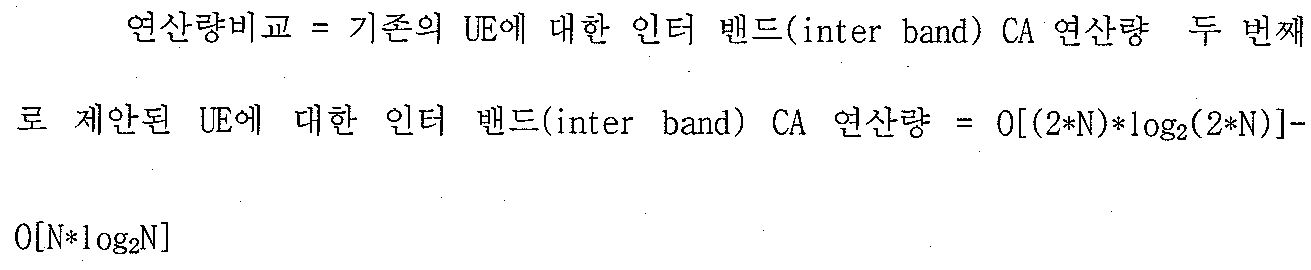
따라서, 역 고속 푸리에 변환(IFFT) 사이즈(size)의 증가에 따른 연산량의 증가가 추가로 발생되고, 이는 단순히 (2*N)*log2(2*N)-N*log2N 만큼의 연산량 증가를 가져 오게 되며, 이는 전체 시스템에서 미미한 연산량의 증가를 야기시키게 된다. 하지만 오버 샘플링(over sampling)을 고려했을 경우 연산량의 증가량은 없다.Thus, an increase in the amount of computation is caused by an increase in the inverse fast Fourier transform (IFFT) size, which simply results in an increase in the amount of computation by (2 * N) * log2 (2 * N) -N * log2N. This will cause a slight increase in the amount of computation in the overall system. However, there is no increase in computation when considering over sampling.
즉, 도 10의 구조는 인터 밴드(inter-band) CA를 지원하는 컴포넌트 캐리어(component carrier)의 수가 증가함에 따라 역 고속 푸리에 변환(IFFT) 블록(block) 수도 함께 증가하게 되어 도 6에서 제시한 구조에 비해 많은 연산량의 감소를 얻을 수 있는 구조는 아니지만, 인터 밴드 또는 인트라 밴드(intra/inter-band) CA를 동시에 간단한 구조로 지원할 수 있는 구조이다. That is, the structure of FIG. 10 increases the number of inverse fast Fourier transform (IFFT) blocks as the number of component carriers supporting inter-band CA increases. Although it is not a structure that can reduce a large amount of calculation compared to the structure, it is a structure that can simultaneously support interband or intra / inter-band CA as a simple structure.
도 10의 구조는 인트라 밴드(intra-band) CA를 지원 할 경우 오버 샘플링 비율(over-sampling rate)을 기존의 OFDM 시스템(system)을 지원하는 베이스 밴드(baseband) 구조보다 더 높게 할 수 있으므로 이에 대한 장점이 존재 할 수 있다.In the structure of FIG. 10, an over-sampling rate may be higher than a baseband structure supporting an existing OFDM system when supporting an intra-band CA. There may be an advantage.
도 11의 UE의 베이스 밴드부는 정보 비트(information bits)부 (100, 110), 코딩 및 변조(coding and modulation)부 (103, 113), 변환 프리코더(transform precoder)부(105, 115), 자원 요소 매핑(resource mapping)부(107, 117), 신호 결합기(combiner)(120), 역 고속 푸리에 변환(IFFT)부(210, 211), CP 첨가(add)부(300), 스위치(switch)(405, 407, 409), 저역 필터(low pass filter)(600, 610), RF 체인(chain)(700, 710), 듀플렉서(duplexer)(800, 810), 다이플렉서(diplexer)(900) 그리고 안테나(antenna)(10) 등을 포함한다. The base band portion of the UE of FIG. 11 is an
도 11은 도 10의 구조에서 인트라 밴드(intra-band) CA를 지원할 경우, UE의 베이스 밴드(baseband) 구조를 나타낸 것으로써 역 고속 푸리에 변환(IFFT) 블록(210, 211) 중에서 사이즈가 큰 블록(211)을 사용하는 것을 특징으로 하며, 또한 동작 주파수(operating frequency)가 적용될 수 있는 RF 체인(chain)(700)을 선택하여 인트라 밴드(intra-band) CA를 지원할 수 있다. FIG. 11 illustrates a baseband structure of a UE when supporting an intra-band CA in the structure of FIG. 10, and shows a block having a larger size among inverse fast Fourier transform (IFFT) blocks 210 and 211. Characteristic 211 may be used, and an intra-band CA may be supported by selecting an
이하, 본 발명에 따른 단말(또는 UE)의 구성 및 기능을 설명한다.Hereinafter, the configuration and function of the terminal (or UE) according to the present invention.
본 발명에 따른 단말은, 장치(device)라고도 통용될 수 있으며, 도 4에서 도 11의 실시 예들을 구현할 수 있는 모든 단말을 포함한다. 즉, 본 발명에 따른 단말, 즉 장치는 상술한 본 발명의 기술적 사상을 구현할 수 있는 이동통신 단말기(예를 들면, 사용자 장치(UE), 휴대폰, 셀룰라폰, DMB폰, DVB-H폰, PDA 폰, 그리고 PTT폰 등등)와, 디지털 TV와, GPS 네비게이션와, 휴대용 게임기와, MP3와 그외 가전 제품 등등을 포함하는 포괄적인 의미이다. The terminal according to the present invention may be commonly used as a device and includes all terminals capable of implementing the embodiments of FIG. 4 to FIG. 11. That is, the terminal according to the present invention, that is, the device is a mobile communication terminal (for example, a user device (UE), a mobile phone, a cellular phone, a DMB phone, a DVB-H phone, a PDA) that can implement the above-described technical spirit of the present invention. Phone, and PTT phone, etc.), digital TV, GPS navigation, handheld game consoles, MP3 and other consumer electronics, and so on.
이하, 본 발명에 따른 단말의 구성 및 기능을 설명한다.Hereinafter, the configuration and function of the terminal according to the present invention.
본 발명에 따른 단말은 도 4에서 도 11의 실시 예를 구현하는 소프트웨어 또는 그 소프트웨어가 장착된 모듈을 포함한다. 이러한 모듈은, 단말의 일 구성요소로서, 처리부 또는 제어부라고 칭할 수도 있다. 본 발명에 따른 단말은, 상술한 본 발명의 기술적 특징을 실행하기 필요한 필수적인 하드웨어 및 소프트웨어 구성요소를 포함한다. The terminal according to the present invention includes software for implementing the embodiment of FIG. 4 to FIG. 11 or a module equipped with the software. Such a module may be referred to as a processor or a controller as one component of a terminal. The terminal according to the invention comprises the necessary hardware and software components necessary to carry out the technical features of the invention described above.
여기까지 설명된 본 발명에 따른 방법은 소프트웨어, 하드웨어, 또는 이들의 조합으로 구현될 수 있다. 예를 들어, 본 발명에 따른 방법은 저장 매체(예를 들어, 이동 단말기 내부 메모리, 플래쉬 메모리, 하드 디스크, 기타 등등)에 저장될 수 있고, 프로세서(예를 들어, 이동 단말기 내부 마이크로 프로세서)에 의해서 실행될 수 있는 소프트웨어 프로그램 내에 코드들 또는 명령어들로 구현될 수 있다. The method according to the invention described thus far can be implemented in software, hardware, or a combination thereof. For example, the method according to the present invention may be stored in a storage medium (eg, mobile terminal internal memory, flash memory, hard disk, etc.) and may be stored in a processor (eg, mobile terminal internal microprocessor). It may be implemented as codes or instructions in a software program that can be executed by.
이상과 같이 예시된 도면을 참조로 하여, 본 명세서에 개시된 적어도 하나의 실시예에 따른 장치 및 방법에 대해여 설명하였으나, 본 명세서는 본 명세서에 개시된 실시예와 도면에 의해 한정되지 않으며, 그 발명의 기술사상 범위 내에서 당업자에 의해 다양한 변형이 이루어질 수 있음은 물론이다. With reference to the drawings illustrated as above, the apparatus and method according to at least one embodiment disclosed herein has been described, but the present specification is not limited by the embodiments and drawings disclosed herein, the invention Of course, various modifications can be made by those skilled in the art within the scope of the technical idea.
상기와 같이 설명된 상호공존 시스템에서의 대표기기를 선출하는 방법은 상기 설명된 실시예들의 구성과 방법이 한정되게 적용될 수 있는 것이 아니라, 상기 실시예들은 다양한 변형이 이루어질 수 있도록 각 실시예들의 전부 또는 일부가 선택적으로 조합되어 구성될 수도 있다.The method of selecting a representative device in the mutual coexistence system described above is not limited to the configuration and method of the above-described embodiments, but the embodiments may be modified in various ways so that various modifications may be made. Or some may be selectively combined.
이상에서 본 명세서에 개시된 실시예들을 첨부된 도면들을 참조로 설명하였다.Embodiments disclosed herein have been described with reference to the accompanying drawings.
여기서, 본 명세서 및 청구범위에 사용된 용어나 단어는 통상적이거나 사전적인 의미로 한정해서 해석되어서는 아니 되며, 본 명세서에 개시된 기술적 사상에 부합하는 의미와 개념으로 해석되어야만 한다.Here, the terms or words used in the present specification and claims should not be construed as being limited to the ordinary or dictionary meanings, but should be interpreted as meanings and concepts corresponding to the technical spirit disclosed in the present specification.
따라서 본 명세서에 기재된 실시예와 도면에 도시된 구성은 본 명세서에 개시된 일 실시예에 불과할 뿐이고, 본 명세서에 개시된 기술적 사상을 모두 대변하는 것은 아니므로, 본 출원시점에 있어서 이들을 대체할 수 있는 다양한 균등물과 변형예들이 있을 수 있음을 이해하여야 한다.Therefore, the embodiments described in the present specification and the configuration shown in the drawings are only one embodiment disclosed in the present specification, and do not represent all the technical ideas disclosed in the present specification. It should be understood that there may be equivalents and variations.
100, 110: CC(Component Carrier)
103, 113: Coding & Modulation
105, 115: Transform Precoder
107, 117: Resource element mapping
120: Combiner
200: IFFT (Inverse Fast Fourier Transform) Block
210: Small IFFT (Inverse Fast Fourier Transform) Block
211: Large IFFT (Inverse Fast Fourier Transform) Block
220: IFFT (Inverse Fast Fourier Transform) Block with GB(Guard Band)
300, 310: CP (Cyclic Prefix)
400, 403, 405, 407: SW (Switch)
500, 510: Mixer
600, 610: LPF (Low Pass Filter)
700, 710: RF (Radio Frequency) chain
800, 810: Duplexer
900: Diplexer
10: Antenna100, 110: CC (Component Carrier)
103, 113: Coding & Modulation
105, 115: Transform Precoder
107, 117: Resource element mapping
120: Combiner
200: Inverse Fast Fourier Transform (IFFT) Block
210: Small IFFT (Inverse Fast Fourier Transform) Block
211: Large IFFT (Inverse Fast Fourier Transform) Block
220: Inverse Fast Fourier Transform (IFFT) Block with GB (Guard Band)
300, 310: CP (Cyclic Prefix)
400, 403, 405, 407: SW (Switch)
500, 510: Mixer
600, 610: LPF (Low Pass Filter)
700, 710: RF (Radio Frequency) chain
800, 810: Duplexer
900: Diplexer
10: Antenna
Claims (13)
상기 제 1 주파수 대역을 사용하는 경우, 상기 하나의 기적대역 및 상기 두 개의 RF 체인 중에서 상기 컴포넌트 캐리어 특성에 대응되는 적어도 하나의 RF 체인으로 스위칭 하는 단계;
를 포함하는 것을 특징으로 하는 무선 통신 시스템에서의 캐리어 집성 방법. Using one baseband and two RF chains in which two pieces of information are combined to aggregate two component carriers in a first frequency band and a second frequency band per antenna port; And
When using the first frequency band, switching to at least one RF chain corresponding to the component carrier characteristic among the one miracle band and the two RF chains;
Carrier aggregation method in a wireless communication system comprising a.
상기 제 1 주파수 대역을 사용하는 경우, 상기 제 2 기저 대역의 정보를 상기 제 1 기저 대역의 정보에 결합한 하나의 기저 대역과 상기 제 1 RF 체인과 상기 제 2 RF 체인 중에서 컴포넌트 캐리어 특성에 대응되는 적어도 하나의 RF 체인으로 스위칭 하는 단계;
를 포함하는 것을 특징으로 하는 무선 통신 시스템에서의 캐리어 집성 방법. Using a first base band and a second base band and a first RF chain and a second RF chain to aggregate two component carriers in a first frequency band and a second frequency band per antenna port; And
When using the first frequency band, one baseband combining the information of the second baseband with the information of the first baseband, and corresponding to component carrier characteristics among the first RF chain and the second RF chain. Switching to at least one RF chain;
Carrier aggregation method in a wireless communication system comprising a.
상기 제 2 주파수 대역을 사용하는 경우, 상기 기저 대역 개수 만큼의 역 고속 푸리에 변환 (IFFT) 블록을 이용하여 각 기저 대역의 정보를 처리하는 것을 특징으로 하는 무선 통신 시스템에서의 캐리어 집성 방법.7. The method of claim 6, wherein when using the first frequency band, the first baseband uses oversampling and uses one inverse fast Fourier transform (IFFT) block to provide information about the first baseband information. 2 processes the signal combining the baseband information, or
In the case of using the second frequency band, the carrier aggregation method in the wireless communication system characterized by processing the information of each baseband by using an inverse fast Fourier transform (IFFT) block as the number of basebands.
상기 제 2 주파수 대역을 사용하는 경우에는 상기 제 1 역 고속 푸리에 변환블록 및 제 2 역 고속 푸리에 변환 블록을 사용하는 것을 특징으로 하되,
상기 제 1 역 고속 푸리에 변환 블록은 상기 제 2 역 고속 푸리에 변환 블록 보다 큰 사이즈를 가지는 것을 특징으로 하는 무선 통신 시스템에서의 캐리어 집성 방법.10. The apparatus of claim 9, wherein the inverse fast Fourier transform block comprises a first inverse fast Fourier transform block and a second inverse fast Fourier transform block. To process a signal in which the information of the first baseband is combined with the information of the second baseband, or
In the case of using the second frequency band, the first inverse fast Fourier transform block and the second inverse fast Fourier transform block are used.
And the first inverse fast Fourier transform block has a larger size than the second inverse fast Fourier transform block.
상기 제 1 주파수 대역을 사용하는 경우, 상기 하나의 기적대역 및 상기 두 개의 RF 체인 중에서 상기 컴포넌트 캐리어 특성에 대응되는 적어도 하나의 RF 체인으로 스위칭 하는 제어부;
를 포함하는 것을 특징으로 하는 무선 통신 시스템에서의 캐리어 집성 장치. Using one baseband and two RF chains in which two pieces of information are combined to aggregate two component carriers in a first frequency band and a second frequency band per antenna port,
A control unit for switching to at least one RF chain corresponding to the component carrier characteristics among the one miracle band and the two RF chains when using the first frequency band;
Carrier aggregation device in a wireless communication system comprising a.
상기 제 1 주파수 대역을 사용하는 경우, 상기 제 2 기저 대역의 정보를 상기 제 1 기저 대역의 정보에 결합한 하나의 기저 대역과 상기 제 1 RF 체인과 상기 제 2 RF 체인 중에서 컴포넌트 캐리어 특성에 대응되는 적어도 하나의 RF 체인으로 스위칭 하는 제어부;
를 포함하는 것을 특징으로 하는 무선 통신 시스템에서의 캐리어 집성 장치.Using a first baseband and a second baseband and a first RF chain and a second RF chain to aggregate two component carriers in a first frequency band and a second frequency band per antenna port,
When using the first frequency band, one baseband combining the information of the second baseband with the information of the first baseband, and corresponding to component carrier characteristics among the first RF chain and the second RF chain. A controller for switching to at least one RF chain;
Carrier aggregation device in a wireless communication system comprising a.
Priority Applications (2)
| Application Number | Priority Date | Filing Date | Title |
|---|---|---|---|
| PCT/KR2011/004932 WO2012039541A1 (en) | 2010-09-20 | 2011-07-06 | Method and apparatus for carrier aggregation in wireless communication system |
| US13/823,670 US8792830B2 (en) | 2010-09-20 | 2011-07-06 | Method and apparatus for carrier aggregation in wireless communication system |
Applications Claiming Priority (2)
| Application Number | Priority Date | Filing Date | Title |
|---|---|---|---|
| US38432610P | 2010-09-20 | 2010-09-20 | |
| US61/384,326 | 2010-09-20 |
Publications (1)
| Publication Number | Publication Date |
|---|---|
| KR20120030919A true KR20120030919A (en) | 2012-03-29 |
Family
ID=46134726
Family Applications (1)
| Application Number | Title | Priority Date | Filing Date |
|---|---|---|---|
| KR1020110016200A KR20120030919A (en) | 2010-09-20 | 2011-02-23 | Method and apparatus for carrier aggregation in wireless communication system |
Country Status (2)
| Country | Link |
|---|---|
| US (1) | US8792830B2 (en) |
| KR (1) | KR20120030919A (en) |
Cited By (5)
| Publication number | Priority date | Publication date | Assignee | Title |
|---|---|---|---|---|
| CN103427890A (en) * | 2012-05-24 | 2013-12-04 | 华为技术有限公司 | Method for transmitting information, sending end device and receiving end device |
| WO2013184670A1 (en) * | 2012-06-09 | 2013-12-12 | Apple Inc. | Rf chain management in a carrier aggregation capable wireless communication device |
| WO2015060591A1 (en) * | 2013-10-21 | 2015-04-30 | Samsung Electronics Co., Ltd. | Front end configurations supporting inter-band carrier aggregation |
| KR20170043006A (en) | 2015-10-12 | 2017-04-20 | 주식회사 엘지유플러스 | Apparatus and method for retransmitting communication packet |
| WO2020036363A1 (en) * | 2018-08-16 | 2020-02-20 | 삼성전자 주식회사 | Method for changing ground unit of antenna on basis of data throughput speed estimation, and electronic device therefor |
Families Citing this family (8)
| Publication number | Priority date | Publication date | Assignee | Title |
|---|---|---|---|---|
| US7885176B2 (en) | 2007-06-01 | 2011-02-08 | Samsung Electronics Co., Ltd. | Methods and apparatus for mapping modulation symbols to resources in OFDM systems |
| DK2486692T3 (en) * | 2009-10-05 | 2018-03-12 | Ericsson Telefon Ab L M | PUCCH resource allocation for carrier aggregation in LTE-advanced |
| US9277398B2 (en) * | 2011-08-22 | 2016-03-01 | Sharp Kabushiki Kaisha | User equipment capability signaling |
| EP2721762A1 (en) * | 2012-03-15 | 2014-04-23 | Broadcom Corporation | Reducing complexity and power consumption in cellular networks with carrier aggregation |
| US9287901B2 (en) * | 2013-09-20 | 2016-03-15 | Broadcom Corporation | Receiver for carrier aggregation |
| CN106716862A (en) * | 2014-10-29 | 2017-05-24 | 富士通株式会社 | Codebook determination method and apparatus, and communication system |
| US9871646B2 (en) | 2015-09-30 | 2018-01-16 | Microsoft Technology Licensing, Llc | Front-end circuitry for multiband frequency management |
| US20190053237A1 (en) * | 2017-08-11 | 2019-02-14 | Qualcomm Incorporated | Carrier switching for multiple carriers using the same components of a component path |
Family Cites Families (7)
| Publication number | Priority date | Publication date | Assignee | Title |
|---|---|---|---|---|
| US6687307B1 (en) * | 2000-02-24 | 2004-02-03 | Cisco Technology, Inc | Low memory and low latency cyclic prefix addition |
| JP3997890B2 (en) * | 2001-11-13 | 2007-10-24 | 松下電器産業株式会社 | Transmission method and transmission apparatus |
| US7418047B2 (en) * | 2004-02-25 | 2008-08-26 | Matsushita Electric Industrial Co., Ltd. | Communication apparatus using a plurality of modulation schemes and transmission apparatus composing such communication apparatus |
| US7848458B2 (en) * | 2005-02-18 | 2010-12-07 | Mitsubishi Electric Corporation | Communication apparatus |
| KR101089838B1 (en) | 2008-08-13 | 2011-12-05 | 한국전자통신연구원 | Communication system of using carrier aggregation and base station and terminl included in the communication system |
| KR101737831B1 (en) | 2009-02-02 | 2017-05-19 | 엘지전자 주식회사 | Method of mapping transport sequences to component carriers in a wireless communication system |
| US8583170B2 (en) | 2009-02-16 | 2013-11-12 | Telefonaktiebolaget Lm Ericsson (Publ) | Multi-band aggregated spectrum receiver employing frequency source reuse |
-
2011
- 2011-02-23 KR KR1020110016200A patent/KR20120030919A/en not_active Application Discontinuation
- 2011-07-06 US US13/823,670 patent/US8792830B2/en active Active
Cited By (9)
| Publication number | Priority date | Publication date | Assignee | Title |
|---|---|---|---|---|
| CN103427890A (en) * | 2012-05-24 | 2013-12-04 | 华为技术有限公司 | Method for transmitting information, sending end device and receiving end device |
| WO2013184670A1 (en) * | 2012-06-09 | 2013-12-12 | Apple Inc. | Rf chain management in a carrier aggregation capable wireless communication device |
| CN104365038A (en) * | 2012-06-09 | 2015-02-18 | 苹果公司 | RF chain management in a carrier aggregation capable wireless communication device |
| US9119211B2 (en) | 2012-06-09 | 2015-08-25 | Apple Inc. | RF chain management in a carrier aggregation capable wireless communication device |
| WO2015060591A1 (en) * | 2013-10-21 | 2015-04-30 | Samsung Electronics Co., Ltd. | Front end configurations supporting inter-band carrier aggregation |
| KR20170043006A (en) | 2015-10-12 | 2017-04-20 | 주식회사 엘지유플러스 | Apparatus and method for retransmitting communication packet |
| WO2020036363A1 (en) * | 2018-08-16 | 2020-02-20 | 삼성전자 주식회사 | Method for changing ground unit of antenna on basis of data throughput speed estimation, and electronic device therefor |
| KR20200020197A (en) * | 2018-08-16 | 2020-02-26 | 삼성전자주식회사 | Antenna switch changing method based on data processing speed estimation and electronic device thereof |
| US11901649B2 (en) | 2018-08-16 | 2024-02-13 | Samsung Electronics Co., Ltd. | Method for changing ground unit of antenna on basis of data throughput speed estimation, and electronic device therefor |
Also Published As
| Publication number | Publication date |
|---|---|
| US8792830B2 (en) | 2014-07-29 |
| US20130177091A1 (en) | 2013-07-11 |
Similar Documents
| Publication | Publication Date | Title |
|---|---|---|
| KR20120030919A (en) | Method and apparatus for carrier aggregation in wireless communication system | |
| US11469798B2 (en) | Apparatus and methods for radio frequency front-ends | |
| EP2919391B1 (en) | Radio frequency channel for carrier aggregation | |
| US10687323B2 (en) | Beamformed physical downlink control channel | |
| KR102032524B1 (en) | Single―chip signal splitting carrier aggregation receiver architecture | |
| US11509413B2 (en) | Apparatus, system and method of an orthogonal frequency-division multiplexing (OFDM) transmission over a wide bandwidth | |
| KR102572773B1 (en) | Simplified multi-band/carrier carrier aggregation radio frequency front-end based on frequency-shifted antennas | |
| US11159194B2 (en) | Front end systems with switched termination for enhanced intermodulation distortion performance | |
| US9755767B2 (en) | Mechanism to measure, report, and allocate a highest possible rank for each cell in a carrier aggregation (CA) mode receiver-limited user equipment (UE) | |
| US11601144B2 (en) | Broadband architectures for radio frequency front-ends | |
| US11863473B2 (en) | Coding over multiple resource units (RU) in extremely high throughput (EHT) systems | |
| US11671122B2 (en) | Filter reuse in radio frequency front-ends | |
| US20210211145A1 (en) | Ultrahigh band architecture for radio frequency front-ends | |
| CN113938142A (en) | Dual connection power amplifier system | |
| US20220182803A1 (en) | Apparatus, system and method of communicating a next generation vehicular (ngv) physical layer (phy) protocol data unit (ppdu) | |
| WO2017131810A1 (en) | System and method for system information transmission in stand-alone mmwave systems | |
| US20210266121A1 (en) | Apparatus, system, and method of communicating an extremely high throughput (eht) physical layer (phy) protocol data unit (ppdu) | |
| EP3902178A1 (en) | Capacity configuration method and apparatus | |
| CN110224704B (en) | Radio frequency system and base station equipment | |
| WO2012039541A1 (en) | Method and apparatus for carrier aggregation in wireless communication system | |
| US20230308119A1 (en) | Connectivity architecture for antenna switching | |
| US20240097756A1 (en) | Front-end systems bypassing transmit band filter for antenna switching | |
| US20240146339A1 (en) | Radio frequency front end system with dual connectivity support | |
| US20230318634A1 (en) | Systems and methods for reducing loading in antenna switch module multiplexing | |
| US20240154633A1 (en) | Multiple concurrent antenna configurations for enhanced transmitter power capability |
Legal Events
| Date | Code | Title | Description |
|---|---|---|---|
| A201 | Request for examination | ||
| E902 | Notification of reason for refusal | ||
| E601 | Decision to refuse application |