KR20120009640A - Antisubmarine warning system for the shallow sea - Google Patents
Antisubmarine warning system for the shallow sea Download PDFInfo
- Publication number
- KR20120009640A KR20120009640A KR1020100069744A KR20100069744A KR20120009640A KR 20120009640 A KR20120009640 A KR 20120009640A KR 1020100069744 A KR1020100069744 A KR 1020100069744A KR 20100069744 A KR20100069744 A KR 20100069744A KR 20120009640 A KR20120009640 A KR 20120009640A
- Authority
- KR
- South Korea
- Prior art keywords
- sonar
- ultrasonic
- node
- control
- submarine
- Prior art date
Links
Images


Classifications
-
- B—PERFORMING OPERATIONS; TRANSPORTING
- B60—VEHICLES IN GENERAL
- B60R—VEHICLES, VEHICLE FITTINGS, OR VEHICLE PARTS, NOT OTHERWISE PROVIDED FOR
- B60R21/00—Arrangements or fittings on vehicles for protecting or preventing injuries to occupants or pedestrians in case of accidents or other traffic risks
- B60R21/01—Electrical circuits for triggering passive safety arrangements, e.g. airbags, safety belt tighteners, in case of vehicle accidents or impending vehicle accidents
- B60R21/013—Electrical circuits for triggering passive safety arrangements, e.g. airbags, safety belt tighteners, in case of vehicle accidents or impending vehicle accidents including means for detecting collisions, impending collisions or roll-over
- B60R21/0136—Electrical circuits for triggering passive safety arrangements, e.g. airbags, safety belt tighteners, in case of vehicle accidents or impending vehicle accidents including means for detecting collisions, impending collisions or roll-over responsive to actual contact with an obstacle, e.g. to vehicle deformation, bumper displacement or bumper velocity relative to the vehicle
-
- G—PHYSICS
- G01—MEASURING; TESTING
- G01S—RADIO DIRECTION-FINDING; RADIO NAVIGATION; DETERMINING DISTANCE OR VELOCITY BY USE OF RADIO WAVES; LOCATING OR PRESENCE-DETECTING BY USE OF THE REFLECTION OR RERADIATION OF RADIO WAVES; ANALOGOUS ARRANGEMENTS USING OTHER WAVES
- G01S13/00—Systems using the reflection or reradiation of radio waves, e.g. radar systems; Analogous systems using reflection or reradiation of waves whose nature or wavelength is irrelevant or unspecified
- G01S13/74—Systems using reradiation of radio waves, e.g. secondary radar systems; Analogous systems
- G01S13/76—Systems using reradiation of radio waves, e.g. secondary radar systems; Analogous systems wherein pulse-type signals are transmitted
- G01S13/78—Systems using reradiation of radio waves, e.g. secondary radar systems; Analogous systems wherein pulse-type signals are transmitted discriminating between different kinds of targets, e.g. IFF-radar, i.e. identification of friend or foe
-
- G—PHYSICS
- G01—MEASURING; TESTING
- G01S—RADIO DIRECTION-FINDING; RADIO NAVIGATION; DETERMINING DISTANCE OR VELOCITY BY USE OF RADIO WAVES; LOCATING OR PRESENCE-DETECTING BY USE OF THE REFLECTION OR RERADIATION OF RADIO WAVES; ANALOGOUS ARRANGEMENTS USING OTHER WAVES
- G01S15/00—Systems using the reflection or reradiation of acoustic waves, e.g. sonar systems
- G01S15/87—Combinations of sonar systems
-
- G—PHYSICS
- G01—MEASURING; TESTING
- G01S—RADIO DIRECTION-FINDING; RADIO NAVIGATION; DETERMINING DISTANCE OR VELOCITY BY USE OF RADIO WAVES; LOCATING OR PRESENCE-DETECTING BY USE OF THE REFLECTION OR RERADIATION OF RADIO WAVES; ANALOGOUS ARRANGEMENTS USING OTHER WAVES
- G01S15/00—Systems using the reflection or reradiation of acoustic waves, e.g. sonar systems
- G01S15/88—Sonar systems specially adapted for specific applications
Landscapes
- Engineering & Computer Science (AREA)
- Radar, Positioning & Navigation (AREA)
- Remote Sensing (AREA)
- Physics & Mathematics (AREA)
- Computer Networks & Wireless Communication (AREA)
- General Physics & Mathematics (AREA)
- Mechanical Engineering (AREA)
- Acoustics & Sound (AREA)
- Measurement Of Velocity Or Position Using Acoustic Or Ultrasonic Waves (AREA)
Abstract
In the present invention, in the West Sea area where the water depth is low within 100M, and there is a problem with the shadow zone due to the water temperature difference, it is difficult to detect the submarine in the ship far away in the horizontal direction, it detects and strikes the submarine with accurate, safe and high detection rate at the early stage of penetration. We also wanted to implement a system that could identify the pia. In addition, it was intended to realize that the twine is not damaged by fishing nets, fish shocks, and typhoons caused by typhoons. Electricity for sensors and control devices can be self-supported. In addition, the information detected by the sensor can be quickly delivered from the remote ship and control center, and control commands issued from the ship and control center can be transmitted to the control device in real time. The aim was to detect and respond to submarines safely and quickly.
For improved detection accuracy and safe and fast detection and response, SONAR is placed under the sea to be monitored without being trapped or towed, allowing only near objects to be detected, and adding SONAR again when it is out of range. In addition, the FALSE ALRAM is very small and the accuracy is very high.
In order to reduce the shadow area problem, SONAR installed in a network structure in the supervised sea area gives unique ultrasonic pulses distinguished by codes, allowing multiple SONARs to operate simultaneously, even if one SONAR causes a shadow area problem. Can detect the reflected wave normally. In addition, the sound field problem is further improved by allowing pulses emitted by one SONAR to be identified by the other SONAR.
In order to identify the enemy and allies, we implemented an ultrasonic identification device that notifies allies in response to SONAR, and the PIA identification process operates automatically and secretly using the SONAR characteristic, exposing the information to the friendly position and PIA identification intention. This was to minimize.
In order to prevent the twine from being damaged by fishing nets, fish shocks, and strong winds caused by typhoons, a method was devised in which each node did not use cables for power, communication, and support. First of all, in order not to use the power cable, a small generator using a tidal current that can adequately supply the power required by each node is implemented. In order not to use a communication cable, an ultrasonic transceiver and a router were installed to relay transmissions, and wireless transmissions could be made to ships and control centers in remote areas. The protection net is applied to protect the rotating body, the sensor, the control device, and the communication device for the generation of electricity. The protection net is implemented in a hemispherical shape of the mosquito net structure to reduce the power generation efficiency and to be less damaged by the external force. In order to eliminate the supporting cable, a small sized node and a fixed device suitable for various sea floor installations were implemented. Also, a remote control device that can be installed and repaired remotely in a ship was implemented to quickly and easily install and maintain the sea.
In addition, sensors, control devices, and detonators are networked on the floor, so that detected information can be quickly delivered to traps and control centers, and control commands issued by judgment are transmitted in real time to the control and detonator located at the point. In this way, ships and control centers can detect and respond to submarines safely and quickly and accurately.
Therefore, the present invention is a submarine submarine early warning system capable of detecting and responding to submarine in early detection quickly and accurately and stably even in a difficult situation such as the West Sea, which has a large water temperature difference, a large change in algae, and active fishing operations. Would be greatly helpful. In addition, it can be constructed at a relatively low cost compared to expensive surveillance systems such as SOSUS, and it can be relatively reduced in maintenance cost and time.

Description
The present invention relates to a system for monitoring and guarding submarines penetrating into the sea.
Due to the sinking of the Cheonan in the West Sea, new defenses against ships are urgently needed. Especially in seas with low depths and rapidly changing tides, such as the West Sea, it is not enough to defend with existing radar and sonar bays. There is SOSUS that detects submarines by detecting ultrasonic waves applied to all seas, including deep seas. However, twin fishing vessels are operated and the western sea, which is affected by typhoons, is damaged due to damage to devices, low depth, and shadow area. Inadequate Therefore, there is an urgent need for a submarine submarine boundary system suitable for bordering low-depth oceans such as the West Sea.
In the present invention, in the West Sea region where the water depth is low within 100M, and there is a problem of the shadow zone due to the water temperature difference, and it is difficult to detect the submarine in a distant ship in the horizontal direction, it detects the submarine with accurate, safe and high detection rate at the beginning of penetration. We wanted to implement a system that could strike and identify pia.
In addition, it was intended to realize that the twine is not damaged by fishing nets, fish shocks, and typhoons caused by typhoons. Electricity for sensors and control devices can be self-supported.
In addition, the information detected by the sensor can be quickly delivered from the remote ship and control center, and control commands issued from the ship and control center can be transmitted to the control device in real time. The aim was to detect and respond to submarines safely and quickly.
For improved detection accuracy and safe and fast detection and response, SONAR is placed under the sea to be monitored without being attached or towed to a trap, allowing SONAR to detect only objects in close proximity and another point outside the detection range. The SONAR is further installed, and relay transmission is performed between the SONARs, so that the FALSE ALRAM is very small, the accuracy is very high, and the boundary system can be detected quickly at the early stage of penetration.
Also, in order to reduce the shadow area problem, the SONAR installed in the network structure in the monitoring area has a unique ultrasonic pulse distinguished by a code, so that multiple SONARs can operate at the same time, even if one SONAR has a shadow area problem. SONAR is able to detect the reflected wave normally. In addition, the sound range problem is doubled by making the pulse sent by one SONAR distinguishable by the other SONAR.
In addition, in order to identify the enemy and allies, we implemented an ultrasonic identification device that notifies allies in response to SONAR, and the PIA identification process operates automatically and secretly using the SONAR characteristics, so that the information based on the location and PIA identification intention of the allies is implemented. Exposure was minimized.
Also, in order to prevent the nodes from being damaged by the twine fishing nets, the impact of the fish, the strong winds caused by the typhoon, etc., each node was derived a method that does not use cables for power, communication, and support. First of all, in order not to use the power cable, a small generator using a tidal current that can adequately supply the power required by each node is implemented. In order not to use a communication cable, an ultrasonic transceiver and a router were installed to relay transmissions, and wireless transmissions could be made to ships and control centers in remote areas. The protection net is applied to protect the rotating body, the sensor, the control device, and the communication device for the generation of electricity. The protection net is implemented in a hemispherical shape of the mosquito net structure to reduce the power generation efficiency and to be less damaged by the external force. In addition, to eliminate the support cable, a miniaturized node and a separate fixing device suitable for various sea floor installations are implemented. Also, a remote control device that can be installed and repaired remotely from a ship is implemented for quick and simple installation and maintenance.
In addition, sensors, control devices, and detonators are networked on the floor so that detected information can be quickly delivered to the ships and control centers. It was designed to ensure that ships and control centers could detect and respond to submarines safely and quickly.
Currently, the new sea defense system is urgently needed due to the sinking of the Cheonan in the West Sea, but the West Sea has a lot of shade zone problems due to the rapid change of algae, large water temperature difference, and very low sea depth. It is not enough to detect only the traps by using it, and even if it is detected, if the detection is made in close proximity to the trap, there is not enough time to respond.
Accordingly, the present invention is a submarine submarine early warning system capable of detecting and responding to submarine intrusion early and accurately in a difficult situation such as the West Sea, which has a large water temperature difference, a large tide change, and active fishing vessels. Would be greatly helpful. In addition, it can be constructed at a relatively low cost compared to expensive surveillance systems such as SOSUS, and it can be relatively reduced in maintenance cost and time.
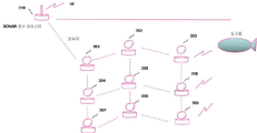
1 is a conceptual diagram of the present invention, a figure showing a state in which a submarine is detected using a sensor in the boundary area, and the detection information is quickly sent to the trap.
2 is a diagram illustrating transmission of information detected by relay transmission between nodes.
3 is a diagram illustrating a method of assigning a unique code to SONAR.
4 is a diagram illustrating a method for pia identification.
5 is a diagram illustrating a method of reusing a cell frequency for a SONAR sensor.
6 is a diagram showing a state in which the mobile route of the submarine is grasped by arranging nodes in a net form.
7 is a diagram showing a state of obtaining position information through the ship.
8 is a diagram illustrating a state of obtaining location information through neighboring nodes.
9 is a block diagram of a node.
10 is a block diagram for distributed SONAR.
11 is a block diagram of a reception processing unit of a distributed SONAR.
12 is a block diagram of an ultrasonic communicator.
13 is a block diagram of a pia identification device.
14 is a block diagram of a wireless remote blasting apparatus.
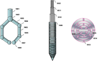
15 is a view showing a small generator using a tidal current.
16 is a diagram showing the arrangement of the ultrasonic vibrator using the protective net and the protective net.
FIG. 17 is a diagram showing a node installed remotely using an unmanned submersible.
18 is a view showing the body of the unmanned submersible.
19 shows a robot hand and a support leg of an unmanned submersible.
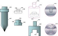
Figure 20 is a view showing the jig for fixing the fixture and the fixture for installation.
Figure 21 is a view showing a jig for fixing the fixing device and the fixing device for rock installation.
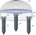
22 is a view showing a node fixed by using a lock installation device.
Due to the sinking of the Cheonan in the West Sea, new defenses against ships are urgently needed. Especially in seas with low water depths and rapidly changing tides, such as the West Sea, it is not enough to use existing radars and existing sonar bays. It is applied to all seas including the deep sea, and there is SOSUS which detects the submarine by ultrasonic waves, but it is not suitable for the west sea, which is a twin sea fishing operation and the typhoon-affected sea. Thus, there is a need for a submarine submarine surveillance system suitable for alerting low-depth oceans such as the West Sea.
Therefore, in the present invention, in order to improve detection accuracy and safe and fast detection and response, the SONAR is placed under the sea of the sea area to be monitored without being attached or towed to the trap, and the SONAR allows the detection of only a short range of objects and the detection range. At the point of departure, another SONAR was installed, and relay transmission was made between the sensors, so that the FALSE ALRAM was very small, the accuracy was very high, and the boundary system was able to detect quickly at the beginning of penetration.
Also, in order to reduce the shadow area problem, the SONAR installed in the network structure in the monitoring area has a unique ultrasonic pulse distinguished by a code, so that multiple SONARs can operate at the same time, even if one SONAR has a shadow area problem. SONAR is able to detect the reflected wave normally. In addition, the pulse region sent out by one SONAR can be identified by the other SONAR, which doubles the range problem.
In addition, in order to identify the enemy and allies, we implemented an ultrasonic identification device that notifies allies in response to SONAR, and the PIA identification process operates automatically and secretly using the SONAR characteristics, so that the information based on the location and PIA identification intention of the allies is implemented. Exposure was minimized.
In addition, in order to prevent damage to the nets of fishing boats, fish shocks, and strong winds caused by typhoons, a method was adopted to prevent the use of power, communication, and cables for each node. First of all, in order not to use the power cable, a small generator using a tidal current that can adequately supply the power required by each node is implemented. In order not to use a communication cable, an ultrasonic transceiver and a router were installed so that the relay could be wirelessly transmitted, and an RF could be sent to a ship and a control center over a long distance. In addition, the protection net is applied to protect the rotating body, sensor, control device, and communication device for electricity generation. The protection net is implemented in the hemispherical shape of the mosquito net structure to reduce the power generation efficiency and to be less damaged by external force. In addition, to eliminate the support cable, the node was miniaturized and a fixed device suitable for various sea floor installations was implemented.
In addition, in order to make installation and maintenance quick and simple, a remote control device that can be installed and repaired remotely in a ship is implemented.
It also connects the detonator to nodes in the network, allowing control commands issued from remote locations to be transmitted in real time to the control and detonator located at the point, so that ships and control centers can detect and respond to submarines safely and quickly and accurately. It was. If necessary, the detonation function may be added to the node configuring the network, or may be implemented as a separate node having only the detonation function without a sensor.
First, more detail for detection accuracy and safe and fast detection and response are as follows. A number of nodes equipped with sensors were installed at the boundary area, and an ultrasonic network was constructed to transfer information between nodes. In order to realize the network, each node has a built-in router and an ultrasonic transceiver to relay data in the AD-HOC relay method, and the CSMA / CD protocol is applied so that many nodes can exchange data by sharing a limited frequency band. In addition, we have derived a protocol for allocating time zones and bands so that both sonar and data communication modems can use ultrasound. In addition, at the point of contact with the land, there is an RF relay hub that converts the data received by ultrasonic waves into RF and transmits the information detected by the sensor to the ship and control center at a remote location. Control commands issued in real time are sent to the correct control device, allowing the ships and control centers to detect and respond to submarines safely and quickly.
The shadow area problem was solved in two ways. The first is to distribute the SONAR in several places, and the second is to identify one SONAR signal in another SONAR receiver. The first method is to distribute SONAR in several places in the sea area where penetration is expected. SONARs distributed in different places emit ultrasonic waves to different routes so that even if submarines are not detected due to shading problems at one point, submarines can be detected in other SONARs, improving shadow area problems. That's how. In the second method, as in the first method, SONAR is distributed in several places in the sea where the penetration is expected, but each emits an identifiable ultrasonic signal and can be received by other receivers. 3 is a diagram illustrating an identification code. The identification code and timing information transmission are made through data communication with each other, or injected at the time of installation. As mentioned above, the two methods are double applied to improve the shadow area problem.
Each SONAR uses a coded pulse and assigns a code set having a specific frequency at a specific time in the pulse as shown in FIG. 3, and the assigned code sets do not influence each other, and signals transmitted from one SONAR are different from each other. Signals can also be identified in the SONAR, so that even if the reflected signal does not return and reaches another SONAR, the distance and position of the object can be known, thereby improving shadowing problems and detection probability. The
The
Detailed description for PIA identification is as follows. SONAR sends out ultrasonic pulses for PIA identification, and virtual echoes for identification on friendly submarines. Therefore, the reception pulse shape is as shown in FIG. In FIG. 4, 401 is a sending pulse, 402 is a reflection wave in a friendly submarine, and 403 is a response pulse sent by a friendly team for PIA identification. The SONAR has the same function as the existing SONAR, but additionally has a function of intentionally changing a transmission period and a function of finding a virtual reflection pulse by checking a time interval of reflected waves. The virtual reflective wave transmitting device is installed in a friendly submarine or a trap, receives a SONAR pulse, and plays a role in generating a virtual reflected wave when the intention to confirm the friendlyness in the SONAR is confirmed. The virtual reflected wave is sent out after a predetermined time delay based on the input pulse. Predetermined time delays are coded to keep them from being exposed. In addition, using the above code, if RANDOM is changed in a predetermined area but a delay is generated by using a pseudo random number generated by the correct order, it will be more difficult to decode at the right side.
Figure 4 (b) is a diagram showing the output pulse waveform of the SONAR with the PIA identification function. SONAR pulses are sent out at regular intervals as shown in the
The content for frequency reuse is explained in more detail as follows. 5 illustrates a concept of dividing a frequency and a code into cell units so that nodes 501, 502, 503, 504, 505, 506, 507, 508, 509 can simultaneously use a limited frequency resource. As shown in FIG. 5, two methods are available when allocating resources by dividing sectors in a cell form. In the first method, only one node transmits a pulse (coded pulse having a specific set of frequencies at a specific time in a pulse) in one
Detailed description for identifying the route of movement of the infiltration submarine is as follows. 6 is a diagram showing a submarine detection situation when the nodes are installed in the net structure in the sea. When the submarine is detected at the
The method of providing location information to a node is as follows. The node has a location information acquisition device composed of an ultrasonic communicator and a CPU, and the ship has a location information transmission device composed of an ultrasonic communicator and a CPU, and the ship has data indicating the received GPS information and a timestamp indicating the transmission start point. To transmit to the node installed in the sea, the process is repeated three or more times as the ship moves as shown in FIG.
In order to determine the location by trigonometry, only the location information of three points in different locations is required, but when ultrasonic waves progress in the sea, the phenomenon of refraction due to the gradient of water temperature difference may occur. It sends data including the location information and timestamp of the point, and the location information acquisition device checks the timestamp and the arrival time and uses the location information of the three points in the shortest path. This is because the ultrasound signal received in the shortest path is the path with the least refraction in the transmission process.
In the position information acquisition device installed in the sea, using the position information and time information sent from the three points determined in the above process and trigonometric calculation, it is possible to obtain the position information of the currently installed point. The GPS information uses DGPS data to increase location accuracy.
When three or more nodes are installed in the periphery according to the above procedure, as shown in FIG. Therefore, the remaining additional devices do not need the help of the location information transmission device installed on the ship. Also, when the node wants to update the location information when there is a position movement by external force after installation, the three nearby devices Location information can be obtained using the information of the above nodes.
Here's how to install a node: As shown in FIG. 17, a
Node In addition to sensors, control and detonator devices can be connected to add an electrical primer, a sensing sensor, a control circuit, a drive circuit, a data transceiver, and a self-generator to mines for remote hitting. . It also sends a signal from the mine's detector to the trap and control center so that it can be blown only when the pia is identified and determined to be necessary. The ships are stationed in safe waters, and the detection and blasting devices are placed in permeable areas to determine whether or not intercepting vessels and submarines are intercepted by the detectors so that they can be blown up remotely if necessary, providing a stable defense system at sea. To build.
The following is a detailed description of the operation and function with the configuration diagram and block diagram for the present invention. 1 is a conceptual diagram of the present invention installed at the bottom of the sea, the
2 is a diagram showing each
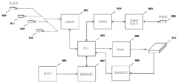
9 is a block diagram of a node. As shown in FIG. 9, the node includes a
The
The
The
The
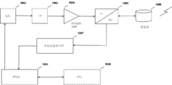
10 is a block diagram of a SONAR, where SONAR is an
The
The
The transmitted ultrasonic pulse is reflected by the object in the water and returned. The reflected pulse is received by the
When it is confirmed that the pulse is sent through the above process, the distance to the object is calculated using the pulse transmission time and the reflected wave arrival time. If the other SONAR is identified as a pulse sent, the distance from the object is calculated using the position information of the SONAR having the corresponding code value, the pulse transmission time, and the received reflected wave arrival time. Position information and pulse transmission time of another SONAR are provided through the
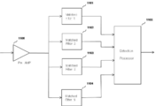
The block diagram of the
If any one node wants to transmit data, it first checks the received signal to see if another node is transmitting data. If no node is transmitting data, data is transmitted. If there is data to be sent such as location information, code information, detection information, and no other SONAR is in data transmission, the
The block diagram of the location information acquisition apparatus is the same as the ultrasonic communicator except for the dotted line portion, and is the same as the entire block diagram including the dotted line portion in FIG. 12. As shown in FIG. 12, the position information acquisition apparatus includes an
The communication between the location information acquisition device and the location information acquisition device and the location information transmission device uses a CSMA / CD communication method to efficiently use limited ultrasonic frequency resources. Therefore, if any one device wants to transmit data, it first checks the received signal to see if another device is transmitting data. If no device is transmitting data, it transmits data.
If there is data to be sent by the location information transmission device such as DGPS information and transmission time information, and no other device is transmitting data, the
The ultrasonic signal reaching the position information acquisition device is received by the
The
In addition, the
Fig. 13 is a block diagram of a PIA identification SONAR and a virtual pulse transmitting device. The PIA identification SONAR and the virtual pulse transmitter are the same on the block diagram, except that the virtual pulse transmitter has an additional keyboard and display for inputting a time delay encryption code.
PIA identification SONAR is FPGA (1301), D / A CONVERTER (1302), LOW PASS FILTER (1303, 1308), POWER AMP (1304), DUPLEXER (1305), ultrasonic vibrator (1306), LOW NOISE AMP as shown in FIG. 1307, A /
The
The output signal of the D /
If it is determined that the object generating the reflected wave is a trap or a submarine, the
14 is a configuration diagram of each ultrasonic remote blasting apparatus. Ultrasonic remote blasting apparatus is
16 is a diagram illustrating a
17 shows a node being installed through a remote control device. The
When the
If the bottom of the floor is mud, sand, or surface, replace the jig for mounting fixture (2009) instead of the robot hand (1703), and in the front portion (1801) shown in Fig. Hold it firmly by applying magnetic force and place it at the point to be fixed and rotate it while pressing. At this time, the rotational force is transmitted by the
In order to make the
When the
If the sea floor is rocky terrain, the
In order to fix the
When the
Communication between the
22 is a view showing a node fixed by using the fixing device when the sea floor is mud, mud, the day after tomorrow. When the distance to the rigid point is large, that is, when the expansion part of the fixing device takes a lot, it is fixed by three or
The
In this way, it is possible to detect and respond to submarine submarines early, quickly and accurately, even in difficult situations, such as the West Sea, where the water depth is low, the water temperature difference is large, the tide changes are large, and the operation of general fishing boats is active. It was.
101: node 102: RF relay hub
103: trap monitor 104: control center monitor
201, 202, 203, 204, 205, 206, 207, 208, 209: nodes
210: RF relay hub
301: FREQUENCY & TIME set
302: SONAR pulse
401: SONAR transmission pulse 402: reflected wave
403: response pulse 404:
405:
407 SONAR pulse 4
510, 520, 530, 540, 550, 560, 570: SONAR cells
511, 512, 513, 514, 515, 516, 517, 518, 519: nodes
601, 602, 603, 604, 605, 606, 607, 608: nodes
Nodes: 609, 610, 611, 612, 613, 614, 615, 616
701: location information acquisition device 702: location information transmission device
801: location information acquisition device to be installed
802, 803, 804: existing location information acquisition device
901: SONAR 902: CPU
903:
906: generator 907: power supply
908: Posture sensor 909: DRIVER
910: base 914: router
1001: FPGA 1002: D / A CONVERTER
1003: LOW PASS FILTER 1004: POWER AMP
1005: DUPLEXER 1006: oscillator
1007: reception signal processing unit 1008: CPU
1101, 1102, 1103, 1104: MATCHED FILTER
1105: DETECTION PROCESSOR 1106: PRE AMP
1201: FPGA 1202: D / A CONVERTER
1203, 1208: LOW PASS FILTER 1204: POWER AMP
1205: DUPLEXER 1206: oscillator
1207: LOW NOISE AMP 1209: A / D CONVERTER
1210: CPU
1301: FPGA 1302: D / A CONVERTER
1303, 1308: LOW PASS FILTER 1304: POWER AMP
1305: DUPLEXER 1306: oscillator
1307: LOW NOISE AMP 1309: A / D CONVERTER
1310: input and output unit
1401
1403: drive device 1404: control device
1405: communication device 1406: ultrasonic vibrator
1407: detection sensor 1408: power supply
1501:
1503:
1505, 1510, 1511: Rudder
1601: protection net 1602: base
1603, 1604, 1605, 1606, 1607, 1608, 1609: vibrator
1701: unmanned submersible body 1702: support legs
1703: robot hand 1704: CCTV camera
1705: lid 1706: screw
1707: Guard Net 1708: Monitor
1709: fixing device 1710: device to install
1801: front portion 1802: lid
1803: headlight 1804: CCTV camera
1805: Body 1806: Robot hand support
1807: support leg support 1808: support leg
1809: robot hand 1810: fixture jig
1811: fixing device 1812: device to install
1901: robot wrist 1902: joint 1
1903
1905:
1907:
1909: outermost part of the support bridge 1910: second outer part
1911: third outer portion 1912: internal axis
1913, 1914, 1915, 1916: home
2001: Fixture for shock absorber 2002: Female thread
2003: Top 2004: Expansion Unit
2005: Male 2006: Female
2007: Top side 2008: Bottom side
2009, 2013, 2021:
2011, 2015, 2019:
2020: jaw
2101: rock fixing device 2102: head
2103, 2106:
2105, 2108: Female thread
2109, 2112, 2115, 2118: Fixture jig
2110, 2113, 2116, 2117: inside of fixture
2111, 2114, 2119: support shaft
2201, 2202, 2203: Fixing
2205: Protection net 2206, 2207, 2208: Bolt
Claims (2)
A SONAR that provides a unique code for each node and networked the neighboring nodes to receive reflection waves from each other, thereby improving shading problems, and enabling pia identification in a simple manner using the characteristics of the SONAR;
A CPU that manages the control, storage, calculation, processing, determination, and data communication of the sonar, the router, the ultrasonic communicator, the attitude sensor, the driver, the generator, and the power supply which constitute the node;
An ultrasonic communicator for transmitting / receiving data between neighboring nodes, a ship and control center, an installation bus and a remote control device;
A router providing an optimal transfer path for transmitting data to a desired destination through relay transmission of a neighbor node;
An ultrasonic vibrator for freely directing ultrasonic pulses in up, down, left and right directions by using a protective net structure;
A generator for generating electricity efficiently and stably in accordance with the protection network structure by using algae under the sea;
A power supply for supplying power to each node of the node and storing surplus power in a storage battery;
A posture detector for detecting postures and moving positions of the nodes and sending them to a control center for quick calibration and update of positions;
A driver for correcting the posture of the base by the posture detector and the CPU by itself;
A base for fixing each part of the node and allowing height and inclination adjustment;
A protection net for realizing the structure of the mosquito net and protecting each part of the generator, the sensor, the control device, the detonator, the posture control and the communication device;
A locking fixture for length extension along the depth of the rock and a rock anchor for installation in a rock area;
Remote installation equipment that enables the installation of nodes remotely from the mothership;
Inland submarine boundary method and system.
An electric primer for installing a nichrome wire in the gunpowder to detonate the mine by applying power;
A driving device for amplifying electric power at an intensity capable of receiving a control signal and operating an electric primer;
A control device that decodes the signal received from the communication device, sends a detonation signal to the drive device, and sends the submarine detection signal received from the detection sensor into a digital signal and sends the signal to the communication device;
A communication device for receiving an ultrasonic signal from an ultrasonic vibrator, extracting a digital signal and sending the digital signal to a control device, and converting the digital data received from the control device into an ultrasonic wave and sending the digital data to an ultrasonic vibrator;
An ultrasonic vibrator;
A detection sensor;
A power supply unit for converting and supplying power generated by the self-generator to an appropriate voltage for each unit and for charging extra electricity;
Connecting a remote blasting device to a node of the submarine boundary device to add a blow function to the submarine boundary device;
Or implementing a separate node consisting of the respective parts to implement an independent ultrasonic remote blasting network and apparatus.
Priority Applications (1)
| Application Number | Priority Date | Filing Date | Title |
|---|---|---|---|
| KR1020100069744A KR20120009640A (en) | 2010-07-19 | 2010-07-19 | Antisubmarine warning system for the shallow sea |
Applications Claiming Priority (1)
| Application Number | Priority Date | Filing Date | Title |
|---|---|---|---|
| KR1020100069744A KR20120009640A (en) | 2010-07-19 | 2010-07-19 | Antisubmarine warning system for the shallow sea |
Publications (1)
| Publication Number | Publication Date |
|---|---|
| KR20120009640A true KR20120009640A (en) | 2012-02-02 |
Family
ID=45834410
Family Applications (1)
| Application Number | Title | Priority Date | Filing Date |
|---|---|---|---|
| KR1020100069744A KR20120009640A (en) | 2010-07-19 | 2010-07-19 | Antisubmarine warning system for the shallow sea |
Country Status (1)
| Country | Link |
|---|---|
| KR (1) | KR20120009640A (en) |
Cited By (4)
| Publication number | Priority date | Publication date | Assignee | Title |
|---|---|---|---|---|
| WO2014068231A3 (en) * | 2012-10-30 | 2014-07-17 | Seb S.A. | Electric household appliance for culinary preparation, comprising a pressing screw and at least one filter |
| JP2015205677A (en) * | 2013-10-15 | 2015-11-19 | オコム・テクノロジー・リミテッド・ライアビリティ・カンパニーOcom Technology Llc | Submarine optical fiber network |
| US9277471B2 (en) | 2012-11-01 | 2016-03-01 | Intel Corporation | Channel state information feedback scheme for cooperative multi point transmission and carrier aggregation scenario |
| KR101961380B1 (en) | 2018-07-20 | 2019-03-22 | 박영철 | System and method for non-acoustic underwater submarine and object detection, and a recording medium having computer readable program for executing the method |
-
2010
- 2010-07-19 KR KR1020100069744A patent/KR20120009640A/en not_active Application Discontinuation
Cited By (5)
| Publication number | Priority date | Publication date | Assignee | Title |
|---|---|---|---|---|
| WO2014068231A3 (en) * | 2012-10-30 | 2014-07-17 | Seb S.A. | Electric household appliance for culinary preparation, comprising a pressing screw and at least one filter |
| EP3202289A1 (en) * | 2012-10-30 | 2017-08-09 | Seb S.A. | Kitchen appliance comprising a pressing screw and at least one filter |
| US9277471B2 (en) | 2012-11-01 | 2016-03-01 | Intel Corporation | Channel state information feedback scheme for cooperative multi point transmission and carrier aggregation scenario |
| JP2015205677A (en) * | 2013-10-15 | 2015-11-19 | オコム・テクノロジー・リミテッド・ライアビリティ・カンパニーOcom Technology Llc | Submarine optical fiber network |
| KR101961380B1 (en) | 2018-07-20 | 2019-03-22 | 박영철 | System and method for non-acoustic underwater submarine and object detection, and a recording medium having computer readable program for executing the method |
Similar Documents
| Publication | Publication Date | Title |
|---|---|---|
| KR101157169B1 (en) | Deployable undersea surveillance system | |
| US6813218B1 (en) | Buoyant device for bi-directional acousto-optic signal transfer across the air-water interface | |
| US9845137B2 (en) | Methods and underwater bases for using autonomous underwater vehicle for marine seismic surveys | |
| US20170015395A1 (en) | Methods and underwater bases for using autonomous underwater vehicle for marine seismic surveys | |
| US20160359570A1 (en) | Measurement system for seas, rivers and other large water bodies | |
| EP1381878B1 (en) | Positioning system | |
| US10502828B2 (en) | System for detecting subsurface objects and unmanned surface vessel | |
| KR20120009640A (en) | Antisubmarine warning system for the shallow sea | |
| KR101223184B1 (en) | Geometical survey system based on gps | |
| US20170142323A1 (en) | Camera system and control method therefor, and electronic device and control program therefor | |
| US7813223B1 (en) | System and method for focusing a kinetic pulse array | |
| CN108423140A (en) | Omnidirectional's Active Acoustic barrier system | |
| JP2022031576A (en) | Anti-torpedo defense system | |
| CN109781382A (en) | It is a kind of to there is cable subsurface buoy internal wave of ocean to monitor system based on vector sensor | |
| US20090262600A1 (en) | Methods and apparatus for surveillance sonar systems | |
| EP2005212B1 (en) | Swimmer detection sonar network | |
| Wawrzyniak et al. | Detecting small moving underwater objects using scanning sonar in waterside surveillance and complex security solutions | |
| KR102049302B1 (en) | Underwater metal detector and submarine detection apparatus including the detector | |
| KR20120006686A (en) | Sonar network for the shallow sea | |
| KR20120004889A (en) | Distributed sonar | |
| CN107121668A (en) | The detection system of space exploration node | |
| RU2548937C1 (en) | System of objects guarding from water side with information direct transmission via border water-air | |
| US10152562B1 (en) | Submerged surveillance node | |
| CN113050097A (en) | Seabed vacuum pipeline sonar system and working method | |
| CN110823294A (en) | Floating type underwater information intelligent monitoring system |
Legal Events
| Date | Code | Title | Description |
|---|---|---|---|
| A201 | Request for examination | ||
| E601 | Decision to refuse application | ||
| E601 | Decision to refuse application |