KR20120007263U - electronic-cigarette with cartridge - Google Patents
electronic-cigarette with cartridge Download PDFInfo
- Publication number
- KR20120007263U KR20120007263U KR2020110003117U KR20110003117U KR20120007263U KR 20120007263 U KR20120007263 U KR 20120007263U KR 2020110003117 U KR2020110003117 U KR 2020110003117U KR 20110003117 U KR20110003117 U KR 20110003117U KR 20120007263 U KR20120007263 U KR 20120007263U
- Authority
- KR
- South Korea
- Prior art keywords
- cartridge
- liquid
- hole
- wick
- housing
- Prior art date
Links
Images


Classifications
-
- A—HUMAN NECESSITIES
- A24—TOBACCO; CIGARS; CIGARETTES; SIMULATED SMOKING DEVICES; SMOKERS' REQUISITES
- A24F—SMOKERS' REQUISITES; MATCH BOXES; SIMULATED SMOKING DEVICES
- A24F40/00—Electrically operated smoking devices; Component parts thereof; Manufacture thereof; Maintenance or testing thereof; Charging means specially adapted therefor
- A24F40/40—Constructional details, e.g. connection of cartridges and battery parts
- A24F40/42—Cartridges or containers for inhalable precursors
-
- A—HUMAN NECESSITIES
- A24—TOBACCO; CIGARS; CIGARETTES; SIMULATED SMOKING DEVICES; SMOKERS' REQUISITES
- A24B—MANUFACTURE OR PREPARATION OF TOBACCO FOR SMOKING OR CHEWING; TOBACCO; SNUFF
- A24B15/00—Chemical features or treatment of tobacco; Tobacco substitutes, e.g. in liquid form
- A24B15/10—Chemical features of tobacco products or tobacco substitutes
- A24B15/16—Chemical features of tobacco products or tobacco substitutes of tobacco substitutes
- A24B15/167—Chemical features of tobacco products or tobacco substitutes of tobacco substitutes in liquid or vaporisable form, e.g. liquid compositions for electronic cigarettes
-
- A—HUMAN NECESSITIES
- A24—TOBACCO; CIGARS; CIGARETTES; SIMULATED SMOKING DEVICES; SMOKERS' REQUISITES
- A24F—SMOKERS' REQUISITES; MATCH BOXES; SIMULATED SMOKING DEVICES
- A24F40/00—Electrically operated smoking devices; Component parts thereof; Manufacture thereof; Maintenance or testing thereof; Charging means specially adapted therefor
- A24F40/10—Devices using liquid inhalable precursors
-
- A—HUMAN NECESSITIES
- A24—TOBACCO; CIGARS; CIGARETTES; SIMULATED SMOKING DEVICES; SMOKERS' REQUISITES
- A24F—SMOKERS' REQUISITES; MATCH BOXES; SIMULATED SMOKING DEVICES
- A24F40/00—Electrically operated smoking devices; Component parts thereof; Manufacture thereof; Maintenance or testing thereof; Charging means specially adapted therefor
- A24F40/40—Constructional details, e.g. connection of cartridges and battery parts
- A24F40/44—Wicks
-
- A—HUMAN NECESSITIES
- A24—TOBACCO; CIGARS; CIGARETTES; SIMULATED SMOKING DEVICES; SMOKERS' REQUISITES
- A24F—SMOKERS' REQUISITES; MATCH BOXES; SIMULATED SMOKING DEVICES
- A24F40/00—Electrically operated smoking devices; Component parts thereof; Manufacture thereof; Maintenance or testing thereof; Charging means specially adapted therefor
- A24F40/40—Constructional details, e.g. connection of cartridges and battery parts
- A24F40/48—Fluid transfer means, e.g. pumps
- A24F40/485—Valves; Apertures
-
- A—HUMAN NECESSITIES
- A61—MEDICAL OR VETERINARY SCIENCE; HYGIENE
- A61M—DEVICES FOR INTRODUCING MEDIA INTO, OR ONTO, THE BODY; DEVICES FOR TRANSDUCING BODY MEDIA OR FOR TAKING MEDIA FROM THE BODY; DEVICES FOR PRODUCING OR ENDING SLEEP OR STUPOR
- A61M15/00—Inhalators
- A61M15/06—Inhaling appliances shaped like cigars, cigarettes or pipes
Landscapes
- Health & Medical Sciences (AREA)
- Engineering & Computer Science (AREA)
- Biomedical Technology (AREA)
- Heart & Thoracic Surgery (AREA)
- Chemical Kinetics & Catalysis (AREA)
- Bioinformatics & Cheminformatics (AREA)
- Pulmonology (AREA)
- Anesthesiology (AREA)
- Chemical & Material Sciences (AREA)
- General Chemical & Material Sciences (AREA)
- Hematology (AREA)
- Life Sciences & Earth Sciences (AREA)
- Animal Behavior & Ethology (AREA)
- General Health & Medical Sciences (AREA)
- Public Health (AREA)
- Veterinary Medicine (AREA)
- Disinfection, Sterilisation Or Deodorisation Of Air (AREA)
Abstract
본 고안은 카트리지 일체형 전자담배에 관한 것으로, 더욱 상세하게는 카트리지를 본체와 일체로 결합하여 카트리지를 본체에서 분리하지 않고 액상을 재충전하여 사용할 수 있도록 하고, 사용 중 카트리지에 저장된 액상이 외부로 누수되는 것을 방지한 카트리지 일체형 전자담배에 관한 것이다.
이를 위해 본 고안은, 상하로 관통되고 내측으로 수납공간이 형성되는 상부커버와, 상기 상부커버와 착탈 가능하게 결합되며 내부에 배터리가 구비된 하부몸체로 이루어진 본체와;, 상기 상부커버에 착탈 가능하게 결합되고 사용자가 입에 물고 증기를 흡입하는 물부리와;, 상기 상부커버에 일체로 고정되고 내측에 액상을 저장하기 위한 수용공간이 형성되되, 상단에는 액상의 재충전을 위한 충전공이 형성되고 상기 충전공을 통해 액상을 충전할 때 수용공간 내부의 공기를 외부로 배출하는 공기출입공이 형성되고 하단 중앙에는 관통공이 형성된 카트리지와;, 상기 카트리지의 수용공간에 저장된 액상을 공급받아 가열함으로써 증기를 발생시키되, 하부는 밀폐되고 상부는 개구된 하우징과, 상기 하우징의 상부 개구를 덮되 발생된 증기가 상방으로 이동될 수 있도록 개구부가 형성되며 상부 중앙에는 상기 카트리지의 하부 관통공에 삽입 결합되어 카트리지 내부에 저장된 액상을 유입시키기 위한 돌출관이 형성된 커버와, 상기 하우징 내부에 배치되고 상단이 상기 돌출관에 삽입되어 돌출관으로 유입되는 액상을 흡수하는 심지와, 상기 하우징내에 구비되고 상기 심지와 접촉되어 심지에 흡수된 액상을 가열하는 가열수단을 포함하는 무화기를 포함하여 이루어진다.The present invention relates to a cartridge-integrated electronic cigarette, and more specifically, by combining the cartridge integrally with the main body so that the liquid can be recharged without separating the cartridge from the main body, the liquid stored in the cartridge is leaked to the outside during use The present invention relates to a cartridge integrated electronic cigarette which is prevented from being prevented.
To this end, the present invention, the upper cover penetrates up and down and the storage space is formed inward, and the main body made of a lower body having a battery therein and detachably coupled to the upper cover; A water beak coupled to the user and sucking the steam by the user, and a receiving space is integrally fixed to the upper cover and formed to store a liquid inside, and a filling hole for refilling the liquid is formed at the top of the filling When the liquid filling through the ball is formed in the air inlet hole for discharging the air inside the receiving space to the outside and the through hole is formed in the bottom center; and, by receiving the liquid stored in the receiving space of the cartridge to generate steam by heating The lower part is sealed and the upper part is opened, and the upper opening of the housing is covered with the generated steam upwards. An opening is formed so as to be movable, and a cover is formed in the upper center, which is inserted into and coupled to the lower through hole of the cartridge to form a projection tube for introducing a liquid stored in the cartridge, and is disposed inside the housing and has an upper end inserted into the projection tube. And an atomizer including a wick absorbing the liquid phase flowing into the protruding tube and heating means provided in the housing and in contact with the wick to heat the liquid absorbed in the wick.
Description
본 고안은 카트리지 일체형 전자담배에 관한 것으로, 더욱 상세하게는 카트리지를 본체와 일체로 결합하여 카트리지를 본체에서 분리하지 않고 액상을 재충전하여 사용할 수 있도록 하고, 사용 중 카트리지에 저장된 액상이 외부로 누수되는 것을 방지한 카트리지 일체형 전자담배에 관한 것이다.
The present invention relates to a cartridge-integrated electronic cigarette, and more specifically, by combining the cartridge integrally with the main body so that the liquid can be recharged without separating the cartridge from the main body, the liquid stored in the cartridge is leaked to the outside during use The present invention relates to a cartridge integrated electronic cigarette which is prevented from being prevented.
담배는, 기호 식품의 일종으로 많은 사람이 애용하고 있으나, 흡입할 때 발생하는 니코틴, 타르 등이 흡연자의 몸에 직접적인 피해를 주게 되며, 연초담배가 탈 때 발생하는 연기에 포함된 성분이 주변 사람들에게는 간접 흡연의 피해를 주고 있다. 이로 인해 근래에 들어서는 흡연할 수 있는 장소가 점점 줄어들고 있으며, 흡연자 스스로도 백해무익한 연초담배를 줄이거나 끊기 위한 계획을 세우게 된다.Cigarettes are a favorite food that many people use, but nicotine and tar generated when inhaling them directly damage the smoker's body. It does damage of secondhand smoking. As a result, in recent years, there are fewer and fewer places to smoke, and smokers themselves are planning to reduce or stop the useless tobacco smoke.
그러나, 흡연자들은 오랜 습관과 중독성 때문에 쉽게 연초담배를 끊기가 어렵다.
However, it is difficult for smokers to quit smoking easily because of old habits and addictions.
근래에 들어서 개발된 전자담배는, 연초담배와 비슷한 외형을 가지고 사용하는 방법이 유사하고, 액상을 가열하여 발생하는 증기가 흡연자에게 실제 담배를 피우는 듯한 느낌을 갖게 하고, 상기 증기에 포함된 유해한 성분이 연초담배에 비해 줄어 간접 흡연으로 인한 피해를 줄이고, 연초담배 특유의 냄새 대신에 액상에 첨가된 박하, 복숭아 등으로 인하여 사용자 및 주변 사람에게 불쾌감을 전달하지 않는다.
In recent years, the developed electronic cigarette has a similar appearance to that of tobacco tobacco, and the vapor generated by heating the liquid makes the smoker feel as if he is actually smoking a cigarette, and the harmful components contained in the vapor. Compared to this tobacco cigarette, it reduces the damage caused by second-hand smoke, and does not convey discomfort to users and people around due to peppermint, peaches, etc. added to the liquid instead of the tobacco-specific smell.
현재 판매되고 있는 대부분의 전자담배는, 저장된 소량의 액상을 다 사용한 후 재충전하여 사용하는 방법과 다량의 액상이 저장된 카트리지를 본체에 결합하여 사용한 후 교체하는 방법이 있다.
Most of the currently sold electronic cigarettes, there is a method of refilling after using a small amount of the stored liquid and a method of replacing the cartridge after storing a large amount of liquid stored in the body used.
그러나, 소량의 액상을 충전하여 사용하는 방법은, 저장된 액상의 양에 따라 사용할 수 있는 횟수가 제한되기 때문에 자주 충전해야 하고, 외부로 이동시 액상통을 별도로 휴대해야 하는 불편함이 있고,However, the method of filling and using a small amount of liquid is limited because the number of times that can be used depending on the amount of liquid stored is often required to be filled, and the inconvenience of having to carry the liquid container separately when moving to the outside,
다량의 액상을 충전한 일회용 카트리지를 사용하는 방법은, 저장된 액상의 양이 대량이기 때문에 장시간 사용하기 편리한 장점이 있으나, 카트리지에 저장된 액상을 사용한 후 카트리지를 버리는 형태이기 때문에 쓰레기가 발생하게 되고, 카트리지의 개당 가격이 비싸지는 문제점이 있었다.
The method of using a disposable cartridge filled with a large amount of liquid has an advantage of being convenient for a long time because the amount of the stored liquid is large, but since the cartridge is discarded after using the liquid stored in the cartridge, garbage is generated. There was a problem that the price per piece was expensive.
또한, 상기의 방법 모두에서 카트리지 내부와 외부의 압력차이가 있기 때문에 카트리지에 충전된 액상이 무화기가 위치한 하부로 원활하게 이동하지 않는 문제점이 있었다.
In addition, in all of the above methods, there is a problem in that the liquid phase filled in the cartridge does not move smoothly to the lower part of the atomizer because there is a pressure difference between the inside and the outside of the cartridge.
본 고안은 상기와 같은 문제점을 해결하기 위해 제안된 것으로, 본체에 대량의 액상을 저장할 수 있는 카트리지를 일체로 구비하여 장시간 사용이 가능하고, 액상의 재충전이 가능하여 폐기되는 카트리지가 없어 쓰레기가 생기지 않는 카트리지 일체형 전자담배를 제공하는데 목적이 있다.
The present invention has been proposed to solve the above problems, it is possible to use a long time by integrally equipped with a cartridge that can store a large amount of liquid in the body, the liquid can be refilled because there is no cartridge to be discarded waste is not generated The purpose is to provide a cartridge-integrated electronic cigarette.
또한, 액상을 재충전할 때 카트리지 내부의 공기를 외부로 배출하여 재충전을 용이하게 하고, 사용 중 외부 공기를 카트리지 내부로 유입시켜 액상이 원활하게 이동되도록 하는 카트리지 일체형 전자담배를 제공하는데 목적이 있다.
In addition, it is an object to provide a cartridge-integrated electronic cigarette to discharge the air inside the cartridge to the outside when refilling the liquid phase to facilitate refilling, and to introduce the outside air into the cartridge during use to smoothly move the liquid phase.
상기와 같은 목적을 달성하기 위하여 본 고안은, 상하로 관통되고 내측으로 수납공간이 형성되는 상부커버와, 상기 상부커버와 착탈 가능하게 결합되며 내부에 배터리가 구비된 하부몸체로 이루어진 본체와;, 상기 상부커버에 착탈 가능하게 결합되고 사용자가 입에 물고 증기를 흡입하는 물부리와;, 상기 상부커버에 일체로 고정되고 내측에 액상을 저장하기 위한 수용공간이 형성되되, 상단에는 액상의 재충전을 위한 충전공이 형성되고 상기 충전공을 통해 액상을 충전할 때 수용공간 내부의 공기를 외부로 배출하는 공기출입공이 형성되고 하단 중앙에는 관통공이 형성된 카트리지와;, 상기 카트리지의 수용공간에 저장된 액상을 공급받아 가열함으로써 증기를 발생시키되, 하부는 밀폐되고 상부는 개구된 하우징과, 상기 하우징의 상부 개구를 덮되 발생된 증기가 상방으로 이동될 수 있도록 개구부가 형성되며 상부 중앙에는 상기 카트리지의 하부 관통공에 삽입 결합되어 카트리지 내부에 저장된 액상을 유입시키기 위한 돌출관이 형성된 커버와, 상기 하우징 내부에 배치되고 상단이 상기 돌출관에 삽입되어 돌출관으로 유입되는 액상을 흡수하는 심지와, 상기 하우징내에 구비되고 상기 심지와 접촉되어 심지에 흡수된 액상을 가열하는 가열수단을 포함하는 무화기를 포함하여 이루어진다.
In order to achieve the above object, the present invention, the upper cover penetrates up and down and the receiving space is formed inwardly, the main body consisting of a lower body having a battery therein and detachably coupled to the upper cover; A water bead detachably coupled to the upper cover and a user bites into the mouth and sucks steam; A receiving space is formed integrally with the upper cover and stores a liquid inside, and at the top for refilling the liquid. A filling hole is formed and an air access hole for discharging air in the receiving space to the outside when the liquid is filled through the filling hole is formed, and a through hole is formed at the bottom center thereof; Heating generates a vapor, the lower part of which is closed and the upper part of the housing, which covers the upper opening of the housing. An opening is formed to allow the generated steam to move upwards, and a cover having a protruding tube inserted into and coupled to a lower through hole of the cartridge to introduce a liquid stored inside the cartridge, and disposed inside the housing and having an upper end at an upper center thereof. And an atomizer including a wick inserted into the protruding tube and absorbing the liquid phase flowing into the protruding tube, and heating means provided in the housing and in contact with the wick to heat the liquid absorbed in the wick.
또한, 상기 카트리지에는, 상기 충전공과 공기출입공이 형성된 마개가 더 구비되되, 상기 마개는 하부에 끼움홈이 형성되고, 상기 카트리지에는 상부로 돌출된 끼움돌기가 형성되어 상기 마개가 카트리지에 착탈 가능하게 결합되는 것을 특징으로 한다.
The cartridge may further include a stopper having the filling hole and the air access hole formed therein, and the stopper may have a fitting groove formed at a lower portion thereof, and the cartridge may have a fitting protrusion projecting upwardly to allow the stopper to be detachable from the cartridge. It is characterized by being combined.
또한, 상기 물부리의 결합공에는 카트리지의 충전공을 폐쇄하는 막음봉이 더 구비된 것을 특징으로 한다.
In addition, the coupling hole of the water bill is characterized in that the blocking rod for closing the filling hole of the cartridge is further provided.
이때, 상기 막음봉은, 상단은 상기 흡입공의 일측에 일체로 고정되고, 하단은 상기 결합공의 하부로 노출된 원형의 봉으로 이루어지되, 상기 상단은 증기의 이동을 방해하지 않도록 상기 흡입공의 직경보다 작은 크기로 납작하게 형성된 것을 특징으로 한다.
At this time, the blocking rod, the upper end is integrally fixed to one side of the suction hole, the lower end is made of a circular rod exposed to the lower portion of the coupling hole, the upper end of the suction hole so as not to interfere with the movement of steam It is characterized in that it is formed flat in size smaller than the diameter.
또한, 상기 돌출관에는, 액상이 원활하게 유입되도록 외주면에 길이방향을 따라 절개홈이 더 형성된 것을 특징으로 한다.
In addition, the protrusion tube, characterized in that the incision groove is further formed along the longitudinal direction on the outer peripheral surface so that the liquid flows smoothly.
나아가, 상기 하우징에는, 내측 저면에 심지를 통해 유입된 액상이 외부로 누수되는 것을 방지하기 위한 차단구가 구비되는 것을 특징으로 한다.
In addition, the housing, characterized in that provided with a block for preventing the liquid flowed through the wick in the inner bottom surface to the outside leak.
이때, 상기 차단구는 실리콘으로 구성되어 하우징의 저면을 밀봉하고, 중앙 상부에는 중앙돌기가 형성되며, 상기 중앙돌기 외주면에는 심지의 하단부가 권취된 것을 특징으로 한다.
At this time, the block is made of silicon to seal the bottom surface of the housing, the central projection is formed in the upper center, characterized in that the lower end of the wick is wound on the outer peripheral surface of the central projection.
상기와 같이 이루어진 본 고안은, 다량의 액상이 저장된 카트리지를 구비하여 장시간 사용이 가능하고, 카트리지를 본체에 일체로 구비하여 재활용할 수 있어 환경 오염을 줄이는 장점이 있으며,The present invention made as described above is provided with a cartridge in which a large amount of liquid is stored, and thus can be used for a long time.
상기 카트리지의 상부에는 외부 공기를 카트리지 내부로 유입시키기 위한 공기유입공이 형성되어 카트리지에 저장된 액상을 가압하여 하부로 원활하게 이동시켜 사용 중 심지가 건조해져 가열수단에 의해 타는 것을 방지하고,An air inlet hole is formed in the upper portion of the cartridge to introduce external air into the cartridge to pressurize the liquid stored in the cartridge to move smoothly to the lower portion, thereby preventing the wick from drying and burning by the heating means.
상기 심지가 삽입되는 돌출관에 액상의 유입을 빠르게 진행시키기 위한 절개홈을 더 형성하여 사용의 편의성을 향상시킨 장점이 있다
There is an advantage of improving the convenience of use by further forming a cutting groove for rapidly advancing the liquid into the protruding tube into which the wick is inserted
도 1 은 본 고안에 따른 카트리지 일체형 전자담배를 도시한 사시도.
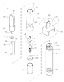
도 2a 는 본 고안에 따른 카트리지 일체형 전자담배를 분해한 상태의 분해사시도.
도 2b 는 본 고안의 다른 실시예에 따른 카트리지를 도시한 분해사시도.
도 3 은 본 고안에 따른 카트리지 일체형 전자담배의 결합 상태를 도시한 단면도.
도 4 는 본 고안에 따른 카트리지 일체형 전자담배에서 액상이 이동 상태 및 재충전 상태를 도시한 상태도.
도 5 는 본 고안에 따른 카트리지 일체형 전자담배에서 증기가 이동하는 상태를 도시한 상태도.
도 6 은 본 고안에 따른 카트리지 일체형 전자담배에서 무화기의 성형 실시예를 도시한 개략도.
도 7 은 본 고안에 따른 카트리지에 액상을 재충전하는 상태를 도시한 상태도.1 is a perspective view showing a cartridge integrated electronic cigarette according to the present invention.
Figure 2a is an exploded perspective view of a state in which the cartridge integrated electronic cigarette according to the present invention.
Figure 2b is an exploded perspective view showing a cartridge according to another embodiment of the present invention.
Figure 3 is a cross-sectional view showing a combined state of the cartridge integrated electronic cigarette according to the present invention.
Figure 4 is a state diagram showing a liquid state moving state and a refilled state in the cartridge integrated electronic cigarette according to the present invention.
Figure 5 is a state diagram showing a state in which steam moves in the cartridge integrated electronic cigarette according to the present invention.
Figure 6 is a schematic view showing a molding embodiment of the atomizer in the cartridge integrated electronic cigarette according to the present invention.
Figure 7 is a state diagram showing a state of refilling the liquid in the cartridge according to the present invention.
이하, 첨부된 도면을 참조하여 본 고안에 따른 카트리지 일체형 전자담배의 바람직한 구현예를 설명하도록 한다.
Hereinafter, with reference to the accompanying drawings to describe a preferred embodiment of the cartridge integrated electronic cigarette according to the present invention.
본 고안에 따른 카트리지 일체형 전자담배(1)는, 본체(10), 물부리(20), 카트리지(30), 무화기(40)를 포함하여 이루어진다.
Cartridge integrated
상기 본체(10)는, 내측으로 수납공간(111)이 형성되어 후술하는 카트리지(30)와 무화기(40)가 삽입 고정되는 상부커버(11)와, 상기 상부커버(11)와 착탈 가능하게 결합되며, 상기 무화기(40)에 전원을 공급하는 배터리(121)가 내부에 구비되고 상기 배터리(121)의 잔량을 외부로 표시하는 표시부(124)와 사용 중 외부로 빛을 조사하여 사용상태를 표시하는 발광부(125)가 구비된 하부몸체(12)로 이루어진다.
The main body 10 has a
상기 상부커버(11)는, 내부가 상하 방향으로 관통된 원통형으로 이루어지되, 상부에서 하부를 향해 점진적으로 직경이 넓어지도록 형성되고, 하부 말단에 하부몸체(12)와 결합되기 위한 나사산(112)이 형성되고, 외부에서 내부를 확인할 수 있도록 투시창(115)이 더 구비된다.
The
또한, 상부커버(11)의 내주면에는 길이 방향을 따라 후술하는 무화기(40)에 의해 변환된 증기(S)가 이동하는 증기통로(114)가 구비되되, 상기 증기통로(114)는 후술하는 카트리지(30)가 결합된 후 카트리지(30)와 상부커버(11)의 내주면 사이에 형성되는 공간이다.
In addition, the inner circumferential surface of the
상기 하부몸체(12)는, 상기 상부커버(11)와 착탈 가능하게 결합되어 본체(10)를 형성하는 것으로, 상기 상부커버(11)와 착탈 가능하게 결합되기 위한 대응나사산(122)이 형성되고, 상기 배터리(121)를 후술하는 무화기(40)와 연통시키기 위한 스위치(123)가 더 구비된다.
The
상기 표시부(124)는, 배터리(121)의 잔량을 외부에서 쉽게 확인할 수 있도록 하기 위한 것으로, 다수개의 LED(124a)를 배열한 후 배터리(121)의 잔량에 따라 순차적으로 소등되도록 한 것이다.The
본 고안에서는 상기 표시부(124)의 일 실시예로서, 다수개의 LED(124a)와 더불어 제품을 표현하는 문자(124b)를 구비한 후 상기 문자(124b)를 분할하여 LED(124a)와 더불어 소등되도록 한 것을 도시하였다.
In the present invention, as an embodiment of the
상기 발광부(125)는, 상기 스위치(123)와 연동하여 작동 상태를 외부에 표시하는 것이며, 상기 하부몸체(12)의 하단에 구비되되, 상기 표시부(124)와 연동되어 배터리(121)의 잔량에 따라 상이한 색상을 조사할 수 있도록 할 수 있고, 상기 배터리(121)를 재충전할 때 일정 시간마다 빛이 점등되도록 하여 재충전상태를 표시할 수 있도록 할 수 있다.
The
상기 물부리(20)는, 상기 상부커버(11)와 착탈 가능하게 결합하고, 사용자가 입에 물고 증기(S)를 흡입하는 것으로, 상부는 사용자가 입에 물기 편안하도록 납작하게 형성되며 상단에는 사용자가 흡입하는 증기가 이동하는 흡입공(21)이 형성되고, 하부는 상기 상부커버(11)와 결합하기 위한 하단 결합공(22)이 형성되며, 상기 결합공(22)에는 후술하는 카트리지(30)의 충전공(32)을 폐쇄하는 막음봉(23)이 더 구비된다.
The
상기 막음봉(23)은, 상단은 상기 흡입공(21)의 일측에 일체로 고정되고, 하단은 상기 결합공(22)의 하부로 노출된 원형의 봉으로, 노출된 하단 봉이 후술하는 카트리지(30)에 형성된 충전공(32)에 삽입되면서 폐쇄하고, 상단은 상기 흡입공(21)을 통해 이동하는 증기(S)의 이동을 방해하지 않도록 흡입공(21)의 직경보다 작은 크기로 납작하게 형성되어 흡입공(21) 일측에 고정된다.The
또한, 상기 막음봉(23)에는 패킹링(24)이 더 구비되어 카트리지(30)에 저장된 액상(W)이 외부로 누수되는 것을 방지할 수 있다.
In addition, the
상기 카트리지(30)는, 상기 상부커버(11)의 내측에 일체로 고정되며, 외부에서 내부를 확인할 수 있도록 투명 또는 반투명의 합성수지재로 이루어지고, 내부에 액상(W)을 저장하고, 저장된 액상(W)을 후술하는 무화기(40)로 전달하는 것으로, 내측에 액상(W)을 저장하는 수용공간(31)이 형성되고, 상단에는 액상(W)의 재충전을 위한 충전공(32)이 형성되고, 상기 충전공(32)을 통해 액상을 충전할 때 수용공간(31) 내부의 공기를 외부로 배출하는 공기출입공(33)이 형성되고, 하단에는 후술하는 무화기(40)가 삽입 결합되는 관통공(34)이 형성된다.
The
이때, 상기 충전공(32)과 공기출입공(33)이 형성된 마개(35)가 상기 카트리지(30)의 상단에 착탈 가능하게 결합될 수 있는데, 수용공간(31)의 청소 및 이물질의 유입시 이를 빼내기 쉽게 하기 위한 것이다.At this time, the
상기 마개(35)는 하부에 끼움홈(36)이 형성되고, 상기 카트리지(30)는 상부로 돌출된 끼움돌기(37)가 형성되어 수용공간(31)을 밀폐하면서 착탈 가능하게 결합된다.The
이때, 상기 마개(35)가 카트리지(30)에 저장된 액상(W)이 외부로 누수되는 것을 방지하는 밀폐효과도 얻을 수 있다.
At this time, the
상기 카트리지(30)는 상부커버(11)에 일체로 고정된 후 후술하는 무화기(40)에서 액상(W)이 변환된 증기(S)가 상기 물부리(20)쪽으로 이동되도록 평단면이 원형에서 일측이 절개된 형태로 이루어진 것으로, 상기 상부커버(11)에 결합된 후 절개된 부분과 상부커버(11)의 내주면 사이에 형성된 증기통로(114)를 따라 증기(S)가 이동하는 것이다.
The
이때, 상기 카트리지(30)는, 상부와 하부의 직경이 동일하게 이루어지고, 상부커버(11)는 상부에서 하부를 향해 점진적으로 커지는 형태로 이루어져, 카트리지(30)가 상부커버(11)의 상부에서 하부로 억지 끼움되는 형태로 삽입 고정된다.
At this time, the
상기 공기출입공(33)은, 충전공(32)을 통해 액상(W)을 수용공간(31)에 재충전할 때 수용공간(31) 내부에 남아 있는 공기가 액상(W)이 충전되는 것을 방해하지 못하도록 외부로 배출하기 위한 것으로, 카트리지(30)의 상단 또는 마개(35)에 관통 형성된다.(도 7 참조)The
또한, 상기 공기출입공(33)은 카트리지(30)에 저장된 액상(W)이 하부 관통공(34)을 통하여 결합된 무화기(40)로 원활하게 이동되도록 하는 것인데, 즉 외부 공기가 카트리지(30) 내부로 유입되면서 저장된 액상(W)을 가압하게 되고, 이로 인해 액상(W)이 하부로 원활하게 이동되는 것이다.
In addition, the
상기 카트리지(30)의 하단에는 관통공(34)을 통해 수용공간(31)의 액상(W)이 외부로 누수되는 것을 방지하기 위한 패킹부재(38)가 더 구비될 수 있다.
The lower end of the
상기 무화기(40)는, 카트리지(30)와 결합되어 저장된 액상(W)을 가열하여 증기로 변화시키는 것으로, 하부는 밀폐되고 상부는 개구된 하우징(41)과, 상기 하우징의 개구를 덮고 상기 카트리지(30)에 결합되는 커버(42)를 포함하여 이루어진다.
The
상기 하우징(41)은, 상기 커버(42)에 삽입되어 카트리지(30)의 수용공간(31)에 배치되어 액상을 흡수하는 심지(411)와, 상기 심지(411)와 접촉되어 심지에 흡수된 액상(W)을 가열하는 가열수단(412)이 구비되며, 상기 심지(411)를 통해 유입된 액상(W)이 외부로 누수되는 것을 막기 위한 차단구(413)를 포함하여 이루어진다.
The
상기 심지(411)는, 액상(W)을 흡수하기 위한 섬유소재로 이루어지되, 가열수단(412)의 온도에 의해 타는 것을 방지할 수 있는 유리섬유재로 이루어지는 것이 바람직하고, 하단 일부가 상기 차단구(413)의 내측에 일체로 삽입된 형태로 이루어질 수 있는데, 이는 후술하는 차단구(413)의 설명시 상세히 설명하도록 한다.
The
상기 가열수단(412)은, 상기 심지(411)를 감싸며 결합되어 심지(411)에 흡수된 액상(W)을 가열하여 증기로 변환시키는 것으로, 일반적으로 형상의 변형이 용이하여 다양한 형태로 형성할 수 있고, 열전도율이 높은 구리선으로 이루어지는 것이 바람직하다.
The heating means 412 is wrapped around the
상기 차단구(413)는, 실리콘 재질로 이루어지고 하우징(41)의 내측 하부에 배치되어 하우징(41)의 하부를 밀폐하는 것으로서, 상기 심지(411)를 고정함과 동시에 심지(411)를 통해 유입된 액상(W)이 외부로 누수되는 것을 방지하기 위한 것이다.
The blocking
이때, 상기 차단구(413)는, 하우징(41)의 내측에 가열되어 액체화된 실리콘을 붓은 후 경화시켜 형성할 수 있고,In this case, the
상기 하우징(41)의 내측에 상응하는 형태로 외부에서 미리 성형한 후 하우징(41)에 결합시킬 수 있다.
It may be previously molded in a shape corresponding to the inside of the
이를 도 6을 참조하여 상세히 설명하면, 도 6a에서는 하우징(41)의 내측에 심지(411)의 일부를 미리 삽입한 후 액체화된 실리콘을 붓고 일정시간 동안 냉각시켜 경화하는 상태를 도시한 것으로, 심지(411)가 차단구(413)의 내측에 일체로 성형되고, 하우징(41)과 차단구(413) 사이에 간격이 형성되지 않는 장점이 있다.
Referring to FIG. 6 in detail, FIG. 6A illustrates a state in which a part of the
도 6b에서는 하우징(41)의 내측에 상응하는 형태로 미리 차단구(413)를 성형하여 하우징(41) 내측으로 삽입 결합하되, 중앙에 상부로 돌출되는 중앙돌기(414)를 형성하고, 상기 중앙돌기(414)에 상기 심지(411)의 일부가 권취되도록 하여 심지(411)를 고정하여 형성하고, 성형된 차단구(413)를 하우징(41) 내측에 배치한 후 별도로 실리콘을 더 충진하여 차단구(413)와 하우징(41) 사이에 형성되는 간극을 없앨 수 있는 것이다.
In FIG. 6B, a
상기와 같이 차단구(413)를 하우징(41)의 내측에 간격이 없도록 배치하는 것은, 상기 차단구(413)가 상기 심지(411)를 고정하기 위한 기능 이외에도, 상기 심지(411)를 감싸며 배치된 가열수단(412)이 하우징(41)의 하단을 통해 상기 본체(10)의 배터리(121)와 연통될 때 하우징의 하단에 형성되는 연결공(415)을 폐쇄하기 위한 것이다.(도 4 참조)
Arranging the blocking
상기 커버(42)는, 하우징(41)의 상부 개구를 덮어 심지(411) 및 가열수단(412)으로 이물질이 유입되는 것을 차단하고, 상부 중앙에는 상기 카트리지(30)의 하부 관통공(34)에 삽입 결합되어 수용공간에 저장된 액상(W)을 유입시키기 위한 돌출관(421)이 형성되고, 상기 가열수단(412)을 통해 변환된 증기가 이동하는 개구부(423)가 형성된다.
The
상기 돌출관(421)은, 내부에 길이 방향으로 관통되어 상기 심지(411)가 삽입되는 구멍(422)이 형성되고, 외주면에 액상(W)이 원활하게 유입되도록 길이 방향을 따라 절개홈(43)이 더 형성될 수 있다.
The protruding
상기 절개홈(43)은, 액상(W)의 이동 경로가 구멍(422)으로 제한되어 심지(411)로 유입되는 액상(W)의 양이 적어서 발생하는 문제를 해결하기 위한 것으로, 돌출관(421)의 외주면에 길이 방향을 따라 절개되어 액상(W)이 심지(411)로 직접 유입될 수 있도록 하여 심지(411)로 유입되는 액상(W)의 경로를 상기 구멍(422)과 더불어 복수개로 확대한 것이다.The
상기 절개홈(43)은, 도면 중 도시된 바로는 대칭되는 방향으로 한 쌍이 형성된 것을 도시하였으나 필요에 따라 일정간격을 두고 방사상으로 다수개 형성될 수 있다.
Although the cutting
상기 개구부(423)는, 가열수단(412)에 의해 변환된 증기가 상방으로 이동되는 것으로, 상기 커버(42)의 상부를 절개하여 형성하고, 도면 중 도시된 바로는 상부의 양측을 절개하여 형성한 것을 도시하였으나, 상부에 배치되는 카트리지(30)의 하부 관통공(34)과 일치하지 않는 위치에 형성된 다수개의 관통구멍으로 이루어질 수 있다.
The
상기와 같이 이루어진 본 고안의 동작 상태를 도 4 및 도 5 를 참조하여 살펴보면 다음과 같다.
Looking at the operating state of the present invention made as described above with reference to Figures 4 and 5 as follows.
도 4 는 본 고안에서 액상(W)의 이송 상태를 도시한 것으로, 카트리지(30)에 저장된 액상(W)은, 자중(自重)과 공기출입공(33)을 통해 유입된 외부 공기의 압력에 의하여 하부로 이동되고, 상기 카트리지(30)의 하부 관통공(34)에 결합된 무화기(40)의 커버(42)에 배치된 심지(411)가 액상(W)을 흡수하게 된다.
4 is a view showing a transfer state of the liquid phase (W) in the present invention, the liquid phase (W) stored in the
심지(411)로 흡수된 액상(W)은 하우징 내측으로 배치된 심지(411)와 가열수단(412)을 향해 번지게 되며, 심지(411)를 통해 지속적으로 유입된 액상(W)은 심지(411)가 액상(W)을 더 이상 흡수하지 못하게 될 때 액상(W)은 심지(411)의 하단으로 이송된 후 차단구(413)에 의해 본체(10)로의 유입이 차단되면서 액체 상태로 저장되고, 저장된 액상(W)에 심지(411)의 일부가 담가진 채로 배치되어 사용 중 심지(411)에 액상(W)이 빠르게 흡수될 수 있게 된다.
The liquid phase W absorbed by the
이때, 상기 돌출관(421)에 형성된 절개홈(43)을 통하여 액상(W)이 심지(411)로 더 빠르게 유입되며, 상기 카트리지(30)의 상부에 형성된 공기출입공(33)을 통해 외부 공기가 카트리지(30) 내부로 유입되면서 수용공간(31)에 저장된 액상(W)에 압력을 가하여 액상(W)이 하부로 원활하게 이동되는 것이다.
At this time, the liquid phase (W) is more quickly introduced into the
따라서, 본원 고안에서 액상(W)이 심지(411)로 이동되는 것은, 1차로 수용공간(31)에 배치된 심지(411)를 통하여 직접 이동되고, 2차로 심지(411)가 삽입된 돌출관(421)에 형성된 절개홈(43)을 통하여 이동되고, 3차로 차단구(413)에 의해 본체(10)로의 유입이 차단된 상태로 저장된 액상(W)을 흡수할 수 있는 것으로,Therefore, in the present invention, the liquid W is moved to the
사용 중 심지(411)가 액상(W)을 다양한 경로를 통해 흡수하여 심지(411)가 마르는 것을 방지할 수 있어 사용의 편의성을 향상시키고, 액상(W)이 흡수되지 못한 심지(411)가 가열수단(412)에 의해 과열되어 타는 것을 방지할 수 있어 제품의 내구성을 향상시킨 장점이 있는 것이다.
The
다음으로, 도 5 를 참조하여 가열수단(412)에 의해 변환된 증기(S)가 이동하는 상태를 살펴보면, 심지(411)를 감싸며 배치된 가열수단(412)이 본체(10)의 회로기판(126)을 통해 전원이 연결된 후 가열되면서 심지(411)에 흡수된 액상(W)을 증기(S)로 변환시키게 되고,Next, referring to FIG. 5, when the steam S converted by the heating means 412 moves, the heating means 412 disposed surrounding the
변환된 증기(S)는 커버(42)에 형성된 개구부(423)를 통하여 상부로 이송되고, 이송된 증기(S)는 카트리지(30)와 상부커버(11) 사이에 형성된 증기통로(114)를 따라 상부로 이송된 후 물부리(20)의 흡입공(21)을 거쳐 사용자에게 전달된다.
The converted steam S is transferred upward through the
이때, 상기 증기통로(114)는 카트리지(30)와 상부커버(11)의 사이의 틈새(114')를 따라 상부로 이송될 수 있어 증기(S)가 빠르게 흡입공(21)으로 이동될 수 있도록 한다.
In this case, the
상기 틈새(114')는 카트리지(30)가 상부커버(11)에 일체로 고정될 때 형성되는 틈새(114')로서 이는 인위적으로 형성한 것이 아니라 두 부품이 결합되면서 자연적으로 형성되는 공간이다.
The
이상에서 첨부된 도면을 참조하여 본 고안에 따른 카트리지 일체형 전자담배를 설명하였으나, 본 고안은 이러한 설명에 의하여 한정되지 않고 첨부된 실용신안청구범위가 갖는 사상의 범주 내에서 당업자에 의해서 다양한 변형 및 변경이 가능하며 이러한 변형 및 변경 또한 본 고안의 보호범위에 속하는 것으로 해석되어야 한다.
Although the cartridge integrated electronic cigarette according to the present invention has been described above with reference to the accompanying drawings, the present invention is not limited to these descriptions and various modifications and changes by those skilled in the art within the scope of the idea having the appended utility model claims. It is possible that such modifications and variations also fall within the protection scope of the present invention.
1 : 전자담배 W : 액상 S : 증기
10 : 본체 11 : 상부커버 12 : 하부몸체
111 : 수납공간 112 : 나사산 114,114' : 증기통로
115 : 투시창 121 : 배터리 122 : 대응나사산
123 : 스위치 124 : 표시부 125 : 발광부
126 : 회로기판
20 : 물부리 21 : 흡입공 22 : 결합공
23 : 막음봉 24 : 패킹링
30 : 카트리지 31 : 수용공간 32 : 충전공
33 : 공기출입공 34 : 관통공 35 : 마개
36 : 끼움홈 37 : 끼움돌기
40 : 무화기 41 : 하우징 42 : 커버
43 : 절개홈
411 : 심지 412 : 가열수단 413 : 차단구
414 : 중앙돌기 421 : 돌출관 422 : 구멍
423 : 개구부1: Electronic cigarette W: Liquid S: Vapor
10
111: storage space 112: thread 114,114 ': steam passage
115: sight window 121: battery 122: counterpart thread
123: switch 124: display unit 125: light emitting unit
126: circuit board
20: water bill 21: suction hole 22: coupling hole
23: blocking rod 24: packing ring
30: cartridge 31: receiving space 32: filling hole
33: air access hole 34: through hole 35: stopper
36: fitting groove 37: fitting protrusion
40
43: incision groove
411: wick 412: heating means 413: block
414: center projection 421: protrusion tube 422: hole
423: opening
Claims (8)
상기 상부커버에 착탈 가능하게 결합되고 사용자가 입에 물고 증기를 흡입하는 물부리와;
상기 상부커버에 일체로 고정되고 내측에 액상을 저장하기 위한 수용공간이 형성되되, 상단에는 액상의 재충전을 위한 충전공이 형성되고 상기 충전공을 통해 액상을 충전할 때 수용공간 내부의 공기를 외부로 배출하는 공기출입공이 형성되고 하단 중앙에는 관통공이 형성된 카트리지와;
상기 카트리지의 수용공간에 저장된 액상을 공급받아 가열함으로써 증기를 발생시키되, 하부는 밀폐되고 상부는 개구된 하우징과, 상기 하우징의 상부 개구를 덮되 발생된 증기가 상방으로 이동될 수 있도록 개구부가 형성되며 상부 중앙에는 상기 카트리지의 하부 관통공에 삽입 결합되어 카트리지 내부에 저장된 액상을 유입시키기 위한 돌출관이 형성된 커버와, 상기 하우징 내부에 배치되고 상단이 상기 돌출관에 삽입되어 돌출관으로 유입되는 액상을 흡수하는 심지와, 상기 하우징내에 구비되고 상기 심지와 접촉되어 심지에 흡수된 액상을 가열하는 가열수단을 포함하는 무화기를 포함하여 이루어진 카트리지 일체형 전자담배.A main cover formed of an upper cover penetrating up and down and having an accommodation space formed therein, and a lower body detachably coupled to the upper cover and having a battery therein;
A water bead detachably coupled to the upper cover and having a user's mouth inhaling steam;
An accommodation space for storing the liquid phase is integrally fixed to the upper cover and formed therein, and a filling hole for refilling the liquid phase is formed at the top, and the air inside the accommodation space is filled out when the liquid is filled through the filling hole. A cartridge having a discharge hole formed therein and a through hole formed at the center of the lower end thereof;
Steam is generated by receiving and heating the liquid phase stored in the accommodation space of the cartridge, wherein the lower part is sealed and the upper part is opened, and an opening is formed to cover the upper opening of the housing to move upward. A cover having a protruding tube inserted into and coupled to a lower through hole of the cartridge to introduce a liquid stored in the cartridge, and a liquid disposed in the housing and having an upper end inserted into the protruding tube and flowing into the protruding tube And an atomizer including an absorbing wick and heating means provided in the housing and in contact with the wick to heat the liquid absorbed by the wick.
상기 충전공과 공기출입공이 형성된 마개가 더 구비되되,
상기 마개는 하부에 끼움홈이 형성되고, 상기 카트리지에는 상부로 돌출된 끼움돌기가 형성되어 상기 마개가 카트리지에 착탈 가능하게 결합되는 것을 특징으로 하는 카트리지 일체형 전자담배.The method of claim 1, wherein the cartridge,
The filling hole and the air inlet hole is further provided with a stopper,
The stopper is a fitting groove is formed in the lower portion, the cartridge is integrally formed e-cigarette, characterized in that the fitting protrusion protruding upwards is detachably coupled to the cartridge.
상기 물부리의 결합공에는 카트리지의 충전공을 폐쇄하는 막음봉이 더 구비된 것을 특징으로 하는 카트리지 일체형 전자담배.The method of claim 1,
The combined hole of the water bill cartridge integrated electronic cigarette, characterized in that the blocking rod is further provided for closing the filling hole of the cartridge.
상단은 상기 흡입공의 일측에 일체로 고정되고, 하단은 상기 결합공의 하부로 노출된 원형의 봉으로 이루어지되, 상기 상단은 증기의 이동을 방해하지 않도록 상기 흡입공의 직경보다 작은 크기로 납작하게 형성된 것을 특징으로 하는 카트리지 일체형 전자담배.The method of claim 3, wherein the blocking rod,
The upper end is integrally fixed to one side of the suction hole, the lower end is made of a circular rod exposed to the lower portion of the coupling hole, the upper end is flat to a size smaller than the diameter of the suction hole so as not to interfere with the movement of steam Cartridge integrated electronic cigarette, characterized in that formed to.
액상이 원활하게 유입되도록 외주면에 길이방향을 따라 절개홈이 더 형성된 것을 특징으로 하는 카트리지 일체형 전자담배.According to claim 1, The protruding pipe,
Cartridge-integrated electronic cigarette, characterized in that the cutting groove is further formed along the longitudinal direction on the outer peripheral surface so that the liquid flows smoothly.
내측 저면에 심지를 통해 유입된 액상이 외부로 누수되는 것을 방지하기 위한 차단구가 구비되는 것을 특징으로 하는 카트리지 일체형 전자담배.The said housing is in any one of Claims 1-4.
Cartridge-integrated electronic cigarette, characterized in that the inner surface is provided with a blocking hole for preventing the liquid flowed through the wick is leaked to the outside.
상기 차단구는 실리콘으로 구성되어 하우징의 저면을 밀봉하고, 중앙 상부에는 중앙돌기가 형성되며, 상기 중앙돌기 외주면에는 심지의 하단부가 권취된 것을 특징으로 하는 카트리지 일체형 전자담배.The method according to claim 6,
The block is made of silicon seals the bottom of the housing, the central projection is formed in the center upper portion, the cartridge integrated electronic cigarette, characterized in that the lower end of the wick is wound on the outer peripheral surface of the central projection.
상기 차단구와 하우징 사이의 간극에는 실리콘이 더 충진되어 밀봉되는 것을 특징으로 하는 카트리지 일체형 전자담배.
The method according to claim 6,
Cartridge integrated electronic cigarette, characterized in that the gap between the blocking port and the housing is further filled and sealed.
Priority Applications (1)
| Application Number | Priority Date | Filing Date | Title |
|---|---|---|---|
| KR2020110003117U KR20120007263U (en) | 2011-04-13 | 2011-04-13 | electronic-cigarette with cartridge |
Applications Claiming Priority (1)
| Application Number | Priority Date | Filing Date | Title |
|---|---|---|---|
| KR2020110003117U KR20120007263U (en) | 2011-04-13 | 2011-04-13 | electronic-cigarette with cartridge |
Publications (1)
| Publication Number | Publication Date |
|---|---|
| KR20120007263U true KR20120007263U (en) | 2012-10-23 |
Family
ID=47510577
Family Applications (1)
| Application Number | Title | Priority Date | Filing Date |
|---|---|---|---|
| KR2020110003117U KR20120007263U (en) | 2011-04-13 | 2011-04-13 | electronic-cigarette with cartridge |
Country Status (1)
| Country | Link |
|---|---|
| KR (1) | KR20120007263U (en) |
Cited By (25)
| Publication number | Priority date | Publication date | Assignee | Title |
|---|---|---|---|---|
| KR101375315B1 (en) * | 2012-02-10 | 2014-03-18 | 황일영 | Electronic cigar wick and electronic cigar having the same |
| KR101387801B1 (en) * | 2013-09-12 | 2014-04-21 | 박선순 | Electronic cigarette with the pressure chamber type |
| EP3012213A1 (en) * | 2014-10-23 | 2016-04-27 | Serenity SA | Device for filling an electronic cigarette |
| KR20180064486A (en) * | 2016-03-21 | 2018-06-14 | 차이나 토바코 후난 인더스트리얼 코포레이션 리미티드 | Ultrasonic atomizer and electronic cigarette |
| KR20180124736A (en) * | 2017-05-11 | 2018-11-21 | 주식회사 케이티앤지 | Vaporizer and aerosol generating apparatus comprising the same |
| WO2018208078A3 (en) * | 2017-05-11 | 2019-01-03 | 주식회사 케이티앤지 | Vaporizer and aerosol generation device including same |
| KR20190000637U (en) * | 2019-02-28 | 2019-03-11 | 석인선 | electronic cigarette |
| KR20200048222A (en) * | 2018-10-29 | 2020-05-08 | 주식회사 이엠텍 | Micro particle generator |
| JP2020072700A (en) * | 2013-12-23 | 2020-05-14 | ジュール・ラブズ・インコーポレイテッドJuul Labs, Inc. | Vaporization device systems and methods |
| US11019685B2 (en) | 2014-02-06 | 2021-05-25 | Juul Labs, Inc. | Vaporization device systems and methods |
| KR102277286B1 (en) | 2020-12-03 | 2021-07-14 | 주식회사 제이에프티 | Cartridge for electronic cigarette |
| US11344067B2 (en) | 2017-10-30 | 2022-05-31 | Kt&G Corporation | Aerosol generating apparatus having air circulation hole and groove |
| US11350673B2 (en) | 2017-10-30 | 2022-06-07 | Kt&G Corporation | Aerosol generating device and method for controlling same |
| US11369145B2 (en) | 2017-10-30 | 2022-06-28 | Kt&G Corporation | Aerosol generating device including detachable vaporizer |
| US11478015B2 (en) | 2017-10-30 | 2022-10-25 | Kt&G Corporation | Vaporizer of an aerosol generating device having a leakage-preventing structure |
| US11508536B2 (en) * | 2018-01-19 | 2022-11-22 | Shenzhen Ivps Technology Co., Ltd. | Battery assembly and electronic cigarette having same |
| US11528936B2 (en) | 2017-10-30 | 2022-12-20 | Kt&G Corporation | Aerosol generating device |
| US11622580B2 (en) | 2017-10-30 | 2023-04-11 | Kt&G Corporation | Aerosol generation device and generation method |
| US11622579B2 (en) | 2017-10-30 | 2023-04-11 | Kt&G Corporation | Aerosol generating device having heater |
| US11700886B2 (en) | 2017-10-30 | 2023-07-18 | Kt&G Corporation | Aerosol generating device and heater assembly for aerosol generating device |
| US11700885B2 (en) | 2017-10-30 | 2023-07-18 | Kt&G Corporation | Aerosol generation device including mainstream smoke passage and pressure detection passage |
| US11700884B2 (en) | 2017-10-30 | 2023-07-18 | Kt&G Corporation | Aerosol generation device and heater for aerosol generation device |
| US11751605B2 (en) | 2016-02-11 | 2023-09-12 | Juul Labs, Inc. | Securely attaching cartridges for vaporizer devices |
| US11974611B2 (en) | 2017-10-30 | 2024-05-07 | Kt&G Corporation | Method for controlling temperature of heater included in aerosol generation device according to type of cigarette, and aerosol generation device for controlling temperature of heater according to type of cigarette |
| US11992044B2 (en) | 2013-12-23 | 2024-05-28 | Juul Labs, Inc. | Vaporization device systems and methods |
-
2011
- 2011-04-13 KR KR2020110003117U patent/KR20120007263U/en not_active Application Discontinuation
Cited By (35)
| Publication number | Priority date | Publication date | Assignee | Title |
|---|---|---|---|---|
| KR101375315B1 (en) * | 2012-02-10 | 2014-03-18 | 황일영 | Electronic cigar wick and electronic cigar having the same |
| KR101387801B1 (en) * | 2013-09-12 | 2014-04-21 | 박선순 | Electronic cigarette with the pressure chamber type |
| WO2015037925A1 (en) * | 2013-09-12 | 2015-03-19 | Park Sun Soon | Electronic cigarette using atomizer structure having pressure chamber shape |
| US11992044B2 (en) | 2013-12-23 | 2024-05-28 | Juul Labs, Inc. | Vaporization device systems and methods |
| JP2021166545A (en) * | 2013-12-23 | 2021-10-21 | ジュール・ラブズ・インコーポレイテッドJuul Labs, Inc. | Vaporization device systems and methods |
| JP2020072700A (en) * | 2013-12-23 | 2020-05-14 | ジュール・ラブズ・インコーポレイテッドJuul Labs, Inc. | Vaporization device systems and methods |
| US11752283B2 (en) | 2013-12-23 | 2023-09-12 | Juul Labs, Inc. | Vaporization device systems and methods |
| US11019685B2 (en) | 2014-02-06 | 2021-05-25 | Juul Labs, Inc. | Vaporization device systems and methods |
| US11452177B2 (en) | 2014-02-06 | 2022-09-20 | Juul Labs, Inc. | Vaporization device systems and methods |
| BE1022535B1 (en) * | 2014-10-23 | 2016-05-25 | Serenity Sa | DEVICE FOR FILLING ELECTRONIC CIGARETTE |
| EP3012213A1 (en) * | 2014-10-23 | 2016-04-27 | Serenity SA | Device for filling an electronic cigarette |
| US11751605B2 (en) | 2016-02-11 | 2023-09-12 | Juul Labs, Inc. | Securely attaching cartridges for vaporizer devices |
| KR20180064486A (en) * | 2016-03-21 | 2018-06-14 | 차이나 토바코 후난 인더스트리얼 코포레이션 리미티드 | Ultrasonic atomizer and electronic cigarette |
| WO2018208078A3 (en) * | 2017-05-11 | 2019-01-03 | 주식회사 케이티앤지 | Vaporizer and aerosol generation device including same |
| KR20180124736A (en) * | 2017-05-11 | 2018-11-21 | 주식회사 케이티앤지 | Vaporizer and aerosol generating apparatus comprising the same |
| JP2020520232A (en) * | 2017-05-11 | 2020-07-09 | ケーティー・アンド・ジー・コーポレーション | Vaporizer and aerosol generating device including the same |
| US11178910B2 (en) | 2017-05-11 | 2021-11-23 | Kt&G Corporation | Vaporizer and aerosol generation device including same |
| US11622579B2 (en) | 2017-10-30 | 2023-04-11 | Kt&G Corporation | Aerosol generating device having heater |
| US11700886B2 (en) | 2017-10-30 | 2023-07-18 | Kt&G Corporation | Aerosol generating device and heater assembly for aerosol generating device |
| US11350673B2 (en) | 2017-10-30 | 2022-06-07 | Kt&G Corporation | Aerosol generating device and method for controlling same |
| US11478015B2 (en) | 2017-10-30 | 2022-10-25 | Kt&G Corporation | Vaporizer of an aerosol generating device having a leakage-preventing structure |
| US11974611B2 (en) | 2017-10-30 | 2024-05-07 | Kt&G Corporation | Method for controlling temperature of heater included in aerosol generation device according to type of cigarette, and aerosol generation device for controlling temperature of heater according to type of cigarette |
| US11528936B2 (en) | 2017-10-30 | 2022-12-20 | Kt&G Corporation | Aerosol generating device |
| US11622580B2 (en) | 2017-10-30 | 2023-04-11 | Kt&G Corporation | Aerosol generation device and generation method |
| US11344067B2 (en) | 2017-10-30 | 2022-05-31 | Kt&G Corporation | Aerosol generating apparatus having air circulation hole and groove |
| US11696600B2 (en) | 2017-10-30 | 2023-07-11 | Kt&G Corporation | Aerosol generating device having heater |
| US11369145B2 (en) | 2017-10-30 | 2022-06-28 | Kt&G Corporation | Aerosol generating device including detachable vaporizer |
| US11700885B2 (en) | 2017-10-30 | 2023-07-18 | Kt&G Corporation | Aerosol generation device including mainstream smoke passage and pressure detection passage |
| US11700884B2 (en) | 2017-10-30 | 2023-07-18 | Kt&G Corporation | Aerosol generation device and heater for aerosol generation device |
| US11744287B2 (en) | 2017-10-30 | 2023-09-05 | Kt&G Corporation | Aerosol generating device and method for controlling same |
| US11800603B2 (en) | 2017-10-30 | 2023-10-24 | Kt&G Corporation | Aerosol generating device having heater |
| US11508536B2 (en) * | 2018-01-19 | 2022-11-22 | Shenzhen Ivps Technology Co., Ltd. | Battery assembly and electronic cigarette having same |
| KR20200048222A (en) * | 2018-10-29 | 2020-05-08 | 주식회사 이엠텍 | Micro particle generator |
| KR20190000637U (en) * | 2019-02-28 | 2019-03-11 | 석인선 | electronic cigarette |
| KR102277286B1 (en) | 2020-12-03 | 2021-07-14 | 주식회사 제이에프티 | Cartridge for electronic cigarette |
Similar Documents
| Publication | Publication Date | Title |
|---|---|---|
| KR20120007263U (en) | electronic-cigarette with cartridge | |
| ES2823324T3 (en) | Electronic cigarette system and procedure | |
| JP6771098B2 (en) | Electronic cigarette atomizer with liquid storage transition chamber | |
| KR200453400Y1 (en) | Electronic cigarette | |
| EP2754359B1 (en) | Disposable one-piece electronic cigarette | |
| KR101736445B1 (en) | Electronic cigarette | |
| RU2654393C2 (en) | One-way valve for cartomizer section of electronic cigarettes | |
| EP3793383A1 (en) | A consumable for a smoking substitute device | |
| KR101183157B1 (en) | Electronic cigarette | |
| KR200453424Y1 (en) | Electronic cigarette | |
| EP3315034A1 (en) | Case for an electronic smoking device with a first and a second wing element | |
| KR102012848B1 (en) | Apparatus for generating aerosols | |
| WO2019157877A1 (en) | Disposable aerosol generating article and aerosol generating system | |
| WO2014020539A1 (en) | Combustion free and tobacco free smoking device | |
| KR20120098343A (en) | Electronic cigaret | |
| WO2019157874A1 (en) | Disposable aerosol generating article and aerosol generating system | |
| WO2019157876A1 (en) | Disposable aerosol generating article and aerosol generating system | |
| KR20110002227U (en) | Electronic Cigarette | |
| WO2019157875A1 (en) | Disposable aerosol generating article and aerosol generating system | |
| US20210045450A1 (en) | Consumable for a smoking substitute device and a smoking substitute device containing same | |
| ES2960294T3 (en) | Methods, devices and systems associated with smoking substitute devices | |
| KR20100006995U (en) | Liquid vaporizing and inhaling apparatus | |
| EP3787427A1 (en) | Smoking substitute device having a liquid impermeable filter between the mouthpiece and the liquid tank | |
| KR101380832B1 (en) | Cartridge with Multi-layers for Electronic Cigarette | |
| EP3945895A1 (en) | Aerosol delivery device |
Legal Events
| Date | Code | Title | Description |
|---|---|---|---|
| A201 | Request for examination | ||
| E601 | Decision to refuse application | ||
| E601 | Decision to refuse application |