KR20110138388A - Method and apparatus for power control of sounding reference signal(srs) transmission - Google Patents
Method and apparatus for power control of sounding reference signal(srs) transmission Download PDFInfo
- Publication number
- KR20110138388A KR20110138388A KR1020117024453A KR20117024453A KR20110138388A KR 20110138388 A KR20110138388 A KR 20110138388A KR 1020117024453 A KR1020117024453 A KR 1020117024453A KR 20117024453 A KR20117024453 A KR 20117024453A KR 20110138388 A KR20110138388 A KR 20110138388A
- Authority
- KR
- South Korea
- Prior art keywords
- srs
- carrier
- power level
- wtru
- transmit
- Prior art date
Links
Images


Classifications
-
- H—ELECTRICITY
- H04—ELECTRIC COMMUNICATION TECHNIQUE
- H04W—WIRELESS COMMUNICATION NETWORKS
- H04W52/00—Power management, e.g. TPC [Transmission Power Control], power saving or power classes
- H04W52/04—TPC
- H04W52/30—TPC using constraints in the total amount of available transmission power
- H04W52/32—TPC of broadcast or control channels
-
- H—ELECTRICITY
- H04—ELECTRIC COMMUNICATION TECHNIQUE
- H04L—TRANSMISSION OF DIGITAL INFORMATION, e.g. TELEGRAPHIC COMMUNICATION
- H04L5/00—Arrangements affording multiple use of the transmission path
- H04L5/0091—Signaling for the administration of the divided path
- H04L5/0096—Indication of changes in allocation
-
- H—ELECTRICITY
- H04—ELECTRIC COMMUNICATION TECHNIQUE
- H04B—TRANSMISSION
- H04B7/00—Radio transmission systems, i.e. using radiation field
- H04B7/02—Diversity systems; Multi-antenna system, i.e. transmission or reception using multiple antennas
- H04B7/04—Diversity systems; Multi-antenna system, i.e. transmission or reception using multiple antennas using two or more spaced independent antennas
- H04B7/0413—MIMO systems
-
- H—ELECTRICITY
- H04—ELECTRIC COMMUNICATION TECHNIQUE
- H04B—TRANSMISSION
- H04B7/00—Radio transmission systems, i.e. using radiation field
- H04B7/02—Diversity systems; Multi-antenna system, i.e. transmission or reception using multiple antennas
- H04B7/04—Diversity systems; Multi-antenna system, i.e. transmission or reception using multiple antennas using two or more spaced independent antennas
- H04B7/06—Diversity systems; Multi-antenna system, i.e. transmission or reception using multiple antennas using two or more spaced independent antennas at the transmitting station
- H04B7/0602—Diversity systems; Multi-antenna system, i.e. transmission or reception using multiple antennas using two or more spaced independent antennas at the transmitting station using antenna switching
- H04B7/0608—Antenna selection according to transmission parameters
- H04B7/061—Antenna selection according to transmission parameters using feedback from receiving side
-
- H—ELECTRICITY
- H04—ELECTRIC COMMUNICATION TECHNIQUE
- H04B—TRANSMISSION
- H04B7/00—Radio transmission systems, i.e. using radiation field
- H04B7/02—Diversity systems; Multi-antenna system, i.e. transmission or reception using multiple antennas
- H04B7/04—Diversity systems; Multi-antenna system, i.e. transmission or reception using multiple antennas using two or more spaced independent antennas
- H04B7/06—Diversity systems; Multi-antenna system, i.e. transmission or reception using multiple antennas using two or more spaced independent antennas at the transmitting station
- H04B7/0686—Hybrid systems, i.e. switching and simultaneous transmission
- H04B7/0691—Hybrid systems, i.e. switching and simultaneous transmission using subgroups of transmit antennas
-
- H—ELECTRICITY
- H04—ELECTRIC COMMUNICATION TECHNIQUE
- H04W—WIRELESS COMMUNICATION NETWORKS
- H04W52/00—Power management, e.g. TPC [Transmission Power Control], power saving or power classes
- H04W52/04—TPC
- H04W52/06—TPC algorithms
- H04W52/08—Closed loop power control
-
- H—ELECTRICITY
- H04—ELECTRIC COMMUNICATION TECHNIQUE
- H04W—WIRELESS COMMUNICATION NETWORKS
- H04W52/00—Power management, e.g. TPC [Transmission Power Control], power saving or power classes
- H04W52/04—TPC
- H04W52/06—TPC algorithms
- H04W52/10—Open loop power control
-
- H—ELECTRICITY
- H04—ELECTRIC COMMUNICATION TECHNIQUE
- H04W—WIRELESS COMMUNICATION NETWORKS
- H04W52/00—Power management, e.g. TPC [Transmission Power Control], power saving or power classes
- H04W52/04—TPC
- H04W52/18—TPC being performed according to specific parameters
- H04W52/24—TPC being performed according to specific parameters using SIR [Signal to Interference Ratio] or other wireless path parameters
- H04W52/242—TPC being performed according to specific parameters using SIR [Signal to Interference Ratio] or other wireless path parameters taking into account path loss
-
- H—ELECTRICITY
- H04—ELECTRIC COMMUNICATION TECHNIQUE
- H04W—WIRELESS COMMUNICATION NETWORKS
- H04W52/00—Power management, e.g. TPC [Transmission Power Control], power saving or power classes
- H04W52/04—TPC
- H04W52/30—TPC using constraints in the total amount of available transmission power
- H04W52/34—TPC management, i.e. sharing limited amount of power among users or channels or data types, e.g. cell loading
-
- Y—GENERAL TAGGING OF NEW TECHNOLOGICAL DEVELOPMENTS; GENERAL TAGGING OF CROSS-SECTIONAL TECHNOLOGIES SPANNING OVER SEVERAL SECTIONS OF THE IPC; TECHNICAL SUBJECTS COVERED BY FORMER USPC CROSS-REFERENCE ART COLLECTIONS [XRACs] AND DIGESTS
- Y02—TECHNOLOGIES OR APPLICATIONS FOR MITIGATION OR ADAPTATION AGAINST CLIMATE CHANGE
- Y02D—CLIMATE CHANGE MITIGATION TECHNOLOGIES IN INFORMATION AND COMMUNICATION TECHNOLOGIES [ICT], I.E. INFORMATION AND COMMUNICATION TECHNOLOGIES AIMING AT THE REDUCTION OF THEIR OWN ENERGY USE
- Y02D30/00—Reducing energy consumption in communication networks
- Y02D30/70—Reducing energy consumption in communication networks in wireless communication networks
Landscapes
- Engineering & Computer Science (AREA)
- Signal Processing (AREA)
- Computer Networks & Wireless Communication (AREA)
- Mobile Radio Communication Systems (AREA)
- Radio Transmission System (AREA)
- Time-Division Multiplex Systems (AREA)
Abstract
무선 송신기/수신기 유닛(WTRU)의 사운딩 레퍼런스 신호(SRS) 전력 제어를 위한 방법 및 장치가 개시된다. 이러한 방법 및 장치는 캐리어 집성 기술을 사용하는 WTRU에서 캐리어 특정 및 캐리어 공통 SRS 전력 제어를 위한 방법 및 장치를 포함한다. 이러한 방법 및 장치는 캐리어 집성 및 시분할 다중화(TDM) 기술을 둘 다 사용하는 WTRU에서 SRS 전력 제어를 위한 방법 및 장치를 또한 포함한다. 더 나아가, 이러한 방법 및 장치는 다중 입력 다중 출력(MIMO) 동작을 이용하는 WTRU의 SRS 전력 제어를 위한 방법 및 장치를 포함한다. WTRU에서 SRS 오버헤드 축소 및 전력 관리를 위한 방법 및 장치가 또한 개시된다.A method and apparatus for controlling sounding reference signal (SRS) power of a wireless transmitter / receiver unit (WTRU) is disclosed. Such methods and apparatus include methods and apparatus for carrier specific and carrier common SRS power control in a WTRU using carrier aggregation technology. Such methods and apparatus also include methods and apparatus for SRS power control in a WTRU using both carrier aggregation and time division multiplexing (TDM) techniques. Furthermore, such methods and apparatus include methods and apparatus for SRS power control of a WTRU using multiple input multiple output (MIMO) operation. A method and apparatus for SRS overhead reduction and power management in a WTRU is also disclosed.
Description
관련 출원의 교차 참조Cross reference of related application
이 출원은 2009년 3월 17일자 출원한 미국 예비 출원 제61/160,979호를 우선권 주장하며, 이 예비 출원은 인용에 의해 마치 그 전부를 여기에서 설명한 것처럼 여기에 통합된다.This application claims priority to US Provisional Application No. 61 / 160,979, filed March 17, 2009, which is incorporated herein by reference, as if fully set forth herein.
발명의 분야Field of invention
이 출원은 무선 통신에 관한 것이다.This application relates to wireless communication.
더 높은 데이터 전송률 및 스펙트럼 효율을 지원하기 위해, 3세대 파트너십 프로젝트(3GPP)는 롱텀 에볼로션(LTE)으로까지 발전되었다.To support higher data rates and spectral efficiency, the Third Generation Partnership Project (3GPP) has evolved into Long Term Evolution (LTE).
LTE(즉, LTE 릴리즈 8/9)에서는 업링크(UL) 방향에 대해 단일 캐리어 주파수 분할 다중 접속(SC-FDMA) 전송이 선택되었다. 특수한 구현예는 이산 퓨리에 변환 확산 직교 주파수 분할 다중화(DFT-S-OFDM)에 기반을 둔다. 이 출원의 목적상, 용어는 상호 교환적으로 사용될 수 있다. UL에서의 무선 송수신 유닛(WTRU)은 FDMA 구성의 지정된 서브캐리어의 제한된 인접 집합에서만 전송할 것이다. 설명의 목적상, UL의 전체 OFDM 신호 또는 시스템 대역폭이 1~100으로 번호 붙여진 유용한 서브캐리어로 구성되면, 제1의 주어진 WTRU는 그 자신의 신호를 서브캐리어 1~12로 전송하도록 지정되고, 제2의 주어진 WTRU는 서브캐리어 13~24로 전송하도록 지정되며, 이러한 방식으로 각 WTRU가 지정될 것이다. 진화형 노드B(eNodeB 또는 eNB)는 하나 이상의 WTRU로부터 전체 송신 대역폭에 걸쳐 복합 UL 신호를 동시에 수신하지만, 각 WTRU는 이용가능한 송신 대역폭의 부분집합으로 송신할 뿐이다. LTE UL의 DFT-S-OFDM은 WTRU에 지정된 시간-주파수 리소스가 주파수-연속적 서브캐리어의 집합으로 구성되어야 하는 추가의 제약이 있는 OFDM 전송의 형태로서 3GPP 무선 계층(Radio Layer) 1(RAN1)에 의해 선택되었다. LTE UL에서는 (다운링크(DL)와 달리) DC 서브캐리어가 없다. WTRU에 의한 UL 송신을 위해 하나의 동작 모드에 주파수 호핑(frequency hopping)을 적용할 수 있다.In LTE (ie LTE Release 8/9), single carrier frequency division multiple access (SC-FDMA) transmission has been selected for the uplink (UL) direction. A particular implementation is based on Discrete Fourier Transform Spread Orthogonal Frequency Division Multiplexing (DFT-S-OFDM). For the purposes of this application, the terms may be used interchangeably. A wireless transmit / receive unit (WTRU) in the UL will only transmit in a limited contiguous set of designated subcarriers of the FDMA configuration. For purposes of explanation, if the entire OFDM signal or system bandwidth of the UL consists of useful subcarriers numbered from 1 to 100, then the first given WTRU is designated to transmit its own signal to subcarriers 1-12, A given WTRU of 2 is assigned to transmit on subcarriers 13-24, and in this way each WTRU will be assigned. Evolved NodeBs (eNodeBs or eNBs) simultaneously receive complex UL signals across the entire transmission bandwidth from one or more WTRUs, but each WTRU only transmits a subset of the available transmission bandwidths. The DFT-S-OFDM of LTE UL is a form of additional constraint OFDM transmission in which the time-frequency resources specified in the WTRU must be configured as a set of frequency-continuous subcarriers, to 3GPP Radio Layer 1 (RAN1). Selected by There is no DC subcarrier (unlike downlink (DL)) in LTE UL. Frequency hopping may be applied to one operation mode for UL transmission by the WTRU.
WTRU는 그들의 UL 데이터(및 일부 경우에는 그들의 제어 정보)를 물리적 업링크 공유 채널(PUSCH)에서 전송한다. PUSCH의 전송은 물리적 다운링크 제어 채널(PDCCH) 포맷 0으로 수행되는 소위 업링크 계획 승인(scheduling grant)을 이용하여 eNodeB에 의해 스케줄 및 제어된다. 업링크 계획 승인의 일부로서, WTRU는 변조 및 부호화 집합(MCS), 전송 전력 제어(TPC) 커맨드, 업링크 리소스 할당(즉, 할당된 리소스 블록의 지수) 등에 대한 제어 정보를 수신한다. 그 다음에, WTRU는 할당된 업링크 리소스에 대한 자신의 PUSCH를 대응하는 MCS와 함께 TPC 커맨드에 의해 제어된 전송 전력으로 전송할 것이다.The WTRUs transmit their UL data (and in some cases their control information) on a physical uplink shared channel (PUSCH). Transmission of the PUSCH is scheduled and controlled by the eNodeB using a so-called uplink scheduling grant performed in physical downlink control channel (PDCCH) format 0. As part of the uplink plan approval, the WTRU receives control information about modulation and coding sets (MCS), transmit power control (TPC) commands, uplink resource allocation (ie, exponents of allocated resource blocks), and the like. The WTRU will then send its PUSCH for the assigned uplink resource with the corresponding MCS at the transmit power controlled by the TPC command.
LTE DL과 유사하게, eNodeB에서 LTE UL이 PUSCH(또는 PUCCH)의 간섭성 복조(coherent demodulation)를 할 수 있도록 채널 추정을 위한 레퍼런스 신호가 또한 필요하다. 이 레퍼런스 신호는 UL 복조 레퍼런스 신호(DRS)라고 부른다. 이들은 항상 함께 전송되고 PUSCH(또는 PUCCH)와 동일한 주파수 대역을 커버한다.Similar to the LTE DL, a reference signal for channel estimation is also needed so that the LTE UL can perform coherent demodulation of the PUSCH (or PUCCH) in the eNodeB. This reference signal is called a UL demodulation reference signal (DRS). They are always transmitted together and cover the same frequency band as the PUSCH (or PUCCH).
eNodeB가 UL 스케줄링을 위한 UL 채널 품질을 추정할 수 있도록, PUSCH 및 PUCCH의 전송과 관계없이 UL에서 사운딩 레퍼런스 신호(sounding reference signal; SRS)가 전송될 수 있다. 주파수 영역에서, SRS 전송은 주파수 영역 스케줄링을 위해 관심이 있는 주파수 대역을 커버할 수 있다. SRS가 서브프레임에서 전송되어야 하는 경우, SRS는 서브프레임의 최종 SC-FDMA 심볼을 점유한다. 만일 WTRU가 특정 서브프레임에서 SRS를 전송중이면, 서브프레임의 최종 심볼은 셀 내에서 임의의 WTRU에 의한 PUSCH 전송에 사용되지 않는다.A sounding reference signal (SRS) may be transmitted in UL regardless of transmission of PUSCH and PUCCH so that the eNodeB can estimate the UL channel quality for UL scheduling. In the frequency domain, the SRS transmission may cover the frequency band of interest for frequency domain scheduling. If the SRS is to be transmitted in a subframe, the SRS occupies the last SC-FDMA symbol of the subframe. If the WTRU is transmitting the SRS in a particular subframe, the last symbol of the subframe is not used for PUSCH transmission by any WTRU in the cell.
eNodeB가 각 UL의 주파수 스케줄링을 위한 신뢰할만한 채널 추정을 수행하기 위해, SRS(및 다른 채널)의 전송 전력이 제어된다. LTE 방법은 UL 다중 입력 다중 출력(MIMO) 및 캐리어 집성(aggregation) 기술을 사용하는 SRS 전송을 고려하지 않는다. UL MIMO 및 캐리어 집성은 SRS 파라미터 및 전력 설정의 결정에 또한 영향을 줄 수 있다.In order for the eNodeB to perform reliable channel estimation for frequency scheduling of each UL, the transmit power of the SRS (and other channels) is controlled. The LTE method does not take into account SRS transmissions using UL multiple input multiple output (MIMO) and carrier aggregation techniques. UL MIMO and carrier aggregation may also influence the determination of SRS parameters and power settings.
상기 예시적인 실시예는 캐리어 집성 기술을 사용하는 WTRU에서 캐리어 특정(carrier-specific) 및 캐리어 공통(carrier-common) SRS 전력 제어를 위한 방법 및 장치뿐만 아니라 캐리어 집성 및 시분할 다중화(TDM) 기술을 둘 다 사용하는 WTRU에서 SRS 전력 제어를 위한 방법 및 장치를 포함한다. 더 나아가, 상기 예시적인 실시예는 다중 입력 다중 출력(MIMO) 동작을 이용하는 WTRU의 SRS 전력 제어를 위한 방법 및 장치를 포함한다. 다른 예시적인 실시예는 WTRU에서 SRS 오버헤드 축소 및 전력 관리를 위한 방법 및 장치를 포함한다.The exemplary embodiment provides both carrier aggregation and time division multiplexing (TDM) techniques as well as methods and apparatus for carrier-specific and carrier-common SRS power control in a WTRU employing carrier aggregation techniques. It includes a method and apparatus for SRS power control in the WTRU to use. Furthermore, the exemplary embodiment includes a method and apparatus for SRS power control of a WTRU using multiple input multiple output (MIMO) operation. Another example embodiment includes a method and apparatus for SRS overhead reduction and power management in a WTRU.
본 발명에 대한 더 자세한 내용은 예로서 첨부 도면과 함께 주어지는 하기의 설명으로부터 이해할 수 있을 것이다.
도 1은 롱텀 에볼루션(LTE) 무선 통신 시스템/액세스 네트워크를 보인 도이다.
도 2는 LTE 무선 통신 시스템의 블록도이다.
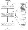
도 3은 컴포넌트 캐리어 특정 SRS 전력 제어를 보인 기본적인 흐름도이다.
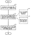
도 4는 캐리어 공통 SRS 전력 제어를 보인 기본적인 흐름도이다.
도 5는 SRS가 다중 안테나 포트(또는 계층)를 통해 전송되는 구성의 SRS 전력 제어를 보인 기본적인 흐름도이다.Further details of the invention will be understood from the following description, given by way of example in conjunction with the accompanying drawings.
1 illustrates a Long Term Evolution (LTE) wireless communication system / access network.
2 is a block diagram of an LTE wireless communication system.
3 is a basic flow diagram illustrating component carrier specific SRS power control.
4 is a basic flowchart illustrating carrier common SRS power control.
5 is a basic flow diagram illustrating SRS power control in a configuration in which SRSs are transmitted through multiple antenna ports (or layers).
이하에서 사용되는 용어 "무선 송수신 유닛(WTRU)"은 비제한적인 예를 들자면 사용자 설비(UE), 이동국, 고정식 또는 이동식 가입자 유닛, 페이저, 셀룰러 전화기, 개인용 정보 단말기(PDA), 컴퓨터, 또는 무선 환경에서 동작할 수 있는 임의의 다른 유형의 사용자 장치를 포함한다. 이하에서 사용되는 용어 "기지국"은 비제한적인 예를 들자면 노드-B, 진화형(evolved) 노드B(eNodeB 또는 eNB), 사이트 제어기, 접근점(AP), 또는 무선 환경에서 동작할 수 있는 임의의 다른 유형의 인터페이스 장치를 포함한다.The term " wireless transmit / receive unit (WTRU) " as used below includes, but is not limited to, user equipment (UE), mobile station, fixed or mobile subscriber unit, pager, cellular telephone, personal digital assistant (PDA), computer, or wireless. Any other type of user device capable of operating in an environment. The term "base station", as used below, includes, but is not limited to, Node-B, evolved NodeB (eNodeB or eNB), site controller, access point (AP), or any that may operate in a wireless environment. Other types of interface devices.
도 1은 진화형 범용 지상 라디오 액세스 네트워크(E-UTRAN)(205)를 포함한 롱텀 에볼루션(LTE) 무선 통신 시스템/액세스 네트워크(200)를 보인 것이다. E-UTRAN(205)은 수 개의 진화형 노드-B(eNB)(220)를 포함한다. WTRU(210)는 eNB(220)와 통신한다. eNB(220)는 X2 인터페이스를 이용하여 서로 인터페이스 접속한다. 각 eNB(220)는 S1 인터페이스를 통해 이동성 관리 엔티티(MME)/서빙 게이트웨이(S-GW)(230)와 인터페이스 접속한다. 비록 도 1에는 하나의 WTRU(210)와 3개의 eNB(220)가 도시되어 있지만, 임의 조합의 무선 및 유선 장치가 무선 통신 시스템 액세스 네트워크(200)에 포함될 수 있다는 것을 이해하여야 한다.1 shows a long term evolution (LTE) wireless communication system / access network 200 including an evolved universal terrestrial radio access network (E-UTRAN) 205. E-UTRAN 205 includes several evolved Node-B (eNB) 220. The WTRU 210 communicates with the eNB 220. The eNBs 220 interface with each other using an X2 interface. Each eNB 220 interfaces with a mobility management entity (MME) / serving gateway (S-GW) 230 via an S1 interface. Although one WTRU 210 and three eNBs 220 are shown in FIG. 1, it should be understood that any combination of wireless and wired devices may be included in the wireless communication system access network 200.
도 2는 WTRU(210), eNB(220) 및 MME/S-GW(230)를 포함한 LTE 무선 통신 시스템(300)의 예시적인 블록도이다. 도 2에 도시한 바와 같이, WTRU(210), eNB(220) 및 MME/S-GW(230)는 MIMO 및 캐리어 집성 기술을 이용하여 SRS 전송 방법을 수행하도록 구성된다.2 is an exemplary block diagram of an LTE
전형적인 WTRU에서 나타나는 컴포넌트 외에, WTRU(210)는 선택적 결합 메모리(322)를 구비한 프로세서(316), 적어도 하나의 송수신기(314), 선택사항인 배터리(320) 및 안테나(318)를 포함한다. 프로세서(316)는 MIMO 및 캐리어 집성 기술을 이용하여 SRS 전송 방법을 수행하도록 구성된다. 송수신기(314)는 프로세서(316) 및 안테나(318)와 통신하여 무선 통신의 송신 및 수신을 행한다. WTRU(210)에서 배터리(320)를 사용하는 경우에, 배터리는 송수신기(314) 및 프로세서(316)에 전원을 공급한다.In addition to the components shown in a typical WTRU, the WTRU 210 includes a
전형적인 eNB에서 나타나는 컴포넌트 외에, eNB(220)는 선택적 결합 메모리(315)를 구비한 프로세서(317), 송수신기(319) 및 안테나(321)를 포함한다. 프로세서(317)는 (MIMO) 및 캐리어 집성 기술을 이용하여 SRS 기능성을 지원하도록 구성된다. 송수신기(319)는 프로세서(317) 및 안테나(321)와 통신하여 무선 통신의 송신 및 수신을 행한다. 프로세서는 일반적으로 i) 어떤 WTRU가 SRS를 전송할 것인지를 결정하고, ii) SRS 전송을 위한 각 WTRU의 주파수 및 시간에 있어서의 할당 및 SRS 전송의 유형을 결정하고 이 정보를 WTRU에 통신하며, iii) SRS 측정 정보를 수신하고, iv) SRS 정보를 처리하여 스케줄러가 스케줄링 결정(예를 들면, UL 리소스를 WTRU에 지정하는 것)을 할 수 있도록 스케줄러(역시 프로세서(317)에 상주함)에 통보하도록 구성된다. eNB(220)는 선택적 결합 메모리(334)를 구비한 프로세서(333)를 포함하는 이동성 관리 엔티티/서빙 게이트웨이(MME/S-GW)(230)에 접속된다.In addition to the components shown in a typical eNB, the eNB 220 includes a
LTE(즉, LTE 릴리즈 8/9)에서는 단일 안테나 및 단일 캐리어를 이용한 PUCCH, PUSCH 또는 사운딩 레퍼런스 신호(SRS)의 단일 전송이 있다. WTRU는 SRS와 PUCCH 포맷 2/2a/2b 전송이 동일 서브프레임에서 동시에 발생할 때는 SRS를 전송하지 않는다. WTRU는 SRS와 긍정응답/부정응답(ACK/NACK) 및/또는 포지티브 SRS 전송이 동일 서브프레임에서 동시에 발생할 때는 파라미터 동시-AN-및-SRS(Simultaneous-AN-and-SRS)가 참(true)이 아닌 한 SRS를 전송하지 않는다. 상위 계층(higher layer)에 의해 제공되는 파라미터 동시-AN-및-SRS는 WTRU가 하나의 서브프레임 내의 PUCCH 및 SRS에서 ACK/NACK의 전송을 지원하도록 구성되었는지를 결정한다. 만일 WTRU가 하나의 서브프레임 내의 PUCCH 및 SRS에서 ACK/NACK의 전송을 지원하도록 구성되었으면, 셀 특정 SRS 서브프레임에서 WTRU는 단축 PUCCH 포맷을 이용하여 ACK/NACK 및 SR을 전송할 것이고, 여기에서 SRS 심볼에 대응하는 SR 심볼 또는 ACK/NACK는 천공(punctured)된다.In LTE (ie LTE Release 8/9) there is a single transmission of a PUCCH, PUSCH or sounding reference signal (SRS) using a single antenna and a single carrier. The WTRU does not transmit SRS when SRS and PUCCH format 2 / 2a / 2b transmission occur simultaneously in the same subframe. The WTRU may indicate that simultaneous SAN and positive / RSA and / or positive SRS transmissions occur simultaneously in the same subframe, when the parameter simultaneous-AN-and-SRS (Simultaneous-AN-and-SRS) is true. Do not transmit SRS unless otherwise. The parameter simultaneous-AN-and-SRS provided by the higher layer determines whether the WTRU is configured to support the transmission of ACK / NACK in PUCCH and SRS in one subframe. If the WTRU is configured to support the transmission of ACK / NACK in PUCCH and SRS in one subframe, in the cell specific SRS subframe the WTRU will transmit ACK / NACK and SR using the shortened PUCCH format, where the SRS symbol The SR symbol or ACK / NACK corresponding to is punctured.
LTE에 있어서, eNodeB가 각 UL에 대한 주파수-스케줄링의 신뢰할만한 채널 추정을 수행하기 위하여, SRS(및 기타의 채널)의 전송 전력이 제어된다. WTRU가 SRS에 대한 전력 제어(PC)를 지원하게 하는 기능적 필요조건은 뒤에서 나타내었다. 서브프레임 i에서 전송되는 사운딩 레퍼런스 심볼의 WTRU 전송 전력(PSRS)의 설정은 하기 수학식 1로 정의된다.In LTE, the transmit power of the SRS (and other channels) is controlled in order for the eNodeB to perform reliable channel estimation of frequency-scheduling for each UL. The functional requirements for the WTRU to support power control (PC) for SRS are shown below. The setting of the WTRU transmit power P SRS of the sounding reference symbol transmitted in subframe i is defined by
PSRS(i)=min{PMAX, PSRS _ OFFSET+10log10(MSRS)+P0 _ PUSCH(j)+α·PL+f(i)}[dBm]P SRS (i) = min {P MAX , P SRS _ OFFSET + 10log 10 (M SRS ) + P 0 _ PUSCH (j) + αPL + f (i)} [dBm]
수학식 1
상기 수학식에서, KS=1.25일 때, PSRS _ OFFSET는 [-3, 12]dB의 범위에서 1dB 스텝 사이즈로 상위 계층에 의해 반 정적으로(semi-statically) 구성된 4-비트 WTRU 특정 파라미터이다.In the above equation, when K S = 1.25, P SRS _ OFFSET is a 4-bit WTRU specific parameter configured semi-statically by a higher layer with a 1 dB step size in the range of [-3, 12] dB. .
KS=0일 때, PSRS _ OFFSET는 [-10.5, 12]dB의 범위에서 1.5dB 스텝 사이즈로 상위 계층에 의해 반 정적으로 구성된 4-비트 WTRU 특정 파라미터이다.When K S = 0, P SRS _ OFFSET is a 4-bit WTRU specific parameter configured semi-statically by the upper layer with a 1.5 dB step size in the range [-10.5, 12] dB.
MSRS는 다수의 리소스 블록으로 표현되는 서브프레임 i에서의 SRS 전송의 대역폭이다.M SRS is the bandwidth of SRS transmission in subframe i represented by multiple resource blocks.
f(i)는 PUSCH의 현재 전력 제어 조정 상태이다.f (i) is the current power control adjustment state of the PUSCH.
PO _ PUSCH(j)는 파라미터이고, 여기에서 j=1이다.P O _ PUSCH (j) is a parameter where j = 1.
WTRU 전송은 대역외 방출 표준(예를 들면, 인접 채널 누설률(ACLR)) 및 대역내 신호 충실도 필요조건, 예를 들면 에러 벡터 크기(EVM)를 충족시키는 필요조건을 만족시켜야 한다. 전형적으로, 전력 증폭기는 수용가능한 대역외 방출 레벨을 유지하기 위해 선형 또는 거의 선형 범위에서 동작하여야 하고, 선형성의 정도는 파형의 특성에 의해 영향을 받는다. 역사적으로 대역외 방출에서 파형의 영향을 예측하기 위한 성능 지수(figure of merit)로서 피크 전력 대 평균 전력비(PAPR)가 사용되었다. 3GPP에 있어서, PAPR의 경우보다 필요한 전력 증폭기 백오프에서 파형의 영향을 더 잘 반영하기 위해 입방 메트릭(cubic metric; CM)이 고려되고 채용되었다. 하기의 수학식은 CM의 정의일 수 있다.WTRU transmissions must meet out-of-band emission standards (e.g., adjacent channel leak rate (ACLR)) and in-band signal fidelity requirements, e.g., error vector magnitude (EVM). Typically, power amplifiers must operate in a linear or near linear range to maintain an acceptable out-of-band emission level, and the degree of linearity is affected by the characteristics of the waveform. Historically, peak power to average power ratio (PAPR) has been used as a figure of merit to predict the effect of waveforms on out-of-band emissions. In 3GPP, a cubic metric (CM) was considered and employed to better reflect the effect of the waveform on the required power amplifier backoff than in the case of PAPR. The following equation may be a definition of CM.
CM=[20*log10((v_norm 3)rms)-20*log10((v_norm_ref 3)rms)]/1.85 CM = [20 * log10 ((v_norm 3) rms) -20 * log10 ((v_norm_ref 3) rms)] / 1.85
수학식 2Equation 2
위 식에서 v_norm은 입력 신호의 정상 전압 파형이고 v_norm_ref는 레퍼런스 신호(12.2 kbps AMR 스피치)의 정상 전압 파형이며 하기 수학식 3의 관계를 갖는다.In the above equation, v_norm is the normal voltage waveform of the input signal and v_norm_ref is the normal voltage waveform of the reference signal (12.2 kbps AMR speech) and has the relation of Equation 3 below.
20*log10((v_norm_ref 3)rms)=1.52dB 수학식 320 * log10 ((v_norm_ref 3) rms) = 1.52dB Equation 3
예를 들면, 상기 CM 공식을 이용해서, 표 1은 특정 전송 시나리오에 대하여 CM의 90% cdf(누적 밀도 함수) 값을 나타낸다. 표에서 OFDMA의 CM 결과는 참고로 나타낸 것임에 주목하여야 한다. 표에서 알 수 있는 바와 같이, CM은 할당된 라디오 베어(RB 또는 서브캐리어), 변조 유형 등에서 불연속성의 수에 따라 변화한다. 예를 들어서 직교 위상 편이 방식(QPSK) 및 최대 5개의 클러스터를 가진 클러스터화 DFT-S-FDMA(예를 들면, 비접촉 RB 할당)의 CM은 셀 엣지 WTRU에 대하여 QPSK를 사용하는 QPSK의 SC-FDMA에 비하여 1.3dB 이상 증가한다. 비록 CM 분석에 있어서 모든 RB에 대해 동일한 전력이 가정되었지만, CM은 다른 RB간의 전력비(특히, 비접촉 송신에서) 및 송신 안테나의 수의 함수일 수 있다. UL의 미래 LTE 릴리즈에 있어서, PUSCH 및 PUCCH는 동시에 전송될 수 있다(비접촉 RB 할당이 또한 허용될 수 있다). 이러한 전송 조건 하에서, 총 전송된 신호 파형은 더 이상 SC-FDMA의 특성을 갖지 않는다. 이것은 총 전송 신호의 CM(또는 PAPR)을 증가시킬 것이다. 특히, 동일 서브프레임에서 동시 PUSCH 및 PUCCH 전송의 경우에, PUSCH 및 PUCCH의 전력 레벨은 각각 그들의 전력 설정이 독립적이기 때문에 다르게 될 가능성이 매우 높다. 그 경우에, 결과적인 CM은 QPSK에 의한 SC-FDMA보다 2dB 더 높게 증가할 수 있다.For example, using the CM formula, Table 1 shows the 90% cdf (cumulative density function) value of the CM for a particular transmission scenario. It should be noted that the CM results of OFDMA in the table are shown for reference. As can be seen from the table, the CM varies with the number of discontinuities in the assigned radio bear (RB or subcarrier), modulation type, and the like. For example, the CM of orthogonal phase shifting (QPSK) and clustered DFT-S-FDMA with up to five clusters (e.g., contactless RB allocation) may be used for SC-FDMA of QPSK using QPSK for cell edge WTRUs. It is increased by more than 1.3dB. Although the same power is assumed for all RBs in CM analysis, the CM can be a function of the power ratio between different RBs (especially in contactless transmission) and the number of transmit antennas. In future LTE releases of the UL, PUSCH and PUCCH may be transmitted simultaneously (contactless RB allocation may also be allowed). Under these transmission conditions, the total transmitted signal waveform no longer has the characteristics of SC-FDMA. This will increase the CM (or PAPR) of the total transmitted signal. In particular, in the case of simultaneous PUSCH and PUCCH transmission in the same subframe, the power levels of the PUSCH and the PUCCH are very likely to be different because their power settings are each independent. In that case, the resulting CM may increase by 2 dB higher than SC-FDMA by QPSK.
이 경우, 전송 필요조건(예를 들면, EVM 및 ACLR 필요조건)을 충족시키기 위해 WTRU에 대한 2개의 동시 전송의 증가된 CM을 취급할 필요가 있다. UL 신호의 CM의 증가는 전송 필요조건을 충족시키기 위해 최대 전송 전력의 백오프에 대한 WTRU 전력 증폭기를 필요로 할 수 있다. 이것은 Pcmax(또는 Pumax)에 백오프를 적용하는 것과 등가이다. 백오프는 비접촉 할당 RB(또는 RBG)의 수, RB(또는 채널)의 전력비, 변조 유형 등의 함수일 수 있다. 이러한 백오프는 WTRU에서 구현될 수 있다. 대안적으로, eNodeB는 각 WTRU의 정보를 제공할 수 있다.In this case, it is necessary to handle the increased CM of two simultaneous transmissions to the WTRU to meet the transmission requirements (e.g., EVM and ACLR requirements). Increasing the CM of the UL signal may require a WTRU power amplifier for backoff of the maximum transmit power to meet the transmission requirements. This is equivalent to applying a backoff to Pcmax (or Pumax). The backoff may be a function of the number of contactless allocated RBs (or RBGs), the power ratio of the RBs (or channels), the modulation type, and the like. This backoff may be implemented in the WTRU. Alternatively, the eNodeB may provide information for each WTRU.
미래 LTE 릴리즈는 다중 전송 안테나 및 캐리어 집성의 SRS 전송을 또한 지원할 수 있다. WTRU SRS 절차 및 전력 제어의 기능적 필요조건은 이러한 추가적인 특징들을 지원하도록 수정되어야 한다.Future LTE releases may also support SRS transmission of multiple transmit antennas and carrier aggregation. The functional requirements of the WTRU SRS procedure and power control should be modified to support these additional features.
LTE에 있어서, SRS는 다중 전송 안테나로 전송되지 않지만 각각의 지정된 SRS 서브프레임의 단일 안테나를 이용하여 전송된다. 또한, SRS는 다중 컴포넌트 캐리어를 통해 전송되지 않고 항상 단일 캐리어를 이용하여 전송된다. 게다가, 만일 WTRU가 특정 서브프레임에서 SRS를 전송하고 있으면, 다른 채널(예를 들면, PUSCH 및 PUCCH)은 SRS가 전송되는 것과 동일한 SC-FDMA 심볼(즉, 서브프레임의 최종 심볼)에서 동시에 전송되지 않는다.In LTE, the SRS is not transmitted to multiple transmit antennas but is transmitted using a single antenna of each designated SRS subframe. In addition, SRS is always transmitted using a single carrier, rather than on multiple component carriers. In addition, if the WTRU is transmitting an SRS in a particular subframe, other channels (eg, PUSCH and PUCCH) are not transmitted simultaneously in the same SC-FDMA symbol as the SRS is sent (i.e., the last symbol of the subframe). Do not.
LTE UL의 미래 릴리즈는 2개의 새로운 중요한 특징, 즉 다중 입력 다중 출력(MIMO)(최대 4개의 WTRU 전송 안테나를 가진 것) 및 캐리어 집성을 지원할 것이다. 다중 캐리어에서 및/또는 특정 서브프레임의 다중 전송 안테나로부터의 SRS 전송이 가능할 것이다. SRS는 WTRU 안테나 포트마다 규정될 수 있다. 그러나, SM(공간 다중화) MIMO 모드에서, SRS는 미리 부호화되고 계층 특정일 수 있다 - 예를 들면, 4개의 안테나로부터 전송되지만 단지 2개의 안테나 포트만이 사용된다(예상되는 데이터 전송의 공간 계층 당 1개). 만일 SRS 전송 구성(SRS 리소스 할당, SRS 파라미터 및 전력 설정을 포함함)이 부적절하게 수행되면, 전체 UL 전송 시스템은 적절하게 기능하지 않을 것이고 전송 명세(transmission specification)가 부합되지 않을 것이다.Future releases of LTE UL will support two new important features: multiple input multiple output (MIMO) (with up to four WTRU transmit antennas) and carrier aggregation. SRS transmission may be possible in multiple carriers and / or from multiple transmit antennas of a particular subframe. SRS may be defined per WTRU antenna port. However, in SM (spatial multiplexing) MIMO mode, the SRS can be pre-coded and layer specific-for example, transmitted from four antennas but only two antenna ports are used (1 per spatial layer of the expected data transmission). dog). If the SRS transmission configuration (including SRS resource allocation, SRS parameters and power settings) is performed improperly, the entire UL transmission system will not function properly and the transmission specification will not be met.
특히, 사운딩 레퍼런스 신호의 오버헤드는 전송 안테나의 수가 증가(예를 들면 최대 4개까지)함에 따라 특별한 관심사로 된다. 그러므로 오버헤드를 낮게 발생하는 SRS 설계를 갖는 것이 바람직하다. 예를 들면, SRS는 필요할 때만 드물게 및 양호하게 전송될 것이다. 또한, 바람직하게도 오버헤드는 그것으로부터 이익을 갖는 WTRU에 의해서만 아마도 양호한 스케줄러 융통성을 허용하기에 충분한 동적으로 보여진다.In particular, the overhead of the sounding reference signal is of particular concern as the number of transmit antennas increases (eg up to four). Therefore, it is desirable to have an SRS design that generates low overhead. For example, SRS will be transmitted rarely and well only when needed. Also, the overhead is preferably seen dynamically enough to allow good scheduler flexibility only by the WTRUs benefiting from it.
UL MIMO에서, 소정의 WTRU에 대한 직교 SRS는 바람직한 특성을 갖지만 잠재적으로 격한 오버헤드와 함께 나타난다. 비직교 SRS를 또한 사용할 수 있다. 2가지 유형의 SRS를 사용하는 경우, WTRU는 2가지 유형의 SRS를 구별하여야 하고 SRS 유형에 따라서 UL CSI의 다른 해석/규정을 가질 수 있다. 또한, SRS가 LTE 백워드 호환 서브프레임/캐리어에 나타나기 때문에 SRS는 SRS 전송을 위한 서브프레임(의 적어도 일부)를 사용하기에 충분한 리소스일 수 있다.In UL MIMO, orthogonal SRS for a given WTRU has desirable characteristics but appears with potentially severe overhead. Non-orthogonal SRS can also be used. When using two types of SRS, the WTRU must distinguish between the two types of SRS and may have different interpretations / rules of UL CSI depending on the SRS type. In addition, since the SRS appears in an LTE backward compatible subframe / carrier, the SRS may be sufficient resource to use (at least a portion of) a subframe for SRS transmission.
PUCCH에서의 제어 신호 및 PUSCH에서의 데이터의 동시 UL 전송은 동일한 서브프레임의 동일한 컴포넌트 캐리어 내에서 또한 가능하다. PUSCH, PUCCH 및 SRS가 동일한 서브프레임에서 전송될 수 있다. 이 경우, 채널들 사이에서 다중화 규칙이 규정될 수 있다.Simultaneous UL transmission of control signals in the PUCCH and data in the PUSCH is also possible within the same component carrier of the same subframe. PUSCH, PUCCH and SRS may be transmitted in the same subframe. In this case, multiplexing rules may be defined between the channels.
하기의 SRS 파라미터는 상위 계층에 의해 반 정적으로 구성가능한 WTRU 특정으로서 LTE에서 규정된다: i) 전송 콤(comb), ii) 개시 물리 리소스 블록 지정, iii) SRS 전송의 지속기간: 단일 또는 무기한(디스에이블될 때까지), iv) 주기성 및 SRS 서브프레임 오프셋에 대한 SRS 구성 인덱스(ISRS), v) SRS 대역폭, vi) 주파수 호핑 대역폭, 및 vii) 주기적 편이(cyclic shift).The following SRS parameters are defined in LTE as WTRU specific, semi-statically configurable by higher layers: i) transmission comb, ii) initiation physical resource block designation, iii) duration of SRS transmission: single or indefinite ( Until disabled), iv) SRS configuration index (I SRS ) for periodicity and SRS subframe offset, v) SRS bandwidth, vi) frequency hopping bandwidth, and vii) cyclic shift.
안테나 선택이 전송 안테나 선택을 지원하는 WTRU에 대해 인에이블되면, SRS를 한번에 전송하는 WTRU 안테나의 인덱스는 시간 인덱스, 호핑 인에이블/디스에이블 등을 포함하는 몇 가지 파라미터에 기초하여 결정된다.If antenna selection is enabled for a WTRU supporting transmit antenna selection, the index of the WTRU antenna transmitting SRS at one time is determined based on several parameters including time index, hopping enable / disable, and the like.
MIMO에 있어서, WTRU에 대한 SRS의 수는 전송 안테나 또는 안테나 포트(WTRU 특정)의 수만큼 크다. 다른 실시예에 있어서, SRS 및/또는 전송 안테나 특정 SRS 파라미터의 수는 WTRU마다 또는 셀 내의 WTRU 그룹마다 상위 계층 시그널링 또는 L1/2 시그널링(즉, PDCCH에서)에 의해 구성될 수 있다. 만일 이들이 PDCCH에서 시그널링되면, 시그널링을 지원하기 위해 새로운 DCI 포맷이 필요하다. 예를 들면, 다중 안테나를 이용한 비주기적 SRS 전송을 요청(또는 계획)하기 위해, SRS 요청 비트가 PDCCH에 포함될 수 있다. 이러한 구성은 안테나 단위로 또는 계층 기준(layer basis) 단위로 SRS 전송을 관련시킬 수 있다.For MIMO, the number of SRSs for a WTRU is as large as the number of transmit antennas or antenna ports (WTRU specific). In another embodiment, the number of SRS and / or transmit antenna specific SRS parameters may be configured by higher layer signaling or L1 / 2 signaling (ie, in the PDCCH) per WTRU or per WTRU group in a cell. If they are signaled on the PDCCH, a new DCI format is needed to support signaling. For example, to request (or plan) aperiodic SRS transmission using multiple antennas, an SRS request bit may be included in the PDCCH. Such a configuration may relate SRS transmission on an antenna basis or on a layer basis basis.
캐리어 집성에 있어서, 어떤 캐리어 SRS가 전송되는지에 대한 선택이 또한 신호될 필요가 있다. WTRU는 그 구성된 캐리어 모두에서 SRS를 동시에 전송할 수 있다. 다른 실시예에 있어서, WTRU는 그 캐리어의 부분집합에서 선택적으로 전송할 수 있다. 다른 실시예에 있어서, WTRU는 한번에 하나의 캐리어에서만 전송할 수 있다. UL 캐리어 특정 SRS 파라미터는 WTRU마다 또는 셀 내의 WTRU 그룹마다 상위 계층 시그널링 또는 L1/2 시그널링(즉, PDCCH에서)에 의해 구성될 수 있다. 또한 부대역 SRS는 다중 캐리어에 걸쳐서 또는 캐리어마다 제어될 수 있다. 예를 들면, UL 고정(anchor) 캐리어는 광대역 SRS 전송을 가질 수 있고, 다른 비고정 캐리어는 협대역 SRS 전송을 사용할 수 있다.In carrier aggregation, the choice of which carrier SRS is to be transmitted also needs to be signaled. The WTRU may transmit SRS simultaneously on all of its configured carriers. In another embodiment, the WTRU may selectively transmit on a subset of its carriers. In another embodiment, the WTRU may transmit on only one carrier at a time. The UL carrier specific SRS parameter may be configured by higher layer signaling or L1 / 2 signaling (ie, in the PDCCH) per WTRU or per WTRU group in a cell. Subband SRS may also be controlled over multiple carriers or per carrier. For example, UL anchor carriers may have wideband SRS transmissions, and other unfixed carriers may use narrowband SRS transmissions.
더 나아가, LTE의 미래 릴리즈로서, UL은 컴포넌트 캐리어에서 비접촉 리소스 할당(즉, 클러스터 기반 DFT-OFDMA)을 지원하고, SRS 리소스 할당은 주파수 영역 스케줄링, 예를 들면 더 가능성있는 SRS 대역폭을 위해 적어도 관심대상 주파수 대역을 커버하도록 충분히 융통성이 있어야 한다. 다운링크 시그널링(예를 들면, PDCCH)은 SRS 전송을 위한 새로운 파라미터를 또한 지원할 수 있어야 한다.Furthermore, as a future release of LTE, UL supports contactless resource allocation (i.e. cluster-based DFT-OFDMA) in component carriers, and SRS resource allocation is at least of interest for frequency domain scheduling, e.g. more likely SRS bandwidth. It must be flexible enough to cover the target frequency band. Downlink signaling (eg, PDCCH) must also be able to support new parameters for SRS transmission.
SRS의 전송 전력 제어는 기본적으로, PO _ PUSCH(j), f(i) 및 α를 포함하는 SRS의 몇 가지 중요한 전력 제어(PC) 파라미터가 PUSCH 전력 제어에 대한 것과 동일하다는 점에서, SRS 전송의 정확한 대역폭(BW)을 보상하는 PUSCH의 전송 전력 제어를 따른다. 현재의 LTE 표준을 넘어서는 복수의 이슈가 다루어져야 한다. 이들의 일부에 대해서는 뒤에서 설명한다.The transmit power control of the SRS is basically SRS in that some important power control (PC) parameters of the SRS, including P O _ PUSCH (j), f (i) and α, are the same as for PUSCH power control. Follow the transmit power control of the PUSCH to compensate for the exact bandwidth (BW) of the transmission. Multiple issues beyond the current LTE standard must be addressed. Some of these are described later.
미래의 LTE 릴리즈가 서브프레임 내의 동시 PUSCH/PUCCH를 지원한다는 사실을 고려하면, SRS가 PUSCH의 종단에서 스케줄되는 것 및 SRS와 PUCCH의 결합된 필요 전력이 PMAX의 값을 초과하는 것이 가능하다.Given the fact that future LTE releases support simultaneous PUSCH / PUCCH in a subframe, it is possible that the SRS is scheduled at the end of the PUSCH and the combined required power of the SRS and PUCCH exceeds the value of P MAX .
UL MIMO(예를 들면, 최대 4개의 안테나까지)에 의해, 만일 다중 전송 안테나를 통한 동시 SRS 전송이 발생하면, SRS의 전송 전력 밀도는 안테나의 수가 증가함에 따라 낮아지고, 이것은 eNodeB에서의 채널 추정을 감퇴시킬 수 있다. PUSCH 전송을 위한 각종 MIMO 옵션(SM MIMO, 송신기(Tx) 다이버시티, 및 빔형성(BF)/단일 안테나 포트 전송을 포함함)이 또한 있을 수 있다. 다중 안테나에 의한 SRS 전송은 또한 결정론적(또는 반 정적)일 수 있다. 그 경우, 예를 들면 안테나 단위 또는 계층 단위(아마도 미리 부호화된 것)의 SRS 전송에 따라서 PUSCH의 다른 MIMO 옵션을 위해 다른 PSRS _ offset 값이 필요할 수 있다. 계산된 SRS 전력이 최대 전력(PMAX)을 초과한 때, 적당한 WTRU 절차가 필요하다. 예를 들면, 전송 안테나 드롭핑 기술, SRS 대역폭 조정, 다중 안테나를 통한 SRS 전력 감소 등이 필요하다.With UL MIMO (eg, up to four antennas), if simultaneous SRS transmission via multiple transmit antennas occurs, the transmit power density of the SRS is lowered as the number of antennas increases, which is a channel estimate at the eNodeB. Can be reduced. There may also be various MIMO options for PUSCH transmission (including SM MIMO, transmitter (Tx) diversity, and beamforming (BF) / single antenna port transmission). SRS transmission by multiple antennas may also be deterministic (or semi-static). In that case, for example according to the SRS transmission of the antenna unit or a unit layer (probably a pre-coding) may require a different P SRS _ offset value for the other option of a MIMO PUSCH. When the calculated SRS power exceeds the maximum power P MAX , an appropriate WTRU procedure is needed. For example, transmit antenna dropping techniques, SRS bandwidth adjustment, and SRS power reduction through multiple antennas are needed.
주파수 영역에서, SRS 전송은 주파수 영역 스케줄링을 위해 관심이 있고 사운딩을 위해 충분히 광대역인 주파수 대역을 커버하여야 한다. 그러나, 광대역 SRS 전송은 비교적 낮은 수신 전력 밀도를 유도할 수 있고, 이것은 eNodeB에서 채널 품질 추정을 감퇴시킬 수 있다. 이것은 다중 캐리어가 UL 전송을 위해 전체로서 사용되는 UL 캐리어 집성에서 훨씬 나쁘게 될 것이다.In the frequency domain, SRS transmissions should cover frequency bands that are of interest for frequency domain scheduling and are sufficiently wideband for sounding. However, wideband SRS transmission can lead to relatively low received power density, which can degrade channel quality estimation at the eNodeB. This will be much worse in UL carrier aggregation where multiple carriers are used as a whole for UL transmission.
UL 캐리어 집성에 있어서, SRS 전송을 위한 최대 WTRU 전력은 컴포넌트 캐리어마다 규정될 수 있다. 하기의 기본 오버헤드 축소 및 전력 설정 접근법은 다중 안테나 및 캐리어 집성에 의한 SRS 전송을 제공한다.For UL carrier aggregation, the maximum WTRU power for SRS transmission may be defined per component carrier. The basic overhead reduction and power setting approach below provides SRS transmission with multiple antennas and carrier aggregation.
SRS 오버헤드 축소/관리 기술은 UL MIMO 및/또는 캐리어 집성에 적용될 수 있다. 예를 들면, SRS는 필요할 때(즉, eNB로부터의 SRS 요청 비트에 의한 비주기적 또는 계획된 SRS 전송)에만 드물게(시간 및/또는 주파수 영역에서) 및 양호하게 전송될 수 있다. 또한, 양호하게, 오버헤드는 그것으로부터 이익이 있는 WTRU에 의해서 및 양호한 스케줄러 융통성을 허용하도록 충분한 동적으로 보여질 뿐이다.SRS overhead reduction / management techniques may be applied to UL MIMO and / or carrier aggregation. For example, SRS may be transmitted infrequently (in time and / or frequency domain) and only when needed (ie, aperiodic or planned SRS transmission by SRS request bits from eNB). Also, preferably, the overhead is only seen dynamically by the WTRU that benefits from it and enough to allow for good scheduler flexibility.
SRS는 WTRU 안테나 포트 단위로(예를 들면, {0, 1, 2, 3}) 및/또는 UL 캐리어 단위로 규정/구성될 수 있다. SM MIMO 모드에 있어서, SRS는 계층 특정 - 예를 들면, 4개의 안테나로부터 전송될 수 있지만 단지 2개의 안테나 포트(예상된 데이터 전송의 공간 계층 당 1개)로만 전송될 수 있다. UL(SU)-MIMO에 있어서, 주어진 WTRU에 대한 직교 SRS는 바람직한 특성을 갖지만 잠재적으로 격한 오버헤드와 함께 나타난다. 미래 LTE 릴리즈에서 SRS의 직교 특성은 시분할 다중화(TDM), 주파수 분할 다중화(FDM), 및/또는 코드 분할 다중화(CDM) 기술을 통하여 달성될 수 있다. 상기 기술들의 2개 이상이 TDM+CDM, TDM+FDM, CDM+FDM 등과 같이 결합될 수 있다는 점을 이해하여야 한다.SRS may be defined / configured on a WTRU antenna port basis (eg {0, 1, 2, 3}) and / or on a UL carrier basis. In the SM MIMO mode, the SRS can be transmitted from layer specific-for example, from four antennas but only to two antenna ports (one per spatial layer of the expected data transmission). For UL (SU) -MIMO, the orthogonal SRS for a given WTRU has desirable properties but appears with potentially severe overhead. In future LTE releases, the orthogonal nature of SRS may be achieved through time division multiplexing (TDM), frequency division multiplexing (FDM), and / or code division multiplexing (CDM) techniques. It should be understood that two or more of the above techniques may be combined such as TDM + CDM, TDM + FDM, CDM + FDM and the like.
CDM 실시예에 있어서, 다중 전송 안테나용의 직교 SRS를 발생하기 위해 다른 위상 회전(즉, 주기적 편이)을 사용할 수 있다. 이 경우, 다른 안테나에 다른 주기적 편이를 지정함으로써, 다중 전송 안테나로부터의 동시 SRS 전송이 수행될 수 있다. 그러나, SRS는 직교성을 유지하기 위해 동일한 주파수 대역에 걸쳐져야 한다. 대안적으로, (직교 커버 부호를 이용하여) 직교식으로 부호화된 SRS는 각 UL Tx 안테나로부터 동시에 전송된다(여기에서 많은 종류의 직교 및 의사 직교(quasi-orthogonal) 부호가 사용될 수 있다). 다른 집합의 위상 회전이 다른 WTRU에 지정되어 다른 WTRU로부터의 SRS 전송이 또한 서로 직교하게 한다.In the CDM embodiment, other phase rotations (ie, periodic shifts) may be used to generate orthogonal SRS for multiple transmit antennas. In this case, simultaneous SRS transmission from multiple transmit antennas can be performed by assigning different periodic shifts to different antennas. However, SRSs must span the same frequency band to maintain orthogonality. Alternatively, orthogonally coded SRSs (using orthogonal cover codes) are transmitted simultaneously from each UL Tx antenna (where many kinds of orthogonal and quasi-orthogonal codes may be used). Different sets of phase rotations are assigned to different WTRUs so that SRS transmissions from other WTRUs are also orthogonal to each other.
FDM 실시예에 있어서, 다른 안테나 포트(또는 계층)를 통한 SRS 전송은 다른 주파수/시간 리소스 그리드에서 실행될 수 있다. 이것은 동일한 주파수 대역(또는 SRS 대역폭)을 커버하기 위한 전송을 요구하지 않는다. 즉, 각 안테나 포트(또는 계층)에 대하여 다른 SRS 주파수 대역폭이 구성될 수 있다.In an FDM embodiment, SRS transmissions on other antenna ports (or layers) may be performed on different frequency / time resource grids. This does not require transmission to cover the same frequency band (or SRS bandwidth). That is, different SRS frequency bandwidths can be configured for each antenna port (or layer).
상기 FDM 실시예는 다음과 같이 구현될 수 있다. 비월주사 SRS가 사용될 수 있다. 이 실시예에서, 각 안테나는 SRS 전송에 지정된 톤(tone)/서브캐리어의 부분집합으로만 전송한다(예를 들면, 4개의 Tx 안테나를 구비한 WTRU에 대해 각 톤으로 전체 PUSCH 영역에 걸쳐 전송하도록 구성된 SRS에 있어서, 1번째, 5번째, 9번째,...톤/서브캐리어는 안테나 1로부터 전송되도록 지정되고, 2번째, 6번째, 10번째,...톤/서브캐리어는 안테나 2로부터 전송되도록 지정되는 등으로 지정된다). 안테나 지정은 서브프레임 번호(SFN) 의존성일 수 있고, 그래서 각 안테나에 사용되는 톤의 회전(호핑)이 있다(예를 들면, TTI1에서 안테나 1은 톤 1, 5, 9,...를 사용하고, TTI2에서 안테나 1은 톤 2, 6, 10을 사용한다).The FDM embodiment may be implemented as follows. Interlaced SRS may be used. In this embodiment, each antenna transmits only a subset of tones / subcarriers specified for SRS transmission (e.g., transmits over the entire PUSCH region in each tone for a WTRU with four Tx antennas). For the SRS, the first, fifth, ninth, ... tones / subcarriers are designated to be transmitted from
TDM 실시예에 있어서, WTRU는 다른 서브프레임 오프셋을 이용하여 다른 전송 안테나로부터 SRS를 전송한다. 이것은 상위 계층에 의해 구성될 수 있다. 대안적으로, 안테나 포트 n(또는 계층 n)(여기에서 n=0, 1, 2, ...Nt이다)에 대한 SRS는 예를 들면 mod(x, Nt)=n을 만족시키는 SRS 서브프레임 x에서 전송된다. 대안적으로, SRS 전송은 최종 2개의 SC-FDMA 또는 DFT-확산-OFDMA 심볼(대안적으로, 주어진 SRS 서브프레임의 각 슬롯의 최종 SC-FDMA 심볼)에서 일어날 수 있다. 만일 WTRU에서 2개의 Tx 안테나를 사용하면, SRS 구성 중의 하나는 하나의 안테나용의 SRS가 최종 심볼에서 전송되고, 다른 안테나용의 SRS가 제2의 최종 심볼에서 전송되는 것이다. 만일 WTRU에서 4개의 Tx 안테나를 사용하면, SRS 구성 중의 하나는 2개의 Tx 안테나용의 SRS가 최종 심볼에서 전송되고, 다른 2개의 안테나용의 SRS가 제2의 최종 심볼에서 전송되는 것이다.In a TDM embodiment, the WTRU transmits SRS from different transmit antennas using different subframe offsets. This may be configured by higher layers. Alternatively, the SRS for antenna port n (or layer n) (where n = 0, 1, 2, ... Nt) is an SRS subframe that satisfies mod (x, Nt) = n, for example. Sent at x Alternatively, SRS transmission may occur in the last two SC-FDMA or DFT-spread-OFDMA symbols (alternatively, the last SC-FDMA symbol in each slot of a given SRS subframe). If two Tx antennas are used in the WTRU, one of the SRS configurations is that the SRS for one antenna is sent in the last symbol and the SRS for the other antenna is sent in the second last symbol. If the WTRU uses four Tx antennas, one of the SRS configurations is that the SRS for the two Tx antennas is sent in the last symbol and the SRS for the other two antennas is sent in the second last symbol.
백워드 호환성(backward compatibility)을 위하여, 단일 전송 안테나만을 지원하는 WTRU가 또한 지원되어야 한다. 백워드 호환성은 예를 들면 단일 안테나 포트(또는 계층)를 통한 하나의 SRS 전송이 주어진 SRS 서브프레임에서만 이루어지는 것처럼 위에서 설명한 TDM 기술에 의해 달성될 수 있다. 대안적으로 레가시 LTE WTRU는 MIMO 기술을 이용하는 미래 LTE 릴리즈 WTRU와 동시에 동작하여 레가시 WTRU가 LTE에서 규정된 대로 SRS를 전송하고 미래 LTE 릴리즈 WTRU가 LTE 백워드 호환 캐리어로 SRS를 전송하게 할 수 있다.For backward compatibility, WTRUs that support only a single transmit antenna should also be supported. Backward compatibility may be achieved by the TDM technique described above, for example, as if one SRS transmission through a single antenna port (or layer) would only occur in a given SRS subframe. Alternatively, legacy LTE WTRUs may operate concurrently with future LTE release WTRUs using MIMO technology to allow legacy WTRUs to transmit SRS as defined in LTE and future LTE release WTRUs to transmit SRS on LTE backward compatible carriers.
WTRU가 단일 전송 안테나만을 지원하면, WTRU는 LTE와 관련하여 SRS 서브프레임, SRS 주파수 영역, 기타 SRS 파라미터 등을 포함한 동일한 리소스 할당을 공유할 수 있다. 만일 WTRU가 다중 전송 안테나를 지원하면, WTRU는 LTE SRS에 대하여 동일한 SRS 서브프레임을 사용할 수 있지만, 추가의 SRS 리소스(SRS 대역폭을 포함한다)가 상기 제안한 다중화 기술 중의 하나에 의하여 공유될 수 있다. 예를 들어서, 미래 LTE 릴리즈는 상기 TDM 기술(예를 들면 한번에 하나의 SRS)을 이용하여 전송되지만 더욱 빈번하게(예를 들면 매 2, 4, 6, 8 또는 10 밀리초(msec)마다) 전송되는 SRS를 가질 수 있다. 예를 들어서 10 밀리초 SRS 주기로 4개의 안테나 포트를 통한 SRS 전송의 경우에, SRS 주기 시간(모두 4개의 SRS를 전송하는 것)은 40 밀리초이다.If the WTRU supports only a single transmit antenna, then the WTRU may share the same resource allocation, including SRS subframes, SRS frequency domains, other SRS parameters, etc. with respect to LTE. If the WTRU supports multiple transmit antennas, the WTRU may use the same SRS subframe for LTE SRS, but additional SRS resources (including SRS bandwidth) may be shared by one of the proposed multiplexing techniques. For example, future LTE releases are transmitted using the TDM technology (e.g. one SRS at a time) but more frequently (e.g. every 2, 4, 6, 8 or 10 milliseconds (msec)). May have an SRS. For example, in the case of SRS transmission through four antenna ports in a 10 millisecond SRS period, the SRS cycle time (which transmits all four SRSs) is 40 milliseconds.
캐리어 부분집합 SRS 전송 기술이 사용될 수 있다. 캐리어 부분집합 SRS 전송 시나리오에서는 UL 캐리어의 부분집합만이 주어진 시간 간격동안 안테나 포트의 SRS를 전송한다(예를 들면, 전송 시간 간격(TTI), 프레임, 서브프레임 ...). 부분집합의 사이클은 특정의 기간 내의 모든 UL 캐리어를 커버하여야 한다. 예를 들어서 5개의 UL 캐리어가 있다고 가정하자. 부분집합 사이클 A는 SRS 서브프레임에서 하기의 캐리어 부분집합을 전송할 수 있다:Carrier subset SRS transmission techniques may be used. In the carrier subset SRS transmission scenario, only a subset of the UL carriers transmits the SRS of the antenna port for a given time interval (eg, transmission time interval (TTI), frame, subframe ...). The subset's cycle must cover all UL carriers within a certain time period. For example, suppose there are five UL carriers. Subset cycle A may send the following carrier subset in an SRS subframe:
[캐리어1U, 캐리어2U], [캐리어3U, 캐리어4U], [캐리어5U, 캐리어1U], [캐리어2U, 캐리어3U] 및 [캐리어4U, 캐리어5U].[Carrier 1U, carrier 2U], [carrier 3U, carrier 4U], [carrier 5U, carrier 1U], [carrier 2U, carrier 3U] and [carrier 4U, carrier 5U].
부분집합 사이클 B는 하기와 같은 수 있다:Subset cycle B may be as follows:
[캐리어1U, 캐리어2U, 캐리어3U], [캐리어4U, 캐리어5U, 캐리어1U], [캐리어2U, 캐리어3U, 캐리어4U], [캐리어5U, 캐리어1U, 캐리어2U] 및 [캐리어3U, 캐리어4U, 캐리어5U].[Carrier 1U, carrier 2U, carrier 3U], [carrier 4U, carrier 5U, carrier 1U], [carrier 2U, carrier 3U, carrier 4U], [carrier 5U, carrier 1U, carrier 2U] and [carrier 3U, carrier 4U] , Carrier 5U].
다른 사이클/부분집합이 또한 사용될 수 있다. 사이클과 부분집합은 미리정해질 수 있고, 구성가능하고 또는 시그널링될 수 있다.Other cycles / subsets may also be used. Cycles and subsets can be predefined, configurable or signaled.
부분집합 중첩(overlap)이 있는 캐리어 부분집합 SRS 전송이 또한 사용될 수 있다. 부분집합 중첩이 있는 캐리어 부분집합 SRS 전송 시나리오에서는 UL 캐리어의 부분집합만이 주어진 시간 간격동안 안테나 포트의 SRS를 전송한다(예를 들면, 전송 시간 간격(TTI), 프레임, 서브프레임 ...). 캐리어 부분집합은 서로 중첩할 수 있다. 부분집합 중첩은 부분집합들 간에 중첩된 캐리어들을 향상(enhance)시키기 위해 사용될 수 있다. 부분집합의 사이클은 특정 기간 내의 모든 UL 캐리어를 커버하여야 한다. 예를 들어서 5개의 UL 캐리어가 있다고 가정하자. 부분집합 사이클 A는 하기와 같을 수 있다.Carrier subset SRS transmission with subset overlap may also be used. In a carrier subset SRS transmission scenario with subset overlap, only a subset of UL carriers transmit the SRS of the antenna port for a given time interval (e.g., transmission time interval (TTI), frame, subframe ...) . Carrier subsets may overlap each other. Subset overlap can be used to enhance the overlapped carriers between subsets. The subset's cycle must cover all UL carriers within a particular time period. For example, suppose there are five UL carriers. Subset cycle A may be as follows.
[캐리어1U, 캐리어2U], [캐리어2U, 캐리어3U], [캐리어3U, 캐리어4U] 및 [캐리어4U, 캐리어5U].[Carrier 1U, carrier 2U], [carrier 2U, carrier 3U], [carrier 3U, carrier 4U] and [carrier 4U, carrier 5U].
부분집합 사이클 B는 하기와 같은 수 있다.Subset cycle B may be as follows.
[캐리어1U, 캐리어2U, 캐리어3U], [캐리어3U, 캐리어4U, 캐리어5U][Carrier 1U, carrier 2U, carrier 3U], [carrier 3U, carrier 4U, carrier 5U]
다른 사이클/부분집합/중첩이 또한 사용될 수 있다. 사이클/부분집합/중첩은 미리정해질 수 있고, 구성가능하고 또는 시그널링될 수 있다.Other cycles / subsets / nestings may also be used. Cycles / subsets / nesting can be predefined, configurable or signaled.
부분집합 중첩이 있거나 없는 하이브리드 캐리어 부분집합/전체 집합 SRS 전송이 또한 사용될 수 있다. 이러한 하이브리드 시나리오에 있어서, 제1 집합의 SRS 서브프레임(말하자면 서브프레임 A)에서 모든 UL 캐리어는 안테나 포트에 대한 SRS를 전송하고, 제2 집합의 SRS 서브프레임(말하자면 서브프레임 B)에서 UL 캐리어의 부분집합만이 안테나 포트에 대한 SRS를 전송한다. 캐리어 부분집합은 서로 중첩될 수도 있고 중첩되지 않을 수도 있다. SRS 서브프레임 B에서 SRS를 전송하는 캐리어 부분집합의 사이클은 특정 기간 내의 모든 UL 캐리어를 커버하여야 한다. 예를 들어서 5개의 UL 캐리어가 있다고 가정하자. SRS 서브프레임 A는 하기와 같을 수 있다.Hybrid carrier subset / full aggregate SRS transmission with or without subset overlap may also be used. In this hybrid scenario, all UL carriers in the first set of SRS subframes (ie, subframe A) transmit SRSs for the antenna ports, and the UL carriers in the second set of SRS subframes (ie, subframe B) Only a subset transmits the SRS for the antenna port. Carrier subsets may or may not overlap one another. The cycle of carrier subsets transmitting SRS in SRS subframe B must cover all UL carriers within a particular period. For example, suppose there are five UL carriers. SRS subframe A may be as follows.
[모든 캐리어의 SRS 전송], [캐리어1U], [캐리어2U], [캐리어3U], [캐리어4U] 및 [캐리어5U].[SRS transmission of all carriers], [carrier 1U], [carrier 2U], [carrier 3U], [carrier 4U] and [carrier 5U].
SRS 서브프레임 B는 하기와 같을 수 있다.SRS subframe B may be as follows.
캐리어1U, 캐리어2U, 캐리어3U, 캐리어4U 및 캐리어5U의 캐리어 부분집합에 대한 SRS를 전송한다.SRS for a carrier subset of carrier 1U, carrier 2U, carrier 3U, carrier 4U, and carrier 5U.
SRS 서브프레임 A는 모든 안테나/안테나 포트/계층 또는 안테나/안테나 포트/계층의 부분집합으로부터 모든 캐리어 또는 캐리어의 부분집합의 SRS 전송을 위한 완전한 정보(예를 들면, 채널 상태 정보(CSI))를 획득하기 위해 사용될 수 있다. SRS 서브프레임 A는 특수 목적으로, 예를 들면, 모든 캐리어의 완전한 정보를 획득함에 있어서 캐리어 부분집합 SRS 전송이 지연될 때 사용할 수 있다. SRS 서브프레임 A는 주기적일 수 있고, 주기성은 구성가능하다. SRS 서브프레임 A는 매 N개의 서브프레임에서 전송될 수 있다. SRS 서브프레임 A는 또한 비주기적일 수 있다. SRS는 SRS 비주기적 요청에 따라 전송될 수 있다. 이러한 비주기적 요청은 L1 제어 채널(예를 들면, PDCCH) 또는 상위층 시그널링(예를 들면, 라디오 리소스 제어기(RRC) 시그널링)에 의해 유발될 수 있다.SRS subframe A provides complete information (e.g., channel state information (CSI)) for SRS transmission of all carriers or a subset of carriers from every antenna / antenna port / layer or a subset of antennas / antenna ports / layer. Can be used to obtain. SRS subframe A may be used for special purposes, for example, when carrier subset SRS transmission is delayed in obtaining complete information of all carriers. SRS subframe A may be periodic and periodicity is configurable. SRS subframe A may be transmitted in every N subframes. SRS subframe A may also be aperiodic. SRS may be transmitted according to the SRS aperiodic request. This aperiodic request may be caused by an L1 control channel (eg, PDCCH) or higher layer signaling (eg, radio resource controller (RRC) signaling).
대안적으로, 비직교 SRS를 또한 고려할 수 있다. 만일 2가지 유형의 SRS가 구성되면, WTRU는 그들을 구별할 수 있어야 하고, 아마도 SRS 유형에 따라서 UL CSI의 다른 해석/정의를 가져야 한다.Alternatively, non-orthogonal SRS may also be considered. If two types of SRS are configured, the WTRU should be able to distinguish them and perhaps have different interpretations / definitions of UL CSI depending on the SRS type.
혼합 LTE 릴리즈 시나리오의 SRS 전송에 있어서, LTE WTRU에 대한 백워드 호환성을 유지하기 위해, 미래 LTE 릴리즈 WTRU에 대하여 동일한 파라미터가 구성될 수 있다. 더 나아가, LTE SRS 절차가 WTRU에 또한 적용된다. 그러나, 주어진 서브프레임에서, WTRU가 다중 안테나(또는 안테나 포트)를 통하여 전송할 수 있는 동시 SRS의 수는 N개(예를 들면, N=2)로 제한된다. 만일 안테나의 수가 허용 제한치(N)보다 더 크면, 다른 안테나로부터의 SRS는 TDM(예를 들면, 다른 서브프레임)일 수 있다.In SRS transmission of mixed LTE release scenarios, the same parameters may be configured for future LTE release WTRUs to maintain backward compatibility for LTE WTRUs. Furthermore, LTE SRS procedure also applies to the WTRU. However, in a given subframe, the number of simultaneous SRSs that the WTRU can transmit via multiple antennas (or antenna ports) is limited to N (e.g., N = 2). If the number of antennas is greater than the allowable limit N, the SRS from another antenna may be a TDM (eg, another subframe).
순수한 미래 LTE 릴리즈 시나리오의 SRS 전송에 있어서, 다중 안테나로부터의 SRS는 위에서 언급한 다중화 기술을 이용하여 다중화될 수 있다.In SRS transmission of pure future LTE release scenarios, SRS from multiple antennas can be multiplexed using the multiplexing technique mentioned above.
SRS 전송은 다중 캐리어 시나리오에서 또한 발생할 수 있다. DL 시그널링 오버헤드 관점으로부터, SRS 파라미터의 공통 집합은 서브프레임 오프셋, SRS 전송 주기성, SRS 대역폭 등을 비롯한 모든 할당된 UL 캐리어에 적용될 수 있다. 그러나, SRS를 동시에 운반하는 UL 캐리어의 수가 증가함에 따라서 각 캐리어의 SRS 전송 전력 밀도는 낮아지고, 이것은 UL 채널 품질 추정을 감퇴시킬 수 있다. 따라서, 다중 캐리어를 통한 동시 SRS 전송의 수는 SRS에 이용할 수 있는 WTRU 전송 전력(예를 들면, 전력 헤드룸)에 따라서 결정할 수 있다. 대안적으로, SRS 파라미터는 개별 캐리어에 대해 구성될 수 있다. 이 경우에, 캐리어의 일부 파라미터는 다른 캐리어에 대해 구성된 SRS 파라미터로부터 암시적으로 결정될 수 있다.SRS transmission may also occur in a multi-carrier scenario. From a DL signaling overhead point of view, a common set of SRS parameters may be applied to all assigned UL carriers, including subframe offsets, SRS transmission periodicity, SRS bandwidth, and the like. However, as the number of UL carriers carrying SRS simultaneously increases, the SRS transmit power density of each carrier is lowered, which can degrade the UL channel quality estimate. Thus, the number of simultaneous SRS transmissions on multiple carriers can be determined according to the WTRU transmit power (eg, power headroom) available for SRS. Alternatively, SRS parameters can be configured for individual carriers. In this case, some parameters of the carrier may be implicitly determined from SRS parameters configured for other carriers.
LTE에 있어서, WTRU는 SRS 및 PUCCH 포맷 2/2a/2b 전송이 동일 서브프레임에서 동시에 발생할 때는 SRS를 전송하지 않는다. 그러나, 다중 캐리어 전송에서는 만일 캐리어가 그 시간에 PUCCH를 운반하지 않으면 WTRU가 다른 캐리어를 통해 동일 서브프레임에서 SRS를 전송할 수 있다.In LTE, the WTRU does not transmit SRS when SRS and PUCCH format 2 / 2a / 2b transmissions occur simultaneously in the same subframe. However, in multi-carrier transmission, if the carrier does not carry the PUCCH at that time, the WTRU may transmit the SRS in the same subframe on another carrier.
UL 고정 캐리어는 PUCCH를 전송하기 위해 사용된다. 이 실시예에서, 모든 PUCCH는 하나의 UL 캐리어로 전송될 수 있고 다른 UL 캐리어로 전송되지 않는다. 예를 들면, UE 특정 UL CC는 모든 PUCCH를 운반하도록 반 정적으로 구성된다. SRS는 PUCCH를 운반하는 UL 고정 캐리어(또는 UE 특정 UL 캐리어)가 아닌 동일 서브프레임의 다른 UL 캐리어로 전송될 수 있다. 예를 들어서 만일 고정 캐리어가 캐리어1U로서 표시되면, 비 고정 캐리어는 캐리어2U, 캐리어3U, 캐리어4U 및 캐리어5U로서 표시된다. PUCCH는 정상 CP에 대해 포맷 2/2a(또는 확장된 CP에 대해 포맷 2b)를 이용하여 캐리어1U로 전송된다. SRS는 비 고정 캐리어, 즉, 동일 서브프레임의 캐리어2U, 캐리어3U, 캐리어4U 및 캐리어5U로 전송된다. 대안적으로, SRS와 PUCCH 포맷 2/2a/2b 전송이 UL 캐리어의 동일 서브프레임에서 동시에 발생할 때, WTRU는 UL 캐리어의 PUSCH에서 대응하는 UCI 비트(즉, PUSCH에서의 Rel8 UCI 전송에 대한 폴백)를 전송할 수 있다.The UL fixed carrier is used to transmit the PUCCH. In this embodiment, all PUCCHs may be sent on one UL carrier and not on another UL carrier. For example, the UE specific UL CC is semi-statically configured to carry all PUCCHs. The SRS may be transmitted on another UL carrier of the same subframe rather than the UL fixed carrier (or UE specific UL carrier) carrying the PUCCH. For example, if the fixed carrier is indicated as carrier 1U, the unfixed carrier is indicated as carrier 2U, carrier 3U, carrier 4U and carrier 5U. PUCCH is transmitted to carrier 1U using format 2 / 2a for normal CP (or format 2b for extended CP). The SRS is transmitted to an unfixed carrier, that is, carrier 2U, carrier 3U, carrier 4U and carrier 5U of the same subframe. Alternatively, when the SRS and PUCCH format 2 / 2a / 2b transmissions occur simultaneously in the same subframe of the UL carrier, the WTRU may use the corresponding UCI bits in the PUSCH of the UL carrier (ie, fallback for Rel8 UCI transmission in the PUSCH). Can be transmitted.
하나 이상의 UL 고정 캐리어를 사용할 수 있다. 이 실시예에서, 만일 PUCCH 포맷 2/2a/2b를 사용하면 PUCCH는 2개 이상의 UL 고정 캐리어로 전송되고 SRS는 비 고정 캐리어로 동시에 전송될 수 있다. 예를 들어서 만일 고정 캐리어가 캐리어1U 및 캐리어2U로서 표시되면, 비 고정 캐리어는 캐리어3U, 캐리어4U 및 캐리어5U로서 표시된다. PUCCH는 정상의 주기적 프리픽스(cyclic prefix; CP)에 대해 포맷 2/2a(또는 확장된 CP에 대해 포맷 2b)를 이용하여 캐리어1U 및 캐리어2U로 전송된다. SRS는 비 고정 캐리어, 즉, 동일 서브프레임의 캐리어3U, 캐리어4U 및 캐리어5U로 전송된다.One or more UL fixed carriers may be used. In this embodiment, if PUCCH format 2 / 2a / 2b is used, PUCCH may be transmitted on two or more UL fixed carriers and SRS may be transmitted simultaneously on an unfixed carrier. For example, if a fixed carrier is indicated as carrier 1U and carrier 2U, the unfixed carrier is indicated as carrier 3U, carrier 4U and carrier 5U. PUCCH is transmitted to carrier 1U and carrier 2U using format 2 / 2a (or format 2b for extended CP) for a normal cyclic prefix (CP). The SRS is transmitted on an unfixed carrier, that is, carrier 3U, carrier 4U, and carrier 5U of the same subframe.
SRS 오버헤드는 UL 스케줄링 지정(scheduling assignment; SA)에 "SRS 활성화" 필드를 도입하고 그 다음에 ULSA를 이용하여 새로운 SRS 전송을 구성하고 UL 컴포넌트 캐리어의 기존 SRS 전송을 재구성함으로써 축소될 수 있다. 추가적인 세부는 다중 전송 안테나 및/또는 다중 컴포넌트 캐리어에 SRS가 어떻게 맵되는지를 취급하기 위해 필요하다.SRS overhead can be reduced by introducing a "SRS Activation" field in the UL scheduling assignment (SA) and then configuring the new SRS transmission using the ULSA and reconfiguring the existing SRS transmission of the UL component carrier. Additional details are needed to handle how the SRS is mapped to multiple transmit antennas and / or multiple component carriers.
일 실시예로서, 캐리어 특정 SRS 맵핑/구성을 사용할 수 있다. 이러한 캐리어 특정 SRS 맵핑은 동적 방식 또는 반 정적으로 구성될 수 있다. 예를 들면, 각 UL 컴포넌트 캐리어는 다른 SRS 파라미터를 가질 수 있다. 예를 들면, PUSCH가 스케줄되는 UL 컴포넌트 캐리어는 비활성 UL 컴포넌트 캐리어보더 더 짧은 SRS 주기성 및/또는 더 넓은 SRS 대역폭을 가질 수 있다.As one embodiment, carrier specific SRS mapping / configuration may be used. Such carrier specific SRS mapping may be configured in a dynamic manner or semi-statically. For example, each UL component carrier may have a different SRS parameter. For example, a UL component carrier on which a PUSCH is scheduled may have shorter SRS periodicity and / or wider SRS bandwidth than an inactive UL component carrier.
다른 실시예로서, UL MIMO (전송) 모드 의존 SRS 전송을 사용할 수 있다. UL MIMO 모드(Tx 다이버시티 또는 빔형성 또는 단일 안테나 포트 전송 모드 대 SM MIMO 처럼)에 따라서, SRS 전송 방식(예를 들면, SRS 파라미터)은 SRS 시그널링 오버헤드를 유지하도록 변화한다. 예를 들어서 비 SM MIMO, 예를 들면 단일 안테나 포트 전송 모드의 경우에, WTRU는 다중 안테나용의 다른 SRS 파라미터를 갖도록 구성되어 단일 안테나 포트 전송용으로 사용되는 안테나(또는 안테나 포트)로부터의 SRS 전송이 비사용 안테나(또는 안테나 포트)로부터의 SRS 전송보다 더 빈번하게 및/또는 더 넓게 발생하게 한다.As another embodiment, UL MIMO (transmission) mode dependent SRS transmission may be used. Depending on the UL MIMO mode (such as Tx diversity or beamforming or single antenna port transmission mode versus SM MIMO), the SRS transmission scheme (eg, SRS parameter) changes to maintain SRS signaling overhead. For example, in the case of non-SM MIMO, e.g. single antenna port transmission mode, the WTRU is configured to have different SRS parameters for multiple antennas so that SRS transmissions from an antenna (or antenna port) are used for single antenna port transmission. This occurs more frequently and / or more widely than SRS transmissions from this unused antenna (or antenna port).
다른 실시예로서, 상위 계층에 의한 사전구성(preconfigured) SRS 맵핑을 사용할 수 있다. 이 경우에, eNB는 어떤 구성이 사용될 것인지를 단순히 신호한다.As another embodiment, preconfigured SRS mapping by higher layers may be used. In this case, the eNB simply signals which configuration will be used.
몇 개의 변형체를 사용할 수 있다(대부분 WTRU 특정). 이러한 접근법은 정적, 반 정적 또는 동적일 수 있다. 일부는 스케줄되거나 이벤트 구동형일 수 있다. 각 접근법은 뒤에서 자세히 설명하는 것처럼 낮은 SRS 오버헤드 또는 낮은 SRS 제어 시그널링 오버헤드와 같은 다른 장점을 갖는다.Several variants are available (mostly WTRU specific). This approach can be static, semi-static or dynamic. Some may be scheduled or event driven. Each approach has other advantages, such as low SRS overhead or low SRS control signaling overhead, as detailed below.
WTRU에 대한 SRS의 수는 전송 안테나 또는 안테나 포트(WTRU 특정)의 수와 동일하다. 대안적으로, SRS의 수는 셀 내의 WTRU마다 또는 WTRU 그룹마다 상위층 시그널링 또는 L1/2 시그널링(즉, PDCCH에서)에 의해 구성될 수 있다. 만일 이것이 PDCCH에서 시그널링되면, 그 시그널링을 지원하기 위해 새로운 DCI 포맷이 필요할 수 있다. 컴포넌트 캐리어 내에서 비접촉 리소스 할당(즉, 클러스터 기반 DFT-OFDMA)을 지원하기 위해, SRS 전송이 주파수 영역 내의 광대역(적어도 주파수 영역 스케줄링을 위해 필요한 주파수 대역)을 커버하는 것이 바람직하다.The number of SRSs for a WTRU is equal to the number of transmit antennas or antenna ports (WTRU specific). Alternatively, the number of SRSs may be configured by higher layer signaling or L1 / 2 signaling (ie, in the PDCCH) per WTRU or per WTRU group in the cell. If this is signaled on the PDCCH, a new DCI format may be needed to support that signaling. In order to support contactless resource allocation (ie cluster-based DFT-OFDMA) within the component carrier, it is desirable for the SRS transmission to cover a wideband (at least the frequency band required for frequency domain scheduling) in the frequency domain.
정적 또는 반 정적 SRS 스케줄링을 사용할 수 있다. WTRU 전송 안테나 및/또는 WTRU 카테고리의 수에 따라서, SRS 전송 스케줄링이 결정되고 상위 계층 시그널링을 통해 WTRU에 신호된다. 대안적으로, 동적 SRS 스케줄링(즉, 비주기적 SRS 전송)이 L1 시그널링(즉, PDCCH)을 통해 사용될 수 있다.Static or semi-static SRS scheduling can be used. Depending on the number of WTRU transmit antennas and / or WTRU categories, SRS transmission scheduling is determined and signaled to the WTRU via higher layer signaling. Alternatively, dynamic SRS scheduling (ie, aperiodic SRS transmission) can be used via L1 signaling (ie, PDCCH).
주기적 SRS 전송을 위해, SRS 주기성을 구성할 수 있고 상위 계층으로부터 신호될 수 있다. 주기성은 WTRU 전송 안테나(또는 안테나 포트 또는 계층)의 수의 함수일 수 있다. 다른 안테나(또는 안테나 포트)로부터의 SRS는 다른 주기성을 가질 수 있다. SRS의 위치(즉, 서브프레임 오프셋)는 구성가능하고 상위 계층으로부터 신호될 수 있다. 다른 안테나(또는 안테나 포트)로부터의 SRS는 다른 서브프레임 오프셋을 가질 수 있다. 하나의 안테나로부터의 SRS의 위치는 다른 안테나로부터의 SRS의 위치로부터 암시적으로 결정될 수 있다. 좁은 SRS 대역폭을 사용하는 경우 주파수 호핑 기술이 적용될 수 있다. 각 안테나는 다른 호핑 패턴을 가질 수 있다.For periodic SRS transmission, SRS periodicity can be configured and signaled from higher layers. The periodicity may be a function of the number of WTRU transmit antennas (or antenna ports or layers). SRSs from other antennas (or antenna ports) may have different periodicity. The location of the SRS (ie subframe offset) is configurable and can be signaled from higher layers. SRSs from other antennas (or antenna ports) may have different subframe offsets. The location of the SRS from one antenna may be implicitly determined from the location of the SRS from another antenna. If a narrow SRS bandwidth is used, frequency hopping may be applied. Each antenna may have a different hopping pattern.
UL 캐리어 집성에 있어서, 각 캐리어의 SRS 파라미터는 별도로(즉, 캐리어 특정 SRS 파라미터) 또는 함께(예를 들면 모든(또는 부분집합의) 캐리어에 대한 공통 파라미터) 구성/신호될 수 있다. SRS는 비주기적 요청에 의해 유발될 수 있고 또는 주기적 전송용으로 스케줄될 수 있다. 일 실시예로서, 1 비트가 비주기적 SRS 전송을 위한 "SRS 요청" 비트로서 PDCCH(예를 들면, UL 승인(grant))에 삽입된다. PDCCH(예를 들면 UL 승인)로 운반된 비주기적 SRS 요청은 다중 전송 안테나로부터의 SRS 전송을 유발하기 위해 및/또는 다중 UL 캐리어를 위해 사용될 수 있다. 다른 실시예로서, 기존 PDCCH(예를 들면 UL 승인)의 코드 포인트가 비주기적 SRS 전송을 위한 "SRS 요청"으로서 사용된다.For UL carrier aggregation, the SRS parameters of each carrier may be configured / signaled separately (ie, carrier specific SRS parameters) or together (eg, common parameters for all (or subsets) of carriers). SRS may be triggered by aperiodic requests or may be scheduled for periodic transmission. In one embodiment, one bit is inserted in the PDCCH (eg, a UL grant) as the "SRS Request" bit for aperiodic SRS transmission. Aperiodic SRS requests carried on a PDCCH (eg UL grant) may be used to cause SRS transmissions from multiple transmit antennas and / or for multiple UL carriers. In another embodiment, the code point of an existing PDCCH (eg UL grant) is used as an "SRS request" for aperiodic SRS transmission.
다중 UL 캐리어에 대해 SRS를 유발하기 위한 2가지의 가능한 방법이 있다. 특수 UL 캐리어에 대해 UL 승인(비주기적 SRS 요청을 운반함)을 운반하는 PDCCH는 상기 특수 UL 캐리어에 대한 SRS 전송을 유발하기 위해 사용될 것이다. 예를 들면, SRS 요청 비트(아마도, 및 다른 SRS 파라미터)는 상기 특수 UL 캐리어에 대한 비주기적 SRS 전송을 요청하기 위해 PDCCH에 포함될 수 있다. 대안적으로, 특수 UL 캐리어에 대한 UL 승인(비주기적 SRS 요청을 운반함)을 운반하는 PDCCH는 모든 또는 일부의 UL 캐리어(상위 계층 시그널링으로 사전구성된 것)에 대한 SRS 전송을 유발하기 위해 사용될 것이다.There are two possible ways to induce SRS for multiple UL carriers. A PDCCH carrying a UL grant (which carries an aperiodic SRS request) for a special UL carrier will be used to cause SRS transmission for that special UL carrier. For example, SRS request bits (possibly, and other SRS parameters) may be included in the PDCCH to request aperiodic SRS transmission for the special UL carrier. Alternatively, a PDCCH carrying a UL grant (which carries aperiodic SRS request) for a special UL carrier may be used to cause SRS transmission for all or some of the UL carriers (preconfigured with higher layer signaling). .
SRS는 측정치 또는 NACK 임계치에 의해 유발될 수 있다. 만일 WTRU가 사전 구성된 SRS 할당을 가지면, WTRU는 특정 조건이 부합되지 않는 한 SRS를 보내지 않을 것이다. 이러한 조건은 i) 경로손실(pathloss)이 경로손실 변화 임계치보다 더 크게 변화하는 것, ii) NACK의 수가 NACK 임계치를 초과하는 것(예를 들면, % 및/또는 이동 평균(moving average)), iii) UL 전력 제어가 임계치(예를 들면, dB로 특정된 값) 이상으로 변화하는 것을 포함할 수 있다.SRS can be caused by measurements or NACK thresholds. If the WTRU has a preconfigured SRS assignment, the WTRU will not send an SRS unless certain conditions are met. Such conditions may include: i) changing pathloss greater than the pathloss change threshold, ii) number of NACKs exceeding the NACK threshold (e.g.,% and / or moving average), iii) UL power control may include varying above a threshold (eg, a value specified in dB).
측정은 eNodeB에서 수행되고 SRS는 측정치에 따라서 유발될 수 있다. SRS 전송이 유발되면 그 정보가 WTRU에 보내져서 WTRU가 그에 따라서 SRS를 전송할 수 있다. 만일 SRS 전송이 유발되지 않으면, 그 정보가 또한 WTRU에 보내지고 WTRU는 SRS용으로 비축된 리소스를 재사용하여 다른 정보(예를 들면, 데이터, 제어 등)를 전송할 수 있다.The measurement is performed at the eNodeB and the SRS can be triggered depending on the measurement. When SRS transmission is triggered, the information is sent to the WTRU so that the WTRU can transmit the SRS accordingly. If no SRS transmission is triggered, the information is also sent to the WTRU and the WTRU may reuse the resources reserved for the SRS to transmit other information (eg, data, control, etc.).
LTE에 있어서, 서브프레임 i에서 전송되는 SRS에 대한 WTRU 전송 전력(PSRS)은 하기와 같이 규정된다.In LTE, the WTRU transmit power (PSRS) for the SRS transmitted in subframe i is defined as follows.
PSRS(i)=min{PMAX, PSRS _ OFFSET+10log10(MSRS)+PO _ PUSCH(j)+α·PL(k)+f(i)}[dBm]P SRS (i) = min {P MAX , P SRS _ OFFSET + 10log 10 (M SRS ) + P O _ PUSCH (j) + αPL (k) + f (i)} [dBm]
수학식 4Equation 4
LTE UL 전력 제어는 단지 하나의 캐리어 및 하나의 전송 안테나로 제한된다(UL에는 SU-MIMO가 없다). 미래 LTE 릴리즈에서는 캐리어 집성 및 UL SU-MIMO를 사용할 것이다. SRS 전력 제어의 새로운 명세가 필요하다.LTE UL power control is limited to only one carrier and one transmit antenna (there is no SU-MIMO in the UL). Future LTE releases will use carrier aggregation and UL SU-MIMO. There is a need for a new specification of SRS power control.
일 실시예로서, UL 캐리어 집성은 단일 전송 안테나로 실행될 수 있다. 이 실시예에서는 SRS가 보내진 것(즉, SRS의 존재하에 서브프레임의 최종 심볼)과 동일한 SC-FDMA 심볼에서 동시에 전송되는 PUSCH도 PUCCH도 없는 것으로 가정된다.As one embodiment, UL carrier aggregation may be implemented with a single transmit antenna. In this embodiment, it is assumed that neither PUSCH nor PUSCH are transmitted simultaneously in the same SC-FDMA symbol as the SRS is sent (i.e., the last symbol of the subframe in the presence of the SRS).
일반적으로, WTRU는 주어진 컴포넌트 캐리어에 대하여 비강제(unconstrained) SRS 전력 레벨을 결정할 것이다. WTRU는 컴포넌트 캐리어에 대한 강제 SRS 전력 레벨로서 비강제 SRS 전력 레벨과 컴포넌트 캐리어 기반 최대 전력 레벨 중 더 적은 것을 선택할 것이다. 컴포넌트 캐리어에 대한 SRS 전송 전력 레벨은 강제 SRS 전력 레벨로 설정된다.In general, the WTRU will determine an unconstrained SRS power level for a given component carrier. The WTRU will choose the lesser of an unforced SRS power level and a component carrier based maximum power level as the mandatory SRS power level for the component carrier. The SRS transmit power level for the component carrier is set to the forced SRS power level.
이 시나리오에서, SRS는 UL 캐리어 집성을 지원하는 모드에서 구성된 WTRU에 의해 다중 컴포넌트 캐리어를 통해 동시에 전송된다. SRS 전력 제어를 위한 2가지의 가능한 옵션이 있다. 그 중 하나는 컴포넌트 캐리어 특정 전력 제어용이고 다른 하나는 캐리어 공통 전력 제어용이다. 컴포넌트 캐리어 특정 전력 제어에 있어서, LTE SRS PC 공식은 다음과 같이 파라미터 캐리어 특정의 일부를 가진 UL 캐리어 집성까지 연장된다.In this scenario, the SRS is transmitted simultaneously on multiple component carriers by a WTRU configured in a mode that supports UL carrier aggregation. There are two possible options for SRS power control. One is for component carrier specific power control and the other is for carrier common power control. For component carrier specific power control, the LTE SRS PC formula extends to UL carrier aggregation with some of the parameter carrier specific as follows.
PSRS(i,k)=min{PMAX(k), PSRS _ OFFSET(k)+10log10(MSRS(k))+PO _ PUSCH(j,k)+α(k)·PL(k) +f(i,k)} 수학식 5P SRS (i, k) = min (P MAX (k), P SRS _ OFFSET (k) + 10 log 10 (M SRS (k)) + P O _ PUSCH (j, k) + α (k) (k) + f (i, k)} Equation 5
위 식에서 k는 캐리어 지수이다.Where k is the carrier index.
Pmax(k)는 k번째 컴포넌트 캐리어에 대한, 특히 컴포넌트 캐리어(CC)(또는 CC의 부분집합) 당 하나의 전력 증폭기(PA)에 대한 최대 전력을 나타내는 컴포넌트 캐리어 특정 파라미터이다. 이 경우에, 총 최대 WTRU 전송 전력은 다수의 PA들 중에 동일하게 분배될 수 있다. 즉, Pmax(k)(dB)=Pmax-10*log10(Npa)이고, 여기에서 Npa는 WTRU에서 능동 PA의 수이다. 만일 모든 캐리어에 대해 하나의 PA만이 있으면, Pmax(k)는 총 최대 WTRU 전송 전력(Pmax)과 동일할 수 있다. 이 경우에, 만일 모든 UL 캐리어에 대한 필요한 전송 전력의 합이 Pmax보다 더 크면, 공지된 일부 전력 감소 기술을 사용할 수 있다. 예를 들어서, 개별 캐리어 SRS에 대한 전송 전력은 최대 전력 제약에 부합하도록 고르게 감소될 수 있다. 대안적으로, 개별 캐리어 SRS에 대한 전송 전력은 최대 전력 제약에 부합하도록 상대적으로(예를 들면 개별 SRS 전력에 비례하여) 감소될 수 있다. 대안적으로, SRS 전송중의 하나 또는 일부가 중지(drop)될 수 있다(예를 들면 비 고정 캐리어에서의 SRS). 어떤 SRS 전송(컴포넌트 캐리어(CC)기반으로 및/또는 부대역 기반으로)이 전송되고 어떤 SRS가 중지될 것인지를 결정하기 위해 추가의 기준을 사용할 수 있다. 이 기준은 1) 미리 규정된(구성된) SRS 전송 우선순위, 및 2) 이전 SRS 전송의 이력에 기초를 둘 수 있고, 예를 들면, 제한된 수의 계획된 또는 요청된 SRS CC 및/또는 부대역만이 지원될 때, WTRU는 구성된 모든 SRS가 전송될 때까지 각 SRS 전송 기회에 전송될 구성 SRS를 순환할 것이고, WTRU는 그 다음에 최초 SRS 전송으로 다시 순환할 것이며, 3) WTRU는 가장 유리한 것으로 보이는 CC 및/또는 부대역을 선택할 수 있고, 이용가능한 제한된 전력으로 그 대역에서 SRS를 전송할 수 있다. 중지하는 기술 외에, WTRU는 균일하지 않은 SRS 전력 스케일링을 또한 구현할 수 있다. 균일하지 않은 SRS 전력 스케일링은 또한 상기 기준에 기초할 수 있다.Pmax (k) is a component carrier specific parameter that represents the maximum power for the kth component carrier, in particular for one power amplifier PA per component carrier CC (or subset of CCs). In this case, the total maximum WTRU transmit power may be equally distributed among the multiple PAs. That is, Pmax (k) (dB) = Pmax-10 * log10 (Npa), where Npa is the number of active PAs in the WTRU. If there is only one PA for all carriers, Pmax (k) may be equal to the total maximum WTRU transmit power (Pmax). In this case, some known power reduction techniques can be used if the sum of the required transmit powers for all UL carriers is greater than Pmax. For example, the transmit power for the individual carrier SRS may be evenly reduced to meet the maximum power constraint. Alternatively, the transmit power for the individual carrier SRS can be reduced relatively (eg in proportion to the individual SRS power) to meet the maximum power constraint. Alternatively, one or some of the SRS transmissions may be dropped (eg, SRS on an unfixed carrier). Additional criteria may be used to determine which SRS transmissions (based on component carrier (CC) and / or subband based) are sent and which SRS will be suspended. This criterion may be based on 1) a predefined (configured) SRS transmission priority, and 2) a history of previous SRS transmissions, eg, only a limited number of planned or requested SRS CCs and / or subbands. When this is supported, the WTRU will cycle the configuration SRS to be sent on each SRS transmission opportunity until all configured SRSs have been transmitted, the WTRU will then cycle back to the original SRS transmission, and 3) the WTRU is most advantageous. The visible CC and / or subbands can be selected and SRS can be transmitted in that band with the limited power available. In addition to stopping technology, the WTRU may also implement non-uniform SRS power scaling. Non-uniform SRS power scaling may also be based on the criteria.
PSRS _ OFFSET(k)는 컴포넌트 캐리어 특정 SRS 오프셋이다. PSRS _ OFFSET(k)는 상위 계층에 의해 제공된다. 시그널링 오버헤드를 축소시키기 위해, 각 UL 컴포넌트 캐리어에 대한 PSRS _ OFFSET(k)의 절대치를 신호하는 대신에, 네트워크(eNodeB)는 고정 캐리어에 대해서만 PSRS _ OFFSET의 실제 값을 신호할 수 있지만, 비 고정 캐리어에 대해서는 상대 값을 신호하고, 그 값은 고정 캐리어의 값에 비례한다. 대안적으로 PSRS_OFFSET(k)는 모든 k에 대하여 PSRS _ OFFSET(k)=PSRS _ OFFSET과 같이 캐리어 공통 파라미터일 수 있다.P SRS _ OFFSET (k) is the component carrier specific SRS offset. P SRS _ OFFSET (k) is provided by the higher layer. To reduce the signaling overhead, instead of signaling the absolute value of P SRS _ OFFSET (k) for each UL component carrier, the network eNodeB can signal the actual value of P SRS _ OFFSET only for the fixed carrier, For non-fixed carriers, the relative value is signaled and its value is proportional to the value of the fixed carrier. Alternatively, P SRS_OFFSET (k) may be a carrier common parameter such as P SRS _ OFFSET (k) = P SRS _ OFFSET for all k.
다른 캐리어에서 다른 SRS 대역폭을 가질 수 있고(그러나 안테나마다에 대해서는 가능성이 희박함), 그러므로 캐리어마다 새로운 MSRS(MSRS(k))가 규정될 필요가 있다.Different carriers may have different SRS bandwidths (but unlikely for each antenna) and therefore a new M SRS (M SRS (k)) needs to be defined per carrier.
PO _ PUSCH(j,k)는 캐리어 특정 개방 루프 파라미터이다(이 경우에는 k번째 캐리어에 대한 것). 이것은 다른 캐리어의 다른 타겟(예를 들면, SINR)을 취급하기 위한 것이다. 특히 PO _ PUSCH는 셀 특정 공칭 파라미터(PO _ NOMINAL _ PUSCH)와 WTRU 특정 컴포넌트(PO_UE_PUSCH)의 합으로 구성되고 셀 특정 파라미터(PO _ NOMINAL _ PUSCH)는 모든 캐리어에 대해 공통이기 때문에, 상이한 타겟들이 PO _ UE _ PUSCH(j,k)에 반영된다. 대안적으로, PO_UE_PUSCH를 모든 캐리어에 대해 공통되게 하면서 상이한 타겟들이 PO _ NOMINAL _ PUSCH(j,k)에 반영될 수 있다. 대안적으로 PO _ PUSCH(j,k)가 모든 캐리어에 공통될 수 있다. 이 경우에, PO _ PUSCH(j,k)=PO _ PUSCH(j)이다.P O _ PUSCH (j, k) is a carrier specific open loop parameter (in this case for the k th carrier). This is to handle different targets of different carriers (eg SINR). In particular, since P O _ PUSCH consists of the sum of the cell-specific nominal parameter (P O _ NOMINAL _ PUSCH ) and the WTRU-specific component (P O_UE_PUSCH ), the cell-specific parameter (P O _ NOMINAL _ PUSCH ) is common to all carriers. , Different targets are reflected in P O _ UE _ PUSCH (j, k). Alternatively, different targets may be reflected in P O _ NOMINAL _ PUSCH (j, k) while making P O_UE_PUSCH common to all carriers. Alternatively, the P O _ PUSCH (j, k ) may be common to all carriers. In this case, P O _ PUSCH (j, k) = P O _ PUSCH (j).
경로 손실 보상 계수(PL(k)) 및 단편(fractional) PL 계수(α(k))도 또한 캐리어 특정일 수 있고, 여기에서 PL(k)는 WTRU에서 결정되고 모든 K에 대한 α(k)는 상위 계층 시그널링에 의해 제공된다. 대안적으로, α(k)는 모든 캐리어에 공통일 수 있다.The path loss compensation coefficient PL (k) and the fractional PL coefficient α (k) may also be carrier specific, where PL (k) is determined at the WTRU and α (k) for all K Is provided by higher layer signaling. Alternatively, α (k) may be common to all carriers.
위에서 언급한 바와 같이, WTRU는 단일 컴포넌트 캐리어(Kp)에서 측정을 수행하고 PL(k)=PL(Kp) + ΔPL(k)와 같이 네트워크로부터 신호된 캐리어 특정 오프셋을 이용하여 다른 캐리어에 대한 경로 손실을 유도할 수 있다. 그러나, 이것은 ΔPL(k)에 대한 새로운 상위 계층 시그널링의 도입을 필요로 한다. 그 대신에, 캐리어 특정 경로손실 오프셋은 PO _ PUSCH의 PO _ UE _ PUSCH에 흡수될 수 있다. 이 경우에, PO _ UE _ PUSCH의 범위는 그에 따라서 변화될 필요가 있고, 모든 캐리어에 대해 동일한 PL(k)(즉, PL(k)=PL)를 사용할 수 있다. 이 아이디어는 PUSCH 및 PUCCH용의 PC에 또한 적용될 수 있다.As mentioned above, the WTRU performs measurements on a single component carrier (Kp) and uses a carrier specific offset signaled from the network, such as PL (k) = PL (Kp) + Δ PL (k), for other carriers. Path loss can be induced. However, this requires the introduction of new higher layer signaling for Δ PL (k). Instead, the carrier specific offset path loss can be absorbed in the PUSCH P P O _ O _ _ UE PUSCH. In this case, the range of P O _ UE _ PUSCH needs to be changed accordingly, and the same PL (k) (ie PL (k) = PL) can be used for all carriers. This idea can also be applied to PCs for PUSCH and PUCCH.
(f,k)는 k번째 캐리어에 대한 폐루프 PUSCH 전력 조정 함수(f)이다. 이것은 PUSCH의 TPC 커맨드가 캐리어 특정으로 가정된다는 것을 암시한다. 만일 k번째 캐리어가 다음 SRS 서브프레임에서 전송된 SRS를 갖지만 캐리어에서 이용가능한 f(i,k)가 없으면(이전의 PUSCH 전송이 없기 때문에), f(i,k)에 대하여 복합 f(i)를 사용할 수 있고, 여기에서 복합 f(i)는 다른 f(i,n)(여기에서 n≠k)을 결합함으로써 결정된다. 대안적으로, f(i,k)는 WTRU의 모든 캐리어에 대해 공통일 수 있다. 즉, 모든 k에 대하여 모든 f(i,k)를 결합함으로써 f(i,k)=f(i)로 된다. 예를 들면,(f, k) is the closed loop PUSCH power adjustment function f for the kth carrier. This implies that the TPC command of the PUSCH is assumed to be carrier specific. If the kth carrier has an SRS transmitted in the next SRS subframe but there is no f (i, k) available in the carrier (since there is no previous PUSCH transmission), then a composite f (i) for f (i, k) Can be used, where the compound f (i) is determined by combining another f (i, n), where n ≠ k. Alternatively, f (i, k) may be common for all carriers of the WTRU. That is, f (i, k) = f (i) by combining all f (i, k) for all k. For example,

위 수학식에서 N은 WTRU에 지정된 UL 캐리어의 수이다. 이 옵션은 다른 캐리어가 다른 채널 조건을 갖기 쉬운 비접촉 캐리어 집성이 있는 경우에 바람직하다.In the above equation, N is the number of UL carriers assigned to the WTRU. This option is desirable when there is contactless carrier aggregation where other carriers are likely to have different channel conditions.
도 3은 컴포넌트 캐리어 특정 SRS 전력 제어를 보인 기본적인 흐름도이다. 여기에서 설명하는 기본적인 흐름도는 단지 예시용임을 이해하여야 한다. 예를 들면, 다른 프로그램 진입 및 배출 지점, 타임아웃 함수, 에러 체크 루틴 및 도시를 생략한 기타의 것들은 일반적으로 소프트웨어/하드웨어로 구현될 수 있다. 이러한 하드웨어/소프트웨어는 연속적으로 동작하도록 구현될 수 있다는 것을 또한 이해하여야 한다. 따라서, 시작 블록과 끝 블록은 메인 프로그램, 라이브러리 등에 집적되어 필요에 따라 실행될 수 있는 코드 부분의 논리적인 시작부 및 끝부를 표시하는 것으로 의도된다. 이 예에서, 각 컴포넌트 캐리어의 비강제 SRS 전력 레벨(예를 들면, Pmax(k))은 블록 102에 표시한 것처럼 결정된다. 각 컴포넌트 캐리어의 강제 SRS 전력 레벨은 블록 104에 표시한 것처럼 비강제 SRS 전력 레벨과 컴포넌트 캐리어 기반 최대 전력 레벨 중에서 더 적은 것으로 설정된다. 위에서 설명한 것처럼, 컴포넌트 캐리어 기반 최대 전력 레벨은 i) 블록 110에 표시한 바와 같은 컴포넌트 캐리어 특정 SRS 전력 오프셋, ii) 블록 112에 표시한 바와 같은 컴포넌트 캐리어 특정 SRS 대역폭 파라미터, iii) 블록 114에 표시한 바와 같은 컴포넌트 캐리어 특정 개방 루프 전력 파라미터, iv) 블록 116에 표시한 바와 같은 컴포넌트 캐리어 특정 경로손실 보상 계수, 또는 v) 블록 118에 표시한 바와 같은 컴포넌트 캐리어 특정 폐루프 전력 조정 함수 중의 적어도 하나에 기초한 캐리어 특정 전력 레벨일 수 있다. 각 컴포넌트 캐리어의 SRS 전송 전력 레벨은 블록 106에 표시한 것처럼 선택된 강제 SRS 전력 레벨로 설정된다.3 is a basic flow diagram illustrating component carrier specific SRS power control. It should be understood that the basic flow chart described herein is for illustrative purposes only. For example, other program entry and exit points, timeout functions, error checking routines, and others not shown may generally be implemented in software / hardware. It should also be understood that such hardware / software may be implemented to operate continuously. Thus, the start block and end block are intended to indicate the logical start and end portions of code that may be integrated into the main program, library, etc. and executed as needed. In this example, the unforced SRS power level (eg, Pmax (k)) of each component carrier is determined as indicated in
SRS의 캐리어 공통 전력 제어를 또한 사용할 수 있다. 이것은 SRS PC 관련 파라미터 시그널링 오버헤드를 축소시킬 수 있다. 공통 전송 전력은 하기 수학식과 같이 모든 캐리어에 대해 사용될 수 있다.Carrier common power control of SRS may also be used. This can reduce the SRS PC related parameter signaling overhead. The common transmit power may be used for all carriers as shown in the following equation.
PSRS(i)=min{PMAX, PSRS _ OFFSET+10log10(MSRS)+P0 _ PUSCH(j)+α·PL+f(i)} 수학식 7P SRS (i) = min {P MAX , P SRS _ OFFSET + 10log 10 (M SRS ) + P 0 _ PUSCH (j) + αPL + f (i)}
위 수학식에서 PSRS _ OFFSET, MSRS, PL, f(i)는 각각 모든 UL 캐리어를 통해 각각 결합된 캐리어 공통 파라미터를 나타낸다. 예를 들면,In the above equation, P SRS _ OFFSET , M SRS , PL, and f (i) represent carrier common parameters, respectively, coupled through all UL carriers. For example,

위 수학식에서 N은 WTRU에 지정된 UL 캐리어의 수이다.In the above equation, N is the number of UL carriers assigned to the WTRU.
모든 UL 캐리어에 대한 필요 전송 전력의 합이 Pmax를 초과한 때 전력 감소 기술을 사용할 수 있다. 예를 들면, 개별 캐리어 SRS의 전송 전력은 최대 전력 제약에 부합하도록 고르게 감소될 수 있다. 대안적으로, 개별 캐리어 SRS의 전송 전력은 최대 전력 제약에 부합하도록 상대적으로(예를 들면 개별 SRS 전력에 비례하여) 감소될 수 있다. 대안적으로, SRS 전송중의 하나 또는 일부가 중지될 수 있다(예를 들면 비 고정 캐리어에서의 SRS). 어떤 SRS 전송(컴포넌트 캐리어(CC)기반으로 및/또는 부대역 기반으로)이 전송되고 어떤 SRS가 중지될 것인지를 결정하기 위해 추가의 기준을 사용할 수 있다. 이 기준은 1) 미리 규정된(구성된) SRS 전송의 우선순위, 및 2) 이전 SRS 전송의 이력에 기초를 둘 수 있고, 예를 들면, 제한된 수의 계획된 또는 요청된 SRS CC 및/또는 부대역만이 지원될 수 있을 때, WTRU는 구성된 모든 SRS가 전송될 때까지 각 SRS 전송 기회에 전송될 구성 SRS를 순환할 것이고, WTRU는 최초 SRS 전송으로 다시 순환할 것이며, 3) WTRU는 가장 유리한 것으로 보이는 CC 및/또는 부대역을 선택할 수 있고, 이용가능한 제한된 전력으로 그 대역에서 SRS를 전송할 수 있다. 중지하는 기술 외에, WTRU는 균일하지 않은 SRS 전력 스케일링을 또한 구현할 수 있다. 균일하지 않은 SRS 전력 스케일링은 또한 상기 기준에 기초할 수 있다.Power reduction techniques can be used when the sum of required transmit power for all UL carriers exceeds Pmax. For example, the transmit power of the individual carrier SRS may be evenly reduced to meet the maximum power constraint. Alternatively, the transmit power of the individual carrier SRS can be reduced relatively (eg in proportion to the individual SRS power) to meet the maximum power constraint. Alternatively, one or some of the SRS transmissions may be suspended (eg, SRS on an unfixed carrier). Additional criteria may be used to determine which SRS transmissions (based on component carrier (CC) and / or subband based) are sent and which SRS will be suspended. This criterion may be based on 1) the priority of a predefined (configured) SRS transmission, and 2) the history of previous SRS transmissions, for example, a limited number of planned or requested SRS CCs and / or subbands. When only can be supported, the WTRU will cycle the configuration SRS to be sent on each SRS transmission opportunity until all configured SRSs have been transmitted, the WTRU will cycle back to the original SRS transmission, and 3) the WTRU is most advantageous. The visible CC and / or subbands can be selected and SRS can be transmitted in that band with the limited power available. In addition to stopping technology, the WTRU may also implement non-uniform SRS power scaling. Non-uniform SRS power scaling may also be based on the criteria.
도 4는 캐리어 공통 SRS 전력 제어를 보인 기본적 흐름도이다. 이 예에서, 모든 컴포넌트 캐리어의 비강제 SRS 전력 레벨(예를 들면, Pmax)은 블록 102에 표시한 것처럼 결정된다. 각 컴포넌트 캐리어의 강제 SRS 전력 레벨은 블록 104에 표시한 것처럼 비강제 SRS 전력 레벨과 컴포넌트 캐리어 기반 최대 전력 레벨 중에서 더 적은 것으로 설정된다. 위에서 설명한 것처럼, 컴포넌트 캐리어 기반 최대 전력 레벨은 i) 블록 120에 표시한 바와 같은 캐리어 공통 SRS 전력 오프셋, ii) 블록 122에 표시한 바와 같은 캐리어 공통 SRS 대역폭 파라미터, iii) 블록 124에 표시한 바와 같은 캐리어 공통 개방 루프 전력 파라미터, iv) 블록 126에 표시한 바와 같은 캐리어 공통 경로손실 보상 계수, 또는 v) 블록 128에 표시한 바와 같은 캐리어 공통 폐루프 전력 조정 함수 중의 적어도 하나에 기초한 캐리어 특정 전력 레벨일 수 있다. 각 컴포넌트 캐리어의 SRS 전송 전력 레벨은 블록 106에 표시한 것처럼 선택된 강제 SRS 전력 레벨로 설정된다.4 is a basic flowchart illustrating carrier common SRS power control. In this example, the unforced SRS power level (eg, Pmax) of all component carriers is determined as indicated in
경우-2에 있어서, CA의 SRS는 TDM으로 전송된다. SRS가 TDM을 이용하여 전송될 때(즉, SRS 서브프레임 및 캐리어에서 하나의 SRS 전송), SRS의 전력 설정은 PC 공식에 따라서 결정되지만, 이 경우에, Pmax는 하기 수학식과 같이 총 WTRU 최대 전력이다.In case-2, the SRS of the CA is sent to the TDM. When SRS is transmitted using TDM (i.e. one SRS transmission in SRS subframe and carrier), the power setting of the SRS is determined according to the PC formula, but in this case, Pmax is the total WTRU maximum power as to be.
PSRS(i,k)= min{PMAX, PSRS _ OFFSET(k)+10log10(MSRS(k))+P0 _ PUSCH(j,k)+α(k)·PL(k)+ f(i,k)} 수학식 9P SRS (i, k) = min (P MAX , P SRS _ OFFSET (k) + 10 log 10 (M SRS (k)) + P 0 _ PUSCH (j, k) + α (k) + f (i, k)} Equation 9
SRS가 다수의 안테나 포트(또는 계층)를 통하여 전송될 때, PC 필요조건/동작이 규정되어야 한다. 가능한 옵션은 SRS에 대한 WTRU 전송 전력의 설정이 서브프레임 i의 n번째 안테나 포트(또는 계층)에서 전송되도록 LTE UL PC 공식을 수정하는 것이다.When an SRS is transmitted through multiple antenna ports (or layers), PC requirements / operations should be defined. A possible option is to modify the LTE UL PC formula so that the setting of the WTRU transmit power for the SRS is transmitted at the nth antenna port (or layer) of subframe i.
PSRS(i,n)= min{PMAX, PSRS _ OFFSET + 10log10(MSRS(i,n)) +P0 _ PUSCH(j) + α·PL+f(i)+ΔSRS_MIMO(j)} 수학식 10P SRS (i, n) = min {P MAX , P SRS _ OFFSET + 10log 10 (M SRS (i, n)) + P 0 _ PUSCH (j) + αPL + f (i) + Δ SRS_MIMO (j)}
여기에서 n은 안테나 포트(또는 계층) 지수이다.Where n is the antenna port (or layer) index.
Pmax는 총 최대 WTRU 전력이다. MSRS(i,n)은 안테나 포트 특정 SRS BW 대역폭 파라미터이다. MSRS(i,n)은 RB의 수와 관련하여 서브프레임 i의 n번째 안테나 포트(또는 계층)를 통한 SRS 전송의 BW이다. 각 안테나 포트(또는 계층)은 MIMO에서 SRS 오버헤드를 축소시키기 위해 다른(융통성있는) 수의 RB를 사용할 수 있다(예를 들면, 주파수에 있어서 다른 SRS 밀도가 가능하다).Pmax is the total maximum WTRU power. M SRS (i, n) is an antenna port specific SRS BW bandwidth parameter. M SRS (i, n) is the BW of the SRS transmission on the nth antenna port (or layer) of subframe i with respect to the number of RBs. Each antenna port (or layer) may use a different (flexible) number of RBs to reduce SRS overhead in MIMO (eg, different SRS densities in frequency are possible).
도 5는 SRS가 다중 안테나 포트(또는 계층)를 통해 전송되는 구성의 SRS 전력 제어를 보인 기본적인 흐름도이다. 이러한 기술은 위에서 설명한 SRS 전력 제어 방법(예를 들면, 도 3 및 도 4에서 보인 기술)과 결합될 수 있다. 이 예에서, 모든 컴포넌트 캐리어의 비강제 SRS 전력 레벨(예를 들면, Pmax)은 블록 132에 표시한 것처럼 결정된다. 각 컴포넌트 캐리어의 강제 SRS 전력 레벨은 블록 134에 표시한 것처럼 비강제 SRS 전력 레벨과 컴포넌트 캐리어 기반 최대 전력 레벨 중에서 더 적은 것으로 설정된다. 위에서 설명한 것처럼, 컴포넌트 캐리어 기반 최대 전력 레벨은 i) 블록 140에 표시한 바와 같은 안테나 포트 특정 SRS 대역폭 파라미터, 또는 ii) 블록 142에 표시한 바와 같은 SRS MIMO 오프셋 파라미터 중의 적어도 하나에 기초한 캐리어 특정 전력 레벨일 수 있다. 각 컴포넌트 캐리어의 SRS 전송 전력 레벨은 블록 136에 표시한 것처럼 선택된 강제 SRS 전력 레벨로 설정된다.5 is a basic flow diagram illustrating SRS power control in a configuration in which SRSs are transmitted through multiple antenna ports (or layers). This technique can be combined with the SRS power control method described above (eg, the technique shown in FIGS. 3 and 4). In this example, the non-forced SRS power level (eg, Pmax) of all component carriers is determined as indicated in
PUSCH에 대한 UL MIMO(예를 들면 최대 4개의 안테나까지)에 의해, PUSCH 전송을 위한 각종 MIMO 옵션(SM MIMO, Tx 다이버시티, 및 BF를 포함함)이 있을 수 있다. 그러나 다중 안테나에 의한 SRS 전송 모드는 결정론적(또는 반 정적)일 수 있다. 그 경우, PUSCH의 다른 MIMO 옵션을 위해 다른 PSRS _ offset 값이 필요할 수 있다. PSRS_OFFSET의 범위는 적절히 수정될 필요가 있다.With UL MIMO (for up to four antennas) for PUSCH, there may be various MIMO options (including SM MIMO, Tx diversity, and BF) for PUSCH transmission. However, the SRS transmission mode by multiple antennas may be deterministic (or semi-static). In that case, another P SRS _ offset value may be needed for different options of MIMO PUSCH. The range of P SRS_OFFSET must be modified accordingly.
대안적으로, SRS MIMO 오프셋 파라미터(ΔSRS _ MIMO(j))가 상기 수학식으로 표시한 것처럼 사용될 수 있고, 이때 오프셋은 PUSCH에 대하여 사용되는 MIMO 모드와 SRS에 대하여 사용되는 MIMO 모드 간의 MIMO 이득 차를 나타낸다. SRS는 사전 부호화될 수 있다. 예를 들면, PUSCH가 Tx 다이버시티 모드를 사용하고 SRS가 다중 안테나를 통하여 전송될 때(그러나 사전 부호화되지는 않음), ΔSRS _ MIMO(j)는 3dB 정도로 설정될 수 있다. ΔSRS _ MIMO는 반 정적 시그널링을 통해 룩업 테이블을 이용하여 상위 계층에 의해 제공될 수 있다. 하기의 표 2는 예로서 제공된다. 다른 수를 이용할 수 있음을 이해하여야 한다.Alternatively, the SRS MIMO offset parameter ΔSRS _ MIMO (j) may be used as represented by the equation above, where the offset is a MIMO gain between the MIMO mode used for the PUSCH and the MIMO mode used for the SRS. Indicates a difference. SRS may be pre-coded. For example, when PUSCH uses Tx diversity mode and SRS is transmitted over multiple antennas (but not pre-coded), Δ SRS _ MIMO (j) may be set to about 3 dB. Δ SRS _ MIMO may be provided by a higher layer using a lookup table via semi-static signaling. Table 2 below is provided as an example. It should be understood that other numbers are available.
사전 부호화 없음Precoding
No precoding
0-2
0
사전 부호화 없음Precoding
No precoding
20
2
사전 부호화 없음Precoding
No precoding
3One
3
사전 부호화 없음Precoding
No precoding
40
4
사전 부호화 없음Precoding
No precoding
0-2
0
사전 부호화 없음Precoding
No precoding
42
4
대안적으로, ΔSRS _ MIMO(j)는 PO _ PUSCH(특히 PO _ UE _ PUSCH)에 흡수될 수 있고, ΔSRS_MIMO(j)항은 상기 수학식에서 제거할 수 있다. 이 경우 PO _ UE _ PUSCH의 범위는 수정될 필요가 있다.Alternatively, Δ SRS MIMO _ (j) may be absorbed into the P O _ PUSCH (especially P O _ _ UE PUSCH), wherein Δ SRS_MIMO (j) can eliminate the above equation. In this case, the range of P O _ UE _ PUSCH needs to be modified.
UL MIMO를 이용해서(예를 들면 최대 4개의 안테나까지), 만일 다중 전송 안테나를 통한 동시 SRS 전송이 발생하면, 각 안테나(또는 안테나 포트)에 대한 SRS의 전송 전력 밀도는 안테나(또는 안테나 포트)의 수가 증가함에 따라 낮아지고, 이것은 eNodeB에서 채널 추정 성능을 감퇴시킬 수 있다. 이 문제는 다음과 같이 해결될 수 있다.Using UL MIMO (eg, up to four antennas), if simultaneous SRS transmission via multiple transmit antennas occurs, the transmit power density of the SRS for each antenna (or antenna port) is determined by the antenna (or antenna port). The number of P's decreases with increasing, which may degrade channel estimation performance at the eNodeB. This problem can be solved as follows.
옵션-1: eNodeB는 각 SRS 서브프레임에서 단일 안테나를 통한 하나의 SRS 전송(또는 많아도 2개의 안테나를 통한 2개의 SRS)과 같은 SRS 전송을 위해 TDM 모드로 전환하도록 상위 계층에 의해 WTRU에 신호할 수 있다.Option-1: The eNodeB will signal to the WTRU by the higher layer to switch to TDM mode for SRS transmission, such as one SRS transmission over a single antenna (or at most two SRS over two antennas) in each SRS subframe. Can be.
옵션-2: 다중 안테나를 통한 SRS 동시 전송을 위해 필요한 WTRU 전송 전력의 합이 규정된 임계치에 의한 최대 WTRU 전력을 초과할 때, WTRU는 다음 SRS 서브프레임에서 전송될 하나의 SRS(전송 전력이 이용가능이면 아마도 더 많은 SRS)를 선택할 수 있고, 이때 선택은 회전 방식에 따른다.Option-2: When the sum of the WTRU transmit powers required for simultaneous SRS transmission through multiple antennas exceeds the maximum WTRU power by a prescribed threshold, the WTRU uses one SRS (transmission power to be transmitted in the next SRS subframe). If possible, perhaps more SRS) can be selected, where the selection depends on the rotation scheme.
옵션-3: SRS BW, MSRS(i,n)은 eNodeB에 의해 적절히 조정(재구성)될 수 있고 상위 계층에 의해 WTRU에 신호될 수 있다. 전력 감소 기술은 다중 안테나를 통한 동시 SRS 전송을 위한 필요 전송 전력의 합이 Pmax를 초과한 때 사용할 수 있다. 예를 들면, 개별 SRS를 위한 전송 전력은 최대 전력 제약에 부합하도록 균일하게 감소될 수 있다. 대안적으로, 개별 캐리어 SRS를 위한 전송 전력은 최대 전력 제약에 부합하도록 상대적으로(예를 들면 개별 SRS 전력에 비례하여) 감소될 수 있다. 대안적으로, SRS 전송중의 하나 또는 일부는 중지될 수 있다(예를 들면 비 고정 캐리어에서의 SRS). 어떤 SRS 전송(컴포넌트 캐리어(CC) 기반으로 및/또는 부대역 기반으로)이 전송되고 어떤 SRS가 중지될 것인지를 결정하기 위해 추가의 기준을 사용할 수 있다. 이 기준은 1) 미리 규정된(구성된) SRS 전송의 우선순위, 2) 이전 SRS 전송의 이력에 기초를 둘 수 있고, 예를 들면, 제한된 수의 스케줄된 또는 요청된 SRS CC 및/또는 부대역만이 지원될 수 있을 때, WTRU는 구성된 모든 SRS가 전송될 때까지 각 SRS 전송 기회에 전송될 구성 SRS를 순환할 것이고, WTRU는 최초 SRS 전송으로 다시 순환할 것이며, 3) WTRU는 가장 유리한 것으로 보이는 CC 및/또는 부대역을 선택할 수 있고, 이용가능한 제한된 전력으로 그 대역에서 SRS를 전송할 수 있다. 중지하는 기술 외에, WTRU는 균일하지 않은 SRS 전력 스케일링을 또한 구현할 수 있다. 균일하지 않은 SRS 전력 스케일링은 또한 상기 기준에 기초할 수 있다. 대안적으로, PC 방정식의 Pmax는 전력 증폭기(PA)마다 규정될 수 있다. 이 경우 총 최대 WTRU 전송 전력은 다수의 PA들 사이에 동일하게 분배될 수 있다. 즉, Pmax(dB)=Pmax - 10*log10(Npa)이고, 여기에서 Npa는 주어진 SRS 서브프레임의 WTRU에서 능동 PA의 수이다.Option-3: SRS BW, M SRS (i, n) may be properly adjusted (reconfigured) by the eNodeB and signaled to the WTRU by a higher layer. Power reduction techniques can be used when the sum of the necessary transmit power for simultaneous SRS transmission through multiple antennas exceeds Pmax. For example, the transmit power for an individual SRS can be reduced uniformly to meet the maximum power constraint. Alternatively, the transmit power for the individual carrier SRS may be reduced relatively (eg in proportion to the individual SRS power) to meet the maximum power constraint. Alternatively, one or some of the SRS transmissions may be suspended (eg, SRS on an unfixed carrier). Additional criteria may be used to determine which SRS transmissions (based on component carrier (CC) and / or subband based) are sent and which SRS will be suspended. This criterion may be based on 1) a priority of a predefined (configured) SRS transmission, 2) a history of previous SRS transmissions, for example, a limited number of scheduled or requested SRS CCs and / or subbands. When only can be supported, the WTRU will cycle the configuration SRS to be sent on each SRS transmission opportunity until all configured SRSs have been transmitted, the WTRU will cycle back to the original SRS transmission, and 3) the WTRU is most advantageous. The visible CC and / or subbands can be selected and SRS can be transmitted in that band with the limited power available. In addition to stopping technology, the WTRU may also implement non-uniform SRS power scaling. Non-uniform SRS power scaling may also be based on the criteria. Alternatively, Pmax of the PC equation can be defined per power amplifier PA. In this case, the total maximum WTRU transmit power may be equally distributed among the multiple PAs. That is, Pmax (dB) = Pmax-10 * log10 (Npa), where Npa is the number of active PAs in the WTRU of a given SRS subframe.
실시예Example
1. 동시에 전송되는 컴포넌트 캐리어를 이용하여 무선 송수신 유닛(WTRU)에서 사운딩 레퍼런스 신호(SRS) 전력 제어를 위한 방법에 있어서, 각 컴포넌트 캐리어에 대한 SRS 전송 전력 레벨을 선택된 강제 SRS 전력 레벨로 설정하는 단계를 포함한 방법.1. A method for sounding reference signal (SRS) power control in a wireless transmit / receive unit (WTRU) using simultaneously transmitted component carriers, the method comprising: setting an SRS transmit power level for each component carrier to a selected forced SRS power level Method including steps.
2. 실시예 1에 있어서, 각 컴포넌트 캐리어에 대한 비강제 SRS 전력 레벨을 결정하는 단계를 더 포함한 방법.2. The method of
3. 선행 실시예 중 어느 하나에 있어서, 비강제 SRS 전력 레벨과 컴포넌트 캐리어 기반 최대 전력 레벨 중의 더 적은 것을 각 컴포넌트 캐리어의 강제 SRS 전력 레벨로서 선택하는 단계를 더 포함한 방법.3. The method of any one of the preceding embodiments, further comprising selecting the lesser of an unforced SRS power level and a component carrier based maximum power level as the mandatory SRS power level of each component carrier.
4. 선행 실시예 중 어느 하나에 있어서, 컴포넌트 캐리어 기반 최대 전력 레벨은 컴포넌트 캐리어 특정 SRS 전력 오프셋에 기초한 캐리어 특정 전력 레벨인 방법.4. The method according to any of the preceding embodiments, wherein the component carrier based maximum power level is a carrier specific power level based on a component carrier specific SRS power offset.
5. 선행 실시예 중 어느 하나에 있어서, 컴포넌트 캐리어 기반 최대 전력 레벨은 컴포넌트 캐리어 특정 SRS 대역폭 파라미터에 기초한 캐리어 특정 전력 레벨인 방법.5. The method according to any one of the preceding embodiments, wherein the component carrier based maximum power level is a carrier specific power level based on a component carrier specific SRS bandwidth parameter.
6. 선행 실시예 중 어느 하나에 있어서, 컴포넌트 캐리어 기반 최대 전력 레벨은 컴포넌트 캐리어 특정 개방 루프 전력 파라미터에 기초한 캐리어 특정 전력 레벨인 방법.6. The method of any one of the preceding embodiments, wherein the component carrier based maximum power level is a carrier specific power level based on a component carrier specific open loop power parameter.
7. 선행 실시예 중 어느 하나에 있어서, 컴포넌트 캐리어 기반 최대 전력 레벨은 컴포넌트 캐리어 특정 경로손실 보상 계수에 기초한 캐리어 특정 전력 레벨인 방법.7. The method according to any one of the preceding embodiments, wherein the component carrier based maximum power level is a carrier specific power level based on a component carrier specific path loss compensation factor.
8. 선행 실시예 중 어느 하나에 있어서, 컴포넌트 캐리어 기반 최대 전력 레벨은 컴포넌트 캐리어 특정 폐루프 전력 조정 함수에 기초한 캐리어 특정 전력 레벨인 방법.8. The method according to any one of the preceding embodiments, wherein the component carrier based maximum power level is a carrier specific power level based on a component carrier specific closed loop power adjustment function.
9. 실시예 1~3 중 어느 하나에 있어서, 컴포넌트 캐리어 기반 최대 전력 레벨은 캐리어 공통 SRS 전력 오프셋에 기초한 캐리어 공통 전력 레벨인 방법.9. The method of any one of embodiments 1-3, wherein the component carrier based maximum power level is a carrier common power level based on a carrier common SRS power offset.
10. 실시예 1~3 또는 9 중 어느 하나에 있어서, 컴포넌트 캐리어 기반 최대 전력 레벨은 캐리어 공통 SRS 대역폭 파라미터에 기초한 캐리어 공통 전력 레벨인 방법.10. The method as in any one of embodiments 1-3 or 9 wherein the component carrier based maximum power level is a carrier common power level based on a carrier common SRS bandwidth parameter.
11. 실시예 1~3 또는 9~10 중 어느 하나에 있어서, 컴포넌트 캐리어 기반 최대 전력 레벨은 캐리어 공통 개방 루프 전력 파라미터에 기초한 캐리어 공통 전력 레벨인 방법.11. The method of any one of embodiments 1-3 or 9-10, wherein the component carrier based maximum power level is a carrier common power level based on a carrier common open loop power parameter.
12. 실시예 1~3 또는 9~11 중 어느 하나에 있어서, 컴포넌트 캐리어 기반 최대 전력 레벨은 캐리어 공통 경로손실 보상 계수에 기초한 캐리어 공통 전력 레벨인 방법.12. The method according to any one of embodiments 1-3 or 9-11, wherein the component carrier based maximum power level is a carrier common power level based on a carrier common path loss compensation factor.
13. 실시예 1~3 또는 9~12 중 어느 하나에 있어서, 컴포넌트 캐리어 기반 최대 전력 레벨은 캐리어 공통 폐루프 전력 조정 함수에 기초한 캐리어 공통 전력 레벨인 방법.13. The method of any one of embodiments 1-3 or 9-12, wherein the component carrier based maximum power level is a carrier common power level based on a carrier common closed loop power adjustment function.
14. 선행 실시예 중 어느 하나에 있어서, 모든 컴포넌트 캐리어에 대한 필요 전송 전력의 합이 최대 전력 레벨을 초과하는 조건에서 각 컴포넌트 캐리어에 대한 SRS 전송 전력 레벨을 고르게 감소시키는 단계를 더 포함한 방법.14. The method of any one of the preceding embodiments, further comprising the step of evenly reducing the SRS transmit power level for each component carrier under conditions where the sum of required transmit power for all component carriers exceeds a maximum power level.
15. 복수의 안테나 포트를 통하여 동시에 전송되는 다중 캐리어를 이용하여 무선 송수신 유닛(WTRU)의 사운딩 레퍼런스 신호(SRS) 전력 제어를 위한 방법에 있어서, 각 캐리어에 대한 SRS전송 전력 레벨을 강제 SRS 전력 레벨로 설정하는 단계를 포함한 방법.15. A method for controlling sounding reference signal (SRS) power of a wireless transmit / receive unit (WTRU) using multiple carriers transmitted simultaneously through a plurality of antenna ports, wherein the SRS transmit power level for each carrier is determined by a forced SRS power. Method including setting to level.
16. 실시예 15에 있어서, 각 캐리어에 대한 비강제 SRS 전력 레벨을 결정하는 단계를 더 포함한 방법.16. The method of embodiment 15 further comprising determining an unforced SRS power level for each carrier.
17. 실시예 15~16 중 어느 하나에 있어서, 비강제 SRS 전력 레벨과 최대 전력 레벨 중 더 적은 것을 각 캐리어에 대한 강제 SRS 전력 레벨로서 선택하는 단계를 더 포함한 방법.17. The method of any one of embodiments 15-16, further comprising selecting the lesser of an unforced SRS power level and a maximum power level as a forced SRS power level for each carrier.
18. 실시예 15~17 중 어느 하나에 있어서, 각 캐리어의 비강제 SRS 전력 레벨은 안테나 포트 특정 SRS 대역폭 파라미터에 기초한 것인 방법.18. The method of any one of embodiments 15-17, wherein the unforced SRS power level of each carrier is based on an antenna port specific SRS bandwidth parameter.
19. 실시예 15~18 중 어느 하나에 있어서, 각 캐리어의 비강제 SRS 전력 레벨은 SRS 다중 입력 다중 출력(MIMO) 오프셋 파라미터에 기초한 것인 방법.19. The method of any one of embodiments 15-18, wherein the unforced SRS power level of each carrier is based on an SRS multiple input multiple output (MIMO) offset parameter.
20. 선행 실시예 중 어느 하나에 있어서, 적어도 2개의 캐리어를 시분할 다중화(TDM) 모드로 전송하는 단계를 더 포함한 방법.20. The method of any of the preceding embodiments, further comprising transmitting at least two carriers in time division multiplexing (TDM) mode.
21. 선행 실시예 중 어느 하나에 있어서, 적어도 2개의 캐리어를 주파수 분할 다중화(FDM) 모드로 전송하는 단계를 더 포함한 방법.21. The method of any preceding embodiment, further comprising transmitting at least two carriers in frequency division multiplexing (FDM) mode.
22. 실시예 21에 있어서, SRS 전송에 지정된 톤/서브캐리어의 부분집합에서만 전송하는 단계를 더 포함한 방법.22. The method of embodiment 21 further comprising transmitting only a subset of tones / subcarriers specified for SRS transmission.
23. 실시예 22에 있어서, 각 안테나에 대해 사용되는 톤의 회전(호핑)을 이용하는 단계를 더 포함한 방법.23. The method of embodiment 22 further comprising using a rotation (hopping) of the tones used for each antenna.
24. 선행 실시예 중 어느 하나에 있어서, 적어도 2개의 캐리어를 코드 분할 다중화(CDM) 모드로 전송하는 단계를 더 포함한 방법.24. The method of any preceding embodiment, further comprising transmitting at least two carriers in code division multiplexing (CDM) mode.
25. 실시예 24에 있어서, 직교 SRS를 발생하기 위한 다른 위상 회전을 더 포함한 방법.25. The method of embodiment 24 further comprising another phase rotation to generate an orthogonal SRS.
26. 실시예 24에 있어서, 직교 SRS를 발생하기 위한 직교 커버 코드를 더 포함한 방법.26. The method of embodiment 24 further comprising an orthogonal cover code for generating an orthogonal SRS.
27. 선행 실시예 중 어느 하나에 있어서, 다중 안테나 포트를 통한 동시 SRS 전송을 위한 필요 전송 전력의 합이 미리 규정된 임계치를 초과하는 조건에서 다음 SRS 서브프레임에서의 전송을 위한 적어도 하나의 캐리어를 선택하는 단계를 더 포함한 방법.27. The method according to any one of the preceding embodiments, wherein at least one carrier for transmission in the next SRS subframe is provided under a condition that the sum of required transmit power for simultaneous SRS transmission through multiple antenna ports exceeds a predefined threshold. The method further includes the step of selecting.
28. 선행 실시예 중 어느 하나에 있어서, 모든 캐리어에 대한 필요 전송 전력의 합이 최대 전력 레벨을 초과하는 조건에서 각 캐리어에 대한 SRS 전송 전력 레벨을 고르게 감소시키는 단계를 더 포함한 방법.28. The method of any one of the preceding embodiments, further comprising the step of evenly reducing the SRS transmit power level for each carrier, provided that the sum of required transmit powers for all carriers exceeds a maximum power level.
29. 선행 실시예 중 어느 하나에 있어서, 각 SRS 전송이 복수의 SRS 전송 중의 다른 SRS 전송에 직교하도록 복수의 SRS 전송을 부호화하는 단계를 더 포함한 방법.29. The method of any preceding embodiment, further comprising encoding the plurality of SRS transmissions such that each SRS transmission is orthogonal to another SRS transmission of the plurality of SRS transmissions.
30. 선행 실시예 중 어느 하나에 있어서, 다른 캐리어 집합과 관련된 2개의 캐리어 부분집합을 규정하는 단계를 더 포함한 방법.30. The method of any one of the preceding embodiments, further comprising defining two carrier subsets associated with a different set of carriers.
31. 실시예 30에 있어서, 캐리어 부분집합을 별도의 SRS 서브프레임에서 전송하는 단계를 더 포함한 방법.31. The method of embodiment 30 further comprising transmitting a carrier subset in a separate SRS subframe.
32. 선행 실시예 중 어느 하나에 있어서, 각 캐리어는 다수의 안테나 포트에 따른 SRS 주기를 갖는 것인 방법.32. The method of any one of the preceding embodiments, wherein each carrier has SRS periods according to multiple antenna ports.
33. 선행 실시예 중 어느 하나에 있어서, 각 캐리어는 비주기적 요청에 따른 SRS 주기를 갖는 것인 방법.33. The method according to any one of the preceding embodiments, wherein each carrier has an SRS period according to an aperiodic request.
34. 선행 실시예 중 어느 하나에 있어서, 각 캐리어는 부정 응답(NACK) 측정 임계치에 따른 SRS 주기를 갖는 것인 방법.34. The method of any one of the preceding embodiments, wherein each carrier has an SRS period according to a negative acknowledgment (NACK) measurement threshold.
35. 선행 실시예 중 어느 하나의 방법을 수행하도록 구성된 무선 송신 수신 유닛(WTRU).35. A wireless transmit receiving unit (WTRU) configured to perform the method of any of the preceding embodiments.
36. 선행 실시예 중 어느 하나의 방법을 수행하도록 구성된 집적 회로.36. An integrated circuit configured to perform the method of any one of the preceding embodiments.
지금까지 특징 및 요소들을 특수한 조합으로 설명하였지만, 각 특징 또는 요소는 다른 특징 및 요소 없이 단독으로 또는 다른 특징 및 요소와 함께 또는 다른 특징 및 요소 없는 각종 조합으로 사용될 수 있다. 여기에서 제공하는 방법 또는 흐름도는 범용 컴퓨터 또는 프로세서에 의해 실행되는 컴퓨터 판독가능 기억 매체에 통합된 컴퓨터 프로그램, 소프트웨어 또는 펌웨어로 구현될 수 있다. 컴퓨터 판독가능 기억 매체의 예로는 읽기 전용 메모리(ROM), 랜덤 액세스 메모리(RAM), 레지스터, 캐시 메모리, 반도체 메모리 장치, 내부 하드 디스크 및 착탈식 디스크와 같은 자기 매체, 자기 광학 매체, 및 CD-ROM 디스크 및 디지털 다기능 디스크(DVD)와 같은 광학 매체 등이 있다.Although features and elements have been described in particular combinations so far, each feature or element may be used alone or in combination with other features and elements or in various combinations without other features and elements. The methods or flowcharts provided herein may be implemented in computer programs, software or firmware integrated into a computer readable storage medium executed by a general purpose computer or processor. Examples of computer readable storage media include read-only memory (ROM), random access memory (RAM), registers, cache memory, semiconductor memory devices, magnetic media such as internal hard disks and removable disks, magnetic optical media, and CD-ROMs. Optical media such as discs and digital versatile discs (DVDs).
적당한 프로세서로는, 예를 들면, 범용 프로세서, 특수 용도 프로세서, 관습적 프로세서, 디지털 신호 프로세서(DSP), 복수의 마이크로프로세서, DSP 코어와 연합하는 하나 이상의 마이크로프로세서, 제어기, 마이크로컨트롤러, 용도 지정 집적회로(ASIC), 용도 지정 표준 제품(ASSP), 현장 프로그램가능 게이트 어레이(FPGA) 회로, 임의의 다른 유형의 집적회로(IC) 및/또는 상태 머신이 있다.Suitable processors include, for example, general purpose processors, special purpose processors, conventional processors, digital signal processors (DSPs), a plurality of microprocessors, one or more microprocessors, controllers, microcontrollers, purpose-specified integrations in conjunction with DSP cores. Circuit (ASIC), application specific standard product (ASSP), field programmable gate array (FPGA) circuit, any other type of integrated circuit (IC), and / or state machine.
소프트웨어와 연합하는 프로세서는 무선 송신 수신 유닛(WTRU), 사용자 설비(UE), 단말기, 기지국, 이동성 관리 엔티티(MME) 또는 진화형 패킷 코어(EPC), 또는 임의의 호스트 컴퓨터에서 사용하기 위한 무선 주파수 송수신기를 구현하기 위해 사용될 수 있다. WTRU는 소프트웨어 규정 라디오(Software Defined Radio; SDR)를 포함하여 하드웨어 및/또는 소프트웨어로 구현되는 모듈, 및 예를 들면, 카메라, 비디오 카메라 모듈, 비디오폰, 스피커폰, 진동 장치, 스피커, 마이크로폰, 텔레비전 송수신기, 핸즈프리 헤드셋, 키보드, 블루투스® 모듈, 주파수 변조(FM) 라디오 유닛, 근접장 통신(NFC) 모듈, 액정 디스플레이(LCD) 표시장치, 유기 발광 다이오드(OLED) 표시장치, 디지털 음악 재생기, 미디어 플레이어, 비디오 게임 플레이어 모듈, 인터넷 브라우저, 및/또는 임의의 무선 근거리 통신망(WLAN) 또는 초광대역(UWB) 모듈과 같은 기타의 컴포넌트와 함께 사용될 수 있다.
The processor associated with the software is a radio frequency transceiver for use in a wireless transmit receive unit (WTRU), user equipment (UE), terminal, base station, mobility management entity (MME) or evolved packet core (EPC), or any host computer. Can be used to implement WTRUs are modules implemented in hardware and / or software, including Software Defined Radios (SDRs), and, for example, cameras, video camera modules, video phones, speaker phones, vibrators, speakers, microphones, television transceivers. , Handsfree Headset, Keyboard, Bluetooth® Module, Frequency Modulation (FM) Radio Unit, Near Field Communication (NFC) Module, Liquid Crystal Display (LCD) Display, Organic Light Emitting Diode (OLED) Display, Digital Music Player, Media Player, Video Game player module, Internet browser, and / or any other component such as any wireless local area network (WLAN) or ultra-wideband (UWB) module.
Claims (24)
각 컴포넌트 캐리어에 대한 비강제 SRS 전력 레벨을 결정하는 단계;
비강제 SRS 전력 레벨과 컴포넌트 캐리어 기반 최대 전력 레벨 중의 더 적은 것을 각 컴포넌트 캐리어에 대한 강제 SRS 전력 레벨로서 선택하는 단계; 및
각 컴포넌트 캐리어에 대한 SRS 전송 전력 레벨을 선택된 강제 SRS 전력 레벨로 설정하는 단계
를 포함하는 방법.A method for controlling sounding reference signal (SRS) power in a wireless transmitter / receiver unit (WTRU) using a component carrier transmitted simultaneously,
Determining an unforced SRS power level for each component carrier;
Selecting a lesser of an unforced SRS power level and a component carrier based maximum power level as a forced SRS power level for each component carrier; And
Setting the SRS transmit power level for each component carrier to the selected forced SRS power level
How to include.
컴포넌트 캐리어 기반 최대 전력 레벨은,
컴포넌트 캐리어 특정 SRS 전력 오프셋;
컴포넌트 캐리어 특정 SRS 대역폭 파라미터;
컴포넌트 캐리어 특정 개방 루프 전력 파라미터;
컴포넌트 캐리어 특정 경로손실 보상 계수; 또는
컴포넌트 캐리어 특정 폐루프 전력 조정 함수
중의 적어도 하나에 기초한 캐리어 특정 전력 레벨인 것인 방법.The method of claim 1,
The component carrier based maximum power level is
Component carrier specific SRS power offset;
Component carrier specific SRS bandwidth parameters;
Component carrier specific open loop power parameters;
Component carrier specific pathloss compensation coefficient; or
Component Carrier Specific Closed Loop Power Adjustment Function
Carrier specific power level based on at least one of the following.
컴포넌트 캐리어 기반 최대 전력 레벨은,
캐리어 공통 SRS 전력 오프셋;
캐리어 공통 SRS 대역폭 파라미터;
캐리어 공통 개방 루프 전력 파라미터;
캐리어 공통 경로손실 보상 계수; 또는
캐리어 공통 폐루프 전력 조정 함수
중의 적어도 하나에 기초한 캐리어 공통 전력 레벨인 것인 방법.The method of claim 1,
The component carrier based maximum power level is
Carrier common SRS power offset;
Carrier common SRS bandwidth parameters;
Carrier common open loop power parameter;
Carrier common path loss compensation factor; or
Carrier Common Closed Loop Power Regulation Function
Carrier common power level based on at least one of the following.
모든 컴포넌트 캐리어에 대한 필요 전송 전력의 합이 최대 전력 레벨을 초과하는 조건에서 컴포넌트 캐리어의 적어도 일부에 대한 SRS 전송 전력 레벨을 감소시키는 단계를 더 포함하는 방법.The method of claim 1,
Reducing the SRS transmit power level for at least a portion of the component carrier if the sum of the required transmit powers for all component carriers exceeds the maximum power level.
각 캐리어에 대한 비강제 SRS 전력 레벨을 결정하는 단계;
비강제 SRS 전력 레벨과 최대 전력 레벨 중 더 적은 것을 각 캐리어에 대한 강제 SRS 전력 레벨로서 선택하는 단계; 및
각 캐리어에 대한 SRS 전송 전력 레벨을 강제 SRS 전력 레벨로 설정하는 단계
를 포함하는 방법.A method for controlling sounding reference signal (SRS) power of a wireless transmit / receive unit (WTRU) using multiple carriers transmitted simultaneously through a plurality of antenna ports,
Determining an unforced SRS power level for each carrier;
Selecting a lesser of an unforced SRS power level and a maximum power level as a forced SRS power level for each carrier; And
Setting the SRS transmit power level for each carrier to a forced SRS power level
How to include.
각 캐리어의 비강제 SRS 전력 레벨은,
안테나 포트 특정 SRS 대역폭 파라미터; 또는
SRS 다중 입력 다중 출력(MIMO: Multiple Input Multiple Output) 오프셋 파라미터
중의 적어도 하나에 기초한 것인 방법.The method of claim 5,
The non-forced SRS power level for each carrier is
Antenna port specific SRS bandwidth parameters; or
SRS Multiple Input Multiple Output (MIMO) Offset Parameters
Based on at least one of the following.
적어도 2개의 캐리어를 시분할 다중화(TDM: Time Division Multiplex) 모드로 전송하는 단계를 더 포함하는 방법.The method of claim 5,
Transmitting at least two carriers in a time division multiplex (TDM) mode.
다중 안테나 포트를 통한 동시 SRS 전송을 위한 필요 전송 전력의 합이 미리 규정된 임계치를 초과하는 조건에서 다음 SRS 서브프레임에서의 전송을 위한 적어도 하나의 캐리어를 선택하는 단계를 더 포함하는 방법.The method of claim 5,
Selecting at least one carrier for transmission in the next SRS subframe under conditions where the sum of required transmit power for simultaneous SRS transmission through the multiple antenna ports exceeds a predefined threshold.
모든 캐리어에 대한 필요 전송 전력의 합이 최대 전력 레벨을 초과하는 조건에서 적어도 캐리어의 일부에 대한 SRS 전송 전력 레벨을 감소시키는 단계를 더 포함하는 방법.The method of claim 5,
Reducing the SRS transmit power level for at least a portion of the carrier under conditions where the sum of required transmit power for all carriers exceeds a maximum power level.
각 SRS 전송이 복수의 SRS 전송 중의 다른 SRS 전송에 직교하도록 복수의 SRS 전송을 부호화하는 단계를 더 포함하는 방법.The method of claim 5,
Encoding the plurality of SRS transmissions such that each SRS transmission is orthogonal to another SRS transmission of the plurality of SRS transmissions.
다른 캐리어 집합과 관련된 2개의 캐리어 부분집합을 규정하는 단계; 및
캐리어 부분집합을 별도의 SRS 서브프레임에서 전송하는 단계
를 더 포함하는 방법.The method of claim 5,
Defining two carrier subsets associated with another carrier set; And
Transmitting the carrier subset in a separate SRS subframe
How to include more.
각 캐리어는,
다수의 안테나 포트;
비주기적 요청; 또는
부정 응답(NACK: Negative Acknowledgement) 측정 임계치
중 적어도 하나에 따른 SRS 주기를 갖는 것인 방법.The method of claim 5,
Each carrier,
Multiple antenna ports;
Aperiodic requests; or
Negative Acknowledgment (NACK) Measurement Threshold
Having an SRS period according to at least one of the following.
복수의 컴포넌트 캐리어에 대한 비강제 SRS 전력 레벨을 결정하도록 구성된 프로세서;
비강제 SRS 전력 레벨과 컴포넌트 캐리어 기반 최대 전력 레벨 중의 더 적은 것을 각 컴포넌트 캐리어에 대한 강제 SRS 전력 레벨로서 선택하도록 구성된 프로세서;
각 컴포넌트 캐리어에 대한 SRS 전송 전력 레벨을 선택된 강제 SRS 전력 레벨로 설정하도록 또한 구성된 프로세서; 및
복수의 컴포넌트 캐리어를 동시에 전송하도록 구성된 송신기
를 포함하는 무선 송수신 유닛.In a wireless transmit / receive unit (WTRU),
A processor configured to determine an unforced SRS power level for the plurality of component carriers;
A processor configured to select a lesser of an unforced SRS power level and a component carrier based maximum power level as a forced SRS power level for each component carrier;
A processor further configured to set an SRS transmit power level for each component carrier to a selected forced SRS power level; And
Transmitter configured to transmit multiple component carriers simultaneously
Wireless transmitting and receiving unit comprising a.
컴포넌트 캐리어 기반 최대 전력 레벨은,
컴포넌트 캐리어 특정 SRS 전력 오프셋;
컴포넌트 캐리어 특정 SRS 대역폭 파라미터;
컴포넌트 캐리어 특정 개방 루프 전력 파라미터;
컴포넌트 캐리어 특정 경로손실 보상 계수; 또는
컴포넌트 캐리어 특정 폐루프 전력 조정 함수
중의 적어도 하나에 기초한 캐리어 특정 전력 레벨인 것인 무선 송수신 유닛.The method of claim 13,
The component carrier based maximum power level is
Component carrier specific SRS power offset;
Component carrier specific SRS bandwidth parameters;
Component carrier specific open loop power parameters;
Component carrier specific pathloss compensation coefficient; or
Component Carrier Specific Closed Loop Power Adjustment Function
And a carrier specific power level based on at least one of the two.
컴포넌트 캐리어 기반 최대 전력 레벨은,
캐리어 공통 SRS 전력 오프셋;
캐리어 공통 SRS 대역폭 파라미터;
캐리어 공통 개방 루프 전력 파라미터;
캐리어 공통 경로손실 보상 계수; 또는
캐리어 공통 폐루프 전력 조정 함수
중의 적어도 하나에 기초한 캐리어 공통 전력 레벨인 것인 무선 송수신 유닛.The method of claim 13,
The component carrier based maximum power level is
Carrier common SRS power offset;
Carrier common SRS bandwidth parameters;
Carrier common open loop power parameter;
Carrier common path loss compensation factor; or
Carrier Common Closed Loop Power Regulation Function
And a carrier common power level based on at least one of the following.
프로세서는 모든 컴포넌트 캐리어에 대한 필요 전송 전력의 합이 최대 전력 레벨을 초과하는 조건에서 컴포넌트 캐리어의 적어도 일부에 대한 SRS 전송 전력 레벨을 감소시키도록 구성된 것인 무선 송수신 유닛.The method of claim 13,
And the processor is configured to reduce the SRS transmit power level for at least a portion of the component carrier in a condition that the sum of required transmit power for all component carriers exceeds a maximum power level.
복수의 캐리어 중 각 캐리어에 대한 비강제 SRS 전력 레벨을 결정하도록 구성된 프로세서;
비강제 SRS 전력 레벨과 최대 전력 레벨 중 더 적은 것을 각 캐리어에 대한 강제 SRS 전력 레벨로서 선택하도록 구성된 프로세서;
각 캐리어에 대한 SRS 전송 전력 레벨을 강제 SRS 전력 레벨로 설정하도록 또한 구성된 프로세서; 및
복수의 안테나 포트를 통하여 복수의 캐리어를 동시에 전송하도록 구성된 송신기
를 포함하는 무선 송수신 유닛.In a wireless transmit / receive unit (WTRU),
A processor configured to determine an unforced SRS power level for each of the plurality of carriers;
A processor configured to select a lesser of an unforced SRS power level and a maximum power level as a forced SRS power level for each carrier;
A processor further configured to set an SRS transmit power level for each carrier to a forced SRS power level; And
Transmitter configured to transmit a plurality of carriers simultaneously through a plurality of antenna ports
Wireless transmitting and receiving unit comprising a.
각 캐리어의 비강제 SRS 전력 레벨은,
안테나 포트 특정 SRS 대역폭 파라미터; 또는
SRS 다중 입력 다중 출력(MIMO) 오프셋 파라미터
중의 적어도 하나에 기초한 것인 무선 송수신 유닛.The method of claim 17,
The non-forced SRS power level for each carrier is
Antenna port specific SRS bandwidth parameters; or
SRS Multiple Input Multiple Output (MIMO) Offset Parameters
And a wireless transmit / receive unit based on at least one of the following.
적어도 2개의 캐리어를 시분할 다중화(TDM) 모드로 전송하도록 구성된 송신기를 더 포함하는 무선 송수신 유닛.The method of claim 17,
And a transmitter configured to transmit at least two carriers in time division multiplexing (TDM) mode.
프로세서는 다중 안테나 포트를 통한 동시 SRS 전송을 위한 필요 전송 전력의 합이 미리 규정된 임계치를 초과하는 조건에서 다음 SRS 서브프레임에서의 전송을 위한 적어도 하나의 캐리어를 선택하도록 구성된 것인 무선 송수신 유닛.The method of claim 17,
And the processor is configured to select at least one carrier for transmission in the next SRS subframe under a condition that the sum of required transmit power for simultaneous SRS transmission through multiple antenna ports exceeds a predefined threshold.
프로세서는 모든 캐리어에 대한 필요 전송 전력의 합이 최대 전력 레벨을 초과하는 조건에서 적어도 캐리어의 일부에 대한 SRS 전송 전력 레벨을 감소시키도록 구성된 것인 무선 송수신 유닛.The method of claim 17,
And the processor is configured to reduce the SRS transmit power level for at least a portion of the carrier in a condition that the sum of required transmit powers for all carriers exceeds the maximum power level.
프로세서는 각 SRS 전송이 복수의 SRS 전송 중의 다른 SRS 전송에 직교하도록 복수의 SRS 전송을 부호화하도록 구성된 것인 무선 송수신 유닛.The method of claim 17,
And the processor is configured to encode the plurality of SRS transmissions such that each SRS transmission is orthogonal to another SRS transmission of the plurality of SRS transmissions.
프로세서는 다른 캐리어 집합과 관련된 2개의 캐리어 부분집합을 규정하도록 구성되고;
송신기는 캐리어 부분집합을 별도의 SRS 서브프레임에서 전송하도록 구성된 것인 무선 송수신 유닛.The method of claim 17,
The processor is configured to define two carrier subsets associated with another carrier set;
And the transmitter is configured to transmit the carrier subset in a separate SRS subframe.
각 캐리어는,
다수의 안테나 포트;
비주기적 요청; 또는
부정 응답(NACK) 측정 임계치
중 적어도 하나에 따른 SRS 주기를 갖는 것인 무선 송수신 유닛.The method of claim 17,
Each carrier,
Multiple antenna ports;
Aperiodic requests; or
NACK measurement threshold
And a SRS period according to at least one of.
Applications Claiming Priority (2)
| Application Number | Priority Date | Filing Date | Title |
|---|---|---|---|
| US16097909P | 2009-03-17 | 2009-03-17 | |
| US61/160,979 | 2009-03-17 |
Related Child Applications (1)
| Application Number | Title | Priority Date | Filing Date |
|---|---|---|---|
| KR1020137003361A Division KR20130032906A (en) | 2009-03-17 | 2010-03-17 | Method and apparatus for power control of sounding reference signal(srs) transmission |
Publications (1)
| Publication Number | Publication Date |
|---|---|
| KR20110138388A true KR20110138388A (en) | 2011-12-27 |
Family
ID=42212202
Family Applications (3)
| Application Number | Title | Priority Date | Filing Date |
|---|---|---|---|
| KR1020137003361A KR20130032906A (en) | 2009-03-17 | 2010-03-17 | Method and apparatus for power control of sounding reference signal(srs) transmission |
| KR1020157006804A KR101697884B1 (en) | 2009-03-17 | 2010-03-17 | Method and apparatus for power control of sounding reference signal(srs) transmission |
| KR1020117024453A KR20110138388A (en) | 2009-03-17 | 2010-03-17 | Method and apparatus for power control of sounding reference signal(srs) transmission |
Family Applications Before (2)
| Application Number | Title | Priority Date | Filing Date |
|---|---|---|---|
| KR1020137003361A KR20130032906A (en) | 2009-03-17 | 2010-03-17 | Method and apparatus for power control of sounding reference signal(srs) transmission |
| KR1020157006804A KR101697884B1 (en) | 2009-03-17 | 2010-03-17 | Method and apparatus for power control of sounding reference signal(srs) transmission |
Country Status (11)
| Country | Link |
|---|---|
| US (5) | US8724488B2 (en) |
| EP (2) | EP2409533B1 (en) |
| JP (3) | JP5555763B2 (en) |
| KR (3) | KR20130032906A (en) |
| CN (2) | CN102356675B (en) |
| AR (1) | AR075865A1 (en) |
| HK (1) | HK1166914A1 (en) |
| IL (1) | IL215121B (en) |
| MY (1) | MY172052A (en) |
| TW (2) | TWI530216B (en) |
| WO (1) | WO2010107880A2 (en) |
Cited By (1)
| Publication number | Priority date | Publication date | Assignee | Title |
|---|---|---|---|---|
| WO2022131766A1 (en) * | 2020-12-16 | 2022-06-23 | 삼성전자 주식회사 | Electronic device and method for transmitting reference signal in electronic device |
Families Citing this family (189)
| Publication number | Priority date | Publication date | Assignee | Title |
|---|---|---|---|---|
| US7986959B2 (en) | 2007-02-14 | 2011-07-26 | Qualcomm Incorporated | Preamble based uplink power control for LTE |
| US8437792B2 (en) * | 2007-02-14 | 2013-05-07 | Qualcomm Incorporated | Uplink power control for LTE |
| CN102273295B (en) * | 2008-11-13 | 2015-01-21 | 苹果公司 | Method and system for reduced complexity channel estimation and interference cancellation for V-MIMO demodulation |
| KR101722810B1 (en) | 2008-12-03 | 2017-04-05 | 인터디지탈 패튼 홀딩스, 인크 | Uplink power headroom reporting for carrier aggregation |
| KR101902579B1 (en) | 2009-02-09 | 2018-09-28 | 인터디지탈 패튼 홀딩스, 인크 | Apparatus and method for uplink power control for a wireless transmitter/receiver unit utilizing multiple carriers |
| KR20130032906A (en) * | 2009-03-17 | 2013-04-02 | 인터디지탈 패튼 홀딩스, 인크 | Method and apparatus for power control of sounding reference signal(srs) transmission |
| KR101709499B1 (en) * | 2009-03-25 | 2017-02-23 | 엘지전자 주식회사 | Method for transmitting sounding reference signal in wireless communication system and apparatus therefor |
| KR101746537B1 (en) * | 2009-04-21 | 2017-06-13 | 엘지전자 주식회사 | Method for trasmitting control information in wireless communication system and apparatus therefor |
| CN102405605B (en) * | 2009-04-23 | 2015-05-20 | 夏普株式会社 | Wireless communication system, mobile station apparatus, base station apparatus and wireless communication method |
| KR101294815B1 (en) | 2009-05-15 | 2013-08-08 | 엘지전자 주식회사 | Method for transmitting sounding reference signal in wireless communication system and apparatus therefor |
| KR101641971B1 (en) * | 2009-05-15 | 2016-07-22 | 엘지전자 주식회사 | Method for transmitting sounding reference signal in wireless communication system and apparatus therefor |
| KR101119119B1 (en) * | 2009-06-08 | 2012-03-16 | 엘지전자 주식회사 | Communication method using a carrier aggregation and apparatus therefore |
| US20120093119A1 (en) * | 2009-06-18 | 2012-04-19 | So Yeon Kim | Method and apparatus for transmitting sounding reference signal in wireless communication system |
| EP2533591B1 (en) * | 2009-08-14 | 2015-10-14 | NEC Corporation | Detecting a downlink control structure for carrier aggregation |
| KR101603584B1 (en) * | 2009-08-18 | 2016-03-15 | 삼성전자주식회사 | Method and apparatus for the UE to set the initial transmit power in cellular communication systems supporting carrier aggregation |
| JP5868322B2 (en) | 2009-09-21 | 2016-02-24 | エルジー エレクトロニクス インコーポレイティド | Method and apparatus for transferring sounding reference signal in wireless communication system |
| US8811287B2 (en) * | 2009-09-21 | 2014-08-19 | Lg Electronics Inc. | Method for transmitting a sounding reference signal in a wireless communication system, and apparatus for same |
| MX2012003894A (en) * | 2009-10-01 | 2012-07-25 | Interdigital Patent Holdings | Power control methods and apparatus. |
| US20120213195A1 (en) * | 2009-10-05 | 2012-08-23 | Timo Erkki Lunttila | Simultaneous Transmission of Control Information |
| CN102577455B (en) * | 2009-10-06 | 2015-08-19 | 株式会社Ntt都科摩 | Base station apparatus and user's set |
| JP5520003B2 (en) * | 2009-10-28 | 2014-06-11 | シャープ株式会社 | Radio communication system, base station apparatus, mobile station apparatus, radio communication system control method, base station apparatus control program, and mobile station apparatus control program |
| WO2011053056A2 (en) * | 2009-10-29 | 2011-05-05 | 엘지전자 주식회사 | Apparatus and method for transceiving uplink transmission power control information in a multi-carrier communication system |
| US9531514B2 (en) * | 2009-12-03 | 2016-12-27 | Qualcomm Incorporated | Sounding reference signal enhancements for wireless communication |
| EP2522190B1 (en) * | 2010-01-08 | 2018-02-07 | Sharp Kabushiki Kaisha | Mobile communication method and system for sounding reference signal transmission, and base station, user equipment and integrated circuit therein |
| CN102246579A (en) * | 2010-01-08 | 2011-11-16 | 联发科技股份有限公司 | Resource allocation and signaling method for multi-antenna lte sounding |
| WO2011090259A2 (en) | 2010-01-19 | 2011-07-28 | 엘지전자 주식회사 | Method for transmitting sounding reference signal in wireless communication system and apparatus for same |
| MA33908B1 (en) * | 2010-01-21 | 2013-01-02 | Ericsson Telefon Ab L M | SRS TRANSMISSION IN PUSH |
| JP5538930B2 (en) * | 2010-02-04 | 2014-07-02 | シャープ株式会社 | Mobile station apparatus, base station apparatus, radio communication system, and radio communication method |
| KR101781854B1 (en) | 2010-02-04 | 2017-09-26 | 엘지전자 주식회사 | Method and apparatus of transmitting sounding reference signal |
| US8848520B2 (en) * | 2010-02-10 | 2014-09-30 | Qualcomm Incorporated | Aperiodic sounding reference signal transmission method and apparatus |
| CN102088303B (en) * | 2010-02-11 | 2014-11-05 | 电信科学技术研究院 | SRS (sounding reference signal) transmitting method, and triggering method and device for triggering SRS transmitting |
| KR101791266B1 (en) | 2010-02-12 | 2017-10-30 | 엘지전자 주식회사 | Method and apparatus of transmitting data in wireless communication system |
| KR101327131B1 (en) | 2010-02-12 | 2013-11-07 | 엘지전자 주식회사 | Method and apparatus of transmitting data in wireless communication system |
| JP4913222B2 (en) | 2010-02-12 | 2012-04-11 | シャープ株式会社 | Wireless communication system, mobile station apparatus, wireless communication method, and integrated circuit |
| KR101328213B1 (en) * | 2010-02-12 | 2013-11-14 | 엘지전자 주식회사 | Method and apparatus of transmitting data in wireless communication system |
| KR101807874B1 (en) * | 2010-03-05 | 2017-12-12 | 엘지전자 주식회사 | Method and apparatus of transmitting aperiodic sounding reference signal in wireless communication system |
| KR101807875B1 (en) | 2010-03-05 | 2017-12-12 | 엘지전자 주식회사 | Method and apparatus of transmitting aperiodic sounding reference signal in wireless communication system |
| KR101650955B1 (en) * | 2010-03-25 | 2016-09-06 | 엘지전자 주식회사 | Method and apparatus for transmitting feedback information of user equipment in distributed antenna system |
| WO2011116823A1 (en) * | 2010-03-25 | 2011-09-29 | Nokia Siemens Networks Oy | Signalling of channel information |
| CN101827444B (en) * | 2010-03-31 | 2015-03-25 | 中兴通讯股份有限公司 | Signaling configuration system and method for measuring reference signal |
| CN101808409B (en) * | 2010-04-01 | 2015-03-25 | 中兴通讯股份有限公司 | Method and system for configuration of measurement reference signals in LTE-A system |
| EP2553860B1 (en) * | 2010-04-02 | 2016-06-01 | InterDigital Patent Holdings, Inc. | Uplink sounding reference signals configuration and transmission |
| TW201206104A (en) * | 2010-04-08 | 2012-02-01 | Htc Corp | Method of handling sounding reference signal and physical uplink control channel and related communication device |
| CN102835033B (en) * | 2010-04-30 | 2015-07-29 | 松下电器(美国)知识产权公司 | Radio communication device and transmitted power control method |
| WO2011139053A2 (en) * | 2010-05-01 | 2011-11-10 | Pantech Co., Ltd. | Apparatus and method for transmitting sounding reference signal in wireless communication system supporting multiple component carriers |
| US9363769B2 (en) * | 2010-05-05 | 2016-06-07 | Qualcomm Incorporated | Methods and systems for SRS power scaling in carrier aggregation |
| KR101829838B1 (en) * | 2010-05-26 | 2018-02-19 | 엘지전자 주식회사 | Method and apparatus for transceiving control information for uplink multi-antenna transmission |
| CN102104973B (en) * | 2010-05-31 | 2013-09-25 | 电信科学技术研究院 | Method and device for aperiodic SRS (stimulated Raman scattering) transmission |
| WO2011152663A2 (en) * | 2010-06-01 | 2011-12-08 | 엘지전자 주식회사 | Method and apparatus for allocating resources in a wireless communication system |
| US9713096B2 (en) * | 2010-06-04 | 2017-07-18 | Lg Electronics Inc. | Method of terminal transmitting sounding reference signal on the basis of aperiodic sounding reference signal triggering and method for controlling uplink transmission power to transmit aperiodic sounding reference signal |
| KR101719002B1 (en) * | 2010-06-07 | 2017-03-23 | 엘지전자 주식회사 | Method and apparatus of transmitting aperiodic sounding reference signal in wireless communication system |
| JP5610861B2 (en) | 2010-06-10 | 2014-10-22 | シャープ株式会社 | Mobile station apparatus, base station apparatus, radio communication system, radio communication method, and integrated circuit |
| US9762372B2 (en) | 2010-06-15 | 2017-09-12 | Texas Instruments Incorporated | CSI reporting on PUSCH for carrier aggregation |
| US8879414B2 (en) * | 2010-06-15 | 2014-11-04 | Lg Electronics Inc. | Method and apparatus for transmitting data in a wireless communication system |
| US8855053B2 (en) | 2010-06-18 | 2014-10-07 | Mediatek Inc. | Sounding mechanism and configuration under carrier aggregation |
| US8837394B2 (en) | 2010-06-18 | 2014-09-16 | Mediatek Inc. | Sounding mechanism under carrier aggregation |
| KR20110137983A (en) * | 2010-06-18 | 2011-12-26 | 주식회사 팬택 | Apparatus and method for transmitting power headroom in multiple component carrier system |
| KR20110139078A (en) * | 2010-06-22 | 2011-12-28 | 삼성전자주식회사 | Method and apparatus for setting uplink transmission power in mobile communication system |
| CN102014506B (en) * | 2010-07-13 | 2012-08-29 | 华为技术有限公司 | Method, and base station for triggering terminal to transmit measurement reference signals |
| WO2012008812A2 (en) * | 2010-07-16 | 2012-01-19 | 엘지전자 주식회사 | Method and apparatus for transmitting aperiodic sounding reference signals in a wireless communication system |
| JP2013535941A (en) * | 2010-08-16 | 2013-09-12 | ノキア シーメンス ネットワークス オサケユキチュア | Reference signal transmission |
| CN102404092B (en) * | 2010-09-09 | 2014-07-09 | 电信科学技术研究院 | Resource allocation and determination method and equipment both for uplink control channel |
| CN102404074B (en) * | 2010-09-17 | 2014-06-18 | 电信科学技术研究院 | Transmission method and equipment of non-periodic SRS (Stimulated Raman scattering) in TDD (Time Division Duplexing) system |
| KR20120029982A (en) * | 2010-09-17 | 2012-03-27 | 엘지전자 주식회사 | Method for scheduling resources using carrier aggregation technique |
| CN102420669B (en) * | 2010-09-28 | 2015-01-07 | 华为技术有限公司 | Physical downlink control channel configuration method as well as user equipment and base station |
| US9350506B2 (en) | 2010-09-30 | 2016-05-24 | Qualcomm Incorporated | Aperiodic SRS for carrier aggregation |
| US8730829B2 (en) | 2010-10-01 | 2014-05-20 | Mediatek Inc. | Indication of user equipment transmit power capacilty in carrier aggregation |
| JP4938123B1 (en) | 2010-10-04 | 2012-05-23 | 株式会社エヌ・ティ・ティ・ドコモ | Radio base station apparatus, mobile terminal apparatus, radio communication method, and radio communication system |
| JP2013545385A (en) * | 2010-10-28 | 2013-12-19 | エルジー エレクトロニクス インコーポレイティド | Method and apparatus for adjusting transmission power of measurement reference signal |
| JP5898087B2 (en) | 2010-11-05 | 2016-04-06 | パナソニック インテレクチュアル プロパティ コーポレーション オブアメリカPanasonic Intellectual Property Corporation of America | Wireless communication terminal apparatus and power allocation method |
| US9503231B2 (en) * | 2010-11-09 | 2016-11-22 | Qualcomm Incorporated | Method and apparatus for improving uplink transmission mode configuration |
| CN103210694B (en) * | 2010-11-16 | 2016-05-25 | 松下电器(美国)知识产权公司 | Communicator and detection reference signal sending control method |
| WO2012081932A2 (en) * | 2010-12-17 | 2012-06-21 | 엘지전자 주식회사 | Method and apparatus for transmitting aperiodic sounding reference signal in wireless communication system |
| EP2663136B1 (en) | 2011-01-07 | 2017-10-18 | Panasonic Intellectual Property Corporation of America | Wireless communication terminal and power control method |
| JP5606337B2 (en) * | 2011-01-07 | 2014-10-15 | 株式会社Nttドコモ | Radio base station apparatus, user terminal, and uplink control signal signaling method |
| CN102595514B (en) * | 2011-01-12 | 2015-03-18 | 上海贝尔股份有限公司 | Configuration method for non-periodic detection reference signal |
| US8634868B2 (en) * | 2011-02-07 | 2014-01-21 | Telefonaktiebolaget L M Ericsson (Publ) | Uplink selection using sounding reference signals in radiocommunication systems |
| JP5314712B2 (en) * | 2011-02-14 | 2013-10-16 | 株式会社エヌ・ティ・ティ・ドコモ | Base station apparatus and user apparatus |
| US9537555B2 (en) | 2011-02-22 | 2017-01-03 | Qualcomm Incorporated | Uplink transmit antenna selection in carrier aggregation |
| US20130336226A1 (en) * | 2011-02-24 | 2013-12-19 | Lg Electronics Inc. | Method and device for transmitting data in wireless communication system |
| US9479304B2 (en) | 2011-04-25 | 2016-10-25 | Lg Electronics Inc. | Method for transceiving reference signal in wireless access system and terminal therefor |
| WO2012154094A1 (en) * | 2011-05-09 | 2012-11-15 | Telefonaktiebolaget L M Ericsson (Publ) | Methods and arrangements for transmitting and receiving sub - frame specific power offset information |
| WO2012155326A1 (en) * | 2011-05-16 | 2012-11-22 | Renesas Mobile Corporation | Method and apparatus for configuring sounding reference signal for segment carrier |
| CN102843759B (en) * | 2011-06-23 | 2016-03-02 | 华为技术有限公司 | A kind of Poewr control method of up multi-input and multi-output channel and subscriber equipment |
| WO2013008406A1 (en) * | 2011-07-13 | 2013-01-17 | パナソニック株式会社 | Terminal apparatus, base station apparatus, transmission method and reception method |
| US8395985B2 (en) | 2011-07-25 | 2013-03-12 | Ofinno Technologies, Llc | Time alignment in multicarrier OFDM network |
| KR101306377B1 (en) * | 2011-09-29 | 2013-09-09 | 엘지전자 주식회사 | Method and apparatus for uplink transmission |
| JP6068479B2 (en) | 2011-09-30 | 2017-01-25 | インターデイジタル パテント ホールディングス インコーポレイテッド | Multipoint transmission in wireless communication |
| US9900849B2 (en) * | 2011-10-03 | 2018-02-20 | Qualcomm Incorporated | SRS optimization for coordinated multi-point transmission and reception |
| WO2013051206A1 (en) * | 2011-10-03 | 2013-04-11 | パナソニック株式会社 | Terminal, base station, and communication method |
| JP5706047B2 (en) | 2011-11-01 | 2015-04-22 | エルジー エレクトロニクス インコーポレイティド | Method for determining sounding reference signal transmission of terminal in wireless communication system and terminal for the same |
| EP2769517B1 (en) * | 2011-11-03 | 2020-03-18 | Telefonaktiebolaget LM Ericsson (publ) | Channel estimation using reference signals |
| CN103959868B (en) * | 2011-11-12 | 2018-04-06 | Lg电子株式会社 | For allowing terminal to determine the method and its device of uplink transmission power in a wireless communication system |
| US9331832B2 (en) | 2011-11-14 | 2016-05-03 | Telefonaktiebolaget Lm Ericsson (Publ) | Methods and arrangements in a wireless communication system |
| WO2013100645A1 (en) * | 2011-12-27 | 2013-07-04 | 엘지전자 주식회사 | Method and device for receiving data in wireless communication system |
| JP5400905B2 (en) * | 2012-01-18 | 2014-01-29 | シャープ株式会社 | Wireless communication system |
| JP5575819B2 (en) * | 2012-01-18 | 2014-08-20 | シャープ株式会社 | Wireless communication system, mobile station apparatus, wireless communication method, and integrated circuit |
| US9237537B2 (en) | 2012-01-25 | 2016-01-12 | Ofinno Technologies, Llc | Random access process in a multicarrier base station and wireless device |
| US8995405B2 (en) | 2012-01-25 | 2015-03-31 | Ofinno Technologies, Llc | Pathloss reference configuration in a wireless device and base station |
| US8964683B2 (en) | 2012-04-20 | 2015-02-24 | Ofinno Technologies, Llc | Sounding signal in a multicarrier wireless device |
| US8964780B2 (en) | 2012-01-25 | 2015-02-24 | Ofinno Technologies, Llc | Sounding in multicarrier wireless communications |
| KR102102648B1 (en) * | 2012-02-27 | 2020-04-21 | 엘지전자 주식회사 | Method for controlling uplink transmission power in wireless communication system and apparatus therefor |
| US9184798B2 (en) * | 2012-03-12 | 2015-11-10 | Broadcom Corporation | Near field communications (NFC) device having adjustable gain |
| US9591583B2 (en) | 2012-03-17 | 2017-03-07 | Lg Electronics Inc. | Method for controlling transmission power of sounding reference signal in wireless communication system and apparatus for same |
| US20130259008A1 (en) | 2012-04-01 | 2013-10-03 | Esmael Hejazi Dinan | Random Access Response Process in a Wireless Communications |
| US11943813B2 (en) | 2012-04-01 | 2024-03-26 | Comcast Cable Communications, Llc | Cell grouping for wireless communications |
| PL2834936T3 (en) * | 2012-04-05 | 2020-03-31 | Nokia Solutions And Networks Oy | Method and apparatus for signaling reference signals to a ue in an lte system |
| US11582704B2 (en) | 2012-04-16 | 2023-02-14 | Comcast Cable Communications, Llc | Signal transmission power adjustment in a wireless device |
| EP2839705B1 (en) | 2012-04-16 | 2017-09-06 | Comcast Cable Communications, LLC | Cell group configuration for uplink transmission in a multicarrier wireless device and base station with timing advance groups |
| US8964593B2 (en) | 2012-04-16 | 2015-02-24 | Ofinno Technologies, Llc | Wireless device transmission power |
| US11825419B2 (en) | 2012-04-16 | 2023-11-21 | Comcast Cable Communications, Llc | Cell timing in a wireless device and base station |
| US8958342B2 (en) | 2012-04-17 | 2015-02-17 | Ofinno Technologies, Llc | Uplink transmission power in a multicarrier wireless device |
| US11252679B2 (en) | 2012-04-16 | 2022-02-15 | Comcast Cable Communications, Llc | Signal transmission power adjustment in a wireless device |
| CN103391607B (en) * | 2012-05-11 | 2016-03-30 | 华为技术有限公司 | The Poewr control method of measuring reference signals, device and system |
| US9107206B2 (en) | 2012-06-18 | 2015-08-11 | Ofinne Technologies, LLC | Carrier grouping in multicarrier wireless networks |
| US11882560B2 (en) | 2012-06-18 | 2024-01-23 | Comcast Cable Communications, Llc | Carrier grouping in multicarrier wireless networks |
| US9084228B2 (en) | 2012-06-20 | 2015-07-14 | Ofinno Technologies, Llc | Automobile communication device |
| US11622372B2 (en) | 2012-06-18 | 2023-04-04 | Comcast Cable Communications, Llc | Communication device |
| EP2876952B1 (en) * | 2012-08-15 | 2018-12-05 | Huawei Technologies Co., Ltd. | Detection signal sending and receiving method, base station, and user equipment |
| US9215725B2 (en) | 2012-08-22 | 2015-12-15 | Qualcomm Incorporated | Adjusting channel state information reports to improve multi-radio coexistence |
| JP6205648B2 (en) * | 2012-09-27 | 2017-10-04 | シャープ株式会社 | Terminal device, communication method, and integrated circuit |
| KR101407094B1 (en) * | 2012-10-31 | 2014-06-16 | 엘지전자 주식회사 | Method and apparatus for transmitting uplink signal |
| CN103826294B (en) * | 2012-11-16 | 2017-05-24 | 电信科学技术研究院 | Power control method and device |
| CN104025690B (en) * | 2012-12-03 | 2017-12-29 | 华为技术有限公司 | It is a kind of to adjust the method and user equipment for sending the time |
| CN103873394B (en) * | 2012-12-13 | 2017-08-25 | 上海贝尔股份有限公司 | A kind of method and apparatus for being used to carry out offset estimation based on TDD special subframes |
| WO2014092497A1 (en) * | 2012-12-14 | 2014-06-19 | Lg Electronics Inc. | Method and apparatus for supporting transmission efficiency in a wireless communication system |
| US8687734B1 (en) * | 2013-01-03 | 2014-04-01 | Harris Corporation | Non-causal orthogonal frequency division multiplexing tapered peak suppression |
| US10588036B2 (en) | 2013-04-03 | 2020-03-10 | Interdigital Patent Holdings, Inc. | Method and apparatus for controlling uplink transmission power based on accumulated transmit power control commands and corresponding uplink subframe sets |
| US10334662B2 (en) | 2013-04-16 | 2019-06-25 | Qualcomm Incorporated | Enhanced antenna management by a base station |
| WO2014182039A1 (en) * | 2013-05-06 | 2014-11-13 | 엘지전자 주식회사 | Method and device for transmitting reception confirmation response in wireless communication system |
| US9521655B2 (en) * | 2013-07-30 | 2016-12-13 | Qualcomm Incorporated | Method and apparatus for avoiding power scaling in uplink data transmission |
| CN104349443B (en) * | 2013-08-09 | 2019-02-12 | 电信科学技术研究院 | A kind of ascending power control method and device |
| JP5654701B2 (en) * | 2014-02-24 | 2015-01-14 | シャープ株式会社 | Mobile station equipment |
| US10790949B2 (en) | 2014-06-20 | 2020-09-29 | Qualcomm Incorporated | SRS in dual connectivity |
| US10827491B2 (en) | 2014-10-07 | 2020-11-03 | Qualcomm Incorporated | Techniques for transmitting a sounding reference signal or scheduling request over an unlicensed radio frequency spectrum band |
| JP5840751B2 (en) * | 2014-11-20 | 2016-01-06 | シャープ株式会社 | Mobile station apparatus and wireless communication method |
| JP2018032887A (en) * | 2015-01-08 | 2018-03-01 | シャープ株式会社 | Terminal device, base station device, control method, and integrated circuit |
| US10206211B2 (en) * | 2015-06-04 | 2019-02-12 | Futurewei Technologies, Inc. | Device, network, and method for wideband long-term evolution (LTE) uplink transmission |
| US20180167895A1 (en) * | 2015-06-07 | 2018-06-14 | Lg Electronics Inc. | Method for receiving or transmitting sounding reference signal for positioning in wireless communication system and apparatus therefor |
| US10200904B2 (en) * | 2015-06-24 | 2019-02-05 | Qualcomm Incorporated | Techniques for transmitting on multiple carriers of a shared radio frequency spectrum band |
| JP6204954B2 (en) * | 2015-09-24 | 2017-09-27 | 株式会社Nttドコモ | Wireless base station, user terminal, and wireless communication method |
| EP3160194B1 (en) * | 2015-10-21 | 2018-08-08 | Alcatel Lucent | Apparatuses, methods and computer programs for determining transmission control information |
| JP6034940B2 (en) * | 2015-11-10 | 2016-11-30 | シャープ株式会社 | Mobile station apparatus and wireless communication method |
| CN106817194B (en) * | 2015-12-01 | 2022-04-08 | 北京三星通信技术研究有限公司 | Reference signal sending method, receiving method and equipment |
| US10547426B2 (en) * | 2016-03-14 | 2020-01-28 | Samsung Electronics Co., Ltd. | Transmission of sounding reference signals in communication systems with carrier aggregation |
| WO2017197086A1 (en) * | 2016-05-13 | 2017-11-16 | Intel IP Corporation | Enabling sounding reference signal component carrier-based switching in wireless communication |
| EP4152837A1 (en) * | 2016-05-13 | 2023-03-22 | Huawei Technologies Co., Ltd. | Power control method and apparatus |
| EP3488641A4 (en) * | 2016-07-22 | 2019-08-14 | Telefonaktiebolaget LM Ericsson (publ) | Efficient concurrent transmission of a wake-up signal and user data |
| US10771216B2 (en) | 2016-09-22 | 2020-09-08 | Huawei Technologies Co., Ltd. | Sounding reference signal sending method and user equipment |
| JP6545232B2 (en) * | 2016-10-07 | 2019-07-17 | 華碩電腦股▲ふん▼有限公司 | Method and apparatus for deriving transmission power of uplink (UL) reference signal (RS) in a wireless communication system |
| US10321421B2 (en) * | 2016-11-03 | 2019-06-11 | Futurewei Technologies, Inc. | System and method for synchronization and link acquisition in cellular wireless systems with directional antennas |
| WO2018081992A1 (en) | 2016-11-03 | 2018-05-11 | 广东欧珀移动通信有限公司 | Communication method, terminal device and network device |
| US10506523B2 (en) * | 2016-11-18 | 2019-12-10 | Qualcomm Incorporated | Subband set dependent uplink power control |
| US11219036B2 (en) | 2016-11-25 | 2022-01-04 | Lg Electronics Inc. | Method and apparatus for designing broadcast channel for NR in wireless communication system |
| US10602523B2 (en) * | 2016-12-22 | 2020-03-24 | Verizon Patent And Licensing Inc. | Allocation of network resources based on antenna information and/or device type information |
| WO2018126441A1 (en) * | 2017-01-06 | 2018-07-12 | Qualcomm Incorporated | Transmitting sounding reference signals in new radio |
| WO2018126474A1 (en) * | 2017-01-09 | 2018-07-12 | Qualcomm Incorporated | Transmitting multiplexed sounding reference signal ports in new radio |
| CN108366418B (en) | 2017-01-26 | 2023-12-19 | 华为技术有限公司 | Node and power control method |
| WO2018137698A1 (en) * | 2017-01-26 | 2018-08-02 | 华为技术有限公司 | Power control method and device |
| JP2020511037A (en) * | 2017-02-14 | 2020-04-09 | エルジー エレクトロニクス インコーポレイティド | Method for receiving SRS setting information and terminal therefor |
| US10965422B2 (en) * | 2017-03-22 | 2021-03-30 | Panasonic Intellectual Property Corporation Of America | Terminal and communication method |
| JP6968914B2 (en) | 2017-05-04 | 2021-11-17 | エルジー エレクトロニクス インコーポレイティドLg Electronics Inc. | Terminal sounding methods and devices for this in wireless communication systems |
| JP7091370B2 (en) | 2017-05-27 | 2022-06-27 | オッポ広東移動通信有限公司 | Wireless communication methods and devices |
| RU2730892C1 (en) * | 2017-06-16 | 2020-08-26 | Телефонактиеболагет Лм Эрикссон (Пабл) | Uplink probing on plurality of resources and transmitting subset of antennae |
| US10462755B2 (en) * | 2017-06-16 | 2019-10-29 | Qualcomm Incorporated | Techniques and apparatuses for power headroom reporting in new radio |
| JP7203815B2 (en) * | 2017-08-16 | 2023-01-13 | オッポ広東移動通信有限公司 | Signal transmission method and terminal device |
| EP3552440B1 (en) | 2017-09-07 | 2020-05-13 | Ofinno, LLC | Transmission power control method and apparatus |
| WO2019066478A1 (en) | 2017-09-28 | 2019-04-04 | Samsung Electronics Co., Ltd. | Method and network node for performing data transmission and measurements on multiple bandwidth parts |
| CN110691405B (en) * | 2017-09-30 | 2021-01-01 | 华为技术有限公司 | Power control method and device |
| US10938529B2 (en) * | 2018-02-14 | 2021-03-02 | Qualcomm Incorporated | Sounding reference signal antenna switching in scheduled entities having at least four antennas |
| US10772099B2 (en) * | 2018-02-16 | 2020-09-08 | Qualcomm Incorporated | Punctured sounding and partial bandwidth feedback |
| WO2019197526A1 (en) * | 2018-04-13 | 2019-10-17 | Telefonaktiebolaget Lm Ericsson (Publ) | Sounding reference signal power control in new radio |
| CN111971915B (en) * | 2018-04-28 | 2022-05-31 | 华为技术有限公司 | Method for transmitting sounding reference signal and terminal equipment |
| CN110475328B (en) * | 2018-05-10 | 2022-04-12 | 维沃移动通信有限公司 | Control method, terminal equipment and network equipment |
| CN110650485B (en) * | 2018-06-26 | 2021-02-19 | 维沃移动通信有限公司 | Antenna switching transmission mode indication method for SRS, terminal equipment and network equipment |
| CN113595700B (en) * | 2018-06-28 | 2023-02-28 | 中兴通讯股份有限公司 | Transmission link configuration using reference signal mapping |
| US20200008152A1 (en) * | 2018-06-29 | 2020-01-02 | Google Llc | Mitigating a Power Condition Through Deactivation of High-Bandwidth Data Transmissions |
| EP3831131B1 (en) * | 2018-07-27 | 2022-09-07 | Telefonaktiebolaget Lm Ericsson (Publ) | Adjustments of power spectral densities associated with a reference signal sequence in a wireless communication network |
| WO2020033888A1 (en) * | 2018-08-10 | 2020-02-13 | Intel Corporation | Sounding reference signal (srs) transmission framework |
| CN110971317B (en) * | 2018-09-29 | 2021-09-21 | 华为技术有限公司 | Power indication method and device |
| CN111818629B (en) * | 2019-04-10 | 2022-04-29 | 大唐移动通信设备有限公司 | Data transmission method and device |
| CN111818628B (en) * | 2019-04-10 | 2022-04-29 | 大唐移动通信设备有限公司 | Data transmission method and device |
| US11477754B2 (en) * | 2019-04-25 | 2022-10-18 | Qualcomm Incorporated | Systems and methods for positioning reference signal staggering configuration |
| WO2021226914A1 (en) * | 2020-05-14 | 2021-11-18 | 华为技术有限公司 | Uplink transmission method and apparatus |
| CN113824455B (en) * | 2020-06-18 | 2023-04-07 | 华为技术有限公司 | Method, medium and equipment for controlling output power of antenna |
| KR20220001267A (en) * | 2020-06-29 | 2022-01-05 | 삼성전자주식회사 | Electronic device and method for optimizaing antenna settings |
| US11736990B2 (en) * | 2020-07-21 | 2023-08-22 | Qualcomm Incorporated | Techniques for uplink performance optimization in dual carrier operation |
| US20220069959A1 (en) * | 2020-08-26 | 2022-03-03 | Huawei Technologies Co., Ltd. | Uplink sounding reference signal carrier aggregation |
| WO2023068530A1 (en) * | 2021-10-18 | 2023-04-27 | 삼성전자 주식회사 | Electronic device for controlling output of power amplifier |
Family Cites Families (61)
| Publication number | Priority date | Publication date | Assignee | Title |
|---|---|---|---|---|
| JP2993554B2 (en) * | 1994-05-12 | 1999-12-20 | エヌ・ティ・ティ移動通信網株式会社 | Transmission power control method and communication device using the transmission power control method |
| EP0938208A1 (en) | 1998-02-22 | 1999-08-25 | Sony International (Europe) GmbH | Multicarrier transmission, compatible with the existing GSM system |
| US7020072B1 (en) | 2000-05-09 | 2006-03-28 | Lucent Technologies, Inc. | Orthogonal frequency division multiplexing transmit diversity system for frequency-selective fading channels |
| US8320301B2 (en) * | 2002-10-25 | 2012-11-27 | Qualcomm Incorporated | MIMO WLAN system |
| US7466749B2 (en) * | 2005-05-12 | 2008-12-16 | Qualcomm Incorporated | Rate selection with margin sharing |
| CN1972266A (en) * | 2005-11-23 | 2007-05-30 | 西门子(中国)有限公司 | Subcarrier allocation method in multicarrier wireless communication system |
| US8839362B2 (en) * | 2006-07-31 | 2014-09-16 | Motorola Mobility Llc | Method and apparatus for managing transmit power for device-to-device communication |
| US8417248B2 (en) * | 2006-08-14 | 2013-04-09 | Texas Instruments Incorporated | Methods and apparatus to schedule uplink transmissions in wireless communication systems |
| US20080045260A1 (en) * | 2006-08-15 | 2008-02-21 | Tarik Muharemovic | Power Settings for the Sounding Reference signal and the Scheduled Transmission in Multi-Channel Scheduled Systems |
| KR101049616B1 (en) * | 2006-10-31 | 2011-07-14 | 콸콤 인코포레이티드 | Unified design and centralized scheduling for dynamic simo, su-mimo and mu-mimo operation for rl transmissions |
| JP4954720B2 (en) * | 2007-01-09 | 2012-06-20 | 株式会社エヌ・ティ・ティ・ドコモ | Base station, user terminal, and transmission channel quality measurement signal transmission control method |
| US20080188260A1 (en) * | 2007-02-02 | 2008-08-07 | Motorola, Inc. | Method and apparatus for uplink power control in a communication system |
| RU2009134088A (en) * | 2007-02-28 | 2011-04-10 | НТТ ДоСоМо, Инк. (JP) | BASIC STATION AND COMMUNICATION MANAGEMENT METHOD |
| US8824420B2 (en) * | 2007-03-22 | 2014-09-02 | Mitsubishi Electric Research Laboratories, Inc. | Method and system for generating antenna selection signals in OFDM tranceivers with fewer RF chains than antennas in MIMO wireless networks |
| JP5042320B2 (en) * | 2007-03-29 | 2012-10-03 | エルジー エレクトロニクス インコーポレイティド | Sounding reference signal transmission method in wireless communication system |
| EP1981236A1 (en) * | 2007-04-11 | 2008-10-15 | Alcatel Lucent | A transmit power control module and associated method for transmit power configuration |
| WO2008133449A1 (en) * | 2007-04-27 | 2008-11-06 | Samsung Electronics Co., Ltd. | Method and apparatus for transmitting and receiving uplink channel sounding reference signals in a wireless communication system |
| US7881721B2 (en) * | 2007-04-30 | 2011-02-01 | Freescale Semiconductor, Inc. | Channel sounding techniques for a wireless communication system |
| US8493873B2 (en) * | 2007-06-18 | 2013-07-23 | Qualcomm Incorporated | Multiplexing of sounding signals in ACK and CQI channels |
| JP5224733B2 (en) * | 2007-06-19 | 2013-07-03 | 株式会社エヌ・ティ・ティ・ドコモ | Base station apparatus and user apparatus |
| US8599819B2 (en) * | 2007-06-19 | 2013-12-03 | Lg Electronics Inc. | Method of transmitting sounding reference signal |
| US8086272B2 (en) * | 2007-08-06 | 2011-12-27 | Mitsubishi Electric Research Laboratories, Inc. | Wireless networks incorporating antenna selection based on received sounding reference signals |
| US8055301B2 (en) * | 2007-08-06 | 2011-11-08 | Mitsubishi Electric Research Laboratories, Inc. | Wireless networks incorporating implicit antenna selection based on received sounding reference signals |
| ES2360575T3 (en) * | 2007-08-08 | 2011-06-07 | Telefonaktiebolaget Lm Ericsson (Publ) | A METHOD AND AN APPLIANCE TO CONFIGURE SOUND SIGNS IN A WIRELESS COMMUNICATIONS NETWORK. |
| EP3860034B1 (en) | 2007-08-08 | 2023-11-01 | Telefonaktiebolaget LM Ericsson (publ) | Channel sounding using multiple sounding signal configurations |
| US8798183B2 (en) | 2007-08-13 | 2014-08-05 | Qualcomm Incorporated | Feedback and rate adaptation for MIMO transmission in a time division duplexed (TDD) communication system |
| US8046029B2 (en) * | 2007-08-14 | 2011-10-25 | Mitsubishi Electric Research Laboratories, Inc. | Method for selecting antennas in a wireless networks |
| US9893859B2 (en) * | 2007-10-30 | 2018-02-13 | Texas Instruments Incorporated | Transmission of sounding reference signal and scheduling request in single carrier systems |
| US8483186B2 (en) * | 2007-12-10 | 2013-07-09 | Mitsubishi Electric Research Laboratories, Inc. | Method and system for generating antenna selection signals in wireless networks |
| US8331297B2 (en) * | 2007-12-10 | 2012-12-11 | Mitsubishi Electric Research Laboratories, Inc. | Method and system for generating antenna selection signals in wireless networks |
| KR101175005B1 (en) * | 2008-01-08 | 2012-08-20 | 노키아 지멘스 네트웍스 오와이 | Sounding reference signal arrangement |
| US8498362B2 (en) * | 2008-02-01 | 2013-07-30 | Marvell World Trade Ltd. | Channel sounding and estimation strategies for antenna selection in MIMO systems |
| US8472967B2 (en) * | 2008-02-01 | 2013-06-25 | Qualcomm Incorporated | Allocating transmit power among two or more carriers assigned to a wireless communication device |
| CA2713202C (en) * | 2008-03-20 | 2014-02-11 | Nokia Siemens Networks Oy | Frequency hopping pattern and arrangement for sounding reference signal |
| CN101572896B (en) * | 2008-04-29 | 2011-01-26 | 大唐移动通信设备有限公司 | Method and device for collocating uplink sounding reference signal |
| US9025471B2 (en) * | 2008-05-07 | 2015-05-05 | Mitsubishi Electric Research Laboratories, Inc. | Antenna selection with frequency-hopped sounding reference signals |
| US8842554B2 (en) * | 2008-05-07 | 2014-09-23 | Mitsubishi Electric Research Laboratories, Inc. | Antenna selection with frequency-hopped sounding reference signals |
| US8238405B2 (en) * | 2009-03-31 | 2012-08-07 | Mitsubishi Electric Research Laboratories, Inc. | Antenna selection with frequency-hopped sounding reference signals |
| KR101441500B1 (en) * | 2008-06-20 | 2014-11-04 | 삼성전자주식회사 | Apparatus and method for transmission of sounding reference signal in uplink wireless communication systems with multiple antennas and sounding reference signal hopping |
| JP4990412B2 (en) * | 2008-06-24 | 2012-08-01 | ミツビシ・エレクトリック・リサーチ・ラボラトリーズ・インコーポレイテッド | Antenna selection using frequency-hopped sounding reference signal |
| CN101615928B (en) * | 2008-06-25 | 2016-05-18 | 三星电子株式会社 | The method and apparatus of transmitting SRS signaling in LTE system |
| WO2010008180A2 (en) * | 2008-07-14 | 2010-01-21 | 엘지전자 주식회사 | Uplink transmission control method in system supporting an uplink multiple access transmission mode |
| KR101441147B1 (en) * | 2008-08-12 | 2014-09-18 | 엘지전자 주식회사 | Method of transmitting sr in wireless communication system |
| US8275408B2 (en) * | 2008-08-27 | 2012-09-25 | Qualcomm, Incorporated | Power control in a wireless communication system |
| US8116394B2 (en) * | 2008-09-12 | 2012-02-14 | Research In Motion Limited | Long term evolution (LTE) radio link timing synchronization |
| WO2010032997A2 (en) * | 2008-09-21 | 2010-03-25 | Lg Electronics Inc. | Stbc based transmission method considering number of symbols in slot |
| US20100074201A1 (en) * | 2008-09-22 | 2010-03-25 | Chih-Hsiang Wu | Method for improving uplink signaling transmission for a wireless communications system and related communication device |
| EP2605442B1 (en) * | 2008-09-26 | 2017-08-30 | Samsung Electronics Co., Ltd | Apparatus and method for supporting the transmission of srs (sounding reference signals) from multiple antennas |
| KR101306735B1 (en) * | 2008-10-15 | 2013-09-11 | 엘지전자 주식회사 | A method of transmitting sounding reference signal sequence using multi-antenna |
| MY158767A (en) * | 2008-10-31 | 2016-11-15 | Interdigital Patent Holdings Inc | Handling uplink transmissions using multiple uplink carriers |
| US8380240B2 (en) * | 2008-11-03 | 2013-02-19 | Texas Instruments Incorporated | Enabling coordinated multi-point reception |
| CN104218985B (en) * | 2008-11-14 | 2017-12-08 | Lg电子株式会社 | Method and apparatus for sending signal in a wireless communication system |
| KR101639810B1 (en) * | 2009-01-13 | 2016-07-25 | 엘지전자 주식회사 | Method of transmitting sounding reference signal in multiple antenna system |
| EP2394472A2 (en) * | 2009-02-03 | 2011-12-14 | Nokia Siemens Networks Oy | Uplink power control for multiple component carriers |
| US8521207B2 (en) * | 2009-02-09 | 2013-08-27 | Qualcomm Incorporated | Closed-loop power control in multi-carrier high-speed uplink packet access |
| US8824584B2 (en) * | 2009-02-24 | 2014-09-02 | Lg Electronics Inc. | Method for transmitting sounding reference signal in MIMO wireless communication system and apparatus therefor |
| KR20130032906A (en) * | 2009-03-17 | 2013-04-02 | 인터디지탈 패튼 홀딩스, 인크 | Method and apparatus for power control of sounding reference signal(srs) transmission |
| CA2755825C (en) * | 2009-03-17 | 2017-04-04 | Samsung Electronics Co., Ltd. | Uplink transmission power control in multi-carrier communication systems |
| US8514794B2 (en) * | 2009-03-17 | 2013-08-20 | Qualcomm Incorporated | Loop power controls for multi-carrier high-speed uplink packet access |
| US9059749B2 (en) * | 2009-10-02 | 2015-06-16 | Sharp Kabushiki Kaisha | Antenna port mode and transmission mode transitions |
| US20140036859A1 (en) * | 2010-01-11 | 2014-02-06 | Texas Instruments Incorporated | Methods to Increase Sounding Capacity for LTE-Advanced Systems |
-
2010
- 2010-03-17 KR KR1020137003361A patent/KR20130032906A/en not_active IP Right Cessation
- 2010-03-17 CN CN201080012181.XA patent/CN102356675B/en active Active
- 2010-03-17 TW TW102112410A patent/TWI530216B/en active
- 2010-03-17 JP JP2012500920A patent/JP5555763B2/en active Active
- 2010-03-17 MY MYPI2011004292A patent/MY172052A/en unknown
- 2010-03-17 WO PCT/US2010/027617 patent/WO2010107880A2/en active Application Filing
- 2010-03-17 AR ARP100100839A patent/AR075865A1/en active IP Right Grant
- 2010-03-17 US US12/725,733 patent/US8724488B2/en active Active
- 2010-03-17 EP EP10712612.0A patent/EP2409533B1/en active Active
- 2010-03-17 CN CN201410347806.8A patent/CN104202811B/en active Active
- 2010-03-17 KR KR1020157006804A patent/KR101697884B1/en active IP Right Grant
- 2010-03-17 KR KR1020117024453A patent/KR20110138388A/en active IP Right Grant
- 2010-03-17 TW TW099107785A patent/TWI520644B/en active
- 2010-03-17 EP EP19205711.5A patent/EP3644526A1/en active Pending
-
2011
- 2011-09-13 IL IL215121A patent/IL215121B/en active IP Right Grant
-
2012
- 2012-07-30 HK HK12107424.7A patent/HK1166914A1/en unknown
-
2014
- 2014-01-29 US US14/167,649 patent/US10298377B2/en active Active
- 2014-06-02 JP JP2014114118A patent/JP5820018B2/en active Active
-
2015
- 2015-10-01 JP JP2015195774A patent/JP6154869B2/en active Active
-
2019
- 2019-04-09 US US16/379,478 patent/US11323234B2/en active Active
-
2022
- 2022-04-08 US US17/716,570 patent/US11824816B2/en active Active
-
2023
- 2023-10-12 US US18/379,462 patent/US20240072983A1/en active Pending
Cited By (1)
| Publication number | Priority date | Publication date | Assignee | Title |
|---|---|---|---|---|
| WO2022131766A1 (en) * | 2020-12-16 | 2022-06-23 | 삼성전자 주식회사 | Electronic device and method for transmitting reference signal in electronic device |
Also Published As
Similar Documents
| Publication | Publication Date | Title |
|---|---|---|
| US11824816B2 (en) | Method and apparatus for power control of sounding reference signal (SRS) transmission | |
| JP6155317B2 (en) | Apparatus and method for uplink power control of a radio transceiver unit using multiple carriers | |
| JP5588236B2 (en) | Transmission power control method, mobile terminal apparatus and radio base station apparatus | |
| EP2374308B1 (en) | Communication system, user equipment, base station, transmit power deciding method, and program |
Legal Events
| Date | Code | Title | Description |
|---|---|---|---|
| A201 | Request for examination | ||
| A107 | Divisional application of patent | ||
| E902 | Notification of reason for refusal | ||
| E701 | Decision to grant or registration of patent right |