KR20110074600A - Input device and method for adjusting a parameter of an electronic system - Google Patents
Input device and method for adjusting a parameter of an electronic system Download PDFInfo
- Publication number
- KR20110074600A KR20110074600A KR1020117011341A KR20117011341A KR20110074600A KR 20110074600 A KR20110074600 A KR 20110074600A KR 1020117011341 A KR1020117011341 A KR 1020117011341A KR 20117011341 A KR20117011341 A KR 20117011341A KR 20110074600 A KR20110074600 A KR 20110074600A
- Authority
- KR
- South Korea
- Prior art keywords
- sensing area
- adjustment
- motion
- change
- parameter
- Prior art date
Links
Images


Classifications
-
- G—PHYSICS
- G06—COMPUTING; CALCULATING OR COUNTING
- G06F—ELECTRIC DIGITAL DATA PROCESSING
- G06F3/00—Input arrangements for transferring data to be processed into a form capable of being handled by the computer; Output arrangements for transferring data from processing unit to output unit, e.g. interface arrangements
- G06F3/01—Input arrangements or combined input and output arrangements for interaction between user and computer
- G06F3/048—Interaction techniques based on graphical user interfaces [GUI]
- G06F3/0484—Interaction techniques based on graphical user interfaces [GUI] for the control of specific functions or operations, e.g. selecting or manipulating an object, an image or a displayed text element, setting a parameter value or selecting a range
- G06F3/04847—Interaction techniques to control parameter settings, e.g. interaction with sliders or dials
-
- G—PHYSICS
- G06—COMPUTING; CALCULATING OR COUNTING
- G06F—ELECTRIC DIGITAL DATA PROCESSING
- G06F3/00—Input arrangements for transferring data to be processed into a form capable of being handled by the computer; Output arrangements for transferring data from processing unit to output unit, e.g. interface arrangements
- G06F3/01—Input arrangements or combined input and output arrangements for interaction between user and computer
- G06F3/048—Interaction techniques based on graphical user interfaces [GUI]
- G06F3/0487—Interaction techniques based on graphical user interfaces [GUI] using specific features provided by the input device, e.g. functions controlled by the rotation of a mouse with dual sensing arrangements, or of the nature of the input device, e.g. tap gestures based on pressure sensed by a digitiser
- G06F3/0488—Interaction techniques based on graphical user interfaces [GUI] using specific features provided by the input device, e.g. functions controlled by the rotation of a mouse with dual sensing arrangements, or of the nature of the input device, e.g. tap gestures based on pressure sensed by a digitiser using a touch-screen or digitiser, e.g. input of commands through traced gestures
-
- G—PHYSICS
- G06—COMPUTING; CALCULATING OR COUNTING
- G06F—ELECTRIC DIGITAL DATA PROCESSING
- G06F3/00—Input arrangements for transferring data to be processed into a form capable of being handled by the computer; Output arrangements for transferring data from processing unit to output unit, e.g. interface arrangements
- G06F3/01—Input arrangements or combined input and output arrangements for interaction between user and computer
- G06F3/048—Interaction techniques based on graphical user interfaces [GUI]
- G06F3/0484—Interaction techniques based on graphical user interfaces [GUI] for the control of specific functions or operations, e.g. selecting or manipulating an object, an image or a displayed text element, setting a parameter value or selecting a range
-
- G—PHYSICS
- G06—COMPUTING; CALCULATING OR COUNTING
- G06F—ELECTRIC DIGITAL DATA PROCESSING
- G06F3/00—Input arrangements for transferring data to be processed into a form capable of being handled by the computer; Output arrangements for transferring data from processing unit to output unit, e.g. interface arrangements
- G06F3/01—Input arrangements or combined input and output arrangements for interaction between user and computer
- G06F3/048—Interaction techniques based on graphical user interfaces [GUI]
- G06F3/0487—Interaction techniques based on graphical user interfaces [GUI] using specific features provided by the input device, e.g. functions controlled by the rotation of a mouse with dual sensing arrangements, or of the nature of the input device, e.g. tap gestures based on pressure sensed by a digitiser
- G06F3/0488—Interaction techniques based on graphical user interfaces [GUI] using specific features provided by the input device, e.g. functions controlled by the rotation of a mouse with dual sensing arrangements, or of the nature of the input device, e.g. tap gestures based on pressure sensed by a digitiser using a touch-screen or digitiser, e.g. input of commands through traced gestures
- G06F3/04883—Interaction techniques based on graphical user interfaces [GUI] using specific features provided by the input device, e.g. functions controlled by the rotation of a mouse with dual sensing arrangements, or of the nature of the input device, e.g. tap gestures based on pressure sensed by a digitiser using a touch-screen or digitiser, e.g. input of commands through traced gestures for inputting data by handwriting, e.g. gesture or text
-
- G—PHYSICS
- G06—COMPUTING; CALCULATING OR COUNTING
- G06F—ELECTRIC DIGITAL DATA PROCESSING
- G06F2203/00—Indexing scheme relating to G06F3/00 - G06F3/048
- G06F2203/048—Indexing scheme relating to G06F3/048
- G06F2203/04808—Several contacts: gestures triggering a specific function, e.g. scrolling, zooming, right-click, when the user establishes several contacts with the surface simultaneously; e.g. using several fingers or a combination of fingers and pen
Landscapes
- Engineering & Computer Science (AREA)
- General Engineering & Computer Science (AREA)
- Theoretical Computer Science (AREA)
- Human Computer Interaction (AREA)
- Physics & Mathematics (AREA)
- General Physics & Mathematics (AREA)
- Position Input By Displaying (AREA)
- User Interface Of Digital Computer (AREA)
- Image Analysis (AREA)
Abstract
조정을 실시하는 입력 장치들 및 방법들이 제공되고, 여기서 감지 시스템은 감지 영역 내의 제 1 물체 및 제 2 물체의 모션을 검출하도록 구성되고, 프로세싱 시스템은 감지 시스템에 결합된다. 프로세싱 시스템은 제 2 물체에 대한 제 1 물체의 위치 변화를 검출하고, 감지 영역 내의 제 1 물체의 모션에 응답하여 파라미터의 변화를 실시하도록 구성되고, 제 1 및 제 2 물체들은 감지 영역 내에 동시에 존재한다. Input devices and methods for performing adjustment are provided, wherein the sensing system is configured to detect motion of a first object and a second object within a sensing area, and the processing system is coupled to the sensing system. The processing system is configured to detect a change in the position of the first object relative to the second object and to effect a change in the parameter in response to the motion of the first object in the sensing area, wherein the first and second objects are simultaneously present in the sensing area. do.
Description
본 출원은, 본원에 참조로서 통합된 2008년 10월 21일자에 제출된 미국 예비 특허 출원 제 61/107,245 호, 및 2009년 2월 23일자에 제출된 미국 실용 특허 출원 제 12/391,011 호의 우선권을 청구한다.This application claims priority to US Provisional Patent Application 61 / 107,245, filed October 21, 2008, and US Utility Patent Application No. 12 / 391,011, filed February 23, 2009, which is incorporated herein by reference. To claim.
본 발명은 일반적으로 전자 장치들에 관한 것이며, 더욱 상세하게, 근접 센서 장치들(proximity sensor devices)과 같은 입력 장치들에 관한 것이다. The present invention relates generally to electronic devices and, more particularly, to input devices such as proximity sensor devices.
근접 센서 장치들(또한, 흔히 터치패드들 또는 터치 센서 장치들로 불림)은 다양한 전자 시스템들에서 널리 사용된다. 근접 센서 장치는 통상적으로 표면에 의해 경계가 종종 구분되는 감지 영역을 포함하고, 이는 하나 이상의 손가락들, 스타일러스들 및/또는 다른 물체들의 존재, 위치 및/또는 모션을 결정하기 위해 용량성, 저항성, 유도성, 광학, 음향 및/또는 다른 기술을 사용한다. 손가락(들) 및/또는 다른 물체(들)와 함께, 근접 센서 장치는 입력을 전자 시스템에 제공하는데 사용될 수 있다. 예를 들면, 근접 센서 장치들은, 노트북 컴퓨터들 내의 일체화된 것 또는 데스크톱 컴퓨터들에 대한 주변 장치와 같이 대형 컴퓨팅 시스템들에 대한 입력 장치들로서 사용된다. 근접 센서 장치들은 또한 PDA(personal digital assistants), 원격 제어기들, 디지털 카메라들, 비디오 카메라들과 같은 휴대용 시스템들, 무선 전화기들 및 텍스트 메시징 시스템들과 같은 통신 시스템들을 포함하는 소형 시스템들에서 사용된다. 점점 더, 근접 센서 장치들은 CD, DVD, MP3, 비디오 또는 다른 미디어 기록기들 또는 플레이어들과 같은 미디어 시스템들에서 사용된다. Proximity sensor devices (also commonly referred to as touchpads or touch sensor devices) are widely used in various electronic systems. Proximity sensor devices typically include a sensing area that is often bounded by a surface, which is capacitive, resistive, or in order to determine the presence, location and / or motion of one or more fingers, stylus and / or other objects. Inductive, optical, acoustical and / or other techniques are used. In conjunction with finger (s) and / or other object (s), proximity sensor devices can be used to provide input to an electronic system. For example, proximity sensor devices are used as input devices for large computing systems, such as those integrated within notebook computers or peripherals for desktop computers. Proximity sensor devices are also used in small systems including personal digital assistants, remote controllers, digital cameras, portable systems such as video cameras, communication systems such as wireless telephones and text messaging systems. . Increasingly, proximity sensor devices are used in media systems such as CD, DVD, MP3, video or other media recorders or players.
많은 전자 장치들은 사용자 인터페이스(UI) 및 UI(예를 들면, 인터페이스 내비게이션)과 상호 작용하기 위한 입력 장치를 포함한다. 통상적인 UI는 그래픽 및/또는 텍스트 요소들을 디스플레이하는 스크린을 포함한다. 이러한 유형의 UI의 사용 증가는 포인팅 장치들로서 근접 센서 장치들에 대한 수요 증가를 유도하고 있다. 이러한 애플리케이션들에서, 근접 센서 장치는 값 조정 장치, 커서 제어 장치, 선택 장치, 스크롤링 장치, 그래픽/문자/수기 입력 장치, 메뉴 내비게이션 장치, 게이밍 입력 장치, 버튼 입력 장치, 키보드 및/또는 다른 입력 장치로서 기능을 할 수 있다. Many electronic devices include a user interface (UI) and an input device for interacting with a UI (eg, interface navigation). Typical UIs include screens that display graphical and / or textual elements. Increasing use of this type of UI has led to an increasing demand for proximity sensor devices as pointing devices. In such applications, the proximity sensor device may be a value adjusting device, cursor control device, selection device, scrolling device, graphics / character / handwriting input device, menu navigation device, gaming input device, button input device, keyboard and / or other input device. Can function as
입력 장치들에서 개선에 대한 연속적인 필요성이 존재한다. 특히, UI 애플리케이션들에서 포인팅 장치들로서 근접 센서들의 가용성의 개선에 대한 연속적인 필요성이 존재한다.There is a continuous need for improvement in input devices. In particular, there is a continuous need for improved availability of proximity sensors as pointing devices in UI applications.
파라미터의 조정을 실시하는 방법이 제공된다. 감지 영역 내의 제 2 물체에 대해 제 1 물체의 위치 변화가 검출된다. 제 1 물체 및 제 2 물체는 감지 영역 내에 동시에 존재한다. 감지 영역 내의 제 2 물체에 대한 제 1 물체의 위치 변화를 기술하는 제 1 측정치가 결정된다. 파라미터에 대한 제 1 조정은 감지 영역 내의 제 2 물체에 대한 제 1 물체의 위치 변화에 응답하여 표시된다. 제 1 조정의 크기는 제 1 측정치에 기초한다. 감지 영역 내의 제 2 물체에 대한 제 1 물체의 위치 변화를 검출한 후에, 감지 영역 내의 제 1 물체의 모션이 검출된다. 감지 영역에 대한 제 1 물체의 모션을 기술하는 제 2 측정치가 결정된다. 파라미터에 대한 제 2 조정은, 감지 영역 내의 제 2 물체에 대한 제 1 물체의 위치 변화의 시작과 감지 영역 내의 제 1 물체의 모션의 시작 사이에 제 1 물체의 모션 및 감지 영역 내의 제 1 물체 및 제 2 물체 중 적어도 하나의 연속적인 존재를 검출하는 것에 응답하여 표시된다. 파라미터에 대한 제 2 조정의 크기는 제 2 측정치에 기초한다.A method of making adjustments to parameters is provided. The change in position of the first object relative to the second object in the sensing area is detected. The first object and the second object exist simultaneously in the sensing area. A first measurement is determined that describes a change in the position of the first object relative to the second object in the sensing area. The first adjustment to the parameter is indicated in response to the change in position of the first object relative to the second object in the sensing area. The magnitude of the first adjustment is based on the first measurement. After detecting a change in the position of the first object relative to the second object in the sensing area, the motion of the first object in the sensing area is detected. A second measurement is determined that describes the motion of the first object relative to the sensing area. The second adjustment to the parameter is performed between the first object in the sensing area and the motion of the first object and between the start of the change of position of the first object relative to the second object in the sensing area and the start of the motion of the first object in the sensing area; In response to detecting a continuous presence of at least one of the second objects is indicated. The magnitude of the second adjustment to the parameter is based on the second measurement.
감지 영역을 갖는 센서 장치를 사용하여 파라미터의 조정을 실시하는 방법이 제공된다. 감지 영역 내의 제 2 물체에 대한 제 1 물체의 위치를 기술하는 각도의 변화가 검출된다. 제 1 물체 및 제 2 물체는 감지 영역 내에 동시에 존재한다. 각도의 변화를 검출한 후에, 파라미터의 조정을 실시하는 조정 모드에 진입한다. 각도의 변화를 검출한 후에, 감지 영역 내의 제 1 물체의 모션이 검출된다. 감지 영역에 대한 제 1 물체의 모션을 기술하는 측정치가 결정된다. 감지 영역 내의 제 1 물체의 모션을 검출한 것에 응답하여 조정 모드에 진입한 후에, 파라미터의 조정이 표시된다. 파라미터에 대한 조정의 크기는 상기 측정치에 기초한다. A method is provided for performing adjustment of a parameter using a sensor device having a sensing area. A change in angle describing the position of the first object relative to the second object in the sensing area is detected. The first object and the second object exist simultaneously in the sensing area. After detecting the change in the angle, an adjustment mode for adjusting the parameter is entered. After detecting the change in angle, the motion of the first object in the sensing area is detected. A measurement describing the motion of the first object relative to the sensing area is determined. After entering the adjustment mode in response to detecting the motion of the first object in the sensing area, the adjustment of the parameter is displayed. The magnitude of the adjustment to the parameter is based on the measurement.
입력 장치가 제공된다. 입력 장치는 감지 영역 내의 제 1 물체 및 제 2 물체의 존재 및 모션을 검출하도록 구성된 감지 시스템, 및 감지 시스템에 결합된 프로세싱 시스템을 포함한다. 프로세싱 시스템은, 감지 영역 내의 제 2 물체에 대한 제 1 물체의 위치 변화를 기술하는 제 1 측정치를 결정하고, 감지 영역 내의 제 2 물체에 대한 제 1 물체의 위치 변화에 응답하여 파라미터에 대한 제 1 조정을 표시하고(파라미터에 대한 제 1 조정의 크기는 제 1 측정치에 기초함), 감지 영역에 대해 제 1 물체의 모션을 기술하는 제 2 측정치를 결정하고(제 1 물체의 모션은 감지 영역 내의 제 2 물체에 대해 제 1 물체의 위치 변화 후에 발생함), 감지 영역 내의 제 2 물체에 대한 제 1 물체의 위치 변화의 시작과 감지 영역 내의 제 1 물체의 모션의 시작 사이에 감지 영역 내의 제 1 물체 및 제 2 물체 중 적어도 하나의 연속적인 존재 및 제 1 물체의 모션에 응답하여 파라미터에 대한 제 2 조정을 표시하도록(파라미터에 대한 제 2 조정의 크기는 제 2 측정치에 기초함) 구성된다.An input device is provided. The input device includes a sensing system configured to detect the presence and motion of a first object and a second object in the sensing area, and a processing system coupled to the sensing system. The processing system determines a first measurement that describes a change in the position of the first object relative to the second object in the sensing region and responds to the change in position of the first object relative to the second object in the sensing region. Indicate an adjustment (the magnitude of the first adjustment to the parameter is based on the first measurement), determine a second measurement describing the motion of the first object relative to the sensing area (the motion of the first object is within the sensing area). Occurs after a change in the position of the first object relative to the second object), between the start of the change of position of the first object relative to the second object in the sensing area and the start of motion of the first object in the sensing area. To indicate a second adjustment to the parameter in response to the continuous presence of at least one of the object and the second object and the motion of the first object (the magnitude of the second adjustment to the parameter is dependent upon the second measurement. Choham) it consists.
입력 장치가 제공된다. 입력 장치는 감지 영역 내의 제 1 물체 및 제 2 물체의 존재 및 모션을 검출하도록 구성된 감지 시스템, 및 감지 시스템에 결합된 프로세싱 시스템을 포함한다. 프로세싱 시스템은, 감지 영역 내의 제 2 물체에 대한 제 1 물체의 위치를 기술하는 각도의 변화를 검출하고(제 1 물체 및 제 2 물체는 감지 영역 내에 동시에 존재함), 각도의 변화를 검출한 후에 파라미터의 조정을 실시하기 위해 조정 모드에 진입하고, 각도의 변화를 검출한 후에 감지 영역 내의 제 1 물체의 모션을 검출하고, 감지 영역에 대한 제 1 물체의 모션을 기술하는 측정치를 결정하고, 감지 영역 내의 제 1 물체의 모션을 검출한 것에 응답하여 파라미터에 대한 조정을 표시하도록(파라미터에 대한 조정의 크기는 측정치에 기초함) 구성된다. An input device is provided. The input device includes a sensing system configured to detect the presence and motion of a first object and a second object in the sensing area, and a processing system coupled to the sensing system. The processing system detects a change in angle that describes the position of the first object relative to the second object in the sensing area (the first object and the second object are simultaneously in the sensing area), and after detecting the change in the angle. Enter the adjustment mode to perform the adjustment of the parameter, detect the motion of the first object in the sensing area after detecting the change in angle, determine the measurement describing the motion of the first object with respect to the sensing area, and And in response to detecting motion of the first object in the area, indicate an adjustment to the parameter (the magnitude of the adjustment to the parameter is based on the measurement).
프로그램 제품이 제공된다. 프로그램 제품은 입력 장치 프로그램 및 입력 장치 프로그램을 포함하는 컴퓨터-판독 가능한 매체를 포함한다. 입력 장치 프로그램은 감지 영역 내의 제 2 물체에 대한 제 1 물체의 위치 변화를 검출하고(제 1 물체 및 제 2 물체는 감지 영역 내에 동시에 존재함), 감지 영역 내의 제 2 물체에 대한 제 2 물체의 위치 변화를 기술하는 제 1 측정치를 결정하고, 감지 영역 내의 제 2 물체에 대한 제 1 물체의 위치 변화에 응답하여 파라미터에 대한 제 1 조정을 표시하고(파라미터에 대한 제 1 조정의 크기는 제 1 측정치에 기초함), 감지 영역 내의 제 2 물체에 대한 제 1 물체의 위치 변화 후에 전이 이벤트를 검출하고, 전이 이벤트 후에 감지 영역 내의 제 1 물체의 모션을 검출하고, 감지 영역에 대해 제 1 물체의 모션을 기술하는 제 2 측정치를 결정하고, 전이 이벤트의 시작과 감지 영역 내의 제 1 물체의 모션의 시작 사이에서 제 1 물체의 모션 및 감지 영역 내의 제 1 물체 및 제 2 물체 중 적어도 하나의 연속적인 존재에 응답하여 파라미터에 대한 제 2 조정을 표시하도록(파라미터에 대한 제 2 조정의 크기는 제 2 측정치에 기초함) 구성된다. Program product is provided. The program product includes an input device program and a computer-readable medium containing the input device program. The input device program detects a change in the position of the first object with respect to the second object in the sensing area (the first object and the second object are simultaneously in the sensing area), and the second object with respect to the second object in the sensing area. Determine a first measurement describing the change in position, indicate a first adjustment to the parameter in response to the change in position of the first object relative to the second object in the sensing area (the magnitude of the first adjustment to the parameter is determined by the first Based on the measurement), detecting a transition event after a change in the position of the first object relative to the second object in the sensing area, detecting a motion of the first object in the sensing area after the transition event, Determine a second measurement describing the motion, between the start of the transition event and the start of the motion of the first object in the sensing area and the motion of the first object and the first object in the sensing area and 2 in response to at least one of the continuous presence of the object to display a second adjustment of the parameters consists of (size of the second adjustment to the parameters being based on the second measured value).
본 발명의 바람직한 예시적인 실시예는 첨부된 도면들과 연관하여 이후에 설명될 것이고, 도면에서 동일한 지정은 동일한 요소를 나타낸다. Preferred exemplary embodiments of the invention will be described later in connection with the accompanying drawings, in which like designations denote like elements.
도 1은 본 발명의 실시예에 따른 입력 장치를 포함하는 예시적인 시스템의 블록도.
도 2 내지 도 4는 입력 장치의 감지 영역과 연관된 표면 상의 물체의 존재, 상기 표면에 걸친 물체의 움직임, 및 표면으로부터의 물체의 제거를 예시하는 도 1의 입력 장치의 감지 영역을 측면도들.
도 5 내지 도 9는 본 발명의 하나의 실시예에 따른, 2 개의 물체들의 움직임들을 예시하는 도 2 내지 도 4의 감지 영역의 평면도들.
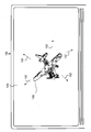
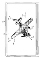
도 10 내지 도 12는 도 5 내지 도 9에 예시된 감지 영역 내의 물체들의 움직임들에 응답하여 디스플레이 상에 디스플레이되는 이미지의 파라미터의 변화를 예시하는 디스플레이의 평면도들.
도 13 내지 도 17은 본 발명의 또 다른 실시예에 따른, 감지 영역 내의 2 개의 물체들의 움직임들을 예시하는 도 2 내지 도 4의 감지 영역의 평면도들.
도 18 내지 도 20은 도 13 내지 도 17에 예시된 감지 영역 내의 물체들의 움직임들에 응답하여 디스플레이 상에 디스플레이되는 이미지의 파라미터의 변화를 예시하는 디스플레이의 평면도들.
도 21 내지 도 25는 본 발명의 다른 실시예에 따른, 감지 영역 내의 2 개의 물체들의 움직임들을 예시하는 도 2 내지 도 4의 감지 영역의 평면도들.1 is a block diagram of an exemplary system including an input device according to an embodiment of the invention.
2-4 are side views of the sensing area of the input device of FIG. 1 illustrating the presence of an object on a surface associated with the sensing area of the input device, movement of the object across the surface, and removal of the object from the surface.
5-9 are top views of the sensing area of FIGS. 2-4 illustrating the movements of two objects, in accordance with one embodiment of the present invention.
10-12 are plan views of a display illustrating a change in a parameter of an image displayed on the display in response to movements of objects in the sensing area illustrated in FIGS. 5-9.
13-17 are plan views of the sensing area of FIGS. 2-4 illustrating the movements of two objects in the sensing area, according to another embodiment of the invention.
18-20 are top views of a display illustrating a change in a parameter of an image displayed on a display in response to movements of objects in the sensing area illustrated in FIGS. 13-17.
21-25 are top views of the sensing area of FIGS. 2-4 illustrating movements of two objects in the sensing area, in accordance with another embodiment of the present invention.
다음의 상세한 설명은 사실상 단지 예시적인 것이며, 본 발명 또는 본 발명의 적용 및 용도들을 제한하도록 의도되지 않는다. 또한, 이전 기술 분야, 배경기술, 요약 또는 다음의 상세한 설명에 제공된 임의의 표시되거나 암시된 이론에 의해 경계가 구분되도록 의도되지 않는다. The following detailed description is merely illustrative in nature and is not intended to limit the invention or its applications and uses. Furthermore, no boundaries are intended to be bounded by any expressed or implied theory provided in the preceding technical field, background, summary or the following detailed description.
본 발명은 개선된 가용성을 용이하게 하는 입력 장치 및 방법을 제공한다. 상세하게, 상기 입력 장치 및 방법은 장치 상의 물체 모션 및 디스플레이 상의 결과적인 동작 간의 맵핑을 제공한다. 하나의 예로서, 상기 입력 장치 및 방법은 입력들의 다양한 조합들을 사용하여 전자 시스템의 파라미터를 사용자가 변경하도록 허용하여, 더욱 즐거운 사용자 경험 및 개선된 성능을 제공한다. The present invention provides input devices and methods that facilitate improved availability. In particular, the input device and method provide a mapping between object motion on the device and the resulting motion on the display. As one example, the input device and method allow users to change parameters of the electronic system using various combinations of inputs, providing a more enjoyable user experience and improved performance.
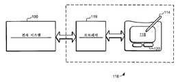
도면들로 돌아가서, 도 1은 입력 장치에 결합된 예시적인 전자 시스템(100), 또는 근접 센서 장치(116)의 블록도이다. 전자 시스템(100)은 임의의 유형의 개인용 컴퓨터, 휴대용 컴퓨터, 워크스테이션, PDA, 비디오 게임 플레이어, 통신 장치(무선 전화기 및 메시징 장치들을 포함), 기록기들 및 플레이어들(텔레비전, 케이블 박스들, 음악 플레이어들, 및 비디오 플레이어들)을 포함하는 미디어 장치, 디지털 카메라, 비디오 카메라 또는 사용자로부터 입력 수용하고 정보를 프로세싱할 수 있는 다른 장치를 대표하도록 해석된다. 따라서, 시스템(100)의 다양한 실시예들은 임의의 유형의 프로세서, 메모리 또는 디스플레이를 포함할 수 있다. 또한, 시스템(100)의 요소들은 버스, 네트워크 또는 다른 유선 또는 무선 상호 접속을 통해 통신할 수 있다. 입력 장치(116)는, 몇몇의 비제한적인 예들을 나열하기 위해 I2C, SPI, PS/2, USB(Universal Serial Bus), 블루투스, RF, IRDA, 또는 임의의 유형의 유선 또는 무선 접속을 포함하여 임의의 유형의 인터페이스 또는 접속을 통해 시스템(100)에 접속될 수 있다. Returning to the figures, FIG. 1 is a block diagram of an example
입력 장치(116)(예를 들면, 터치패드)는 프로세싱 시스템(또는 프로세서)(119) 및 감지 영역(118)을 포함한다. 입력 장치(116)는 감지 영역(118) 내의 스타일러스(114) 또는 손가락 및/또는 다른 입력 물체의 위치에 민감하다. 본원에서 사용된 "감지 영역"(118)은, 입력 장치의 센서가 물체의 위치를 검출할 수 있는 입력 장치(116) 위, 주변, 내 및/또는 근처의 임의의 공간을 널리 포함하도록 의도된다. 종래의 실시예에서, 감지 영역(118)은 센서의 표면으로부터 거리에 대해 하나 이상의 방향들로 신호 대 잡음 비가 물체 검출을 방해할 때까지 공간으로 확장된다. 이러한 거리는 밀리미터, 밀리미터들, 센티미터들 등 보다 작은 정도일 수 있고, 사용되는 위치 감지 기술의 유형 및 원하는 정확도에 따라 상당히 변동할 수 있다. 다른 실시예들은 인가된 압력 유무에 따라 표면과의 접촉을 요구할 수 있다. 따라서, 특정 감지 영역들의 평탄성, 크기, 형상 및 정확한 위치들은 실시예에 따라 크게 변동할 것이다. The input device 116 (eg, touchpad) includes a processing system (or processor) 119 and a
동작 시에, 입력 장치(116)는 프로세싱 시스템(119)을 사용하여 감지 영역(118) 내의 스타일러스(114), 손가락 또는 다른 입력 물체의 위치를 적절히 검출하고, 위치 정보의 전기 또는 전자 표시를 전자 시스템(100)에 제공한다. 시스템(100)은 사용자로부터 입력들을 수용하고, 디스플레이 상의 커서 또는 다른 물체를 움직이거나 임의의 다른 목적을 위해 표시를 적절히 프로세싱한다. In operation, the
입력 장치(116)는 하나 이상의 감지 영역들(118)을 구현하기 위해 감지 기술의 임의의 조합을 활용하는 센서(도시되지 않음)를 포함한다. 입력 장치(116)는 물체의 존재를 검출하기 위해 다양한 기술들을 사용할 수 있고, 물체의 존재를 검출하도록 구성된 하나 이상의 전극들 또는 다른 구조들을 포함할 수 있다. 몇몇의 비제한적인 예들로서, 입력 장치(116)는 용량성, 저항성, 유도성, 표면 음파, 및/또는 광학 기술들을 사용할 수 있다. 많은 이들 기술들은, 기계적 구조들이 실질적으로 긴 사용 수명을 가질 수 있기 때문에, 움직이는 기계적 구조들(예를 들면, 기계적 스위치들)을 요구하는 것에서 이롭다. 터치 센서 장치의 공통 용량성 구현에서, 감지 표면에 걸쳐 전계를 생성하기 위해 통상적으로 전압이 인가된다. 용량성 입력 장치들은, 물체로 인한 전계의 변화에 의해 야기된 커패시턴스의 변화를 검출함으로써 물체의 위치를 검출한다. 유사하게, 공통 저항성 구현에서, 가요성 상부층 및 하부층은 요소들을 절연함으로써 분리되고, 상기 층들에 걸쳐 전압 증감률이 생성된다. 가요성 상부층을 누르는 것은 상부층과 하부층 간의 전기 접촉을 생성한다. 저항성 입력 장치들은 물체의 접촉점에서 구동 전극들 간의 상대적인 저항들로 인해 전압 출력을 검출함으로써 물체의 위치를 검출한다. 유도성 구현에서, 센서는 공진 코일 또는 코일들의 쌍에 의해 유도된 루프 전류들을 픽업하고, 거리, 배향 또는 위치를 결정하기 위해 크기, 위상 및/또는 주파수의 일부 조합을 사용할 수 있다. 이들 경우들 모두에서, 입력 장치(116)는 물체의 존재를 검출하고, 검출된 물체의 표시를 전자 시스템(100)에 전달한다. 예를 들면, 입력 장치(116)의 센서는 임의의 수의 감지 영역들(118)을 지원하기 위해 용량성 센서 전극들의 어레이들을 사용할 수 있다. 또 다른 예로서, 센서는 동일한 감지 영역 또는 상이한 감지 영역들을 지원하기 위해 저항성 감지 기술과 조합하여 용량성 감지 기술을 사용할 수 있다. 본 발명의 다양한 실시예들을 구현하는데 사용될 수 있는 기술 유형들의 예들은 미국 특허 제 5,543,591 호, 미국 특허 제 6,259,234 호 및 미국 특허 제 5,815,091 호에서 알 수 있고, 이들 각각은 시냅틱스 인크에 양도되었다.
때때로 근접 센서 프로세서 및 터치 센서 제어기로서 지칭되는 프로세싱 시스템(119)은 센서 및 전자 시스템(100)에 결합된다. 일반적으로, 프로세싱 시스템(119)은 센서로부터 전기 신호들을 수신하고, 전기 신호들을 프로세싱하고, 전자 시스템(100)과 통신한다. 프로세싱 시스템(119)은 입력 장치(116)를 구현하기 위해 센서로부터 수신된 신호들에 대해 다양한 프로세스들을 수행하도록 구성된다. 예를 들면, 프로세싱 시스템(119)은 개별적인 센서 전극들을 선택 또는 접속하고, 존재/근접도를 검출하고, 위치 또는 모션 정보를 계산하고, 문턱값에 도달될 때 위치 또는 모션을 보고하고, 이를 전자 시스템(100)에 보고하거나 이를 사용자에게 표시하기 전에, 유효 탭/스트로크/문자/버튼/제스처 시퀀스를 해석 및 대기한다. 프로세싱 시스템(119)은 또한 근접한 센서에서 물체 모션들의 특정 유형들 또는 조합들이 발생할 때를 결정할 수 있다. 예를 들면, 프로세싱 시스템(119)은 물체가 센서로부터 올라갈 때 물체가 움직이는 방향을 결정할 수 있고, 이러한 모션에 응답하여 적절한 표시를 생성할 수 있다.
본 명세서에서, 용어, "프로세싱 시스템"은, 언급된 동작들을 수행하도록 구성된 하나 이상의 프로세싱 요소들을 포함하는 것으로 규정된다. 따라서, 프로세싱 시스템(119)은, 센서로부터 전기 신호들을 수신하고 전자 시스템(100)과 통신하는 하나 이상의 집적 회로들, 펌웨어 코드, 및/또는 소프트웨어 코드의 일부 또는 모두를 포함할 수 있다. 일부 실시예들에서, 프로세싱 시스템(119)을 포함하는 모든 프로세싱 요소들은 입력 장치(116) 내에 또는 근처에 함께 배치된다. 다른 실시예들에서, 이들 요소들은 물리적으로 분리될 수 있고, 프로세싱 시스템(119)의 일부 요소들은 입력 장치(116)에 가깝고, 일부는 다른 곳(가령, 전자 시스템(100)에 대한 다른 회로 근처)에 있다. 후자의 실시예에서, 입력 장치(116) 근처의 요소들에 의해 최소의 프로세싱이 수행될 수 있고, 다른 곳의 요소들에 의해 대다수의 프로세싱이 수행될 수 있다. As used herein, the term “processing system” is defined to include one or more processing elements configured to perform the operations described. Thus,
또한, 프로세싱 시스템(119)은, 그가 통신하는 전자 시스템의 부분으로부터 물리적으로 분리될 수 있거나, 프로세싱 시스템(119)은 전자 시스템의 일부와 일체로 구현될 수 있다. 예를 들면, 프로세싱 시스템(119)은, 입력 장치(116)를 구현하는 것 이외에 전자 시스템에 대한 다른 기능들을 수행하는 프로세싱 시스템 상에 적어도 부분적으로 존재할 수 있다. In addition, the
다시, 본 명세서에서 사용된 용어로서, 용어, "전자 시스템"은 광범위하게 입력 장치(116)와 통신하는 임의의 유형의 장치를 지칭한다. 따라서, 전자 시스템(100)은 터치 센서 장치가 구현되거나 결합될 수 있는 임의의 유형의 장치 또는 장치들을 포함할 수 있다. 입력 장치(116)는 전자 시스템(100)의 일부로서 구현될 수 있거나, 임의의 적절한 기술을 사용하여 전자 시스템에 결합될 수 있다. 비제한적인 예들로서, 전자 시스템(100)은 임의의 유형의 컴퓨팅 장치, 미디어 플레이어, 통신 장치 또는 다른 입력 장치(가령, 또 다른 터치 센서 장치 또는 키패드)를 포함할 수 있다. 일부 경우들에서, 전자 시스템(100)은 대형 시스템의 주변 장치 그 자체이다. 예를 들면, 전자 시스템(100)은, 적절한 유선 또는 무선 기술을 사용하여 컴퓨터 또는 미디어 시스템과 통신하는 원격 제어기 또는 디스플레이 장치(예를 들면, 텔레비전용 원격 제어기)와 같은 데이터 입력 또는 출력 장치일 수 있다. 또한, 전자 시스템(100)의 다양한 요소들(프로세서, 메모리 등)이 전체 시스템의 일부, 터치 센서 장치의 일부, 또는 그의 조합으로서 구현될 수 있다는 것을 유의하라. 또한, 전자 시스템(100)은 입력 장치(116)에 대한 호스트 또는 슬레이브일 수 있다.Again, as used herein, the term “electronic system” broadly refers to any type of device in communication with the
예시된 실시예에서, 입력 장치(116)는 버튼들(120)로 구현된다. 버튼들(120)은 부가적인 입력 기능을 입력 장치(116)에 제공하도록 구현될 수 있다. 예를 들면, 버튼들(120)은 입력 장치(116)를 사용하는 아이템들의 선택을 용이하게 하는데 사용될 수 있다. 물론, 이것은 단지 부가적인 입력 기능이 입력 장치(116)에 부가될 수 있는 방법의 하나의 예이다. 다른 구현들에서, 입력 장치(116)는 물리적 또는 가상 스위치들과 같은 대안 또는 부가적인 입력 장치들, 또는 부가적인 근접 감지 영역들을 포함할 수 있다. 역으로, 입력 장치(116)는 어떠한 부가적인 입력 장치들 없이 구현될 수 있다.In the illustrated embodiment, the
유사하게, 프로세싱 시스템(119)에 의해 제공된 위치 정보는 물체 존재의 임의의 적절한 표시일 수 있다. 예를 들면, 프로세싱 시스템(119)은 "제로-차원" 1-비트 위치 정보, 스칼라로서 "1 차원" 위치 정보(예를 들면, 감지 영역을 따라), 값들의 조합으로서 "2 차원" 또는 "3 차원" 벡터 위치 정보(예를 들면, 수평/수직/깊이 축들, 각도/방사상 축들, 또는 2 또는 3 차원들을 포괄하는 축들의 임의의 다른 조합) 등을 제공하도록 구현될 수 있다. 또한, 본원에서 사용되는 용어 "위치 정보"는 절대 및 상대적인 위치 유형 정보, 및 하나 이상의 방향들의 모션의 측정치를 포함하여 속도, 가속도 등과 같은 다른 유형들의 공간-도메인 정보를 광범위하게 포함하도록 의도된다. 또한, 다양한 형태의 위치 정보는 제스처 인식 등의 경우로서 시간 이력 성분들을 포함할 수 있다. 이하에 상세히 설명되는 바와 같이, 프로세싱 시스템(119)으로부터의 위치 정보는, 커서 제어를 위한 포인팅 장치로서 입력 장치(116)의 용도를 포함하여 인터페이스 입력들의 완전한 범위를 용이하게 한다. Similarly, the location information provided by the
일부 실시예들에서, 프로세싱 시스템(119)은 입력 장치(116)에서 다른 기능들을 수행하도록 구성될 수 있다. 예를 들면, 프로세싱 시스템(119)은 개별적인 센서 전극들을 선택 또는 접속하고, 존재/근접도를 검출하고, 위치 또는 모션 정보를 계산하고, 문턱값에 도달될 때 위치 또는 모션을 보고하고, 및/또는 이를 전자 장치(100)에 보고하거나 이를 사용자에게 표시하기 전에 유효한 탭/스트로크/문자/버튼/제스처 시퀀스를 해석 및 대기하도록 구성될 수 있다. In some embodiments,
본원에 기재된 다양한 실시예들이 "근접 센서 장치들"로서 지칭되지만, 본원에 사용된 이들 용어들이 종래의 입력 장치들뿐만 아니라 하나 이상의 손가락들, 포인터들, 스타일러스 및/또는 다른 물체의 위치를 검출할 수 있는 광범위한 동등한 입력 장치들을 포함하도록 의도된다는 것을 유의해야 된다. 그러한 장치들은, 제한 없이, 터치 스크린들, 터치 패드들, 터치 태블릿들, 생체 인증 장치들, 수기 또는 문자 인식 장치들 등을 포함할 수 있다. 다시, 본원에 사용된 용어로서, 용어 "전자 장치"는 광범위하게 입력 장치(116)와 통신하는 임의의 유형의 장치를 지칭한다. 따라서, 전자 장치(100)는 터치 센서 장치가 구현되거나 결합될 수 있는 임의의 유형의 장치 또는 장치들을 포함할 수 있다. 따라서, 근접 센서 장치들은 단지 물체의 존재 또는 부재 이상의 것을 적절히 검출할 수 있고, 광범위한 동등물들을 포함할 수 있다. While various embodiments described herein are referred to as "proximity sensor devices," these terms used herein may detect the location of one or more fingers, pointers, stylus and / or other objects, as well as conventional input devices. It should be noted that it is intended to include the widest range of equivalent input devices available. Such devices may include, without limitation, touch screens, touch pads, touch tablets, biometric devices, handwritten or text recognition devices, and the like. Again, as used herein, the term “electronic device” broadly refers to any type of device in communication with the
또한, 입력 장치(116)는 전자 시스템(100)의 일부로서 구현될 수 있거나, 임의의 적절한 기술을 사용하여 전자 시스템(100)에 결합될 수 있다. 따라서, 비제한적인 예들로서, 전자 시스템(100)은 임의의 유형의 컴퓨팅 장치, 미디어 플레이어, 통신 장치 또는 게임 장치를 포함할 수 있다. 일부 경우들에서, 전자 시스템(100)은 대형 시스템의 주변 장치 자체이다. 예를 들면, 전자 시스템(100)은, 적절한 유선 또는 무선 기술을 사용하여 컴퓨터 또는 미디어 시스템과 통신하는 원격 제어기 또는 디스플레이 장치(예를 들면, 텔레비전용 원격 제어기)와 같은 데이터 입력 또는 출력 장치일 수 있다. 또한, 전자 시스템(100)의 다양한 요소들(예를 들면, 디스플레이 스크린, 프로세서, 메모리 등)이 전체 시스템의 일부, 입력 장치의 일부, 또는 그의 조합으로서 구현될 수 있다는 것을 유의해야 된다. 또한, 전자 장치(100)는 입력 장치(116)에 대한 호스트 또는 슬레이브일 수 있다. In addition, the
본 발명의 실시예들에서, 입력 장치(116)는 사용자 인터페이스의 일부로서 입력 장치(116)를 사용하여 전자 시스템에서 용이하게 조정하도록 하는 능력을 사용자에게 제공하도록 구성된다. 예를 들면, 이것은, 스크롤링, 패닝, 메뉴 내비게이션, 커서 제어 등과 같은 사용자 인터페이스 내비게이션을 용이하게 하는데 사용될 수 있다. 또 다른 예로서, 이것은, 컬러, 색조, 밝기 및 콘트라스트와 같은 시각적 파라미터들, 볼륨, 피치, 및 강도와 같은 청각적 파라미터들, 속도 및 증폭과 같은 동작 파라미터들을 포함하는 장치 파라미터를 변경하는 것과 같은 값 조정을 용이하게 하는데 사용될 수 있다. 입력 장치(116)는 또한 기계의 움직임을 제어하는 것과 같이 기계 장치의 제어를 위해 사용될 수 있다. In embodiments of the present invention,
또한, 본 발명의 실시예들이 근접 센서 장치의 완전한 기능에 관하여 기재되지만, 본 발명의 메카니즘이 다양한 형태들의 프로그램 제품으로서 분배될 수 있다는 것이 이해될 것이다. 예를 들면, 본 발명의 메카니즘은 컴퓨터 판독 가능한 신호 포함 매체 상의 근접 센서 프로그램으로서 구현 및 분배될 수 있다. 또한, 본 발명의 실시예들은 분배를 수행하는데 사용되는 특정 유형의 컴퓨터 판독 가능한 신호 포함 매체와 상관없이 동일하게 적용한다. 신호 포함 매체의 예들은 메모리 스틱들/카드들/모듈들, 광학 및 자기 디스크, 및 하드 드라이브들과 같은 기록 가능한 매체를 포함한다. In addition, although embodiments of the present invention are described with respect to the full functionality of the proximity sensor device, it will be understood that the mechanism of the present invention may be distributed as various forms of program product. For example, the mechanism of the present invention may be implemented and distributed as a proximity sensor program on a computer readable signal bearing medium. In addition, embodiments of the present invention apply equally regardless of the particular type of computer readable signal bearing medium used to perform the distribution. Examples of signal bearing media include recordable media such as memory sticks / cards / modules, optical and magnetic disks, and hard drives.
본 발명의 적어도 일부 실시예들에서, 입력 장치 및 방법은 입력 장치 상의 손가락(또는 다른 물체) 모션과 컴퓨터 디스플레이 상의 결과적인 포인터 모션 간의 맵핑에 의해 구현된다.In at least some embodiments of the present invention, the input device and method are implemented by mapping between finger (or other object) motion on the input device and the resulting pointer motion on the computer display.
본원에 개시된 기술들은 전자 시스템(100)의 기능의 다양한 파라미터들의 조정을 용이하게 하도록 의도된다. 그러한 파라미터들의 예들은 이미지(예를 들면, 픽처 또는 텍스트)의 파라미터, 디스플레이의 설정들(가령, 밝기, 컬러, 콘트라스트 등), 및 오디오 설정들(가령, 볼륨, 밸런스, 최고 음역 레벨, 최저 음역 레벨 등)을 포함한다. 하나의 실시예에서, 파라미터는 이미지의 크기(예를 들면, 줌 레벨) 또는 이미지의 수직 또는 수평 위치(예를 들면, 스크롤링)와 같이, 디스플레이 장치에 의해 디스플레이되는 이미지에 관련된다. The techniques disclosed herein are intended to facilitate the adjustment of various parameters of the functionality of the
이러한 기술들은, 특정 파라미터의 변경, 및 변경의 연속을 개시하기 위해 감지 영역(118) 내의 물체들의 2 개 이상의 움직임들, 또는 제스처들을 조합하는 것으로 설명될 수 있다. 또한, 2 개 이상의 움직임들은 다수의 부분들을 갖는 단일의 제스처를 공동으로 형성하는 것으로 이해될 수 있다. 하나의 실시예에서, 2 개(이상) 물체들의 존재는 감지 영역(118) 내에서 검출되고, 이후에, 물체들 중 적어도 하나의 제 1 움직임은 파라미터가 변경되도록 한다. 물체들 중 적어도 하나가 감지 영역 내에 남아있고, "전이 이벤트"가 검출된 후에 제 2 움직임을 수행하면, 파라미터에서 변화가 계속된다. 감지 영역(118)에서 물체들의 제거는 변화의 중지를 야기하고, 프로세스는 2 개의 물체들을 감지 영역에 다시 놓음으로써 재개될 수 있다. 그러나, 물체들 중 하나가 감지 영역(118) 내에 남아있고, 제 3 움직임을 겪는다면, 파라미터의 변화가 "반전"될 수 있다. Such techniques may be described as combining two or more movements, or gestures, of objects in the
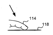
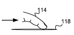
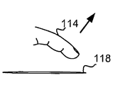
도 2 내지 도 25는 본 발명의 다양한 실시예들에 따른 상술된 시스템들 및 방법들의 동작을 예시한다. 도 2 내지 도 4는 물체가 감지 영역(118) 내에 있고, 감지 영역(118)을 가로질러 움직이고, 감지 영역(118)으로부터 제거되는 하나의 예를 예시한다. 상세하게, 도 2는 입력 물체(114)(예를 들면, 사용자의 손가락)가 감지 영역(118)에 배치(또는 이미 감지 영역 내에 위치됨)되는 것을 예시한다. 도 3은 입력 물체(114)가 감지 영역(118)을 가로질러 움직이는 것을 예시하고, 이는 상술된 움직임들 중 하나에 대응한다. 도 4는 입력 물체(114)가 감지 영역(118) 외부로 들어 올려지거나 제거되는 것을 예시한다.2-25 illustrate the operation of the systems and methods described above in accordance with various embodiments of the present invention. 2-4 illustrate one example where an object is in the
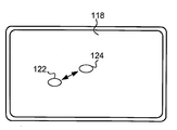
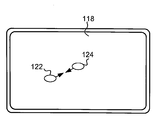
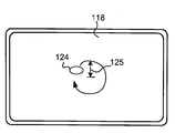
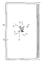
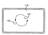
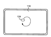
도 5 내지 도 9는 감지 영역(118) 내의 2 개의 입력 물체들(114)의 움직임 시퀀스 동안에 감지 영역(118)의 평면도들이다. 감지 영역(118) 내의 입력 물체들(114)의 팁들의 위치는 인터페이스 서클들(122 및 124)에 의해 표시되고, 이는 입력 물체들(114)과 감지 영역(118)의 인터페이스를 나타낸다. 즉, 서클들(122 및 124)은, 입력 물체들(114)이 배치되고 움직이는 감지 영역(118)의 특정 영역들(감지 영역 내의 물체들(114)의 부분들)을 표시한다. 따라서, 다음의 논의에서, 용어들 "입력 물체들" 및 "인터페이스 서클들"은 상호 변경 가능하게 사용될 수 있다. 도 7에서 서클(122)의 "점선" 모양은, 각각의 입력 물체(114)가 감지 영역(118)으로부터 제거된 감지 영역(118)의 특정 영역을 나타낸다.5-9 are plan views of the
도 10 내지 도 12는, 도 5 내지 도 9에 도시된 입력 물체들(114)의 움직임들에 응답하여 디스플레이(128) 상에 디스플레이된 예시적인 이미지(130)의 파라미터에 대해 이루어지는 조정들 및 변화들을 예시하는 입력 장치(116)(도 1)와 통신하도록 동작 가능한, 디스플레이(128)를 갖는 디스플레이 장치(126)의 평면도들이다. 이미지(130)가 물체(예를 들면, 비행기)를 나타내는 픽처로서 도시되지만, 본원에 사용된 단어, "이미지"는 물체들의 픽처들(즉, 비디오들 또는 정지 이미지들), 다양한 유형의 텍스트 및 다른 심볼들, 및/또는 도식들 및 지도들과 같이, 디스플레이 장치(126)에 의해 생성되는 임의의 시각적 디자인을 지칭하는 것으로 해석된다는 것이 이해되어야 한다. 10-12 are adjustments and changes made to the parameters of the
도 5에 도시된 바와 같이, 초기에, 감지 영역(118) 내에 2 개의 입력 물체들(114)의 동시 존재가 감지된다. 특히, 도 5는, 인터페이스 서클들(122 및 124)의 움직임이 없는 것으로 표시된 바와 같이, 입력 물체들(114)(예를 들면, 사용자의 2 개의 손가락들 또는 하나의 손가락 및 엄지손가락)이 감지 영역(118) 내에서 정지 상태인 감지 영역(118)을 예시한다.As shown in FIG. 5, initially, the simultaneous presence of two
도 6에 예시된 바와 같이, 인터페이스 서클들(122 및 124)(즉, 입력 물체들(114))은 그들의 상대적인 위치들이 변경되는(즉, 제 1 모션) 제 1 움직임을 겪는다. 본 발명의 제 1 특징에 따라, 인터페이스 서클들(122 및 124)의 위치들의 상대적인 변화를 기술하는 측정치(또는 제 1 측정치)가 아래에 기재된 바와 같이 결정 및 사용된다. 도시된 특정 예에서, 위치들의 상대적인 변화의 측정치는 서클들(122 및 124) 간의 거리 변화(예를 들면, 증가)일 수 있다. As illustrated in FIG. 6, interface circles 122 and 124 (ie, input objects 114) undergo a first movement in which their relative positions are changed (ie, a first motion). In accordance with the first aspect of the invention, a measurement (or first measurement) describing the relative change in the positions of the interface circles 122 and 124 is determined and used as described below. In the particular example shown, the measure of relative change in positions may be a change in distance (eg, an increase) between
적어도 하나의 실시예에서, 파라미터의 변화가 입력 물체들(114) 중 단지 하나의 움직임에 의해 개시될 수 있다는 것이 이해되어야 한다(예를 들면, 인터페이스 서클(122)은 정지 상태에 머무는 반면에, 인터페이스 서클(124)은 인터페이스 서클(122)로 움직인다). 파라미터의 변화의 크기는, 하나의 실시예에서, 서클들(122 및 124)의 움직임(들)을 기술하는 측정치(예를 들면, 서클들(122 및 124) 간의 거리)에 기초한다. 예를 들면, 하나의 실시예에서, 이미지(130)의 줌 레벨은 서클들(122 및 124) 간의 거리의 증가에 비례하여 증가된다.In at least one embodiment, it should be understood that the change in the parameter may be initiated by the movement of only one of the input objects 114 (eg, the
다른 실시예들에서, 인터페이스 서클들(122 및 124)의 상대적인 위치를 기술하는 측정치는 다른 다양한 유형들의 측정들을 포함할 수 있다. 예를 들면, 상기 측정치는 제 1 물체와 제 2 물체(또는 인터페이스 서클들(122 및 124))의 결정된 중심들 간의 거리를 포함할 수 있다. 또한, 측정치는 제 1 물체의 위치 및 제 2 물체의 위치에 의해 규정된 방향을 포함할 수 있다. 예를 들면, 방향은 제 1 물체에서 제 2 물체로 지시하는 벡터의 것일 수 있고, 그 역도 가능하다. 그러한 방향은 적절한 기준 프레임에 대한 각도로서 측정될 수 있다(예를 들면, 규정된 제로 각도 방향을 갖는 극 좌표 시스템 사용, 포지티브 X 축과 정렬된 방향이 제로로 간주되고, X 축으로부터 시계 반대 방향의 각도들이 포지티브로 간주되는 데카르트 좌표 시스템 등을 사용함). 부가적인 예로서, 방향은 라인과 같은 기준 및 2 개의 위치들에 의해 규정된 각도(예를 들면, 제 1 및 제 2 물체들의 결정된 중심들을 교차하는 라인 및 기준 라인 간의 각도)로서 측정될 수 있다. 기준은 또한 동적으로 이루어질 수 있고, 이전 입력 위치들, 초기 위치들 등과 같은 요인들에 기초할 수 있다. 기준은 또한, 사용자가 설정 가능하게 이루어질 수 있다. In other embodiments, the measurement describing the relative position of the interface circles 122 and 124 can include other various types of measurements. For example, the measurement may include a distance between the determined centers of the first object and the second object (or
또한, 측정치는 상대적인 위치들을 기술하는 상이한 양들의 조합을 포함할 수 있다. 예를 들면, 측정치는 물체들 간의 거리 및 물체들에 의해 규정된 방향 양자의 조합을 포함할 수 있다.In addition, the measurement may include a combination of different amounts describing the relative positions. For example, the measurement may include a combination of both the distance between the objects and the direction defined by the objects.
많은 실시예들에서, 측정치를 결정하는 단계는 물체들의 실제 위치들이 계산되거나 실제 중심들이 결정되는 것을 요구하지 않는다는 것을 또한 유의해야 된다. 예를 들면, 물체들에 의해 규정된 방향 및/또는 물체들 간의 거리는 각각의 물체의 위치를 명시적으로 계산하지 않고 결정될 수 있다. 일부 실시예들은 제 1 및 제 물체들에 대한 가능한 위치들의 세트 중에서 임의의 선택들을 효과적으로 사용한다. 이러한 실시예들에서, 제 1 및 제 2 물체들의 잠재적인 위치들의 상이한 세트들이 존재하고, 잠재적인 위치들이 제 1 및 제 2 물체들의 실제 위치들일지라도, 측정에 대한 값은 이들 잠재적인 위치들의 세트들 중 하나 이상으로부터 결정된다. 특정 예는 직교 축들을 따라 정렬된 센서 전극들의 세트들을 포함하는 센서 어레이를 갖는 용량성 프로파일형 센서 장치를 사용한다. 그러한 용량성 프로파일형 센서는 입력 물체들에 대한 센서 전극들 각각의 총 용량성 결합을 효과적으로 측정하여, 감지 영역(118) 내의 임의의 수의 물체들의 2차원(2D) 위치들을 기술하도록 2 개의 단일 축들 프로파일들이 생성된다. 따라서, 제 1 입력 물체 및 제 2 입력 물체가 센서 전극들 근처에 배치되면, 제 1 및 제 2 물체들의 잠재적인 위치들이 물체들의 실제 위치들을 반영하는 프로파일들로부터 애매할 수 있다. 그러나, 잠재적인 위치들 간의 거리가 양자의 세트들에서 동일하다. 따라서, 측정치로서 거리를 사용하는 것은 실제 위치들이 결정될 필요가 없다는 것을 의미한다.It should also be noted that in many embodiments, determining the measurement does not require the actual positions of the objects to be calculated or the actual centers to be determined. For example, the direction defined by the objects and / or the distance between the objects can be determined without explicitly calculating the position of each object. Some embodiments effectively use any choices among the set of possible positions for the first and first objects. In such embodiments, even though there are different sets of potential positions of the first and second objects, and the potential positions are actual positions of the first and second objects, the value for the measurement is the set of these potential positions. Is determined from one or more of these. A particular example uses a capacitive profiled sensor device having a sensor array comprising sets of sensor electrodes aligned along orthogonal axes. Such a capacitive profiled sensor effectively measures the total capacitive coupling of each of the sensor electrodes to the input objects, thereby describing two single (2D) positions of any number of objects within the
또한, 제 1 및 제 2 물체들의 상대적인 위치들은, 물체들이 기준의 또 다른 프레임에 대해 움직일지라도 (물체들이 서로에 대해 실질적으로 정지 상태이도록) 실질적으로 동일하게 머무를 수 있다. 예를 들면, 제 1 및 제 2 물체들이 동일한 속도로 감지 영역(118)을 통해 움직인다면, 제 1 및 제 2 물체들은 그들이 감지 영역(118)에 대해 모션이 있을지라도 서로에 대해 모션이 없을 것이다. In addition, the relative positions of the first and second objects may stay substantially the same (so that the objects are substantially stationary relative to each other) even though the objects move relative to another frame of reference. For example, if the first and second objects move through the
이러한 경우들 중 임의의 경우에, 도 10 및 도 11에 도시된 바와 같이, 결정된 측정치(상대적인 위치 및/또는 각도)는 파라미터에 대해 제 1 조정을 하는데 사용될 수 있다. 도시된 실시예에서, 변경된 이미지(130)의 특정 파라미터는, 일반적으로 이해되는 바와 같이, 이미지(130)의 크기, 또는 "줌" 레벨이다. 도 10에 도시된 이미지(130)의 예시적인 크기는 도 5에 도시된 바와 같은 서클들(122 및 124)의 위치들에 대응한다. 인터페이스 서클들(122 및 124)이 멀리 움직임에 따라(도 6), 도 11에 표시된 바와 같이, 이미지(130)는 줌 화살표들(132)(사용자에게 보이지 않을 수 있음)로 표시된 바와 같이 크기가 증가된다(또는 "줌 인"). 하나의 실시예에서, 파라미터의 변화는, 서클들(122 및 124)이 검출된 움직임(들)이 파라미터의 원하는 변화를 나타낸다고 결정된 후까지(예를 들면, 서클들(122 및 124) 간의 거리의 초기 문턱값을 넘을 때까지) 개시되지 않는다. In any of these cases, as shown in FIGS. 10 and 11, the determined measurement (relative position and / or angle) can be used to make a first adjustment to the parameter. In the illustrated embodiment, the particular parameter of the modified
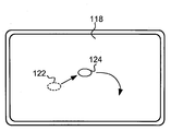
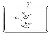
도 7을 참조하여, "전이" 이벤트 또는 모드 스위칭 이벤트는 제 1 움직임 후에 검출된다. 도 7에 도시된 예시적인 전이 이벤트는, 서클(124)이 계속해서 움직이는 동안(즉, 제 2 모션), 감지 영역(118)으로부터 서클(122)에 대응하는 입력 물체(114)의 제거이다. 즉, 입력 물체들(114) 중 하나는 감지 영역으로부터 제거되고, 다른 입력 물체는 감지 영역에 남아있다. 도시된 예에서, 인터페이스 서클(124)은 전이 이벤트 후에 아치형 경로를 따라 움직인다. Referring to FIG. 7, a "transition" event or a mode switching event is detected after the first movement. The exemplary transition event shown in FIG. 7 is the removal of the
전이 이벤트로서 사용될 수 있는 물체들(114)에 의한 동작들의 다른 예들은 문턱값(하이 또는 로우)을 넘는 2 개의 물체 간의 거리 및/또는 각도(또는 거리 및/또는 각도의 변화), 및 문턱값(하이 또는 로우)을 넘는 물체들(114) 중 하나의 움직임의 곡률 반경을 포함하고, 예를 들면, 물체들 중 하나가 미리 결정된 시간의 양 동안 "휠링(whirling)" 방식(상대적으로 작은 곡률 반경을 가짐)으로 움직인다. Other examples of operations by
도 8을 참조하여, 인터페이스 서클(124)은, 예를 들면, 도 7에서 개시된 아치형 경로를 따라 계속해서 움직이고, 따라서, 동일한 방향으로 계속해서 선회할 수 있다. 상술된 것과 유사한 방식에서, 전이 이벤트 후에 감지 영역(118) 내의 입력 물체들(114)(예를 들면, 인터페이스 서클(124)) 중 하나의 움직임을 기술하는 측정치가 결정되고, 또한 파라미터를 조정하는데 사용된다. 인터페이스 서클(124)의 모션은 임의의 경로 형상을 포함할 수 있고, 조정에 대한 측정치는 경로 길이에 기초할 수 있다. 파라미터는 인터페이스 서클들(122 및 124)의 각도 변화에 의해 결정되는 것과 동일한 방식으로 계속해서 조정될 수 있다. 이와 같이, 도 12를 참조하여, 도시된 실시예에서, 이미지의 크기는 계속해서 증가한다. 하나의 실시예에서, 입력 물체들(114)의 하나 또는 양자가 전이 이벤트의 시작 및 전이 이벤트 후에 입력 물체(들)(114)의 모션의 시작 사이에 감지 영역(118) 내에 계속해서 남아있다면, 파라미터의 연속 변화가 발생한다. With reference to FIG. 8, the
하나의 실시예에서, 파라미터의 연속 변화의 크기는, 전이 이벤트가 검출된 후에 서클(124)의 움직임을 기술하는 측정치(예를 들면, 경로 길이)에 기초한다. 하나의 실시예에서, 측정치는 경로 길이 측정치(물체가 움직인 경로의 총 길이의 측정치)를 포함할 수 있다. 경로 길이 계산의 예들은 서클(124)의 움직임의 필터링되거나 이상화된 추정으로부터 유도된 측정, 및 서클(124)이 움직이는 경로를 근사화한 선형 세그먼트들의 합을 포함한다. 다른 실시예들에서, 대안적인 측정들은 하나 이상의 축들(가령, 데카르트 좌표 시스템에서 X 또는 Y 축)을 따른 변위, 및 이동된 경로의 선택 축들을 따른 변위들의 비율들(ratios)을 포함할 수 있다. 파라미터의 변화는, 인터페이스 서클(124)이 도 7에서 개시된 아치형 경로를 따라(즉, 동일한 지배적인 선회 방향에서) 계속해서 움직이는 한 계속될 것이다. 또 다른 실시예에서, 파라미터의 변화는, 인터페이스 서클(124)이 센서 영역 내에 남아있는 한 계속될 것이다. 전이 이벤트가 물체들(114) 중 하나가 휠링 모션으로 움직이는 것인 실시예에서, 파라미터의 변화가 계속되도록 하는 서클(124)의 움직임은, 원형 모션의 움직임을 포함하는 "라운드 스크롤링"일 수 있지만, 곡률 반경은 휠링 모션보다 더 크다. In one embodiment, the magnitude of the continuous change in the parameter is based on a measure (eg, path length) that describes the movement of the
하나의 실시예에서, 측정치는 경로 길이 측정치(물체가 이동한 경로의 총 길이의 측정치)를 포함할 수 있다. 대안적인 실시예들에서, 측정들은 하나 이상의 축들(가령, 데카르트 좌표 시스템에서 X 또는 Y 축)을 따른 변위, 및 이동된 경로의 선택 축들을 따른 변위들의 비율들, 서클(124)의 필터링되거나 이상화된 추정으로부터 유도된 측정치, 및 서클(124)이 이동한 경로의 세그먼트들의 합을 포함할 수 있다. In one embodiment, the measurement may comprise a path length measurement (a measurement of the total length of the path the object traveled). In alternative embodiments, the measurements may include the displacement of one or more axes (eg, the X or Y axis in a Cartesian coordinate system), and the ratios of displacements along the selected axes of the traveled path, filtered or idealized of the
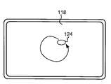
하나의 실시예에서, 물체들(114) 중 하나가 제거된 후에, 서클(124)이 아치형 경로를 따라 계속해서 움직이고, 이미지(130)는 도 12에 도시된 바와 같이 크기가 계속해서 증가한다. 일부 실시예들에서, 파라미터 연속 변화는, 양자의 물체들(114)이 도 6 및 도 7에 도시된 모션들 사이에서 감지 영역 내에 남아있는 경우에 발생할 것이다. 그러한 실시예에서, 제 2 제스처 또는 모션은 서클들(122 및 124) 양자 중 하나의 아치형 모션인 것으로 간주될 수 있다. 또 다른 실시예에서, 물체들(114) 중 하나가 제거된 후에, 서클(124)은 직선 세그먼트와 같은 선형 경로, 직사각형과 같은 다각형의 윤곽을 그릴 수 있는 다중 선형 경로들, 물결 라인 세그먼트, 부분적인 호와 같은 비선형 경로, 또는 하나 이상의 원형 경로들, 및 임의의 수의 경로들로 움직일 수 있다. 예를 들면, 경로는 한번 이상 그 자신과 교차될 수 있다. In one embodiment, after one of the
도 8에 도시된 바와 같이, 서클(124)이 계속해서 선회함에 따라, 경로는 각각의 입력 물체(114)가 "휠링" 모션(즉, 일련의 루프들 또는 서클들)을 겪는 것으로 표시될 수 있다. 도 12의 이미지(130)는, 도시된 휠링 모션이 동일한 방향(예를 들면, 시계 방향)으로 계속되는 한 크기가 계속해서 증가될 수 있다. As shown in FIG. 8, as the
도 9를 참조하여, 인터페이스 서클(124)의 모션은 또한 파라미터가 반전되도록 조정되어 "반전"되도록 하여(예를 들면, 크기 감소 또는 "줌 아웃"), 인터페이스 서클은, 예를 들면, 도 11 및 도 10에 도시된 그의 크기로 각각 복귀된다. 하나의 실시예에서, 파라미터의 반전 또는 반대, 변화의 크기는 감지 영역(118)에 걸쳐 또는 감지 영역(118)에 대한 물체들(114) 중 하나(예를 들면, 감지 영역 내에 남아있는 물체)의 경로 길이와 같이, 반전된 모션을 기술하는 결정된 측정치에 기초할 수 있다. 반전된 방향은 "선명한 반전" 또는 각도 방향의 변화로서 기술될 수 있다. 선명한 반전은 초기 경로에 대해 동일한 경로 또는 예각을 갖는 경로를 따라 반대 방향의 모션을 포함할 수 있다.With reference to FIG. 9, the motion of the
파라미터 변화의 반전을 일으키는 모션은 또한 "극성"에 대해 규정될 수 있다. 특정 방향(예를 들면, 시계 방향)으로의 충분한 선회가 발생할 때, 초기 극성은 선회 방향과 연관된다. 극성은 갑자기 방향을 반전시키거나(상술된 바와 같이), 극성이 선회 방향과 연관된 후에, 극성 연관 방향으로부터 반대 방향(예를 들면, 시계 반대 방향)으로 충분히 선회함으로써 반전될 수 있다.The motion causing the inversion of the parameter change can also be defined for "polarity". When sufficient turn in a particular direction (eg clockwise) occurs, the initial polarity is associated with the turn direction. The polarity can be reversed by suddenly inverting the direction (as described above), or by sufficiently turning in the opposite direction (eg counterclockwise) after the polarity is associated with the turning direction.
2 개의 가장 흔한 제어 제스처들이 선형 또는 회전 모션들일 수 있고, 선형 모션들이 작은 익스커션들(excursions)에 대해 자연스럽고 원형 모션들이 더 큰 움직임들에 대해 자연스럽기 때문에, 양자를 처리하는 통합된 메카니즘이 요구된다는 것이 이해되어야 한다. 차원 감소를 위한 이들 2 개의 유형의 모션의 통합은 주로 적절한 부호 관리의 기능이다. 단일 방향의 연속된 선형 움직임은 반전을 일으킬 수 없다. 그러나, 선형 움직임 동안의 방향의 분명한 반전은 반전을 일으킬 수 있다. 또한, 특정 대칭성(handedness)의 계속된 선회 움직임은 반전을 일으킬 수 없다. 그러나, 회전 모션의 대칭성에서 분명한 반전은 반전을 일으킬 수 있다. Since the two most common control gestures can be linear or rotational motions, linear motions are natural for small excursions and circular motions are natural for larger motions, an integrated mechanism that processes both is required. It should be understood. The integration of these two types of motion for dimension reduction is mainly a function of proper code management. Continuous linear movement in a single direction cannot cause inversion. However, a clear inversion of direction during linear movement can cause inversion. In addition, continued swinging movements of a certain handedness cannot cause inversion. However, a clear inversion in the symmetry of the rotational motion can cause inversion.
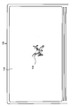
남아있는 입력 물체(114)가 감지 영역(118)에서 제거되면, 파라미터의 변화가 중지되고, 프로세스가 사용자에 의해 재개될 수 있다. 하나의 실시예에서, 입력 물체(들)(114)가 미리 결정된 시간 동안(예를 들면, 프로세스가 사용자에 의해 재개되기 전에) 감지 영역(118) 외부에 머물게 되면, 파라미터의 변화가 중지될 수 있다. 인터페이스 서클(124)의 움직임이 정지되지만, 입력 물체(114)가 감지 영역(118) 내에 남아있다면, 파라미터의 변화가 중지된다. 그러나, 사용자는 도 7 및 도 8에 표시된 방식으로 물체(114)를 다시 움직이게 함으로써 변화를 재개할 수 있다. 하나의 실시예에서, 입력 물체(114)가 감지 영역(118) 내에 남아있고, 반대 선회 방향으로 아치형 경로를 따라 움직이기 시작하면(도 9), 파라미터의 변화가 반전되어, 이미지(130)의 크기가 감소된다(또는 "줌 아웃"). 예를 들면, 이미지(130)는 도 11 및 도 10에 도시된 크기들로 각각 복귀될 수 있다. When the remaining
대안적인 실시예에서, 입력 물체(114)가 감지 영역(118) 내에 남아있고, 반대 선회 방향으로 아치형 경로를 따라 움직이기 시작하면(도 9), 파라미터의 변화가 계속되어, 이미지(130)의 크기가 증가된다(또는 "줌 인"). 다른 실시예에서, 사용자는 입력 물체(114)를 감지 영역(118) 내에 남겨두고, 직선 세그먼트와 같은 선형 경로, 직사각형과 같은 다각형의 윤곽을 그릴 수 있는 다수의 선형 경로들, 물결 라인 세그먼트, 부분적인 호와 같은 비선형 경로, 또는 하나 이상의 원형 경로들, 및 임의의 수의 경로들을 포함하여 경로들의 임의의 조합으로 입력 물체(114)를 움직임으로써 동일한 방식으로 파라미터에 대해 조정을 계속할 수 있다. 예를 들면, 경로는 한번 이상 자신과 교차할 수 있다. 파라미터의 이러한 "반대 변화"의 크기는 상술된 움직임들과 유사하게 인터페이스(124)의 움직임의 경로 길이에 기초할 수 있다. In an alternative embodiment, once the
파라미터의 초기 변화와 유사한 방식에서, 파라미터의 반대 변화는 또한, 남아있는 입력 물체(114)를 감지 영역(118)으로부터 제거하거나 인터페이스 서클(124)의 움직임을 중지시킴으로써 중지될 수 있다. 이와 같이, 하나의 실시예에서, 사용자는 입력 물체(114)를 감지 영역(118) 내에 남겨두고, 반대 방향들로 입력 물체(114)를 휠링함으로써 반대 방식들로 파라미터를 반복적으로 변경할 수 있다. 적어도 하나의 실시예에서, 파라미터의 변화가 발생하는 속도(또는 레이트)는 인터페이스 서클들(122 및 124)이 움직이는 속도에 의존한다. 즉, 인터페이스 서클들(122 및 124)의 속도가 증가함에 따라, 파라미터가 변화되는 레이트가 증가한다. In a manner similar to the initial change in the parameter, the opposite change in the parameter can also be stopped by removing the remaining
도 13 내지 도 20은 또 다른 동작 모드 또는 또 다른 실시예에 따른 입력 장치(116) 및 디스플레이 장치(126)의 동작을 예시한다. 특히, 도 13 내지 도 17은 도 5 내지 도 9에 도시된 것과 유사한 인터페이스 서클들(122 및 124)의 움직임을 예시한다. 그러나, 도 13 및 도 14에 표시된 바와 같이, 2 개의 입력 물체들(114)의 초기 움직임은 인터페이스 서클들(122 및 124) 간의 거리가 감소되도록 한다. 이전과 같이, 이러한 모션이 실질적으로 선형으로 도시되지만, 도 14에 도시된 움직이는 서클들(122)(및/또는 124)의 경로들은, 예를 들면, 실질적으로 무한 곡률 반경을 갖는 아치형 경로인 것으로 이해될 수 있다. 도 18 내지 도 20은 도 13 내지 도 17에 도시된 인터페이스 서클들(122 및 124)의 움직임들에 응답하여 이미지(130)의 동일한 파라미터(예를 들면, 크기)에 대해 조정들 및 변화들이 이루어지는 디스플레이 장치(126)를 예시한다. 13 through 20 illustrate the operation of the
상술된 실시예에서와 같이, 초기에, 감지 영역(118) 내의 2 개의 입력 물체들(114)의 동시 존재가 도 13에 도시된 바와 같이 감지된다. 도 18에 도시된 이미지(130)의 예시적인 크기는 도 13에 도시된 바와 같은 서클들(122 및 124)의 위치들에 대응할 수 있다. As in the embodiment described above, initially, the simultaneous presence of two
도 14를 참조하여, 도시된 실시예에서, 인터페이스 서클(122 및 124)은 제 1 움직임을 겪어, 그들 사이의 거리가 감소된다. 서클들(122 및 124) 간의 거리의 이러한 감소는 파라미터의 변화가 기초하는 측정치(상술된 바와 같음)로서 사용될 수 있다. 서클들(122 및 124) 간의 각도의 변화가 또한 상술된 바와 같이 측정치로서 사용될 수 있다는 것을 유의해야 된다. 도 14에 도시된 모션의 결과로서, 적절한 파라미터가 조정되고, 도시된 실시예에서, 이는 도 19의 줌 화살표(132)로 표시된 바와 같이 이미지(130)의 크기 감소(또는 "줌 아웃")이다.Referring to FIG. 14, in the illustrated embodiment, the interface circles 122 and 124 undergo a first movement, so that the distance between them is reduced. This reduction in the distance between the
도 15를 참조하여, 시스템이 조정 모드로 진입하도록 하는 전이 이벤트가 검출된다. 도시된 바와 같이, 도시된 전이 이벤트는 감지 영역(118)으로부터 입력 물체들(114) 중 하나의 제거를 포함한다. 물체들(114) 중 하나가 제거된 후에(즉, 전이 이벤트), 조정 모드에 진입되고, 서클(124)은 제 2 경로(도 15)를 따라 계속해서 움직이고, 이미지(130)는 도 20에 도시된 바와 같이 크기가 계속해서 감소한다. 이전과 같이, 파라미터의 이러한 변화의 크기들은 서클들(122 및 124)의 상대적인 위치들 또는 움직임들(예를 들면, 감지 영역(118)에 대한 물체(들)(114)의 모션의 경로 길이)을 기술하는 측정치에 기초할 수 있다. 프로세스는 상술된 것과 유사한 방식으로 중지될 수 있고, 마찬가지로, 파라미터의 변화는 감지 영역(118) 내에 남아있는 입력 물체(114)의 연속적인 존재 및 반대 방향으로 지배적인 선회 방향을 갖는 제 2 경로를 따른 인터페이스 서클(124)의 모션에 의해 계속될 수 있다. Referring to FIG. 15, a transition event is detected that causes the system to enter a mode of adjustment. As shown, the transition event shown includes the removal of one of the input objects 114 from the
조정 모드에 진입한 후에, 파라미터는 2 개의 물체들(114)의 초기 움직임에 의해 규정된 것과 동일한 방식으로 계속해서 조정될 수 있고(예를 들면, "줌 아웃"), 반면에 남아있는 입력 물체(114)(즉, 대응하는 인터페이스 서클(124))는 도 15에 도시된 바와 같이 제 2 경로를 따라 계속해서 움직인다. 제 2 경로는 상술된 것과 유사한 경로들의 임의의 조합을 포함할 수 있다. 도 16에 도시된 바와 같이, 인터페이스 서클(124)은 제 2 경로를 따라 계속해서 움직일 수 있다. 도 15 및 도 16에 도시된 모션들은 곡률 반경(123)을 갖는 경로들을 따를 수 있고, 이는 도 14에 도시된 경로의 곡률 반경(예를 들면, 무한)보다 더 작다. After entering the adjustment mode, the parameter can be continuously adjusted in the same way as defined by the initial movement of the two objects 114 (eg, "zoom out"), while the remaining input object ( 114 (ie, the corresponding interface circle 124) continues to move along the second path as shown in FIG. 15. The second route may comprise any combination of routes similar to those described above. As shown in FIG. 16, the
하나의 실시예에서, 남아있는 입력 물체(114)의 움직임이 반전될지라도, 파라미터는 초기 움직임에 의해 규정된 방식으로 계속해서 조정될 수 있다(예를 들면, "줌 아웃"). 따라서, 도 17에 도시된 바와 같이, 인터페이스 서클(124)이 도 9에 도시된 것과 유사한 방식으로 선회 모션의 방향을 반전시킬 때, 이미지(130)의 크기가 계속해서 감소될 수 있다. 인터페이스 서클(124)의 반전된 모션은 도 17에 도시된 바와 같이 제 3 아치형 경로를 따를 수 있고, 제 3 아치형 경로는 도 14에 도시된 경로(들)의 곡률 반경보다 작고, 제 2 경로의 곡률 반경(132)(도 15 및/또는 도 16)보다 더 크거나 작은 곡률 반경(125)을 가질 수 있다. In one embodiment, even if the movement of the remaining
도 21 내지 도 25는, 예를 들면, 도 10 내지 도 12 및/또는 도 18 내지 도 20에 도시된 것과 유사한 이미지에 변화들을 실시하는데 사용될 수 있는 인터페이스 서클들(122 및 124)의 움직임들을 예시한다. 도 21에 도시된 바와 같이, 입력 물체들(114)은 감지 영역(118) 내에서 동시에 감지되어, 인터페이스 서클들(122 및 124)이 정지 상태이다. 도 22를 참조하여, 인터페이스 서클들(122 및 124) 중 하나 또는 양자는 제 1 아치형 경로(예를 들면, 제 1 지배적인 선회 방향으로)를 따라 움직여서, 그의 상대적인 위치들을 기술하는 각도가 변한다. 도시된 실시예에서, 인터페이스 서클들(122 및 124) 간의 거리는 실질적으로 일정하게 된다. 21-25 illustrate movements of
하나의 실시예에서, 인터페이스 서클들(122 및 124)의 초기 움직임은 특정 파라미터에 대한 임의의 조정을 일으키지 않는다. 오히려, 상대적인 위치들을 기술하는 각도(또는 각도의 변화)가 문턱값을 넘을 때, 시스템은 명시적인 전이 이벤트를 검출하지 않고(문턱값을 넘는 것이 전이 이벤트로 고려될 수 있지만) 조정 모드에서 "고정"된다. 조정 모드에 진입한 후에, 파라미터(예를 들면, 이미지(130)의 크기)는 감지 영역(118)에 대한 입력 물체들(114) 중 하나 또는 양자를 기술하는 측정치(예를 들면, 입력 물체(들)(114) 간의 경로 길이 또는 각도의 변화 및 감지 영역(118) 내의 참조 포인트)에 기초하여 조정된다.In one embodiment, the initial movement of the interface circles 122 and 124 does not cause any adjustment to the particular parameter. Rather, when an angle (or change in angle) describing relative positions exceeds a threshold, the system does not detect an explicit transition event (though exceeding the threshold may be considered a transition event) in fixed mode in a fixed mode. "do. After entering the adjustment mode, the parameter (e.g., the size of the image 130) is measured to describe one or both of the input objects 114 for the sensing area 118 (e.g. (S) and the change in path length or angle between the
모드의 잠금이 활용되어, 파라미터가 조정(예를 들면, "증가" 또는 "감소")되는 방식은 인터페이스 서클들(122 및 124)의 초기 움직임에 의해 결정될 수 있다. 예를 들면, 도 22에 도시된 인터페이스 서클들의 시계 반대 방향 모션은 이미지(130)를 줌 아웃하는데 사용될 수 있거나 이미지(130)의 크기를 감소시키는데 사용될 수 있다. 이미지(130)의 크기 감소는, 모션이 임의의 방법으로 "반전"될지라도 모드 잠금 후에 입력 물체(들)(114)의 모션의 방향 또는 형상과 상관없이 계속될 수 있다. 이와 같이, 인터페이스 서클(124)은 도 23에서 아치형 경로를 따라 움직이지 않지만, 이미지(130)는 크기가 계속해서 감소할 수 있다. 또한, 도 24 및 도 25에 도시된 명백한 반전 모션들은 또한 이미지(130)가 동일한 방법으로 조정되도록 할 수 있다(예를 들면, 줌 아웃). Locking of the mode is utilized so that the way the parameter is adjusted (eg, "increase" or "decrease") may be determined by the initial movement of the interface circles 122 and 124. For example, the counterclockwise motion of the interface circles shown in FIG. 22 may be used to zoom out of the
상술된 것과 유사한 방식에서, 조정 모드 및 모드 잠금은 감지 영역(118)으로부터 남아있는 입력 물체(들)를 (즉, 미리 결정된 시간 동안) 제거함으로써 비활성화될 수 있다. 하나의 실시예에서, 입력 물체(들)(114)가 미리 결정된 시간 동안 감지 영역(118) 외부에 있다면(예를 들면, 프로세스가 사용자에 의해 재개되기 전에), 모드 잠금은 비활성화될 수 있다. 사용자는 입력 물체들(114) 양자를 감지 영역(118)에 위치시킴으로써 프로세스를 재개할 수 있다. In a manner similar to that described above, the adjustment mode and mode lock can be deactivated by removing the remaining input object (s) from the sensing area 118 (ie, for a predetermined time). In one embodiment, the mode lock may be deactivated if the input object (s) 114 are outside the
하나의 실시예에서, 물체들(114) 중 하나가 움직이는 경로의 "키랄리티(chirality)"는, 파라미터의 변화가 계속되는지 및/또는 변화가 역전될 때(예를 들면, 물체(114)의 선회 모션이 반전될 때)를 결정하는데 사용될 수 있다. 키랄 경로(chiral path)는 2 차원 공간을 통한 이산 경로(discrete path)이고, 상기 경로를 따른 각각의 세그먼트는 2 개의 가능한 키랄리티들 중 하나로 라벨링된다. 세그먼트의 키랄리티는 지배적이거나 "바람직한" 선회 방향에 의해 지정된다. 본원에서 사용하기 위해 유기 화학으로부터 용어를 적응시켜, 좌선성(levorotary)(L) 세그먼트는 일반적으로 왼손 선회 시퀀스의 일부이다. 우선성(dextrorotary)(D) 세그먼트는 일반적으로 우측으로 크게 선회하는 것이다. 예를 들면, 원형 경로가 시계 반대 방향(CCW)으로 횡단되면, 그의 세그먼트들은 L이고, 또는 시계 방향으로 횡단하면, 세그먼트들은 D이다. In one embodiment, the “chirality” of the path in which one of the
키랄 경로의 세그먼트들이 라벨링되면, 이는 경로를 일차원 출력 변수로 맵핑하기 쉽다. 키랄리티는 출력의 부호를 확립하는 역할을 하고, 횡단된 거리는 크기를 확립하는 역할을 한다. 다른 실시예들이 반대 및/또는 임의의 다른 방식을 사용할 수 있지만, 관례의 의해, L 세그먼트들은 포지티브 출력들을 생성하고, D 경로들은 네가티브 출력들을 생성한다. 입력 경로 길이로부터 출력 크기를 유도하는 것은 2 차원 포인팅 장치의 완전한 동적 범위가 임의의 연관된 1 차원 임무를 포함하도록 허용한다. 이러한 1 차원 출력 변수는, 파라미터가 변경되는 방식(예를 들면, 이미지(130)의 크기 증가 또는 감소)을 결정하는데 사용될 수 있다. Once the segments of the chiral path are labeled, it is easy to map the path to a one-dimensional output variable. The chirality serves to establish the sign of the output, and the traversed distance serves to establish the magnitude. While other embodiments may use the reverse and / or any other way, by convention, the L segments produce positive outputs, and the D paths produce negative outputs. Deriving the output size from the input path length allows the full dynamic range of the two dimensional pointing device to include any associated one dimensional task. This one-dimensional output variable can be used to determine how the parameter is changed (eg, increasing or decreasing the size of the image 130).
또 다른 실시예에서, 물체들(114) 중 하나가 움직이는 입력 경로의 각도는, 파라미터의 변화가 계속되는지 및/또는 변화가 반전될 때(예를 들면, 물체(114)의 선회 모션이 반전될 때)를 결정하는데 사용될 수 있다. 입력 경로의 각도는 경로를 따라 제 1 변위 벡터 및 제 1 변위 벡터를 바로 뒤따르는 제 2 변위 벡터에 의해 규정될 수 있다. 제 1 변위 벡터는 제 1 위치에서 제 2 위치로의 변위를 나타내고, 제 2 변위 벡터는 제 2 위치에서 제 3 위치로의 변위를 나타낸다. 입력 경로의 각도는 제 1 및 제 2 변위 벡터들 간의 각도이고, 상기 각도는 파라미터가 변경되는 방식을 결정한다(예를 들면, 이미지(130)의 크기 증가 또는 감소). 각도가 기준값보다 크면, 이것은 계속되는 것으로 간주되고, 각도가 기준값보다 작다면, 이것은 계속되는 것으로 간주되지 않는다. In another embodiment, the angle of the input path through which one of the
본원에 설명된 실시예들 및 예들은, 본 발명 및 그의 특정 애플리케이션을 최상으로 설명하고, 이로써 당업자가 본 발명을 제조 및 사용하도록 하기 위해 제공되었다. 그러나, 상기 설명 및 예들이 단지 예시 및 예를 위해 제공된다는 것을 당업자는 인식할 것이다. 설명된 기재는 완전한 것으로 의도되지 않고 본 발명을 개시된 정밀한 형태로 제한하도록 의도되지 않는다. 다음의 청구항의 정신으로부터 벗어나지 않고 상기 사상을 고려하여 많은 수정들 및 변동들이 가능하다. The embodiments and examples described herein are provided to best describe the present invention and its specific application, thereby enabling those skilled in the art to make and use the present invention. However, those skilled in the art will recognize that the above description and examples are provided for the purposes of illustration and example only. The described description is not intended to be exhaustive or to limit the invention to the precise forms disclosed. Many modifications and variations are possible in light of the above teachings without departing from the spirit of the following claims.
100: 전자 시스템 114: 입력 물체
116: 입력 장치 118: 감지 영역
119: 프로세싱 시스템 120: 버튼
122, 124: 인터페이스 서클 123: 곡률 반경
126: 디스플레이 장치 128: 디스플레이
130: 이미지 132: 줌 화살표100: electronic system 114: input object
116: input device 118: detection area
119: processing system 120: button
122, 124: interface circle 123: radius of curvature
126: display device 128: display
130: Image 132: Zoom Arrow
Claims (26)
감지 영역 내의 제 2 물체에 대한 제 1 물체의 위치 변화를 검출하는 단계로서, 상기 제 1 물체 및 상기 제 2 물체는 상기 감지 영역 내에 동시에 존재하는, 상기 위치 변화 검출 단계;
상기 감지 영역 내의 상기 제 2 물체에 대한 상기 제 1 물체의 상기 위치 변화를 기술하는 제 1 측정치를 결정하는 단계;
상기 감지 영역 내의 상기 제 2 물체에 대한 상기 제 1 물체의 상기 위치 변화에 응답하여 상기 파라미터에 대해 제 1 조정을 표시하는 단계로서, 상기 파라미터에 대한 상기 제 1 조정의 크기는 상기 제 1 측정치에 기초하는, 상기 제 1 조정 표시 단계;
상기 감지 영역 내의 상기 제 2 물체에 대한 상기 제 1 물체의 상기 위치 변화를 검출한 후에, 상기 감지 영역 내의 상기 제 1 물체의 모션을 검출하는 단계;
상기 감지 영역에 대한 상기 제 1 물체에 대한 상기 모션을 기술하는 제 2 측정치를 결정하는 단계; 및
상기 감지 영역 내의 상기 제 2 물체에 대한 상기 제 1 물체의 상기 위치 변화의 시작 및 상기 감지 영역 내의 상기 제 1 물체의 상기 모션의 시작 사이에, 상기 제 1 물체의 상기 모션 및 상기 감지 영역 내의 상기 제 1 및 제 2 물체들 중 적어도 하나의 연속적인 존재를 검출하는 것에 응답하여 상기 파라미터에 대한 제 2 조정을 표시하는 단계로서, 상기 파라미터에 대한 상기 제 2 조정의 크기는 상기 제 2 측정치에 기초하는, 상기 제 2 조정 표시 단계를 포함하는, 파라미터의 조정 실시 방법.In the method of adjusting the parameters:
Detecting a change in the position of the first object relative to a second object in the sensing area, wherein the first object and the second object are simultaneously present in the sensing area;
Determining a first measurement describing the change in position of the first object relative to the second object within the sensing area;
Indicating a first adjustment to the parameter in response to the change in position of the first object relative to the second object in the sensing area, wherein the magnitude of the first adjustment to the parameter is dependent on the first measurement. Based, said first adjustment display step;
After detecting the change in position of the first object relative to the second object in the sensing area, detecting the motion of the first object in the sensing area;
Determining a second measurement describing the motion relative to the first object relative to the sensing area; And
Between the start of the position change of the first object with respect to the second object in the sensing area and the start of the motion of the first object in the sensing area, the motion of the first object and the within the sensing area. Indicating a second adjustment to the parameter in response to detecting a continuous presence of at least one of the first and second objects, wherein the magnitude of the second adjustment to the parameter is based on the second measurement And a second adjustment display step.
상기 감지 영역 내의 상기 제 2 물체에 대한 상기 제 1 물체의 상기 위치 변화 및 상기 감지 영역 내의 상기 제 1 물체의 상기 모션 간의 전이(transition)를 표시하는 전이 이벤트를 검출하는 단계를 더 포함하고, 상기 제 2 조정 표시 단계는 또한 상기 전이 이벤트를 검출하는 것에 응답하여 발생하는, 파라미터의 조정 실시 방법.The method of claim 1,
Detecting a transition event indicative of a transition between the change in position of the first object relative to the second object in the sensing area and the motion of the first object in the sensing area; And the second adjustment indication step also occurs in response to detecting the transition event.
상기 전이 이벤트는 상기 감지 영역으로부터 상기 제 1 및 제 2 물체들 중 적어도 하나의 제거를 포함하는, 파라미터의 조정 실시 방법.The method of claim 2,
And wherein the transition event comprises removing at least one of the first and second objects from the sensing area.
상기 전이 이벤트는 상기 제 1 측정치가 문턱값을 넘는 것을 포함하는, 파라미터의 조정 실시 방법.The method of claim 2,
And wherein the transition event comprises the first measurement exceeding a threshold.
상기 감지 영역 내의 상기 제 2 물체에 대한 상기 제 1 물체의 상기 위치 변화를 기술하는 제 1 측정치를 결정하는 단계는,
상기 제 2 물체에 대한 상기 제 1 물체의 상기 위치 변화를 기술하는 거리 변화를 결정하는 단계를 포함하는, 파라미터의 조정 실시 방법.The method of claim 1,
Determining a first measurement describing the change in position of the first object relative to the second object in the sensing area,
Determining a change in distance describing the change in position of the first object relative to the second object.
상기 감지 영역 내의 상기 제 2 물체에 대한 상기 제 1 물체의 상기 위치 변화를 기술하는 제 1 측정치를 결정하는 단계는,
상기 제 2 물체에 대한 상기 제 1 물체의 상기 위치 변화를 기술하는 각도 변화를 결정하는 단계를 포함하는, 파라미터의 조정 실시 방법.The method of claim 1,
Determining a first measurement describing the change in position of the first object relative to the second object in the sensing area,
Determining an angle change describing the change in position of the first object relative to the second object.
상기 감지 영역 내의 상기 제 1 물체의 상기 모션을 검출한 후에, 상기 감지 영역 내의 상기 제 1 물체의 제 2 모션을 검출하는 단계로서, 상기 제 2 모션은 상기 제 1 모션의 반대인, 상기 제 2 모션 검출 단계;
상기 감지 영역에 대한 상기 제 1 물체의 상기 제 2 모션을 기술하는 제 3 측정치를 결정하는 단계; 및
상기 제 1 물체의 상기 제 2 모션을 검출하는 것에 응답하여 상기 파라미터에 대한 제 3 조정을 표시하는 단계로서, 상기 파라미터에 대한 상기 제 3 조정은 상기 제 3 측정치에 기초하고, 상기 파라미터에 대한 상기 제 3 조정은 상기 파라미터에 대한 상기 제 2 조정의 반대가 아닌, 상기 제 3 조정 표시 단계를 더 포함하는, 파라미터의 조정 실시 방법.The method of claim 1,
After detecting the motion of the first object in the sensing area, detecting the second motion of the first object in the sensing area, wherein the second motion is opposite of the first motion. Motion detection step;
Determining a third measurement describing the second motion of the first object relative to the sensing area; And
Indicating a third adjustment to the parameter in response to detecting the second motion of the first object, wherein the third adjustment to the parameter is based on the third measurement, and And the third adjustment further comprises the third adjustment indication step, not opposite of the second adjustment to the parameter.
상기 감지 영역 내의 상기 제 1 물체의 상기 모션을 검출한 후에, 상기 감지 영역 내의 상기 제 1 물체의 제 2 모션을 검출하는 단계로서, 상기 제 2 모션은 상기 제 1 모션에 반대인, 상기 제 2 모션 검출 단계;
상기 감지 영역에 대한 상기 제 1 물체의 상기 제 2 모션을 기술하는 제 3 측정치를 결정하는 단계; 및
상기 제 1 물체의 상기 제 2 모션을 검출하는 것에 응답하여 상기 파라미터에 대한 제 3 조정을 표시하는 단계로서, 상기 파라미터에 대한 상기 제 3 조정은 상기 제 3 측정치에 기초하고, 상기 파라미터에 대한 상기 제 3 조정은 상기 파라미터에 대한 상기 제 2 조정에 반대인, 상기 제 3 조정 표시 단계를 더 포함하는, 파라미터의 조정 실시 방법.The method of claim 1,
After detecting the motion of the first object in the sensing area, detecting the second motion of the first object in the sensing area, wherein the second motion is opposite to the first motion. Motion detection step;
Determining a third measurement describing the second motion of the first object relative to the sensing area; And
Indicating a third adjustment to the parameter in response to detecting the second motion of the first object, wherein the third adjustment to the parameter is based on the third measurement, and And the third adjustment further comprises the third adjustment indication step, as opposed to the second adjustment to the parameter.
상기 제 2 측정치는 상기 감지 영역에 대한 상기 제 1 물체의 상기 모션의 경로 길이인, 파라미터의 조정 실시 방법.The method of claim 1,
And the second measurement is the path length of the motion of the first object relative to the sensing area.
상기 감지 영역 내의 제 2 물체에 대한 제 1 물체의 위치를 기술하는 각도 변화를 검출하는 단계로서, 상기 제 1 물체 및 상기 제 2 물체는 상기 감지 영역 내에 동시에 존재하는, 상기 각도 변화 검출 단계;
상기 각도 변화를 검출한 후에, 상기 파라미터의 조정을 실시하기 위한 조정 모드에 진입하는 단계;
상기 각도 변화를 검출한 후에, 상기 감지 영역 내의 상기 제 1 물체의 모션을 검출하는 단계;
상기 감지 영역에 대한 상기 제 1 물체의 상기 모션을 기술하는 측정치를 결정하는 단계; 및
상기 감지 영역 내의 상기 제 1 물체의 상기 모션을 검출하는 것에 응답하여 상기 조정 모드에 진입한 후에, 상기 파라미터에 대한 조정을 표시하는 단계로서, 상기 파라미터에 대한 상기 조정의 크기는 상기 측정치에 기초하는, 상기 조정 표시 단계를 포함하는, 파라미터의 조정 실시 방법.In a method for adjusting a parameter using a sensor device having a sensing area:
Detecting an angle change describing a position of a first object relative to a second object in the sensing area, wherein the first object and the second object are simultaneously present in the sensing area;
After detecting the angle change, entering an adjustment mode to effect adjustment of the parameter;
After detecting the angle change, detecting a motion of the first object in the sensing area;
Determining a measurement describing the motion of the first object relative to the sensing area; And
After entering the adjustment mode in response to detecting the motion of the first object in the sensing area, indicating an adjustment to the parameter, wherein the magnitude of the adjustment to the parameter is based on the measurement. And adjusting the parameter.
상기 제 2 물체에 대한 상기 제 1 물체의 위치를 기술하는 상기 각도 변화를 기술하는 제 2 측정치를 결정하는 단계, 및
상기 감지 영역 내의 상기 제 1 물체의 상기 모션을 검출하는 것에 응답하여 상기 파라미터에 대한 상기 조정을 표시하기 전에, 이전 조정을 표시하는 단계로서, 상기 이전 조정은 상기 제 2 물체에 대한 상기 제 1 물체의 위치를 기술하는 상기 각도 변화에 응답하고, 상기 이전 조정의 크기는 상기 제 2 측정치에 기초하는, 상기 이전 조정 표시 단계를 더 포함하는, 파라미터의 조정 실시 방법.The method of claim 10,
Determining a second measurement describing the angular change describing the position of the first object relative to the second object, and
Prior to displaying the adjustment to the parameter in response to detecting the motion of the first object in the sensing area, displaying a previous adjustment, wherein the previous adjustment is to the first object relative to the second object. And in response to said change of angle describing the position of said previous adjustment, said magnitude of said previous adjustment being based on said second measurement.
상기 조정 모드 진입 단계는,
상기 각도 변화가 문턱값을 넘는 것에 응답하여, 상기 조정 모드에 진입하는 단계를 포함하는, 파라미터의 조정 실시 방법.The method of claim 10,
Entering the adjustment mode,
In response to the change in angle exceeding a threshold, entering the adjustment mode.
감지 영역 내의 제 1 물체 및 제 2 물체의 존재 및 모션을 검출하도록 구성된 감지 시스템;
상기 감지 시스템에 결합된 프로세싱 시스템을 포함하고,
상기 프로세싱 시스템은:
상기 감지 영역 내의 상기 제 2 물체에 대한 상기 제 1 물체의 위치 변화를 기술하는 제 1 측정치를 결정하고;
상기 감지 영역 내의 상기 제 2 물체에 대한 상기 제 1 물체의 상기 위치 변화에 응답하여 파라미터에 대한 제 1 조정을 표시하고;
상기 감지 영역에 대한 상기 제 1 물체의 모션을 기술하는 제 2 측정치를 결정하고;
상기 감지 영역 내의 상기 제 2 물체에 대한 상기 제 1 물체의 상기 위치 변화의 시작 및 상기 감지 영역 내의 상기 제 1 물체의 상기 모션의 시작 사이에, 상기 제 1 물체의 상기 모션 및 상기 감지 영역 내의 상기 제 1 및 제 2 물체들 중 적어도 하나의 연속적인 존재에 응답하여 상기 파라미터에 대한 제 2 조정을 표시하도록 구성되고,
상기 파라미터에 대한 상기 제 1 조정의 크기는 상기 제 1 측정치에 기초하고,
상기 제 1 물체의 상기 모션은, 상기 감지 영역 내의 상기 제 2 물체에 대한 상기 제 1 물체의 상기 위치 변화 후에 발생하고,
상기 파라미터에 대한 상기 제 2 조정의 크기는 상기 제 2 측정치에 기초하는, 입력 장치.In the input device:
A sensing system configured to detect the presence and motion of a first object and a second object in the sensing area;
A processing system coupled to the sensing system,
The processing system is:
Determine a first measurement describing a change in position of the first object relative to the second object in the sensing area;
Indicate a first adjustment to a parameter in response to the change in position of the first object relative to the second object in the sensing area;
Determine a second measurement that describes the motion of the first object relative to the sensing area;
Between the start of the position change of the first object with respect to the second object in the sensing area and the start of the motion of the first object in the sensing area, the motion of the first object and the within the sensing area. And indicate a second adjustment to the parameter in response to a continuous presence of at least one of the first and second objects,
The magnitude of the first adjustment to the parameter is based on the first measurement,
The motion of the first object occurs after the change of position of the first object relative to the second object in the sensing area,
And the magnitude of the second adjustment to the parameter is based on the second measurement.
상기 프로세싱 시스템은 상기 감지 영역 내의 상기 제 2 물체에 대한 상기 제 1 물체의 상기 위치 변화 및 상기 감지 영역 내의 상기 제 1 물체의 상기 모션 간의 전이를 표시하는 전이 이벤트를 검출하도록 또한 구성되고, 상기 프로세싱 시스템은 상기 전이 이벤트에 응답하여 상기 제 2 조정을 표시하도록 또한 구성되는, 입력 장치.The method of claim 13,
The processing system is further configured to detect a transition event indicating a transition between the change in position of the first object relative to the second object in the sensing area and the motion of the first object in the sensing area, and the processing And the system is further configured to indicate the second adjustment in response to the transition event.
상기 전이 이벤트는 상기 감지 영역으로부터 상기 제 1 및 제 2 물체들 중 적어도 하나의 제거를 포함하는, 입력 장치.The method of claim 14,
The transition event comprises removing at least one of the first and second objects from the sensing area.
상기 감지 영역 내의 상기 제 2 물체에 대한 상기 제 1 물체의 상기 위치 변화를 기술하는 상기 제 1 측정치는 거리 변화를 포함하는, 입력 장치.The method of claim 13,
And the first measurement describing the change in position of the first object relative to the second object in the sensing area comprises a change in distance.
상기 감지 영역 내의 상기 제 2 물체에 대한 상기 제 1 물체의 상기 위치 변화를 기술하는 상기 제 1 측정치는 각도 변화를 포함하는, 입력 장치.The method of claim 13,
The first measurement describing the change in position of the first object relative to the second object in the sensing area comprises an angle change.
상기 파라미터에 대한 상기 제 1 및 제 2 조정들 각각은 디스플레이 상에 디스플레이되는 이미지에 대한 줌 기능, 디스플레이 상에 디스플레이되는 이미지에 대한 회전 기능, 또는 그의 조합을 포함하는, 입력 장치.The method of claim 13,
Each of the first and second adjustments to the parameter includes a zoom function for the image displayed on the display, a rotation function for the image displayed on the display, or a combination thereof.
감지 영역 내의 제 1 물체 및 제 2 물체의 존재 및 모션을 검출하도록 구성된 감지 시스템;
상기 감지 시스템에 결합된 프로세싱 시스템을 포함하고,
상기 프로세싱 시스템은:
상기 감지 영역 내의 제 2 물체에 대한 제 1 물체의 위치를 기술하는 각도 변화를 검출하고;
상기 각도 변화를 검출한 후에, 상기 파라미터에 대한 조정을 실시하기 위한 조정 모드에 진입하고;
상기 각도 변화를 검출한 후에, 상기 감지 영역 내의 상기 제 1 물체의 모션을 검출하고;
상기 감지 영역에 대한 상기 제 1 물체의 상기 모션을 기술하는 측정치를 결정하고;
상기 감지 영역 내의 상기 제 1 물체의 상기 모션을 검출하는 것에 응답하여 상기 파라미터에 대한 조정을 표시하도록 구성되고,
상기 제 1 물체 및 상기 제 2 물체는 상기 감지 영역 내에 동시에 존재하고,
상기 파라미터에 대한 상기 조정의 크기는 상기 측정치에 기초하는, 입력 장치.In the input device:
A sensing system configured to detect the presence and motion of a first object and a second object in the sensing area;
A processing system coupled to the sensing system,
The processing system is:
Detect an angle change describing a position of a first object relative to a second object within the sensing area;
After detecting the angular change, enter an adjustment mode to effect adjustment to the parameter;
After detecting the change of angle, detecting motion of the first object in the sensing area;
Determine a measurement describing the motion of the first object relative to the sensing area;
And display an adjustment to the parameter in response to detecting the motion of the first object in the sensing area,
The first object and the second object are simultaneously present in the sensing area,
The magnitude of the adjustment to the parameter is based on the measurement.
상기 파라미터에 대한 상기 조정은 나중 조정(later adjustment)이고, 상기 파라미터에 대한 이른 조정(earlier adjustment)은 상기 각도 변화를 검출하는 것에 응답하여 표시되는, 입력 장치.The method of claim 19,
The adjustment to the parameter is a later adjustment, and an early adjustment to the parameter is indicated in response to detecting the angular change.
상기 프로세싱 시스템은,
상기 제 2 물체에 대한 상기 제 1 물체의 위치를 기술하는 각도 변화를 기술하는 제 2 측정치를 결정하고,
상기 감지 영역 내의 상기 제 1 물체의 상기 모션을 검출하는 것에 응답하여, 상기 파라미터에 대한 상기 조정을 표시하기 전에, 이전 조정을 표시하도록 또한 구성되고,
상기 이전 조정은 상기 제 2 물체에 대한 상기 제 1 물체의 위치를 기술하는 상기 각도 변화에 응답하고, 상기 이전 조정의 크기는 상기 제 2 측정치에 기초하는, 입력 장치.The method of claim 19,
The processing system comprising:
Determine a second measurement describing an angular change describing the position of the first object relative to the second object,
And in response to detecting the motion of the first object in the sensing area, before displaying the adjustment to the parameter, display a previous adjustment,
The previous adjustment is responsive to the angle change describing the position of the first object relative to the second object, and the magnitude of the previous adjustment is based on the second measurement.
상기 프로세싱 시스템은 상기 각도 변화에 응답하여 상기 조정 모드에 진입하도록 또한 구성되는, 입력 장치.The method of claim 19,
And the processing system is further configured to enter the adjustment mode in response to the angle change.
입력 장치 프로그램으로서,
감지 영역 내의 제 2 물체에 대한 제 1 물체의 위치 변화를 검출하고;
상기 감지 영역 내의 상기 제 2 물체에 대한 상기 제 1 물체의 상기 위치 변화를 기술하는 제 1 측정치를 결정하고;
상기 감지 영역 내의 상기 제 2 물체에 대한 상기 제 1 물체의 상기 위치 변화에 응답하여 파라미터에 대한 제 1 조정을 표시하고;
상기 감지 영역 내의 상기 제 2 물체에 대한 상기 제 1 물체의 상기 위치 변화 후에, 전이 이벤트를 검출하고;
상기 전이 이벤트 후에, 상기 감지 영역 내의 상기 제 1 물체의 모션을 검출하고;
상기 감지 영역에 대한 상기 제 1 물체의 상기 모션을 기술하는 제 2 측정치를 결정하고;
상기 전이 이벤트의 시작 및 상기 감지 영역 내의 상기 제 1 물체의 상기 모션의 시작 사이에, 상기 제 1 물체의 상기 모션 및 상기 감지 영역 내의 상기 제 1 및 제 2 물체들 중 적어도 하나의 연속적인 존재에 응답하여 상기 파라미터에 대한 제 2 조정을 표시하도록 구성되고,
상기 제 1 물체 및 상기 제 2 물체는 상기 감지 영역 내에 동시에 존재하고,
상기 파라미터에 대한 상기 제 1 조정의 크기는 상기 제 1 측정치에 기초하고,
상기 파라미터에 대한 상기 제 2 조정의 크기는 상기 제 2 측정치에 기초하는, 상기 입력 장치 프로그램; 및
상기 입력 장치 프로그램을 포함하는 컴퓨터-판독 가능한 매체를 포함하는, 프로그램 제품.In the program product:
As an input device program,
Detect a change in the position of the first object relative to the second object in the sensing area;
Determine a first measurement describing the change in position of the first object relative to the second object in the sensing area;
Indicate a first adjustment to a parameter in response to the change in position of the first object relative to the second object in the sensing area;
After the position change of the first object with respect to the second object in the sensing area, detect a transition event;
After the transition event, detect motion of the first object in the sensing area;
Determine a second measurement describing the motion of the first object relative to the sensing area;
Between the start of the transition event and the start of the motion of the first object in the sensing area, the continuous presence of at least one of the motion of the first object and the first and second objects in the sensing area. In response to indicate a second adjustment to the parameter,
The first object and the second object are simultaneously present in the sensing area,
The magnitude of the first adjustment to the parameter is based on the first measurement,
The input device program, wherein the magnitude of the second adjustment to the parameter is based on the second measurement; And
And a computer-readable medium containing the input device program.
상기 전이 이벤트는 상기 감지 영역으로부터 상기 제 1 및 제 2 물체들 중 적어도 하나의 제거를 포함하는, 프로그램 제품.The method of claim 23,
The transition event comprises removing at least one of the first and second objects from the sensing area.
상기 전이 이벤트는 상기 제 1 측정치가 문턱값을 넘는 것을 포함하고, 상기 제 1 측정치는 상기 감지 영역 내의 상기 제 2 물체에 대한 상기 제 1 물체의 위치를 기술하는 각도 변화 및 상기 제 1 및 제 2 물체들을 분리하는 거리 중 적어도 하나를 포함하는, 프로그램 제품.The method of claim 23,
The transition event includes the first measurement exceeding a threshold, the first measurement including an angle change describing the position of the first object relative to the second object within the sensing area and the first and second And at least one of the distances separating the objects.
상기 프로세싱 시스템은,
상기 감지 영역에 대한 상기 제 1 물체의 제 2 모션을 기술하는 제 3 측정치를 결정하고,
상기 감지 영역 내의 상기 제 1 물체의 상기 모션의 시작 및 상기 감지 영역 내의 상기 제 1 물체의 상기 제 2 모션의 시작 사이에, 상기 제 1 물체의 상기 제 2 모션 및 상기 감지 영역 내의 상기 제 1 및 제 2 물체들 중 적어도 하나의 연속적인 존재에 응답하여 상기 파라미터에 대한 제 3 조정을 표시하도록 또한 구성되고,
상기 파라미터에 대한 상기 제 3 조정은 상기 제 3 측정치에 기초하는, 프로그램 제품.The method of claim 23,
The processing system comprising:
Determine a third measurement describing the second motion of the first object relative to the sensing area,
Between the start of the motion of the first object in the sensing area and the start of the second motion of the first object in the sensing area, the first motion in the sensing area and the second motion of the first object; And indicate a third adjustment to the parameter in response to a continuous presence of at least one of the second objects,
And the third adjustment to the parameter is based on the third measurement.
Applications Claiming Priority (4)
| Application Number | Priority Date | Filing Date | Title |
|---|---|---|---|
| US10724508P | 2008-10-21 | 2008-10-21 | |
| US61/107,245 | 2008-10-21 | ||
| US12/391,011 US8174504B2 (en) | 2008-10-21 | 2009-02-23 | Input device and method for adjusting a parameter of an electronic system |
| US12/391,011 | 2009-02-23 |
Publications (1)
| Publication Number | Publication Date |
|---|---|
| KR20110074600A true KR20110074600A (en) | 2011-06-30 |
Family
ID=42108277
Family Applications (1)
| Application Number | Title | Priority Date | Filing Date |
|---|---|---|---|
| KR1020117011341A KR20110074600A (en) | 2008-10-21 | 2009-10-06 | Input device and method for adjusting a parameter of an electronic system |
Country Status (6)
| Country | Link |
|---|---|
| US (1) | US8174504B2 (en) |
| EP (1) | EP2356548A2 (en) |
| JP (1) | JP5561682B2 (en) |
| KR (1) | KR20110074600A (en) |
| CN (1) | CN102257468B (en) |
| WO (1) | WO2010047945A2 (en) |
Families Citing this family (40)
| Publication number | Priority date | Publication date | Assignee | Title |
|---|---|---|---|---|
| US20100321319A1 (en) * | 2009-06-17 | 2010-12-23 | Hefti Thierry | Method for displaying and updating a view of a graphical scene in response to commands via a touch-sensitive device |
| US20110205169A1 (en) * | 2010-02-24 | 2011-08-25 | Primax Electronics Ltd. | Multi-touch input apparatus and its interface method using hybrid resolution based touch data |
| US8878773B1 (en) | 2010-05-24 | 2014-11-04 | Amazon Technologies, Inc. | Determining relative motion as input |
| JP2015038642A (en) | 2010-06-09 | 2015-02-26 | 株式会社東芝 | Display processing apparatus and display processing method |
| FR2963970B1 (en) * | 2010-08-17 | 2013-07-12 | Compagnie Ind Et Financiere Dingenierie Ingenico | METHOD OF CONTROLLING ACTIONS USING A TOUCH SCREEN |
| US20120054670A1 (en) * | 2010-08-27 | 2012-03-01 | Nokia Corporation | Apparatus and method for scrolling displayed information |
| US20120161791A1 (en) * | 2010-12-28 | 2012-06-28 | Synaptics Incorporated | Methods and apparatus for determining input objects associated with proximity events |
| US8497838B2 (en) * | 2011-02-16 | 2013-07-30 | Microsoft Corporation | Push actuation of interface controls |
| CN102692995A (en) * | 2011-03-21 | 2012-09-26 | 国基电子(上海)有限公司 | Electronic device with proximity sensing function and proximity sensing control method |
| CN103765364A (en) * | 2011-06-21 | 2014-04-30 | 统一有限责任两合公司 | Methods and products for influencing the representation of pictorial information by a display device of an information technology apparatus |
| US9041734B2 (en) | 2011-07-12 | 2015-05-26 | Amazon Technologies, Inc. | Simulating three-dimensional features |
| US10088924B1 (en) | 2011-08-04 | 2018-10-02 | Amazon Technologies, Inc. | Overcoming motion effects in gesture recognition |
| US8947351B1 (en) * | 2011-09-27 | 2015-02-03 | Amazon Technologies, Inc. | Point of view determinations for finger tracking |
| DE102011084802A1 (en) * | 2011-10-19 | 2013-04-25 | Siemens Aktiengesellschaft | Display and operating device |
| JP5160680B1 (en) * | 2011-10-26 | 2013-03-13 | 株式会社コナミデジタルエンタテインメント | Image processing apparatus, image processing apparatus control method, and program |
| JP5060651B2 (en) * | 2011-12-20 | 2012-10-31 | 株式会社東芝 | Display processing apparatus, display control program, and display processing method |
| US8942434B1 (en) | 2011-12-20 | 2015-01-27 | Amazon Technologies, Inc. | Conflict resolution for pupil detection |
| TWI547858B (en) * | 2011-12-30 | 2016-09-01 | 富智康(香港)有限公司 | System and method for controlling document scaling and rotation on a touch screen |
| US9223415B1 (en) | 2012-01-17 | 2015-12-29 | Amazon Technologies, Inc. | Managing resource usage for task performance |
| US9342195B2 (en) * | 2012-03-12 | 2016-05-17 | Microchip Technology Incorporated | System and method to share electrodes between capacitive touch controller and gesture detection device |
| US20130257792A1 (en) * | 2012-04-02 | 2013-10-03 | Synaptics Incorporated | Systems and methods for determining user input using position information and force sensing |
| US9317113B1 (en) | 2012-05-31 | 2016-04-19 | Amazon Technologies, Inc. | Gaze assisted object recognition |
| JP5846053B2 (en) * | 2012-06-14 | 2016-01-20 | ヤマハ株式会社 | Parameter control program and parameter control apparatus |
| CN103593119B (en) * | 2012-08-14 | 2017-06-13 | 国基电子(上海)有限公司 | The method that portable electron device and its display content are amplified |
| US9195368B2 (en) | 2012-09-13 | 2015-11-24 | Google Inc. | Providing radial menus with touchscreens |
| US9507425B2 (en) * | 2013-03-06 | 2016-11-29 | Sony Corporation | Apparatus and method for operating a user interface of a device |
| DE102013009009B4 (en) * | 2013-05-17 | 2023-08-03 | Elektrobit Automotive Gmbh | System and method for data selection using a touch-sensitive surface |
| US9269012B2 (en) | 2013-08-22 | 2016-02-23 | Amazon Technologies, Inc. | Multi-tracker object tracking |
| US20160196042A1 (en) * | 2013-09-17 | 2016-07-07 | Koninklijke Philips N.V. | Gesture enabled simultaneous selection of range and value |
| US10055013B2 (en) | 2013-09-17 | 2018-08-21 | Amazon Technologies, Inc. | Dynamic object tracking for user interfaces |
| JP5767303B2 (en) * | 2013-11-25 | 2015-08-19 | 利仁 曽根 | Resize request determination method |
| CN103995653B (en) * | 2014-06-09 | 2018-10-12 | 联想(北京)有限公司 | A kind of method and apparatus of parameter regulation |
| JP5984887B2 (en) * | 2014-08-25 | 2016-09-06 | キヤノン株式会社 | Zoom control device and control method thereof |
| BR112017002615A2 (en) * | 2014-09-03 | 2017-12-05 | Quaero Ltd | a human machine interface device for aircraft |
| CN105137938A (en) * | 2015-08-31 | 2015-12-09 | 中国烟草总公司广东省公司 | Intelligent tobacco field monitoring management system based on Internet of Things technology |
| US9652069B1 (en) | 2015-10-22 | 2017-05-16 | Synaptics Incorporated | Press hard and move gesture |
| US10089000B2 (en) | 2016-06-03 | 2018-10-02 | Microsoft Technology Licensing, Llc | Auto targeting assistance for input devices |
| US10459544B2 (en) * | 2017-05-19 | 2019-10-29 | Htc Corporation | Electronic system and proximity sensing method |
| US11094135B1 (en) * | 2021-03-05 | 2021-08-17 | Flyreel, Inc. | Automated measurement of interior spaces through guided modeling of dimensions |
| US20230289244A1 (en) * | 2022-01-21 | 2023-09-14 | Hewlett-Packard Development Company, L.P. | Peripheral device positions |
Family Cites Families (31)
| Publication number | Priority date | Publication date | Assignee | Title |
|---|---|---|---|---|
| US5327161A (en) | 1989-08-09 | 1994-07-05 | Microtouch Systems, Inc. | System and method for emulating a mouse input device with a touchpad input device |
| US5543591A (en) | 1992-06-08 | 1996-08-06 | Synaptics, Incorporated | Object position detector with edge motion feature and gesture recognition |
| US5880411A (en) | 1992-06-08 | 1999-03-09 | Synaptics, Incorporated | Object position detector with edge motion feature and gesture recognition |
| US5543590A (en) | 1992-06-08 | 1996-08-06 | Synaptics, Incorporated | Object position detector with edge motion feature |
| US5889236A (en) | 1992-06-08 | 1999-03-30 | Synaptics Incorporated | Pressure sensitive scrollbar feature |
| US5825352A (en) | 1996-01-04 | 1998-10-20 | Logitech, Inc. | Multiple fingers contact sensing method for emulating mouse buttons and mouse operations on a touch sensor pad |
| US5943052A (en) | 1997-08-12 | 1999-08-24 | Synaptics, Incorporated | Method and apparatus for scroll bar control |
| US8479122B2 (en) * | 2004-07-30 | 2013-07-02 | Apple Inc. | Gestures for touch sensitive input devices |
| US9292111B2 (en) | 1998-01-26 | 2016-03-22 | Apple Inc. | Gesturing with a multipoint sensing device |
| US7663607B2 (en) | 2004-05-06 | 2010-02-16 | Apple Inc. | Multipoint touchscreen |
| US7469381B2 (en) | 2007-01-07 | 2008-12-23 | Apple Inc. | List scrolling and document translation, scaling, and rotation on a touch-screen display |
| JP2001134382A (en) | 1999-11-04 | 2001-05-18 | Sony Corp | Graphic processor |
| JP4803883B2 (en) | 2000-01-31 | 2011-10-26 | キヤノン株式会社 | Position information processing apparatus and method and program thereof. |
| US7138983B2 (en) | 2000-01-31 | 2006-11-21 | Canon Kabushiki Kaisha | Method and apparatus for detecting and interpreting path of designated position |
| JP4223664B2 (en) | 2000-09-14 | 2009-02-12 | 株式会社リコー | Touch panel type coordinate input device |
| US7030861B1 (en) | 2001-02-10 | 2006-04-18 | Wayne Carl Westerman | System and method for packing multi-touch gestures onto a hand |
| JP5259898B2 (en) | 2001-04-13 | 2013-08-07 | 富士通テン株式会社 | Display device and display processing method |
| US7038659B2 (en) | 2002-04-06 | 2006-05-02 | Janusz Wiktor Rajkowski | Symbol encoding apparatus and method |
| EP1658551A1 (en) * | 2003-08-29 | 2006-05-24 | Nokia Corporation | Method and device for recognizing a dual point user input on a touch based user input device |
| EP1745456A2 (en) | 2004-04-23 | 2007-01-24 | Cirque Corporation | An improved method for scrolling and edge motion on a touchpad |
| JP4903371B2 (en) | 2004-07-29 | 2012-03-28 | 任天堂株式会社 | Game device and game program using touch panel |
| US20070046643A1 (en) | 2004-08-06 | 2007-03-01 | Hillis W Daniel | State-Based Approach to Gesture Identification |
| US7728821B2 (en) | 2004-08-06 | 2010-06-01 | Touchtable, Inc. | Touch detecting interactive display |
| US20070130547A1 (en) | 2005-12-01 | 2007-06-07 | Navisense, Llc | Method and system for touchless user interface control |
| US9395905B2 (en) | 2006-04-05 | 2016-07-19 | Synaptics Incorporated | Graphical scroll wheel |
| US20070262951A1 (en) | 2006-05-09 | 2007-11-15 | Synaptics Incorporated | Proximity sensor device and method with improved indication of adjustment |
| CN101490643B (en) | 2006-06-16 | 2011-12-28 | 塞奎公司 | A method of scrolling that is activated by touchdown in a predefined location on a touchpad that recognizes gestures for controlling scrolling functions |
| US8086971B2 (en) | 2006-06-28 | 2011-12-27 | Nokia Corporation | Apparatus, methods and computer program products providing finger-based and hand-based gesture commands for portable electronic device applications |
| DE202007018940U1 (en) * | 2006-08-15 | 2009-12-10 | N-Trig Ltd. | Motion detection for a digitizer |
| JP2008217767A (en) * | 2008-01-29 | 2008-09-18 | Fujitsu Ten Ltd | Display device |
| US20090207140A1 (en) * | 2008-02-19 | 2009-08-20 | Sony Ericsson Mobile Communications Ab | Identifying and responding to multiple time-overlapping touches on a touch panel |
-
2009
- 2009-02-23 US US12/391,011 patent/US8174504B2/en active Active
- 2009-10-06 JP JP2011532147A patent/JP5561682B2/en active Active
- 2009-10-06 WO PCT/US2009/059685 patent/WO2010047945A2/en active Application Filing
- 2009-10-06 CN CN2009801528290A patent/CN102257468B/en active Active
- 2009-10-06 KR KR1020117011341A patent/KR20110074600A/en not_active Application Discontinuation
- 2009-10-06 EP EP09793320A patent/EP2356548A2/en not_active Withdrawn
Also Published As
| Publication number | Publication date |
|---|---|
| CN102257468B (en) | 2013-11-13 |
| WO2010047945A2 (en) | 2010-04-29 |
| US20100097332A1 (en) | 2010-04-22 |
| EP2356548A2 (en) | 2011-08-17 |
| CN102257468A (en) | 2011-11-23 |
| WO2010047945A3 (en) | 2010-09-30 |
| US8174504B2 (en) | 2012-05-08 |
| JP2012506574A (en) | 2012-03-15 |
| JP5561682B2 (en) | 2014-07-30 |
Similar Documents
| Publication | Publication Date | Title |
|---|---|---|
| US8174504B2 (en) | Input device and method for adjusting a parameter of an electronic system | |
| US7884807B2 (en) | Proximity sensor and method for indicating a display orientation change | |
| US8692767B2 (en) | Input device and method for virtual trackball operation | |
| US7825797B2 (en) | Proximity sensor device and method with adjustment selection tabs | |
| US20090289902A1 (en) | Proximity sensor device and method with subregion based swipethrough data entry | |
| US20070262951A1 (en) | Proximity sensor device and method with improved indication of adjustment | |
| US8446373B2 (en) | Method and apparatus for extended adjustment based on relative positioning of multiple objects contemporaneously in a sensing region | |
| US9442650B2 (en) | Systems and methods for dynamically modulating a user interface parameter using an input device | |
| TWI599922B (en) | Electronic device with a user interface that has more than two degrees of freedom, the user interface comprising a touch-sensitive surface and contact-free detection means | |
| US20110109577A1 (en) | Method and apparatus with proximity touch detection | |
| US8139028B2 (en) | Proximity sensor and method for indicating extended interface results | |
| US20090288889A1 (en) | Proximity sensor device and method with swipethrough data entry | |
| US20120161791A1 (en) | Methods and apparatus for determining input objects associated with proximity events | |
| WO2014159547A1 (en) | Shear force detection using capacitive sensors | |
| WO2012007745A2 (en) | User interactions | |
| WO2008094458A1 (en) | Viewing images with tilt control on a hand-held device | |
| WO2011131343A1 (en) | Method and device for determining a user's touch gesture | |
| WO2009137000A2 (en) | A method and system for performing scrolling by movement of a pointing object in a curvilinear path on a touchpad | |
| US20110134029A1 (en) | Electronic device and a pointer motion control method thereof | |
| US9870080B2 (en) | Method, system, and device for controlling a cursor or user interface action as a function of touch and force input | |
| KR101540453B1 (en) | Input device and input sensing method based on pressure | |
| US7924265B2 (en) | System and method for emulating wheel-style, rocker-style, or wheel-and-rocker style navigation with an analog pointing device | |
| US9134843B2 (en) | System and method for distinguishing input objects | |
| KR20140078681A (en) | Acceleration-based interaction for multi-pointer indirect input devices | |
| JP2016149026A (en) | Electronic apparatus and display control program |
Legal Events
| Date | Code | Title | Description |
|---|---|---|---|
| WITN | Application deemed withdrawn, e.g. because no request for examination was filed or no examination fee was paid |