KR20110019388A - Hollow backlight with tilted light source - Google Patents
Hollow backlight with tilted light source Download PDFInfo
- Publication number
- KR20110019388A KR20110019388A KR1020107029480A KR20107029480A KR20110019388A KR 20110019388 A KR20110019388 A KR 20110019388A KR 1020107029480 A KR1020107029480 A KR 1020107029480A KR 20107029480 A KR20107029480 A KR 20107029480A KR 20110019388 A KR20110019388 A KR 20110019388A
- Authority
- KR
- South Korea
- Prior art keywords
- light
- reflector
- backlight
- light source
- collimator
- Prior art date
Links
Images


Classifications
-
- G—PHYSICS
- G02—OPTICS
- G02F—OPTICAL DEVICES OR ARRANGEMENTS FOR THE CONTROL OF LIGHT BY MODIFICATION OF THE OPTICAL PROPERTIES OF THE MEDIA OF THE ELEMENTS INVOLVED THEREIN; NON-LINEAR OPTICS; FREQUENCY-CHANGING OF LIGHT; OPTICAL LOGIC ELEMENTS; OPTICAL ANALOGUE/DIGITAL CONVERTERS
- G02F1/00—Devices or arrangements for the control of the intensity, colour, phase, polarisation or direction of light arriving from an independent light source, e.g. switching, gating or modulating; Non-linear optics
- G02F1/01—Devices or arrangements for the control of the intensity, colour, phase, polarisation or direction of light arriving from an independent light source, e.g. switching, gating or modulating; Non-linear optics for the control of the intensity, phase, polarisation or colour
- G02F1/13—Devices or arrangements for the control of the intensity, colour, phase, polarisation or direction of light arriving from an independent light source, e.g. switching, gating or modulating; Non-linear optics for the control of the intensity, phase, polarisation or colour based on liquid crystals, e.g. single liquid crystal display cells
- G02F1/133—Constructional arrangements; Operation of liquid crystal cells; Circuit arrangements
- G02F1/1333—Constructional arrangements; Manufacturing methods
- G02F1/1335—Structural association of cells with optical devices, e.g. polarisers or reflectors
- G02F1/1336—Illuminating devices
-
- G—PHYSICS
- G02—OPTICS
- G02B—OPTICAL ELEMENTS, SYSTEMS OR APPARATUS
- G02B6/00—Light guides; Structural details of arrangements comprising light guides and other optical elements, e.g. couplings
- G02B6/0001—Light guides; Structural details of arrangements comprising light guides and other optical elements, e.g. couplings specially adapted for lighting devices or systems
- G02B6/0096—Light guides; Structural details of arrangements comprising light guides and other optical elements, e.g. couplings specially adapted for lighting devices or systems the lights guides being of the hollow type
-
- G—PHYSICS
- G02—OPTICS
- G02B—OPTICAL ELEMENTS, SYSTEMS OR APPARATUS
- G02B6/00—Light guides; Structural details of arrangements comprising light guides and other optical elements, e.g. couplings
- G02B6/0001—Light guides; Structural details of arrangements comprising light guides and other optical elements, e.g. couplings specially adapted for lighting devices or systems
- G02B6/0011—Light guides; Structural details of arrangements comprising light guides and other optical elements, e.g. couplings specially adapted for lighting devices or systems the light guides being planar or of plate-like form
- G02B6/0013—Means for improving the coupling-in of light from the light source into the light guide
- G02B6/0015—Means for improving the coupling-in of light from the light source into the light guide provided on the surface of the light guide or in the bulk of it
- G02B6/002—Means for improving the coupling-in of light from the light source into the light guide provided on the surface of the light guide or in the bulk of it by shaping at least a portion of the light guide, e.g. with collimating, focussing or diverging surfaces
-
- G—PHYSICS
- G02—OPTICS
- G02B—OPTICAL ELEMENTS, SYSTEMS OR APPARATUS
- G02B6/00—Light guides; Structural details of arrangements comprising light guides and other optical elements, e.g. couplings
- G02B6/0001—Light guides; Structural details of arrangements comprising light guides and other optical elements, e.g. couplings specially adapted for lighting devices or systems
- G02B6/0011—Light guides; Structural details of arrangements comprising light guides and other optical elements, e.g. couplings specially adapted for lighting devices or systems the light guides being planar or of plate-like form
- G02B6/0013—Means for improving the coupling-in of light from the light source into the light guide
- G02B6/0023—Means for improving the coupling-in of light from the light source into the light guide provided by one optical element, or plurality thereof, placed between the light guide and the light source, or around the light source
- G02B6/0031—Reflecting element, sheet or layer
-
- G—PHYSICS
- G02—OPTICS
- G02F—OPTICAL DEVICES OR ARRANGEMENTS FOR THE CONTROL OF LIGHT BY MODIFICATION OF THE OPTICAL PROPERTIES OF THE MEDIA OF THE ELEMENTS INVOLVED THEREIN; NON-LINEAR OPTICS; FREQUENCY-CHANGING OF LIGHT; OPTICAL LOGIC ELEMENTS; OPTICAL ANALOGUE/DIGITAL CONVERTERS
- G02F1/00—Devices or arrangements for the control of the intensity, colour, phase, polarisation or direction of light arriving from an independent light source, e.g. switching, gating or modulating; Non-linear optics
- G02F1/01—Devices or arrangements for the control of the intensity, colour, phase, polarisation or direction of light arriving from an independent light source, e.g. switching, gating or modulating; Non-linear optics for the control of the intensity, phase, polarisation or colour
- G02F1/13—Devices or arrangements for the control of the intensity, colour, phase, polarisation or direction of light arriving from an independent light source, e.g. switching, gating or modulating; Non-linear optics for the control of the intensity, phase, polarisation or colour based on liquid crystals, e.g. single liquid crystal display cells
- G02F1/133—Constructional arrangements; Operation of liquid crystal cells; Circuit arrangements
- G02F1/1333—Constructional arrangements; Manufacturing methods
- G02F1/1335—Structural association of cells with optical devices, e.g. polarisers or reflectors
- G02F1/1336—Illuminating devices
- G02F1/133615—Edge-illuminating devices, i.e. illuminating from the side
-
- G—PHYSICS
- G02—OPTICS
- G02F—OPTICAL DEVICES OR ARRANGEMENTS FOR THE CONTROL OF LIGHT BY MODIFICATION OF THE OPTICAL PROPERTIES OF THE MEDIA OF THE ELEMENTS INVOLVED THEREIN; NON-LINEAR OPTICS; FREQUENCY-CHANGING OF LIGHT; OPTICAL LOGIC ELEMENTS; OPTICAL ANALOGUE/DIGITAL CONVERTERS
- G02F1/00—Devices or arrangements for the control of the intensity, colour, phase, polarisation or direction of light arriving from an independent light source, e.g. switching, gating or modulating; Non-linear optics
- G02F1/01—Devices or arrangements for the control of the intensity, colour, phase, polarisation or direction of light arriving from an independent light source, e.g. switching, gating or modulating; Non-linear optics for the control of the intensity, phase, polarisation or colour
- G02F1/13—Devices or arrangements for the control of the intensity, colour, phase, polarisation or direction of light arriving from an independent light source, e.g. switching, gating or modulating; Non-linear optics for the control of the intensity, phase, polarisation or colour based on liquid crystals, e.g. single liquid crystal display cells
- G02F1/133—Constructional arrangements; Operation of liquid crystal cells; Circuit arrangements
- G02F1/1333—Constructional arrangements; Manufacturing methods
- G02F1/1335—Structural association of cells with optical devices, e.g. polarisers or reflectors
- G02F1/1336—Illuminating devices
- G02F1/133602—Direct backlight
- G02F1/133605—Direct backlight including specially adapted reflectors
Landscapes
- Physics & Mathematics (AREA)
- General Physics & Mathematics (AREA)
- Optics & Photonics (AREA)
- Nonlinear Science (AREA)
- Mathematical Physics (AREA)
- Chemical & Material Sciences (AREA)
- Crystallography & Structural Chemistry (AREA)
- Planar Illumination Modules (AREA)
- Optical Elements Other Than Lenses (AREA)
Abstract
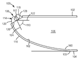
일 실시 형태에서, 본 발명은 중공의 광 공동(106)을 형성하도록 배치된 전방 반사기(102) 및 후방 반사기(104)와, 전방 반사기(102)의 일 단부에 근접하여 있고 5° 내지 90°의 경사각(110)을 갖는 제1 광원(108)과, 제1 광원(108)으로부터의 광을 중공의 광 공동(106) 내로 지향시키기 위해, 적어도 제1 광원(108)과 후방 반사기(104) 사이에서 연장되는 제1 비대칭 광 시준기(116)를 포함하는 백라이트를 제공한다.In one embodiment, the present invention provides a front reflector 102 and a back reflector 104 arranged to form a hollow optical cavity 106, and is in proximity to one end of the front reflector 102 and is between 5 ° and 90 °. A first light source 108 having an angle of inclination 110, and at least the first light source 108 and the back reflector 104 to direct light from the first light source 108 into the hollow light cavity 106. A backlight is provided that includes a first asymmetric light collimator 116 extending therebetween.
Description
본 발명은 통상 백라이트(backlight)로 지칭되는, 디스플레이 또는 그래픽을 조명하는 데 적합한 대면적 광원에 관한 것이다.The present invention relates to a large area light source suitable for illuminating a display or graphic, commonly referred to as a backlight.
백라이트는 LCD 컴퓨터 모니터, 이동 전화기 디스플레이, 개인 휴대 정보 단말기(personal digital assistant), 및 다른 핸드헬드(hand-held) 장치와 같은 디스플레이를 조명하는 데 사용된다. 중량을 줄이기 위한 노력으로, 중공(hollow) 백라이트가 개발되었다. 몇몇 중공 백라이트들은 광을 중공의 광 공동(hollow light cavity) 내로 지향시키도록 광원과 조합된, 대칭 포물선형 집중기(concentrator)를 포함한 대칭 집중기 또는 광 주입기(injector)를 이용하였다. 그러나, 그러한 광 주입기들은 대칭 광 주입기의 체적 때문에 디스플레이의 전체 크기를 증가시킨다. 디스플레이 크기의 증가는 대칭 광 주입기의 크기를 수용하는 데 요구되는 증가된 베젤(bezel) 폭에 기인한다.Backlights are used to illuminate displays such as LCD computer monitors, mobile phone displays, personal digital assistants, and other hand-held devices. In an effort to reduce weight, hollow backlights have been developed. Some hollow backlights used symmetric concentrators or light injectors, including symmetrical parabolic concentrators, combined with a light source to direct light into the hollow light cavity. However, such light injectors increase the overall size of the display because of the volume of the symmetric light injector. The increase in display size is due to the increased bezel width required to accommodate the size of the symmetric light injector.
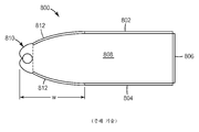
도 8은 대칭 광 주입기를 이용하는 종래 기술의 백라이트(800)를 도시한다. 백라이트(800)는 전방 반사기(802), 후방 반사기(804), 및 광 공동(808)을 한정하는 측면 반사기(806)를 갖는다. 광원(810)과 광 공동(808) 사이에서, 복합 포물선형 집중기(812)가 광원으로부터 광 공동 내로 광을 지향시킨다. 베젤 폭은 "W"로 식별된다.8 shows a
일 실시 형태에서, 본 발명은 중공의 광 공동을 형성하도록 배치된 전방 반사기 및 후방 반사기와, 전방 반사기의 일 단부에 근접하여 있고 5° 내지 90°의 경사각을 갖는 제1 광원과, 제1 광원으로부터의 광을 중공의 광 공동 내로 지향시키기 위해, 적어도 제1 광원과 후방 반사기 사이에서 연장되는 제1 비대칭 광 시준기(light collimator)를 포함하는 백라이트를 제공한다.In one embodiment, the invention provides a front reflector and a rear reflector arranged to form a hollow light cavity, a first light source proximate one end of the front reflector and having an inclination angle of 5 ° to 90 °, and a first light source In order to direct light from the hollow light cavity, there is provided a backlight comprising a first asymmetric light collimator extending between at least the first light source and the back reflector.
다른 실시 형태에서, 본 발명은 전방 반사기의 다른 단부에 근접하여 있고 5° 내지 90°의 경사각을 갖는 제2 광원; 및 제2 광원으로부터의 광을 중공의 광 공동 내로 지향시키기 위해, 제2 광원과 후방 반사기 사이에서 연장되는 제2 비대칭 광 시준기를 추가로 포함하는 상기 백라이트를 제공한다.In another embodiment, the present invention provides a light source comprising: a second light source proximate the other end of the front reflector and having an inclination angle of between 5 ° and 90 °; And a second asymmetric light collimator extending between the second light source and the back reflector to direct light from the second light source into the hollow light cavity.
다른 실시 형태들에서, 비대칭 광 시준기는 만곡되며, 비대칭 시준기는 포물선형이고, 광원과 전방 및 후방 반사기 사이에 배치된 하나보다 많은 비대칭 시준기가 있을 수 있으며, 광원은 CCFL 램프 또는 LED 다이(die)를 포함한다.In other embodiments, the asymmetric light collimator is curved, the asymmetric collimator is parabolic, and there can be more than one asymmetric collimator disposed between the light source and the front and back reflectors, the light source being a CCFL lamp or LED die It includes.
도 1은 백라이트의 일 실시 형태의 개략 단면도.
도 2는 백라이트의 일 실시 형태의 개략 단면도.
도 3은 백라이트의 일 실시 형태의 개략 단면도.
도 4는 광 디스플레이의 일 실시 형태의 개략 단면도.
도 5는 광 디스플레이의 일 실시 형태의 개략 단면도.
도 6은 휘도 대 수직 위치의 플롯(plot).
도 7은 백라이트의 일 실시 형태의 개략 단면도.
도 8은 종래 기술의 백라이트의 개략 단면도.1 is a schematic cross-sectional view of one embodiment of a backlight.
2 is a schematic cross-sectional view of one embodiment of a backlight.
3 is a schematic cross-sectional view of one embodiment of a backlight.
4 is a schematic cross-sectional view of one embodiment of an optical display.
5 is a schematic cross-sectional view of one embodiment of an optical display.
6 is a plot of luminance versus vertical position.
7 is a schematic cross-sectional view of one embodiment of a backlight.
8 is a schematic cross-sectional view of a backlight of the prior art.
다른 이점들 중에서, 본 발명의 백라이트는 중실 도광체(solid lightguide)를 포함하는 백라이트보다 더 경량이며, 의도된 응용에 적당한 휘도 및 공간적 균일성을 제공하면서 중공 에지형 백라이트(edge-lit backlight) 시스템의 베젤 폭을 줄이는 방식을 제공한다. 본 발명의 백라이트는 형광등 및 LED 광원 둘 모두에 대해 효용성을 갖는다. 그러한 백라이트는 LCD, 사인 박스(sign box) 및 조명 기구에서의 사용을 위한 유용성을 갖는다.Among other advantages, the backlight of the present invention is lighter than a backlight comprising a solid lightguide and provides a hollow edge-lit backlight system while providing adequate brightness and spatial uniformity for the intended application. Provides a way to reduce the bezel width. The backlight of the present invention has utility for both fluorescent and LED light sources. Such backlights have utility for use in LCDs, sign boxes, and luminaires.
본 발명의 백라이트의 일 실시 형태가 도 1에 도시되어 있다. 백라이트(100)는 중공의 광 공동(106)을 형성하는 방식으로 배치된 전방 반사기(102) 및 후방 반사기(104)를 포함한다. 본 실시 형태에서, 전방 반사기(102)는 평평하다. 다른 실시 형태들에서, 전방 반사기는 만곡되거나 곡률을 가질 수 있다. 광원(108)은 전방 반사기(102)에 근접하며, 전방 반사기(102)의 접선에 대한 광원의 위치는 경사각(110)에 의해 한정된다. 경사각(110)은 i) 전방 반사기의 평면에 대한 접선과 평행한 선(122), 및 ii) 광원의 개구면(aperture plane, 126)에 수직이면서 개구면을 이등분하는 선(124)의 교차점(128)에 의해 한정된다.One embodiment of the backlight of the present invention is shown in FIG. The
경사각은 대체로 5° 내지 90° 범위일 수 있으며, 5°와 90° 사이의 임의의 수 또는 범위일 수 있다. 다른 실시 형태들에서, 경사각은 15°, 30°, 45°, 60° 또는 90°, 또는 15°와 90° 사이의 임의의 수 또는 범위일 수 있다.The angle of inclination can generally range from 5 ° to 90 °, and can be any number or range between 5 ° and 90 °. In other embodiments, the inclination angle can be 15 °, 30 °, 45 °, 60 ° or 90 °, or any number or range between 15 ° and 90 °.
광원(108)은 광 요소(112), 광 요소 반사기(114), 및 광을 중공의 광 공동 내로 지향시키기 위한 비대칭 광 시준기(116)를 포함한다. 시준기들에 대하여 "비대칭"은 각각의 시준기가 광원에 대하여 상이하게, 예를 들어 상이한 길이(0의 길이를 포함함), 상이한 형상 또는 둘 모두를 갖는 것으로 형상화된 것을 의미한다. 제1 광 시준기(116)는 광원(108)과 후방 반사기(104) 사이에서 광 공동 내로 연장된다. 이 실시 형태에서, 제2 광 시준기는 광원(108)과 전방 반사기(102) 사이에서 어떠한 길이도 갖지 않는다. 이 실시 형태에서, 광 시준기(116)와 후방 반사기(104)는 일체형이다. 다른 실시 형태들에서, 광 시준기와 후방 반사기, 또는 이들의 일부분들은 별개의 구성요소들일 수 있거나 상이한 재료로 제조될 수 있다.The
광 시준기(116)와 후방 반사기 사이의 경계는 광 시준기에 대한 접선이 수평인 곳(105)이다.The boundary between the
도 1에 도시된 바와 같이, 광 시준기(116)는 만곡되거나 곡률을 갖는다. 전방 반사기(102)와 부딪히는 광이 비교적 큰 입사각을 갖는 것이 바람직하다. 따라서, 광선은 바람직하게는 접선(122)으로부터 비교적 작은 각도로 광원으로부터 제공된다. 그러나, 광의 일부는 접선(122)으로부터 비교적 큰 각도로 전달될 수 있다. 이러한 경우에, 만곡된 광 시준기는 그러한 광을 반사시켜, 그러한 광이 비교적 큰 입사각으로 전방 반사기(122)와 부딪히게 한다. 다른 실시 형태들에서, 광 시준기(116)의 곡률은 그 정점(vertex)이 개구면(126)의 교점에 위치되고 그 초점이 개구면(126)과 전방 반사기(102)의 교점에 위치되는 포물선으로서 기술될 수 있다. 따라서, 포물선의 축은 바람직하게는 개구면(126)에 평행하다. 이 실시 형태에서, 광 요소는 냉음극 형광 램프(cold cathode fluorescent lamp, CCFL)이며, 광 요소 반사기는 한 쌍의 인벌류트(involute; 118, 120)로서 기술될 수 있다.As shown in FIG. 1, the
다른 실시 형태들에서, 광 요소 반사기는 광 요소를 둘러싸는 임의의 일반적인 형상에 의해 기술될 수 있다. 그러한 형상은 달걀형, 직사각형 또는 사다리꼴인 단면을 포함하지만 이로 한정되지 않는다.In other embodiments, the light element reflector may be described by any general shape surrounding the light element. Such shapes include, but are not limited to, oval, rectangular or trapezoidal cross sections.
몇몇 응용에서, 광 요소들은 예를 들어 경사각이 90°일 때 전방 반사기로의 직접적인 목시선(line of sight)을 갖지 않는 것이 바람직하다. 그러한 경우에, 광 요소 및 기존의 광 요소 반사기는 광 요소 반사기가 전방 반사기와 교차하는 지점을 중심으로 추가로 회전할 수 있다. 이때, 광 요소 반사기는 전방 반사기로부터의 광 요소 반사기의 원위 단부(distal end)와 후방 반사기 사이에서 반사성 연장부를 가질 수 있다. 그 연장부는 평평하거나 만곡될 수 있다. 일 실시 형태에서, 연장부는 원호이다.In some applications, it is desirable that the light elements do not have a direct line of sight to the front reflector, for example when the tilt angle is 90 °. In such a case, the light element and existing light element reflector may be further rotated about the point where the light element reflector intersects with the front reflector. The light element reflector can then have a reflective extension between the distal end of the light element reflector from the front reflector and the back reflector. The extension can be flat or curved. In one embodiment, the extension is an arc.
다른 실시 형태들에서, 광 요소는 광 요소 반사기를 갖거나 갖지 않는 LED 또는 일렬의 LED들일 수 있다. 게다가, LED들은 각각에 근접하여 그리고 각각과 중공 공동 사이에서 광 추출 및/또는 광 시준을 보조하는 굴절성 렌즈 요소를 가질 수 있다. 부가적으로, LED 또는 존재한다면 굴절성 렌즈 요소와 시준기 사이에서 연장되는 광 요소 반사기가 있을 수 있다. 이들 광 요소 반사기는 평평할 수 있거나, 만곡 단면을 가질 수 있다. 바람직하게는, 히트 싱크(heat sink), 예를 들어 광원 둘레를 감싸고 시준기의 일부 위에서 연장되는 히트 싱크가 LED 광 요소와 함께 사용되어 LED로부터 멀리 열을 끌어낼 수 있다.In other embodiments, the light element may be an LED or a series of LEDs with or without a light element reflector. In addition, the LEDs may have refractive lens elements that assist light extraction and / or light collimation in proximity to each other and between each and the hollow cavities. In addition, there may be an LED or an optical element reflector extending between the refractive lens element and the collimator, if present. These light element reflectors may be flat or may have a curved cross section. Preferably, a heat sink, for example a heat sink that wraps around the light source and extends over a portion of the collimator, can be used with the LED light element to draw heat away from the LED.
원하다면, 열음극 형광 램프(hot cathode fluorescent lamp, HCFL), 외부 전극 형광 램프(external electrode fluorescent lamp, EEFL) 또는 광 파이프(예를 들어, 미국 특허 제6,267,492호에 기술됨)와 같은 다른 가시광 이미터(emitter)가 개시된 백라이트를 위한 광원에서 사용될 수 있다. 게다가, 예를 들어 상이한 스펙트럼을 방출하는 것과 같은 냉백색 및 온백색, CCFL/HCFL/EEFL을 포함하는 (CCFL/LED)와 같은 복합 시스템이 사용될 수 있다. 광 이미터들의 조합은 광범위하게 변할 수 있으며, LED들 및 CCFL들, 그리고 예를 들어 다수의 CCFL, 상이한 색상의 다수의 CCFL, 및 LED와 CCFL와 같은 복수개를 포함할 수 있다.If desired, other visible light emitters, such as hot cathode fluorescent lamps (HCFLs), external electrode fluorescent lamps (EEFLs) or light pipes (e.g., described in US Pat. No. 6,267,492). Emitters can be used in the light source for the disclosed backlight. In addition, complex systems such as cold white and warm white, such as emitting different spectra, (CCFL / LED) including CCFL / HCFL / EEFL can be used. The combination of light emitters can vary widely and can include LEDs and CCFLs, and, for example, multiple CCFLs, multiple CCFLs of different colors, and a plurality of such as LEDs and CCFLs.
형광 램프와 함께 사용되는 광 요소 반사기는 바람직하게는 도 1에 도시된 바와 같이 형광등의 원형 단면의 한 쌍의 인벌류트 형태로 형상화될 수 있다.The light element reflector used with the fluorescent lamp may preferably be shaped in the form of a pair of involutes in the circular cross section of the fluorescent lamp as shown in FIG. 1.
본 발명의 백라이트(200)의 다른 실시 형태가 도 2에 도시되어 있다. 백라이트(200)는 중공의 광 공동(206)을 형성하는 방식으로 배치된 전방 반사기(202) 및 후방 반사기(204)를 포함한다. 광원(208)은 전방 반사기(202)에 근접하여 있으며, 전방 반사기(202)에 대한 그의 위치는 위에서 정의된 바와 같은 경사각(210)에 의해 한정된다. 광원(208)은 광 요소(212), 광 요소 반사기(214), 및 광을 중공의 광 공동(206)으로 보내기 위한 제1 및 제2 비대칭 광 시준기(216, 217)를 포함한다. 광 시준기(216)와 후방 반사기 사이의 경계는 광 시준기에 대한 접선이 수평인 곳(205)이다. 광 시준기(217)는 광 시준기(216)보다 대체로 더 작은 길이를 가지며 광원(208)과 전방 반사기(202) 사이에서 연장된다.Another embodiment of the
광 시준기(217)는 평평하거나 곡률을 가질 수 있다. 전방 반사기(202)와 부딪히는 광이 비교적 큰 입사각을 갖는 것이 바람직하다. 경사각(210)이 작아서, 요구되는 것보다 더 큰 각도로 전방 반사기(202)와 부딪히게 될 전방으로 전파되는 일부 광이 있다면, 광 시준기(217)는 후방 반사기(204) 또는 광 시준기(216)로부터의 반사시 광선이 요구되는 각도로 전방 반사기(202)와 부딪히게 할 각도로 그리고 하방으로 광을 반사적으로 방향전환시키도록 위치될 수 있다. 따라서, 광 시준기(216, 217)에 의해 제공되는 광 시준은 광원으로부터 바람직하게는 작은 각도로 전방 반사기(202)에 광선을 제공한다. 다른 실시 형태들에서, 광 시준기(217)의 곡률은 포물선 섹션으로서 기술될 수 있다. 이 실시 형태에서, 광 요소는 냉음극 형광 램프(CCFL)이며, 광 요소 반사기(214)는 한 쌍의 인벌류트로서 기술될 수 있다.The
본 발명의 백라이트(300)의 다른 실시 형태가 도 3에 도시되어 있다. 백라이트(300)는 중공의 광 공동(306)을 형성하는 방식으로 배치된 전방 반사기(302) 및 후방 반사기(304)를 포함한다. 제1 및 제2 광원(208, 210) 각각은 전방 반사기(302)에 근접하여 있으며, 전방 반사기에 대한 그들의 위치는 경사각(312)에 의해 한정된다. 각각의 광원은 2개의 광 요소(314)들, 광 요소 반사기(316), 및 광을 중공의 광 공동(306) 내로 지향시키기 위한 각각의 광원용 광 시준기(318, 320)를 포함한다. 광 시준기(318)와 후방 반사기 사이의 경계는 광 시준기에 대한 접선이 수평인 곳(305)이다.Another embodiment of the
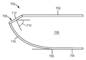
본 발명의 백라이트(700)의 다른 실시 형태가 도 7에 도시되어 있다. 백라이트(700)는 중공의 광 공동(706)을 형성하는 방식으로 배치된 전방 반사기(702) 및 후방 반사기(704)를 포함한다. 광원(708)은 전방 반사기(702)에 근접하여 있으며, 전방 반사기(702)에 대한 그의 위치는 위에서 정의된 바와 같은 경사각(710)에 의해 한정된다. 광원(208)은 LED 다이(712), 및 중공의 광 공동(706) 내로 광을 지향시키기 위한 제1 비대칭 광 시준기(716)를 포함한다. 광 시준기(716)와 후방 반사기 사이의 경계는 광 시준기에 대한 접선이 수평인 곳(705)이다.Another embodiment of the
후방 반사기와 광 시준기 둘 모두는 중공의 광 공동 내로 향하는 고반사성 표면을 제공하는 시트(sheet) 재료를 포함하는데, 반사성 표면(160, 162)은 넓어진 반사된 빔(beam)으로의 입사광 빔의 제한되고 조절된 퍼짐을 야기할 수 있다. 이러한 유형의 재료는 "산란 반사성 재료(scattering reflective material)"라는 일반적인 용어로 알려져 있으며, 반사된 빔의 각도 퍼짐(angular spread)에 따라 "넓은" 또는 "좁은" 산란 반사성 재료로 추가로 분류될 수 있다(문헌["Daylighting in Architecture - A European Reference Book", published by James and James, London, 1993. ISBN 1-873936-21-4, at pages 4.3 to 4.5] 참조). 일반적으로, 반사성 표면(160, 162)은 좁은 산란 반사기(약 15° 미만 또는 본 응용에 대해 더 전형적으로는 약 5° 내지 15°의 분산각(dispersion angle)을 갖는 것을 의미함)를 포함하지만, 표면에 수직이 아닌 방향으로 입사되는 광에 대해 그 반사도가 실질적으로 감소되지 않고 적어도 85%(바람직하게는 적어도 90%, 가장 바람직하게는 적어도 98%)이도록 하는 것이어야 한다.Both the back reflector and the light collimator comprise a sheet material that provides a highly reflective surface directed into the hollow optical cavity, wherein the
"분산각"은, 반사광의 최대 강도(maximum intensity)(Imax)의 방향에 대하여 대칭인 반사광 분포 곡선의 강도를 가정하면, Imax의 방향과 Imax/2의 값을 갖는 강도의 방향 사이의 각도를 의미한다. 반사광의 강도 분포 곡선이 Imax의 방향에 대하여 대칭이 아니면, 본 명세서에 사용된 바와 같은 용어 "분산각"은 Imax의 방향과 Imax/2 강도의 방향 사이의 평균 각도를 의미한다. 넓어진 반사된 빔은 최대 강도의 방향으로 뚜렷한 피크(peak)를 나타내거나 나타내지 않을 수 있다."Dispersion angle" is the maximum intensity of the reflected light (maximum intensity), assuming the intensity of the symmetrical reflected light distribution curve with respect to a direction of (I max), between the direction of intensity with a direction and a value of I max / 2 in I max Means the angle. The intensity distribution curve of the reflected light is not a symmetry with respect to the direction of I max, the term "dispersion angle" as used herein means the mean angle between the direction of I max and I max / 2 strength direction. The broadened reflected beam may or may not exhibit a pronounced peak in the direction of maximum intensity.
적합한 고반사도 재료의 예는 쓰리엠 컴퍼니(3M Company)로부터 입수가능한 비퀴티(VIKUITI)™ 인핸스드 스펙큘러 리플렉터(Enhanced Specular Reflector, ESR) 다층 중합체 필름; 0.01 ㎜(0.4 밀(mil)) 두께의 아이소옥틸아크릴레이트 아크릴산 감압 접착제를 사용하여 비퀴티 ESR 필름에 황산바륨이 로딩된 폴리에틸렌 테레프탈레이트 필름(0.05 ㎜(2 밀) 두께)을 라미네이팅함으로써 제조된 필름(이 생성된 라미네이트 필름은 본 명세서에서 "EDR II" 필름으로 불림); 도레이 인더스트리즈, 인크.(Toray Industries, Inc.)로부터 입수가능한 E-60 시리즈 루미러(LUMIRROR)™ 폴리에스테르 필름; 알라노드 알루미늄-페레드룽 게엠베하 앤드 컴퍼니(Alanod Aluminum-Veredlung GmbH & Co.)로부터 입수가능한 미로(MIRO)™ 양극산화 알루미늄 필름(미로™ 2 필름을 포함함); 및 쓰리엠 컴퍼니로부터 입수가능한 실버룩스(SILVERLUX) 및/또는 ECP 305+ 솔라(Solar) 필름을 포함한다.Examples of suitable high reflectivity materials include VIKUITI ™ Enhanced Specular Reflector (ESR) multilayer polymer films available from 3M Company; Prepared by laminating a polyethylene terephthalate film (0.05 mm (2 mil) thick) loaded with barium sulfate on a non-quity ESR film using a 0.4 mil isooctylacrylate acrylic acid pressure sensitive adhesive Films (the resulting laminate films are referred to herein as "EDR II" films); E-60 Series LUMIRROR ™ Polyester Films available from Toray Industries, Inc .; MIRO ™ anodized aluminum film (including Maze ™ 2 film) available from Alanod Aluminum-Veredlung GmbH & Co .; And SILVERLUX and / or
중공의 광 공동을 향하는 후방 반사기의 반사성 표면은 실질적으로 평탄하고 매끄럽거나, 광 산란 또는 혼합을 증진시키기 위해 그와 관련된 구조화된(structured) 표면을 가질 수 있다. 그러한 구조화된 표면은 (a) 후방 반사기 또는 시준기, 또는 둘 모두의 반사성 표면(160) 상에, 또는 (b) 표면에 도포된 투명 코팅 상에 부여될 수 있다. 전자의 경우에, 구조화된 표면이 이미 형성된 기판에 고반사 필름이 라미네이팅될 수 있거나, 고반사 필름이 (쓰리엠 컴퍼니로부터 입수가능한 비퀴티™ 듀라블 인핸스드 스펙큘러 리플렉터-메탈(Durable Enhanced Specular Reflector-Metal, DESR-M) 반사기와 같이 얇은 금속 시트와 같은) 평탄한 기판에 라미네이팅되고 이어서 예컨대 스탬핑(stamping) 작업에 의해 구조화된 표면이 형성될 수 있다. 후자의 경우, 구조화된 표면을 갖는 투명 필름이 평탄한 반사성 표면에 라미네이팅되거나, 투명한 필름이 반사기에 도포된 후에 구조화된 표면이 투명한 필름의 상부에 부여되거나, 또는 반사성 금속 코팅이 예를 들어 구조화된 표면을 갖는 투명 필름의 구조화된 면 또는 평평한 면 어느 쪽에 증발 코팅에 의해 도포될 수 있다.The reflective surface of the back reflector facing the hollow light cavity may be substantially flat and smooth, or have a structured surface associated therewith to enhance light scattering or mixing. Such structured surface may be imparted on (a) the
다른 실시 형태에서, 후방 반사기는 반-경면(semi-specular) 반사기일 수 있다. "반-경면 반사기"는 역방향 산란보다는 실질적으로 더 많은 전방 산란을 반사시키는 반사기를 지칭한다. 본 발명의 후방 반사기에 대해 임의의 적합한 반-경면 재료 또는 재료들이 사용될 수 있다. 예를 들어, 반-경면 후방 반사기는 고반사 확산 반사기 상에 부분 투과성 경면 반사기를 포함할 수 있다. 적합한 반-경면 반사기는, 후술되는, 제1 면 또는 주 표면(major surface) 상에 긴 렌즈형 특징부 구조물을 갖는 선형 렌즈 필름에 근접하여 ESR(쓰리엠 컴퍼니로부터 입수가능함)을 포함한다. 선형 렌즈 필름은 전방 반사기와 후방 반사기 사이에 놓이며, 그 렌즈형 특징부는 광 요소에 평행하게 연장된다.In another embodiment, the back reflector may be a semi-specular reflector. "Semi-mirror reflector" refers to a reflector that reflects substantially more forward scattering than reverse scattering. Any suitable semi-mirror material or materials can be used for the back reflector of the present invention. For example, the semi-mirror back reflector may include a partially transmissive mirror reflector on the high reflection diffuse reflector. Suitable semi-mirror reflectors include ESR (available from 3M Company) in proximity to a linear lens film having elongated lenticular feature structures on the first or major surface, described below. The linear lens film lies between the front reflector and the back reflector, the lenticular features extending parallel to the light element.
미세복제된 렌즈형 특징부들은 길며, 많은 실시 형태들에서 서로 평행하게 배치된다. 많은 실시 형태들에서, 렌즈형 특징부는 수직 방향으로의 굴절력(optical power) 및 직교하는 수평 방향으로의 무시할만한 굴절력을 갖는다.The microreplicated lenticular features are long and in many embodiments are arranged parallel to each other. In many embodiments, the lenticular features have optical power in the vertical direction and negligible refractive power in the orthogonal horizontal direction.
일 실시 형태에서, 렌즈형 특징부는 1 내지 250 마이크로미터, 10 내지 100 마이크로미터 또는 25 내지 75 마이크로미터 범위의 곡률 반경을 갖는다. 이들 프리즘 특징부는 1 내지 250 마이크로미터, 또는 1 내지 75 마이크로미터, 또는 5 내지 50 마이크로미터 범위의 높이를 갖는다. 많은 실시 형태들에서, 전술된 평행한 긴 렌즈형 특징부는 1 내지 1000 마이크로미터, 또는 1 내지 500 마이크로미터, 또는 1 내지 250 마이크로미터, 또는 1 내지 100 마이크로미터, 또는 10 내지 75 마이크로미터 범위의 주기 또는 피치를 갖는다.In one embodiment, the lenticular features have a radius of curvature in the range of 1 to 250 micrometers, 10 to 100 micrometers or 25 to 75 micrometers. These prismatic features have a height in the range of 1 to 250 micrometers, or 1 to 75 micrometers, or 5 to 50 micrometers. In many embodiments, the parallel elongated lenticular features described above range from 1 to 1000 micrometers, or from 1 to 500 micrometers, or from 1 to 250 micrometers, or from 1 to 100 micrometers, or from 10 to 75 micrometers. Have a period or pitch.
다른 실시 형태에서, 반-경면 후방 반사기는 고반사 경면 반사기 상에 부분 램버시안 확산기(Lambertian diffuser)를 포함할 수 있다. 대안적으로, 고반사 경면 반사기 상의 전방 산란 확산기가 반-경면 후방 반사기를 제공할 수 있다. 다른 적합한 반-경면 반사기는 미국 미네소타주 세인트 폴 소재의 쓰리엠 컴퍼니로부터 상표명 "라디언트 라이트 필름 엠보스드(RADIANT LIGHT FILM EMBOSSED) VM2000"으로 입수가능한 샌드-블라스트(sand-blast) 패턴으로 엠보싱 필름 재료이다.In another embodiment, the semi-mirror back reflector may include a partial Lambertian diffuser on the high reflecting mirror reflector. Alternatively, a forward scattering diffuser on the highly reflective mirror reflector may provide a semi-mirror back reflector. Another suitable semi-mirror reflector is an embossed film material in a sand-blast pattern available under the trade name "RADIANT LIGHT FILM EMBOSSED VM2000" from 3M Company, St. Paul, Minn. .
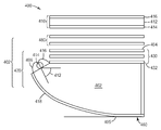
본 명세서에 언급된 바와 같이, 본 발명의 백라이트는 디스플레이 시스템을 위한 백라이트로서 사용될 수 있다. 도 4는 광학 디스플레이(400)의 일 실시 형태의 개략 단면도이다. 디스플레이(400)는 액정 패널(410) 및 광을 LC 패널(410)에 제공하도록 위치된 조명 조립체(402)를 포함한다. 이 실시 형태에서, 조명 조립체(402)는 백라이트(420)를 포함하며, 광학 필름과 같은 추가의 광 관리 구성요소(480)를 포함할 수 있다.As mentioned herein, the backlight of the present invention can be used as a backlight for a display system. 4 is a schematic cross-sectional view of one embodiment of an
도 4에 도시된 바와 같이, LC 패널(410)은 액정 층(412), 입사 플레이트(entry plate)(414), 및 출사 플레이트(exit plate, 416)를 포함한다. 유리 기판을 각각 포함할 수 있는 입사 및 출사 플레이트(414, 416)는 전극 매트릭스(electrode matrix), 정렬 층, 편광기, 보상 필름, 보호 층, 및 기타 층을 각각 포함할 수 있다. 컬러 필터 어레이가 또한 LC 패널(410)에 의해 디스플레이되는 이미지에 색상을 부여하기 위해 플레이트(414, 416)들 중 어느 하나 또는 둘 모두에 포함될 수 있다. LC 패널(410)에서, 액정 층(412)의 부분들은 전극 매트릭스를 통해 인가된 전기장에 의해 변경되는 그들의 광학적 상태를 갖는다. 그 상태에 따라, 액정 층(412)의 주어진 부분(디스플레이(400)의 픽셀 또는 서브픽셀에 대응함)은 그를 통해 투과되는 광의 편광을 더 크거나 더 작은 크기로 회전시킬 것이다. 입사 플레이트(414)의 입사 편광기, 액정 층(412), 출사 플레이트(416)의 출사 편광기를 통해 진행하는 광은 편광기의 배향 및 광이 마주치는 액정 층의 부분의 광학적 상태에 따라 다양한 정도로 감쇠된다. 디스플레이(400)는 상이한 면적에서 상이하게 나타나는 전자적으로 제어가능한 디스플레이를 제공하기 위해 이러한 거동을 이용한다.As shown in FIG. 4, the
광 관리 유닛으로도 지칭될 수 있는 광 관리 구성요소(480)의 배열이 백라이트(420)와 LC 패널(410) 사이에 위치될 수 있다. 광 관리 구성요소(480)는 백라이트(420)로부터 전파되는 조명 광에 영향을 준다. 예를 들어, 광 관리 구성요소(480)의 배열은 확산기 층 또는 단순히 확산기를 포함할 수 있다. 확산기는 백라이트(420)로부터 수광된 광을 확산시키는 데 사용된다.An array of
확산기는 임의의 적합한 확산기 필름 또는 플레이트일 수 있다. 예를 들어, 확산기 층은 임의의 적합한 확산 재료 또는 재료들을 포함할 수 있다. 몇몇 실시 형태에서, 확산기 층은 유리, 폴리스티렌 비드(bead) 및 CaCO3 입자를 포함하는 다양한 분산 상을 가진 폴리메틸 메타크릴레이트(PMMA)의 중합체 매트릭스를 포함할 수 있다. 예시적인 확산기는 미국 미네소타주 세인트 폴 소재의 쓰리엠 컴퍼니로부터 입수가능한, 쓰리엠(3M)™ 스카치칼™ 디퓨저 필름(Scotchcal™ Diffuser Film), 타입 3635-30, 3635-70 및 3635-100을 포함할 수 있다.The diffuser can be any suitable diffuser film or plate. For example, the diffuser layer may comprise any suitable diffuser material or materials. In some embodiments, the diffuser layer may comprise a polymer matrix of polymethyl methacrylate (PMMA) having various dispersed phases, including glass, polystyrene beads, and CaCO 3 particles. Exemplary diffusers may include 3M ™ Scotchcal ™ Diffuser Films, types 3635-30, 3635-70, and 3635-100, available from 3M Company, St. Paul, Minn., USA. have.
선택적인 광 관리 구성요소(480)는 또한 반사 편광기를 포함할 수 있다. 임의의 적합한 유형의 반사 편광기, 예를 들어 다층 광학 필름(multilayer optical film, MOF) 반사 편광기; 확산 반사 편광 필름(diffusely reflective polarizing film, DRPF), 예컨대 연속/분산 상 편광기; 와이어 그리드 반사 편광기; 또는 콜레스테릭 반사 편광기가 사용될 수 있다.Optional
MOF 및 연속/분산 상 반사 편광기 둘 모두는 광을 직교 편광 상태로 투과시키면서 하나의 편광 상태의 광을 선택적으로 반사시키기 위해 적어도 2종의 재료, 보통 중합체 재료들 간의 굴절률 차이에 의존한다. MOF 반사 편광기의 몇몇 예는 공동 소유의 미국 특허 제5,882,774호(존자(Jonza) 등)에 기술되어 있다. MOF 반사 편광기의 구매가능한 예는 쓰리엠 컴퍼니로부터 입수가능한, 확산 표면을 포함하는 비퀴티™ DBEF-D280 및 DBEF-D400 다층 반사 편광기를 포함한다.Both MOF and continuous / disperse phase reflective polarizers rely on the difference in refractive index between at least two materials, usually polymeric materials, to selectively reflect light in one polarization state while transmitting light in an orthogonal polarization state. Some examples of MOF reflective polarizers are described in commonly owned US Pat. No. 5,882,774 (Jonza et al.). Commercially available examples of MOF reflective polarizers include Viquity ™ DBEF-D280 and DBEF-D400 multilayer reflective polarizers, including diffusion surfaces, available from 3M Company.
본 발명과 관련하여 유용한 DRPF의 예는, 예를 들어 공동 소유의 미국 특허 제5,825,543호(오우더키르크(Ouderkirk) 등)에 기술된 바와 같은 연속/분산 상 반사 편광기, 및 예를 들어 공동 소유의 미국 특허 제5,867,316호(칼슨(Carlson) 등)에 기술된 바와 같은 확산 반사 다층 편광기를 포함한다. 다른 적합한 유형의 DRPF가 미국 특허 제5,751,388호(라슨(Larson))에 기술되어 있다.Examples of DRPFs useful in connection with the present invention are continuous / disperse phase reflective polarizers as described, for example, in co-owned US Pat. No. 5,825,543 (Ouderkirk et al.), And co-owned, for example Diffusely reflective multilayer polarizers as described in US Pat. No. 5,867,316 (Carlson et al.). Another suitable type of DRPF is described in US Pat. No. 5,751,388 (Larson).
본 발명과 관련하여 유용한 와이어 그리드 편광기의 몇몇 예는, 예를 들어 미국 특허 제6,122,103호(퍼킨스(Perkins) 등)에 기술된 것들을 포함한다. 와이어 그리드 편광기는 특히 미국 유타주 오렘 소재의 목스텍 인크.(Moxtek Inc.)로부터 입수가능하다.Some examples of wire grid polarizers useful in connection with the present invention include those described, for example, in US Pat. No. 6,122,103 (Perkins et al.). Wire grid polarizers are especially available from Moxtek Inc. of Orem, Utah, USA.
본 발명과 관련하여 유용한 콜레스테릭 편광기의 몇몇 예는, 예를 들어 미국 특허 제5,793,456호(브로어(Broer) 등) 및 미국 특허 제6,917,399호(포코니(Pokorny) 등)에 기술되어 있는 것들을 포함한다. 콜레스테릭 편광기는 종종 출력 측의 사분파(quarter wave) 지연 층과 함께 제공되어, 콜레스테릭 편광기를 통해 투과된 광이 선형 편광된 광으로 변환되도록 한다.Some examples of cholesteric polarizers useful in connection with the present invention are described, for example, in US Pat. No. 5,793,456 (Broer et al.) And US Pat. No. 6,917,399 (Pokorny et al.). Include. A cholesteric polarizer is often provided with a quarter wave retardation layer on the output side, allowing the light transmitted through the cholesteric polarizer to be converted into linearly polarized light.
몇몇 실시 형태에서, 편광 제어 층이 백라이트(420)와 반사 편광기 사이에 제공될 수 있다. 편광 제어 층의 예는 사분파 지연 층 및 액정 편광 회전 층과 같은 편광 회전 층을 포함한다. 편광 제어 층은 반사 편광기로부터 반사되는 광의 편광을 변경시키는 데 사용될 수 있어서, 증가된 분율의 재순환된 광이 반사 편광기를 통해 투과된다.In some embodiments, a polarization control layer can be provided between the
광 관리 구성요소(480)의 선택적인 배열은 또한, 지향성 재순환 층 또는 필름으로도 지칭되는, 하나 이상의 휘도 향상 층 또는 필름을 포함할 수 있다. 휘도 향상 층은 디스플레이의 법선 축에 더 가까운 방향으로 축외(off-axis) 광을 방향전환시키는 표면 구조물을 포함하는 것이다. 이는 LC 패널(410)을 통해 축상(on-axis) 전파되는 광의 양을 증가시키며, 따라서 관찰자가 보는 이미지의 휘도 및 콘트라스트(contrast)가 증가된다. 휘도 향상 층의 일례는 프리즘형 휘도 향상 층인데, 이는 굴절과 반사를 통해 조명 광을 방향전환시키는 다수의 프리즘형 리지(ridge)를 갖는다. 디스플레이 시스템(100)에 사용될 수 있는 프리즘형 휘도 향상 층의 예는 BEF II 90/24, BEF II 90/50, BEF IIIM 90/50 및 BEF IIIT를 포함한, 쓰리엠 컴퍼니로부터 입수가능한 비퀴티™ BEF II 및 BEF III 계열의 프리즘형 필름을 포함한다. 휘도 향상은 또한 본 명세서에서 추가로 기술되는 바와 같이 전방 반사기의 실시 형태들 중 일부에 의해 제공될 수 있다.The optional arrangement of the
광 관리 구성요소(480)의 선택적 배열은 또한 이득 확산기와 같은 다른 지향성 재순환 필름을 포함할 수 있으며, 필름 또는 층의 하나 또는 둘 모두의 주 표면 상에 규칙적이거나 불규칙적인 행렬로 배열된 비드, 둥근 돔(dome), 피라미드 또는 기타 돌출 구조물과 같은 구조물을 포함한다.The optional arrangement of the
도 4에 도시된 실시 형태의 디스플레이 시스템(400)은 백라이트(420)를 포함한다. 백라이트(420)는 중공의 광 공동(462)을 형성하는 전방 반사기(430) 및 후방 반사기(460)를 포함한다. 공동(462)은 출력 표면(464)을 포함한다. 출력 표면(464)은 임의의 적합한 형상, 예컨대 직사각형일 수 있으며, 예를 들어 대각선이 대략 30 ㎜의 치수를 갖는 이동 전화기를 위한 서브디스플레이로부터 대각선이 대략 30 ㎝의 치수를 갖는 랩톱 컴퓨터 스크린, 대각선이 대략 50 ㎝, 80 ㎝, 100 ㎝, 150 ㎝, 또는 그보다 더 큰 모니터 또는 텔레비전에 이르는 범위의, 임의의 원하는 디스플레이 응용에 사용가능한 크기의 것일 수 있다. 본 실시 형태에서, 백라이트(420)는 공동(462) 내로 광을 방출하도록 배치된 단일 광원(466)을 포함한다. 광원(466)은 전방 반사기(430)에 근접하여 있으며, 전방 반사기(430)에 대한 그의 위치는 경사각(412)에 의해 한정된다. 광원(466)은 광 요소(414), 광 요소 반사기(416), 및 광을 중공의 광 공동(462) 내로 지향시키기 위한 비대칭 광 시준기(418)를 포함한다. 본 실시 형태에서, 백라이트(420)는 광원을 포함하지 않는 측에서 중공의 광 공동(462)의 주연부(periphery)를 둘러싸는 측면 반사기 또는 표면(468)을 포함할 수 있다. 후방 반사기(460)를 위한 사용된 동일한 반사성 재료가 이들 벽을 형성하기 위해 사용될 수 있거나, 상이한 반사성 재료가 사용될 수 있다.The
도 4의 디스플레이(400)의 백라이트(420)는 복수의 지향성 재순환 필름 또는 층(432)을 포함하는 전방 반사기(430)를 포함한다. 다른 실시 형태들에서, 단일 지향성 재순환 필름 또는 층이 사용된다. 지향성 재순환 필름은 디스플레이의 축에 더 근접하는 방향으로 축외 광을 방향전환시키는 표면 구조물을 일반적으로 포함하는 광학 필름이다. 이는 LC 패널(410)을 통해 축상 전파되는 광의 양을 증가시키며, 따라서 관찰자가 보는 이미지의 휘도 및 콘트라스트가 증가된다. 지향성 재순환 필름은 전형적으로 중공의 광 공동(462)으로부터 그에 입사하는 광 중 상당한 분율을 다시 중공의 광 공동 내로 복귀시키거나 재순환시킨다. 지향성 재순환 필름은 또한 휘도 향상 필름 또는 층으로 지칭될 수 있다. 몇몇 지향성 재순환 필름은 광을 방향전환시키는 긴 프리즘들의 어레이를 포함할 수 있다. 다른 지향성 재순환 필름은 이득 확산기로 지칭될 수 있으며, 필름 또는 층의 하나 또는 양 주 표면 상에 규칙적인 또는 불규칙적인 매트릭스 어레이로 배열되는 비드, 둥근 돔, 피라미드 또는 기타 돌출 구조물과 같은 구조물을 포함할 수 있다.The
전방 반사기는 공동 내에서 비교적 높은 재순환을 지원하기 위해 비교적 높은 전체 반사율을 갖는다. 이는, 광이 모든 가능한 방향으로부터 구성요소(표면, 필름, 또는 필름들의 집합체 중 어느 것)에 입사할 때 그 구성요소 또는 구성요소들의 적층체의 전체 반사율을 의미하는 "반구 반사율"에 의해 특징지어질 수 있다. 따라서, 이 구성요소는 법선 방향을 중심으로 한 반구 내에서 모든 방향(및 달리 명시되지 않는 한, 모든 편광 상태)으로부터 입사하는 (의도된 응용에 대해 적절한 스펙트럼 분포를 가진) 광에 의해 조명되며, 이러한 동일한 반구 내로 반사된 모든 광이 집광된다. 입사 광의 총 광속(total flux)에 대한 반사된 광의 총 광속의 비가 반구 반사율 Rhemi를 생성한다. 반사기를 그의 Rhemi에 의해 특징지우는 것은 재순환 공동에 대해 특히 편리한데, 이는 광이 대체로 공동의 내부 표면 - 전방 반사기, 후방 반사기, 또는 측면 반사기 중 어느 것 - 에 모든 각도에서 입사하기 때문이다. 또한, 수직 입사에 대한 반사율과 달리, Rhemi는 몇몇 구성요소(예를 들어, 프리즘형 필름)에 대해 매우 중요할 수 있는 입사각에 따른 반사율의 변동성을 고려한다.The front reflector has a relatively high overall reflectance to support relatively high recycling in the cavity. This is characterized by "semi-spherical reflectivity", which means the total reflectance of a component or a stack of components when light is incident on a component (either surface, film, or a collection of films) from all possible directions. Can lose. Thus, this component is illuminated by light (with an appropriate spectral distribution for the intended application) incident from all directions (and all polarization states, unless otherwise specified) within the hemisphere about the normal direction, All light reflected into this same hemisphere is condensed. The ratio of the total light flux of reflected light to the total flux of incident light produces the hemispherical reflectivity R hemi . Characterizing the reflector by its R hemi is particularly convenient for the recycling cavity, since light is generally incident at all angles to the interior surface of the cavity—either the front reflector, the back reflector, or the side reflector. Also, unlike reflectance for normal incidence, R hemi takes into account the variability of reflectivity with respect to the angle of incidence, which can be very important for some components (eg, prismatic films).
바람직한 후방 반사기는 또한 높은 - 전형적으로는 전방 반사기보다 훨씬 더 높은 - 반구 반사율을 갖는데, 이는 전방 반사기가 의도적으로 백라이트의 요구되는 광 출력을 제공하기 위해 부분적으로 투과성이 되도록 설계되기 때문이다. 재순환 백라이트 구성은 전방 및 후방 반사기 둘 모두에 대한 반구 반사율, 각각 Rf hemi 및 Rb hemi의 곱에 의해 특징지어질 수 있다. 바람직하게는, 곱 Rf hemi * Rb hemi는 적어도 70% (0.70), 또는 75%, 또는 80%이다.Preferred back reflectors also have high hemisphere reflectivity—typically much higher than front reflectors because the front reflector is intentionally designed to be partially transmissive to provide the required light output of the backlight. The recycle backlight configuration can be characterized by the product of hemisphere reflectivity for both the front and back reflectors, R f hemi and R b hemi , respectively. Preferably, the product R f hemi * R b hemi is at least 70% (0.70), or 75%, or 80%.
본 발명의 백라이트에 사용되는 전방 반사기는 2개, 3개, 4개, 5개, 6개, 또는 그 이상의 지향성 재순환 필름을 다양한 조합으로 포함할 수 있다. 프리즘형 필름, 예컨대 BEF 필름 및 다른 지향성 재순환 필름을 갖는 실시 형태에서, 프리즘형 필름은 재순환 공동에 가장 가깝게 배치될 수 있으며, 이때 다른 지향성 재순환 필름은 프리즘형 필름보다 공동으로부터 더 멀리 배치된다. 그러한 지향 필름은 프리즘이 축, 예를 들어 광 방출 축에 평행하게 또는 수직으로 정렬되도록 배치될 수 있다.The front reflectors used in the backlight of the present invention may include two, three, four, five, six, or more directional recycling films in various combinations. In embodiments with prismatic films such as BEF films and other directional recycle films, the prismatic films can be disposed closest to the recycle cavity, with the other directional recycle films disposed farther from the cavity than the prismatic films. Such directing film can be arranged such that the prism is aligned parallel or perpendicular to the axis, for example the light emission axis.
지향성 재순환 필름으로서 사용되는 프리즘형 광학 필름들은 대체로 균일한 형상의 프리즘을 포함할 수 있거나, 이들은 그 형상, 높이, 측방향 위치, 및/또는 기타 치수 특성이 필름 상의 장소들 간에 실질적으로 변동할 수 있는 프리즘을 포함할 수 있다. 다양한 기하학적 형상을 갖는 프리즘형 광학 필름의 예는 미국 특허 제5,771,328호(워트만(Wortman) 등) 와 제6,354,709호(캠프벨(Campbell) 등), 및 미국 특허 공개 제2007/0047,254 A1호(샤르트(Schardt) 등)에 기술되어 있다.Prismatic optical films used as directional recycling films can include prisms of generally uniform shape, or they can vary substantially in shape, height, lateral position, and / or other dimensional characteristics between places on the film. It may include a prism. Examples of prismatic optical films having various geometric shapes are described in US Pat. Nos. 5,771,328 (Wortman et al.) And 6,354,709 (Campbell et al.), And US Patent Publication No. 2007 / 0047,254 A1. (Schardt et al.).
몇몇 실시 형태에서, 이득 확산기가 전방 반사기(430) 내에서 지향성 재순환 필름(432)으로서 사용될 수 있다. 이득 확산기의 일례는 게이와 코포레이션(Keiwa Corp.)으로부터 입수가능한 오팔러스(OPALUS) BS-702이다. 다른 이득 확산기는 미국 특허 공개 제2006/0103777 A1호(코(Ko) 등), 제2006/0146566 A1호(코 등), 제2006/0152943 A1호(코 등), 제2006/0146562 A1호(코 등), 제2006/0250707 A1호(휘트니(Whitney) 등), 및 제2007/0024994 A1호(휘트니 등)에 개시되어 있다. 당업자는 전술된 미국 특허 출원들에 기술된 몇몇 이득 확산기가 사실상 프리즘형인 광학 요소를 포함하며 축을 따라 긴 프리즘들의 어레이를 포함하는 것으로 기술될 수 있음을 이해할 것이다. 그러한 광학 필름은 프리즘형 지향성 재순환 필름으로서 기술될 수 있을 뿐만 아니라, 이득 확산기 필름으로서 기술될 수 있다. 몇몇 실시 형태에서, 전방 반사기는 프리즘형 지향성 재순환 필름을 반드시 포함하지는 않고서 이득 확산기를 포함한다. 다른 실시 형태에서, 동일하거나 상이한 구조의 1개, 2개, 3개 또는 그 이상의 이득 확산기가 2개, 3개 또는 그 이상의 프리즘형 필름과 조합된다.In some embodiments, a gain diffuser can be used as the
본 발명의 백라이트(420)의 전방 반사기(430)는 지향성 재순환 필름으로서 특징지어진 것과는 다른 광학 필름을 포함할 수 있다. 예를 들어, 전방 반사기(430)는 반사 편광기, 예컨대 본 명세서에 기술된 바와 같은 DBEF, DRPF, 또는 APF를 포함할 수 있다. 그러한 반사 편광기를 포함하는 것은 백라이트를 보다 효율적이도록 하거나, 광원 또는 광원들에의 주어진 에너지 입력에 대해 더 많은 사용가능한 광을 생성할 수 있는 것을 비롯하여, 다양한 방식으로 백라이트의 성능을 개선할 수 있다.The
다른 실시 형태들에서, 전방 반사기는 (중공의 광 공동으로부터 가까운 순서로) 확산기 플레이트, BEF 필름(광원에 수직한 프리즘), 이득 확산기, 및 BEF 필름(광원에 평행한 프리즘); 확산기 플레이트, 광학 물품의 설명을 위해 참고로 포함된 2007년 12월 14일자로 출원된 미국 특허 출원 제61/013,782호에 기술된 바와 같이 프리즘(광원에 수직한 프리즘)들과 일체인 일체형 확산기 또는 확산기 코팅을 갖는 BEF 필름, 및 BEF 필름(광원에 평행한 프리즘)을 포함할 수 있다. 다른 실시 형태들에서, 확산기 플레이트는 투명 플레이트일 수 있다.In other embodiments, the front reflector includes a diffuser plate (in order close to the hollow cavity of light), a BEF film (prism perpendicular to the light source), a gain diffuser, and a BEF film (prism parallel to the light source); Diffuser plate, integral diffuser integral with prisms (prisms perpendicular to the light source) or as described in US patent application Ser. No. 61 / 013,782, filed Dec. 14, 2007, which is incorporated by reference for the description of the optical article; BEF films with diffuser coatings, and BEF films (prisms parallel to the light source). In other embodiments, the diffuser plate can be a transparent plate.
백라이트의 전방 반사기의 지향성 재순환 필름 및 기타 광학 필름은 독립형일 수 있으며, 또는 일부 또는 전부가 디스플레이의 광 관리 유닛 내의 다른 필름의 설명과 관련하여 본 명세서에 개시된 바와 같은 기술을 포함하여 임의의 적합한 기술에 의해 서로 물리적으로 부착될 수 있다. 또한, "전방 반사기" 또는 "광 관리 유닛" 중 어느 하나에 포함되는 것으로서의 필름의 설명은 임의적이고 비-배타적인 것으로 고려될 수 있다.The directional recycling film and other optical films of the front reflector of the backlight may be standalone, or any suitable technique, including some or all of the techniques as disclosed herein in connection with the description of other films in the display's light management unit. By physically attaching to each other. In addition, the description of the film as included in either "front reflector" or "light management unit" may be considered optional and non-exclusive.
본 발명의 예시적인 실시 형태가 논의되고, 본 발명의 범주 내에서 가능한 변형을 참조하였다. 본 발명에서의 이들 및 다른 변경과 수정은 본 발명의 범주로부터 벗어남이 없이 당업자에게 자명할 것이며, 본 발명은 본 명세서에 기술된 예시적인 실시 형태들로 제한되지 않는다는 것을 이해하여야 한다. 따라서, 본 발명은 이하에 제공된 특허청구범위에 의해서만 제한된다.Exemplary embodiments of the invention have been discussed and reference has been made to possible variations within the scope of the invention. These and other changes and modifications in the present invention will be apparent to those skilled in the art without departing from the scope of the present invention, and it should be understood that the present invention is not limited to the exemplary embodiments described herein. Accordingly, the invention is limited only by the claims provided below.
실시예Example
백라이트 시험 시작품(prototype)을 도 5에 도시된 백라이트와 유사하게 구성하였다. 백라이트(500)는 중공의 광 공동(530)을 형성하는 방식으로 배치된 다층 전방 반사기(510) 및 후방 반사기(520)를 포함하였다. 제1 및 제2 광원(540, 542) 각각은 전방 반사기(510)에 근접하여 있으며, 전방 반사기에 대한 그들의 위치는 60°의 경사각(544)에 의해 한정되었다. 광 요소(544)는 CCFL이었다. 전방 반사기는 투명 플레이트(512)(미국 뉴저지주 파시파니 소재의 사이로 인더스트리즈(Cyro Industries)로부터의 아크릴라이트(ACRYLITE) FF 아크릴 시트), 프리즘들이 광원에 수직으로 연장되는 긴 프리즘 구조물을 갖는 휘도 향상 필름(514)(미국 미네소타주 세인트 폴 소재의 쓰리엠 컴퍼니로부터의 BEFII-5T)을 포함하였다. 필름(514) 위에는 (모델 번호 AL1916W이고 16:10 종횡비인 에이서(ACER) 19인치 모니터로부터의) 이득 확산기 필름(516)이 있으며, 필름(516) 위에는 긴 프리즘이 광 요소에 평행하게 연장되는 둥근 팁을 갖는 프리즘 필름(518)(쓰리엠 컴퍼니로부터의 RBEF-8M)이 있다.The backlight test prototype was constructed similar to the backlight shown in FIG. 5. The
광 시준기(550)를 소모스(SOMOS) 감광성 중합체 11120(미국 일리노이주 엘진 소재의 디에스엠 데소테크, 인크.(DSM Desotech, Inc.))로부터 형성하였고, 이어서 DESR-M 반사기를 라미네이팅시켰다. 광 시준기의 만곡은, 그 정점이 시준기(550)와 개구면(526)의 교점에 있고 그 초점이 전방 반사기(510)와 개구면(526)의 교점(528)에 있는 포물선으로서 기술될 수 있다. 따라서, 포물선의 축은 개구면(526)에 평행하다.
후방 반사기(520)를 DESR-M으로부터 형성하였고, 이어서 중앙 지주(post) 상에서 팽팽하게 당겼으며, 반사성 표면(522)을 형성하도록 양면 테이프로 제위치에서 유지시켰다. 후방 반사기 및 시준기의 반사성 표면 상에는 약 45 마이크로미터의 피치 및 4 마이크로미터의 렌즈 높이를 갖는 선형 렌즈 필름(524)을 배치하였다.The
오트로닉-멜처스 코노스코프(AUTRONIC-MELCHERS CONOSCOPE)(독일 카를스루에 소재)를 사용하여 뷰잉 각도를 측정하였다. 뷰 각도를 휘도가 축방향 휘도의 50 %로 떨어지는 각도로 정의하면, 수평 뷰 각도는 ±46°였으며 수직 뷰 각도는 ±36.5°였다. 이들 뷰잉 각도들은 TV 및 모니터 응용에 상당히 적절하다.The viewing angle was measured using an AUTRONIC-MELCHERS CONOSCOPE (Karlsruhe, Germany). When the view angle was defined as the angle at which the luminance dropped to 50% of the axial luminance, the horizontal view angle was ± 46 ° and the vertical view angle was ± 36.5 °. These viewing angles are quite suitable for TV and monitor applications.
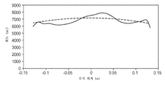
라디언트 이미징(Radiant Imaging)(미국 워싱턴주 두발 소재)으로부터의 모델 번호 PM-1613F-1인 프로메트릭(PROMETRIC) 이미징 광도계를 사용하여 공간 균일성을 측정하였다. 디스플레이의 중앙을 통한 수직 프로파일이 도 6에 도시되어 있다. 측정된 프로파일은 실선으로 도시되어 있고, 요구되는 프로파일은 점선으로 도시되어 있다. 공동을 좁게 하는 것은 중앙에서의 광 추출을 증가시키는 데 효과적이었다. 측정된 데이터는 7880 cd/㎡의 최대치를 가졌으며, 최대치로 나눈 최소치는 80%였다. 바람직한 프로파일은 도 6에서 점선으로 도시되어 있다. 바람직한 프로파일은 측정된 프로파일과 동일한 곡선 아래의 적분 면적을 갖는다. 이러한 바람직한 프로파일의 중앙 휘도는 7170 cd/㎡이다.Spatial uniformity was measured using a PROMETRIC imaging photometer, model number PM-1613F-1 from Radiant Imaging (Dub, Washington). The vertical profile through the center of the display is shown in FIG. 6. The measured profile is shown in solid lines and the required profile is shown in dashed lines. Narrowing the cavity was effective to increase light extraction at the center. The measured data had a maximum of 7880 cd / m 2 and the minimum divided by the maximum was 80%. Preferred profiles are shown in dashed lines in FIG. 6. Preferred profiles have an integrated area under the same curve as the measured profile. The median luminance of this preferred profile is 7170 cd / m 2.
Claims (17)
전방 반사기의 일 단부에 근접하여 있고 5° 내지 90°의 경사각을 갖는 제1 광원; 및
제1 광원으로부터의 광을 중공의 광 공동 내로 지향시키기 위해, 적어도 제1 광원과 후방 반사기 사이에서 연장되는 제1 비대칭 광 시준기(light collimator)를 포함하는 백라이트.A front reflector and a back reflector disposed to form a hollow light cavity;
A first light source proximate one end of the front reflector and having an inclination angle of between 5 ° and 90 °; And
And a first asymmetric light collimator extending between at least the first light source and the back reflector to direct light from the first light source into the hollow light cavity.
제2 광원으로부터의 광을 중공의 광 공동 내로 지향시키기 위해, 제2 광원과 후방 반사기 사이에서 연장되는 제2 비대칭 광 시준기를 추가로 포함하는 백라이트.The apparatus of claim 1, further comprising: a second light source proximate the other end of the front reflector and having an inclination angle of between 5 ° and 90 °; And
And a second asymmetric light collimator extending between the second light source and the back reflector to direct light from the second light source into the hollow light cavity.
Applications Claiming Priority (2)
| Application Number | Priority Date | Filing Date | Title |
|---|---|---|---|
| US5878008P | 2008-06-04 | 2008-06-04 | |
| US61/058,780 | 2008-06-04 |
Publications (1)
| Publication Number | Publication Date |
|---|---|
| KR20110019388A true KR20110019388A (en) | 2011-02-25 |
Family
ID=40909995
Family Applications (1)
| Application Number | Title | Priority Date | Filing Date |
|---|---|---|---|
| KR1020107029480A KR20110019388A (en) | 2008-06-04 | 2009-06-01 | Hollow backlight with tilted light source |
Country Status (7)
| Country | Link |
|---|---|
| US (1) | US8757858B2 (en) |
| EP (1) | EP2297607B1 (en) |
| JP (1) | JP5819723B2 (en) |
| KR (1) | KR20110019388A (en) |
| CN (1) | CN102057319B (en) |
| TW (1) | TW201003248A (en) |
| WO (1) | WO2009149010A1 (en) |
Cited By (8)
| Publication number | Priority date | Publication date | Assignee | Title |
|---|---|---|---|---|
| KR20120123888A (en) * | 2011-05-02 | 2012-11-12 | 엘지이노텍 주식회사 | backlight unit and display apparatus using the same |
| KR20130009344A (en) * | 2011-07-15 | 2013-01-23 | 엘지이노텍 주식회사 | Backlight unit and display apparatus using the same |
| KR20130068653A (en) * | 2011-12-15 | 2013-06-26 | 엘지이노텍 주식회사 | The backlight unit |
| KR20130104560A (en) * | 2012-03-14 | 2013-09-25 | 삼성디스플레이 주식회사 | Backlight assembly and display device comprising the same |
| KR20140028429A (en) * | 2012-08-29 | 2014-03-10 | 엘지이노텍 주식회사 | Light unit and illumination system using the same |
| KR20140066842A (en) * | 2012-11-22 | 2014-06-02 | 삼성디스플레이 주식회사 | Backlight assembly and display device comprising the same |
| KR20170105277A (en) * | 2016-03-09 | 2017-09-19 | 삼성전자주식회사 | Display apparatus |
| US10551030B2 (en) | 2012-03-14 | 2020-02-04 | Samsung Display Co., Ltd. | Display device comprising the same |
Families Citing this family (34)
| Publication number | Priority date | Publication date | Assignee | Title |
|---|---|---|---|---|
| TWI439641B (en) * | 2007-05-20 | 2014-06-01 | 3M Innovative Properties Co | Collimating light injectors for edge-lit backlights |
| TW200916916A (en) * | 2007-05-20 | 2009-04-16 | 3M Innovative Properties Co | White light backlights and the like with efficient utilization of colored LED sources |
| CN101681053B (en) | 2007-05-20 | 2012-03-21 | 3M创新有限公司 | Recycling backlights with semi-specular components |
| US8469575B2 (en) * | 2007-05-20 | 2013-06-25 | 3M Innovative Properties Company | Backlight and display system using same |
| US8523419B2 (en) | 2007-05-20 | 2013-09-03 | 3M Innovative Properties Company | Thin hollow backlights with beneficial design characteristics |
| TWI494655B (en) * | 2008-02-07 | 2015-08-01 | 3M Innovative Properties Co | Hollow backlight device with structured films and display with the same |
| CN101952646B (en) * | 2008-02-22 | 2014-01-29 | 3M创新有限公司 | Backlights having selected output light flux distributions and display systems using same |
| TWI465808B (en) | 2010-11-25 | 2014-12-21 | Lg伊諾特股份有限公司 | Backlight unit and display apparatus using the same |
| JP5989305B2 (en) * | 2011-01-14 | 2016-09-07 | エルジー イノテック カンパニー リミテッド | Backlight unit and display device using the same |
| JP2012204233A (en) * | 2011-03-28 | 2012-10-22 | Panasonic Corp | Light irradiation device and light irradiation therapy/prevention device |
| KR101797599B1 (en) * | 2011-06-30 | 2017-11-15 | 엘지이노텍 주식회사 | backlight unit and display apparatus using the same |
| WO2013024719A1 (en) * | 2011-08-12 | 2013-02-21 | シャープ株式会社 | Illumination device, display device, television receiving device |
| KR101832313B1 (en) * | 2011-08-18 | 2018-04-04 | 엘지이노텍 주식회사 | Display apparatus |
| JP2013052069A (en) * | 2011-09-02 | 2013-03-21 | Panasonic Corp | Light irradiation device and light irradiation therapy/prophylaxis device |
| CN103917901B (en) * | 2011-10-20 | 2018-10-16 | 3M创新有限公司 | Lighting system with slanted transmission spectrum front reflector |
| KR101948140B1 (en) | 2011-12-20 | 2019-02-15 | 엘지이노텍 주식회사 | backlight unit and illumination system using the same |
| KR101943446B1 (en) * | 2011-12-20 | 2019-01-30 | 엘지이노텍 주식회사 | Display apparatus and illumination system |
| KR102024288B1 (en) * | 2012-02-15 | 2019-09-23 | 엘지이노텍 주식회사 | Illumination system using the same |
| CN103218955B (en) * | 2012-02-28 | 2015-10-28 | 天地融科技股份有限公司 | A kind of electronic equipment |
| CN102661529B (en) * | 2012-04-05 | 2014-06-25 | 深圳市华星光电技术有限公司 | Backlight module and liquid crystal display |
| CN102661537B (en) * | 2012-04-16 | 2014-04-23 | 深圳市华星光电技术有限公司 | Backlight module and liquid crystal display |
| KR102034890B1 (en) * | 2012-10-24 | 2019-10-22 | 삼성전자주식회사 | Display apparatus |
| TWI494660B (en) * | 2013-01-08 | 2015-08-01 | Unity Opto Technology Co Ltd | Side light type backlight module |
| WO2014192194A1 (en) * | 2013-05-29 | 2014-12-04 | 株式会社デュエラ | Light box |
| US9316778B2 (en) | 2013-06-21 | 2016-04-19 | Microsoft Technology Licensing, Llc | Hybrid concentrator for a backlight |
| CN104344280A (en) | 2013-07-31 | 2015-02-11 | 扬升照明股份有限公司 | Light source module |
| US9690041B2 (en) | 2013-12-17 | 2017-06-27 | Seoul Semiconductor Co., Ltd. | Air cavity LED backlight unit |
| CN104763919B (en) * | 2014-01-08 | 2017-04-12 | 扬升照明股份有限公司 | Light source module |
| US9046637B1 (en) | 2014-02-25 | 2015-06-02 | 3M Innovative Properties Company | Tubular lighting systems with inner and outer structured surfaces |
| US10161593B2 (en) | 2014-02-25 | 2018-12-25 | 3M Innovative Properties Company | Solid state lighting device with virtual filament(s) |
| US9903995B2 (en) * | 2016-03-03 | 2018-02-27 | Microsoft Technology Licensing, Llc | Flat panel illuminator with concentrator |
| JP6204559B1 (en) * | 2016-06-07 | 2017-09-27 | ルーメンス カンパニー リミテッド | Linear LED module and backlight unit including the same |
| CN107514614B (en) * | 2016-06-16 | 2019-11-29 | 深圳市佰骏工业产品设计有限公司 | Lamps and lanterns |
| FR3065539B1 (en) * | 2017-04-25 | 2019-11-01 | Valeo Comfort And Driving Assistance | HEAD-UP DISPLAY BACKLIGHT DEVICE |
Family Cites Families (203)
| Publication number | Priority date | Publication date | Assignee | Title |
|---|---|---|---|---|
| US5816677A (en) | 1905-03-01 | 1998-10-06 | Canon Kabushiki Kaisha | Backlight device for display apparatus |
| US3610729A (en) | 1969-06-18 | 1971-10-05 | Polaroid Corp | Multilayered light polarizer |
| US3711176A (en) | 1971-01-14 | 1973-01-16 | Dow Chemical Co | Highly reflective thermoplastic bodies for infrared, visible or ultraviolet light |
| US3884606A (en) | 1971-10-01 | 1975-05-20 | Dow Chemical Co | Apparatus for multilayer coextrusion of sheet or film |
| BE789478A (en) | 1971-10-01 | 1973-03-29 | Dow Chemical Co | METHOD AND DEVICE FOR EXTRUDING PLASTICS IN MULTI-LAYER SHEETS |
| US4040727A (en) | 1975-09-10 | 1977-08-09 | Rockwell International Corporation | Transflector |
| US4446305A (en) | 1981-03-02 | 1984-05-01 | Polaroid Corporation | Optical device including birefringent polymer |
| US4456336A (en) | 1981-10-06 | 1984-06-26 | Minnesota Mining And Manufacturing Company | High brightness internal reflector for liquid crystal displays and its method of fabrication |
| US4540623A (en) | 1983-10-14 | 1985-09-10 | The Dow Chemical Company | Coextruded multi-layered articles |
| US4791540A (en) | 1987-05-26 | 1988-12-13 | Minnesota Mining And Manufacturing Company | Light fixture providing normalized output |
| US4964025A (en) | 1988-10-05 | 1990-10-16 | Hewlett-Packard Company | Nonimaging light source |
| WO1991010223A1 (en) | 1989-12-22 | 1991-07-11 | David Sarnoff Research Center, Inc. | Field-sequential display system utilizing a backlit lcd pixel array and method for forming an image |
| US5136479A (en) | 1990-06-19 | 1992-08-04 | E-Systems, Inc. | Device and method for creating an areal light source |
| US5103337A (en) | 1990-07-24 | 1992-04-07 | The Dow Chemical Company | Infrared reflective optical interference film |
| US5126880A (en) | 1990-12-18 | 1992-06-30 | The Dow Chemical Company | Polymeric reflective bodies with multiple layer types |
| US5586013A (en) | 1991-07-19 | 1996-12-17 | Minnesota Mining And Manufacturing Company | Nonimaging optical illumination system |
| US5528720A (en) | 1992-03-23 | 1996-06-18 | Minnesota Mining And Manufacturing Co. | Tapered multilayer luminaire devices |
| KR950704701A (en) | 1992-10-29 | 1995-11-20 | 스티븐 에스. 그레이스 | Formable reflective multilayer body |
| JPH0772815A (en) | 1992-12-15 | 1995-03-17 | Koito Mfg Co Ltd | Liquid crystal display device |
| TW289095B (en) | 1993-01-11 | 1996-10-21 | ||
| US5360659A (en) | 1993-05-24 | 1994-11-01 | The Dow Chemical Company | Two component infrared reflecting film |
| JPH0794008A (en) | 1993-09-24 | 1995-04-07 | Chiyatani Sangyo Kk | Flat lighting device |
| US5381309A (en) | 1993-09-30 | 1995-01-10 | Honeywell Inc. | Backlit display with enhanced viewing properties |
| US5440197A (en) | 1993-10-05 | 1995-08-08 | Tir Technologies, Inc. | Backlighting apparatus for uniformly illuminating a display panel |
| US5828488A (en) | 1993-12-21 | 1998-10-27 | Minnesota Mining And Manufacturing Co. | Reflective polarizer display |
| US5882774A (en) | 1993-12-21 | 1999-03-16 | Minnesota Mining And Manufacturing Company | Optical film |
| WO1996027757A1 (en) | 1995-03-03 | 1996-09-12 | Minnesota Mining And Manufacturing Company | Light directing film having variable height structured surface and light directing article constructed therefrom |
| US5751388A (en) | 1995-04-07 | 1998-05-12 | Honeywell Inc. | High efficiency polarized display |
| JP3187280B2 (en) | 1995-05-23 | 2001-07-11 | シャープ株式会社 | Surface lighting device |
| US6080467A (en) | 1995-06-26 | 2000-06-27 | 3M Innovative Properties Company | High efficiency optical devices |
| JP3935936B2 (en) | 1995-06-26 | 2007-06-27 | スリーエム カンパニー | Transflective display with reflective polarizing transflective reflector |
| DE69629471T2 (en) | 1995-06-26 | 2004-06-09 | Minnesota Mining And Mfg. Co., Saint Paul | BACKLIGHTING DEVICE WITH MULTILAYER FILM REFLECTOR |
| IL122244A0 (en) | 1995-06-26 | 1998-04-05 | Minnesota Mining & Mfg | Multilayer polymer film with additional coatings or layers |
| US6712481B2 (en) | 1995-06-27 | 2004-03-30 | Solid State Opto Limited | Light emitting panel assemblies |
| US5971551A (en) | 1995-07-07 | 1999-10-26 | Arch Development Corporation | Nonimaging optical concentrators and illuminators |
| US5867316A (en) | 1996-02-29 | 1999-02-02 | Minnesota Mining And Manufacturing Company | Multilayer film having a continuous and disperse phase |
| US5825543A (en) | 1996-02-29 | 1998-10-20 | Minnesota Mining And Manufacturing Company | Diffusely reflecting polarizing element including a first birefringent phase and a second phase |
| US6600175B1 (en) | 1996-03-26 | 2003-07-29 | Advanced Technology Materials, Inc. | Solid state white light emitter and display using same |
| JP3409587B2 (en) | 1996-05-14 | 2003-05-26 | オムロン株式会社 | Optical path conversion optical element, image display device, and light projector |
| US5845038A (en) | 1997-01-28 | 1998-12-01 | Minnesota Mining And Manufacturing Company | Optical fiber illumination system |
| US6280063B1 (en) | 1997-05-09 | 2001-08-28 | 3M Innovative Properties Company | Brightness enhancement article |
| JPH1172625A (en) * | 1997-06-30 | 1999-03-16 | Toshiba Lighting & Technol Corp | Back light and liquid crystal display device using it |
| US5976686A (en) | 1997-10-24 | 1999-11-02 | 3M Innovative Properties Company | Diffuse reflective articles |
| US6531230B1 (en) | 1998-01-13 | 2003-03-11 | 3M Innovative Properties Company | Color shifting film |
| US6808658B2 (en) | 1998-01-13 | 2004-10-26 | 3M Innovative Properties Company | Method for making texture multilayer optical films |
| US6157490A (en) | 1998-01-13 | 2000-12-05 | 3M Innovative Properties Company | Optical film with sharpened bandedge |
| US6157486A (en) | 1998-01-13 | 2000-12-05 | 3M Innovative Properties Company | Retroreflective dichroic reflector |
| DE69939647D1 (en) | 1998-02-18 | 2008-11-13 | Minnesota Mining & Mfg | OPTICAL FILM |
| US6282821B1 (en) | 1998-06-25 | 2001-09-04 | 3M Innovative Properties Company | Low-loss face diffuser films for backlit signage and methods for using same |
| US6752505B2 (en) | 1999-02-23 | 2004-06-22 | Solid State Opto Limited | Light redirecting films and film systems |
| AU750659B2 (en) | 1999-02-24 | 2002-07-25 | 3M Innovative Properties Company | Illumination device for producing predetermined intensity patterns |
| US6267492B1 (en) | 1999-04-15 | 2001-07-31 | 3M Innovative Properties Company | Illumination device with side emitting light guide |
| JP3434465B2 (en) | 1999-04-22 | 2003-08-11 | 三菱電機株式会社 | Backlight for liquid crystal display |
| DE19961491B4 (en) | 1999-05-25 | 2005-08-04 | Siteco Beleuchtungstechnik Gmbh | Interior light with hollow fiber optic cable |
| US6122103A (en) | 1999-06-22 | 2000-09-19 | Moxtech | Broadband wire grid polarizer for the visible spectrum |
| DE50014438D1 (en) | 1999-07-23 | 2007-08-09 | Siteco Beleuchtungstech Gmbh | Compact luminaire with hollow fiber optic cable |
| KR100679094B1 (en) | 1999-10-08 | 2007-02-05 | 엘지.필립스 엘시디 주식회사 | BackLight Unit |
| EP1236009A2 (en) | 1999-11-30 | 2002-09-04 | Reflexite Corporation | Luminaire system |
| US6738349B1 (en) | 2000-03-01 | 2004-05-18 | Tektronix, Inc. | Non-intrusive measurement of end-to-end network properties |
| US6893135B2 (en) | 2000-03-16 | 2005-05-17 | 3M Innovative Properties Company | Light guides suitable for illuminated displays |
| JP3301752B2 (en) | 2000-03-31 | 2002-07-15 | 三菱電機株式会社 | Front light, reflective liquid crystal display device and portable information terminal |
| US6975455B1 (en) | 2000-04-18 | 2005-12-13 | 3M Innovative Properties Company | Transflective layer for displays |
| NZ522738A (en) | 2000-04-25 | 2004-05-28 | Honeywell Int Inc | Hollow cavity light guide for the distribution of collimated light to a liquid crystal display |
| JP2002008425A (en) * | 2000-06-21 | 2002-01-11 | Fujitsu Ltd | Back light unit |
| JP4288553B2 (en) | 2000-07-25 | 2009-07-01 | 富士フイルム株式会社 | Camera strobe device |
| US6809892B2 (en) * | 2000-07-26 | 2004-10-26 | 3M Innovative Properties Company | Hollow surface illuminator |
| JP4023079B2 (en) | 2000-08-31 | 2007-12-19 | 株式会社日立製作所 | Planar illumination device and display device including the same |
| US6673425B1 (en) | 2000-10-27 | 2004-01-06 | 3M Innovative Properties Company | Method and materials for preventing warping in optical films |
| US6888529B2 (en) | 2000-12-12 | 2005-05-03 | Koninklijke Philips Electronics N.V. | Control and drive circuit arrangement for illumination performance enhancement with LED light sources |
| US6917399B2 (en) | 2001-02-22 | 2005-07-12 | 3M Innovative Properties Company | Optical bodies containing cholesteric liquid crystal material and methods of manufacture |
| CN1462354A (en) | 2001-05-08 | 2003-12-17 | 荷兰鲁米勒德斯照明有限公司 | Illumination system and display device |
| JP2002350846A (en) | 2001-05-22 | 2002-12-04 | Yazaki Corp | Led back light |
| ATE475168T1 (en) | 2001-06-07 | 2010-08-15 | Genoa Color Technologies Ltd | SYSTEM AND METHOD FOR DATA CONVERSION FOR ADVERTISEMENTS WITH A LARGE STAGE LADDER |
| JP2003029720A (en) | 2001-07-16 | 2003-01-31 | Fujitsu Ltd | Display device |
| KR100864738B1 (en) | 2001-08-27 | 2008-10-22 | 코닌클리즈케 필립스 일렉트로닉스 엔.브이. | Light panel with enlarged viewing window |
| US6663262B2 (en) | 2001-09-10 | 2003-12-16 | 3M Innovative Properties Company | Backlighting transmissive displays |
| GB0123813D0 (en) | 2001-10-03 | 2001-11-21 | 3M Innovative Properties Co | Light-guide lights suitable for use in illuminated displays |
| GB0123815D0 (en) | 2001-10-03 | 2001-11-21 | 3M Innovative Properties Co | Light-guide lights providing a substantially monochromatic beam |
| CA2465523A1 (en) * | 2001-11-02 | 2003-05-15 | Honeywell International Inc. | Hollow wedge shape light guide for back illumination |
| EP2423717A3 (en) | 2001-12-14 | 2012-12-12 | QUALCOMM MEMS Technologies, Inc. | Uniform illumination system |
| US6937303B2 (en) | 2001-12-18 | 2005-08-30 | Samsung Electronics Co., Ltd. | Transmissive and reflective type liquid crystal display |
| JP2003223982A (en) | 2002-01-31 | 2003-08-08 | Matsushita Electric Ind Co Ltd | High frequency heating device |
| US6973827B2 (en) | 2002-03-20 | 2005-12-13 | Mitsui Mining & Smelting Co., Ltd. | Flow rate measuring method and flowmeter, flow rate measuring section package used for them and flow rate measuring unit using them, and piping leakage inspection device using flowmeter |
| US6679621B2 (en) * | 2002-06-24 | 2004-01-20 | Lumileds Lighting U.S., Llc | Side emitting LED and lens |
| JP2004031180A (en) | 2002-06-27 | 2004-01-29 | Kawaguchiko Seimitsu Co Ltd | Backlight device |
| JP2004111357A (en) | 2002-07-09 | 2004-04-08 | Topcon Corp | Light source device |
| JP2004055430A (en) | 2002-07-23 | 2004-02-19 | Kawaguchiko Seimitsu Co Ltd | Back light system |
| JP4177049B2 (en) | 2002-08-28 | 2008-11-05 | シャープ株式会社 | Surface mount type side light emitting diode and manufacturing method thereof |
| US7460196B2 (en) | 2002-09-25 | 2008-12-02 | Lg Displays Co., Ltd. | Backlight device for liquid crystal display and method of fabricating the same |
| JP4153776B2 (en) | 2002-11-07 | 2008-09-24 | 三菱電機株式会社 | Planar light source device and liquid crystal display device using the same |
| JP2004171947A (en) | 2002-11-20 | 2004-06-17 | Harison Toshiba Lighting Corp | Backlight device |
| JP4091414B2 (en) | 2002-12-18 | 2008-05-28 | 三菱電機株式会社 | Planar light source device, display device, and liquid crystal display device |
| US20040219338A1 (en) | 2003-05-01 | 2004-11-04 | Hebrink Timothy J. | Materials, configurations, and methods for reducing warpage in optical films |
| US6814456B1 (en) | 2003-05-15 | 2004-11-09 | Toppoly Optoelectronics Corp. | Back light module |
| JP2004342429A (en) | 2003-05-15 | 2004-12-02 | Advanced Display Inc | Planar light source device, and liquid crystal display equipped with same |
| US6846089B2 (en) | 2003-05-16 | 2005-01-25 | 3M Innovative Properties Company | Method for stacking surface structured optical films |
| US6974229B2 (en) | 2003-05-21 | 2005-12-13 | Lumileds Lighting U.S., Llc | Devices for creating brightness profiles |
| WO2004111532A1 (en) * | 2003-06-16 | 2004-12-23 | Advanced Display Inc. | Planar light source device and display device using the same |
| US6905212B2 (en) | 2003-07-02 | 2005-06-14 | Hewlett-Packard Development Company, L.P. | Varying light beam for a display system |
| TW594264B (en) | 2003-07-09 | 2004-06-21 | Chunghwa Picture Tubes Ltd | A light-projecting device for a backlight module in a flat panel display device |
| TWI264511B (en) | 2003-07-11 | 2006-10-21 | Hon Hai Prec Ind Co Ltd | Light source system and backlight module using the same |
| JP2004071576A (en) | 2003-08-18 | 2004-03-04 | Minnesota Mining & Mfg Co <3M> | Surface light emitting device |
| US7282272B2 (en) | 2003-09-12 | 2007-10-16 | 3M Innovative Properties Company | Polymerizable compositions comprising nanoparticles |
| JP2005093147A (en) | 2003-09-16 | 2005-04-07 | Sharp Corp | Lighting system and display device equipped with the same, and portable electronic equipment |
| US7114839B2 (en) | 2003-10-06 | 2006-10-03 | Chia Shin Kuo | Light-inverse type guidelight plate |
| JP2005173546A (en) | 2003-11-18 | 2005-06-30 | Toray Ind Inc | Light reflective film and surface light source using the same |
| US7052168B2 (en) | 2003-12-17 | 2006-05-30 | 3M Innovative Properties Company | Illumination device |
| US7223005B2 (en) * | 2003-12-23 | 2007-05-29 | Lamb David J | Hybrid lightguide backlight |
| US7303322B2 (en) | 2003-12-23 | 2007-12-04 | 3M Innovative Properties Company | Multiple lightguide backlight |
| JP2005190861A (en) | 2003-12-26 | 2005-07-14 | Harison Toshiba Lighting Corp | Backlight |
| US7009343B2 (en) | 2004-03-11 | 2006-03-07 | Kevin Len Li Lim | System and method for producing white light using LEDs |
| JP2005292546A (en) | 2004-04-01 | 2005-10-20 | Mitsubishi Electric Corp | Liquid crystal display device of low power consumption |
| KR100576865B1 (en) | 2004-05-03 | 2006-05-10 | 삼성전기주식회사 | Light emitting diode array module and backlight unit using the same |
| JP2005327682A (en) | 2004-05-17 | 2005-11-24 | Sony Corp | Backlight device and liquid crystal display device |
| JP4590283B2 (en) | 2004-05-21 | 2010-12-01 | シャープ株式会社 | Backlight unit and liquid crystal display device including the same |
| TWI310471B (en) | 2004-05-25 | 2009-06-01 | Au Optronics Corp | Backlight module equipped with brightness convergence function |
| KR100586966B1 (en) | 2004-05-27 | 2006-06-08 | 삼성전기주식회사 | Back light module |
| US7997771B2 (en) | 2004-06-01 | 2011-08-16 | 3M Innovative Properties Company | LED array systems |
| TWI233220B (en) | 2004-06-18 | 2005-05-21 | Chi Mei Optoelectronics Corp | Light emitting diode package |
| KR20050121076A (en) | 2004-06-21 | 2005-12-26 | 삼성전자주식회사 | Back light assembly and display device having the same |
| KR20060000544A (en) | 2004-06-29 | 2006-01-06 | 삼성전자주식회사 | Back light for display device, light source for display device, and light emitting diode using therefor |
| US7213958B2 (en) | 2004-06-30 | 2007-05-08 | 3M Innovative Properties Company | Phosphor based illumination system having light guide and an interference reflector |
| EP1640756A1 (en) | 2004-09-27 | 2006-03-29 | Barco N.V. | Methods and systems for illuminating |
| US7436469B2 (en) | 2004-10-15 | 2008-10-14 | 3M Innovative Properties Company | Composite diffuser plates and direct-lit liquid crystal displays using same |
| US7446827B2 (en) | 2004-10-15 | 2008-11-04 | 3M Innovative Properties Company | Direct-lit liquid crystal displays with laminated diffuser plates |
| US7329982B2 (en) | 2004-10-29 | 2008-02-12 | 3M Innovative Properties Company | LED package with non-bonded optical element |
| WO2006052834A2 (en) | 2004-11-05 | 2006-05-18 | Optical Research Associates | Methods for manipulating light extraction from a light |
| US20060103777A1 (en) | 2004-11-15 | 2006-05-18 | 3M Innovative Properties Company | Optical film having a structured surface with rectangular based prisms |
| US7745814B2 (en) | 2004-12-09 | 2010-06-29 | 3M Innovative Properties Company | Polychromatic LED's and related semiconductor devices |
| US20060131601A1 (en) | 2004-12-21 | 2006-06-22 | Ouderkirk Andrew J | Illumination assembly and method of making same |
| US7285802B2 (en) | 2004-12-21 | 2007-10-23 | 3M Innovative Properties Company | Illumination assembly and method of making same |
| US7296916B2 (en) | 2004-12-21 | 2007-11-20 | 3M Innovative Properties Company | Illumination assembly and method of making same |
| US7220026B2 (en) | 2004-12-30 | 2007-05-22 | 3M Innovative Properties Company | Optical film having a structured surface with offset prismatic structures |
| US7320538B2 (en) | 2004-12-30 | 2008-01-22 | 3M Innovative Properties Company | Optical film having a structured surface with concave pyramid-shaped structures |
| US7416309B2 (en) | 2004-12-30 | 2008-08-26 | 3M Innovative Properties Company | Optical film having a surface with rounded structures |
| DE202005005306U1 (en) | 2005-04-04 | 2006-08-10 | Aeg Gesellschaft für Moderne Informationssysteme mbH | Transreflective LCD device, has diffusing panel arranged behind LCD-unit, LED arranged in border area surrounding panel and unit, and light reflecting device having reflector concavely curved from LED to reflect light to panel/unit |
| EP1696260B1 (en) * | 2005-02-08 | 2013-09-25 | BMG Gesellschaft für moderne Informationssysteme mbH | Liquid crystal display and liquid crystal display system comprising a plurality of such liquid crystal displays |
| JP2006221922A (en) | 2005-02-09 | 2006-08-24 | Mitsubishi Rayon Co Ltd | Led planar light source device |
| US20060187650A1 (en) | 2005-02-24 | 2006-08-24 | 3M Innovative Properties Company | Direct lit backlight with light recycling and source polarizers |
| JP4431070B2 (en) | 2005-02-28 | 2010-03-10 | シャープ株式会社 | Surface illumination device and liquid crystal display device including the same |
| US7356229B2 (en) | 2005-02-28 | 2008-04-08 | 3M Innovative Properties Company | Reflective polarizers containing polymer fibers |
| JP4852695B2 (en) * | 2005-03-17 | 2012-01-11 | 国立大学法人東北大学 | Liquid crystal display and backlight unit |
| JP4430571B2 (en) | 2005-03-25 | 2010-03-10 | 三菱レイヨン株式会社 | LED surface light source device |
| JP2006269364A (en) | 2005-03-25 | 2006-10-05 | Mitsubishi Rayon Co Ltd | Led surface light source device |
| US20060221610A1 (en) | 2005-04-01 | 2006-10-05 | Chew Tong F | Light-emitting apparatus having a plurality of overlapping panels forming recesses from which light is emitted |
| US20060250707A1 (en) | 2005-05-05 | 2006-11-09 | 3M Innovative Properties Company | Optical film having a surface with rounded pyramidal structures |
| US20060257678A1 (en) | 2005-05-10 | 2006-11-16 | Benson Olester Jr | Fiber reinforced optical films |
| KR100774061B1 (en) | 2005-05-17 | 2007-11-06 | 엔이씨 엘씨디 테크놀로지스, 엘티디. | Backlight and liquid crystal display device |
| US7220036B2 (en) | 2005-05-20 | 2007-05-22 | 3M Innovative Properties Company | Thin direct-lit backlight for LCD display |
| US7591094B2 (en) | 2005-05-31 | 2009-09-22 | The University Of British Columbia | Perforated multi-layer optical film luminaire |
| US7196483B2 (en) | 2005-06-16 | 2007-03-27 | Au Optronics Corporation | Balanced circuit for multi-LED driver |
| US8023065B2 (en) | 2005-06-24 | 2011-09-20 | 3M Innovative Properties Company | Optical element for lateral light spreading in edge-lit displays and system using same |
| US7903194B2 (en) | 2005-06-24 | 2011-03-08 | 3M Innovative Properties Company | Optical element for lateral light spreading in back-lit displays and system using same |
| JP4935004B2 (en) | 2005-07-01 | 2012-05-23 | ソニー株式会社 | Display device |
| US20070024994A1 (en) | 2005-07-29 | 2007-02-01 | 3M Innovative Properties Company | Structured optical film with interspersed pyramidal structures |
| TWI464494B (en) | 2005-08-27 | 2014-12-11 | 3M Innovative Properties Co | Illumination assembly and system |
| US7537374B2 (en) | 2005-08-27 | 2009-05-26 | 3M Innovative Properties Company | Edge-lit backlight having light recycling cavity with concave transflector |
| US20070047228A1 (en) | 2005-08-27 | 2007-03-01 | 3M Innovative Properties Company | Methods of forming direct-lit backlights having light recycling cavity with concave transflector |
| US7473019B2 (en) * | 2005-09-29 | 2009-01-06 | Osram Opto Semiconductors Gmbh | Lighting apparatus |
| US7438442B2 (en) | 2005-10-12 | 2008-10-21 | Lg Display Co., Ltd. | Light emitting package, backlight unit and liquid crystal display device including the same |
| TWI331694B (en) | 2005-10-20 | 2010-10-11 | Ind Tech Res Inst | Back-lighted structure |
| KR20080063786A (en) * | 2005-10-28 | 2008-07-07 | 타키론 가부시기가이샤 | Surface-emitting device and light-emitting method for surface-emitting device |
| US20070147037A1 (en) | 2005-12-22 | 2007-06-28 | Dynascan Technology Corp. | Super slim LCD backlight device using uniforming chamber |
| US20070153384A1 (en) | 2005-12-30 | 2007-07-05 | Ouderkirk Andrew J | Reinforced reflective polarizer films |
| US20070153162A1 (en) | 2005-12-30 | 2007-07-05 | Wright Robin E | Reinforced reflective polarizer films |
| TW200728851A (en) | 2006-01-20 | 2007-08-01 | Hon Hai Prec Ind Co Ltd | Backlight module |
| CN100468170C (en) | 2006-02-10 | 2009-03-11 | 鸿富锦精密工业(深圳)有限公司 | Back light system |
| CN100462811C (en) * | 2006-02-10 | 2009-02-18 | 鸿富锦精密工业(深圳)有限公司 | Box-type light source mold train and back light system |
| TWI294023B (en) * | 2006-03-17 | 2008-03-01 | Ind Tech Res Inst | Reflective illumination device |
| KR20070096457A (en) | 2006-03-24 | 2007-10-02 | 엘지전자 주식회사 | Planar light source using a light pipe, back light unit and liquid crystal display having the same |
| US20070258241A1 (en) | 2006-05-02 | 2007-11-08 | 3M Innovative Properties Company | Led package with non-bonded converging optical element |
| US20070257270A1 (en) | 2006-05-02 | 2007-11-08 | 3M Innovative Properties Company | Led package with wedge-shaped optical element |
| US7390117B2 (en) | 2006-05-02 | 2008-06-24 | 3M Innovative Properties Company | LED package with compound converging optical element |
| US7525126B2 (en) | 2006-05-02 | 2009-04-28 | 3M Innovative Properties Company | LED package with converging optical element |
| US7740387B2 (en) | 2006-05-24 | 2010-06-22 | 3M Innovative Properties Company | Backlight wedge with side mounted light source |
| US7607814B2 (en) | 2006-05-24 | 2009-10-27 | 3M Innovative Properties Company | Backlight with symmetric wedge shaped light guide input portion with specular reflective surfaces |
| US7317182B2 (en) | 2006-05-24 | 2008-01-08 | 3M Innovative Properties Company | Backlight wedge with encapsulated light source |
| US7660509B2 (en) | 2006-05-24 | 2010-02-09 | 3M Innovative Properties Company | Backlight asymmetric light input wedge |
| US20080002256A1 (en) | 2006-06-30 | 2008-01-03 | 3M Innovative Properties Company | Optical article including a beaded layer |
| TWM317024U (en) | 2006-07-25 | 2007-08-11 | Longtech Systems Corp | Brightness improved structure of lateral backlight for LCD |
| JP4966701B2 (en) | 2006-08-03 | 2012-07-04 | ハリソン東芝ライティング株式会社 | Hollow surface lighting device |
| US7905650B2 (en) | 2006-08-25 | 2011-03-15 | 3M Innovative Properties Company | Backlight suitable for display devices |
| US7773834B2 (en) | 2006-08-30 | 2010-08-10 | 3M Innovative Properties Company | Multilayer polarizing fibers and polarizers using same |
| US20080057277A1 (en) | 2006-08-30 | 2008-03-06 | 3M Innovative Properties Company | Polymer fiber polarizers |
| JP4134222B2 (en) | 2006-09-21 | 2008-08-20 | シャープ株式会社 | Backlight device |
| US7481563B2 (en) | 2006-09-21 | 2009-01-27 | 3M Innovative Properties Company | LED backlight |
| EP2084573B1 (en) | 2006-10-26 | 2016-03-16 | Koninklijke Philips N.V. | Illumination system and display device |
| US7604381B2 (en) | 2007-04-16 | 2009-10-20 | 3M Innovative Properties Company | Optical article and method of making |
| TWI439641B (en) | 2007-05-20 | 2014-06-01 | 3M Innovative Properties Co | Collimating light injectors for edge-lit backlights |
| US8469575B2 (en) | 2007-05-20 | 2013-06-25 | 3M Innovative Properties Company | Backlight and display system using same |
| US8523419B2 (en) | 2007-05-20 | 2013-09-03 | 3M Innovative Properties Company | Thin hollow backlights with beneficial design characteristics |
| TW200916916A (en) | 2007-05-20 | 2009-04-16 | 3M Innovative Properties Co | White light backlights and the like with efficient utilization of colored LED sources |
| CN101681053B (en) * | 2007-05-20 | 2012-03-21 | 3M创新有限公司 | Recycling backlights with semi-specular components |
| US7513634B2 (en) | 2007-05-21 | 2009-04-07 | National Tsing Hua University | Structure of planar illuminator |
| TWI422782B (en) | 2007-05-29 | 2014-01-11 | 皇家飛利浦電子股份有限公司 | Illumination system, luminaire and backlighting unit |
| EP2171530A4 (en) * | 2007-07-03 | 2010-10-20 | 3M Innovative Properties Co | Optically transmissive composite film frame |
| TWI494655B (en) * | 2008-02-07 | 2015-08-01 | 3M Innovative Properties Co | Hollow backlight device with structured films and display with the same |
| CN101952646B (en) | 2008-02-22 | 2014-01-29 | 3M创新有限公司 | Backlights having selected output light flux distributions and display systems using same |
| US8608362B2 (en) | 2008-06-13 | 2013-12-17 | 3M Innovative Properties Company | Collimating light engine |
| EP2350737B1 (en) * | 2008-10-27 | 2014-11-26 | 3M Innovative Properties Company | Semispecular hollow backlight with gradient extraction |
| US8382324B2 (en) * | 2010-04-29 | 2013-02-26 | Southern Taiwan University | Radiation structure without light guiding board |
| TWI465808B (en) * | 2010-11-25 | 2014-12-21 | Lg伊諾特股份有限公司 | Backlight unit and display apparatus using the same |
| KR101824039B1 (en) * | 2011-07-29 | 2018-01-31 | 엘지이노텍 주식회사 | display apparatus |
-
2009
- 2009-06-01 WO PCT/US2009/045832 patent/WO2009149010A1/en active Application Filing
- 2009-06-01 CN CN200980120873.3A patent/CN102057319B/en not_active Expired - Fee Related
- 2009-06-01 EP EP09759171.3A patent/EP2297607B1/en not_active Not-in-force
- 2009-06-01 JP JP2011512563A patent/JP5819723B2/en not_active Expired - Fee Related
- 2009-06-01 KR KR1020107029480A patent/KR20110019388A/en not_active Application Discontinuation
- 2009-06-01 US US12/995,368 patent/US8757858B2/en not_active Expired - Fee Related
- 2009-06-03 TW TW098118441A patent/TW201003248A/en unknown
Cited By (9)
| Publication number | Priority date | Publication date | Assignee | Title |
|---|---|---|---|---|
| KR20120123888A (en) * | 2011-05-02 | 2012-11-12 | 엘지이노텍 주식회사 | backlight unit and display apparatus using the same |
| KR101880130B1 (en) * | 2011-05-02 | 2018-07-19 | 엘지이노텍 주식회사 | backlight unit and display apparatus using the same |
| KR20130009344A (en) * | 2011-07-15 | 2013-01-23 | 엘지이노텍 주식회사 | Backlight unit and display apparatus using the same |
| KR20130068653A (en) * | 2011-12-15 | 2013-06-26 | 엘지이노텍 주식회사 | The backlight unit |
| KR20130104560A (en) * | 2012-03-14 | 2013-09-25 | 삼성디스플레이 주식회사 | Backlight assembly and display device comprising the same |
| US10551030B2 (en) | 2012-03-14 | 2020-02-04 | Samsung Display Co., Ltd. | Display device comprising the same |
| KR20140028429A (en) * | 2012-08-29 | 2014-03-10 | 엘지이노텍 주식회사 | Light unit and illumination system using the same |
| KR20140066842A (en) * | 2012-11-22 | 2014-06-02 | 삼성디스플레이 주식회사 | Backlight assembly and display device comprising the same |
| KR20170105277A (en) * | 2016-03-09 | 2017-09-19 | 삼성전자주식회사 | Display apparatus |
Also Published As
| Publication number | Publication date |
|---|---|
| TW201003248A (en) | 2010-01-16 |
| CN102057319B (en) | 2014-02-26 |
| WO2009149010A1 (en) | 2009-12-10 |
| US8757858B2 (en) | 2014-06-24 |
| EP2297607B1 (en) | 2014-04-23 |
| US20110134659A1 (en) | 2011-06-09 |
| CN102057319A (en) | 2011-05-11 |
| JP2011523177A (en) | 2011-08-04 |
| JP5819723B2 (en) | 2015-11-24 |
| EP2297607A1 (en) | 2011-03-23 |
Similar Documents
| Publication | Publication Date | Title |
|---|---|---|
| US8757858B2 (en) | Hollow backlight with tilted light source | |
| JP5702151B2 (en) | Hollow backlight with structured film | |
| JP3059883B2 (en) | Assembly for backlighting using a microprism having a multiple reflection illumination system | |
| JP4487629B2 (en) | Surface illumination device and liquid crystal display device using the same | |
| US7220036B2 (en) | Thin direct-lit backlight for LCD display | |
| US7416309B2 (en) | Optical film having a surface with rounded structures | |
| JP2008527632A (en) | Optical film having structured surface with concave pyramid-like structure | |
| US20120026722A1 (en) | Light guide plates and backlight module | |
| JP2008527408A (en) | Optical film having structured surface with staggered prismatic structure | |
| KR20090085059A (en) | Back-lit displays with high illumination uniformity | |
| KR20090085099A (en) | Back-lit displays with high illumination uniformity | |
| KR20070028385A (en) | Diffusive reflector film for liquid crystal display backlight | |
| EP2160644A2 (en) | Semi-specular components in hollow cavity light recycling backlights | |
| TWI428639B (en) | Diffuser plate, backlight unit and liquid crystal display having the same | |
| TW200937085A (en) | Backlight unit | |
| JP2000147264A (en) | Light control sheet and surface light source device using the same | |
| US20090316430A1 (en) | Backlight module | |
| US20110032449A1 (en) | Perforated backlight | |
| JP5672833B2 (en) | Illumination unit and display device using the same | |
| JP2000121838A (en) | Surface light source device and liquid crystal display |
Legal Events
| Date | Code | Title | Description |
|---|---|---|---|
| A201 | Request for examination | ||
| E902 | Notification of reason for refusal | ||
| E601 | Decision to refuse application |