KR20100137433A - Digital pens and a method for digital recording of information - Google Patents
Digital pens and a method for digital recording of information Download PDFInfo
- Publication number
- KR20100137433A KR20100137433A KR1020107019085A KR20107019085A KR20100137433A KR 20100137433 A KR20100137433 A KR 20100137433A KR 1020107019085 A KR1020107019085 A KR 1020107019085A KR 20107019085 A KR20107019085 A KR 20107019085A KR 20100137433 A KR20100137433 A KR 20100137433A
- Authority
- KR
- South Korea
- Prior art keywords
- digital pen
- image
- pen
- digital
- recording information
- Prior art date
Links
Images


Classifications
-
- G—PHYSICS
- G06—COMPUTING; CALCULATING OR COUNTING
- G06F—ELECTRIC DIGITAL DATA PROCESSING
- G06F3/00—Input arrangements for transferring data to be processed into a form capable of being handled by the computer; Output arrangements for transferring data from processing unit to output unit, e.g. interface arrangements
- G06F3/01—Input arrangements or combined input and output arrangements for interaction between user and computer
- G06F3/03—Arrangements for converting the position or the displacement of a member into a coded form
- G06F3/033—Pointing devices displaced or positioned by the user, e.g. mice, trackballs, pens or joysticks; Accessories therefor
- G06F3/0354—Pointing devices displaced or positioned by the user, e.g. mice, trackballs, pens or joysticks; Accessories therefor with detection of 2D relative movements between the device, or an operating part thereof, and a plane or surface, e.g. 2D mice, trackballs, pens or pucks
- G06F3/03545—Pens or stylus
-
- G—PHYSICS
- G06—COMPUTING; CALCULATING OR COUNTING
- G06V—IMAGE OR VIDEO RECOGNITION OR UNDERSTANDING
- G06V10/00—Arrangements for image or video recognition or understanding
- G06V10/10—Image acquisition
- G06V10/12—Details of acquisition arrangements; Constructional details thereof
- G06V10/14—Optical characteristics of the device performing the acquisition or on the illumination arrangements
- G06V10/145—Illumination specially adapted for pattern recognition, e.g. using gratings
-
- G—PHYSICS
- G06—COMPUTING; CALCULATING OR COUNTING
- G06V—IMAGE OR VIDEO RECOGNITION OR UNDERSTANDING
- G06V30/00—Character recognition; Recognising digital ink; Document-oriented image-based pattern recognition
- G06V30/10—Character recognition
- G06V30/14—Image acquisition
- G06V30/142—Image acquisition using hand-held instruments; Constructional details of the instruments
- G06V30/1423—Image acquisition using hand-held instruments; Constructional details of the instruments the instrument generating sequences of position coordinates corresponding to handwriting
-
- G—PHYSICS
- G06—COMPUTING; CALCULATING OR COUNTING
- G06V—IMAGE OR VIDEO RECOGNITION OR UNDERSTANDING
- G06V10/00—Arrangements for image or video recognition or understanding
- G06V10/10—Image acquisition
- G06V10/19—Image acquisition by sensing codes defining pattern positions
Landscapes
- Engineering & Computer Science (AREA)
- Theoretical Computer Science (AREA)
- Physics & Mathematics (AREA)
- General Physics & Mathematics (AREA)
- Computer Vision & Pattern Recognition (AREA)
- Multimedia (AREA)
- General Engineering & Computer Science (AREA)
- Human Computer Interaction (AREA)
- Artificial Intelligence (AREA)
- Position Input By Displaying (AREA)
- Image Input (AREA)
Abstract
이미지가 하나 이상의 센서에 의해 캡쳐될 때 패턴화된 표면을 조명하기 위한 하나 이상의 광원 및 패턴화된 표면의 이미지를 캡쳐하기 위한 하나 이상의 센서를 구비한 광학 시스템이 디지털 펜에 제공된다. 디지털 펜이 광택 표면 상에서 이용될 때 거울같이 반사된 광에 의해 센서가 가끔 블라인드 되는(blinded) 문제점을 해결하기 위해, 광학 시스템이 적어도 두 개의 이미지 캡쳐 상태 사이에서 조정 가능하고, 이 경우 이미지는 적어도 하나의 센서 및 적어도 하나의 광원의 상이한 기하학적 배열로 캡쳐된다. 보충적으로 또는 대안적으로, 디지털 펜은 제 1 편광 방향을 가진 선형적으로 편광된(polarized) 광을 가진 패턴화된 표면을 조명할 수 있고, 추가적으로 이미지 센서의 전방에서 선형 편광기가 제공될 수 있으며, 이러한 편광기는 두 개의 상이한 편광 방향을 가지며 거울같이 반사된 광이 센서에 도달하는 것을 방지한다.An optical system is provided in a digital pen having one or more light sources for illuminating a patterned surface and one or more sensors for capturing an image of the patterned surface when the image is captured by one or more sensors. To solve the problem that the sensor is sometimes blinded by mirror-reflected light when the digital pen is used on a glossy surface, the optical system is adjustable between at least two image capture states, in which the image is at least Captured with different geometries of one sensor and at least one light source. Additionally or alternatively, the digital pen can illuminate a patterned surface with linearly polarized light with a first polarization direction, and additionally a linear polarizer can be provided in front of the image sensor, This polarizer has two different polarization directions and prevents specularly reflected light from reaching the sensor.
Description
본 발명은 디지털 펜 및 패턴화된 표면을 이용하여 정보의 디지털 기록을 위한 방법에 관한 것이다.
The present invention relates to a method for digital recording of information using a digital pen and a patterned surface.
펜 스트로크가 형성되는 동안 표면의 이미지를 캡쳐하는 디지털 펜에 의해 표면 상에 형성된 펜 스트로크를 디지털적으로 기록하는 것이 알려져 있다. 펜 스트로크의 디지털 기록을 가능하게 하기 위해, 표면에는 캡쳐된 이미지의 내용을 이용하여 표면 상에 디지털 펜의 상대 위치 또는 절대 위치를 결정하는 것을 가능하게 하는 패턴이 제공된다.It is known to digitally record a pen stroke formed on the surface by a digital pen that captures an image of the surface while the pen stroke is formed. To enable digital recording of pen strokes, the surface is provided with a pattern that makes it possible to determine the relative or absolute position of the digital pen on the surface using the content of the captured image.
절대 위치 코딩 패턴 상에서 작동하는 디지털 펜의 일례는 WO 01/26032 A1호에서 개시되어 있다. 이 펜은 표면을 조명하기 위한 발광 다이오드, 표면을 이미지하기 위한 광학 센서 그리고 이미지로부터 위치를 해독하기 위한 프로세서를 포함한다.An example of a digital pen operating on an absolute position coding pattern is disclosed in WO 01/26032 A1. The pen includes a light emitting diode to illuminate the surface, an optical sensor to image the surface, and a processor to decode the position from the image.
디지털 펜이 코팅된 페이퍼 또는 화이트보드와 같은 광택 표면 또는 빛나는 표면 상에서 이용될 때 해독 문제점들이 때때로 일어날 수 있는데, 왜냐하면 일정한 이미지에서 밝기가 너무 높아서 패턴을 분별하는 것이 어렵거나 심지어는 불가능하기 때문이다.
Decryption problems can sometimes occur when the digital pen is used on glossy or shiny surfaces, such as coated paper or whiteboard, because in certain images the brightness is too high to discern patterns that are difficult or even impossible.
상기 언급된 해독 문제점은 청구항 제 1 항에 따른 디지털 펜, 청구항 제 9 항에 따른 디지털 펜, 그리고 청구항 제 12 항에 따른 방법에 의해 적어도 부분적으로 해결될 수 있다.The above-mentioned decoding problem can be solved at least in part by the digital pen according to claim 1, the digital pen according to claim 9, and the method according to claim 12.
본 발명의 제 1 태양에 따르면, 패턴화된 표면을 이용하여 정보를 디지털 기록하기 위한 디지털 펜이 제공되고, 이는 디지털 펜이 패턴화된 표면 상에서 작동하는 동안 패턴화된 표면의 이미지를 캡쳐하기 위한 하나 이상의 센서 및 하나 이상의 센서에 의해 이미지가 캡쳐될 때 패턴화된 표면을 조명하기 위한 하나 이상의 광원을 구비한 광학 시스템을 포함하고, 이 경우 광학 시스템은 하나 이상의 센서 및 하나 이상의 광원의 상이한 기하학적 배열로 이미지가 캡쳐되는 둘 이상의 이미지 캡쳐 상태 사이에서 조정 가능하다.According to a first aspect of the present invention, there is provided a digital pen for digitally recording information using a patterned surface, which captures an image of the patterned surface while the digital pen is operating on the patterned surface. An optical system having at least one sensor and at least one light source for illuminating the patterned surface when the image is captured by the at least one sensor, wherein the optical system comprises a different geometric arrangement of the at least one sensor and the at least one light source This allows you to adjust between two or more image capture states where the image is captured.
본 발명의 제 2 태양에 따르면, 패턴화된 표면을 이용하여 정보를 디지털 기록하기 위한 디지털 펜이 제공되고, 이는 디지털 펜이 작동하는 동안 패턴화된 표면의 이미지를 캡쳐하기 위한 하나 이상의 센서 및 하나 이상의 센서에 의해 이미지가 캡쳐될 때 패턴화된 이미지를 조명하기 위한 하나 이상의 광원을 구비한 광학 시스템을 포함하고, 디지털 펜은 제 1 편광 방향을 가진 선형으로 편광된 광으로 패턴화된 표면을 조명하도록 구성되며, 제 2 상이한 편광 방향을 가진 선형 편광기는 하나 이상의 이미지 센서의 전방에 제공된다.According to a second aspect of the present invention, there is provided a digital pen for digitally recording information using a patterned surface, which includes one or more sensors and one for capturing an image of the patterned surface while the digital pen is in operation. An optical system having one or more light sources for illuminating the patterned image when the image is captured by the at least one sensor, wherein the digital pen illuminates the patterned surface with linearly polarized light having a first polarization direction. And a linear polarizer having a second different polarization direction is provided in front of the one or more image sensors.
제 3 태양에 따르면, 패턴화된 표면 및 디지털 펜을 이용하여 정보의 디지털 기록을 위한 방법이 제공되고, 디지털 펜은 디지털 펜이 패턴화된 표면 상에서 작동되는 동안 패턴화된 표면의 이미지를 캡쳐하기 위한 하나 이상의 센서 및 하나 이상의 센서에 의해 이미지가 캡쳐될 때 패턴화된 표면을 조명하기 위한 하나 이상의 광원을 구비한 광학 시스템을 포함하고, 상기 방법은 하나 이상의 광원 및 하나 이상의 센서의 제 1 기하학적 배열을 이용하여 제 1 이미지 캡쳐 상태에서 제 1 이미지를 캡쳐하는 단계와 하나 이상의 광원 및 하나 이상의 센서의 제 2 기하학적 배열을 이용하여 제 2 이미지 캡쳐 상태에서 제 2 이미지를 캡쳐하는 단계를 포함한다.According to a third aspect, a method for digital recording of information using a patterned surface and a digital pen is provided, wherein the digital pen captures an image of the patterned surface while the digital pen is operating on the patterned surface. An optical system having at least one sensor and at least one light source for illuminating the patterned surface when the image is captured by the at least one sensor, the method comprising a first geometrical arrangement of at least one light source and at least one sensor Capturing a first image in a first image capture state using a second image; and capturing a second image in a second image capture state using a second geometric arrangement of one or more light sources and one or more sensors.
본 발명은 광택 표면 또는 매끄러운 표면 상에서 때때로 나타나는 해독 문제는 거울같이 반사되는 광으로부터 초래된다는 사실에 기초하고, 이는 펜의 일정한 방향에 대해 이미지 센서에 도달하며 전체 이미지 또는 이미지의 일부분에서 우세하며, 이에 의해 표면 상에서 패턴을 분별하는 것을 어렵게 만든다.The present invention is based on the fact that the decoding problem that sometimes appears on glossy or smooth surfaces results from specularly reflected light, which reaches the image sensor with respect to a certain direction of the pen and prevails in the entire image or part of the image, This makes it difficult to discern patterns on the surface.
이러한 문제점은 둘 이상의 이미지 캡쳐 상태를 가진 광학 시스템을 구비한 펜을 제공함에 의해 해결될 수 있는데, 이미지 캡쳐 상태는 선택적으로 활성화되며 이러한 상태에서 이미지는 하나 이상의 센서 및 하나 이상의 광원의 상이한 기하학적 배열로 캡쳐된다. 예를 들면 디지털 펜은 선택적으로 사용될 수 있고 서로 이격되어 위치한 두 개의 광원을 가질 수 있다. 상이한 기하학적 배열 때문에, 거울같이 반사된 광의 문제점은 상이한 이미지 캡쳐 상태에서 상이한 펜 방향에 대해 일어난다. 따라서, 광학 시스템은 거울 반사의 문제점을 감소시키도록 제어될 수 있다.This problem can be solved by providing a pen with an optical system having two or more image capture states, in which the image capture state is selectively activated, in which the image is in a different geometric arrangement of one or more sensors and one or more light sources. Is captured. For example, a digital pen may optionally be used and have two light sources positioned spaced apart from each other. Because of the different geometries, the problem of specularly reflected light arises for different pen orientations in different image capture states. Thus, the optical system can be controlled to reduce the problem of mirror reflection.
광원으로부터의 광이 제 1 방향으로 선형적으로 편광된다면, 대안적 또는 보충적 해법은 이미지 센서의 전방에서 제 2 상이한 편광 방향을 갖는 선형 편광기를 위치시키는 것으로 이루어질 수 있다. 이러한 해법은 거울같이 반사될 때 선형으로 편광된 광이 편광을 유지하며 산란될 때는 그러하지 않다는 이해에 기초한다. 따라서, 이미지 센서로 산란된 유용한 광의 일부를 여전히 전송하면서 이미지 센서의 전방의 선형 편광기는 거울같이 반사된 광이 이미지 센서에 도달하는 것을 방지할 수 있다.
If light from the light source is linearly polarized in the first direction, an alternative or supplemental solution may consist of positioning a linear polarizer having a second different polarization direction in front of the image sensor. This solution is based on the understanding that linearly polarized light, when reflected like a mirror, maintains polarization and not when scattered. Thus, the linear polarizer in front of the image sensor can prevent mirror-reflected light from reaching the image sensor while still transmitting some of the useful light scattered to the image sensor.
도 1a 및 1b는 디지털 펜의 일부분을 개략적으로 도시한다.
도 2는 디지털 펜에서 구성요소의 기하학적 배열을 개략적으로 도시한다.
도 3은 도 2에 따른 구성요소의 기하학적 배열을 가진 디지털 펜의 상이한 배향을 위한 해독 성공 속도를 나타내는 예시적 도면이다.
도 4-6은 상이하게 구성된 광학 시스템을 가진 디지털 펜의 개략 부분도이다.
도 7a 및 7b는 도 4의 디지털 펜의 상이한 이미지 캡쳐 상태를 위한 배향에 따른 해독 성공 속도를 도시하는 도면이다.
도 8a-8c는 거울같이 반사된 광을 어떻게 피할 수 있는지를 나타내며 배향에 따라 해독 성공 속도를 도시하는 도면이다.
도 9는 선형 편광기를 가진 디지털 펜의 일부를 개략적으로 도시한다.
도 10은 디지털 펜이 거울같이 반사된 광의 문제점을 피하도록 어떻게 제어될 수 있는지를 개략적으로 나타내는 흐름도이다.
도 11은 예시적인 디지털 펜을 개략적으로 도시한다.1A and 1B schematically illustrate a portion of a digital pen.
2 schematically illustrates the geometric arrangement of components in a digital pen.
FIG. 3 is an exemplary diagram showing the decoding success rate for different orientations of the digital pen with the geometric arrangement of the components according to FIG. 2.
4-6 are schematic partial views of a digital pen with differently configured optical systems.
7A and 7B are diagrams showing the speed of decoding success according to the orientation for different image capture states of the digital pen of FIG.
8A-8C show how mirror-reflected light can be avoided and show the speed of decoding success depending on orientation.
9 schematically illustrates a portion of a digital pen with a linear polarizer.
FIG. 10 is a flow diagram schematically illustrating how a digital pen can be controlled to avoid the problem of specularly reflected light.
11 schematically illustrates an exemplary digital pen.
첨부된 도면에서 도시된 것과 같은 본 발명의 예시적 실시예에 대한 참조가 상세하게 이루어질 것이다. 가능하다면 동일한 도면 부호가 동일 또는 유사한 부품을 지칭하기 위해 도면을 통해 이용된다. 거울 같은 반사의 문제점은 먼저 도 1 내지 3을 참고하여 설명될 것이다. 이후 이러한 문제에 대한 상이한 해법이 도 4 내지 11을 참고하여 설명될 것이다.Reference will be made in detail to exemplary embodiments of the invention as shown in the accompanying drawings. Wherever possible, the same reference numerals are used throughout the drawings to refer to the same or similar parts. The problem of specular reflection will first be described with reference to FIGS. Different solutions to this problem will then be described with reference to FIGS. 4 to 11.
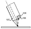
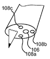
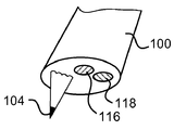
도 1a 및 1b는 베이스(103)의 표면(102)으로부터 펜 스트로크(pen strokes)의 디지털 기록을 위한 디지털 펜(100)의 일부를 개략적으로 도시한다. 표면에는 패턴(미도시)이 제공될 수 있고, 이에 의해 표면 상에서 상대적 또는 절대적인 위치 지정을 가능하게 한다. 펜(100)은 적어도 이미지되는 표면의 구역을 조명하기 위한 광원(108) 및 팁(104) 근처의 시야(field of view) 내에서 표면의 이미지를 캡쳐하기 위한 이미지 센서(106)를 포함한 광학 시스템과 팁(104)을 구비한 마킹 요소(marking element; 107)를 포함한다. 이미지 센서(106)의 광학축은 이중-도트-점선으로 도시되고, 광원(108)의 광학축은 점선으로 도시된다. 종방향 펜 축(L)은 마킹 요소(107) 및 그 팁(104)에 의해 형성된다.1A and 1B schematically illustrate a portion of a
팁(104)은 펜(100) 및 표면(102) 사이의 유일한 접촉 포인트이기 때문에, 펜의 방향은 펜의 이용 동안 상당히 변할 수 있다. 펜의 방향은 기울임 및 뒤틀림에 의해 정해질 수 있고, 펜의 기울기는 표면에 대한 수직 방향 및 펜 축(L) 사이의 각(θ)이고, 비틀림은 펜 축(L) 주위의 각(φ)이다.Since the
광원(108)으로부터의 광이 표면(102)에 도달할 때, 광의 일부는 거울 같이 반사되고, 즉 입사광과 동일한 각으로 반사되고, 일부는 베이스(103) 안으로 침투하며 되돌아 산란될 것이다. 상대적 양은 표면의 성질에 의존하지만, 광택 표면은 거울 같이 반사된 광의 더 많은 양을 일반적으로 초래할 것이다. 일정한 종류의 토너 및 프린팅 잉크는 또한 동일한 효과를 가질 수 있다. 광이 모든 방향으로 되돌아 산란되기 때문에, 주어진 방향으로 복사하는 광의 양은 표면에 투사되는 광의 양과 비교하여 비교적 작다. 거울 같이 반사된 광의 방향은 도 1a 및 1b에서 화살표의 점선으로 도시된다.When light from
펜의 일정한 방향에 대해, 이미지 센서(106)의 광학축은 베이스(103)로부터 거울 같이 반사된 광의 방향과 본질적으로 일치할 수 있다. 이러한 경우는 도 1b에서 개략적으로 도시된다. 베이스에서 광의 산란과 연관된 손실 때문에, 거울 같이 반사된 광의 밝기는 이미지 센서(106)에 도달하는 산란된 광의 밝기보다 훨씬 밝을 것이다. 따라서, 이미지는 밝은 거울 같이 반사된 광에 의해 지배될 것이고, 이러한 광은 표면 상에 제공된 어떠한 패턴을 식별하는 것을 어렵게 또는 불가능하게 만든다.For a certain direction of the pen, the optical axis of the
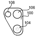
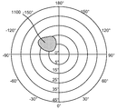
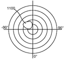
도 3은 전자펜의 상이한 방향에 대한 해독 성공 속도를 나타내는 도면에 의해 거울 같은 반사의 효과를 도시한다. 도 1a 및 1b에서 도시된 펜과 비교할 때, 이러한 도면을 얻는데 이용되는 디지털 펜은 도 2에서 도시된 것과 같이 광원(108), 이미지 센서(106) 그리고 팁(104)의 약간 상이한 기하학적 배열을 갖는다. 도 3의 도면에서, 기울임 각이 맵되는데(mapped), 이에 의해 0°는 도면의 중앙이고, 45°는 도면의 외부 둘레에 있으며, 뒤틀림 각은 -180° 내지 180° 사이에서 맵된다. 표시된 필드(1100)는 방향을 나타내고 이 방향에 대해 해독이 성공적이지 않거나 또는 불만족스러운 것으로 간주된다. 표시된 필드(1100) 외부의 방향에 대해, 해독은 만족스럽거나 또는 성공적인 것으로 간주된다. 만족스럽지 못한 해독은 광택 표면 상에서 디지털 펜의 이용시 광원으로부터 이미지 센서로 광의 거울 같은 반사로부터 초래된다.FIG. 3 shows the effect of specular reflection by means of a diagram showing the speed of decryption success for different directions of the electronic pen. Compared with the pens shown in FIGS. 1A and 1B, the digital pen used to obtain this diagram has a slightly different geometry of the
거울 같이 반사된 광의 효과는 이미지가 이미지 센서(들) 및 광원(들)의 상이한 기하학적 배열에 의해 캡쳐되는 둘 이상의 이미지 캡쳐 상태 사이에서 조정 가능한 광학 시스템을 디지털 펜에 제공함에 의해 피해지거나 또는 적어도 감소될 수 있다. 거울 같이 반사된 광의 문제점은 상이한 이미지 캡쳐 상태에서 펜의 상이한 방향에 대해 일어나기 때문에, 선택적으로 이미지 캡쳐 상태를 이용함에 의해 문제점을 피할 수 있다.The effect of specularly reflected light is avoided or at least reduced by providing the digital pen with an optical system that is adjustable between two or more image capture states where the image is captured by different geometrical arrangements of the image sensor (s) and light source (s). Can be. Since the problem of specularly reflected light occurs for different directions of the pen in different image capture states, the problem can be avoided by selectively using an image capture state.
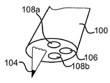
도 4에서 개략적으로 도시된 제 1 실시예에서, 디지털 펜(100)은 이미지 센서(106)로부터 이격되며 서로 떨어져 배열된 두 개의 광원(108a, 108b)을 가질 수 있다. 광원(108a) 및 이미지 센서(106)의 조합은 광원(108b) 및 이미지 센서(106)의 조합과 비교하여 상이한 기하학적 배열을 가질 것이기 때문에, 거울 같은 반사의 문제점은 상이한 이미지 캡쳐 상태에서 펜의 상이한 방향에 대해 일어날 것이다.In the first embodiment schematically shown in FIG. 4, the
광원은 광원에 대해 많은 상이한 방향에 위치할 수 있다. 사실 광원들은 표면 상에서 원하는 구역을 조명할 수 있는 한 그리고 조명 성질의 공간적 변화를 제공하도록 서로로부터 일정한 간격에 배열되는 한 어떠한 구성으로도 위치할 수 있다. 도 5는 팁(104), 광원(108a, 108b) 및 이미지 센서(106)가 정렬된 실시예를 예시적으로 도시하고, 하나의 광원은 이미지 센서의 양 측부 중 어느 하나에 위치한다.The light source can be located in many different directions relative to the light source. In fact, the light sources can be positioned in any configuration as long as they can illuminate the desired area on the surface and as long as they are arranged at regular intervals from each other to provide a spatial change in the illumination properties. 5 illustratively illustrates an embodiment in which the
다른 실시예에서, 디지털 펜(100)은 도 6에서 도시된 것처럼 둘 이상의 광원, 예를 들어 3개의 광원(108a-c)을 가질 수 있고, 이 경우 광원은 중앙에서 이미지 센서(106)를 구비한 삼각형의 코너에 위치한다. 이러한 실시예에서, 하나 이상의 광원은 둘 이상의 상이한 이미지 캡쳐 상태를 제공하기 위한 시점에서 활성화될 수 있다.In another embodiment, the
추가적인 실시예에서, 디지털 펜은 오직 하나의 광원과 서로 떨어져 위치한 둘 이상의 이미지 센서를 가질 수 있다. 센서는 선택적으로 활성화될 수 있거나 또는 평행하게 이용될 수 있다. 이러한 구성은 예를 들어 도 4-6의 어느 하나에서 유사할 수 있고, 이 경우 광원은 이미지 센서에 의해 그리고 이미지 센서는 광원에 의해 교체된다.In a further embodiment, the digital pen may have only one light source and two or more image sensors located apart from each other. The sensors can be selectively activated or used in parallel. Such a configuration can be similar for example in any of FIGS. 4-6, in which case the light source is replaced by an image sensor and the image sensor is replaced by a light source.
또 다른 실시예에서, 광원 또는 이미지 센서 또는 둘 모두는 두 개의 상이한 이미지 캡쳐 상태를 제공하도록 둘 이상의 상이한 위치 사이에서 이동 가능할 수 있다. 상이한 위치는 구성요소(들)를 각지게 함에 의해 또는 이미지축에 대해 횡방향으로 이동시킴에 의해 또는 이들의 조합에 의해 이루어질 수 있다.In yet another embodiment, the light source or image sensor or both may be movable between two or more different locations to provide two different image capture states. The different positions can be made by angled component (s) or by moving laterally relative to the image axis or by a combination thereof.
광원(들) 및/또는 이미지 센서(들)는 하나 이상의 반사체 또는 굴절체(refractor)를 포함할 수 있다. 이러한 것들은 상이한 이미지 캡쳐 상태를 얻는데 이용될 수 있다. 더욱 구체적으로 하나 이상의 반사체 또는 굴절체가 상이한 이미지 캡쳐 상태를 제공하기 위해 둘 이상의 상이한 위치 사이에서 이동 가능할 수 있다.The light source (s) and / or image sensor (s) may comprise one or more reflectors or refractors. These can be used to obtain different image capture states. More specifically, one or more reflectors or refractors may be movable between two or more different locations to provide different image capture states.
이러한 두 개의 후자의 경우에, 두 개의 상이한 이미지 캡쳐 상태는 오직 하나의 광원 및 오직 하나의 이미지 센서를 이용하여 얻어질 수 있다. 오직 하나의 광원 및 하나의 이미지 센서를 이용하여 두 개의 이미지 캡쳐 상태를 제공하는 또 다른 방법은 큰 이미지 센서를 갖는 것일 것이고, 이에 의해 상이한 이미지 캡쳐 상태가 센서의 상이한 부품을 이용함에 의해 얻어질 수 있다.In these two latter cases, two different image capture states can be obtained using only one light source and only one image sensor. Another way to provide two image capture states using only one light source and one image sensor would be to have a large image sensor, whereby different image capture states could be obtained by using different parts of the sensor. have.
도 7a 및 7b는 도 4의 실시예에 따른 디지털 펜에 대해 도 3에서와 같은 기울임 및 뒤틀림 각을 동일한 맵핑으로 도 3에서와 동일한 종류의 방향에 따라 해독 성공 속도를 도시한다. 도 7a의 도면은 제 1 광원(108a)이 이용될 때의 해독 성공 속도를 도시하는 반면, 도 7b의 도면은 제 2 광원(108b)이 이용될 때의 해독 성공 속도를 도시한다. 도 7a의 필드(1100) 및 도 7b의 필드(1102)는 해독이 만족스럽지 못한 방향을 나타낸다. 이러한 필드(1100, 1102)는 따라서 디지털 펜의 "블라인드 스팟(blind spots)"이라고 일컬어질 수 있다. 도면으로부터 분명하게 나타나는 것처럼, 이러한 필드는 이러한 경우에 겹치지 않고, 결과적으로 광원은 필드를 피하도록 선택적으로 활성화될 수 있으며 이 경우 해독은 이미지 센서에 도달하는 거울 같이 반사된 광에 의해 실패할 수 있다. 블라인드 스팟이 겹쳐지면, 겹치지 않는 블라인드 스팟을 가진 제 3 또는 그 초과의 광원이 이용될 수 있다.7A and 7B show the decoding success rate according to the same kind of direction as in FIG. 3 with the same mapping of the same tilt and twist angle as in FIG. 3 for the digital pen according to the embodiment of FIG. 7A shows the decryption success rate when the
이하에서 광학 시스템의 상이한 이미지 캡쳐 상태를 선택적으로 활성화하거나 또는 이용하는 상이한 방법이 설명될 것이다. 단순화를 위해, 설명은 도 4에서 도시된 것처럼 두 개의 광원(108a, 108b) 및 하나의 이미지 센서(106)를 포함한 광학 시스템을 참고로 하여 이루어질 것이고, 설명은 상이한 이미지 캡쳐 상태가 상기에서 설명된 것과 같은 다른 구성요소에 의해 제공되는 광학 시스템에 대해 동등하게 유효하다.In the following, different methods of selectively activating or utilizing different image capture states of the optical system will be described. For simplicity, the description will be made with reference to an optical system comprising two
일 실시예에서, 광원(108a, 108b)은 교번적인 방식으로 트리거되고, 이에 의해 제 1 광원이 표면을 조명하는 동안 매 초(every second) 이미지가 캡쳐되고 제 2 광원이 표면을 조명하는 동안 매 다른 초(every other second) 이미지가 캡쳐된다. 이러한 방식으로 적어도 매 초 이미지는 거울 같이 반사된 광으로부터의 간섭 없이 캡쳐되어야 한다. 이미지 캡쳐 주파수가 증가된다면 향상된 성능이 얻어질 수 있다.In one embodiment, the
또한, 상이한 이미지 캡쳐 상태 사이에서 스위치하기 위한 다른 고정 스케쥴을 이용하는 것을 고안할 수 있고, 이는 특히 블라인드 스팟이 해독 성공 속도-대-방향 그림에서 비대칭적으로 위치하고 및/또는 상이한 크기에 있다.It is also conceivable to use other fixed schedules for switching between different image capture states, in particular blind spots are asymmetrically located and / or at different sizes in the decoding success rate-versus-direction picture.
다른 실시예에서, 디지털 펜(100)의 방향은 트랙될 수 있고, 이에 의해 하나의 광원으로부터 나머지 광원으로의 스위치는 펜 방향이 해독 성공 속도-대-방향 그림에서 블라인드 지점으로 다가가거나 또는 들어가는 것이 탐지될 때 수행될 수 있으며, 이 경우 해독 성공 속도는 만족스럽지 못하다. 펜 방향은 디지털 펜의 방향 감지 수단에 의해 감지될 수 있고, 이는 표면 상에서 패턴의 이미지로부터 추출된 정보에 기초하여 펜의 방향을 계산하도록 구성된 프로세서 유닛 또는 지로스(gyros)의 상이한 종류를 포함할 수 있다. 예를 들면, 방향은 여기서 그 전체가 참조로 인용된 WO 01/71654 A1호에서 설명된 것과 같은 예정된 패턴의 지식과 함께 대수학적 모델을 이용함에 의해 결정될 수 있다. 감지된 또는 계산된 펜 방향은 이전에 결정된 방향과 비교될 수 있고, 이러한 방향에 대해 해독 성공 속도는 만족스럽지 못하거나/만족스러운 것으로 발견되었으며, 이에 의해 현재 펜 방향이 블라인드 지점에 있는지 또는 가까이 있는지를 확립한다. 상이한 이미지 캡쳐 상태에 대한 하나 이상의 블라인드 지점에 대응하는 펜 방향의 지시는 디지털 펜에 저장될 수 있다. 또한, 다수의 연속적인 방향 값들은, 해독이 현재 이용되는 광원-이미지센서 구성에 대해 문제점이 있는 구역에 펜 방향이 도달하는지를 확인하는데 이용될 수 있다. 또한, 예를 들어 펜 각속도 및/또는 펜 각가속도의 계산값 또는 측정값이 고려될 수 있고, 이에 의해 펜 방향이 현재 이용된 이미지 캡쳐 상태의 블라인드 지점에 도달하는지를 예측한다. 대안적인 실시예에서, 감지된 또는 계산된 펜 방향은 펜에 저장된 찾아보기 테이블로의 지표로서 이용되고, 각각의 펜 방향에 대해 광원의 스위치가 수행되어야 하는지 아닌지 그리고 둘 이상의 광원의 경우에 어떠한 광원에 스위치되는지를 나타낸다. In another embodiment, the direction of the
또 다른 실시예에서, 하나의 광원으로부터 나머지 광원으로의 스위치는 해독 성공의 평가에 기초할 수 있다. 디지털 펜이 해독이 예정된 숫자의 연속적 이미지 또는 하나의 이미지에 대해 만족스럽지 못한 결과를 주거나 또는 실패한다면, 현재 이용되는 광원은 비활성화될 수 있고 다른 광원이 활성화될 수 있다. 이미지 품질과 같은 다른 기준이 또한 나머지 광원으로의 스위치 오버가 일어날 때를 결정하기 위해 이용될 수 있다.In yet another embodiment, the switch from one light source to the other may be based on the evaluation of the decryption success. If the digital pen gives or fails an unsatisfactory result for one image or a series of images intended for decoding, the currently used light source may be deactivated and other light sources may be activated. Other criteria such as image quality can also be used to determine when switchover to the remaining light sources occurs.
일 실시예에서, 하나 이상의 캡쳐된 이미지로부터의 강도 값은 이미지 품질의 치수(measure)로서 이용될 수 있다. 이미지는 예를 들어 더 작은 부분 또는 셀로 분할될 수 있고, 최대 강도값 또는 평균 강도는 각각의 셀에 대해 결정된다. 이후 셀의 조합된 결과는, 이미지 센서 또는 그 부품이 거울 같이 반사된 광에 의해 블라인드되어 다른 이미지 캡쳐 상태로의 스위치가 실행되는지를 결정하는데 이용될 수 있다. 조합된 결과는 예를 들어 최대 강도값이 가장 높은 가능한 강도값과 동일한 경우의 셀의 숫자일 수 있다. 이후 이러한 조합된 결과는 예정된 문턱값(threshold value)과 비교될 수 있고, 이에 의해 스위치가 실행되어야 하는지에 대해 액세스한다. WO 03/030082호는 이미지의 상이한 부분으로부터의 강도값에 기초하여 디지털 펜에서 어떻게 노출 제어가 수행될 수 있는지를 설명한다. 강도값에 기초한 이미지 품질의 결정에 대한 프로세스는 노출 제어 프로세스에서 계산된 중간 결과를 이용할 수 있거나 또는 개별적인 프로세스로서 수행될 수 있다.In one embodiment, intensity values from one or more captured images may be used as a measure of image quality. The image can be divided into smaller portions or cells, for example, and the maximum intensity value or average intensity is determined for each cell. The combined result of the cell can then be used to determine whether the image sensor or its components are blinded by the specularly reflected light so that the switch to another image capture state is executed. The combined result can be, for example, the number of cells where the maximum intensity value is equal to the highest possible intensity value. This combined result can then be compared to a predetermined threshold value, thereby accessing whether the switch should be executed. WO 03/030082 describes how exposure control can be performed in a digital pen based on intensity values from different parts of an image. The process for the determination of the image quality based on the intensity value may use the intermediate result calculated in the exposure control process or may be performed as a separate process.
다른 실시예에서, 펜의 광원은 해독을 위해 이용되는 이미지의 캡쳐 사이에서 낮은 강도로 순간적으로 켜진다. 이후 센서의 하나 이상의 작은 부분, 각각의 부분이 예를 들어 2x2 픽셀일 수 있는 작은 부분이 판독되고, 판독 부분(들)의 픽셀의 강도값에 기초하여 거울 같이 반사된 광이 센서에 도달하는지 아닌지를 평가하고, 차례로 이미지 캡쳐 상태를 스위치할지 안할지를 결정한다. 이러한 실시예에 따른 평가는 매우 짧은 시간에 수행될 수 있는데, 왜냐하면 소수의 픽셀만이 센서로부터 판독될 필요가 있기 때문이다. 또한, 광원의 충전은 최소 정도로 영향을 받고 전력 소비에도 마찬가지이다.In another embodiment, the light source of the pen is turned on momentarily with low intensity between the capture of the image used for decryption. Then one or more small portions of the sensor, small portions where each portion can be, for example, 2x2 pixels, are read out and whether mirror-reflected light reaches the sensor based on the intensity value of the pixel of the reading portion (s). Evaluate and in turn decide whether to switch the image capture state. The evaluation according to this embodiment can be performed in a very short time, since only a few pixels need to be read from the sensor. In addition, the charging of the light source is affected to a minimum and the power consumption is also the same.
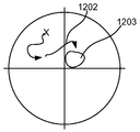
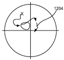
도 8a-8c는 도 4에서와 같은 두 개의 광원 및 하나의 이미지 센서를 가진 디지털 펜에 대한 방향에 따른 해독 성고 속도의 개략도를 도시한다. 기울임 및 뒤틀림의 맵핑은 도 3에서와 동일하다. 도 8a는 사용자가 시작에서 펜의 방향을 나타내는 X를 가진 디지털 펜을 이용하여 시작할 때 호라성화되는 광원에 대해 이용 가능한 그림을 도시한다. 펜의 이후의 작동 동안, 방향은 화살표 라인(1200)에 의해 표시되는 것처럼 변한다. 화살표 라인(1200)의 끝에서, 방향은 블라인드 지점(1201)에 도달하고, 여기서 해독은 거울같이 반사된 광에 의한 문제일 수 있다. 이러한 영역에 대한 접근은 상기에서 설명된 것처럼 펜의 현재 방향을 결정함에 의해 탐지될 수 있다. 블라인드 지점(1201)의 접근이 탐지될 때, 제 1 광원이 비활성화되고 제 2 광원이 활성화되며, 이에 의해 도 8b에서 도시된 해독 성공 속도-대-방향 그림이 이용 가능한 것이 된다. 방향은 제 2 화살표 라인(1202)에 따라 계속 변한다. 제 2 화살표 라인(1202)의 단부에서, 방향은 블라인드 지점(1203)에 도달하고, 여기서 해독은 거울 같이 반사된 광에 의해 문제가 될 수 있다. 상기 설명된 것과 유사한 방식으로, 펜은 제 1 광원으로 되돌아 가도록 스위치되고, 이에 의해 도 8a에서 도시된 해독 성공 속도-대-방향 그림이 이용 가능한 하나가 된다. 그러나, 사건의 과정을 더 잘 도시하기 위해, 도 8a의 그림은 도 8c에서 반복되고, 이 경우 화살표는 펜의 이용 동안 펜 방향의 변화를 도시한다. 이러한 방향은 해독 문제가 예상될 수 있는 경우에 어떠한 영역에 들어감 없이 제 3 화살표 라인(1204)에 따라 계속 변화한다. 이러한 방식으로 광학 시스템을 작동시킴에 의해, 향상된 해독 속도가 얻어질 수 있다.8A-8C show schematic diagrams of the decipherment speed along the direction for a digital pen with two light sources and one image sensor as in FIG. 4. The mapping of the tilt and distortion is the same as in FIG. 3. 8A shows a picture available for a light source that is activated when the user starts using a digital pen with X indicating the direction of the pen at the start. During subsequent operation of the pen, the direction changes as indicated by
대안적인 또는 보충적인 실시예에 따르면, 거울 같이 반사된 광의 문제는 이미지 센서 앞에서 제 1 편광 방향의 선형으로 편광된 광으로 표면을 비추고 이미지 센서 앞에서 제 2 상이한 편광 방향을 가진 선형 편광기를 위치시킴에 의해 피해지거나 또는 감소될 수 있다.According to an alternative or supplementary embodiment, the problem of specularly reflected light is to illuminate the surface with linearly polarized light in a first polarization direction in front of the image sensor and to position a linear polarizer with a second different polarization direction in front of the image sensor. Can be avoided or reduced.
이러한 해법은 표면에서 거울 같이 반사되는 선형으로 편광된 광이 선형 편광을 큰 정도로 유지할 것이라는 이해에 기초한다. 반대로 표면을 통과하며 베이스에서 산란되는 광은 그 선형 편광을 유지하지 못할 것이다. 따라서, 광원 및 표면 사이의 광학 경로에 제 1 편광기를 그리고 표면 및 이미지 센서 사이의 광학 경로에 제 2 편광기를 위치시킴에 의해, 그리고 제 1 편광기의 방향에 거의 수직한 편광 방향을 가진 채로, 베이스에서 산란되었던 광이 오직 이미지 센서에 도달할 것이다. 이러한 방식으로 거울 같은 반사의 부정적 영향을 피할 수 있다. 이러한 해법의 단점은 편광기가 광의 비교적 큰 부분을 흡수할 수 있다는 점일 수 있다. 이러한 손실은 예를 들어 레이저 다이오드와 같은 선형으로 편광된 광을 자체적으로 방출하는 광원을 이용함에 의해 감소될 수 있다. 이러한 경우에 제 1 편광기는 이용될 필요가 없다. 또한 둘 이상의 광원이 편광기에 의해 광의 흡수를 보상하는데 이용될 수 있다. 이러한 경우에 거의 동일한 편광 방향을 가진 선형 편광기는 광원 앞에 위치해야만 한다. 대안적으로, 동일한 편광 방향의 선형으로 편광된 광을 방출하는 광원이 이용될 수 있다.This solution is based on the understanding that linearly polarized light that is mirrored at the surface will maintain linear polarization to a large extent. Conversely, light that passes through the surface and scatters at the base will not maintain its linear polarization. Thus, by positioning the first polarizer in the optical path between the light source and the surface and the second polarizer in the optical path between the surface and the image sensor, and with the polarization direction nearly perpendicular to the direction of the first polarizer, The light scattered at will only reach the image sensor. In this way, the negative effects of mirror-like reflections can be avoided. A disadvantage of this solution may be that the polarizer can absorb a relatively large portion of the light. This loss can be reduced by using a light source that emits itself linearly polarized light, for example a laser diode. In this case the first polarizer need not be used. Two or more light sources may also be used to compensate for the absorption of light by the polarizer. In this case a linear polarizer with nearly the same polarization direction must be located in front of the light source. Alternatively, a light source can be used that emits linearly polarized light in the same polarization direction.
하나 이상의 편광기 또는 편광 방향에 영향을 미치는 다른 구성요소가 제 1 및 제 2 편광기 사이의 광학 경로에서 이용된다면, 제 2 편광기의 편광 방향을 선택할 때 이것이 고려되어야 한다. 일반적으로, 제 2 편광기의 편광 방향은 제 1 편광기에 의해 선형으로 편광된 광의 투과 강도가 최소화되도록 선택되어야 한다.If one or more polarizers or other components affecting the polarization direction are used in the optical path between the first and second polarizers, this should be taken into account when selecting the polarization direction of the second polarizer. In general, the polarization direction of the second polarizer should be chosen such that the transmission intensity of light linearly polarized by the first polarizer is minimized.
도 9는 디지털 펜(100)의 일부를 개략적으로 도시하고, 여기서 제 1 선형 편광기(118)는 광원 앞에 위치하며 제 2 선형 편광기(116)는 이미지 센서 앞에 위치한다. 상이한 편광 방향은 사선으로 도시된다. 이상적으로 편광 방향은 서로에 대해 수직이지만, 편광기는 거울 같이 반사되는 광의 대부분을 흡수할 다른 각진 구성으로 위치할 수도 있다.9 schematically illustrates a portion of the
상기 실시예에서, 편광기(들)은 영구적으로 이용된다. 다른 실시예에서, 편광기(들)은 거울 같이 반사되는 광이 예상되거나 또는 탐지되기 때문에 문제를 해독할 때만 이용될 수 있다. 이러한 이용은 둘 이상의 광원 또는 이미지 센서가 선택적으로 이용될 때 상기에서 설명된 것에 대응한다. 특히, 거울같이 반사된 광을 흡수하는 편광기 없이 수행된 이미지 캡쳐는 제 1 이미지 캡쳐 상태를 나타낼 것이고, 거울같이 반사된 광을 흡수하는 편광기를 이용한 이미지 캡쳐는 제 2 이미지 캡쳐 상태를 나타낼 것이다. 편광기(들)은 광학 경로 안으로 이동될 수 있거나 또는 이용될 때 바로 활성화될 수 있다.In this embodiment, the polarizer (s) is used permanently. In other embodiments, the polarizer (s) may only be used to decode the problem because specularly reflected light is expected or detected. This use corresponds to that described above when two or more light sources or image sensors are selectively used. In particular, image capture performed without a polarizer absorbing specularly reflected light will represent a first image capture state, and image capture with a polarizer absorbing specularly reflected light will represent a second image capture state. The polarizer (s) may be moved into the optical path or may be activated immediately when used.
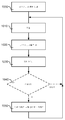
도 10은 도 4의 디지털 펜(100)과 같은 두 개의 이미지 캡쳐 상태를 가진 디지털 펜의 광학 시스템이 어떻게 거울 같이 반사된 광에 의해 야기된 문제점을 피하도록 제어될 수 있는지를 개략적으로 도시하는 흐름도이다. 박스(1000)에 의해 나타낸 것처럼, 제 1 이미지 캡쳐 상태는 디지털 펜이 활성화될 때 이용된다. 방법의 제 1 단계(1010)에서, 현재 이미지 캡쳐 상태에서 이용된 광원은 팁의 근처의 표면을 비추도록 켜진다. 조명이 켜진 동안 이미지는 이미지 센서에 의해 캡쳐된다(단계 1020). 이후의 단계(1030)에서, 위치 해독이 수행되거나 또는 적어도 시도된다. 위치 해독의 결과는 실패했기 때문에 또는 결과가 확실하지 않은 것으로 나타났기 때문에 만족스럽거나 또는 불만족스러울 수 있다. 일 실시예에서, 다음 단계는 다른 이미지 캡쳐 상태로 강제적으로 스위치하는 것이고(단계 1050), 이에 의해 모든 제 2 이미지는 하나의 이미지 캡쳐 상태에서 그리고 다른 이미지는 나머지 이미지 캡쳐 상태에서 캡쳐된다. 다른 실시예에서, 위치 해독 단계는 평가 단계(1040) 이후에 있고, 이 경우 나머지 이미지 캡쳐 상태로의 스위치가 실행될지 안될지가 결정된다. 상기에서 표시된 것처럼, 평가는 하나 이상의 방향 값들, 해독 단계의 결과, 평가된 이미지 품질 또는 다른 수단에 기초할 수 있다. 평가 단계의 결과는 이미지 캡쳐 상태가 변화된다면, 다른 이미지 캡쳐 상태로의 스위치가 단계(1050)에서 수행되고, 이후 유동은 단계(1010)으로 되돌아가며, 나머지 유동은 직접 단계(1010)으로 되돌아가고, 다음 이미지는 동일한 이미지 캡쳐 상태에서 캡쳐된다.FIG. 10 is a flow chart that schematically illustrates how an optical system of a digital pen with two image capture states, such as the
광학 시스템이 둘 이상의 이미지 캡쳐 상태를 포함한다면, 그 방법은 선택 단계를 포함할 수도 있고, 이 단계에서 스위치가 실행되어야 하는 특정 이미지 캡쳐 상태가 선택된다.If the optical system includes more than one image capture state, the method may include a selection step, in which the specific image capture state for which the switch should be executed is selected.
이러한 방법은 디지털 펜에서 전체적으로 수행될 수 있지만, 또한 펜과 통신하는 하나 이상의 외부 유닛 및 디지털 펜 사이에서 분할될 수 있다. 이러한 방법의 단계는 소프트웨어, 하드웨어 또는 펌웨어에 의해 구현될 수 있다.This method may be performed entirely on a digital pen, but may also be split between the digital pen and one or more external units in communication with the pen. The steps of this method may be implemented by software, hardware or firmware.
위에서 거울 같이 반사된 광에 의해 야기된 해독 문제를 감소시키기 위해 설계된 광학 시스템을 가진 디지털 펜(100)은 도 4-6 및 9를 참고로 하여 설명되었다. 이미 표시된 것처럼 이러한 디지털 펜은 팁(104)을 가진 마킹 요소(107), 하나 이상의 이미지 센서(106) 그리고 서로 이격되어 위치한 하나 이상의 광원(108)을 포함할 수 있다. 마킹 요소(107)는 디지털 펜이 이용될 때 표면 상에 마크를 남기도록 이루어지거나 또는 이루어지지 않을 수 있다. 마킹 요소(107)가 표면 상에 시각적 마크를 남기도록 이루어진다면, 이는 잉크 카트리지, 롤러 볼, 펜슬, 펠트 팁 카트리지(felt tip cartridge) 또는 완전한 화이트보드 또는 마커 펜과 같은 구조를 포함할 수 있다. 마킹 요소(107)는 교체 가능할 수 있다. 각각의 이미지 센서(106)는 예를 들면 CCD 또는 CMOS 센서 혹은 다른 카메라 같은 장치를 포함할 수 있다. 이는 가시광 및/또는 비가시광에 민감할 수 있다. 각각의 광원(108)은 하나 이상의 선택적으로 작동 가능한 LED 또는 레이저 다이오드 또는 다른 조명 장치를 포함할 수 있다. 표면 상에서 펜 스트로크를 형성하기 위해 사용자의 손에 의해 조작될 수 있는 한, 디지털 펜은 특별한 형상 또는 비율을 가질 필요는 없다.The
도 11은 거울같이 반사된 광에 의해 야기된 문제점을 감소시키기 위한 광학 시스템이 이용될 수 있는 예시적인 디지털 펜(100)을 더욱 상세하게 도시한다. 펜은 윈도우 또는 개구(122)를 형성하는 펜 형상의 케이스 또는 쉘(120)을 갖고, 이러한 윈도우 또는 개구를 통해 이미지가 기록된다.FIG. 11 illustrates in more detail an exemplary
도 11의 예시적 디지털 펜(100)의 광학 시스템은 두 개의 조명 광원(108), 렌즈 배열체(도면에서 미도시) 그리고 광학 이미지 센서(106)를 포함한다. 광원(108), 적절하게 발광 다이오드(LED) 또는 레이저 다이오드는 예를 들어 적외선 복사와 같은 조명 복사에 의해 윈도우를 통해 볼 수 있는 구역의 일부분을 선택적으로 조명한다. 보이는 이미지는 렌즈 배열체에 의해 이미지 센서(106) 상에 투사된다. 이미지 센서는 일반적으로 약 70-100Hz의 고정 또는 가변 속도로 이미지를 캡쳐하도록 트리거된 2차원 CCD 또는 CMOS 탐지기일 수 있다.The optical system of the exemplary
펜을 위한 전력 공급 장치는 배터리(124)일 수 있고, 이는 대안적으로 메인 전력(미도시)에 의해 교체 또는 보충될 수 있다.The power supply for the pen may be a
디지털 펜(100)에는 하나 이상의 프로세서(128) 및 메모리 블록(130)을 포함한 프로세싱 모듈(126)이 추가적으로 제공될 수 있다. 프로세싱 모듈은 거울 같은 반사를 피하기 위해 광학 시스템의 제어, 노출 제어 및 위치 제어와 같은 펜에서의 상이한 기능을 책임질 수 있고, FPGA("필드 프로그램 가능한 게이트 어레이") 또는 대안적으로 ASIC("응용-특정 일체화된 회로"), 불연속적인 아날로그 및 디지털 구성요소, 또는 이들의 조합과 같은 일정한 다른 프로그램 가능한 논리 장치에 의해, 또는 DSP("디지털 신호 프로세서")에 의해 CPU("중앙 처리 유닛")와 같은 상업적으로 이용 가능한 마이크로프로세서에 의해 구현될 수 있다. 메모리 블록(130)은 작업 메모리(예를 들어 RAM) 및 프로그램 코드 및 영속적인 저장 메모리(비휘발성 메모리, 예를 들어 플래쉬 메모리)와 같은 상이한 유형의 메모리를 포함할 수 있다. 연관된 펜 소프트웨어는 메모리 블록(130)에 저장될 수 있고, 디지털 펜의 작동을 위한 펜 제어 시스템을 제공하기 위해 프로세싱 모듈에 의해 실행될 수 있다.The
케이싱(120)은 마킹 요소(107)를 수반하고, 이러한 마킹 요소는 사용자가 표면 상에 증착되는 마킹 잉크에 의해 표면 상에 물리적으로 쓰거나 또는 그리는 것을 가능하게 한다. 마킹 요소(107)의 마킹 잉크는 조명 복사에 투명한 것이 적절하고, 이에 의해 디지털 펜에서의 광전자 탐지와의 간섭을 피한다. 접촉 센서(132)는 마킹 요소(107)에 작동적으로 연결될 수 있고, 이에 의해 펜이 표면에 인가될 때(펜 다운) 및/또는 표면으로부터 들어올려질 때(펜 업)를 탐지하고 선택적으로 인가력의 결정을 가능하게 한다. 펜 스트로크는 펜 다운 및 이후의 펜 업에 의해 정의될 수 있다. 접촉 센서(132)의 출력에 기초하여, 광학 시스템은 펜 다운 및 펜 업 사이의 이미지를 캡쳐하기 위해 프로세싱 모듈에 의해 제어될 수 있다. 프로세싱 모듈(126)은 이후 코딩 패턴(coding pattern)의 이미지된 부분에 의해 인코딩된 위치를 계산하기 위해 이미지 데이터를 처리할 수 있다. 이러한 프로세싱은 예를 들어 출원인의 종래 공개 문헌에 따라 구현될 수 있다: US 2003/0053699, US 2003/0189664, US 2003/0118233, US 2002/0044138, US 6,667,695, US 6,732,927, US 2003/0122855, US 2003/0128194 및 그 안의 참고 문헌들. 일시적으로 일관적인 위치의 결과적인 순서는 펜 스트로크의 디지털 표시를 형성한다.Casing 120 involves marking
프로세싱 모듈(126)은 광학 시스템이 상기에서 설명된 것과 같은 이미지 캡쳐 상태를 변화시키도록 제어할 수 있고, 이에 의해 거울 같이 반사된 광의 문제점을 피한다. 또한, 상이한 이미지 캡쳐 상태로의 스위치가 실행되었는지를 확립할 목적의 평가를 수행할 수도 있다. 이러한 평가는 펜 방향이 결정될 것을 요구할 수 있다. 이러한 목적을 위해, 디지털 펜에는 방향 감지 수단(도면에서는 미도시)이 제공될 수 있고, 이로부터 프로세싱 모듈은 방향 값(기울기 및/또는 뒤틀림)을 받는다. 다른 실시예에서, 프로세싱 모듈(126)은 이미지의 내용을 이용하여 방향 값을 계산하도록 구성될 수 있다.The
디지털 펜은 독립적인 장치 또는 외부 장치로 기록된 데이터를 전달하기 위한 장치일 수 있다. 후자의 경우에, 디지털 펜은 컴퓨터, 휴대 전화기, PDA, 네트워크 서버 등과 같은 인근 또는 원격 장치로 데이터를 전송 또는 노출시키기 위한 통신 인터페이스(134)를 추가적으로 포함할 수 있다. 통신 인터페이스(134)는 따라서 와이어 또는 와이어리스 단범위(short range) 통신(예를 들어 USB, RS232, 라디오 통신, 적외선 통신, 초음파 통신, 유도 커플링 등)을 위한 구성요소 및/또는 일반적으로 컴퓨터, 전화 또는 위성 통신 네트워크를 통한 와이어 또는 와이어리스 원격 통신을 위한 구성요소를 제공할 수 있다.The digital pen may be an independent device or a device for transferring recorded data to an external device. In the latter case, the digital pen may further include a
또한, 펜은 사용자 피드백을 위한 펜 제어 시스템에 의해 선택적으로 활성화될 수 있는 MMI(인간 기계 인터페이스)를 포함할 수 있다. MMI는 디스플레이, 표시자 램프, 진동자, 스피커 등을 포함할 수 있다.The pen may also include a human machine interface (MMI) that can be selectively activated by a pen control system for user feedback. The MMI may include a display, an indicator lamp, an oscillator, a speaker, and the like.
추가적으로, 펜은 하나 이상의 버튼을 포함할 수 있고, 이에 의해 펜이 활성화 및/또는 제어될 수 있다.Additionally, the pen can include one or more buttons, whereby the pen can be activated and / or controlled.
디지털 펜은 정보를 전송하기 위해 사용자에 의해 트리거될 때가지 정보를 저장하거나 또는 외부 장치로 실시간으로 다소간 기록된 정보를 전송하도록 구성될 수 있다. 일 실시예에서, 펜의 기능성은 외부 장치로 이미지 정보의 전송 및 이미지의 캡쳐에 제한될 수 있다. 다른 실시예에서, 디지털 펜은 이미지로부터 위치 정보를 해독할 수 있고, 해독된 위치에 응답하여 일정한 작동을 수행할 수 있다.The digital pen may be configured to store information until triggered by a user to transmit the information or to transmit the recorded information in real time to an external device in real time. In one embodiment, the functionality of the pen may be limited to the transmission of image information and capture of images to an external device. In another embodiment, the digital pen can decrypt location information from an image and perform certain operations in response to the decrypted location.
다른 실시예에서, 디지털 펜은 화이트보드 상에서 만들어진 펜 스트로크를 디지털적으로 기록하기 위해 화이트보드 상에서 이용되도록 구성될 수 있다. 이러한 경우에, 마킹 요소는 완전한 화이트보드 펜일 수 있고, 이 펜은 이러한 목적을 위해 탈착 가능할 수 있는 케이싱에 삽입될 수 있다. 이러한 실시예에서, 접촉 센서는 케이싱의 상단부에 제공된 기계적 스위치일 수 있고, 이에 의해 화이트보드 펜은 디지털 펜이 화이트보드 상에서 이용될 때 스위치에 대해 프레스된다. 디지털 펜은 화이트 보드 상에서 흔적을 남기거나 또는 남기지 않을 수 있다.In another embodiment, the digital pen may be configured to be used on a whiteboard to digitally record pen strokes made on the whiteboard. In this case, the marking element can be a complete whiteboard pen, which can be inserted into a casing which can be removable for this purpose. In this embodiment, the contact sensor may be a mechanical switch provided at the upper end of the casing, whereby the whiteboard pen is pressed against the switch when the digital pen is used on the whiteboard. The digital pen may or may not leave a trace on the whiteboard.
디지털 펜은 절대-위치지정 펜일 필요는 없지만, 대신 디지털 방식으로 펜 스트로크를 기록하기 위해 연속적으로 캡쳐된 이미지의 내용을 매칭함에 의해 상대적 위치를 결정하도록 구성될 수 있다. 또한, 펜은 절대적 및 상대적 위치 지정의 조합을 허용할 수 있다.The digital pen need not be an absolute-positioning pen but can instead be configured to determine the relative position by matching the content of the continuously captured image to digitally record the pen stroke. In addition, the pen can allow a combination of absolute and relative positioning.
또 다른 실시예에서, 디지털 펜은 소위 포인트-및-클릭 펜이고, 이러한 펜은 펜 스트로크를 기록하기 위해 이용되는 것이 아니라 패턴화된 표면에서 포인트 하는데만 이용되고, 이에 의해 작동을 개시하거나 또는 이미지의 내용에 기초한 일정한 종류의 피드백을 얻는다. 포인트-및-클릭 펜(point-and-click pen)이 절대 위치 코딩 패턴 상에서 이용된다면, 이미지된 패턴 부분으로부터 해독된 절대 위치는 예를 들면 디지털 펜이 특정 작동을 개시하거나 또는 특정 종류의 피드백을 주기 위한 명령을 나타낼 수 있다.In another embodiment, the digital pen is a so-called point-and-click pen, which is not used to record pen strokes, but only to point at a patterned surface, thereby initiating an operation or image Get some kind of feedback based on If a point-and-click pen is used on the absolute position coding pattern, the absolute position decoded from the imaged pattern portion may, for example, cause the digital pen to initiate a particular operation or provide some kind of feedback. It can represent a command to give.
상이한 패턴이 표면 상에서 이용될 수 있고, 이에 의해 디지털 펜이 표면 상에서 상대적 또는 절대적 위치를 결정하는 것을 가능하게 한다. 패턴은 다소 복잡한 상징에 의해 이루어질 수 있고, 하나 이상의 상징은 위치를 정의할 수 있다. 일 패턴의 일 종류에서, 주어진 크기를 가진 패턴의 각각의 부분은 고유할 수 있고, 이에 의해 고유의 절대적 위치를 형성한다. 대안적으로, 표면은 위치를 각각 형성하는 패턴 부분으로 타일될 수 있다. 패턴 부분은 원하는 이용에 따라 원하는 대로 반복될 수 있다. 패턴은 위치-코딩 패턴일 필요는 없다. 대안적으로 예를 들어 랜덤화된 패턴과 같은 비위치 코딩 패턴일 수 있고, 디지털 펜은 연속적으로 캡쳐된 이미지를 매치함에 의해 상대적 위치를 결정하는데 이용된다.Different patterns can be used on the surface, thereby enabling the digital pen to determine relative or absolute positions on the surface. Patterns can be made by more or less complex symbols, and one or more symbols can define a location. In one kind of pattern, each portion of the pattern with a given size may be unique, thereby forming a unique absolute position. Alternatively, the surface may be tiled into pattern portions that each form a location. The pattern portion can be repeated as desired depending on the desired use. The pattern need not be a location-coding pattern. Alternatively, it may be a non-position coding pattern such as, for example, a randomized pattern, and the digital pen is used to determine the relative position by matching successively captured images.
여기서 참조로 모두 인용된 미국 특허 제 6,663,008호 및 6,667,695호는 수기의 디지털 기록을 위한 디지털 펜에 의해 이용될 수 있는 첫번째 언급된 유형의 위치-코딩 패턴(position-coding pattern)을 개시한다. 특히, 상기 언급된 특허에서 개시된 패턴은 유사한 크기 및 형상의 도트(dots)에 의해 구성된다. 예를 들어 6*6 도트와 같은 예정된 숫자의 도트의 세트는 고유의 위치를 형성할 수 있다. 상기 언급된 특허에서 설명된 것처럼, 각각의 도트는 시각적으로 사각형인 그리드(grid)에서 그리드 위치로부터 4개의 예정된 방향 중 하나로 변위됨에 의해 4개의 가능한 값 중 하나를 인코드할 수 있다. 상이한 도트의 변위의 방향은 패턴이 생성될 때 수학적 알고리즘에 따라 계산될 수 있다. 이론적으로, 436의 상이한 위치가 상기 언급된 파라미터를 가진 패턴에서 인코드될 수 있다. 패턴은 대략 0.3mm의 그리드 포인트 사이에서 공칭 공간(nominal spacing)을 가진 채로 구현될 수 있고, 이는 고해상도를 가진 수기를 기록하는데 적절하다. 이러한 배턴 배열은 전체 패턴이 유럽과 아시아가 조합된 표면 영역과 거의 동일한 표면 영역을 커버하는 것을 허용한다. 따라서, 도 1a 및 1b의 표면(102)과 같이 전체 패턴의 아주 작은 퍼센트 또는 부분 만이 표면 상에 제공될 필요가 있고, 이에 의해 수기를 디지털 기록하는 것을 가능하게 한다.US Pat. Nos. 6,663,008 and 6,667,695, both of which are incorporated herein by reference, disclose a first-mentioned type of position-coding pattern that can be used by a digital pen for handwritten digital recording. In particular, the pattern disclosed in the above-mentioned patent is constituted by dots of similar size and shape. For example, a set of predetermined number of dots, such as 6 * 6 dots, may form a unique position. As described in the above-mentioned patent, each dot can encode one of four possible values by being displaced in one of four predetermined directions from the grid position in a visually rectangular grid. The direction of displacement of the different dots can be calculated according to a mathematical algorithm when the pattern is generated. Theoretically, 4 36 different positions can be encoded in the pattern with the above mentioned parameters. The pattern can be implemented with nominal spacing between grid points of approximately 0.3 mm, which is suitable for recording handwriting with high resolution. This baton arrangement allows the entire pattern to cover almost the same surface area as the surface area in which Europe and Asia are combined. Thus, only a small percentage or portion of the overall pattern, such as
이러한 패턴은 페이퍼 스톡, 반투명 물질 상에 프린트될 수 있거나, 또는 첨부되거나 혹은 디스플레이될 수 있는 표면 또는 물질 상에서 나타나는 것을 야기할 수 있다. 예를 들면, 패턴은 프로젝터를 통해 또는 다른 디스플레이 장치를 이용하여 비디오 스크린, 컴퓨터 스크린 상에서와 같이 동적으로 디스플레이될 수 있다.Such a pattern can result in being printed on paper stock, translucent material, or on a surface or material that can be attached or displayed. For example, the pattern may be displayed dynamically, such as on a video screen, computer screen, through a projector or using another display device.
변위된 도트에 대한 대안으로서, 수기를 기록하는 것을 가능하게 하는 패턴은 상이한 크기, 정확한 각(right angles), 슬래쉬, 캐릭터, 컬러 패턴 또는 다른 프린트된 형상 또는 표시의 도트들 중 하나 이상을 포함할 수 있다.As an alternative to displaced dots, the pattern that makes it possible to record handwriting may comprise one or more of dots of different sizes, right angles, slashes, characters, color patterns or other printed shapes or indicia. Can be.
상기 설명된 발명을 잠재적으로 이용할 수 있는 다른 위치-코딩 패턴 및 디지털 펜의 예는 예를 들어 US 6,752,317; WO 99/50787; US 5,661,506; US 5,652,412; US 5,852,434; US 5,442,147; 및 WO 00/25293에서 발견된다.Examples of other position-coding patterns and digital pens that could potentially utilize the invention described above are described, for example, in US 6,752,317; WO 99/50787; US 5,661,506; US 5,652,412; US 5,852,434; US 5,442,147; And WO 00/25293.
Claims (16)
상기 디지털 펜이 작동하는 동안 상기 패턴화된 표면의 이미지를 캡쳐하기 위한 상기 패턴화된 표면 상의 하나 이상의 센서 및 상기 하나 이상의 센서에 의해 이미지가 캡쳐될 때 상기 패턴화된 표면을 조명하기 위한 하나 이상의 광원을 구비한 광학 시스템을 포함하고,
상기 광학 시스템은 둘 이상의 이미지 캡쳐 상태 사이에서 조정 가능하며, 상기 둘 이상의 이미지 캡쳐 상태에서 상기 하나 이상의 센서 및 상기 하나 이상의 광원의 상이한 기하학적 배열로 이미지가 캡쳐되는,
패턴화된 표면을 이용하여 정보를 디지털 기록하기 위한 디지털 펜.
A digital pen for digitally recording information using a patterned surface,
One or more sensors on the patterned surface for capturing an image of the patterned surface while the digital pen is in operation and one or more for illuminating the patterned surface when the image is captured by the one or more sensors. An optical system with a light source,
The optical system is adjustable between two or more image capture states, wherein images are captured with different geometric arrangements of the one or more sensors and the one or more light sources in the two or more image capture states,
Digital pen for digitally recording information using patterned surfaces.
상기 광학 시스템은 둘 이상의 광원을 포함하고,
상기 디지털 펜은 제 1 및 제 2 이미지 캡쳐 상태에서 상이한 광원을 활성화시키도록 이루어지는,
패턴화된 표면을 이용하여 정보를 디지털 기록하기 위한 디지털 펜.
The method of claim 1,
The optical system comprises two or more light sources,
The digital pen is configured to activate different light sources in a first and a second image capture state,
Digital pen for digitally recording information using patterned surfaces.
상기 광학 시스템은 둘 이상의 센서를 포함하고,
상기 디지털 펜은 제 1 및 제 2 이미지 캡쳐 상태에서 상이한 이미지 센서로부터 이미지를 회수하도록 이루어지는,
패턴화된 표면을 이용하여 정보를 디지털 기록하기 위한 디지털 펜.
The method of claim 1,
The optical system comprises two or more sensors,
The digital pen is adapted to retrieve an image from a different image sensor in a first and a second image capture state,
Digital pen for digitally recording information using patterned surfaces.
상기 하나 이상의 펜 및 상기 하나 이상의 광원 중 하나 이상은 제 1 및 제 2 위치 사이에서 이동 가능한,
패턴화된 표면을 이용하여 정보를 디지털 기록하기 위한 디지털 펜.
The method of claim 1,
At least one of the at least one pen and the at least one light source is movable between first and second positions,
Digital pen for digitally recording information using patterned surfaces.
상기 디지털 펜은 예정된 스케쥴에 따라 상기 둘 이상의 이미지 캡쳐 상태 사이에서 스위치 되도록 이루어진,
패턴화된 표면을 이용하여 정보를 디지털 기록하기 위한 디지털 펜.
The method according to any one of claims 1 to 4,
Wherein the digital pen is configured to switch between the two or more image capture states in accordance with a predetermined schedule,
Digital pen for digitally recording information using patterned surfaces.
상기 디지털 펜은 상기 펜의 작동에 따라 선택적으로 상기 이미지 캡쳐 상태를 변화시키도록 이루어진,
패턴화된 표면을 이용하여 정보를 디지털 기록하기 위한 디지털 펜.
The method according to any one of claims 1 to 4,
The digital pen is configured to selectively change the image capture state in accordance with the operation of the pen,
Digital pen for digitally recording information using patterned surfaces.
상기 디지털 펜의 방향을 결정하기 위한 수단을 포함하고,
상기 디지털 펜은 상기 펜의 방향에 기초하여 선택적으로 상기 이미지 캡쳐 상태를 변화시키도록 이루어진,
패턴화된 표면을 이용하여 정보를 디지털 기록하기 위한 디지털 펜.
The method according to claim 6,
Means for determining the orientation of the digital pen,
The digital pen is configured to selectively change the image capture state based on a direction of the pen,
Digital pen for digitally recording information using patterned surfaces.
상기 디지털 펜은 상기 표면 상에서 절대 위치-코딩 패턴(absolute position-coding pattern)에 의해 펜 스트로크를 전자적으로 기록하도록 이루어진,
패턴화된 표면을 이용하여 정보를 디지털 기록하기 위한 디지털 펜.
The method according to any one of claims 1 to 7,
Wherein the digital pen is adapted to electronically record pen strokes by an absolute position-coding pattern on the surface.
Digital pen for digitally recording information using patterned surfaces.
상기 디지털 펜이 작동하는 동안 상기 패턴화된 표면의 이미지를 캡쳐하기 위한 상기 패턴화된 표면 상의 하나 이상의 센서 및 상기 하나 이상의 센서에 의해 이미지가 캡쳐될 때 상기 패턴화된 표면을 조명하기 위한 하나 이상의 광원을 구비한 광학 시스템을 포함하고,
상기 디지털 펜은 제 1 편광 방향을 가진 선형으로 편광된 광으로 상기 패턴화된 표면을 조명하도록 구성되며,
제 2 상이한 편광 방향을 가진 선형 편광기는 상기 하나 이상의 이미지 센서의 전방에 제공되는,
패턴화된 표면을 이용하여 정보를 디지털 기록하기 위한 디지털 펜.
A digital pen for digitally recording information using a patterned surface,
One or more sensors on the patterned surface for capturing an image of the patterned surface while the digital pen is in operation and one or more for illuminating the patterned surface when the image is captured by the one or more sensors. An optical system with a light source,
The digital pen is configured to illuminate the patterned surface with linearly polarized light having a first polarization direction,
A linear polarizer having a second different polarization direction is provided in front of the at least one image sensor,
Digital pen for digitally recording information using patterned surfaces.
제 1 편광 방향을 가진 상기 선형으로 편광된 광을 제공하기 위한 상기 하나 이상의 광원 전방에 다른 선형 편광기를 포함하는,
패턴화된 표면을 이용하여 정보를 디지털 기록하기 위한 디지털 펜.
The method of claim 9,
A different linear polarizer in front of said at least one light source for providing said linearly polarized light with a first polarization direction,
Digital pen for digitally recording information using patterned surfaces.
상기 하나 이상의 광원은 선형으로 편광된 광을 방출하는 광원인,
패턴화된 표면을 이용하여 정보를 디지털 기록하기 위한 디지털 펜.
The method according to claim 9 or 10,
The at least one light source is a light source that emits linearly polarized light,
Digital pen for digitally recording information using patterned surfaces.
상기 디지털 펜이 작동하는 동안 상기 패턴화된 표면의 이미지를 캡쳐하기 위한 상기 패턴화된 표면 상의 하나 이상의 센서 및 상기 하나 이상의 센서에 의해 이미지가 캡쳐될 때 상기 패턴화된 표면을 조명하기 위한 하나 이상의 광원을 구비한 광학 시스템을 포함하고,
상기 하나 이상의 광원 및 상기 하나 이상의 센서의 제 1 기하학적 배열을 이용하여 제 1 이미지 캡쳐 상태에서 제 1 이미지를 캡쳐하는 단계와 상기 하나 이상의 광원 및 상기 하나 이상의 센서의 제 2 기하학적 배열을 이용하여 제 2 이미지 캡쳐 상태에서 제 2 이미지를 캡쳐하는 단계를 포함하는,
패턴화된 표면 및 디지털 펜을 이용하여 정보를 디지털 기록하는 방법.
A method of digitally recording information using a patterned surface and a digital pen,
One or more sensors on the patterned surface for capturing an image of the patterned surface while the digital pen is in operation and one or more for illuminating the patterned surface when the image is captured by the one or more sensors. An optical system with a light source,
Capturing a first image in a first image capture state using the first geometrical arrangement of the at least one light source and the at least one sensor and a second using the second geometrical arrangement of the at least one light source and the at least one sensor Capturing a second image in an image capture state;
A method of digitally recording information using patterned surfaces and digital pens.
예정된 스케쥴에 따라 상기 이미지 캡쳐 상태 사이에서 스위치하는 단계를 추가로 포함하는,
패턴화된 표면 및 디지털 펜을 이용하여 정보를 디지털 기록하는 방법.
The method of claim 12,
Further comprising switching between the image capture states in accordance with a predetermined schedule,
A method of digitally recording information using patterned surfaces and digital pens.
상기 디지털 펜의 작동에 따라 상기 이미지 캡쳐 상태 사이에서 선택적으로 스위치하는 단계를 추가로 포함하는,
패턴화된 표면 및 디지털 펜을 이용하여 정보를 디지털 기록하는 방법.
The method of claim 12,
Selectively switching between the image capture states in accordance with the operation of the digital pen;
A method of digitally recording information using patterned surfaces and digital pens.
상기 디지털 펜의 방향에 따라 상기 이미지 캡쳐 상태 사이에서 선택적으로 스위치하는 단계를 추가로 포함하는,
패턴화된 표면 및 디지털 펜을 이용하여 정보를 디지털 기록하는 방법.
The method according to claim 12 or 14, wherein
Optionally switching between the image capture states in accordance with a direction of the digital pen;
A method of digitally recording information using patterned surfaces and digital pens.
상기 디지털 펜에 의해 절대 위치 코딩 패턴에 의해 제공된 표면의 이미지 순서를 캡쳐하고 상기 이미지에서 상기 절대 위치 코딩 패턴으로부터의 위치를 해독함에 의해 펜 스트로크를 기록하는 단계를 추가로 포함하는,
패턴화된 표면 및 디지털 펜을 이용하여 정보를 디지털 기록하는 방법.16. The method according to any one of claims 12 to 15,
Capturing an image order of a surface provided by an absolute position coding pattern by the digital pen and recording the pen stroke by reading a position from the absolute position coding pattern in the image,
A method of digitally recording information using patterned surfaces and digital pens.
Applications Claiming Priority (4)
| Application Number | Priority Date | Filing Date | Title |
|---|---|---|---|
| US670408P | 2008-01-28 | 2008-01-28 | |
| SE0800203 | 2008-01-28 | ||
| US61/006,704 | 2008-01-28 | ||
| SE0800203-2 | 2008-01-28 |
Publications (1)
| Publication Number | Publication Date |
|---|---|
| KR20100137433A true KR20100137433A (en) | 2010-12-30 |
Family
ID=40913041
Family Applications (1)
| Application Number | Title | Priority Date | Filing Date |
|---|---|---|---|
| KR1020107019085A KR20100137433A (en) | 2008-01-28 | 2009-01-27 | Digital pens and a method for digital recording of information |
Country Status (6)
| Country | Link |
|---|---|
| US (1) | US20110013001A1 (en) |
| EP (1) | EP2257864A1 (en) |
| JP (1) | JP2011511347A (en) |
| KR (1) | KR20100137433A (en) |
| CN (1) | CN101960412B (en) |
| WO (1) | WO2009096886A1 (en) |
Cited By (2)
| Publication number | Priority date | Publication date | Assignee | Title |
|---|---|---|---|---|
| KR102213541B1 (en) * | 2019-08-01 | 2021-02-08 | 주식회사 이지시스템 | Method for improving recognition rate using a digital pen for film printed pattern |
| KR20210029912A (en) * | 2019-09-09 | 2021-03-17 | 주식회사 이지시스템 | Method for improving recognition rate using a digital pen for film printed pattern |
Families Citing this family (24)
| Publication number | Priority date | Publication date | Assignee | Title |
|---|---|---|---|---|
| US20100142856A1 (en) * | 2008-12-10 | 2010-06-10 | Shin Takeuchi | Image reading apparatus, and reading method |
| TW201115403A (en) * | 2009-10-21 | 2011-05-01 | Kye Systems Corp | Selection method for wavelenght section of pen-shaped optical input device, and its pen-shaped optical input |
| TWI453630B (en) * | 2009-10-21 | 2014-09-21 | Kye Systems Corp | Multi - optical component execution method and pen - type optical input device |
| US9513716B2 (en) * | 2010-03-04 | 2016-12-06 | Autodesk, Inc. | Bimanual interactions on digital paper using a pen and a spatially-aware mobile projector |
| EP2479650B1 (en) | 2011-01-21 | 2015-09-16 | Anoto AB | Product with coding pattern |
| US8881231B2 (en) | 2011-03-07 | 2014-11-04 | Ricoh Company, Ltd. | Automatically performing an action upon a login |
| US8698873B2 (en) | 2011-03-07 | 2014-04-15 | Ricoh Company, Ltd. | Video conferencing with shared drawing |
| US9053455B2 (en) | 2011-03-07 | 2015-06-09 | Ricoh Company, Ltd. | Providing position information in a collaborative environment |
| US9716858B2 (en) | 2011-03-07 | 2017-07-25 | Ricoh Company, Ltd. | Automated selection and switching of displayed information |
| US9086798B2 (en) | 2011-03-07 | 2015-07-21 | Ricoh Company, Ltd. | Associating information on a whiteboard with a user |
| JPWO2014038118A1 (en) * | 2012-09-07 | 2016-08-08 | パナソニックIpマネジメント株式会社 | Display device and display control system |
| US9275448B2 (en) * | 2013-08-27 | 2016-03-01 | Xerox Corporation | Flash/no-flash imaging for binarization |
| JP5841587B2 (en) * | 2013-12-25 | 2016-01-13 | 株式会社Pfu | Imaging system |
| US20150212598A1 (en) * | 2014-01-28 | 2015-07-30 | Pixart Imaging Inc. | Dual mode optical navigation device and mode switching method thereof |
| EP3175326B1 (en) * | 2014-07-30 | 2020-09-02 | Hewlett-Packard Development Company, L.P. | Detector for a display |
| JP6515637B2 (en) * | 2015-03-30 | 2019-05-22 | 富士ゼロックス株式会社 | Image reading apparatus and image forming apparatus |
| CN106057000B (en) * | 2016-07-05 | 2019-09-27 | 成都东方闻道科技发展有限公司 | A kind of group's tutoring system and its working method based on dot matrix digital pen |
| US10564740B2 (en) | 2016-07-21 | 2020-02-18 | Samsung Electronics Co., Ltd. | Pen device—panel interaction based on electromagnetic signals output by the pen device |
| CN108664155A (en) * | 2017-04-02 | 2018-10-16 | 田雪松 | Optics digital pen |
| CN108664872A (en) * | 2017-04-02 | 2018-10-16 | 田雪松 | Information authentication system based on dot matrix identification |
| CN108664966A (en) * | 2017-04-02 | 2018-10-16 | 田雪松 | A kind of note recording method and device |
| CN108664153A (en) * | 2017-04-02 | 2018-10-16 | 田雪松 | digital pen |
| WO2019094003A1 (en) * | 2017-11-08 | 2019-05-16 | Hewlett-Packard Development Company, L.P. | Determining locations of electro-optical pens |
| CN109977940A (en) * | 2017-12-27 | 2019-07-05 | 田雪松 | Image collecting device |
Family Cites Families (36)
| Publication number | Priority date | Publication date | Assignee | Title |
|---|---|---|---|---|
| DE69202975T2 (en) * | 1991-04-03 | 1996-02-15 | Hewlett Packard Co | POSITIONING DEVICE. |
| US5852434A (en) * | 1992-04-03 | 1998-12-22 | Sekendur; Oral F. | Absolute optical position determination |
| US5652412A (en) * | 1994-07-11 | 1997-07-29 | Sia Technology Corp. | Pen and paper information recording system |
| US5661506A (en) * | 1994-11-10 | 1997-08-26 | Sia Technology Corporation | Pen and paper information recording system using an imaging pen |
| US6686910B2 (en) * | 1996-04-22 | 2004-02-03 | O'donnell, Jr. Francis E. | Combined writing instrument and digital documentor apparatus and method of use |
| IL121279A (en) * | 1996-07-16 | 2001-05-20 | Roche Diagnostics Gmbh | Analytical system with means for detecting too small sample volumes |
| JP2942215B2 (en) * | 1997-06-16 | 1999-08-30 | 八洲電機株式会社 | Pen |
| US6330976B1 (en) * | 1998-04-01 | 2001-12-18 | Xerox Corporation | Marking medium area with encoded identifier for producing action through network |
| GB2340632B (en) * | 1998-05-14 | 2000-07-12 | Virtual Ink Corp | Transcription system |
| SE516561C2 (en) * | 1999-06-28 | 2002-01-29 | C Technologies Ab | Reading pen for reading text with light emitting diodes placed in the body on the large face of a printed circuit board to supply illumination |
| SE517445C2 (en) * | 1999-10-01 | 2002-06-04 | Anoto Ab | Position determination on a surface provided with a position coding pattern |
| AU1583000A (en) * | 1999-12-08 | 2001-06-18 | Gou Lite Ltd. | Improved motion detector and components suitable for use therein |
| US6592039B1 (en) * | 2000-08-23 | 2003-07-15 | International Business Machines Corporation | Digital pen using interferometry for relative and absolute pen position |
| US6950104B1 (en) * | 2000-08-30 | 2005-09-27 | Microsoft Corporation | Methods and systems for animating facial features, and methods and systems for expression transformation |
| US7203383B2 (en) * | 2001-02-22 | 2007-04-10 | Thinkpen Llc | Handwritten character recording and recognition device |
| US6667695B2 (en) * | 2001-06-25 | 2003-12-23 | Anoto Ab | Position code |
| US7110604B2 (en) * | 2001-06-26 | 2006-09-19 | Anoto Ab | Processing of digital images |
| US6732927B2 (en) * | 2001-06-26 | 2004-05-11 | Anoto Ab | Method and device for data decoding |
| US6847353B1 (en) * | 2001-07-31 | 2005-01-25 | Logitech Europe S.A. | Multiple sensor device and method |
| US6728455B2 (en) * | 2001-09-04 | 2004-04-27 | Fujikura Ltd. | Optical fiber drop cable and manufacturing method thereof |
| US7457476B2 (en) * | 2001-10-03 | 2008-11-25 | Anoto Ab | Optical sensor device and a method of controlling its exposure time |
| EP1302891A1 (en) * | 2001-10-12 | 2003-04-16 | Siemens Aktiengesellschaft | Apparatus for the detection and display of motion |
| US7145556B2 (en) * | 2001-10-29 | 2006-12-05 | Anoto Ab | Method and device for decoding a position-coding pattern |
| US7283676B2 (en) * | 2001-11-20 | 2007-10-16 | Anoto Ab | Method and device for identifying objects in digital images |
| SE520682C2 (en) * | 2001-12-06 | 2003-08-12 | Anoto Ab | Reconstruction of a virtual screen |
| KR20030062032A (en) * | 2002-01-16 | 2003-07-23 | 조용호 | Digital pen device |
| JP2003259088A (en) * | 2002-03-01 | 2003-09-12 | Seiko Epson Corp | Image reader |
| US20050122308A1 (en) * | 2002-05-28 | 2005-06-09 | Matthew Bell | Self-contained interactive video display system |
| WO2004104818A1 (en) * | 2003-05-26 | 2004-12-02 | Anoto Ip Lic Hb | Method for compressinga digital representation containing a page-describing code, which is sent from a computer to a printer |
| SE0401802D0 (en) * | 2004-07-08 | 2004-07-08 | Anoto Ab | Mounting of imaging arrangements in optical systems |
| US7492351B2 (en) * | 2003-12-18 | 2009-02-17 | Avago Technologies Ecbu Ip (Singapore) Pte. Ltd. | Optical navigation based on laser feedback or laser interferometry |
| US20050156915A1 (en) * | 2004-01-16 | 2005-07-21 | Fisher Edward N. | Handwritten character recording and recognition device |
| US7439954B2 (en) * | 2004-04-15 | 2008-10-21 | Logitech Europe S.A. | Multi-light-source illumination system for optical pointing devices |
| WO2006012677A1 (en) * | 2004-08-03 | 2006-02-09 | Silverbrook Research Pty Ltd | Electronic stylus |
| CN100578519C (en) * | 2007-03-15 | 2010-01-06 | 北京航空航天大学 | Antifake signature-oriented multi-dimensional force feeling information measurement digital pen |
| JP4135115B2 (en) * | 2007-05-22 | 2008-08-20 | 健治 吉田 | Dot pattern reading unit and mouse equipped with the same |
-
2009
- 2009-01-27 JP JP2010544274A patent/JP2011511347A/en active Pending
- 2009-01-27 EP EP09707051A patent/EP2257864A1/en not_active Withdrawn
- 2009-01-27 US US12/863,910 patent/US20110013001A1/en not_active Abandoned
- 2009-01-27 WO PCT/SE2009/050078 patent/WO2009096886A1/en active Application Filing
- 2009-01-27 KR KR1020107019085A patent/KR20100137433A/en not_active Application Discontinuation
- 2009-01-27 CN CN2009801081910A patent/CN101960412B/en not_active Expired - Fee Related
Cited By (2)
| Publication number | Priority date | Publication date | Assignee | Title |
|---|---|---|---|---|
| KR102213541B1 (en) * | 2019-08-01 | 2021-02-08 | 주식회사 이지시스템 | Method for improving recognition rate using a digital pen for film printed pattern |
| KR20210029912A (en) * | 2019-09-09 | 2021-03-17 | 주식회사 이지시스템 | Method for improving recognition rate using a digital pen for film printed pattern |
Also Published As
| Publication number | Publication date |
|---|---|
| CN101960412B (en) | 2013-06-12 |
| CN101960412A (en) | 2011-01-26 |
| JP2011511347A (en) | 2011-04-07 |
| EP2257864A1 (en) | 2010-12-08 |
| US20110013001A1 (en) | 2011-01-20 |
| WO2009096886A1 (en) | 2009-08-06 |
Similar Documents
| Publication | Publication Date | Title |
|---|---|---|
| KR20100137433A (en) | Digital pens and a method for digital recording of information | |
| TWI321287B (en) | Display device having optical input function | |
| US7313255B2 (en) | System and method for optically detecting a click event | |
| KR20110129450A (en) | A digital pen | |
| CN107094247B (en) | Position detection device and contrast adjustment method thereof | |
| US20030034961A1 (en) | Input system and method for coordinate and pattern | |
| JP5902198B2 (en) | Products with coding patterns | |
| US20020167489A1 (en) | Pushbutton optical screen pointing device | |
| JPH11345079A (en) | Hand-held pointing device | |
| KR102073000B1 (en) | Electronic pen for writing on pattern film | |
| US8890842B2 (en) | Eraser for use with optical interactive surface | |
| JP2004318891A (en) | System and method for multiplexing reflection in module in which finger recognition and finger system and method are combined | |
| KR20130095264A (en) | Display with coding pattern | |
| JP2012243201A (en) | Display device with input function | |
| US20070024586A1 (en) | Pen like optical mouse | |
| KR100469294B1 (en) | The apparatus of pen-type optical mouse and controlling method thereof | |
| JP4434381B2 (en) | Coordinate input device | |
| JP4612751B2 (en) | Input / output integrated device | |
| CA2331095A1 (en) | Device and method for recording hand-written information | |
| JPH11312210A (en) | Symbol reader | |
| US20140098070A1 (en) | Stylus body having two or more spheres coaxially affixed thereto | |
| NL2034260B1 (en) | Handwriting detecting pen | |
| EP2716468A1 (en) | Stylus body having two or more spheres coaxially affixed thereto | |
| WO2023166789A1 (en) | Display control system for painting | |
| KR100816095B1 (en) | Optical inputting apparatus and mobile terminal having the same |
Legal Events
| Date | Code | Title | Description |
|---|---|---|---|
| A201 | Request for examination | ||
| E902 | Notification of reason for refusal | ||
| E902 | Notification of reason for refusal | ||
| E601 | Decision to refuse application |